Contact mechanics and lubrication analyses of ceramic-on ...
40
This is a repository copy of Contact mechanics and lubrication analyses of ceramic-on-metal total hip replacements. White Rose Research Online URL for this paper: http://eprints.whiterose.ac.uk/74977/ Article: Meng, Q, Liu, F, Fisher, J et al. (1 more author) (2013) Contact mechanics and lubrication analyses of ceramic-on-metal total hip replacements. Tribology International, 63. 51 - 60. ISSN 0301-679X https://doi.org/10.1016/j.triboint.2012.02.012 © 2012, Elsevier. Licensed under the Creative Commons Attribution-NonCommercial-NoDerivatives 4.0 International http://creativecommons.org/licenses/by-nc-nd/4.0/ [email protected] https://eprints.whiterose.ac.uk/ Reuse Unless indicated otherwise, fulltext items are protected by copyright with all rights reserved. The copyright exception in section 29 of the Copyright, Designs and Patents Act 1988 allows the making of a single copy solely for the purpose of non-commercial research or private study within the limits of fair dealing. The publisher or other rights-holder may allow further reproduction and re-use of this version - refer to the White Rose Research Online record for this item. Where records identify the publisher as the copyright holder, users can verify any specific terms of use on the publisher’s website. Takedown If you consider content in White Rose Research Online to be in breach of UK law, please notify us by emailing [email protected] including the URL of the record and the reason for the withdrawal request.
Transcript of Contact mechanics and lubrication analyses of ceramic-on ...

This is a repository copy of Contact mechanics and lubrication analyses of ceramic-on-metal total hip replacements.
White Rose Research Online URL for this paper:http://eprints.whiterose.ac.uk/74977/
Article:
Meng, Q, Liu, F, Fisher, J et al. (1 more author) (2013) Contact mechanics and lubrication analyses of ceramic-on-metal total hip replacements. Tribology International, 63. 51 - 60. ISSN 0301-679X
https://doi.org/10.1016/j.triboint.2012.02.012
© 2012, Elsevier. Licensed under the Creative Commons Attribution-NonCommercial-NoDerivatives 4.0 International http://creativecommons.org/licenses/by-nc-nd/4.0/
[email protected]://eprints.whiterose.ac.uk/
Reuse
Unless indicated otherwise, fulltext items are protected by copyright with all rights reserved. The copyright exception in section 29 of the Copyright, Designs and Patents Act 1988 allows the making of a single copy solely for the purpose of non-commercial research or private study within the limits of fair dealing. The publisher or other rights-holder may allow further reproduction and re-use of this version - refer to the White Rose Research Online record for this item. Where records identify the publisher as the copyright holder, users can verify any specific terms of use on the publisher’s website.
Takedown
If you consider content in White Rose Research Online to be in breach of UK law, please notify us by emailing [email protected] including the URL of the record and the reason for the withdrawal request.

1
1
2
3
4
Contact mechanics and lubrication analyses of ceramic-on-5
metal total hip replacements6
7
Qingen Menga, *, Feng Liu
a, John Fisher
a, Zhongmin Jin
a, b8
9
aInstitute of Medical and Biological Engineering,10
School of Mechanical Engineering,11
University of Leeds, UK12
13
bSchool of Mechanical Engineering,14
Xi’an Jiaotong University, China15
16
*Corresponding author17
Tel: 44 113 343 501118
Fax: 44 113 242 461119
Email: Q.Meng@ leeds.ac.uk20
21
22
23
24
25

2
Abstract:1
2
Ceramic-on-metal (CoM) total hip replacements have shown reduced wear and3
friction. Lubrication and contact mechanics analyses play an important role in4
providing an overall understanding for the tribological performance of CoM bearings.5
In the present study, the steady-state contact mechanics and elastohydrodynamic6
lubrication (EHL) and transient EHL of CoM bearings were analysed. The dry and7
lubricated contact pressures of CoM bearings showed typical characteristics of hard-8
on-hard hip bearings. The effects of head radius and radial clearance on the9
lubrication performance were predicted. CoC and CoM bearings are more likely to10
benefit full fluid film lubrication than MoM bearings.11
12
Keywords: Contact mechanics, Lubrication, Total hip replacement (THR), Ceramic-13
on-metal (CoM)14
15
16
17
18
19
20
21
22
23
24

3
1. Introduction1
2
Metal-on-metal (MoM) bearings made from high-carbon cobalt-chromium (CoCr)3
alloys have been used for both conventional total hip replacement (THR) and surface4
replacement in recent years due to reduced volumetric wear and larger bearing size5
giving improved stability. However, the potential long-term effects of elevated levels6
of metal ions have remained a concern [1-3] along with the very high failure rates that7
have been reported for one type of MoM resurfacing implant [4]. A new bearing8
couple, ceramic-on-metal (CoM), consisting of a ceramic head articulating against a9
metal acetabular liner, has been shown to reduce wear and friction compared to MoM10
bearings in vitro [5-9]. Moreover, a blood metal ion levels measurement indicated that11
the chromium levels were significantly lower in CoM than in MoM bearings in vivo12
[10]. Recent studies showed that an increase in the size of ceramic head may reduce13
wear further [11-13]. Therefore, CoM bearing couple is a promising novel design for14
hip implants and it has been approved recently by The United States Food and Drug15
Administration [14].16
17
Improved lubrication may be an important reason for the lower wear of CoM bearings,18
since an effective lubricant film between the bearing surfaces can sustain the applied19
load while avoids direct asperity contacts. The heavy loads and low entrainment20
velocities experienced by hip implants result in a fluid film pressure distribution that21
is very close to the dry (unlubricated) contact pressure. Under adverse conditions,22
such as when the entrainment velocities approach zero and/or the load are very high,23
lubricant film may break down. Load is consequently sustained by the direct contact24
of bearing surfaces. Therefore, both dry contact mechanics and lubrication analyses25
are important for CoM hip bearings. Computational modelling of lubrication and dry26

4
contact mechanics of hip replacements can provide detailed information not only for1
the pressure distribution and lubricant film thickness in contact area, but also for how2
design and manufacturing parameters and operating conditions affect the lubrication3
performance. This information is imperative for further insights into the failure of4
lubricating film, wear generation and design optimization of hip implants, especially5
for a newly-developed design like CoM hip bearing.6
7
However, no dry contact mechanics studies have been reported for this promising8
bearing couple. Moreover, the reported theoretical estimations of the lubrication film9
of CoM hip bearings were all simply based on a Hamrock-Dowson (H-D) formula [7,10
15, 16], which can only calculate the minimum film thickness under steady-state11
conditions. Therefore, the aim of this study was to analyze the contact mechanics and12
lubrication of CoM hip bearings using numerical methods. The steady-state contact13
mechanics and elastohydrodynamic lubrication (EHL) and the transient EHL of CoM14
hip bearings were solved; the effects of geometric parameters of CoM hip bearings on15
the contact mechanics and lubrication performance were investigated; and the16
lubrication performances of MoM, CoM and ceramic-on-ceramic (CoC) hip bearings17
were compared.18
19
2. Materials and methods20
2.1 Materials21
22A typical CoM THR bearing normally consists of three components, a titanium23
acetabular shell, a CoCr insert and a ceramic (typically, alumina or alumina matrix24
composite) head. The CoCr insert is fixed in the titanium acetabular shell using a25
taper locking mechanism. The acetabular shell is fixed in the acetabulum using a26

5
cementless method. The initial stability of the acetabular shell is achieved by screws1
or spikes while the long term fixation is reached by the in-growth of bone onto and2
around the porous-coated shell surface. The spherical ceramic head articulates against3
the hemi-spherical inner surface of the CoCr insert to form a joint. In the present4
study, the taper lock between the insert and the shell was not modelled and thus a5
secure locking between the insert and shell was assumed. A uniform thickness of 106
mm and 4 mm was adopted for the CoCr insert and the titanium shell, respectively.7
The bone and the fixation of the shell were represented by an equivalent support layer8
with a thickness of 2 mm and appropriate material properties [17]. Such a CoM9
bearing configuration is shown in Figure 1. All the materials were assumed to be10
homogeneous and linear elastic. The material properties adopted in the present study11
are summarized in Table 1. Five CoM THRs with different sizes or radial clearances12
were analysed in the present study. For the same radial clearance of 60 µm, three13
commonly used head radii (14 mm, 16 mm and 18 mm) were investigated. For the14
radius of 18 mm, radial clearances of 30 µm and 100 µm were also simulated. The15
study assumed correct alignment between the centre of the cup and centre of the head16
and theoretical alignment of the acetabular cup and head, such that the contact patch17
on the head did not intersect the rim of the cup.18
19
In order to compare the lubrication performance of the CoM hip bearing with those of20
the CoC and MoM bearings, the transient EHL of a CoC THR and a MoM THR, both21
with the head radius of 18 mm and the radial clearance of 60 µm, were also modelled.22
The head of the simulated CoC hip bearing was similar to the CoM bearings, while an23
alumina insert was used for the acetabular component of the CoC bearing. The24
structure of the acetabular component of the investigated MoM bearing was similar to25
the CoM bearings. However, the head of the MoM bearing was made of CoCr alloy.26

6
1
2.2 Models2
3
Both steady-state and transient conditions were considered for the EHL models. For4
the dry contact mechanics models, only the loads used in the steady-state EHL models5
were imposed. The ball-in-socket geometry shown in Figure 1 was used to study the6
dry contact mechanics and EHL of CoM hip bearings. Since the inclination of the cup7
has a negligible effect on the EHL of hip implants provided the contact area is within8
the cup [18], the cup was positioned horizontally instead of anatomically with an9
angle of 45. In reality, both the load and velocity experienced in human hip joints are10
three-dimensional (3D) and time-dependent [19]. Since the major velocity component11
of hip implants is in the flexion/extension direction and the resultant load is in the12
direction of about 10° medially to the vertical axis [19], it was possible to13
approximate the conditions with an estimated small loss in accuracy by considering14
only the flexion/extension velocity and vertical component of the load. In steady-state15
EHL studies, the angular velocity around the z axis was adopted as 2 rad/s [17, 20].16
The vertical load was chosen as 3000 N to represent approximately 4 times normal17
body weight. In the transient analyses, the walking conditions based on the ISO18
14242-1 testing standard [21] (Figure 2) were adopted.19
20
The lubricant in artificial hip joints is periprosthetic synovial fluid, which behaves as21
a powerful non-Newtonian fluid under relatively low shear rates. However, under22
higher shear rates likely to be experienced in the hip joint (105/s), it was considered23
reasonable to assume the periprosthetic synovial fluid as Newtonian, isoviscous and24
incompressible [20, 22-24]. A realistic viscosity of 0.002 Pa s was adopted for the25
synovial fluid in the present study [23].26

7
1
The governing equations for EHL models were established in spherical coordinates2
defined in Figure 3. The Reynolds equation for the fluid flow between the bearing3
surfaces was4
t
hhR
ph
ph 2sin6sinsin 22
h
33
(1)5
where p is film pressure; h is film thickness; is the viscosity of the periprosthetic6
synovial fluid; t is time; is the angular velocity of femoral head; and are7
spherical coordinates defined in Figure 3. The parameter plays the role of a switch,8
which could be one or zero to represent a transient or steady-state problem,9
respectively.10
11
Boundary conditions for the Reynolds equation were12
0)ʌ,()0,()ʌ,(),0( pppp13
0 pp (2)14
The film thickness consisted of the undeformed gap and the elastic deformation of15
bearing surfaces due to the film pressure:16
sinsincossin yx eech (3)17
where c is the radial clearance between the insert and the head (c = Rc Rh; Rc and Rh18
are the radii of the insert and the head, respectively); ex and ey are eccentricities of the19
femoral head; is the elastic deformation of bearing surfaces, determined by the20
deformation coefficients of the bearing surfaces and the film pressure.21
22
In addition, the external load components were balanced by the integration of the film23
pressure:24
0cossinʌ
0
ʌ
0
22
h ddpRf x25

8
yy wddpRf ʌ
0
ʌ
0
22
h sinsin 1
0cossinʌ
0
ʌ
0
2
h ddpRf z (4)2
3
2.3 Methods4
5
2.3.1 Dry contact mechanics6
7
3D finite-element (FE) models incorporating the acetabular insert, titanium shell,8
equivalent support layer and femoral head were created in NX I-DEAS (Version 6.1,9
Siemens PLM Software Inc., Plano, USA) and solved using ABAQUS (version 6.9-10
EF1, Dassault Systèmes Simulia Corp., Providence, United States). A mesh11
convergence study was performed for the bearing with the radius of 18 mm and12
clearance of 60 µm to determine a proper mesh density. An increase of mesh density13
from 96 96 elements to 128 128 elements on the contact surface did not generate14
appreciable differences in the profile of contact pressure distribution. The differences15
in the maximum pressure and contact area caused by the two mesh densities were16
only 0.05 percent and 6 percent, respectively. Therefore, the mesh density of 96 9617
elements on the contact surface was employed for all the cases, resulting in a total of18
approximately 129,000 8-node linear brick and 6-node linear triangular prism19
elements for each dry contact model.20
21
The element-based surfaces of the insert and head were defined as a contact pair, with22
the insert surface being chosen as the slave surface. “Node to surface” contact23
discretization was used for the contact pair. “Small sliding” was used as the contact24
tracking approach. The option of “adjust = 0.0” was adopted to avoid the initial25
overclosure. The parameter “CLEARANCE”, able to define initial clearance values26

9
precisely at slave nodes, was used to accurately specify the initial gap between the1
bearing surfaces.2
3
The dry contact mechanics of CoM THRs was also calculated using Hertz contact4
theory, based on the assumption of semi-infinite solids for the ceramic and metal5
bearing surfaces. This was done by means of an equivalent ball-on-plane model. The6
radius of the equivalent ball, R, was determined from the radii of the insert and head,7
Rc and Rh, and the radial clearance, c:8
c
RRR hc (5)9
This enabled the contact radius, r, and the maximum contact pressure, pmax, to be10
determined under given load, w:11
313
E
wRr (6)12
2max ʌ23
r
wp (7)13
where E is the equivalent elastic modulus of the ceramic and metal bearing surfaces,14
determined by the elastic moduli and Poisson’s rations of the CoCr insert and the15
ceramic head, Ec c, Eh and h:16
h
2
h
c
2
c -1-1
2
11
EEE
(8)17
18
2.3.2. Elastohydrodynamic lubrication19
20
Found Briefly, for a steady-state problem, the governing equations were non-21
dimensionalised to facilitate the numerical analysis and improve the stability of the22
numerical process; the Reynolds equation was solved using a multi-grid method;23
while the elastic deformation was calculated using a multi-level multi-integration24
10
technique [27, 28]. The load balance was satisfied through adjusting the eccentricities1
of the head according to the calculated load components from the film pressure. Three2
levels of grid were used in the multilevel solver. On the finest level, 257 nodes were3
arranged in both the and directions [18, 29]. For the transient models, the walking4
cycle was divided into 100 time steps (200 time steps made negligible difference in5
solutions from 100 time steps). At each time step, the numerical procedure was6
similar to that of a steady-state problem. The simulation of a transient model started7
with a steady-state solution. The convergent solutions for film thickness, pressure and8
eccentricities at one time step were used as initial values for the next time step until9
four walking cycles were finished, when the cyclic convergence had been achieved.10
11
The deformation coefficients used to calculate the elastic deformation of the bearing12
surfaces were calculated using a FE-based method [30]. In brief, FE models were13
created for cups and heads. A unit pressure was applied to an element located at the14
centre of the articulating surface of the insert or the head. The displacement15
distribution along a longitudinal line caused by the unit pressure was calculated using16
ABAQUS. These displacement coefficients were used to curve fit a displacement17
influence function making use of spherical distance as the independent variable. The18
coefficients at each node were subsequently calculated using the curve-fitted function.19
20
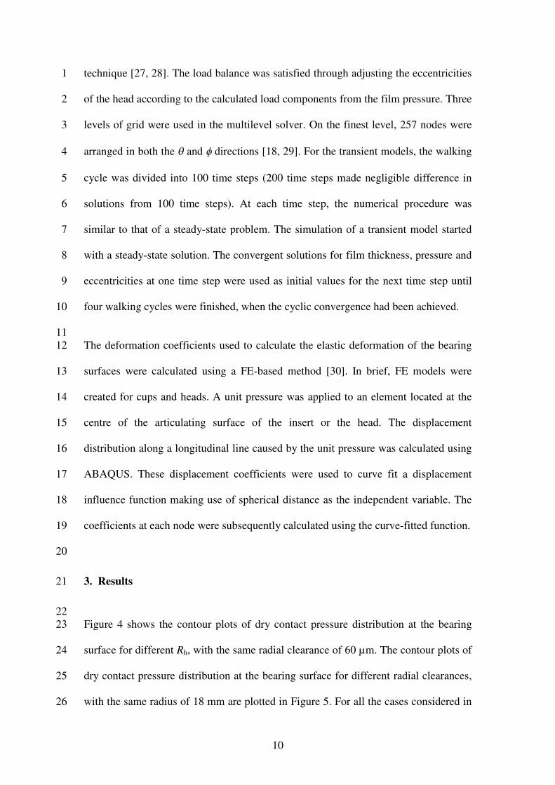
3. Results21
22
Figure 4 shows the contour plots of dry contact pressure distribution at the bearing23
surface for different Rh, with the same radial clearance of 60 µm. The contour plots of24
dry contact pressure distribution at the bearing surface for different radial clearances,25
with the same radius of 18 mm are plotted in Figure 5. For all the cases considered in26

11
the present study for the dry contact mechanics of CoM bearings, the maximum1
contact pressures and contact areas predicted from the FE method and the Hertz2
contact theory are listed in Table 2. The contour plots of film pressure predicted by3
steady-state EHL for different radii with the same radial clearance are shown in4
Figure 6. Figure 7 shows the contour plots of film pressure predicted by steady-state5
EHL for different radial clearances with a fixed Rh of 18 mm. In Figure 8, the6
minimum film thickness predicted from the present steady-state EHL model of a CoM7
THR (Rh = 18 mm, c = 60 µm) is compared with that calculated from the H-D formula8
[31, 32], which is as follows9
21.0
2
65.0
min 80.2
RE
w
RE
u
R
h (9)10
where u is the effective entraining velocity, calculated from u = のRh/2 for the present11
problem. Figure 9 shows the effects of radius and radial clearance on the steady-state12
film thickness along the central line in the entraining direction. Figure 10 compares13
the central and minimum film thicknesses and the maximum pressure between CoM14
THRs with different radii but a similar radial clearance, predicted from transient EHL15
models. The central and minimum film thicknesses and the maximum pressure16
predicted from transient EHL models for CoM THRs with different radial clearances17
are compared in Figure 11. Figure 12 compares the central and minimum film18
thicknesses and the maximum pressure of CoC, CoM and MoM THRs, predicted from19
transient EHL models.20
21
4. Discussion22
23
The profiles of the dry contact pressure of CoM THRs investigated in the present24
study showed typical characteristics of hard-on-hard hip bearings. As shown in25

12
Figures 4 and 5, the maximum pressure was at the centre of the contact area; and the1
pressure distribution closely resembled the Hertz contact distribution. Moreover, for2
all the cases solved in the present study, the differences in the maximum contact3
pressures and contact areas predicted by Hertz contact theory and FE methods were4
less than 7 percent (Table 2). These characteristics are similar to spherical MoM [17]5
and CoC [33] total hip bearings with thick cups. It should be noted that the backing6
materials underneath the CoCr insert in the present study and those in the previous7
studies on hard-on-hard hip bearings were different. In the present study, the materials8
underneath the insert were titanium shell and equivalent bone. In the MoM study [17],9
the backing materials were cement and bone, while in the CoC study [33], the10
material underneath the ceramic inlay was an ultra-high molecular weight11
polyethylene inlay. However, similar profiles were obtained for the contact pressure12
of these three types of THRs. Therefore, it can be expected that for all hard-on-hard13
hip bearings, if the insert (cup) is thick enough, the backing material underneath the14
inset (cup) and the curvature associated with the ball-in-socket contact have a small15
effect on the contact mechanics at the bearing surfaces.16
17
Since film pressure is almost identical to the dry contact pressure over most of the18
EHL conjunction, especially under a heavy load such as that considered in the steady-19
state EHL models of the present study, the similarity between the film pressure and20
the dry contact pressure is consistent with EHL theory and thus provides some support21
for the solutions of both the dry contact mechanics and steady-state EHL models. It is22
clear that the profiles and the magnitudes of the film pressures shown in Figures 6 and23
7 closely resembled those of the corresponding dry contact pressures shown in24
Figures 4 and 5. For example, the maximum dry contact pressure for the CoM THR25

13
with the radius of 14 mm and clearance of 60 µm was 112.6 MPa, while the1
corresponding maximum film pressure was 112.06 MPa.2
3
For most of the steady-state cases investigated in Figure 8, the minimum film4
thicknesses predicted from the present numerical solution agreed well with the H-D5
formula, since such a thick-cup CoM hip bearing can be approximated as a ‘semi-6
infinite solid’ model. However, under heavy load and smaller viscosity, differences in7
the minimum film thicknesses between the present numerical solution and the H-D8
formula became obvious. Most likely, this is because when the lubricant film is9
extremely thin, more mesh nodes are needed to capture the minimum film thickness10
of the steady-state EHL. It is also possible that the Hamrock-Dowson formula intends11
to produce slightly thicker minimum film thickness, as indicated in a previous study12
for MoM hip implants [34]. A further investigation has to involve finer meshes.13
However, currently, the accurate calculation of the deformation coefficients of the14
bearing surfaces of hip implants for a large number of nodes is still challenging due to15
the requirement of extremely large computational cost for FE models.16
17
The FE solutions of dry contact mechanics (Figures 4 and 5) and full numerical18
analyses of steady-state (Figures 6, 7, and 9) and transient EHL (Figures 10 and 11)19
indicated that head radius and radial clearance are important parameters for the20
tribological performance of CoM THRs in terms of reducing dry and lubricated21
contact pressure. For given bearing materials, dry contact and film pressures are22
generally determined by load and contact area. For the same load, the larger the23
contact area, the lower the dry contact and film pressures. Increasing size of hip24
replacements or/and reducing clearance between the insert and head can increase the25
contact area between the surfaces. As shown in Figures 4 and 6 and listed in Table 2,26

14
for a fixed radial clearance of 60 µm and a load of 3000 N, increasing Rh from 14 to1
18 mm resulted in a 50 percent increase in contact area. As a result, the maximum dry2
contact and film pressures decreased from 112.60 to 78.41 MPa and 112.06 to 78.523
MPa, respectively. For a fixed Rh of 18 mm and a load of 3000 N, reducing c from4
100 to 30 µm resulted in an increase in the contact area from 95.23 to 42.23 mm2.5
Correspondingly, the maximum dry contact and film pressures decreased from 110.506
to 49.34 MPa and 111.49 to 48.98 MPa (Figures 5 and 7, Table 2), respectively.7
Moreover, the effects of radius and radial clearance on the film pressure are also8
clearly shown in transient EHL analyses (Figures 10 c and 11 c).9
10
EHL analyses indicated that head radius and radial clearance are important parameters11
to enhance lubricant film thickness of CoM THRs. With a given angular velocity, a12
larger head radius improves the effective entraining velocity, entraining more13
lubricant into the contact conjunction, and slightly increases the contact area, all with14
the overall effect of increasing the lubricant film thickness. Therefore, an increase in15
the central and minimum film thicknesses is observed in Figures 9 a and 10 for CoM16
THRs if the radius increased from 14 to 18 mm. For example, the average increases in17
the central and minimum film thicknesses in one walking cycle obtained from18
transient EHL analyses were 45 percent and 80 percent. It should be noted that19
although it has been recognized that the radius of head is one of the key parameters of20
enhancing lubrication and minimizing wear of hard-on-hard total hip bearings, to the21
authors’ knowledge, no full numerical analyses of the effect of radius on the22
lubrication performance of hard-on-hard total hip bearings have been published.23
Therefore, the full numerical solutions presented in Figures 9 a and 10 are also able to24
provide theoretical supports for other types of hard-on-hard hip bearing.25
26

15
A smaller clearance produces a more conforming geometry. Such a conforming1
geometry reduces the pressure gradient at the inlet, resulting in the reduction in the2
Poiseuille flow and an increase in the Couette flow. As a result, more lubricant is3
allowed to flow into the loaded area to improve lubrication [35]. Therefore, a decrease4
in radial clearance from 100 to 30 µm caused the increase of film thickness (Figures 95
b and 11). The average increases in central and minimum film thicknesses in one6
walking cycle obtained from transient EHL analyses were twofold and threefold,7
respectively (Figure 11). This conclusion of the effect of the radial clearance on the8
lubrication performance of CoM hip bearings obtained from the present full numerical9
analyses was consistent with a previous study for general hard-on-head bearings based10
on the H-D formula [32].11
12
The predictions of the effects of radius and radial clearance on the lubrication13
performance of CoM THRs made in the present study can be validated by published14
wear test results. Wear and lubrication are closely linked from a tribological point of15
view. An effective lubricant film is able to reduce wear significantly, while severe16
wear may occur if the lubricant film is not thick enough to separate the bearing17
surfaces. It has been shown that with similar or larger average radial clearances, 36-18
mm-diameter CoM bearings generated significantly lower volumetric loss than 32-19
mm-diameter CoM bearings [11, 12]. It has also been reported that the wear rate of20
38-mm-diameter CoM bearings demonstrated lower wear rate than 32-mm-diameter21
CoM bearings, even though radial clearance of 38-mm-diameter CoM bearings was22
larger [13]. These results were all consistent with the effect of head radius on the23
lubrication performance of CoM THRs predicted in the present study. A smaller radial24
clearance producing increased film thickness agreed well with a simulator wear test of25

16
CoM bearings [36], in which small clearances showed low wear than larger clearances1
for 28-mm-diameter CoM bearings.2
3
The film thickness of CoM THR was thicker than that of the CoC THR, but thinner4
than that of the MoM (Figure 12), as expected. Under the same walking conditions,5
the only factor causing differences in the film thicknesses of the three types of bearing6
was the material properties of the components, which generated different elastic7
deformation under the same load. Since the elastic modulus of alumina is larger than8
that of CoCr alloy, the deformation for hip bearings with ceramic components was9
smaller, producing a thinner lubricant film. However, it is interesting to estimate the10
mode of lubrication of the three types of hip prosthesis. The estimation is usually11
based on the lambda ratio, which can be defined as:12
2
a(cup)
2
a(head)
min
RR
h
(10)13
where hmin is the minimum film thickness during a walking cycle; Ra(head) and Ra(cup)14
are average roughnesses of the head and cup/insert respectively. In the present study, 415
nm for ceramic surface roughness and 10 nm for CoCr surface roughness were16
adopted [7], resulting in composite roughnesses of 5.66, 10.78 and 14.14 nm for CoC,17
CoM and MoM bearings, respectively. As shown in Figure 12, with similar structure18
and geometry, the CoC THR may operate in fluid film lubrication during the whole19
walking gait; the CoM THR benefited fluid film lubrication during 80 percent of a20
walking cycle; but the MoM THR only operated in fluid film lubrication during 3021
percent of a walking cycle. Such an improvement of lubrication mode in CoM hip22
bearing may contribute to the reduction of metallic wear and friction of CoM hip23
bearings, compared with MoM hip bearings [5-9].24
25

17
There are a few limitations in the present study. For example, the roughness of the1
bearing surfaces, which plays an important role in the lubrication and wear of hip2
bearings, was not considered in the EHL solution. Moreover, only steady-state and3
normal walking conditions were considered in the present study. However, under4
adverse conditions such as start-up and stopping of walking, the lubrication5
performance and wear of hip bearings could be significantly different from normal6
walking. It should also be pointed out that the mechanism for the reduced wear of the7
CoM hip bearings is complicated. Besides the improvement of lubrication, other8
factors of CoM hip bearings, such as the improvement of hardness, differential9
hardness reducing adhesive wear [8], and reduction in corrosive wear [37] may also10
contribute to the lower wear of this novel hip bearing. Furthermore, an enhancement11
of fluid lubrication may also help in establishment of an effective nano boundary layer12
on the surface of the metal [38].13
14
5. Conclusion15
16
For the first time, the dry contact mechanics, steady-state and transient EHL of CoM17
hip bearings were solved using full numerical methods. Typical dry contact and film18
pressure distributions and film profiles were predicted for CoM THRs. The effects of19
the geometric parameters, R2 and c, on lubricated and unlubricated pressure20
distributions and steady-state and transient fluid film thicknesses were analyzed. The21
lubrication performance of CoM hip bearing was compared with that of CoC and22
MoM hip bearings. The following conclusions can be drawn from this study:23
(1) The profiles of the dry and lubricated contact pressures of CoM THRs24
showed typical characteristics of hard-on-hard hip bearings: the maximum25

18
pressure was at the centre of the contact area; the pressure distribution1
closely resembled the Hertz contact distribution.2
(2) Full numerical analyses of contact mechanics and EHL models indicated3
that head radius and radial clearance are important parameters in the contact4
mechanics and EHL of CoM THRs. Increasing head radius and reducing5
radial clearance reduced contact pressure and enhanced lubricant film.6
(3) The effects of head radius and radial clearance on lubrication performance7
were consistent with wear tests of CoM hip bearings reported in the8
literature.9
(4) The film thickness of CoM hip bearing was thicker than that of the CoC hip10
bearing, but thinner than that of the MoM hip bearing. However, CoC and11
CoM hip bearings are more likely to benefit full fluid film lubrication than12
MoM hip bearings.13
14
6. Acknowledgement15
16
This work was supported by EPSRC and partly supported by the NIHR (National17
Institute for Health Research) as part of collaboration with the LMBRU (Leeds18
Musculoskeletal Biomedical Research Unit). JF is an NIHR Senior Fellow.19
20
21
Conflict of interest statement22
23
JF is a consultant to DePuy, the manufacturer of CoM MoM and CoC bearings. The24
University of Leeds and JF receive royalty income from DePuy arising from the25
transfer of intellectual property on bearing technology.26

19
1
2
3
4
5
6
7
8
9
10
11
12
13
14
15
16
17
18
19
20
21

20
References:
1. Brown C, Fisher J, Ingham E. Biological effects of clinically relevant wear
particles from metal-on-metal hip prostheses. Proceedings of the Institution of
Mechanical Engineers, Part H: Journal of Engineering in Medicine 2006;
220(H2): 355-369.
2. Crawford R, Ranawat CS, Rothman RH. Metal on Metal: Is It Worth the Risk?
Journal of Arthroplasty 2010; 25(1): 1-2.
3. Haddad FS, Thakrar RR, Hart AJ, Skinner JA, Nargol AVF, Nolan JF, et al.
Metal-on-metal bearings THE EVIDENCE SO FAR. Journal of Bone and
Joint Surgery-British Volume 2011; 93B(5): 572-579.
4. Langton DJ, Joyce TJ, Jameson SS, Lord J, Van Orsouw M, Holland JP, et al.
Adverse reaction to metal debris following hip resurfacing - The influence of
component type, orientation and volumetric wear. Journal of Bone and Joint
Surgery-British Volume 2011; 93B(2): 164-171.
5. Firkins PJ, Tipper JL, Ingham E, Stone MH, Farrar R, Fisher J. A novel low
wearing differential hardness, ceramic-on-metal hip joint prosthesis. Journal of
Biomechanics 2001; 34(10): 1291-1298.
6. Williams S, Schepers A, Isaac G, Hardaker C, Ingham E, van der Jagt D, et al.
The 2007 Otto Aufranc Award. Ceramic-on-metal hip arthroplasties: a
comparative in vitro and in vivo study. Clinical Orthopaedics and Related
Research 2007; 465: 23-32.
7. Brockett C, Williams S, Jin ZM, Isaac G, Fisher J. Friction of total hip
replacements with different bearings and loading conditions. Journal of
Biomedical Materials Research Part B-Applied Biomaterials 2007; 81B(2):
508-515.
8. Barnes CL, DeBoer D, Corpe RS, Nambu S, Carroll M, Timmerman I. Wear
performance of large-diameter differential-hardness hip bearings. Journal of
Arthroplasty 2008; 23(6): 56-60.
9. Bishop NE, Waldow F, Morlock MM. Friction moments of large metal-on-
metal hip joint bearings and other modern designs. Medical Engineering &
Physics 2008; 30(8): 1057-1064.
10. Isaac GH, Brockett C, Breckon A, van der Jagt D, Williams S, Hardaker C, et
al. Ceramic-on-metal bearings in total hip replacement - Whole blood metal
ion levels and analysis of retrieved components. Journal of Bone and Joint
Surgery-British Volume 2009; 91B(9): 1134-1141.
11. Affatato S, Spinelli M, Squarzoni S, Traina F, Toni A. Mixing and matching in
ceramic-on-metal hip arthroplasty: An in-vitro hip simulator study. Journal of

21
Biomechanics 2009; 42(15): 2439-2446.
12. Affatato S, Spinelli M, Zavalloni M, Traina F, Carmignato S, Toni A. Ceramic-
On-Metal for Total Hip Replacement: Mixing and Matching Can Lead to High
Wear. Artificial Organs 2010; 34(4): 319-323.
13. Ishida T, Clarke IC, Donaldson TK, Shirasu H, Shishido T, Yamamoto K.
Comparing Ceramic-Metal to Metal-Metal Total Hip Replacements-A
Simulator Study of Metal Wear and Ion Release in 32-and 38-mm Bearings.
Journal of Biomedical Materials Research Part B-Applied Biomaterials 2009;
91B(2): 887-896.
14. FDA approves first ceramic-on-metal total hip replacement system. [updated
06/14/2011 cited 10/16/2011]; Available from:
http://www.fda.gov/NewsEvents/Newsroom/PressAnnouncements/ucm259061
.htm.
15. Dowson D. New joints for the Millennium: wear control in total replacement
hip joints. Proceedings of the Institution of Mechanical Engineers Part H-
Journal of Engineering in Medicine 2001; 215(H4): 335-358.
16. Williams SR, Wu JJ, Unsworth A, Khan I. Tribological and surface analysis of
38 mm alumina-as-cast Co-Cr-Mo total hip arthroplasties. Proceedings of the
Institution of Mechanical Engineers Part H-Journal of Engineering in
Medicine 2009; 223(H8): 941-954.
17. Jagatia M, Jin ZM. Elastohydrodynamic lubrication analysis of metal-on-metal
hip prostheses under steady state entraining motion. Proceedings of the
Institution of Mechanical Engineers Part H-Journal of Engineering in
Medicine 2001; 215(H6): 531-541.
18. Wang FC, Jin ZM. Transient elastohydrodynamic lubrication of hip joint
implants. Journal of Tribology-Transactions of the ASME 2008; 130(1):
011007.
19. Bergmann G, Deuretzbacher G, Heller M, Graichen F, Rohlmann A, Strauss J,
et al. Hip contact forces and gait patterns from routine activities. Journal of
Biomechanics 2001; 34(7): 859-871.
20. Jin ZM. Theoretical studies of elastohydrodynamic lubrication of artificial hip
joints. Proceedings of the Institution of Mechanical Engineers, Part J: Journal
of Engineering Tribology 2006; 220(J8): 719-727.
21. ISO 14242-1, Implants for Surgery - Wear of Total Hip-Joint Prostheses - Part
1: Loading and Displacement Parameters for Wear-Testing Machines and
Corresponding Environmental Conditions for Test. 2002.
22. Cooke AF, Dowson D, Wright V. The rheology of synovial fluid and some
potential synthetic lubricants for degenerate synovial joints. Engineering in
Medicine 1978; 7: 66-72.

22
23. Yao JQ, Laurent MP, Johnson TS, Blanchard CR, Crowninshield RD. The
influences of lubricant and material on polymer/CoCr sliding friction. Wear
2003; 255(1-6): 780-784.
24. Wang WZ, Jin ZM, Dowson D, Hu YZ. A study of the effect of model
geometry and lubricant rheology upon the elastohydrodynamic lubrication
performance of metal-on-metal hip joints. Proceedings of the Institution of
Mechanical Engineers Part J-Journal of Engineering Tribology 2008; 222(J3):
493-501.
25. Meng QE, Gao LM, Liu F, Yang PR, Fisher J, Jin ZM. Transient
elastohydrodynamic lubrication analysis of a novel metal-on-metal hip
prosthesis with an aspherical acetabular bearing surface. Journal of Medical
Biomechanics 2009; 24(5): 352-362.
26. Gao L, Wang F, Yang P, Jin Z. Effect of 3D physiological loading and motion
on elastohydrodynamic lubrication of metal-on-metal total hip replacements.
Medical Engineering & Physics 2009; 31(6): 720-729.
27. Gao LM, Meng QE, Wang FC, Yang PR, Jin ZM. Comparison of numerical
methods for elastohydrodynamic lubrication analysis of metal-on-metal hip
implants: multi-grid verses Newton-Raphson. Proceedings of the Institution of
Mechanical Engineers, Part J: Journal of Engineering Tribology 2007; 221(J2):
133-140.
28. Venner CH, Multigrid solution of the EHL line and point contact problems.
PhD Thesis. 1991, Enschede: University of Twente.
29. Liu F, Jin ZM, Hirt F, Rieker C, Roberts P, Grigoris P. Transient
elastohydrodynamic lubrication analysis of metal-on-metal hip implant under
simulated walking conditions. Journal of Biomechanics 2006 a; 39(5): 905-
914.
30. Wang FC, Jin ZM. Prediction of elastic deformation of acetabular cups and
femoral heads for lubrication analysis of artificial hip joints. Proceedings of
the Institution of Mechanical Engineers Part J-Journal of Engineering
Tribology 2004 a; 218(J3): 201-209.
31. Hamrock BJ, Dowson D. Elastohydrodynamic lubrication of elliptical contacts
for materials of low elastic-modulus. I: Fully flooded conjunction. Journal of
Lubrication Technology-Transactions of the ASME 1978; 100(2): 236-245.
32. Jin ZM, Dowson D, Fisher J. Analysis of fluid film lubrication in artificial hip
joint replacements with surfaces of high elastic modulus. Proceedings of the
Institution of Mechanical Engineers Part H-Journal of Engineering in
Medicine 1997; 211(3): 247-256.
33. Mak MM, Jin ZM. Analysis of contact mechanics in ceramic-on-ceramic hip
joint replacements. Proceedings of the Institution of Mechanical Engineers

23
Part H-Journal of Engineering in Medicine 2002; 216(H4): 231-236.
34. Jalali-Vahid D, Jin ZM, Dowson D. Isoviscous elastohydrodynamic lubrication
of circular point contacts with particular reference to metal-on-metal hip
implants. Proceedings of the Institution of Mechanical Engineers Part J-
Journal of Engineering Tribology 2003; 217(J5): 397-402.
35. Meng QE, Liu F, Fisher J, Jin ZM. Transient elastohydrodynamic lubrication
analysis of a novel metal-on-metal hip prosthesis with a non-spherical femoral
bearing surface. Proceedings of the Institution of Mechanical Engineers Part
H-Journal of Engineering in Medicine 2011; 225(H1): 25-37.
36. Haider H, Weisenburger JN, Naylor MG, Schroeder DW, Croson RE, Garvin
KL. Bearing diameter, radial clearance and their effect on wear in ceramic-on-
metal total hip replacements. In 54th Annual Meeting of the Orthopaedic
Research Society. 2008. San Francisco, California, USA. Poster 1792.
37. Figueiredo-Pina CG, Yan Y, Neville A, Fisher J. Understanding the differences
between the wear of metal-on-metal and ceramic-on-metal total hip
replacements. Proceedings of the Institution of Mechanical Engineers Part H-
Journal of Engineering in Medicine 2008; 222(H3): 285-296.
38. Pourzal R, Theissmann R, Williams S, Gleising B, Fisher J, Fischer A.
Subsurface changes of a MoM hip implant below different contact zones.
Journal of the Mechanical Behavior of Biomedical Materials 2009; 2(2): 186-
191.

24
Nomenclature:
c radial clearance between head and insert
ex, ey eccentricity components of the femoral head in x and y directions
Ec, Eh elastic moduli of insert and head, respectively
E equivalent elastic modulus of bearing surfaces
fx, fy, fz calculated load components
h film thickness
hmin the minimum film thickness
p pressure
r contact radius calculated from Hertz contact theory
R radius of the equivalent ball of the equivalent ball-on-plane model
Ra(cup) average roughness of the insert
Ra(head) average roughness of the head
Rh radius of femoral head
Rc radius of the cup/insert
t time (s)
u effective entraining velocity
wy applied load in y direction
x, y, z Cartesian coordinates
elastic deformation the femoral head and acetabular cup
viscosity of synovial fluid
, angular coordinates in the entraining and side-leakage directions
respectively.
lambda ratio
c, h Poison’s rations of insert and head, respectively
angular velocity

25
Captions
Table 1 Material properties used for CoCr alloy, titanium, alumina and equivalent
support layer
Table 2 Comparison of the predicted maximum contact pressure and contact area
between the present finite element study and the Hertz contact theory
Figure 1 A ball-in-socket configuration for contact mechanics and EHL analyses
of CoM bearings
Figure 2 Variation in the load (a) and velocity (b) of the walking conditions based
on ISO 14242-1
Figure 3 Definition of spherical coordinates and mesh grid
Figure 4 Contour plots of dry contact pressure (MPa) at the bearing surface of
CoM hip replacements with a similar radial clearance (60 µm) but
different radii: (a) 14 mm, (b) 16 mm, (c) 18 mm
Figure 5 Contour plots of dry contact pressure (MPa) at the bearing surface of
CoM hip replacements with a similar radius (18 mm) but different radial
clearances: (a) 100 µm, (b) 30 µm
Figure 6 Contour plots of steady-state film pressure (MPa) in CoM hip
replacements with similar radial clearance (60 µm) but different radii: (a)
14 mm, (b) 16 mm, (c) 18 mm
Figure 7 Contour plots of steady-state film pressure (MPa) in CoM hip
replacements with similar radius (18 mm) but different radial clearances:
(a) 100 µm, (b) 30 µm
Figure 8 Minimum film thicknesses produced by the H-D formula and current
numerical model for a 36-mm-diameter CoM THR with radial clearance
of 60 µm under different loads
Figure 9 Comparison of steady-state film thickness on the central line along the
entraining direction for different radii (c = 60 µm) (a) and radial
clearances (Rh = 18 mm) (b)
Figure 10 Prediction of the central film thickness (a), minimum film thickness (b)
and maximum pressure (c) by transient EHL solution for CoM hip
replacements with a similar radial clearance (60 µm) but different radii,
under transient conditions based on ISO 14242-1

26
Figure 11 Prediction of the central film thickness (a), minimum film thickness (b)
and maximum pressure (c) by transient EHL solution for CoM hip
replacements with a similar size (18 mm) but different radial clearances,
under transient conditions based on ISO 14242-1
Figure 12 Under transient conditions based on ISO 14242-1, prediction of the
central film thickness (a), minimum film thickness (b) and maximum
pressure (c) by transient EHL solution for CoM, CoC and MoM hip
replacements with similar size (18 mm) and radial clearance (60 µm)

27
Table 1 Material properties used for CoCr alloy, titanium, alumina and equivalent
support layer
Elastic modulus (GPa) Poisson’s ratio
CoCr 210 0.3
Titanium 110 0.3
Equivalent support layer 2.27 0.23
Alumina 380 0.26
Table 2 Comparison of the predicted maximum contact pressure and contact area
between the present finite element study and the Hertz contact theory
Radius
(mm)
Radial
clearance
(µm)
Maximum contact pressure
(MPa) Contact area (mm2)
Finite element Hertz Finite element Hertz
14 60 112.60 105.40 40.51 42.69
16 60 92.89 88.24 48.52 50.99
18 60 78.41 75.44 61.35 59.65
18 30 49.34 47.58 95.29 94.58
18 100 110.50 105.89 42.23 42.50

28
Figure 1 A ball-in-socket configuration for contact mechanics and EHL analyses of
CoM bearings

29
(a)
(b)
Figure 2 Variation in the load (a) and velocity (b) of the walking conditions based on
ISO 14242-1

30
Figure 3 Definition of spherical coordinates and spherical mesh grid

31
(a)
(b)
(c)
Figure 4 Contour plots of dry contact pressure (MPa) at the bearing surface of CoM
hip replacements with a similar radial clearance (60 µm) but different radii: (a) 14
mm, (b) 16 mm, (c) 18 mm

32
(a) (b)
Figure 5 Contour plots of dry contact pressure (MPa) at the bearing surface of CoM
hip replacements with a similar radius (18 mm) but different radial clearances: (a) 100
µm, (b) 30 µm

33
(a)
(b) (c)
Figure 6 Contour plots of steady-state film pressure (MPa) in CoM hip replacements
with similar radial clearance (60 µm) but different radii: (a) 14 mm, (b) 16 mm, (c) 18
mm

34
(a) (b)
Figure 7 Contour plots of steady-state film pressure (MPa) in CoM hip replacements
with similar radius (18 mm) but different radial clearances: (a) 100 µm, (b) 30 µm

35
Figure 8 Minimum film thicknesses produced by the H-D formula and current
numerical model under different loads for a 36-mm-diameter CoM THR with radial
clearance of 60 µm

36
(a)
(b)
Figure 9 Comparison of steady-state film thickness on the central line along the
entraining direction for different radii (c = 60 µm) (a) and radial clearances (Rh = 18
mm) (b)

37
(a)
(b)
(c)
Figure 10 Prediction of the central film thickness (a), minimum film thickness (b) and
maximum pressure (c) by transient EHL solution for CoM hip replacements with a
similar radial clearance (60 µm) but different radii, under transient conditions based
on ISO 14242-1

38
(a)
(b)
(c)
Figure 11 Prediction of the central film thickness (a), minimum film thickness (b) and
maximum pressure (c) by transient EHL solution for CoM hip replacements with a
similar size (18 mm) but different radial clearances, under transient conditions based
on ISO 14242-1

39
(a)
(b)
(c)
Figure 12 Under transient conditions based on ISO 14242-1, prediction of the central
film thickness (a), minimum film thickness (b) and maximum pressure (c) by transient
EHL solution for CoM, CoC and MoM hip replacements with similar size (18 mm)
and radial clearance (60 µm)