Contact and reservation: CEFcefnpc.free.fr/IMG/pdf/Plaquette_commerciale-GB.pdf · • any...
6
RAILWAY TESTING CENTRE IN VALENCIENNES A MAJOR ASSET FOR EVERY RAILWAY PROJECT LEADER The purpose of the Centre is to contribute to the preparation and to the development of the certifi- cation process of railway rolling stock and their associated railway systems. To this effect, the Rail Testing Centre in Valenciennes offers railway project leaders an outstanding experimental plat- form in order to help them test technological breakthroughs, to enhance the performances of the equipment and to implement systems with proven reliability and flawless safety. CEF CEF A high-tech tool REGION NORD PAS DE CALAIS
Transcript of Contact and reservation: CEFcefnpc.free.fr/IMG/pdf/Plaquette_commerciale-GB.pdf · • any...

RAILWAY TESTING CENTREIN VALENCIENNES
A MAJOR ASSET FOR EVERYRAILWAY PROJECT LEADER
The purpose of the Centre is to contribute to thepreparation and to the development of the certifi-cation process of railway rolling stock and theirassociated railway systems. To this effect, the RailTesting Centre in Valenciennes offers railway project leaders an outstanding experimental plat-form in order to help them test technologicalbreakthroughs, to enhance the performances ofthe equipment and to implement systems withproven reliability and flawless safety.
CEFCEF
CEFCEF
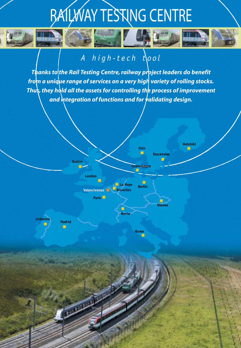
RAILWAY TESTING CENTRE
A h i g h - t e c h t o o l
Stationary Train Initialisation Beacon
Docking Detector
Precise Stop announcement Beacon
Moving Train Initialisation Beacon
Reloc. Beacon
Motorized Point
signal 2 aspects
signal 1 aspect
IAGO base station
terminaison guide
Emergency Stop Plunger
TEST TRACK FOR AUTOMATIC PILOTING PASC
Functionalities available• Centralised control.
• Operation signalling.
• Driving automatic controls.
• Train-ground /ground-train transmission.
• Management of distance between 2 trains.
• Accurate stops in station.
• Passenger exchange.
• Voice and data communication.
• Simulation of operation in standard and
downgraded modes.
Components• Route command and control.
• Route locking information system (2 ASCV).
• Track circuits, light indicators, point motors.
• Automatic piloting system (2 SACEM areas) and position
beacons (spot transmission).
• Wave guide bi-directional transmission (IAGO), (evolu-
tionary transmission support)
• Transmission through radiating cable.
• Front door.
Centre d'Essais Ferroviaire in Region Nord-Pas-de-CalaisRue Fresnel – 59494 PETITE-FORET – France Tel. : +33/327 323 025 – Fax : +33/327 324 650
Contact and reservation:Jean-Marie VANZEMBERG
+33/ 607 837 146E.mail : [email protected]
•Li
lle –
Impr
imé
en F
ranc
e –
Mar
s 200
3
Valenciennes
Paris
Vienne
Stockholm
Dublin
HelsinkiOslo
Berne
Rome
BruxellesLa Haye
Copenhague
Berlin
London
MadridLisbonne
R E G I O N N O R D P A S D E C A L A I S
A h i g h - t e c h t o o l
h
m q
s o
in
o
e
v
h
Thanks to the Rail Testing Centre, railway project leaders do benefit
from a unique range of services on a very high variety of rolling stocks.
Thus, they hold all the assets for controlling the process of improvement
and integration of functions and for validating design.
FlashTriptyque CE-GB 1/12/03 18:41 Page 1 (1,1)
A unique range of services An infrastructure dedicated to the engineering and validation of:• the rolling stock ;• the signalling components and/or architecture;• the system architecture of automatic or semi-automatic pilot within a controlled electrical and mechanical referential system.
A Solution for testing the stress-strainbehaviour of:• any mechanical components from the track or from the signalling system;• any types of railway vehicles, special or not.
The reception of operating/maintenancestaffs from companies networks • so that they get used with and trained in the new products integrated intothe rail architecture.
The guaranteed adaptability of the infrastructure • feasibility study of the specific testing platform or test bench to be implemented according to the target defined.
A great variety of rolling stocks• Gauge : UIC up to 22.5 tons per axle ;• diesel, electric or bi-mode ;• single composition or multiple unit.
- Locomotive up to 5000 KvA.- Single- or double-deck railcar.- Self-propelled locomotive.- Metro.- Tramway.- Tram-train.- Rail-born car for inspection, works, measures
with on-board data-acquisition system.- Freight car.- Demonstrator.- Track motor car.
Whatever test is carried out, for prototypes or series, each type of test will deter-mine which of the three Testing Centre’s circuits the equipment will be assignedto.These circuits are connected to a management unit which controls andrecords the experiments.
TESTS RUN ON ROLLING STOCKType d’essaiDébattement/caisses
Suspension
Bilan auxiliaires
Bilan pneumatique
Consommation énergie
Mesures bruit intérieur
Mesures bruit extérieur
Niveau sonore avertisseurs
Essais de freins
Distances d’arrêt
Performances au démarrage
Sauts/chutes de tension
Essais anti-patinage
Captation énergie
Freinage élect.rhéostatique
Freinage élect. récupération
Passage sections de commut.
Freinage sur ligne en CC
Essais anti-enrayage
Captation de signalisation
Essais de comportement en endurance
Enregistrements paramètres
Fonctionnement graisseurs
Conduite automatique
Compatibilité électromagnétique
Freinage conjugué
Courants harmoniques
Captation de courant / décollement de panto
Inscription en courbe / dévers maxi
Accostage basse vitesse
Essais de couplabilité entre rames
Mesure de rejets d’émission de poussières
Sollicitations mécaniques bogie
Contact roue-rail
Infrastructure et moyens CEFessai possible
essai possible
Hall technique à poste fixe
Hall technique à poste fixe
Comptage énergie/station
VEV/VAE
Tronçon aménagé/VEV
VEV
VEV
Section droite VEV
VEV
VEV, outils de tests s/station
VEV, VAE
VEV, VAE
VEV,VAE
VEV,VAE
VEV
VEV
VEV
PASC
VAE
VEV,VAE
VEV,VAE
PASC
VEV
VEV
VEV,VAE
VEV,VAE
VEV
VEV
VEV,VAE
VEV,VAE
VEV,VAE
VEV, VAE
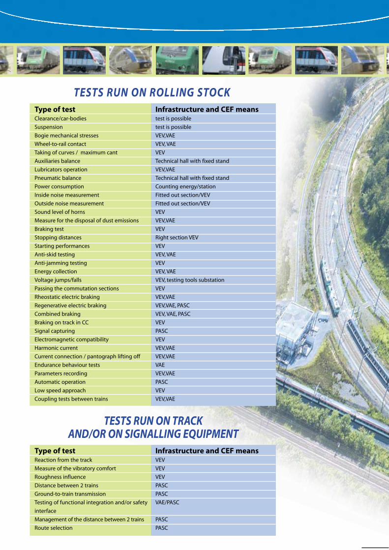
Type of test Clearance/car-bodies
Suspension
Bogie mechanical stresses
Wheel-to-rail contact
Taking of curves / maximum cant
Auxiliaries balance
Lubricators operation
Pneumatic balance
Power consumption
Inside noise measurement
Outside noise measurement
Sound level of horns
Measure for the disposal of dust emissions
Braking test
Stopping distances
Starting performances
Anti-skid testing
Anti-jamming testing
Energy collection
Voltage jumps/falls
Passing the commutation sections
Rheostatic electric braking
Regenerative electric braking
Combined braking
Braking on track in CC
Signal capturing
Electromagnetic compatibility
Harmonic current
Current connection / pantograph lifting off
Endurance behaviour tests
Parameters recording
Automatic operation
Low speed approach
Coupling tests between trains
Infrastructure and CEF meanstest is possible
test is possible
VEV,VAE
VEV, VAE
VEV
Technical hall with fixed stand
VEV,VAE
Technical hall with fixed stand
Counting energy/station
Fitted out section/VEV
Fitted out section/VEV
VEV
VEV,VAE
VEV
Right section VEV
VEV
VEV, VAE
VEV
VEV, VAE
VEV, testing tools substation
VEV
VEV,VAE
VEV,VAE, PASC
VEV, VAE, PASC
VEV
PASC
VEV
VEV,VAE
VEV,VAE
VAE
VEV,VAE
PASC
VEV
VEV,VAE
Type of test Reaction from the track
Measure of the vibratory comfort
Roughness influence
Distance between 2 trains
Ground-to-train transmission
Testing of functional integration and/or safety
interface
Management of the distance between 2 trains
Route selection
Infrastructure and CEF means VEV
VEV
VEV
PASC
PASC
VAE/PASC
PASC
PASC
TESTS RUN ON TRACK AND/OR ON SIGNALLING EQUIPMENT
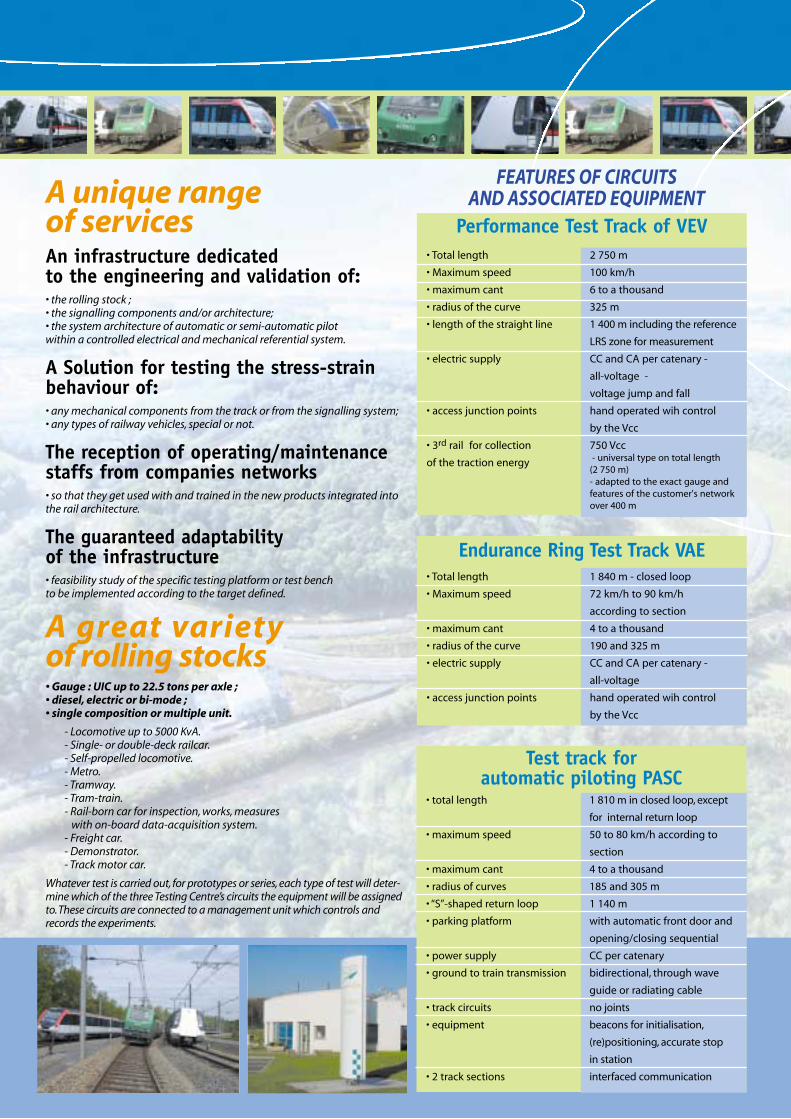
• Total length
• Maximum speed
• maximum cant
• radius of the curve
• length of the straight line
• electric supply
• access junction points
• 3rd rail for collection
of the traction energy
2 750 m
100 km/h
6 to a thousand
325 m
1 400 m including the reference
LRS zone for measurement
CC and CA per catenary -
all-voltage -
voltage jump and fall
hand operated wih control
by the Vcc
750 Vcc - universal type on total length
(2 750 m)- adapted to the exact gauge andfeatures of the customer's networkover 400 m
Performance Test Track of VEV
• Total length
• Maximum speed
• maximum cant
• radius of the curve
• electric supply
• access junction points
1 840 m - closed loop
72 km/h to 90 km/h
according to section
4 to a thousand
190 and 325 m
CC and CA per catenary -
all-voltage
hand operated wih control
by the Vcc
Endurance Ring Test Track VAE
• total length
• maximum speed
• maximum cant
• radius of curves
• “S”-shaped return loop
• parking platform
• power supply
• ground to train transmission
• track circuits
• equipment
• 2 track sections
1 810 m in closed loop, except
for internal return loop
50 to 80 km/h according to
section
4 to a thousand
185 and 305 m
1 140 m
with automatic front door and
opening/closing sequential
CC per catenary
bidirectional, through wave
guide or radiating cable
no joints
beacons for initialisation,
(re)positioning, accurate stop
in station
interfaced communication
Test track for automatic piloting PASC
ADDITIONAL FACILITIES AND EQUIPMENTBuilding, workshops andoffices • Storage track: 180 m
• Workshop:- area: 1 210 m2- dimensions: 110 m x 11 m- service line with a pit:
110 m- energy: supply from
an all-voltage 30-metre-span catenary for auxiliaries standing test
• Offices: independent and cabled modules for customers
• Control centre:- energy management ;- test recordings ;- management of traffic
and security.
• Management centre of the commandcontrol system of the automatic pilot
Additional Means• Ballast loads: up to 150 tons to simulate loadsinside the vehicle.• Command control voltagegenerator: 7.5 KVA (12 to 110 Vcc).• Filling station :200 litres/min.• Elevating cradle for technical intervention onthe roof of the rolling stock.• Anti-fire water-tank car.
Common features• ballastic tracks according
to standard UIC with referential
to the 3 dimensions
• weight on the axle
• standard distance gauge
• rail
• automatic lubricators of rail
adjustable according
to the travelling frequency
and to the number of axles
• communication switches
between circuits - hand operated* with a key locking device, type VCC* with a switch diamond for tram train type vehicle- engine operated
independent, linked by
un-energised track sections
22,5 T maxi
1 435 mm
50 kg/ml – laid at 1/20e
tracks VEV - VAE
track PASC
Power supply• power
• single-phased voltages
• direct -current voltages
• voltage regulations
• cancelling simulation
of distributing substation
• reversing units
3 independent production
units of 5MVA
25kV-50 Hz and 60Hz •
15kV-16Hz 2/3
750 V, 1500 V, 3000 V
according to UIC ranges
regarding these voltages
equivalent distance up to 7 km
- rheostatic or regenerative braking- contribution to combined braking
FEATURES OF CIRCUITS AND ASSOCIATED EQUIPMENT
FEATURES OF CIRCUITS AND ASSOCIATED EQUIPMENT
Features• Coupling single vehicle : 20 tons withbogie UIC, pull chain 1500 Vcc.• Hand-operated or automatic,bi-directional drive.• Power supply from pantograph.• 2 doors with pneumatically controlled sides.• On-board sensors for ground-to-traincommunication.
Tests that can be run• Tests on the features and on theoperation :- of automatic and semi-automaticpiloting systems,- of ground- or lateral-signalling interface.• Tests on sub-systems or components(traction, braking, etc.).• Tests on comfort and safety.
TESTING VEHICLE A mobile test bench can be fitted and adapted torecord all types of mechanical or electrical tests.
FlashTriptyque CE-GB 1/12/03 18:58 Page 2

A unique range of services An infrastructure dedicated to the engineering and validation of:• the rolling stock ;• the signalling components and/or architecture;• the system architecture of automatic or semi-automatic pilot within a controlled electrical and mechanical referential system.
A Solution for testing the stress-strainbehaviour of:• any mechanical components from the track or from the signalling system;• any types of railway vehicles, special or not.
The reception of operating/maintenancestaffs from companies networks • so that they get used with and trained in the new products integrated intothe rail architecture.
The guaranteed adaptability of the infrastructure • feasibility study of the specific testing platform or test bench to be implemented according to the target defined.
A great variety of rolling stocks• Gauge : UIC up to 22.5 tons per axle ;• diesel, electric or bi-mode ;• single composition or multiple unit.
- Locomotive up to 5000 KvA.- Single- or double-deck railcar.- Self-propelled locomotive.- Metro.- Tramway.- Tram-train.- Rail-born car for inspection, works, measures
with on-board data-acquisition system.- Freight car.- Demonstrator.- Track motor car.
Whatever test is carried out, for prototypes or series, each type of test will deter-mine which of the three Testing Centre’s circuits the equipment will be assignedto.These circuits are connected to a management unit which controls andrecords the experiments.
TESTS RUN ON ROLLING STOCKType d’essaiDébattement/caisses
Suspension
Bilan auxiliaires
Bilan pneumatique
Consommation énergie
Mesures bruit intérieur
Mesures bruit extérieur
Niveau sonore avertisseurs
Essais de freins
Distances d’arrêt
Performances au démarrage
Sauts/chutes de tension
Essais anti-patinage
Captation énergie
Freinage élect.rhéostatique
Freinage élect. récupération
Passage sections de commut.
Freinage sur ligne en CC
Essais anti-enrayage
Captation de signalisation
Essais de comportement en endurance
Enregistrements paramètres
Fonctionnement graisseurs
Conduite automatique
Compatibilité électromagnétique
Freinage conjugué
Courants harmoniques
Captation de courant / décollement de panto
Inscription en courbe / dévers maxi
Accostage basse vitesse
Essais de couplabilité entre rames
Mesure de rejets d’émission de poussières
Sollicitations mécaniques bogie
Contact roue-rail
Infrastructure et moyens CEFessai possible
essai possible
Hall technique à poste fixe
Hall technique à poste fixe
Comptage énergie/station
VEV/VAE
Tronçon aménagé/VEV
VEV
VEV
Section droite VEV
VEV
VEV, outils de tests s/station
VEV, VAE
VEV, VAE
VEV,VAE
VEV,VAE
VEV
VEV
VEV
PASC
VAE
VEV,VAE
VEV,VAE
PASC
VEV
VEV
VEV,VAE
VEV,VAE
VEV
VEV
VEV,VAE
VEV,VAE
VEV,VAE
VEV, VAE
Type of test Clearance/car-bodies
Suspension
Bogie mechanical stresses
Wheel-to-rail contact
Taking of curves / maximum cant
Auxiliaries balance
Lubricators operation
Pneumatic balance
Power consumption
Inside noise measurement
Outside noise measurement
Sound level of horns
Measure for the disposal of dust emissions
Braking test
Stopping distances
Starting performances
Anti-skid testing
Anti-jamming testing
Energy collection
Voltage jumps/falls
Passing the commutation sections
Rheostatic electric braking
Regenerative electric braking
Combined braking
Braking on track in CC
Signal capturing
Electromagnetic compatibility
Harmonic current
Current connection / pantograph lifting off
Endurance behaviour tests
Parameters recording
Automatic operation
Low speed approach
Coupling tests between trains
Infrastructure and CEF meanstest is possible
test is possible
VEV,VAE
VEV, VAE
VEV
Technical hall with fixed stand
VEV,VAE
Technical hall with fixed stand
Counting energy/station
Fitted out section/VEV
Fitted out section/VEV
VEV
VEV,VAE
VEV
Right section VEV
VEV
VEV, VAE
VEV
VEV, VAE
VEV, testing tools substation
VEV
VEV,VAE
VEV,VAE, PASC
VEV, VAE, PASC
VEV
PASC
VEV
VEV,VAE
VEV,VAE
VAE
VEV,VAE
PASC
VEV
VEV,VAE
Type of test Reaction from the track
Measure of the vibratory comfort
Roughness influence
Distance between 2 trains
Ground-to-train transmission
Testing of functional integration and/or safety
interface
Management of the distance between 2 trains
Route selection
Infrastructure and CEF means VEV
VEV
VEV
PASC
PASC
VAE/PASC
PASC
PASC
TESTS RUN ON TRACK AND/OR ON SIGNALLING EQUIPMENT
• Total length
• Maximum speed
• maximum cant
• radius of the curve
• length of the straight line
• electric supply
• access junction points
• 3rd rail for collection
of the traction energy
2 750 m
100 km/h
6 to a thousand
325 m
1 400 m including the reference
LRS zone for measurement
CC and CA per catenary -
all-voltage -
voltage jump and fall
hand operated wih control
by the Vcc
750 Vcc - universal type on total length
(2 750 m)- adapted to the exact gauge andfeatures of the customer's networkover 400 m
Performance Test Track of VEV
• Total length
• Maximum speed
• maximum cant
• radius of the curve
• electric supply
• access junction points
1 840 m - closed loop
72 km/h to 90 km/h
according to section
4 to a thousand
190 and 325 m
CC and CA per catenary -
all-voltage
hand operated wih control
by the Vcc
Endurance Ring Test Track VAE
• total length
• maximum speed
• maximum cant
• radius of curves
• “S”-shaped return loop
• parking platform
• power supply
• ground to train transmission
• track circuits
• equipment
• 2 track sections
1 810 m in closed loop, except
for internal return loop
50 to 80 km/h according to
section
4 to a thousand
185 and 305 m
1 140 m
with automatic front door and
opening/closing sequential
CC per catenary
bidirectional, through wave
guide or radiating cable
no joints
beacons for initialisation,
(re)positioning, accurate stop
in station
interfaced communication
Test track for automatic piloting PASC
ADDITIONAL FACILITIES AND EQUIPMENTBuilding, workshops andoffices • Storage track: 180 m
• Workshop:- area: 1 210 m2- dimensions: 110 m x 11 m- service line with a pit:
110 m- energy: supply from
an all-voltage 30-metre-span catenary for auxiliaries standing test
• Offices: independent and cabled modules for customers
• Control centre:- energy management ;- test recordings ;- management of traffic
and security.
• Management centre of the commandcontrol system of the automatic pilot
Additional Means• Ballast loads: up to 150 tons to simulate loadsinside the vehicle.• Command control voltagegenerator: 7.5 KVA (12 to 110 Vcc).• Filling station :200 litres/min.• Elevating cradle for technical intervention onthe roof of the rolling stock.• Anti-fire water-tank car.
Common features• ballastic tracks according
to standard UIC with referential
to the 3 dimensions
• weight on the axle
• standard distance gauge
• rail
• automatic lubricators of rail
adjustable according
to the travelling frequency
and to the number of axles
• communication switches
between circuits - hand operated* with a key locking device, type VCC* with a switch diamond for tram train type vehicle- engine operated
independent, linked by
un-energised track sections
22,5 T maxi
1 435 mm
50 kg/ml – laid at 1/20e
tracks VEV - VAE
track PASC
Power supply• power
• single-phased voltages
• direct -current voltages
• voltage regulations
• cancelling simulation
of distributing substation
• reversing units
3 independent production
units of 5MVA
25kV-50 Hz and 60Hz •
15kV-16Hz 2/3
750 V, 1500 V, 3000 V
according to UIC ranges
regarding these voltages
equivalent distance up to 7 km
- rheostatic or regenerative braking- contribution to combined braking
FEATURES OF CIRCUITS AND ASSOCIATED EQUIPMENT
FEATURES OF CIRCUITS AND ASSOCIATED EQUIPMENT
Features• Coupling single vehicle : 20 tons withbogie UIC, pull chain 1500 Vcc.• Hand-operated or automatic,bi-directional drive.• Power supply from pantograph.• 2 doors with pneumatically controlled sides.• On-board sensors for ground-to-traincommunication.
Tests that can be run• Tests on the features and on theoperation :- of automatic and semi-automaticpiloting systems,- of ground- or lateral-signalling interface.• Tests on sub-systems or components(traction, braking, etc.).• Tests on comfort and safety.
TESTING VEHICLE A mobile test bench can be fitted and adapted torecord all types of mechanical or electrical tests.
FlashTriptyque CE-GB 1/12/03 18:58 Page 2
A unique range of services An infrastructure dedicated to the engineering and validation of:• the rolling stock ;• the signalling components and/or architecture;• the system architecture of automatic or semi-automatic pilot within a controlled electrical and mechanical referential system.
A Solution for testing the stress-strainbehaviour of:• any mechanical components from the track or from the signalling system;• any types of railway vehicles, special or not.
The reception of operating/maintenancestaffs from companies networks • so that they get used with and trained in the new products integrated intothe rail architecture.
The guaranteed adaptability of the infrastructure • feasibility study of the specific testing platform or test bench to be implemented according to the target defined.
A great variety of rolling stocks• Gauge : UIC up to 22.5 tons per axle ;• diesel, electric or bi-mode ;• single composition or multiple unit.
- Locomotive up to 5000 KvA.- Single- or double-deck railcar.- Self-propelled locomotive.- Metro.- Tramway.- Tram-train.- Rail-born car for inspection, works, measures
with on-board data-acquisition system.- Freight car.- Demonstrator.- Track motor car.
Whatever test is carried out, for prototypes or series, each type of test will deter-mine which of the three Testing Centre’s circuits the equipment will be assignedto.These circuits are connected to a management unit which controls andrecords the experiments.
TESTS RUN ON ROLLING STOCKType d’essaiDébattement/caisses
Suspension
Bilan auxiliaires
Bilan pneumatique
Consommation énergie
Mesures bruit intérieur
Mesures bruit extérieur
Niveau sonore avertisseurs
Essais de freins
Distances d’arrêt
Performances au démarrage
Sauts/chutes de tension
Essais anti-patinage
Captation énergie
Freinage élect.rhéostatique
Freinage élect. récupération
Passage sections de commut.
Freinage sur ligne en CC
Essais anti-enrayage
Captation de signalisation
Essais de comportement en endurance
Enregistrements paramètres
Fonctionnement graisseurs
Conduite automatique
Compatibilité électromagnétique
Freinage conjugué
Courants harmoniques
Captation de courant / décollement de panto
Inscription en courbe / dévers maxi
Accostage basse vitesse
Essais de couplabilité entre rames
Mesure de rejets d’émission de poussières
Sollicitations mécaniques bogie
Contact roue-rail
Infrastructure et moyens CEFessai possible
essai possible
Hall technique à poste fixe
Hall technique à poste fixe
Comptage énergie/station
VEV/VAE
Tronçon aménagé/VEV
VEV
VEV
Section droite VEV
VEV
VEV, outils de tests s/station
VEV, VAE
VEV, VAE
VEV,VAE
VEV,VAE
VEV
VEV
VEV
PASC
VAE
VEV,VAE
VEV,VAE
PASC
VEV
VEV
VEV,VAE
VEV,VAE
VEV
VEV
VEV,VAE
VEV,VAE
VEV,VAE
VEV, VAE
Type of test Clearance/car-bodies
Suspension
Bogie mechanical stresses
Wheel-to-rail contact
Taking of curves / maximum cant
Auxiliaries balance
Lubricators operation
Pneumatic balance
Power consumption
Inside noise measurement
Outside noise measurement
Sound level of horns
Measure for the disposal of dust emissions
Braking test
Stopping distances
Starting performances
Anti-skid testing
Anti-jamming testing
Energy collection
Voltage jumps/falls
Passing the commutation sections
Rheostatic electric braking
Regenerative electric braking
Combined braking
Braking on track in CC
Signal capturing
Electromagnetic compatibility
Harmonic current
Current connection / pantograph lifting off
Endurance behaviour tests
Parameters recording
Automatic operation
Low speed approach
Coupling tests between trains
Infrastructure and CEF meanstest is possible
test is possible
VEV,VAE
VEV, VAE
VEV
Technical hall with fixed stand
VEV,VAE
Technical hall with fixed stand
Counting energy/station
Fitted out section/VEV
Fitted out section/VEV
VEV
VEV,VAE
VEV
Right section VEV
VEV
VEV, VAE
VEV
VEV, VAE
VEV, testing tools substation
VEV
VEV,VAE
VEV,VAE, PASC
VEV, VAE, PASC
VEV
PASC
VEV
VEV,VAE
VEV,VAE
VAE
VEV,VAE
PASC
VEV
VEV,VAE
Type of test Reaction from the track
Measure of the vibratory comfort
Roughness influence
Distance between 2 trains
Ground-to-train transmission
Testing of functional integration and/or safety
interface
Management of the distance between 2 trains
Route selection
Infrastructure and CEF means VEV
VEV
VEV
PASC
PASC
VAE/PASC
PASC
PASC
TESTS RUN ON TRACK AND/OR ON SIGNALLING EQUIPMENT
• Total length
• Maximum speed
• maximum cant
• radius of the curve
• length of the straight line
• electric supply
• access junction points
• 3rd rail for collection
of the traction energy
2 750 m
100 km/h
6 to a thousand
325 m
1 400 m including the reference
LRS zone for measurement
CC and CA per catenary -
all-voltage -
voltage jump and fall
hand operated wih control
by the Vcc
750 Vcc - universal type on total length
(2 750 m)- adapted to the exact gauge andfeatures of the customer's networkover 400 m
Performance Test Track of VEV
• Total length
• Maximum speed
• maximum cant
• radius of the curve
• electric supply
• access junction points
1 840 m - closed loop
72 km/h to 90 km/h
according to section
4 to a thousand
190 and 325 m
CC and CA per catenary -
all-voltage
hand operated wih control
by the Vcc
Endurance Ring Test Track VAE
• total length
• maximum speed
• maximum cant
• radius of curves
• “S”-shaped return loop
• parking platform
• power supply
• ground to train transmission
• track circuits
• equipment
• 2 track sections
1 810 m in closed loop, except
for internal return loop
50 to 80 km/h according to
section
4 to a thousand
185 and 305 m
1 140 m
with automatic front door and
opening/closing sequential
CC per catenary
bidirectional, through wave
guide or radiating cable
no joints
beacons for initialisation,
(re)positioning, accurate stop
in station
interfaced communication
Test track for automatic piloting PASC
ADDITIONAL FACILITIES AND EQUIPMENTBuilding, workshops andoffices • Storage track: 180 m
• Workshop:- area: 1 210 m2- dimensions: 110 m x 11 m- service line with a pit:
110 m- energy: supply from
an all-voltage 30-metre-span catenary for auxiliaries standing test
• Offices: independent and cabled modules for customers
• Control centre:- energy management ;- test recordings ;- management of traffic
and security.
• Management centre of the commandcontrol system of the automatic pilot
Additional Means• Ballast loads: up to 150 tons to simulate loadsinside the vehicle.• Command control voltagegenerator: 7.5 KVA (12 to 110 Vcc).• Filling station :200 litres/min.• Elevating cradle for technical intervention onthe roof of the rolling stock.• Anti-fire water-tank car.
Common features• ballastic tracks according
to standard UIC with referential
to the 3 dimensions
• weight on the axle
• standard distance gauge
• rail
• automatic lubricators of rail
adjustable according
to the travelling frequency
and to the number of axles
• communication switches
between circuits - hand operated* with a key locking device, type VCC* with a switch diamond for tram train type vehicle- engine operated
independent, linked by
un-energised track sections
22,5 T maxi
1 435 mm
50 kg/ml – laid at 1/20e
tracks VEV - VAE
track PASC
Power supply• power
• single-phased voltages
• direct -current voltages
• voltage regulations
• cancelling simulation
of distributing substation
• reversing units
3 independent production
units of 5MVA
25kV-50 Hz and 60Hz •
15kV-16Hz 2/3
750 V, 1500 V, 3000 V
according to UIC ranges
regarding these voltages
equivalent distance up to 7 km
- rheostatic or regenerative braking- contribution to combined braking
F E AT U R E S O F C I R C U I T S A N D A S S O C I AT E D E Q U I P M E N T
Features• Coupling single vehicle : 20 tons withbogie UIC, pull chain 1500 Vcc.• Hand-operated or automatic,bi-directional drive.• Power supply from pantograph.• 2 doors with pneumatically controlled sides.• On-board sensors for ground-to-traincommunication.
Tests that can be run• Tests on the features and on theoperation :- of automatic and semi-automaticpiloting systems,- of ground- or lateral-signalling interface.• Tests on sub-systems or components(traction, braking, etc.).• Tests on comfort and safety.
TESTING VEHICLE A mobile test bench can be fitted and adapted torecord all types of mechanical or electrical tests.
FlashTriptyque CE-GB 1/12/03 18:42 Page 2 (1,1)
RAILWAY TESTING CENTREIN VALENCIENNES
A MAJOR ASSET FOR EVERYRAILWAY PROJECT LEADER
The purpose of the Centre is to contribute to thepreparation and to the development of the certifi-cation process of railway rolling stock and theirassociated railway systems. To this effect, the RailTesting Centre in Valenciennes offers railway project leaders an outstanding experimental plat-form in order to help them test technologicalbreakthroughs, to enhance the performances ofthe equipment and to implement systems withproven reliability and flawless safety.
CEFCEF
CEFCEF
RAILWAY TESTING CENTRE
A h i g h - t e c h t o o l
Stationary Train Initialisation Beacon
Docking Detector
Precise Stop announcement Beacon
Moving Train Initialisation Beacon
Reloc. Beacon
Motorized Point
signal 2 aspects
signal 1 aspect
IAGO base station
terminaison guide
Emergency Stop Plunger
TEST TRACK FOR AUTOMATIC PILOTING PASC
Functionalities available• Centralised control.
• Operation signalling.
• Driving automatic controls.
• Train-ground /ground-train transmission.
• Management of distance between 2 trains.
• Accurate stops in station.
• Passenger exchange.
• Voice and data communication.
• Simulation of operation in standard and
downgraded modes.
Components• Route command and control.
• Route locking information system (2 ASCV).
• Track circuits, light indicators, point motors.
• Automatic piloting system (2 SACEM areas) and position
beacons (spot transmission).
• Wave guide bi-directional transmission (IAGO), (evolu-
tionary transmission support)
• Transmission through radiating cable.
• Front door.
Centre d'Essais Ferroviaire in Region Nord-Pas-de-CalaisRue Fresnel – 59494 PETITE-FORET – France Tel. : +33/327 323 025 – Fax : +33/327 324 650
Contact and reservation:Jean-Marie VANZEMBERG
+33/ 607 837 146E.mail : [email protected]
•Li
lle –
Impr
imé
en F
ranc
e –
Mar
s 200
3
Valenciennes
Paris
Vienne
Stockholm
Dublin
HelsinkiOslo
Berne
Rome
BruxellesLa Haye
Copenhague
Berlin
London
MadridLisbonne
R E G I O N N O R D P A S D E C A L A I S
A h i g h - t e c h t o o l
h
m q
s o
in
o
e
v
h
Thanks to the Rail Testing Centre, railway project leaders do benefit
from a unique range of services on a very high variety of rolling stocks.
Thus, they hold all the assets for controlling the process of improvement
and integration of functions and for validating design.
FlashTriptyque CE-GB 1/12/03 18:41 Page 1 (1,1)