Consultancy Services for Designing, Developing and ... Report... · Consultancy Services for...
89
Consultancy Services for Designing, Developing and Deploying Embankment Asset Management System (EAMS) for Bagmati- Adhwara Basin GOVERNMENT OF BIHAR Water Resources Department Consulting engineers pvt. ltd. in Joint Venture with FINAL REPORT May 2015
Transcript of Consultancy Services for Designing, Developing and ... Report... · Consultancy Services for...

Consultancy Services for Designing, Developing and Deploying Embankment Asset Management System (EAMS) for Bagmati- Adhwara Basin
GOVERNMENT OF BIHARWater Resources Department
Consulting engineers pvt. ltd.
in Joint Venture with
FINAL REPORT
May 2015

FINAL REPORT
TABLE OF CONTENTS
1 INTRODUCTION ......................................................................................................... 1
1.1 BACKGROUND ......................................................................................................................... 1
1.2 MISSION .................................................................................................................................. 1
1.3 AREA OF INTEREST .................................................................................................................. 2
1.4 THE NEED FOR DEVELOPMENT OF EAMS ............................................................................... 3
1.5 SCOPE OF WORK ..................................................................................................................... 5
1.6 CONTENT OF THE FINAL REPORT ............................................................................................ 5
2 PROJECT TASKS AS PER SCOPE OF WORK ................................................................... 7
2.1 TASK 1: DESIGN AND DEVELOPMENT OF EMBANKMENT ASSET MANAGEMENT SYSTEM .... 8
2.1.1 Review of International & National Experience ................................................... 8
2.1.2 Identification of Key Input Data & Existing Data Assessment ............................ 14
2.1.3 Preliminary User Needs Assessment ................................................................. 15
2.1.4 List of Deliverables In Task 1 .............................................................................. 18
2.2 TASK 2: PREPARATION OF EAMS DATABASE, MANAGEMENT FUNCTIONAL MODULES AND
INTEGRATION IN EAMS. .................................................................................................................... 19
2.2.1 Comprehensive SRS and SDD ............................................................................. 19
2.2.1.1 System Requirement Study ................................................................................ 19
2.2.1.2 System Design Document .................................................................................. 28
2.2.2 Data Standards, Data Collection, Creation, Update of Existing Data ................. 31
2.2.2.1 Geospatial Data Submission – Standards & Regulations ................................... 31
2.2.2.2 Data Collection Methodologies Adopted. ......................................................... 32
2.2.2.3 Data Creation, Update of Existing Data and Integration. .................................. 33
2.2.3 Creation of Database Model to Handle the Various Functionalities ................. 34
2.2.4 Identify The Functional Modules of EAMS and Its Integration. ......................... 35
2.2.5 List of Deliverables in Task 2 .............................................................................. 38
2.3 TASK 3: DEVELOPMENT OF USERS’ MANUAL, TECHNICAL REFERENCE AND TRAINING. ..... 39
2.3.1 Development of Users Manual and Technical Manuals .................................... 39
2.3.2 Training Plan ....................................................................................................... 40
2.4 TASK 4: RECOMMENDATIONS FOR SUSTAINABLE EFFECTIVE USE OF EAMS. ...................... 41
(Report)

ii | P a g e
In Joint Venture with
FINAL REPORT FINAL REPORT
2.4.1 RISKS ................................................................................................................... 41
2.4.2 Recommendations ............................................................................................. 41
2.4.2.1 Continuous Usage of EAMS and EIS ................................................................... 42
2.4.2.2 Sustainable Infrastructure Facilities ................................................................... 42
2.4.2.3 Provision of Standards, Protocols and Formats. ................................................ 43
2.4.2.4 Integration of Spatial and Non-Spatial Information........................................... 44
2.4.3 Benefits .............................................................................................................. 45
3 EAMS MODULES & TOOLS ........................................................................................ 47
3.1 GUI BASED WEB ENABLED GIS TOOL .................................................................................... 47
3.2 CUSTOMIZED WITH LOGIN ID ............................................................................................... 48
3.2.1 User Login Id ...................................................................................................... 48
3.2.2 Password ............................................................................................................ 49
3.3 GIS DATA VIEWER ................................................................................................................. 49
3.3.1 Basic GIS Data Viewer ........................................................................................ 49
3.3.2 Display and Read Data Based On Spatial Queries ............................................. 50
3.3.3 Display and View Alerts and Notifications ......................................................... 50
3.3.4 Display and View Profile – Cs/Ls – Existing & Legacy ........................................ 51
3.3.5 View Current Physical Status of Embankment .................................................. 52
3.3.6 View Inspection Reports .................................................................................... 53
3.3.7 View Legacy Data and Current Survey Data ...................................................... 55
3.3.8 View Structural & Asset Information ................................................................. 55
3.4 GENERATE DYNAMIC MAPS .................................................................................................. 56
3.4.1 Rainfall Data ....................................................................................................... 57
3.4.2 Layer Comparison – Two or More Data Layers.................................................. 57
3.4.3 Create a Buffer ................................................................................................... 58
3.4.4 Generate Dynamic Maps - Show Real-Time Alerts and Notifications ............... 60
3.5 GENERATE REPORTS ............................................................................................................. 61
3.5.1 Generate Specialised Summary Reports ........................................................... 61
3.5.2 Generate Reports with Colour-Coded Markers ................................................. 62
3.5.3 Customise and Generate Reports of Field Data Collected ................................ 63

iii | P a g e
In Joint Venture with
FINAL REPORT FINAL REPORT
3.6 PROVIDE THE ABILITY TO UPLOAD AND DOWNLOAD VARIOUS DATASETS. ........................ 64
3.6.1 Upload Documents ............................................................................................ 64
3.6.2 Download Documents ....................................................................................... 65
3.7 COMMUNITY PARTICIPATION ............................................................................................... 66
3.8 ANALYTICAL TOOLS ............................................................................................................... 67
3.8.1 Maintenance Scheduling, Prioritization & Monitoring Of Existing Embankments
67
3.8.2 Planning New Flood Protection Works .............................................................. 68
4 EMBANKMENT INSPECTION SYSTEM ........................................................................ 69
4.1 LOGIN AND PASSWORD PROTECTED .................................................................................... 69
4.2 POINT INSPECTION DATA ...................................................................................................... 70
4.3 EMBANKMENT INSPECTION FORMS ..................................................................................... 71
4.4 EMERGENCY INSPECTION DATA ........................................................................................... 72
5 EAMS MAINTAINANCE ............................................................................................. 73
5.1 Maintenance Plan / Tasks ..................................................................................................... 73
5.2 EAMS Sustainability .............................................................................................................. 73
5.2.1 Roles and responsibilities .................................................................................. 73
5.2.2 CRITICAL ITEMS FOR EAMS OPERATIONS .......................................................... 74
5.2.2.1 Hardware ........................................................................................................... 74
5.2.2.2 Software ............................................................................................................. 75
5.2.2.3 Infrastructure Facilities ...................................................................................... 75
5.2.2.4 Field Data collections hardware loaded with EIS solution ................................ 75
5.2.2.5 Geospatial Data .................................................................................................. 75
5.3 Data Backup .......................................................................................................................... 76
6 SECURITY LEVELS ..................................................................................................... 77

iv | P a g e
In Joint Venture with
FINAL REPORT FINAL REPORT
LIST OF FIGURES FIGURE 1: AREA OF INTEREST .................................................................................................... 2
FIGURE 2: APPROACH, METHODOLOGY AND WORKFLOW ADOPTED FOR DESIGN AND
DEVELOPMENT OF EAMS ........................................................................................................... 7
FIGURE 3: MAP INTERFACE OF NLS DEVELOPED BY USACE ...................................................... 9
FIGURE 4: NLD GIS DATABASE LAYERS....................................................................................... 9
FIGURE 5: GIS DATA DISPLAYED FOR CLASIS – LEVEE CENTRELINES OVERLAID ON AERIAL
PHOTOS .................................................................................................................................... 10
FIGURE 6: RESULTS FROM A SAFETY ASSESSMENT IN REAL .................................................... 11
FIGURE 7: ACTIONABLE INTELLIGENCE .................................................................................... 12
FIGURE 10: STAFF AT FMISC .................................................................................................... 16
FIGURE 11: EXISTING SYSTEM ARCHITECTURE. ....................................................................... 17
FIGURE 13: A TYPICAL SNAPSHOT OF THE COVER PAGE OF THE PROPOSAL FOR ANTI-
EROSION WORKS ..................................................................................................................... 22
FIGURE 15: INTEGRATION OF VARIOUS DATA LAYERS FROM MULTIPLE DATA PROVIDERS. . 23
FIGURE 16: WORKFLOW FOR FIELD DATA COLLECTION .......................................................... 23
FIGURE 20: HAND-HELD ANDROID BASED EMBANKMENT INSPECTION TOOL TO COLLECT
FIELD DATA. .............................................................................................................................. 26
FIGURE 21: WEB INTERFACE OF EAMS .................................................................................... 27
FIGURE 23: SYSTEM ARCHITECTURE ........................................................................................ 29
FIGURE 26: GEODATABASE MODEL ......................................................................................... 30
FIGURE 27: A SAMPLE USE CASE SCENARIO ............................................................................ 30
FIGURE 29: FIELD DATA COLLECTION WORKFLOW ................................................................. 33
FIGURE 31: WEB BASED EAMS - FACILITY TO ADD DATA BY TABLE ........................................ 36
FIGURE 32: EMERGENCY INSPECTION ..................................................................................... 38
FIGURE 33: PROTOCOL OF DATA VERIFICATION & APPROVAL ............................................... 43
FIGURE 34: WORKFLOW FOR CREATING INCIDENT MAPS ...................................................... 44
FIGURE 35: DIRECTORY STRUCTURE OF GIS DATA .................................................................. 45
FIGURE 36: THE HOME PAGE - EAMS ...................................................................................... 47
FIGURE 37: USER LOGIN – SIGNUP / REGISTER FUNCTION. .................................................... 49

v | P a g e
In Joint Venture with
FINAL REPORT FINAL REPORT
FIGURE 38: SPATIAL AND ATTRIBUTE QUERY SELECTION ....................................................... 50
FIGURE 39: THE FOUR LEVELS OF ALERTS................................................................................ 51
FIGURE 40: LEGACY & EXISTING RIVER & EMBANKMENT CS/LS PROFILE VIEWER ................. 52
FIGURE 41: VIEWING THE STATUS OF THE EMBANKMENTS ................................................... 53
FIGURE 42: EMBANKMENT INSPECTION CHECKLIST ............................................................... 54
FIGURE 43: CURRENT SURVEY DATA VIEW .............................................................................. 55
FIGURE 45: VIEW OF STRUCTURAL ASSES ............................................................................... 56
FIGURE 46: VIEWING RAINFALL FOR A RAINFALL GAUGE STATION ........................................ 57
FIGURE 48: TWO LAYER COMPARISON - SHOWING THE CHANGES IN RIVER COURSE OVER A
PERIOD OF TIME. ...................................................................................................................... 58
FIGURE 49: SELECTION BY BUFFER .......................................................................................... 59
FIGURE 50: ALERTS GENERATED BASED ON RAINFALL FORECASTS. ....................................... 60
FIGURE 51: GENERATING SPECIALISED SUMMARY REPORTS.................................................. 61
FIGURE 52: COLOUR CODED EMBANKMENT CS/LS AND RIVER CS. ........................................ 62
FIGURE 54: PRE-FLOOD INSPECTION REPORT GENERATION ................................................... 63
FIGURE 57: UPLOAD DOCUMENTS .......................................................................................... 64
FIGURE 59: SEARCH AND RETRIEVE FLOOD RELATED DOCUMENT ......................................... 65
FIGURE 55: COMMUNITY REPORT ........................................................................................... 66
FIGURE 62: ALERT LOCATION AND MESSAGE .......................................................................... 67
FIGURE 63: SCHEME REPORT TEMPLATE ................................................................................. 68
FIGURE 64: USER LOGIN FORM FOR ENTRY INTO EIS APPLICATION ....................................... 70
FIGURE 65: CAPTURE OF POINT INSPECTION DATA ................................................................ 70
FIGURE 66: BASIC INFORMATION FORM ................................................................................. 71
FIGURE 67: EMERGENCY INSPECTION ..................................................................................... 72
FIGURE 54 LAYER AUTHORIZATION ......................................................................................... 78
FIGURE 55: USER AUTHORISATION .......................................................................................... 79

vi | P a g e
In Joint Venture with
FINAL REPORT FINAL REPORT
LIST OF TABLES TABLE 1: IDENTIFICATION OF KEY DATA LAYERS AS PER SDSFIE OF USACE ............................ 15
TABLE 2: LIST OF DELIVERABLES IN TASK 1 .............................................................................. 18
TABLE 3: A TYPICAL CALENDAR FOR IMPLEMENTATION OF SCHEMES (SOP, 2013). .............. 21
TABLE 4: LIST OF DATA REQUIRED FOR EAMS DEVELOPMENT ............................................... 25
TABLE 5: LIST OF DELIVERABLES .............................................................................................. 39
TABLE 6 : DOCUMENTS SUBMITTED AS PART OF THE PROJECT .............................................. 40
TABLE 7: ESSENTIAL DATA BACKUP FOLDERS .......................................................................... 76

FINAL REPORT
LIST OF ABBREVIATIONS
AOI Area of Interest
AEC Anti-Erosion Committee
API Application Programming Interface
GoB Government of Bihar
CE Chief Engineer
COP Common Operational Picture
CPT Capacity Planning Tools
CWC Central Water Commission
CLASIS California Levee and Stream Information System
DLL Dynamic Link Libraries
DMD Disaster Management Department
EAMS Embankment Asset Management System
ESP Enterprise Security Program
FCPMC Flood Control Planning & Monitoring Circle
FMISC Flood Management Improvement Support Centre
GFCC Ganga Flood Control Commission
GDS Geospatial Data Submission
GOB Government of Bihar
GUI Graphical User Interface
HFL Highest Flood Level
IMD Indian Meteorological Department
IMS Internet Map Servers
JE Junior Engineer

viii | P a g e
In Joint Venture with
FINAL REPORT FINAL REPORT
LDAP Lightweight Directory Access Protocol
LWL Lowest Water Level
MITM Man-In-The-Middle
MOM Minutes of Meeting
NRSC National Remote Sensing Centre.
NLD National Levee Database
NSL Natural Surface Level
NFIP National Flood Insurance Program
OGC Open Geospatial Consortium
ORDBMS Object Oriented Relational Database Management System
SDD System Design Document
SDO Sub-Divisional Officer
SE Superintending Engineer
SRC Scheme Review Committee
SRS System Requirement Specification
SSO Single Sign On
TAC Technical Advisory Committee
TOR Terms of Reference
USACE United States Army Corps of Engineer
USP Unique Selling Point
UNA User Needs Assessment
WCS Web Catalogue Services
WFS Web Feature Service

ix | P a g e
In Joint Venture with
FINAL REPORT FINAL REPORT
WMS Web Map Service
WMS Web Mapping Services
WRD Water Resources Department, Bihar

1 | P a g e
FINAL REPORT
In Joint Venture with
FINAL REPORT
1 INTRODUCTION
The Embankment Asset Management Solution (EAMS) Project developed for FMISC by EGIS
Geoplan is an initiative funded by World Bank Grant # - DFID-Grant # TF 096841. The project is a
continuation of Flood Management Implementation Support Project Phase II initiated by the
BoG to improve flood management within the State. Initiated as part of Flood Management
Information System (FMIS) Cell, the major aim was to generate and disseminate timely and
customized information to move the sector agencies from disaster response, to improved
disaster preparedness and to effectively support flood control and management in the flood-
prone areas of the State. EAMS was an opportunity within Phase II to build and improve existing
BoG capacity to use state-of-the-art forecasts and to enhance last-mile connectivity for flood
preparedness and information management. The USP of EAMS is to provide FMISC a web based
application tool that will provide user based access to relevant WRD officials so as to manage
embankment assets and flood through the use of GIS.
1.1 BACKGROUND Bihar is one of the most flood prone areas within India mainly due to its flat topography, more
than 2500 mm/year of monsoon rainfall, high sediment loads, high population density (880 per
km2), low-socio-economic development, inadequate water infrastructure to regulate flows (e.g.
storage upstream in Nepal or designated detention areas), and a history of weak governance.
Traditional efforts at flood management have focused on hardware systems, such as the
building of a system of embankments, many of which are poorly constructed and maintained.
Despite the largely structural solutions that have been the focus of flood management in the
past decades, the threat of floods remains as high as ever to the economy and livelihoods in
Bihar.
As a consequence of the above factors, GoB instituted FMISC that focused on managing floods
within the state through the use of modern remote sensing and GIS techniques. Since existing
embankment structures were the first line of defence against flooding, a need was felt to extent
the use of remote sensing and GIS and other relevant information on web based application.
1.2 MISSION Flood management is the responsibility of the Bihar Water Resources Department. WRDs’
mission is to manage floods through a network of embankments and provide support to the
community and first responders. This ensure that both community and the WRD can work
together to build, sustain, and improve flood management capability and be prepared for,
protect against, respond to, recover from, and mitigate all floods. WRDs responsibilities in the
2 | P a g e
FINAL REPORT
In Joint Venture with
FINAL REPORT
areas of flood and embankment management include, but are not limited to, mitigation,
preparedness, response, and recovery functions. Among its principal functions and activities,
WRD establishes policy for and coordinates civil defence and civil emergency and disaster
planning of all disaster management agencies; assists State /local governments in the
coordination of mitigation, preparedness, response, and recovery activities; develops and
executes programs and policies for flood prevention and control; manages the embankment
assets through continuous monitoring and maintenance.
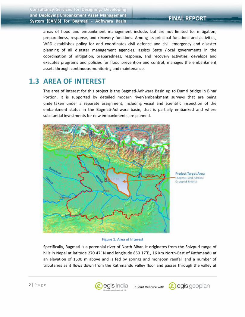
1.3 AREA OF INTEREST The area of interest for this project is the Bagmati-Adhwara Basin up to Dumri bridge in Bihar
Portion. It is supported by detailed modern river/embankment surveys that are being
undertaken under a separate assignment, including visual and scientific inspection of the
embankment status in the Bagmati-Adhwara basin, that is partially embanked and where
substantial investments for new embankments are planned.
Figure 1: Area of Interest
Specifically, Bagmati is a perennial river of North Bihar. It originates from the Shivpuri range of
hills in Nepal at latitude 270 47’ N and longitude 850 17’E., 16 Km North-East of Kathmandu at
an elevation of 1500 m above and is fed by springs and monsoon rainfall and a number of
tributaries as it flows down from the Kathmandu valley floor and passes through the valley at

3 | P a g e
FINAL REPORT
In Joint Venture with
FINAL REPORT
Chovar. The river is fed by a number of tributaries originating at Mahabharat and in the Chure
Range before it reaches the Terai at Karmaiya. The Bagmati River Basin, based on morphology,
land-use etc., can be divided into different sub-basins viz. Upper Bagmati, Upper Middle
Bagmati, Lower Middle (Terai) Bagmati and the Lower Bagmati (Terai) sub basin. The total area
of the Basin within Nepalese territory is about 3638 km2 and enters Indian Territory at about 2.5
kms. Upstream of Rly. Bridge No.89 at Dheng Bridge. Its total catchments area up to its outfall in
the Ganga is 13,424 sq.kms. and total river length is 589 kms. Bagmati is embanked on both
sides in between Khoripakar and Kalanjarghat to contain the shifting river course.
A network of about 10 channels called ADHWARA GROUP interconnected with each other is of
special feature in the drainage of Bagmati catchment. The Darbhanga‐Bagmati drains the
Adhwara group of rivers as Adhwara, Jamura, Mohini, Khiroi, Hardi, Rato, Dhaus, Jamuni, Bighi
etc. Adhwara group of rivers originate from the foot hills of Himalayas in Nepal and join together
to form two distinct drainage channels The combined channels flowing southwards, finally fall
into the Bagmati just above Hayaghat Bridge. The total catchment area of these rivers at their
outfall in Bagmati is 4,962 sq.kms. out of which 2,365 sq.kms. is in Nepal These two channels
join together at Ekmighat, and after the confluence with Darbhanga‐Bagmati, the river Bagmati
is commonly known as Karen. The reach between Kalanjarghat and Hayaghat is relatively stable
and is embanked on both sides from Surmarhat to Hayaghat. The last reach of the river Bagmati,
from Hayaghat to Khormaghat, is the longest reach of 191 km and is embanked on both sides,
on the left bank from Hayaghat to Phuhia and on the right bank from Hayaghat to Badlaghat,
since 1951. After Badlaghat, the river flows eastward and outfalls in the river Kosi.
The total catchment area of the basin is about 14,384 Sq Km, with 6500 Sq Km in Bihar. Out of
the total length of 597 km, 195 km lies in Nepal and the remaining portion in India. Flooding is
mainly caused by the intense rainfall over its catchment that generates high volumes of run‐off,
which spills into the riverbank or breaches the embankment. The average annual rainfall of the
catchment area is more than 1200 mm, mostly distributed between June and September.
1.4 THE NEED FOR DEVELOPMENT OF EAMS Flood management in Bihar is handled by WRD who are responsible for providing relevant
guidelines and protocols to the various flood managers and field personnel. To augment the
flood management, GoB in partnership with Word Bank funding was keen on the speedy
implementation of Flood Management Implementation Support Project Phase II, which would
improve flood management in the State. This follows and builds on the previous phase in which
the Bank, under a previous DFID-financed grant, supported Bihar in initiating a Flood
Management Information System (FMIS) Cell, aimed to generate and disseminate timely and
customized information to move the sector agencies from disaster response to improved
disaster preparedness and to effectively support flood control and management in the flood-
prone areas of the State. A variety of materials related to the status of floods in Bihar were

4 | P a g e
FINAL REPORT
In Joint Venture with
FINAL REPORT
produced using remote sensing and geographic information systems (GIS) techniques. There is
an opportunity with Phase II to build on this to improve GoB capacity to use state-of-the-art
forecasts and to enhance last-mile connectivity for flood preparedness and information
management.
To further bolster the use of modern GIS technology, a need was felt to design and develop a
web based application tool that would integrate and provide on-line access to all the relevant
data needed on embankments, which are currently in different forms and scattered across the
WRD offices together with the inspection data. EAMS would support development of an
Embankment Safety Programme, by periodically monitoring embankment profile, physical
status, and river 4modelled4. It would integrate operational use of past and current satellite
imagery to identify vulnerable reaches, by closely monitoring the changing river course and
consequent pressure on the embankment, bank erosion and deteriorating or less effective bank
protection and river training works. It would assist in checking freeboard requirements against
4modelled flood stage to avoid overtopping which has been reported in past years.
Embankment inspection data from geological and geophysical methods, periodic visual
inspection reports by field offices and communities along the embankment on the physical
status of embankments would assist in evaluating structural safety. It would assist WRD in
rationally locating vulnerable reaches from hydraulic and structural aspects, and make available
relevant data for subsequent detailed design by field units. Embankment safety would be
certified as per standard protocols.
The need for the design and development of EAMS is highlighted below for easy assessment of
the software application:
1. Provide a web based GIS solution that will integrate and provide on-line access to all the
relevant data needed on embankments, which are currently in different forms and scattered
across the WRD offices together with the inspection data that will be generated by using the
PC Tablets as per the Inspection Check List.
2. Provide user based access to relevant flood managers and WRD personnel throughout the
state.
3. Continuously monitor the status and safety of embankments and rationally assess the need
and nature of embankment maintenance, anti-erosion works or flood fighting works to
protect the embankment and the downstream habitations.
4. Provide relevant information for embankment maintenance and strengthening of existing
embankments, planning new embankments and prepare schemes for repair/maintenance of
the embankments in particular reaches.
5. To train relevant field based engineers / personnel in the collection and integration of field
based data of embankments through periodic visual inspection reports by field offices and
communities along the embankment on the physical status of embankments would assist in
evaluating structural safety.
5 | P a g e
FINAL REPORT
In Joint Venture with
FINAL REPORT
1.5 SCOPE OF WORK The scope of work for the consultancy is divided into four major categories. These are as
follows:
1. Design and development of Embankment Asset Management System.
2. Preparation of database, management functional modules and integration in EAMS.
3. Development of Users’ Manual, Technical Reference and Training.
4. Recommendations for sustainable effective use of EAMS.
Please refer to Final Inception Report’s – Section 1.3 Scope of Services as per the TOR for the
detailed scope of work. Based on the scope of work it will be possible to develop an enterprise
database design that will provide FMISC the capability to integrate both spatial and non-spatial
information. This database design supports WRD’s requirement for maintenance and inspection
and further strengthens new initiatives and integration with similar decision support software
tools under preparation. It will have the capability to integrate spatial information related to
river morphology, real-time hydrologic data and flood forecast models. Legacy data, existing and
new embankments drawings and plans, floodway maps, geotechnical reports, maintenance
reports, inspection reports, operation and maintenance manuals, flood fighting reports, models,
and technical studies would be made readily available to users of EAMS.
EAMS will also provide its users database management functions like alerts and reports, and
support relevant functions like providing data on locations and required relevant embankment
profile, river morphology and other data. While detailed design of flood protection works is not
planned within the EAMS environment, the consultancy includes the establishment of
administrative protocols for data input and editing to provide data integrity and quality control.
To support long term management and maintenance of this database, EAMS would be
supported by modern and latest GIS standards, and a comprehensive data management plan
that dynamically captures embankment and river related details from both digital (including
other information systems) and hard copy sources.
1.6 CONTENT OF THE FINAL REPORT The document is intended to provide an overview of the project and each of the
different chapters provide details of the work accomplished and relevant information. It
is meant to be read by key Officials of the FMISC and other stakeholders, and hence it
has to provide them a concrete idea about EAMS as a solution.
This document is divided into various chapters in order to provide an organised view of
the Final Report.

6 | P a g e
FINAL REPORT
In Joint Venture with
FINAL REPORT
1. Chapter 1: Introduction
This chapter introduces the project and provides a background to the project,
mission of the WRD, study area, need for the design and development of EAMS, and
scope of work.
2. Chapter 2: EAMS Tasks
This chapter provides information related to the various tasks as per the Scope of
Work. Each of the tasks is defined and highlights of the tasks are provided for better
understanding of the project.
3. Chapter 3: EAMS Modules and Tools
This chapter provides information related to the various EAMS modules and tools
that are provided as part of the consultancy and as per the scope of work.
4. Chapter 4: EIS Tools
This chapter provides information related to the various EIS modules and tools that
are provided as part of the consultancy and as per the scope of work.
5. Chapter 5: EAMS Maintenance
This chapter provides a maintenance plan and enumerates various tasks that need
to be accomplished so as to sustain the proper functioning of EAMS. It also identifies
key personnel and stakeholders that may influence the functioning of EAMS and
includes training plans, data update and exchange, relevant documentation, data
backup and the importance of a dedicated infrastructure facility within FMISC.
6. Chapter 6: Security Levels
This chapter provides relevant security issues with respect to EAMS Web
Administration, changes in verification workflow and changes in business workflow.

7 | P a g e
FINAL REPORT
In Joint Venture with
FINAL REPORT
2 PROJECT TASKS AS PER SCOPE OF WORK
The tasks and work schedule for completion of the EAMS Project has been divided into four
sections as per the scope of the project. These sections are as follows:
1. Design and development of Embankment Asset Management System.
2. Preparation of database, management functional modules and integration in EAMS.
3. Development of Users’ Manual, Technical Reference and Training.
4. Recommendations for sustainable effective use of EAMS.
Within each of these sections, the tasks and work schedule will be explained in brief with
emphasis on the tasks at hand, the methodology adopted and the learning from each of these
tasks. The methodology adopted for completion of all tasks will follow the below shown
workflow.
Figure 2: Approach, methodology and workflow adopted for design and development of EAMS

8 | P a g e
FINAL REPORT
In Joint Venture with
FINAL REPORT
2.1 TASK 1: DESIGN AND DEVELOPMENT OF EMBANKMENT ASSET MANAGEMENT SYSTEM This tasks consists of start-up and project initiation phase of the project. The main objectives of
this phase were as follows:
1. To review international and national in the design and development of EAMS and to identify
possible approaches in the design and development of the database similar to the database
developed by USACE.
2. Conduct a preliminary user needs study that will focus on understanding user needs and
expectations, review of data and its availability and identifying system requirement
specifications.
3. Prepare a project plan for project implementation and identify the risks and finalise the
same in consultation with FMISC.
2.1.1 Review of International & National Experience
To understand the development of EAMS, it was necessary to review both international and
national best practice adopted by various agencies and organisations with special emphasis on
the NLD developed by USACE. This review was designed to provide points in the design and
development of EAMS.
1. National Levee Database (NLD) by USACE.
The USACE has developed one of the most comprehensive databases of Levees within the
contiguous United States. This database contains information to facilitate and link activities,
such as flood risk communication, levee system evaluation for the National Flood Insurance
Program (NFIP), levee system inspections, flood plain management, and risk assessments. It
is a dynamic database with ongoing efforts to add levee data from federal agencies, states,
and tribes and provides a searchable inventory of information about levees, location and
condition of levees and floodwalls, displayed in an easy-to-use map interface, as well as
reports, inspection summaries, and other records. The map-based interface is easy to use.
One can enter a zip code and receive a listing of levees nearby, or see a map showing the
levee and the levied area. User can also view the levee data in combination with other
Geographic Information Systems data, including real-time data from sources such as stream
gauges and weather radar.

9 | P a g e
FINAL REPORT
In Joint Venture with
FINAL REPORT
Figure 3: Map Interface of NLS developed by USACE
Figure 4: NLD GIS database Layers

10 | P a g e
FINAL REPORT
In Joint Venture with
FINAL REPORT
The NLD also provides an inventory of all the assets that make up the levee database that is
useful for developing the EAMS database. Please refer to the figure for the different assets
that make up the embankment database.
2. California Levee Management System.
Based on the lines of NLD various states within the United States developed their own levee
database. California was one of the pioneering states that adopted the NLD database and
developed CLASIS a web based GIS map interface. The California Levee Database (CLD) is
collated from various agencies/ organisations to accomplish the following:
NLD Surveyed Levee Centerlines.
Levee Data Model was developed based on inputs from various agencies.
Worked with the State’s Plan of Flood Control (SPFC).
Data collection for non-project levees included data collection of levees and levee-like
structures;
Establishing relationships with agencies for exchange of data
Improve levee alignment of non-project levees
Integrate data from Midterm levee inventory (MLI) in to the California levee Database
(CLD), adjust/Improve alignments of non-federal levees
Refine data exchange process to streamline data transfer.
Figure 5: GIS Data Displayed for CLASIS – Levee Centrelines Overlaid on Aerial Photos

11 | P a g e
FINAL REPORT
In Joint Venture with
FINAL REPORT
3. European Efforts: Flood & Levee Management Solutions
In Europe Levee management systems are highly advanced especially in countries close to
the sea. The economies of many countries depend upon the management of thousand of
levees, dams, canal systems and involve collection of hydrological and meteorological data.
Netherlands Flood and Levee Information systems are one of the most advanced systems of
flood control, where the emphasis is to tame the sea through a network of dykes and
levees. They have developed advanced modelling solutions like the Rapid Engineering
Assessment of Levees (REAL®) that provide tools for modelling 3D subsoil models and 3D
groundwater models from geo data.
Figure 6: Results from a safety assessment in REAL
A similar system is also available in France who have developed DIGUE, a GIS database
solution that is available for use in levee management system. It enables the levee manager
to enter new and update existing database based visible information and disorders on
specific field observation cards. The use of modern GIS database management systems,
review and update existing data using both field based data collection and satellite
interpretation, and integrating real-time hydrological and meteorological data are some of
the hallmarks of the French Levee Management solution.
4. Flood & Levee Management Solutions in Asia.
While Integrated Flood Management is being practised by many Asian countries, GIS or
geospatial tools are only recently being used to manage flooding, and flood modelling. It is
only recently that the use of GIS and various hydraulic models like MIKE11 & MIKE21 are

12 | P a g e
FINAL REPORT
In Joint Venture with
FINAL REPORT
being employed to determine the extent, depth and duration of flooding. Modern intelligent
systems as adopted by the Yellow River Conservation Commission, Ministry of Water
Resources, China is a case in point.
A map based dashboard provided the YRCC real-time information relating to the flood
situation. AGT International provides the YRCC with an advanced, comprehensive,
integrated water management solution, by monitoring the overall dike system and focusing
on:
Protects near population, industry and agriculture
Sustainable solution for future advancement in technology
Cost-effectiveness
Figure 7: Actionable Intelligence
The advantages of such a system dashboard provided YRCC to provide
Insights and Actionable Intelligence for authorities
Monitoring of erosion and micro-stability
Early warning and flood prediction
Real time, automated insight to the status of dikes
Better resource planning for maintenance
Reduced need for strength testing
Unified Situation Awareness Picture (USAP)
Emergency early warning and decision support
Link to relevant authority for flooding and timely evacuation

13 | P a g e
FINAL REPORT
In Joint Venture with
FINAL REPORT
5. National and International Learning Experience
The learning from the literature with regard to international experience narrated in this
chapter points out GIS to be a tool for managing (storing, retrieving and enhancing the value
of) all existing and future data related to levee/embankment management. Some of the
learning is as follows:
a) Decision Support Tool
Provide a spatial decision support system aiding levee/ embankment / flood managers
in condition assessment.
Data can be localised spatially, but also provide a spatial decision support system aiding
levee managers in condition assessment.
Provide a decision-making aids for levee managers taking into account a risk analysis on
a levee system scale.
Data specialisation and methods suited to the great length of levees in operation.
b) Multiple Data Sources
Integration of multiple data sources is possible to create a centralised database
repository of information.
GIS based investigation / assessment/ inspection can provide the centralised database
with most updated field conditions.
An exhaustive Levee/ embankment database can be created.
Various data collection tools have been used for creating or updating the levee/
embankment databases. These tools are: GPS, LIDAR, ground total stations survey, field
data collection using mobile solutions, etc.
Automated reporting systems can be developed that will enhance the existing database
and keeping it updated at all times.
c) Web Based Design
Many organisations are using web based embankment/ levee information to aid
decision makers in managing not only the assets within the embankment but also
provide relationships between each of the layers of information.
Both open systems and COTS based solutions have been used for creating a web based
solution on multiple operating systems.
d) Advanced Spatial Analysis
Integration of various modelling tools can be integrated to provide advanced spatial
analysis.
Connectivity to various sensors also provides real time data for embankment/ flood
managers.
Specific flood analysis tools can be developed that will provide users intelligent solutions
and actionable intelligence.

14 | P a g e
FINAL REPORT
In Joint Venture with
FINAL REPORT
The approach and indicators discussed here were the guiding sources during development
and designing of EAMS for Bagmati- Adhwara Basin, The system will be developed on the
lines of USACE’s National Levee Database.
2.1.2 Identification of Key Input Data & Existing Data Assessment
Based on the literature review, understanding of different layers of information required for the
design and development of EAMS, it was important to - identify the key data layers required;
assess available spatial and non-spatial data and identify the missing gaps; status of available
data – both spatial and non-spatial.
Identify the key data layers required.
The key data layers identified in the design and development of EAMS was based on the
data layers as identified during the literature review. Based in SDSFIE data layers as is used
by the USACE, the EAMS contains similar data layers though customised as per the user
requirements. These key data layers identified are given in the table below:
S. NO KEY DATA LAYER DATA LAYER DESCRIPTION
1 Base Database This includes satellite data and administrative units for the area of interest. High resolution satellite with spatial resolution of 1m to 2 meters is recommended so that various assets can be overlaid and seen on the EAMS solution. The administrative database needs to be vector format and should include GIS data layers such as Districts, Blocks and Villages of Bihar.
2 Basic Infrastructure Relevant GIS data layers such as Roads, Railways, Power lines, pipelines, etc will form the basic infrastructure
3 Base Hydrological Database
This refers to data related to river/streams, drainage and river basins.
4 Embankment Database
This refers to embankment centrelines, start and end points, L & C profile sections and embankment history.
5 Embankment Based Hydrological Database
This include databases related to embankment data layers like Hydrological Observation Stations,

15 | P a g e
FINAL REPORT
In Joint Venture with
FINAL REPORT
S. NO KEY DATA LAYER DATA LAYER DESCRIPTION
embankment breach points, encroachments etc that consist of both spatial and tabular data.
6 Flood Hazards Database
These relate to data that provide information about major flood events, inundation maps, flood prone zones, and flood damage database.
7 WRD Infrastructure Asset Database
An inventory of available WRD assets in the form of bridges, culverts, flood office locations, barrage, weirs etc that are used for flood and embankment protections also need to be identified.
8 Hazard Resource Profile
These include both GIS and tabular data that consist of crop areas, LULC, Soil types, forests, vegetative cover etc.
Table 1: Identification of Key Data Layers As per SDSFIE of USACE
Comprehensive lists of identified data layers are given in the Final Inception Report section
3.1 Key Input Data Requirement and Sources.
2.1.3 Preliminary User Needs Assessment
A preliminary User Needs Assessment (UNA) was conducted to understand the quantum of work
required for conducting the final system requirement study. The findings are provided below in
brief. A comprehensive UNA is provided in Chapter 2 of the Final Inception Report.
1. Existing Flood Management Program at FMISC.
With the help of World Bank, the WRD formed the Flood Management
Improvement Support Cell (FMISC).
The main task of FMISC was to provide timely information to flood managers
through the use of remote sensing / GIS and modelling techniques.
They were also responsible for creation of digital GIS data with 11 districts of North
Bihar and South Bihar which were the most flood prone areas.
FMISC collates information related to the latest satellite data and inundation maps
along with observed rainfall, 3 day advance rainfall forecast, river gauge level, trend
forecast of CWC and state gauge sites.
16 | P a g e
FINAL REPORT
In Joint Venture with
FINAL REPORT
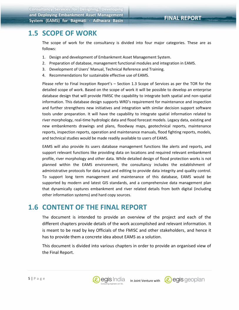
2. Staffing Pattern at FMISC.
FMISC falls under the Directorate of the Bihar WRD and the salient feature of the staffing
pattern are as follows:
FMISC is headed by a Joint Director who is ably assisted by two Deputy Directors.
While most of the personnel are engineers by profession, there are others who are
responsible for providing remote sensing / GIS and modelling techniques.
World Bank has also employed specialists for Flood Management and Embankment
Management who provide support for flood management.
It also has support staffs which provide assistance in running of the organisation.
Figure 8: Staff at FMISC

17 | P a g e
FINAL REPORT
In Joint Venture with
FINAL REPORT
3. Field Data Collection and Data Transfer
Field data is also collected by the field support staff who are attached to the various CE
circles and help in the management of floods within the state. The salient features of field
data collection and data transfer are as follows:
Satellite and inundation maps are supplied by NRSA and downloaded from ftp site.
Field data related to rainfall, Gauge & discharge, silt, water quality are being
collected by the field formations of Indian meteorological Department, Central
Water Commission and state Water Resources Department respectively,
Data is processed and validated at FMISC for further use.
4. Infrastructure , Amenities and Facilities
Presently, FMISC has limited infrastructure facilities and amenities that support their RS/GIS
functions. The existing system architecture is depicted below.
Figure 9: Existing System Architecture.
5. Ongoing and Proposed projects
There are many ongoing and proposed projects at FMISC that are being initiated by the
WRD within the Area of Interest (AOI). A comprehensive information related to ongoing and
proposed project are mentioned in the Final Inception Report: Section 2.5 Ongoing &
Proposed Projects. The salient features of these projects/ schemes are as follows:
Various projects and schemes within the Bagmati – Adhwara river basins are under
implementation or proposed.
The main emphasis is towards the strengthening and raising of existing
embankment, construction of new embankments.

18 | P a g e
FINAL REPORT
In Joint Venture with
FINAL REPORT
Improvement and construction of these embankments are sanctioned by the
Technical Advisory Committee (TAC) and Ganga Flood Control Commission (GFCC).
Random site visits were initiated that included inspection of existing embankments,
vulnerable points, and physical conditions of embankments and assets deployed.
6. Risk Assessment
For designing, development and deploying of the Embankment Asset Management Solution
(EAMS) for Bagmati-Adhwara Basin, the following were the risks identified:
Accuracy of the data whether spatial or non-spatial is an important aspect and
influences the accuracy of the results.
The availability of time series data provides is also important and its shortage will
influence real-time predictions.
Data need to be processed before integration with the main database.
Adequate measures need to be in place so as to cover all possible threats, including
information theft, by either preventing it or having a reaction plan in place if it
occurs thereby restricting the loss.
2.1.4 List of Deliverables In Task 1
The list of deliverables in Task 1 is given in the table below as per the defined scope of work.
S.NO TASKS DELIVERABLE
1 Review of International and notational experience
INCEPTION REPORT
2 Conduct inventory of existing and expected future data
3 Conduct User Need Survey to define Functionality of EAMS
4 Review of data of other constituency ( modeling , River survey, spatial data )
Table 2: List of Deliverables in Task 1

19 | P a g e
FINAL REPORT
In Joint Venture with
FINAL REPORT
2.2 TASK 2: PREPARATION OF EAMS DATABASE, MANAGEMENT FUNCTIONAL MODULES AND INTEGRATION IN EAMS. The second phase of the project consists of tasks where the main objectives were as follows:
1. Conduct a comprehensive System Requirement Study along with System Design
Document.
2. Data collection, creation, update of existing spatial and non-spatial data so as to
integrate with the database model being developed as part of the EAMS project.
3. Creation of a database model that will be able to handle the various functionalities
as identified in the SRS and System Design documents.
4. Identify the functional modules of EAMS and its integration.
2.2.1 Comprehensive SRS and SDD
Based on the review of international and national literature in the development of an enterprise
solution and also the initial user needs assessment a comprehensive System Requirement Study
and System Design document were created that would fulfill the following objectives:
1. System Requirement Study
Define the general descriptions of current embankment asset management systems;
Identify the various inputs for the proposed Embankment Asset Management System
(EAMS);
Functional requirements of EAMS;
System capabilities, conditions, and constraints;
System interfaces.
2. System Design Document
System architecture
Data Storage Design
Human machine Interface
External Interfaces
System Integrity Controls
2.2.1.1 System Requirement Study
The primary objective of EAMS is to provide a web based easy to use map interface that will
allows various stakeholders to
(i) Provide a spatially oriented mapping application to map and manage existing
embankment assets.

20 | P a g e
FINAL REPORT
In Joint Venture with
FINAL REPORT
(ii) Provide a decision support information management tool for decision making.
The aim of the SRS is to understand and develop a decision support tool that will allow various
stakeholders to manage existing assets along embankments, collect and integrate real-time data
from the field, and provide flood managers and other stakeholders’ up-to-date information
quickly and efficiently. The main objective of the SRS was to provide for the following:
Integrate and provide on-line access to all the relevant data needed on
embankments, which are currently in different forms and scattered across the WRD
offices.
With the help of hand held android based devices and EAMS embankment project
managers will be able to provide regular Embankment upkeep and development by
periodically monitoring embankment profile, physical status, and river behaviour.
EAMS would integrate operational use of past and current satellite imagery to
identify vulnerable reaches, by closely monitoring the changing river course and
consequent pressure on the embankment, bank erosion and deteriorating or less
effective bank protection and river training works.
EAMS would assist in checking freeboard requirements against modelled flood stage
to avoid overtopping which has been reported in past years.
Embankment inspection data from geological and geophysical methods, periodic
visual inspection reports by field offices and communities along the embankment on
the physical status of embankments would assist in evaluating structural safety.
EAMS would assist WRD in rationally locating vulnerable reaches from hydraulic and
structural aspects, and make available relevant data for subsequent detailed design
by field units.
Embankment safety would be certified as per standard protocols.
The SRS is divided into the multiple sections to help understand the requirements of designing
and developing EAMS. These points are further elaborated with bulleted points to better
understand the requirements and the System Requirement Specification document provides a
complete and elaborated description of the EAMS solution.
1. General descriptions of current embankment asset management systems.
Presently embankment asset management is undertaken by the WRD personnel by
various nodal agencies like CWC/GFCC, Flood monitoring cells, CE circles.
All these nodal agencies conduct their activities based on Flood Management SOP or
Barh Gashti Niyamavali which is published by each of the CE circles.
All activities are coordinated with the help of an annual calendar that is
published in the SOP and include workflows, field data collection and reports
for the maintenance, prioritization & monitoring, pre/ post monsoon,

21 | P a g e
FINAL REPORT
In Joint Venture with
FINAL REPORT
corrective actions and planning of new structures. A typical annual calendar
is shown in the table below for further reference.
S.No Work Description Responsibility Tentative Dates
1 Joint Inspection Field Engineers/
Anti Erosion Committee
17 September
21 – 23 September
2 Submission of Report to TAC Chief Engineer/ Field Engineer 1 October
3 TAC Evaluation Committee members from WRD 8 – 14 October
4 Recommendation presented
to SRC TAC 17 October
5 Technical evaluation by
GFCC/ State/ WRD SRC 18 October
6 Implementation Phase Chief Engineer/
Field Engineers 7 January
Table 3: A Typical Calendar for Implementation of Schemes (SOP, 2013).
Field data is collected throughout the year but is most active during the flood
season where information relating to the integrity of the embankments is critical for
managing floods.
Daily registers are maintained at the field offices and typically include duty registers,
job registers, site order registers, gauge registers, rainfall registers, flood breach
registers etc.
Schemes and proposals are typically presented to the TAC during the post-flood
season where the integrity and condition of the embankment are evaluated and
further action enumerated to ensure safety from flooding.
There exist little or no means to represent spatial information and typically paper
printouts provided by FMISC are in use.
A user needs workshop was also conducted at WALMI, Patna and CE Office,
Muzaffarpur where the main aim was to interact with various stakeholders. The
objective of the workshop was also to introduce EAMS and get feedback relating to
the following:
o Understand the importance and need and scope of EAMS.
o Assist in firming the needs for which the EAMS is to be designed.

22 | P a g e
FINAL REPORT
In Joint Venture with
FINAL REPORT
o Develop the final Inspection Checklist for designing the Embankment
Inspection System (EIS).
o Plan operational scenarios to effectively maintain and use EAMS.
Figure 10: A Typical Snapshot of the Cover Page of the Proposal for Anti-Erosion Works
During the workshops various points emerged that was useful during the
development of EAMS. Please refer to the System Requirement Specification
document, Section 2.4 User Needs Workshop.
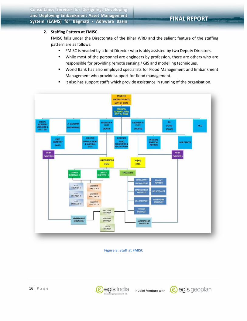
2. Inputs for proposed Embankment Asset Management System (EAMS).
Both spatial and non-spatial data were identified as the primary input data for the
design and development of EAMS.
Data was to be collected from various sources and integrated and included various
data layers.
23 | P a g e
FINAL REPORT
In Joint Venture with
FINAL REPORT
Figure 11: Integration of various data layers from multiple data providers.
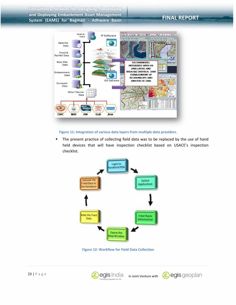
The present practice of collecting field data was to be replaced by the use of hand
held devices that will have inspection checklist based on USACE’s inspection
checklist.
Figure 12: Workflow for Field Data Collection

24 | P a g e
FINAL REPORT
In Joint Venture with
FINAL REPORT
Planning maintenance schedule, prioritization and monitoring of the flood fighting
works be carried out as per Standard Operating Procedure (SOP) and further
augmented by EAMS mapping interface.
Bothe corrective and planning of new flood protection works can also be enhanced
through the user of EAMS which will provide spatial information especially during
the post flood season.
3. Functional requirements of EAMS.
The functional requirements of EAMS was based on the following aspects:
o Database integration workflows
o GIS database design with respect to spatial and non-spatial databases
o Tools of EAMS
o Data Collection Tools
o Design of web based GIS tool
o Spatial analysis performed on the EAMS
Integration of various components is an integral part of design and development of
enterprise web based services. Some of the points that was taken into consideration
are as follows:
o Emphasis on the standardisation of various data from different sources so
as to facilitate data integration.
o The field data collected using hand-held devices are important since vital
information needs to be integrated into EAMS quickly and efficiently.
o A system of verification and approval needs to be in place that will allow
only authorised personnel to integration only the relevant information so as
to maintain data integrity.
o Database management is an important aspect of data integration and it was
recommended that they be organised within a system of catalogues and
indexes. This will not only facilitate data storage, retrieval, maintenance
etc but conforms to the requisite quality assurance and control.
S.No DATA LAYER CATEGORIES
1 BASE DATABASE
(i) Satellite data
(ii) Administrative Units
(iii) Basic Infrastructure
(iv) Base Hydrological Data

25 | P a g e
FINAL REPORT
In Joint Venture with
FINAL REPORT
S.No DATA LAYER CATEGORIES
2 HYDROLOGICAL DATABASE
(i) Hydrological Data Layers
(ii) Flood Hazard
3 EMBANKMENT DATABASE
(i) Embankment Data Layers
4 WRD INFRASTRUCTURE ASSET DATABASE
(i) WRD Infrastructure
5 NATURAL RESOURCE PROFILE DATABASE
(i) Land use
(ii) Soil
(iii) Forest/Vegetation
Table 4: List of Data Required for EAMS Development
System architecture forms the foundation of the EAMS solution and mainly
influenced by four basic components which are as follows:
o Data collection and integration.
o Understanding of documenting design aspects.
o Identifying the various spatial and non-spatial data layers.
o Defining spatial behaviour with the help of entity relationships between
various data elements.
Another important factor in the development of EAMS is the design and
development of an enterprise server architecture that will deliver an end-to-end
system in the form of geospatial data services, tools and applications.
Access control to the various web services is another important aspect that
integrates well with the seamless workflow of an enterprise workspace and
allows multiple users to access web services based on user access control.
Avoidance of data duplication and improving the currency of data ensures
up-to-date information.
Establishing and implementing database standards in the development of
data, variables, and models will insure correct geographic registration,
relationships between datasets, and maintenance of data quality.

26 | P a g e
FINAL REPORT
In Joint Venture with
FINAL REPORT
Sharing of GIS information and improving the field data collection process
are important issues that need to be handled effectively so that sensitive
data is secure and is used for the purpose it is meant to be used.
It is recommended that the tools provided and outputs from EAMS will allow
users to view existing embankment assets on a web based solution and
analyse data to get the requisite outputs.
A hand-held android based inspection tablet / phablet/ phone is
recommended that will help users collect field data based on USACE’s
Inspection data format.
Figure 13: Hand-held Android Based Embankment Inspection Tool to collect field Data.
Web based tools provided within EAMS will provide users with a GUI based
data viewer, spatial tools for data analysis, tools for report generation, and
maintenance features.

27 | P a g e
FINAL REPORT
In Joint Venture with
FINAL REPORT
Figure 14: Web Interface of EAMS
While field data and data update will be done on pre-defined intervals, a system of
protocols and compliance reporting will be key to data update and up-to-date data.
4. System capabilities, conditions, and constraints.
For easy and efficient visualization, analysis and exploration of embankment
assets information it is important to define system capabilities, conditions
and constraints that will influence the design and development of EAMS.
Some of its features are as follows:
o GUI based interactive tools will be provided and will be developed using the
latest HTML5 technology.
o As per the requirement of EAMS, the web interface will also have tools for
data entry and reports integration especially field data. Various forms as is
in use will be provided for users to maintain records.
o Based on a comprehensive comparison of hardware and software, it was
decided that ESRI server technology and upgrade of existing hardware will
be used to serve EAMS to various stakeholders.
Thick and thin server technologies are proposed to serve different GIS services to
various stakeholders. This will be based on ensuring the following:
o Provision of internet connectivity between various facilities.
o Providing a reasonable response to user action.
o Providing secure and integrated solution.
o Designing input validation strategies that will ensure secure field inspection
reports and web based services.

28 | P a g e
FINAL REPORT
In Joint Venture with
FINAL REPORT
o Partitioning of web sites into open and restricted areas.
o Providing a system of effective user account management using latest
internet technologies and best practices.
o Designing and developing effective user authentication and authorization
strategies.
Providing a system of data protection, user sessions, handling of errors and
exceptions, etc.
Evolving a system of efficient workflows in the operation of EAMS through
o Provision of online feedback/ suggestions.
o Providing online menus and manuals.
o Computerised maintenance driven by performance
o Defining policy and regulations.
5. System interfaces.
Based on USACE’s Inspection Checklist, an android based hand-held solution will
equip the field personnel at various WRD locations to collect field data.
A GIS based web interface will be provided to users for the preparation and analysis
of both spatial and non-spatial information.
All stakeholders will be trained in the use of embankment management, flood
monitoring, scheme assessment etc so as to optimally use EAMS.
The design of EAMS takes into consideration
o The establishment of a secure communication between different
stakeholders.
o Employ an integrated system approach.
o Adapt critical infrastructure in response to dynamic conditions and practice.
o Update of existing spatial and non-spatial database.
2.2.1.2 System Design Document
The conceptual, logical and physical design elements have been designed so as
provide decision makers tools to improve operational efficiency and enhance
decision making capability.
The design document details three elements, namely, the system architecture,
functional requirements, and interfaces between different interfaces.
It provides both developers and users of EAMS comprehensive architectural design,
human interface use-cases, database model and logic, web based services, various
functionalities, workflows, prototypes, etc.

29 | P a g e
FINAL REPORT
In Joint Venture with
FINAL REPORT
Figure 15: System Architecture
The design of the system architecture was based on integrating various architectural
components and takes into consideration system hardware upgrades, software
architecture and network characteristics. It also takes into consideration user
interface and capacity planning tools (CPT) that help define the system architecture.
The system hardware and software architecture consists of the following:
o Client hardware for conducting GIS, database and web services
functionalities.
o A centralised hardware that will serve various software components.
o Network characteristics that will provide the accessibility to different users
within FMISC and different WRD facilities located around the AOI.
o Comparatively, the software solution consisted of a centralised GIS and
database servers that will service EAMS user requirements.
Data storage was in three basic formats – vector data organisation, raster data
storage and non-database storage. These will be supplemented by designing and
integrating the system tables by developing a geo-database model that with
dynamic coded value domains and entity relationships between different data
storage types.
The geo-database model consists of multiple data layers and is inclusive of both
spatial and non-spatial data layers.

30 | P a g e
FINAL REPORT
In Joint Venture with
FINAL REPORT
Figure 16: Geodatabase Model
The functional modules identified within EAMS relate mainly to the tools and
functionalities that were available from within EAMS and EIS.
Both module functionalities are elaborated in the next chapter for better
understanding of EAMS.
Use cases diagrams captures the various business processes carried out within
EAMS. It must be reiterated that the solution is dynamic and new use cases
developed based on the experience and usability of the solutions provided.
Figure 17: A sample Use Case Scenario
The design of the EAMS solution has been developed taking into consideration its
interaction with third party solutions.

31 | P a g e
FINAL REPORT
In Joint Venture with
FINAL REPORT
To ensure that the EAMS solution’s integrity is not compromised, lost, misused or
modified both internal and external user access has been restricted and is
elaborated in Chapter 4: System maintenance and Chapter 5: Security Issues.
2.2.2 Data Standards, Data Collection, Creation, Update of Existing
Data
Spatial information - images and maps, forms the foundation and basis for planning and
implementation of developmental activities; infrastructure development; disaster management
support; environmental monitoring; natural resources management; business geographics and
many other national activities. Guidelines as provided by the Government of India and
implemented by Survey of India ensures that the spatial data follow a standard relevant details
of maps such as scale, information content, date of data capture, price, mode of data
dissemination.
This section provides information related to the following:
1. Geospatial Data Submission – Standards & Regulations.
2. Data Collection Methodologies adopted.
3. Creation and update of existing spatial and non-spatial data.
4. Integration of data into EAMS.
2.2.2.1 Geospatial Data Submission – Standards & Regulations
It is recommended that FMISC follow the National Data Content Standards (NSDI) designed
to facilitate the sharing of Geographic Data Sets (GDS). FMISC will acquire, process,
store, distribute and improve utilization of spatial data as per the procedures set by
NSDI and will be a gateway for providing spatial data to WRD and its associated
agencies.
FMISC need to be coordinate, develop and maintain data quality and usefulness of
existing and new data. Data submission needs to be primarily governed by the
following:
FMISC have chosen to adopt ESRI as the core standard for all GIS formats;
FMISC reserves the right to reject any data supplied by a Data Submitter within 2
weeks of receipt if it does not meet the required standards.
FMISC GIS Section manages the corporate GIS data and is responsible for
disseminating GIS data for its users within WRD and other agencies. It includes a
spatial data warehouse of key datasets.
Any information submitted to FMISC must be consistent with this corporate GIS and
the associated Corporate Data model. It must be easily incorporated into the

32 | P a g e
FINAL REPORT
In Joint Venture with
FINAL REPORT
database by the GIS Section to allow its onward dissemination and use by internal
WRD stakeholders that are seeking to utilise the spatial data;
A number of WRD users and external parties may be reliant on the information
provided by the Data Submitter. This should be understood by the Data Submitter;
Supply of datasets to support collection of data by a third party or consultant
working on behalf of the WRD can be facilitated only with prior written agreement,
including reference to licensing terms for the supply of such information;
WRD considers the supply of supporting information as important as the actual
data. Incomplete supporting information may also result in rejection of dataset
supplied by a Data Submitter.
A comprehensive document “Geospatial Data Submission (GDS) Standards and Regulations”
outlines the following points in detail:
Geospatial data submission requirements.
Data field and data definition which outlines the feature classes, data submission
guidelines, submission of as-built drawings or CAD submissions, and topology rules
Responsibility of FMISC to provide design consultants data submission guidelines
for submitting as-built or CAD drawings, GIS data, attribute capture, etc.
2.2.2.2 Data Collection Methodologies Adopted.
Data for the design and development of EAMS is being collected from a wide variety of sources.
The data collected most often than not need to be processed into a format that will be
compatible with EAMS. The data collection methodologies fall under three basic methodologies.
The SRS document provides these three data collection methodologies in detail. The highlight of
the data collection is as follows:
GIS and satellite data collected from NRSA and Remote Sensing Agencies.
o NRSA provide satellite data at various resolutions to FMISC that will be used
as backdrop for EAMS.
o The GIS data is collected mainly from Bihar Remote Sensing agency, Survey
of India and other similar data producing agencies.
o These GIS data sets need to be processed and then integrated into the
EAMS.
o FMISC has also outsourced data collection to different third party survey
agencies that are responsible to submit the data as outlined in the GDS.
o As-built drawings or CAD drawings are also submitted that relate mainly to
the cross section and longitudinal section profiles of embankments and
rivers. These needs to be further processed and then integrated into EAMS.
o Data is also collected from other decision support systems and mainly
related to flood modelling, inundation maps, etc.

33 | P a g e
FINAL REPORT
In Joint Venture with
FINAL REPORT
Data collected from the field provide a vital link to the health of the embankments.
While field data is presently entered into registers, the EAMS solution will provide
tools that will allow users to enter data into the EAMS and hence can be used
instantaneously. A hand-held android device will also be used for data collection
where data can be uploaded onto EAMS into data formats as defined in the
document Geospatial Data Submission (GDS) Standards and Regulations. The
workflow for data collection is shown in the figure below:
Figure 18: Field Data Collection Workflow
Document data is also collected from a wide variety of sources. The different types
of documents collected are as follows:
o Documents related to the various schemes or proposals that are submitted
to TAC.
o Manuals, SOPs, and other relevant documents from relevant agencies like
GFCC, WRD, CWC etc.
o User manual and other relevant documents that will be useful for various
stakeholders.
2.2.2.3 Data Creation, Update of Existing Data and Integration.
It must be reiterated that data needs to e continually created and then further updated
continuously so as to maintain data currency. As part of the data creation and data update
process the following initiatives were undertaken so as to ensure that the data created and
updated are in line with the standards as outlined in the Geospatial Data Submission (GDS)
Standards and Regulations document. The highlights of the data creation and data update are
follows:

34 | P a g e
FINAL REPORT
In Joint Venture with
FINAL REPORT
CAD or as-built drawings for different profiles have been provided by FMISC during
data collection. These as built drawings are mainly in AutoCAD format and belong to
C/S & L/S profiles of embankments and river..
Satellite data from NRSA and other sources also need to be rectified and projected
in the projection system chosen for EAMS. Various image processing tools are
employed to do the rectification of these satellite imagery and then updated.
GIS data that are continually created and updated as per the requirement of EAMS.
New data from the field are also first verified and then updated as per requirement.
New documents are further added by including the metadata of the document so as
to facilitate quick search.
Workflows for the integration of various types of datasets are provided as part of
the SRS.
2.2.3 Creation of Database Model to Handle the Various
Functionalities
Enterprise GIS design includes a broad range of technology that must play together to
satisfy identified business needs. The processes involved in building a common platform
and establishing a framework that satisfies business needs requires the integration of
various disciplines (Peters, 2014). The better they work together, more productive is the
design. The business logic for providing stakeholders various functionalities and allowing
them to manage embankment assets & provide tools for making informed decisions
rests on the creation and development of a database model that will take into
consideration the following contingencies:
1. The data model should support representation of all embankment related features -
both legacy and present features.
2. The data model should enable the integration of external data.
3. The data model should facilitate the extraction of archived embankment data.
4. The data model should support the storage and display of solutions computed by
third party models.
It must also be reiterated that the design of the database model needs to be kept simple
yet workable and efficient. It needs to be kept flexible enough to integrate datasets as
and when the need arises. The EAMS data model consists of the following components:
1. Base Map Data
2. Basic Infrastructure Data
3. Embankment Features Data

35 | P a g e
FINAL REPORT
In Joint Venture with
FINAL REPORT
4. WRD Infrastructure Assets Data
5. Hydrological Data
6. Natural Resources Data
7. Land use/ Land cover
8. Cadastral Surveys
9. Elevation Data
10. Multi-date Mosaicked Satellite Data
11. Tables
For an effective enterprise-wide Web GIS services, it is essential that spatial and non-
spatial data contents be identified and integrated within the enterprise Geodatabase.
Based on the user requirements and subsequent interactions with the relevant FMISC
officials, the spatial and non-spatial data contents were identified and which will be
made available within EAMS and EIS. This section will provide information related to the
following:
1. Development of the Multi-user Database
2. Spatial & non-spatial data layers.
3. Data structure and data storage.
4. Geodatabase model – Feature Class, Tables, Coded Domains, Relationships.
5. Integration of Data Model with other web based Systems.
Please refer to comprehensive information related to the development of the
geodatabase model as provided in the System Design document in section 3.1.1.
2.2.4 Identify The Functional Modules of EAMS and Its Integration.
The functional modules are provided in the next chapter and also elaborated in Section 4.0 of
the SRS and Section 4.1 Software Detailed Design of the System Design document. The
functional modules were based on the following premises:
Each module within EAMS will have a defined function(s), the conditions under
which it is used (called or scheduled for execution), its overall processing, logic,
interfaces to other modules, interfaces to external systems, security
requirements, etc.
To identify any call routines or bridging programs or Dynamic Link Libraries (DLL)
that integrates the solution with other COTS third party packages.
To develop a handheld field application that will allow field data collectors to
collect relevant data and upload the information. It will detail the workflow,

36 | P a g e
FINAL REPORT
In Joint Venture with
FINAL REPORT
action diagrams, flowcharts, etc.
To define all data elements, record structures, and file structures associated with
module input and output.
To graphically represent each of the modules, its processing logic, flow of
control, and algorithms, using an accepted diagramming approach (for example,
structure charts, action diagrams, flowcharts, etc.)
Data entry and data output graphics; define or reference associated data
elements; if the project is large and complex or if the detailed module designs
will be incorporated into a separate document, then it may be appropriate to
repeat the screen information in this section.
Provide analysis tools and report generations tools
Based on the above logic the highlights of the functional modules are presented below:
1. A GUI based viewer interface that allows the users to login and have access to data
as per the privileges assigned to the user.
2. The GUI will equip users with multiple tools that allow them to perform tasks as
per the requirements.
3. General tools like zoom/out, pan, select, identify is provided as part of the GUI.
Figure 19: Web based EAMS - Facility to Add Data by Table

37 | P a g e
FINAL REPORT
In Joint Venture with
FINAL REPORT
4. The tools or tabs provided within the EAMS application follow a ribbon tab interface
and are further sub-divided into the following:
Home Tab – provides map of the AOI, background information about
embankment, organisation structure, key personnel of the flood management
team, flash news and other links.
Map Tab - provides user to view and share information / maps and provides
users to view number of vector and raster Layers in one map/view with rich GIS
symbology. It has sub tabs with functions for viewing data and columns, viewing
CS/LS profile, legacy cross sections, export maps and search.
Data Tab - user has the facility to view multiple data layers and allows user
to add new records in data table. It also provides a redlining facility that
allows users to drawing new point, polygon and line features with
description.
Select Tab - used mainly for querying information/data with the help of
coordinate location or through selection of attribute selection. Users are
also provided with facility to select/filter data by defining area of interest
and produce summery reports as per the user requirement.
Analysis Tab - contains analytical modules, includes Forecast analysis,
Inspection system, alerts from different sources and comparison of
morphological data.
Reports Tab - provides the users with the facility to view and generate reports
on the data contained in the EAMS. It also provides the users to extract legacy
data in Map and tabular reports with the facility to choose from drop down list
to generate the reports and can also download and upload reports.
Community Tab - allows community users to access WRD contacts and provide
relevant inputs in case of emergencies.
Admin Tab – mainly accessed by the web administrator to set up layer
permission and set layer hierarchy, manage user account, etc.
5. The tools or tabs provided within the Embankment Inspection System (EIS) is an
application that runs on android based devices and is mainly used for recording field
data directly and uploaded onto EAMS site. This application is further subdivided
into the following subsections:
Login/ Register Facility – Provides users with Login facility so as to restrict user
access.
Embankment Inspection Checklist – Based on USACE’s to Inspection Checklist,
an inspection form icon is provided for the user. Various options are provided
within the form for the user to select the appropriate option. User can upload
the form directly to EAMS with the help of internet connectivity.

38 | P a g e
FINAL REPORT
In Joint Venture with
FINAL REPORT
Point Inspection Data – Users are also provided with tools to collect point data
directly into the hand held android device and directly upload onto EAMS
through available internet connectivity
Emergency Inspection Data – In times of flood crisis, field data collectors can
collect flood location of embankment and his observation along with
photos/video and upload the information into EAMS.
Figure 20: Emergency Inspection
2.2.5 List of Deliverables in Task 2
The lists of deliverables within this segment are as follows:
S.NO. TASKS DELIVERABLE
1 System requirement specification includes structure of EAMS standards, input output, and interface.
SRS
2 Conception design and develop of Prototype information system
SDD 3 Design and Develop of data base viewer , web tool ,
Field data collection tool
4 Providing dynamic link/integration of other information systems

39 | P a g e
FINAL REPORT
In Joint Venture with
FINAL REPORT
5 Spatial and non-spatial Data collected from FMISC Processed data
Table 5: List of Deliverables
2.3 TASK 3: DEVELOPMENT OF USERS’ MANUAL, TECHNICAL REFERENCE AND TRAINING. As part of the project deliverable, various types of technical documents, user manuals, SOPs,
training plans, were developed and provided to FMISC. A brief of these documents are provided
below for easy reference.
2.3.1 Development of Users Manual and Technical Manuals
As part of the project, technical documents and user manuals were discussed and developed for
the stakeholders. The aim was to facilitate the various types of users to optimally use the
solutions provided. A list of these technical documents and user manuals are described briefly
below.
S.NO. DOCUMENT NAME DOCUMENT DESCRIPTION DOCUMENT TYPE
1 System Requirement Specification
Reviews the existing practices and recommends the design and development of EAMS outlining various , input output, and interface.
Technical Document
2 System Design Provides details on how the solutions will be built, its design parameters, logical and physical structure, et
Technical Document
3 Hardware and Software Comparison
This document provides an in-depth hardware and software comparisons taking into consideration the various aspects and design parameters o the project.
Technical Document
4 Standard Operating Procedures
Provides information related to the operation and maintenance of EAMS & EIS and facilitates the various steps that need to be followed especially during times of crisis. Also provides protocols and formats that need to be followed by users of
Technical Document

40 | P a g e
FINAL REPORT
In Joint Venture with
FINAL REPORT
S.NO. DOCUMENT NAME DOCUMENT DESCRIPTION DOCUMENT TYPE
EAMS/ EIS.
5 Users Manual Provides step by step processes to optimally utilise EAMS and EIS
Users Manual
6 Training Plan Provides the users the various topics that will be covered during the training of EAMS and EIS.
Technical Document
7 Final Document
Table 6 : Documents submitted as part of the Project
2.3.2 Training Plan and Training organised
A training plan was also prepared that was submitted to FMISC. This document was designed to
provide information relating to the following:
To design and implement an effective training program for relevant WRD officials at headquarters and field offices on the maintenance, basic updating and use of EAMS.
Provide an orientation training program for all stakeholders that included top
management detailing the benefits of EAMS and EIS.
Following three training programmes has been organised till date.
1. WRD officials from Muzaffarpur-(April 13-15 2015)
2. WRD officials from Samastipur- (May 13-15 2015)
3. WRD & FMISC officials from Patna- (May 25-26 2015)
The officials exposed to the hands on training on the applications, are directly involved in the Flood
control measures. The exhaustive office and field sessions were the successful to develop insight of
software applications (EAMS & EIS). The feedback from these hands on trainings sessions have been
used to improve the functionality and performance enhancement of the software applications.
FMISC officials/staff have been discussed and briefed at length to understand hardware,
software and network system maintenance, database and GIS development, operations
and management.
One year maintenance support after the delivery of the EAMS and EIS is also to be
provided during the support.

41 | P a g e
FINAL REPORT
In Joint Venture with
FINAL REPORT
2.4 TASK 4: RECOMMENDATIONS FOR SUSTAINABLE EFFECTIVE USE OF EAMS. Sustainable development of EAMS is vital for FMISC to manage embankments and its assets.
Accurate and timely information is the cornerstone of any sustainable development and forms
the basis for better decisions or informed decisions. With respect to EAMS, it involves
integration and processing of data through the use of GIS technology. The key to any sustainable
development and the effective use of EAMS is its constant application for managing
embankments and its assets and maintaining data currency.
Below are risks and recommendations for sustainable an effective usage of EAMS.
2.4.1 RISKS
Some of the risks that may beset sustained usage of EAMS are given below:
Non availability of any standard state policy with regard to use of geo-data.
Lack of awareness among the stakeholders regarding the use of geo-spatial data.
Lack of qualified and trained manpower having expertise in Geospatial system.
Non availability of structured data.
GIS initiatives are only visible in silos and are not extended in a collaborative and
pervasive way.
Collating and validating data is a cumbersome activity.
Restrictions imposed by various line departments do not allow public usage of
Geospatial data / information.
Effort duplication and lack of transparency.
Non availability of high resolution maps.
No standard mechanism for data integrity and updating.
Lack of a collaborative and integrated Geo-Spatial platform.
2.4.2 Recommendations
The sustainable and effective use of EAMS requires sustained usage of the EAMS and EIS
solutions complemented by effective user and operational manuals, training programs, and
adhering to protocols for operation, maintenance and updating at FMISC and Flood Monitoring
Circle (FMC).Continuous update of protocols with respect to data flow in specified formats from
field offices to FMC/FMISC and continuous integration of field data from field offices form an
integral part of sustainable development. Below are some of the points recommended for
sustainable development.

42 | P a g e
FINAL REPORT
In Joint Venture with
FINAL REPORT
2.4.2.1 Continuous Usage of EAMS and EIS
The primary objective of the EAMS and EIS was to establish and implement a web based single
gateway integrated GIS platform to access, acquire, process, store, distribute and improve the
utilization of geospatial information related to embankments and its assets. Below are some of
the recommendations for continuous usage of EAMS and EIS.
Propagate the awareness of EAMS and EIS among the various users so that they become
familiar with its usage and benefits.
Leverage Geo-Spatial technology to support the accelerated implementation &
monitoring of projects and schemes through implementation of Enterprise GIS solutions
for efficient DSS and help aligning their objectives for sustainable development.
Standardize geospatial datasets for use, published via standard web services
Implement Geo-enabled Decision Support Systems aligned with objectives of WRD flood
management programs.
Embed GIS in all aspects of planning and development at various levels of planning;
bringing transparency and geo-spatial information support in decision-making; enable a
sound process of monitoring development and identifying “gaps in development”; make
GIS data available at all levels –that helps bringing accountability and responsibility in
governance.
Create a portfolio of GIS projects to improve services at reduced costs.
Facilitate collaboration and knowledge sharing among departments.
Serve the basic needs of citizens by providing access to maps / image / geo-spatial
information; geo-enabling governance and public services and also enabling a “crowd
sourced” interactive process of citizen involvement in providing feed-back/ inputs.
2.4.2.2 Sustainable Infrastructure Facilities
Infrastructure facilities play a key role in sustained usage of EAMS and EIS solutions. It is
further recommended that infrastructure facilities be provided and upgraded as per
user requirements. Some of the recommended points to be noted are as follows:
Internet connectivity is the key to EAMS and EIS functioning.
Power at the work site with Uninterruptible Power Supply (UPS) with battery
backup—surge protection will provide uninterruptible connectivity. .
Easy access to hand-held android based system for field data collections.
Continuous upgrade of hardware and software solutions and network connectivity to
meet the increase in usage of EAMS and EIS.
All other critical items for GIS operations to be reviewed and upgraded every five years
so as to maintain usability.

43 | P a g e
FINAL REPORT
In Joint Venture with
FINAL REPORT
Adequate and continuous training of different personnel in the use of EAMS and EIS is
crucial for sustainable usage. GIS data creators, database managers and web
administrators need to be provided with the latest software and hardware solutions so
that data creation, update and analysis would not be hampered and be a continuous
process.
2.4.2.3 Provision of Standards, Protocols and Formats.
As defined in the SOP, it is important that GIS data standards, protocols and formats
need to be followed so as to provide hassle free, transparent and efficient functioning of
the solutions. Some of the recommendations are as follows:
Access to spatial and non-spatial data need to be in place so that only relevant and
authenticated information is integrated within the EAMS and EIS solution.
Data management and various functionalities of EAMS and EIS need to e continuously
upgraded based on defined standards and protocols as given in the SOP document.
Data validation and approval must form the backbone of any upgrade of information so
as to maintain the integrity of the database.
Figure 21: Protocol of Data Verification & Approval
A defined workflow need to be followed for the creation of user accounts and is defined
in the SOP document.
Protocols and data formats for integration of third party data need to be followed so as
to have a seamless integration with EAMS.

44 | P a g e
FINAL REPORT
In Joint Venture with
FINAL REPORT
2.4.2.4 Integration of Spatial and Non-Spatial Information
Crucial to all above points, it is important that the integration of spatial and non-spatial
information follow a prescribed workflow where data authenticate the EAM and EIS
forms the backbone of operation. Some of the recommendations are as follows:
Most data from the other systems like DHI which provide flood forecasting data need to
be provided in *.CSV format so as to facilitate easy integration.
Embankment and river cross sections & longitudinal sections data is frequently updated
and hence requires that they are provided as shape files with defined field as given in
10.6.2 - 10.6.5 of the Final SOP document.
EAMS and EIS should have minimum base GIS data as given in Final SOP section 4.0 and
follow GIS data standards.
Customised map and map products should be easily available and should communicate
the intended message clearly and precisely.
Workflow for alerts and different incident maps should be adhered to so as to provide
quick information to flood management planners especially in the field.
Figure 22: Workflow For Creating Incident Maps
File naming and directory structure of EAMS and EIS need to be maintained since it
provides a clear and consistent archiving of geospatial data.

45 | P a g e
FINAL REPORT
In Joint Venture with
FINAL REPORT
Figure 23: Directory Structure of GIS Data
2.4.3 Benefits
The benefits of sustainable usage of EAMS and EIS are as follows:
Provides a standardized geospatial datasets, Geospatial web services, Geospatial data
exchange formats, Geospatial data quality and Metadata
A Geospatial Platform with a gallery of standardized datasets to allow organisation-
wide use, published via standard web services so that all entities and citizens at large
have the same level view of GIS data
Collaborative platform for accessing & publishing content in a secured way, utilize tools
and solution templates for building segment specific solutions & dashboards.
Seamless integration of standardized data warehouse covering spatial / non spatial
information required by various levels of WRD administration. All organizations will
benefit as it will save time, money, and eliminate duplication of efforts.
Standardized modular GIS applications for planning, management, analyzing data
repository for GIS based Decision Support System
User friendly data capturing and update mechanism for improved accuracy and validity
Promote "virtual geographic information" and transactional workflows that allow
department users to remotely update and add content to designated layers.

46 | P a g e
FINAL REPORT
In Joint Venture with
FINAL REPORT
Inclusive access to third party data and its GIS-DSS bringing the WRD onto a single GIS
frame and oriented to an all-inclusive support to development activities;
A designated State-wise entity to drive the effort, a g-data based governance model, an
oversight board, providing accountability and transparency to the process, and
institutionalized relationship with other government departments, private enterprise
and citizens.
Capacity building & empowering departments by development of expert level resources
through structured trainings at various levels.

47 | P a g e
in Joint Venture with
FINAL REPORT
3 EAMS MODULES & TOOLS
The EAMS and EIS has been designed in standard user-node template and web-enabled
(password protected if required), recognizing the roles and responsibilities at various levels
and locations in WRD in the design, construction, operation and maintenance of
embankments system. Real-time linkages with other FMIS information systems
(Hydrological Information System, Modeling system, Spatial data system, etc) and
establishment of dynamic update of risk and vulnerability status through the use of alerts.
The EAMS development takes into account linkages with other third party information
especially related to river and embankment surveys including embankment inspection
survey, flood forecast modeling, community participation in embankment surveillance and
protection, and hydrological information system.
Below are functionalities and tools that make up the EAMS solution.
3.1 GUI BASED WEB ENABLED GIS TOOL The EAMS is a web enabled GIS tool that allows various stakeholders the facility to manage
existing embankments and its assets and manage floods within the state of Bihar. It
provides tools and functionalities through a user friendly GUI based map viewer. EAMS is a
web enabled application that is accessed over a network connection using HTTP. The
solution is developed using ESRI software solutions and includes ArcGIS servers, tools and
functionalities available within ArcGIS and developed mainly using JavaScript an HTML5
scripts.
Figure 24: The Home Page - EAMS

48 | P a g e
In Joint Venture with
The HOME page contains basic information related to embankment and introduces EAMS
to the public. It includes the following:
Map – It displays different thematic maps of Bagmati and Adhwara basin every 5
seconds.
Background – It provides a brief write-up about the Embankment Asset
Management System.
Organization structure - Contains WRD hierarchy levels from Minister to junior
engineer of WRD
Flood Management Team – Contains flood management team responsible for flood
planning and monitoring team at various levels - HQ to Field offices.
Flash News and Other Links – Provides the latest flash news or information related
to embankment and flood status or any other important information published by
EAMS administrator. It also provides links to other sites and provides a user
feedback facility.
3.2 CUSTOMIZED WITH LOGIN ID Access to the main Map Viewer is controlled through user login and password. Only
authorised users can access the Map viewer and its various functionalities and is all user
accounts are maintained and controlled by the web administrator. A verification process is
followed for providing user access to EAMS.
3.2.1 User Login Id

49 | P a g e
In Joint Venture with
Figure 25: User Login – Signup / Register Function.
User login id is the only way to enter the map viewer and its various functionalities. It
involves the following:
A first time user needs to register by clicking on the sigup button.
Need to fill in the relevant information as per the form provided and click the
register button.
A confirmation email is sent the user by the web administrator.
Limited access is also provided to the public or non-registered users by clicking the
Public User button.
Advantages & Benefits
Allows only authorised personnel to register and login to EAMS.
Provides the web administrator control over authorised users.
A record of registered users is maintained by the web administrator.
3.2.2 Password
User login and password provides entry to the EAMS solution. It also provides the following
functions:
Tool to reset the password if user has forgotten their password.
A form based password reset button is provided.
Advantages & Benefits
User friendly and easy to use form.
3.3 GIS DATA VIEWER Once user access is granted to the user the GIS data viewer open up. A list of tools is
provided to the user to continue further usage of the EAMS solution.
3.3.1 Basic GIS Data Viewer
The GIS Data Viewer provides the following the functionalities:
Allows the addition and viewing of different GIS/ Raster / Other data layers.
Users can switch off/ on various data layers based on user requirement.
Has the ability to read a wide variety of data sets
Advantages & Benefits
Provides the user an easy to use GIS data viewer that allows them various functions
to view and manipulate information as per requirement.
Allows users to input and view a wide variety of GIS, raster and attribute database.
Users have the option to switch on/off data layers as per their requirement.

50 | P a g e
In Joint Venture with
3.3.2 Display and Read Data Based On Spatial Queries
User has the provision to view and read data based on various types of spatial queries with
the help of spatial query interface. Some of the spatial query functions are as follows:
Spatial query with the help of the following:
o Location
o Map selection
o Buffer
Customised spatial query through the use of spatial query interface.
Attribute query selection.
Figure 26: Spatial and Attribute query Selection
Advantages & Benefits
Allows user to select information based on various means – spatial or attribute
query.
Allows user to customise their query based on user requirement.
3.3.3 Display and View Alerts and Notifications
Alerts play an important role in the management of embankment and floods. It provides
various flood managers and officials of WRD the possibility of a potential disaster. Alerts are
integrated with forecast models, field inspection information and community feedback.
Below are salient features of Alerts as provided within the EAMS
.Alerts is subdivided into four major segments. These are as follows:
o Alerts showing the water level above danger level.
o Water level above HFL
o Water level near embankment top

51 | P a g e
In Joint Venture with
o River approaching embankment toe
Figure 27: The Four Levels of Alerts
An easy to use UI is provided for the user that allows them to view individual or
multiple alerts at the same time.
These alerts are dynamic and change according to the situation in the field and have
different symbology to differentiate each alert.
Advantages & Benefits
Provides instantaneous alerts for flood managers and embankment managers.
Displays the location of the alerts on the map using different symbology.
Provides attribute information with respect to the alert.
3.3.4 Display and View Profile – Cs/Ls – Existing & Legacy
For planning new construction of embankments or strengthening existing embankments one
of the design features is the analysis of river and embankment profiles – both cross section
and longitudinal sections profiles. EAMS has the ability to draw dynamically both legacy and
present profiles based on information provided by the user. Some of the salient features are
as follows:
Has the ability to draw CS/LS profiles for both river and embankments.
Has the ability to display the actual and design profiles of embankments and
calculate the differences in area.
Users can also view the attribute information relating to the differences of both
profiles.

52 | P a g e
In Joint Venture with
Figure 28: Legacy & Existing River & Embankment CS/LS Profile Viewer
Past or legacy CS/LS profiles can also be viewed for both embankment and rivers
along with supporting information.
These allow users to compare both river and embankments C/ LS simultaneously
and save them for future use.
The value of RL can also be viewed on the map viewer by placing the cursor on the
cross section graph.
Advantages & Benefits
The profile viewer provides the design and construction engineers of WRD profiles
of both river and embankment using a easy to use icon.
The profiler also is a handy tool that allows users to find out the different in the
design and actual profiles and provides the area differences that is crucial for them
in the calculation of the quantum of work required.
The location of these can be viewed on map and provides the embankment site and
chainage.
3.3.5 View Current Physical Status of Embankment
Information with respect to the physical features of the embankment can be viewed on the
GIS viewer along with their attribute information. Some of the salient features are as
follows:
Location and attribute information of seepage, sand boils, encroachments, animal
burrows, and vegetation etc., can be viewed on the GIS Data Viewer.
This allow embankment and flood managers to take timely corrective measures
remedy these locations.
Information with respect to the physical status of the embankment is collected by
field personnel using hand held devices who provide up to date location.

53 | P a g e
In Joint Venture with
Figure 29: Viewing the Status of the Embankments
Advantages & Benefits
Allows WRD to collect the latest information relating to the location of various
vulnerable sites with the help of field data collection.
An inspection checklist on the lines of USACE’s Inspection Report provides such
information by integrating the data collected from the field.
3.3.6 View Inspection Reports
Field data collected with the help of EIS, provides users of EAMS, information related the
latest Inspection Reports. These Inspection reports provide the condition of the
embankments and are graded as per its status. Some of the salient features of the
Inspection Reports are as follows:
Provides the location of the Inspection completed by the field data collector.
An easy to use Inspection checklist is provided within the EIS that allow the field
data collection to not only add the location of the damage but also provides addition
of photos and related information.
The Inspection Reports can be directly uploaded onto the EAMS with the help of
Upload tools.
Before the integration of this information, they are first validated and then added
onto the EAMS GIS Data Viewer.

54 | P a g e
In Joint Venture with
Figure 30: Embankment Inspection checklist
Advantages & Benefits
Provides the latest information about the damage areas.
Allows users to view past and present Inspection Reports simultaneously.
Allows for undertaking remedial or corrective measures so as to plug them before
the monsoon or flood season.
Data can be collected all through the year without much difficulty.

55 | P a g e
In Joint Venture with
3.3.7 View Legacy Data and Current Survey Data
Embankment and river survey are initiated by the WRD based on their u information
requirement. It therefore becomes imperative that both past survey information (legacy
data) as well as current survey information be available to the WRD managers responsible
for flood and embankment maintenance and management. EAMS provides the following
facilities for viewing such data, and some of the salient features are as follows:
Both past and present embankment survey data can be viewed on the GIS Data
Viewer simultaneously.
Information can be derived from both the legacy and current survey in terms of who
conducted the survey, what were the features surveyed, when the survey was
conducted, etc.
Also allows viewers to view Freeboard, NFL, HFL past and present for surveyed
locations.
Figure 31: Current Survey Data View
Advantages & Benefits
Allows users to review legacy and current surveys carried out by third party
surveyors.
Accuracy and currency of data is maintained along with the survey information.
3.3.8 View Structural & Asset Information
One of the primary tasks of any GIS based Data Viewer is to allow users to view different
information simultaneously. EAMS also provides the facility to view a wide variety of
information especially related to the structural assets along embankments, thematic data
and other relevant information. Some of the salient features are as follows:

56 | P a g e
In Joint Venture with
Existing structures and assets along embankments such as roads, bridges, anti-flood-
sluice gates, hydromet stations, rainfall gauges etc can be represented and viewed
on the map.
Attribute information relating embankments like the name of the embankment,
start and end point of the embankment.
Other information like the location of asset, structural information, asset photos
and of various administrative offices of WRD under whom embankment/structure
are maintained, location and inventory of flood stores and mechanical divisions can
also be viewed on the map.
Figure 32: View of Structural Asses
Advantages & Benefits
Provides tools to view the location and attribute information.
Can also show asset photos.
Create thematic maps.
3.4 GENERATE DYNAMIC MAPS To view and share map information EAMS provides the user the facility to create dynamic
maps. These dynamic maps allow users to create maps based on user requirements at
different scales. Some of the dynamic maps that will be discussed in this section are as
follows and explained briefly:
4. Rainfall Data
5. Compare two satellite data to review river morphology
6. Review river morphology for multiple years
7. Create a buffer around a point (rainfall gauge), line (road/ embankment), or polygon
(flood zone) to see and evaluate affected areas
8. Generate dynamic maps that show real-time alerts and notifications based on
rainfall forecasts.

57 | P a g e
In Joint Venture with
3.4.1 Rainfall Data
Rainfall information is collected for different rainfall gauge stations that are maintained by
both WRD and CWC. This information is transmitted through a communication network or
collected from rain gauges. A tool is provided within EAMS that allow users to show rainfall
graphs for a particular rain gauge station,
By clicking the rainfall tool, a new tool widget opens up which allow the user to
select th rain gauge site as well as from and to dates.
Based on the query, and by clicking on show, a graph of the rainfall for the date
range can be seen,
Attribute information linked to the different dates can also be seen in a separate
window widget.
Figure 33: Viewing Rainfall for a Rainfall Gauge Station
Advantages & Benefits
Allows users to compare rainfall trends over a period of time.
Provides users not only a graphical representation of rainfall but also provides
attribute information.
Allows users to connect to real-time rainfall information which is useful especially
during the flood season.
Very useful tool in terms of flood and embankment management
3.4.2 Layer Comparison – Two or More Data Layers
To evaluate and study the river morphology and the subsequent changes of river course, a
tool is provided that allows users to compare two separate data satellite data sets. Some of
the salient features of the layer comparison tool are as follows:
Two satellite data for the same area of interest can be compared with the help layer
swipe tool.

58 | P a g e
In Joint Venture with
It is also possible to compare past layers of river courses over a period of time.
Figure 34: Two layer comparison - Showing the changes in river course over a period of time.
Advantages & Benefits
Most useful for studying the changes in river morphology.
Two satellite data sets can be compared over a period of time so as to determine
the possible trend in river course changes
Also useful to review river course change trend using colour coded river polylines
every 5 years.
Useful for flood management and embankment planners who need to plan new
embankments or strengthen existing embankments.
3.4.3 Create a Buffer
EAMS provides the user with the facility to select information by assigning buffer parameters
for any point line or polygon. All records that fall within the buffer can be viewed on both
the maps and attribute information. Some of the salient features are as follows:
Select different types of features within a map using buffer functionality.

59 | P a g e
In Joint Venture with
Buffer parameters can be set for any point, line or polygon along with the buffer
distance.
All records that fall within the buffer will get selected and available for users to view
the attribute information.
Figure 35: Selection by Buffer
Advantages & Benefits
Allows users to select features with the help of buffer parameters.
Very useful when viewing available information for a particular area of interest.
Attribute information for the selected features are also available.
Very useful for creating a buffer around a point (rainfall gauge), line (road/
embankment), or polygon (flood zone) to see and evaluate affected areas.

60 | P a g e
In Joint Venture with
3.4.4 Generate Dynamic Maps - Show Real-Time Alerts and
Notifications
Customised and dynamic maps with relation to various parameters can be generated and
viewed using different EAMS tools and functionalities. Some of the salient features of these
tools are as follows:
Real-time alerts and notification can be viewed on the Map Interface.
These alerts and notifications can be based on rainfall forecasts, etc.
Figure 36: Alerts Generated based on Rainfall Forecasts.
Advantages & Benefits
Users can generate real-time maps that depict alerts and notification of rainfall
forecasts.
Such alerts are useful for flood managers and embankments maintenance personnel
who can take precautions to evaluate and take preventive measures.
These dynamic maps can be further shared with field offices so that appropriate
action can be initiated and communities along the river/ embankments can be
forewarned for possible flooding or embankment breach.

61 | P a g e
In Joint Venture with
3.5 GENERATE REPORTS Reporting varied information provides vital information to flood managers and
embankment managers to take further action and hence is a vital component of
EAMS. The reports tool provides the users with the facility to view and generate
reports on data contained within EAMS. It provides the users to extract legacy data in
Map and tabular reports. The user has the facility to choose from drop down list to
generate the reports and can also download and upload reports.
3.5.1 Generate Specialised Summary Reports
EAMS has the facility to generate summary reports for a variety of operations or pre-
selected topics. These range from reports for hydro-meteorological data, water level
conditions, flood reports, etc. Some of the salient features are as follows:
Generate summary reports based on pre-selected topics like rainfall, discharge,
water level, geotechnical reports etc.
Easy to use buttons provided that allow users to select and generate reports.
Figure 37: Generating Specialised Summary Reports
Advantages & Benefits
Quick and easy tools that allow users to generate summary reports.
Export the reports into PDF for further circulation among flood and embankment
managers.

62 | P a g e
In Joint Venture with
3.5.2 Generate Reports with Colour-Coded Markers
Reports can also be generated for reflecting critical embankment management parameters
like - e.g. time of last maintenance, current water levels, etc. The salient features of
generating colour-coded markers are as follows:
Allows users to differentiate different features on the maps with the help of colour
coded markers.
This allows the users to quickly review the data for further action.
It provides users the facility to customise their maps based user required
information like the time of last maintenance, current water levels etc and designate
different colours or symbology.
Figure 38: Colour Coded Embankment CS/LS and River CS.
Advantages & Benefits
Reports in the form of maps can be generated for dissemination to various WRD
officials for quick and easy review of features/ structures or present condition of
embankments.
Very useful for generating notifications that allow quick and easy review of flood
and embankment conditions.
e reports to multiple stakeholders who can access these reports at any given time.

63 | P a g e
In Joint Venture with
3.5.3 Customise and Generate Reports of Field Data Collected
Field data collected with the help of Hand-held Embankment Inspection Solution (EIS)
involves collection of information based on Inspection Checklist. This checklist provides
information related to the health of the embankment as well as location information of the
data collected. Summary reports can be generated for the field data collected, and the
salient features of this tool are as follows:
Inspection Reports can be generated for all three seasons as defined in the flood
calendar published in the SOP, WRD.
These reports are vital in the planning, maintenance and taking both preventive and
corrective action in flood and embankment management.
Figure 39: Pre-flood Inspection Report Generation
Advantages & Benefits
Provides the health of the embankment and status of flood conditions.
Can be collected on a daily basis or scheduled visits.
Useful for flood and embankment managers for making informed decisions.
Useful for maintenance and embankment planning.

64 | P a g e
In Joint Venture with
3.6 PROVIDE THE ABILITY TO UPLOAD AND DOWNLOAD VARIOUS DATASETS. Documents generated from the field offices and through other means need to be uploaded /
downloaded into EAMs. This allows the users to access relevant documents within a singular
database. EAMS also provides the user the facility to add metadata information so as to
facilitate searching of documents.
3.6.1 Upload Documents
EAMS provide the facility to integrate multitude of documents that may provide vital
information to the flood and embankment managers. These documents are integrated with
the help of metadata so that searching these documents become easy and efficient. Some of
the salient features are as follows:
Provide a easy to use document upload facility.
Provides the facility to enter metadata and keywords for the document.
Provides search tools that enable users to retrieve relevant documents.
Figure 40: Upload Documents
Advantages & Benefits
Type search word in Search box and then select the relevant document.
Table will be open with information related to word typed in search box.

65 | P a g e
In Joint Venture with
3.6.2 Download Documents
EAMS allows the user to download flood related documents that includes documents such
as user manuals, SOPs, SRS and other relevant documents. Some of the salient features are
as follows:
Flood related documents such as schemes,/ proposals, user manuals, SOPs, and
other related documents are easily downloadable and made available to users based
on Type of document.
Facility search these documents based on Type and keywords.
Figure 41: Search and Retrieve Flood Related Document
Advantages & Benefits
Select the type of doucmnet in Type box and then select the relevant document.
Table will be open with information related to word typed in search box.
Download/save relevant document.

66 | P a g e
In Joint Venture with
3.7 COMMUNITY PARTICIPATION Community participation forms a vital aspect of EAMS. Flood fighting and embankment
management involves not only providing field and other WRD officials alerts and
notifications to key WRD/ DMD personnel, but also provides information related to the
health and ground situations of their villages and areas. With the help of SMS codes pr
phone call specifically developed for reporting present flood and embankment conditions,
the community can facilitate both preventive and corrective maintenance of embankments.
Figure 42: Community Report
Advantages & Benefits
Alerts can be Prioritised and classified in different colours
Encourages community participation during Monsoon season
Easy to select kind of issues by use of drop down information entry

67 | P a g e
In Joint Venture with
3.8 ANALYTICAL TOOLS The analytical tools provide the users with the facility to perform analysis of various spatial
and non spatial datasets so as to derive relevant information from existing datasets.
Specialised analysis of information also provide flood and WRD officials information relating
to maintenance scheduling, prioritization and monitoring of existing embankments,
strengthening the existing facilities and planning and undertaking new flood protection
works. Some of the features provided within the EAMS solution are provided to illustrate
these points.
3.8.1 Maintenance Scheduling, Prioritization & Monitoring Of
Existing Embankments
One of the foremost tasks that occur after every flood season is to undertake embankment
enhancement works and get ready the assets and other important features that has been
damaged or need upgrade. Based on field data survey carried out by the WRD personnel and
the Anti-Erosion Committee (AEC), it becomes imperative that river training and
embankment strengthening works are undertaken after due approval from the TAC. Apart
from that, it is also important to have readily available information about that require
periodic maintenance. The analytical tools provide this information and the salient features
are as follows:
Provides alerts from different sources that require maintenance.
Upon selection of an alert a window provides the relevant alert messages.
Figure 43: Alert Location and Message
Advantages & Benefits
Automatic alert generation based on updated database,
Location and alert information based on cursor input.

68 | P a g e
In Joint Venture with
3.8.2 Planning New Flood Protection Works
New flood protection works and construction of new embankments are a vital part of WRD
activities especially after the flood season. This information is based on not only the
Embankment field inspection, but also information gathered from community
feedback. Maintenance plans are prepared and approved into New Flood project
works/Plan. An existing format is in use and is available within EAMS for creating
schemes and relevant details.
Some of the salient features of the new flood protection works are as follows:
A template for creation of schemes that is presented to the TAC is provided
within EAMS.
Additional supporting documents like drawings, maps and other information
can be added to the template.
Figure 44: Scheme Report Template
Advantages & Benefits
A template for the creation of schemes is provided for users to create the scheme /
proposal documents.
Templates are user friendly and easy to use with relevant drop down tools.
User has the facility to link various documents, photos, videos, etc to the scheme
template.
The schemes are centrally located and can be accessed by various relevant WRD
officials especially during TAC meetings.

69 | P a g e
In Joint Venture with
4 EMBANKMENT INSPECTION SYSTEM
The Embankment inspection (EIS) system application has been developed to provide WRD to
collect field data regarding the health of the embankment and its assets as well as record
and report field observations. All these information can be directly integrated into EAMS to
provide the latest field observed data.
This application has been developed on Android platform and runs on any hand held device
that uses Android OS. EIS is responsible for the collection of the following three types of
information:
Embankment Inspection Checklist.
Point Inspection Data
Emergency Inspection data
Additionally, relevant photos and videos can also be attached for the points information
collected along with the GPS location on a map interface. It is designed to collect data with
or without the availability of internet connectivity and the operator has the option of
uploading the collected information either through existing internet connection or through
USB based uploading methods.
4.1 LOGIN AND PASSWORD PROTECTED The EIS application can be started with the help of an icon in the Android based hand held
device. Before the entry of field data, user needs to login with a username and password.
Some of the salient features are as follows:
Entry into EIS solution based on user login and password.
A successful login would open a new window that will show various Inspection icons
attached to four types of forms:
o Point Inspection Form Button – allows users to collect location of various
point features.
o Embankment Inspection Form Button – allows users to collect data based
on Inspection Checklist.
o Emergency Inspection Form Button – allows users to collect data of
embankments and flood conditions especially during flood season.
Each of these forms is explained in the subsequent sections.
Advantages & Benefits
Only authorised entry into the EIS solution.
Icon based starting of application.
Management of User accounts possible.
Upload button provided to directly upload the data to EAMS.

70 | P a g e
In Joint Venture with
Figure 45: User Login Form for Entry into EIS Application
4.2 POINT INSPECTION DATA Point inspection forms capture damage assessment to various embankment assets and
embankments. A field investigation is carried out by the WRD personnel and data is
captured in the form of a GPS location. Data is collected based on forms provided and
uploaded into EAMS. This information is later on reviewed and recommendations made to
rectify the damage through the preparation of schemes or new flood protection works.
Some of the salient features are as follows:
Form based data entry.
Capture of XY location with the help of inbuilt GPS.
Capture of video and photos of the damaged location.
Uploaded to EAMS.
Figure 46: Capture of Point Inspection Data

71 | P a g e
In Joint Venture with
Advantages & Benefits
Icon based form startup
Upload button provided to directly upload the data to EAMS.
Capture of XY coordinates facilitates integration into EAMS database.
4.3 EMBANKMENT INSPECTION FORMS Embankment inspection form provides the user to routinely capture the health of the
embankment throughout the year, and especially before the start of the flood season. Based
on USACE’s Inspection Checklist, the Embankment Inspection form requires the user to first
fill in the basic information and then categorise the status of 17 different items into
Acceptable (A), Maintenance (M) and Unacceptable (U). User is provided with any of the
three options that are saved in the EIS. Some of the salient features are as follows:
Fill in the basic information form.
Enter the status of each of the 17 items as per the checklist provided.
Click finish to complete the checklist.
Figure 47: Basic Information form
Advantages & Benefits
Form based entry as per user requirements..
Drop down list to minimise error.
Upload button provided to directly upload the data to EAMS.

72 | P a g e
In Joint Venture with
4.4 EMERGENCY INSPECTION DATA Emergency Inspection is especially used during the flood period by field officials using EIS.
Users collect the flood location of embankment and add their observation along with
photos/video and upload to EAMS, which will flash as an alert in EAMS map interface for
further action/discussion. Some of the salient features are as follows:
Fill in the basic information from within the emergency inspection checklist.
Take video and photo of the damaged site.
Draw the point, line or polygon on the map window.
Figure 48: Emergency Inspection
Advantages & Benefits
Form based entry as per user requirements..
Drop down list to minimise errors.
Easy to use interface
Provides drawing tools to capture damage to the embankments.
Upload button provided to directly upload the data to EAMS.

73 | P a g e
In Joint Venture with
5 EAMS MAINTAINANCE
5.1 Maintenance Plan / Tasks Maintenance support Of EAMS till project closure and one year after that is one of the deliverable of
the EAMS.
This will include the posting of an employee of EGIS, who shall be responsible for the day to day
maintenance of the EAMS, and ensuring its smooth running.
EGIS will be responsible for debugging the Software defects that are found out during this period.
We will provide bug fixes to these issues, as long as they are bug fixes, and not improvements or
extension to the project.
The following are covered under Maintenance Support:
Maintenance Manual
Debugging of software defects
Bug fixes to software defects
Periodic monitoring via automated testing to confirm the running status of the EAMS
Reinstallation, if required, on the same system/configuration
The following will not be covered under Maintenance Support:
Development of New Features
Administration of the EAMS
Upgrade/Installation of the EAMS on upgraded System configuration
Database
Recovery of Data Loss caused due to system failure, hardware problems, viruses etc.
Issues arising due to update of other systems or data formats.
Issues arising due to update of the system’s hardware and/or software.
5.2 EAMS Sustainability
5.2.1 Roles and responsibilities
For the optimal functioning of EAMS, it is necessary that a variety of issues relating to
communication protocols, GIS data update steps, emergency situation, monitoring of flood
and embankments etc., need to be addressed. It is also necessary that roles and
responsibilities need to be clearly defined and priorities set so as to clearly identify who has
the authority to activate various procedures as detailed in the SOP. The clear definition of
roles and responsibilities become crucial during emergency situations where time and quick
informed response is critical for management of flood and embankments. Both routine and
emergency situations need to be tackled efficiently and for which key personnel need to be

74 | P a g e
In Joint Venture with
identified and trained. It should clearly identify who has the authority to activate the
emergency preparedness plan and provide a broad description of the conditions that will
require activation of the plan
Roles and responsibilities of below Key member are critical to the functioning of
EAMS.
Flood Management Improvement Support Centre (FMISC)
Chief Engineer and his team in different field offices.
Junior Field Engineers or data collectors.
Interactions with other organisations in flood/ disaster management.
5.2.2 CRITICAL ITEMS FOR EAMS OPERATIONS
5.2.2.1 Hardware
1. GIS Database and Application Servers
IBM Servers with DVD writer, USB ports, recommended RAMS to run current
version of EAMS software, with admin privileges to EAMS.
Video/Graphic Adaptor 256 MB RAM or higher recommended (NVIDIA, ATI
and INTEL chipsets supported)
Printer with paper.
Connection cables, hubs, power supplies.
Appropriate satellite and GIS data.
Connectivity to LAN/WAN or Wi-Fi with internet access.
External portable hard drive loaded with base map data.
2. GIS and Remote Sensing Hardware
PC or laptop with DVD writer, USB ports, recommended RAMS to run current
version of GIS & Image Processing software, and login privileges to EAMS.
Video/Graphic Adaptor 256 MB RAM or higher recommended (NVIDIA, ATI
and INTEL chipsets supported)
Printer with paper.
Connection cables, hubs, power supplies
Appropriate satellite and GIS data.
Connectivity to LAN/WAN or Wi-Fi with internet access.
External portable hard drive loaded with base map data.

75 | P a g e
In Joint Venture with
5.2.2.2 Software
ArcGIS Desktop, standard current version recommended, with licensing
activated for use while disconnected from the network
Appropriate software extensions and tools turned on.
Appropriate Image Processing software like ERDAS which can perform
various geo-processing functions.
Connectivity to LAN/WAN or Wi-Fi with internet access and internet browser.
Adobe Acrobat (version 9 or later recommended for optimal use of converted
pdf maps); or Adobe Reader (current version).
5.2.2.3 Infrastructure Facilities
Power at the work site with Uninterruptible Power Supply (UPS) with battery
backup—surge protection.
Internet connection and service.
USB thumb drive or portable hard drive of adequate size to store incident
data
Blank CDs or DVDs
Field Data collections hardware loaded with EIS solution
5.2.2.4 Field Data collections hardware loaded with EIS
solution
Tablet PC or Mobile units with installed EIS solution at WRD field Offices.
All units having the capabilities to record GPS positions take photos and
record videos.
USB based cables that will help in uploading/ downloading data.
Internet connectivity wherever possible.
5.2.2.5 Geospatial Data
All data represented on the EAMS and EIS should also confirm to the map
symbology as defined in EAMS User Guide. The use of standard symbols in
mapping flood incidents facilitates fast and consistent interpretations of
mapping products. Standard map symbols are required to avoid ambiguous
map interpretation, which can become a safety issue during an incident.
Symbols are addressed in this chapter to encourage safety, consistency, and
readability across maps created digitally or by hand.

76 | P a g e
In Joint Venture with
Especially during the Flood Season, the creation of customised maps and map
products provide decision makers guidelines for providing a viable solution
for tackling various emergency situations. It involves GIS geo-processing,
image interpretation and involves field experience and hence is an essential
requirement
5.3 Data Backup Regular data backups are vital insurance against a data-loss catastrophe. While there exist
multiple best practices and basic strategies for data backup, data backup can be broadly
divided into in-house backup and remote backup. Before deciding on the backup, it is
important to know what data needs to be backed up.
Below is a list of data that needs to be backed up so that EAMS can function effectively.
S.No List of Data Main Directory
1 Multi-date Satellite data Image & Remote Sensing / Imagery Data
2 GIS Data bases & Tables GIS File Data& Tables
3 Documentation Reports, Technical Documents
4 Field Data Collected Reports/ Maps etc. GIS File Data, Tables, Reports, Technical
Documents
5 Multiple customised embankment schemes GIS File Data, Tables, Reports, Technical
Documents
6 Alerts/ Incidents Alerts / Incidents, Reports, GIS Data, Satellite data
7 Reports Reports
Table 7: Essential Data Backup Folders

77 | P a g e
In Joint Venture with
6 SECURITY LEVELS
In the EAMS, The security is maintained at the following Levels:
OS level: The EAMS has to be deployed on secure servers where only authorized
Administrator users have access to the system. The user authentication of Windows Server
has to be mentioned by securing the login credentials and making sure that only the
required personal have access to them, and can use them.
Furthermore, the system should be kept up-to-date with Windows update, so as to get
updates from Microsoft which will protect the system from discovered vulnerabilities and
issues.
Database Level: The EAMS has been developed on top of an Oracle 11 G RDBMS which
stores all the spatial and tabular data. The spatial data is stored via an ESRI ArcSDE
Enterprise Geodatbase which stores Geometry using the SDO_Geometry data type. The
security at the Database level is maintained using standard Oracle Security functions.
Two User Accounts are created and used. SDE is the default system account for the ArcSDE,
and all the Geodatabase data is stored in the schema of this account. The Oracle account for
the Application is EAMS_app_user. This account has limited rights, and can only read data
from the SDE schema.
While publishing the data as services, the SDE account can be used. This will give the ArcGIS
server all required rights over the data, while protecting it from unauthorized access.
ArcGIS Server Level: The ArcGIS Server servers out data using standard webservices such as
MapServices and Feature services. While the Feature services allow the CRUD operations on
the data, MapServices do not. Hence Feature services should be avoided unless they are
necessary. Additionally other services like KML services or WFS & WMS services should be
disabled unless required.
To prevent access and browsing of the REST endpoint, the Rest Endpoint can be disabled by
using the ArcGIS server Manager. The Administrator should go into the REST Admin and
disable the REST endpoint, so that no one can browse the services, and get access to the
data.
Application Level: The EAMS web Application has to be secured against unauthorized use,
and limiting the access to sensitive data.

78 | P a g e
In Joint Venture with
For this, changes can be made at two places.
o Layer Authorization.
Figure 49 Layer Authorization
This Tool Enables the Administrator to set limitations on the data layers that are published
on ArcGIS Server, and used in the EAMS WebGIS.
The Steps to use this tool are as follows:
Login as Administrator.
Click on the Layer Permission Button.
A dialog will appear which layers currently published on ArcGIS server.
Check or uncheck the layers which you want to Authorise, or revoke
Authorisation.
Press Submit.
The Authorisation of the Layers will be changed.

79 | P a g e
In Joint Venture with
o User Authorization
Figure 50: User Authorisation
This tool enables the Administrator to authorise User accounts.
The Steps to use this tool are as follows:
Login as Administrator.
Click on the User Accounts Button.
A dialog will appear which shows all the users.
Check or uncheck the account which you want to Authorise, or revoke
Authorisation.
Press Submit.
The Authorisation of the User will be changed.