Construction workshop report
4
Construction Workshop Report Date: 5 th May 2014 Location: Level 1, 757 Swanston Street Aim: Use two pine timbers and two pieces of plywood to construct and test a bridgelike structure to support the maximum load from above. Materials and tools used: • Two pine timber bars • Two pieces of plywood • Several steel and iron nails • Hammer • Hand saw • Cutting pad • Pencils and rulers with right angle Design of structure: Idea of design: Considering about what our group had: 2 pine timber bars and 2 pieces of plywood, our group decided to construct an Ishape structure, which required two pines bars and only one piece of plywood. The above is the sketch of what we were going to design, we expected our structure contains the following special aspects. • Diagonal bracing on both sides increased the integrality of structure. • 2 columns were designed in two places where the 3 spanning distances remained the same. • 3 or more steel nails per joints
-
Upload
jielun-yang -
Category
Documents
-
view
219 -
download
0
description
Â
Transcript of Construction workshop report

Construction Workshop Report
Date: 5th May 2014 Location: Level 1, 757 Swanston Street Aim: Use two pine timbers and two pieces of plywood to construct and test a bridge-‐like structure to support the maximum load from above. Materials and tools used: • Two pine timber bars • Two pieces of plywood • Several steel and iron nails • Hammer • Hand saw • Cutting pad • Pencils and rulers with right angle
Design of structure: Idea of design: Considering about what our group had: 2 pine timber bars and 2 pieces of plywood, our group decided to construct an I-‐shape structure, which required two pines bars and only one piece of plywood. The above is the sketch of what we were going to design, we expected our structure contains the following special aspects. • Diagonal bracing on both sides
increased the integrality of structure.
• 2 columns were designed in two places where the 3 spanning distances remained the same.
• 3 or more steel nails per joints
Description and Explanations: • 3 spans only reach 300mm each
We expect this design had the advantage of evenly transferring load along the way through columns and base, so that no scenario such as collapsing on one side would occur
• Columns are made of the same
material of upper beam and base at the bottom, which is pinewood. Choosing identical materials rather than different ones would minimize the property difference, such as strength or ability of stretching and compressing.
• Bracings are only placed between two
columns in the middle. This is one lazy design, because we
expect the load to act in the middle of this structure.
• At least 3 steel nails were used in each joint.
Considering that what we were doing was just a simple structure, we thought the rigid joints would be the most stable and suitable joints for those connections. As a result, we added many nails in to resist their vertical, horizontal movement as well as rotating forces.
• Shapes of diagonal bracings were not
rectangle, but the shape matched the columns and upper beam.
One consideration of this design was aestheticism; the other consideration was to minimize the tension of plywood before testing.
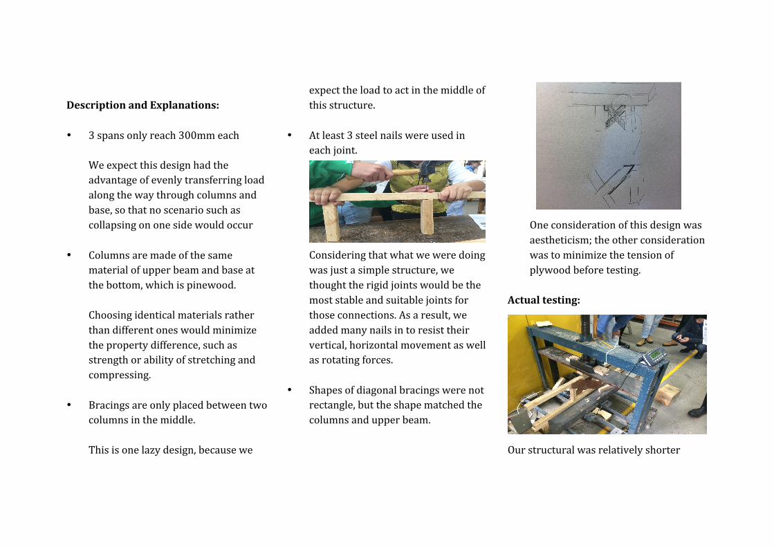
Actual testing:
Our structural was relatively shorter

compared with the structures made by other groups, so we added few timber bricks to support the edges of it. From 0kg to 100kg: Nearly nothing happens, it is easy to add loads on the structure, and only tiny noise between nails and timber was heard. From 100kg to 200kg: Adding loads were going to be harder, noise made by fiction became relatively louder. Unfortunately, the reading suddenly dropped because one nail did not be pushed in deeply enough. After resolving the problem, tiny noise of cracking could be heard when more loads were added. From 200kg to 300kg: Noise of cracking became louder, upper beam and base began to bend and undergone compression. At the same time, the diagonal bracing (plywood) started to stretch and undergone tension.
From 300kg to 400kg: Noise of cracking became very loud, beams were bending in a large scale, while plywood was stretched and seemed to reach the maximum stretching point. From 300kg to 489kg: Noise not only from pinewood, but also plywood became even louder than previous conditions. Nails seemed to be pulled out, upper beams started to fail and few cracks could be observed. Finally, the structure undergone the maximum deflection and be broken from the middle. Maximum depth: 410mm Maximum load: 489kg
Conclusions and evaluations: The structure was able to support up to 489kg of load, which is impressive, but there were also some weakness and disadvantages associated with the structure.
• Nails should be put in in a correct way. For example, nails should go to the structure vertically, not with any other angles.
• Follow the instructions to make a longer structure.

• Be more efficient with the given materials and time. During the working process, our group only used one piece of plywood, which is a kind of wasting.