Construction Verification -...
39
1 Construction Verification Using Laser Scanning technology and software Chris Palmer – Sales Engineer 28 th April 2017
Transcript of Construction Verification -...

1
Construct ion Ver i f icat ion
Using Laser Scanning technology and software
Chris Palmer – Sales Engineer 28th April 2017

2
Conten ts
What is construction verification ?
How do we measure and check construction on site today ?
How can Laser Scanning add value to the Construction process ?
Case Study 1: Bradford College
Case Study 2: Bradford ATC
Case Study 3: No.1 Spinningfields, Manchester
Case Study 4: Birmingham City University (In Progress)

3
What is Construct ion Ver i f icat ion ?
Why do we need on-site checks
What types of applications require monitoring
How do currently monitor construction
How can Laser Scanning add value

4
Why do we need onsi te checks
Main Contractor
Design Team
Client
Avoid Inaccuracies in the realisation of a design by a main contractor and monitor site progress
Provides a feedback loop for the whole project team of any changes that may be, or may have been, necessary onsite which effect construction progress.
Reduce Risk! :
– Benefit to contractor in getting quick identification of potentially costly mistakes which can cause repetition of work. Monitor and quantify sub-contractors work.
– Benefit to design team in avoiding unforeseen design ‘variations’ during construction which have a knock on effect to time and cost.
– Benefit to Client in having better cost certainty and accurate record of built asset.
Can help all parties avoid costly litigation caused by disagreements over time, cost, quantity, quality etc.

5
What requi res moni tor ing and why ?
Empty Site / Demolition
Excavations, Utilities
Foundations, Civils, Site
Frame – Concrete, Steel, Timber
Concrete Floors
Exterior Envelope, Cladding, Curtain
WallingMEP Internal Fit Out As Built Condition
• How big?• How much?
• How Deep?• Where?
• Quantity?• Record?
• Exact Position?• Deflection?
• Thickness ?• Flatness ?
• Position?• Verticality?
• Clashes ?• Record ?
• Position ?• Room Areas ?
• Complete Record !

6
How do we current ly moni tor construct ion?
Tape Measure
Total Station
Photographs
BIM 360 Field
Drone Footage

7
The Theory ……of everyth ing !
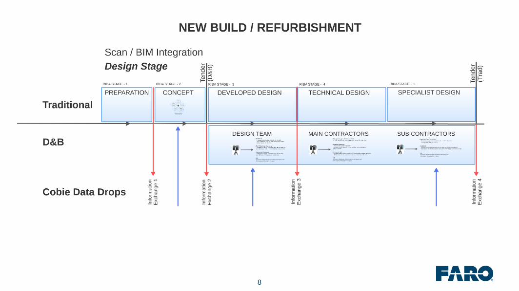
8

9
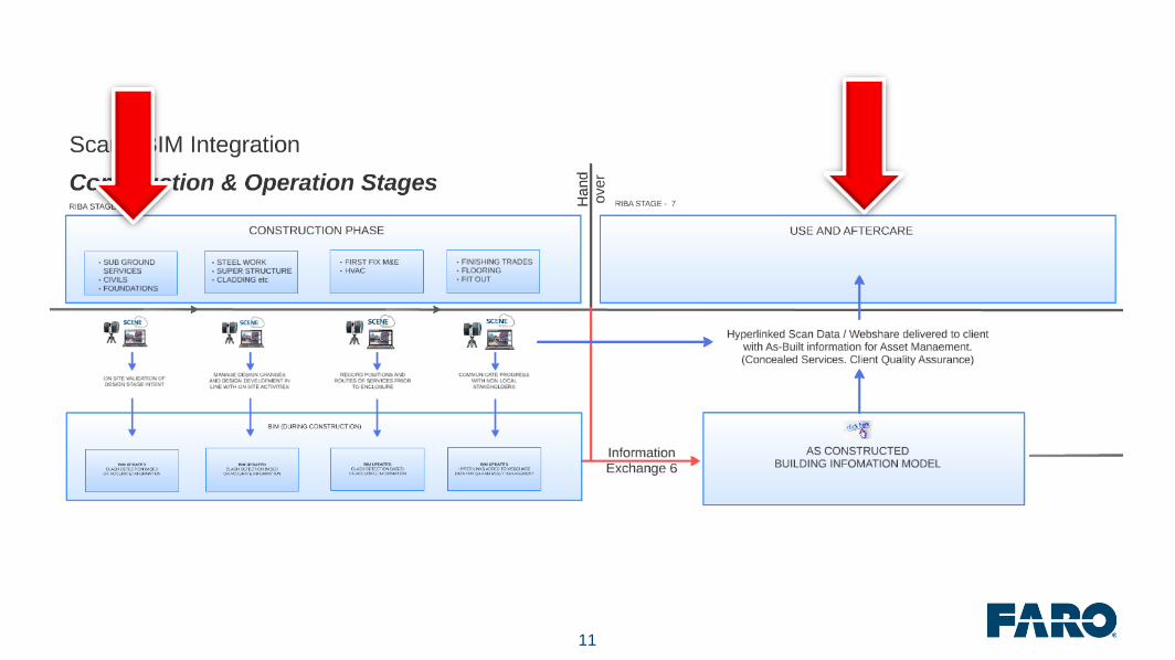
T h e T h e o r y …

10
Bradford Col lege
Scanned after Demolition and following Landscaping
11
12
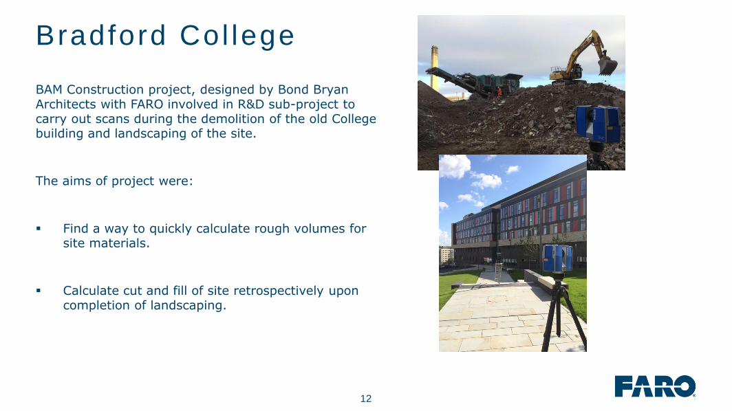
BAM Construction project, designed by Bond Bryan Architects with FARO involved in R&D sub-project to carry out scans during the demolition of the old College building and landscaping of the site.
The aims of project were:
Find a way to quickly calculate rough volumes for site materials.
Calculate cut and fill of site retrospectively upon completion of landscaping.
Bradford Col lege

13
Laser Scanning End-to End Workf low
Capture Process Create
Clean Up
Quantification
Registration
Isolate
& Extract
Civil Works
Modelling
Volume App

14

15

16
Volume Extract ion in Autodesk Civ i l 3D

17
Bradford ATC
Three Storey Steel and Concrete Frame
Scanned During Construction and after completion

18

19
▪ 4D point Cloud consists of 30 Scans during Construction. 166 After Completion.
▪ Modern methods of automated target less registration depend on scan overlap and similarity of features.
▪ Scanning overtime throws this on it’s head as everything is different and constantly changing.
▪ Registration of scans taken over time is therefore larger dependant on known co-ordinates and planes / points which can be created on surrounding geometry.
Bradford ATC

20
.RCP Export
Register Scans, apply control, define coordinate system
Externals.rcs
Import each .rcsindividually in Navisworks
or back into recap to group as an RCP file
Batch import for file size manageability /
clean up, create regions and export
Ground Floor.rcs
First Floor.rcs
Central Stairwell.rcs
Second Floor.rcs
Structural Frame (Areas A – D).rcs
Search sets don’t work on Point Clouds so manual segmentation is critical for data management
and clash result validity
Opt imis ing the Recap Fi le

21
Dur ing Construct ion Scans
22
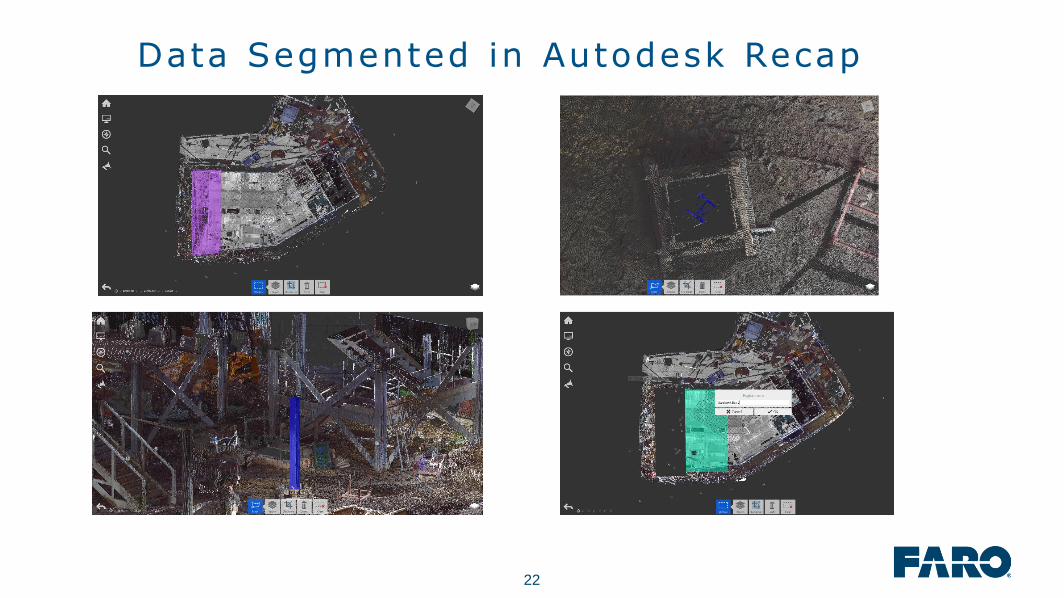
Data Segmented in Autodesk Recap

23
Extracted & Unif ied Structural Frame

24
4D Laser Scans in Recap

25
C l a s h D e t e c t i o n – D e s i g n M E P v s A s B u i l t S t e e l

26
We b s h a r e h y p e r l i n k s w i t h i n A s B u i l t B I M
27
4D Webshare Cloud Project
Project created
retrospectively, however
could be created
throughout project if
coordinate system
defined at the outset.
During construction
scans as .cpe file = 1.5gb
As Built Scans as .cpe
file = 14gb

28
No.1 Spinningf ields
Concrete Floor Flatness and Beam Deflection
Mixed Reality views
SKUR model accuracy analaysis

29

30
Scan and Model Al ignment
Scan registered to site coordinates rather than design coordinates

31
Concrete Floor F latness
Created using
the Rithm Apps
available on
the FARO App
store

32
Beam Def lect ion Analys is
Created using
the Rithm Apps
available on
the FARO App
store

33
Navisworks model in to Scan View
Created using
.NWD file and
Recap 360 Pro

34
SKUR Analys is
Cloud Based Service
Uses .pts and .e57 scan formats and .dwg
Produces layered heat map Point Cloud
Colourises .dwg based on deviation
Produces difference report with breakdown of results

35
SKUR Analys is

36
SKUR Analys is

37
Birmingham City Universi ty
In Progress…..
VR Site Progress checks ?
AR mixed Reality checks ?

38

39
Any Quest ions ?