Construction Permit for Peach Bottom Atomic Power Station ... · MicroLogix Programmable...
66
Exel ns. Exelon Nuclear Telephone 717.456.7014 Nuclear Peach Bottom Atomic PoweT Station www.exeloncoTp.coM 2848 Lay Road Delta, PA 17314-9032 November 15, 2004 Mr. Thomas Filip Pennsylvania Department of Environmental Protection 909 Elmerton Avenue Harrisburg, PA 17110-8200 Subject: Construction Permit for Peach Bottom Atomic Power Station PWS Id 7670905 Dear Mr. Filip, The purpose of this letter is to request minor changes to the Peach Bottom Atomic Power Station's Construction Permit 6704501. We are proposing to modify the permit to allow the station to modify their water treatment plant to comply with the PADEP's Long Term 1 Enhanced Surface Water Treatment Rule. Peach Bottom's domestic water system is currently in compliance with the DisinfectanVDisinfection Byproduct Rule. The work planned on the chlorination system is not required for compliance but is an enhancement to system control. Our initial application for our construction permit indicated that the currently installed Programmable Logic Controller (PLC) would be reprogrammed to allow the system to filter to waste during the initial spike in turbidity when the domestic water pumps initiate. The new system would filter to waste until the turbidity was less than 0.3 NTU. The PLC is old and it needs to be replaced. In addition, the piping configuration of the system will not allow filtering to waste duration determined by the turbidity. Therefore, a set time period will have to be used. Based on the data from historical strip charts, the time period will be between 7 and 10 minutes. The precise time will be a tunable parameter and will be adjusted as necessary. The new PLC is an Allen-Bradley MicroLogix 1000. The new controller is a direct replacement of Peach Bottom's existing PLC. The Technical Data sheet is attached to this letter. The function of the PLC does not change from the function described in the application. To replace the PLC, both of the polishing filters must be removed from service. Since both filters will be removed from service, we will request, under a separate letter, a temporary truck to supply water to the Domestic Water Storage Tank. While we have the truck, we intend to install the PLC, the turbidimeters, the turbidity recorder, the flow recorder, and the totalizer. coa
Transcript of Construction Permit for Peach Bottom Atomic Power Station ... · MicroLogix Programmable...
Exel ns.Exelon Nuclear Telephone 717.456.7014 NuclearPeach Bottom Atomic PoweT Station www.exeloncoTp.coM2848 Lay RoadDelta, PA 17314-9032
November 15, 2004
Mr. Thomas FilipPennsylvania Department of Environmental Protection909 Elmerton AvenueHarrisburg, PA 17110-8200
Subject: Construction Permit for Peach Bottom Atomic Power StationPWS Id 7670905
Dear Mr. Filip,
The purpose of this letter is to request minor changes to the Peach Bottom AtomicPower Station's Construction Permit 6704501. We are proposing to modify the permitto allow the station to modify their water treatment plant to comply with the PADEP'sLong Term 1 Enhanced Surface Water Treatment Rule.
Peach Bottom's domestic water system is currently in compliance with theDisinfectanVDisinfection Byproduct Rule. The work planned on the chlorination systemis not required for compliance but is an enhancement to system control.
Our initial application for our construction permit indicated that the currently installedProgrammable Logic Controller (PLC) would be reprogrammed to allow the system tofilter to waste during the initial spike in turbidity when the domestic water pumps initiate.The new system would filter to waste until the turbidity was less than 0.3 NTU. ThePLC is old and it needs to be replaced. In addition, the piping configuration of thesystem will not allow filtering to waste duration determined by the turbidity. Therefore, aset time period will have to be used. Based on the data from historical strip charts, thetime period will be between 7 and 10 minutes. The precise time will be a tunableparameter and will be adjusted as necessary.
The new PLC is an Allen-Bradley MicroLogix 1000. The new controller is a directreplacement of Peach Bottom's existing PLC. The Technical Data sheet is attached tothis letter. The function of the PLC does not change from the function described in theapplication. To replace the PLC, both of the polishing filters must be removed fromservice. Since both filters will be removed from service, we will request, under aseparate letter, a temporary truck to supply water to the Domestic Water Storage Tank.While we have the truck, we intend to install the PLC, the turbidimeters, the turbidityrecorder, the flow recorder, and the totalizer.
coa

The equipment, which will contact the water, will be washed with a sodium hypochloritesolution before installation. The piping will be flushed with chlorinated water andsampled for total coliform bacteria. The water samples, from the flushed samples, mustbe free of total coliform bacteria before the system can be returned to service.Disinfection of the new components will be as described in the previously approvedapplication.
Peach Bottom will request an inspection and seek the PADEP's permission to place thesystem in-service after the polishing filter work is complete. A final inspection andissuance of the operating permit would occur after the hypochlorite system work iscomplete.
If you have any questions on this amendment to our application or the project, pleasecontact Mr. Arthur Arcilla {717} 456-4185, or Ms. Barbara Payne {717} 456-3410.
Thank you for your cooperation in this matter.
Sincerely,
Joseph P. Grimes, Plant ManagerPeach Bottom Atomic Power Station
cc: USNRC Region I Document Control DeskT. J. SiglinD. J. FossD. M. Jordan
Ccn 04- 14o8 5

MicroLogixProgrammableControllersSelectionGuide
1761, 1762 1764
(:id RockwellAutomation

2 MicroLogix Programmable Controllers Selection Guide * j
MicroLogix OverviewThe MicroLogix family of programmable controllers provides 3 levels of control. Small onsize, big on performance, the MicioLogix 1000 offers control capabilities in an affordable,compact package. The MicroLogix 1200 is small enough to fit in tight spaces, but powerfulenough to accommodate a broad range of applications. Designed to grow as your needsgrow, the MicroLogix 1500 helps you achieve high-level control in a variety ofapplications.
MicroLogix 1000 Description
Based on the architecture of the market-leading SLC 500 controller family, the MicroLogix1000 brings high speed, powerful instructions and flexible communications to applicationsthat demand compact, cost-effective solutions.
The MicroLogix 1000 programmable controller is available in 10-point. 16-point or 32-pointdigital 1/O versions. Analog versions are also available with 20 digital 1/O points and 5analog I/O points.
The analog I/O circuitry for the MicroLogix 1000 units is embedded into the basecontroller, not accomplished through add-on modules. So, it provides very high-speed,cost-effective analog performance.
The MicroLogix 1000 controller utilizes RSLogix 500 programming software and shares acommon instruction set with the MicroLogix 1200, MicroLogix 1500 and SLC 500 familiesof controllers.
Publication 1761-SGOOIA-EN-P

Microtogix Programmable Controllers Selection Guide 3
Advantages* Fast processing allows for lypical throughput time of 1.5 ms for a 500-instruction
program
* Built-in EEPROM memory retains all of your ladder logic and data if the controller losespower, eliminating the need for battery back-up or separate memory module
* Multiple input and output commons allow you to use the controller for either sinking orsourcing input devices and provide isolated commons for multi-voltage outputapplications
* Peer-to-peer messaging capability allows you to network up to 32 controllers on a DH-485 network (using a 1761-NET-AIC module)
* RTU slave protocol support using DF1 Half-Duplex allows up to 254 slave nodes tocommunicate with a single master using radio modems, leased-line modems or satelliteuplinks
* RS-232 communication channel allows for simple connectivity to a personal computerfor program upload, download and monitoring
* Controllers that have 24V dc inputs include a built-in high-speed counter (6.6 kHz)
* Adjustable DC input filters allow you' to customize the input response time and noiserejection to meet your application needs
* Regulatory agency certifications for world-wide market (CE. C-Tick, UL. c-UL, includingClass 1 Division 2 Hazardous Location)
Publication 1761-SG001A-EN-P
4 MicroLogix Programmable Controllers Selection Guide
MicroLogix 1200 Description
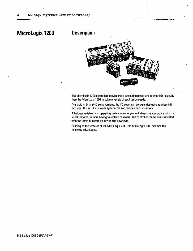
The MicroLogix 1200 controllers provide more computing power and greater I/O flexibilitythan the MicroLogix 1000 to solve a variety of application needs.
Available in 24 and 40-point versions, the I/O count can be expanded using rackless I/Omodules. This results in lower system cost and reduced parts inventory.
A field-upgradable flash operating system ensures you will always be up-to-date with thelatest features, without having to replace. hardware. The controller can be easily updatedwith the latest firmware, via a web site download.
Building on the features of the MicroLogix 1000, the MicroLogix 1200 also has thefollowing advantages.
Publication 1761-SG001A-EN-P

MicroLogix Programmable Controllers Selection Guide 5
Advantages* Large 6K memory lo solve a variety of applications
* High performance expansion I/O options (up to 6 modules depending on power budget)
* Advanced communications options including peer-to-peer and SCADA/RTU networks.DH-485, DeviceNet and EtherNet/IP via the Communications Port iChannel 0) on thecontroller
* An additional Programming/HMI Port, providing connectivity to a DF1-full Duplexcompatible device such as an operator interface or programming terminal (MicroLogix1200R only)
* Communications toggle push button that allows the controller's Channel 0 port to togglebetween user configured communications parameters and factory default settings foreasy programming or troubleshooting
* Data file download protection prevents critical user data from being ahered via programdownloads
* Two built-in analog trim potentiometers
* Optional real-time clock
* Optional memory module
* High-resolution, 1 ms timers
* 20 kHz high-speed counter, featuring 8 modes of operation
* One high-speed output that can be configured as 20 kHz PTO (Pulse Train Output) or asPWM (Pulse Width Modulated) output
* Four high-speed latching (pulse-catch) inputs
* Four event interrupt inputs (EIl)
* One, 1 ms, selectable timed interrupt (STI)
* 32-bit signed integer math
* Floating-point data file
* Built-in PID capabilities
* ASCII read/write capability
* Finger-safe terminal blocks meet global safety standards
* Removable terminal blocks on 40-point controllers allow pre-wiring
Publication 1761-SGOO1A-EN-P

6 MicroLogix Programmable Controllers Selection Guide
MicroLogix 1500 Description
The MicroLogix 1500 is a world-class programmable logic control platform with even moreadvanced features and performance than the MicroLogix 1200. Many of these featuresallow this controller to be used in applications where much larger controllers wererequired in the past.
MicroLogix 1500 architecture features an innovative two-piece design with a smallfootprint. The processor and base units slide together to form the complete controller.The processor and base are independently replaceable, allowing you to maximize yourembedded 1/O options while mn.imizing inventory stocking costs.
Bulletin 1769 Compact V/O modules expand the controller's embedded I/O offerings andprovide the additional flexibility to cover a wide range of applications. This high-performance modular and rackless I/O platform provides front accessibility for removaland insertion, lowering system cost and reducing maintenance time.
New features are provided with an enhanced user interface that uses function files toconsolidate programming parameters. This simplifies the user interface and increasescontroller performance.
The MicroLogix 1500 includes all the features of the MicroLogix 1200, plus more.
Publication 1761-SGOO1A-EN-P

MicroLogix Programmable Controllers Selection Guide 7
Advantages* Large memory to solve a variety of applications.
1764-LSP: 7K user program capacity1764-LRP: 14K user, program capacity
* Recipe (RCP) instruction saves custom lists of recipe data
* Data logging (1764-LRP only) instruction stores data records with optional lime stamp ina separate 48K byte memory area
* High performance expansion I/O options (up to 16 modules)
* Additional configurable RS-232 communications port on the 1764-LRP processor forpeer-to-peer and SCADA/RTU networks, DH-485, DeviceNet and EtherNet/IlP
* Battery (built-in and optional replacement)
* Mode switch for Run/Remote/Program
* Optional data access tool (DAT) for monitoring and changing integer and bit values
* Two high-speed outputs that can be configured as 20 kHz PTO (Pulse Train Output) or asPWM (Pulse Width Modulated) outputs
* Eight high-speed latching (pulse-cateh) inputs
* Removable terminal blocks on all Base Units and I/O modules allow pre-wiring
Publication 1761-SG001A-EN-P
8 MicroLogix Programmable Controllers Selection Guide
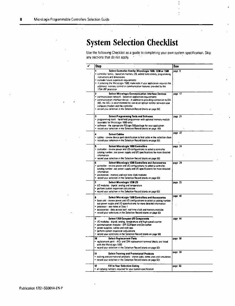
System Selection ChecklistUse the following Checklist as a guide to completing your own system specification. Skipany sections that do not apply.
StUp See1 Select Controller Family: MicroLogii 1000I12ttev 1500 page 9* controller family -based on memory, 1/0 added functionality. programming
instructions and dimensions* considel future expansion requirements* I selecting the Micrologix 1500. make note it your application requires the
additional memory, control or communicalion ieatures provided by the1764-LRP processor
2 Select Micrologix Communication Interface Devices page 17tCommunication network -based on application requirements
*communication interface device - in addition to providing connection to OH-485. the AIC4 is recommended for use as an optical isolator between yourcomptner/modem and the controller
*record your selection in the Selection Record stants on page 60)
3 Select Programming Tools and Software page 21* programming tools- hand-held programmer with optional memory module
lavailable for MICroLogix 1000 only)
* software - the appropriate RSLogix 50(package for your application* record your selection in the Selection Record Istans on page 60i
4 Select Cables page 22* cables - review device port identification to find cable in the selection chan* record your selection in the Selecition Record (starts on page 601
5 Select MicroLogix 1000 Controllers page 24* controller - review power and i/D configurations to select a controller
catalog number, see power supply and 1/0 specifications for more detailedinformation
*record your selection in the Selection Record Istarts otn page 60)
6 Select Micrologix 1200 Controllers and Accessories page 29* controller - review power and 1/0 configurations to select a controller
catalog number. see power supply and 110 specifications for more detailedinformation
* accessories - memory and real-time clock modules* record your selection in the Selectiort Record (stans on page 60)
7 Select Micrologix 1200 VO page 33* 1/0 modules - dignal. analog and temperature* perfomm system expansion calculations* record your selection in the Selection Record (starts on page 60)
R Select MicroLogix 1500 Controllers and Accessories page 40* base unit - review power and 1/0 configurations to select a catalog number.
see power supply and i/D specifications for more detailed information* processor - see notes at Step 1* accessories - data access tool, real-time clock and memory modules* record your selections in the Selection Record (stans on page 601
9 Select 1769 Compact 1/0 Components page 44* i/0 modules -digital, analog, temperature and high-speed counter* communication modules -DPI SCANpon and DeviceNel* power supplies, cables and end caps* perform system expansion calculations* record your selections in the Selection Record (stans on page 60)
10 Select Replacement Parts page 58* replacement parts -AIC4 and DNI replacement terminal blocks are listed
with the MicroLogix 1000)* record your selection in the Selection Record (stans on page 601
11 Select Training and Promotional Products page 59* training and promotional products - sarter paks. demo urnts and simulators* record your selection in the Selection Record (starts on page 60)
12 Fill in Your Selection Listing page 60* all catalog numbers required for your system specification
Publication 1761-SGOOIA-EN-P
MicroLogix Programmable Controllers Selection Guide 9
Step 1 - Select
* controller family - based on memory 1/0,added functionality, programminginstructions and dimensions
• consider future expansion requirements
* if selecting the MicroLogix 1500, makenote if your application requires theadditional memory control orcommunication features provided by the1764-1iP processor
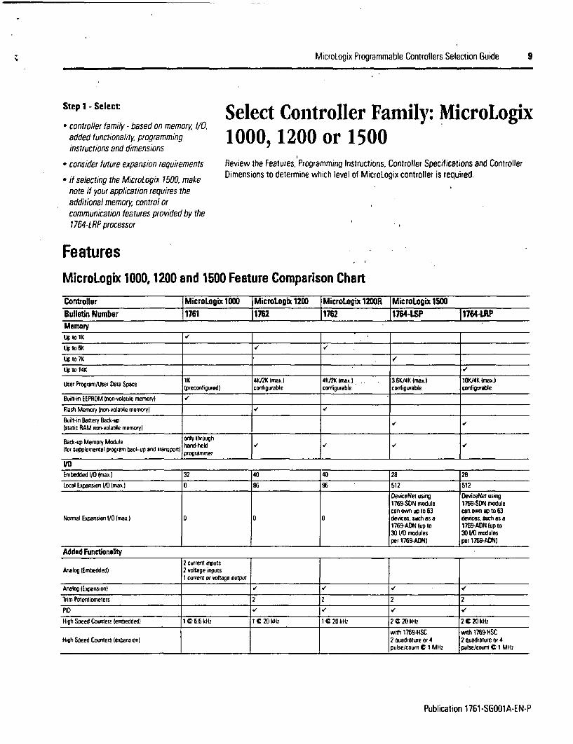
Select Controller Family: MicroLogix1000, 1200 or 1500Review the Features, Programming Instructions, Controller Specifications and ControllerDimensions to determine which level of MicroLogix controller is required.
FeaturesMicroLogix 1000, 1200 and 1500 Feature Comparison Chart
Controller I MicroLogix 1000 I MicroLogix 1200 | MicroLogix 1200R I MicroLogix 1500Bulletin Number 1761 1762 1762 1764-LSP 1764-LRPMemoryUp to 1K .
Lptot 6 K
LiptoTK .o'
up to 14K
tK 4KI2K Imal.I 4K/2K Imax I . . 3.6K/4K Imax.l 1OK/4K Imax.lUser Program/lser Data Space Ipreconfigured) contfgurabie conigurable configurable configurable
Built-in EEPROM Inon-volatile memory) .
Flash Memory inon-volatile memory) V /
Built-in Battery Back-up(static RAM non-volaide memory)
Back-up Memory Module only throughtor supplemental program back-up and transport) proramnmer
1/0Embedded I/0 (maxl. 32 40 40 28 28
Local Expansion It0 Imax)j 0 96 512 512
DeviceNet using DeviceNet using1769-SON module 1769-SON modulecan own up to 63 can own up to 63
Normal Expansion 1/0 (max.) 0 0 0 devices. such as a devices. such as a1769-ADN lup to 1769-ADN (up to30 i/O modules 30 1/0 modulesper 1769-ADN) per 1769-ADNj
Added Functionality2 Current inputs
Analog iEmbedded) 2 voltage inputs1 current or voltage output
Analog (Expansion)
Trim Potentiometers 2 2 2 2
PID
High Speed Counters lembedded) 1 t 6.6 kHz I C 20 kHz 1 t 20 kHz 2 ¢ 20 kHz 2020kHz
with 1769-HSC with 1769-HSCHigh Speed Counters (expansion] 2 quadrature or 4 2 quadrature or 4
pulse/count C 1 MHz pulse/count a 1 MHz
Publication 1761-SGOO1A-EN-P
10 MicroLogix Programmable Controllers Selection Guide
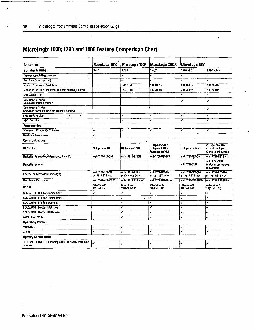
MicroLogix 1000; 1200 and 1500 Feature Comparison Chart
Contoiller MicroLogix 1000 Micrololsx 1209 MicroLogix 1200R MicroLogix 1500Bulletin Number 1761 1762 1762 1764-LSP 11764-LRPTherMocouple/RlTD lexpansion) . . /
Real Time Clock loptional) _
Motion Pulse Width Modulated 1 020 kHz 1 ) 20 k; 2 C 20 kHz 2 0 20 kHz
Motion Pulse Train Outputs tor use with stepper or servos 1 C 20 kHz 1 0 20 kH; 2 0 20 kHz 2 C 20 kHz
Data Access lool I 1
Data Logging/Recipelusing user program memory)Data Logging/Recipe(using addrtional 48K byte non-program memory)Floating Point Math V * V
ASCII Data File
Programming
Windows- RSLogix WO Software ( | _ | _
Hand-Held Programmer
Communicasions111 8-pin mini DIN 1l S-pin mini DIN
RS-232 Pons (1)8-pin mini DIN It) 8-pin nini DIN 111 8-pin mini DIN III 8-pin mini DIN (1) isolated 9-pinPNogramming/HMI D-shell ctnfigurable
DeviceNet Peer-to-Peer Messaging. Slave 1/0 with 1761-NE1-ONI with 1761-NET-DNI with 1761-NEI-DNI with 1761-NET-DNI with 1761-NEI-DNI
with 1769-SDNDeviceNet Scanner with 1769-SDN (includes peer-to-peer
messaging)with 1761-NE7-ENI with 1761-NE1-ENI with 1761-NE1-ENI with 1761-NE1-ENI with 1761-NET-ENI
EtherNet21P Peer-to-Peer Messaging or 1761-NE1-ENIW or 1761-NET-ENIW or 1761-NET-ENIW or 1761-NET-ENIW or 1761-NET-ENIW
Web Server Capabilities with 1761-NET-ENIW with 1761-NET-ENIW with 1761-NE1-ENIW with 1761-NE1-ENIW with 1761-NET-ENIW
network with network with network with network with network withDH-485 1761-NET-AIC 1761 -NET-AIC 1761-NEl-AIC 1761-NET-AIC 1761-NET-AIC
SCADA RTU DF1 Hali-Duplex Slave V II
SCADA RFTU - DF1 Hati-Duplex Master I *
SCADA RTU - DF1 Radio Modem VI/ V
SCADA RTU - Modbus RTU Slave 1 1
SCADA RTU -Modbus RTU Master
ASOI- Read/Wnte I I
Operating Power120/240Vac24V dc _
Agency CertificatonsCE. C-Tick. UIL and C-UI lincluding Class I. Division 2 Hazardous | |Location)
Publication 17B1-SGOO1A-EN-P

MicroLogix Programmable Controllers Selection Guide 11
Programming MicroLogix controllers have the range ol functionality necessary to address diverseapplications. The controllers use the following types of instructions:
Instructions* Basic Instructions (i.e., Examine if On, Examine if Off)
* Data Comparison lhstructions li.e., Equal, Greater than or Equal, Less than or Equal)
* Data Manipulation Instructions (i.e.. Copy, Move)
* Math Instructions (i.e.. Add, Subtract, Multiply)
* Program Flow Control Instructions (i.e., Jump, Subroutine)
* Application Specific Instructions (i.e., Programmable Limit Switch, Sequencer)
* High-Speed Counter Instruction
* Communication Instruction (including ASCII for Microtogix 1200 and 1500 onlyl
* High-Speed PTO (Pulse Train Output) and PWM (Pulse Width Modulated) Instructions(Micrologix 1200 and 1500 only)
* Recipe Instruction (MicroLogix 1500 only)
* Data Logging Instruction (Microtogix 1500 1764-LRPprocessor only)
ControllerSpecificationsController General Specifications
Micrologix 1000 MicroLogix 1200 MicroLogix 1500Specification (Bulletin 1761) (Bulletin 1762) (Bulletin 17643
1764-ESP proessor: 7K user memory
Memory Size and Iype 1K EEPROM lapproximately 737 6K flash memory Itotal user program plus data)instruction words. 437 data words) AK user program. 2K uset data 1764-tRP pxocessor: 14K user memoryItotal user program plus datal
512 internal bits. 4O timers.Oata Elements 32 counterns 16 control ies, configurable. user defined file structure 2K configurable. user defined file structure. 4K
105 irmeger files. 33 diagnostic status max data size max. data size
Thioughput 1.5 ms ( for a typical 500-instruction program) * 2 ms (for a typical 1 K word user programl * 1 ms (for a typical 1 K word user program) *
* A rypical piogiam conrrairs 30 iontacts. 125 coils. 7 timers, 3 couniers and 5 compaiison irixrtrlions.* A rytocal usei pogram conrains . rIrrner. couner. mat and Ik insi riociuns
Publication 1761-SGOO1A-EN-P
12 MicroLogix Programmable Controllers Selection Guide
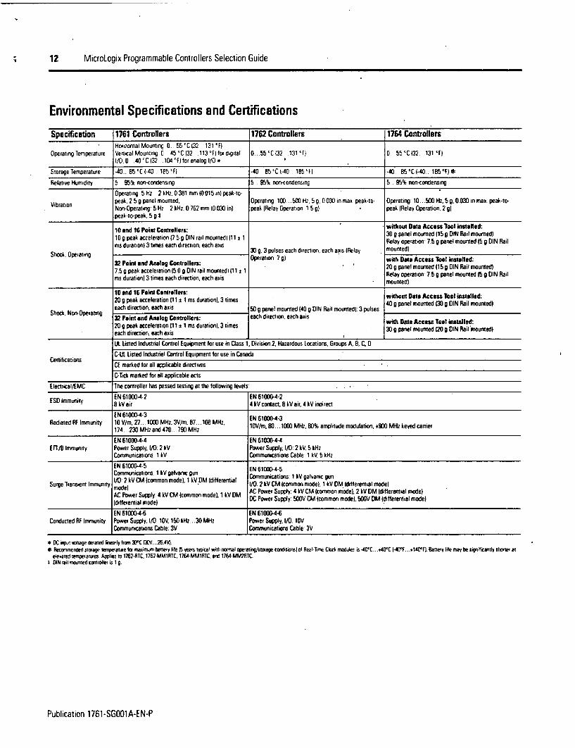
Environmental Specifications and Certifications
Specification 1761 Controllers 1762 Controllers 1764 ControllersHorizontal Mounting 0 55 'C 132 131 'F)
Operating m emperature Vertical Mounting 0 45 'C 132 .113 'F) for digital 0 .55 'C (32 .131 'F) 0 55 'C (32 131 'Fl1/0.0 .40 'C i32 104 F) tor analog I/O *
Storagelemperature .40_ 85'C(-40_.185'Fl -40 85'C6-40 185'FI *40 . 85'CI-40.. 185'f)*
Relative Humidity 5 .95% non-condensing 5 95% non-condensing 5_. 95% non-condensing
Operating 5 Hz 2 kHz, 0 381 mm 10 015 in) peak-lo-
Vibration peak. 2 59 panel mounted. Operating 100 . 500 H., 5 G. 0 030 in max peak-to Operating 10... 500 Hz. 5 9. 0 030 in max. peak-to-Non-Operating 5 Hz .2 kHz. 0 762 mm (0.030 in) peak (Relay Operation 1 5 g) peak (Relay Operation 20g)peat-to-peak, 5 g I
10 and 16 Point Centrellern: .. without Data Access Tool installed:10 g peak acceleration 17 5 g DIN rail mounted) 11 i 30 o panel mounted 150 DIN Ral mouned)ms duration) 3 times each direction. each axis Relay operation 7. g panel mounted 15 G DIN Rail
Shock. Operating 30 . 3 pulses each direcion, each sxis (Relay . mountedl32 Point and Analog Controllers: Operation 7 a , mith Data Acess3 ll installed:7.5 0 peak acceleration 15.0 g DIN rail mounted) (11 ± 1 . 209 panel mounted 15 9 DIN Rail mouned)ms duration) 3 times each direction, each axis Relay operation 7.5 g panel mounted 15g DIN Rail
. mounted)10 end 16 Point Controllers: without Date AccessTool installed:20 9 peak acceleration (11 ± 1 ms duration), 3 times 40 9 pane) mounted e 30g DIN Rail mounted)
Shock Non-Opeling each direction, each axis 50 g panel mounted (40 G DIN Rail mounted). 3 pulses 40_Gpanelmounted_130_GDINRail________32 Point nd Analog Controllers: each direction, each axis Data Access Toot installed20 g peak acceleration (1 I11 ms durationl, 3 times 30. panel mounted 120 DIN Rail mounted)
UL Listed Industrial Control Equipment for use in Class 1, Division 2. Hazardous locations, Groups A, B, C. D
C-UL Listed Industrial Control Equipment for use in CanadaCertifications
CE marked for all awlicable directives
C-Tick marked for all applicable acts
Electrncal/EMC The controller has passed testing at the following levels
EN 61000-4-2 EN 61000-4-2SD immunity 8 kV air 4 kV contact. 8 kV air. 4 kV indirect
EN 61000-4-3Radiated RF Immunity 10 V/m, 27.. 1000 MHz. 3V/m, 87. .108 MHz, ENV/m. 80. .. i0- MHz. 804 amplitude modulation, 9D- MHz skeyed carier
174... .23 MHz and 470.. 790 MHz 1Vt.8..1 ~.8%apiuemdlto,.0 ~ ee are
EN 61000-4-4 EN 61000-4-4EFli/B Immunity Power Supply. 1/0 2 kV Power Supply, 1/0: 2 tV 5 kHz
Communications: 1 kV Communications Cable: 1 kV, 5 kHz
EN 61 000-4-5 EN 61000-4-5Communications: 1 kV galvanic gunComncios kVglacgu
Surge Transiem Immunity 1/0 2 tV CM (common mode. 1 V tM (differentil CommuDnicat ions 1 tV ga lvanc gunmode) AC0 2oe upy kV CM (common mode). 1 kV DM ( differ ential modelAC Power Supply 4 kV CM (common model) 1 kV DM AC Power Supply: 4 kV CM (common mode). 2 OV DM Idifierential mode)(differential model) oe upy OVC cmo md) OVO dfeeta oe
EN 61000-4-6 EN 61000-4-6Conducted RF Immunity Power Suppy. 1/0: 10V. 150 &Hz. .30 MHz Power Supply, 1/0: 10V
Communications Cable: 3V Communications Cable: 3V
* DC irs dsage i*ated lirvearly srom 3D C WV ...26 *.* Recomieried storage temperatre la uiaoimum banery life (5 tears typical mith nonnal opearing/storage coridironsl os RealTime Clocb moduler is *40'C ..40'C -40'Pf . .+40'fl baneri lite may be significantly shorter or
elequred rempeLarives. Applies to 1762-R7C. 17E2-MM1R1C. 1764-MMtRTC. and 1764-MM22RC.t DN Ioil mounted conrioller is I g.
Publication 1761-SG001A-EN-P
MicroLogix Programmable Controllers Selection Guide 13
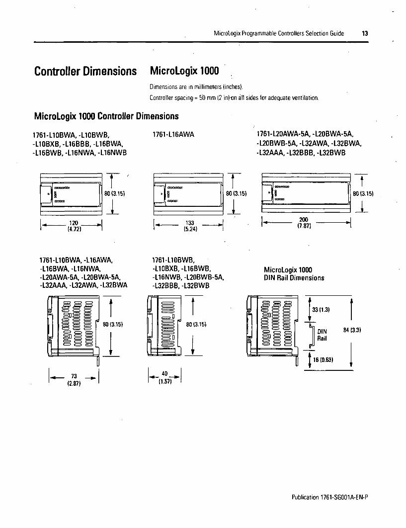
Controller Dimensions MicroLogix 1000Dimensions are in millimeters (inches).
Controller spacing = 50 mm (2 in)von all sides for adequate ventilation.
MicroLogix 1000 Controller Dimensions
1761-LlOBWA, -L1OBWB,-LlOBXB, -L16BBB, -L16BWA,-L16BWB, -L16NWA, -L16NWB
17611-L16AWA 1761-L20AWA-5A, -L20BWA-5A,-L20BWB-5A, -1L32AWA, -L32BWA,-1L32AAA, -L32BBB, -L32BWB
880 (3.15) 8013.15)
-4
l
.I . 80(3.15)
II - (4.72)
1331 (5.24) 1 1' (7.87) -
1761 -Ll OBWA, -L16AWA,-L16BWA, -L16NWA,-L20AWA-5A, -L20BWA-5A,-L32AAA, -L32AWA, -L32BWA
1761-LlOBWB,-LlOBXB, -L16BWB,-L16NWB, -L20BWB-5A,-L32BBB, -L32BWB
MicroLogix 1000DIN Rail Dimensions
8013.15)
4,F
JI
,! I
80 13.15)0
r
88 3= C
csn, CE cS
00= = C= 311) _- C=
C=,[ tl C
3(1.3)
DIN 84 (3Rail
6 610.63)
.3)
7312.87)
__1 40 11 (1.57)
Publication 1761-SG001A-EN-P

V 14 MicroLogix Programmable Controllers Selection Guide
MicroLogix 1200Dimensions are in millimeters (inches).
Conlroller spacing = 50 mm (2 in) on all sides for adequate ventilation.
MicroLogix 1200 Controller Dimension Drawing
1762-L24AWA, 1762-L24BWA, 1762-L24BXB 1762-L40AWA, 1762-L40BWA, 1762-L40BXB1762-L24AWAR, 1762-L24BWAR, 1762-L24BXBR 1762-L24AWAR. 1762-L24BWAR, 1762-U4BXBR
MicroLogix 1200 Controller Dimensions
1762-L24AWA 1762-L24BWA 1762-L24BXB 1762-L4OAWA 1762-L40BWA 1762-L40BXBDimension 1762-L24AWAR 1762-L24BWAR 1762-L24BXBR 1762-L4OAWAR 1762-L40BWAR 1762-L40BXBRA 90 mm (3 5 in) 93 mm (3.5 in)
B 10 mm 14.33 in) 160 mm 1(630 in)
c 87 mm (3.43 in) 87 mm (3.43 in)
1762 Expansion l/0 Dimensions
A
Dimension Expansion 10 ModuleA 90 mm 13.5 in)
40 mm 11.57 in)
,C 87 mm 13 43 in
Publication 1761-SGOO1A-EN-P

MicroLogix Programmable Controllers Selection Guide 15
MicroLogix 1200 System Mounting Dimensions
Dimensions are in millimeters (inches).
Hole spacing lolerance: ±0A4 mm t0.0i6 in)
For more than 2 modules: lnumber of modules - 1) x 40 mm 11.58 in) I
145 40410.571 (I 59
A = 95.86 mm 13.774 in)1762-L24AWA, 1762-L24BWA, 1762-L24BXB1762-L24AWAR, 1762-L24BWAR, 1762-L24BXBR
B = 145.8 mm 15.739 in)1762-L40AWA, 1762-L40BWA, 1762-L40BXB1762-L40AWAR, 1762-L40BWAR, 1762-L40BXBR
Ii100 90
(3.941 (3.54)
L r3MicroLogix I ,
1200 Ze t
U".)
L r 40 VB (1.591 '
MicroLogix 1500Dimensions are in millimeters (inches).Hole spacing tolerance: ±0.04 mm (0.016 in)
Controller spacing = 50 mm (2 in) on all sides for adequate ventilation:
Compact 1/0 with MicroLogix 1500 Base Unit and Processor
168 mm 5mm,Mounting Hole (6.62 in) (1.38 in)
Dimension 147 mm 35m L(5.79 in) 1.38 in)
_ ... ....;;7 rS
Center Line t _:E cm
13.5 mm 14.7 mmcontroller depth = 87 mm (3.43 in) (0.53 in) (0.58 in)
Publication 1761-SGOO1A-EN-P

16 MicroLogix Programmable Controllers Selection Guide
Expansion Bank with Power Supply, Expansion Cable and End Cap
Mounting HoleDimension
-35 mm11.38,in)
35m1.38 in)
70 mm(2.76 in)
35m 35mm(1.38in 11.38 in)
M M
(1.38 in)
mm11.38 in)
l _
28.5 mm-1.12 in)
35mm-
L4
IDIN Rail
Center Line
E .
EEE
11 _ _ _ _3 I _ _fI 1 J13A
G
Uif
E
_ 1 .
7
Z,
E
(2
r= - 11-1 I" L-r - + M
,14.7mm(0.58 in)
Eff, - I
controller depth = 87 mm (3.43 in)Expansion Cable connector and End Cap have identical dimensions.
Spacing for Single-Wide and One and One-Half-Wide ModulesPanel Mounting Using the Dimensional Template:
Spacing for single-wide modules 35 mm (1.378 in)Spacing for one-and-a half-wide modules 52.5 mm 12.067 in)
Spacing from controller to first I/O mounting hole 35 mm (1.378 in)* 0 + 0 + *0 0 0
0
U,
0
.. A0 40 0 400 00 0
Note: Overall hole spacing tolerance: ±0.4 mm (0.016 in)
Locate holes every 17.5 mm (0.689 in) to allow for a mix of single-wide (e.g. 1769-1016) and one-and-one-half-widemodules (e.g. 1769-OA16).
Publication 1761-SGOO1A-EN-P

MicroLogix Programmable Controllers Selection Guide 17
Step 2 - Select:
* communication network - based onapplication requirements
* communication interface device - inaddition to providing connection to DH-485. the AIC4 is recommended for useas an optical isolator between yourcomputer/modem and the controller
* record your selection in the SelectionRecord (starts on page 60/
CommunicationNetworks
Select MicroLogix CommunicationInterface Devices
MicroLogix controllers allow you to choose the network that best meets your needs.
* Enhanced Channel 0 RS-232 port Includes 24V dc power for network interface devices)
* 300; 600; 1200; 4800; 9600; 19.2K and 38.4K baud rates
* RTS/CTS hardware handshake signals
* Connection to DH-485, DeviceNetand Ethernet networks through the 1761-NET-AIC,1761-NET-DNI and 1761-NET-ENI interface modules, respectively (Micro!ogix 1500: alsoconnects to DeviceNet, via the 1769-SDN DeviceNet Scanner Module)
* Connection to modems for remote communications
* ASCII messaging provides dial-out capability (Micro!ogix 1200 and 1500 controllers only)
* IF1 Half-Duplex Slave
* DFI Full-Duplex Master (Microtogix 1200 and 1500 controllers only)
* Modbus RTU Master/Slave through the 1761-NET-AIC module (Micro!ogix 1200 and1500 controllers only)
MicroLogix Network Options
f your application requires: Usa this network.* Connection to dial-up modems for remote program maintenance or data collection Fo Full-Duplex* Connection to leased-line or radio modems for use in SCADA systems o1 Half-Duplex Slave* Remote Terminal Unit IRTLu) functionsF 1 a controller Dlyv* Program upload. download and monitoringF1 Radio Modem (M'croiogis 1200 and 1500 controllers onvJ
* Plant-wide and cell-level data sharing with program maintenance* Data sharing between 32 controllers DH-485 via the 1761-NET-AIC Advanced Interlace Convener* Peer-to-peer communication 14-U IC Advanced Interface Convene* Program upload. download and monitoring or t?47-ulC usa to DH-485 Inerlace Convener* Compatibility with multiple Allen-Bradley HMI devices
* Data sharing between 64 devices* Better diagnostics for improved data collection and faut detection* Less wiring and reduced stan-up time than traditional, hard-wired systems DeviceNet via the 1761-NET-DNI DeviceNet Interlace* Program upload, download and monitoring (or 1769-SN DeviceNet ScaN er Module for the MicroLogix t500)* Peer-to-peer communication* Connection Dl low-level multi-vendor devices directly to plam floor controllers /when using the
1769-SON)
* Program upload, download and monitoring* Peer-to-peer communication EtierNet/IP via the 176t-NET-ENI Etiemet Interlace* E-mail communication* 10/10OBase-1 pon with embedded LEDS or 1761-NEI-ENIW Web-Enabled Ethernet Interlace* Web server capabdity via the 1761-NEI-ENIW
* Connection to third pany devices for remote data collection in a SCADA system (ie. Modbus ATL Slave (Mi.rologx 1200and 1500controllers only)lelephone modems, radio modems, leased lines. etc) Modbus RTU Master (Mcrlopol 1200and 1500controllers only)
* Remote lerminal Unit ]RAUl lunctions
Publication 1761-SGOO1A-EN-P

is MicroLogix Programmable Controllers Selection Guide
MicroLogix Network The network interface devices can be mounted on a panel or DIN rail. See NetworkInterface Devices Communication Port Identification on page 22 for device drawings.
Interface DevicesAIC+ Advanced Interface Converter(1761-NET-AIC)The AIC+ is an isolated, RS-232 to RS-485 electrical signal converter for supporting serial,half-duplex, multi-drop protocols; such as:
* DH-485
* DF1 Half-Duplex Master/Slave
* Modbus RTU (a single master can cQmmunicate with a maximum of 247 slave devices)MicroLogix 1200 and 1500 controllers only
Since RS-232 ports can only be connected point-to-point between two devices, an AIC+ (orsimilar device) is required whenever a MicroLogix controller is configured for one of theseprotocols and needs to communicate with more than one other device at a time. The AIC+also provides electrical isolation between each' of its three ports for a more stablenetwork and protection for connected devices.
Any MicroLogix controller can connect to either of the two RS-232 ports on the AIC+.When Channel 0 on a MicroLogix controller is connected to Port 2 (RS-232 8-pin mini-DIN)of the AIC+, the AIC+ can draw its power from the MicroLogix controller. In all othercases, the AIC+ must be powered from'an external, 24V dc power supply. The AIC+ canalso be used as an RS-232 to RS-485 converter and port isolator for any other Allen-Bradley controller or terminal with an RS-232 port.
Since the AIC+ is not a protocol converter, all devices connected to a single AIC+ (or anetwork of AIC+s) must be configured for the same protocol.
DH-485IRS-485 Network Specifications
Specification 1761-NET-AICMaximum Number of Nodes 32 per muti-drop networkMaximum Length 1219 m 14,000 fi) per mufti-drp network
Publication 1761-SGOO1A-EN-P

MicroLogix Programmable Controllers Selection Guide 19
DNI DeviceNet Interface (1761-NET-DNI)DNI capabilities
* Peer-lo-peer messaging between Allen-Bradley controllers and other devices using theDF1 Full-Duplex protocol
* Programming and on-line monitoring over the DeviceNel network
* With a DNI connected lo a modem, you can dial in to any other DNI-conirollercombination on DeviceNet
* Other DeviceNet products can send explicit IGet or Set) messages with the DNI at any time
* The controller can initiate an explicit message to a UCMM (Unconnected MessageManager) compatible device on DeviceNet
DeviceNet Specifications
Specification 1761-NET-DNIMaximum Number of Nodes 04
Maximum Length 0m Q 125K baud or 100 m C 500K baud
DeviceNet Agency Centication . OOVA conformance 2.0-A12
ENI Ethernet Interface (1761-NET-ENI) and ENIWEthernet Interface with Web Server Capabilities(1761-NET-ENIW)The ENI provides EtherNet/lP connectivity for all MicroLogix controllers and other DF1Full-Duplex devices. The ENI allows you to easily connect a MicroLogix controller to a newor existing Ethernet network to updale/download programs, communicate betweencontrollers and generate e-mail messages via SMTP (simple mail transport protocol).
The ENIW adds web server capabilities, enabling the display of 4 standard data webpages with user-configurable data descriptions and 10 user-configurable web page linkson the ENIW home page.
Ethernet SpecificationsSpecificaton 1761-NET-ENICommunication Rate 10/100 MHz (Series Cl. 10 MHz (Series A and B)Connector lO0Base-4 ISeries Cl 1OBase-1 ISeries A and B)
Publication 1761-SGOO1A-EN-P

20 MicroLogix Programmable Controllers Selection Guide
AIC+, DNI and ENI/ENIW SpecificationsNetwork Modules Specifications
Specifications 1761-NET-AIC 1761-NET-DNI 1761-NET-ENI, 1761-NET-ENIWPower Supply DC Voltage Range * 20 4 28 BV dc 11. .25V dc 20 4. .26 4V dc
Cunent Draw ImA) at 24V dc 120 mA 200 mA 100 mA
Inrush Current. Max 200 mA C 24V 400 mA C 24V 200 mA C 24V
Isolation Voltage 500V dc for one minute 500V dc for 1 minute 710V dc for one minute
Operating lemperature 0 . 60 'C 132... 140 'F)
Storage lemperature -40.. 85 'Cl-40-D 18-F)
Relative Humidity 5 95% non-condensingoperating 5. .2000 Hz. 2.5 g. 0.015 in. peak-to-
operating 10 500 Hz, 5 0 g. 0 030 in peak-to- peak, 1 hour each axis operating 10 . 500 Hz. 5.D G. 0.030 in peak-to-V nnpeakn 2 hour each axis non-operating 5 ..2000 Hz. 5 0W. 0 030 in peak-to- peak. 2 hour each axis
peak. 1 hour each axisShock. Operating 30 g, s3 times each axis 30 g. ±3 times each axis 30 g. 3 times each axis
Shock. Non-Operating 50 g. s3 times each axis 50 g. 3 times each axis 35 g WOIN rail mournt) 50 g Ipanel mountl ±3 timeseach axis
UL Listed Industrial Control Equipment for use in Class 1, Division 2. Hazardous Locations, Groups A, B. C. 0
C-UL Listed Industrial Control Equipment for use in CanadaCertifications
CE marked for all applicable directivesC-Tick marked for applicable acts
N When the device is connecrei to a Miciritgix contriroe. power is provided by the Micstogix coitrollers communication port.
AIC+, DNI and ENI/ENIW DimensionsNetwork Interface Devices Dimensions
107mm 6.6mm14.20 in) (0.26 in)
AIC+ only
71.4 mm(2.81 in) AIC4 onlyAllow 15 mm 10.6 in) 1or
DIN rail latch movementduring installation and removal.
Publication 1761-SG001A-EN-P

MicroLogix Programmable Controllers Selection Guide 21
Step 3 - Select
* programming tools - hand-heldprogrammer with optional memory module(available for Micro!ogix 1000 only)
* software - the appropriate RS!ogix 500package for your application
* record your selection in the SelectionRecord (starts on page 60)
Select Programming Toolsand Software
Hand-HeldProgrammer(MicroLogix 1000 only)
some's an�v19
The 1761-HHP-830 allows you to create, edit. monitor and troubleshoot Instruction Lisi(Boolean) programs for your MicroLogix 1000 controller. This device also allows you tostore programs and to transfer programs through the use of an optional removablememory module.
There are two memory modules:
* 1761-HHM-K08 - 8K. stores 1 program
* 1761-HHM-K64 - 64K, stores 8 programs
The RSLogix 500 ladder logic programming package helps you maximize performance.save project development time and improve productivity. This product has been developedto operate on Windows' operating systems. RSLogix 500 can be used for programmingboth the SLC 500 and MicroLogix controller families.
RSLogix 500 Selection Chart
Cat No. Descripion9324-RL010ENE RSLogix 500 Starter Edition Programming Software for MicroLogro9324RW10ENEcontroller families. (CD-ROM)
9324-RL0300ENE RSLogix 50o Standard Edition Programming Software tor SLC Scx andMicoLogix controller families- JCo-ROM)
RSLogix 500 Professional Edition CD-ROM also includes RSLogix Emulate9324.RLOONXENE C,500 RSNetworx for DeviceNet and RSNetworx for ControlNet.
ProgrammingSoftware
TIP I Download a Free Version of RSLogix 500 Starter software
Now you can download a special version of RSLogix 500 Starter Software and RSLinx Lile software to uploadand download to MicroLogix 1000 10-point controllers This version of RSLogix 500 Starter software is fully-iunctional when used with RSLinx Lae software and MicroLogix 10-point controllers. Additionally. you can usethis software to demonstrate programming capabilities using our MicroLogix 1000 16- and 32-point controllersIdemo only).Go to http:/Avww ab.com/micrologiu/ for details
Publication 1761-SGOO1A-EN-P

22 MicroLogix Programmable Controllers Selection Guide
Step 4 - Select:
* cables - review device port identificationto find cable in the selection chart
* record your selection in the SelectionRecord (starts on page 60J
Select CablesCables come in several lengths and connector styles to provide connectivity betweenMicroLogix controllers and other devices. MicroLogix 1200 controllers require Series Cversions of all 1761 cables.
Network CableSelectionController and PC Port Identification
Device Communication Port Description * Connector TypeMicroLogix 1000 Communications Pori IChannel 0) with 24V dc power for communication device B-pmn Mini DIN
MicroLogix 1200 Communications Port IChannel 01 with 24V dc power for communication device 8-pin Mini DIN
Communications Pon IChannel 01 with 24V dc power for communication device 8-pin Mini DINProgrammingflMI Port Ino 24V dc power) B-pin Mini DIN
MicroLogip 1500 BaWe unit Communications Pon IChannel 0) with 24V dc power for communication device B-pin Mini DIN
MicroLogix 1500 with Base Llnit Communications Pon (Channel 0) with 24V dc power for communication device B-pin Mini DIN1764-LRP Processor Processor Communications Pon (Charyel 1) B-pin 0 Shell (isolated)
Personal Computer Personal Computer Communications Port' pin D Shell
Network Interface Devices Communication Port Identification
AIC+ . ONI ENVENIW
DH-485 RS-232
e 0 B-Pin Mini DIN Ethernet iPi jCJ E-Pin Mini DIN0 0'
RS-232 A CO9-Pin D Shell RS-2320
f-Pin Mini DIN
The AIC+ is recommended for isolation purposes when the controller and an operator interface deviceare not using the same power supply. 0
Network Cable Selection Chart
Connectors Length Cat No. Connectors Lengt Cat No.8pin Mini DIN to 8pun Mini DIN 0.5 m (1.5 ht) 1761-CBL-AMoo 8-pin Mini DIN to 9-pun D Shell 0.5 m 12)5 nJ 1761-CBL-AP0O
B-pin Mini DIN lo 8-pn Mini DIN 2 m 16.5 It) 1761 -CBL-HMO2 B-pin Mini DIN to 9-pin D Shell 2 m 16.5 It) 1761.CBL-PMO2
8-pin Mini DIN to &-pn Mini DIN 5 m (16 ht) 2711-CBL-HMOS B-pin Mini DIN to 9-pin D Shell 5 m 116 It) 2711-CBL-PMO5
8-pin Mini DIN to 8pin Mini DIN 10 m 132 ht) 2711-CBL-HM10 8-pin Mini DIN to 9-pin D Shell 10 m (32 ht) 2711-CBL-PM10B-pin D Shell to 9-pin D Shell 0.5 m (1.5 htl 1761 -CBL-ACOO 6-pin Phoenix to FJ45 IDH-4851 3 m (10 ht) 17614CBL-AS03
9-pun D Shell to 9-pin D Shell 3 m (10 ht) 1747-CP3 8 -6pin Phoenix to RJ45 IDH-4851 9 m 130 II) 1761-CBL-AS09
Publication 1761-SGOO1A-EN-P

MicroLogix Programmable Controllers Selection Guide 23
Programming CableSelectionProgramming Cable Selection Chart - Programming Device to Controller
MicroLogix 1000,1200 and 1500Channel 0 (8-pin Mini DIN)MicroLogix 1200 Programming/HMI Port MicroLowix 1500 with 1764-LRP Processor(8-pin Mini DIN) Channel 1 (9-pin RS-2321
Programming Device Cat No. I Lengh Cat No. . LengthPersonal Compute 19-pin D Shell) 1761-CBL-PMD2 2 m 16 5 h 1747-CP3 3m 110tt
Hant-Held Programmer11761-HHP-830) 1761-CBL-HM02 2 m 16.5 h) _Mctolt ogk 1000 controller only
1747-UIC Universal Serial Bus to DH-485Interface ConverterThis device allows a computer with a USB port to interface to DH-485 ports on an SLC500, MicroLogix, or Logix controller and on PanelView terminals. The 1747-UIC features aUSB connector as well as both an RS-232.and an RS-485 port. Use the RS-232 port toconnect to SLC 5/03 (Channel 0) or higher, MicroLogix, CompactLogix, FlexLogix,ControlLogix. PanelView 300 or higher, or AlC+. Use the RS-485 port to connect to SLC5/03 (Channel 1) or lower, 1747-AIC, or PanelView 300 or higher.
USB to DH-485 Interface Converter SpecificationsCat No. 1747-UICUSB Power Consumption\ OM0 mA llow powerl
USB SpeerJ USB I11 (12 Mbps
DH-485 Baud Rate 19.2K bris
Programming Cable Selection Chart - Programming Device to AIC+ (DH-485 only)
1761-NET-AIC (8-pin Mini DIN) to PC via 1747-UIC 1761-NET-AIC (9-pin D Shell) to PC via 1747-UICUniversal Serial Bus to DH-485 Interface Converter Universal Serial Bus to DH-415 Interface Converter
Programming Device Cat No. I Length Cat No. LengthPersonal Computer IUSB Pon) 1761-CBL-PM02 12 m 16.5 It) 1747-CP3 3 m (10 t)
Publication 1761-SG001A-EN-P

24 MicroLogix Programmable Controllers Selection Guide
Step 5 - Select:
* controller - review power and 1/Oconfigurations to select a controllercatalog number; see power supply and1/O specifications for more detailedinformation
* record your selection in the SelectionRecord (starts on page 60)
Select MficroLogix 1000 Controllers
MicroLogix 1000 Catalog Number Explanation
1761 - L 20 A W A 5 A
Bulletin Number
Base Unit
Number of 110
Input Type:A= 120VacB = 24V dc
N = 24V ac or 24V dc
* Analog VO
* Analog Circuits:4 Inputs, 1 Output
Power Supply:A = 120/240V acB = 24V dc
Output Type:B=24VdcW = RelayX = Relay/24V dc FET
MicroLogix 1000 Controller and 1/0 Configuration
Cai No. Line Voltage Number of Inputs Number of Outputs * High Speed IO1761-LtOBWA 120/240Vac (6)24V dc 141 Relay 111661 kHz irput
1761-L16AWA 120/240V ac 1101120V ac 161 Relay _1761-116BWA 120/240V ac 110) 24V dc 161 Relay (116 6 kHz input
17614I16NWA 120/240V ac 110) 24V ac or dc 16) Relay
1761-L20AWA-5A 120/240V ac 1121 120V at 14) Analog 18) Relay, 111 Analog
1761-L20BWA-SA 120/240V ac 1121 24V dc. 141 Analog (8) Relay. 11) Analog 10) 6.6 kHz input
1761*L32AAA 120/240V ac (201120V ac (10) inac. 12) Relay
1761-L32AWA 120/240V ac . 120) 120V ac 112) Relay
1761-L328WA 120/240Vac (20)24V dc 112) Relay 1116 6 kHz irput
1761-L10BWB 24V dc 16124V dc (4) Relay 11) 6.6 kHz input
1761-L10BXB 24V dk 16 24V dc 121 MOSFET sourcing. (2) Relay 11) 6.6 kHz input
1761-116BB8 24V dc 1101 24V dc 14) MOSFE1 sourcing. 12) Relay 11) 6.6 kHz input
1761-116BWB 24V dc 110) 24V dc (6) Relay 11 6.5 kHz input
1761-116NWB 24V dc (101 )24V ac ou (6) Relay
1761-L20BWB-5A 24V dc (12) 24V dc. 14) Analog (8) Relay. (1) Analog 1116.6 IHz input
1761-L32BBB . 24V dc (2024V dc 110) MOSFE1 sourcing. 121 Relay 1116.6kHz irnput
1761-132BW8 24V dc 120) 24V dc (121 Relay I1 66 kHz input
* Iwo indwidually isolaed relays pet comr oller.
Publication 1761-SGOO1A-EN-P
MicroLogix Programmable Controllers Selection Guide 25
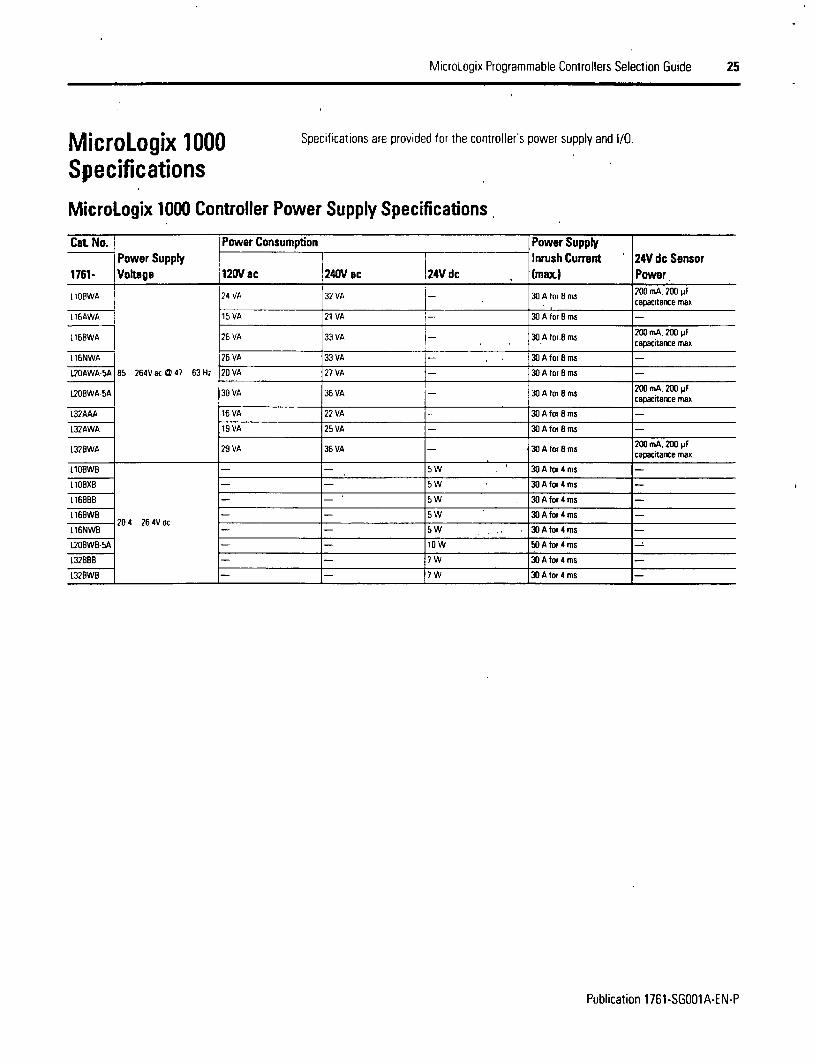
M icroLogix 1000 Specifications are provided for the controller's power supply and 1/0.
SpecificationsMicroLogix 1000 Controller Power Supply Specifications
Cat No. Power Consumption Power SupplyPower Supply Inrush Current 24V dc Sensor
1761- Voltags 12V ac 1240V ac 24V dc . (max) Power1,1OBWA 24 VA 32 VA 30 A for B ms 200A.200I __ ____ ___ ____ ____ ___ capacitarce maxL16AWA 15VA 21 VA 30AforBms _
26 VA 33 VA 30 A tor.8 ms 200 mA, 200 pFT;;~~ apacitance max
[16NWA 26 VA 33 VA _ , 30 A for 8 ms
L20AWA-5A 85 264V ac @ 47 63 Hz 20 VA 27 VA 30 A for B ms
UOBWA-SA 30 VA 36 VA 30 A for 8 ms 200 mA. 200 pFL2OBA-SA30 -capacitance max.
L32AAA 16 VA 22 VA 30 A for 8 ms
L32AWA 19 VA 25 VA 30 A for 8 ms
L32BWA 29 VA 36 VA - 30 A for 8 mrsc 200 mA. 200 pxcapacitarice max.
11OBWB _ S W 5 30 A for 4 ms
I1OBXB S- W 30 A for 4 ms
L16BBB S- W 30 A for 4 ms
116BWB -_ S W 30 A for 4 ms _20 4 264V dc _ _ _ _ _ _ _ _ _ _
L16NW9 _ SW W 30 A tor 4 ms _
L20BWB-5A - OW 50 A tor 4 ms
L32BBB - 7 W 30 A tor 4 ms
L32BWB - 7 W 30 A tor 4 ms
Publication 1761-SG001A-EN-P

26 MicroLogix Programmable Controllers Seleclion Guide
MicroLogix 1000 DC Input Power Requirements Based on l/O Usage
1761-LlOBWB Typical Power Requirements ' 1761-L10BXB. -L16BBB Typical Power Requirements
47 61
-A 4
00 2 4 6 8 10 0 2 4 6 a to 12 14 16
I/O Points Used UO Points Used
1761-L16BWB ETypical Power Requirements
tr4
2C 1 _
0 2 4 6 8 10 12 14 16jO Points Used
1761-L32EWB Typical Power Requirements
12 U
10 _
0 4 8 12 16 20 24 28 32| 110 Poinms Used
~- lo
I 0 *
1761-L32BBB Typical Power Requirements
U 4 5 12 lb zu 24 zu 32MO Points Used
1761-L20BWB-SA Typical Power Requirements
S I10v 6 ~
; 34--3
0 2 4 6 8 10 12 14 16 18 20lO Points Used |
l _ _ _J
Publication 1761-SGOO1A-EN-P

MicroLogix Programmable Controllers Selection Guide 27
MicroLogix 1000 Controller Digital Input Specifications
Specification 120/240V ac Controllers 1 24V dc Controllers 24V ac ControllersOn-State Volage Fange |7 132V ac 14 26 4V dc max C 55 'C (131 F) 16 26 4V dc max G 55 'C 1131 'F)
114 300Vdcmax ( 30'C (86 JF 16. 300Vdc max G30 C186 FI
Oft-State Voltage Range 0 20V ac 0 5V dc o 3V ac
Operating Frequency * 47 63 Hz standard inputs 10 kHz Imax 47 63 Hihigh-speed inputs 6 6 kHz lmax.i
On Delay - 20 ms standard inputs selectable from 05 16 ms On Delay 20 msSignal Delay Imax Of Delay * 20 ms high-speed inputs selectable trom 0 075 16 ms Ott Delay * 20 ms
On-State Current (min I 5 0 mA 6 79V ac @ 47 Hz 12 5 mA i 14V dc 3 0 mA G 18V ac
On-State Current Inominall 12 0 mA C 120V ac @ 60 Hz 160 mA C 24V dc 8 0 mA C 24V ac
On-State Curent Imax) 16 0 mA 132V ac 6 163 Hz 12 0 mA @ 30V dc 12 0 mA 0 30V ac
Oft-State leakage Current Imax I 2 5 mA 1 5 mA 1 0 mA
Nominal Impedance 12 k at 50 Hz. 10 W f 60 Hl 3 kS2 3 k)Maximum Inrush Current 250 mA max * - *
* 1761-1t6NwA aw 1761-116NVe convioller it nor suppsio hrgh speed pulr ewn Wie,, us'n.24Vdc spurs* lo ieduree im-nusht maimum ro i3 mA bpi a 6f?. W essisi in se-.es w Tt tn tns le on siale noulige *rncease Ts 97v ac as a resuI
MicroLogix 1000 Controller Digital Output Specifications
Specification Relay FET TriacOperating Voltage Range 5. .25V ac 204.. 26 4V dc 85 264V ac5.. 264V ac
Continuous Current per Point (max.) See MicroLogix 1000 Relay Contact Rating 1 0 A @30 C (1131 'F) 1.0 AG 30 S C (8 31F)
Continuous Current per Common Imax.) 80 A 3 A tor [LOBB8 and L16BBB . 6 A6 A for L32BBB
Continuous Current per Controller (max I 1440 VA 3Aor tO and L6BBB 1440 VA
On-State Current (mi n. 10.0 mA 100 mA
Otf-State Leakage Current Ima O mA 1m mA 2mA 0 132V ac4 5 mA 0 215AV ac
On Delay = 0insa On Delay r D ms On Delay= 106.ms 0 60HzSignal Delay (max.) - resistive load OT1 Delay' 10 ms Ott Delay 1 i ms Ott Delay = 11.0 ms
Surge Current per Point Ipeak) n/a 4 A for 10 ms 10 A tom 25 ms *
* 'lepeatability is orce every 7 seondis at 55'C (131 'F)
MicroLogix 1000 Relay Contact RatingMaximum Amperes Amperes VoltamperesVoltage Make Break Continuous Make Break240Vac A
I 2.5 A 1 SOO VA lSO VA120Vac 1A15125Vdc 022 A 1 OA
24V dc 1.2 A * 20A A
* 0a dc vCirIagE appi-casrons. lhe makeblEak ampere rauiri brx relay contats can te ueierm-ned by didindrg 28 VA by the applied dc voltage Fo- example.21 VA/48V dc = D 5A A lo, dc voliauo applicadion less than 48V. Ithe make/break rating tar relav contacs cannol exceed 2 A. Fx dc voltageappicauns greaie Tria, I&. Vthe make/Oreau ratings tar relay coniact canrinoi eceed 1 A
Publication 1761-SG001A-EN-P

28 MicroLogix Programmable Controllers Selection Guide
MicroLogix 1000 Controller Analog Input Specifications
Specification 1761-L20=ocx-BAVoltage Input FRange * *10.5. .05Vdc
Current Input Range * -21 .421 mA
Inout Coding 1-21 421 mA. -10 5 ... 410 5V dc .32 768 .. 432 767
Voltage Input Impedance 2101f
Currene Input Impedance 160 ki:
Irxut Resolution 4, 16 bit
Non-linearity <0.002%
Overall Accuracy 0 55 'C (32.. 131 'F1 ±07% ot full scale
Overall Accuracy Dnrit 0 .55 'C (32. 131 'F) (max I ±0 176%
Overall Accuracy 0l 25 'C 177 'Fl (max.) ±0 5259%
Llpdate Time selectable from A .. .100 ins
Voltage Input Dvervoliage Protection 24V dc
Current Input Overcurrent Protection ±50 mA
Inout to Output Isolation and Field Wiring to Logic Isolation 30V rated working voltage. 500V isolation Rest 60 Hz for 1 sl
a The two voltage InpuS accept 10Ds i.c The tMo Crurfe inputs accept ±21 mA* The analog iniput uaclate tate vnd inpur iesoluion aire a tunction of the inpu fillet selection.
MicroLogix 1000 Controller Analog Output Specificotions
Specification 1761-L2Obcx-5AVoltage Output Range 0.. .1Vdc
Curtent Output Range. 4... 20 mA
Non-lineanty 0.02%
Step Response 2.5 ms fat 95%)
Load Range -Voltage Output 1tk .- fD
Load Range -Current Output 0... 5000
OutputCodingt 14 20mA.0 ... .1Vdcl 0.32767
Voltage Output Miswiring and Current Output Miswiring can withstand shon circuit
Output Resolution 15 bit
Analog Output Setting Time 3 ms (maximum)
Overall Accuracy 0. 55 'C (32 ... 131 IF) ±1.0% of full scale
Overall Accuracy Drift 0 .55 eC (32... 131 FI Imax.l ±0.28%
Overall Accuracy 0 25 'C (77 IF) Imax.l - Current Output 0.2%
Field Wimng to Logic Isolation 30V rated working voltage 500V isolation
* The analog output can be contgured ho either vohage 10 ..+... t ld or cuient (4 . 20 viAl.
Publication 1761-SG001A-EN-P
MicroLogix Programmable Controllers Selection Guide 29
Step 6 - Select
• controller - review power and 1/0configurations to select a controllercatalog number; see power supply and1/0 specifications for more detailedinformation
* accessories - memory and real-timeclock modules
* record your selection in the SelectionRecord (starts on page 60)
Select MicroLogix 1200 Controllersand Accessories
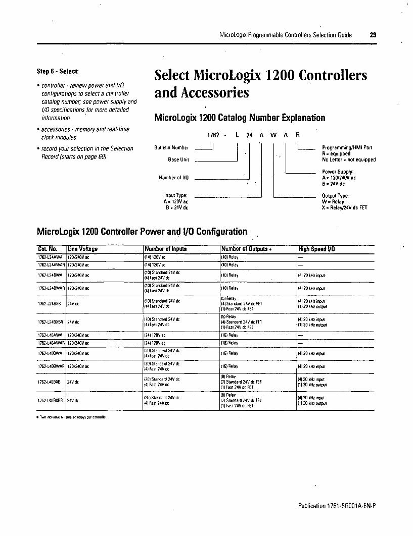
MicroLogix 1200 Catalog Number Explanation
1762 - L 24 A W A R
Bulletin Number I
Base Unit
Number of 1/0
Programming/HMI PortR = equippedNo Letter = not equipped
Power Supply:A= 120/240V acB=24Vdc
Input Type:A= 120VacB = 24V dc
Output Type:W- RelayX = RelayJ24V dc FET
MicroLogix 1200 Controller Power and U/O Configuration,
Cat No. Une Voltage Number of Inputs Number of Outputs * High Speed 11O1762-L24AWA 120/240V ac 1141120V ac 110) Relay
1762-L24AWAR 120/240V ac 1141 120V ac (110) Relay
1762-L24BWA 120Q240V ac 111 Standard 24V dc 110) Relay 14120 kHz input
1762-U24BWAR 120/240V ac 1101 Standard 24V dc 110) Relay (4120 kHz input(4) Fast 24V dc
1101 Sas a 24Vdc 151 Relay 14120 kHz input1762-L24BXB 24V dc 1101 Ftand24Vd 141 Standard 24V dc F1 t14) Fast 24V dr I ~1I1Fas?24V dc FE1 ()2 ~ mt
11 01 Standard 24V dc 116 Relay 14120 kHz input176242BXB NVd (401 fast 24V dc 141 Standard 24V dc FEI 11 20 kHz output1I762-L 40BXBR 24V dc IllFas 2V 2 z
176*-1L4AWA 120/240V ac 1241 120V ac 1161 Relay
1762-L40AWAR t20/240V at 1241 120V ac 1161 Relay
11762-4401WA 120/240V ac 1201 Standard 24V dc 1161 Relay 141 20 kHz input14) Fast 24V dc11610WR1214Va 201 Standard 24V dc 1161 Relay 141 20 kHz inputt762L40WAR 120240at 4) fast 24V dc
12)Sadrd2Vd 81 Relay 141 20 kHz input1762-1.408X 24V dc 121 astadr 24V dc 171 Standard 24V dc FET 11 120 kHz outpuI
141 Fas 24V1dcIl Fast 24V dc FET
12)Sadrd2Vd 81 Relay 141 20 kHz input172120B12VdcJI astadr 24V dc 17) Standard 24V dc FET 11 120 kHz outputI72 L 4 B B 04 C4 ) F s 4 cI l F a st 2 4 V d c FE T
*o iwd !dually solaree relays pe, COM10oter
Publication 1761-SGOO1A-EN-P
30 MicroLogix Programmable Controllers Selection Guide
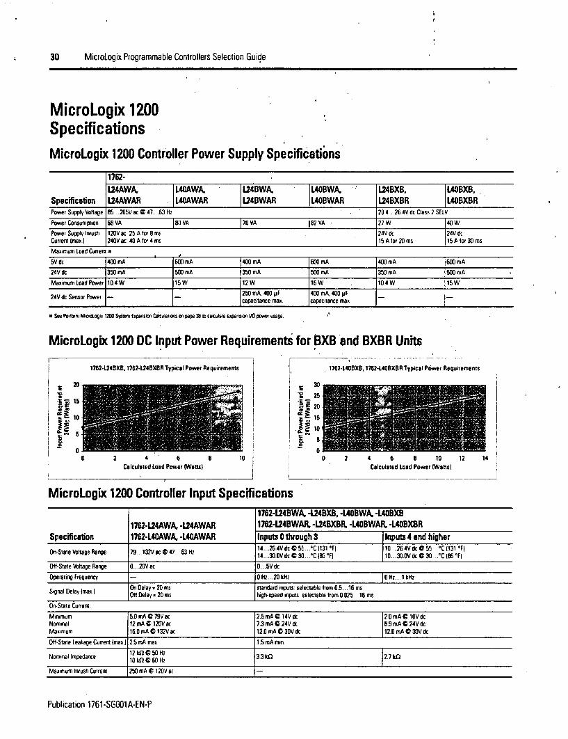
MicroLogix 1200SpecificationsMicroLogix 1200 Controller Power Supply Specifications
1762-L24AWA, L40AWA, L24BWA, L40BWA. L24BXB, | L40BXB,
Specification L24AWAR L40AWAR L24BWAR L40BWAR L24BXBR L4OBXBRPower Supply Voltage 85.. .265V K 0 47 63 H-t 20 4 . 26 4V dc Class 2 SELV
Power Consumption E68 VA |80 VA 17O VA 182 VA 27 W 4OW
Power Supply Inrush 120V ac. 25 A tof 8 m 24V dc 24V dcCurrent (max.) 240V ac: 40 A lot 4 irs 1S A for 20 ms 1S A lor 30 ms
Maximum Load Current *
5V dc 400 mA 600 mA 400 mA 600 mA 400 mA 600 mA
24V dc 350 mA 500 mA 350 mA 500 mA 350 mA 500 mA
Maximum load Power 104 W 15 W 12 W 16W 104 W 15 W
24V dc~ Sensor Power - 250 mA, 400 yF 400 mA, 400 yFI capacitance max capacitance max
* See Perform Miciodogix 1200 System Exoansion Cakulations on page 36 to calculate expansion l/O power usage.
MicroLogix 1200 DC Input Power Requirements for BXB and BXBR Units
1762-L24BXB, 1762-L24BXBR Typical Power Requirements | 1762-L406XB, 1762-L406XBR Typical Power Requirements
Si20 30 | !|w2i1 1z-|1
15
~~10E 2e 5 iI
0 2 4 6 8 1 2 4 6 a 1O 12 1Calculated Load Power IWatts) | Calculated Load Power IWatts)
MicroLogix 1200 Controller Input Specifications1762-L24BWA, -L24BXB, -L40BWA. -L40BXB
1172-L24AWA, -U24AWAR 1762-L24BWAR -L24BXBR, -L4UBWAR, -L4OBXBRSpecification 1762-L4U AWA, -UO4AWAR Inputs 0 through 3 Inputs 4 and higherOn-Sae Voltage Flange 179. .. 132V 8c G 47.. .63 Hz 4... *.264V dc C 55. ... IC 31131 1F0 10. ..264V dc G 55..°C 1131 IF)
1 14... 3.0VdcC30 ... IC18°FF) J 10. .30.OVdc 30 ..°C 186°eFI
OH-Sate Voltage Range 0.. .20V ac 0... 5 dc
Operating Frequency - 0 Hz. .20 kHz 1O Hz. .1 kHz
SignalDel Imaxl On Delay 20 ms standard inputs selectable from 0.5.. 16 msay IOtt Delay - 20 mis high-speed inputs selectable from 0.025.. .16 ms
On-State Current:
Minimum 5.0 mA G 79V ac 2.5 mA C 14V dc 12.0 mA C 1OV dcNominal 12 mA C 120V ac 7.3 mA C 24V dc 8.9 mA C 24V dcMaximum 16.0 mA C 132V ac 12.0 mA C 30V dc 12.0 mA G 30V dc
OHf-Staie Leakage Current (max.) 2.5 mA max. 1.5 mA min.
Nominal Impedance |12 Gf 6C0 Hz 3.31 2.7 kO10 kfl @0 lI6 az
Maximum Inrush current 25 mA C 120V ac
Publication 1761-SGOOIA-EN-P
MicroLogix Programmable Controllers Selection Guide 31
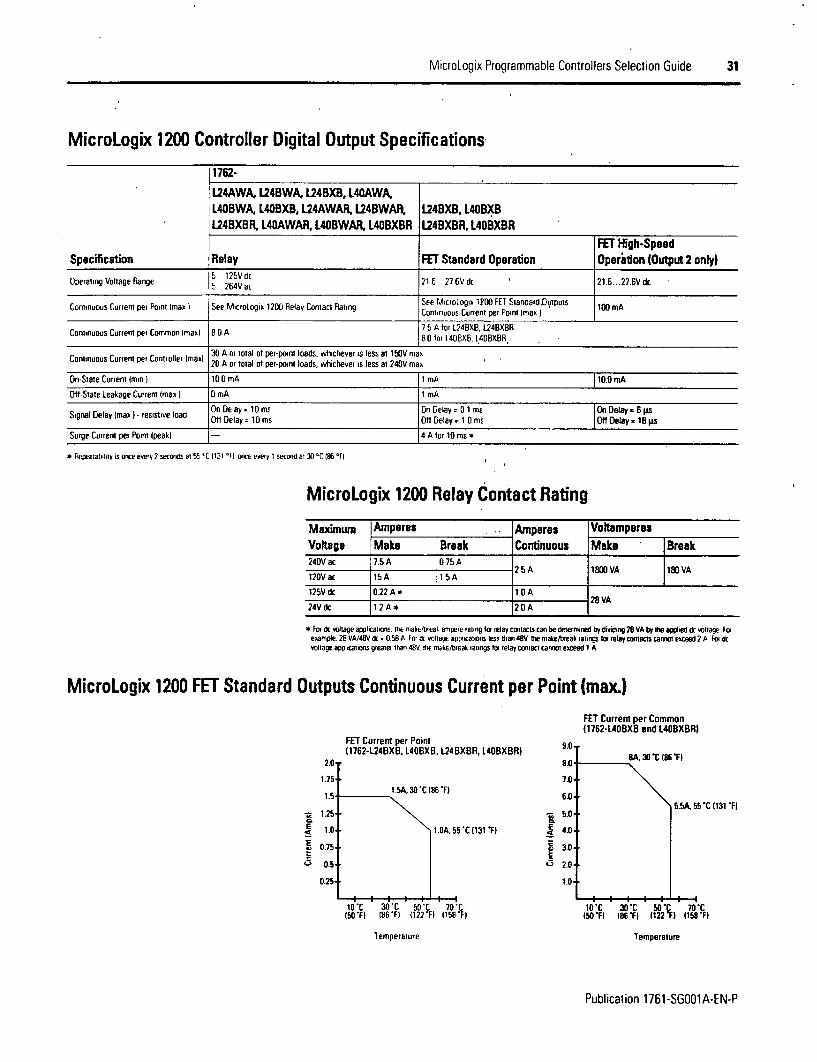
MicroLogix 1200 Controller Digital Output Specifications
1762-
L24AWA, L248WA, L24BXB, L40AWA,L40BWA, L40BXB, L24AWAR, U4BWAR. U4BXB, L40BXBU24BXBR, L40AWAR, L40BWAR, L40BXBR L24BXBR, L4OBXBR
FEY High-SpeedSpecification Relay FET Standard Operation Operition lOutput 2 only)Operating Voltage Range 2 125V dc 21 6 27 6 vdc 21 6 ..27.6V dc1~ ?64V ac
Continuous Current pet Point max) See MictroLogix 1200 Relay Contac t See MicrlOgng 1?O)l StaidardDuiputs 100 mAContinuous Cunent Per Point Imao)
7 S A tot U24BXB U24BXBRContinuous Curtent per Common Imax 8 0 A 8 0 for I40BXB. I40BXBR
Continuous Current per Controllet Imaxl 20 A or total of per-point loads, whichever is less at 150V max
On-State Current Imm) 10 0 mA 1 mA 10.0 mA
Ott-State Leakage Current (max I 0 mA I mA
Off Delay= I 10 s On Delay1 O iMs On Delay =16 psSignal Delay (max)I - resistive load Ott Delay= ID1 ms Off Delay I 01 ms |Off Delay - 68 js
Surge Current per Point 1peak) - 4 A for 10 ms *
* leoealmbilty is orte evey 2 seconis er 5ss'C 1131 'Fl once every 1 seconua a 30 IC86 °Fl
MicroLogix 1200 Relay Contact Rating
Maximum Amperes . Amperes VoltamperesVoltage Make Break Continuous Make Break240V ac 75 A 0 75 A
2.S A 1800 VA 1ic10VA120Vac 15A 1 5A
125V dc 0.22 A 1.0 A28 VA
24V dc 1.2A* 2.0 A
* For * voltage applcatons. mte makeNeial amtpere raring lot relay contacts can be determined by dividing 2E VA by the aplied tic voohage Forexample. 2E VA/48V ac = 0 5B A For dc voirane appncaurons less than 48V. the make/break ratings Ito relay contacts cannot exceed 2 A For dcvolItae ayplicatmons greater than 48V. tie irke/trseak ratings lIo relay contract cannot exceea 1 A
MicroLogix 1200 FET Standard Outputs Continuous Current per Point (max)
FET Current per Common11762-L40BXB and L40BXBRI
FET Current per Point(1762-L24BXB. L40BXB, L24BXBR, L40BXBR) 9.0-
8D1
E
iS
1.75.
1.5.
1.25*
1.0.
0.75.
t5A, 30'C1867)
1iDA. 5
I. 30 0* .
55 1131 TI
7.0'
-;, 5.0'
E 4.0.
I- 3.0'
1.02
8A 30 (86 TI
UaFSA SS-C (131 FI
0.25-
50 FI 186-&1 i122 F1 1158 Fj
Temperature
10-C 30 C 50P 70 C(s0 FI 186 TI (122 F) /158 F1
Temperature
Publication 1;761-SGOO1A-EN-P

32 MicroLogix Programmable Controllers Selection Guide
MicroLogix 1200Memory and Real-Time Clock Modules
SM.U.. . . .
The controller is shipped with a memory module port cover in place. You can order thememory module, real-time clock or combination module to suit your needs.
Real-Time Clock (1762-RTC)* Allows for time/date scheduling
* Sell-contained battery provides long-term,time base
Memory Module (1762-MMI)Memory modules allow:
* user programs and data to be stored as backup
* transport programs for use with other controllers
* special safety/security features for press control and other critical applications
* auto-recovery, through a power cycle, after a controller fault
* comparison of programs
* data file and memory module write protection
* removal/insertion under power
Combination Memory and Real-Time Clock Module(1762-MM1 RTC)- Provides all real-time clock and memory back-up functions of the 1762-RTC and 1762-
MM1 modules
Publication 1761-SG001A-EN-P

MicroLogix Programmable Controllers Selection Guide 33
Step 7 - Select:
* 1/0 modules - digital, analog andtemperature
* perform system expansion calculations
* record your selections in the SelectionRecord (starts on page 60)
Select MicroLogix 1200 1/OMicroLogix 1200 I/O expansion modules provide superior functionality at low cost Avariety of modules complement and extend the capabilities of MicroLogix 1200 controllersby maximizing the flexibility of I/0 count and type.
The MicroLogix 1200 system design allows modules to be either DIN rail or panelmounted. The DIN latches and screw mounting holes are an integral part of the packagedesign.
Controller I/0 can be expanded using up to 6 expansion modules per controller (dependingon power budget).
Advantages* Rackless design, eliminating added system costs and inventory
* Small footprint with high density I/O, minimizing panel space requirements
* Integral high-performance I/O bus
* Software keying to prevent incorrect positioning within the system
* Feature-rich I/O functionality addresses a wide range of applications
* AC/DC relay, 24V dc, 120V ac and 240V ac voltages
* Thermocouple/mV and RTD/Resistance temperalure input modules
Available Modules 1762 Expansion I/O Modules
Cat No. DescriptionDigital:
1762-iA8 B-Point 120V ac Input Module
1762-108 B-Point Sink/Source 24V dc Input Module
1762-1016 16-Point Sink/Source 24V dc Input Module
1762-OA8 B-Point 120/240V a Triac Output Module
1762-OB8 6-Point Sourcing 24V dc Output Module
1762-OB16 16-Poim Sourcing 24V dc Output Module
1762-OWB B-Poim AC/IDC Relay Output Module
1762-OW16 16-Point AC/DC Relay Output Module
1762-OX61 6-Point Isolated AC/tC Relay Output Module
Analog:
1762-IF4 4-Channel Voltage/Current Analog Input Module
1762-0F4 4-Channel Voltage/Current Analog Output Module
1762-1F2012 Combination 2-Channel Input 2-Channel Output Voltage/Current Analog Module
Temperature
1762-IR4 14-Channel RTD/Resistance Input Module
1762-114 I4-Channel Thermocouple/mv Input Module
Publication 1761-SG001A-EN-P
34 MicroLogix Programmable Controllers Selection Guide
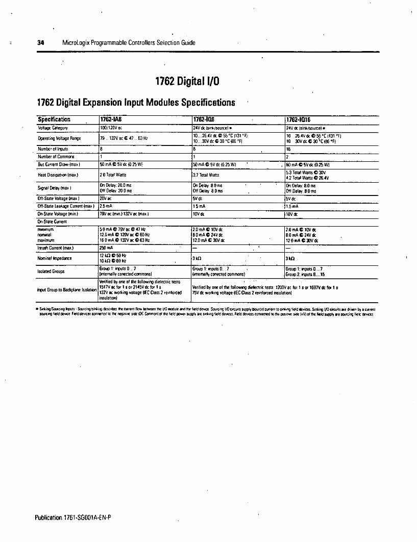
1762 Digital l/O
1762 Digital Expansion Input Modules Specifications
Specification 1762-lA8 1762-11 1,1762-la16Voltage Category 100/120V ac 24V dc Isink/sourcel * 24Vdc Isink/sourcel *
Operating Voltage Range 79 .132Vac C 47.. 63 Hz 10 26 4Vd G S S C(131 F) 10 30 Vdc C 30 C1B 3 ° F)
Number of inputs B 8 15
Number of Commons 1 1 2
Bus Curren Draw Imax 50 mA D 5V dc (0.25 W} 50 mA G 5V dc (0.25 WI 60 mA G 5V dc l0.25 WI
Heat Dissipation (max.) 2 0 otal Waits 37 Total Watts 5.3 Total Watts @ 30V. .2 lotal Watts C 26 4V
On Delay: 20.0 ms On Delay: 8.0 ms On Delay: 8.0 msSigna Delay Imax I Ofl Delay 20 0 ms Off Delay: 8 0 ms Ofl Delay: 8.0 ms
Off-State Voltage Imax.) 20V ac SV dc 5V dc
Otf-State Leakage Current Imax | 2.5 mA 1.5 mA 11.5 mA
On-State Voltage (min.) 79V K Imin.) 132V ac (max I 1OV dc 10V dc
On-State Current:
minimum 5.0 mA G 79V ac X 47 Hz 2.0 mA 10V dc 2.0 mA C 10V dcnominal 12.0 mA G 120V ac G 60 Hz 8.0 mA 24V dc 8 0 mA C 24V dcmaximum 16 0 mA G 132V ac G 63 Hz 12.0 mA G 30V dc 12.0 mA 30V dc
Inrush Current Imax.) 250 mA
Nominal Impedance 12 kIl 50 Hz 3kQ 3 S10 kD C 60Hz
Isolated Groups Group 1: inputs 0 . 7 Group 1: inputs 0.. .7 - Group 1: inputs 0 ...7(internally conecned commons) (internally conected commons) Group 2: inputs E. 15
Verified by one of the following dielectnc tests:1517Vac for 1 s or2145Vdc for 1 s Venfied by one oftthe following dielectric tests 1200YV ac for1 s ot 1697Vdc for I s
Input Group to Backplane Isolation 132V ac working voltage (IEC Class 2 reinforced 75V dc working voltage IIEC Class 2 reinforced insulation)
insulation)
* Sirring/oruicing itputs -Souvring/sinking destribes me current ibw betweeren Ste / rodule anrd te livd device Souircing 1/0 circuits supply Wsouce) current to sinkig ield devices. Sinking W circuits wre driven by a currentsouicing lield device Field devices ocnnerted tort e negative side (DC CromN) of ie lielCd pwel supply are siking tivld devices. Field devices cronnected io the positive side H4VI of the field supply are sourcing field devices
Publication 1761-SGOOlA-EN-P
MicroLogix Programmable Controllers Seleclion Guide 35
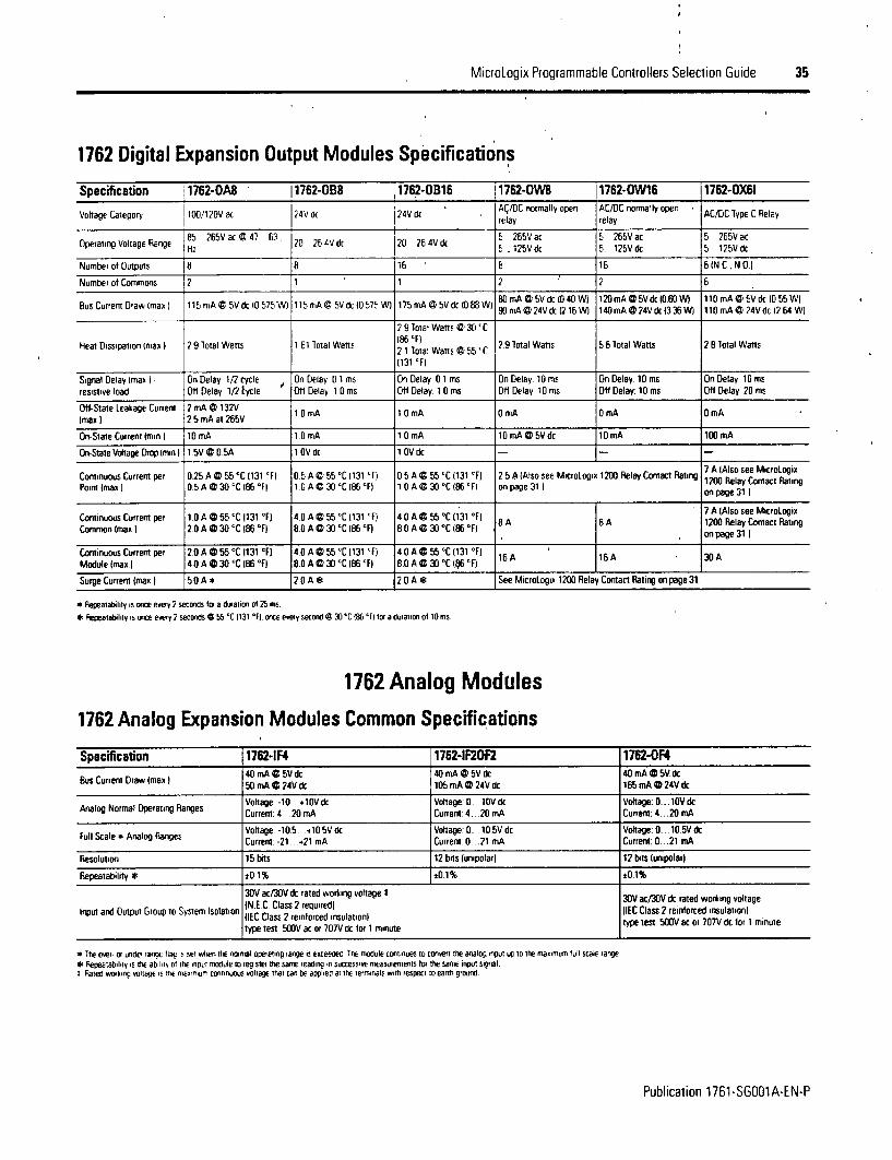
1762 Digital Expansion Output Modules Specifications
Specification 11762-OAB 1762-OBS 11762-OB16 1762-OWB 1762-OW16 1762-0X61
VolageCategory I100/120Vat ?4V d 24V . Ac/DC rwrmally open AC/DC normally openrelay relay A/Clp ea
O 85 265V ac C 47 63 20 264Vd 20 26S4Vd 265 ac 5 265V ac 5 265V acH 2 2 1 25V dc 5 125V dc 5 125V dc
Number of Outputs 8 8 16 8 16 6 IN C. N O)
Number of Commons 2 1 1 2 2 6
80OmA@ 5Vdkc(D40OWl 120OmAG V dc10 60 Wl 110rnA P5V dc 10b55WlBus Current Drawvvmax ) 15 imA @ 5V dc 10 575Wl 115mA C SV dc 10575 W) 175 mA C) 5Vdc 10 88 W O 90 mA C 2V 16Wl 140mA@24Vdc(360W 1 110 mA i 24Vdc 12 64 W)
2 91oia Wans*ei301C
Heat Dissipation (max) 2 9 iotal Wars 161 lat Watts 21 ota) Watts SS C 2 9 otal Watts 5 6 lotal Watts 2 l1otal Watts
(131 'F)
Signal Delay Imax ) - [On Delay 1/2 cycle On Delay 0 1 ms On Delay 01 ms On Delay. 10 ms On Delay 10 ms On Delay 10 mSresistive load [Otl Delay 1/2 cycle Ott Delay 10 ms Ott Delay 1 0 ms Oft Delay 10 ms Off Delay: 10 ms Off Delay 20 ms
Ott-Slate Leakage Current 2 mA a 132V 10 mA 10 mA OrmA O mA OmA(maoI 2 5mA at 265V lrAlm m m
On-State Current (min 10 mA 1 0 mA 10 mA 10 mA @ SV dc 10 mA 100 mA
On-State Voltage Drnop mm I 1 5V C 05A I 0V dc 1.OV dc - -
Conoruousurretper 025A@5'Ct~l ') os~s~'l131 F) 0A@55C)13 'F ~ ~ Micotngot70ARe(AadsoI seeAlsMseeMicrlogxContPuous Curren per 025 AC 5 'xC 1131 F) OS A ' CS -C 1131 Fr 0 5 A l S S'C 131 AFl 2 5 A (Also see MicroLogix 1200 Relay Contact Rating. 1200 Relay Contact RatingPoint (max I 0 S A 0 30 -C iDi °FI' I 0 A C 30 -C 86 IF) 1 O A G 30 'C 186 IFl on page 31. on page 31
Continuous Current per 1 0 A @55 'C 1131 'F) 4.0 A G S 'C jl31 F) 4 0 A G SS °C (131 °FI 8 A 7 A 1 Also see MicroLogiComnm- 0@0'IOF o @jC (131F) 4,0A@~C 5 I ( 3 F) B 8A 1200 Relay Contact RatingCommon (max)i 2,0 A G 30 'C 16ti °F eo A g 30 GC (86 -FI 8.0 A 0 30 'C i86 °FI .. on page 313)
ContinuousCurrent pet 2?0A@55C1131 'F) 4.0A@55 C1l31 'F) 4 40A155-C131'F) 16A 16A 30AModule Imax.l 4.O A @ 30 'C 186 IF) 8.0 A D 30 IC 186 'Fl 8.0 A @ 30 -C (161 F) 16_A_16_A_30A
Surge Current imaxo) 5 0 A * 2 0 A 1 2.0 A * See Micrologia 1200 Relay Contact Rating on page 31
* Flepearability is once every 2 seconds tfa a duraion o0 25 ms* repeauauhlity is once every 2 seconds e 55 'C 1131 'Fl. once every second C 30'C OO 'F) lot a duation ot imns.
1762 Analog Modules
1762 Analog Expansion Modules Common Specifications
Specification 1762-1F4 1762-IF2OF2 1762-0F440 mA @5V dc 40OmA W5V dc 40 mA @5V dc
Bus Current Draw (max a 50 mA I 24V dc 40 mA 24SV k 165 mA 24V dc
Voltage -10.-+l10Vdc Voltage: 0.. 0V dc Voltage: 0 ... OV dcAnalog Normal Operating Ranges Current: 4 20 mA Current- 4.. 20 mA Current: 4 . 20 mA
Full Scale a Analog Ranges Voltage -105 4IO5Vdc Voltage: 0. 10.5Vdc Voltage:0 10.5VdcCurrent. -21 +21 mA Current: 0 21 mA Current: 0 ..21 mA
Resolution 15 bits 12 bits (unipolar) 12 bits (unipolar)
Repeatability * s01 ±0.1% !0.1%
30V ac/30V dc rated working voltage I 30V ac/30V dc rated working voltage
Input and Output Group to System Isolation IEC Class 2 reinforced insulation)IIEC Class 2 reinforced insulation) type test: 500V ac or 707V dc for 1 minutetype test: 500V ac or 707V oc for 1 minute
a 1he ov er a unde-rangE aag ,s ser wvven the normal ouerating range is evceeoet The module coniinues to convenr the analog input uo ID Ihe mnalurn hull scale rangeR elepeatubir ir tsne att th o' thE vIsp morule to reuiser trhe same leauioinm successove measuiements loi the same input signal.
turated WOkniri voltal ite mulimum coninuous voltage that can be applies at the terminals with espect to earth ground.
Publication 1761-SGOO1A-EN-P

36 MicroLogix Programmable Controllers Seleclion Guide
1762 Analog Expansion Input Modules Specifications
Specification 1176244 * 11762-4F20F2Number of Inputs 4 difteremial bipolarl 2 differential (unipolar)
Uodate Time (typical) 130, 250, 290. 45i0 530ms Iselectablel 2 5 ms
A/ID Convener lype Successive approximation Successive approximetion
Common Mode Voltage Range * :27V ±27V
Common Mode Rejecion * > 55 dB C 50 and 60 Hz > 55 dB C 50 and 60 Hz
Non-linearity (in percent full scale) :0 1% TO.1%
lypical Overall Accuracy ± 0D 3% full scale at 0 55 'C 132.. 131 'F) 20.5% tull scale at 0 55 C (32. .131 'F)±0 24% full scale at 25 IC 177 IF) 0 3% full scale at 25 IC (77 IF)
Input Impedance Voltage Terminal 200 klD Voltage Terminal 200 kfCurrent Terminal 275 D Curtent Terminal 250 n2
Current Input Protection ±32 mA i32 mA
Voltage Input Protection :30V t30V
Channel Diagnostics Over or under range or open circuit condition by bit reporting for analog inputs
* For poper operarion. both rhe plus and minus inpur terminals musr be irihin M7v of analog common.* Vm . t V; p, ACI V,, I O lincluites otset. gain. non-fiveariry aN repeatrabiliry erritonl eW
1762 Analog Expansion Output Modules Specifications
Specification 1762-lF;2OF2 1762-OF4Number of Outputs 2 single-ended (unipolar) 4 single-ended rbipolarl
Update Time Itypical) 4.5 ms 2.5 ms
D/A Convener Type Resistor strng R-2R Ladder voltage switching
Resistive Load on Current Output 0.. 500 n lincludes wire resistance) 0 . 500 Q lincludes wire resistance)
Load Range on Voltage Output >1 In > 1 kQ
Reactive Load, Current Output < 1 mH < 1 mH
Reactive Load. Voltage Output < 1 pF < 1 pF
Typical Overall Accuracy * k% full scale G 0 . 55 'C 132.. .131 IF) ±1% full scale C 0.. .55 °C (32 . 131 IF)t0.5% full scale G 25 'C (77 F ±0.5% full scale C 25 IC 177 IF)
Output Ripple, range 0 ..500 Hz(reterned to output tangel <±0.1% <±01%
Non-linearity (in percent full scale) <±0o.5% < ±0.5%
Open and Shon-Circuit Protection Continuous Continuous
Open Protection ±32 mA ±32 mA
* Iunclures onser, gain, riun-linemiy and rerpearabifity error terms.
Publicalion 1761-SG001A-EN-P

cI
MicroLogix P ogrammable Controllers Selection Guide 37
1762 Temperature Input ModulesUse these modules as a cost-effective means of addressing process applications thatrequire temperature nteasurement and control. Each channel can be individuallyconfigured using RSLogix 500 programming software. On-screen configuration allows youto choose the input type, filtering frequency, data format and status data. On-boardscaling is also provided-
1762 Temperature Expansion Input Modules Specifications
Specification 11762-rT4 1762-lR440 mA C SY dc 40 mA C SV dc0us Current Draw (max I SO mA C 24V dc 50 mA O 24V dc
Number of Channels 14 qnput changeis plus a CJ sensor 4 input channels
TherocoulesType J.K. 1 E. . S B. .CRTDs Platinum f385 and 3916). Copper (4261. Nickel 1672 andAccepted Inputs Themiocouples Typu es J60 nnV and i1D5 mV 6181. Nickel-Iron 1518)
Resistance Ranges 0 3000 Q)
Filter Frequency 10 Hz 1 kHz 10 Hz... 1 kHz
Temperature Units 'C or Ir °C or IF
Data Formats Raw/Pioportional. Engineering Units. Engineering Units x 10. Scaled-for-PID. Percent Range
Thermocouple Inputs: ±05 ±3 D'C ±-09 ±54 'F) depending on With Autocalibration enabled...Accuracy @ 25 'C 07 °F) thermocouple type RTD Inputs: ±0.2 . 6 °C ±0 36. ±1 08 °F) depending on RTD type
Millivolt Inputs S15 ±20 mV Resistance Inputs ±05 ±15 n depending on resistance value
0 5C 13 °F) tOH 10 IClS 1 ... 18 IF) depending on thermocouple type ' With Autocalibration enabledAccuracy @0. 0 55 C 132. 131 'F) ±08iof Inputs.S :L5.. tO RTD inpts:±0 4 .. ±11 'C 1±072 .. u1.98 'Fidepending on FITItype
Resistance Inputs ±0 25 .2.5 Q2 depending on resistance value
7 303 ms per enabled channel 4 CJC update time, depending on filterChannel Update Time (typical) selection ICJC update time is equal to the largest enabled channel's update 6. .303 ms per enabled channel, depending on filter selection
time.)
Channel Diagnostics Over- or under-range and open circuit by bit reporting Over or under range and open circuit by bit reporting
Calioration The module performs autocalibration on channel enable and on a configuration change between channels. You can also program the module to calibrateevery five minutes
115 dB minimum @ 50 Hz (with 10 Hz or 50 Hz filter) 110 dB minimum CD 50 Hz (with 10 or 50 Hztfiler)Common Mode Noise Rejection 115 dB minimum @ 60 Hz (with 10 Hz or 60 Hz filter) 110 dB minimum @ 60 Hz (with 10 or 60 Hz filteri
85 dB minumum @ 50 Hz (with 10 Hz or 50 Hz filter) 70 dB minimum @ 50 Hz Iwith 10 or 50 Hz filter)Normal Mode Noise Rejection 85 dB minimum @ 60 Hz (with 10 Hz or 60 Hz filterl 70 dB minimum @ 60 Hz (with 10 or 60 Hz filter)
Input Group to System Isolation 720V dc tor 1 minute 707V dc for 1 minute
Channel-to-Channel Isolation s1OV dc il0V dcJ :±0.1 IC (±0.18 'F) for Nickel and Nickel-Iron
Thermocouples @ 25 'C (77 'F) and 10 Hz filter selected ±02 'C ItO.36 1 F) forN other FITE) inputsRepeatability* ±01 .t2 0 'C I±018 ±3.6 'F) depending on thermocouple type ±004 f2 for 150o ) resistances
Millivolt Inputs: ±6 pV ±0.2 Cf for other resistances
Input Impedance > 10 MD > 10 MD
* leceuatabilty is the ability o0 tMe inwrt n1cDuIe to ielsleu the same reading in successive rneasuiemetns o, tt* same Dpun signal
Publication 1761-SGOO1A-EN-P
38 MicroLogix Programmable Controllers Selection Guide
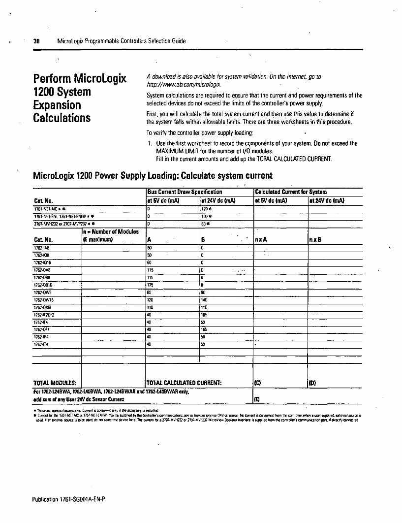
Perform MicroLogix1200 SystemExpansionCalculations
A download is also available for system validation. On the internet, go tohttp.//www.ab.com/micrologix.
System calculations are required lo ensure that the current and power requirements of theselected devices do not exceed the limits of the controller's power supply.
First, you will calculate the tolal system current and then use this value to determine ifthe system falls within allowable limits. There are three worksheets in this procedure.
To verify the controller power supply loading:
1. Use the first worksheet to record the cqmponents of your system. Do not exceed theMAXIMUM LIMIT for the number of 1/0 modules.Fill in the current amounts and add up the TOTAL CALCULATED CURRENT.
MicroLogix 1200 Power Supply Loading: Calculate system current
Bus Current Draw Specification Calculated Current for SystemCat No. at 5 dc ImA) at 24V dc (mA) at 5V dc (mA) at 24V dcmA)1761-NEI-AIC * t 0 120 *
1761-NE1-ENI, 1761-NET-ENIW * * 0 100 W
2707-MVH232 or 2707-MW232 * 0 80 *
n = Number of ModulesCat No. (6 maxdmum) A B . nxA nxB1762-lA8 50 0
1762-108 50 0
1762-1016 60 0
1762-OA8 115 0
1762-OB8 115 0
1762-4B16 175 0
1762-OW8 so so
1762-OW16 120 14D
1762-0(61 110 110
1762-lF20F2 40 105
1762-4F4 40 50
1762-0F4 40 165
176271R4 40 50
1762-114 40 50
TOTAL MODULES: TOTAL CALCULATED CURRENT: (C) ID)For 1762-1241BWA. 1762-L4OBWA 1762-124BWAR and 17624ADBWAR only,add sum of any User 2N dc Sensor Current IE1
* Thes e orplioenl accessories. Cerrent is crrnsumed only it the accessory is installed.Cu.rent or tbe 1761-NET.AIC or 1761-NE1ENIMW may be supplied by the conlrollef's commnunicarionos portotrm oran extersna 24Vot suce N tcurrent isconsuned tromrthe controlrlerten a user-sulied.externalsource is
used h an erleinal source is In Ie used. db n15 select the device here The current for a 2707-MVH232 or 2707-MVP37 MKcroView Wartor Interlace is supplied orno the contoller's cormunicetic n p or d t directly cornnecled.
Publication 1761-SGOO1A-EN-P

MicroLogix Programmable Controllers Selection Guide 39
2. Use the next worksheet to'verify that (Cl. (I) and (El do not exceed theMAXIMUM LIMITs. If the MAXIMUM LIMIT is exceeded, you will need toadjust your selections.
MicroLogix 1200 Maximum Load Current Verity that current values are within limits
Cat No. Load Current 5V dc 124V dc User 24V dc Sensor Current1762-L24AWA, U24AWAR Calculated Value IC) IDI1762-L24BXB. L24BXBR MAXIMUM LIMIT 400 mA 350 mA nla
Calculated Value IC) IDI (El1752-U24BWA. U24BWARlI
MAXIMUM LIMIT [400 mA 350 mA 250 mA
1762-L40AWA. L40AWAR Calculated Value CI 1011762-L40BXB. 140BXBR MAXIMUM LIMIT 1600 mA 500 mA
1762440BWA. L40BWAR Calculated Value IC) (DI (E)
MAXIMUM LIMIT e 1600 mA 500 mA 400 mA
3 Use the final worksheet to verify that the system is within thepowerloading limits of the controller.To use the worksheet, fill in the (C). (D) and (E) values where indicated.Then calculate Watts and add up the Total Watts. Verify that TotalWatts does not exceed the MAXIMUM POWER LIMIT. If theMAXIMUM POWER LIMIT is exceeded, you will need to adjust yourselections
MicroLogix 1200 Maximum Load Power: Verify that power consumption is within limits
5V Power Consumption 24V Power Consumption Calculated Watts MAXIMUMCat. No. Calculated Watts Calculated Watts, (sum of 5V and 24Y) POWE UMIT1762-U24AWA, L24AWAR IC) u 5V = W ID) x 24V = W W 104W
1762-U24BXB. L24BXBR ICI X 5V = W ID) x 24V = W _W 104W
1762-U24BWA. L24BWAR IQ I 5V = W IDI (IEI x 24V z W W112W
1762-L40AWA, L40AWAR ,0r X 5V W ID) a 24V = W 15W
1762-L40BXB. L40BXBR ICI 1 5V =W ID) x 24V = W W 15 W
1762-L40BWA. L40BWAR FCI x 5V = W (DI IEI x 24V = W W 16 W
Publication 1761-SGOO1A-EN-P

40 MicroLogix Programmable Controllers Selection Guide
Step 8 - Select:
* base unit - review power and 1/0configurations to select a catalognumber; see power supply and 1/Ospecifications for more detailedinformation
* processor - see notes at Step 1
* accessories - data access tool; real-timeclock and memory modules
* record your selections in the SelectionRecord (starts on page 60J
Select MlicroLogix 1500 Controllersand AccessoriesMicroLogix 1500 Base Unit Catalog Number Explanation
1764 - 24 A W A
Bulletin Number I I
Number of 1/0
Input Type:A = 120V acB = 24V dc
Power Supply:A = 120/240V acB =24V dc
Output Type:W= RelayX = Relay/24V dc FET
MicroLogix 1500Base Units
The Base Unit houses embedded inputs, outputs, power supply and the Channel 0communications port. The base unit also provides the interface to expansion 1/0 whenrequired by the application.
MicroLogix 1500 Power and l/Q Configuration
Cat No. Line Voltage Number of Inputs Number of Outputs High Speed UO1764-24AWA 120/240V ac 112 120V K 1121 Relay
1764-248WA 120/240V ac (4) Stamla 24V dc (121 Relay (8120 kHz input
WI) Stardard 24V dc (61 Relay 18I 20 k~tz input1764-288XB 24V dc 181 Fast 24V dc 41 SPanard 24V c 12)20 kHz pu
I 1 1121 Fast 24V dc FIT* Two indrividually itolaed relays ger base unit
MicroLogix 1500 Base Unit Power Supply Specifications
SpecRfication 1764-24AWA 1764-24BWA 1764-2nBXBPower Supply Voltage 85 ..265 Y ac @ 47 ...63 Hz 85 ..265 ac C 47 . 63 Hz 20.4 .. 30V dc
Power Consumption 70 VA 88 VA 30 W
Power Supply Inrush Cunent Imaxl I 240V ac.40 A for 4 rs 240 ac: 40 A for 4 ms 24V dc: 4 A or 150 ms
Maximum Load Current: *
5V dc 2250 mA 2250 mA 2250 mA
24V k 400 mA 400 mA 400 mA
Maximum Load Power 16 W 22 W 16 W
24V dc Sensor Power 400 mA 400 pF capacitance max. -
* See Petorm MICIOD1OP), 1511 System pxpansion Calculations on page 53 to calculate eRgnsoDn l/D) power usaoe* Do nos allow ithe total WC power consurned tN the SV Cc. 24V dc and sensor power outputa to exceed 22 W.
Publication 1761-SGOO1A-EN-P

MicroLogix Programmable Controllers Selection Guide 41
Choosing a Power Supply for the 1764-28BXBThis figure contains inlormation for selecting a power supply for applications using a 1764-28BXB base unit. Use the worksheets on page53 1o calculate the total power (Watts) consumed by the system. With that information, use the graphs below to choose a power supply-You can use either current or power, depending on how the power supply is rated.
Input Current Required Input Power Required
E
C-
CB0C,
C
1.4
1.2
0.8
0.6
0.4
0.2
0
I I I'IO,,'
W-�I � 11-10'
000-
;;Wo
I0 2 4 6 8 1 0 12 14 16 is
Wr,
c-
Cr
0~
tM-a
30
25
20
15
10
5
0
e-010I 10-00-
,.-IO
.ef. 1-410'
I I
0 2 4 6 a 10 12 14 16 18
Calculated Load Power (Wansl Calculated Load Power IWatts)
MicroLogix 1500 Base Unit Input Specifications
1764-24BWA and 1764-28BXB .Specification 1764-24AWA Inputs 0 through 7 Inputs 8 and higher
Or~Stte olageRage 9 13V c 047 63Hz14. 30.OV dc@G30 . C 16 Fl 1 0 .. 30OV dc @30..C (86 'F)OnStateVoltageRange 79 l32VacC47 63Hz 14 264Vdc@55 C1131 'Fl 1O 264Vdc 55 .c.C131 'Fl
Off-State Voltage Range 0 20V ac 0. 5V dc o. .5V dc
Operating Frequency n/a 1. 20 kHz 1 500 Hz
On Delay = 20 ms standard inputs selectable from 0 5. 16 msSignal Delay OfH Delay - 20 ms high-speed inputs selectable trom 0 025 16 ms
On-State Current
Minimum 5 o mA @ 79V ac 2.5 mA 1 14V dc 2.0 mA D 10V dcNominal 12 o mA e 120V ac 7.3 mA 24V dc 8.9 mA @ 24V dcManimum 160 mA es 132V ac 12 0 mA @ 30V dc 12.0 mA @30Vdc
OHf-State Leakage Current max.) 2 5 mA 1.5 mA 1.5 mA
Nominal Impedance 12 W at 60 Hz 3.3 kf 2.7 kn
Inrush Current Imax e 250 mA @ 120V ac -
Publication 1761-SGOO1A-EN-P

42 MicroLogix Programmable Controllers Selection Guide
MicroLogix 1500 Base Unit Output Specifications
1764-24AWA. -24BWA, -28BXB 1764-28BXB. . FET High-Speed
Specification Relay FET Standard Operation Operation (Output 2 and 3 only)
Operating Voltage Riange S .264V ac 20 4 26 4V dt
Continuous Current per Point Imax) See MicroLogix 1500 Relay Contact Rating i A 55 C 31 F) 100 mA1. SAC 30 TC 186 'F) 10m
Cominuous Current per Common lmaxl 80 A 6 0 A
24 A It 150V 18 AC 150VContinuous Current per Controller (max) 20 A C 240V 18 A C 240V
On-State Current Imin.j S mA C 79V ac 2 5 mA C 14V dc 12.0 mA C 1OV dc
Of-State Leakage Cunent Imax.) 0 mA 1 mA
Signal Delay (max I - resistive load 4 On Eilay . 10 Fm On Delay * 0 i ms On Delay * 6 lusON Delay sl10ms Off Delay .' M~os Off Delay s 18 ps
Surge Current per Poim (reak) 4 A for 10 msu
* Pepeatabilidy iF mce evey 2 seconits at S °C 1131 fl. once every 1 semrd aI 30 IC (8 IF)
MicroLogix 1500 Relay Contact RatingAmperes Voltamperes
Maximum AmperesVoltage Make Break Continuous Make Break240V eA 7.5 A 0.75 A 25 A 1800 VA 180 VA120Vac 15A 1.5A
125V dc 0.22 A * 1.0 A2S VA
24V dc 1.2 A * 2O A
* fmx fc voltage applications. the make/break ampere rating bm relay coniacts can be determined by dirding 28 VA by the applied rt notage Foeexample. 28 VAI48V &c * 0.5s A. For rt ltage aepplicarinns less than ANV te make/break ratings for relay crntacts cannot exrmed 2 A Fe icvoltage appicatirns greater than 48V. the maikebeak ratings fo relay conracr cannot exceed t A
MicroLogix 1500Processors
In the controller system, the processor unit provides logic processing, trim potentiometers,Run/Remote/Program mode switch, communications toggle push button and (using the1764-LRP processor) an electrically isolated RS-232 port. The processor also provides theinterface to the DAT, real-time clock and memory modules.
There are two processor units: 1764-LSP and 1764-LRP.
I
Publication 1761-SGOO1A-EN-P
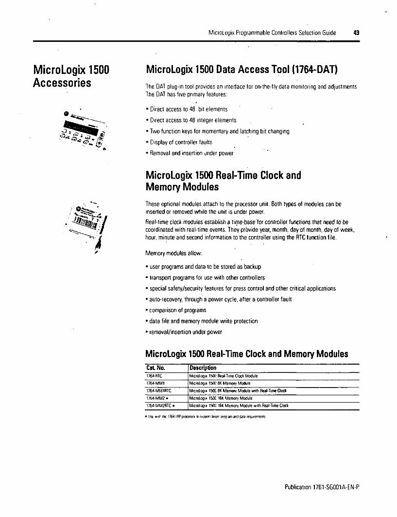
MicroLogix Programmable Controllers Selection Guide 43
MicroLogix 1500Accessories
* A '7____0-.":;
4.
MicroLogix 1500 Data Access Tool (1764-DAT)The DAT plug-in tool provides an interface for on-the-fly data monitoring and adjustments.The DAT has five primary features:
* Direct access to 48 bit elements
* Direct access to 48 integer elements
* Two function keys for momentary and latching bit changing
* Display of controller faults
* Removal and insertion under power
MicroLogix 1500 Real-Time Clock andMemory Modules
,.-#
These optional modules attach to the processor unit. Both types of modules can beinserted or removed while the unit is under power.
Real-time clock modules establish a time-base for controller functions that need to becoordinated with real-lime events. They provide year, month, day of month, day of week,hour, minute and second information to the controller using the RTC function file.
Memory modules allow:
* user programs and data to be stored as backup
* transport programs for use with other controllers
* special safety/security features for press control and other critical applications
* auto-recovery, through a power cycle, after a controller fault
* comparison of programs
* data file and memory module write protection
* removal/insertion under power
MicroLogix 1500 Real-Time Clock and Memory ModulesCat No. Description1764-RIC MicroLogix 1500 Real-Time Clock Module
1764-MM1 MicroLogix 1500 8K Memory Module
1764-MM1RIC MicroLogix 150 8K Memory Module with Real-Time Oock
1764-MM2 * MicroLogix 1500 16K Memory Module
1764-MMRTC * MicroLogix 1500 16K Memory Module with Real-Tlime Clock
4 USt wt1 thE 1764-IRPpiocesso lo support laoe! rogafn and data iequnTennenI5
Publication 1761-SGOO1A-EN-P

44 MicroLogix Programmable Controllers Selection Guide
Step 9 -Select
* I/O modules - digital, analog,temperature and high-speed counter
* communication modules - DPI SCANporland DeviceNet
* power supplies, cables and end caps
* perform system expansion calculations
* record your selections in the SelectionRecord (starts on page 60)
Vertical Orientation
Select 1769 Compact 1/0 ComponentsTo increase your I/O options, you can connect an additional bank of I/O to your MicroLogix1500 controller. An I/O bank is a group of I/O modules connected directly lo one another.Banks are separated by cables.
In a MicroLogix 1500 system, a maximum of one 1769 Expansion cable can be used,allowing for two banks of I/O modules (oneconnected directly to the controller and theother connected via the cable). Each I/O bank requires its own power supply (Bank 0 usesthe controller's embedded power supply).
Only one power supply (embedded or expansion) may be used on an I/O bank. Theexpansion power supply cannot be connected directly to a controller. It must be connectedusing one of the expansion cables.
Horizontal Orientation
A 33 - 3S0 MO so _-! ba WQV
.f-'; . ., * ' dI'I~isiX I3kjExpansion I/O Bank 0 1769-CRLx
ExpansionCable
Expansion 1/O Bank 1
1769-CRRxExpansion Cable
Expansion I/O Bank 1
The following section of this document, 1769 Compact Expansion I/O and CommunicationModules, provides information for choosing Compact I/O expansion options.
Basically, you select the I/O options you need and then verify that the selections do notexceed the available power in the system. As shown above, the power can be providedfrom the Base Unit or an expansion power supply.
After reviewing the I/O options, use the worksheets in the 'Perform MicroLogix 1500System Expansion Calculations' section on page 53 to list your I/O choices and determinethe system power requirements. The worksheets will let you know if the system is withinallowable limits.
A download is also available for system validation. On the Internet, go tohttp://www.ab.com/micrologix and navigate to MicroLogix 1500.
Publication 1761-SGOOIA-EN-P

MicroLogix Programmable Controllers Selection Guide 45
1769 Compact Expansion 1/0 andCommunications Mdoules
High-density Bulletin 1769 Compact 10 rackless expansion modules offer superiorfunctionality and high value at competitive prices. With a variety of modules, theycomplement and extend the capabilities of the MicroLogix 1500 controller by maximizingflexibility of the I/O count and type.
Up lo 16 modules can be used in a MicroLogix 1500 system when using a Series B BaseUnit (up to 8 for Series A) dependent on power requirements.
In addition to staying within the power limits, the modules must be connected to the BaseUnit or expansion power supply within their power supply distance rating. Refer tomodule's specifications for power supply distance ratings.
Advantages* Modular system
* Feature-rich I/O to address a wide range of applications
* Rackless design reduces system components
* Small footprint minimizes panel space requirements
* Front insertion and removal reduces assembly and replacement time
* Unique tongue-and-groove interlocking case design ensures a strong, mechanicalconnection between modules
* Software keying prevents incorrect module placement within a system
* Digital I/O modules available with AC/DC relay, 24V dc and 120/240V ac voltages
* Analog I/O modules configurable for voltage or current
* Thermocouple, RTD and High-Speed Counter input modules
* DPI/SCANport Module provides connection to PowerFlex 7 Class drives, other DPI-basedHost devices and SCANport-based Host devices such as 1305 and 1336 PLUS II drives
* DeviceNet adapter and scanner communications modules
Publication 1761-SG001A-EN-P

46 MicroLogix Programmable Controllers Seleclion Guide
1769 Compact Digital liQ Modules
1769 Compact Digital AC Input Modules
Voltage Input Delay Backplane Power SupplyNumber of CategcrylType; rime, ON to Current, Qn- Current, Off-State Current (mA) Distance
Cat No. Inputs Input Voltage Range OFF State Input Min. Input. Max at 5V Rating
1769 8 individually 1 00 or 120V ao 79132V ac 0 20 ms 5 mA G 79V a 25mA 90 mA 6 modulesisolated 47 63Hz
1769-A16 16 1 ifor 120V a 47 .63He 20 ms 5 mA G 79V ac 2.5 mA 115mA 8 modules47 .. 63Hz
1769-IM12 12 200 or 240V a 159 265Vac 20 ms 5 mA C 159V ac 2.5 mA 100 mA 6 modules47 .. 60Hz
1769 Compact Digital AC Output Modules
CurrentVoltage Leakagoe, Off- Backplane Power Supply
Number of CategorylType, State Output. Current per Current per Current (mA) DistanceCat No. Outputs Output Voltage Range Max Output, Mix Module, Max. at 5V Rating1769-OA2 6 100 240Vat .63Hz 20mA G 132V ac 0.25 A G 60 IC [140 IF) 24
0 A C 1130 ec 40 °FI 145 mA 8 modules47 ... M3~ 2.5mA@C265Vac 0.50 A 30 ¶C4860 Fl 4.0A C30'C 186 'Fj
1769-0A16 16 100 .240V ac 85 A5VacC 2.G0 mA G 32V ac 0.25 A 9 60 °C 1140 F1 4.0 A ¢ 60 °C (140 eF) 225 mA B modules47:.63Hz 2.5 mA C265V ac .0,50A e 30 IC (86 ?F) 8.0A C30IC (800IF)
The 1769DA16 is dirmensiorally ore arn orehalt as vdrie as other modules.
1769 Compact Digital DC Input Modules
Voltage Input Delay Currenti On- Current. Off- Backplane Power SupplyNumber Category/Type, Tume, ON to State Input, State Input, Current ImiA) Distance
Cat No. of Inputs Input Voltage Range OFF Min.e Max at SV Rating10 30V dc C 30 °C
1791604624V dC. Sinking or (80 'F)1769-106XOW4 6 sourcing 10 26.4V dc C 60 °C B ms 2mA A 1 0mA lO5MA 8 modules(140 'F)
10 30V dc G 30 °C
1769-1016 16 24V dc. siv60ng or 486 F) 8 ms 2 mA 1.5mA 115mA 8 modulessourcing 10 .26AV dcO60 C1140 °FI
I0. 3OV dC @ 30 dC
17694016F 16 high-speed 2ourc kig 10o 264V dcG 60C 1 ms 2 mA 1.5 A IlOmA 8 modules
(140 IF)
10,..30V dc C 30 °C
1769-1032 32 24V dc. sinking or 180 2F) 8 ms 2mA IS mA 170 mA 8 modulessourcing 10.26140 Vdc60 'C
_ _ _ _ _ _ _ _ _ _ _ _ _ (~~140 ¶ -_ _ _ _ _ _ _ _ _ _ _ _ _ _ _ _ _ _ _
The 1769-32 is dimesionallyioe aoru one-ho aS w.de as other modules.The 1769 "IIXD/4 is a nomtnnon input/outpur module. See 1769 Corpact Digital Rlay Output Moodule ho its m utout Speciicatioos
Publication 1761-SGOO1A-EN-P

MicroLogix Programmable Controllers Selection Guide 47
1769 Compact Digital DC Output Modules
CurrentVoltage Leakage, Off- Backplane Power Supply
Number of Category/Type, State Output Current per Current per Current (mA) DistanceCat No. Outputs Output Voltage Range Max Output, Max Module. MaxB at 5V Rating1769-OB8 8 24V dc. sourcing 204 264d f 10 mAC264V dc 2 0 A C 60 'C 1140 'F) B D A e 60 'C (140 ¶F) 145 mA 8 modules
1769-OB16 16 24V dc. sourcing 204 264&dc 10 mA 0 26 4V dc 05A C 60 C 1140 'F1 4 0 A @ 60 °C 1140 °F1 200 mA 8 modules1 OA @30'C (86 'F) BO0A@0300 C 186 'F)
1769-OB16P 16 protected 24V dc. sourcing 204 264di 1 OmAC264Vdc 05 A c 60 'C 1140 ( l 4 0 A 3 60 °C 1140 °F) 160 mA 8 modules
1769-0B32 32 24V dc, sourcing 20 4 6dc 1 0 mA264Vdc A 60 C(140'Fl 8 0 A 60 c1140 I)dc OA~64dc1 0A C30'C (86 'F) 16 0A@030T (86'1) 300mA 6 modules
176-0116 6 411dt.sn~ng?64c { 41d 05 A C. 60 'C 1140 'fl 40 A @ 60 0C 1140 'F)1769-OV16 16 24V dc, sinking 20 4 264 dt 10° mA~26 c 111) ~) 26 1 d A @ 6'F} BA30 0 C 186 0 F1 200mA 8 modules
Iht 1769 - 32 *s ormenseonall rue and onE flail as wce as oie. muciules
1769 Compact Digital Relay Output Modules
Current PowerVoltage Leakage, Current per Backplane Backplane Supply
Number of Category/Type, Voltage Off-State Current per Module, Current (mA) Current WmA) DistanceCat. No. Outputs Output Range Output, Max. Output, Max Max at 5V at 2N Rating1769- 24V dc 5 265V ac 0 mA 2.5 A 80 A 105 mA 50 mA 8 modules106X0W4 21dc5-. 125V dc
1769-O 8 24V dc 2Vc mA 0 0'F 16 A 125 mA 100mA 8 modules179OB B2Vc5. 125V dc mA1.0 A @30IC 186'FIf
1769-OWBI 8 individually 24V dc 5 265V ac OmA 0.5 A @ 60 °C 1140 'F) 16 A 125 mA 100 mA 8 modulesisolated 5.. 125V dc: 1A@030'C 186 'F1
1769-OW16 16 24V dc 5 125V dc 0mA. 25 A 20 A 205 mA 160mA 6 modules
Thi 1 769-0W16 is dnrensionally ost ad orse-haUi as wde as other modulesIte 1769-106X0WAis a comb-nai~ss inpauvioput ruodule SeE 1769 Coipact Daryal DC Inpn Duiput Modules tof its input speciications
1769 Compact Relay Contact Ratings
Volts, Continuous Amperes VoltamperesMax Amps per Point Make Break Make Break240V ac 7A07
24Va 25A 75 7A 1800 VA 180 VA120V ac 15 A 1 5 A
125V dc1.0 A 0.22 A 28 VA
24V dc 20A 1.2 A 28 VA
Publication 1761-SGOOIA-EN-P

48 MicroLogix Programmable Controllers Selection Guide
1769 Compact Analog I/O Modules1769 Compact Analog Modules Specifications
Backplane Backplane Power SupplyNumber of Number of Resolution, Sensors Current ImAl Current ImA) Distance
Cat No. Inputs Outputs Bits Signal Range Supported t WV at 24V Rating
1 5V dc
0 .20 mA4 .20 mA
1769-Fl 8 _ 16 bns lumrnlar 0 1_ 120 mA 70 mA 8 modules
0... 5V dcI... 5Vdc
1769-OF2 - 2 - - _ 120 mA 120 mA 8 modules
0... .20 mA4 .20 mA
o lOVdc1769-OIBC _ 8 cuneunt 16 bits lunipolar) 0 10V dc _ , 145 mA 160mA 8 medules.. 5V dc
1..5Vdc
1769F8V _-8 voltaqe . 16 bits (unipolarl 0.20 rnA _145 mA 125 mA 8 moules1759-Of~~~~ . 4... 20mA lSAl5ASoue
2 ~ ~ O .n~ual .1is lssin 0V dc. ., .17694F4XOF2 4 isolated i8d bits vidlly sign .5V dc ' _ 120 mA 160 mA 8 modules
1. ..5Vdc ..
1769 Compact Temperature Input Modules1769 Compact Temperature Input Modules Specifications
Backplane BackplaneCurrent ImnA) Current ImA) Power Supply
Cat No. Number of Inputs Resolution, Bits Sensors Supported at 5V at 24V Distance Ratingsupports RTD and direct resistance signalmeasurement100. 200.500.10000 Platinum. 9l0a385100, 200,50, 10D0 0 Platinum, alpha'3916120 0 Nickel, alpta=672
1769-R6 6 Input filter snd configuration 1200 Nickel. rlfhea618 100 mA 45 mA S modulesdependertl 100f Copper604 0 Nickel-lron 5180 15000... 50000.. 10000a0... 3000 0
supports thermocouple and millivolt signal
6. ls2cl uvo measurement17691T6 snold u Thermocouple types: J. K, T. E. R. S. B. N. C 100 mA 40 mA 8 modules
sensors 560 mV
s100 my
Publication 1761-SGOO1A-EN-P
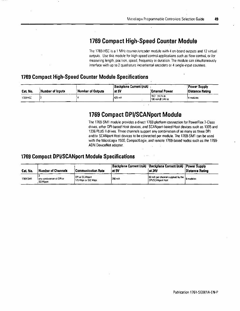
MicroLogix Programmable Controllers Selection Guide 49
1769 Compact High-Speed Counter ModuleThe 1769-HSC is a 1 MH2 counter/encoder module with 4 on-board outputs and 12 virtualoutputs. Use this module for high-speed control applications such as flow control, or formeasuring length, position, speed, frequency or duration. The module can simultaneouslyinterface with up to 2 quadrature incremental encoders or 4 single-input counters.
1769 Compact High-Speed Counter Module Specifications
Backplane Current (mA) Power SupplyCat No. Number of Inputs Number of Outputs at 5V Extemal Power Distance Ratng
17659HSC 2 4 425 mA 19 2 31 2V dc 4 modules
1769 Compact DPI/SCANport ModuleThe 1769-SM1 module provides a direct 1769 platform connection for PowerFlex 7-Classdrives, other DPI-based Host devices, and SCANport-based Host devices such as 1305 and1336 PLUS II drives. Three channels support any combination of as many as three DPIand/or SCANport Host devices to be cdnnected per module. The 1769-SM1 can be usedwith the MicroLogix 1500, CompactLogix. and remote 1769-based nodes such as the 1769-ADN DeviceNet adapter.
1769 Compact DPI/SCANport Module Specifications
Publication 1761-SGOO1A-EN-P

50 MicroLogix Programmable Controllers Selection Guide
1769 Compact DeviceNet Scanner and DeviceNetAdapter Communications ModulesVia the 1769-SDN, a MicroLogix 1500 controller can act as a DeviceNet master, slave orpeer. The 1769-SDN provides standard DeviceNet master functionality, as well as severalnew performance and ease-ol-use features. With the 1764-LRP processor, you can alsomessage between devices using one of two methods fPCCC and Explicit messaging) andperform program upload, download and monitoring through the scanner.
The 1769-ADN is a DeviceNet adapter/slave module that supports the DeviceNet 2.0Specification. The adapter allows any, 1769 Compact discrete, analog or specialty I/Omodule to become part of a DeviceNet system.
Both modules can be configured using RSN~etWorx for DeviceNet software.
1769 Compact DeviceNet Modules Specifications
PowerCommunication Power Requirements, Consumption BW) ackplane Current Power Supply
Cat. No. Rate Cable Max at 24V (mA) at 5V Distance Rating
1769-SDN scanner * 125Kbps ANlen-Bradley pan number mAXllVde 2.2 , , OmA 4 modules
1769ADN adapter 500 Kbps F 90 12.5 450 mA 4 modules
Publication 1761-SG001A-EN-P

MicroLogix Programmable Controllers Selection Guide 51
:-.
... .. - :
1769 Compact Power Supplies, Expansion Cablesand End CapsUsing an expansion 1/0 power supply increases the system's capacity lor adding expansion1/0 modules.
1769 Compact Power Supplies Specifications
Specification 1769-PA2 1769-PB2 |1769-PA4 1769-PB4Nominal Input Voltage 12DVac or 240Va 24V di 120V ac or 240V ac 24Vdc
Input Voltage Range 85 265V ac 19 2 31 .2V dc 85 .265V ac 19.2 32V dc
Maximum Line Requirement 100 VA @ 120V ac 50 VA @ 24V di 200 VA @ 120V ac 100 VA @ 24V dc130 VA @ 240V ac 240 VA@0240V ac
2 A@05V dc 4 A@05VdcOutout Bus Curient Capacity (O to 55'CI 08 A 24V dc 2 A @ 24V dc
24V dc User Power Capacity 1O0 to 55'C) 250 mA - -
25 A I 132V ac. 100 nsource 25 A @ 132V ac 10 source
Maximum Inrush impedance 3Osorc 3A C31.2V Ec impedance 30 AO031.2V rtc40 A 265V x IO n source 30A lV40 A @ 265V ac. 10 Q sourceimpedance impedance
Line Loss Ride Through 10 ms (minimum).. 10 s (maximum) 5 ms Iminimum) . 10 s Imaximum)
Minimum Load Current 0 mA C 5V dc. 0 mA C 24V dc
Front Access Fuse (replacement Front Access Fuse (replacement Front Access Fuse (replacement Front Access Fuse (replacement
Shno Circuit Protection panjn n 13 194A part number Wickmann 19193- par number Wickmann 19185- pan number. Wickmann 19193-3 15A. Wickmann 19343-1 6A. 3A .5oricmm118-A 63Aor Wickmann 19181.4A) 63)31Ao ilmn 98-A .A
Bus Overvoltage Protection for both 45V dc and for +24V dc
1836Vacfor 1 s or 2596Vdc 1200Vac lorI s or 1697Vdc 1836Vac for1 sor 2596Vdc 1200Vacfor 1 s or 1697VdcIsolation Voltage for 1 s for 1 s for1 s tor 1 sinput power to 1769 bus) or or or or
Verified by one of these dielectric tests 265V Working Voltage IlEC 75V Working Voltage IIEC Class 265V Working Vohage IIEC 75V Working Voltage IIEC ClassClass 1 -grounding required) 1 - grounding required) Class 1 - grounding required) 1 grounding required)
Power Supply Distance Rating e luP to eight l/O modules can be connected on either side of the power supply tor a maximum of 16 modules)
Cenaficatioru: UL SF. CSA IC0ass 1. Dvison 2. Gioup A. .C. Dl. CE
Publication 1761-SGOO1A-EN-P

; 52 MicroLogix Programmable Controllers Selection Guide
I .
Expansion cables are required when adding a second bank of I/O modules. They areconnected from the right side of the controller bank to either the left or right side of theexpansion bank.
1769 Compact. Expansion Cables Selection ChartA_
Cable Type , Length Cat No.righi bank-o-right bank 305 mm Ii) 1769tRR1
right bank-to-right bank 1 m 13.28 t) 1769-CRR3
righi bank-to-leht bank 305 mm i1 fil 1769-CRL1
right bank-to-left bank I m 13 28 h) . 1769-CRL3
In every expansion V/O system, an end cap must be used to terminate the end of the serialcommunication bus. The end cap is connected to the last I/O module in the system.
1769 Compact End Caps Selection Chart
End Cap Cat No.right end cap 1769-ECR
lett end cap 1769-ECL
Publication 1761-SGOO1A-EN-P
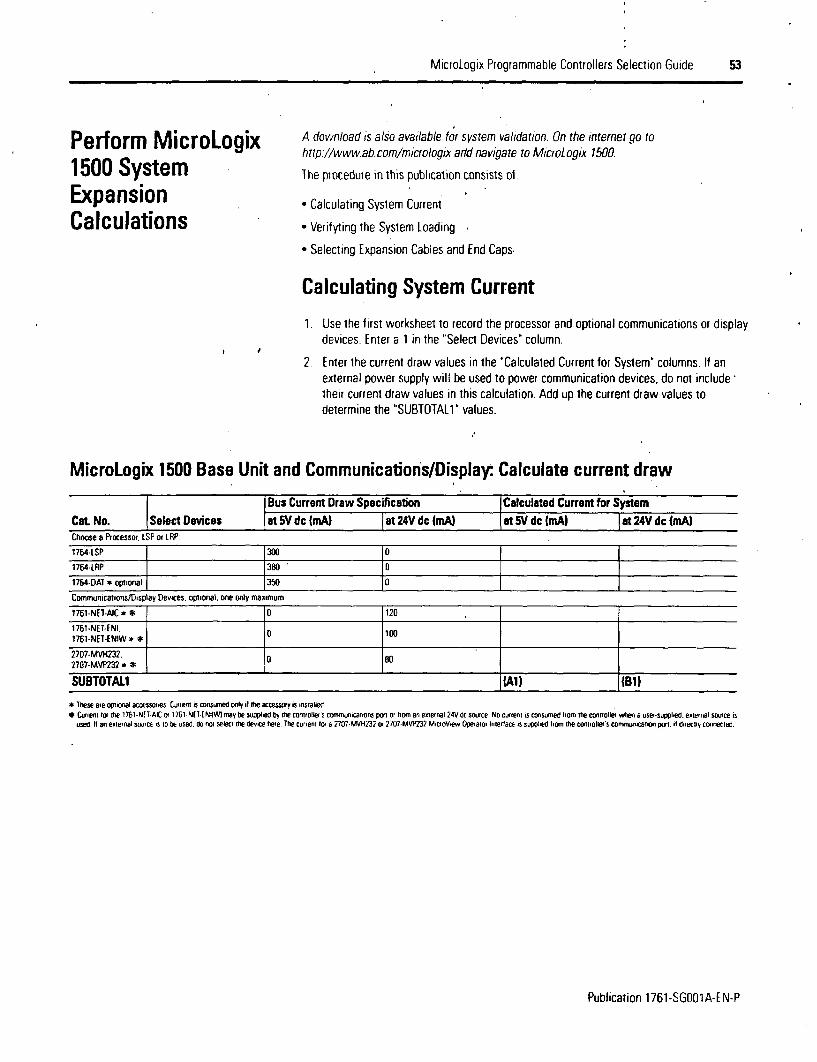
MicroLogix Programmable Controllers Selection Guide 53
Perform MicroLogix1500 SystemExpansionCalculations
A download is also available for system validation. On the internet go tohttp.//www.ab.com/micrologix ard navigate to MicroLogix 1500.
The procedure in this publication consists of:
* Calculating System Current
* Verifyting the System Loading
* Selecting Expansion Cables and End Caps
Calculating System Current
1. Use the first worksheet to record the processor and optional communications or displaydevices. Enter a 1 in the "Select Devices" column.
2. Enter the current draw values in the 'Calculated Current for System" columns. If anexternal power supply will be used to power communication devices, do not include,their current draw values in this calculation. Add up the current draw values todetermine the 'SUBTOTALl" values.
MicroLogix 1500 Base Unit and Communications/Display: Calculate current draw
Bus Current Draw Specification Calculated Current for SystemCat. No. Select Devices at 5V dc ImA) Fat 24V dc ImA) at5VdcImAl |Iat24Vdc(mA)Choose a Processor. LSP of LRP
1764-ISP 300 0
1764-LRP 380 I
1764-DAI * optional 350 0
Communicalions/Display Devices, optional, one only maximum
1761-NET-AIC * 0 120
1761 -NET-ENI. 0 1001761-NEI-ENIW * 0
2707-MvH232 02707-MVP232 0 80
SUBTOTALI IA_ _ _ _ _ _
* These are optional accessories Current 4 consimned only ift e accessory is installed
* Curiern tor the 176t-N[7 AICor 1761-NET-ENiI may be supplied by the conrollers cornnunications port or horn an exernal 24Vdc source No current is consumed iorn the controller wena user-suppled. elteinal source isused if an external source s to bE used go not select the device here The current to a 707MPVH237 or 7707-MVP232 MrtoVew Operator intertace is suppled ttom the controlles cornrurcaton port. it driectiV conneCled.
Publication 1761-SGOO1A-EN-P
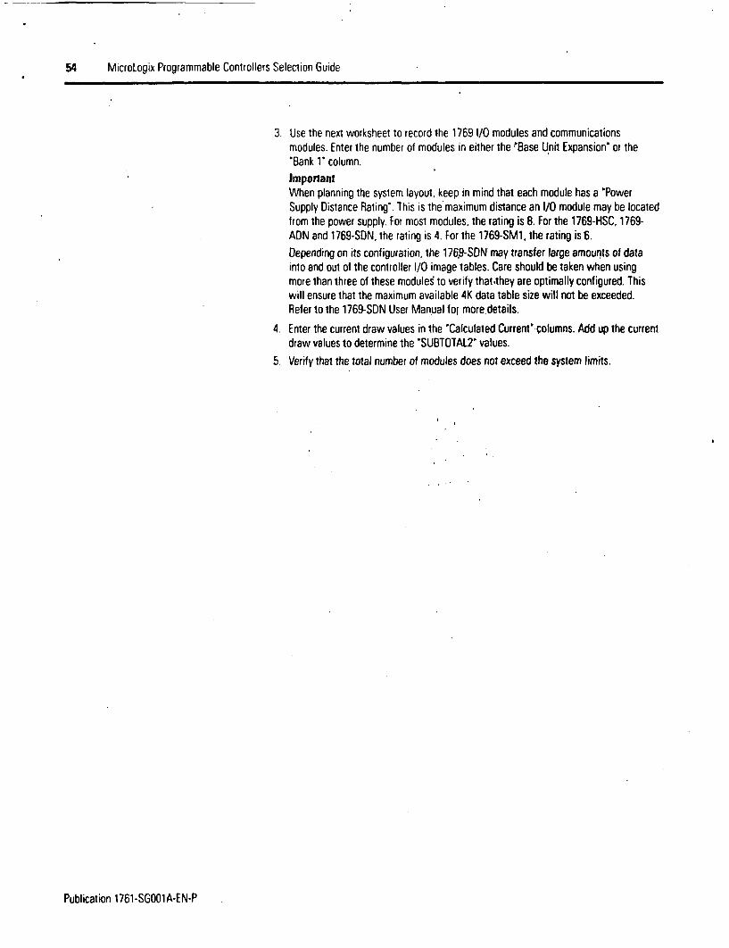
54 MicroLogix Programmable Controllers Selection Guide
3. Use the next worksheet lo record the 1769 I/O modules and communicationsmodules. Enter the number of modules in either the ABase Unit Expansion' or the'Bank 1' column.ImportantWhen planning the system layout, keep in mind that each module has a 'PowerSupply Distance Rating-. This is the maximum distance an I/O module may be locatedfrom the power supply. For most modules, the rating is 8. For the 1769-HSC, 1769-ADN and 1769-SDN, the rating is 4. For the 1769-SM1, the rating is 6.
Depending on its configuration, the 176,9-SDN may transfer large amounts of datainto and out of the controller I/O image tables. Care should be taken when usingmore than three of these modules to verify that they are optimally configured. Thiswill ensure that the maximum available 4K data table size will not be exceeded.Refer to the 1769-SDN User Manual for more~details.
4. Enter the current draw values in the 'Calculated Current' columns. Add up the currentdraw values to determine the 'SUBTOTAL2' values.
5. Verify that the total number of modules does not exceed the system limits.
Publication 1761-SGO01A-EN-P
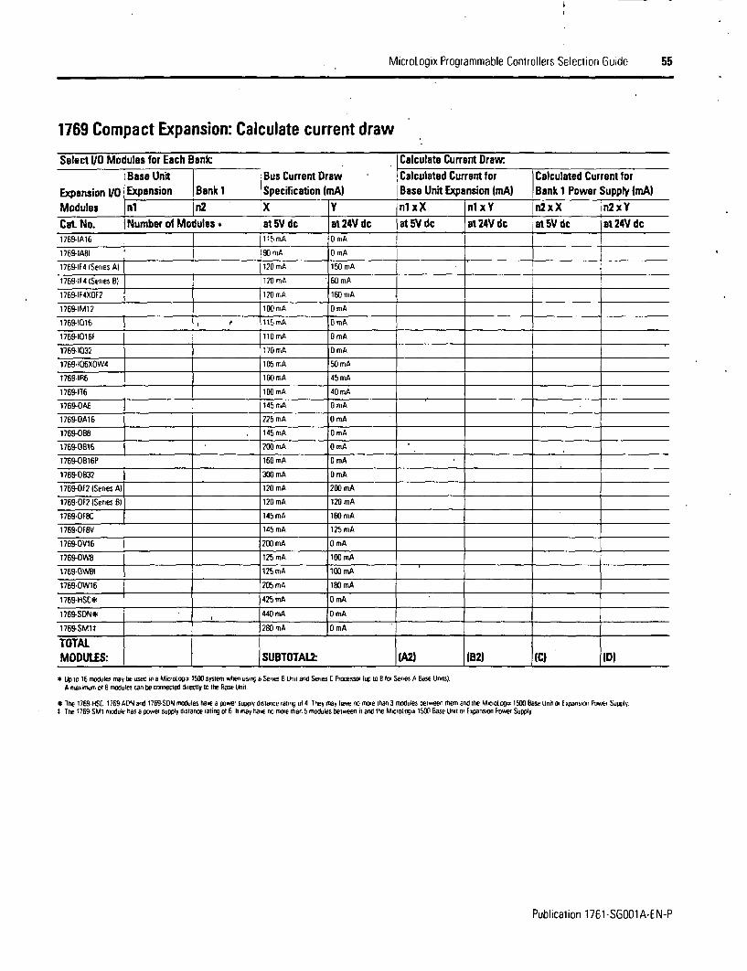
MicroLogix Programmable Controllers Selection Guide 55
1769 Compact Expansion: Calculate current draw
Select V/0 Modules for Each Bank:c Calculate Current DrawI Base Unit Bus Current Draw Calculated Current for Calculated Current for
Expansion V1 Expansion Bank 1 ,Specification IrnAI Bass Unit Expansion ImA) Bank 1 Power Supply (mA)Modules nl jbn2 X Y 'nl x |nI xY n2xX n2xYCat No. Number of Modules* at 5V dc at 24V dc at 5V dc at 24V dc 1 at 5V dc jat 24 dc1769-IA16 115mA OmA
1769-IA81 90 mA 0 mA
1769-IF4 (Series Al 120 mA 150 mA
1769-4F4 (Series B) 120 mA 60 mA I
1769-IF4XOF2 1_20 mrnA 160 mA
1769-IM12 To mA D mA
1769-1016 .0 1115mA OmA1769-1016F l10mA 0 mA
1769-1032 170 mA DmA
1769-106XOW4 105 mA 50 mA
1769-I1R6 100 mA 45 mA
1769-176 100 mA 40 mA
1769-OA8 145 mA 0 mA
1769-OA16 225 mA OmA
1769-08_ 145 mA 0 mA
1769-OB16 200 mA 0 mA
1769-OB16P_ 160 mA 0 mA
1769-OB32 300 mA 0 mA
1769-OF2 ISeries A) 120 mA 200 mA
1769-OF2 ISeries B) 120 mA 120 mA
1769-OFBC 145 mA 160 mA
1769-OF8V 145 mA 125 mA
1769-OV16 200 mA 0 mA
1769-OW8 125 mA 100 mA
1769-OWBI 125 mA 100 mA
1769-0W16 205 mA lB0 mA
1769-HSC* 425 mA 0 mA
1769-SDNt, 440 mA O mA
1769-SM1b 280 mA D0mATOTALMODULES: ISUBTOTAL2 IA2) (B2) CC) (D
* Up IC 16 modules mav be used in a Miciotogi, 1500 system when usig a Series E Unt and Series C Processor (up ro EB fi Series A Base Unilsl.A maximum ot F modules can be connected directly to the Base Unit
* Tre 1769%HSC. 1769-ADN and 1769 SDN modules havea power supply distance rating ol4 They may hnave no mome than3 mtodules between tmem and the MiCrologia 1500 Base Unit or Expansion Power Supply.1 The 1769 SM1 mnoule has a power supply distance rating of 6 h1 may hnave no more than 5 modules between it and the Microtoni 1500 base Unit or Bxpansion Power Supply.
Publication 1761-SGOO1A-EN-P

56 Micrologix Programmable Controllers Selection Guide
Verifying the System LoadingTo have a valid system, both current and power requirements must be satisfied.
Verifying the Base Unit Loading1. Enter the SUBTOTAL values from the worksheet, MicroLogix 1500 Base Unit and
Communications/Display Device: Calculate current draw, and 1769 CompactExpansion: Calculate current draw. Add the total current draw for the Base Unit.Verify the values are within the maximum limits.
MicroLogix 1500 Base Unit Power Supply Loading: Verify that current values are within limrts
Calculated Current for SystemCurrent from: at 5V dc OmA) at 24V dc (mAIFor 1 764-24BWA only, enter sum of any User 24V dc Sensor Curren In
MAXIMUM LIMI1 400 mA User 24V dc
Values from SUBIOTAL1 (All IBll
Values from SUBTOTAL2 (A2) ZE2)
TOTAL BASE UNIT CURRENT LOADING IF) IG)
MAXIMUM UMIT 2250 mA at SV dc 400 rA at 24V dc
2. Using the table below, verify that the MAXIMUM POWER LIMIT is not exceeded.
MicroLogix 1500 Base Unit Power Supply Loading: Verify that power value is within limbts
Cat No * 1764-24AWA, 1764-28BXB 1764-24BWA5V Power Calculation IF) x SV . W IF) x SV W
24V Power Calculation IG) x 24V * W (GI x 24V * W
(E) s 24V W
Add up Total Watts W W
MAXIMUM POWER LIMIT 16W , 22 W
Publication 1761-SGOO1A-EN-P

MicroLogix Programmable Controllers Selection Guide 57
Verifying the Expansion Power Supply Loading
Using the values from SUBOTAL2, verify that the system loading and I/0 distribution arewithin the limits shown in the worksheet, Bank 1 Power Supply Loading: Verify thatcurrent values are within limits. Consider future expansion when selecting a power supply
Bank 1 Power Supply Loading: Verify that current values are within limits
Calculated Current for System 124V dc UserSpecificCat. No. at 5V dc imAi| jat 24V dc (mA) Output Capacity-Values fhom SUBTOTAL? on page 55 IC) ID)
1769-PA2 2000 - 00 250 mA
1769-PA4 4000 2000
MAXIMUM CURRENT LIMIT 179P20080
1769-P'B4 4000 2000
1769-PA2 2000 800 250 mA
1/0 Oistribution - Distribute I/O modules such that the current consumed from either 176PA4 2000 il00the left side or the right side of the power supply never exceeds the following values 1769-PB2 2000 BO
1769-PS4 201010 0 _
Selecting Expansion Cables and End CapsAny system using Compact l/0 must have an end cap. If I/O Bank 1 is used, an expansioncable is also required. If you have not already done so, make your selection from the tablebelow
Select End Cap and Expansion Cable
Type of System Requirement Cat No. SelectedBase Unrt with Compact 1/0 only right end cap 1769-ECR
right-to-left expsansion cable 1769-cHt. 1769-cRL3Base Unt with Compact 1/O and Bank 1, horizontal orientation right end cap 176CR
right end cap 1769-ECRright-to-right expansion cable 1769-cRR1l 1769-CRRL3
Base Unit with Compact I/O and Bank 1, verticalorientation le rt end cap 1769-C 1left end cap 1769-ECL
Publication 1761-SG001A-EN-P

58 MicroLogix Programmable Controllers Selection Guide
Step 10 - Select
* replacement parts - AIC- and DNIreplacement terminal blocks are listedwith the MicroLogix 1000
Select Replacement Parts
* record your selections in the SelectionRecord (starts on page 60)
MicroLogix 1000 Replacement Parts
Cat No. Descfiptiont761-RPL-732X Terminal Cover Doors for 1761-L32AAA. -L32AWA, -LS2BWA. -LS3BWB. or -L32BBB i2 doors per package)
1761-RPL-OIN Replacement DIN Rail Latches for MicroLogix 100 Controllers 12 per package)
1761-R130 Replacement Terminal Block tor 1761-NEI-AIC. 6-position DH-485 plug/cornector
1761-RPL.RlOO Replacement Terminal Block for 1761 -NEI-DNI. 5-position DeviceNet plug/connector
MicroLogix 1200 Replacement Parts
Cat. No. Description1762-RPLRTB40 Replacement Terminal Block for t762-L40AWA and -L40BWA
1762-RPLDIN2 Replacement DIN Rail Latches for 1762 1/0 Modules
1762-RPLDR2 Replacement Door Kit for 1762 110 Modules 12 1/0 module doors. 2 communications bus doorsl
1762-RPLTLBU2 Replacement Terminal Label Ki for 1762 l/0 Modules
MicroLogix 1500 Replacement Parts
Cat No. Descrip0on1764-RPLTB1 17-Point Replacement Terminal Block for 1764-24AWA and 1764-24BWA MicroLogix 1500 Base Units
1764-RPLTB2 21-Point Replacement Terminal Block for 1764-2BBXB MicroLogix 1500 Base Unit
1747-BA Lithuim Batter Ifor RAM Memory Retentionl
Publication 1761-SG001A-EN-P

I
MicroLogix Programmable Controllers Selection Guide 59
Step 11 - Select:
* training and promotional products -starter paks. demo units and simulators
- record your selection in the SelectionRecord (starts on page 60)
Select Training andPromotional Products
Training and Promotional Products for MicroLogix 1000, 1200 and 1500
Description Cat No.MicroMentor Basics Book Provides an introduction to understanding and applying PlC iundamentals 1761-MME
Micrologix 1000 RSLogix Starter Pal includes 1761-116BWA controller. 9324-RlOlODENE (IRSIogi, Starter Programming Software). 1761-CBL-PM02 PC-to- 1761 ll BWA R1Econtroller cable. 1761-SIM-6t6 input switch simulator. user documenrarion
MicroLogis 1000 10-Point Controller Starter Pak includps 1761-116BWA comroller. RSLogix 500 Starter Software for 10-Point MicroLogra Controllers. RSLmn Lile. 1761-SIARllOOOE1761-CBE-PM02 PC-to-controller cable, user documentation
MicroLogix 1200 FISLogix Staner Pak includes 1762-L24BWA contoller. 9324-RIO[OOENE IRSLogix Starter Programming Software). 1761-CBl-PMO2 PC-to- 1762-SlAR 1 R12controller cable. 1796-SIM1200 input switch simulator, user documentation
MicroLogis 1500 l Siogix Starter Pak includes 1764-LSP processor, 1764-24BWA base unit. 9324-RLD100ENE (IRSlogix Starter Programming Software). 1764-CBL- 1PMO2 PC-to-contoller cable, 1796-SIM1500 input switch simulator, 1764-MMIfiC memory module and real-time clock; user documentation 1764-S1ARIlSOOE
Micrologix 1500 RSLogix Starter Pak includes: 1764-LRP processor. 1764-24BWA base unit. 9324-RL0100ENE IRSLogix Starter Programming Software]. 1764-CBL-PMO2 PC-to-controller cable. 17.i-SIM1500 input switch simulator. 1764-MMIR1C memory module and real-time clock. user documentation 1764-SIARllSOORE
MicroLogix 1000 Integrated Demonstration Unit includes 1761-U2OBWA-5A controller, 1761-NE1-AIC OH-485 Interface, 1761-NE1-DNI DevriceNet Interface,quadrature encoder, 4 selector switches. 8 illuminated pushbuntons; 1 potentiometer. 1 analog meter . 1796-MICRD1
MicroLogix 1500 Integrated Demonsnration Unit includes 1764-28BXB base unit: 1764-LSP processor unit. 17694IF4 Analog Input Module. 1769-OF2 Analog Output 17Module;1761-NEI-AIC DH-485 Interface Module. 1761-NET-DNI DeviceNet Interlace Module. quadrature encoddr; 4 selector switches; 8 illuminated pushbuttons. 196-MICRi1511 potentiometer; 1 analog meter. 1 trequency meter (Series Bl
MicroLogix 1000 Input Simulator For use with 1761-L16BWA MicroLogis 1000 Programmable Controller. 1761-SIM-B16
MicroLogix 1200 Input Simulator. For use with 1762-L24BWA and 1762-L24BXB controllers 1761-SIM1200
MicroLogix 1500 Input Simulator For use with 1764-24BWA and 1764-268XB base units 1796-SlM1500
MicroLogixl 200/PanelView300 Micro IntegratedOemonstration Unitincludes 1762-L24BWA. 2711-M3A18L1. inductiveproximityswitch photo-electic sensor 1796-PV300MICROlprogramirrng cable.
Publication 1761-SGOO1A-EN-P
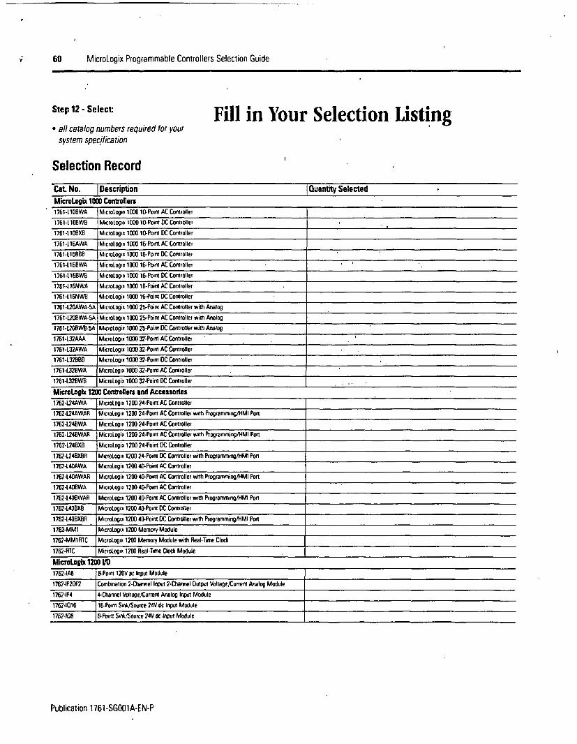
60 MicroLogix Programmable Controllers Selection Guide
Step 12- Select: Fill in Your Selection Listing* all catalog numbers required for your
system specification
Selection Record
Cat No. I Description lQuantity Selected
MicroLopix 1000 Controllers1761-11DBWA MicroLogix 1000 10-Point AC Controller
1761-LlOBWB MicioLogix 1000 10-Point DC Controller
1761-Ll0XB MicroLogix 1000 10-Ponm DC Controller
1761-116AWA MicroLogin 1000 16-Po'int AC Controller
1761-L16BBB MicroLogix 1000 16-Pont DC Controller
1761-L16BWA MicloLopin 10W 16-Point AC Controller
1761-l16BWB MicroLogin 1000 16-Point DC Controllet
1761-116NWA MicroLogx 1000 16-Point AC Corntoller
1761-L16NWB MicroLogii 1000 16-Point DC Controller
1761-U4OAWA-SA MicroLogix 1000 25-Point AC Controller with Analog
1761-L208WA-SA MicroLogix 1000 25-Point AC Controller with Analog
1761-L208WB-SA Microtogix 1000 25-Point DC Controller with Analog
1761 -U32AAA MicroLogix 1000 37-Point AC Controller
1761-.32AWA MicroLogix 1000 32-Point AC Controller
1761-L32880 MicroLogix 1000 32-Point DC Controller
1761-L32BWA MicroLogix 1000 32-Point AC Controller
1761-L32BWB MicroLogix 1000 32-Point DC Controller . .
UicraLongx 1200 Controllers end Accessories1762-124AWA MicroLogix 1200 24-Poim AC Controller
1762-U24AWAR MIcroLogin 1200 24-Point AC Controller with Programming/HMl Ponr
1762-U24BWA MicroLogin 1200 24-Point AC Controller
1762-1244BWAR MicroLogin 1200 24-Point AC Controller with Programming/HMI Port
1762-124BXB MicroLogix 1200 24-Point DC Controller
1762-L24BXBR MicroLogix 1200 24-Point DC Controller with Programming/lMI Pon
1762-L40AWA MicroLogix 1200 40-Point AC Controller
1762-t40AWAR MicroLogix 1200 40-Poim AC Controller with Programming/HMI Ponr
1762-LU4BWA MicroLogix 1200 40-Poimt AC Controller
1762-440BWAR MicroLogix 1200 40-Point AC Controller with Programming/HMI Port
1762-L408XB MicroLogix 1200 40-Point DC Controller
1762-L40BXBR MicroLogix 1200 40-Point DC Controller with Programming/HMI Port
1762-MM1 MicroLogix 1200 Memory Module
1762-MMlRIC Micrologi 1200 Memory Module with Real-Time Clock
1762-RTC MicroLogix 1200 Real-Time Cock Module
MicroLogix 1200 UO
1762-lA8 B-Point 120V ac hnput Module
1762-lf20r2 Combnation 2-Channel Input 2-Channel Output Voltage/Current Analog Module
1762-IF4 4-Channel Voltage/Current Analog Input Module
17624016 16-Point Sink/Source 24V dc Input Module
1762-108 8-Poirn Sink/Source 24V dc Input Module
Publication 1761-SGOO1A-EN-P
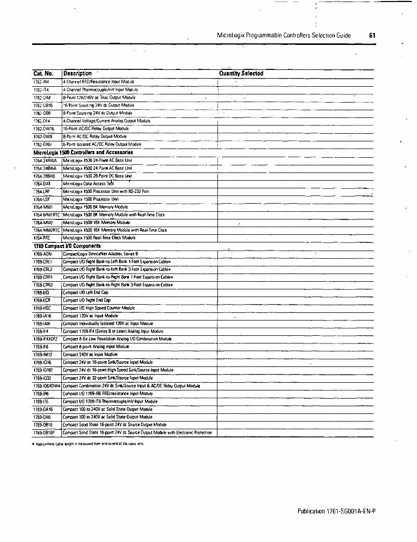
MicroLogix Programmable Controllers Selection Guide 61
Cat No. Description Quanfity Selected1762-lR4 4-Channel RFD/Resistance Input Module
1762-114 14-Channel Ihermocouple/mV Input Module
1762-OA8 4-hPonnl 120h4DV ac Triac OuIput Module
1762-0B16 16-Point Sourcing 24V dc Output Module
1762-OBE 8-Point Sourcing 24V dc Output Module
1762-DF4 4-Channel Voltage/CUofent Analog Output Module
1762-OW16 16-Point AC/DC Relay Output Module
1762-OW8 8-Point AC/DC Relay Output Module
1762-OX61 6-Point Isolated AC/DC Relay Output Module
MicroLcgqtx 1500 Controllers and Accessories1764-24AWA MicroLogix 1500 24-Point AC Base Unit
1764-24BWA MicroLogil 1500 24-Point AC Base Unit
1764-28BXB Miclotogie 1500 28-Point DC Base Unit
1764-DAI Micrologix Data Access lobl
1764-LRP MicroLogix 1500 Processor Unit with RS-232 Pon
1764-LSP MicrOLogix 1500 Processor Unit
1764-MM1 Micrologri 1500 8K Memory Module
1764-MMlRTC MicroLogix 1500 BK Memory Module with Real-Time Clock
1764-MM2 MicroLogix 1500 16K Memory Module
1764-MM2RIC MicroLogil 1500 16K Memory Module with Real-Time Clock
1764-RTC MicioLogix 1500 Real-Time Clock Module
1769 Compact VO Components1769-ADN CompactLogix DeviceNel Adapter. Series B
1769-CRL1 Compact l/O Right Bank-lo-Left Bank 1-Foot Expansion Cable*
1769-CRL3 Compact l/O Right Bank-to-Left Bank 3-Fool Expansion Cable*
1769-CRR1 Compact I/O Right Bank-to-Right Bank 1-Foot Expansion Cable*
1769-CRR3 Compact I/O Right Bank-to-Right Bank 3-Foot Expansion Cable*
1769-ECL Compact I/O Lell End Cap
1769-ECR Compact I/O Right End Cap
1769-HSC Compact I/O High Speed Counter Module
1769-lA16 Compact 120Vac Input Module
1769-IA8I Compact Individually Isolated 120V ac Input Module
1769-IF4 Compact 1769-lF4 (Series B or Later) Analog Input Module
1769-If4XOF2 Compact 8-Bit Low Resolution Analog I/O Combmnation Module
1769-IF8 Compact 8-point Analog Input Module
1769-IM12 Compact 240V ac Input Module
1769-1016 Compact 24V dc 16-point Sink/Source Input Module
1769-1016F Compact 24V dc 16-point High Speed Sink/Source Input Module
1769-1032 Compact 24V dc 32-point Sink/Source Inpul Module
1769-106XDW4 Compact Combination 24V dc Sink/Source Input & AC/DC Relay Output Module
1769-lR6 Compact 1/ 1769-1R6 RTD/resistance Input Module
1769-176 Compact I/O 1769-176 Thermocouple/mV Input Module
1769-OA16 Compact 100 to 240V ac Solid State Output Module
1769-OAB Compact 100 to 240V ac Solid State Output Module
1769-OB16 Compact Solid Slate 16-point 24V dc Source Output Module
1769-OB16P Compact Solid Slate 16-point 24V dc Source Output Module with Electronic Protection
* Aiqsrmetle te erb S 91hs rriasuied iliro end-to-d et tie a* e WNl
Publication 1761-SGOrlA-EN-P
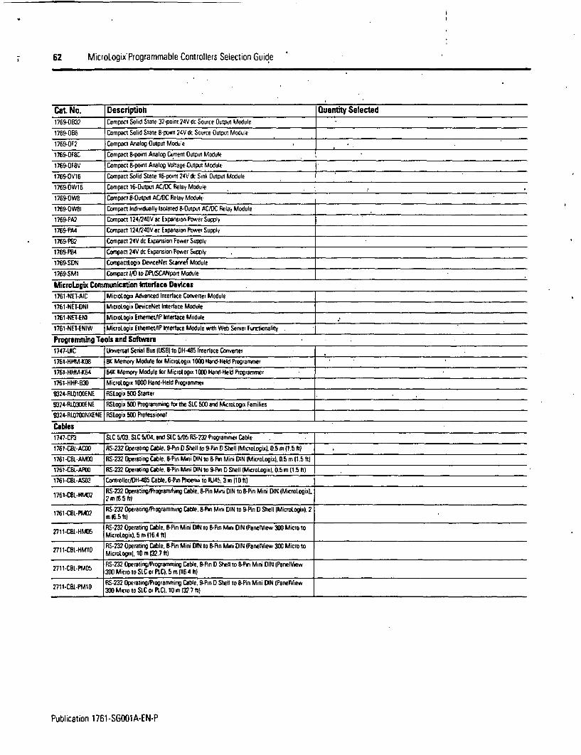
62 MicroLogix Programmable Controllers Selection Guide
Cat No. Descriptioh Quantity Selected1769-0B32 Compact Solid Stale 32-point 24V dc Source Outpin Module
1769-OBEi Compact Solid State B-point 24V dc Source Output Module
1769-OF2 Compact Analog Output Module
1769-OF8C Compact B-point Analog Current Output Module
1769-OF8V Compact 8-point Analog Voltage Output Module
1769-OV16 Compact Solid State 16-point 24V dc Sink Output Module
1769-OW1 Compact 16-Output AC/D)C Rlelay Module
1769-OW1 Compact B-Output AC/DC Relay Module
1769-OWBI Compact Individually Isolated 8-Outpui AC/DC Relay Module
1769-PA2 Compact 124240V ac Expansion Power Supply
1769-PA4 Compact 124/240V ac Expansion Power Supply
1769-P92 Compact 24V dc Expansion Power Supply
1769-PB4 Compact 24V dc Expansion Power Supply
1769-SDN CompactLogix DeviceNet Scannef Module
1769-SMI Compact I/O to DPI/SCANport Module
MicroLogh Communicution Interface Devices1761-NEI-AIC MicroLogix Advanced Interlace Convener Module
1761-NET-DNI MicroLogix DeviceNet Interlace Module
1761-NET-ENI MicroLogix Ethemet/lP Interlace Module
1761-NE1-ENIW MicroLogix Ethemet/lP Interface Module with Web Server Functionality _
Programnning Tools and Software1747-UIC Universal Serial Bus (USBI to OH485 Interface Convener
1761 -HHM-KO8 BK Memory Module for MicroLogix 1000 Hand-Held Programmer
1761-HHM-K64 64K Memory Module for Micrologix 1000 Hand-Held Programmer
1761-HHP-830 MicroLogix 1000 Hand-Held Programmer
9324-RL0100ENE RSLogix 500 Starter
9324-RLO300ENE RSLogix 500 Programming for the SLC 500 and MicioLogix Families
9324-RU0700NXENE RSLogix 500 Professional
Cables1747-CP3 SLC 5/03. SIC 5/04, end SLC S/05 RS-232 Programmer Cable
1761 CBL-ACOO RS-232 Operating Cable. 9-Pin D Shell to 9-Pin D Shell IMicrotogiul, 0.5 m 11.5 It
1761-CBL-AM00 RS-232 Operating Cable. 8-Pin Mini DIN to B-Pim Mini DIN IMicroLogix). 0.5 m 11.5 II)
1761-CBL-APOO RS-232 Operating Cable. 8-Pin Mini DIN to 9-Pin D Shell (MicroLogixl. 0.5 m (1.5 hI)
1761-CBL-AS03 Conrtoller/DH-485 Cable. 6-Pin Phoenix to RJ45. 3 m 11 Ot)
1761-CBL-HM02 RS-232 Operating/Programrning Cable. B-Pin Mini DIN to B-Pin Mini DIN (Micrologix).1761-BL-H,402 2 mr 16.5 III
1761SL-PMI2 RFS-232 Operating/Programming Cable. -Pin Mini DIN to 9-Pin D Shell IMicrodogixi. 21761-M-PW in 16.5 It)11-CBL-HM v10RS-232 Operating Cable. 8-Pin Mini DIN to B-Pin Miii DIN IPanelView 300 Micro to
2711 *IH 5 MicroLogix). S m 116.4 Ilt
2711-CBLHM10 RS-232 Operating Cable. B-Pin Mini DIN to B-Pin Mini DIN IPanelView 300 Micro to-L MicroLogix). 10 m (32.7 ft)
L RS-232 Operating/Programming Cable. 9-Pin D Shell to B-Pin Mini DIN (PaneltView2711t-CBL-PM05 300 Micro to SLC or PLC. 5 m 1164 hJ)
RS-232 Operating/Programming Cable. 9-Pin D Shell to B-Pin Mini DIN (PanelView2711-CBL-PM1O 300 Micro to SLC or PLC). 10 m (32.7 It)
Publication 1761-SG001A-EN-P

MicroLogix Programmable Controllers Selection Guide 63
Cat No. Description Oluantty SelectedStarter Paks1761 -16BWA- R1E MicroLoqp 1000 RStogix 500 Staner Pal
1761-S5AR71000E MicroLogj) lDOO' 10-Point Controller Starter Pak
1762-STAR11200E Micro[ogix 1200 RSI. o 500 Starter Pak
1764-SARl1500E MicroLogix 1500 1764-LSF ASLogix 500 Starter Pak
1764-SAR1150ORE MicroLogix 1500 1764-LRP RS[oogx 500 Starter Pak
Demonstration Units and Simulators1761-MMB MicroMentor Basics Book
1761-SIM-B1b MictoLogro 1000 Input Simulator
1796-MIRCROl MicroLogix 1000 Integrated Demonstration Unrt
1796-MICROl15 MicroLogix 1500 Integrated Demonstration Unit
1796-PV300MICRO1 Micrologix 1200/PanelView 300 Micro Integrated Demonstration Unrt
1796-SIM12W0 MicroLogix 1200 Input Simulator
1796-SIM1S00 MicroLogio 1500 Input Simulator
MicroView Units2707-MVH232 MicroView Handheld. 2 Line LCD. RS-232. 11 25V dc. Class 1 DOv 2 Rated
7707-MVP732 MicroView Panel Mount. 2 Line LCD. RS-232. 11 25V dc Class 1 DO v 2 Rated
Replacement Parts1747-BA Lithuim Battery (For RAM Memory Retention)
1761-RPL-DIN Replacement DIN Rail Latches for MrcroLogix 1000 Controllers (2 per package)
1761-RPL-R1TW Replacement lerminal Block for 1761-NE1-ONI, 5-position DeviceNei plug/connector
lerminal Cover Doors for 1761-L32AAA. -L32AWA. -L32BWA. -L32BWB. or -L32BBB1761-RPI-T32X (2 doors per package)
1762-RPLDIN2 Replacement DIN Rail Latches (or 1762 I/O Modules
1762-RPLDR2 Replacement Door Kit 1or 1762?1/0 Modules (2 I/O module doors, 2 communications1762-PLOR2 bus doors)
1762-RPLRIB4O Replacement lerminal Bloci lot 1762-L40AWA and -L40BWA
1762-RPLTLBL2 Replacement Termrnal Label Kit nor 1762 1/0 Modules
1764-RPLTBI 17-Point Replacement Terminal Block tor 1764-24AWA and 1764-24BWA MicroLogro1500 Base Units
1764-RPITB2 21-Point Replacement Terminal Block (or 1764-28BXB MicroLogix 1500 Base Uninr
Publicalion 1761-SG001A-EN-P

I
Rockwell Automation SupportRockwell Automation provides technical information on the web to assist you in using our products. Athnp://support.rockwellautomation.com, you can find technical manuals, a knowledge base of FAQs. technical and application notes,sample code and links to software service packs, and a MySuppor feature that you can customize to make the best use of these tools.
For an additional level of technical phone support for installation, configuration and troubleshooting, we offer TechConnect Supportprograms. For more information, contact your local distributor or Rockwell Automation representative, or visithttp://support.rockwellautomation.com.
Installation AssistanceIf you experience a problern with ahardware module within the first 24 hours of installation, please review the information that iscontained in this manual. You can also contact a special Customer Support number for initial help in getting your module up and running.
United States M vonday - Friday. rSam - 5 prn [SI
Outsi*e United States PlFease cnta~ct toul ocul Rockwell Autornation representative frv arr technical support: issues.
New Product Satisfaction ReturnWe test all of our products to ensure that they are fully operational when shipped from the manufacturing facility. However, if yourproduct is not functioning and needs to be returned:
Une trsContrac youi diStributor YOU must provide a CUSIOmner SUPPOrt case nurne Isefe phone nunibet abve t'C obtain one) tO yout distributor in order tO COirrilee the
Outside United States Please coritac YOUr local Rockwell Au anillion representative ror return rprocedure.
Miciroogix, StC nd Sitogix are trademarks of Rockwell Auiomaiona Inc.
wWrackwefll inattiorLCom
Corporate HeadquartornRockwell Autornation, 777 East Wisconsin Avenue, Suite 1400. Milwaukee, WI. 53202-5302 USA. 7el: 1)414.212.5200. Fax: 111414.212.5201
HeadquaIters tor Aien-Uredley Products. Rockwell Software Products end Global Marnafacturing SolutionsAmerices: Rockwell Autornation. 1201 South Second Street. Milwaukee, WI 53204-2496 USA. Tel (1l414.382.2000. Fax 11)414.382.4444Europe: RockwvelrAutomationSA/NV. Voystlaan/boulevard du Souverain36-BP 3A/E. 1170 Brussels. Belgium. lel: (32126630600, Fax: (3212663 0640Asia Pacific: Rockwell Autornation. 27/F Citcorp Centre. 1S Whitfield Road, Causeway Bay. Hong Kong, Tel. 185212887 4768. Fax: 185212508 1646
Headquarters for Dodge and Reliance Electic ProductsArredicas Rockwell Automation. 6040 Ponders Coun. Greenville. SC 296154617 USA. Tel: (1I864.297 4800. Fax: (11 864.2812433Europe: Rockwell Automation. BruhistralE 22, D-74834 Elzial-Dallau. Gernany, Tel: (4916261 9410. Fax (49) 6261 1774Asia Pacific: Rockwell Automration. 55 Neewton Road. #11-01/02 Revenue House. Singapore 307967, Tel (65) 351 6723. Fax: 1651 355 1733
Publication 1761-SG001A-EN-P - AuguE-� 2OG4 Pubicao,176.5001.ErJ.- AguT 204C~'e.' C 5M ~ ft Al "rt --m~ F,,* ,. USA