Construction DewateringConstruction Dewatering aaand …courses/atce2/Lesson7.pdf · ·...
17
TOKYO INSTITUTE OF TECHNOLOGY DEPARTMENT OF CIVIL ENGINEERING ATCE-II ADVANCED TOPICS IN CIVIL ENGINEERING Second Semester 2005 Professor Kamran M. Nemati Temporary Structures Construction Dewatering Construction Dewatering Construction Dewatering Construction Dewatering and nd nd nd Ground Freezing Ground Freezing Ground Freezing Ground Freezing
Transcript of Construction DewateringConstruction Dewatering aaand …courses/atce2/Lesson7.pdf · ·...
TOKYO INSTITUTE OF TECHNOLOGY
DEPARTMENT OF CIVIL ENGINEERING
ATCE-II
ADVANCED TOPICS IN CIVIL ENGINEERING
Second Semester 2005
Professor Kamran M. Nemati
Temporary Structures
Construction DewateringConstruction DewateringConstruction DewateringConstruction Dewatering
aaaand nd nd nd Ground FreezingGround FreezingGround FreezingGround Freezing
ATCE-II
ADVANCED TOPICS IN CIVIL ENGINEERING
Lesson 7: Construction Dewatering and Ground Freezing
Overview
Dewatering means “the separation of water from the soil,” or perhaps “taking the water out of
a particular construction problem completely.” Many excavations are carried below
groundwater level. Techniques for dealing with the problems that result depend on the
excavation dimensions, the soil type, and the groundwater control requirements, among other
factors. The simplest dewatering operations are carried out with little planning. Major
operations in difficult conditions require advanced engineering and construction methods.
Lesson Objectives
By the end of this lesson you will be able to:
• explain the principal dewatering methods available and their applicability to various soil
conditions;
• know which type of dewatering methods are appropriate for various soil conditions;
• recognize some common problems associated with various dewatering methods;
• explain the fundamental requirements for a dewatering system that is reliably designed;
• explain ground freezing.
Reading Assignment
Class notes.
Optional reading: Ratay, Chapter 10 "Construction Dewatering".
ATCE-II – TEMPORARY STRUCTURES LESSON 7: CONSTRUCTION DEWATERING AND GROUND FREEZING
Page 2 of 16
Construction Dewatering
Introduction
The control of groundwater is one of the most common and complicated problems
encountered on a construction site. Construction dewatering can become a costly issue if
overlooked during project planning. In most contracts, dewatering is the responsibility of the
contractor. The contractor selects the dewatering method and is responsible for its design and
operation.
The purpose of construction dewatering is to control the surface and subsurface hydrologic
environment in such a way as to permit the structure to be constructed “in the dry.”
Dewatering means “the separation of water from the soil,” or perhaps “taking the water out of
the particular construction problem completely.” This leads to concepts like pre-drainage of
soil, control of ground water, and even the improvement of physical properties of soil. If
ground water issues are addressed appropriately at the investigation and design stage,
construction dewatering, which involves temporarily lowering the ground water table to
permit excavation and construction within a relatively dry environment, is rarely a problem.
Construction dewatering has existed as a specialty industry for a long time. Consequently, a
number of well-established techniques have been developed to lower the ground water table
during excavation. The geology, ground water conditions, and type of excavation all
influence the selection of dewatering technology. The most common methods for dewatering
include sumps, wells and wellpoints.
• Sumps provide localized, very shallow dewatering (less than 3 feet) and consist of
pumping from perforated drums or casings in a gravel-filled backhoe pit. Sumps work
best in tight, fine grained soils, or very coarse, bouldery deposits.
• Wells are large-diameter (greater than 6 inches) holes, drilled relatively deep (greater than
10 feet), and contain slotted casings and downhole pumps. Wells work best in soils
consisting of sand, or sand and gravel mixtures, and can dewater large areas to great
depths.
• Wellpoints are small-diameter (less than 6 inches), shallow wells, and are closely spaced
(2 to 10 feet apart). Wellpoints effectively dewater coarse sands and gravels, or silts and
clays. They have a wide range of applications. However, wellpoints use a vacuum
system and their depth is limited to about 25 feet. Wellpoint systems generally cost more
than either sumps or wells, and require near-continual maintenance.
A number of other dewatering techniques are available including ground freezing and electro-
osmosis. However, such techniques are very costly and used only for particularly difficult
dewatering applications.
Underwater Excavations In special cases where the soil is very pervious or when it is not possible or desirable to lower
the groundwater table, underwater excavations can be considered. If underwater excavation is
to be performed, the work area must be enclosed with an impervious structure. Once the
impervious structure is in place, the excavation is performed within the structure. Once the
desired excavation level is achieved within the structure, it is sealed with an impervious layer,
such as concrete, in order to prevent water from sipping into the work area. After the
impervious seal has been constructed, the water remaining within the structure is pumped out
and construction is completed.
ATCE-II – TEMPORARY STRUCTURES LESSON 7: CONSTRUCTION DEWATERING AND GROUND FREEZING
Page 3 of 16
Caissons
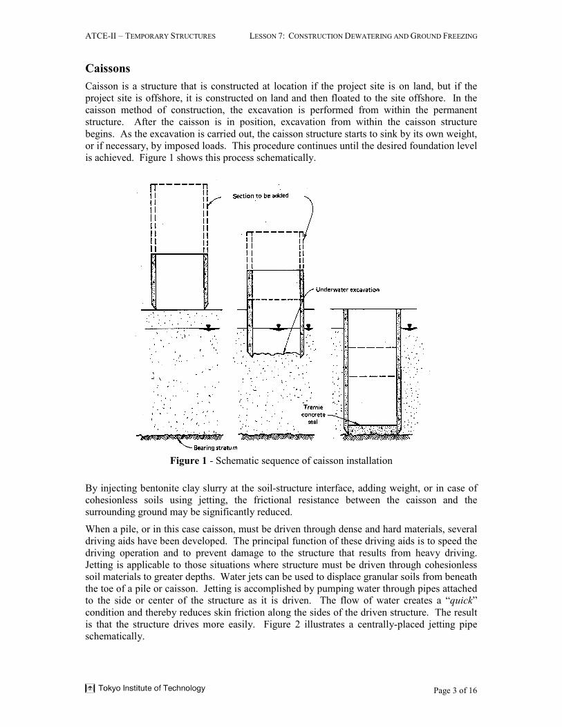
Caisson is a structure that is constructed at location if the project site is on land, but if the
project site is offshore, it is constructed on land and then floated to the site offshore. In the
caisson method of construction, the excavation is performed from within the permanent
structure. After the caisson is in position, excavation from within the caisson structure
begins. As the excavation is carried out, the caisson structure starts to sink by its own weight,
or if necessary, by imposed loads. This procedure continues until the desired foundation level
is achieved. Figure 1 shows this process schematically.
Figure 1 - Schematic sequence of caisson installation
By injecting bentonite clay slurry at the soil-structure interface, adding weight, or in case of
cohesionless soils using jetting, the frictional resistance between the caisson and the
surrounding ground may be significantly reduced.
When a pile, or in this case caisson, must be driven through dense and hard materials, several
driving aids have been developed. The principal function of these driving aids is to speed the
driving operation and to prevent damage to the structure that results from heavy driving.
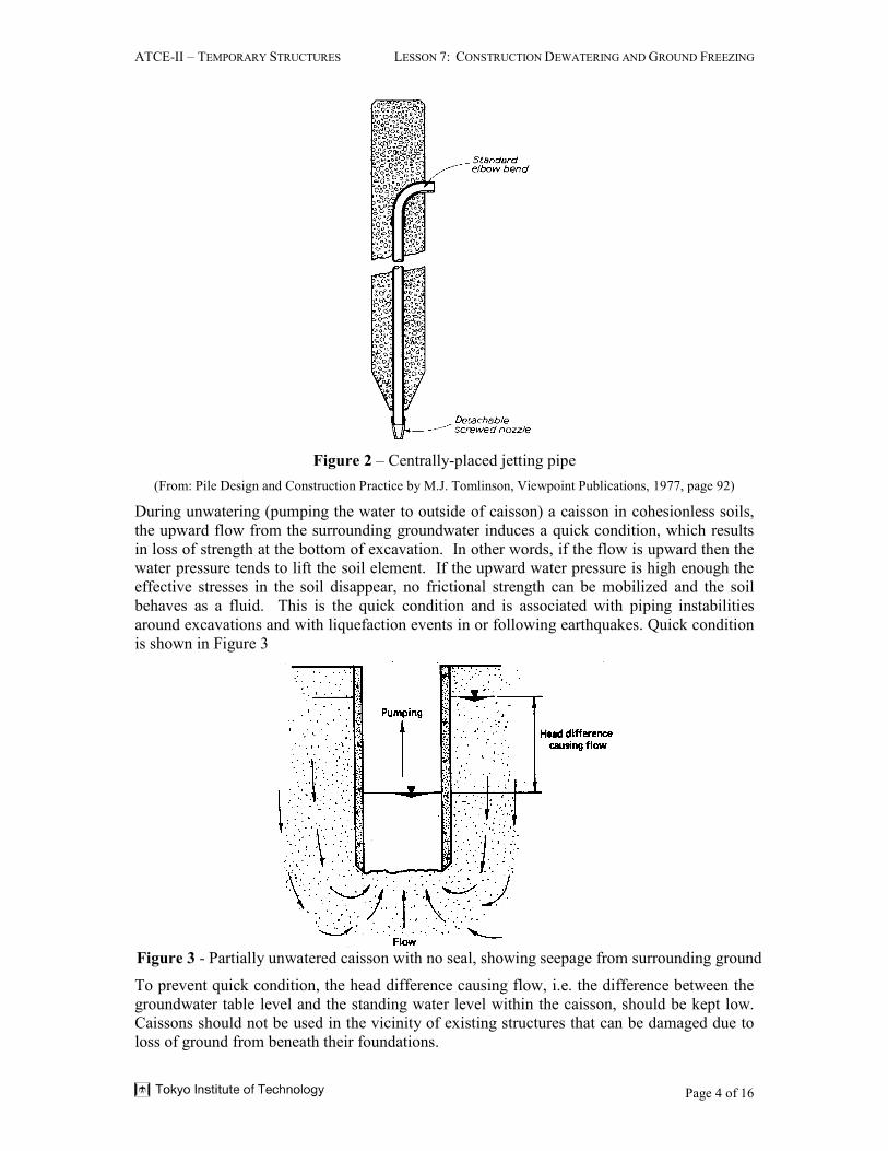
Jetting is applicable to those situations where structure must be driven through cohesionless
soil materials to greater depths. Water jets can be used to displace granular soils from beneath
the toe of a pile or caisson. Jetting is accomplished by pumping water through pipes attached
to the side or center of the structure as it is driven. The flow of water creates a “quick”
condition and thereby reduces skin friction along the sides of the driven structure. The result
is that the structure drives more easily. Figure 2 illustrates a centrally-placed jetting pipe
schematically.
ATCE-II – TEMPORARY STRUCTURES LESSON 7: CONSTRUCTION DEWATERING AND GROUND FREEZING
Page 4 of 16
Figure 2 – Centrally-placed jetting pipe
(From: Pile Design and Construction Practice by M.J. Tomlinson, Viewpoint Publications, 1977, page 92)
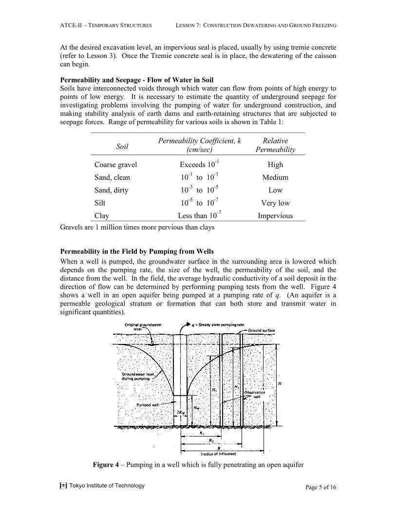
During unwatering (pumping the water to outside of caisson) a caisson in cohesionless soils,
the upward flow from the surrounding groundwater induces a quick condition, which results
in loss of strength at the bottom of excavation. In other words, if the flow is upward then the
water pressure tends to lift the soil element. If the upward water pressure is high enough the
effective stresses in the soil disappear, no frictional strength can be mobilized and the soil
behaves as a fluid. This is the quick condition and is associated with piping instabilities
around excavations and with liquefaction events in or following earthquakes. Quick condition
is shown in Figure 3
Figure 3 - Partially unwatered caisson with no seal, showing seepage from surrounding ground
To prevent quick condition, the head difference causing flow, i.e. the difference between the
groundwater table level and the standing water level within the caisson, should be kept low.
Caissons should not be used in the vicinity of existing structures that can be damaged due to
loss of ground from beneath their foundations.
ATCE-II – TEMPORARY STRUCTURES LESSON 7: CONSTRUCTION DEWATERING AND GROUND FREEZING
Page 5 of 16
At the desired excavation level, an impervious seal is placed, usually by using tremie concrete
(refer to Lesson 3). Once the Tremie concrete seal is in place, the dewatering of the caisson
can begin.
Permeability and Seepage - Flow of Water in Soil
Soils have interconnected voids through which water can flow from points of high energy to
points of low energy. It is necessary to estimate the quantity of underground seepage for
investigating problems involving the pumping of water for underground construction, and
making stability analysis of earth dams and earth-retaining structures that are subjected to
seepage forces. Range of permeability for various soils is shown in Table 1:
SoilPermeability Coefficient, k
(cm/sec)
Relative
Permeability
Coarse gravel Exceeds 10-1
High
Sand, clean 10-1
to 10-3
Medium
Sand, dirty 10-3
to 10-5
Low
Silt 10-5
to 10-7
Very low
Clay Less than 10-7
Impervious
Gravels are 1 million times more pervious than clays
Permeability in the Field by Pumping from Wells
When a well is pumped, the groundwater surface in the surrounding area is lowered which
depends on the pumping rate, the size of the well, the permeability of the soil, and the
distance from the well. In the field, the average hydraulic conductivity of a soil deposit in the
direction of flow can be determined by performing pumping tests from the well. Figure 4
shows a well in an open aquifer being pumped at a pumping rate of q. (An aquifer is a
permeable geological stratum or formation that can both store and transmit water in
significant quantities).
Figure 4 – Pumping in a well which is fully penetrating an open aquifer

ATCE-II – TEMPORARY STRUCTURES LESSON 7: CONSTRUCTION DEWATERING AND GROUND FREEZING
Page 6 of 16
The basic mathematical relationships concerning flow in soils assume that aquifer extend
horizontally in all directions beyond the area of interest and its thickness is uniform
throughout and it is isotropic, i.e., permeability in the horizontal and vertical directions is the
same. The pumping rate from a well in an open aquifers is (Figure 3):
( )
−
=
1
2
2
1
2
2
ln
R
R
HHkq
π
where q = Water flowing through the soil at a constant rate
k = the coefficient of permeability (aka: Hydraulic conductivity, a material’s constant)
R1 and R2 = distances of observation wells from the well where pumping is performed
H1 and H2 = drawdowns in the observation wells caused by pumping
If there are no observation wells, then q can be estimated by the following equation:
( )
−=
W
W
R
R
HHkq
ln
22π
where H, HW, R and RW are as shown in Figure 3.
Example
Consider the case of pumping from a well in an unconfined permeable layer underlain by an
impermeable stratum. Given:
q = 26 ft3/min
H1 = 15.7 ft at R1 = 100 ft
H2 = 18.0 ft at R2 = 200 ft
Calculate the hydraulic conductivity (in ft/min) of the permeable layer.
( )( ) ( )( ) ft/min 074.0
7.1518
100200ln26ln
22
1
2
2
1
2
2
=−
=
−=
ππ R
R
HH
qk
Dewatering Methods - Wellpoints
The wellpoint consists of a slotted or perforated pipe which is covered with a screen mesh. At
the foot of this pipe is an orifice which permits jetting of the pipe into the ground during
installation. A well-point dewatering system consists of a series of closely placed small-
diameter wells installed to shallow depths. These wells are connected to a pipe or header that
surrounds the excavation and is attached to a vacuum pump. The construction steps in the
wellpoint system are:
1. the wellpoints are jetted into the ground;
2. the annulars void is filled with filter media;
3. the wellpoints are connected to a header pipe by means of a riser;
4. the header pipe is connected to suction pumps for pumping.
ATCE-II – TEMPORARY STRUCTURES LESSON 7: CONSTRUCTION DEWATERING AND GROUND FREEZING
Page 7 of 16
Figure 5 shows small pipes, up to 2.5 inches in diameter, connected to screens at the bottom
and to a vacuum header pipe at the surface, which constitute a wellpoint system.
Figure 5 – Wellpoint system
Wellpoints typically have capacities ranging from a fraction of a gallon a minute to 100
gallons per minute and they may be used in single stages or in multiple stages to accomplish
deep dewatering.
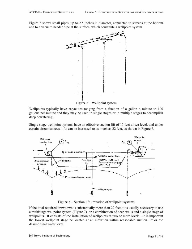
Single stage wellpoint systems have an effective suction lift of 15 feet at sea level, and under
certain circumstances, lifts can be increased to as much as 22 feet, as shown in Figure 6.
Figure 6 – Suction lift limitation of wellpoint systems
If the total required drawdown is substantially more than 22 feet, it is usually necessary to use
a multistage wellpoint system (Figure 7), or a combination of deep wells and a single stage of
wellpoints. It consists of the installation of wellpoints at two or more levels. It is important
the lowest wellpoint stage be located at an elevation within reasonable suction lift or the
desired final water level.
ATCE-II – TEMPORARY STRUCTURES LESSON 7: CONSTRUCTION DEWATERING AND GROUND FREEZING
Page 8 of 16
Figure 7 – Multi-stage wellpoint system
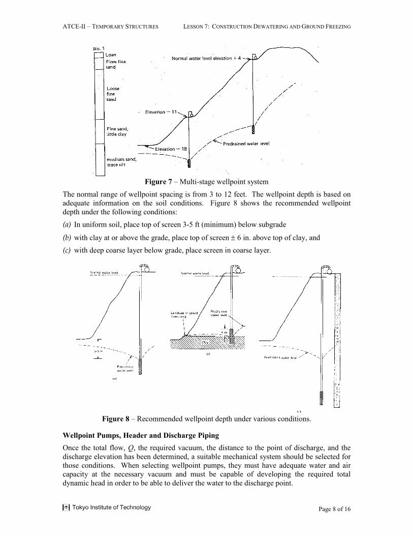
The normal range of wellpoint spacing is from 3 to 12 feet. The wellpoint depth is based on
adequate information on the soil conditions. Figure 8 shows the recommended wellpoint
depth under the following conditions:
(a) In uniform soil, place top of screen 3-5 ft (minimum) below subgrade
(b) with clay at or above the grade, place top of screen ± 6 in. above top of clay, and
(c) with deep coarse layer below grade, place screen in coarse layer.
Figure 8 – Recommended wellpoint depth under various conditions.
Wellpoint Pumps, Header and Discharge Piping
Once the total flow, Q, the required vacuum, the distance to the point of discharge, and the
discharge elevation has been determined, a suitable mechanical system should be selected for
those conditions. When selecting wellpoint pumps, they must have adequate water and air
capacity at the necessary vacuum and must be capable of developing the required total
dynamic head in order to be able to deliver the water to the discharge point.
ATCE-II – TEMPORARY STRUCTURES LESSON 7: CONSTRUCTION DEWATERING AND GROUND FREEZING
Page 9 of 16
Single pump or multiple pumps may be used, depending on availability of equipment and job
conditions. If multiple pumps are used, they should be spaced along the header, or they can
be grouped into one single pump station. In a single pump station only one discharge line is
used, but in this case large header pipes are used to bring the water to the central pump station
without excessive friction. Redundant or standby pumps must be provided, installed and be
ready to operate in case of malfunction of the regular pumps or during maintenance or repair
of those pumps.
For high volume pumping a suction manifold may be used, which reduces the water velocity
in the header line at the pump. The manifold also causes smooth flow in the critical approach
to the pump entrance, reducing cavitation, which will increase the capacity of the pump.
Header lines are sized to keep friction at acceptable levels. Valves are used to facilitate
installation, trouble shouting, repair and removal. The discharge lines should be braced and
strapped, wher pressure is moderate to high. The arrangement and location of header lines,
pumps and discharge should be selected in accordance with the plan and schedule of
construction sequence and activities so that it is convenient during exvavation, but also will
not interfere with construction and backfill operations, in order to prevent relocation and
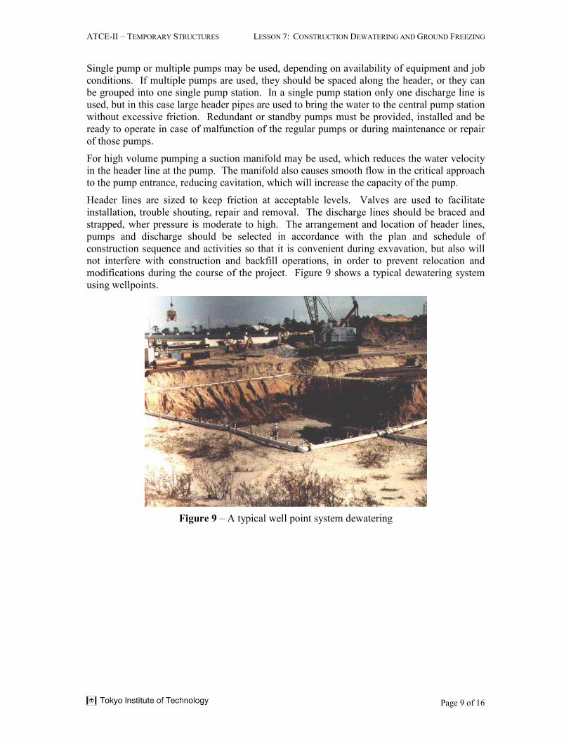
modifications during the course of the project. Figure 9 shows a typical dewatering system
using wellpoints.
Figure 9 – A typical well point system dewatering
ATCE-II – TEMPORARY STRUCTURES LESSON 7: CONSTRUCTION DEWATERING AND GROUND FREEZING
Page 10 of 16
Ground Freezing
The principle of ground freezing is to change the water in the soil into a solid wall of ice.
This wall of ice is completely impermeable. Ground freezing is used for groundwater cutoff,
for earth support, for temporary underpinning, for stabilization of earth for tunnel excavation,
to arrest landslides and to stabilize abandoned mineshafts. The principals of ground freezing
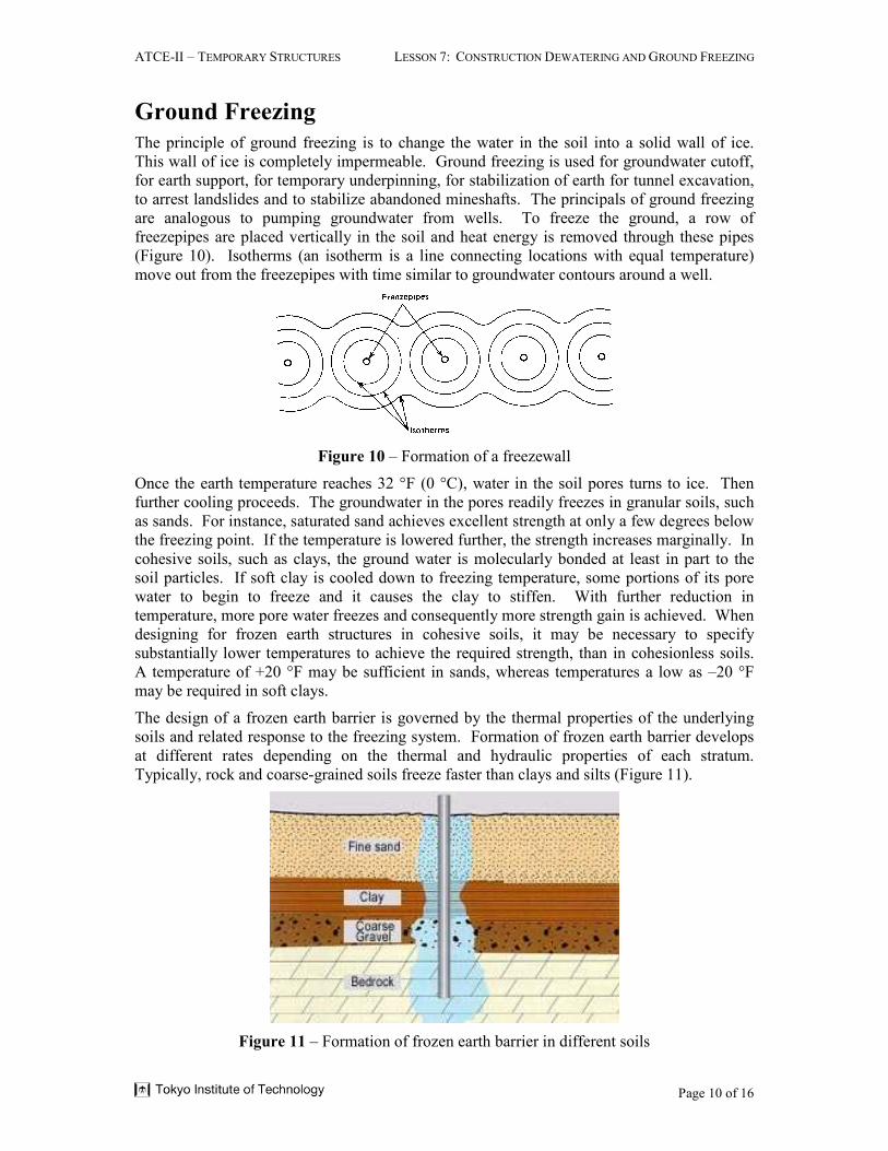
are analogous to pumping groundwater from wells. To freeze the ground, a row of
freezepipes are placed vertically in the soil and heat energy is removed through these pipes
(Figure 10). Isotherms (an isotherm is a line connecting locations with equal temperature)
move out from the freezepipes with time similar to groundwater contours around a well.
Figure 10 – Formation of a freezewall
Once the earth temperature reaches 32 °F (0 °C), water in the soil pores turns to ice. Then
further cooling proceeds. The groundwater in the pores readily freezes in granular soils, such
as sands. For instance, saturated sand achieves excellent strength at only a few degrees below
the freezing point. If the temperature is lowered further, the strength increases marginally. In
cohesive soils, such as clays, the ground water is molecularly bonded at least in part to the
soil particles. If soft clay is cooled down to freezing temperature, some portions of its pore
water to begin to freeze and it causes the clay to stiffen. With further reduction in
temperature, more pore water freezes and consequently more strength gain is achieved. When
designing for frozen earth structures in cohesive soils, it may be necessary to specify
substantially lower temperatures to achieve the required strength, than in cohesionless soils.
A temperature of +20 °F may be sufficient in sands, whereas temperatures a low as –20 °F
may be required in soft clays.
The design of a frozen earth barrier is governed by the thermal properties of the underlying
soils and related response to the freezing system. Formation of frozen earth barrier develops
at different rates depending on the thermal and hydraulic properties of each stratum.
Typically, rock and coarse-grained soils freeze faster than clays and silts (Figure 11).
Figure 11 – Formation of frozen earth barrier in different soils
ATCE-II – TEMPORARY STRUCTURES LESSON 7: CONSTRUCTION DEWATERING AND GROUND FREEZING
Page 11 of 16
When soft clay is cooled to the freezing point, some portion of its pore water begins to freeze
and clay begins to stiffen. If the temperature is further reduced, more of the pore water
freezes and the strength of the clay markedly increases. When designing frozen earth
structures in clay it may be necessary to provide for substantially lower temperatures to
achieve the required strengths. A temperature of +20 °F may be adequate in sands, whereas
temperatures as low as –20 °F may be required in soft clay.
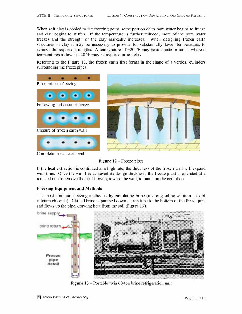
Referring to the Figure 12, the frozen earth first forms in the shape of a vertical cylinders
surrounding the freezepipes.
Pipes prior to freezing
Following initiation of freeze
Closure of frozen earth wall
Complete frozen earth wall
Figure 12 – Freeze pipes
If the heat extraction is continued at a high rate, the thickness of the frozen wall will expand
with time. Once the wall has achieved its design thickness, the freeze plant is operated at a
reduced rate to remove the heat flowing toward the wall, to maintain the condition.
Freezing Equipment and Methods
The most common freezing method is by circulating brine (a strong saline solution – as of
calcium chloride). Chilled brine is pumped down a drop tube to the bottom of the freeze pipe
and flows up the pipe, drawing heat from the soil (Figure 13).
Figure 13 – Portable twin 60-ton brine refrigeration unit
ATCE-II – TEMPORARY STRUCTURES LESSON 7: CONSTRUCTION DEWATERING AND GROUND FREEZING
Page 12 of 16
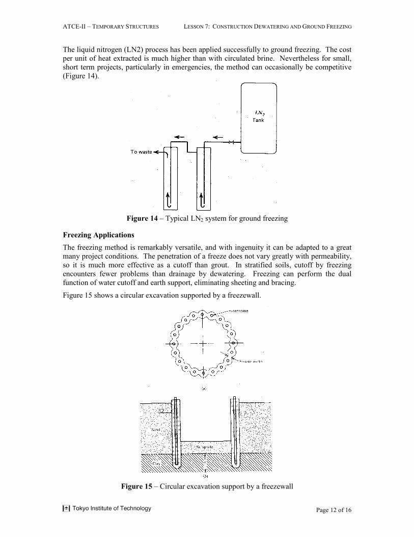
The liquid nitrogen (LN2) process has been applied successfully to ground freezing. The cost
per unit of heat extracted is much higher than with circulated brine. Nevertheless for small,
short term projects, particularly in emergencies, the method can occasionally be competitive
(Figure 14).
Figure 14 – Typical LN2 system for ground freezing
Freezing Applications
The freezing method is remarkably versatile, and with ingenuity it can be adapted to a great
many project conditions. The penetration of a freeze does not vary greatly with permeability,
so it is much more effective as a cutoff than grout. In stratified soils, cutoff by freezing
encounters fewer problems than drainage by dewatering. Freezing can perform the dual
function of water cutoff and earth support, eliminating sheeting and bracing.
Figure 15 shows a circular excavation supported by a freezewall.
Figure 15 – Circular excavation support by a freezewall
ATCE-II – TEMPORARY STRUCTURES LESSON 7: CONSTRUCTION DEWATERING AND GROUND FREEZING
Page 13 of 16
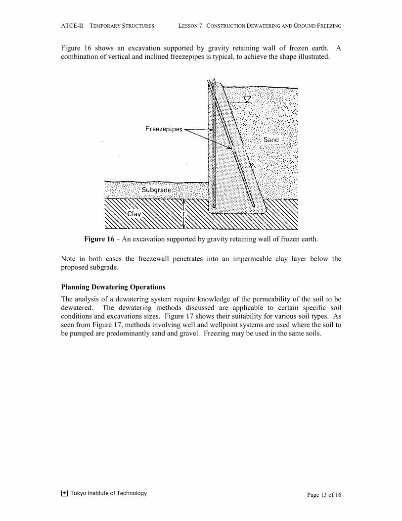
Figure 16 shows an excavation supported by gravity retaining wall of frozen earth. A
combination of vertical and inclined freezepipes is typical, to achieve the shape illustrated.
Figure 16 – An excavation supported by gravity retaining wall of frozen earth.
Note in both cases the freezewall penetrates into an impermeable clay layer below the
proposed subgrade.
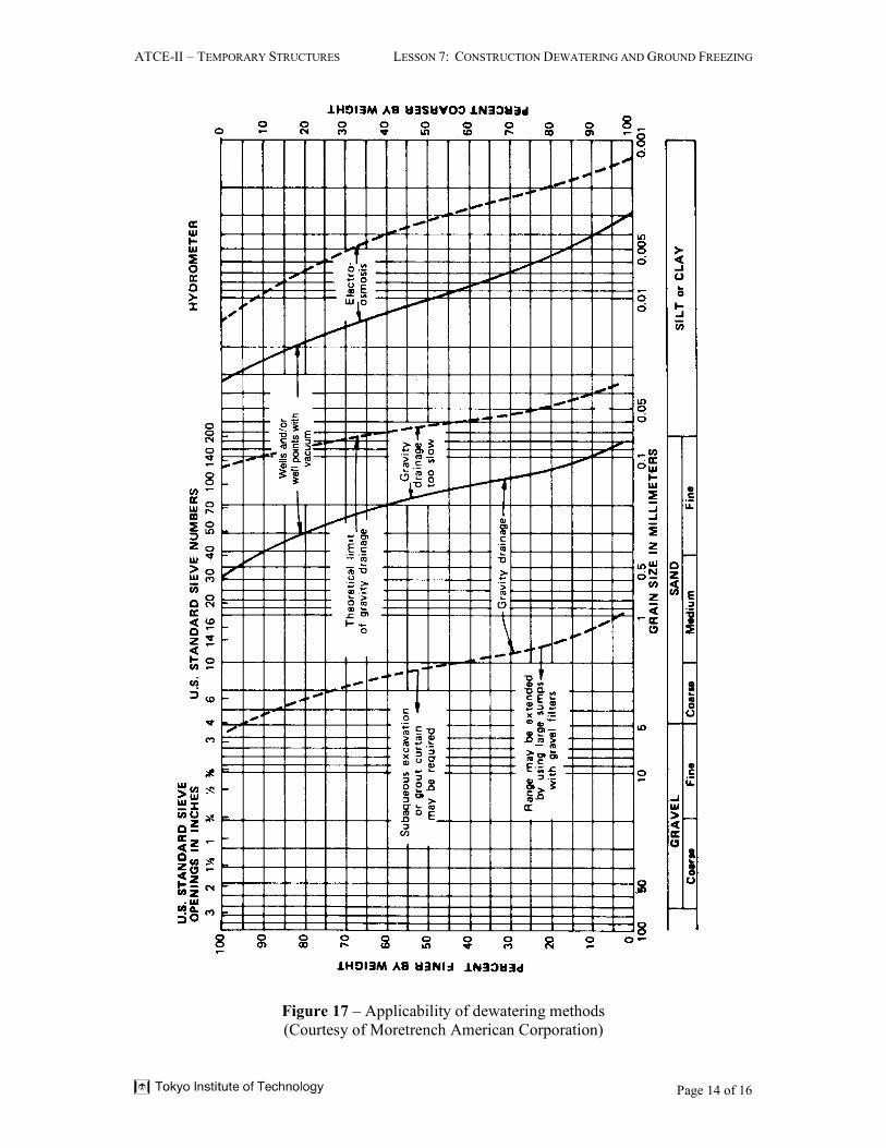
Planning Dewatering Operations
The analysis of a dewatering system require knowledge of the permeability of the soil to be
dewatered. The dewatering methods discussed are applicable to certain specific soil
conditions and excavations sizes. Figure 17 shows their suitability for various soil types. As
seen from Figure 17, methods involving well and wellpoint systems are used where the soil to
be pumped are predominantly sand and gravel. Freezing may be used in the same soils.
ATCE-II – TEMPORARY STRUCTURES LESSON 7: CONSTRUCTION DEWATERING AND GROUND FREEZING
Page 14 of 16
Figure 17 – Applicability of dewatering methods
(Courtesy of Moretrench American Corporation)
ATCE-II – TEMPORARY STRUCTURES LESSON 7: CONSTRUCTION DEWATERING AND GROUND FREEZING
Page 15 of 16
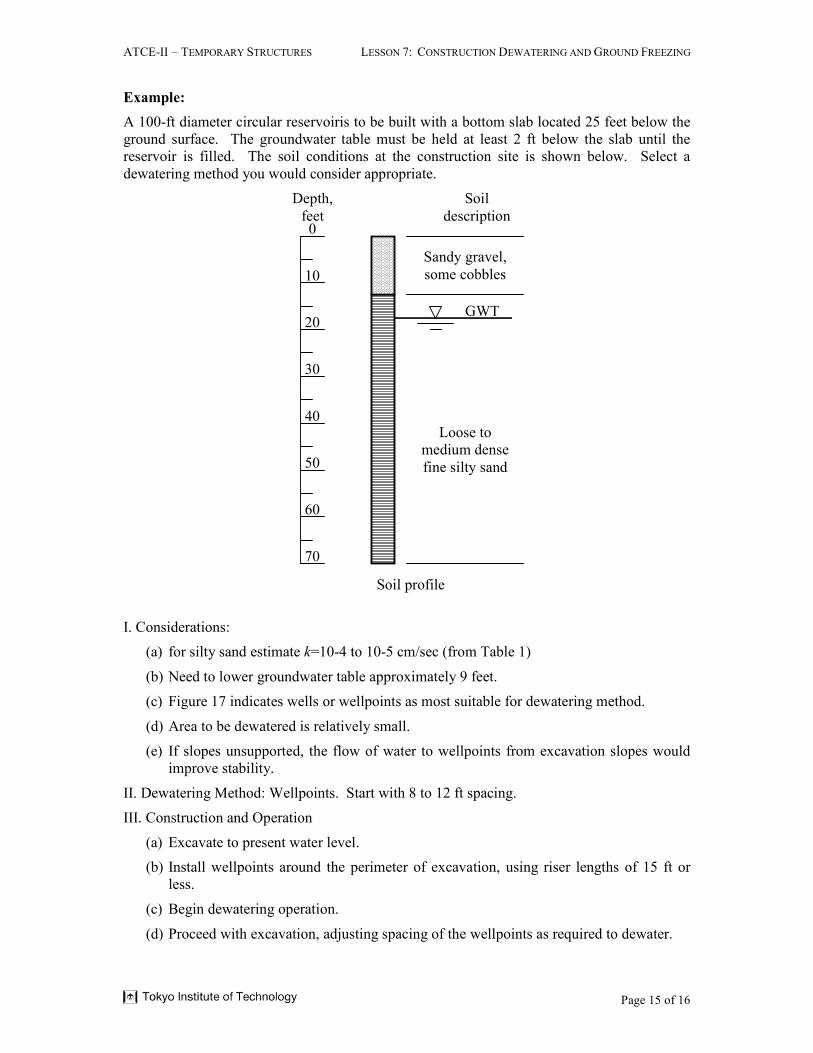
Example:
A 100-ft diameter circular reservoiris to be built with a bottom slab located 25 feet below the
ground surface. The groundwater table must be held at least 2 ft below the slab until the
reservoir is filled. The soil conditions at the construction site is shown below. Select a
dewatering method you would consider appropriate.
0
10
20
30
40
50
60
70
Depth,
feet
Soil
description
Sandy gravel,
some cobbles
Loose to
medium dense
fine silty sand
GWT
Soil profile
I. Considerations:
(a) for silty sand estimate k=10-4 to 10-5 cm/sec (from Table 1)
(b) Need to lower groundwater table approximately 9 feet.
(c) Figure 17 indicates wells or wellpoints as most suitable for dewatering method.
(d) Area to be dewatered is relatively small.
(e) If slopes unsupported, the flow of water to wellpoints from excavation slopes would
improve stability.
II. Dewatering Method: Wellpoints. Start with 8 to 12 ft spacing.
III. Construction and Operation
(a) Excavate to present water level.
(b) Install wellpoints around the perimeter of excavation, using riser lengths of 15 ft or
less.
(c) Begin dewatering operation.
(d) Proceed with excavation, adjusting spacing of the wellpoints as required to dewater.
ATCE-II – TEMPORARY STRUCTURES LESSON 7: CONSTRUCTION DEWATERING AND GROUND FREEZING
Page 16 of 16
Summary
Today’s improved well equipment and well construction techniques make possible the
dewatering of many projects with wells and wellspoints. Other methods of groundwater
control that have been developed and used such as ground freezing, slurry trenches, cast in
situ diaphragm walls, etc. have had some degree of success in the specific job conditions to
which they are suited. Though construction dewatering has not been reduced to an exact
science yet, the selection of the dewatering system should hinge on the experience and
professional judgement of the engineer based on the soil materials, the source of water, and
the demands of the project.
With this lesson, this course come to an end. I hope that the materials presented in the
preceeding eight lessons will be of value in your professional career. The M.K. Hurd book is
a classic concrete formwork book and I am sure you will be referring to it any time you
design formwork.