Constructing Mission Critical Solutions using Superdome Ken Pomaranski Hewlett Packard Company...
37
Constructing Mission Critical Solutions using Superdome Ken Pomaranski Hewlett Packard Company [email protected]
-
Upload
doris-shaw -
Category
Documents
-
view
220 -
download
2
Transcript of Constructing Mission Critical Solutions using Superdome Ken Pomaranski Hewlett Packard Company...

Constructing Mission Critical Solutions using Superdome
Ken Pomaranski
Hewlett Packard Company

High Availability High Availability is…
• built, managed, and measured
• hardware, system software, applications & middleware, and IT processes designed to minimize both planned and unplanned downtime
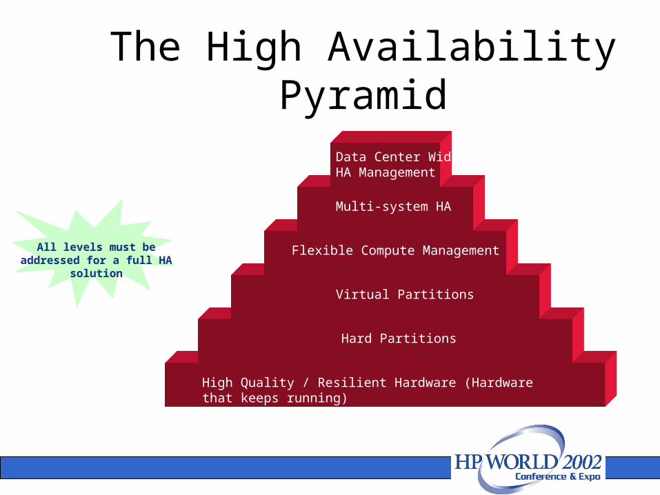
High Quality / Resilient Hardware (Hardware that keeps running)
Hard Partitions
Virtual Partitions
Flexible Compute Management
Multi-system HA
Data Center Wide HA Management
All levels must be addressed for a full HA
solution
The High Availability Pyramid

What we will discuss today:
• Setting up Superdome to deliver max Single System HA (SSHA)
• Reducing planned downtime & downtime due to user error across the data center
• Measurement of Availability
I will focus on the very bottom and very top of the pyramid

Max Single System HA

System Crossbar Backplane
Bulk Power
SuppliesCrossbar Chip
uptime institute certified
high reliability process (10x ‘standard’)
Isolated buses
IO error containment
PCI OLAR
online wire sparing
redundant and hot-swap system fans
Superdome reliability / resiliency features at a glance
PCI Backplane
All Hot-Plug
I/O Controller
12 PCI I/O Slots
. . .
All Hot-Plug
I/O Controller
12 PCI I/O Slots
. . .
All Hot-Plug
I/O Controller
12 PCI I/O Slots
. . .
All Hot-Plug
I/O Controller
12 PCI I/O Slots
. . .
PCI Backplane
PCI Backplane PCI Backplane
CPU
Memory
Cell Board
CELLController
CPU
CPU
CPU
CPU
Memory
Cell Board
CELLController
CPU
CPU
CPU
CPU
Memory
Cell Board
CELLController
CPU
CPU
CPU
CPU
Memory
Cell Board
CELLController
CPU
CPU
CPU
CPU
Memory
Cell Board
CELLController
CPU
CPU
CPU
CPU
Memory
Cell Board
CELLController
CPU
CPU
CPU
CPU
Memory
Cell Board
CELLController
CPU
CPU
CPU
CPU
Memory
Cell Board
CELLController
CPU
CPU
CPU
Crossbar Chip
Fully redundant power
dynamic memory resiliency, ‘chip
spare’
highly reliable (10x), fully isolated xbar
ports
dynamic processor resiliency, cache
ECC
Redundant power (2003)

Fault Tolerant Bar graph
All HW faults
hard failures covered by HW redundancy & hotswap. EMS reports events
HW correctable errors. EMS monitors for trends, alerts user (or HP directly) if a planned event is required to rectify the problem
Uncorrectable error Causes system crash
faults covered by HA
correct configuration of EMS is vital to delivering SSHA

Dynamic Processor Resilience
Processor detects single bit error in data cache and vectors to PDC PDC generates low priority machine check (LPMC) LPMC handler logs info to diag2 driver Diaglogd daemon pulls lpmc log info from diag2 and passes it to the EMS LPMC monitor If this is the 3rd LPMC within 24 hours:
Call cpu_deallocate to stop dispatching applications on the processor If iCOD machine, allocate idle processor Call pdc_pat_cpu to have pdc disable the processor the next time the system boots Generate event to customer/HP
PCX-W Processor
Processor
Data Cache
Single BitErrorLPMC
Handlerdiag2Driver
Diaglogddaemon
EMS LPMCMonitor
Customer orHP RC
EMSEvent
PDC
Kernel SpaceFirmware Hardware
UserSpace
pdc_pat_cpucall
Scheduler
spu_deallocatecall
LPMC
diag0Driver
DPR makes the system fully resilient to CPU cache errors which is one of the greatest contributors to system downtime. Cache errors contribute 80% of total CPU hardware errors.

Dynamic Memory Resilience (DMR)
Main memory failures are demonstrated to be the second largest cause of customer downtime. Great care has been taken to address this failure mode in Superdome with these specific features:
• Memory ‘chip spare’: the ability of the system to continue to run in the face of any single or multi-bit chip error on a DRAM.
• Dynamic memory resiliency (DMR): is the system’s ability to de-allocate failed memory pages online. It works similar to Dynamic Processor Resiliency in that if a location in memory proves to be ‘questionable’ (i.e., exhibits persistent errors), that memory will be de-allocated online, with no customer visible impact.
• HW memory scrubbing: refers to the HW feature that automatically removes single bit errors (SBE) that reside in main memory.
The combination of these features have nearly eliminated memory as a cause of downtime in HP systems.

to CPU
ECC word 1
ECC word 2
ECC word 3
ECC word 4
4 data bits per access
4 data bits per access
bit 1 bit 144
SDRAM 1 SDRAM 144
Memory ‘chip sparing’
Note: no SDRAM contributes more than one bit to each ECC word. Therefore, memory system is ‘redundant’

HP Fault ManagementIncrease system availability by moving from reactive fault detection, diagnosis and repair to proactive fault detection, diagnosis and repair.
• Detect problems automatically as close as possible to when they actually occur
• Diagnose problems automatically at the time of detection
• Automatically report in understandable text:
A description of the problem
The likely cause(s) of the problem
The recommended action(s) to resolve the problem
Detailed information about the problem
• Tools are available to repair or recover from the fault

Fault Management Impact
UserNotified
CrashDump
Response CenterContacted
CE ResponseTime
DiagnoseTime
RepairTime
Retest/verifyFix
Reboot
DatabaseRecovery
ApplicationRestart
RepairTime
UserNotified
CrashDump
Response CenterContacted
CE ResponseTime
DiagnoseTime Retest/verify
Fix
RebootDatabaseRecovery
ApplicationRestart
Fault OccursWithout Fault Management
With Fault Management
5
20
60
120
240
10 1720 25 2
Time inMinutes
1
20
15
10 120 10 175 25 2Time inMinutes
Total: 6 Hours 19 Minutes
Total: 3 Hours 24 Minutes
Fault Management impactareas in green

Hardware Troubleshooting Tools
Power-on Self-Test (POST)
• Firmware based device diagnostics
Offline Diagnostic Environment (ODE)
• Processor, memory, I/O diagnostics• Firmware update utilities• ISL/EFI based (offline)
Support Tools Manager
• Diagnostics, verifiers, exercisers• Information, expert utilities • Firmware update, logtool• Graphical, menu, cmd line interfaces• User space application (online)
EMS Hardware Monitors
• Processors, memory, I/O, peripherals• FC adapters, switches, hubs, SCSI Mux• UPS, core electronics, etc.
Focus is on testing resources that are needed to boot to ISL or EFI
Focus is on testing resources that are needed to boot the system
Focus is on verifying all hardware is properly connected and configured and on reproducing intermittent problems
Focus is monitoring the health of all hardware components and generating close to real time events when problems develop
Proactive
Reactive

Hardware monitoring
Hardware Resource
EMS Hardware Monitor
Event Monitoring
Service (EMS)
Peripheral Status Monitor
Changes all EMS events into a HW state:
UP or DOWN
To Serviceguard
Notification

Building a Monitoring Request
Hardware Event Monitor
This sets the hardware you want
monitored
Severity Level Critical = 5 Serious = 4 Major = 3 Minor = 2 Informational = 1
Operator
=, >, <
>=, <=
!
Together, these settings identify what events you
want reported
Notification Method
You can select one notification method
for each request

Notification Methods• EMAIL* - sends notification to the specified email address• TEXTLOG* - sends notification to specified file• SNMP - sends notification using SNMP traps• CONSOLE - sends notification to the system console• TCP - sends notification to the specified target host and
port• UDP - sends notification to the specified target host and
port• OPC - sends notification to OpenView ITO applications
(available only on systems with OpenView installed).• SYSLOG - sends notification to the system logOnly one notification method can be selected for each monitor request, consequently
you will need to create multiple requests to direct event notification to different targets. Those notification methods denoted by a ‘* ‘ are the only methods that deliver the entire content of the event message.

To run the Monitoring Request Manager, type: /etc/opt/resmon/lbin/monconfig
The opening screen looks like this:
========================================================
========== Event Monitoring Service ===========
========== Monitoring Request Manager ===========
========================================================
EVENT MONITORING IS CURRENTLY ENABLED <== MONITORING STATUS
========================================================
====== Monitoring Request Manager Main Menu ========
========================================================
Select:
(S)how current monitoring requests configured via monconfig
(C)heck detailed monitoring status
(L)ist descriptions of available monitor
(A)dd a monitoring request <== MAIN MENU
(D)elete a monitoring request SELECTION
(M)odify an existing monitoring request OPTIONS
(E)nable Monitoring
(K)ill (disable) monitoring
(H)elp
(Q)uit
Enter selection: [s]

The following sample is representative of the types of entries displayed for detailed monitoring status.
For /storage/events/disks/default/10_12_5.2.0:
Events >= 1 (INFORMATION) Goto TEXTLOG; file=/var/opt/resmon/log/event.log
Events >= 4 (MAJOR WARNING) Goto SYSLOG
Events >= 4 (MAJOR WARNING) Goto EMAIL; addr=root
Events = 5 (CRITICAL) Goto TCP; host=hpbs1266.boi.hp.com port=53327
For /adapters/events/FC_adapter/8_12.8:
Events >= 1 (INFORMATION) Goto TEXTLOG; file=/var/opt/resmon/log/event.log
Events >= 4 (MAJOR WARNING) Goto SYSLOG
Events >= 4 (MAJOR WARNING) Goto EMAIL; addr=root
>/connectivity/events/multiplexors/FC_SCSI_mux ... NOT MONITORING.
(Possibly there is no hardware to monitor.)
>/system/events/memory ... OK.
For /system/events/memory/49:
Events >= 1 (INFORMATION) Goto TEXTLOG; file=/var/opt/resmon/log/event.log
Events >= 4 (MAJOR WARNING) Goto SYSLOG
Events >= 4 (MAJOR WARNING) Goto EMAIL; addr=root
Events >= 4 (MAJOR WARNING) Goto TCP; host=hpbs1266.boi.hp.com port=53327
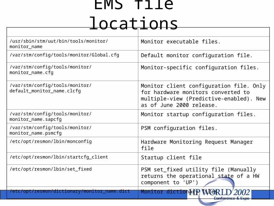
EMS file locations
/usr/sbin/stm/uut/bin/tools/monitor/monitor_name
Monitor executable files.
/var/stm/config/tools/monitor/Global.cfg Default monitor configuration file.
/var/stm/config/tools/monitor/monitor_name.cfg
Monitor-specific configuration files.
/var/stm/config/tools/monitor/default_monitor_name.clcfg
Monitor client configuration file. Only for hardware monitors converted to multiple-view (Predictive-enabled). New as of June 2000 release.
/var/stm/config/tools/monitor/monitor_name.sapcfg
Monitor startup configuration files.
/var/stm/config/tools/monitor/monitor_name.psmcfg
PSM configuration files.
/etc/opt/resmon/lbin/monconfig Hardware Monitoring Request Manager file
/etc/opt/resmon/lbin/startcfg_client Startup client file
/etc/opt/resmon/lbin/set_fixed PSM set_fixed utility file (Manually returns the operational state of a HW component to ‘UP’)
/etc/opt/resmon/dictionary/monitor_name.dict Monitor dictionary files

EMS Tips• Keep hardware monitoring enabled to protect your system from
undetected failures.• Integrate the peripheral status monitor (PSM) into your
MC/ServiceGuard strategy.– Monitor (PSM) Included with the hardware event monitors, the PSM is
a monitor daemon that acts as a hardware status monitor by converting events to changes in hardware resource status. This provides compatibility with MC/ServiceGuard, which uses changes in status to manage cluster resources.
• Utilize the many notification methods available.• Use email and/or textfile notification methods for all your
requests.• Use the `All monitors' option when creating a monitoring request.• Easily replicate your hardware monitoring on all your systems.
– The monitor configuration files live in /var/stm/config/tools/monitor.– Simply copy all of the hardware monitor configuration files to each
system that will use the same monitoring.

Partitioning

Partition 1
Partition 2
Cell 1
Cell 4 Cell 3
Cell 2
CrossbarFabric
Cell 1 Cell 2 Cell 3 Cell 4
Shared Backplane Bus
Partition 1 Partition 2
Hard Partition Isolation
HP Architecture
Competitor Architecture
On the HP system, the crossbar logically separates the two physical partitions to provide performance and isolation.
The competitor’s shared backplane has all its cells competing for the same electrical bus. In this design, a snoopy bus-coherency scheme requires all transactions to be broadcast to and processed by all system cells. The high-queuing delays and saturation of the shared backplane bus can limit performance scaling
HA ManagementData Center Level

Customer Site MCSC
HP Support Node
Remote Support Resource
SN Router
Customer Mail Server
Network Support Repository
Workflow Management Systems
HP-UX WindowsMission Critical Systems
HP-UX Windows
HASEs
Clarify (WFM) Session
HP Mail Relay
Satellite Server
Internet Email
Alternate Email
HPEN Workflow Data
CA Workflow Data
E-mail Data
CA Server
HAO Components and Use Model

HP Event Types and Information
HP Event Notifier sends the following information to the MCSC:
Type Timeframe Transmission Size
Fault Events Real time – as occurred or polled interval
5 – 10 Kb
Chassis Code Polled every ten minutes
Up to 100 Kb (normally smaller)
EMS logs Polled once per day from client’s Mission Critical systems
Up to 500 Kb (normally smaller)

User Error Reduction Using HAO Tools

HP Configuration TrackerTracker automatically collects configuration data for systems and network interconnect devices. It identifies configuration differences to answer the critical question: “What’s Changed?”
Tracker performs the following tasks:•Automatically collects data daily or weekly.•Significantly reduces time to gather critical information .•Allows HP System Recovery Specialist and IT Administrator to view the same critical information.
•Transmits hardware, O/S, network interconnect configuration information to MCSC for proactive analysis.
•Creates “user-defined” collectibles to expand collection items.•Transports configuration data, alarms and log files to the MCSC daily.

HP Configuration AnalyzerThe HP Configuration Analyzer (CA) automatically analyzes customer configurations using patch analyzers and notifies the MCSC of potential problems.
CA benefits include:• Proactive analysis of Application Patch Sets.• Flexible analysis scheduling for all analyzers.• Automatic generation of in workflow management cases that
notify HP Support Personnel of potential problems.• Access to customer configuration data at the MCSC.

Measuring Availability Across the Data Center using
HA Meter

Defining Availability
HA Meter documents all downtime (planned and unplanned) and quantifies availability of a system, cluster, package, or node.
Availability calculations are based on internal timestampsreported in milliseconds, UTC (Universal Time Coordinate).
(total elapsed time - sum of down times)
total elapsed time
100*

Shutdown Versus System Crash
Normal Operation (shutdown):
Crash Events:
Shutdown
Shutdown event saved in event log.
System crash event saved inevent log. Startup event saved in event log.
SystemCrash
timestamp
timestamp
Startup event saved in event log.

Execute a Planned Shutdown
• To shut down a system and enter a shutdown cause, follow these basic steps:1. Shut down the HA Meter Agent using the
shutdown_ham command.
2. Enter the cause code for the system shutdown (cause codes are listed on the following page).
• NOTE: This is the only HA Meter procedure that customers may execute on their own.
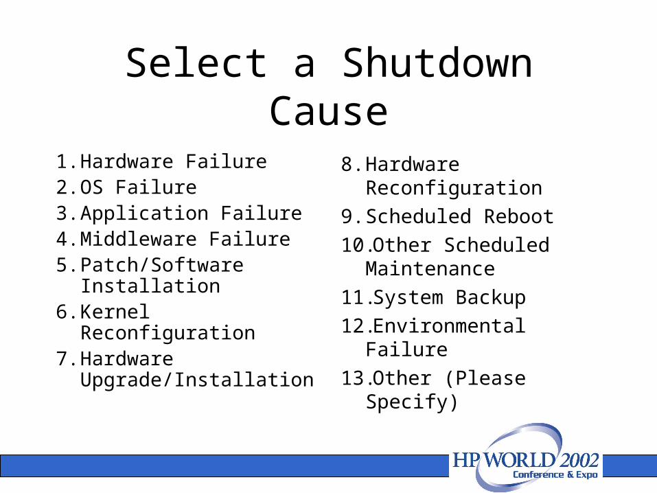
Select a Shutdown Cause
1. Hardware Failure2. OS Failure3. Application Failure4. Middleware Failure5. Patch/Software
Installation6. Kernel Reconfiguration7. Hardware
Upgrade/Installation
8. Hardware Reconfiguration
9. Scheduled Reboot
10.Other Scheduled Maintenance
11.System Backup
12.Environmental Failure
13.Other (Please Specify)
Defining Downtime
• HA Meter distinguishes planned versus unplanned downtime solely on the basis of whether the shutdown_ham (or any standard shutdown) command was used to halt the system. If any of these commands are used, the downtime is marked as planned; otherwise it is marked as unplanned. The user may record the cause of the shutdown only by using the shutdown_ham command. Planned downtime events also are generated when the user stops the HA Meter Agent process using the HAMagent script located in /sbin/init.d.
• To produce a customer report, it may be necessary to assign a cause to each downtime event through consultation with the customer. Some downtime may be excluded from the customer report, such as scheduled downtime or downtime resulting from customer error.

Standalone Agent Availability
Single User Mode/System Prompt
Multi User Mode
HA Meter Agent
Applications
Power off/on
shutdown_ham
/sbin/shutdown
time
Sys
tem
ava
ilab
ilit
y System Startup Process
System Shutdown Process
HA Meter writes timestamps
Timestamp File
Shutdown Event
uptime

HA Reporter: Summary DataThree types of summary reports are generated by HA Reporter:
Availability Summary
Displays the aggregate availability, in terms of uptime and downtime.
Event Summary
Displays the number of downtime events and the total amount of downtime, in terms of planned or unplanned.
Downtime Analysis
Displays the downtime frequency and duration classified by cause.

Two types of detailed reports are generated by HA Reporter:
Availability DetailDisplays availability, in terms of uptime and downtime, for each entity.
Data ReviewDisplays all data—start time, duration, type, attributes, root cause—associated with each availability event.
HA Reporter: Detailed Data