Constrained Nonlinear Optimization of Unity Gain ...Constrained Nonlinear Optimization of Unity Gain...
9
Constrained Nonlinear Optimization of Unity Gain Operational Amplifier Filters Using PSO, GA and Nelder-Mead Ogri J. USHIE, Maysam ABBOD, Evans C. ASHIGWUIKE and Sagir LAWAN Abstract-This work attempts to reduce component count in Low, High, and All Pass active Filters. It also uses a lower order filter to achieve same results as higher order ones in terms of the frequency response. The optimizers used are Nelder-Mead, GA and PSO. The filters are transformed into small signal analysis while nodal analysis is used to translate a circuit to matrix form. Three different examples are presented to illustrate the effectiveness of the approach. Results have revealed that with a computer program, a lower order operational amplifier filter can be used to achieve same results as a higher order one. Also, PSO can achieve the best results as regard frequency response for the three examples, followed by GA while Nelder-Mead has the worst result. Index Terms—Operational Amplifier, Optimization, Low, High, and All-Pass Filter. 1. INTRODUCTION Circuit miniaturization is very important in the area of electronics engineering as it reduces the size of appliance, power consumption and thereby increases system reliability. The essence of this work is to minimize stages of operational amplifiers used as filter circuits. It is a well- known fact that stages of operational amplifiers and the related component arrangement in a filter determine its orders. In this paper, lower order filters are used to achieve the roles of higher order filters through the proposed approach. An operational amplifier circuit (op amp) is defined as an electronics device that performs mathematical operations such as addition, subtraction, integration and differentiation [29]. Op amp is applied in all branches of electronics, both digital and analog circuits. A filter is an electronic circuit that passes electrical signals at certain frequency ranges while preventing the passage of others [4]. It finds usage in fields such as telecommunication. Different approaches have been used to design filters. For example, Cosine modulated filter banks are designed by using an iterative Lagrange multiplier method described in [43]. Design examples are shown to illustrate the effectiveness of the new approach. In addition, the design of multiplier-less non-uniform filter bank trans-multiplexes is accomplished by the use of artificial bee colony algorithm (ABCA) in [23]. Also, the design of digital infinite impulse response (IIR) based on ABCA is described in [13]. Different evolutionary approaches applied to electronics filter design are compared in [40]. Operational trans-conductance amplifiers (OTA) and their fundamental characteristics are discussed in [10]. Analog circuit techniques and their usage in OTA and filter design are presented in [5]. 2. OPTIMIZATION ALGORITHMS 2.1 Nelder-Mead The Nelder-Mead algorithm is a direct search method for the minimization of an objective function of n variables. The method is shown to be computationally compact and effective [26]. The Nelder-Mead simplex method for multidimensional minimization is proved to converge to a minimizer for convex functions in two dimensions [17]. The detailed Nelder-Mead algorithm using geometric operators (reflection, expansion, contraction and shrinking) is given in [25]. Addition of a penalty function to the Nelder-Mead algorithm makes it to be extended to solve a constrained minimization problem [9]. Despite the popularity of the Nelder-Mead algorithm, it is defective because it is never the best method and indeed it has no general convergence results [38]. 2.2 Genetic Algorithm Genetic Algorithm (GA) is a population–based stochastic technique that makes use of the principle of survival of the fittest to produce a better solution [27]. During iteration, individuals are selected for reproduction according to their performance in the problem domain. A group of individuals are generated in the processes, which are better suited to their environment. The individuals are then encoded accordingly as strings. After the decoding, then the fitness is evaluated which serve as criteria for selection of pairs of individuals for the next reproduction. GA operators are; selection, mutation, and crossover. The GA can be summarized as follows: a) Formulate an objective function b) Encode a solution into strings c) Generate an initial population d) Evaluate the fitness of every member of the population with regard to the objective function e) Specify GA parameters (crossover, mutation, generation and population size) f) Perform crossover with probability P C g) Perform mutation with probability P m h) Select elite for the next generation i) Update generation j) End according to criteria The authors are with Electronic and Computer Engineering, School of Engineering and Design, Brunel University, London, UK ([email protected]). INTERNATIONAL JOURNAL OF INTELLIGENT CONTROL AND SYSTEMS VOL. 20, NO. 1 MARCH 2015, 26-34
Transcript of Constrained Nonlinear Optimization of Unity Gain ...Constrained Nonlinear Optimization of Unity Gain...

Constrained Nonlinear Optimization of Unity Gain Operational Amplifier Filters Using PSO, GA and Nelder-Mead
Ogri J. USHIE, Maysam ABBOD, Evans C. ASHIGWUIKE and Sagir LAWAN
Abstract-This work attempts to reduce component count in Low, High, and All Pass active Filters. It also uses a lower order filter to achieve same results as higher order ones in terms of the frequency response. The optimizers used are Nelder-Mead, GA and PSO. The filters are transformed into small signal analysis while nodal analysis is used to translate a circuit to matrix form. Three different examples are presented to illustrate the effectiveness of the approach. Results have revealed that with a computer program, a lower order operational amplifier filter can be used to achieve same results as a higher order one. Also, PSO can achieve the best results as regard frequency response for the three examples, followed by GA while Nelder-Mead has the worst result.
Index Terms—Operational Amplifier, Optimization, Low, High, and All-Pass Filter.
1. INTRODUCTION
Circuit miniaturization is very important in the area of electronics engineering as it reduces the size of appliance, power consumption and thereby increases system reliability. The essence of this work is to minimize stages of operational amplifiers used as filter circuits. It is a well-known fact that stages of operational amplifiers and the related component arrangement in a filter determine its orders. In this paper, lower order filters are used to achieve the roles of higher order filters through the proposed approach.
An operational amplifier circuit (op amp) is defined as an electronics device that performs mathematical operations such as addition, subtraction, integration and differentiation [29]. Op amp is applied in all branches of electronics, both digital and analog circuits. A filter is an electronic circuit that passes electrical signals at certain frequency ranges while preventing the passage of others [4]. It finds usage in fields such as telecommunication.
Different approaches have been used to design filters. For example, Cosine modulated filter banks are designed by using an iterative Lagrange multiplier method described in [43]. Design examples are shown to illustrate the effectiveness of the new approach. In addition, the design of multiplier-less non-uniform filter bank trans-multiplexes is accomplished by the use of artificial bee colony algorithm (ABCA) in [23]. Also, the design of digital infinite impulse response (IIR) based on ABCA is described in [13]. Different evolutionary approaches applied to electronics filter design are compared in [40]. Operational trans-conductance amplifiers (OTA) and their
fundamental characteristics are discussed in [10]. Analog circuit techniques and their usage in OTA and filter design are presented in [5].
2. OPTIMIZATION ALGORITHMS
2.1 Nelder-Mead
The Nelder-Mead algorithm is a direct search method for the minimization of an objective function of n variables. The method is shown to be computationally compact and effective [26]. The Nelder-Mead simplex method for multidimensional minimization is proved to converge to a minimizer for convex functions in two dimensions [17]. The detailed Nelder-Mead algorithm using geometric operators (reflection, expansion, contraction and shrinking) is given in [25]. Addition of a penalty function to the Nelder-Mead algorithm makes it to be extended to solve a constrained minimization problem [9]. Despite the popularity of the Nelder-Mead algorithm, it is defective because it is never the best method and indeed it has no general convergence results [38].
2.2 Genetic Algorithm
Genetic Algorithm (GA) is a population–based stochastic technique that makes use of the principle of survival of the fittest to produce a better solution [27]. During iteration, individuals are selected for reproduction according to their performance in the problem domain. A group of individuals are generated in the processes, which are better suited to their environment. The individuals are then encoded accordingly as strings. After the decoding, then the fitness is evaluated which serve as criteria for selection of pairs of individuals for the next reproduction. GA operators are; selection, mutation, and crossover.
The GA can be summarized as follows:
a) Formulate an objective functionb) Encode a solution into stringsc) Generate an initial populationd) Evaluate the fitness of every member of the
population with regard to the objective functione) Specify GA parameters (crossover, mutation,
generation and population size)f) Perform crossover with probability PCg) Perform mutation with probability Pmh) Select elite for the next generationi) Update generationj) End according to criteria
The authors are with Electronic and Computer Engineering, School of Engineering and Design, Brunel University, London, UK ([email protected]).
INTERNATIONAL JOURNAL OF INTELLIGENT CONTROL AND SYSTEMSVOL. 20, NO. 1 MARCH 2015, 26-34

GA owns some advantages over traditional optimization algorithms i.e., its ability to handle complex problems and parallelism. Its disadvantages include; setting its right parameters (mutation, crossover and selection criteria) and formulation of population size and proper fitness function [39].
Application of genetic learning for combinational logic design which has a case-based memory of past problem solving attempt that learnt to improve the quality of the result for similar design problems is explained [22]. The algorithm is applied to parity checker and the presented result has improvement. Furthermore, the extension of GA and its use to improve circuit’s parameters is presented [37]. While an automated algorithm used for the optimization of analog circuits is presented [6]. An automated combinational circuit design using GA is presented [14], and related filter design circuit using GA is explained [15, 20, 21, 24]. The papers laid emphases on the use of evolutionary methodologies in design of electronic circuits. GA use in digital circuit design is also in [22] [31].
In addition, a modified GA algorithm kernel for efficiency improvement on the analog IC design cycle is presented in [2]. Furthermore, competitive co-evolutionary differential evolution (CODE), a new algorithm with practical user-defined specifications is proposed to design analog ICs in [19]. A directly performance-constrained template-based automatic layout retargeting and optimization for analog ICs is presented in [42]. In addition, a new CMOS wideband low noise amplifier with gain control is proposed in [36]. Besides, a new approach to an optimal analog test point’s selection is presented in [11]. Furthermore, simulation-based approach in which the simulator and the search algorithm are being optimized for analog circuit synthesis is in [30].
2.3 Particle Swarm Optimization
Particle Swarm Optimization (PSO) is also a population-based stochastic optimization method developed Kennedy and Eberhart 1995 [32] inspired by social behavior of flock of bird or school of fish. Compared to GA, PSO has no genetic operators such as reproduction, crossover and mutation but dynamically adjusts its velocity. Also, PSO does not implement survival of the fittest and it has fewer parameters. In PSO, particles are flown in search of the required solution in the problem space and each potential solution is updated in the process. The particles as a whole are called a swarm. Detailed PSO algorithm and suitable parameter selection guide and improved PSO algorithm with leadership are shown in [32] [44]. PSO algorithm is used to power electronics circuits (PECS) design as presented in [41].
Many studies on the use of PSO in analog circuit designs are as follow. It is used to improve analog circuit performance [7]. Optimal design of analog circuits using a PSO technique is in [8]. The emphasis is on the suitability
of PSO to solve both multi-objective and single-objective discrete optimization problem. In addition, the applications of PSO in microwave amplifier are in [34] [33]. Furthermore, PSO for design of analog circuits is presented in [16]. Analog signal processing has many applications in op amp based amplifiers, mixers, filters and comparators. The quality of the results shown compared to the one simulated with SPICE, PSO gives accurate result and promising method for device modeling in analog circuits.
Photonic band gap and its usage for low-pass filter design are proposed in [28]. The first-time use of Mini-max filter design applying electromagnetic simulations is presented in [1]. Noise optimization in operational trans-conductance amplifier filters is investigated and compared in terms of the filter parameters and topologies in [3]. Minimization of electronics circuit that helps to reduce power consumption, and increase system reliability is illustrated in [35]. Swarm intelligence application in the first attempt to formulate an optimal power flow problem that consider uncontrollable and controllable distributed generator in power networks is presented in [12]. The use of adaptive PSO based on clustering that help to solve the problem of PSO algorithm being trapped into local optima while solving complex multimodal function optimization problems is given in [18].
Despite all these studies, there is no research that attempts to optimize an operational amplifier filter circuit in terms of component count reduction which this work intends to address.
PSO Algorithm
a) Formulate an objective functionb) Initialize a population of particles with random
‘position’ and ‘velocity’ in n-dimensions of theproblem space i=0
c) Evaluate the fitness of each particle to obtainpbest
d) Compare each particle’s fitness with its previousbest fitness obtained. If the new value is betterthan pbest, then set the pbest as the new value andpbest location as the new location in n-dimensional space
e) Compare pbest of particle with each other andupdate the gbest location with the highest fitness
f) Change the position and velocity of the particleaccording to equation (1) and (2) respectively
g) Repeat step (c) to (f) until convergence is reachedbased on designed criteria.
ttt vxx +=+1 (1)
)()( tttttt xgcxpcwvv −+−+=+ 22111 αα (2)
where xt =position, vt = velocity, w = initial weight, c1 and c2 acceleration constant, α1 and α2 are random variable, pt = pbest and gt = gbest.
INTERNATIONAL JOURNAL OF INTELLIGENT CONTROL AND SYSTEMS 27

3. METHODOLOGY
The same approach is used in all the three examples presented next. Original high, low and all pass filter circuits are simulated in PSPICE and used as a standard to guide in the program and comparison. The operational amplifiers are analyzed by using small signal analysis. The circuits are transformed into a matrix form by using nodal analysis. Matlab programs are coded to realize PSO and GA algorithms discussed above. Each program called an objective function subprogram. In the case of Nelder-Mead, the objective function is called directly from its optimization toolbox. Also, components value ranges are specified by setting their upper and lower limit. In order to rank the result and normalize the function, Multi-objective Pareto Ranking is applied. The best result among ranked particle for a specified iteration is taken as a solution. In order to locate the quality factor at the corresponding frequency specified by the original circuit, the slope of the curves is taken and the programs are directed by locating Q-factor to 0.707 point with the corresponding frequency defined by original circuit. The algorithm flowchart is shown in Figure 1.
Figure 1. The proposed algorithm.
3.1 Specifications of the objective function
The Pareto ranked multi-objective optimization function is based on:
21 cfcff += (3)
where f is the objective function, cf1 is the difference between the targeted and achieved lower frequency band at -3dB, and cf2 is the difference between the targeted and achieved upper frequency band at -3dB. Their set values used in the minimization are as follow: For the high-pass filter,
cf1 = targeted (cf1) – 1 kHz
For the low-pass filter, cf2 = targeted (cf2) – 33 kHz
For an all-pass filter, cf1 = targeted (cf1) – 31 kHz cf2 = targeted (cf2) – 302 kHz
The constants for this simulation are: Voltage source v1=1 vac and op amp (but in terms of component count, the total number is being reduced during minimization).
Table 1. A High-pass filter component value ranges. Component name
Minimum value
Maximum value
R1 (Ω) 35E3 40E3 C1 (F) 3E-9 20E-9
Table 2. A Low-pass filter component value ranges. Component name
Minimum value
Maximum value
R1( Ω) 0.5E3 1E3 R2 (Ω) 0.01E3 0.2E3 R3 (Ω) 3E3 6.5E3 C1 (F) 0.1E-9 5E-9 C2 ( F) 500E-12 800E-12 C3 (F) 0.01E-9 0.2E-9
Table 3. An All-pass filter component value ranges. Component name
Minimum value
Maximum value
R1(Ω) 0.5E3 2E3 R2 (Ω) 0.5E3 2E3 R3 (Ω) 0.5E3 2E3 R11 (Ω) 0.5E3 2E3 R12 (Ω) 0.5E3 2E3 R13 (Ω) 0.5E3 2E3 R22 (Ω) 0.5E3 2E3 R23 (Ω) 0.5E3 2E3 R32 (Ω) 0.5E3 2E3 R33 (Ω) 0.5E3 2E3 C1 (F) 1E-9 2E-9 C2 ( F) 1E-9 2E-9 C3 (F) 1E-9 2E-9
no
yes
Filter circuit for optimization
SPICE Simulation
Small Signal Module
Generation of MATLAB code
Optimization Using GA, PSO and Nelder-Mead
Simulation
Minimization of Component
Simulation of the optimized filter circuit in PSPICE
Simulation satisfies the Objective function?
Start
Stop
28 INTERNATIONAL JOURNAL OF INTELLIGENT CONTROL AND SYSTEMS

Using the low-pass filter for illustration, the formulas used in the simulation are:
𝐴 = [$%&'; 0; 0; 0; 0] (4)
⎟⎟⎟⎟⎟⎟⎟⎟⎟⎟
⎠
⎞
⎜⎜⎜⎜⎜⎜⎜⎜⎜⎜
⎝
⎛
=
bbb
bbb
bbbb
bbb
bb
B
555453
454443
35343332
232221
1211
00
00
0
00
000
(5)
where 16111 /1/1 CjRRb ××++= ω
612 /1 Rb −= )/1/( 1621 CjRRAb ov ××++−= ω
oov RRRARb /1/1//1 6222 +++=
223 /1 Rb −=
232 /1 Rb −=
33233 /1/1 CjRRb ××++= ω
334 /1 Rb −=
335 Cjb ××−= ω
343 /1 Rb −=
23644 /1/1 CjRRb ××++= ω
645 /1 Rb −=
353 Cjb ××−= ω )/1/( 654 RRAb ov +−=
36055 /1//1 CjRRARb ov ××+++= ω 𝐶 = 𝐵.'×𝐴 (6)
where C contains unknown voltages in all the nodes to be determined. 𝐶0 is the voltage across the load resistor being analyzed to get its frequency response within a certain range of frequency in this case 1 Hz to 10 MHz. The frequency response curves (Figures 6 - 8) are the plots of gain in magnitude against frequency. The same approach is applied to both high and all pass filters.
3.2 Use of PSO to minimize filter circuit
The following steps were implemented while using PSO to minimize filter circuit: a. Formulation an objective function is discussed in
section 3.1.b. Initialization of particles using All-pass filter
component value ranges as example. The sameparameters were used for other examples exceptcomponent specification.Number of iteration (Nit) = 30, number of particle (N)= 20, number of components to be minimized (NC)
=13, component Maximum Values = 2 2 2 2 1 1 2 2 2 2 2 2 2, component Minimum Values = 0.5 0.5 0.5 0.5 0.5 0.5 0.5 0.5 0.5 0.5 1 1 1 and acceleration constants (c1 = c2 =1.49618) Each particle generates the random component values within the given range according expression:
)()( NCNrandMinValueMaxValueMinValueXP ××−+=(7)
where Xp is the randomly generated particles of size N by NC, MinValue is the component Minimum Values, MaxValue is the component Maximum Values while N and NC as defined in (b) above.
c. Evaluation the fitness value of each particle.The personal best (pbest) of each particle is evaluatedwith respect to the objective function that specifiesthe frequency response of the circuit to be optimized.
d. Compare each particle’s fitness with its previous bestfitness obtained. If the new value is better than pbest,then set the pbest as the new value and pbest locationas the new location in n-dimensional space
e. Compare pbest of particle with each other and updatethe gbest location with the highest fitness
f. The position and velocity of the particle are beingchanged according to equation (1) and (2)respectively.Repeat step (c) to (f) until convergence is reachedbased on designed criteria. The termination criteriaused was number of iteration. The summaries ofparameters used are in Table 4.
Table 4. Summary/definition of PSO’s symbols used
Symbols Meaning Value used Remark
c1 & c2 acceleration constant
1.4962 the value that gives the best result
α1 & α2 random variable between 0 & 1
0 -1 randomly generated
𝟂 initial weight
0.7298 the value that gives the best result
Nit number of iterations
30 number of iterations that give the best result
N number of particles
20 number of particles that give the best result
NC number of components to be minimized
13 number of components to be minimized
3.3 Use of GA and Nelder-Mead to minimize filter circuit
In the case of GA, the objective function is being called directly from the optimization toolbox in the fitness
INTERNATIONAL JOURNAL OF INTELLIGENT CONTROL AND SYSTEMS 29
function option. Also, components value ranges are specified by setting their upper and lower limit. While GA parameters include; crossover = 0.8, population size = 50, mutation = 0.05 and the number of generations = 100. The number of components to be optimized is specified in the number of variable option. The code is automatically generated using generate code option in the file menu to enable results to be ranked. The summaries of parameters used are in Table 5.
Table 5. Summary/definition of GA’s symbols used
Symbols Meaning Value used Remarks
PC crossover 0.8 the crossover that gives best result
Pmmutation 0.05 The mutation that
gives the best result
Nit number of iteration
100 number of iterations that give the best result
N number of individuals
50 number of individuals that give the best result
NC number of components to be minimized
13 number of components to be minimized
Also in Nelder-Mead (fminco-constrained nonlinear minimization), the objective function is being called directly from the optimization toolbox in the objective function option. The algorithm option was set at interior point. Derivative option was set at approximated by solver. The upper limits of the component are fed at start point. Components value ranges are specified by setting their upper and lower limit. The function tolerance was set at 1E-4 while X-tolerance was set at 1E-8. The time required for the three different circuits are specified in their respective Tables
4. RESULTS AND DISCUSSION
The original and optimized circuits are simulated in PSICE to obtain frequency response. The 0.707 of the maximum gain is taken to locate cut-off frequency that serves as a reference. Example 1 illustrates a high-pass filter; Example 2 describes a low-pass one and Example 3 an all-pass one.
4.1 Example 1: High-pass filter circuit
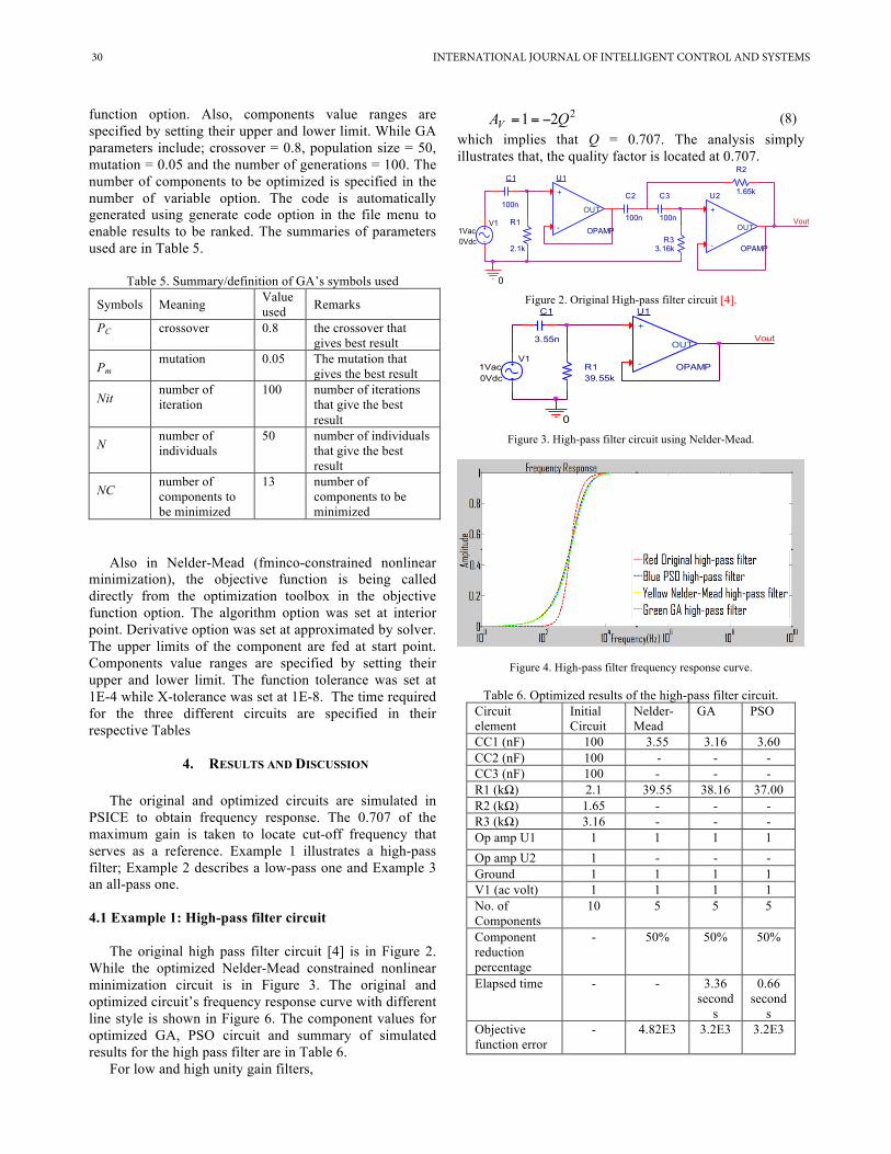
The original high pass filter circuit [4] is in Figure 2. While the optimized Nelder-Mead constrained nonlinear minimization circuit is in Figure 3. The original and optimized circuit’s frequency response curve with different line style is shown in Figure 6. The component values for optimized GA, PSO circuit and summary of simulated results for the high pass filter are in Table 6.
For low and high unity gain filters,
221 QAV −== (8) which implies that Q = 0.707. The analysis simply illustrates that, the quality factor is located at 0.707.
Figure 2. Original High-pass filter circuit [4].
Figure 3. High-pass filter circuit using Nelder-Mead.
Figure 4. High-pass filter frequency response curve.
Table 6. Optimized results of the high-pass filter circuit. Circuit element
Initial Circuit
Nelder-Mead
GA PSO
CC1 (nF) 100 3.55 3.16 3.60 CC2 (nF) 100 - - - CC3 (nF) 100 - - - R1 (kΩ) 2.1 39.55 38.16 37.00 R2 (kΩ) 1.65 - - - R3 (kΩ) 3.16 - - - Op amp U1 1 1 1 1 Op amp U2 1 - - - Ground 1 1 1 1 V1 (ac volt) 1 1 1 1 No. of Components
10 5 5 5
Component reduction percentage
- 50% 50% 50%
Elapsed time - - 3.36 second
s
0.66 second
s Objective function error
- 4.82E3 3.2E3 3.2E3
U1
OPAMP
+
-
OUTV1
1Vac0Vdc
0
0V
C1
100n
R1
2.1k
U2
OPAMP
+
-
OUT
C2
100n
C3
100n
R2
1.65k
0A
R33.16k
0A0V
0V
0V0V
0V
Vout
U1
OPAMP
+
-
OUTV1
1Vac0Vdc
0
C1
3.55n
R139.55k
0A
Vout
30 INTERNATIONAL JOURNAL OF INTELLIGENT CONTROL AND SYSTEMS

4.2 Example 2: Low-pass filter circuit
The original low pass filter circuit [4] is in Figure 5. While the optimized Nelder-Mead constrained nonlinear minimization circuit is in Figure 6. The original and optimized circuit’s frequency response curve with different line style is shown in Figure 7. The component values for optimized GA, PSO circuit and summary of simulated results for the high pass filter are in Table 7.
Figure 5. Original low-pass filter circuit [4].
Figure 6. Low-pass filter circuit using Nelder-Mead circuit.
Figure 7. Low-pass filter frequency response curve.
4.3 Example 3: All pass filter
The original all pass filter circuit [4] is in Figure 8. While the optimized Nelder-Mead constrained nonlinear minimization circuit is in Figure 9. The original and optimized circuit’s frequency response curve with different line style is shown in Figure 10. The component values for optimized GA, PSO circuit and summary of simulated results for the all-pass filter are in Table 8.
Table 7. Optimized results of the low-pass filter circuit. Circuit elements
Initial Circuit
Nelder-Mead
GA PSO
CC1 (nF) 1 4.01 0.24 0.1 CC2 (pF) 820 799.01 786.66 793.55 CC3 (nF) 1.5 0.12 0.02 0.2 CC4 (pF) 330 - - - CC5 (nF) 4.7 - - - R1 (kΩ) 3.16 0.775 0.54 0.54 R2 (kΩ) 1.87 0.12 0.09 0.02 R3 (kΩ) 4.42 5.51 3.19 3 R4 (kΩ) 1.47 - - - R5 (kΩ) 4.53 - - - Ground 1 1 1 1 Op amp U1 1 1 1 1 Op amp U2 1 1 1 1 Op amp U3 1 - - - V1 (ac volt) 1 1 1 1 No. of Components
15 10 10 10
Component reduction percentage
- 33.33% 33.33% 33.33%
Elapsed time - - 4.98 seconds
0.99 seconds
Objective function error
- 843.03 792.03 792.03
Figure 8. Original 7th order all-pass filter circuit [4].
U1
OPAMP
+
-
OUT
U2
OPAMP
+
-
OUTV11Vac0Vdc
0
U3
OPAMP
+
-
OUT
C1
1nC2
820pC4
330p
C3 1.5nC5 4.7nR1
3.16k R2
1.87k
R3
4.42k R4
1.47k
R5
4.53k Vout
U1
OPAMP
+
-
OUT
U2
OPAMP
+
-
OUTV11Vac0Vdc
0
C1
4.01nC2
799.01p
C3 0.12nR1
0.775k R2
0.12k
R3
5.51k Vout
U1
OPAMP
+
-
OUT
Vout
V11Vac0Vdc
0
U2
OPAMP
+
-
OUT
R1
1k
R4
2k
C3 1n
R2
1k
R5
1k
R3
1k
R8
1kU3
OPAMP
+
-
OUT
R7
1kR6
1k
C2
1n
C1 1n
U4
OPAMP
+
-
OUT
R9
2k
C5
1n R10
1k
R13
1kU5
OPAMP
+
-
OUT
R12
1kR11
1k
C4
1n
U6
OPAMP
+
-
OUT
R14
2k
C7
1nR15
1k
R18
1kU7
OPAMP
+
-
OUT
R17
1kR16
1k
C6
1n
INTERNATIONAL JOURNAL OF INTELLIGENT CONTROL AND SYSTEMS 31

Table 8. Optimized Results of the all-pass filter circuit. Circuit element
Initial Circuit
Nelder-Mead
GA PSO
C1 (nF) 1 1.55 1.76 1.82 C2 (nF) 1 1.55 1.52 1 C3 (nF) 1 1.55 1.52 1 C4 (nF) 1 1.55 1.58 1.09 C5 (nF) 1 1.55 1.58 1.09 C6 (nF) 1 - - - C7 (nF) 1 - - - R1(kΩ) 1 1.33 0.65 1.01 R2 (kΩ) 1 1.33 0.64 0.54 R3 (kΩ) 1 1.33 0.65 1.01 R4 (kΩ) 2 0.78 0.84 1 R5 (kΩ) 1 1.33 1.76 1.59 R6 (kΩ) 1 1.33 0.58 0.5 R7 (kΩ) 1 1.33 0.59 0.5 R8 (kΩ) 1 1.33 0.59 0.5 R9 (kΩ) 2 0.78 0.99 1 R10 (kΩ) 1 1.33 0.74 1.32 R11 (kΩ) 1 1.33 1.76 2 R12 (kΩ) 1 1.33 1.97 1.43 R13 (kΩ) 1 1.33 1.97 1.43 R14 (kΩ) 2 - - - R15 (kΩ) 1 - - - R16 (kΩ) 1 - - - R17 (kΩ) 1 - - - R18 (kΩ) 1 - - - Ground 1 1 1 1 Op amp U1 1 1 1 1 Op amp U2 1 1 1 1 Op amp U3 1 1 1 1 Op amp U4 1 1 1 1 Op amp U5 1 1 1 1 Op amp U6 1 - - - Op amp U7 1 - - - V1 (ac volt) 1 1 1 1 No. of Components
34 25 25 25
Component reduction percentage
- 26.47% 26.47% 26.47%
Elapsed time - - 18.55 seconds
4.05 seconds
Objective function error
- 3.377E5 2.188E5 2.188E5
Table 9 illustrates the frequencies of all the quality factor points. The presented results have suggested that, this approach can further reduce components in low, high and all pass filter especially in area where a phase angle change has no effect on appliance.
5. CONCLUSIONS
Operational amplifier filter circuits are optimized. In the high-pass filter circuit, third order filter is minimized by using one stage operational amplifier to obtain an equivalent result of third order that has a component count
Figure 9. All-pass filter of optimized Nelder-Mead 7th order circuit.
Figure 10. All-pass filter Frequency response curve.
Table 9. The location of Q-factor in the low, high and all pass filter for the original circuit and the optimized circuit
Circuit type
High-pass filter
Low-pass filter
All-pass filter circuit Low-pass High-pass
Original 1 kHz 33 kHz 10.30 kHz 100.5 kHz
Nilder-Mead
1.1 kHz 29 kHz 10.32 kHz 100.2 kHz
GA 1.3 kHz 34 kHz 10.31 kHz 100.3 kHz PSO 1.2 kHz 34 kHz 10.30 kHz 100.4kHz
reduction of five. In the low-pass filter circuit, a fifth order filter circuit minimized by using a three stage operational amplifier filter to obtain an equivalent result of a fifth order one that has a component count reduction of five. In the all-pass filter, a seventh order filter is minimized by using a five stage operational amplifier that has a component count reduction of nine. It implies that with a computer program, a lower order operational amplifier filter can be programmed in such a way to achieve a higher order operational amplifier filter by locating the quality factor of 0.707 with its corresponding frequency as specified by the original circuit. Also, PSO offers the best results as regard
U1
OPAMP
+
-
OUT
Vout
V11Vac0Vdc
0
U2
OPAMP
+
-
OUT
R1
1.33k
R4
0.78k
C3 1.55n
R2
1.33k
R5
1.33k
R3
1.33k
R8
1.33kU3
OPAMP
+
-
OUT
R7
1.33kR6
1.33k
C2
1.55n
C1 1.55n
U4
OPAMP
+
-
OUT
R9
0.78k
C5
1.55n R10
1.33k
R13
1.33kU5
OPAMP
+
-
OUT
R12
1.33kR11
1.33k
C4
1.55n
32 INTERNATIONAL JOURNAL OF INTELLIGENT CONTROL AND SYSTEMS

frequency response for the three examples, followed by GA while Nelder-Mead has the worst result.
ACKNOWLEDGEMENT
The first author would like to acknowledge the financial support from Tertiary Trust Fund through University of Calabar, Calabar, Nigeria. The authors also would like to thank the comments provided by the anonymous reviewers and editor, which help the authors improve this paper significantly.
REFERENCES [1] Bandler, J., Ye, S., Biernacki, R., Chen, S., and Swanson Jr, D.,
"Minimax microstrip filter design using direct EM field simulation," in Microwave Symposium Digest, 1993., IEEE MTT-S International, pp. 889-892, 1993.
[2] Barros, M., Guilherme, J., and Horta, N., "Analog circuits optimization based on evolutionary computation techniques," Integration, the VLSI Journal, vol. 43, pp. 136-155, 1, 2010.
[3] Brambilla, A., Espinosa, G., Montecchi, F., and Sánchez-Sinecio, E., "Noise optimization in operational transconductance amplifier filters," in Circuits and Systems, 1989., IEEE International Symposium on, pp. 118-1211, 989.
[4] Carter, B., and Mancini, R., "Op amps for everyone" Third Edition Newnes, 2009.
[5] Chatterjee, S., Tsividis, Y. and Kinget, P., "0.5-V analog circuit techniques and their application in OTA and filter design," Solid-State Circuits, IEEE Journal of, vol. 40, pp. 2373-2387, 2005.
[6] Coello, C. A., Christiansen, A. D., and Aguirre, A. H., "Automated design of combinational logic circuits using genetic algorithms," in Proceedings of the International Conference on Artificial Neural Nets and Genetic Algorithms, pp. 335-338, 1997.
[7] Fakhfakh, M., Cooren, Y., Loulou, M., and Siarry, P., "A Particle Swarm Optimisation technique used for the improvement of analogue circuit performances," Particle Swarm Optimization, pp. 169-182, 2009.
[8] Fakhfakh, M., Cooren, Y., Sallem, A., Loulou, M., and Siarry, P., "Analog circuit design optimisation through the particle swarm optimisation technique," Analogue Integr. Cir. Signal Proc., vol. 63, pp. 71-82, 2010.
[9] Gavin, H. P., "The Nelder-Mead Algorithm in Two Dimensions," CEE 201L.Duke U, 2013.
[10] Geiger, R. L., and Sanchez-Sinencio, E., "Active filter design using operational transconductance amplifiers: a tutorial," Circuits and Devices Magazine, IEEE, vol. 1, pp. 20-32, 1985.
[11] Golonek, T., and Rutkowski, J., "Genetic-algorithm-based method for optimal analog test point selection," IEEE Transactions on Circuits and Systems II: Express Briefs, vol. 54, pp. 117-121, 2007.
[12] Kang, Q., Zhou, M., An, J., and Wu, Q., "Swarm intelligence approaches to optimal power flow problem with distributed generator failures in power networks," Automation Science and Engineering, IEEE Transactions on, vol. 10, pp. 343-353, 2013.
[13] Karaboga, N., "A new design method based on artificial bee colony algorithm for digital IIR filters," Journal of the Franklin Institute, vol. 346, pp. 328-348, 2009.
[14] Koza, J. R., Bennett III, F. H., Andre, D., Keane, M. A., and Dunlap, F., "Automated synthesis of analogue electrical circuits by means of genetic programming," Evolutionary Computation, IEEE Transactions on, vol. 1, pp. 109-128, 1997.
[15] Koza, J. R., Bennett III, F. H., and Stiffelman, O., Genetic Programming as a Darwinian Invention Machine, Springer, 1999.
[16] Kumar, P. P., and Duraiswamy, K., "An Optimised Device Sizing of Analog Circuits using Particle Swarm Optimisation," Journal of Computer Science, vol. 8, pp. 930, 2012.
[17] Lagarias, J. C., Reeds, J. A., Wright, M. H., and Wright, P. E., "Convergence properties of the Nelder--Mead simplex method in low dimensions," SIAM Journal on Optimization, vol. 9, pp. 112-147, 1998.
[18] Liang, X., Li, W., Zhang, Y., and Zhou, M., "An adaptive particle swarm optimization method based on clustering," Soft Computing, pp. 1-18, 2014.
[19] Liu, B., Wang, Y., Yu, Z., Liu, L., Li, M., Wang, Z., Lu, J., and Fernández, F. V., "Analog circuit optimization system based on hybrid evolutionary algorithms," INTEGRATION, the VLSI Journal, vol. 42, pp. 137-148, 2009.
[20] Lohn, J. D., and Colombano, S. P., "A circuit representation technique for automated circuit design," Evolutionary Computation, IEEE Transactions on, vol. 3, pp. 205-219, 1999.
[21] Lohn, J. D., and Colombano, S. P., "Automated analogue circuit synthesis using a linear representation," in Evolvable Systems: From Biology to Hardware from nasa.gov Springer, pp. 125-133, 1998.
[22] Louis, S. J., "Genetic learning for combinational logic design," Soft Computing, vol. 9, pp. 38-43, 2005.
[23] Manoj, V., and Elias, E., "Artificial bee colony algorithm for the design of multiplier-less nonuniform filter bank transmultiplexer," Inf. Sci, vol. 192, pp. 193-203, 2012.
[24] Miller, J. F., Job, D., and Vassilev, V. K., "Principles in the evolutionary design of digital circuits—Part I," Genetic Programming and Evolvable Machines, vol. 1, pp. 7-35, 2000.
[25] Moraglio, A., and Johnson, C. G., "Geometric generalization of the nelder-mead algorithm," in Evolutionary Computation in Combinatorial Optimization Anonymous Springer, pp. 190-201, 2010.
[26] Nelder, J. A., and Mead, R., "A simplex method for function minimization," The Computer Journal, vol. 7, pp. 308-313, 1965.
[27] O'Dare, M., and Arslan, T., "Generating test patterns for VLSI circuits using a genetic algorithm," Electron. Lett., vol. 30, pp. 778-779, 1994.
[28] Park, J., Kim, C., Kim, J., Park, J., Qian, Y., Ahn, D., and Itoh, T., "Modeling of a photonic bandgap and its application for the low-pass filter design," in Microwave Conference, 1999 Asia Pacific, pp. 331-334, 1999.
[29] Razavi, B., "Fundamentals of Microelectronics" John Willy and Sons, NJ. 2008.
[30] Sönmez, Ö. S., and Dündar, G., "Simulation-based analog and RF circuit synthesis using a modified evolutionary strategies algorithm," Integration, the VLSI Journal, vol. 44, pp. 144-154, 3, 2011.
[31] Sripramong, T., and Toumazou, C., "The invention of CMOS amplifiers using genetic programming and current-flow analysis," Computer-Aided Design of Integrated Circuits and Systems, IEEE Transactions on, vol. 21, pp. 1237-1252, 2002.
[32] Trelea, I. C., "The particle swarm optimisation algorithm: convergence analysis and parameter selection," Information Processing Letters, 85, 6, 317-325, Elsevier, 2003.
[33] Ulker, S., "Broadband Microwave Amplifier Design Using Particle swarm optimisation," Journal of Computers, vol. 11, pp. 2272-2276, 2011.
[34] Ulker, S., "Design of Low Noise Microwave Amplifiers Using Particle Swarm Optimisation," International Journal of Artificial Intelligence & Applications, vol. 3, 2012.
[35] Ushie, J. O. and Abbod, F. M., ''Intelligent Optimization Methods for Analogue Electronic Circuits: GA and PSO Case Study," International Conference on Machine Learning, Electrical and Mechanical Engineering (ICMLEME'2014), on Jan. 8-9, 2014 Dubai (UAE), pp. 193-199, 2014.
[36] Wang, S., Hwang, Y., Yan,S., and Chen, J., "A new CMOS wideband low noise amplifier with gain control," Integration, the VLSI Journal, vol. 44, pp. 136-143, 2011.
[37] Wojcikowski, M., Glinianowicz, J., and Bialko, M., "System for optimisation of electronic circuits using genetic algorithm," in Electronics, Circuits, and Systems, 1996. ICECS'96, Proceedings of the Third IEEE International Conference, pp. 247-250, 1996.
[38] Wright, M. H., "Nelder, Mead, and the other simplex method," Documenta Mathematica, 2010.
[39] Yang, X., Nature-Inspired Optimization Algorithms. Elsevier, 2014. [40] Zebulum, R. S., Pacheco, M. A., and Vellasco, M., "Comparison of
different evolutionary methodologies applied to electronic filter design," in Evolutionary Computation Proceedings, 1998. IEEE
INTERNATIONAL JOURNAL OF INTELLIGENT CONTROL AND SYSTEMS 33

World Congress on Computational Intelligence, the 1998 IEEE International Conference on, pp. 434-439, 1998.
[41] Zhang, J., Shi, Y., and Zhan, Z., "Power electronic circuits design: A particle swarm optimisation approach," in Simulated Evolution and Learning, 7th International Conference, Melbourne, Australia, Springer, pp 605-614, 2008.
[42] Zhang, L., and Liu, Z., "Directly performance-constrained template-based layout retargeting and optimization for analog integrated circuits," Integration, the VLSI Journal, vol. 44, pp. 1-11, 1, 2011.
[43] Zhang, Z., "Design of cosine modulated filter banks using iterative Lagrange multiplier method in Microwave," Antenna, Propagation and EMC Technologies for Wireless Communications MAPE 2005. IEEE International Symposium, pp. 157-160, 2005
[44] Zhou, L., Shi, Y., Li, Y., and Zhang, W., "Parameter selection, analysis and evaluation of an improved particle swarm optimiser with leadership," Artif. Intell. Rev., vol. 34, pp. 343-367, 2010.
Ogri J. Ushie received a B. Eng. in 2002 and MEng in 2008 in Electrical Electronics Engineering from Federal University of Technology-Yola and Abubakar Tafawa Belewa University-Bauchi both in Nigeria respectively. He is currently a PhD research student (Electrical Engineering and Electronics Research) at Brunel University London. He is a
lecturer at the University of Calabar, Calabar-Nigeria. He teaches courses in Electronics and Computer Technology in the same University. He is also a graduate student member of IEEE. He is a Cooperate member Nigerian Society of Engineers and a registered Engineer with Council for the Regulation of Engineering in Nigeria. His research interest is in area of ‘Intelligence Optimisation of Analog Electronic Circuit using Machine Learning.’
Dr Maysam F. Abbod received the BSc degree in electrical engineering from the Baghdad University of Technology, Baghdad, Iraq, in 1987, and the PhD degree in Control Engineering from the University of Sheffield, Sheffield, UK in 1992. He is currently a reader in Intelligent Systems at the College of Engineering, Design, and Physical Sciences,
Brunel University London, Uxbridge, London UK. His main research interests are intelligent systems for modelling, control and optimization. Dr Abbod is a member of IET and a UK Chartered Engineer.
Dr Evans C. Ashigwuike received a B. Eng. (Hons) and M. Eng. from the department of Electrical Electronics Engineering, Nnamdi Azikiwe University, Nigeria in 1999 and 2005, respectively. He worked as a lecturer in the department of Electrical/Electronic Engineering at the University of Abuja, Nigeria between 2005 and 2011. He just completed his PhD at Brunel University London. Dr Evans’s
research interests are in area of Computer Modelling, Electromagnetic sensors for NDT, Ultrasonic signal processing and Long Range Ultrasonic Testing.
Sagir Lawan was born in Gumel, Nigeria, in 1962. He received B. S. degree in electronics/electrical engineering and the M.S. degree in telecommunication and electronic engineering from Obafemi Awolowo University Ile-Ife in 1998 and 2010 respectively. He is currently a candidate for PhD degree in electronic and computer engineering, Brunel University London. His
research interests include image processing, temporal error concealment, and multi-view video coding.
34 INTERNATIONAL JOURNAL OF INTELLIGENT CONTROL AND SYSTEMS