Consolidated* 13900 Series
38
BHGE Data Classification: Public Consolidated* 13900 Series Pilot Operated Safety Relief Valve Maintenance Manual (Rev.B) Maintenance Manual Rev. B – 09/2018
Transcript of Consolidated* 13900 Series

BHGE Data Classification: Public
Consolidated*13900 Series Pilot Operated Safety Relief Valve
Maintenance Manual (Rev.B)
Maintenance ManualRev. B – 09/2018

ii | BHGE © 2018 Baker Hughes, a GE company. All rights reserved.
THESE INSTRUCTIONS PROVIDE THE CUSTOMER/OPERATOR WITH IMPORTANT PROJECT-SPECIFIC REFERENCE INFORMATION IN ADDITION TO THE CUSTOMER/OPERATOR’S NORMAL OPERATION AND MAINTENANCE PROCEDURES. SINCE OPERATION AND MAINTENANCE PHILOSOPHIES VARY, BHGE (BAKER HUGHES, A GE COMPANY) DOES NOT ATTEMPT TO DICTATE SPECIFIC PROCEDURES, BUT TO PROVIDE BASIC LIMITATIONS AND REQUIREMENTS CREATED BY THE TYPE OF EQUIPMENT PROVIDED.
THESE INSTRUCTIONS ASSUME THAT OPERATORS ALREADY HAVE A GENERAL UNDERSTANDING OF THE REQUIREMENTS FOR SAFE OPERATION OF MECHANICAL AND ELECTRICAL EQUIPMENT IN POTENTIALLY HAZARDOUS ENVIRONMENTS. THEREFORE, THESE INSTRUCTIONS SHOULD BE INTERPRETED AND APPLIED IN CONJUNCTION WITH THE SAFETY RULES AND REGULATIONS APPLICABLE AT THE SITE AND THE PARTICULAR REQUIREMENTS FOR OPERATION OF OTHER EQUIPMENT AT THE SITE.
THESE INSTRUCTIONS DO NOT PURPORT TO COVER ALL DETAILS OR VARIATIONS IN EQUIPMENT NOR TO PROVIDE FOR EVERY POSSIBLE CONTINGENCY TO BE MET IN CONNECTION WITH INSTALLATION, OPERATION OR MAINTENANCE. SHOULD FURTHER INFORMATION BE DESIRED OR SHOULD PARTICULAR PROBLEMS ARISE WHICH ARE NOT COVERED SUFFICIENTLY FOR THE CUSTOMER/OPERATOR'S PURPOSES THE MATTER SHOULD BE REFERRED TO BHGE.
THE RIGHTS, OBLIGATIONS AND LIABILITIES OF BHGE AND THE CUSTOMER/OPERATOR ARE STRICTLY LIMITED TO THOSE EXPRESSLY PROVIDED IN THE CONTRACT RELATING TO THE SUPPLY OF THE EQUIPMENT. NO ADDITIONAL REPRESENTATIONS OR WARRANTIES BY BHGE REGARDING THE EQUIPMENT OR ITS USE ARE GIVEN OR IMPLIED BY THE ISSUE OF THESE INSTRUCTIONS.
THESE INSTRUCTIONS ARE FURNISHED TO THE CUSTOMER/OPERATOR SOLELY TO ASSIST IN THE INSTALLATION, TESTING, OPERATION, AND/OR MAINTENANCE OF THE EQUIPMENT DESCRIBED. THIS DOCUMENT SHALL NOT BE REPRODUCED IN WHOLE OR IN PART WITHOUT THE WRITTEN APPROVAL OF BHGE.
Consolidated 13900 Series POSRV Maintenance Manual | iii© 2018 Baker Hughes, a GE company. All rights reserved.
NOTICE!
For valve configurations not listed in this manual, please contact your local Consolidated Green Tag* Center for assistance.
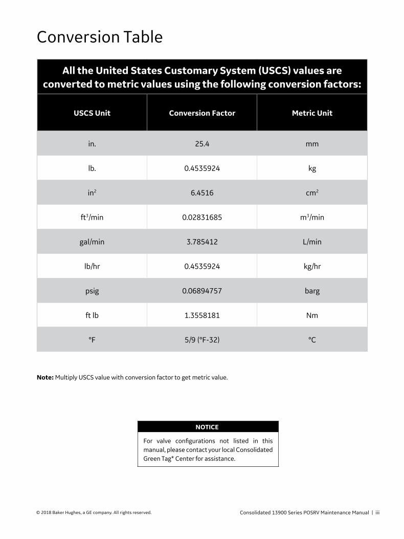
All the United States Customary System (USCS) values are converted to metric values using the following conversion factors:
USCS Unit Conversion Factor Metric Unit
in. 25.4 mm
lb. 0.4535924 kg
in2 6.4516 cm2
ft3/min 0.02831685 m3/min
gal/min 3.785412 L/min
lb/hr 0.4535924 kg/hr
psig 0.06894757 barg
ft lb 1.3558181 Nm
°F 5/9 (°F-32) °C
Conversion Table
Note: Multiply USCS value with conversion factor to get metric value.
iv | BHGE © 2018 Baker Hughes, a GE company. All rights reserved.
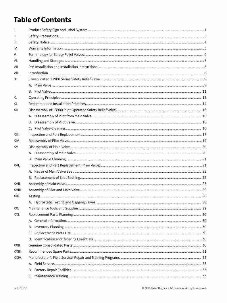
I. Product Safety Sign and Label System ............................................................................................................................................................ 1
II. Safety Precautions. .................................................................................................................................................................................................. 2
III. Safety Notice............................................................................................................................................................................................................... 4
IV. Warranty Information ............................................................................................................................................................................................ 5
V. Terminology for Safety Relief Valves ................................................................................................................................................................ 6
VI. Handling and Storage .............................................................................................................................................................................................. 7
VII Pre-Installation and Installation Instructions .............................................................................................................................................. 8
VIII. Introduction ................................................................................................................................................................................................................. 8
IX. Consolidated 13900 Series Safety Relief Valve ........................................................................................................................................... 9
A. Main Valve ............................................................................................................................................................................................................ 9
B. Pilot Valve ......................................................................................................................................................................................................... 11
X. Operating Principles ............................................................................................................................................................................................ 12
XI. Recommended Installation Practices .......................................................................................................................................................... 14
XII. Disassembly of 13900 Pilot Operated Safety Relief Valve .................................................................................................................. 16
A. Disassembly of Pilot from Main Valve ................................................................................................................................................. 16
B. Disassembly of Pilot Valve ......................................................................................................................................................................... 16
C. Pilot Valve Cleaning ...................................................................................................................................................................................... 16
XIII. Inspection and Part Replacement .................................................................................................................................................................. 17
XIV. Reassembly of Pilot Valve ................................................................................................................................................................................... 19
XV. Disassembly of Main Valve ................................................................................................................................................................................. 20
A. Disassembly of Main Valve ....................................................................................................................................................................... 20
B. Main Valve Cleaning ..................................................................................................................................................................................... 21
XVI. Inspection and Part Replacement (Main Valve) ........................................................................................................................................ 21
A. Repair of Main Valve Seat ......................................................................................................................................................................... 22
B. Replacement of Seat Bushing .................................................................................................................................................................. 22
XVII. Assembly of Main Valve ...................................................................................................................................................................................... 23
XVIII. Assembly of Pilot and Main Valve .................................................................................................................................................................. 25
XIX. Testing ....................................................................................................................................................................................................................... 26
A. Hydrostatic Testing and Gagging Valves ............................................................................................................................................ 28
XX. Maintenance Tools and Supplies .................................................................................................................................................................... 29
XXI. Replacement Parts Planning ............................................................................................................................................................................ 30
A. General Information ..................................................................................................................................................................................... 30
B. Inventory Planning ........................................................................................................................................................................................ 30
C. Replacement Parts List .............................................................................................................................................................................. 30
D. Identification and Ordering Essentials................................................................................................................................................. 30
XXII. Genuine Consolidated Parts ............................................................................................................................................................................ 30
XXIII. Recommended Spare Parts .............................................................................................................................................................................. 31
XXIV. Manufacturer’s Field Service, Repair and Training Programs............................................................................................................. 33
A. Field Service ..................................................................................................................................................................................................... 33
B. Factory Repair Facilities ............................................................................................................................................................................. 33
C. Maintenance Training .................................................................................................................................................................................. 33
Table of Contents

Consolidated 13900 Series POSRV Maintenance Manual | 1© 2018 Baker Hughes, a GE company. All rights reserved.
DANGER — Immediate hazards which WILL result in severe personal injury or death.
WARNING — Hazards or unsafe practices which COULD result in severe personal injury or death.
CAUTION — Hazards or unsafe practices which COULD result in minor personal injury.
ATTENTION — Hazards or unsafe practices which COULD result in product or property damage
If and when required, appropriate safety labels have been included in the rectangular margin blocks throughout this manual. Safety labels are vertically oriented rectangles as shown in the representative examples (below), consisting of three panels encircled by a narrow border. The panels can contain four messages which communicate:
• The level of hazard seriousness.
• The nature of the hazard.
• The consequence of human, or product, interaction with the hazard.
• The instructions, if necessary, on how to avoid the hazard.
The top panel of the format contains a signal word (DANGER, WARNING, CAUTION or ATTENTION) which communicates the level of hazard seriousness.
The center panel contains a pictorial which communicates the nature of the hazard, and the possible consequence of human or product interaction with the hazard. In some instances of human hazards the pictorial may, instead, depict what preventive measures to take, such as wearing protective equipment.
The bottom panel may contain an instruction message on how to avoid the hazard. In the case of human hazard, this message may also contain a more precise definition of the hazard, and the consequences of human interaction with the hazard, than can be communicated solely by the pictorial.
I. Product Safety Sign and Label System
Do not remove bolts if pressure in line, as this
will result in severe personal injury or death.
Know all valve exhaust/leakage points to avoid
possible severe personal injury or death.
Wear necessary protective equipment to prevent possible injury.
Handle valve carefully. Do not drop or strike.
1
2
3
4
1 2 3 4
2 | BHGE © 2018 Baker Hughes, a GE company. All rights reserved.
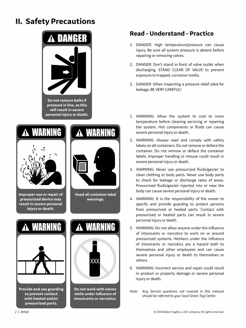
II. Safety Precautions
Improper use or repair of pressurized device may
result in severe personal injury or death.
Heed all container label warnings.
1. DANGER: High temperature/pressure can cause injury. Be sure all system pressure is absent before repairing or removing valves.
2. DANGER: Don’t stand in front of valve outlet when discharging. STAND CLEAR OF VALVE to prevent exposure to trapped, corrosive media.
3. DANGER: When inspecting a pressure relief valve for leakage. BE VERY CAREFUL!
1. WARNING: Allow the system to cool to room temperature before cleaning servicing or repairing the system. Hot components or fluids can cause severe personal injury or death.
2. WARNING: Always read and comply with safety labels on all containers. Do not remove or deface the container. Do not remove or deface the container labels. Improper handling or misuse could result in severe personal injury or death.
3. WARNING: Never use pressurized fluids/gas/air to clean clothing or body parts. Never use body parts to check for leakage or discharge rates of areas. Pressurized fluids/gas/air injected into or near the body can cause severe personal injury or death.
4. WARNING: It is the responsibility of the owner to specify and provide guarding to protect persons from pressurized or heated parts. Contact with pressurized or heated parts can result in severe personal injury or death.
5. WARNING: Do not allow anyone under the influence of intoxicants or narcotics to work on or around pressurized systems. Workers under the influence of intoxicants or narcotics are a hazard both to themselves and other employees and can cause severe personal injury or death to themselves or others.
6. WARNING: Incorrect service and repair could result in product or property damage or severe personal injury or death.
Do not remove bolts if pressure in line, as this
will result in severe personal injury or death.
Note: Any Service questions not covered in this manual should be referred to your local Green Tag Center.
Read - Understand - Practice
XXX
Provide and use guarding to prevent contact with heated and/or pressurized parts.
Do not work with valves while under influence of intoxicants or narcotics.

Consolidated 13900 Series POSRV Maintenance Manual | 3© 2018 Baker Hughes, a GE company. All rights reserved.
II. Safety Precautions (Contd.)
Improper tools or improper use of right tools
could result in personal injury or product damage.
All potential hazards may not be covered in
this manual.
Heed all service manual warnings. Read installation
instructions before installing valve(s).
Wear necessary protective equipment to prevent possible injury.
Know nuclear "health physics" procedures, if applicable, to avoid
possible severe personal injury or death.
7. WARNING: This valve product line is not intended for radioactive nuclear applications. Some valve products manufactured by BHGE may be used in radioactive environments. Consequently, prior to starting any operation in a radioactive environment, the proper “health physics” procedures should be followed, if applicable.
8. WARNING: Use of improper tools or improper use of right tools could result in personal injury or product or property damage.
9. WARNING: These WARNINGS are as complete as possible but not all-inclusive. BHGE cannot know all conceivable service methods nor evaluate all potential hazards.
Always use appropriate restoration procedures.
1. CAUTION: Heed all service manual warnings. Read installation instructions before installing valve(s).
2. CAUTION: Wear hearing protection when testing or operating valves.
3. CAUTION: Wear appropriate eye and clothing protection.
4. CAUTION: Wear protective breathing apparatus to protect against toxic media.
Note: Any Service questions not covered in this manual should be referred to your local Green Tag Center.
Cautions Concerning Product Warning Labels
Appropriate service and repair important to safe, reliable operation of all valve products. Restoration to original quality and manufacturing specifications will accomplish the desired results. Procedures developed by BHGE as described in the applicable installation and Maintenance Manual, when correctly applied, will be effective.
Restoring Safety

4 | BHGE © 2018 Baker Hughes, a GE company. All rights reserved.
III. Safety NoticeProper installation and start-up is essential to the safe and reliable operation of all valve products. The relevant procedures recommended by BHGE, and described in these instructions, are effective methods of performing the required tasks.
It is important to note that these instructions contain various “safety messages” which should be carefully read in order to minimize the risk of personal injury, or the possibility that improper procedures will be followed which may damage the involved BHGE product, or render it unsafe. It is also important to understand that these “safety messages” are not exhaustive. BHGE can not possibly know, evaluate, and advise any customer of all of the conceivable ways in which tasks might be performed, or of the possible hazardous consequences of each way. Consequently, BHGE has not undertaken any such broad evaluation and, thus, anyone who uses a procedure and/or tool, which is not recommended by BHGE, or deviates from BHGE recommendations, must be thoroughly satisfied that neither personal safety, nor valve safety, will be jeopardized by the method and/or tools selected. Contact your local Green Tag Center if there are any questions relative to tools/methods.
The installation and start-up of valves and/or valve products may involve proximity to fluids at extremely high pressure and/or temperature. Consequently, every precaution should be taken to prevent injury to personnel during the performance of any procedure. These precautions should consist of, but are not limited to, ear drum protection, eye protection, and the use of protective clothing, (i.e., gloves, etc.) when personnel are in, or around, a valve work area. Due to the various circumstances and conditions in which these operations may be performed on BHGE products, and the possible hazardous consequences of each way, BHGE can not possibly evaluate all conditions that might injure personnel or equipment. Nevertheless, BHGE does offer certain Safety Precautions, listed in Section II, for customer information only.
It is the responsibility of the purchaser or user of BHGE valves/equipment to adequately train all personnel who will be working with the involved valves/equipment. For more information on training schedules, please contact your local Green Tag Center. Further, prior to working with the involved valves/equipment, personnel who are to perform such work should become thoroughly familiar with the contents of these instructions.
Wear necessary protective equipment to prevent possible injury

Consolidated 13900 Series POSRV Maintenance Manual | 5© 2018 Baker Hughes, a GE company. All rights reserved.
IV. Warranty InformationWarranty Statement
Warranty Statement1: BHGE warrants that its products and work will meet all applicable specifications and other specific product and work requirements (including those of performance), if any, and will be free from defects in material and workmanship.
CAUTION: Defective and nonconforming items must be held for BHGE inspection and returned to the manufacturer upon request.
Incorrect Selection or Misapplication of Products: BHGE cannot be responsible for customer’s incorrect selection or misapplication of our products.
Unauthorized Repair Work: BHGE has not authorized any non-BHGE affiliated repair companies, contractors or individuals to perform warranty repair service on new products or field repaired products of its manufacture. Therefore customers contracting such repair services from unauthorized sources must do so at their own risk.
Unauthorized Removal of Seals: All new valves and valves repaired in the field by BHGE Field Service are sealed to assure the customer of our guarantee against defective workmanship. Unauthorized removal and/or breakage of this seal will negate our warranty.
(1) Refer to BHGE’s Standard Terms of Sale for complete details on warranty and limitation of remedy and liability.
Defective and nonconforming items
must be inspected by BHGE.
S E A L E D
Removal and/or breakage of seal will negate our warranty.

6 | BHGE © 2018 Baker Hughes, a GE company. All rights reserved.
V. Terminology for Safety Relief Valves• Accumulation: The pressure increase over the maximum
allowable working pressure of the vessel during discharge through the POSRV, expressed as a percentage of that pressure or in actual pressure units.
• Backpressure: The pressure on the discharge side of the POSRV:
� Built-up Backpressure: Pressure that develops at the valve outlet as a result of flow, after the POSRV has been opened.
� Superimposed Backpressure: Pressure in the discharge header before the POSRV opens.
� Constant Backpressure: Superimposed backpressure that is constant with time.
� Variable Backpressure: Superimposed backpressure that will vary with time.
• Blowdown: The difference between set pressure and reseating pressure of the POSRV, expressed as a percentage of the set pressure or in actual pressure units.
• Cold Differential Set Pressure: The pressure at which the valve is adjusted to open on the test stand. This pressure corrects for backpressure when a pop action pilot’s vent is piped to the main valve outlet.
• Differential Between Operating and Set Pressures: Valves in process service will generally give best results if the operating pressure does not exceed 90% of the set pressure. However, on pump and compressor discharge lines, the differential required between the operating and set pressures may be greater because of pressure pulsations coming from a reciprocating piston. The valve should be set as far above the operating pressure as possible.
• Lift: The actual travel of the disc away from the closed position when a valve is relieving.
• Maximum Allowable Working Pressure: The maximum gauge pressure permissible in a vessel at a designated temperature. A vessel may not be operated above this pressure or its equivalent at any metal temperature other than that used in its design. Consequently, for that metal temperature, it is the highest pressure at which the primary pressure POSRV is set to open.
• Operating Pressure: The gauge pressure to which the vessel is normally subjected in service. A suitable margin is provided between operating pressure and maximum
allowable working pressure. For assured safe operation, the operating pressure should be at least 10% under the maximum allowable working pressure or 5 psig (0.34 bar), whichever is greater.
• Overpressure: A pressure increase over the set pressure of the primary relieving device. Overpressure is similar to accumulation when the relieving device is set at the maximum allowable working pressure of the vessel. Normally, overpressure is expressed as a percentage of set pressure.
• Pilot Operated Safety Relief Valve (POSRV): A pressure relief valve in which the major relieving device is combined with, and is controlled by, a self-actuated auxiliary pressure relief valve.
• Rated Capacity: The percentage of measured flow at an authorized percent overpressure permitted by the applicable code. Rated capacity is generally expressed in pounds per hour (lb/hr) or kilograms per hour (kg/hr) for vapors, standard cubic feet per minute (SCFM) or cubic meters per minute (m3/min) for gases, and in gallons per minute (GPM) or Liter/min (L/min) for liquids.
• Relief Valve: An automatic pressure-relieving device, actuated by static pressure upstream from the valve. A relief valve is used primarily for liquid service.
• Safety Relief Valve (SRV): An automatic pressure-relieving device used as either a safety or relief valve, depending upon application. The SRV is used to protect personnel and equipment by preventing excessive overpressure.
• Safety Valve: An automatic pressure-relieving device actuated by the static pressure upstream of the valve, and characterized by a rapid opening or “pop” action. It is used for steam, gas, or vapor service.
• Set Pressure: The gauge pressure at the valve inlet, for which the relief valve has been adjusted to open under service conditions. In liquid service, the inlet pressure at which the valve starts to discharge determines set pressure. In gas or vapor service, the inlet pressure at which the valve pops determines the set pressure.

Consolidated 13900 Series POSRV Maintenance Manual | 7© 2018 Baker Hughes, a GE company. All rights reserved.
1. The valve, either crated or uncrated, should always be kept with the inlet flange down, i.e., never laid on its side, to prevent possible misalignment and damage to internals.
2. Pressure relief valves should be stored in a dry environment to protect them from the weather. They should not be removed from the skids or crates until immediately prior to installation.
3. Flange protectors and sealing plugs should not be removed until the valve is ready to be bolted on to the installation.
4. Pressure relief valves, either crated or uncrated, should never be subjected to sharp impact. This would be most likely to occur by bumping or dropping during loading or unloading from a truck or while moving with a power conveyor, such as a fork lift truck. While hoisting to the installation, care should be exercised to prevent bumping the valve against steel structures and other objects.
5. Uncrated valves should be moved or hoisted by the three eye bolts located on the top flange of the valve (See Figure 1, Item 26). Crated valves should always be lifted with the inlet flange down.
6. When pressure relief valves are uncrated and the flange protectors removed immediately prior to installation, meticulous care should be exercised to prevent dirt and other foreign materials from entering the inlet and outlet ports while bolting in place.
7. "Short Term Storage" is defined as storage not exceeding six months from date of shipment. "Long Term Storage" is defined as storage not exceeding one year from date of shipment. "Extended Storage" is defined as storage exceeding one year from date of shipment.
8. For Extended Storage, items shall be stored within a fire resistant, tear resistant, envelope and stored in a weathertight, and well ventilated building or equivalent enclosure. Precautions shall be taken against vandalism.
This area shall be situated and constructed so that it will not be subject to flooding; the floor shall be paved or equal, and well drained. Items shall be placed on pallets or shoring to permit air circulation. The area shall be provided with uniform heating and temperature control or its equivalent to prevent condensation and corrosion. Minimum temperature shall be 40°F (4.4°C) and maximum temperature shall not exceed 140°F (60°C). Valves or parts shall be stored in the original shipping container. The shipping container shall be kept in an upright position as indicated by the markings on the crate. DO NOT STACK. Level B storage requirements as specified in ANSI N45.2.2 shall apply. All material, upon receipt, should be inspected and all coatings and packaging damaged during shipping and handling shall be put into like new condition before storing.
9. For Long Term Storage, items shall be stored indoors or equivalent with all provisions and requirements as set forth in extended storage items except that heat and temperature control is not required. Level C storage requirements as specified in ANSI N45.2.2 shall apply.
10. For Short Term Storage, the storage requirements are the same as those specified for Long Term Storage.
11. For any reason should it be necessary to store the valve in an uncrated condition, the valve shall be stored in an upright position on the inlet flange, making certain the inlet flange is protected from damage. Never lay the valve on its side as damage to the internals and misalignment may be incurred. The valve, when removed from the shipping container, shall have the protectors left intact to prevent entrance of foreign materials. Use all precaution to prevent the entrance of dirt and foreign material into the valve.
VI. Handling and Storage

8 | BHGE © 2018 Baker Hughes, a GE company. All rights reserved.
VIII. Introduction
Modern nuclear power plants have given rise to systems which cycle extremely large quantities of steam at relatively low pressures. This is particularly true in the reheat portion of the turbine cycle.
These requirements have exceeded the feasible limits of conventional spring loaded safety valves. In response to this requirement, the Consolidated 13900 series pilot operated safety relief valves were developed for ASME Code Section VIII service providing discharge orifice sizes up to 200 square inches with minimum overall height and weight.
The pilot senses pressure internally through the main valve eliminating the need for external pressure lines which normally are subject to mechanical damage, fouling or rupture.
The combination of conventional spring loaded pilot and an internal sensing tube meet all Code requirements for a Fail Safe Device.
As an additional safety feature, the pilot discharge can be vented to the outlet of the main valve if required. This is accomplished by the use of a discharge tube from the pilot valve outlet to the main valve outlet.
An effort has been made to provide a valve which requires a minimum of maintenance upkeep and can be actually repaired on its installation site.
Factors which contribute to minimum maintenance requirements of the Main Valve consist of:
1. No metal sliding surfaces;
2. Use of Teflon seals for good high temperature sealing characteristics.
3. Metal to metal load bearing characteristics of Consolidated's O-Ring seat seal which will not deform the seat seal anymore than required for pressure sealing.
When maintenance work is necessary, the following features offer advantages in reducing the amount of labor required:
1. All parts of the valve are top inserted.
2. It is not necessary that the valve be removed from its installation site or that the outlet piping be removed, unless the seat bushing requires rework.
3. Large diameter soft seats do not require the"Excellence of Technique" needed to get leakproof large diameter metal seats.
4. The pilot valve can be removed and be reworked and readjusted on a separate small test facility.
VII. Pre-Installation and Installation Instructions
1. Lift the valve using all three eye bolts located on the top flange (See Figure 1, Item 26). Eye bolts must be fully engaged in top flange.
CAUTIONDo not allow lifting chain or sling to exert any sideways thrust on the pilot valve or damage to pilot valve will result.

Consolidated 13900 Series POSRV Maintenance Manual | 9© 2018 Baker Hughes, a GE company. All rights reserved.
IX. Consolidated 13900 Series POSRV
1
3
2
6
7
8
13
9
56
19
23
22
24
26
20
4
11
5
9
13
14
15
16
46
57
10
12
43a
43b
43a
12
44
45
21
18
17
Figure 1: Main Valve Assembly
A. Main Valve

10 | BHGE © 2018 Baker Hughes, a GE company. All rights reserved.
IX. Consolidated 13900 Series POSRV (Contd.)Ref. No.
Nomenclature
1 Main Base
2 Seat Bushing
3 Seat Bushing Retainer Screw Jam Nut
4 Retainer Lock Ring
5 O-Ring Retainer
6 Disc Drain Plug
7 Main Disc
8 Main Guide
9 Back-up Ring
10 Seat Bushing Retainer Screw
11 O-Ring Seat Seal
12 Discharge Tube Fitting Seal
13 Guide Seal
14 Floating Washer
15 Floating Washer Retainer
16 Floating Washer Retainer Lock Ring
17 Sensing Tube Assembly
17a Upper Tube
17b Lower Tube
17c Tube Flange
18 Bonnet Gasket
19 Bonnet
20 Pilot Base
21 Pilot Base Flange
22 Base Studs
23 Base Stud Nuts
24 Eye Bolt Lock Nut
25 Pilot Bonnet Gasket
26 Eye Bolt
27 Adjusting Ring Pin
28 Adjusting Ring
29 Pilot Bonnet Assembly
29a Bonnet
29b Guide
29c Pin
30 Bottom Spring Washer
Ref. No.
Nomenclature
31 Spindle Assembly
31a Spindle
31b Spindle Collar
32 Top Spring Washer
33 Lever
34 Compression Screw Lock Nut
35 Release Nut
36 Release Lock Nut
37 Cap
38 Lever Pin
39 Cap Lock Screw
40 Compression Screw
41 Spring
42 Pilot Disc Assembly
42a Disc
42b Disc Holder
42c Disc Collar
42d Retainer Ring
43 Discharge Tube Assembly
43a Fitting
43b Discharge Tube
44 Bonnet Studs
45 Bonnet Stud Nuts
46 Main Bonnet Plug
47 Main Base Nameplate (Not Shown)
48 Pilot Base Nameplate (Not Shown)
49 Main Base Drain Plug (Not Shown)
50 Main Base Nameplate Screws (Not Shown)
51 Pilot Base Nameplate Screws (Not Shown)
52 Sensing Tube Flange Gasket
53 Adjusting Ring Pin Gasket
54 Seal (Not Shown)
55 Seal Wire (Not Shown)
56 Disc Spring (Main Valve)
57 Disc Spring Ring

Consolidated 13900 Series POSRV Maintenance Manual | 11© 2018 Baker Hughes, a GE company. All rights reserved.
IX. Consolidated 13900 Series POSRV (Contd.)
37 36
38
40
34
39
35
33
29a
32
31
41
30
29c
29b
42d
42b
42a
42c
28
27
53
25
17a
21
20
17b
52
17c
Figure 2: Pilot Valve Assembly
B. Pilot Valve

12 | BHGE © 2018 Baker Hughes, a GE company. All rights reserved.
Inlet pressure, identified as P1, enters the main valve at “A”, flows through the sensing tube “B” and through the clearance formed by the sensing tube and the floating washer on the main valve disc to pressurize chamber “C”. Additional flow occurs between the top of the sensing tube and the pilot disc, down into chamber “C” through an annular region formed by the sensing tube and pilot base. Pressure in chamber “C” will now be designated P2.
When the set pressure is reached and the pilot opens, pressure is exhausted through tube “D” into the main valve outlet “E” or is exhausted directly into the atmosphere depending on if the pilot valve outlet is equipped with a discharge tube. Flow past the pilot seat will allow the P2 pressure to exhaust and reduce to a value of approximately 58% of P1, producing a lifting force on the main disc causing it to open.
X. Operating Principles
D
E
A
B
C C
Figure 3: Valve Flow Diagram

Consolidated 13900 Series POSRV Maintenance Manual | 13© 2018 Baker Hughes, a GE company. All rights reserved.
X. Operating Principles (Contd.)Once inlet pressure P1 has dropped to an appropriate predetermined value, the pilot valve will close and steam will flow into chamber “C” and will immediately repressurize the backside of the main disc, closing the main valve.
The backside of the main valve disc exposed to chamber “C” has a larger area than the main seat producing an additional force on the main seat to maintain tightness.
DRAINDRAIN
DRAIN
FABRICATEDSTEEL DRIPPAN SHOWN
ANCHOR DISCHARGE PIPINGSOLIDLY TO BUILDING STRUCTURE
A
DRAINDRAIN
A
Figure 4: Installation Piping
Figure 5: Installation Piping
Table 1: Standard Drip Pan
Valve Seat AreaMaximum
Allowable Span (A)
in2 cm2 in. m
114 735 45 1.14
143 923 62 1.58
176 1135 55 1.40
200 1290 55 1.40

14 | BHGE © 2018 Baker Hughes, a GE company. All rights reserved.
Safety relief valve discharges should be located or piped in such a manner that the discharged fluid is carried clear of man ways. Referring to Figure 4, a drain should be provided at the low point of the discharge elbow where condensate may discharge. An open gravity drain is also supplied on the backside of the valve body casting which is below the level of the valve seat to remove condensate in the body bowl.
Exhaust piping and drain lines must be installed so that they will not impose undue stress on the safety relief valve. Stresses set up in the body from any source may cause distortion and leakage at pressures below the set point. If standard drip pans are used (see Figure 4), sufficient clearance must be provided to allow for movement of the valve due to expansion and contraction of the unit on which it is installed. If blow back around the drip pan occurs, the vent piping is inadequate and its design should be investigated.
If the valves are to exhaust through horizontal piping then the distance from the valve center line to the end of the horizontal pipe must not exceed the dimension shown in Table 1.
If discharge piping is required beyond the length limit specified in Table 1, then a length of larger diameter piping should be allowed for the expansion and contraction of the unit on which the valve is installed. If the larger discharge piping extends through a wall to the outside it must be adequately fastened to the building to prevent breaking free when the valve is blown.
Cold air blowing into the valve body through the discharge pipe can cause the valve to leak. To prevent this from happening the discharge pipe should point downwind. If this is not possible, then a 900 elbow, or a “T”, should be installed.
CAUTIONAll discharge piping shall have sufficient area to accommodate the full capacity of the safety valve without causing steam to escape backward into the drip pan.
Flexible metal hoses, if used to connect safety relief valve outlets to discharge stacks, must have sufficient length and must be designed and installed in such a manner that they will not become "solid" in any position of the valve. Better results are obtained if the hoses are installed so that they will permit movement by bending rather than by stressing and compressing along their length.
Steam flowing vertically out of the discharge elbow produces a downward reaction on the elbow, depending on the quantity of steam flowing and its velocity. In large, high capacity valves this force can equal several thousand pounds and can produce severe stresses in the valve neck. The bending stresses are determined by the amount of the reactive force, combined with the moment arm or horizontal distance between the vertical centerlines of the outlet elbow and the valve. The pilot operated 13900 Safety Relief Valve is designed so that as long as the moment arm distance from the centerline of the valve to centerline of the vent piping is held within the limits stated in Table 1, neck stresses will be within code allowable values.
When installing the valve, the inlet flange bolts should be pulled down evenly to prevent inlet flange distortion and effect a leak tight flange seal (See Figure 6 and Table 2). For outlet flanges, refer to Figure 7.
It is recommended that the valve be insulated with a minimum of 2" (50.8 mm) insulation.
XI. Recommended Installation Practices
Do not drop or strike the valve.
Prevent dirt from entering outlet or inlet port.

Consolidated 13900 Series POSRV Maintenance Manual | 15© 2018 Baker Hughes, a GE company. All rights reserved.
XI. Recommended Installation Practices (Contd.)
Table 2: Inlet Nut Torque ValueFlange Class 600 Class Flange 300 Class Flange
Areain2 cm2 in2 cm2
200 1290 114, 143, 176 735, 923, 1136
RoundTorque +10% / -0%
ft-lb N-m ft-lb N-m
1 25 33.9 25 33.92 75 101.7 75 101.73 150 203.4 150 203.44 300 406.7 300 406.75 500 677.9 500 677.96 800 1084.7 - -7 1100 1491.4 - -
11 137
19
11
23
22
10
18
6
162148
20
12
24
3
21
9
17
515
4
Figure 6: Inlet Nut Torquing Sequence
1. Refer to table for torque valve for applicable round.
2. Torque each nut in sequence shown.
3. Repeat for each round.
Table 3: Outlet Nut TorqueBolts Diameter 1-1/8” (28.58 mm) Diameter Bolts 1-1/4” (31.75 mm) Diameter Bolts
RoundTorque +10% / -0%
ft-lb. N-m ft-lb. N-m
1 25 33.9 25 33.9
2 75 101.7 100 135.6
3 150 203.4 300 406.7
4 355 481.3 500 677.9
116
6
10
4
14
8
12215
5
9
3
3
7
11
1 166
18
10
4
14
8
20
12215
5
17
9
3
13
7
19
11
Figure 7: Outlet Nut Torquing Sequence
Note: For 150 Class inlets, use bolting torques for 1-1/8” (28.58 mm) diameter bolts and Figure 7a
Figure 7a: 1-1/8” (28.58 mm) Diameter Bolts
Figure 7b: 1-1/4” (31.75 mm) Diameter Bolts
16 | BHGE © 2018 Baker Hughes, a GE company. All rights reserved.
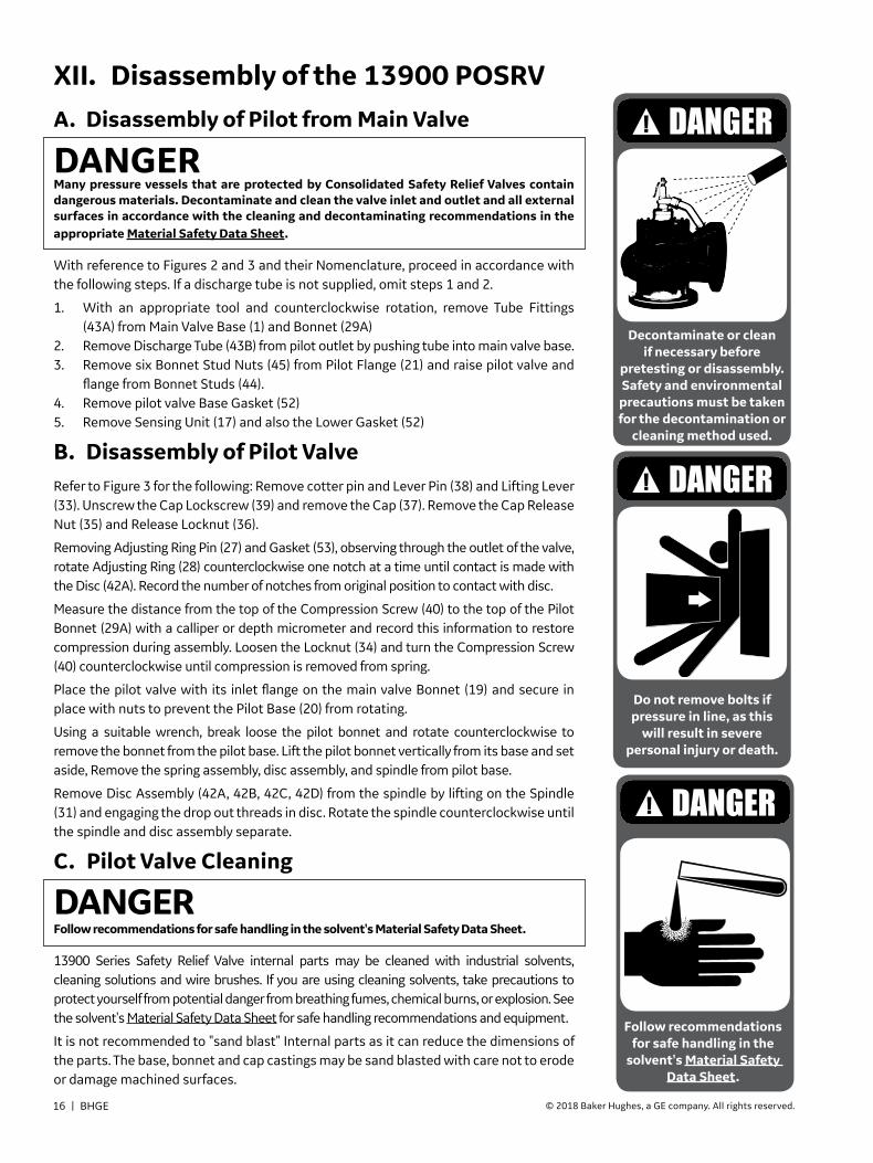
XII. Disassembly of the 13900 POSRVA. Disassembly of Pilot from Main Valve
DANGERMany pressure vessels that are protected by Consolidated Safety Relief Valves contain dangerous materials. Decontaminate and clean the valve inlet and outlet and all external surfaces in accordance with the cleaning and decontaminating recommendations in the appropriate Material Safety Data Sheet.
With reference to Figures 2 and 3 and their Nomenclature, proceed in accordance with the following steps. If a discharge tube is not supplied, omit steps 1 and 2.
1. With an appropriate tool and counterclockwise rotation, remove Tube Fittings (43A) from Main Valve Base (1) and Bonnet (29A)
2. Remove Discharge Tube (43B) from pilot outlet by pushing tube into main valve base.3. Remove six Bonnet Stud Nuts (45) from Pilot Flange (21) and raise pilot valve and
flange from Bonnet Studs (44).4. Remove pilot valve Base Gasket (52)5. Remove Sensing Unit (17) and also the Lower Gasket (52)
B. Disassembly of Pilot ValveRefer to Figure 3 for the following: Remove cotter pin and Lever Pin (38) and Lifting Lever (33). Unscrew the Cap Lockscrew (39) and remove the Cap (37). Remove the Cap Release Nut (35) and Release Locknut (36).
Removing Adjusting Ring Pin (27) and Gasket (53), observing through the outlet of the valve, rotate Adjusting Ring (28) counterclockwise one notch at a time until contact is made with the Disc (42A). Record the number of notches from original position to contact with disc.
Measure the distance from the top of the Compression Screw (40) to the top of the Pilot Bonnet (29A) with a calliper or depth micrometer and record this information to restore compression during assembly. Loosen the Locknut (34) and turn the Compression Screw (40) counterclockwise until compression is removed from spring.
Place the pilot valve with its inlet flange on the main valve Bonnet (19) and secure in place with nuts to prevent the Pilot Base (20) from rotating.
Using a suitable wrench, break loose the pilot bonnet and rotate counterclockwise to remove the bonnet from the pilot base. Lift the pilot bonnet vertically from its base and set aside, Remove the spring assembly, disc assembly, and spindle from pilot base.
Remove Disc Assembly (42A, 42B, 42C, 42D) from the spindle by lifting on the Spindle (31) and engaging the drop out threads in disc. Rotate the spindle counterclockwise until the spindle and disc assembly separate.
C. Pilot Valve Cleaning
DANGER Follow recommendations for safe handling in the solvent's Material Safety Data Sheet.
13900 Series Safety Relief Valve internal parts may be cleaned with industrial solvents, cleaning solutions and wire brushes. If you are using cleaning solvents, take precautions to protect yourself from potential danger from breathing fumes, chemical burns, or explosion. See the solvent's Material Safety Data Sheet for safe handling recommendations and equipment.
It is not recommended to "sand blast" Internal parts as it can reduce the dimensions of the parts. The base, bonnet and cap castings may be sand blasted with care not to erode or damage machined surfaces.
Do not remove bolts if pressure in line, as this
will result in severe personal injury or death.
Decontaminate or clean if necessary before
pretesting or disassembly. Safety and environmental
precautions must be taken for the decontamination or
cleaning method used.
Follow recommendations for safe handling in the
solvent's Material Safety Data Sheet.

Consolidated 13900 Series POSRV Maintenance Manual | 17© 2018 Baker Hughes, a GE company. All rights reserved.
Reconditioning of the seat surface of the disc and base is accomplished by lapping with a flat cast iron ring lap coated with Grade No. 1000 KWIK-AK-SHUN Silicon-Carbide compound, or equivalent. A 2.125" (54 mm) diameter lap should be used.
To recondition the disc seal by lapping, it is necessary to disassemble the disc assembly. This is done in the following manner: referring to Figure 8 and Table 4, the disc is contained in the disc holder by a Truarc retaining ring. The ring may be removed using a Truarc Plier, BHGE Part No. 5153302, after removing the Truarc ring, the disc collar can be removed from the disc holder.
Lapping a flat seal is simple. No special skill is required and the technique is readily apparent after a few minutes of actual lapping.
The following precautions and hints will enable anyone to do a professional job of lapping seats.
1. Keep the work clean.
2. Always use a fresh lap. If Signs of wearing (out of flatness) are evident, recondition the lap.
3. Apply a very thin layer of compound to the lap. This will prevent rounding off the edges of the seat.
4. Keep the lap squarely on the flat seat and avoid any tendency to rock the lap which will cause rounding of the seat.
5. When lapping, keep a firm grip on the lap to prevent the possibility of dropping it and damaging the seat.
6. Lap, using a reciprocating motion in all directions, at the same time applying light uniform pressure and rotating the lap slowly.
7. Replace the compound frequently after wiping off the old compound, and apply more pressure to speed the cutting action of the compound.
8. To check the seating surfaces, remove all compound from both the seat and the lap. Then shine up the seat
with the same lap using the lapping motion described above. Low sections on the seating surface will show up as a shadow in contrast to the shiny portion. If shadows are present, further lapping is necessary, and only laps known to be flat should be used. Only a few minutes will be required to remove the shadows.
9. When the lapping is completed, any lines appearing as cross scratches can be removed by rotating the lap, which has been wiped clean of compound, on the seat about its own axis.
10. The seat should now be thoroughly cleaned with alcohol, using a lint-free cloth or tissue paper.
11. When the seats cannot be repaired by lapping, they can be machined in accordance with the following instructions. Refer to Figures 8 to 11.
a) Using a four-jaw chuck, align the disc or base by indicating at A and B. Runout as A or B cannot exceed .001” (0.03 mm).
b) Take light cuts across Disc Seat “C” (Figure 10) to remove defects and restore 32 RMS finish. Dimensions F and G must be maintained (Figure 8) and dimension .028” (0.71 mm) must be reestablished. When “M” dimension (Figure 8) has been reduced to .284” (7.21 mm), the disc should be replaced.
c) Take light cuts across Pilot Nozzle Seat “C” (Figure 11), to remove defects and restore 32 RMS finish. Dimensions A, B and C must be maintained (Figure 9) and the seat step dimension .028” (0.71 mm) must be reestablished (Figure 9). When "D" dimension is reduced below minimum specified (Figure 10), the base should be replaced.
d) Lap the seats. Refer to steps 1 through 10 of “Pilot Valve Seat Repairing and Lapping”, which precedes step 11 above.
XIII. Inspection and Part Replacement

18 | BHGE © 2018 Baker Hughes, a GE company. All rights reserved.
B
A
C
Shim
Chuck Jaws
Figure 11: Pilot Base
XIII. Inspection and Part Replacement (Contd.)
Shim
ChuckJaws B
A
C
Figure 10: Pilot Disc
D Min.
B
A
C
.028”(0.71mm)
Figure 9: Seat Step
J
F
G
H
.028”(0.71 mm)
M
Disc Holder
RetainingRing
Disc Collar
Disc
Figure 8: Disc Assembly
Table 4: 13900 Turbine Reheater Pilot Disc and Base Seat Dimensions
Dimension in. mm
A 1.512 +-
.001
.002 38.40 +-
0.030.05
B 1.633 +-
.002
.001 41.48 +-
0.050.03
C 1.796 ± .001 45.62 ± 0.03
D .484 (min.) 12.29 (min.)
F 1.682 ± .002 42.72 ± 0.05
G 1.465 ± .002 37.21 ± 0.05
H .062 ± .005 1.57 ± 0.13
J 2.449 (min.) 62.20 (min.)
M .284 (min.) 7.21 (min.)

Consolidated 13900 Series POSRV Maintenance Manual | 19© 2018 Baker Hughes, a GE company. All rights reserved.
XIV. Reassembly of Pilot Valve1. Before reassembly, all parts should be thoroughly
cleaned and free from burrs.
2. Reassemble disc assembly as shown in Figure 8.
3. Ensure the Pilot Base Flange (21) is installed on the Pilot Base (20). Place the Pilot Valve Base (20) and Flange (21) over the main valve bonnet studs (44) and secure with Nuts (45).
4. Place a new pilot bonnet to Base Gasket (25) on Base (20).
5. Put a small amount of lubricant1 on the spindle (31) tip and lower Spring Washer (30) bearing surface of the spindle. Thread the disc on the spindle and assemble the Spring (41) and Spring Washers (30) and (32) on the spindle.
6. Insert the disc, spindle, spring and spring washer assembly into the bonnet.
7. Install the Adjusting Ring (28) on the base (top of adjusting ring flush with seat).
8. Place a small amount of lubricant on the ball end of the Compression Screw (40).
9. Holding the bonnet and spindle (so that disc will not drop), install the bonnet assembly to the pilot base.
Care should be taken to prevent the disc seat surface from rotating against base seat surface.
10. Insert the compression screw into the pilot bonnet and rotate clockwise until previously recorded measurement in disassembly procedure is obtained.
11. Reestablish the position of the adjusting ring as follows:
a. Using a pointed tool (BHGE Part No. 4215501), turn the adjusting ring to the right slowly, thus raising the ring until it touches the disc.
b. Then, counting the notches, turn the adjusting ring to the left, thereby lowering the ring, until the original position recorded in the disassembly procedure is obtained.
c. Insert adjusting ring pin and gasket. Tighten securely.
12. Remove pilot valve from main valve bonnet if main valve is to be disassembled.
13. Test pilot valve per instruction outlined under "Testing" before assembly onto main valve.
Note: Lubricant should be “Twist” by Century Corp., or equivalent.

20 | BHGE © 2018 Baker Hughes, a GE company. All rights reserved.
A. Disassembly of Main ValveRefer to Figure 1 for the following:
1. Remove bonnet stud nuts (23) from studs (22).
2. Using a sling through the three eyebolts (26), Lift Bonnet (19) vertically taking care not to bind bonnet against stud bolts.
3. Remove Gasket.
4. Remove the Disc Spring (56) and Disc Spring Ring (57).
5. Fasten down Guide (8) with two Guide Retainer Tools for disc removal, (Figure 12a), held in place with two stud nuts, 180° apart. (BHGE Part No. 4215301). This will hold the guide in place while the disc is removed.
6. Lift the disc vertically out of body.
7. Remove Guide Retainer Tools.
8. To remove the Main Guide (8), first remove the Upper Backing Ring (9) from the guide. Using the tool shown in Figure 12b (BHGE Part No. 4128201), rotate extension rods until tips extend fully into the upper backing ring groove. Each end of the engaging tips should be equally spaced from the center of the lifting eye. The guide can now be lifted out of body.
CAUTION DO NOT TILT OR FORCE.
9. Remove the Lower Backing Ring (9) and "U" Ring Guide Seal (13) from the grooves in the guide.
10. The Seat Bushing (2) is welded to the Main Base (1). The seat bushing should only be removed if it must be
replaced.
XV. Disassembly of Main Valve
Figure 12a: Guide Retainer Tool for Disc Removal
Figure 12b: Guide Lifting Fixture and Installation Tool

Consolidated 13900 Series POSRV Maintenance Manual | 21© 2018 Baker Hughes, a GE company. All rights reserved.
XV. Disassembly of Main Valve (Contd.)
XVI. Inspection and Part Replacement (Repair of Main Valve Disc)
B. Main Valve Cleaning13900 Series Safety Relief Valve internal parts may be cleaned with industrial solvents, cleaning solutions and wire brushes. If you are using cleaning solvents, take precautions to protect yourself from potential danger from breathing fumes, chemical burns or explosion. See the solvent’s Material Safety Data Sheet for safe handling recommendations and equipment.
It is not recommended to “sand blast” internal parts as it can reduce the dimensions of the parts. The base, bonnet and cap castings may be sand blasted with care not to erode internal and machined surfaces.
1. When necessary to remove the Floating Washer (14), it is necessary to first remove the Retainer Lock Ring (16), (refer to Figure 13). Truarc Pliers (BHGE Part No. 5153305) can be used to remove the lock ring (16). The other parts, Washer Retainer (15) and Floating Washer (14) can now be removed. Reassemble in reverse order.
2. Whenever Main Valve Disc (7) is removed, the Drilled Drain Plug (6) should be inspected and passages cleaned by the insertion of a wire of sufficient length.
3. To replace the O-Ring Seal Seal (11), or remove the O-Ring Seat Retainer (5), it is necessary to remove the Retainer Lock Ring (4) (Refer to Figure 13). Place the disc on the compression fixture (BHGE Part No. 9336901), (Refer to Figure 14), and compress the O-Ring seat
retainer. Remove the retainer lock ring with Truarc Pliers (BHGE Part No. 5153304).
CAUTION Extreme care should be extended to prevent the lock ring from slipping off the pliers.
Remove the O-Ring seat retainer and then O-Ring seat seal. To reassemble the seat seal, clean all surfaces thoroughly, install a new O-Ring lubricated lightly with silicone lubricant, replace O-Ring seat retainer and then retainer lock ring. A slight compression on the seat retainer will be required to allow the retainer lock ring to seat properly in the groove.
Follow recommendations for safe handling in the
solvent's Material Safety Data Sheet.
DISC DRAINPLUG
RETAINER LOCK RING (16)
WASHER RETAINER (15)
FLOATING WASHER (14)
DISC (42A)
DISC
O-RING SEATRETAINER
O-RING SEAT SEAL
RETAINERLOCK RING
O-RINGRETAINER
O-RING
DISC
COMPRESSIONFIXTURE
Figure 13: Main Disc Figure 14: O-Ring Retainer Hold Down Fixture

22 | BHGE © 2018 Baker Hughes, a GE company. All rights reserved.
XVI. Inspection and Part Replacement (MV) (Contd.)
Table 5: Dimension Chart
Orifice Size A +.003”/-.004 (+0.08 / -0.10 mm)
B +.003”/- .004(+0.08 / -0.10 mm)
C ± .005” (± 0.13 mm)
D min. E Radius
in2 cm2 in. mm in. mm in. mm in. mm in. mm
114 735 12.847 326.31 12.758 324.05 12.055 306.20 .484 12.29 .029 0.74
143 923 14.347 364.41 14.258 362.15 13.505± .002 343.03±0.05 .484 12.29 .029 0.74
176 1135 15.847 402.51 15.758 400.25 15.005 381.13 .484 12.29 .029 0.74
200 1290 16.847 427.91 16.758 425.65 16.005 406.53 .484 12.29 .029 0.74
X
X
150
450
Ø C
Ø B
Y
Ø A
E RADIUS
150
FLAT WITHIN.002” (0.05 mm) T .I .R1
D
D
Figure 15: Main Valve Seat Bushing
A. Repair of Main Valve SeatIf the seat bushing (2) seating surface must be replaced, the base assembly must be set up on an appropriate machine and the seat recut in accordance with the dimensions given in Figure 15 and Table 5.
When indicated at surfaces X and Y, run out should not be more than .004” (0.10 mm). All recut surfaces should be finished to 63 RMS.
B. Replacement of Seat BushingOnce dimension “D” minimum has been reached per Table 5, seat bushing is in need of replacement. Contact the factory for seat bushing replacement directions.
Note 1: Total Indicated Runout.

Consolidated 13900 Series POSRV Maintenance Manual | 23© 2018 Baker Hughes, a GE company. All rights reserved.
XVII. Assembly of Main ValveBefore installing any part in the valve it should be thoroughly cleaned and all the mating surfaces inside the valve body inspected and cleaned. All teflon seals, O-Rings and back up rings should be replaced and lubricated lightly with silicone
lubricant. All surfaces which will contact the “U” ring guide seal (13) should also be lubricated.
DISC
COMPRESSIONFIXTURE
GUIDE
BASE
SEAT BUSHING
Figure 16: Main Valve
UPPER BACK-UPRING (9)
LOWER BACK-UPRING (9)
GUIDE SEAL (13)
GUIDE (8)
Figure 17: Main Valve Guide

24 | BHGE © 2018 Baker Hughes, a GE company. All rights reserved.
XVII. Assembly of Main Valve (Contd.)1. Install both the Lower Backing Ring (9), and “U”
Ring Guide Seal (13) in the Guide (8) as indicated in Figure 17.
Note: Seal Orientation is the hollow side face upward.
CAUTION Backing rings must be heated to approximately 130° to properly seat in backing ring groove.
Lubricate the guide lightly with silicone. Install the guide assembly tool, Figure 12b in Section XV, and lower the guide into the valve body until it seats solidly within the body. Remove the assembly tool. Install the Upper Backing Ring (9).
2. Using slings on the Center Post of the Disc (7), lower the disc into the guide. Using the assembly tool shown in Figure 12a in Section XV, force the disc down onto the seat bushing. Remove the tool after the disc is firmly installed.
3. Install the Disc Spring Ring (57) and Spring (56) on the disc.
4. Install a new Gasket (18) in the groove provided on the top of the guide.
5. Using slings through the eyebolts, lower the Main Bonnet (19) onto the base.
6. Install all Stud Nuts (23) and draw down bonnet evenly. Tighten securely all bonnet stud nuts. See Figures 18a and 18b with Table 6 for torque values.
Table 6: Required Bonnet Nut Torque
Stud SizeTorque +10% / -0%
Round 1 Round 2 Round 3
in. mm ft-lb. N-m ft-lb. N-m ft-lb. N-m
.625 15.88 15 20.3 30 40.7 60 81.3
.750 19.05 25 33.9 50 67.8 110 149.1
1.125 28.58 95 128.8 185 250.8 375 508.4
1.250 31.75 125 169.5 250 339.0 525 711.8
1
4
10
16
6
18
14
8
20
12215
5
17
9
3
13
7
19
11
Figure 18: Bonnet Nuts Tightening Sequences
Procedure:
1. Refer to table for torque valve for applicable round.
2. Torque each nut in sequence shown.
3. Repeat for each round.
11 11
7
14
4
10
6
162
12
8
13
3
9
5
15
Figure 18a: 20 Bolt Sequence Figure 18b: 16 Bolt Sequence
Consolidated 13900 Series POSRV Maintenance Manual | 25© 2018 Baker Hughes, a GE company. All rights reserved.
XVIII. Assembly of Pilot and Main Valve1. Before reassembly, all surfaces should be thoroughly cleaned and free from burns.
2. Refer to Figure 1 for proper nomenclature.
3. Install the lower Gasket (52) for sensing tube in the main valve bonnet.
Note: There are two gaskets used to seal this joint. One above and one below the sensing tube flange.
4. Install the Sensing Tube (17) in the main bonnet.
5. Install second Gasket (52) in the groove in the sensing tube flange.
6. Install the pilot Base (20) into the main valve bonnet. The outlet of the pilot should face the outlet of the main valve.
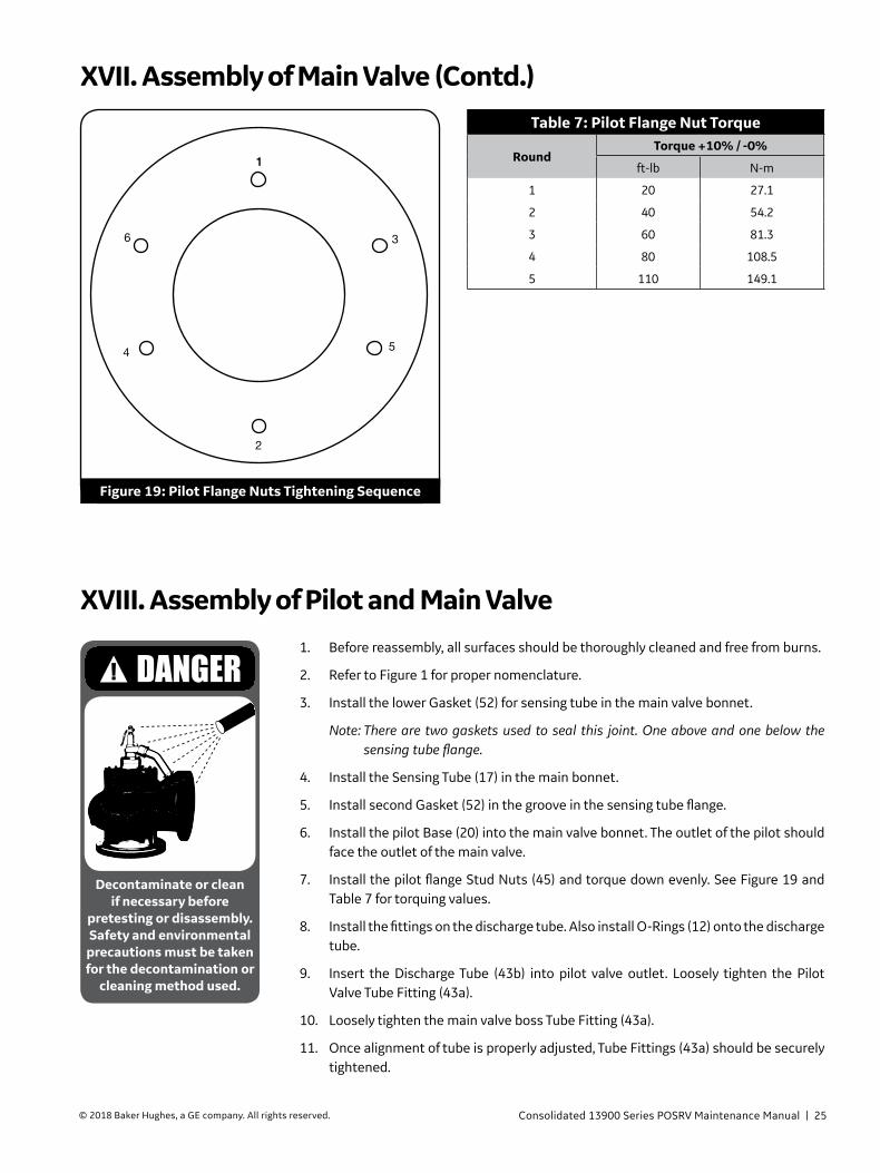
7. Install the pilot flange Stud Nuts (45) and torque down evenly. See Figure 19 and Table 7 for torquing values.
8. Install the fittings on the discharge tube. Also install O-Rings (12) onto the discharge tube.
9. Insert the Discharge Tube (43b) into pilot valve outlet. Loosely tighten the Pilot Valve Tube Fitting (43a).
10. Loosely tighten the main valve boss Tube Fitting (43a).
11. Once alignment of tube is properly adjusted, Tube Fittings (43a) should be securely tightened.
Decontaminate or clean if necessary before
pretesting or disassembly. Safety and environmental
precautions must be taken for the decontamination or
cleaning method used.
Table 7: Pilot Flange Nut Torque
RoundTorque +10% / -0%
ft-lb N-m
1 20 27.1
2 40 54.2
3 60 81.3
4 80 108.5
5 110 149.1
11
3
5
2
4
6
Figure 19: Pilot Flange Nuts Tightening Sequence
XVII. Assembly of Main Valve (Contd.)

26 | BHGE © 2018 Baker Hughes, a GE company. All rights reserved.
1. Due to large capacity of the main valve, it is impossible to adjust the pilot and main valve as an assembly unless on an actual installation. To obtain a valve setting on other than an actual installation, the pilot can be removed from the main valve and adjusted on a small test facility complying with the following requirements. Reference Figures 20 and 21.
a. The pressure source or the test header must have a minimum capacity of 6 ft3 (170 m3). Header mounting flange should be 4”-300# (101.6 mm - 20.4 barg) RF ASA flange.
b. The test fixture indicated in Figure 20 should be equipped with a 4”-300# (101.6 mm - 20.4 barg) RF ASA flange on the lower end and have appropriate machining and drilling on the top end to match the pilot flange (BHGE Part No. 4130901).
c. The test set up should be equipped with P1 and P2 pressure gauges as indicated in Figure 20. The P1 gauge will sense inlet pressure and P2 will sense pressure equivalent to that back of the main valve disc when the main valve is open.
2. The following procedure should be used for testing the pilot.
a. Install pilot valve with sensing unit. Lower flange and upper flange gasket on test fixture.
b. Pressurize system and note pop pressure indicated by P1 gauge. Adjust set pressure by loosening compression screw locknut and rotating compression screw clockwise (increase set point) or counterclockwise (decrease set point) until proper set pressure is established. Tighten compression screw locknut.
c. Adjust blowdown by removing adjusting ring pin and rotating adjusting ring clockwise (decrease blowdown) or counterclockwise (increase blowdown) until proper value is established. Blowdown is intentionally set for 10-12% of set pressure at factory before installing on the main valve. Tighten adjusting ring pin.
d. Pop pilot five times to ensure accurate settings noting P2 pressure at each pop. P2 pressure should drop to approximately 58% of P1.
e. Install lifting lever and cap on pilot. Bring system pressure up to just below the pilot set point and lift lever on pilot. Note that P2 does drop to approximately the same value indicated in Step d.
f. Check pilot for leakage. Bring the inlet pressure of the valve up to 94% of set pressure. Pass a cold rod across the outlet of the pilot. Any moisture occurring on the rod indicates valve leakage.
g. Test of main valve and pilot assembly:
(i) Install pilot back on main valve.
(ii) Upon pressurizing the system, leakage around main valve joints is permissible for approximately one hour till the valve is uniformly heated.
(iii) Increase system pressure until pilot opens at set point. Continue to overpressure until main valve opens.
(iv) Check valve for leakage with system pressure at 90% of set.
CAUTION Do not expose any part of the human body to the discharge side of either the pilot or main valve. When testing for leakage, stand 90° to the side of the outlet discharge. In this position it is safe to pass a metal rod downward across the outlet.
h. All external adjustments to the valve should be sealed in accordance with ASME Code Section VIII requirements.
XIX. Testing
Do not Stand or place hand in front of valve
discharge flange if valve is under pressure.

Consolidated 13900 Series POSRV Maintenance Manual | 27© 2018 Baker Hughes, a GE company. All rights reserved.
XIX. Testing (Contd.)
Pilot Valve
Test Fixture
HeaderP1 Pressure Gauge
Pressure Source
P2 Pressure Gauge
P1 Pressure Gauge
4"- 300"(101.60 - 7620.00 mm)ANSI Rating QuickOpening Valve(Fully Open During Test)
Drain Valve
P2 Pressure Gauge
Pilot Valve
Pilot Test FixtureBHGE ToolNumber 9500041
4" - 300"(101.60 - 7620.00 mm)
ANSI R. F. Flange
4" (101.60mm)MinimumInlet Pipe
From Air Or SteamPressure Source
MINIMUM CAPACITY6 CUBIC FEET
(23 LITERS)
Support Assembly
Figure 20: Pilot Testing Fixture
Figure 21: Pilot Test Fixture And Test Stand

28 | BHGE © 2018 Baker Hughes, a GE company. All rights reserved.
XIX. Testing (Contd.)
GAG BOLT
GAG SUPPORTCOLLAR
Figure 22: Gagging Arrangement
A. Hydrostatic Testing and Gagging Valves
In the event that it becomes necessary to gag the valves during a hydrostatic test, it will be required to first remove the lifting lever cap arrangement. Referring to Figure 2, remove cotter pin and lever pin (38) and lifting lever (33). Unscrew the cap lock screw (39) and remove the cap (37). Install the gag cap and gag as shown in Figure 22. Gag assemblies can be furnished by BHGE.
Care must be taken to prevent overgagging which will bend the spindle. In applying gags, remember that the valve spring will hold the valve closed against its set pressure. The additional gag load applied should be only enough to insure
that the valves do not lift at the expected overpressure.
Unit pressure should be brought within 80% of the pressure of the low set valve before applying the gags.
Tighten the gag with only a light force applied to the gag bolt.
Upon completion of the hydrostatic test, the valve should be allowed to set up approximately one hour so that liquid back of the main valve disc can drain out completely. Gag and gag cap should be removed and the lever cap, etc., installed in reverse sequence of the disassembly.

Consolidated 13900 Series POSRV Maintenance Manual | 29© 2018 Baker Hughes, a GE company. All rights reserved.
Table 8: Recommended Tooling and Equipment
No. Req.
Orificein2 114 143 176 200
cm2 735 923 1136 1290
Name of Part Part Number Part Number Part Number Part Number
1 Guide Lifting Fixture 4128201 4128201 4128201 4128201
1 O-Ring Retainer Fixture 9336901 9336901 9336901 9336901
1 Disc Installation Fixture 9337001 9337001 9336801 9336801
1 Pilot Valve Steam Test Fixture 4130901 4130901 4130901 4130901
1 Adjusting Ring Persuading Tool 4215501 4215501 4215501 4215501
2 Main Valve Guide Retainer Tool 4215301 4215301 4215301 4215301
1 Lubricant1 5153301 5153301 5153301 5153301
1 Truarc Pliers (Pilot Disc) 5153302 5153302 5153302 5153302
1 Truarc Pliers (O-Ring Seat Seal) 5153304 5153304 5153304 5153304
1 Truarc Pliers (Floating Washer) 5153305 5153305 5153305 5153305
1 Kwik-Ak-Shun Grinding Compound 199-11 199-11 199-11 199-11
1 2-1/8 Seat Lap 1672806 1672806 1672806 1672806
1 1” Thinwall Hex Socket 5153303 5153303 5153303 5153303
Note 1: Lubricant should be “Twist” by Century Corp. or equivalent.
XX. Maintenance Tools and Supplies

30 | BHGE © 2018 Baker Hughes, a GE company. All rights reserved.
A. General InformationThe importance of maintenance planning is the key to good plant operation. Part of that planning involves making sure that replacement parts needed to repair valves are available at the jobsite when required. Developing and implementing a standard valve maintenance plan will quickly pay for itself by eliminating costly downtime, unscheduled outages, etc.
B. Inventory PlanningThe basic objectives in formulating a replacement parts plan are:
• Prompt Availability• Minimum Downtime• Sensible Cost• Source Control
Having parts immediately available from plant storeroom inventory is obviously the best way to accomplish those objectives. Since it is impractical to have every part that might be needed to accomplish a given repair in stock at all times, guidelines for establishing meaningful inventory levels are summarized in the Table 9.
C. Replacement Parts List
Consult the Recommended Spare Parts list (see Section XXIII of this manual) to determine the parts to be included in the inventory plan.
Select the desired parts and determine those required for proper maintenance of the valve population in the plant.
D. Identification and Ordering Essentials
When ordering service parts, please furnish the following information to insure receiving the correct replacement parts:
1. Identify valve by the following nameplate data:
a. Size
b. Type
c. Temperature Class
d. Serial Number
Example:
16” 13906/114-2
SIN TC-56788
2. Specify parts required by:
a. Part Name
b. Part Number (if known)
c. Quantity
XXI. Replacement Parts Planning
Each time replacement parts are needed, keep these points in mind:
• BHGE designed the parts.• BHGE guarantees the parts.
• Consolidated valve products have been in service since 1879.
• BHGE has worldwide service.• BHGE has fast response availability for parts.
Table 9Part
ClassificationReplacement
FrequencyPredicted
Availability1
Class I Most Frequent 70%
Class II Less Frequent But Critical
85%
Class III Seldom Replaced 95%
Class IV Hardware 99%
Class V Practically Never Replaced
100%
Note 1: Predicted availability means that percentage of time the user plant will have the right parts to make the proper repair on the product, (i.e., if CLASS I parts are stocked at the owners facility, the parts needed to repair valve in question will be immediately available in 70% of all instances).
XXII. Genuine Consolidated Parts

Consolidated 13900 Series POSRV Maintenance Manual | 31© 2018 Baker Hughes, a GE company. All rights reserved.
Table 10: Recommended Spare Parts For Series 13900-3 Safety Relief Valve
Class Part Name
Quantity Parts / Same Size, Type, Set Pressure and
Temperature Class Valves in Service
Need Probability Coverage
I
Main Valve
70%
Seat Seal 1/1Guide Seal (1) 1/1Back-Up Ring (2) 2/1Bonnet Gasket (1) 1/1Sensing Tube Flange Gasket (2) 2/1Fitting Seal (2) 2/1Disc Retainer (1) 1/3Retainer Lock Ring (1) 1/3
Pilot ValveAlternate A (See Note 1)Complete Spare Pilot Valve 1/1Alternate B (See Note 2)Disc 1/1Disc Retainer Ring 1/1Adj. Ring Pin 1/1Bonnet Gasket 1/1Adj. Ring Pin Gasket 1/1Seal 1/1Sealing Wire 1/1
II
Main Valve
85%
Floating Washer 1/3Floating Washer Retainer 1/3Floating Washer Retainer Lock Ring 1/3
Pilot Valve (If Alternate B used for Class I)Guide 1/6Guide Pin 1/6Spindle Assembly 1/6Disc Holder 1/6Disc Collar 1/6
III
Main Valve
95%
Disc Spring 1/6Disc Spring Ring 1/6
Pilot Valve (If Alternate B used for Class I)Base 1/6Adj. Ring 1/6Spring 1/6Spring Washer (Bottom) 1/6Spring Washer (Top) 1/6Compression Screw 1/6
Note 1: Alternate A: If an auxiliary boiler is not available at the installation site for testing the pilot valve on steam at set pressure, it is recommended that spare pilot valves, which have been tested on steam be stocked in 1/1 ratio.
Note 2: Alternate B: If an adequate auxiliary boiler is available, stocking replacement parts for the pilot valves are recommended as the most economical approach.
XXIII. Recommended Spare Parts

32 | BHGE © 2018 Baker Hughes, a GE company. All rights reserved.
Table 10: Recommended Spare Parts For Series 13900-3 Safety Relief Valve (Contd.)
Class Part Name
Quantity Parts / Same Size, Type, Set Pressure and
Temperature Class Valves in Service
Need Probability Coverage
IV
Main Valve
99%
Disc Drain Plug 1/3Base Studs 1 Set/6114 in2 (16)143 in2 (20)176 in2 (20)200 in2 (20)Base Stud Nuts114 in2 (16)143 in2 (20)176 in2 (20)200 in2 (20)Eye Bolts (3) 1 Set/6Eye Bolt Lock Nuts (3) 1 Set/6Bonnet Stud Nuts (6) 1 Set/6Main Bonnet Plug 1/3
Pilot Valve (If Alternate B used for Class I)Cap 1/6Lever 1/6Lever Pin 1/6Cap Lock Screw 1/6Release Nut 1/6Release Lock Nut 1/6Compression Screw Lock Nut 1/6
V
Main Valve
Not Applicable
Base NoneDisc NoneGuide NoneBonnet NoneDischarge Tube Assembly NoneNameplate NoneNameplate Screws NoneDrain Plug None
Pilot Valve (If Alternate B used for Class I)Sensing Tube Assembly None Base Flange NoneBonnet NoneNameplate NoneNameplate Screws None
Note 1: Alternate A: If an auxiliary boiler is not available at the installation site for testing the pilot valve on steam at set pressure, it is recommended that spare pilot valves, which have been tested on steam be stocked in a 1/1 ratio.
Note 2: Alternate B: If an adequate auxiliary boiler is available, stocking replacement parts for the pilot valves are recommended as the most economical approach.
XXIII. Recommended Spare Parts (Contd.)

Consolidated 13900 Series POSRV Maintenance Manual | 33© 2018 Baker Hughes, a GE company. All rights reserved.
XXIV. Manufacturer’s Field Service, Repair and Training Programs
A. Field Service
BHGE maintains the largest and most competent field service staff in the industry. Service technicians are located at strategic points throughout the United States to respond to customers’ requirements for service. Each Service technician is factory trained and long experienced in servicing safety valves. BHGE’s Service technicians restore disc and seat bushing critical dimensions which affect valve performance, and are capable of modernizing valves in the field.
It is highly recommended that the professional talents of a BHGE Field Service technician be employed to make final field adjustments during the initial setting of all Consolidated Safety Valves.
B. Factory Repair FacilitiesBHGE’s Consolidated factory maintains a Repair Center. The Repair Department, in conjunction with the manufacturing facilities, is equipped to perform specialized repairs and product modifications, e.g., butt-welding, bushing replacements, code welding, and pilot replacement.
C. Maintenance TrainingThe rising costs of maintenance and repair in the utility and process industries indicate the need for trained maintenance personnel. BHGE conducts service seminars that help your maintenance and engineering personnel reduce these costs.
Seminars, conducted either at your site or ours, provide participants with an introduction to the basics of preventative maintenance necessary to minimize downtime, reduce unplanned repairs, and increase valve safety. While these seminars do not create “instant experts,” they do provide the participants with hands-on experience with Consolidated valves. The seminar also includes valve terminology and nomenclature, component inspection, troubleshooting, setting, and testing with emphasis on the ASME Boiler and Pressure Vessel Code.
For further information, please contact your local Green Tag Center.

GEA32551B 09/2018
*Denotes a trademark of Baker Hughes, a GE company, LLC.
Other company names and product names used in this document are the registered trademarks or trademarks of their respective owners.
© 2018 Baker Hughes, a GE company LLC - All rights reserved.
Baker Hughes, a GE company, LLC and its affiliates (“BHGE”) provides this information on an “as is” basis for general information purposes and believes it to be accurate as of the date of publication. BHGE does not make any representation as to the accuracy or completeness of the information and makes no warranties of any kind, specific, implied or oral, to the fullest extent permissible by law, including those of merchantability and fitness for a particular purpose or use. BHGE hereby disclaims any and all liability for any direct, indirect, consequential or special damages, claims for lost profits, or third party claims arising from the use of the information, whether a claim is asserted in contract, tort, or otherwise. The BHGE logo is a trademark of Baker Hughes, a GE company LLC. GE and the GE monogram are trademarks of the General Electric Company used under trademark license.
AUSTRALIABrisbane:Phone: +61-7-3001-4319Fax: +61-7-3001-4399
Perth:Phone: +61-8-6595-7018Fax: +61-8-6595-7299
Melbourne:Phone: +61-3-8807-6002Fax : +61-3-8807-6577
BELGIUMPhone: +32-2-344-0970Fax: +32-2-344-1123
BRAZILPhone: +55-19-2104-6900
CHINAPhone: +86-10-5738-8888Fax: +86-10-5918-9707
FRANCECourbevoiePhone: +33-1-4904-9000Fax: +33-1-4904-9010
GERMANYRatingenPhone: +49-2102-108-0Fax: +49-2102-108-111
INDIAMumbaiPhone: +91-22-8354790Fax: +91-22-8354791
New DelhiPhone: +91-11-2-6164175Fax: +91-11-5-1659635
ITALYPhone: +39-081-7892-111Fax: +39-081-7892-208
JAPANTokyo Phone: +81-03-6871-9008Fax: +81-03-6890-4620
KOREAPhone: +82-2-2274-0748Fax: +82-2-2274-0794
MALAYSIAPhone: +60-3-2161-0322Fax: +60-3-2163-6312
MEXICOPhone: +52-55-3640-5060
THE NETHERLANDSPhone: +31-15-3808666
RUSSIAVeliky NovgorodPhone: +7-8162-55-7898Fax: +7-8162-55-7921
MoscowPhone: +7 495-585-1276Fax: +7 495-585-1279
SAUDI ARABIAPhone: +966-3-341-0278Fax: +966-3-341-7624
SINGAPOREPhone: +65-6861-6100Fax: +65-6861-7172
SOUTH AFRICAPhone: +27-11-452-1550Fax: +27-11-452-6542
SOUTH & CENTRAL AMERICA AND THE CARIBBEANPhone: +55-12-2134-1201Fax: +55-12-2134-1238
SPAINPhone: +34-93-652-6430Fax: +34-93-652-6444
UNITED ARAB EMIRATESPhone: +971-4-8991-777Fax: +971-4-8991-778
UNITED KINGDOMBracknellPhone: +44-1344-460-500Fax: +44-1344-460-537
SkelmersdalePhone: +44-1695-526-00Fax: +44-1695-526-01
UNITED STATESJacksonville, FloridaPhone: +1-904-570-3409
Deer Park, TexasPhone: +1-281-884-1000Fax: +1-281-884-1010
Houston, TexasPhone: +1-281-671-1640Fax: +1-281-671-1735
DIRECT SALES OFFICE LOCATIONS
bhge.com