
Consistent Formulations of the Interaction Integral …jhkim/index_files/jam2005.pdfFracture of...
14
Jeong-Ho Kim 1 Glaucio H. Paulino 2 e-mail: [email protected] Department of Civil and Environmental Engineering, Newmark Laboratory, The University of Illinois at Urbana-Champaign, 205 North Mathews Avenue, Urbana, IL 61801 Consistent Formulations of the Interaction Integral Method for Fracture of Functionally Graded Materials The interaction integral method provides a unified framework for evaluating fracture parameters (e.g., stress intensity factors and T stress) in functionally graded materials. The method is based on a conservation integral involving auxiliary fields. In fracture of nonhomogeneous materials, the use of auxiliary fields developed for homogeneous ma- terials results in violation of one of the basic relations of mechanics, i.e., equilibrium, compatibility or constitutive, which naturally leads to three independent formulations: “nonequilibrium,” “incompatibility,” and “constant-constitutive-tensor.” Each formula- tion leads to a consistent form of the interaction integral in the sense that extra terms are added to compensate for the difference in response between homogeneous and nonhomo- geneous materials. The extra terms play a key role in ensuring path independence of the interaction integral. This paper presents a critical comparison of the three consistent formulations and addresses their advantages and drawbacks. Such comparison is made both from a theoretical point of view and also by means of numerical examples. The numerical implementation is based on finite elements which account for the spatial gra- dation of material properties at the element level (graded elements). fDOI: 10.1115/1.1876395g 1 Introduction Solid mechanics problems consist of the following three rela- tions: • equilibrium • compatibility • constitutive To determine fracture parameters, e.g., stress intensity factors sSIFsd and T stress, by means of the interaction integral sM integral 3 d method, auxiliary fields such as displacements su aux d, strains s« aux d, and stresses ss aux d are needed. In fracture of func- tionally graded materials sFGMsd, the use of the auxiliary fields developed for homogeneous materials results in violation of one of the three relations earlier, which leads to three independent formulations ssee Fig. 1d: nonequilibrium, incompatibility, and constant-constitutive-tensor formulations. Each formulation leads to a different final form of the resulting M integral, and for con- sistency, extra terms are added to compensate for the difference in response between homogeneous and nonhomogeneous materials. Table 1 illustrates the auxiliary fields corresponding to each for- mulation. Notice that the nonequilibrium formulation satisfies compatibility s« aux = ssym „ du aux d and the constitutive relations ss aux = Csxd« aux d, but violates equilibrium s„ · s aux 0 with no body forcesd. The incompatibility formulation satisfies equilib- rium and the constitutive relations, but violates compatibility con- ditions s« aux ssym „ du aux d. The constant-constitutive-tensor for- mulation satisfies equilibrium and compatibility conditions, but violates the constitutive relations ss aux = C tip « aux with C tip Csxdd. Conservation integrals based on these three consistent formula- tions are the focus of this paper. This paper is organized as follows. Section 2 comments on related work. Section 3 presents auxiliary fields for SIFs and T stress. Section 4 provides three consistent formulations using the interaction integral approach. Sections 5 and 6 establish the rela- tionships between M and SIFs and T stress, respectively. Section 7 provides comparison and critical assessment of the three consis- tent formulations. Sections 8 presents some numerical aspects rel- evant to the formulations. Section 9 presents two examples, which test different aspects of the formulations. Finally, Sec. 10 con- cludes this work. 2 Related Work The interaction integral method is an accurate and robust scheme for evaluating mixed-mode SIFs and T stress. The method is formulated on the basis of conservation laws, which lead to the establishment of a conservation integral for two admissible states of an elastic solid: actual and auxiliary. Yau et al. f5g presented the interaction integral method for evaluating SIFs in homoge- neous isotropic materials. Wang et al. f6g extended the method to homogeneous orthotropic materials, and Yau f7g used the method for bimaterial interface problems. Recently, the interaction integral method has been explored in the field of fracture of FGMs. It has been extended for evaluating SIFs f8–11g in isotropic FGMs. Dolbow and Gosz f8g employed the extended finite element method sX-FEMd; Rao and Rahman f9g used the element-free Galerkin method; and Kim and Paulino f10,11g used the finite element method sFEMd. In addition, the 1 Present address: Department of Civil and Environmental Engineering, The Uni- versity of Connecticut, 261 Glenbrook Road U-2037, Storrs, CT 06269. 2 To whom correspondence should be addressed. 3 Here, the so-called M integral should not be confused with the M integral of Knowles and Sternberg f1g, Budiansky and Rice f2g, and Chang and Chien f3g. Also, see the book by Kanninen and Popelar f4g for a review of conservation integrals in fracture mechanics. Contributed by the Applied Mechanics Division of THE AMERICAN SOCIETY OF MECHANICAL ENGINEERS for publication in the ASME JOURNAL OF AP- PLIED MECHANICS. Manuscript received by the Applied Mechanics Division, February 24, 2003; final revision, July 27, 2004. Associate Editor: K. Ravi-Chandar. Discussion on the paper should be addressed to the Editor, Professor Robert M. McMeeking, Journal of Applied Mechanics, Department of Mechanical and Environ- mental Engineering, University of California—Santa Barbara, Santa Barbara, CA 93106-5070, and will be accepted until four months after final publication in the paper itself in the ASME JOURNAL OF APPLIED MECHANICS. Journal of Applied Mechanics MAY 2005, Vol. 72 / 351 Copyright © 2005 by ASME
Transcript of Consistent Formulations of the Interaction Integral …jhkim/index_files/jam2005.pdfFracture of...
ctureterials.re ofus ma-
rium,ions:a-
s areonhomo-e of theistentis mades. Theal gra-
Jeong-Ho Kim1
Glaucio H. Paulino2
e-mail: [email protected]
Department of Civil and EnvironmentalEngineering,
Newmark Laboratory,The University of Illinois at Urbana-Champaign,
205 North Mathews Avenue,Urbana, IL 61801
Consistent Formulations of theInteraction Integral Method forFracture of Functionally GradedMaterialsThe interaction integral method provides a unified framework for evaluating fraparameters (e.g., stress intensity factors and T stress) in functionally graded maThe method is based on a conservation integral involving auxiliary fields. In fractunonhomogeneous materials, the use of auxiliary fields developed for homogeneoterials results in violation of one of the basic relations of mechanics, i.e., equilibcompatibility or constitutive, which naturally leads to three independent formulat“nonequilibrium,” “incompatibility,” and “constant-constitutive-tensor.” Each formultion leads to a consistent form of the interaction integral in the sense that extra termadded to compensate for the difference in response between homogeneous and ngeneous materials. The extra terms play a key role in ensuring path independencinteraction integral. This paper presents a critical comparison of the three consformulations and addresses their advantages and drawbacks. Such comparisonboth from a theoretical point of view and also by means of numerical examplenumerical implementation is based on finite elements which account for the spatidation of material properties at the element level (graded elements).fDOI: 10.1115/1.1876395g
ela
ct
c-sondedead
cetefo
fies
ns
ib-on-
or-but
mula-
s ondg therela-7
onsis-ts rel-hich
con-
bustd
o thetates
doge-tod
ed inting
nulino
U
in
TYP-ion,ndaertiron, Cth
1 IntroductionSolid mechanics problems consist of the following three r
tions:
• equilibrium• compatibility• constitutive
To determine fracture parameters, e.g., stress intensity fasSIFsd and T stress, by means of the interaction integralsMintegral3d method,auxiliary fields such as displacementssuauxd,strainss«auxd, and stressesssauxd are needed. In fracture of funtionally graded materialssFGMsd, the use of the auxiliary fielddeveloped for homogeneous materials results in violation ofof the three relations earlier, which leads to three indepenformulations ssee Fig. 1d: nonequilibrium, incompatibility, anconstant-constitutive-tensor formulations. Each formulation lto a different final form of the resultingM integral, and forcon-sistency, extra terms are added to compensate for the differenresponse between homogeneous and nonhomogeneous maTable 1 illustrates the auxiliary fields corresponding to eachmulation. Notice that the nonequilibrium formulation satis
1Present address: Department of Civil and Environmental Engineering, Theversity of Connecticut, 261 Glenbrook Road U-2037, Storrs, CT 06269.
2To whom correspondence should be addressed.3Here, the so-calledM integral should not be confused with theM integral of
Knowles and Sternbergf1g, Budiansky and Ricef2g, and Chang and Chienf3g. Also,see the book by Kanninen and Popelarf4g for a review of conservation integralsfracture mechanics.
Contributed by the Applied Mechanics Division of THE AMERICAN SOCIEOF MECHANICAL ENGINEERS for publication in the ASME JOURNAL OF APLIED MECHANICS. Manuscript received by the Applied Mechanics DivisFebruary 24, 2003; final revision, July 27, 2004. Associate Editor: K. Ravi-ChaDiscussion on the paper should be addressed to the Editor, Professor RobMcMeeking, Journal of Applied Mechanics, Department of Mechanical and Envmental Engineering, University of California—Santa Barbara, Santa Barbara93106-5070, and will be accepted until four months after final publication in
paper itself in the ASME JOURNAL OF APPLIED MECHANICS.Journal of Applied Mechanics Copyright © 200
-
ors
ent
s
inrials.r-
compatibility s«aux=ssym¹ duauxd and the constitutive relatiossaux=Csxd«auxd, but violates equilibriums¹ ·sauxÞ0 with nobody forcesd. The incompatibility formulation satisfies equilrium and the constitutive relations, but violates compatibility cditions s«auxÞ ssym¹ duauxd. The constant-constitutive-tensor fmulation satisfies equilibrium and compatibility conditions,violates the constitutive relationsssaux=Ctip«aux with CtipÞCsxdd.Conservation integrals based on these three consistent fortions are the focus of this paper.
This paper is organized as follows. Section 2 commentrelated work. Section 3 presents auxiliary fields for SIFs anTstress. Section 4 provides three consistent formulations usininteraction integral approach. Sections 5 and 6 establish thetionships betweenM and SIFs andT stress, respectively. Sectionprovides comparison and critical assessment of the three ctent formulations. Sections 8 presents some numerical aspecevant to the formulations. Section 9 presents two examples, wtest different aspects of the formulations. Finally, Sec. 10cludes this work.
2 Related WorkThe interaction integral method is an accurate and ro
scheme for evaluating mixed-mode SIFs andT stress. The methois formulated on the basis of conservation laws, which lead testablishment of a conservation integral for two admissible sof an elastic solid:actual and auxiliary. Yau et al.f5g presentethe interaction integral method for evaluating SIFs in homneous isotropic materials. Wang et al.f6g extended the methodhomogeneous orthotropic materials, and Yauf7g used the methofor bimaterial interface problems.
Recently, the interaction integral method has been explorthe field of fracture of FGMs. It has been extended for evaluaSIFs f8–11g in isotropic FGMs. Dolbow and Goszf8g employedthe extended finite element methodsX-FEMd; Rao and Rahmaf9g used the element-free Galerkin method; and Kim and Pa
ni-
r.M.-Ae
f10,11g used the finite element methodsFEMd. In addition, theMAY 2005, Vol. 72 / 3515 by ASME

thens-nd
o-
ses
heathee
auncnanicl a
Fskuefo
CC-oneteysse
odth
re oftused
knes.ip.an
s andnt
ng
rackwithDuek.
h as
uatetheho-
-l-lds
se-s thends
ssianliary
or
method has been employed to evaluateT stress in isotropicf11gand orthotropicf12g FGMs. In the aforementioned papers,interaction integral method has been investigated by meaeither an incompatibility formulation f8–12g or a constantconstitutive-tensor formulationf9g. Thus, for completeness aunification of concepts, this work introduces anonequilibrium for-mulation for evaluating SIFs andT stress in isotropic and orthtropic FGMs. These three basic formulationsssee Sec. 1d will beaddressed in this investigation, which includes a critical asment and comparison of the formulations.
The FEM has been widely used for fracture of FGMs. Eiscf13g evaluated mixed-mode SIFs by means of the pindependentJk
* integral. Gu et al.f14g evaluated SIFs using thstandardJ integral. Anlas et al.f15g calculated SIFs by using thpath-independentJ1
* integral. Marur and Tippurf16g investigatedcrack normal to the material gradient using the FEM in conjtion with experiments. Bao and Caif17g studied delaminatiocracking in a graded ceramic/metal substrate under mechand thermal loads. Bao and Wangf18g investigated periodicracking in graded ceramic/metal coatings under mechanicathermal loads. Kim and Paulinof19g evaluated mixed-mode SIby means of the path-independentJk
* integral, the modified cracclosure sMCCd, and the displacement correlation techniqMoreover, Kim and Paulino investigated mixed-mode SIFscracks arbitrarily oriented in orthotropic FGMs using the Mmethodf20g and the path-independentJk
* integralf21g. The nonsingular stresssT stressd of the Williams’s eigenfunction expansif22g has also been computed by means of the FEM. Beckerf23g studied T stress and finite crack kinking in FGMs. ThcalculatedT stress using the difference of the normal strealong u=0, i.e., ssxx−syyd. Recently, Kim and Paulinof11g pro-posed a unified approach using the interaction integral methevaluateT stress and SIFs in FGMs, and also investigatedeffect of T stress on crack initiation angles.
Fig. 1 Motivation for development of alternative consistentformulations. Notice that C„x…ÅCtip for xÅ0. The area A de-notes a representative region around the crack tip.
Table 1 Comparison of alternative formulations
Nonequilibriumformulation
Incompatibilityformulation
Constant-constitutive-tensformulation
uaux uaux uaux
«aux saux «aux
saux=Csxd«aux «aux=Ssxdsaux saux=Ctip«aux
= ·sauxÞ0 «auxÞ ssym=duaux CsxdÞCtip
352 / Vol. 72, MAY 2005
of
s-
n-
-
cal
nd
.r
al.
s
toe
Other methods have also been used to investigate fractuFGMs ssee the papers by Erdoganf24g, Nodaf25g, and Paulino eal. f26gd. Analytical or semi-analytical approaches have beenby Delale and Erdoganf27g, Erdoganf24g, Erdogan and Wuf28g,and Chan et al.f29g. Delale and Erdoganf30g investigated a cracin a FGM layer between two dissimilar homogeneous half-plaGu and Asarof31g studied a semi-infinite crack in a FGM strShbeeb et al.f32,33g studied multiple cracks interacting ininfinite nonhomogeneous plate. Honein and Herrmannf34g stud-ied conservation laws in nonhomogeneous plane elastostaticinvestigated a semi-infinite crack by using the path-independeJeintegral. Gu and Asarof31g studied orthotropic FGMs consideria four-point bending specimen. Ozturk and Erdoganf35,36g usedintegral equations to investigate mode I and mixed-mode cproblems in an infinite nonhomogeneous orthotropic mediuma crack aligned with one of the principal material directions.to its generality, the FEM is the method of choice in this wor
3 Auxiliary FieldsThe interaction integral makes use of auxiliary fields, suc
displacementssuauxd, strains s«auxd, and stressesssauxd. Theseauxiliary fields have to be suitably defined in order to evalmixed-mode SIFs andT stress. There are various choices forauxiliary fields. Here we adopt fields originally developed formogeneous materials. For each formulations nonequilibrium, incompatibility, constant-constitutive tensord, the selection of auxiiary fields is done according to Table 1. The auxiliary fieadopted in this paper are described later.
3.1 Fields for SIFs.For evaluating mixed-mode SIFs, welect the auxiliary displacement, strain, and stress fields acrack-tip asymptotic fieldssi.e., Osr1/2d for the displacements aOsr−1/2d for the strains and stressesd with the material propertiesampled at the crack-tip locationse.g., Ref.f13gd: Figure 2 showa crack in a FGM under two-dimensional fields in local Carteand polar coordinates originating at the crack tip. The auxidisplacement, strain, and stress fields are chosen asf22,37g:
uaux= KIauxf Isr1/2,u,atipd + KII
auxf IIsr1/2,u,atipd s1d
aux aux
Fig. 2 Cartesian „x1,x2… and polar „r ,u… coordinates originat-ing from the crack tip in a nonhomogeneous material subjectedto traction „t… and displacement boundary conditions
« = ssym¹ du , s2d
Transactions of the ASME
s,pli-
in
in
hee titeTh
en
etiv-
ter
of
ar
-
y
d in
-
saux= KIauxgIsr−1/2,u,atipd + KII
auxgIIsr−1/2,u,atipd s3d
whereKIaux andKII
aux are the auxiliary mode I and mode II SIFrespectively, andatip denotes contracted notation of the comance tensorS evaluated at the crack tip, which is explainedAppendix A. The representative functionsfsr1/2,u ,atipd andgsr−1/2,u ,atipd are given in Appendix B and can also be foundother references, e.g., Refs.f37,38g.
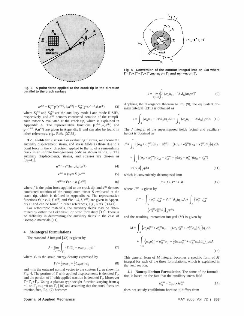
3.2 Fields forT stress.For evaluatingT stress, we choose tauxiliary displacement, strain, and stress fields as those dupoint force in thex1 direction, applied to the tip of a semi-infincrack in an infinite homogeneous body as shown in Fig. 3.auxiliary displacements, strains, and stresses are chosf39–41g:
uaux= tusln r,u, f,atipd s4d
«aux= ssym¹ duaux s5d
saux= tssr−1,u, f,atipd s6d
wheref is the point force applied to the crack tip, andatip denotescontracted notation of the compliance tensorS evaluated at thcrack tip, which is defined in Appendix A. The representafunctionstusln r ,u , f ,atipd andtssr−1,u , f ,atipd are given in Appendix C and can be found in other references, e.g., Refs.f39,41g.
For orthotropic materials, the auxiliary fields may be demined by either the Lekhnitskii or Stroh formalismf12g. There isno difficulty in determining the auxiliary fields in the caseisotropic materialsf11g.
4 M-integral formulationsThe standardJ integral f42g is given by
J = limGs→0
EGs
sWd1j − si jui,1dnjdG s7d
whereW is the strain energy density expressed by
W = 12si j«i j = 1
2Cijkl«kl«i j s8d
andnj is the outward normal vector to the contourGs, as shown inFig. 4. The portion ofG with applied displacements is denotedGu,and the portion ofG with applied traction is denotedGt. MoreoverG=Gu+Gt. Using a plateau-type weight function varying fromq=1 onGs to q=0 onG0 f10g and assuming that the crack faces
Fig. 3 A point force applied at the crack tip in the directionparallel to the crack surface
traction-free, Eq.s7d becomes
Journal of Applied Mechanics
o a
eas
e
-
e
J = limGs→0
RG
ssi jui,1 − Wd1jdmjqdG s9d
Applying the divergence theorem to Eq.s9d, the equivalent domain integralsEDId is obtained as
J =EA
ssi jui,1 − Wd1jdq,jdA+EA
ssi jui,1 − Wd1jd,jqdA s10d
The J integral of the superimposed fieldssactual and auxiliarfieldsd is obtained as
Js =EA
hssi j + si jauxdsui,1 + ui,1
auxd − 12ssik + sik
auxds«ik + «ikauxdd1jjq,jdA
+EA
hssi j + si jauxdsui,1 + ui,1
auxd − 12ssik + sik
auxds«ik + «ikauxd
3sd1jdj,jqdA s11d
which is conveniently decomposed into
Js = J + Jaux+ M s12d
whereJaux is given by
Jaux=EA
ssi jauxui,1
aux− Wauxd1jdq,jdA+EA
hsi jauxui,1
aux
− 12sik
aux«ikauxd1jj,jqdA
and the resulting interaction integralsMd is given by
M =EA
hsi jui,1aux+ si j
auxui,1 − 12ssik«ik
aux+ sikaux«ikdd1jjq,jdA
+EA
hsi jui,1aux+ si j
auxui,1 − 12ssik«ik
aux+ sikaux«ikdd1jj,jqdA
s13d
This general form ofM integral becomes a specific form ofMintegral for each of the three formulations, which is explainethe next section.
4.1 Nonequilibrium Formulation. The name of the formulation is based on the fact that the auxiliary stress field
si jaux= Cijklsxd«kl
aux s14d
Fig. 4 Conversion of the contour integral into an EDI whereG=G0+G+−Gs +G−,mj =nj on G0 and mj =−nj on Gs
does not satisfy equilibrium because it differs from
MAY 2005, Vol. 72 / 353

nd
u-fo
en-theg
d
apTh
-
i-
ap-he
-
Eq.
ual
alatch,iew.
, theas
tion.
-
si jaux= sCijkldtip«kl
aux, s15d
where Cijklsxd is the constitutive tensor of the actual FGM asCijkldtip is the constitutive tensor at the crack tipssee Fig. 1d. Thederivatives of the auxiliary stress field are
si j ,jaux= Cijkl ,jsxd«kl
aux+ Cijklsxd«kl,jaux= sCijkldtip«kl,j
aux+ Cijkl ,jsxd«klaux
+ fCijklsxd − sCijkldtipg«kl,jaux, s16d
where the underlined term in Eq.s16d vanishes. Thus this argment confirms that the auxiliary stress field selected in thismulationsEq. s14dd does not satisfy equilibrium, i.e.,si j ,j
auxÞ0 snobody forces or inertiad. This choice of the auxiliary fields has bediscussed by Dolbow and Goszf8g, but a nonequilibrium formulation was not provided in their paper. The nonequilibrium instress field has to be taken into account in the interaction intformulation, which is discussed in detail later.
Using the following equality:
si j«i jaux= Cijklsxd«kl«i j
aux= sklaux«kl = si j
aux«i j s17done rewrites Eq.s13d as
M =EA
hsi jui,1aux+ si j
auxui,1 − sik«ikauxd1jjq,jdA+E
A
hsi jui,1aux
+ si jauxui,1 − sik«ik
auxd1jj,jqdA= M1 + M2 s18d
The last term of the second integralsM2d in Eq. s18d is expresseas
ssik«ikauxd1jd,j = ssik«ik
auxd,1 = ssi j«i jauxd,1 = sCijkl«kl«i j
auxd,1
= Cijkl ,1«kl«i jaux+ Cijkl«kl,1«i j
aux+ Cijkl«kl«i j ,1aux
= Cijkl ,1«kl«i jaux+ si j
aux«i j ,1 + si j«i j ,1aux s19d
Substitution of Eq.s19d into Eq. s18d leads to
M2 =EA
ssi j ,jui,1aux+ si jui,1j
aux+ si j ,jauxui,1 + si j
auxui,1jdqdA
−EA
sCijkl ,1«kl«i jaux+ si j
aux«i j ,1 + si j«i j ,1auxdqdA s20d
Using compatibility sactual and auxiliaryd and equilibriumsac-tuald si.e., si j ,j =0 with no body forced, one simplifies Eq.s20d as
M2 =EA
hsi j ,jauxui,1 − Cijkl ,1«kl«i j
auxjqdA s21d
Therefore the resulting interaction integralsMd becomes
M =EA
hsi jui,1aux+ si j
auxui,1 − sik«ikauxd1jjq,jdA+E
A
hsi j ,jauxui,1
− Cijkl ,1«kl«i jauxjqdA s22d
where the underlined term is a nonequilibrium term, whichpears due to nonequilibrium of the auxiliary stress fields.existence of the final form ofM integral for FGMs in Eq.s22d hasbeen proved by Kimf43g and Paulino and Kimf44g.
4.2 Incompatibilty Formulation. The incompatibility formulation satisfies equilibriumssi j ,j
aux=0 with no body forcesd and theconstitutive relationships«i j
aux=Sijklsxdsklauxd, but violates compat
blity conditionss«i jauxÞ sui,j
aux+uj ,iauxd /2d. Thus Eq.s20d is also valid
for this formulation. Using equilibriumsactual and auxiliaryd andcompatibility sactuald, one simplifiesM2 as
M2 =EA
hsi jsui,1jaux− «i j ,1
auxd − Cijkl ,1«kl«i jauxjqdA
Therefore the resulting interaction integralsMd becomes
354 / Vol. 72, MAY 2005
r-
eral
-e
M =EA
hsi jui,1aux+ si j
auxui,1 − sik«ikauxd1jjq,jdA+E
A
hsi jsui,1jaux− «i j ,1
auxd
− Cijkl ,1«kl«i jauxjqdA s23d
where the underlined term is an incompatibility term, whichpears due to incompatibility of the auxiliary strain fields. Texistence of the final form ofM integral for FGMs in Eq.s23d hasbeen proved by Kimf43g.
4.3 Constant-Constitutive-Tensor Formulation. The constant-constitutive-tensor formulation satisfies equilibriumssi j ,j
aux
=0 with no body forcesd and compatiblity conditionss«i jaux
=sui,jaux+uj ,i
auxd /2d, but violates the constitutive relationshipssi jaux
=sCijkldtip«klaux with sCijkldtipÞCijklsxdd. Notice that si j«i j
aux
Þsi jaux«i j due to the violated constitutive relationship. Thus
s13d becomes
M =EA
hsi jui,1aux+ si j
auxui,1 − 12ssik«ik
aux+ sikaux«ikdd1jjq,jdA
+EA
hsi j ,jui,1aux+ si jui,1j
aux+ si j ,jauxui,1 + si j
auxui,1j − 12ssi j ,1«i j
aux
+ si j«i j ,1aux+ si j ,1
aux«i j + si jaux«i j ,1djqdA s24d
Using equilibrium and compatibility conditions for both actand auxiliary fields, one obtainsM as
M =EA
hsi jui,1aux+ si j
auxui,1 − 12ssik«ik
aux+ sikaux«ikdd1jjq,jdA
+EA
12hsi j«i j ,1
aux− si j ,1«i jaux+ si j
aux«i j ,1 − si j ,1aux«i jjqdA s25d
Notice that the resultingM involves derivatives of the actustrain and stress fields, which arises due to the material mismand may cause loss of accuracy from a numerical point of vThe existence of the final form ofM integral for FGMs in Eq.s25dhas been proved by Kimf43g.
5 Extraction of Stress Intensity FactorsFor mixed-mode crack problems on orthotropic materials
energy release ratesGI andGII are related to mixed-mode SIFsfollows f37g:
GI = −KI
2a22
tip ImFKIsm1tip + m2
tipd + KII
m1tipm2
tip G s26d
GII =KII
2a11
tip ImfKIIsm1tip + m2
tipd + KIsm1tipm2
tipdg s27d
where Im denotes the imaginary part of the complex funcThus
Jlocal = G = GI + GII = c11KI2 + c12KIKII + c22KII
2 s28d
where
c11 = −a22
tip
2ImSm1
tip + m2tip
m1tipm2
tip Dc12 = −
a22tip
2ImS 1
m1tipm2
tipD +a11
tip
2Imsm1
tipm2tipd
c22 =a11
tip
2Imsm1
tip + m2tipd s29d
For two admissible fields, which are the actualsu ,« ,sd and auxaux aux aux
iliary su ,« ,s d fields, one obtainsf6g:Transactions of the ASME

fo
at, t
rthforloc
foch
ul-ed
ire
for
ce interials.
theeint of
lationpar-
r-usecor-
ed intant-
hewith
ased
ions,on’s
e
Jlocals = c11sKI + KI
auxd2 + c12sKI + KIauxdsKII + KII
auxd + c22sKII
+ KIIauxd2 = Jlocal + Jlocal
aux + M local s30d
whereJlocal is given by Eq.s28d, Jlocalaux is given by
Jlocalaux = c11sKI
auxd2 + c12KIauxKII
aux+ c22sKIIauxd2 s31d
andM local is given by
M local = 2c11KIKIaux+ c12sKIKII
aux+ KIauxKIId + 2c22KIIKII
aux
s32d
The mode I and mode II SIFs are evaluated by solving thelowing linear algebraic equations:
M locals1d = 2c11KI + c12KII, sKI
aux= 1.0,KIIaux= 0.0d s33d
M locals2d = c12KI + 2c22KII, sKI
aux= 0.0,KIIaux= 1.0d s34d
where the superscript inM localsid si =1,2d is used just to indicate th
the values are distinct in each case. For isotropic materialsoff-diagonal terms ofcij drop, and Eqs.s33d and s34d become
M locals1d =
2
Etip* KI sKI
aux= 1.0,KIIaux= 0.0d s35d
M locals2d =
2
Etip* KII, sKI
aux= 0.0,KIIaux= 1.0d s36d
respectively, whereEtip* =Etip for plane stress andEtip
* =Etip / s1−ntip
2 d for plane strain. The relationships of Eqs.s33d ands34d, andEqs.s35d ands36d are the same as those for homogeneous otropic f6g and isotropicf5g materials, respectively, except that,FGMs, the material properties are evaluated at the crack-tiption. Notice that, for the orthotropic case, there is no needNewton’s iteration, which is needed with other approaches suthe path-independentJk integral f21g and the MCC integralf20g.Here the SIFs for mode I and mode II are naturally decoupledscf.Eqs.s33d and s34dd.
6 Extraction of T StressT stress can be extracted from the interaction integral by n
fying the contributions of both singularsi.e., Osr−1/2dd and higherorder si.e., Osr1/2d and higherd terms. The derivation is explainin detail by Kim and Paulinof11,12g and Paulino and Kimf44g.From the earlier derivation of Eq.s13d, theM integral in the formof line integral is obtained as
M local = limGs→0
EGs
hsik«ikauxd1j − si jui,1
aux− si jauxui,1jnjdG s37d
Here we can consider only the stress parallel to the crack dtion, i.e.:
si j = Td1id1j s38d
Substituting Eq.s38d into Eq. s37d, one obtains
M local = − limGs→0
EGs
si jauxnjui,1dG = Ta11
tip limGs→0
EGs
si jauxnjdG
s39d
Because the forcef is in equilibrium ssee Fig. 3d:
f = − limGs→0
EGs
si jauxnjdG s40d
and thus the following relationship is obtained:
Journal of Applied Mechanics
l-
he
o-
a-ras
li-
c-
T =M local
fa11tip s41d
where a11tip is a material parameter at the crack tip location
plane stress, and is replaced byb11tip for plane strainscf. Eq. s65dd.
For isotropic materials, Eq.s41d becomes
T =Etip
*
fM local s42d
whereEtip* =Etip for plane stress andEtip
* =Etip / s1−ntip2 d for plane
strain.
7 Comparison and Critical AssessmentThe three formulations presented earlier areconsistentin the
sense that extra terms are added to account for the differenresponse between homogeneous and nonhomogeneous maHowever, each formulation has an independent final formsseeEqs.s22d, s23d, ands25dd due to the different characteristics ofauxiliary fields. The final form of theM integral for each of thesformulations is compared and assessed from a theoretical poview later.
The nonequilibrium formulation results in the simplest finaMintegral thus requiring the least computation and implementeffort among the three formulations. This is observed by coming Eqs.s22d, s23d, and s25d. Moreover, the nonequilibrium fomulation is equivalent to the incompatibility formulation, becaboth formulations involve the same constitutive relations andresponding material derivatives. This equivalence is observthe numerical examples of Sec. 9. However, the consconstitutive-tensor formulationf9g requires the derivatives of tactual stress field, which may introduce accuracy problemsstandardC0 elements commonly used in the displacement-bFEM.
In order to further compare the three consistent formulatlet’s consider an exponentially graded material in which Poissratio is constant and Young’s modulus varies in any directionsseeFig. 5d:
Esx1d = E0 expsdx1d = E0 expsb1X1 + b2X2d s43d
n = constant s44d
whereX=sX1,X2d refers to a global coordinate system,x1 is thedirection of material gradationsinclined byum with respect to thX1 coordinated, and the nonhomogeneity parametersd, b1, andb2
Fig. 5 Crack geometry in a nonhomogeneous material, whichis graded along the x1 direction
are related by
MAY 2005, Vol. 72 / 355

thpa
tialch
-dth
-
ro-he
thfgeib-
-
t
use
-tem,
mayterial
s ofuse
s be-func-
ality,tives
mu-
con-s
nces,
b1 = d cosum, b2 = d sinum s45d
This selection of material property leads to simplification ofresultingM integrals and allows one to better assess and comthe characteristics of the formulations. Moreover, exponengraded materials have been extensively investigated in the tecal literature, e.g., Refs.f8,15,19,21,24,27–36,45–48g. The resulting M integrals corresponding to the three formulations arerived later in the global coordinate system, which is used innumerical implementationssee Sec. 8 laterd.
7.1 Nonequilibrium Formulation. The derivatives of interest, with respect to the global coordinate system, aresm=1,2d
si j ,jaux= Cijkl ,jsXd«kl
aux+ CijklsXd«kl,jaux= b jCijklsXd«kl
aux+ CijklsXd«kl,jaux
= b jCijklsXd«klaux+ apsCijkldtip«kl,j
aux= b jsi jaux s46d
Cijkl ,m = bmCijklsXd s47d
whereap=expsb1X1+b2X2d is a factor that arises due to the pportionality of Cijkl for the material gradation considered. Tglobal interaction integralsMmdglobal sm=1,2d is given by
sMmdglobal=EA
hsi jui,maux+ si j
auxui,m − sik«ikauxd1jj
]q
]XjdA
+EA
hsi j ,jauxui,m − Cijkl ,m«kl«i j
auxjqdA s48d
Substitution of Eqs.s46d and s47d into Eq. s48d yields sm=1,2d:
sMmdglobal=EA
hsi jui,maux+ si j
auxui,m − sik«ikauxdmjj
]q
]XjdA
+EA
hb jsi jauxui,m − bmsi j«i j
auxjqdA s49d
Notice that, for this particular case, a simpler expression thanfor the general case is obtainedscf. Eq. s22dd. The derivatives omaterial properties are represented by the material nonhomoity b in Eq. s49d. Moreover, the contribution of the nonequilrium term to theM integral is related to the value ofb.
7.2 Incompatibility Formulation. The derivatives of interest, with respect to the global coordinate system, aresm=1,2d:
«i j ,maux = Sijkl ,msXdskl
aux+ SijklsXdskl,maux = − bmSijklsXdskl
aux
+ SijklsXdskl,maux = − bm«i j
aux+ SijklsXdskl,maux s50d
together with Eq.s47d. The global interaction integralsMmdglobalsm=1,2d is given by
sMmdglobal=EA
hsi jui,maux+ si j
auxui,m − sik«ikauxdmjj
]q
]XjdA
+EA
hsi jsui,mjaux − «i j ,m
auxd − Cijkl ,m«kl«i jauxjqdA s51d
Substitution of Eqs.s50d and s47d into Eq. s51d yields sm=1,2d:
sMmdglobal=EA
hsi jui,maux+ si j
auxui,m − sik«ikauxdmjj
]q
]XjdA
+EA
hsi jui,mjaux − si j ,m
aux«i jjqdA s52d
Notice that, for this particular case, the finalM integral does noinvolve any derivatives of material propertiesscf. Eq. s23dd. In
this formulation, the first integral of Eq.s52d is the same as that356 / Vol. 72, MAY 2005
ere
lyni-
e-e
at
ne-
for the nonequilibrium formulation, because both formulationsthe same constitutive tensorCsXd.
7.3 Constant-Constitutive-Tensor Formulation. The derivatives of interest, with respect to the global coordinate sysare sm=1,2d:
si j ,m = Cijkl ,msXd«kl + CijklsXd«kl,m = bmCijklsXd«kl + CijklsXd«kl,m
= bmsi j + CijklsXd«kl,m s53d
si j ,maux = sCijkldtip«kl,m
aux s54d
The global interaction integralsMmdglobal sm=1,2d is given by
M =EA
Hsi jui,maux+ si j
auxui,m −1
2ssik«ik
aux+ sikaux«ikddmjJ ]q
]XjdA
+EA
1
2hsi j«i j ,m
aux − si j ,m«i jaux+ si j
aux«i j ,m − si j ,maux«i jjqdA s55d
Substitution of Eqs.s53d and s54d into Eq. s55d yields sm=1,2d:
M =EA
Hsi jui,maux+ si j
auxui,m −1
2ssik«ik
aux+ sikaux«ikddmjJ ]q
]XjdA
+EA
1
2hsi j«i j ,m
aux − bmsi j«i jaux− Cijkl«kl,m«i j
aux+ si jaux«i j ,m
− sCijkldtip«kl,maux «i jjqdA s56d
whereCijkl ;CijklsXd. Notice that, for this case, the finalM inte-gral requires the derivatives of the actual strain field, whichhave numerical accuracy problems. The derivatives of maproperties are represented by the material nonhomogeneityb inEq. s56d. Moreover, the first integral of Eq.s56d is different fromthose for the other two formulations.
8 Some Numerical AspectsFor numerical computation by means of the FEM, theM inte-
gral is evaluated first in global coordinatesssMmdglobald and thentransformed to local coordinatessM locald. The M integralssMmdglobal for the three consistent formulations have derivativematerial properties in common. In this paper, we do notclosed-form expressions for derivatives of material propertiecause these expressions would be specific to each specifiction or micromechanics model. Thus, for the sake of generwe determine such derivatives by using shape function derivaof finite elementsf19,45g.
The derivatives involving material derivatives for each forlation are
•nonequilibrium:si j ,jaux= Cijkl ,j«kl
aux+ Cijkl«kl,jaux s57d
•incompatibility: «i j ,maux = Sijkl ,mskl
aux+ Sijklskl,maux s58d
•constant-constitutive-tensor:si j ,m = Cijkl ,m«kl + Cijkl«kl,m
s59d
A simple and general approach to evaluate such derivativessists of using shape function derivativesf11g. Thus the derivativeof a generic quantityP se.g.,Cijkl , Sijkl , or «i j d are obtained as
]P
]Xm= o
i=1
n]Ni
]XmPi, sm= 1,2d s60d
wheren is the number of element nodes andNi =Nisj ,hd are theelement shape functions which can be found in many refere
e.g., Ref.f49g. The derivatives]Ni /]Xm are obtained asTransactions of the ASME

tin
IFb
e ftanex
de
f theon thedhese
hichs ma-
ele-rter-t-k-
ck
thed byr torst
H]Ni/]X1
]Ni/]X2J = J−1H ]Ni/]j
]Ni/]hJ s61d
whereJ−1 is the inverse of the standard Jacobian matrix relasX1,X2d with sj ,hd f49g.
9 Numerical ExamplesThe performance of the interaction integral for evaluating S
and T stress in isotropic and orthotropic FGMs is examinedmeans of numerical examples. This paper employs the thremulations, such as nonequilibrium, incompatibility, and consconstitutive tensor, for numerical investigation. The followingamples are presented
s1d Inclined center crack in a plates2d Strip with an edge crack
All the examples are analyzed using the FEM codeI-FRANC2D4.
sIllinois; FRacture ANalysis Code2Dd, which is based on the co
4
Fig. 6 Example 1: FGM plate with an inclinedand boundary conditions „BCs … under fixed-grcontours for EDI computation of M integral; „
rings „R4… around the crack tips „u=18° coun
The FEM codeI-FRANC2D was formerly calledFGM-FRANC2D f19g.
Journal of Applied Mechanics
g
syor-t--
FRANC2D f50,51g developed at Cornell University. TheI-FRANC2D
element library for FGMs consists ofgraded elementsf19,46,45g,which incorporate the material gradient at the size scale oelement. The specific graded elements used here are basedgeneralized isoparametric formulationpresented by Kim anPaulinof19g, who have also compared the performance of telements with that of conventional homogeneous elements wproduce a step-wise constant approximation to a continuouterial property fieldf45g.
All the geometry is discretized with isoparametric gradedmentsf19g. The specific elements used consist of singular quapoint six-node trianglessT6qpd for crack-tip discretization, eighnode serendipity elementssQ8d for a circular region around cractip elements, and regular six-node trianglessT6d in a transitionzone toQ8 elementsssee, for example, Fig. 6, for a typical cratip region discretizationd.
All the examples consist of SIFs andT stress results for boisotropic and orthotropic FGMs, and those results are obtainthe interaction integral in conjunction with the FEM. In ordevalidate SIFs andT stress solutions, the FEM results for the fi
ck with geometric angle u: „a… geometryoading; „b… typical finite element mesh; „c…mesh detail using 12 sectors „S12… and four-clockwise …
craip ld…ter
examplesan inclined center crack in an exponentially graded plate
MAY 2005, Vol. 72 / 357

i-olvestct
le¯ g;
.
une,es,-gr-
rs:
SIFsnsoro-ltsckeenin
notriumEr-
%heriumhalfained.tourfor
e forntoure, andssion,ricaltresser the
r-
hn iner-
subjected to fixed-grip loadingd are compared with available semanalytical and numerical solutions. The second example invhyperbolic-tangent functions for material properties and invgates the effect of translation of these properties with respethe crack-tip location.
9.1 Inclined Center Crack in a Plate.Figure 6sad shows aninclined center crack of length 2a located with a geometric ang
u scounter-clockwised in a plate subjected to fixed-grip loadinFig. 6sbd shows the complete mesh configuration; Fig. 6scd showsfive contours used for EDI computation of theM integral; and Fig6sdd shows the mesh detail using 12 sectorssS12d and four ringssR4d of elements around the crack tips. The displacement boary condition is prescribed such thatu2=0 along the lower edgand u1=0 for the node at the lower left-hand side. The mdiscretization consists of 1641Q8, 94 T6, and 24T6qpelementswith a total of 1759 elements and 5336 nodes. The fixedloading results in a uniform strain«22sX1,X2d= « in a corresponding uncracked structure, which corresponds tos22sX1,10d= «E0ebX1 for isotropic FGMs ands22sX1,10d= «E22
0 ebX1 fororthotropic FGMs ssee Fig. 6sadd. Young’s moduli and sheamodulus are exponential functions ofX1, while Poisson’s ratio iconstant. The following data were used in the FEM analyses
plane stress, 23 2 Gauss quadrature
dimensionless nonhomogeneity parameter:ba = 0.5
a/W= 0.1, L/W= 1.0, u = 0 ° to 90 ° , « = 1
Isotropic case
EsX1d = E0ebX1, nsX1d = n
E0 = 1.0, n = 0.3
Table 2 Example 1: comparison of normalized=0.5 „K0= «E0Îpa… „see Fig. 6 …. Contour 5 sconstitutive-tensor formulation. The results for thelations are almost identical and thus the resultshere.
Method u KI+/K0
Konda andErdoganf47g
0° 1.42418° 1.28536° 0.92554° 0.49072° 0.14690° 0.000
Nonequilibrium 0° 1.42318° 1.28336° 0.92254° 0.48872° 0.14590° 0.000
Constant-constitutive tensor
0° 1.42618° 1.28036° 0.92254° 0.48672° 0.14390° 0.000
Dolbowand Goszf8g
sX-FEMd
0° 1.44518° 1.30336° 0.93054° 0.48872° 0.14290° 0.000
Orthotropic case
358 / Vol. 72, MAY 2005
esi-to
d-
h
ip
E11sX1d = E110 ebX1, E22sX1d = E22
0 ebX1,
G12sX1d = G120 ebX1, n12sX1d = n12
0
E110 = 104, E22
0 = 103, G120 = 1216, n12
0 = 0.3
Table 2 compares the present FEM results for normalizedobtained by the nonequilibrium and constant-constitutive-teformulations of theM integral with semi-analytical solutions prvided by Konda and Erdoganf47g and the extended FEM resuby Dolbow and Goszf8g for various geometric angles of a crain isotropic FGMs. The difference in the result for SIFs betwnonequilibrium and incompatibility formulations is found to bethe orderOs10−4d in this example, and thus the results areprovided. The converged results obtained by the nonequilibformulation are in good agreement with those by Konda anddoganf47g smaximum difference 1.3%, average difference 0.6d,those by Dolbow and Goszf8g, and those obtained by tconstant-constitutive-tensor formulation. For the nonequiliband incompatibility formulations, a domain including almostof the square plate is used, and converged solutions are obtHowever, for the constant-constitutive-tensor formulation, con5 as shown in Fig. 6scd is used. We observe that the accuracythe constant-constitutive-tensor formulation are reasonablsmall size of contours such as contours 1–5, but as the cobecomes large than contour 5, the solution does not convergaccuracy deteriorates. As explained in the theoretical discuthe constant-constitutive-tensor formulation may have numeproblems in the accuracy of derivatives of actual strain or sfields. To reduce domain dependence, mesh discretization ovplate shown in Fig. 6sbd needs to be improved.
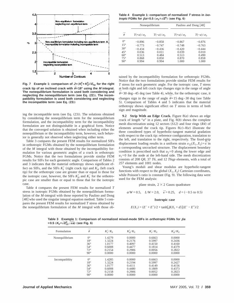
Figure 7 showsJ=sKI2+KII
2d /Etip value calculated by the inte
action integral for the right crack tip of an inclined crack witu=18 deg using five contours for EDI computations as showFig. 6scd. The nonequilibrium formulation is used both considing and neglecting the nonequilibrium termssee Eq.s22dd, and the
ixed-mode SIFs in isotropic FGMs for bawn in Fig. 6 „c… is used for the constant-onequilibrium and incompatibility formu-
the latter formulation are not reported
KII+ /K0 KI
−/K0 KII− /K0
0.000 0.674 0.0000.344 0.617 0.2130.548 0.460 0.3650.532 0.247 0.3970.314 0.059 0.2690.000 0.000 0.000
0.0000 0.6657 0.00000.3454 0.6104 0.21120.5502 0.4559 0.36250.5338 0.2451 0.39430.3147 0.0587 0.26700.0000 0.0000 0.0000
0.0000 0.6629 0.00000.3452 0.6081 0.21010.5512 0.4546 0.36070.5348 0.2460 0.39310.3144 0.0596 0.26700.0000 0.0000 0.0000
0.000 0.681 0.0000.353 0.623 0.2130.560 0.467 0.3640.540 0.251 0.3960.316 0.062 0.2680.000 0.000 0.000
mhon
from
454010
274290
incompatibility formulation is used both considering and neglect-
Transactions of the ASME
diumlityticer thav
SIionor-opi
Mlest e
e f-rop
edmung
comy-
s.for
ngle¯ it
eterialth
ete
ationon togrip
ndaryndationf
gents,e
ing the incompatible termssee Eq.s23dd. The solutions obtaineby considering the nonequilibrium term for the nonequilibrformulation, and the incompatibility term for the incompatibiformulation are not distinguishable in a graphical form. Nothat the converged solution is obtained when including eithenonequilibrium or the incompatibility term, however, such behior is generally not observed when neglecting either term.
Table 3 compares the present FEM results for normalizedin orthotropic FGMs obtained by the nonequilibrium formulatof the M integral with those obtained by the incompatibility fmulation for various geometric angles of a crack in orthotrFGMs. Notice that the two formulations provide similar FEresults for SIFs for each geometric angle. Comparison of Taband 3 indicates that the material orthotropy shows significanfect on SIFs, and the SIFsKI
+ sright crack tipd andKII− sleft crack
tipd for the orthotropic case are greater than or equal to thosthe isotropic case, however, the SIFsKII
+ andKI− for the orthotro
pic case are smaller than or equal to those that for the isotcase.
Table 4 compares the present FEM results for normalizTstress in isotropic FGMs obtained by the nonequilibrium forlation of theM-integral with those reported by Paulino and Dof48g who used the singular integral equation method. Table 5pares the present FEM results for normalizedT stress obtained bthe nonequilibrium formulation of theM integral with those ob
Fig. 7 Example 1: comparison of J = „KI2+KII
2… /Etip for the right
crack tip of an inclined crack with u=18° using the M integral.The nonequilibrium formulation is used both considering andneglecting the nonequilibrium term „see Eq. „22……. The incom-patibility formulation is used both considering and neglectingthe incompatible term „see Eq. „23……
Table 3 Example 1: Comparison of normalized=0.5 „K0= «E22
0 Îpa… „see Fig. 6 …
Formulation u KI+/K0
Nonequilibrium 0° 1.427918° 1.322436° 1.017754° 0.600872° 0.215490° 0.0000
Incompatiblity 0° 1.428518° 1.322436° 1.017754° 0.600872° 0.215890° 0.0000
Journal of Applied Mechanics
e-
Fs
c
2f-
or
ic
-
-
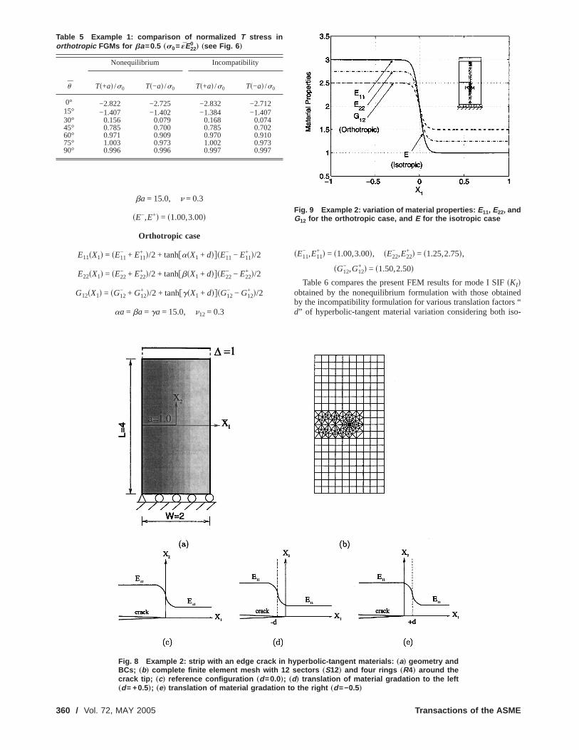
tained by the incompatibility formulation for orthotropic FGMNotice that the two formulations provide similar FEM resultsT stress for each geometric angle. For the isotropic case,T stressat both right and left crack tips changes sign in the range of a
u=30 deg–45 degssee Table 4d, while, for the orthotropic case,
changes sign in the range of angleu=15 deg–30 degssee Tabl5d. Comparison of Tables 4 and 5 indicates that the maorthotropy shows significant effect onT stress in terms of bosign and magnitude.
9.2 Strip With an Edge Crack. Figure 8sad shows an edgcrack of length “a” in a plate, and Fig. 8sbd shows the complemesh discretization using 12 sectorssS12d and four ringssR4d ofelements around the crack tip. Figures 8scd–8sed illustrate thethree considered types of hyperbolic-tangent material gradwith respect to the crack tip: reference configuration, translatithe left, and translation to the right, respectively. The fixed-displacement loading results in a uniform strain«22sX1,X2d= « ina corresponding uncracked structure. The displacement boucondition is prescribed such thatu2=0 along the lower edge au1=0 for the node at the left-hand side. The mesh discretizconsists of 208Q8, 37 T6, and 12T6qpelements, with a total o257 elements and 1001 nodes.
Young’s moduli and shear modulus are hyperbolic-tanfunctions with respect to the globalsX1,X2d Cartesian coordinatewhile Poisson’s ratio is constantsFig. 9d. The following data werused for the FEM analysis:
plane strain, 23 2 Gauss quadrature
a/W= 0.5, L/W= 2.0, « = 0.25, d = s− 0.5 to 0.5d
Isotropic case
EsX1d = sE− + E+d/2 + tanhfbsX1 + ddgsE− − E+d/2
ed-mode SIFs in orthotropic FGMs for ba
KII+ /K0 KI
−/K0 KII− /K0
0.0000 0.6663 0.00000.2176 0.5997 0.24360.4097 0.4150 0.41600.4477 0.1814 0.43790.2906 0.0056 0.28220.0000 0.0000 0.0000
0.0000 0.6663 0.00000.2194 0.5997 0.24270.4111 0.4149 0.41560.4480 0.1809 0.43730.2906 0.0052 0.28230.0000 0.0000 0.0000
Table 4 Example 1: comparison of normalized T stress in iso-tropic FGMs for ba=0.5 „s0= «E0
… „see Fig. 6 …
u
Nonequilibrium Paulino and Dongf48g
Ts+ad /s0 Ts−ad /s0 Ts+ad /s0 Ts−ad /s0
0° −0.896 −0.858 −0.867 −0.87615° −0.773 −0.747 −0.748 −0.76330° −0.434 −0.436 −0.420 −0.44445° 0.036 0.011 0.039 0.01060° 0.513 0.484 0.513 0.49075° 0.868 0.850 0.870 0.85890° 0.994 0.994 1.000 1.000
mix
MAY 2005, Vol. 72 / 359
inedrs “iso-
ba = 15.0, n = 0.3
sE−,E+d = s1.00,3.00d
Orthotropic case
E11sX1d = sE11− + E11
+ d/2 + tanhfasX1 + ddgsE11− − E11
+ d/2
E22sX1d = sE22− + E22
+ d/2 + tanhfbsX1 + ddgsE22− − E22
+ d/2
G12sX1d = sG12− + G12
+ d/2 + tanhfgsX1 + ddgsG12− − G12
+ d/2
aa = ba = ga = 15.0, n12 = 0.3
Table 5 Example 1: comparison of normalized T stress inorthotropic FGMs for ba=0.5 „s0= «E22
0… „see Fig. 6 …
u
Nonequilibrium Incompatibility
Ts+ad /s0 Ts−ad /s0 Ts+ad /s0 Ts−ad /s0
0° −2.822 −2.725 −2.832 −2.71215° −1.407 −1.402 −1.384 −1.40730° 0.156 0.079 0.168 0.07445° 0.785 0.700 0.785 0.70260° 0.971 0.909 0.970 0.91075° 1.003 0.973 1.002 0.97390° 0.996 0.996 0.997 0.997
Fig. 8 Example 2: strip with an edge crack in hyBCs; „b… complete finite element mesh with 12crack tip; „c… reference configuration „d =0.0…
„d = +0.5…; „e… translation of material gradation to the360 / Vol. 72, MAY 2005
sE11− ,E11
+ d = s1.00,3.00d, sE22− ,E22
+ d = s1.25,2.75d,
sG12− ,G12
+ d = s1.50,2.50d
Table 6 compares the present FEM results for mode I SIFsKIdobtained by the nonequilibrium formulation with those obtaby the incompatibility formulation for various translation factod” of hyperbolic-tangent material variation considering both
rbolic-tangent materials: „a… geometry andtors „S12… and four rings „R4… around the… translation of material gradation to the left
Fig. 9 Example 2: variation of material properties: E11, E22, andG12 for the orthotropic case, and E for the isotropic case
pesec; „d
right „d =−0.5…
Transactions of the ASME

EMaretedu-nsse.5.th
veodis
-se
din
opide
thepic
sseea
on ofility,ationensece interials.
dencem-lestIn
n isvedada-e de-e nu-lyple 1.terial
andnrs intermsce
SA-the
tfrom-
sor
n;
sor
nt
ipal
e
is-
tropic and orthotropic FGMs. For the orthotropic case, the Fresults obtained by the nonequilibrium formulation are compwith those obtained by the incompatibility formulation reporby Kim and Paulinof12g. Notice that the two equivalent formlations provide similar FEM results for mode I SIF for each tralation factord. For the isotropic FGMs, the mode I SIF decreawith the translation factord for the range between −0.1 and 0For the orthotropic FGMs, the mode I SIF increases withtranslation factord for the range between −0.5 and −0.1, howeit decreases asd increases further. Table 6 also indicates that mI SIFs for the orthotropic case are smaller than those for thetropic case for each translation factord from −0.5 to −0.1, however, the SIFs for the orthotropic case are greater than thothe isotropic case ford=0 to 0.5.
Table 7 compares the present FEM results forT stress obtaineby the nonequilibrium formulation with those obtained by thecompatibility formulation for various translation factorsd ofhyperbolic-tangent material variation considering both isotrand orthotropic FGMs. Notice that the two formulations provsimilar FEM results, and theT stresses are negative for alltranslation factorsd considered. For both isotropic and orthotroFGMs, theT stress decreases with the translation factord for therange between −0.5 and 0.0, however, it increases asd increasefurther. Table 7 also indicates thatT stress for the orthotropic cais greater than or equal to that for the isotropic case fortranslation factor.
Table 6 Example 2: comparison of mode I SIF „KI… for an edgecrack considering translation „d… of hyperbolic-tangent mate-rial variation „see Fig. 8 …
d
Nonequilibrium Incompatibility
Iso Ortho Iso Orthof12g
−0.5 1.212 1.164 1.186 1.158−0.4 1.211 1.167 1.201 1.163−0.3 1.211 1.175 1.190 1.173−0.2 1.218 1.189 1.209 1.189−0.1 1.231 1.212 1.212 1.217
0 1.030 1.047 1.026 1.0490.1 0.595 0.701 0.588 0.6970.2 0.486 0.615 0.487 0.6140.3 0.451 0.585 0.451 0.5850.4 0.430 0.567 0.430 0.5670.5 0.419 0.554 0.419 0.554
Table 7 Example 2: comparison of T stress for an edge crackconsidering translation „d… of hyperbolic-tangent materialvariation „see Fig. 8 …
d
Nonequilibrium Incompatibility
Iso Ortho Iso Ortho
−0.5 −0.463 −0.393 −0.452 −0.394−0.4 −0.478 −0.407 −0.470 −0.406−0.3 −0.507 −0.434 −0.493 −0.439−0.2 −0.580 −0.499 −0.571 −0.501−0.1 −0.797 −0.686 −0.797 −0.702
0 −1.123 −0.923 −1.181 −0.9620.1 −0.444 −0.364 −0.431 −0.3620.2 −0.218 −0.205 −0.217 −0.2050.3 −0.175 −0.171 −0.175 −0.1710.4 −0.157 −0.157 −0.157 −0.1570.5 −0.152 −0.151 −0.152 −0.152
Journal of Applied Mechanics
d
-s
er,eo-
for
-
ic
ch
10 ConclusionsThis paper provides a critical assessment and comparis
three consistent formulations: nonequilibrium, incompatiband constant-constitutive-tensor formulations. Each formulleads to a consistent form of the interaction integral in the sthat extra terms are added to compensate for the differenresponse between homogeneous and nonhomogeneous maThese extra terms play a key role in ensuring path indepenof the interaction integral for FGMs. In terms of numerical coputations, the nonequilibrium formulation leads to the simpfinal form of the M integral among the three formulations.terms of numerical accuracy, the nonequilibrium formulatioequivalent to the incompatibility formulation, which is obserin numerical examples involving various types of material grtion. The constant-constitutive-tensor formulation requires thrivatives of the actual stress and strain field, and may havmerical accuracy problems with standardC0 elements commonused in the displacement-based FEM, as observed in exam
From numerical investigations, we observe that both magradation and orthotropy have a significant influence on SIFsT stresssi.e., both sign and magnituded, and the crack tip locatioalso shows a significant influence on the fracture parametehyperbolic-tangent materials. We also observe that the extrase.g., nonequilibrium or incompatible termsd ensure convergento target solutionssSIFs orT stressd.
AcknowledgmentsThe authors gratefully acknowledge the support from NA
Ames, Engineering for Complex Systems Program, andNASA-Ames Chief EngineersDr. Tina Panontind through GranNo. NAG 2-1424. They also acknowledge additional supportthe National Science FoundationsNSFd under Grant No. CMS0115954sMechanics and Materials Programd.
Nomenclaturea 5 half crack length
a or aij 5 contracted notation of the compliance tensS or Sijkld for plane stress;i =1,2,6; j=1,2,6
atip or aijtip 5 a or aij evaluated at the crack tip locatio
i , j =1,2,6A 5 a 232 complex matrix
bij 5 contracted notation of the compliance tenfor plane strain;i =1,2,6; j =1,2,6
bijtip 5 bij evaluated at the crack tip location;i , j
=1,2,6B 5 a 232 complex matrix
c11, c22, c12 5 coefficients in the relationship betweenJ andstress intensity factorssKI andKIId
Csud 5 a 232 diagonal matrixCijkl or C 5 constitutive tensor;i , j ,k, l =1,2,3
d 5 translation factor in hyperbolic-tangefunction
d0 5 x1 coordinate of a fixed pointe 5 natural logarithm base,e=2.71828182. . .E 5 Young’s modulus for isotropic materials
E0 5 Young’s modulusE evaluated at the originEtip 5 Young’s modulusE evaluated at the crack t
E11, E22 5 Young’s moduli with respect to the principaxes of orthotropy
E110 , E22
0 5 Young’s moduli E11,E22 evaluated at thorigin
f 5 a point forcef 5 a 231 force vector
f I, f II 5 representative functions for auxiliary dplacements for SIFs
G12 5 shear modulus for orthotropic materials
MAY 2005, Vol. 72 / 361

se
l
l
c-d
o-
nts
nts
is-
se
ra
ra
ra
iths
tesian
on
ls;
ck
ip is
of
mu-
ter-
in
ons
G120 5 shear modulusG12 evaluated at the originG 5 energe release rates
gI, gII 5 representative functions for auxiliary stresfor SIFs
GI 5 mode I energe release rateGII 5 mode II energe release rateH 5 contour integralh 5 a 231 real matrix
Im 5 imaginary part of the complex functionJ 5 path-independentJ integral for the actua
fieldJaux 5 J integral for the auxiliary field
Js 5 J integral for the superimposed fieldssactuaplus auxiliaryd
KI 5 mode I stress intensity factorKII 5 mode II stress intensity factorK0 5 normalizing factor for stress intensity fa
tors, K0= «E0Îpa for the isotropic case anK0= «E22
0 Îpa for the orthotropic caseL 5 length of a plateL 5 a 232 real matrixM 5 interaction integralsM integraldNi 5 shape functions for nodei of an element
N3sud 5 a 232 real matrixmi, ni 5 unit normal vectors on the contour of the d
main integralP 5 a generic propertysCijkl , Sijkl , or «i j d
Psud 5 a 232 diagonal matrixpk 5 coefficients of the asymptotic displaceme
for orthotropic materials;k=1,2qk 5 coefficients of the asymptotic displaceme
for orthotropic materials;k=1,2q 5 weight function in the domain integralr 5 radial direction in polar coordinates
Re 5 real part of the complex functionSijkl or S 5 compliance tensor;i , j ,k, l =1,2,3
Ssud 5 a 232 real matrixT 5 elasticT stresstu 5 representative functions for auxiliary d
placements forT stressts 5 representative functions for auxiliary stres
for T stressui 5 displacements for the actual field;i =1,2
uaux or uiaux 5 a vector for auxiliary displacements;i =1,2W 5 width of a plateW 5 strain energy density
Waux 5 strain energy density for the auxiliary fieldxi 5 local Cartesian coordinates;i =1,2Xi 5 global Cartesian coordinates;i =1,2zk 5 complex variable,zk=xk+ iyk; k=1,2a 5 material nonhomogeneity parameter for g
dation ofE11ak 5 the real part ofmk; k=1,2b 5 material nonhomogeneity parameter for g
dation ofE22 or Ebk 5 the imaginary part ofmk; k=1,2g 5 material nonhomogeneity parameter for g
dation ofG12G 5 contour forJ andM integrals
G0 5 outer contourGs 5 inner contourG+ 5 contour along the upper crack faceG− 5 contour along the lower crack facedi j 5 Kronecker delta;i , j =1,2«i j 5 strains for the actual field;i =1,2,3; j
=1,2,3
362 / Vol. 72, MAY 2005
s
s
-
-
-
«k 5 contracted notation of«i j ; k=1, . . . ,6«aux or «i j
aux 5 a vector for auxiliary strains;i , j =1,2,3u 5 angular direction in polar coordinates w
respect to the local Cartesian coordinate
u 5 the angle of the local Cartesian coordinawith respect to the global Cartescoordinates
um 5 indication of direction of material gradatiwith respect to the crack
k 5 material parameter for isotropic materias3−nd / s1+nd for plane stress and 3−4n forplane strain
ktip 5 material parameterk evaluated at the cratip
mk 5 roots of the characteristic equation;k=1,2mk
tip 5 mk evaluated at the crack tip location;k=1,2
mk 5 complex conjugate ofmk; k=1,2n 5 Poisson’s ratio for isotropic materials
n12, n21 5 Poisson’s ratios for orthotropic materialssk 5 contracted notation ofsi j ; k=1, . . . ,6s0 5 normalizing factor;s0= «E0 for the isotropic
cases0= «E220 for the orthotropic case
si j 5 stresses for the actual fields;i =1,2,3; j=1,2,3
saux or si jaux 5 a vector for auxiliary stresses;i , j =1,2,3
Appendix A: Anisotropic ElasticityThe generalized Hooke’s law for stress-strain relationsh
given by f40g:
«i = aijs j, aij = ajisi, j = 1,2, . . . ,6d sA1d
where the compliance coefficients,aij , are contracted notationsthe compliance tensorSijkl and
«1 = «11, «2 = «22, «3 = «33, «4 = 2«23, «5 = 2«13,
«6 = 2«12
s1 = s11, s2 = s22, s3 = s33, s4 = s23, s5 = s13, s6 = s12
sA2d
For plane stress, theaij components of interest are
aijsi, j = 1,2,6d sA3d
and for plane strain, theaij components are exchanged withbij asfollows:
bij = aij −ai3aj3
a33si, j = 1,2,6d sA4d
Two-dimensional anisotropic elasticity problems can be forlated in terms of the analytic functions,fkszkd, of the complexvariable,zk=xk+ iyk sk=1,2d, i =Î−1, where
xk = x + aky, yk = bkysk = 1,2d sA5d
The parametersak andbk are the real and imaginary parts ofmk=ak+ ibk, which can be determined from the following characistic equationf40g:
a11m4 − 2a16m
3 + s2a12 + a66dm2 − 2a26m + a22 = 0 sA6d
where the rootsmk are always complex or purely imaginaryconjugate pairs asm1,m1;m2,m2.
Appendix B: Representative Functions for SIFsFor orthotropic FGMs, the representative functi1/2 tip
fsr ,u ,a d in Eq. s1d are given byf37g:Transactions of the ASME

fro
aram-
.d
-
he
ons
.
f1I = Î2r/p ReF 1
m1tip − m2
tiphm1tipp2
Îcosu + m2tip sinu
− m2tipp1
Îcosu + m1tip sinujG
f1II = Î2r/p ReF 1
m1tip − m2
tiphp2Îcosu + m2
tip sinu
− p1Îcosu + m1
tip sinujGf2I = Î2r/p ReF 1
m1tip − m2
tiphm1tipq2
Îcosu + m2tip sinu
− m2tipq1
Îcosu + m1tip sinujG
f2II = Î2r/p ReF 1
m1tip − m2
tiphq2Îcosu + m2
tip sinu
− q1Îcosu + m1
tip sinujGwhere Re denotes the real part of the complex function,m1
tip andm2
tip denote crack-tip material parameters, which are obtainedEq. sA6d and taken forbk.0 sk=1,2d, andpk andqk are given by
pk = a11tipsmk
tipd2 + a12tip − a16
tipmktip
qk = a12tipmk
tip +a22
tip
mktip − a26
tip sB1d
respectively. The functionsgsr−1/2,u ,atipd in Eq. s3d are given byf37g:
g11I =
1Î2pr
ReF m1tipm2
tip
m1tip − m2
tipH m2tip
Îcosu + m2tip sinu
−m1
tip
Îcosu + m1tip sinu
JGg11
II =1
Î2prReF 1
m1tip − m2
tipH sm2tipd2
Îcosu + m2tip sinu
−sm1
tipd2
Îcosu + m1tip sinu
JGg22
I =1
Î2prReF 1
m1tip − m2
tipH m1tip
Îcosu + m2tip sinu
−m2
tip
Îcosu + m1tip sinu
JGg22
II =1
Î2prReF 1
m1tip − m2
tipH 1
Îcosu + m2tip sinu
−1
Îcosu + m1tip sinu
JGg12
I =1
Î2prReF m1
tipm2tip
m1tip − m2
tipH 1
Îcosu + m1tip sinu
−1
tip JG
Îcosu + m2 sinuJournal of Applied Mechanics
m
g12II =
1Î2pr
ReF 1
m1tip − m2
tipH m1tip
Îcosu + m1tip sinu
−m2
tip
Îcosu + m2tip sinu
JG sB2d
Notice that, in the earlier expressions, the graded material peters are sampled at the crack tip.
For isotropic FGMs, the representative functionsfsr1/2,u ,atipdfor displacements in Eq.s1d, andgsr−1/2,u ,atipd for stresses in Eqs3d are given in many referencesse.g., Ref.f38gd. The gradematerial parameters are sampled at the crack tip.
Appendix C: Representative Functions forT StressThe presentation follows the Stroh formalismf39g. For othotro
pic FGMs, the representative functionstusln r ,u , f ,atipd in Eq. s4dare given byf39g:
t1u = −
h1
2pln r −
1
2sS11h1 + S12h2d
sC1d
t2u = −
h2
2pln r −
1
2sS21h1 + S22h2d
The parametersSij andhi in Eq. sC1d are the components in t232 matrix Ssud, and the 231 vectorh as follows:
Ssud =2
pRefACsudBTg = FS11 S12
S21 S22G
h = L−1f = Hh1
h2J sC2d
where
A = Fl1tipp1
tip l2tipp2
tip
l1tipq1
tip l2tipq2
tip G, B = F− l1tipm1
tip − l2tipm2
tip
l1tip l2
tip GCsud = Fln s1sud 0
0 ln s2sud G, sksud = cosu + m2tip sinu
L−1 = RefiAB−1g, f = ff,0gT sC3d
in which pktip andqk
tip sk=1,2d are given by Eq.sB1d, andlktip sk
=1,2d is the normalization factor given by the expression
2slktipd2sqk
tip/mktip − mk
tippktipd = 1. sC4d
The representative functionstssr−1,u , f ,atipd in Eq. s6d aregiven by f39g:
t11s = srr
auxcos2 u, t22s = srr
auxsin2 u, t12s = srr
auxsinu cosu
sC5d
where the auxiliary stresses are given byf39g:
srraux=
1
2prnTsudN3sudh, suu
aux= sruaux= 0 sC6d
in which
n = fcosu,sinugT, N3sud = 2 RefBPsudBTgsC7d
Psud = Fm1sud 0
0 m2sud G, mksud =mk
tip cosu − sinu
mktip sinu + cosu
, sk = 1,2d
For isotropic FGMs, the representative functitusln r ,u , f ,atipd in Eq. s4d for displacements, andtssr−1,u , f ,atipdfor stresses in Eq.s6d are given in many referencesse.g., Ref
f41gd. The graded material parameters are sampled at the crack tip.MAY 2005, Vol. 72 / 363

ws
elea
opic
s
rackE J.
lysInt.
Inteive
tresuct.
trop
oden In
nsitUnipp
ally
rac
tingInte
on oract
Tipastic
de
ded
ed-Nu
picrac
tionis o
nar
rackolid
ials
,” J.
nally.–644.neous
Plate
blemlace-
Inter-
,” Int.
thePart
thePart
neous
oge-
n an
arly
s and
ew
ndon
alysisch.,
ded
tressEng.
entsppl.
nts toch.,
in a
d
Pro-
rackThreental
Referencesf1g Knowles, J. K., and Sternberg, E., 1972, “On a Class of Conservation La
Linearized and Finite Elastostatics,” Arch. Ration. Mech. Anal.,44s2d, pp.187–211.
f2g Budiansky, B., and Rice, J. R., 1973, “Conservation Laws and Energy-RRates,” ASME J. Appl. Mech.,40s1d, pp. 201–203.
f3g Chang, J. H., and Chien, A. J., 2002, “Evaluation of M-Integral for AnisotrElastic Media With Multiple Defects,” Int. J. Fract.,114s3d, pp. 267–289.
f4g Kanninen, M. F., and Popelar, C. H., 1985,Advanced Fracture Mechanic,Oxford University Press, New York.
f5g Yau, J. F., Wang, S. S., and Corten, H. T., 1980, “A Mixed-Mode CAnalysis of Isotropic Solids Using Conservation Laws of Elasticity,” ASMAppl. Mech., 47s2d, pp. 335–341.
f6g Wang, S. S., Corten, H. T., and Yau, J. F., 1980, “Mixed-Mode Crack Anaof Rectilinear Anisotropic Solids Using Conservation Laws of Elasticity,”J. Fract., 16s3d, pp. 247–259.
f7g Yau, J. F., 1979, “Mixed-Mode Fracture Analysis Using a Conservationgral,” PhD thesis, Department of Theoretical and Applied Mechanics, Unsity of Illinois at Urbana-Champaign.
f8g Dolbow, J., and Gosz, M., 2002, “On the Computation of Mixed-Mode SIntensity Factors in Functionally Graded Materials,” Int. J. Solids Str39s9d, pp. 2557–2574.
f9g Rao, B. N., and Rahman, S., 2003, “Mesh-Free Analysis of Cracks in IsoFunctionally Graded Materials,” Eng. Fract. Mech.,70s1d, pp. 1–27.
f10g Kim, J.-H., and Paulino, G. H., 2003, “An Accurate Scheme for Mixed-MFracture Analysis of Functionally Graded Materials Using the Interactiotegral and Micromechanics Models,” Int. J. Numer. Methods Eng.,58s10d, pp.1457–1497.
f11g Kim, J.-H., and Paulino, G. H., 2003, “T-Stress, Mixed-Mode Stress InteFactors, and Crack Initiation Angles in Functionally Graded Materials: Afied Approach Using the Interaction Integral Method,” Comput. Methods AMech. Eng., 192s11–12d, pp. 1463–1494.
f12g Kim, J.-H., and Paulino, G. H., 2004, “T-Stress in Orthotropic FunctionGraded Materials: Lekhnitskii and Stroh Formalisms,” Int. J. Fract.,126s4d,pp. 345–389.
f13g Eischen, J. W., 1987, “Fracture of Non-Homogeneous Materials,” Int. J. F34s1d, pp. 3–22.
f14g Gu, P., Dao, M., and Asaro, R. J., 1997, “A Simplified Method for Calculathe Crack-Tip Field of Functionally Graded Materials Using the Domaingral,” ASME J. Appl. Mech.,34s1d, pp. 1–17.
f15g Anlas, G., Santare, M. H., and Lambros, J., 2000, “Numerical CalculatiStress Intensity Factors in Functionally Graded Materials,” Int. J. F104s2d, pp. 131–143.
f16g Marur, P. R., and Tippur, H. V., 2000, “Numerical Analysis of Crack-Fields in Functionally Graded Materials With a Crack Normal to the ElGradient,” Int. J. Solids Struct.,37s38d, pp. 5353–5370.
f17g Bao, G., and Cai, H., 1997, “Delamination Cracking in Functionally GraCoating/Metal Substrate Systems,” Acta Mech.,45s3d, pp. 1055–1066.
f18g Bao, G., and Wang, L., 1995, “Multiple Cracking in Functionally GraCeramic/Metal Coatings,” Int. J. Solids Struct.,32s19d, pp. 2853–2871.
f19g Kim, J.-H., and Paulino, G. H., 2002, “Finite Element Evaluation of MixMode Stress Intensity Factors in Functionally Graded Materials,” Int. J.mer. Methods Eng.,53s8d, pp. 1903–1935.
f20g Kim, J.-H., and Paulino, G. H., 2002, “Mixed-Mode Fracture of OrthotroFunctionally Graded Materials Using Finite Elements and the Modified CClosure Method,” Eng. Fract. Mech.,69s14–16d, pp. 1557–1586.
f21g Kim, J.-H., and Paulino, G. H., 2003, “Mixed-Mode J-Integral Formulaand Implementation Using Graded Finite Elements for Fracture AnalysNonhomogeneous Orthotropic Materials,” Mech. Mater.,35s1–2d, pp. 107–128.
f22g Williams, M. L., 1957, “On the Stress Distribution at the Base of a StatioCrack,” ASME J. Appl. Mech.,24s1d, pp. 109–114.
f23g Becker, T. L., Jr., Cannon, R. M., and Ritchie, R. O., 2001, “Finite CKinking and T-Stresses in Functionally Graded Materials,” Int. J. SStruct., 38s32–33d, pp. 5545–5563.
f24g Erdogan, F., 1995, “Fracture Mechanics of Functionally Graded Mater
364 / Vol. 72, MAY 2005
in
se
is
-r-
s,
ic
-
y-l.
t.,
-
f.,
d
-
k
f
y
s
,”
Composites Eng.,5s7d, pp. 753–770.f25g Noda, N., 1999, “Thermal Stresses in Functionally Graded Materials
Therm. Stresses,22s4–5d, pp. 477–512.f26g Paulino, G. H., Jin, Z. H., and Dodds, R. H., Jr., 2003, “Failure of Functio
Graded Materials.”Comprehensive Structural Integrity, B. Karihaloo and WG. Knauss, eds., Elsevier Science, New York, Vol. 2, Chap. 13, pp. 607
f27g Delale, F., and Erdogan, F., 1983, “The Crack Problem for a NonhomogePlane,” ASME J. Appl. Mech.,50s3d, pp. 609–614.
f28g Erdogan, F, and Wu, B. H., 1997, “The Surface Crack Problem for aWith Functionally Graded Properties,” ASME J. Appl. Mech.,64s3d, pp. 449–456.
f29g Chan, Y.-S., Paulino, G. H., and Fannjiang, A. C., 2001, “The Crack Profor Nonhomogeneous Materials Under Antiplane Shear Loading—A Dispment Based Formulation,” Int. J. Solids Struct.,38s17d, pp. 2989–3005.
f30g Delale, F., and Erdogan, F., 1988, “On the Mechanical Modeling of anfacial Region in Bonded Half-Planes,” ASME J. Appl. Mech.,55s2d, pp. 317–324.
f31g Gu, P., and Asaro, R. J., 1997, “Cracks in Functionally Graded MaterialsJ. Solids Struct.,34s1d, pp. 1–17.
f32g Shbeeb, N. I., Binienda, W. K., and Kreider, K. L., 1999, “Analysis ofDriving Forces for Multiple Cracks in an Infinite Nonhomogeneous Plate,I: Theoretical Analysis,” ASME J. Appl. Mech.,66s2d, pp. 492–500.
f33g Shbeeb, N. I., Binienda, W. K., and Kreider, K. L., 1999, “Analysis ofDriving Forces for Multiple Cracks in an Infinite Nonhomogeneous Plate,II: Numerical Solutions,” ASME J. Appl. Mech.,66s2d, pp. 501–506.
f34g Honein, T., and Herrmann, G., 1997, “Conservation Laws in NonhomogePlane Elastostatics,” J. Mech. Phys. Solids,45s5d, pp. 789–805.
f35g Ozturk, M., and Erdogan, F., 1997, “Mode I Crack Problem in an Inhomneous Orthotropic Medium,” Int. J. Eng. Sci.,35s9d, pp. 869–883.
f36g Ozturk, M., and Erdogan, F., 1999, “The Mixed Mode Crack Problem iInhomogeneous Orthotropic Medium,” Int. J. Fract.,98s3–4d, pp. 243–261.
f37g Sih, G. C., Paris, P. C., and Irwin, G. R., 1965, “On Cracks in RectilineAnisotropic Bodies,” Int. J. Fract. Mech.,1s2d, pp. 189–203.
f38g Eftis, J., Subramonian, N., and Liebowitz, H., 1977, “Crack Border AtresDisplacement Equations Revisited,” Eng. Fract. Mech.,9s1d, pp. 189–210.
f39g Ting, C. T. C., 1996,Anisotropic Elasticity: Theory and Applications, OxfordUniversity Press, Oxford.
f40g Lekhnitskii, S. G., 1968,Anisotropic Plates, Gordon and Breach Science, NYork.
f41g Michell, J. H., 1900, “Elementary Distributions of Plane Stress,” Proc. LoMath. Soc., 32, pp. 35–61.
f42g Rice, J. R., 1968, “A Path-Independent Integral and the Approximate Anof Strain Concentration By Notches and Cracks,” ASME J. Appl. Me35s2d, pp. 379–386.
f43g Kim, J.-H., 2003, “Mixed-Mode Crack Propagation in Functionally GraMaterials,” PhD thesis, University of Illinois at Urbana-Champaign.
f44g Paulino, G. H., and Kim, J.-H., 2004, “A New Approach to Compute T-Sin Functionally Graded Materials Using the Interaction Integral Method,”Fract. Mech.,71s13–14d, pp. 1907–1950.
f45g Kim, J.-H., and Paulino, G. H., 2002, “Isoparametric Graded Finite Elemfor Nonhomogeneous Isotropic and Orthotropic Materials,” ASME J. AMech., 69s4d, pp. 502–514.
f46g Santare, M. H., and Lambros, J., 2000, “Use of Graded Finite ElemeModel the Behavior of Nonhomogeneous Materials,” ASME J. Appl. Me67s4d, pp. 819–822.
f47g Konda, N., and Erdogan, F., 1994, “The Mixed Mode Crack ProblemNonhomogeneous Elastic Medium,” Eng. Fract. Mech.,47s4d, pp. 533–545.
f48g Paulino, G. H., and Dong, Z.sunpublishedd.f49g Cook, R. D., Malkus, D. S., Plesha, M. E., and Witt, R. J., 2001,Concepts an
Applications of Finite Element Analysis, 4th ed., Wiley, New York.f50g Wawrzynek, P. A., 1987, “Interactive Finite Element Analysis of Fracture
cesses: An Integrated Approach,” MS thesis, Cornell University.f51g Wawrzynek, P. A., and Ingraffea, A. R., 1991, “Discrete Modeling of C
Propagation: Theoretical Aspects and Implementation Issues in Two andDimensions,” Report 91-5, School of Civil Engineering and EnvironmeEngineering, Cornell University.
Transactions of the ASME


