Considerations for CDR Bandwidth Proposal -...
15
Considerations for CDR Bandwidth Proposal Fernando De Bernardinis, Carlo Pinna Marvell Italy
Transcript of Considerations for CDR Bandwidth Proposal -...

Considerations for CDR Bandwidth ProposalFernando De Bernardinis, Carlo Pinna
Marvell Italy
Supporters
• Ali Ghiasi - Ghiasi Quantum LLC
• Venugopal Balasubramonian – Marvell
• Vipul Bhatt – Inphi
• Upen Reddy Kareti – Cisco
• Jane Lim - Cisco
14-Mar-16 2

Comments addressed
• Comment 93 CRU BW for 400Gbase-DR4
• Comment 94 stress receiver sensitivity for 400Gbase-DR4
• Comment 95 CRU BW for CDAUI-8
• Comment 96 stress receiver sensitivity for CDAUI-8
• Comment 103 CRU BW for CDAUI-8
• Comment 104, 105 for clause 120D
• Comment 106 module stress receiver sensitivity for CDAUI-8
• Comment 109-115 for clause 120E
14-Mar-16 3
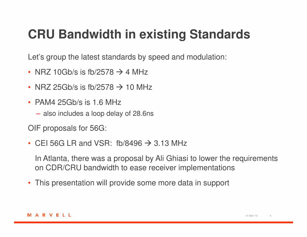
CRU Bandwidth in existing Standards
Let’s group the latest standards by speed and modulation:
• NRZ 10Gb/s is fb/2578 � 4 MHz
• NRZ 25Gb/s is fb/2578 � 10 MHz
• PAM4 25Gb/s is 1.6 MHz
– also includes a loop delay of 28.6ns
OIF proposals for 56G:
• CEI 56G LR and VSR: fb/8496 � 3.13 MHz
In Atlanta, there was a proposal by Ali Ghiasi to lower the requirements on CDR/CRU bandwidth to ease receiver implementations
• This presentation will provide some more data in support
14-Mar-16 4
CDR Loop and rms Jitter
• Let’s consider a number of TX PLL phase noise plots as available from published material
– As published at ISSCC (2013, 2014, 2015 and 2016)
• The rms jitter is computed in several ways:
– Use a first order high pass filter, golden PLL with no latency
– Use a realistic CDR with implementation latency
• Second order loop, 10ns latency, pole separation 5x or complex with chi=0.707
• Support the proposal to set a CDR bandwidth somewhere between 2 and 4 MHz
– Not only golden PLL improvements are negligible, but realistic CDR
implementation actually may deliver worse performance with larger
bandwidths
14-Mar-16 5

RX Jitter and CDR Loop
• CDR loop tracks TX phase
– Jitter is rejected with a high pass transfer function
• Higher bandwidth improves performance
– Exploit corner frequency to lower requirements on TX
• Latency limits bandwidth related improvements
– Peaking after -3dB corner Jitter TF with corner at 8 MHz vs. latency
– DSP particularly sensitive to it
14-Mar-16 60
5
10
15
20
25
30
0
5
10
15
-40
-30
-20
-10
0
10
20
Frequency (MHz)
Loop Latency (ns)
Jitt
er
TF
(d
B)
106
107
-30
-25
-20
-15
-10
-5
0
5
10
Frequency
dB
Jitter Transfer Function
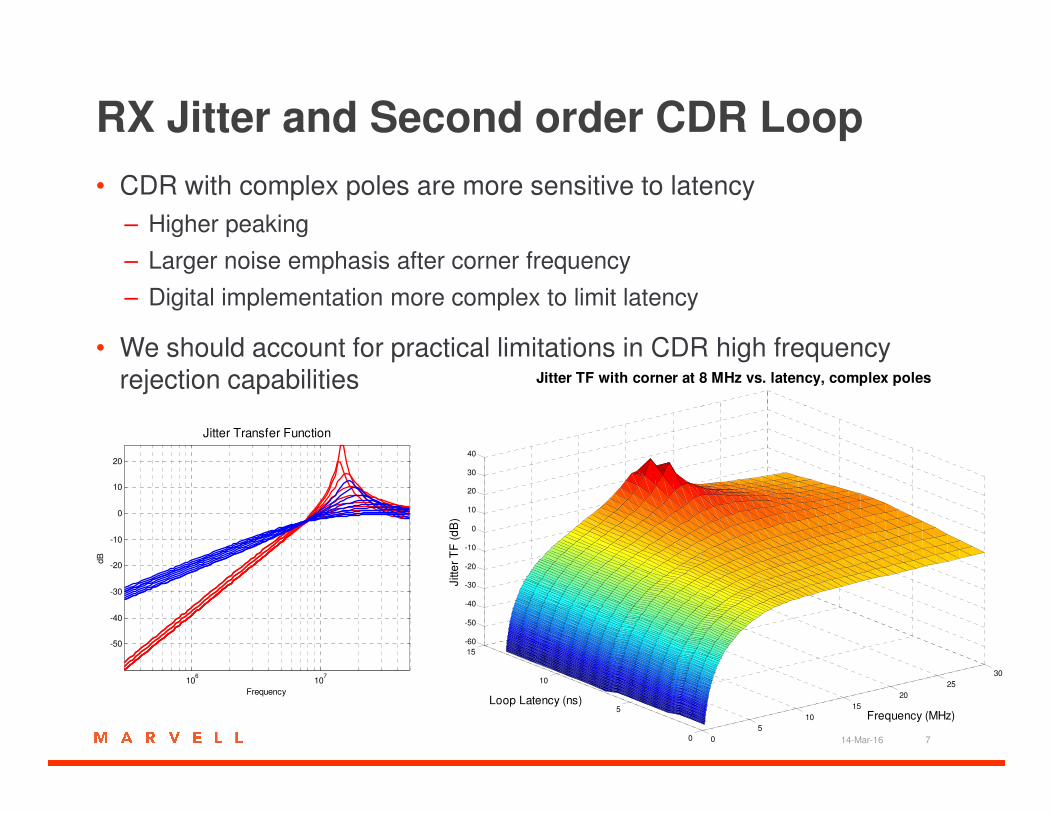
RX Jitter and Second order CDR Loop
• CDR with complex poles are more sensitive to latency
– Higher peaking
– Larger noise emphasis after corner frequency
– Digital implementation more complex to limit latency
• We should account for practical limitations in CDR high frequency rejection capabilities Jitter TF with corner at 8 MHz vs. latency, complex poles
14-Mar-16 70
5
10
15
20
25
30
0
5
10
15
-60
-50
-40
-30
-20
-10
0
10
20
30
40
Frequency (MHz)
Loop Latency (ns)
Jitte
r T
F (
dB
)
106
107
-50
-40
-30
-20
-10
0
10
20
Frequency
dB
Jitter Transfer Function
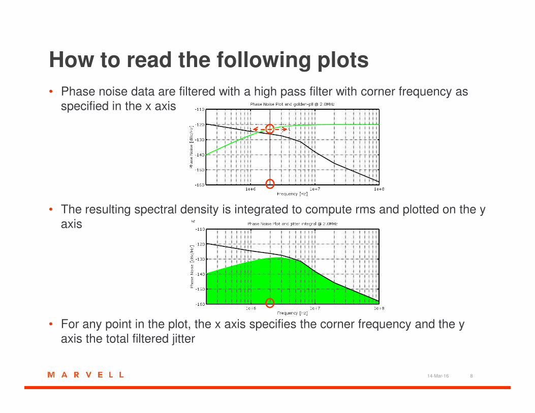
How to read the following plots
• Phase noise data are filtered with a high pass filter with corner frequency as
specified in the x axis
• The resulting spectral density is integrated to compute rms and plotted on the y • The resulting spectral density is integrated to compute rms and plotted on the y
axis
• For any point in the plot, the x axis specifies the corner frequency and the y
axis the total filtered jitter
14-Mar-16 8
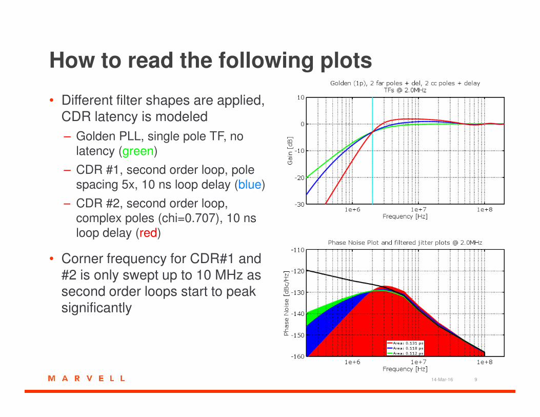
How to read the following plots
• Different filter shapes are applied, CDR latency is modeled
– Golden PLL, single pole TF, no
latency (green)
– CDR #1, second order loop, pole
spacing 5x, 10 ns loop delay (blue)
– CDR #2, second order loop, – CDR #2, second order loop,
complex poles (chi=0.707), 10 ns
loop delay (red)
• Corner frequency for CDR#1 and #2 is only swept up to 10 MHz as second order loops start to peak significantly
14-Mar-16 9
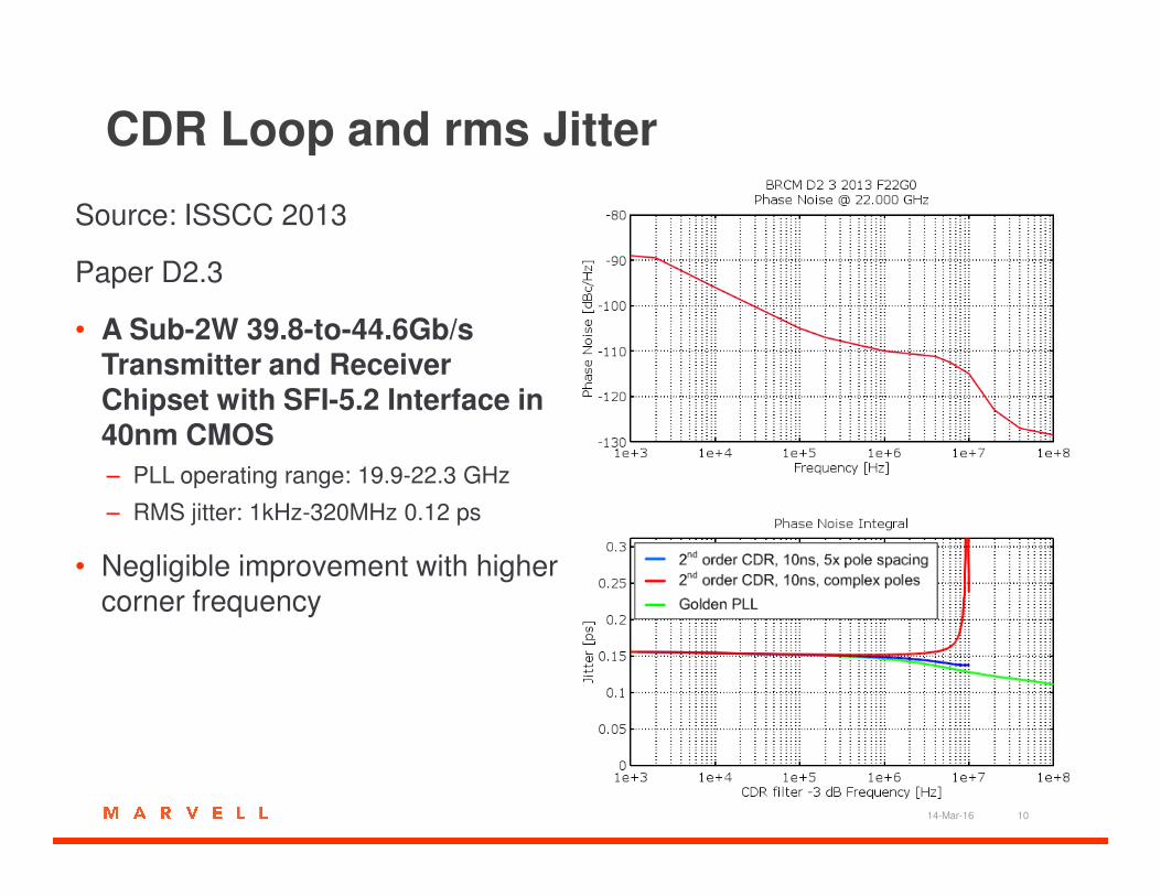
CDR Loop and rms Jitter
Source: ISSCC 2013
Paper D2.3
• A Sub-2W 39.8-to-44.6Gb/s Transmitter and Receiver Chipset with SFI-5.2 Interface in 40nm CMOS40nm CMOS
– PLL operating range: 19.9-22.3 GHz
– RMS jitter: 1kHz-320MHz 0.12 ps
• Negligible improvement with higher corner frequency
14-Mar-16 10
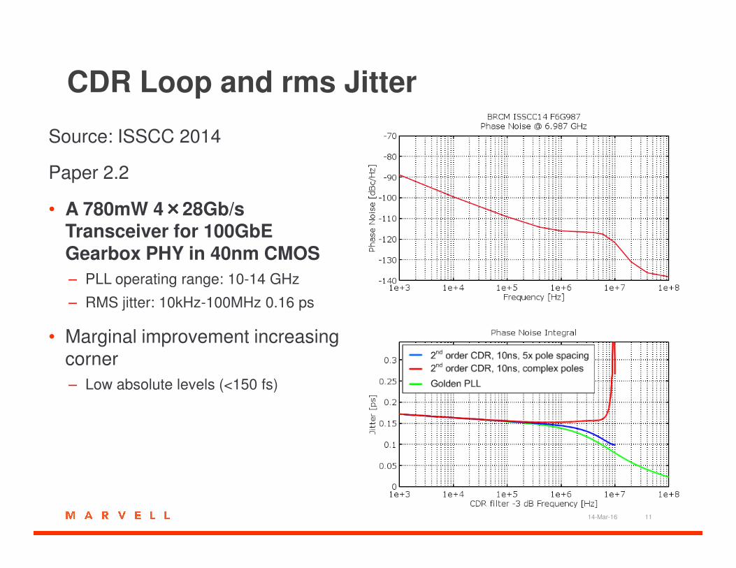
CDR Loop and rms Jitter
Source: ISSCC 2014
Paper 2.2
• A 780mW 4××××28Gb/s Transceiver for 100GbE Gearbox PHY in 40nm CMOS
– PLL operating range: 10-14 GHz– PLL operating range: 10-14 GHz
– RMS jitter: 10kHz-100MHz 0.16 ps
• Marginal improvement increasing corner
– Low absolute levels (<150 fs)
14-Mar-16 11
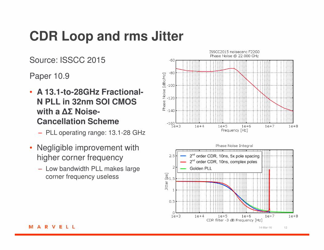
CDR Loop and rms Jitter
Source: ISSCC 2015
Paper 10.9
• A 13.1-to-28GHz Fractional-N PLL in 32nm SOI CMOS with a ∆Σ Noise-Cancellation Scheme Cancellation Scheme
– PLL operating range: 13.1-28 GHz
• Negligible improvement with higher corner frequency
– Low bandwidth PLL makes large
corner frequency useless
14-Mar-16 12

CDR Loop and rms Jitter
Source: ISSCC 2016
Paper 3.4
• A 40/50/100Gb/s PAM-4 Ethernet Transceiver in 28nm CMOS
– PLL operating range: 9.9-15.5 GHz– PLL operating range: 9.9-15.5 GHz
– RMS jitter: 1kHz-100MHz 0.181 ps
• Marginal improvement increasing corner
– Low absolute levels (<150 fs)
14-Mar-16 13
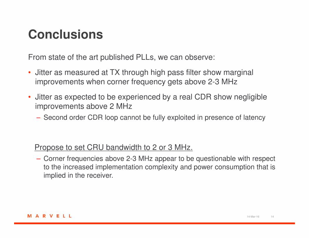
Conclusions
From state of the art published PLLs, we can observe:
• Jitter as measured at TX through high pass filter show marginal improvements when corner frequency gets above 2-3 MHz
• Jitter as expected to be experienced by a real CDR show negligible improvements above 2 MHz
– Second order CDR loop cannot be fully exploited in presence of latency– Second order CDR loop cannot be fully exploited in presence of latency
Propose to set CRU bandwidth to 2 or 3 MHz.
– Corner frequencies above 2-3 MHz appear to be questionable with respect
to the increased implementation complexity and power consumption that is
implied in the receiver.
14-Mar-16 14

Thanks.Thanks.
14-Mar-16 15