CONOCOPHILLIPS AUSTRALIA PTY LTD A TOTAL … · CONOCOPHILLIPS AUSTRALIA PTY LTD A ... combination...
11
A TOTAL INTEGRATED APPROACH CONOCOPHILLIPS AUSTRALIA PTY LTD A case study describing how total plant turbomachinery control was used to maximize production at the ConocoPhillips Bayu-Undan project.
Transcript of CONOCOPHILLIPS AUSTRALIA PTY LTD A TOTAL … · CONOCOPHILLIPS AUSTRALIA PTY LTD A ... combination...

A TOTAL INTEGRATED APPROACH
C O N O C O P H I L L I P S A U S T R A L I A P T Y LT D
A case study describing how total plant turbomachinery
control was used to maximize production at the
ConocoPhillips Bayu-Undan project.

2
IntroductionThe Bayu-Undan platform is a unique world-scale offshore gas processing platform handling over 1.1 billion cubic feet per day
of gas. The platform extracts over 115,000 barrels per day of combined condensate, propane, and butane and produces over
950 MMSFCD of dry natural gas.
The project was implemented in two phases. Phase 1, achieving production in early 2004, involved processing the wet gas
to separate and store condensate, propane, and butane; and reinjecting dry gas back into the reservoir. Phase 2, realizing
production in early 2006, involved exporting the gas via pipeline to a liquefied natural gas (LNG) facility near Darwin, Australia.
Process OverviewGas from the wellheads is fed to the production separator where heavier hydrocarbons drop out as liquids. The glycol
contactors remove water entrained in the gas stream. The gas is further processed by the cold process trains to remove
condensate. The liquid from the production separator feeds the second stage separator, where light hydrocarbons flash out
and feed the second stage of the flash gas compressor and the remaining liquid is further processed by the fractionators.
Light gas from the fractionators is compressed by the flash gas compressors and sent back to the production separator. Gas
from the re-compressors is compressed for reinjection into the reservoir and/or export to the pipeline.
Figure 2: Process Flow Diagram
3
The critical turbomachinery driving the process include the following:
• Two parallel single-stage turbo-expander/re-compressor trains
• Two parallel gas turbine-driven two-stage compressors (7.5 megawatts each)
• Three parallel gas turbine-driven three-stage compressors (23 megawatts each)
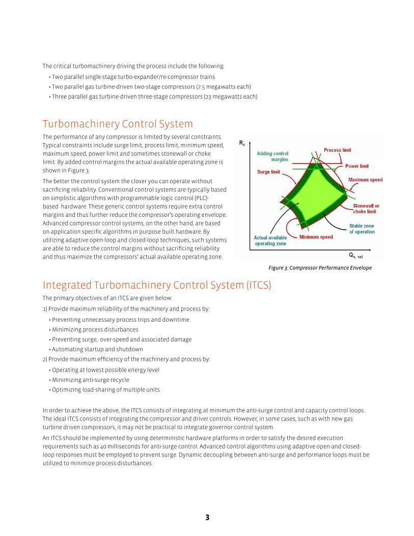
Turbomachinery Control SystemThe performance of any compressor is limited by several constraints.
Typical constraints include surge limit, process limit, minimum speed,
maximum speed, power limit and sometimes stonewall or choke
limit. By added control margins the actual available operating zone is
shown in Figure 3.
The better the control system the closer you can operate without
sacrificing reliability. Conventional control systems are typically based
on simplistic algorithms with programmable logic control (PLC)-
based hardware. These generic control systems require extra control
margins and thus further reduce the compressor’s operating envelope.
Advanced compressor control systems, on the other hand, are based
on application specific algorithms in purpose built hardware. By
utilizing adaptive open-loop and closed-loop techniques, such systems
are able to reduce the control margins without sacrificing reliability
and thus maximize the compressors’ actual available operating zone.
Figure 3: Compressor Performance Envelope
Integrated Turbomachinery Control System (ITCS)The primary objectives of an ITCS are given below:
1) Provide maximum reliability of the machinery and process by:
• Preventing unnecessary process trips and downtime
• Minimizing process disturbances
• Preventing surge, over-speed and associated damage
• Automating startup and shutdown
2) Provide maximum efficiency of the machinery and process by:
• Operating at lowest possible energy level
• Minimizing anti-surge recycle
• Optimizing load-sharing of multiple units
In order to achieve the above, the ITCS consists of integrating at minimum the anti-surge control and capacity control loops.
The ideal ITCS consists of integrating the compressor and driver controls. However, in some cases, such as with new gas
turbine driven compressors, it may not be practical to integrate governor control system.
An ITCS should be implemented by using deterministic hardware platforms in order to satisfy the desired execution
requirements such as 40 milliseconds for anti-surge control. Advanced control algorithms using adaptive open-and closed-
loop responses must be employed to prevent surge. Dynamic decoupling between anti-surge and performance loops must be
utilized to minimize process disturbances.

4
Conventional ApproachThe conventional approach to designing multiple
turbomachinery control systems is to either resort to
original equipment manufacturer (OEM)-supplied control
systems or to implement the turbomachinery controls in
the distributive control system (DCS).
Another approach is to integrate the turbomachinery
control system with the emergency shutdown (ESD)
system. All three approaches have inherent deficiencies as
discussed below.
(PLC)-based systems have been proven inadequate for
anti-surge and performance control. With different
OEMs for each set of machines, the result is different
PLC systems utilizing various algorithms and control
strategies. This makes integration between the systems
virtually impossible.
Figure 4: Conventional Approach
Utilizing the DCS for anti-surge control has also proven to be inadequate. Despite this, the DCS approach appears attractive
as it greatly reduces the number of control interfaces. However, the success of this approach relies heavily on DCS engineers’
limited turbomachinery experience.
The last approach is to integrate the turbomachinery control system with the ESD system. This approach is being promoted
as economically attractive but has several flaws. Firstly, this approach violates the practice of keeping basic process control
systems and ESD systems separate. Process control systems are designed to keep process running while ESD systems are
designed to trip the plant. Typically, this approach utilizes triple modular redundant (TMR) systems and the perception being
promoted is that the highest availability is realized. In reality the ESD system, while achieving the desired safety level of the
system, sacrifices the process availability by causing unnecessary process trips. Often too much focus is given to control
system hardware and not the quality of control. These systems fall short in adequately integrating anti-surge, load-sharing
and performance control to maximize availability of the turbomachinery. A properly designed ITCS (as described in the
following sections) actually minimizes the safety integrity level requirements through improved basic process control1.
Total Integrated ApproachThis approach involves determining the overall process control needs with respect to turbomachinery control for all
machines. This involves providing an ITCS for each service focused on meeting the performance control objectives for the
process. For practical purposes the ITCS for both flash gas and reinjection services included the anti-surge and performance
control loops while the governor control loops remained with the OEM.

5
As the machines are interconnected
in the process, it is prudent to look
at how further integration between
machines can be beneficial. Such
systems can be integrated with
each other by internal controller
communication to allow for feed
forward control actions where
necessary.
This approach requires extensive
field-proven experience in designing,
engineering and commissioning
various turbomachinery control
systems for different applications.
This integrated approach served
the basis for Compressor Controls
Corporation (CCC) design when
supplying ITCS solutions for all
machines.
Figure 5: Total Integrated Approach
Project ExecutionThe design phase for the facility involved ConocoPhillips experts, EPC TIGA (joint venture between Fluor Daniel and
WorleyParsons), the OEMs (Sulzer, Dresser Rand and GE Rotoflow), and the ITCS provider (CCC). The execution of the project
required CCC’s design effort to include:
• Review preliminary process control philosophy
• Provide preliminary control system design report
• Participate in setting up the dynamic simulation effort
• Review preliminary dynamic simulation test results
• Provide final control system design report
• Review final dynamic simulation results
• Provide final ITCS engineering manual
• Commissioning recommendations
Ideal interaction between all parties driven by ConocoPhillips was instrumental in developing and testing the ITCS strategies.
Overall Turbomachinery Control Design BasisThe basis for each ITCS design focused on meeting the overall process control objectives.
The primary control objectives identified during the preliminary engineering phase were:
• Provide maximum protection for each machine
• Maximize liquids production
• Maintain gas for reinjection/export
The secondary control objectives that were identified included:
• Necessary limiting control loops for each machine
• Balance the load between the machines to provide equal protection

6
The final control elements available to the ITCS were identified to be:
• Flash gas compressors speed and anti-surge valves
• Turbo expanders inlet guide vanes (IGV)
• Turbo expanders joint trench (JT) valves
• Re-compressors anti-surge valves
• Reinjection/export compressors speed and anti-surge valves
Flash Gas Compressor ITCSThe primary objective of the flash gas compressor is to compress
gas from the de-ethanizer and gas from the second stage separator.
In order to maximize liquids production the first stage suction
pressure and the interstage pressure of the flash gas compressor
needed to be precisely controlled. This could only be done by a
combination of operation of the anti-surge valves and the gas
turbine speed. The challenge in real time is determining which
pressure will be controlled by speed while the remaining one
via the anti-surge valve. As the flow from the de-ethanizer and
flow from the second stage are both very dynamic the need for
optimized performance control was identified. The performance
control loops within the ITCS were required to control speed and
the anti-surge valve to meet the suction and interstage pressures
based on efficiency, or in other words, least recycle. This method of
optimized performance control ensured that unnecessary recycling
was avoided.
Figure 6: ITCS for Flash Gas Compressors
In summary, the flash gas compressors ITCS objectives were as follows:
• Provide invariant anti-surge control
• Optimized first stage and interstage pressure control
• Equidistant to surge load-sharing
• Decoupling between anti-surge and performance control loops
• Decoupling between anti-surge control loops
• Limiting control loops
Turbo-Expander/Re-Compressor ITCSThe primary objective of the cold part of the process (turbo-expander/re-compressor trains) is to maximize liquids production.
In conventional expander control systems speed is not typically controlled. Therefore during an upset turbo-expander
speed may exceed allowable limits. Conventional control systems prevent over-speed based on primitive and often indirect
methods, such as limiting the IGV position, limiting differential pressure across the expander or split range control between
IGV and JT valve. These methods sacrifice liquids production.
Conventional control systems also ignore the importance of providing adequate anti-surge control for the re-compressor.
However protecting the re-compressor against surge is just as critical as for any other compressor.

7
CCC’s patented ITCS for turbo-expander/re-
compressors provides maximum protection
and utilizes control strategies that maximize
liquids production2. The JT valve is therefore
used when absolutely necessary.
CCC’s patented over-speed prevention
strategy is based on direct control of speed,
as well as acting on the re-compressor’s anti-
surge valve to load up the train, then closing
the IGV if speed continues to increase. This
strategy maximizes utilization of the expander
and minimizes use of the JT valve, thereby
maximizing liquids production.
Load-sharing between turbo-expander/ re-
compressor trains is also critical. Operating
close to surge demands equal protection (i.e.
equidistant to surge load-sharing). However,
operating far away from surge demanded
shifting the load-sharing focus from the re-
compressor to the turbo-expander.
Figure 7: ITCS for Turboexpander/Recompressors
Equal efficiency across the expanders was desired when operating away from surge. As a result, an optimized load-sharing
strategy was developed, providing equal surge protection across the re-compressor when in the vicinity of surge and equal
efficiency across the turbo-expanders when far away from surge.
Unnecessary turbo-expander trips, in practice, greatly affect the process. CCC’s patented JT valve prepositioning algorithm
reduces the severity of the trip on the process. CCC “prepositions” the JT valve based on the capacity equivalent the turbo-
expander’s throughput immediately prior to trip. This strategy keeps the process online and minimizes temperature
excursions in the low temperature separator (LTS) and in effect maximizes liquids production. The loss of one turbo-expander
requires the running train to take as much load as possible. The running train switches to flow control while the JT valve
controls the production separator pressure to minimize loss of liquids production. This in effect minimizes loss of liquids
production.
In summary, the turbo-expander/re-compressors ITCS objectives were as follows:
• Maintain production separator pressure
• Optimized load-sharing strategy
• Equidistant to surge load-sharing
• Decoupling between anti-surge and performance control loops
• Limiting control loops
Reinjection/Export ITCSThe primary objective of the reinjection/export compressors is to deliver gas at a suitable pressure and flowrate for either
reinjection or export. More than six operating modes were identified depending on whether the upstream expander/re-
compressors were online and the export requirements. This required CCC to translate these operating modes into control
modes for each individual compressor. The control modes were defined as follows:
• Mode A. Participates in a load-sharing scheme based on controlling suction manifold pressure, applicable when the
compressor operates in either high speed mode (discharge pressure = 310 barg) or low speed mode (discharge pressure =
190 barg). One, two or all three compressors may operate in this mode.

8
• Mode B. Non-load-sharing (stand-alone) choke control scheme, applicable only when the compressors operate in low
speed mode (discharge pressure = 190 barg). One or a maximum of two export/reinjection compressors may operate in this
mode.
• Mode C. Non-load-sharing (stand-alone) compressor suction pressure control scheme, applicable when the compressor
operates in low- or high-speed mode. Only one compressor at a time may operate in this mode.
Using one of the operating modes as an example the control modes were defined as show in Figure 8, whereby one machine is
dedicated for export while the other machines for reinjection.
Figure 8: Reinjection/Export Compressor Normal Export Mode
Based on the complex operating modes, unique challenges for the reinjection/export compressors ITCS were observed. The
importance of not only anti-surge control but also operating one or more of the machines in choke region was of significant
concern.
The anti-surge control requirements for each compressor required providing adequate surge protection for each stage while
utilizing one anti-surge valve. CCC’s experience in multiple anti-surge controllers sharing a single valve was utilized.
The requirements for anti-choke control were identified early in the design phase. CCC’s knowledge and experience were
utilized to determine whether independent anti-choke control was required or integration within the anti-surge controllers
was adequate. Anti-surge controllers with integrated anti-choke control were provided.
The integrated anti-surge and anti-choke control required an optimized load-sharing strategy. When the machines are close
to surge, the equidistant to surge-load-sharing was desired; yet when away from surge, or in other words close to choke,
equidistant to choke was required. This optimized load-sharing strategy and provided maximum protection for all parallel
machines.

9
In summary, the reinjection/export compressors ITCS
objectives were as follows:
• Maintain suction pressure
• Provide integrated anti-surge and anti-choke
control for each stage
• Optimized load-sharing strategy
• Decoupling between anti-surge and performance
control loops
• Limiting loops
The Role of DynamicSimulationDynamic simulation played a pivotal role during the
design phase of the project. The design simulation
package used was Hysys, which included models of
CCC controls.
With the help of CCC the project, team refined the
CCC models to ensure that models emulated the ITCS
system in this project. Once the system was setup, the
dynamic simulation was instrumental in testing the
control strategies listed above.
The dynamic simulation exercise provided a starting
point for setting up each ITCS and the necessary
interactions. The control strategies developed in
the ITCS for each machine were tested and verified
throughout the simulation process.
The extensive testing provided a benchmark for
system performance. The overall dynamic simulation
process provided no surprises during commissioning
and contributed to shorter startup time.
Figure 9: ITCS for Reinjection/Export Compressors
Total Integrated Approach in ActionThe total integrated approach proved extremely beneficial. Figure 10 illustrates the total plant turbomachinery control,
consisting of the ITCS for flash gas, turbo-expander and reinjection/export services.
One of the benefits realized by this approach was demonstrated during the design phase, when it was recognized that the
flash gas compressors would potentially run into overload condition while running at maximum speed due to excessive gas
coming from the de-ethanizer. It was determined that this condition could be alleviated by opening the turbo-expander/re-
compressors’ anti-surge valves. Since communication between all ITCS was originally envisaged to be beneficial, setting this
up in the system was not difficult.

10
Figure 10: Total Plant Turbomachinery Control for Bayu-Undan Platform

11
Feedback from the FieldThe total plant turbomachinery control was executed and completed to ConocoPhillips satisfaction.Feedback provided by
ConocoPhillips from the field is given below.
With respect to the expander/re-compressors ITCS,
“The trains run very well in both load-sharing, flow and pressure control, and both pressure control (preferred). With the
improved IGV control it has meant that very low temperatures have been achieved. This has a flow effect of excellent
recoveries. The stability of the control has allowed the plant to operate above design and meet both allocated and stretch
targets for volumes over the last two years.”
With respect to the reinjection/export compressors ITCS,
“With the compressors in export mode, this has allowed us to increase further raw gas rates to the facility, meaning
increased volumes. The choke control mode, discharge pressure limiting and anti-surge pressure override functions all have
been used with great success.”
References1. A total integrated approach, Hydrocarbon Engineering, February 2007, Islam et al.
2. Minimizing Safety Integrity Level Requirements of Turbomachinery Process Through Improved Basic Process Control, ISA
Volume 430, Sheldon et al.
3. Gas Processing Plants: Automation of Compressors and Expanders to Optimize Plant Performance, Mirsky et al.
4. Naum Islam
5. Shaun Branley
AcknowledgementsThe author wishes to thank the management and staff of ConocoPhillips at Bayu-Undan for their support and permission to
present the details of this article.