Conner Peripherals, Inc. Cougar Series CP30204 · PDF fileConner Peripherals disk drives are...
78
Conner Peripherals, Inc. Cougar Series CP30204 Intelligent Disk Drive Product Manual 00501-043 Revision B April, 1992 3081 Zanker Road San Jose, CA 95134-2128 (408) 456-4500
Transcript of Conner Peripherals, Inc. Cougar Series CP30204 · PDF fileConner Peripherals disk drives are...

Conner Peripherals, Inc.
Cougar SeriesCP30204
Intelligent Disk Drive
Product Manual
00501-043Revision B
April, 1992
3081 Zanker RoadSan Jose, CA 95134-2128
(408) 456-4500
Notice
Conner Peripherals makes no warranty of any kind withregard to this material, including, but not limited to, theimplied warranties of merchantability and fitness for aparticular purpose. Conner Peripherals shall not be liablefor errors contained herein or for incidental consequentialdamages in connection with the furnishing, performanceor use of this material.
Conner Peripherals, Inc. reserves the right to change, withoutnotification, the specifications contained in this manual.
© Copyright Conner Peripherals, Inc. No part of this publicationmay be reproduced or translated into any language in any formwithout the written permission of Conner Peripherals, Inc.
IBM, PC/AT and PC/XT are registered trademarks ofInternational Business Machines Corporation.

Revision B - 1 -
1.0 Introduction
This manual describes the key features, specificationsummary, physical characteristics, environmentalcharacteristics, functional description, electrical interface,recommended mounting configuration, timing require-ments, host address decoding, command description,operations description, and error reporting for ConnerPeripheral's Cougar model CP30204.

- 2 - Revision B
2.0 Key Features
The CP30204 Cougar is a high performance 3.5-inch low-profile (1.0 inch high) 213 megabyte (formatted) disk drivewith 12 ms average seek time that is designed to operateon an IBM PC/AT® or equivalent in translate mode. Thedrives feature fast 12 ms average seek time, low 6.7 msaverage rotational latency and high shock resistance.
Because the drive contains the Task File within its controllogic, it requires a simplified adapter board to operate.Conner Peripherals has developed an adapter board to beused in conjunction with the drive on an AT or equivalentsystem, the logic and a description of this adapter boardcan be found in Appendix A of this document.
• High performance rotary voice coil actuator withembedded servo system
• Auto translate feature, allowing operation as anydrive type (not exceeding its capacity)
• 1,7 run length limited code
• High shock resistance
• Sealed HDA
• Automatic actuator latch against inner stop uponpower down
• Microprocessor-controlled diagnostic routines thatare automatically executed at start-up
• Automatic error correction and retries
• 512 byte block size
Revision B - 3 -
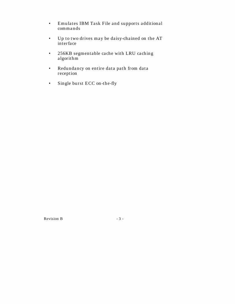
• Emulates IBM Task File and supports additionalcommands
• Up to two drives may be daisy-chained on the ATinterface
• 256KB segmentable cache with LRU cachingalgorithm
• Redundancy on entire data path from datareception
• Single burst ECC on-the-fly
- 4 - Revision B
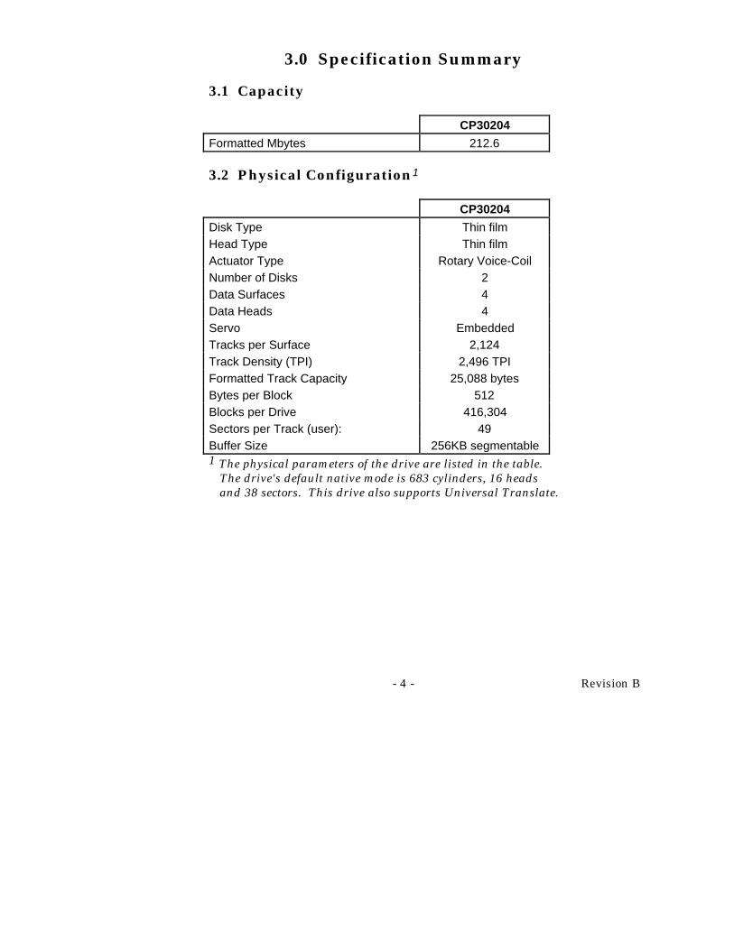
3.0 Specification Summary
3.1 Capacity
CP30204
Formatted Mbytes 212.6
3.2 Physical Configuration1
CP30204
Disk Type Thin filmHead Type Thin filmActuator Type Rotary Voice-CoilNumber of Disks 2Data Surfaces 4Data Heads 4Servo EmbeddedTracks per Surface 2,124Track Density (TPI) 2,496 TPIFormatted Track Capacity 25,088 bytesBytes per Block 512Blocks per Drive 416,304Sectors per Track (user): 49Buffer Size 256KB segmentable1 The physical parameters of the drive are listed in the table.
The drive's default native mode is 683 cylinders, 16 headsand 38 sectors. This drive also supports Universal Translate.

Revision B - 5 -
3.3 Performance
Seek Times1
Physical Track to Track 3.0 msLogical (translated) track to trackAverage
7.0 ms12.0 ms2
Maximum stroke 30.0 ms
Average Latency 6.7 msRotation Speed (+0.1%) 4498 RPMController Overhead < 500 µs
Data Transfer Rate (to/from Media) 2.5 Mbyte/secondData Transfer Rate (to/from Buffer) 8.0 Mbyte/second
Start Time(Power Up)3
(0 RPM - 4498 RPM)
(0 RPM - Ready)
typical: 10 secondsmaximum: 15 seconds
typical: 15 secondsmaximum: 20 seconds
Stop Time (Power Down) typical: 15 secondsmaximum: 20 seconds
Start/Stop cycles 20,000 minimumInterleave 1:11 The timing is measured through the interface with the drive
operating at nominal DC input voltages. The timing is basedupon the physical parameters of the disk and may be affectedby translation and/or DOS overhead at the system level.
2 The average seek time is determined by averaging the seektime for a minimum of 1000 seeks of random length over thesurface of the disk.
3 These numbers assume spin recovery is not invoked. If spinrecovery is invoked, the maximum could be 40 seconds.Briefly removing power can lead to spin recovery beinginvoked.
- 6 - Revision B
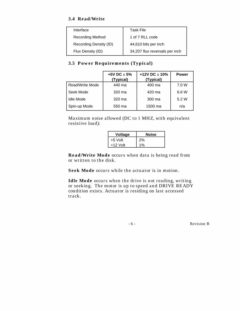
3.4 Read/Write
Interface Task File
Recording Method 1 of 7 RLL code
Recording Density (ID) 44,610 bits per inch
Flux Density (ID) 34,207 flux reversals per inch
3.5 Power Requirements (Typical)
+5V DC ± 5%(Typical)
+12V DC ± 10%(Typical)
Power
Read/Write Mode 440 ma 400 ma 7.0 W
Seek Mode 320 ma 420 ma 6.6 W
Idle Mode 320 ma 300 ma 5.2 W
Spin-up Mode 550 ma 1500 ma n/a
Maximum noise allowed (DC to 1 MHZ, with equivalentresistive load):
Voltage Noise+5 Volt 2%+12 Volt 1%
Read/Write Mode occurs when data is being read fromor written to the disk.
Seek Mode occurs while the actuator is in motion.
Idle Mode occurs when the drive is not reading, writingor seeking. The motor is up to speed and DRIVE READYcondition exists. Actuator is residing on last accessedtrack.

Revision B - 7 -
Spin-Up Mode occurs while the spindle motor isaccelerating from its rest state to its operating speed. Thespecified current is the average value over the spin-upcycle.
3.6 Physical Characteristics
Outline Dimensions ±.010" 1.00" x 4.00" x 5.75"Weight 1.3 pounds

- 8 - Revision B
4.0 Environmental Characteristics
4.1 Temperature
Operating 5°C to 55°C Non-operating -40°C to 60°C Thermal Gradient 20°C per hour maximum
4.2 Humidity
Operating 8% to 80% non-condensing
Non-operating 8% to 80% non-condensing
Maximum Wet Bulb 26°C
4.3 Altitude (relative to sea level)
Operating -200 to 10,000 feet
Non-operating (maximum) 40,000 feet
4.4 Reliability And Maintenance
MTBF 150,000 hours (POH)1
MTTR 10 minutes typical
Preventive Maintenance None
Component Design Life 5 years
Data Reliablity <1 non-recoverable error in1013 bits read
1 Projected MTBF based on comparison of similarConner products.

Revision B - 9 -
4.5 Shock and Vibration
Shock 1/2 sine pulse, 11 millisecond duration
Vibration Swept sine, 1 octave per minute
Non-operating shock 75G's
Non-operating vibration
5-62 HZ (1/2 oct/min) 0.020 inch displacement (double amplitude)
63-500 Hz (1/2 oct/min) 4 G's peak
Operating Shock 5 G's (without non-recoverable errors)
Operating Vibration 5-22 Hz .010 inch displacement (double amplitude) 23-500 Hz .5 G's (without non-recoverable error)
4.6 Magnetic Field
The disk drive will meet its specified performance whileoperating in the presence of an externally producedmagnetic field of 6 gauss DC maximum.
4.7 Acoustic Noise
The sound pressure level will not exceed 40 dBA at adistance of 1 meter from the drive.

- 10 - Revision B
4.8 Safety Standards
Conner Peripherals disk drives are designed to complywith relevant product safety standards such as:
• UL 478, 5th edition, Standard for InformationProcessing and Business Equipment andUL 1950, Safety of Information TechnologyEquipment including Electrical BusinessEquipment
• CSA 22.2 #220, Information Processing andBusiness Equipment andCSA 22.2 #950, Safety of Information TechnologyEquipment including Electrical BusinessEquipment
• TUV-IEC 380, Safety of Electrically EnergizedOffice Machines andTUV-IEC 950, Safety of Information TechnologyEquipment including Electrical BusinessEquipment
• TUV-VDE EN60950 VDE 0805/5.9
• FCC Class B Part 15 Subpart J

Revision B - 11 -
5.0 Functional Description
The drive contains all necessary mechanical andelectronic parts to interpret control signals, position therecording heads over the desired track, read and writedata, and provide a contaminant free environment for theheads and disks.
5.1 Read/Write and Control Electronics
One integrated circuit is mounted within the sealedenclosure in close proximity to the read/write heads. Itsfunction is to provide head selection, read pre-amplification, and write drive circuitry.
The dual microprocessor-controlled circuit card providesthe remaining electronic functions which include:
• Read/Write Circuitry• Rotary Actuator Control• Interface Control• Spin Speed Control• Dynamic Braking
At power down the heads are automatically retracted tothe inner diameter of the disk and are latched and parkedon a landing zone that is off of the data tracks at the innerdiameter of the disk.
5.2 Drive Mechanism
A brushless DC direct drive motor rotates the spindle.The motor/spindle assembly is dynamically balanced toprovide minimal mechanical runout to the disks. Adynamic brake is used to provide a fast stop to the spindlemotor and return the heads to the landing zone whenpower is removed.

- 12 - Revision B
5.3 Air Filtration System
The head-disk assembly is a sealed enclosure with anintegral 0.3 micron filter which maintains a cleanenvironment for the heads and disks.
5.4 Head Positioning Mechanism
The read/write heads are supported by a mechanismcoupled to a rotary voice coil actuator.
5.5 Read/Write Heads and Disks
Data is recorded on 95mm diameter disks throughminiature 3370 type thin film heads.
5.6 Customer Options
C/DUp to two drives may be daisy chained together utilizingthe 40 pin Task File connector. The maximum cablelength is 18 inches. In order to install more than onedrive, it is necessary to set a jumper option. The C/Djumper is used to determine whether the drive is a master(drive C) or slave (drive D). The drive is configured as amaster (drive C) when jumpered and as a slave drive (Ddrive) when not jumpered. (Refer to description of-PDIAG signal for further information on master/slave inConner drives.)

Revision B - 13 -
DSP & SSThis pair of jumpers determines the signals on pin 39 ofthe interface connector.
JumperDSP SS Action
X- spindle synchronization signal disabled on pin 39.- activity LED signal available on pin 39.
X- spindle synchronization signal enabled on pin 39.- activity LED signal disabled from pin 39.- pin 39 floating.
Master/slave in ATA compatible mode uses pin 39 in atime multiplexed manner to indicate that a slave drive ispresent. During power-on-reset or after RESET isasserted, this line is asserted by the slave drive within400 ms to indicate its presence. The master drive allowsup to 450 msec for the slave drive to assert -HOSTSLV/ACT. -HOST SLV/ACT is deasserted by the slavedrive following its acceptance of the first valid commandor after 31 seconds, whichever comes first.
Jumpers E1, E2, E3
E1 Jumper in disables spin-up at power-on. The drive willautomatically spin up when it receives a command which accessesthe drive.
E2 UnusedE3 Unused

- 14 - Revision B
J3 Connector
A drive select LED may be driven using two alternativepins on this drive. Pin 39 on the interface connector canbe used to drive the LED with a current limited 5 voltsupply if it is not configured for Spindle Synchronization.The 16-pin auxiliary connector (J3), pins 3 and 4 providean open collector drive signal and a current limitingresistor connected to +5V.
The spindle synchronization signal is also available onPin 2 of J3.

Revision B - 15 -
6.0 Mounting Configuration
1
2 3 4
4.00
6-32 UNC 2B 3/8" MAX (4X)
TOLERANCES: .XXX .010 + –
3.750
.125 2.375 1.750
5.75
6-32 UNC 2B 5/32" MAX (6X)
4.000
2.362
.630
.250
1.00
Figure 1. Mounting Configuration

- 16 - Revision B
7.0 Measuring Drive Specifications
7.1 Seek Times
The timing is measured through the interface with thedrive operating at nominal DC input voltages. The timingalso assumes that the BIOS and PC system hardwaredependency have been subtracted from timingrequirements and that the drive is operated using itsnative drive parameters.
Average seek time is determined by averaging the seektime for a minimum of 1000 seeks of random length overthe disk surface.
7.2 Start Time (Power Up)
Numbers specified assume that spin recovery is notinvoked. If spin recovery is invoked, the max could be 40seconds. Briefly removing power can lead to spin recoverybeing invoked.
7.3 Shock
Drives are subjected to specified G level shock for 11milliseconds with a 1/2 sine wave pulse. The drive meetsspecification without suffering non-recoverable READ orWRITE errors or other damage.
7.4 Vibration
Drives are subjected to specified vibration levels at 1/2octave per minute sweep. The drive meets thespecification without non-recoverable errors, READ orWRITE errors, or other damage.

Revision B - 17 -
J2 40 PIN
TASK FILE INTERFACE J6
POWER
1 2 3 4
1 2 3
J4 POWER
CONNECTOR
LED
HDA
C/D E1 E2 E3
SPNSYNC DSP
SPINSYNC
Figure 2. Connectors and Jumper Options

- 18 - Revision B
8.0 Electrical Description
8.1 Power Connectors
The drive has two power connectors; a standard 4 pin DCpower connector and a smaller 3 pin connector. Powermust only be supplied at one source.
The mating connector for the 4 pin connector is AMP 1-480424-0 (Housing) and AMP 60619-4 (loose piece) or61117-4 (strip) contacts.
The following table describes the 4 pin power connectorpins:
Pin Signal
1 +12V
2 GND
3 GND
4 +5V
The mating connector for the three pin connector is Molexseries 54-84 Header, housing Molex part number 39-01-0033 and terminal part number 39-00-0031 (loose) or 39-00-0023 (strip).
The following table describes the 3 pin power connectorpins.
Pin Signal
1 +5V
2 +12V
3 GND
Revision B - 19 -
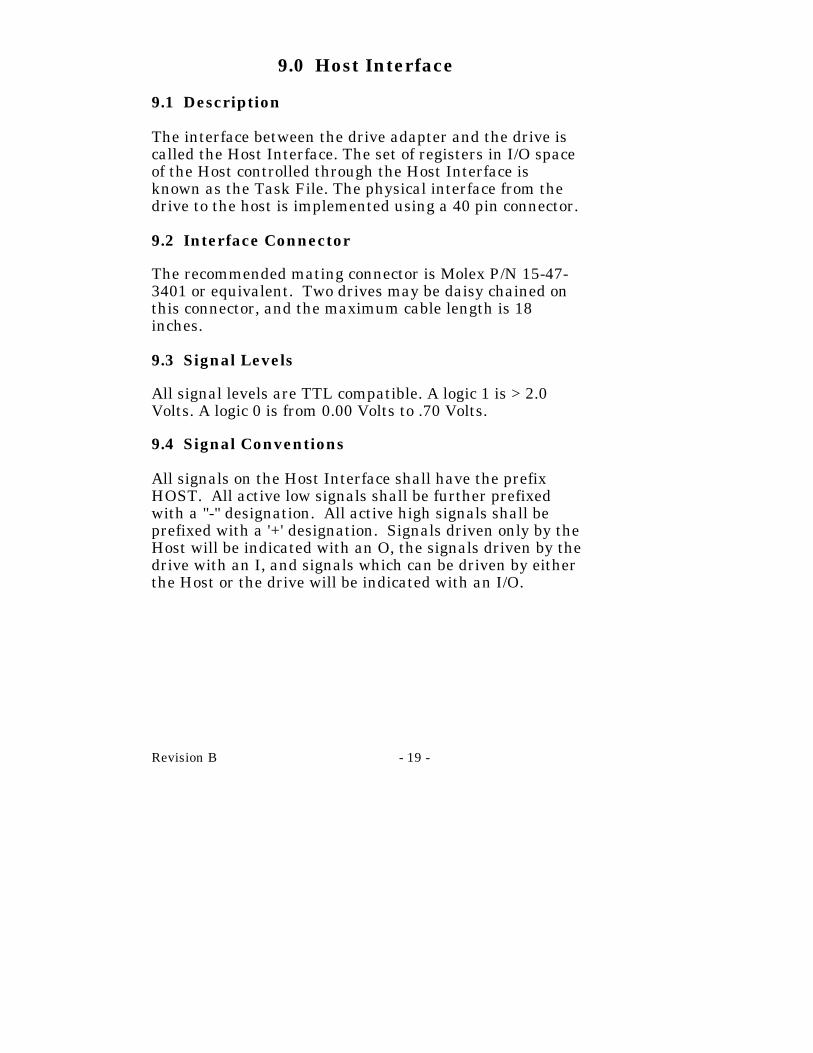
9.0 Host Interface
9.1 Description
The interface between the drive adapter and the drive iscalled the Host Interface. The set of registers in I/O spaceof the Host controlled through the Host Interface isknown as the Task File. The physical interface from thedrive to the host is implemented using a 40 pin connector.
9.2 Interface Connector
The recommended mating connector is Molex P/N 15-47-3401 or equivalent. Two drives may be daisy chained onthis connector, and the maximum cable length is 18inches.
9.3 Signal Levels
All signal levels are TTL compatible. A logic 1 is > 2.0Volts. A logic 0 is from 0.00 Volts to .70 Volts.
9.4 Signal Conventions
All signals on the Host Interface shall have the prefixHOST. All active low signals shall be further prefixedwith a "-" designation. All active high signals shall beprefixed with a '+' designation. Signals driven only by theHost will be indicated with an O, the signals driven by thedrive with an I, and signals which can be driven by eitherthe Host or the drive will be indicated with an I/O.

- 20 - Revision B
9.5 Pin Descriptions
The following table describes all of the pins on the TaskFile Interface.
Pin Signal Pin Signal
01 -HOST RESET 02 GND
03 +HOST DATA 7 04 +HOST DATA 8
05 +HOST DATA 6 06 +HOST DATA 9
07 +HOST DATA 5 08 +HOST DATA 10
09 +HOST DATA 4 10 +HOST DATA 11
11 +HOST DATA 3 12 +HOST DATA 12
13 +HOST DATA 2 14 +HOST DATA 13
15 +HOST DATA 1 16 +HOST DATA 14
17 +HOST DATA 0 18 +HOST DATA 15
19 GND 20 KEY
21 RESERVED 22 GND
23 -HOST IOW 24 GND
25 -HOST IOR 26 GND
27 RESERVED 28 +HOST ALE
29 RESERVED 30 GND
31 +HOST IRQ14 32 -HOST IO16
33 +HOST ADDR 1 34 -HOST PDIAG
35 +HOST ADDR 0 36 +HOST ADDR 2
37 -CS0 38 -CS1
39 -HOST SLV/ACT 40 GND

Revision B - 21 -
Signal Name Dir Pin Description
-HOST RESET O 1 Reset signal from the Hostsystem which is active lowduring power up and inactivethereafter.
GND O 2 Ground between the drive and the Host.
+HOST DATA I/O 3-18 16 bit bi-directional data bus 0-15 between the host and thedrive. The lower 8 bits, HD0-HD7, are used for register &ECC access. All 16 bits areused for data transfers. Theseare tri-state lines with 24 mAdrive capability.
GND O 19 Ground between the drive andthe Host.
KEY N/C 20 An unused pin clipped on thedrive and plugged on the cable.Used to guarantee correctorientation of the cable.
RESERVED O 21,27,29
GND O 22 Ground between the drive andthe host.
-HOST IOW O 23 Write strobe, the rising edge ofwhich clocks data from the hostdata bus, HD0 through HD15,into a Task File register on thedrive.
GND O 24 Ground between the drive andthe host.

- 22 - Revision B
Signal Name Dir Pin Description
-HOST READ IOR O 25 Read strobe, which when lowenables data from Task File onthe drive onto the host data bus,HD0 through HD15. The risingedge of -HOST IOR latchesdata from the drive at the host.
GND O 26 Ground between the drive andthe Host.
+HOST ALE O 28 Host Address Latch Enable. Asignal used to qualify theaddress lines. This signal ispresently not used .
GND O 30 Ground between drive and host.
+HOST IRQ14 I 31 Interrupt to the Host system,enabled only when the drive isselected, and the host activatesthe -IEN bit in the Digital Outputregister. When the -IEN bit isinactive, or the drive is notselected, this output is in a highimpedance state, regardless ofthe state of the IRQ bit. Theinterrupt is set when the IRQ bitis set by the drive CPU. IRQ isreset to zero by a Host read ofthe Status register or a write tothe Command register. Thissignal is a tri-state line with 8 madrive capacity.

Revision B - 23 -
Signal Name Dir Pin Description
-HOST IO16 I 32 Indication to the Host systemthat the 16 bit data register hasbeen addressed and that thedrive is prepared to send orreceive a 16 bit data word. Thisline is tri-state line with 24 mAdrive capacity.
-HOST PDIAG I 34 Passed diagnostic. At POR,PDIAG will be activated by theslave within 1 ms. If the masterdoesn't see -PDIAG active after4 ms it will assume no slave ispresent. -PDIAG will remainactive until the slave is ready togo not busy or 14.0 seconds ona power on reset. The masterwill wait 14.5 seconds or untilthe slave deactivates -PDIAG onpower on reset before it goesnot busy. The slave will de-activate -PDIAG and go notbusy, if it is not ready after the14.0 seconds. Neither drive willset ready or seek complete untilthey have reached full spinspeed and are ready toread/write.

- 24 - Revision B
Signal Name Dir Pin Description
During a software reset, -PDIAGwill be activated by the slavewithin 1 ms. If the masterdoesn't see -PDIAG active after4 ms it will assume no slave ispresent. The slave will not de-activate -PDIAG until it is readyto go not busy or 400 ms. Themaster will only wait 450milliseconds or until the slavedeactivates -PDIAG before wait450 milliseconds before itactivates -PDIAG and goes notbusy. The slave will not setready or seek complete untilthose states are achieved.
After reset, -PDIAG will be usedfor the diagnostic command inthe following manner. It isoutput by the drive if it is theslave drive, input to the drive if itis the master drive. This lowtrue signal indicates to a masterthat the slave has passed itsinternal diagnostic command.This line is only inactive highduring execution of thediagnostic command.
+HOST A0,A1,A2 O 3533,36 Binary coded address used to
select the individual registers inthe Task File.

Revision B - 25 -
Signal Name Dir Pin Description
-HOST CS0 O 37 Chip select decoded from thehost address bus. Used toselect some of the Hostaccessible registers. NOTE:This signal should be disabledby the Host when data transfersare in progress.
-HOST CS1 O 38 Chip select decoded from theHost address bus. Used toselect three of the registers inthe Task File.
-HOST SLV/ACT I 39 Signal from the drive used eitherto drive an activity LED or as asignal for synchronizing spindlesof a drive array, or as anindication of a second drivepresent. (See the CustomerOptions section for furtherinformation).
GND O 40 Ground between the drive andthe host.

- 26 - Revision B
9.6 Auxiliary Connector
The Auxiliary connector is used to provide optionalsignals at the front of the drive. No connection should bemade to the pins marked RESERVED. These pins arereserved for factory test purposes and improperconnection may adversely affect the drive.
Pin Signal Pin Signal
01 GND 02 Spindle Sync
03 +LED 04 -LED
05 KEY 06 KEY
07 RESERVED 08 RESERVED
09 RESERVED 10 RESERVED
11 RESERVED 12 RESERVED
13 RESERVED 14 RESERVED
15 RESERVED 16 RESERVED

Revision B - 27 -
10.0 Timing Requirements
10.1 Host Programmed I/O 8/16 Bit TimingParameters
The values in the table below refer to the timing diagramin Figure 3.
Symbol Parameter Min Max UnitsRDS IOR low to HD[0:15] 60 nsRDHLD IOR high to HD[0:15] 5 nsWDS HD[0:15] setup to IOW high 20 nsWDHLD HD[0:15] hold from IOW high 10 nsRWPULSE IOR*/IOW pulse width 75 nsADRSET HCSO, A0:2, A9/HCS1 setup 15 ns
to IOR*/IOW* lowADRHLD Address hold from IOR/IOW high 10 75 nsRWA IOR* High to IOR* Low 50 nsCS16L A0:2, HCSO setup to IOCS16* active 30 nsIOCS16HLD IO16 hold time 70 ns
A0:2
HCSO/HCSI
HD[0:15](read)
IOR/IOW
HD[0:15](write)
IOCS16
ADRSETRW PULSE
ADRHLD
RDHLDRDS
WDS
WDHLD
IOCS16HLD
RWA
Figure 3. Timing Diagram

- 28 - Revision B
10.2 Host DMA 8/16 Bit Interface Timing Parameters
The values in the table below refer to the timing diagramin Figure 4.
Symbol Parameter Min Max Unit
DREQL DREQ low from DACK low 40 nsRDS IOR low to HD[0:15] valid 60 nsRDHLD IOR high to HD[0:15] tri-state 5 nsWDS HD[0:15] setup to IOW high 20 nsRWPULSE IOR/IOW pulse width 75 nsDACKS Dack low to IOR low 0 nsDACKH Dack hold from IOR high 0 nsRWA IOR low to IOR high 50 nsBDS Between Sector Delay 270 nsWDHLD Write data Hold from IOW* High 10 ns
WDSWDHLD
RDS RDHLD
RW PULSE
DACKS
DREQL
BDS
DACKH
RWA
DREQ
DACK
IOR/IOW
HD [0:15] (READ)
HD [0:15] (WRITE)
Figure 4. Timing Diagram

Revision B - 29 -
11.0 Host Address Decoding
The Host addresses the drive using programmed I/O.This method requires that the desired register address beplaced on the three Host address lines (HA2-HA0), aproper CHIP SELECT is asserted and a READ or WRITEstrobe (-HOST IOR/-HOST IOW) is then sent to the drive.
The Host generates one of two independent chip selects onthe interface. The high order chip select, -HOST CS1, isused to access register 3F6 or 3F7. The low order chipselect, -HOST CS0, is used to address registers 1F0 - 1F7.The ECC bytes are transferred on bits 7-0.
The Host data bus 15-8 is only enabled when IO16 Enableis active and the Host is addressing the data register fortransferring data, and are only transferred if theoperation is a READ or WRITE LONG.
- 30 - Revision B
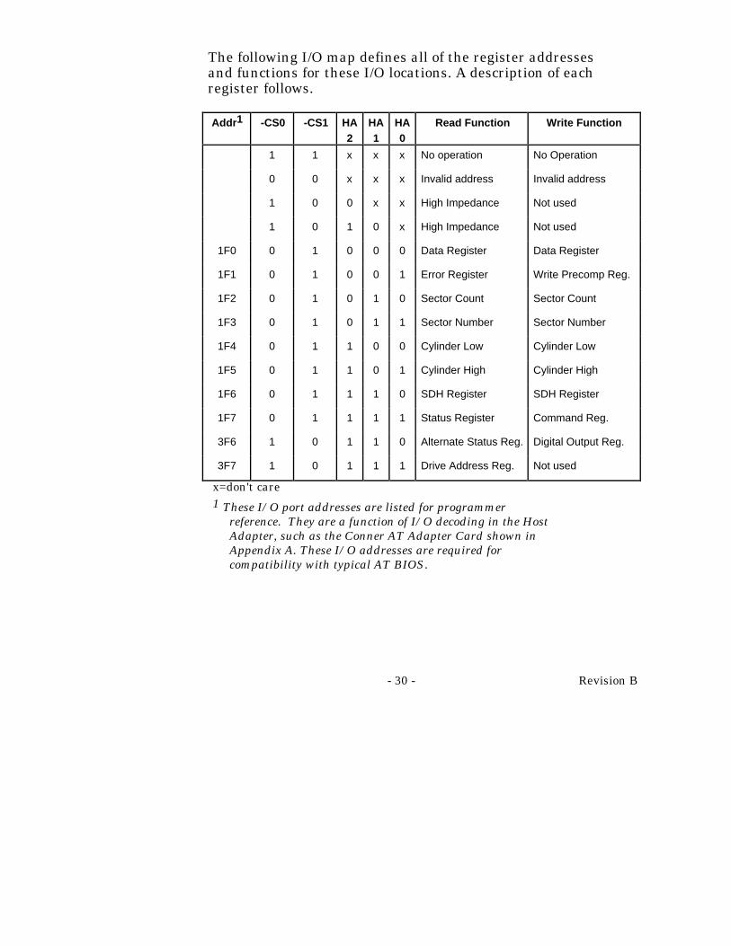
The following I/O map defines all of the register addressesand functions for these I/O locations. A description of eachregister follows.
Addr1 -CS0 -CS1 HA2
HA1
HA0
Read Function Write Function
1 1 x x x No operation No Operation
0 0 x x x Invalid address Invalid address
1 0 0 x x High Impedance Not used
1 0 1 0 x High Impedance Not used
1F0 0 1 0 0 0 Data Register Data Register
1F1 0 1 0 0 1 Error Register Write Precomp Reg.
1F2 0 1 0 1 0 Sector Count Sector Count
1F3 0 1 0 1 1 Sector Number Sector Number
1F4 0 1 1 0 0 Cylinder Low Cylinder Low
1F5 0 1 1 0 1 Cylinder High Cylinder High
1F6 0 1 1 1 0 SDH Register SDH Register
1F7 0 1 1 1 1 Status Register Command Reg.
3F6 1 0 1 1 0 Alternate Status Reg. Digital Output Reg.
3F7 1 0 1 1 1 Drive Address Reg. Not used
x=don't care1 These I/O port addresses are listed for programmer
reference. They are a function of I/O decoding in the HostAdapter, such as the Conner AT Adapter Card shown inAppendix A. These I/O addresses are required forcompatibility with typical AT BIOS.

Revision B - 31 -
11.1 Register Description
In the following register descriptions, unused write bitsshould be written with zeros and unused read bits shouldbe read as zeroes.
11.2 Data Register(-HOST CS0, address 0, R/W)
The data register is the register through which all data ispassed on READ and WRITE commands. It is also theregister to which the sector table is transferred duringFORMAT commands and the register data associatedwith the IDENTIFY command is transferred. Alltransfers are 16 bit I/O operations, except for ECC bytestransferred during R/W LONG commands. ECC transfers8 bit operations that occur after the transfer of the data.
Data is stored on the disk with the Least Significant Bytefirst, then the Most Significant Byte for each word. Thisis important to remember when testing the ECC circuitry.
- 32 - Revision B
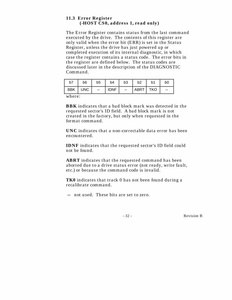
11.3 Error Register(-HOST CS0, address 1, read only)
The Error Register contains status from the last commandexecuted by the drive. The contents of this register areonly valid when the error bit (ERR) is set in the StatusRegister, unless the drive has just powered up orcompleted execution of its internal diagnostic, in whichcase the register contains a status code. The error bits inthe register are defined below. The status codes arediscussed later in the description of the DIAGNOSTICCommand.
b7 b6 b5 b4 b3 b2 b1 b0
BBK UNC -- IDNF -- ABRT TKO --
where:
BBK indicates that a bad block mark was detected in therequested sector's ID field. A bad block mark is notcreated in the factory, but only when requested in theformat command.
UNC indicates that a non-correctable data error has beenencountered.
IDNF indicates that the requested sector's ID field couldnot be found.
ABRT indicates that the requested command has beenaborted due to a drive status error (not ready, write fault,etc.) or because the command code is invalid.
TK0 indicates that track 0 has not been found during arecalibrate command.
-- not used. These bits are set to zero.
Revision B - 33 -
For other drives b0 is AMNF (Address Mark Not Found.)This is not used on Conner drives.
11.4 Write Precomp Register(-HOST CS0, address 1 write only)
This register was previously used to set writeprecompensation in non-intelligent disk drives. Thisdrive uses the Write Precomp Register for Commands EFand Fx.
11.5 Sector Count(-HOST CSO, address 2, R/W)
The Sector Count defines the number of sectors of data tobe read or written. If the value in this register is zero, acount of 256 sectors is specified. This count isdecremented as each sector is read such that the registercontains the number of sectors left to access in the eventof an error in a multi-sector operation.
In addition, the contents of this register define otherparameters in non-read/write commands as follows:
• This register is used to specify the number of sectors per track when executing an INITIALIZE DRIVE PARAMETERS command.
• This register is used in the POWER commands to provide the power down time-out parameter and status.
• This register is used to specify the number of sectorsper block in the SET MULTIPLE command.

- 34 - Revision B
11.6 Sector Number(-HOST CS0, address 3, R/W)
This register contains the starting sector number for anydisk access. At the completion of each sector, and at theend of the command this register is updated to reflect thelast sector read correctly, or the sector on which an erroroccurred. During multiple sector transfers, this register isupdated to point at the next sector to be read/written ifthe previous sector's operation was successful.

Revision B - 35 -
11.7 Cylinder Low(-HOST CS0, address 4, R/W)
The Cylinder Low Register contains the low order 8 bits ofthe starting cylinder number for any disk access. At thecompletion of each sector, and at the end of the command,this register is updated to reflect the current cylindernumber.
11.8 Cylinder High(-HOST CS0, address 5, R/W)
The Cylinder High Register contains the two high orderbits of the starting cylinder number for any disk access.At the completion of each sector, and at the end of thecommand, this register is updated to reflect the currentcylinder number.

- 36 - Revision B
11.9 SDH Register(-HOST CS0, address 6, R/W)
This register contains the drive and head numbers, asdefined below:
b7 b6 b5 b4 b3 b2 b1 b0
Don'tcare
0 Don'tcare
DRV HEAD
where:
DRV is the binary encoded drive select number. Whenthis bit is reset, the master drive is selected, and whenthis bit is set, the slave drive is selected. While the TaskFile Registers in the Master and Slave drives aresimultaneously written, this bit selects which drive willrespond to and execute the command.
HEAD is the four bit binary encoded head select number.
At the completion of each sector, and at the end of thecommand, this register is updated to reflect the currentlyselected head.

Revision B - 37 -
11.10 Status Register(-HOST CS0, address 7 read only)
This register contains the drive/controller status. Thecontents of this register are updated at the completion ofeach command. If the BSY bit is active, no other bits arevalid. The Host reading this register when an interrupt ispending is considered to be the interrupt acknowledge.Any pending interrupt is cleared when this register isread.
The bits in this register are defined below:
b7 b6 b5 b4 b3 b2 b1 b0
BSY DRDY DWF DSC DRQ CORR IDX ERR
where:
BSY is the busy bit, which is set when the drive isaccessing to the Task File registers and the Host is lockedout from accessing the Task File. This bit is set under thefollowing circumstances:
1) At activation of the HOST RESET pin in theinterface, or at activation of the software reset bitin the digital output register.
2) Immediately upon Host write of the commandregister with a Read, Read Long, Read Buffer,Seek, Recalibrate, Initialize Drive Parameters,Read Verify,Identify, or Execute Drive Diagnosticcommand.

- 38 - Revision B
3) Immediately following transfer of: A) 512 bytes ofdata after Host write of the command registerwith a Write, Format Track, or Write Buffercommand, or B) 512 bytes of data and the ECCbytes after a Host write of the Command registerwith a Write Long command. When BSY is active,any Host read of a Task File register is inhibitedand the Status register is read instead.
DRDY is the drive ready indication. When there is anerror, this bit is not changed until the Status register isread by the Host, at which time the bit again indicates thecurrent readiness of the drive. This bit will be reset atpower up and remain reset until the drive is up to speedand ready to accept a command.
DWF is the drive write fault bit. When there is an error,this bit is not changed until the Status register is read bythe Host, at which time the bit again indicates thecurrent write fault status.
DSC is the drive seek complete bit. It is an indicationthat the actuator is on track. When there is an error, thisbit is not changed until the Status register is read by theHost, at which time the bit again indicates the currentreadiness of the drive. This bit will be reset at power upand will remain reset until the drive is up to speed andready to accept a command.
DRQ is the data request bit, which indicates that thedrive is ready for transfer of a word or a byte of databetween the Host and the Data register.

Revision B - 39 -
CORR is the corrected data bit, which is set when acorrectable data error has been encountered and the datahas been corrected and on a read verify if any sector wascorrected the bit is valid. This condition will not terminateeither a MULTI-SECTOR READ or a READ MULTIPLEcommand.
IDX is the index bit which is set once per disk revolution.
ERR is the error bit, which indicates that the previouscommand ended in some type of error. The other bits inthe Status register, and the bits in the error register willhave additional information as to the cause of the error.
11.11 Alternate Status Register(-CS1, address 6, read only)
This register contains the same information as the Statusregister in the Task File. The only difference being thatreading this register does not imply interruptacknowledge to reset a pending interrupt.
b7 b6 b5 b4 b3 b2 b1 b0
BSY DRDY DWF DSC DRQ CORR IDX ERR
See the description of the Status register for definitions ofthe bits in this register.
11.12 Digital Output Register(-CS1, address 6, write only)
This register contains two control bits as follows:
b7 b6 b5 b4 b3 b2 b1 b0
-- -- -- -- -- SRST -IEN --
- 40 - Revision B
where:
-IEN is the enable bit for this disk drive interrupt to theHost. When this bit is active, and the drive is selected,the Host interrupt, +IRQ, is enabled, through a tri-statebuffer, to the Host. When this bit is inactive, or the driveis not selected the +IRQ pin will be in a high impedancestate, regardless of the presence or absence of a pendinginterrupt.
SRST is the Host software reset bit. The drive is heldreset when this bit is active, and enabled when this bit isinactive.
-- these bits are not used.
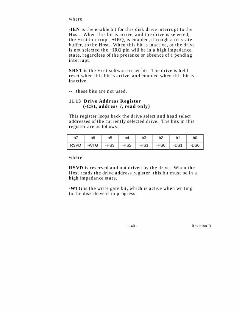
11.13 Drive Address Register(-CS1, address 7, read only)
This register loops back the drive select and head selectaddresses of the currently selected drive. The bits in thisregister are as follows:
b7 b6 b5 b4 b3 b2 b1 b0
RSVD -WTG -HS3 -HS2 -HS1 -HS0 -DS1 -DS0
where:
RSVD is reserved and not driven by the drive. When theHost reads the drive address register, this bit must be in ahigh impedance state.
-WTG is the write gate bit, which is active when writingto the disk drive is in progress.

Revision B - 41 -
-HS3 through -HS0 are the one's complement of thebinary coded address of the currently selected head. Forexample, if -HS3 through -HS0 are 1 1 0 0, respectively,head 3 is selected.
-DS1 is the drive select bit for drive 1, and should beactive when drive 1 is selected and active. -DS0 is thedrive select bit for drive 0, and should be active whendrive 0 is selected and active. It is important to note thatBit 7 is not driven for compatibility with the floppy driveaddress space. If your system is different, you may have todrive this bit when this register is read.

- 42 - Revision B
12.0 Command Description
All commands are decoded from the Command Register.The Host interface shall be programmed by the Hostcomputer to perform commands and will return status tothe Host at command completion. When two drives aredaisy chained on the interface, commands are written inparallel to both drives, only the selected drive will executethe command, except for the diagnostic command. In thatcase, both drives execute the command and the slavedrive reports its status to the master via the -HOSTPDIAG signal.
Drives are selected by the DRV bit in the drive/headRegister and by a jumper, on the drive designating it aseither a master or slave. When the DRV bit is set to 0,the master drive (C) is selected, and when the DRV bit isset to 1, the slave drive (D) is selected. When drives aredaisy chained, one must be jumpered as the master andone as the slave. When a single drive is attached to theinterface, it must be jumpered as the master. Throughoutthis document, drive selection always refers to the state ofthe DRV bit, and position of the master/slave jumper.
To issue a command, load the pertinent registers in theTask File, activate the interrupt enable bit, -IEN in theDigital Output Register, and then write the commandcode to the Command Register. Execution begins as soonas the Command Register is written.
Also see the section on retries.

Revision B - 43 -
Command Name Command Code ParametersUsed
b7 b6 b5 b4 b3 b2 b1 b0 SC SN CY SDH PR
Recalibrate 0 0 0 1 x x x x n n n d n
Read Sector(s) 0 0 1 0 0 0 L r y y y y n
Write Sector(s) 0 0 1 1 0 0 L r y y y y n
Read Verify Sector(s) 0 1 0 0 0 0 0 r y y y y n
Format Track 0 1 0 1 0 0 0 0 n n y y n
Seek 0 1 1 1 x x x x n n y y n
Execute Drive Diag. 1 0 0 1 0 0 0 0 n n n d n
Initialize Drive Parms 1 0 0 1 0 0 0 1 y n n y n
Read Multiple 1 1 0 0 0 1 0 0 y y y y n
Write Multiple 1 1 0 0 0 1 0 1 y y y y n
Set Multiple Mode 1 1 0 0 0 1 1 0 y n n d n
Power Commands 1 1 1 0 p p p p y n n d n
Read Sector Buffer 1 1 1 0 0 1 0 0 n n n d n
Write Sector Buffer 1 1 1 0 1 0 0 0 n n n d n
Identify Drive 1 1 1 0 1 1 0 0 n n n d n
Set Look Ahead 1 1 1 0 1 1 1 1 n n n d y
Translate Command 1 1 1 1 0 0 0 1 n y y y y
Physical Seek 1 1 1 1 0 0 1 0 n n y y y
Defect List 1 1 1 1 0 1 0 1 n y n d y
Enable Index 1 1 1 1 0 1 1 0 n n n d y
where:
L is the long bit, if 1, r/w long commands are executed, if0, normal r/w commands are performed.

- 44 - Revision B
r is the retry bit; 0 = retries are enabled, 1 = retries aredisabled. Retries that may be enabled/disabled are thoseon ECC and data errors. When retries are disabled at thestart of a command, they are always automaticallyenabled at the end of the command.
SC is the sector count register.
SN is the sector number register.
CY is the cylinder registers.
SDH is the drive/head register.
PR is the write precomp register.
y means the register contains a valid parameter for thiscommand. For the drive/head register, Y means that boththe drive and head parameters are used.
n means the register does not contain a valid parameterfor this command.
d means only the drive parameter is valid and not thehead parameter.
p is a valid bit for power commands EO-E3 and E5-E6.
x = don't care.

Revision B - 45 -
12.1 Recalibrate - 10
This command will move the R/W heads from anywhereon the disk to cylinder 0. Upon receipt of the command,the drive sets BSY, resets DSC, and executes a SEEK tocylinder zero. The drive then waits for the SEEK tocomplete before updating status, resetting BSY, settingDSC, and generating an interrupt. If the drive cannotreach cylinder 0, the Error Bit (ERR) is set in the StatusRegister and the track 0 (TK0) bit set in the ErrorRegister. An aborted command (ABRT) response will begiven in the Error Register if the drive is not spinning oris not on track. Upon successful completion of thecommand, the Task File Registers will be as follows:
Register Value
Error Register 00
Sector Count Unchanged
Sector Number Unchanged
Cylinder Low 00
Cylinder High 00
SDH Unchanged

- 46 - Revision B
12.2 Read Sector(s) - 2X
This command will read from 1 to 256 sectors as specifiedin the Task File (sector count equal to 0 requests 256sectors), beginning at the specified sector. As soon as theCommand Register is written, the drive sets the BSY bitand begins execution of the command.
The Error bit (ERR) is set in the Status Register and theError Register is updated; (1) if bits 2 & 3 are not equal tozero, then the Aborted Command bit (ABRT) is set, (2) ifincorrect Task File parameters are passed, the ID NotFound Error (IDNF) is set.
If the drive is not already on the desired track, an impliedSEEK is performed. Once at the desired track, the drivebegins searching for the appropriate ID field. If the ID isread correctly, the data field is read into the sector buffer,Error Bits are set if an error was encountered, the DRQbit is set and an interrupt is generated. The DRQ bit isalways set regardless of presence or absence of an errorcondition at the end of the sector. Upon commandcompletion, the Task File Registers contain the cylinder,head, and sector number of the last sector read. Thesector count is zero after successful execution of thecommand.
Multiple sector reads set DRQ and generates an interruptwhen the sector buffer is filled at the completion of eachsector, and the drive is ready for the data to betransferred to the Host. DRQ is reset and BSY is setimmediately after the Host empties the sector buffer.

Revision B - 47 -
If an error occurs during a multiple sector read, the readwill terminate at the sector where the error occurs. TheTask File Registers will contain the cylinder, head, andsector number of the sector where the error occurs. TheHost may then read the Task File to determine what errorhas occurred, and on which sector. If the error was eithera Correctable Data Error or an Non-correctable DataError, the flawed data is loaded into the sector buffer.The read does not terminate if the error was a CorrectableData Error.
If no error is detected, the cylinder, head, and sectorRegisters are updated to point to the next sequentialsector.
A read long may be executed by setting the long bit incommand code. The read long command returns the dataand the ECC bytes contained in the data field of thedesired sector. During a read long, the drive does notcheck the ECC bytes to determine there has been any typeof data Error. Data bytes are 16 bit transfers and ECCbytes are 8 bit transfers.
12.3 Write Sector(s) - 3X
This command will write from 1 to 256 sectors as specifiedin the Task File (sector count equal to 0 requests 256sectors), beginning at the specified sector. As soon as theCommand Register is written, the drive waits for the Hostto fill the sector buffer with the data to be written. Nointerrupt is generated to start the first buffer filloperation. Once the buffer is full, the drive sets BSY andbegins command execution.

- 48 - Revision B
The Error bit (ERR) is set in the Status Register and theError Register is updated, (1) if bits 2 & 3 are not equal tozero, (then the Aborted Command bit, ABRT, is set), or (2)if incorrect Task File parameters are passed, the ID NotFound Error, IDNF, is set.
If the drive is not already on the desired track, an impliedSEEK is performed. Once at the desired track, the drivebegins searching for the appropriate ID field. If the ID iscorrect, the data loaded in the buffer is written to the datafield of the sector, followed by the ECC bytes. Uponcommand completion, the Task File Registers contain thecylinder, head, and sector number of the last sectorwritten. The sector count is zero after successfulexecution of the command.
Multiple sector writes set DRQ and generate an interrupteach time the buffer is ready to be filled. DRQ is resetand BSY is set immediately when the Host fills the sectorbuffer. If an Error occurs during a multiple sector write,it will terminate at the sector where the error occurs. TheTask File indicates the location of the sector where theerror occurred. The Host may then read the Task File todetermine what error has occurred, and on which sector.If no error is detected, the cylinder, head, and sectorRegisters are updated to point at the next sequentialsector.
A write long may be executed by setting the long bit in thecommand code. The write long command writes the dataand the ECC bytes directly from the sector buffer; thedrive will not generate the ECC bytes itself for the writelong command. Data byte transfers are 16 bits, ECCbytes are 8 bit transfers.
Revision B - 49 -
12.4 Verify Sectors - 4X
This command functions similarly to the READSECTORS command except that no data is transferred tothe host and at completion of the command the CORR bitis set if software ECC correction was required. The driveremains BUSY until all data is verified. If LOOKAHEAD's are active, the VERIFY command will also workthe same as when a READ is performed.
12.5 Format Track - 5X
The purpose of the FORMAT TRACK command is toprovide a means by which a defective sector may either bemarked bad or reassigned. This command has been usedon other drives to do the low level formatting job ofputting the header and creating the data fields for alltracks on the drive. It is not necessary to execute aFORMAT command prior to operating the drive on theHost PC because the drive is a hard sectored drive and allrequired low level formatting is done during the factorycertification of the drive. Conner supports the FORMATcommand only to allow any sectors that become defectiveto be handled in a fashion required by different operatingsystems. The FORMAT command operates on one singlelogical track at a time and all sectors on that track arefilled with zeroes.
As indicated above, there are two methods provided tohandle defective sectors. When a sector is marked bad,the ID field of the sector is updated to indicate a badblock. Any time that sector is accessed thereafter, thedrive will return bad block status in the Error Register.The second method, Assign, allows a spare sector on thedrive to be used to replace the specified sector. Followingthis operation, the drive performance will be degradedslightly when the sector is accessed due to the driveautomatically going to the new sector.

- 50 - Revision B
It is also possible to format a bad block good and unassignan alternate. When a sector is un-assigned, the sparesector that was used as the alternate can be reclaimed.However, since the assigned sector could be an alternateitself it is not correct to write a diagnostic that assignsand then unassigns alternates on a large scale, becausethe spare sectors will be lost.
The command is similar to a write command, where theTask File parameters are written, the Command Registeris written to begin the command, and the drive respondsby activating DRQ in the Status Register. This indicatesa request for 1 sector (512 bytes) of data that is used todescribe the operations to be performed on each sector ofthe track specified by the Task File. After the data iswritten to the Data Register, the drive analyzes theinformation for each sector and performs the requestedaction to each sector. When the command is complete, thedrive raises Interrupt Request with ending status in theTask File.
The data in the sector buffer must conform to a specifiedformat. There must be one word, 2 bytes, for each sector.The words must be contiguous and begin at the start ofthe sector. Unlike some drives where the order of thewords is used to determine the interleave, the order of thewords is not significant because the drive's interleavecannot be changed. The most significant byte of eachword must contain the sector number. The leastsignificant byte must contain a descriptor byte thatindicates what is to be done to each sector. There are fourpossible descriptor bytes:
1. 00H = format sector good2. 80H = format sector bad3. 40H = assign this sector to an alternate location

Revision B - 51 -
4. 20H = unassign the alternate location for this sector
The drive will return an ID not found under the followingconditions:
1. If there is a missing word for any sector along thetrack.
2. If the words are not contiguous from the start of the sector.
3. If there is more than one (1) word per sector.4. If the Task File calls for an illegal cylinder and/or
head Register.
A utility program to handle defective sectors shouldprovide some interface to identify defective sectors. Theprogram should build a 512 byte block with a word foreach sector for the track containing the defective sector.The most significant byte of each word should contain thesector number. The defective sectors descriptor byteshould be set to either 80H or 40H depending on whetheror not the sector is to be formatted bad or reassigned. Allof the remaining sectors should have a descriptor byte of00H. Once the data block is created, the FORMATcommand can be executed.
It is important to remember that all data on the track islost. The drive formats logical track as defined by thepower-on-reset default, or by the values issued by the lastINITIALIZE DRIVE PARAMETERS command.

- 52 - Revision B
12.6 Seek - 7X
This command selects the head specified in the Task Fileand initiates a SEEK to the desired track. When thecommand is issued, the drive sets BSY in the StatusRegister, resets SEEK COMPLETE (DSC), initiates theSEEK, resets BSY, and generates an interrupt. Only theCylinder Register and Drive Head Register are valid forthis command.
The drive does not wait for the SEEK to complete beforereturning the interrupt. SEEK COMPLETE (DSC) willbe set upon completion of the command. If a newcommand is issued to a drive while a SEEK is beingexecuted, the drive will wait, with BSY active, for theSEEK to complete before executing the new command. Nochecks are made on the validity of the Sector number inthe Task File. The Error Bit (ERR) in the Status Registerand the ID Not Found (IDNF) bit in the Error Register ofthe Task File will be set if an illegal cylinder number ispassed.

Revision B - 53 -
12.7 Execute Drive Diagnostic - 90
This command performs the internal diagnostic testsimplemented by the drive. The diagnostic tests are onlyexecuted upon receipt of this command. The drive setsBSY immediately upon receipt of the command. If thedrive is a master, the drive performs the diagnostic testsand saves the results. It then checks to see if a slave driveis present and waits up to 5 seconds for the slave tocomplete its diagnostics. If the slave successfullycompletes its diagnostics, it asserts -HOST PDIAG. Ifunsuccessful, the master drive resets BSY in the StatusRegister, and generates an interrupt. The Error bit (ERR)is set in the Status Register and the Error Register isupdated.
The value in the Error Register should be viewed as aunique 8 bit code and not as the single bit flags definedpreviously. The interface Registers are set to initialvalues except for the Error Register.
- 54 - Revision B
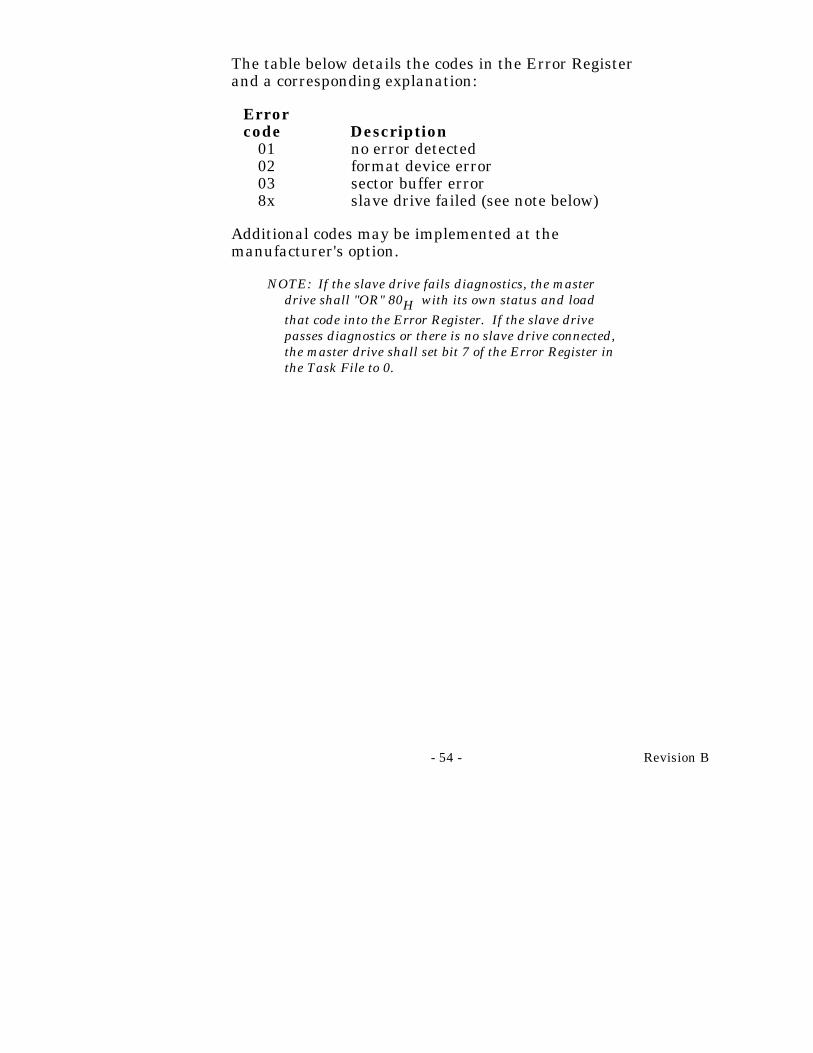
The table below details the codes in the Error Registerand a corresponding explanation:
Errorcode Description
01 no error detected02 format device error03 sector buffer error8x slave drive failed (see note below)
Additional codes may be implemented at themanufacturer's option.
NOTE: If the slave drive fails diagnostics, the masterdrive shall "OR" 80H with its own status and loadthat code into the Error Register. If the slave drivepasses diagnostics or there is no slave drive connected,the master drive shall set bit 7 of the Error Register inthe Task File to 0.
Revision B - 55 -
12.8 Initialize Drive Parameters - 91
This command enables the host to set the head switch andcylinder increment points for multiple sector operations.The sector count and SDH registers are used to specifythe logical sectors per track and number of heads for thedrive. The cylinder count is calculated by the drive basedon these two parameters. In the TRANSLATE mode, thelogical head and sector numbers in the Task File will betranslated to their native physical values as part ofexecution of the command. The sector and head, values inthe Task File are not checked for validity by thiscommand. Upon receipt of this command, the drive setsBSY, saves the parameters, resets BSY, and generates aninterrupt.
The UNIVERSAL TRANSLATE MODE enables the userto configure the drive to any cylinder, head, and sectorconfiguration desired. The translate configuration islimited only by the maximum capacity of the drive. Uponinitial power up of the drive it will default to apredetermined configuration detailed in the specificationsummary of this manual.
After the drive is ready, the host system may issue INITDRIVE PARMS COMMAND to alter the translateconfiguration (number of heads and number of sectors pertrack). The drive parameters will then be saved inEEPROM for subsequent drive operations.

- 56 - Revision B
12.9 Read Multiple Command - C4
The READ MULTIPLE command is identical to theREAD SECTORS operation except several sectors aretransferred to the Host as a block without interveninginterrupts. In addition the DRQ qualification of thetransfer is required only on the first sector of the block ofsectors to be transferred. Long transfers are notpermitted. The block count, which is the number ofsectors to be transferred as block, is programmed by theSET MULTIPLE mode command which must be executedprior to the READ MULTIPLE command. When theREAD MULTIPLE command is issued, the Sector CountRegister will contain the number of sectors (not thenumber of blocks or the block count) requested.
If this sector count is not evenly divisible by the blockcount, as many full blocks as possible are transferred,followed by a final, partial block transfer. The partialblock transfer will be for N sectors, where
N = (sector count) modulo (block count).
If the multiple command is attempted before the SETMULTIPLE mode command has been executed or whenmultiple commands are disabled, the multiple operationwill be rejected with an Aborted Command Error.

Revision B - 57 -
Disk errors encountered during multiple commands willbe reported at the beginning of the block or partial blocktransfer, but DRQ will still be set and the transfer willtake place as it normally would, including transfer ofcorrupt data, if any. Subsequent blocks or partial blockswill only be transferred if the error was a correctable dataerror. All other errors will cause the command to stopafter transfer of the block which contained the error.Interrupts are generated when DRQ is set at thebeginning of each block or partial block.
12.10 Write Multiple Command - C5
The WRITE MULTIPLE command performs similarly tothe WRITE SECTORS command except that thecontroller sets BSY immediately upon receipt of thecommand, data transfers are multiple sector blocks, andthe long bit is not valid. Several sectors are transferredto the Host as a block without intervening interrupts, onlyrequiring DRQ qualification of the transfer at the start ofthe block, not on each sector. There is no IRQ prior to thefirst block transfer. The block count, which is the numberof sectors to be transferred as block, is programmed by theSET MULTIPLE mode command, which must be executedprior to the WRITE MULTIPLE command. When theWRITE MULTIPLE command is issued, the Sector CountRegister will contain the number of sectors (not thenumber of blocks or the block count) requested. If thissector count is not evenly divisible by the block count, asmany full blocks as possible are transferred, followed by afinal, partial block transfer. The partial block transfer willbe for N sectors, where N = (sector count) modulo (blockcount). If the WRITE MULTIPLE command is attemptedbefore the SET MULTIPLE mode command has beenexecuted or when WRITE MULTIPLE commands aredisabled, the WRITE MULTIPLE operation will berejected with an Aborted Command Error.
- 58 - Revision B
All disk errors encountered during WRITE MULTIPLEcommands will be reported after the attempted disk writeof the block or partial block is transferred. The writeoperation will end with the sector in error, even if it wasin the middle of a block. Subsequent blocks will not betransferred in the event of an error. Interrupts aregenerated when DRQ is set at the beginning of each blockor partial block.
12.11 Set Multiple Mode - C6
This command enables the controller to perform READMULTIPLE and WRITE MULTIPLE operations andestablishes the block count for these commands. Prior tocommand issuance, the Sector Count Register should beloaded with the number of sectors per block. Block countssupported are multiples of 2 up to the buffer size of eachdrive, e.g. 1,2,4,8. . . .
Upon receipt of the command, the controller sets BSY andlooks at the Sector Count Register contents. If theregister contents are valid and a supported block count issupplied, that value is loaded for all subsequent READMULTIPLE and WRITE MULTIPLE commands andexecution of these commands is enabled. Anyunsupported block count in the register will result in anAborted Command Error and READ MULTIPLE andWRITE MULTIPLE commands being disabled. If theSector Count Register contains 0 when the command isissued, READ MULTIPLE and WRITE MULTIPLEcommands will be disabled. Once the appropriate actionhas been taken, the controller resets BSY and generatesan interrupt. At power up default is READ MULTIPLEand WRITE MULTIPLE are disabled. The state of READMULTIPLE and WRITE MULTIPLE is maintainedthrough both hardware and software resets.

Revision B - 59 -
12.12 Power Commands - EX
Commands EO through E3 and E5-E6 constitute thePOWER commands. The following table describes thesecommands:
Command Drive Action
EO The drive enters STANDBY MODE immediately.
E1 The drive enters IDLE MODE immediately.
E2 The drive enters STANDBY MODE immediately. If the Sector Count registeris non-zero then the Auto Power-Down feature is enabled and will take effect when the drive returns to IDLE MODE. If the Sector Count register is zero then the Auto Power-Down feature is disabled.
E3 The drive enters the IDLE MODE immediately. If Sector Count register is non-zero then the Auto Power-Down feature is enabled and will take effect immediately. If the Sector Count register is zero, then the Auto Power-Down feature is disabled.
E5 Puts FFH in Sector Count register if driveis in the IDLE MODE. Puts 00H in Sector Count register if drive is in, going to, or recovering from the STANDBY MODE. Puts a BBH in the sector count register if power lock is enabled.

- 60 - Revision B
E6 The drive enters the SLEEP MODE. A reset is required to bring the drive out of sleep mode.
Note: Minimum power off/on cycle time should be no lessthan 3 seconds.
All of the POWER commands except command E6 willexecute immediately and return the ending interruptafter the spin up/down sequence is initiated. Please notethat if the drive is already spinning (IDLE MODE) and aspin up command is issued from the host, the spin upsequence is not initiated.
Similarly, if the drive is in the STANDBY MODE and thehost issues a spin down command, the spin downsequence is not initiated. Return of the ending interruptdoes not mean that the drive has fully transitioned to thedesired operating mode. The SLEEP command is theexception. In command E6, the drive is spun down andwhen it is stopped, the drive returns the ending interruptand the SLEEP MODE begins.
When enabling the Auto Power-down feature, the value inthe Sector Count Register specifies the number of 5second increments for the time-out value. If the drivedoes not receive a command within the specified time, thedrive will enter the STANDBY MODE. The minimumtime-out value is 60 seconds which means the smallestvalue for the Sector Count Register is 12 when enablingthe Auto Power-down feature. If a number between 1 and11 inclusive is specified in the Sector Count Register, avalue of 12 is used. This prevents overheating of the driveduring spin up/down sequences.

Revision B - 61 -
The maximum allowable time-out value is 1000 seconds,or 16.6 minutes, resulting in a maximum Sector CountRegister value of 200. If a number greater than 200 isspecified, a value of 200 is used.
Assertion of Host Reset will only affect the current stateof the SLEEP MODE. If the drive is in SLEEP MODEand Host Reset is asserted, the drive wakes up intoSTANDBY MODE. Please note that the drive will notreturn to the state it was in when the host issued thesleep command. The default power-on condition of thedrive is IDLE MODE.

- 62 - Revision B
12.13 Read Buffer - E4
The READ BUFFER command allows the Host to readthe current contents of the drive's sector buffer. Only theCommand Register is valid for this command. When thiscommand is issued, the drive will set BSY, set up thesector buffer for a operation, set DRQ, reset BSY, andgenerate an interrupt. The Host may then read up to 512bytes of data from the buffer. If 599AH is placed in theCylinder Register then the Sector Count Register is usedto pass that many sectors out of the buffer. If therequested sector count is larger than the buffer anAborted Command error status is returned.
12.14 Write Buffer - E8
The WRITE BUFFER command allows the Host tooverwrite the contents of the drive's sector buffer with anydata pattern desired. Only the Command Register isvalid for this command. When this command is issued, thedrive will set BSY, set up the sector buffer for a writeoperation set DRQ, reset BSY. The Host may then writeup to 512 bytes of data to the buffer. If 599AH is placedin the Cylinder Register the Sector Count Register is usedto determine how many sectors will be written. If theSector Count is larger than the buffer an AbortedCommand error status is returned.

Revision B - 63 -
12.15 Identify Drive - EC
The IDENTIFY command allows the Host to receiveparameter information from the drive. When thecommand is issued, the drive sets BSY, stores therequired parameter information in the sector buffer, setsthe DRQ bit, and generates an interrupt. The Host maythen read the information out of the sector buffer. Theparameter words in the buffer are arranged as follows, allreserved bits or words should be zeroes. All numbers aregiven in hexadecimal format right justified. All reservedwords are zero.
Word 00 A constant 0C5AWord 01 Default logical cyl.Word 02 Number of removable cyl.Word 03 Default logical headWord 04 Number of unformatted bytes/physical trackWord 05 Number of unformatted bytes/sectorWord 06 Default logical sectorWord 07 Number of bytes in the inter-sector gapsWord 08 Number of bytes in the sync fieldsWord 09 0000Word 10-19 Serial numberWord 20 Controller type 0003 dual ported multiple
sector buffer with LOOK AHEAD's.Word 21 Controller buffer size in 512 byte incrementsWord 22 Number of ECC bytes passed on read/write
long commandsWord 23-26 Controller firmware revisionWord 27-46 Model numberWord 47 Number of sectors/interruptWord 48 Double word transfer flag (0 = not capable, 1
= capable)Word 49 Assign Alternate (0 = not capable, 1 =
capable, See Format Description)Word 50 Modes supported (7 - XT & AT supported)

- 64 - Revision B
Word 51 Features supportedWord 52-127 ReservedWord 128 Native number of cylindersWord 129 Native number of heads, sectorsWord 130 Current logical number of cylindersWord 131 Current logical number of heads, sectorsWord 132 Interface flag, Drive Feature bytes.
bit F Reservedbit E Reservedbit D Reservedbit C Reservedbit B Reservedbit A Reservedbit 9 Reservedbit 8 ATA master/slave enablebit 7 Enable spindle syncbit 6 Reservedbit 5 Inhibit spin on power upbit 4 Reservedbit 3 Disable lookahead read controlbit 2 Reservedbit 1bit 0 C flag
Word 133 Power feature not supportedWord 134 Identify command flag
bit 15thru 2 Undefinedbit 1 Cam compliantbit 0 Physical parameter pointer
0 Physical in words 1,3,61 Physical in words 128, 129
Word 135 Drive AgeWord 136-255 Reserved

Revision B - 65 -
12.16 Set Look Ahead Read - EF
This command provides capability to enable or disable theLOOK AHEAD capability. "AAH" in the Write PrecompRegister enables LOOK AHEADs. The default state onpower up or reset is LOOK AHEAD enabled. "55H"disables LOOK AHEADs. Any other values in the WritePrecomp Register will result in an Aborted CommandError.
12.17 Translate Command - F1
The command uses parameters passed to the drive in theCylinder High, Cylinder Low, SDH and Sector NumberRegisters. These values are then translated into thephysical location on the drive and values are passed backthrough their respective registers and a interrupt is sent.An AAH must be loaded in the write precomp Register oran Aborted Command error will result.

- 66 - Revision B
12.18 Physical Seek - F2
The command uses parameters passed to the drive in theCylinder High, Cylinder Low, and SDH Registers. Theparameters are checked for validity and if correct a SEEKis performed to that physical location on the drive. Aninterrupt will be sent at the start of the SEEK and busycleared. When the SEEK is complete the SEEKCOMPLETE (DSC) bit in the Status Register will be set.Valid cylinder parameters will be 5 to max cylinder (fromID command word 128) if the Sector Count Registercontains any value other than FFH. If the Sector CountRegister contains FFH then an offset of 8 will be added tothe value in the Cylinder registers. Valid head parameterwill be from 0 to max head - 1 (from ID command, word129, most significant byte). An AAH must be loaded inthe Precomp Register or an Aborted Command error willresult.
Revision B - 67 -
12.19 Defect List - F5
The command returns three Factory Defect Lists in 6blocks, the first 4 blocks being the skip list and the last 2blocks being the alternate list. The drive will set theSector Count Register to 6 at the start of the commandand is the only Register altered as the data is read.Defect information is returned with a 4 byte headerfollowed by 7 byte defect descriptors. The format of theData is as follows:
Byte 0 - error log #Byte 1 - error log type 0 or 2Byte 2,3 - reserved
Seven byte defect descriptors follow in the followingformat:
Byte 0 - Error CodeByte 1 - Cylinder HighByte 2 - Cylinder LowByte 3 - HeadByte 4 - SectorByte 5 - SenseByte 6 - Count

- 68 - Revision B
Each of the logs are 2 blocks long. The error logs will be2AH and 2BH for skip logs and 2CH for alternate logs.The error code is 50H for the skip list and 51H for thealternate list. An AAH must be loaded in the PrecompRegister or an Aborted Command error will result.
If the precomp Register is loaded with a BBH then a scanID will be performed. The drive will take the physical,not logical, parameters from the Cylinder High, CylinderLow and drive head Registers and scan that track's ID foralternates. The results will be returned in two 512 byteblocks in the same format as used for the factory defectlist.

Revision B - 69 -
12.20 Enable Index - F6
This command enables an index pulse to be generated bythe drive. This pulse is located physically in the samespot across the entire disk. This command will degradeperformance of the drive so it should only be used fordiagnostic purposes. An AAH must be loaded in thePrecomp Register or an Aborted Command error willresult.

- 70 - Revision B
13.0 Error Reporting
In general, errors are detected in the following fashion bythe drive microprocessor. At the start of the execution ofthe command, the command register is checked forconditions that would lead to an aborted command. Thenthe operation is attempted. The errors that are valid foreach command are summarized below. Any subsequenterror terminates the command at the point that it isdiscovered.
Command Error Type Valid
Recalibrate ABRT, TKO, DRDY, DWF, DSC, ERR
Read Sector(s) BBK, UNC, IDNF, ABRT, DRDY, DWF, DSC, CORR, ERR
Read Long BBK, IDNF, ABRT, DRDY, DWF, DSC, ERR
Write Sector(s) BBK, IDNF, ABRT, DRDY, DWF, DSC, ERR
Write Long BBK, IDNF, ABRT, DRDY, DWF, DSC, ERR
Verify Sectors BBK, UNC, IDNF, ABRT, DRDY, DWF, DSC, CORR, ERR
Format Track IDNF, ABRT, DRDY, DWF, DSC, ERR
Seek IDNF, ABRT, DRDY, DWF, DSC, ERR
Execute Drive Diag. ABRT, ERR1
Init Driv Parm ABRT, ERR

Revision B - 71 -
Read Multiple BBK, UNC, IDNF, ABRT, DRDY, DWF, DSC, CORR, ERR
Write Multiple BBK, IDNF, ABRT, DRDY, DWF, DSC, ERR
Set Multiple ABRT, ERR
Read Buffer ABRT, ERR
Write Buffer ABRT, ERR
Identify Drive ABRT, ERR
Set Look Ahead Read ABRT, ERR
Translate Command ABRT, ERR
Physical Seek ABRT, ERR
Defect List ABRT, ERR
Invalid Command Code ABRT, ERR
1See Command Description for error byte decoding.

- 72 - Revision B
14.0 Miscellaneous Topics
The following paragraphs describe operations that spanseveral commands or are not covered sufficiently in thepreceding paragraphs.
14.1 Reset
A RESET condition will set the DRIVE BUSY, allowingthe drive to perform the proper initialization required fornormal operation. A RESET condition can be generated inthree ways. There are two hardware resets, one from theHost (- HOST RESET) and one from the drive powersense circuitry. These are set 'high' when the system andthe drive respectively acknowledge stable power. Theother reset is software generated. The Host can write tothe Digital Output Register and set the -HOST RESETbit. The Host SOFTWARE RESET condition will persistuntil the RESET Bit is set to a zero.
Once the RESET has been removed and the drive hasbeen re-enabled, with BSY still active, the drive willperform any necessary hardware initialization, clear anypreviously programmed drive parameters, revert to thedefaults, load the Task File Registers with their initialvalues, and then reset BSY. No interrupt is generatedwhen initialization is complete. The initial values (hex)for the Task File Registers are as follows:
Error Register 01Sector Count 01Sector Number 01Cylinder Low 00Cylinder High 00Drive/Head 00

Revision B - 73 -
The drive disables the cache and reallocates the cache tothe default number of segments.
14.2 Reset Timing
There are two reset conditions: 1) When power is appliedand 2) When a SOFTWARE or HARDWARE RESET isreceived from the host.
When the power is applied to the drive, it performsinitialization, executes a ROM test, a buffer memory test,an internal and external RAM test, and then the drivebegins spinning up. While the drive is spinning up, theinterface is initialized. After going through initialization,the drive waits for the spin up process to complete beforesetting READY and SEEK COMPLETE in the StatusRegister and going NOT BUSY. If the drive haspreviously been commanded to spin down or if it has spundown due to a power command timeout, the drive will notwait for spin up to complete before going NOT BUSY withREADY and SEEK COMPLETE set in the StatusRegister. If the drive times out waiting for spin up tocomplete, it will go NOT BUSY without setting READYand SEEK COMPLETE. When and if the drive completesspin up after timing out, READY and SEEK COMPLETEwill be set. The internal timeout for the drive goingREADY is approximately 10 seconds.
When a Host HARDWARE or SOFTWARE RESET isreceived, only the interface initialization process isexecuted as previously described.
NOT BUSY. If just a Host HARDWARE or SOFTWARERESET takes place and the drive is spinning, the resetwill only take about 4-6 milliseconds to achieve READY,SEEK COMPLETE and NOT BUSY.
- 74 - Revision B
14.3 Busy Condition
The status bit for BUSY is set in a number of ways. ARESET condition described previously is one way.Another method occurs when the Host issues a commandby writing to the command register. The status register isclocked BUSY on the Host write of the CommandRegister, for any command except a WRITE, FORMAT orWRITE LONG command. The disk controller andmicroprocessor prepare the data to return to the host andset the drive NOT BUSY to allow the Host access of thedata requested.
On a write type command, the command is issued, settingDATA REQUEST but BUSY is not set until the data to bewritten is put into the RAM buffer. Write typecommands include WRITE SECTOR(s), FORMAT,WRITE SECTOR BUFFER and WRITE LONG.
In addition, the drive microprocessor has the ability toset/reset BUSY. This is the only method that BUSY canbe cleared. This means that the only way a drive canrespond properly to a command is for the drivemicroprocessor to be active. When BUSY is active, thedrive has read and write access to the Task File Registersand the Host can only read the Status Register andAlternate Status Register of the Task File. Anyattempted Host read of a Task File Register while BSY isactive, results in reading the Status Register.
When BUSY is inactive, the Host has read and writeaccess to all Task File Registers.

Revision B - 75 -
14.4 Conner Master/Slave
The drive is equipped with a -C/D jumper. To select thedrive as the master, in a two drive or ported system, or asingle drive, the -C/D jumper should be installed. If thejumper is not installed, the drive will configure as theslave. The -PDIAG line is used as the slave present signalto the master in the following way.
At power on time -PDIAG will be activated by the slavewithin 1 ms. If the master does not see -PDIAG activeafter 4 ms it will assume no slave is present. -PDIAG willremain active until the slave is ready to go not busy or14.0 seconds after a Power On Reset. The master willwait 14.5 seconds or until the slave deactivates -PDIAGon Power On Reset before it goes not busy. The slave willdeactivate -PDIAG and go not busy, if it is not ready afterthe 14.0 seconds. Neither drive will set Ready or SeekComplete until they have reached full spin speed and areready to read and write.
During a software reset, -PDIAG will be activated by theslave within 1 millisecond. If the master does not see-PDIAG active after 4 ms it will assume that no slave ispresent. The slave will not deactivate -PDIAG until it isready to go not busy or 400 ms. The master will only wait450 ms or until the slave deactivates -PDIAG before itgoes not busy. The slave will only wait 450 ms before itactivates -PDIAG and goes not busy. The drive will notset Ready or Seek Complete until those states areachieved.
After Reset, -PDIAG is used in its normal diagnosticfunction during the diagnostic command.

- 76 - Revision B
14.5 Error Detection and Correction (EDAC)
The drive uses a Reed-Solomon code to perform errordetection and correction. The polynomial is able to detecta single burst of up to 51 bits in length or up to threebursts each of which may be up to 11 bits in length.
The error correction capability of the polynomial is asingle error burst with a maximum length of 22 bits ortwo independent error bursts of up to 11 bits each per 512byte block. A single burst of 11 bits or less is corrected"on-the-fly" with no performance degradation. The mis-correction probability using this "on-the-fly" errorcorrection is superior to the detection capability of thetraditionally used 56 bit computer generated code.