Connell Wagner Pty Ltd Adelaide - Modular Precast · It is a condition for the use of these design...
46
CNS Connell Wagner Pty Ltd ABN 54 005 139 873 124 Weymouth Street Adelaide South Australia 5000 Australia Telephone +61 8 8231 4766 Facsimile +61 8 8231 4765 [email protected] www.conwag.com Engineering calculations for Precast Concrete Modules for Constress Modular Systems. November 2003 Reference: E433.00
Transcript of Connell Wagner Pty Ltd Adelaide - Modular Precast · It is a condition for the use of these design...

CNS
Connell Wagner Pty LtdABN 54 005 139 873124 Weymouth StreetAdelaideSouth Australia 5000 Australia
Telephone +61 8 8231 4766Facsimile +61 8 8231 4765
Engineering calculations for PrecastConcrete Modules for ConstressModular Systems.
November 2003Reference: E433.00

n Connell WagnerStructural Calculations
Contentsnn Project: : tics1,01..e..s ( 3 ,..s---.i.„ .. ,.,--1 cazaz.re . Project/Job No.: "-.E 433. CO
Client/Architect: cot4ster jAct,otAs s-/ srFJN_ Date: 44y 2c,c,1403:2_
Designers : —E:41.c_
Project component : z-ro_oc.mnA.L.— ---v.8 St C. t'•Sources Design of Information (input)---a tep., Lerrau,n,ne. C t ..r.? t-ic•-u•).-3-->S510J
Class of Building:
Codes and Standards Used (Tick Those Applicable)
s/ AS 1170.1 SAA Loading Code - Dead and Live
Z AS 1170.2 SAA Loading Code - Wind Loads
‘/. AS 1170.4 SAA Loading Code - Earthquake Loads
AS 1554 SAA Structural Steel Welding Code
AS 1684 SAA Timber Framing Code
AS 1720 SAA Timber Engineering Code
AS 2870 Residential Slabs and Footings
7 AS 3600 SAA Concrete Structures Code
AS 3610 SAA Formwork for Concrete
AS 3700 SAA Masonry Code
AS 3990 SAA Mechanical Equipment Steelwork
AS 4100 SAA Steel Structures Code
Building Code of Australia
Other (specify):
Contents (for larger projects, refer to index attached) Page No's
Principles/Design Philosphy/Preamble 1Design Loads 112
-9111....K.A-041..M.— Th----p_sv...r. 3-2, 2 5--
Ths>41.A.-31.40.S 51 -4 S
Others (specify)
FILE DOCUMENT1 17 May 2001 I PAGE 1 of 2
Date: 23 Ito ic,_&
Connell Wagner
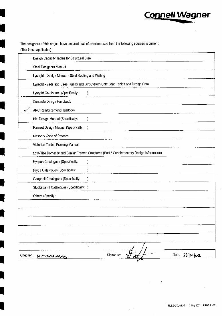
The designers of this project have ensured that information used from the following sources is current:
(Tick those applicable)
Design Capacity Tables for Structural Steel
Steel Designers Manual
Lysaght - Design Manual - Steel Roofing and Walling
Lysaght - Zeds and Cees Purlins and Girt System Safe Load Tables and Design Data
Lysaght Catalogues (Specifically:
Concrete Design Handbook
ARC Reinforcement Handbook
Hilti Design Manual (Specifically:
Ramset Design Manual (Specifically: )
Masonry Code of Practice
Victorian Timber Framing Manual
Low-Rise Domestic and Similar Framed Structures (Part 5 Supplementary Design Information)
Hyspan Catalogues (Specifically:
Pryda Catalogues (Specifically:
Gangnail Catalogues (Specifically: )
Stockspan II Catalogues (Specifically: )
Others (Specify):
...)
)
)
Checker: v4 .--TswaitAftts Signature:
FILE DOCUMENT1 I 7 May 2001 I PAGE 2 of 2

nnnnnnnnnnn
nnnnn
nn
Connell Wagner
Structural Notes on Calculations
1. General
These calculations are to be read in conjunction with any Architectural, Structural and other associated drawings.
The design is for only those items for which specific calculations are carried out and for those elements detailed on the structural drawings.The performance of other elements whether structural members or not, is in no way guaranteed by this office. Where the Builder/Contractoris not able to satisfy himself that all members or elements are appropriate, he should refer the details to this office, and additional informationwill be supplied upon request.
It is a condition for the use of these design calculations that all shop drawings required by specification or drawings, be produced forelements using these designs and to be forwarded to and examined by this office prior to fabrication and construction.
2. Codes and Standards
All workmanship and material shall comply with the relevant SAA Standards, and the requirements of the Building Regulations and otherStatutory Authorities.
The relevant Standards and Codes of Practice are set out on the preceding page together with all associated Codes.
All proprietary products shall be supplied and installed strictly in accordance with the manufacturer's written recommendations.
3 Construction
All construction procedures shall ensure that adequate bracing and propping is provided such that no elements of the project underconstruction are over stressed. No temporary supports shall be removed until all the permanent supporting structure is in place.
FILE DOCUMENT2 I 7 May 2001 I PAGE 1

nnnnnnnnnnn
n
Constress Module System Design Philosophy
Connell Mott MacDonald have been engaged by Constress Module Systems to analyse and calculate designcapacities for precast concrete 'rooms' or boxes. The boxes are proposed for use in a variety of residential andcommercial applications. The purpose of the design is to determine a standard reinforcement configuration tocover standard loadings.
The shells are constructed with fibre-reinforced concrete in a single mould in two different sizes (3.5m wide by5m or 7m long). They consist of a solid concrete roof (110mm deep), perimeter downturn beams and corner L-shaped columns (both 90mm thick). Infill walls 50mm thick may or may not be installed in between the cornercolumns and will be assumed to not be present in the designs. Except for the roof capacities, all other elementsare designed as for the 7m boxes due to the approximately equal structural configuration.
A structure importance level of 3 in accordance with the BCA will be applied to the standard design. Imposedloadings on the roof of 3kPa and 5kPa will be used. Point loads in the corners of the boxes of 30 tonnes tosimulate 'stacking' of the boxes in a multi-story configuration are also considered. It should be noted that thelateral analysis of the box stability stacked in a more than two storey configuration is not yet complete, and will beinvestigated further in the future.
Wind loadings will be calculated for a uniform load of 1.5kPa. All wind loadings for specific cases are to bechecked by a qualified engineer. A 1.5kPa wind loading is approximately equivalent to a Terrain Category of 2.5,an elevation of 5m, an allowance for a Topographic Factor of 1.2 and assuming one leeward dominant opening.
A durability classification of B1 is selected and cover determined assuming rigid formwork and intensecompaction (steel vibrating forms used).
The determination for stresses and bending moments will be carried out using finite element analysis (Strand 7).While the concrete is fibre reinforced, the designs will only consider the capacity of normal passive reinforcementin accordance with the provisions of AS3600 (except for the 50mm infill walls). The walls are braced inaccordance with AS3600 section clause 11.3.
Given the significant strength and ductility increase due to the addition of the fibres, only the absolute minimumreinforcement required to AS3600 will be specified.
FILE R1E433.001ENGISTRUC\PHILOSPHY.DOC I 27 OCTOBER 2003 I PAGE 1

2,5 @
-0,4/06 A- 4E -s6076E-A0/01-7,7605,0 /0A-1
(-60 c& ("_rpfifif,/,,,teo A/6
6 f4 b-s/Aec vvige oiorev z /61eks•-Frc,T./-1-0
c (OD fat).c)i-
.22),1-2
/-6,04
CD —1-2
1/\7,7v0 6_coA.05
TzYL
/OE >7
Sec
TALE 1,2_
Connell Mott MacDonaldn ...building the future
n
Client: Date:2 c74//025-
Project/Job: Job No: Fel-33 't:::4,Job Sheet No: 2.
Subject: c)6),,/ By: 6/ 2c.
nnn
lIC MOO

By: ,()72CSubject: ‘ i.,11 GPF.1\--1 ,8o/,
Date: 2 / 7/03Client:
Project/Job: Job No: fcit 33, oD Sheet No: 3
702-gr..--(7- 40/v/ Al* -6 kPA-1
A -3-5.1- Am0 Of/4 /14., v
'2)1(A Yv
/14.• - 7-7_ ,1,)40 TWO ,07- L- 7-10c\-‘ OF A j( 6,,o 7 263i,
1)z ,5r L4E 7ko /1/ I C/)1‘.-''T,
A (i-F,Ace Af-c,/,44://7 OF 'zok
PFs2
04,r)
IN4 Pf
F ./T_JJ1,-;
r,e 31,p, zz
/e-ooF .0.1-Sz6i\J
,eerzi srkivit, AJALysi-S Gier- 4-0 66/v< Ozklcrl i\i /1/1,044,&,, s-iro A-frE /ag ' /WV 6- /
C 7:7-e* 6y, ( xi -0-5-a)
S 7/0er-, 7Hia- tyJ-/-// ‘0/v#64uoriCREI-E. IPA -2,1 few cr-/lik--70 /ekr: VII/ /1F -V7. ,e0 17'3,k1 eARSAZT6( S-AFr- -e,0 70 tek /FA C're„Tv 7-614 S /tier- 422721- er,to
Coci F7)
/2/2C/00Sr
fk-0/14 C /6 Ryti 10246 A00
toaoa tebg - 3710,--
c4„,,42 V5FAr 7-04->" OE-srAeviD 7//0E 'VF cervs7-pve 7
1(0 - s--
ter /o 2 _AV& ez.)) A t •AD kap
p F 8F-00(2 A IP' 8,rjJ
Inv74,44,)
z_
Connell Mott MacDonald...building the future
e' 6 0 <,.fiJ:fA/c /1/0/1.14,i7 iig•C7/4 05/03S

n
nnnn
Connell Mott MacDonald...building the future
Client:
Date: 2,0k3Project/Job:
Job No: 49E3.00 Sheet No:
Subject: Oro, "/ /Sox
By: ,0,e C
Ile-Ci° 0 5 7-0 vs r /42 C /?,,Afiss To /24--/Air-coPcLI-,7 eARs A, #0&- 0:Not. 1e y A.5 -7/.1‘40})P Ti9 e F©R Ae- ((0/2
Ag-S G fla .64 io(AcE,0 A77-_/) of
010,-,/,, 4.oF t 6
5C;ivN
"i/./ ,GA's ff)e// Sze EcArr2cAc poiv
it)47-46,/viNc__ ( /644re-4) 1,-,,z4-4._( et-P(A-c6-io
Cr6e/t74/2 / 5 ,E'lesolEl -/ki 12 t- 1 -n.1/ 6 Cec(c4E-,0
it-4,011 FTC/ C6,51-4/7- /1-10/0-C,„ /1,4°A6C")-1-b:/-7)9vOS /11°1940>em- ler 6- 20
lorc,27-7- y ea ec:: e 64foR /1//2 -
05/03S

1%
Connell Mott MacDonald...building the future
n
n
Client: Date: 2 9/9/03Project/Job: Job No: F4-33- a) Sheet No: el)
By: Ok CSubject: -7011 oP,,,i v. eox
nnn
nnn
W A 6( 1(...k: s I 4A/
/1-)6( s1,\AT 761
?dm', 7ficr(tNA.9, ,57-71/9/cf.0
60/v
"2,1-5,2-6/v 60Ao _0(vex) or t A
/efrytT.avvz(-DA& kvi) Ski )
cf ,4/1/ 7.07i4
2,l7 , 30x I . 2 Sox(
Iclvj
4670 F c/-s7c/-s7 -1,/7-4 Aife..0 0 ,L7- : 6,0A/05-
A A9/14 7></E/5/25 /4A-o/v i/,,Z-6.c
ffiC7 t ' ,Erc y t-latet-7, -Y cisrThi w/Ac.(., foe/4 ve6 . 77-- A-5 3 do d
5 47x PE (7--0, 7. /5' r /47-0/2,TI-te" tor
by 427,174. a it": '120 . 7 /94 6/v/1(6-5 A.,(J/e-A-%/4E0. teom awi riete"0, 4.EF-64 -70 X'y
/24,07 AA29 ><- s7/2 TE,frsi;(3-
,77 7-751 6010titk 442W 7#1- .7() OF ?7t,e-.A r,( 3.
1/7.,410 /7/44"EtS
0F0P- /600r 6,7zAE
CX) (7/7/7"eo Fee7M5 Ctiq.,t - / 60('-1
/140 41/74s- /0,/,/,,
1-5-xOcAlei
F/ -c 1c7e/E tCCt/ 7-/),70. 7./
05/03S

/or4 5-,31.2-, 0#2 /4/v icA/7,0- y
p,o,,,Fc 70 0 .<,7-sey-vsO 0&/--
4Ax z-t/wm /I .r et,
e' • 5-10E a F7-4 A5J3 C A0 ,7 i4c
1-
/ 620*1 A5
‘/C7---T<P,
TO 5/244A7c(
oari-eicrA,
5,/ r-4/ Ace=
C AC_ c"‘r
W.777
Arts//•q
ON, 1Y: ccw
0 olF 3 /v or Ciors/zsr4Fie /Y-,,,00(7kr
c39/c, /94.1k >Lo Afr(ccy-/ 3
'oz /vivo s- /9'66
3
Fok) t„if\6t- ss S
0+/3.)2
s- o
O).- 6.0-7
toCIPW .07t0-5"- c:Yv ce9,eWE�io/11'D E C, 772 e,c_
(7o -i-A4 01 6-?)47-E.,37-zAche o Otve Fs)
,7n/ 46.4i c y6,775C- /0/4^-/ es
nn111
n111
nnnnnnnnnn
Connell Mott MacDonald
n ...building the future
111
Client: Date: .27/7/03
Project/Job: Job No: E433 0) Sheet No: 6
Subject: Ob\-/ e orx. By: 1C C
nws

C /YE(/Fob'
ek
Fen,v,
714
S.,77vce
,4f
.0.44A/FC
w,77-ti
6776?,4"406°
6 cr0V/
A
A.0
0UZ
c
/WA-�
Cior4,14
Ck
VSr,5'
g()
/1-Aogcx/AD A 1-1:0
pa
44-7`‘TOe
•s
S T2- s,z-ero
ofsHAprnq s--/ /'
OF
.36
-L)
719771( icapc-E o )/Vak C-32e/
5A-P;-73Frekc- 7oP-.>' /64, E ,7996'
CON t AC_ /Cifi 3/}e( 5.
it 45-
. 36 °X? 2. 8
2COE> Ai 0x,(
2 Soo)
111
111
111
Connell Mott MacDonald...building the future
Client: Date: 29A/02Project/Job: Job No: F433 . 00 Sheet No:
By: 4) ,C cSubject: 74-\ (:),°/.21-/ 450/
05/036

Connell Mott MacDonald
A
... building the future
Client: Date:2 7/7/03
Project/Job: Job No:74.2.3,C0 Sheet No:
Subject: 0/361, ,te 0>& By: /0/()C
/it) r cLyri-r-/ Appiecx p-t/t AciE,Ac(E vi4C-46ECyz 3 /cA4,-, OCCC-P-S 71-5 A 5/,-)62-7-zi•r( '
A7- &./76,( C,012Airk , C, F 2 ›c -/11 orvf..;-3r (04_4 7,(17-)-
P\/ AfiC07-7-7,ory 7 774if
114'ES11/ /64,0V,1-06- /W2 •134,e0
(
1" tto(2 [04_VI 5--- 0
2/,\
0/116,_ ...:: /c.\-ii, ./ o C Fic 1--/2,4 f2r_,c, ,f2rck --tAr '0
CO W eE 7- -0 47t 4 5 c i/24F- /4 ,1k .4.-cytek.xi-
vo 0,0cde..03,m) F- e., c, Tv ,2- 3 "L'a4 61,-i'VE C /2-/v/z--0A-Y4.1- 40)
UM r.,Z-C/1- (__ 7)4;k. / 5,TC F- S ?W-F 55F6- A-c_Sc,
F_ /-- 57 \3 ce,f2A/f?-,. rgi---F4c,e_ 7- 0 %, L.'wc)
, 4 , Yrec- Ss APP20),(44447c_c 27,46 ovckc•• tom
24(:)9( 9c y 2r3
fit 12f 0,,r/Itc ?6/ 5-•
C / @ l/ O.,,, 2
05/03S

phenomenon, i.e., a plate buckling problem. This effect can not however beadequately accounted for by the aforementioned wall formulas (Eqs. 3 and 4), whichdetermine the effective length, H„, with a one-way column-like elastic bucklingapproach. Therefore, these formulas are often overly conservative for more slendercore walls. This issue will be discussed further in this section.
II 3.2 COLUMN DESIGN APPROACH
Design of walls based on column equations is allowed in most codes of practice.AS3600-1994 allows the design strength of walls to be evaluated using columncapacities. However, if the column ligature requirements are not met, this approachdoes not lead to any economy in design; the column strength have to be halved, andreduced to a level generally less than what is obtained from the simplified wallequation (Eq. 3).
A generic approach for design of structural components subject to combined axialand flexural actions is often incorporated in major codes of practice. ACI318-95,Eurocode.2-1992, and DIN1045-1988 allow this approach to be used in designingconcrete walls. This can be readily used to produce a more economical design forstocky core walls (ie, when slenderness effects can be ignored) than what isobtained from empirical equations (3) and (4). For slender walls, however, onlyDI N1045-1988 has adequate design recommendations.
ACI318-95 column design equation (Appendix D) can be safely used • to obtain thedesign capacity of a concentrically loaded wall with H„ Itw <10. Ignoring thecontribution of longitudinal reinforcement and converting to AS3600-1994 notations(Appendix B) and terminology, this column equation can be rewritten as
liNu =0(tw )0.68fi (Eq. 6)
The generic approach recommended by DIN1045-1988 is relatively involved forpractical design purposes. However, DIN1045-1988 has the advantage of includingthe two-way buckling action of walls in evaluating their effective lengths. Thefollowing expressions are given by DIN1045-1988 for the effective lengths underdifferent boundary conditions
H,,„=kH (Eq. 7)
(a) For walls supported on two sides,k=1
(b) For walls supported on three sides,1
k- 0.31+ (H /3L)2
(c) For walls supported on all four sides,
when H � L, k=1
1 + (H I L)2
Lwhen H > L,
2H
Connell Wagner(Ret./KK) 10/02/98 • Page 10

Title:
7m Open Shell ResutlsProject:
CMS Precast ModulesAuthor:
Reference:
DRC
E433.00
z
aX
P:\E433.00\EnglStruc\buckling 2.st7
I
30 September 2003 7:20 pm
132 Nodes0 Beams
105 Plates0 Bricks0 Links
liStrand7 Release 1.05.6
ViewRX: -74.3RY: -1.1RZ: -134.9
Mode:1 350.405Fleedofn Case 1
Scale: 20.0 %
Page 1

Author:
DRCReference:
E433.00
Title:
7m Open Shell ResutlsProject:
CMS Precast Modules
z
S
PAE433.00 \Eng 1 Struc 1buckling 3.st730 September 2003 7:20 pm
242 Nodes View0 Beams RX: -74.9
210 Plates RY: -2.90 Bricks RZ: -131.91- Strand7 Release 1.05.6
0 Links
Page 1
YX
M e:1Sel eight7-14:"Preedom Case 1Scale: 20.0 %

Connell Molt MacDonald...building the future
Client: Date: Z 67/qk3Project/Job: Job No: E4 33 . CO Sheet No:
Subject: 0,415-/ 191 X —By: 0/2 r
7ory CV- Cori-67-6f E rte,
76A/Svvritio (404/05, 0,0(T-07/x- Fin‘ Cif goX
-7--y_c,• 8 x-1-6"3 )uk/
...x.201,9 N5 It ow- oo /8 F.__ 7 c,,./7 „c: // fv;c)
fec)x&S. OXE-5 cr- , 5 L=-‘,1A-7/FgA.A4 ES CPS r Ac j't,C 77-0/N1
— f ,C,0,3(\CF Cr sS /LA•04E6
/4 nom -33 { kA/Th
f- ,0,„1RA/07 et:xi niece FvPfr.r.rh,) /ef- 3e'R /4/t-s
A .01kCit-- 51-1,FAR F,otectcefakt2i- ,B y 77-#-
1-1-ctieER 4E-A-tA0 4}Pio& y few &"t'Cilu44 AT- 2s 0 "0
2 / 50 3( 5-0><I60/ z s-o
6 -7 )(A/ kA/
- r11A7- reivuityv rA0 oF 2 /4 4 /24- ai,?/ 2 JAI" ,Ooz---fer,S
C
05/03S

1SPACE GASS 8.07b(Win) - CONNELL WAGNER PTY LTD
8 5
Y
6 =- X6(0,0)
2 4
16 3 45
fv`i,› .2e°I>
A
UnnamedDesigner: , Units: m,KN,KNm,KN/m,T,Tm^2,MPa,mm, Scale: 1:77, Axes: XYLoad: 1 Disp: None Moment: None Shear: None Axial: None
27 Oct 2003, 4:44 pm

-11.22
A
11.22
33.65 33.55
16
SPACE GASS 8.07b(Win) - CONNELL WAGNER PTY LTD
1 Y
>- X(0,0)
UnnamedDesigner: , Units: m,KN,KNm,KN/m,T,Trn A2,MPa,mm, Scale: 1:77, Axes: XYLoad: 1 Disp: None Moment: 1.7 Shear: None Axial: None
27 Oct 2003, 4:36 pm
n
nn
n
n
nn

UnnamedDesigner: , Units: m,KN,KNm,KN/m,T,Trn A2,MPa,mm, Scale: 1:77, Axes: XYLoad: 0.25 Disp: None Moment: None Shear: 1.2 Axial: None1111
SPACE GASS 8.07b(Win)- CONNELL WAGNER PTY LTD
1
n
27 Oct 2003, 4:47 pm
(0,0) X
111
n
111
nn

SPACE GASS 8.07b(Win) - CONNELL WAGNER PTY LTD
1
4.01 4.01
UnnamedDesigner: , Units: m,KN,KNm,KNirn,T,Tm A2,MPa,mm, Scale: 1:77, Axes: XYLoad: 1 Disp: None Moment: None Shear: None Axial: 1.6
27 Oct 2003, 4:42 pm
16
X(0,0)

Node/UM
MPa 1T/m.3 2Celsius 3KN 4KNm 5
6
X-Axis Y-Axis 2-Axis X-Axis Y-Axis Z-Axis
Transl'n Transl'n Transl'n Rotation Rotation Rotation
0.000 0.000 0.000 0.000 0.000 -0.001
0.000 0.000 0.000 0.000 0.000 -0.001
2.593 0.045 0.000 0.000 0.000 -0.001
2.577 -0.045 0.000 0.000 0.000 -0.001
3.533 0.056 0.000 0.000 0.000 0.000
3.526 -0.056 0.000 0.000 0.000 0.000
MEMBER FORCES AND MOMENTS (KN,KNm)
Length units Section property unitsMaterial strength unitsMane density units Temperature units Force units Moment units Mass units Acceleration units g'sTranslation units mmStress units MPa
SPACE GASS 8.07b(Win) - CONNELL WAGNER PTY LTDJob: UnnamedDesigner:
Date: 27 Oct 2003, 4:44 pm Page: 1
NODE DISPLACEMENTS (mm,rad)ANALYSIS STATUS REPORT
Load case 1 (Non-linear):Job name SGUJ0001 Non-linear effects: P-D, P-d, 2 Iterations, 99.9998 ConvergenceLocation X:\Eng\sgwin807\DATA
Note that the above units apply to the analysis data only!The design units may be different and can be observed in thedesign datasheets or design output reports.
Load case 1 (Non-linear):Non-linear effects: P-D, P-d, 2 Iterations, 99.9998 Convergence
Nodes Members Restrained nodes Nodes with spring restraints Section properties Material properties Constrained nodes Member offsets Node loads Prescribed node displacements Member concentrated loads Member distributed forces Member distributed torsions Thermal/Prestress loads Self weight load cases Combination load cases Load cases with titles Lumped masses Spectral load cases
Static analysis Dynamic analysis Response analysis Buckling analysis Ill-conditioned Non-linear convergence Frontwidth Total degrees of freedom Primary load cases Mass load cases
NODE COORDINATES On)
( 2500)
Axial Y-Axis 2-Axis X-Axis Y-Axis Z-Axis
( 5000)
Memb Node Force Shear Shear Torsion Moment Moment( 2500)
( 2500)
1 1 -32.000 12.047 0.000 0.000 0.000 0.000
( 100)
3 -32.000 12.047 0.000 0.000 0.000 33.650
( 25)
( 2500)
2 3 -8.000 3.994 0.000 0.000 0.000 0.000
( 5000)
5 -8.000 3.994 0.000 0.000 0.000 11.176(10000)
(10000)
3 2 32.000 11.953 0.000 0.000 0.000 0.000
(10000)
4 32.000 11.953 0.000 0.000 0.000 33.550(10000)
(10000)
4 8.000 4.006 0.000 0.000 0.000 0.000
(10000)
6 8.000 4.006 0.000 0.000 0.000 11.224( 200)
( 200)
5 3 7.947 -24.000 0.000 0.000 0.000 33.650
( 200)
4 7.947 -24.000 0.000 0.000 0.000 -33.550(10000)
( 200)
6 4.006 -8.000 0.000 0.000 0.000 11.176
4.006 -8.000 0.000 0.000 0.000 -11.224
NODE REACTIONS (KN,KNIT)
Load case 1 (Non-linear):Non-linear effects: P-D, P-d, 2 Iterations, 99.9998 Convergence
( 200) X-Axis Y-Axis 2-Axis X-Axis
2-Axis
2-Axis
( 200) Node Force Force Force Moment
Moment
Moment
1 -12.047 -32.000 0.000 0.000 0.000 0.000
2 -11.953 32.000 0.000 0.000 0.000 0.000
2
Load 24.000 0.000 0.000
X
Reac -24.000 0.000 0.000Node Coord Coord Coord
1 0.0002 2.8003 0.0004 2.8005 0.0006 2.800
0.000 0.000
0.000 0.000
2.800 0.000
2.800 0.000
5.600 0.000
5.600 0.000
MEMBER DATA (deg,KNm/rad,m) (F=Fixed, R.Released) I ..Cable length)
Dir Dir Dir Memb Node A Node B
Memb Angle Node Axis Type Node A Node B Sec Mat Fixity Fixity Length
1 0.00
Norm 1 3 1 1 FFFFFF FFFFFF
2.800
2 0.00
Norm
3 5 1 1 FFFRRR FFFFFF
2.8003 0.00
Norm
2 4 1 1 FFFFFF FFFFFF
2.8004 0.00
Norm
4 6 1 1 FFFRRR FFFFFF
2.8005 0.00
Norm
3 4 2 1 FFFFFF FFFFFF
2.8006 0.00
Norm
5 6 2 1 FFFFFF FFFFFF
2.800
NODE RESTRAINTS (KN/m,KNm/rad) (F=Fixed, ReReleased, D.Deleted, SeSPring , •=General)
RestNode Code
1 FFDDDR2 FFDDDR
X Axial Y Axial Z Axial X Rotation Y Rotation Z RotationStiffness Stiffness Stiffness Stiffness Stiffness Stiffness
SECTION PROPERTIES (mm,mmA2,mm.4,deg)
Sect Section Name
1 Section 12 Section 2
Mark Angle Type Flipped Source
S1 Not applicable No Standard shapeS2 Not applicable No Standard shape
Area of TSect Section Co
orsion Y-Axis 2-Axis 2-Axis 2-Axis Princnstant Mom of In Mom of In Shr Area Shr Area Angle
1 6.2100E404 1.532 4.5900E+04 1.10
89E+08 4.1917E+07 2.4638E+09 INFINITE INFINITE 0.00
15E+08 3.0983E+07 9.9488E+08 INFINITE INFINITE 0.00
Sect Section Shape
1 Rectangle2 Rectangle
B/Bt Bb/Hf
690.000 90.000
510.000 90.000
Tw
Tf
MATERIAL PROPERTIES (MPa,T/m-3,strain/degC)
Young's Poisson's Mass Coeff of
ConcreteMatl Material Name
Modulus Ratio Density Expansion
Strength
1 CONCRETE-40
3.1975E+04 0.15 2.4000E+00 1.1000E-05
40.00
NODE LOADS (KN,KNni)
Load X-Axis
Y-Axis 2-Axis
X-Axis 2-Axis
Z-Axis
Case Node Force
Force Force
Moment Moment
Moment
1 3 16.000
0.000
0.000 0.000
0.000 0.000
5 8.000
0.000
0.000 0.000
0.000 0.000

--C °LUNN INTERACTION DIAGRAM-11491 --,. ..., Job Title - Hew Riin I 1 1
1, I
I , L ParAolic-Eu.langulav Stress. - strain carue„,,, =:1-1810 - noinll'arce.;:6e-tal Patio !,! 0„q3z1
''''1,',7- ] . 1--- Ccmppessirm in
, ,• q.. 1 '
' ' • , ---,'-',.., 1 - ----i,"..:21.tr,,
--1 -,-, , 1 I i 100t , • ••••-,. .••••...
I I
1" • 1
I I„ I! !4 -4,,-- 4
I I ,
1 \ 1
II
1 ;!! i 1
N. I
iI
i
I .,,' I :
! [
\ !
I ,,
i _ 1
1 n
I 1
D690mpression Point! ,I 95Hu= 1133.5 RN•
77.4kMm1 I , n MU *---1i I .
, r
, Balanced Pointi /
,ollu= 566.6 kM
last point calculated/ II 51111--: 1ZZ.OkNmr ,I
M* = 40 kNm M* = 5 kM
, 1 1..---` , ! ,
I, ,
1 . „'4.0-71 1 1 i . 1-.21)
pplied load M* = 0 kM HPOENT 01u kila39
FILE DOCUMENT2 1 27 OCTOBER 2003 1 PAGE 1

QE4ipv - /,t-o/t/s,75 .Arcj166-414/1/ 8,441.4
z.---)WAJO 70 t /:&( 7'6874-
do - Os AA-43- /3/6
e3 kJ-4,1
EA-v1 c 7ai443 0 0,11 .2-,
Bra
'Fzio rkit2(x),N6) itv?/,)
C14V467-iTY ,-g/17�---7Lit-Acto/e/
20 04.07 3465--/A q () )
711-E-0,474_-7-ZAIC
1-1
00(v 57W kptvf,
x j -0 -0gut c o 46
17 -s *
r 77/73 occL,e--0A., it-lea-, FIT (-/
tirfi-F-
<6'7-k9A-40 A 61-,5,-Wirt 0/c-
/O ."' 2 77 2c40 A r 2 s o t
3s-„ Sox 2 c;(5-c,
(21 .1. e7-, , ( go;' 4-4 5- - • c `-̀711- •/ A 6 • co 2 4-70,72: 32 ,777-/fr‘Li ,p.AAA,,, • 37T- F i'lta-1,23e2E=C • ,
<P,-c(rAs
nn•n
Connell Mott MacDonald... building the future
Client: Date: 29, • O?
Project/Job: Job No .4- 33 '00 Sheet No: / 3
Subject: 7/1.1 OP.9- V A2r0)C By: ak C
Chi
05/03S

Client:
Project/Job:
Subject: OP.b\i cp4
Date: (De' /?/c�3
Sheet No:
By: OR C
Job No: .F.r33
drn
n
nnnn
n
Connell Mott MacDonald...building the future
(ADA-- 1/0 C C
-rc/trz 0—
G>,,2..213S-7
(000ie ( 3
/.S-7)(20 /¢/9>--
• R//4/1,i
(-70--467t/Y7v/z-/
05/03S

AI Jam is is AI Po pin Alkt.,111,i In ill III i 111 11111 II inTitle:
7m Open Shell ResutlsProject:
CMS Precast Modules
Reference:
E433.00Author:
DRC
Plate Moment:xx (kN.m/m)
1.082x10 1 [Pt:2145]
8.533x100
7.010x100
5.488x100
3.965x100
2.442x100
9.196x10⁻¹
-6.030x10⁻¹
-2.126x100
-3.648x100
-4.410x100 [Pt:7]
2640 Nodes 0 Vertices View 6: 1.2G + 1.5Q [Combination 1]4 Beams 0 Edges RX: -69.3 Freedom Case 1
2497 Plates 0 Loops RY: 0.9 Scale: 0.0 %0 Bricks 0 Faces RZ: 30.90 Links 0 Surfaces
Strand? Release 2.2.5P:\E433.00 \ Eng \Struc\7m_open.st721 October 2003 11:47 am
Page 1

All All alli7e,A1 Ai 41 /Ali "0411 ,4111- HIM MillallaIRILIILTitle:
7m Open Shell ResutlsProject:
CMS Precast ModulesReference:
E433.00Author:
DRC
Plate Moment:yy (kN.m/m)
6.595x10° [Pt:877]
4.786x100
3.580x100
2.373x10°
1.167x100
-3.906x10⁻²
-1.245x100
-2.452x100
-3.658x100
-4.864x100
-5.467x100 [Pt:258]
2640 Nodes 0 Vertices View 6: 1.2G + 1.5Q [Combination 1]4 Beams 0 Edges RX: -69.3 Freedom Case 1
2497 Plates 0 Loops RY: 0.9 Scale: 0.0 %0 Bricks 0 Faces RZ: 30.90 Links 0 Surfaces
Strand? Release 2.2.5P:\E433.00 \Eng \StrucWm_open.st721 October 2003 11:47 am Page 1

Author:
DRCReference:
E433.00
e 30(
fe.-0 F Af,c)ev?
Plate Moment:xx (kN.m/m)
7.755x100 [Pt:2370]
7.206x10°
6.657x100
6.108x1005.558x100
5.009x10°
4.460x100
3.911x10°3.362x100
2.812x1002.263x100
1.714x1001.165x10°
6.155x10-16.632x10-2
-1
X
2640 Nodes 0 Vertices View 6: 1.2G + 1.5Q [Combination 1]4 Beams 0 Edges RX: -69.2 Freedom Case 1
2497 Plates 0 Loops RY: -2.1 Scale: 0.0 %0 Bricks 0 Faces RZ: 8.60 Links 0 Surfaces
Strand? Release 2.2.5PAE433.00 \ Eng \ StrucUm_open.st7
pi
28 October 2003 10:37 am Page 1
Title:
7m Open Shell ResutlsProject:
CMS Precast Modules

Author:
DRCReference:
E433.00
a16
Plate Moment:yy (kN.m/m)
5.371x10° [Pt:877]
4.872x100
4.372x1003.872x100
3.373x100
2.873x100
2.374x1001.874x10°
1.375x100
8.751x10-13.755x10-1
-1.240x10⁻¹-6.236x10⁻¹
-1.123x100-1.623x100
-2 0
IBM
X
2640 Nodes 0 Vertices View 6: 1.2G + 1.5Q [Combination 1]4 Beams 0 Edges RX: -69.2 Freedom Case 1
2497 Plates 0 Loops RY: -2.1 Scale: 0.0 %0 Bricks 0 Faces RZ: 8.60 Links 0 Surfaces
Strand7 Release 2.2.5NE433.001Eng\StrucVm_open.st7
28 October 2003 10:37 amPage 1
Title:
7m Open Shell ResutlsProject:
CMS Precast Modules

Reference:
E433.00
Title:
7m Open Shell Resutls
Author:
DRC
Project:
CMS Precast Modules
-3.020x10⁴ 2.917x10⁴[Bm:6] [Bm:22]
-4.054x10⁷ 6.295x10⁶[Bm:151 [Bm:5]
BM1(N.mm)
SF1(N)
.n,. .....--logrAth......00...--.0.00.--%corogritroraoosta,
go, orliveltortio ,rnittioorelltiotogobsol..,0
• „dolor: 1,1,0100,9%ofraogrogStreagglegPeAtt
n
matioNOS% oogVaebvior-goOZcdgo•sgtooØOIØZVI•g'tttitOWIP'-000q,Wj•o•se . mgootico62400.611040.0000„„2,. OolliriessOlVoloall01%,soronsm000llgoos011100
.assallave0.0104.00o_riaftiolasegg.,•-,,loarairAjoi.
doe- • "apoloillt....00n2-•.......011n -.01••••n••-.100010-,401.1100"4-.0111.
-.. i00010-11401001-0""- -410,111. 0000101n010111101%-000101-., . Bismolobt4m011 n•...
wo.....goeloo.0.40n•nn111. ,...011b.,„,,,,4s.,,,,,,00.1---.aosall . •-. . solg--.-Nros.•
.----.010001101101010-011100.14%.,.-0001014n
40.0.1014301104 . igoile. at„Airovelti,
-4.- ,,n•nn•••• .000.1114•1110101 .t,p,,-n•olIDv•4w_-nw.•Ie.=lO1'-•::.I.;-''let40OiSl"iif.•glb'!b•::`liV•.iiln-
-••lgOo•'%-....-wi4000.0110.,,,,000116,alros
. tireblAimrolossibAtb.Awo
-3.020
.00111000%,•n•;
nn•"%0001110e:t..-.A*"tt-U-Niblelh-luset-Vt-401-as
'1101.,:_4...-n .,?-11411001/401 010._141.111Wira10110n 2:0,000:4,— .4-ssoliSa•..epoiallWesitgrop.:*$.41,
FL, :)b.
.1"...0111.1W11'1"",•010. ',011001:410111011010 0 0n400-14100- 001401001Wntegii9tkiStA4k1.11
-6 517*1 c46
H 141
-2?163X10.f
• 1
-3.627X JO -4.054x10⁷
-3.012.917x
0.000x100
2488 Nodes 0 Vertices View 6: 1.2G + 1.5Q [Combination 1]24 Beams 0 Edges RX: -69.3 Freedom Case 1
2341 Plates 0 Loops RY: 0.9 Scale: 0.0 %0 Bricks 0 Faces RZ: 30.90 Links 0 Surfaces
Strand7 Release 2.2.5PAE433.00\Eng\StrucVm_open beam.st721 October 2003 2:33 pm
MIN MAX
Page 10-
10
0.000x100
4111111 int Ail Ai Ai Ai MI III MI NI ilk MIL MILo--cf
ecoom (.4A 0

Y
z
ao^o
t":775:7:
;11:1:1/;itl:i; i;;ts tit?6:5' :14'woo;; 17i;111.;.40,n;Tso.--00IDDIIA.7,- mow. ,01.111n ,000. NO. ,00140,
a.400=,....0=77:7;7r037
751411111
.6eam•CD.
.monos 061
sofifek•00,14-94%
-10431-5
/1/1.1R
IWO•
MIL MIL MILAi MIL MIL ill MID is =LI not vowfig AiNIF kmilTitle:
7m Open Shell ResutlsProject:
CMS Precast ModulesAuthor:
Reference:
DRC
E433.00
Plate Stress:xx Mid plane (MPaI
5.984x100 [Pt:2471]
4.074x100
2.801x10°
1.527x100
2.538x10⁻¹
-1.020x100
-2.293x100
-3.566x100
-4.840x10°
-6.113x100
-6.750x100 [Pt:877]
2640 Nodes 0 Vertices View 6: 1.2G + 1.5Q [Combination 1]4 Beams 0 Edges RX: -69.3 Freedom Case 1
2497 Plates 0 Loops RY: 0.9 Scale: 0.0 %0 Bricks 0 Faces RZ: 30.90 Links 0 Surfaces
Strand? Release 2.2.5PAE433.00\Eng\StrucVm_open.st721 October 2003 11:47 am
Page 1

Plate Stress:yy Mid plane (MPa)
2.360x100 [Pt:82]
2.176x10⁻¹
-1.211x100
-2.639x100
-4.067x100
-5.496x100
-6.924x100
-8.352x100
-9.781x100
-1.121x101
-1.192x10 1 [Pt:1207]
2/qPanevvP Y x
171- /(ffb,uia: IMIIF =NW 'MOW ' .1M•14 MEI nia UMW =IL 1111111a 1111•L
Title:
7m Open Shell ResutlsProject:
CMS Precast ModulesAuthor: Reference:
DRC
E433.00
2640 Nodes 0 Vertices View 6: 1.2G + 1.5Q [Combination 1]4 Beams 0 Edges RX: -69.3 Freedom Case 1
2497 Plates 0 Loops RY: 0.9 Scale: 0.0 %0 Bricks 0 Faces RZ: 30.90 Links 0 Surfaces
Strand? Release 2.2.5P:\E433.00\Eng\Struc\7m_open.st721 October 2003 11:46 am
Page 1

MIL 11111aWITIOL -MIL MIL
Author:
DRCReference:
E433.00
Strand7 Release 2.2.5PAE433.00 \Eng \Strucgm_open.st721 October 2003 11:48 am Page 1
MI A* ARV IMP -11111.— Al1W— M11---1111ff MI MIL RE 1111,
S-4/ccf
Plate Stress:yz Mid plane (MPa)
2.453x10⁻¹ [Pt:885]
1.700x10⁻¹
1.198x10⁻¹
6.958x10⁻²
1.939x10⁻²
-3.081x10⁻²
-8.100x10⁻²
-1.312x10⁻¹
-1.814x10⁻¹
-2.316x10⁻¹
-2.567x10 -1 [Pt:1207]
'01°.4n-•er.- .0. •.T.,r.„0,1011.b.60.-.411111__Igar..m. ,,aplelbitP" '4.,''n•n01011' ....................................... ,49,..Q....0.,,, .
.1.' 'CII.I..'"410 .6%071 601.' ,tig. aeragam,111.,'•W2Z-,i...
I......................................................................................
..,,,WaldH-MN-'OS,xt3P....iroTØ,..Vb.,,sb.....qrft.n40ft,,e4Zstats,.'.tg#_rria;.."S4Tae ?..;-n - "*', t.. .lball '01.1646,.....%‘*00`011011 . ."16417-11301141.84416a.".46,08W.C"'''.''.a. •Ide. .n‘1%-__M52.- '6141/0b.-n, .-."..4131°'''',00n. ....... .q1 401.. 11111'. lab'"WOØIP"W"4105igg(ttVP. .V.1-40- "0...,-'-• -1101W 1- 11, ^. -'74- 0- ..ifeggek. -0.11%perb--reast ioratga„- .ssoitios...0.1%oo.--49gowo.--otgaws- egoe.'sb---0.-.....- ngt--vo........:Altrasb,..„,=,4010400.10• -40.n—•,-402-001..w .4%,,111015%0111,40tqWe--Ab•,......--;r0..n4004.._...."tos,'„.....-Niostiari0-.00014100. .qmagtbMiolttop.fillA&ot.„e,.1?4,,,:•-
"Woh,_'a..,...„-•.iillalg...._.=•.i max....,,tiog. ,40_.."104001.sp.:_......-1:14,,m • -,,r!!, ..544.;- • , ................................. wct,.....,,..mVA, _...n.,, joy- .40.- ,...-....- ,I8D'--30.4103---%n11. 1.4.110.1450110...,X0.. •I,I .04,0331,__a'94101.4,,- n ' n -qv. a-1•100n.21t.,:pal la. go.. ................. '. . .700104'—•-n111%019..'4-500.-.. .00-',--0000',>-,41C,' "'- : --..:^,-- 11, ,.03:. ',ea .nrigs, -1n104....-•tr.- eragl ..:-
z
x2640 Nodes
4 Beams2497 Plates
0 Bricks0 Links
0 Vertices0 Edges0 Loops0 Faces0 Surfaces
ViewRX: -69.3RY: 0.9RZ: 30.9
6: 1.2G + 1.5Q [Combination 1]Freedom Case 1Scale: 0.0 %
Title:
7m Open Shell ResutlsProject:
CMS Precast Modules

Title:
7m Open Shell ResutlsProject:
CMS Precast ModulesAuthor: Reference:
DRC
E433.00
Plate Stress:xz Mid plane (MPa)
1.703x10⁻¹ [Pt:1088]
1.192x10⁻¹
8.519x10⁻²
5.113x10⁻²
1.707x10⁻²
-1.699x10⁻²
-5.105x10⁻²
-8.511x10⁻²
-1.192x10⁻¹
-1.532x10⁻¹
-1.703x10⁻¹ [Pt:857]
2640 Nodes 0 Vertices View 6: 1.2G + 1.5Q [Combination 1]4 Beams 0 Edges RX: -69.3 Freedom Case 1
2497 Plates 0 Loops RY: 0.9 Scale: 0.0 %0 Bricks 0 Faces RZ: 30.90 Links 0 Surfaces i
Strand? Release 2.2.5P:\E433.00 \Eng \ Strucgm_open.st721 October 2003 11:47 am
Page 1

Author:
DRCReference:
E433.00
Page 1
Strand? ReleaseRelease 2.2.5P:\E433.001Eng\Struc\7m_open.st721 October 2003 2:03 pm
XIV kW At 1.111F
EPlate Disp:DZ (mm)
0.000x100 [Pt:1199]
-7.101x10⁻¹
-1.184x100
-1.657x10°
-2.130x100
-2.604x10°
-3.077x100
-3.551x100
-4.024x100
-4.498x100
-4.734x100 [Pt:2146]
2640 Nodes 0 Vertices View 6: 1.2G + 1.5Q [Combination 1]4 Beams 0 Edges RX: -69.3 Freedom Case 1
2497 Plates 0 Loops RY: 0.9 Scale: 10.0 %0 Bricks 0 Faces RZ: 30.90 Links 0 Surfaces
111.-'1OVIEFEW41111MIU-1111r 1111E-C-A
()LTV A (-66-c5Title:
7m Open Shell ResutisProject:
CMS Precast Modules
3111F7-11111"--
Y X

Title:
Project:
Reference:Author:
Plate Moment:xx (kN.m/m)
7.6x100 [Pt:674]
7.1x100
6.6x1006.0x10°
5.5x1005.0x10°
4.5x10°
3.9x1003.4x100
2.9x1002.3x100
1.8x1001.3x100
7.3x10-12.0x10-1
-3.3x10⁻¹
-8.7x10⁻¹-1.4x100-1.9x10°-2.5x100
-3.0x100 [Pt:1040]
X
2164 Nodes 0 Vertices View 6: 1.2G + 1.5Q [Combination 1]12 Beams 0 Edges RX: -62.9 Freedom Case 1
2035 Plates 0 Loops RY: -0.0 Scale: 0.0 %0 Bricks 0 Faces RZ: -142.20 Links 0 Surfaces
Y
(20(c) //tom&t,J7--
trand? Release 2.2.5P:\E433.00 \Eng \Struc\5m_open.st728 October 2003 10:42 am
S
Page 1

Plate Moment:yy (kN.m/m)
5.2x100 [Pt:674]
4.7x100
4.3x100
3.9x100
3.5x1003.1x1002.7x100
2.3x10°
1.9x100
1.4x1001.0x1006.2x10-1
2.1x10⁻¹-2.1x10⁻¹
-6.2x10⁻¹-1.0x10°-1.4x100
-1.9x100-2.3x100-2.7x100
-3.1x100 [Pt:10]
X
2164 Nodes 0 Vertices View 6: 1.2G + 1.5Q [Combination 1]12 Beams 0 Edges RX: -62.9 Freedom Case 1
2035 Plates 0 Loops RY: -0.0 Scale: 0.0 °A0 Bricks 0 Faces RZ: -142.20 Links 0 Surfaces
Y
Strand? Release 2.2.5PAE433.00 \Eng \Struc\5m_open.st728 October 2003 10:43 am Page 1
Poro/E /1.,((y14E/Li7,
Title:
Project:
Reference:Author:

Title:
Project:
Reference:Author:
Plate Moment:xx (kN.m/m)
5.5x100 [Pt:674]
5.1x100
4.7x100
4.3x1004.0x100
3.6x1003.2x100
2.8x1002.4x10°
2.0x1001.7x10°
1.3x100
9.1x10-15.2x10-1
1.4x10.1-2.4x10⁻¹
-6.2x10⁻¹-1.0x100-1.4x100-1.8x100
-2.1x100 [Pt:1040]
f3 tip'4,,,ort4 EAI7
X Y
2164 Nodes 0 Vertices View 6: 1.2G + 1.5Q [Combination 1]12 Beams 0 Edges RX: -62.9 Freedom Case 1
2035 Plates 0 Loops RY: -0.0 Scale: 0.0 %0 Bricks 0 Faces RZ: -142.20 Links 0 Surfaces
Strand7 Release 2.2.5P:\E433.00\Eng\Struc\5m_open.st728 October 2003 10:48 am
Page 1

12/D0 ic /1A0T`lt2
eP9Title:
Project:
Author: Reference:
Plate Moment:yy (kN.m/m)
3.7x100 [Pt:674]
3.4x100
3.1x100
2.8x100
2.5x1002.2x10°1.9x100
1.6x100
1.3x1001.0x100
7.4x10-14.5x10-1
1.5x10⁻¹-1.5x10⁻¹
-4.4x10⁻¹-7.4x10⁻¹-1.0x100
-1.3x100-1.6x100-1.9x100
-2.2x100 [Pt:10]
X Y
2164 Nodes 0 Vertices View 6: 1.2G + 1.5Q [Combination 1]12 Beams 0 Edges RX: -62.9 Freedom Case 1
2035 Plates 0 Loops RY: -0.0 Scale: 0.0 °A0 Bricks 0 Faces RZ: -142.20 Links 0 Surfaces
Strand7 Release 2.2.5P: T433.00 \Eng \Struc\5m_open.st728 October 2003 10:47 am Page 1

C
- kyj-6 cc LI
cor2 Pr- cr
Title:
7m Open Shell ResutisProject:
CMS Precast ModulesAuthor: Reference:
DRC
E433.00
Model: 7m_openResult type: Node reactionCoordinate system: Global XYZFreedom case: 1: Freedom Case 1Result cases:
1: Selfweight3: Live Load6: 1.2G + 1.5Q [Combination 1]
Group: ModelProperties: All
FX(N)
FY(N)
FZ(N)
MX(Nmm)
MY(Nmm)
Node 647: 1: Selfweight 1.089x10³ 7.419x101 -3.985x10³ 0.000x100 0.000x100Node 647: 3: Live Load 1.873x10³ 1.339x10² -7.061x10³ 0.000x100 0.000x100Node 647: 6: 1.2G + 1.5Q [Combination 1] -1.059x10³ 2.770x10² 1.007x10⁴ 0.000x100 0.000x100Node 648: 1: Selfweight 1.576x10³ 6.936x10² 1.033x10⁴ 0.000x100 0.000x100Node 648: 3: Live Load 2.355x10³ 9.670x10² 1.509x10⁴ 0.000x100 0.000x100Node 648: 6: 1.2G + 1.5Q [Combination 1] 1.104x10⁴ 7.956x10³ 8.736x10⁴ 0.000x100 -1.441x10⁻¹⁰Node 649: 1: Selfweight 3.731x100 3.095x101 -2.195x10² 0.000x100 0.000x100Node 649: 3: Live Load 6.816x100 2.271x10² -1.198x10³ 0.000x100 0.000x100Node 649: 6: 1.2G + 1.5Q [Combination 1] 7.231x100 -4.718x10³ 2.308x10⁴ 0.000x100 0.000x100Node 847: 1: Selfweight 1.189x10³ -1.584x101 -3.390x10³ 0.000x100 0.000x100Node 847: 3: Live Load 1.967x10³ -2.777x101 -6.636x10³ 0.000x100 0.000x100Node 847: 6: 1.2G + 1.5Q [Combination 1] 1.294x10³ -4.500x101 2.951x10⁴ 0.000x100 0.000?(100Node 848: 1: Selfweight 1.487x10³ -2.330x101 1.187x10² 0.000x100 0.000x100Node 848: 3: Live Load 2.380x10³ -4.065x101 -1.021x10³ 0.000x100 0.000x100Node 848: 6: 1.2G + 1.5Q [Combination 1] 4.346x10³ -6.583x101 4.137x10⁴ 0.000x100 0.000x100Node 849: 1: Selfweight 1.664x10³ -3.537x101 2.971x10³ 0.000x100 0.000x100Node 849: 3: Live Load 2.607x10 3 -6.140x101 3.532x10³ 0.000x100 0.000x100Node 849: 6: 1.2G + 1.5Q [Combination 1] 6.796x10³ -8.013x101 5.197x10⁴ 0.000x100 0.000x100Node 850: 1: Selfweight 1.826x10³ -7.422x101 6.049x10³ 0.000x100 0.000x100Node 850: 3: Live Load 2.808x10³ -1.324x10² 8.431x10³ 0.000x100 0.000x100Node 850: 6: 1.2G + 1.5Q [Combination 1] 9.234x10³ 3.763x101 6.446x10⁴ 0.000x100 0.000x100Node 1015: 1: Selfweight -8.283x10 1 1.151x10² 6.721x10³ 0.000x100 0.000x100Node 1015: 3: Live Load -1.458x10² 1.503x10² 9.479x10³ 0.000x100 0.000x100Node 1015: 6: 1.2G + 1.5Q [Combination 1] 8.010x100 3.299x10³ 6.677x10⁴ 0.000x100 0.000x100Node 1016: 1: Selfweight -3.718 x 10 1 4.770 x10 1 4.394 x10³ 0.000 x100 0.000x100Node 1016: 3: Live Load -6.426x10 1 9.494x101 5.752x10³ 0.000x100 0.000x100Node 1016: 6: 1.2G + 1.5Q [Combination 1] -8.633x10 1 1.189x10³ 5.687x10⁴ 0.000x100 1.150x10⁻¹⁰Node 1017:1: Selfweight -2.390x10 1 1.074x101 2.585x10³ 0.000x100 0.000x100Node 1017: 3: Live Load -4.164 x 10 1 8.576x101 2.825 x 10³ 0.000x100 0.000x100Node 1017: 6: 1.2G + 1.5Q [Combination 1] -6.787x10 1 -7.728x10² 4.986x10⁴ 0.000x100 1.132x10⁻¹⁰Node 1018: 1: Selfweight -1.690x10 1 -5.859x101 8.723x10² 0.000x100 0.000x100Node 1018: 3: Live Load -2.946x101 2.773x101 4.887x100 0.000x100 0.000 x 10°Node 1018: 6: 1.2G + 1.50 [Combination 1] -4.860 x 10 1 -3.029x10³ 4.421 x 10⁴ 0.000 x 10° 0.000x100
091- PrAc -7 -J.,0/v_s, , S 2/t; , 2g x 2)( 61x cq 7v3 x.41/4
E E
02.FACT - T>0
r Gf- Go/A frQ -7_ 5 I 77 0 , 6k-10
PEt t
(v.5
Strand7 Release 2.2.5PAE433.00 \ Eng \StruM7m_open.st721 October 2003 12:12 pm Page 1 of 1

Author:
DRCReference:
E433.00
Plate Stress:xz Mid pla
1.703x10⁻¹ [Pt:10
1.533x10⁻¹
1.363x10⁻¹
1.192x10-11.022x10-1
8.519x10⁻²
6.816x10⁻²
5.113x10-23.410x10-2
1.707x10-23.659x10-5
-1.699x10⁻²
-3.402x10⁻²-5.105x10⁻²-6.808x10⁻²
-8.511x10⁻²-1.021x10⁻¹-1.192x10⁻¹
-1.362x10⁻¹-1.532x10⁻¹
-1.703x10⁻¹ [Pt:8 7]
11014
648
z
2640 Nodes 0 Vertices View 6: 1.2G + 1.5Q [Combination 1]4 Beams 0 Edges RX: -69.3 Freedom Case 1
2497 Plates 0 Loops RY: 0.9 Scale: 0.0 %0 Bricks 0 Faces RZ: 30.90 Links 0 Surfaces
Strand7 Release 2.2.5
P: \ E433.00 \Eng \ StruM7m_open.st721 October 2003 1:53 pm Page 1
Title:
7m Open Shell ResutlsProject:
CMS Precast Modules

A3
GENERAL NOTES CONCRETE NOTES
61 THESE DRAWING SHALL BE READ IN CONJUNCTION WITH ALL ARCHITECTURAL C1.
AND OTHER CONSULTANTS' DRAWINGS AND SPECIFICATIONS AND WITH SUCH
OTHER WRITTEN INSTRUCTIONS AS MAY BE ISSUED DURING THE COURSE OF C2.
THE CONTRACT. ALL DISCREPANCIES SHALL BE REFERRED TO THE
SUPERINTENDENT FOR DECISION BEFORE PROCEEDING WITH THE WORK.
ALL WORKMANSHIP AND MATERIALS SHALL BE IN ACCORDANCE WITHAS 3600.
MINIMUM COVER Imm) TO ALL REINFORCEMENT UNLESS OTHERWISE SHOWN
SHALL BE 30mm RIGID FORMWORK AND INTENSE COMPACTION INACCORDANCE WITH AS 3600 MUST BE USED
62. ALL DIMENSIONS RELEVANT TO SETTING OUT AND OFF-SITE WORK SHALL a) THE CONCRETE MIX MUST ACHIEVE f'c 40 MPa AND ALSO HAVE A DOSEBE VERIFIED BY THE CONTRACTOR BEFORE CONSTRUCTION AND FABRICATION OF STEEL FIBRES. THE DOSAGE RATE OF STEEL FIBRES SHALL BE DESIGNEDIS COMMENCED. THE ENGINEER'S DRAWINGS SHALL NOT BE SCALED. BY THE CONCRETE SUPPLIER TO ACHIEVE A CHARACTERISTIC FLEXURAL
63 DURING CONSTRUCTION THE CONTRACTOR SHALL BE RESPONSIBLE FOR TENSILE STRENGTH OF ro = 5 MPa (MIN.)MAINTAINING THE STRUCTURE IN A STABLE CONDITION AND ENSURING NO b) THE EXPOSURE CLASSIFICATION TO AS 3600 THAT THE MODULES MAY BEPART IS OVERSTRESSED UNDER CONSTRUCTION ACTIVITIES. PLACED WITHIN IS B1. ANYTHING OUTSIDE THIS CLASSIFICATION MUST BE
64 WORKMANSHIP AND MATERIALS ARE TO BE IN ACCORDANCE WITH THE APPROVED BY THE ENGINEER.RELEVANT CURRENT S.A.A. CODES INCLUDING ALL AMENDMENTS, AND THE C3. SIZES OF CONCRETE ELEMENTS DO NOT INCLUDE THICKNESS OF APPLIEDLOCAL STATUTORY AUTHORITIES, EXCEPT WHERE VARIED BY THE CONTRACT FINISHES.
DOCUMENTS. C4 BEAM DEPTHS ARE WRITTEN FIRST AND INCLUDE SLAB THICKNESS.G5 THE APPROVAL OF A SUBSTITUTION SHALL BE SOUGHT FROM THE ENGINEER CS. NO HOLES, CHASES OR EMBEDMENT OF PIPES OTHER THAN THOSE SHOWN
BUT IS NOT AN AUTHORISATION FOR AN EXTRA. ANY EXTRA INVOLVED MUST ON THE STRUCTURAL DRAWINGS SHALL BE MADE IN CONCRETE MEMBERSBE TAKEN UP WITH THE SUPERINTENDENT BEFORE THE WORK COMMENCES. WITHOUT PRIOR APPROVAL OF THE ENGINEER.
G6 ALL DIMENSIONS ARE IN MILLIMETRES UNLESS STATED OTHERWISE. ALL C6. CONSTRUCTION JOINTS SHALL BE PROPERLY FORMED AND USED ONLYLEVELS ARE EXPRESSED IN METRES TO AHD. WHERE SHOWN OR SPECIFICALLY APPROVED BY THE ENGINEER.
67 .THE STRUCTURAL WORK SHOWN ON THESE DRAWINGS HAS BEEN DESIGNED C7. REINFORCEMENT IS REPRESENTED DIAGRAMMATICALLY AND NOTFOR THE FOLLOWING LIVE LOADS: NECESSARILY SHOWN IN TRUE PROJECTION.
C8. ALL REINFORCEMENT SHALL BE SECURELY SUPPORTED IN ITS CORRECT
POSITION DURING CONCRETING BY APPROVED BAR CHAIRS, SPACERS ORAREA LIVE LOAD kPa or kN
MODULE ROOF SLAB 3 kPa or 5 kPa SUPPORT BARS.
REFER TABLE FOR EACH MODULE C9. REINFORCEMENT SYMBOLS
ON EACH MODULE CORNER, A N - HOT ROLLED DEFORMED BARS TO AS/NZ 4671 GRADE 500.
VERTICAL POINT LOAD DISTRIBUTED R - STRUCTURAL GRADE PLAIN ROUND BAR TO AS 1302.
OVER THE 90mm THICK BLADE 300 kN SL - HARD DRAWN STEEL WIRE REINFORCING FABRIC TO AS 1304.
COLUMN AREA WITH A MAXIMUM RW - HARD DRAWN STEEL WIRE REINFORCING WIRE TO AS 1303.
OF 15mm ECCENTRICITY IN PLAN THE NUMBER FOLLOWING THE BAR SYMBOL IS THE NOMINAL BAR DIAMETER
IN MILLIMETRES.GB THE DESIGN WIND CRITERIA TO AS 1170.2 ARE AS FOLLOWS: C10. FORMWORK SHALL BE DESIGNED AND CONSTRUCTED IN ACCORDANCE WITH
THE MODULES HAVE BEEN DESIGNED FOR A MAXIMUM ULTIMATE WIND DESIGN WITH AS 3610.
PRESSUE OF Pz (ULT) = 1.5 kPa (REFER TO CMM CALCULATIONS). THE WIND C11. SPLICES IN BARS TO BE A MINIMUM OF THE FOLLOWING UNLESS OTHERWISE
PRESSURE IS TO BE CALCULATED, SITE SPECIFIC, BY A QUALIFIED ENGINEER. SHOWN ON THE DRAWINGS.
69. ALL NON-LOADBEARING WALLS SHALL BE KEPT CLEAR OF THE UNDERSIDE N12 - 400 N28 - 1100
OF SLABS AND BEAMS BY 20mm UNLESS OTHERWISE SHOWN. N16 - 600 N32 - 1200
PROVIDE DEFLECTION HEADS OR SIMILAR APPROVED. N20 - 800 N36 - 1300
N24 - 900
No
01
A 2810.03
17.10 03
Date
ISSUED FOR CONSTRUCTION
ISSUED FOR COMMENT
Revision Details
S JO
JAG
Ver. App
A person ustng Connell Wagner drasongs ad other data attepls the rist, ofI us., the drasunqs and other data eler trotur I orm volhout request., and Elle01,9 them for
wormy anahol the orepnal hard ...pp vers..,2 upng the drawings or other data for any purpose Not agreed to in Aril., by Connell Wagner
Drawn
Drawing Title
STANDARD MODULENOTES
Client
CMS CONSTRESSMODULE SYSTEM
Project
STANDARDMODULE SYSTEM
Connell Mott MacDonald...building the future
Connell Wagner Pty Ltd ANN 54 005 139 873 Telephone: *61 8 231 4766124 Weymouth Street Adelaide Facsimile: .61 8 231 4765South Australia 5000 Australia Email: [email protected]
DateJ A G
Designed
Verified N.T.
Approved
Scale
N.T S.N.T.
E433.00
CW Project No
FOR CONSTRUCTIONDrawing No Rev
S01 A20 10
0
10
20
30
40 50mmtill llllfll

Drawn DateG
Designed N T /D.R.C.
ISSUED FOR COMMENT11 10.0301
A3
A 2010.03 ISSUED FOR CONSTRUCTION SIB
JAG
By
Connell Mott MacDonald...building the future
Connell Wagner Pty Ltd ABN 54 005 139 873 Telephone: .61 8 231 4766124 Waymouth Street Adelaide Facsimile: +61 8 231 4765South Australia 5000 Australia Email: [email protected]
A person using (onnell Wagner drawings and saner 4012 beteP , 1 Ina e1s2 11I using Ine drawings and other data tn eledrona loon walnut requesting and checking them for
etcorm{ agaml In original bard (my versions.2 using the drawings or oiner dale /or any pur p ose no agreed io in writing by Connell Wagner
No Date Revision Details Ver. App.
Client
690 3600 690
o,--Lll
i— — —]
1
1
90 THICK WALL ZONE
rz,cir.,
,c,,
50 THICK WALL ZONE
F--—
— —1 o90 THICK WALL ZONE
oasc,c.,
c,rz)coo...,
50 THICK WALL ZONE
CMS CONSTRESSMODULE SYSTEM
Project.
STANDARDMODULE SYSTEM
Drawing Tale
5 METRE MODULEPLAN 8 ELEVATIONS
OW Project No
Verified
Approved
N.T.
N.T.
Drawing No Rev
FOR CONSTRUCTION E433.00 SO2 A
Scale
1:50
10 20 30
ELEVATION 0SCALE = 1:50
20 10 0111111111111111111111
1.0 50mm
a
4
°
4ell
44
4a a
1..1101a°a.
a4 " a
4 .
a a4
da
4 aa
44 .
4 o
a 4
WALL PLAN ROOF SLAB PLANSCALE = 150 SCALE = 1:50

ELEVATION ELEVATIONSCALE = 150 SCALE 150
40 50mm_L
20 10 0 2010 30
ROOF SLAB PLANSCALE = 1:50
RW8 HOOK BARS TIED TO MESH (180° HOOK
EACH END TO AS3600) AT 250 CTS
NOTE: HOOK BARS ONLY REQUIRED WHEN
50mm INFILL WALL IS TOTALLY REMOVED
TO WITHIN 1000mm OF EDGE OF 90mm BLADE
COLUMN AS INDICATED BY DASHED LINES.
1-N16 TOP & BTM.
EXTEND 500 INTO
WALLS.
N16 STARTER BARS x 1200 LONG
OVERALL, 600 PROJECTION OR
PROVIDE COUPLER TO SUIT, FOR
SECOND STACKED UNIT OVER
AS REQUIRED (TYP.)
4-N12 'L' BARS 600 LEGS AT 75 CTS.
PLACE TO OUTER LAYER IN WALL
AND ROOF. TYPICAL EACH CORNER
RW8 HOOK BARS TIED TO MESH (180° HOOK
EACH END TO AS3600( AT 250 CTS
NOTE: THESE HOOK BARS ONLY REQUIRED
WHEN A SECOND UNIT IS STACKED OVER.
FOLD DOWN ROOF MESH
CENTRAL TO 90 THICK
BEAM (TYP )
1-N16 TOP & BTM. EXTEND
500 INTO WALLS
4-N12 'L' BARS 500 LEGS
AT 150 CTS. SECOND BAR
LOCATED LEVEL WITH
UNDERSIDE OF BEAM
RF818 MESH 100 PITCH
BARS VERTICALLY (TYP.)
400 VSL DUCT x 600 LONG PLACED
CENTRAL TO 90mm WALL. CUT
HORIZONTAL WIRES OF SL818 MESH
TO PLACE AN N16 BAR x 1000 LONG
AND FULLY GROUT WITH NON-SHRINK
40 MPa GROUT (MIN.)
FOR CONSTRUCTION
Connell Mott MacDonald...building the future
Connell Wagner Ply Ltd ABN 54 005 139 873 Telephone: ♦61 8 231 4766124 Weymouth Street Adelaide Facsimile: *61 8 231 4765South Australia 5000 Australia Email: [email protected]
A person owe (onnell Wagner dravonqs and ether data aiteo, the ms4 alI bong the draiones and other dala in eler tronv term odhout repuesi nno and Ovodng them for
arc any against ihe ['mendl hard coin vnr.ons.Z ir,d9 the drairdies 00 ether 4010 ter any Pu rpose nal agreed la in voting by 00bb00
Client
CMS CONSTRESSMODULE SYSTEM
Project
STANDARDMODULE SYSTEM
Drawing Title
5 METRE MODULE
REINFORCEMENT
PLAN & ELEVATIONSDate
N T /D.R.C.
N.T.
N.T.CW Project No
E433.00
A 28 10 03 ISSUED FOR CONSTRUCTION S JB
01 17 10 03 ISSUED FOR COMMENT JAG
No Dale Revision Details By Ver. App
FOLD DOWN ROOF MESH
CENTRAL TO 90 THICK —
BEAM (TYP.)
FOOTINGS TO BE
DESIGNED BY OTHERS
Drawn
Designed
Verified
Approved
300
ROOF REINFORCEMENT TABLE
LIVE LOAD REINFORCEMENT IN ROOF
3 kPa SL82 MESH CENTRAL
5 kPa SL82 MESH CENTRAL (REFER TO PLANFOR ADDITIONAL REINFORCEMENT)
REFER NOTE FOR
HOOK BARS
Scale
1:50
Drawing No Rev
S03 A
FOR 5 kPa LIVE LOAD PLACE
3-N12 BARS AS SHOWNA3

A3
as9a
4 a
4ac="
0' 4a4
aa42a
a A 4
• as
^
4
aa
a a
a 4
ad
0 0 44a 4 e
a e
a
o a 4
4 11
a a
4„
4 e
-4a
4
° 4 o4a .4a
aa a
a„aa0, O
10 10
690 5600 690
ROOF SLAB PLAN6980 28 10 03 ISSUED FOR CONSTRUCTIONA S113
WO 03 ISSUED FOR COMMENT01 JAG
SCALE = 1:50 Revolon DetailsNo Date Ver. App
WALL PLANConnell Mott MacDonald
SCALE = 1:50...building the future
Connell Wagner Ply Ltd ABN 54 005 139 873 Telephone: +61 8 231 4766124 Waymouth Street Adelaide Facsimile: +61 8 231 4765South Australia 5000 Australia Email: [email protected]
A person using Connell Wagner arasangs and ow dale mtepls One asst. of sag the Masan, and other data sn elm Irma Man salhaut requesting and cheskang them to
smarmy against the ortgonal hard copy verstons,using the drawings or other Data I or any patinae not agreed t o m anling by Connell Wagner
Client6980
1—— — — — — —1
I
90 THICK WALL ZONE
osc.,c.,
ooco
50 THICK WALL ZONE
CMS CONSTRESSMODULE SYSTEM
690 5600 690
P 190 THICK WALL ZONE
Project
STANDARDMODULE SYSTEM
Ca
coChJ
0'CNJCh..1
50 THICK WALL ZONE
Drawing Title
7 METRE MODULE
PLAN & ELEVATIONS
DateJ A GDrawn
ELEVATIONELEVATIONN.T./D.R.C.Designed
SCALE = 1.50 SCALE =1.50 ScaleN TVerified
1 : 5 0N TApproved
CW Project No Drawing No Rev
FOR CONSTRUCTION SO4 AE433.0020 10 011111111,111 a w nnn 1
3010 40 50mm20

01 17 10 03
RevDrawing No
SO5 A
3010 200
FOR 3 kPa LIVE LOAD PLACE
3-N12 BARS AS SHOWN
A31
ROOF SLAB PLAN A 2810 03 ISSUED FOR CONSTRUCTION SJB
SCALE = 1 50 ISSUED FOR COMMENT JAG
RW8 HOOK BARS TIED TO MESH (180° HOOK
EACH END TO AS3600) AT 250 CTS
NOTE HOOK BARS ONLY REQUIRED WHEN
50mm INFILL WALL IS TOTALLY REMOVED
TO WITHIN 1500mm OF EDGE OF 90mm BLADE
COLUMN AS INDICATED BY DASHED LINES
N16 STARTER BARS x 1200 LONG
OVERALL, 600 PROJECTION OR
PROVIDE COUPLER TO SUIT, FOR
SECOND STACKED UNIT OVER
AS REQUIRED (TYP.)
4-N12 'L' BARS 600 LEGS AT 75 CTS
PLACE TO OUTER LAYER IN WALL
AND ROOF. TYPICAL EACH CORNER
RW8 HOOK BARS TIED TO MESH (180 0 HOOK
EACH END TO AS3600) AT 250 CTS
NOTE: THESE HOOK BARS ONLY REQUIRED
WHEN A SECOND UNIT IS STACKED OVER.
FOLD DOWN ROOF MESH
CENTRAL TO 90 THICK
BEAM (TYP .I
No Dale Revision Details
Connell Mott MacDonald...building the future
Connell Wagner Ply Ltd AIM 54 005 139 873 Telephone: +61 8 231 4766124 Weymouth Street Adelaide Facsimile: +61 8 231 4765South Australia 5000 Australia [email protected]
A person oong (0.01 Wagner °ravings and other data auto, Ine rosi of
1 Psi,. the drapongs and Oher data eleolronot lore so.oul regoshng and melting !bra for
aosuraty aponst the ha. 1000 0010011.2tosong the orawongs other data For any purpose not agreed to on p rolong by Sonnell Wagner
Client
CMS CONSTRESSMODULE SYSTEM
Project
STANDARDMODULE SYSTEM
Drawing Title
7 METRE MODULE
REINFORCEMENT
PLAN & ELEVATIONSDale
N T /D R C
N.T.
By
FOLD DOWN ROOF MESH
CENTRAL TO 90 THICK
BEAM (TYP.)
40 0 VSL DUCT x 600 LONG PLACED
CENTRAL TO 90mm WALL CUT
HORIZONTAL WIRES OF SL818 MESH
TO PLACE AN N16 BAR x 1000 LONG
AND FULLY GROUT WITH NON-SHRINK
40 MPa GROUT (MIN )
300 300
FOOTINGS TO BE
DESIGNED BY OTHERS
Ver App
Drawn J.A.G.
Designed
Vented
Approved N.T.
20 10Inulnllll
40 50mm
H
00 INTO
\
1-N16 TOP & BTM
EXTEND 500 INTO
WALLS.1-N16 BAR
SLAB -1(1)P
15001500
COG
LAYEIR
COG 500 INTO
LAYER
1-N12 BAR
SLAB TOP
rI
Scale
1.50
CW Project No
E433.00
ELEVATION2
FOR CONSTRUCTIONSCALE = 150
ELEVATIONSCALE = 1:50
1-N16 TOP & BTM. EXTEND
I 500 INTO WALLS
4-N12 'L' BARS 500 LEGS
AT 150 CTS SECOND BAR
LOCATED LEVEL WITH
UNDERSIDE OF BEAM
RF818 MESH 100 PITCH
BARS VERTICALLY (TYP
REFER NOTE FOR
HOOK BARS
600
ROOF REINFORCEMENT TABLE
LIVE LOAD REINFORCEMENT IN ROOF
3 kPa SL82 MESH CENTRAL (REFER TO PLANFOR ADDITIONAL REINFORCEMENT)
5 kPa SL102 MESH CENTRAL
600
REFER REINFORCEMENT TABLE

A3
- MINIMUM OVERLAP = GREATER
OF S1 OR S2 PLUS 25mm
LAP MESH AND FOLD
TO LOWER LAYER
51 25 MIN. S2
SHORT SPAN DIRECTION BARS
TO BE IN BOTTOM LAYER
TYPICAL ROOF MESH ARRANGEMENTSCALE = 1:5
A 2810.03 ISSUED FOR CONSTRUCTION SJG
07 1710.03 ISSUED FOR COMMENT JAGNo. ByDate Revision Details Ver App
N12 HORIZONTAL
'L' BARS WITH
500 LEGS
RF818 MESH FOLDED AROUND
CORNER. MESH TO BE CENTRAL
TO 90 THICK SECTION.
On
3-N12 VERTICAL 'L' BARS
WITH 600 LEGS
N12 VERTICAL BARS -
FIXED ADJACENT LINE
OF OPPOSITE WALL
N16 HORIZONTAL BAR
TOP AND BOTTOM
Connell Mott MacDonald...building the future
Connell Wagner Pty Ltd ABN 54 005 139 873 Telephone: +61 8 231 4766124 Waymouth Street Adelaide Facsimile: +61 8 231 4765South Australia 5000 Australia Email: [email protected]
A person using Connell Wagner drawings and other tiara atreple the risS ofI using the drawings and other data m stet tropic fern without reforesting and Meriting then for
against the original hard root rm.,2 using the drAtrtAg, 02 Att., data ' 01 One Purpose no agreed to in writing by Connell Wagner
Client
CMS CONSTRESSMODULE SYSTEM
Project
STANDARDMODULE SYSTEM
Drawing Title
TYPICAL MODULEDETAILS
Drawn DateJ.A.G.
Designed N T /D.R.C.
TYPICAL CORNER WALL ARRANGEMENTSCALE = 15
Verified N T. Scale
Approved N.T.1:5
E433.00
CW Project No
FOR CONSTRUCTION
Drawing No Rev
S06 A
20
10
0
10
20
30
40 50mm