Connector and Cable Diagrams (Pinout Charts) - …€¦ · 555-245-773 Issue 5 February 2006 1 Job...
32
555-245-773 Issue 5 February 2006 1 Job Aid: Connector and Cable Diagrams (Pinout Charts) The charts in this document provide pinout and lead designation information according to wire color and connector pin numbers for ● Adapters ● Cables ● Circuit packs and auxiliary equipment ● Individual circuit packs ● Connectors ● Telephones Codes for pinout charts The following tables define the abbreviations and codes used in the pinout charts. For color codes, the code on the left is the color of the wire and the code on the right is the color of the stripe on the wire. For example, BK-W is a black wire with a white stripe. Table 1: Wire and wire stripe color codes. Code Color BK black BL blue BR brown O orange R red S slate (grey) V violet W white Y yellow
Transcript of Connector and Cable Diagrams (Pinout Charts) - …€¦ · 555-245-773 Issue 5 February 2006 1 Job...

555-245-773 Issue 5 February 2006 1
Job Aid:Connector and Cable Diagrams (Pinout Charts)
The charts in this document provide pinout and lead designation information according to wire color and connector pin numbers for
● Adapters
● Cables
● Circuit packs and auxiliary equipment
● Individual circuit packs
● Connectors
● Telephones
Codes for pinout chartsThe following tables define the abbreviations and codes used in the pinout charts.
For color codes, the code on the left is the color of the wire and the code on the right is the color of the stripe on the wire. For example, BK-W is a black wire with a white stripe.
Table 1: Wire and wire stripe color codes.
Code Color
BK black
BL blue
BR brown
O orange
R red
S slate (grey)
V violet
W white
Y yellow
Job Aid: Connector and Cable Diagrams (Pinout Charts)
2 Connector and Cable Diagrams (Pinout Charts)
1. n represents a number.
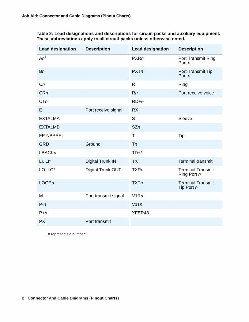
Table 2: Lead designations and descriptions for circuit packs and auxiliary equipment. These abbreviations apply to all circuit packs unless otherwise noted.
Lead designation Description Lead designation Description
An1 PXRn Port Transmit Ring Port n
Bn PXTn Port Transmit Tip Port n
Cn R Ring
CRn Rn Port receive voice
CTn RD+/-
E Port receive signal RX
EXTALMA S Sleeve
EXTALMB SZn
FP-NBPSEL T Tip
GRD Ground Tn
LBACKn TD+/-
LI, LI* Digital Trunk IN TX Terminal transmit
LO, LO* Digital Trunk OUT TXRn Terminal Transmit Ring Port n
LOOPn TXTn Terminal Transmit Tip Port n
M Port transmit signal V1Rn
P-n V1Tn
P+n XFER48
PX Port transmit

Codes for pinout charts
555-245-773 Issue 5 February 2006 3
Table 3: RJ21 25-pair connector, cross-connect Main Distribution Frame (MDF), and backplane pin numbers by wire color designations
Wire color RJ21 25-pair connector pin
Cross-connect (MDF) pin
Backplane pin
W-BL 26 1 102
BL-W 01 2 002
W-O 27 3 103
O-W 02 4 003
W-G 28 5 104
G-W 03 6 004
W-BR 29 7 105
BR-W 04 8 005
W-S 30 9 106
S-W 05 10 006
R-BL 31 11 107
BL-R 06 12 007
R-O 32 13 108
O-R 07 14 008
R-G 33 15 109
G-R 08 16 009
R-BR 34 17 110
BR-R 09 18 010
R-S 35 19 111
S-R 10 20 011
BK-BL 36 21 112
BL-BK 11 22 012
BK-O 37 23 113
O-BK 12 24 013
1 of 3
Job Aid: Connector and Cable Diagrams (Pinout Charts)
4 Connector and Cable Diagrams (Pinout Charts)
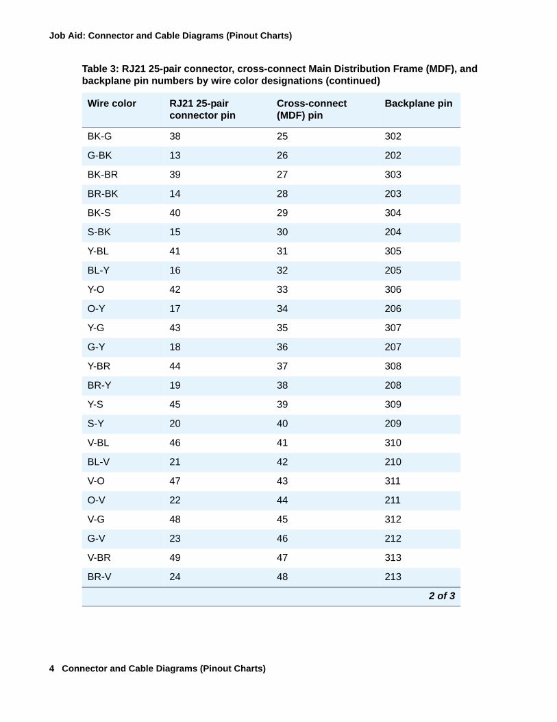
BK-G 38 25 302
G-BK 13 26 202
BK-BR 39 27 303
BR-BK 14 28 203
BK-S 40 29 304
S-BK 15 30 204
Y-BL 41 31 305
BL-Y 16 32 205
Y-O 42 33 306
O-Y 17 34 206
Y-G 43 35 307
G-Y 18 36 207
Y-BR 44 37 308
BR-Y 19 38 208
Y-S 45 39 309
S-Y 20 40 209
V-BL 46 41 310
BL-V 21 42 210
V-O 47 43 311
O-V 22 44 211
V-G 48 45 312
G-V 23 46 212
V-BR 49 47 313
BR-V 24 48 213
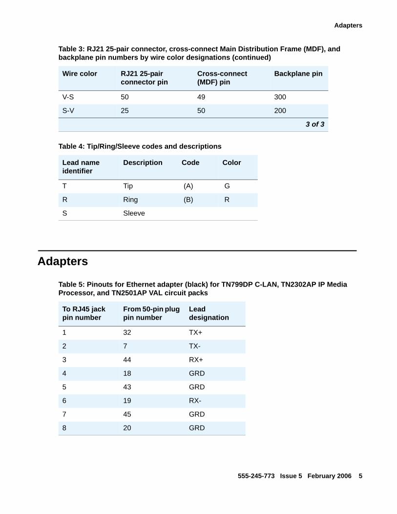
Table 3: RJ21 25-pair connector, cross-connect Main Distribution Frame (MDF), and backplane pin numbers by wire color designations (continued)
Wire color RJ21 25-pair connector pin
Cross-connect (MDF) pin
Backplane pin
2 of 3
Adapters
555-245-773 Issue 5 February 2006 5
Adapters
V-S 50 49 300
S-V 25 50 200
Table 4: Tip/Ring/Sleeve codes and descriptions
Lead name identifier
Description Code Color
T Tip (A) G
R Ring (B) R
S Sleeve
Table 3: RJ21 25-pair connector, cross-connect Main Distribution Frame (MDF), and backplane pin numbers by wire color designations (continued)
Wire color RJ21 25-pair connector pin
Cross-connect (MDF) pin
Backplane pin
3 of 3
Table 5: Pinouts for Ethernet adapter (black) for TN799DP C-LAN, TN2302AP IP Media Processor, and TN2501AP VAL circuit packs
To RJ45 jack pin number
From 50-pin plug pin number
Lead designation
1 32 TX+
2 7 TX-
3 44 RX+
4 18 GRD
5 43 GRD
6 19 RX-
7 45 GRD
8 20 GRD
Job Aid: Connector and Cable Diagrams (Pinout Charts)
6 Connector and Cable Diagrams (Pinout Charts)
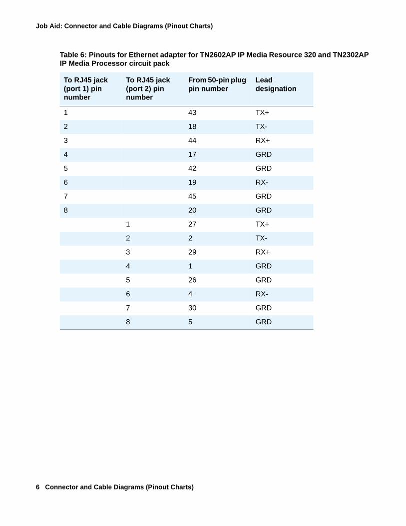
Table 6: Pinouts for Ethernet adapter for TN2602AP IP Media Resource 320 and TN2302AP IP Media Processor circuit pack
To RJ45 jack (port 1) pin number
To RJ45 jack (port 2) pin number
From 50-pin plug pin number
Lead designation
1 43 TX+
2 18 TX-
3 44 RX+
4 17 GRD
5 42 GRD
6 19 RX-
7 45 GRD
8 20 GRD
1 27 TX+
2 2 TX-
3 29 RX+
4 1 GRD
5 26 GRD
6 4 RX-
7 30 GRD
8 5 GRD
Adapters
555-245-773 Issue 5 February 2006 7
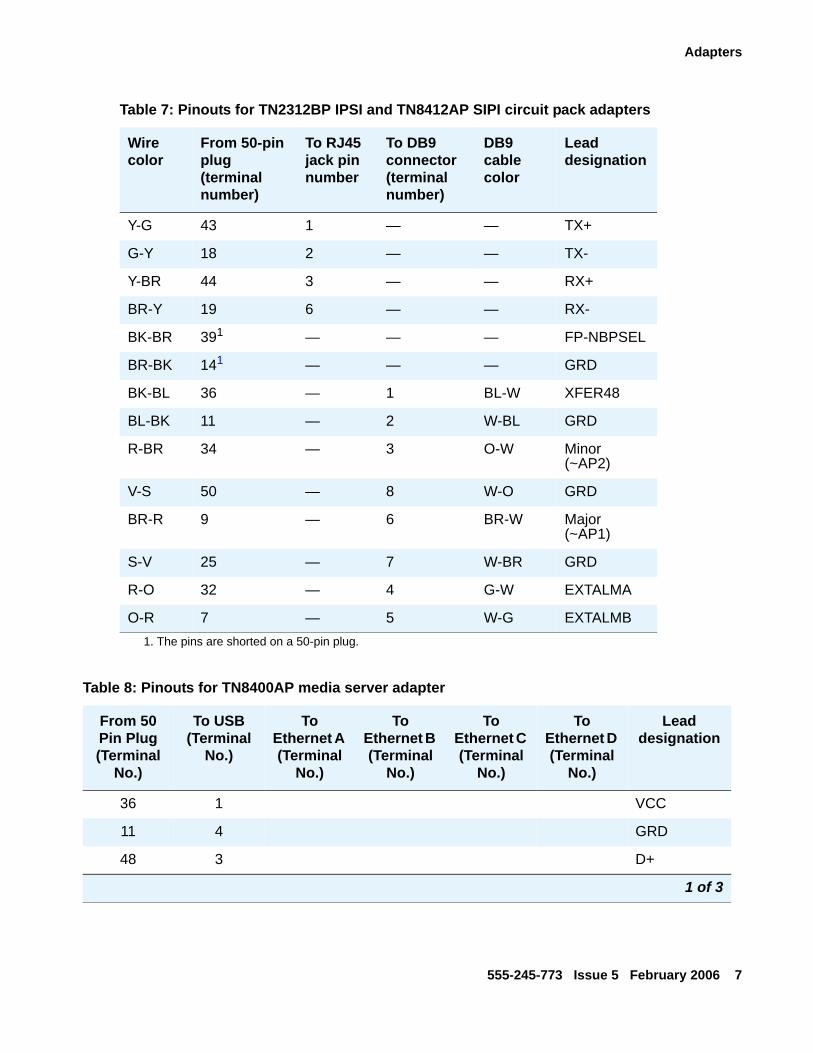
Table 7: Pinouts for TN2312BP IPSI and TN8412AP SIPI circuit pack adapters
Wire color
From 50-pin plug (terminal number)
To RJ45 jack pin number
To DB9 connector (terminal number)
DB9 cable color
Lead designation
Y-G 43 1 — — TX+
G-Y 18 2 — — TX-
Y-BR 44 3 — — RX+
BR-Y 19 6 — — RX-
BK-BR 391
1. The pins are shorted on a 50-pin plug.
— — — FP-NBPSEL
BR-BK 141 — — — GRD
BK-BL 36 — 1 BL-W XFER48
BL-BK 11 — 2 W-BL GRD
R-BR 34 — 3 O-W Minor (~AP2)
V-S 50 — 8 W-O GRD
BR-R 9 — 6 BR-W Major (~AP1)
S-V 25 — 7 W-BR GRD
R-O 32 — 4 G-W EXTALMA
O-R 7 — 5 W-G EXTALMB
Table 8: Pinouts for TN8400AP media server adapter
From 50 Pin Plug (Terminal
No.)
To USB (Terminal
No.)
To Ethernet A (Terminal
No.)
To Ethernet B (Terminal
No.)
To Ethernet C (Terminal
No.)
To Ethernet D (Terminal
No.)
Lead designation
36 1 VCC
11 4 GRD
48 3 D+
1 of 3
Job Aid: Connector and Cable Diagrams (Pinout Charts)
8 Connector and Cable Diagrams (Pinout Charts)
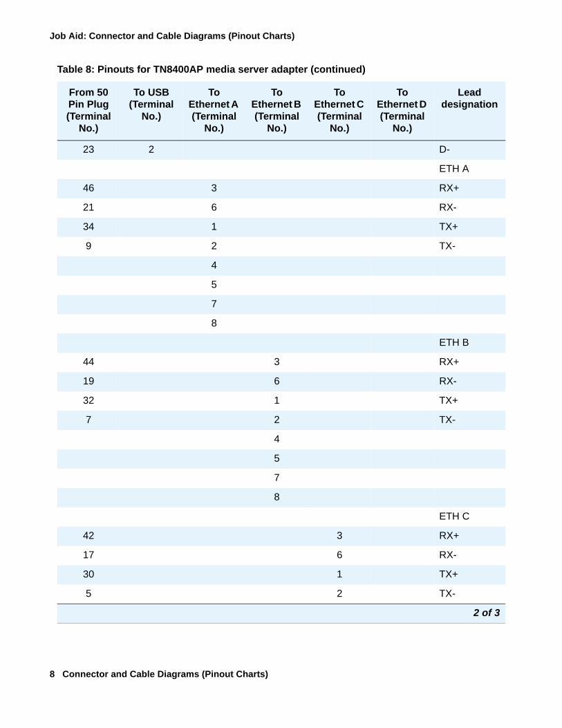
23 2 D-
ETH A
46 3 RX+
21 6 RX-
34 1 TX+
9 2 TX-
4
5
7
8
ETH B
44 3 RX+
19 6 RX-
32 1 TX+
7 2 TX-
4
5
7
8
ETH C
42 3 RX+
17 6 RX-
30 1 TX+
5 2 TX-
Table 8: Pinouts for TN8400AP media server adapter (continued)
From 50 Pin Plug (Terminal
No.)
To USB (Terminal
No.)
To Ethernet A (Terminal
No.)
To Ethernet B (Terminal
No.)
To Ethernet C (Terminal
No.)
To Ethernet D (Terminal
No.)
Lead designation
2 of 3

Adapters
555-245-773 Issue 5 February 2006 9
4
5
7
8
ETH D
38 3 RX+
13 6 RX-
26 1 TX+
1 2 TX-
4
5
7
8
Table 8: Pinouts for TN8400AP media server adapter (continued)
From 50 Pin Plug (Terminal
No.)
To USB (Terminal
No.)
To Ethernet A (Terminal
No.)
To Ethernet B (Terminal
No.)
To Ethernet C (Terminal
No.)
To Ethernet D (Terminal
No.)
Lead designation
3 of 3
Job Aid: Connector and Cable Diagrams (Pinout Charts)
10 Connector and Cable Diagrams (Pinout Charts)
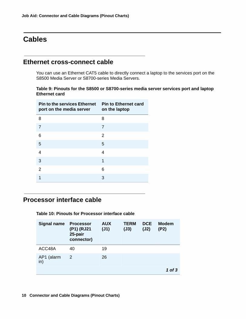
Cables
Ethernet cross-connect cableYou can use an Ethernet CAT5 cable to directly connect a laptop to the services port on the S8500 Media Server or S8700-series Media Servers.
Processor interface cable
Table 9: Pinouts for the S8500 or S8700-series media server services port and laptop Ethernet card
Pin to the services Ethernet port on the media server
Pin to Ethernet card on the laptop
8 8
7 7
6 2
5 5
4 4
3 1
2 6
1 3
Table 10: Pinouts for Processor interface cable
Signal name Processor (P1) (RJ21 25-pair connector)
AUX (J1)
TERM (J3)
DCE (J2)
Modem (P2)
ACC48A 40 19
AP1 (alarm in)
2 26
1 of 3
Cables
555-245-773 Issue 5 February 2006 11
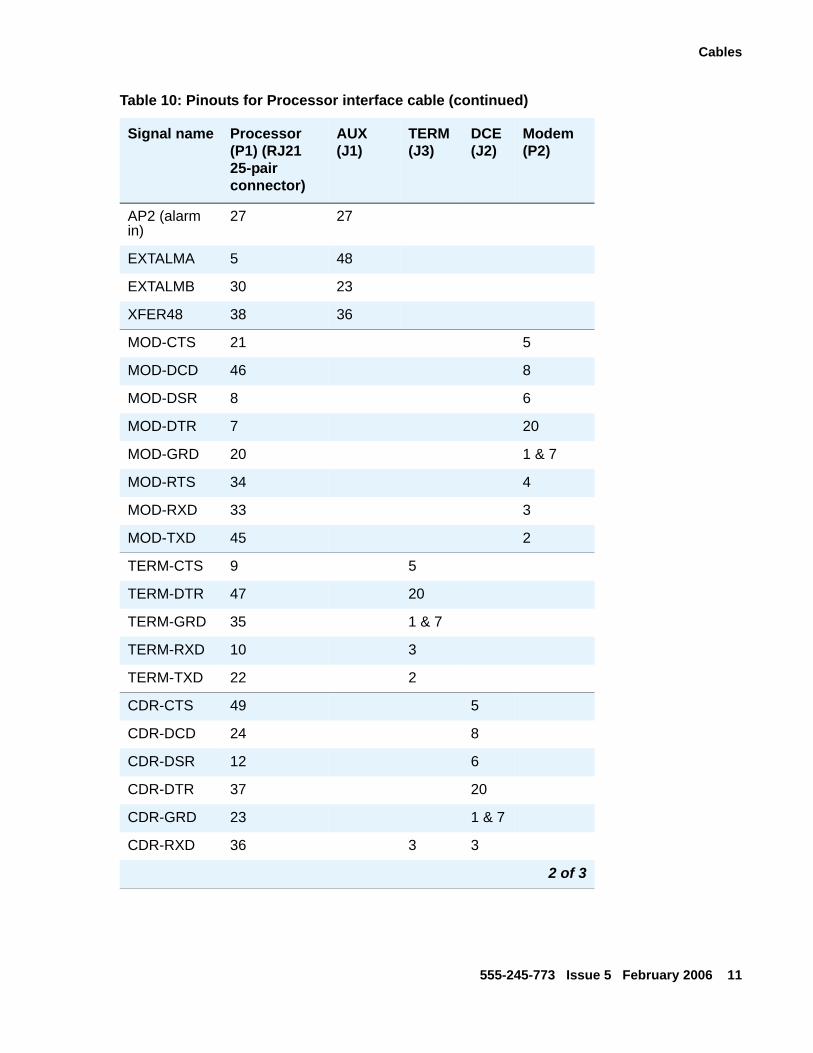
AP2 (alarm in)
27 27
EXTALMA 5 48
EXTALMB 30 23
XFER48 38 36
MOD-CTS 21 5
MOD-DCD 46 8
MOD-DSR 8 6
MOD-DTR 7 20
MOD-GRD 20 1 & 7
MOD-RTS 34 4
MOD-RXD 33 3
MOD-TXD 45 2
TERM-CTS 9 5
TERM-DTR 47 20
TERM-GRD 35 1 & 7
TERM-RXD 10 3
TERM-TXD 22 2
CDR-CTS 49 5
CDR-DCD 24 8
CDR-DSR 12 6
CDR-DTR 37 20
CDR-GRD 23 1 & 7
CDR-RXD 36 3 3
Table 10: Pinouts for Processor interface cable (continued)
Signal name Processor (P1) (RJ21 25-pair connector)
AUX (J1)
TERM (J3)
DCE (J2)
Modem (P2)
2 of 3

Job Aid: Connector and Cable Diagrams (Pinout Charts)
12 Connector and Cable Diagrams (Pinout Charts)
CDR-TXD 48 2 2
GRD 25, 50 1-7, 11-17, 44-46
1, 7 1, 7 1, 7
Table 10: Pinouts for Processor interface cable (continued)
Signal name Processor (P1) (RJ21 25-pair connector)
AUX (J1)
TERM (J3)
DCE (J2)
Modem (P2)
3 of 3
Cables
555-245-773 Issue 5 February 2006 13
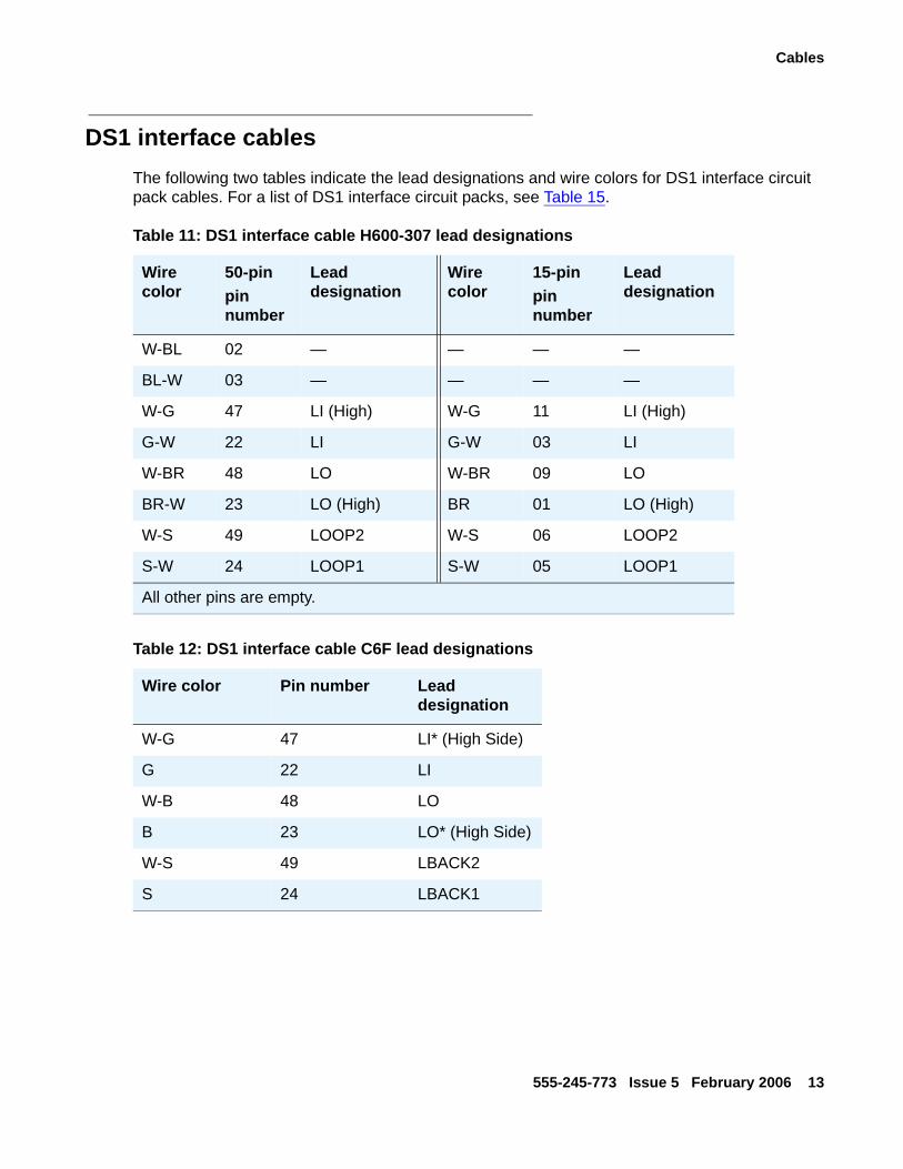
DS1 interface cablesThe following two tables indicate the lead designations and wire colors for DS1 interface circuit pack cables. For a list of DS1 interface circuit packs, see Table 15.
Table 11: DS1 interface cable H600-307 lead designations
Wire color
50-pinpin number
Lead designation
Wire color
15-pinpin number
Lead designation
W-BL 02 — — — —
BL-W 03 — — — —
W-G 47 LI (High) W-G 11 LI (High)
G-W 22 LI G-W 03 LI
W-BR 48 LO W-BR 09 LO
BR-W 23 LO (High) BR 01 LO (High)
W-S 49 LOOP2 W-S 06 LOOP2
S-W 24 LOOP1 S-W 05 LOOP1
All other pins are empty.
Table 12: DS1 interface cable C6F lead designations
Wire color Pin number Lead designation
W-G 47 LI* (High Side)
G 22 LI
W-B 48 LO
B 23 LO* (High Side)
W-S 49 LBACK2
S 24 LBACK1
Job Aid: Connector and Cable Diagrams (Pinout Charts)
14 Connector and Cable Diagrams (Pinout Charts)
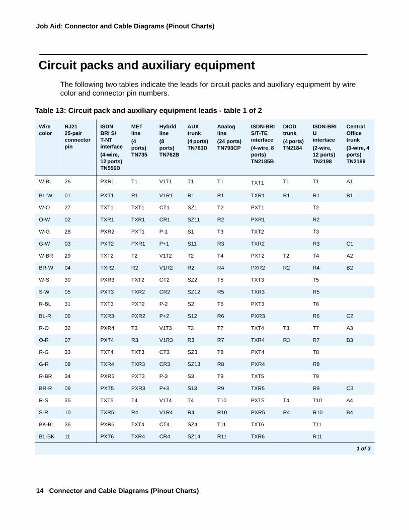
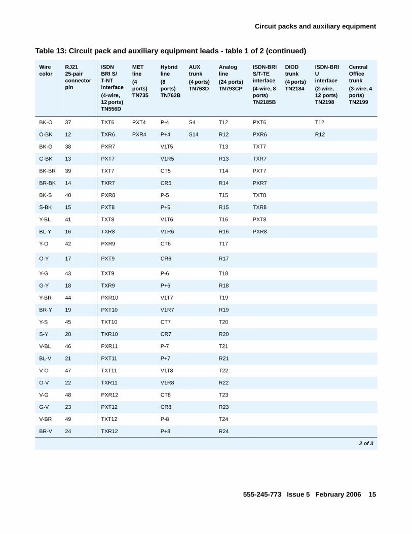
Circuit packs and auxiliary equipmentThe following two tables indicate the leads for circuit packs and auxiliary equipment by wire color and connector pin numbers.
Table 13: Circuit pack and auxiliary equipment leads - table 1 of 2
Wire color
RJ21 25-pair connector pin
ISDN BRI S/T-NT interface(4-wire, 12 ports) TN556D
MET line(4 ports) TN735
Hybrid line (8 ports) TN762B
AUX trunk (4 ports) TN763D
Analog line(24 ports) TN793CP
ISDN-BRI S/T-TE interface(4-wire, 8 ports) TN2185B
DIOD trunk (4 ports) TN2184
ISDN-BRI U interface(2-wire, 12 ports) TN2198
Central Office trunk(3-wire, 4 ports) TN2199
W-BL 26 PXR1 T1 V1T1 T1 T1 TXT1 T1 T1 A1
BL-W 01 PXT1 R1 V1R1 R1 R1 TXR1 R1 R1 B1
W-O 27 TXT1 TXT1 CT1 SZ1 T2 PXT1 T2
O-W 02 TXR1 TXR1 CR1 SZ11 R2 PXR1 R2
W-G 28 PXR2 PXT1 P-1 S1 T3 TXT2 T3
G-W 03 PXT2 PXR1 P+1 S11 R3 TXR2 R3 C1
W-BR 29 TXT2 T2 V1T2 T2 T4 PXT2 T2 T4 A2
BR-W 04 TXR2 R2 V1R2 R2 R4 PXR2 R2 R4 B2
W-S 30 PXR3 TXT2 CT2 SZ2 T5 TXT3 T5
S-W 05 PXT3 TXR2 CR2 SZ12 R5 TXR3 R5
R-BL 31 TXT3 PXT2 P-2 S2 T6 PXT3 T6
BL-R 06 TXR3 PXR2 P+2 S12 R6 PXR3 R6 C2
R-O 32 PXR4 T3 V1T3 T3 T7 TXT4 T3 T7 A3
O-R 07 PXT4 R3 V1R3 R3 R7 TXR4 R3 R7 B3
R-G 33 TXT4 TXT3 CT3 SZ3 T8 PXT4 T8
G-R 08 TXR4 TXR3 CR3 SZ13 R8 PXR4 R8
R-BR 34 PXR5 PXT3 P-3 S3 T9 TXT5 T9
BR-R 09 PXT5 PXR3 P+3 S13 R9 TXR5 R9 C3
R-S 35 TXT5 T4 V1T4 T4 T10 PXT5 T4 T10 A4
S-R 10 TXR5 R4 V1R4 R4 R10 PXR5 R4 R10 B4
BK-BL 36 PXR6 TXT4 CT4 SZ4 T11 TXT6 T11
BL-BK 11 PXT6 TXR4 CR4 SZ14 R11 TXR6 R11
1 of 3
Circuit packs and auxiliary equipment
555-245-773 Issue 5 February 2006 15
BK-O 37 TXT6 PXT4 P-4 S4 T12 PXT6 T12
O-BK 12 TXR6 PXR4 P+4 S14 R12 PXR6 R12
BK-G 38 PXR7 V1T5 T13 TXT7
G-BK 13 PXT7 V1R5 R13 TXR7
BK-BR 39 TXT7 CT5 T14 PXT7
BR-BK 14 TXR7 CR5 R14 PXR7
BK-S 40 PXR8 P-5 T15 TXT8
S-BK 15 PXT8 P+5 R15 TXR8
Y-BL 41 TXT8 V1T6 T16 PXT8
BL-Y 16 TXR8 V1R6 R16 PXR8
Y-O 42 PXR9 CT6 T17
O-Y 17 PXT9 CR6 R17
Y-G 43 TXT9 P-6 T18
G-Y 18 TXR9 P+6 R18
Y-BR 44 PXR10 V1T7 T19
BR-Y 19 PXT10 V1R7 R19
Y-S 45 TXT10 CT7 T20
S-Y 20 TXR10 CR7 R20
V-BL 46 PXR11 P-7 T21
BL-V 21 PXT11 P+7 R21
V-O 47 TXT11 V1T8 T22
O-V 22 TXR11 V1R8 R22
V-G 48 PXR12 CT8 T23
G-V 23 PXT12 CR8 R23
V-BR 49 TXT12 P-8 T24
BR-V 24 TXR12 P+8 R24
Table 13: Circuit pack and auxiliary equipment leads - table 1 of 2 (continued)
Wire color
RJ21 25-pair connector pin
ISDN BRI S/T-NT interface(4-wire, 12 ports) TN556D
MET line(4 ports) TN735
Hybrid line (8 ports) TN762B
AUX trunk (4 ports) TN763D
Analog line(24 ports) TN793CP
ISDN-BRI S/T-TE interface(4-wire, 8 ports) TN2185B
DIOD trunk (4 ports) TN2184
ISDN-BRI U interface(2-wire, 12 ports) TN2198
Central Office trunk(3-wire, 4 ports) TN2199
2 of 3

Job Aid: Connector and Cable Diagrams (Pinout Charts)
16 Connector and Cable Diagrams (Pinout Charts)
V-S 50 GRD GRD GRD GRD GRD GRD GRD GRD GRD
S-V 25 GRD GRD GRD GRD GRD GRD GRD GRD GRD
Table 13: Circuit pack and auxiliary equipment leads - table 1 of 2 (continued)
Wire color
RJ21 25-pair connector pin
ISDN BRI S/T-NT interface(4-wire, 12 ports) TN556D
MET line(4 ports) TN735
Hybrid line (8 ports) TN762B
AUX trunk (4 ports) TN763D
Analog line(24 ports) TN793CP
ISDN-BRI S/T-TE interface(4-wire, 8 ports) TN2185B
DIOD trunk (4 ports) TN2184
ISDN-BRI U interface(2-wire, 12 ports) TN2198
Central Office trunk(3-wire, 4 ports) TN2199
3 of 3
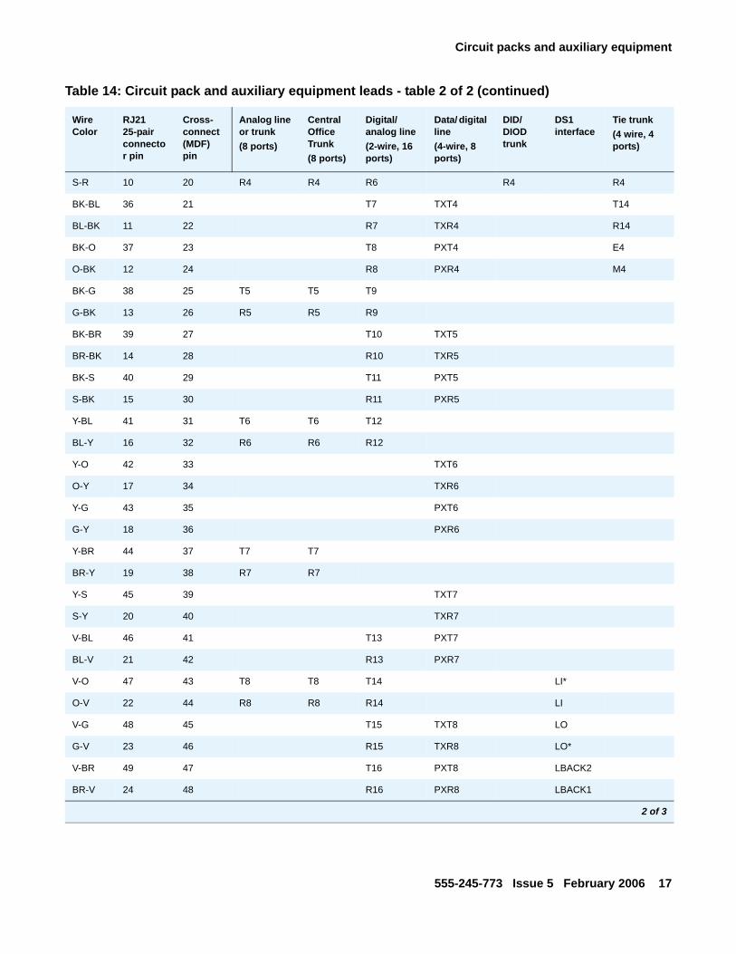
Table 14: Circuit pack and auxiliary equipment leads - table 2 of 2
Wire Color
RJ21 25-pair connector pin
Cross- connect (MDF) pin
Analog line or trunk (8 ports)
Central Office Trunk(8 ports)
Digital/analog line(2-wire, 16 ports)
Data/ digital line(4-wire, 8 ports)
DID/DIOD trunk
DS1 interface
Tie trunk (4 wire, 4 ports)
W-BL 26 1 T1 T1 T1 T1 T1
BL-W 01 2 R1 R1 R1 R1 R1
W-O 27 3 T2 TXT1 T11
O-W 02 4 R2 TXR1 R11
W-G 28 5 T3 PXT1 E1
G-W 03 6 R3 PXR1 M1
W-BR 29 7 T2 T2 T4 T2 T2
BR-W 04 8 R2 R2 R4 R2 R2
W-S 30 9 TXT2 T12
S-W 05 10 TXR2 R12
R-BL 31 11 PXT2 E2
BL-R 06 12 PXR2 M2
R-O 32 13 T3 T3 T3 T3
O-R 07 14 R3 R3 R3 R3
R-G 33 15 TXT3 T13
G-R 08 16 TXR3 R13
R-BR 34 17 T5 PXT3 E3
BR-R 09 18 R5 PXR3 M3
R-S 35 19 T4 T4 T6 T4 T4
1 of 3
Circuit packs and auxiliary equipment
555-245-773 Issue 5 February 2006 17
S-R 10 20 R4 R4 R6 R4 R4
BK-BL 36 21 T7 TXT4 T14
BL-BK 11 22 R7 TXR4 R14
BK-O 37 23 T8 PXT4 E4
O-BK 12 24 R8 PXR4 M4
BK-G 38 25 T5 T5 T9
G-BK 13 26 R5 R5 R9
BK-BR 39 27 T10 TXT5
BR-BK 14 28 R10 TXR5
BK-S 40 29 T11 PXT5
S-BK 15 30 R11 PXR5
Y-BL 41 31 T6 T6 T12
BL-Y 16 32 R6 R6 R12
Y-O 42 33 TXT6
O-Y 17 34 TXR6
Y-G 43 35 PXT6
G-Y 18 36 PXR6
Y-BR 44 37 T7 T7
BR-Y 19 38 R7 R7
Y-S 45 39 TXT7
S-Y 20 40 TXR7
V-BL 46 41 T13 PXT7
BL-V 21 42 R13 PXR7
V-O 47 43 T8 T8 T14 LI*
O-V 22 44 R8 R8 R14 LI
V-G 48 45 T15 TXT8 LO
G-V 23 46 R15 TXR8 LO*
V-BR 49 47 T16 PXT8 LBACK2
BR-V 24 48 R16 PXR8 LBACK1
Table 14: Circuit pack and auxiliary equipment leads - table 2 of 2 (continued)
Wire Color
RJ21 25-pair connector pin
Cross- connect (MDF) pin
Analog line or trunk (8 ports)
Central Office Trunk(8 ports)
Digital/analog line(2-wire, 16 ports)
Data/ digital line(4-wire, 8 ports)
DID/DIOD trunk
DS1 interface
Tie trunk (4 wire, 4 ports)
2 of 3

Job Aid: Connector and Cable Diagrams (Pinout Charts)
18 Connector and Cable Diagrams (Pinout Charts)
V-S 50 49 GRD GRD GRD GRD GRD GRD GRD
S-V 25 50 GRD GRD GRD GRD GRD GRD GRD
Table 14: Circuit pack and auxiliary equipment leads - table 2 of 2 (continued)
Wire Color
RJ21 25-pair connector pin
Cross- connect (MDF) pin
Analog line or trunk (8 ports)
Central Office Trunk(8 ports)
Digital/analog line(2-wire, 16 ports)
Data/ digital line(4-wire, 8 ports)
DID/DIOD trunk
DS1 interface
Tie trunk (4 wire, 4 ports)
3 of 3
Table 15: Circuit pack name cross-reference for Table 14
Analog line or trunk (8 ports)
Central office trunk(8 ports)
Data/ digital line(4-wire, 8 ports)
DCP Digital line(2 wire, 8 ports)
DID/DIOD trunk
Digital/analog line(2-wire, 16 ports)
DS1 interface
Tie trunk(4 wire, 4 ports)
TN769 TN429D TN726B TN2214CP TN429D TN479 TN464HP TN760E
TN797 TN438B TN754C TN2224CP TN436B TN746B TN767E TN2140B
TN465C TN459B TN791 TN2207 TN2209
TN747B TN753B TN2181 TN2313AP
TN2138 TN2139 TN2183 TN2464CP
TN2147C TN2146 TN2215
TN2308
Individual circuit packs
555-245-773 Issue 5 February 2006 19
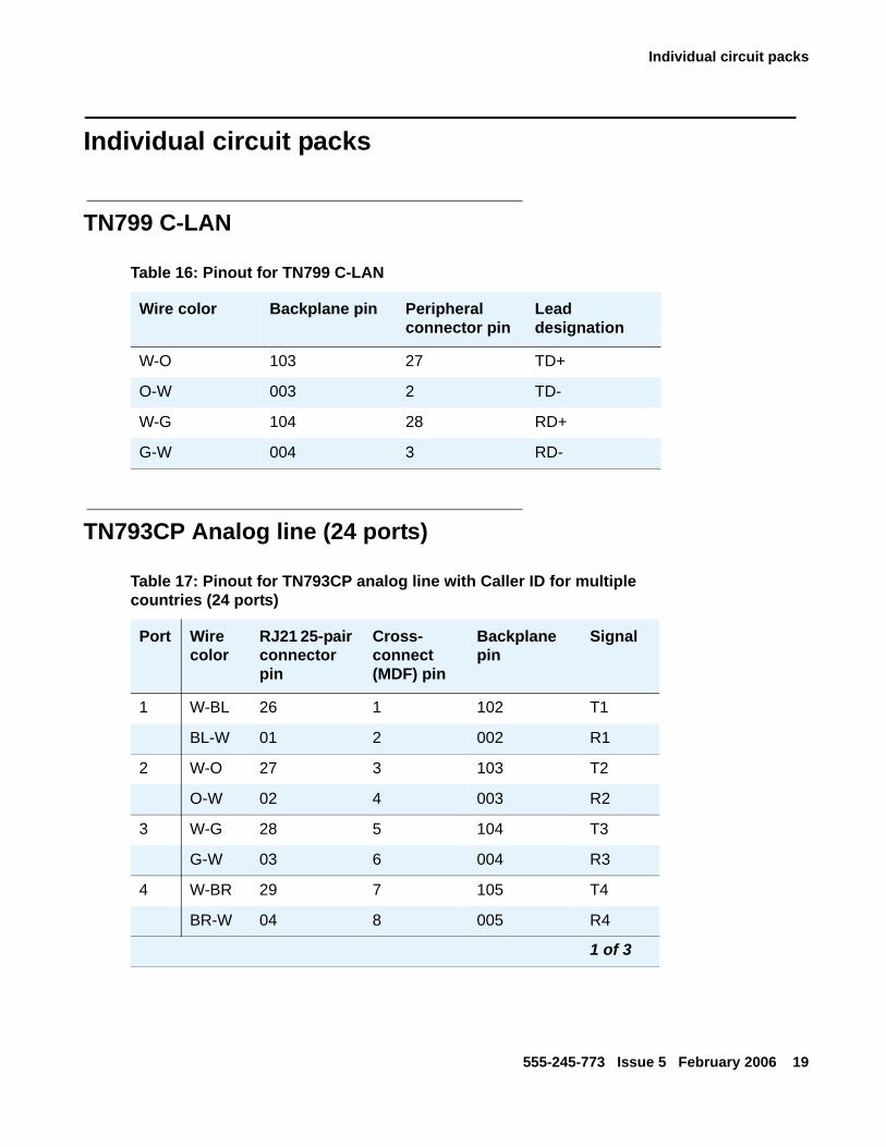
Individual circuit packs
TN799 C-LAN
TN793CP Analog line (24 ports)
Table 16: Pinout for TN799 C-LAN
Wire color Backplane pin Peripheral connector pin
Lead designation
W-O 103 27 TD+
O-W 003 2 TD-
W-G 104 28 RD+
G-W 004 3 RD-
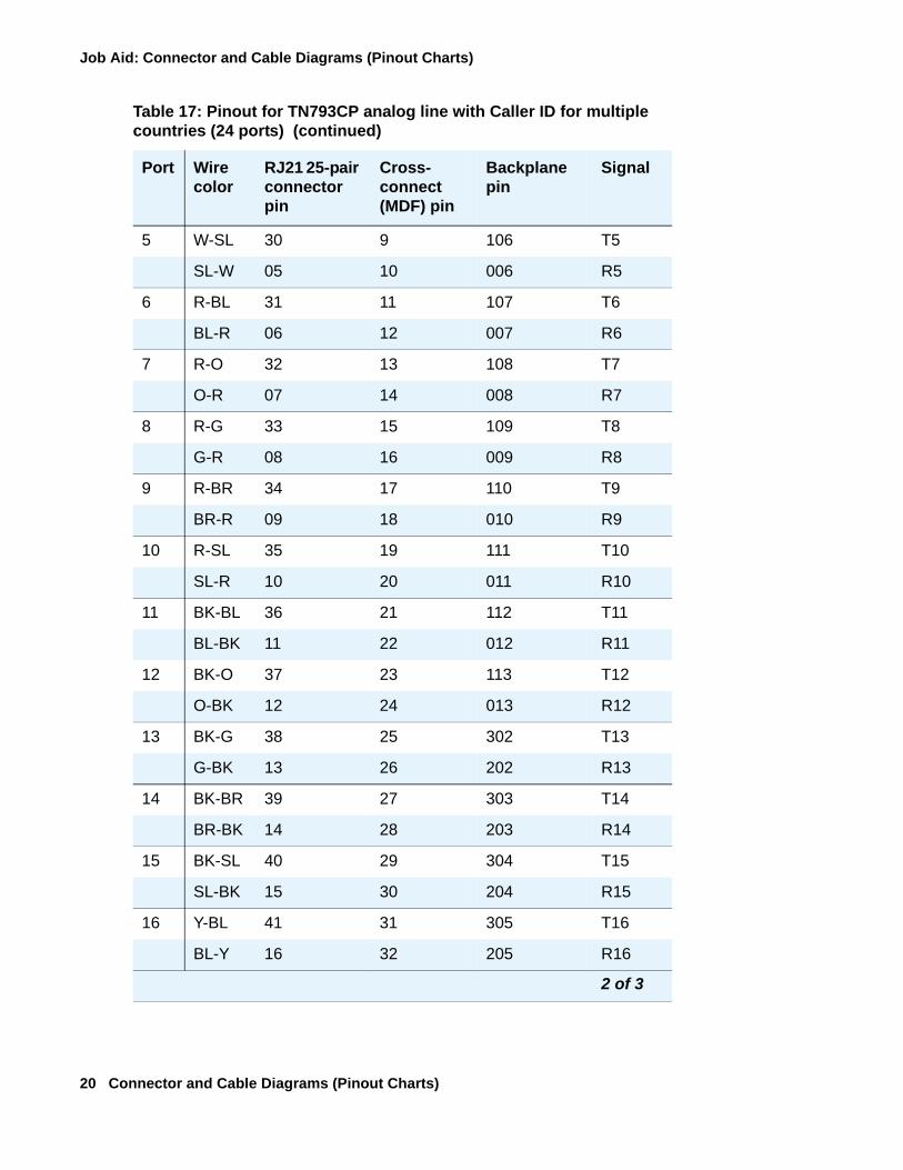
Table 17: Pinout for TN793CP analog line with Caller ID for multiple countries (24 ports)
Port Wire color
RJ21 25-pair connector pin
Cross- connect (MDF) pin
Backplane pin
Signal
1 W-BL 26 1 102 T1
BL-W 01 2 002 R1
2 W-O 27 3 103 T2
O-W 02 4 003 R2
3 W-G 28 5 104 T3
G-W 03 6 004 R3
4 W-BR 29 7 105 T4
BR-W 04 8 005 R4
1 of 3
Job Aid: Connector and Cable Diagrams (Pinout Charts)
20 Connector and Cable Diagrams (Pinout Charts)
5 W-SL 30 9 106 T5
SL-W 05 10 006 R5
6 R-BL 31 11 107 T6
BL-R 06 12 007 R6
7 R-O 32 13 108 T7
O-R 07 14 008 R7
8 R-G 33 15 109 T8
G-R 08 16 009 R8
9 R-BR 34 17 110 T9
BR-R 09 18 010 R9
10 R-SL 35 19 111 T10
SL-R 10 20 011 R10
11 BK-BL 36 21 112 T11
BL-BK 11 22 012 R11
12 BK-O 37 23 113 T12
O-BK 12 24 013 R12
13 BK-G 38 25 302 T13
G-BK 13 26 202 R13
14 BK-BR 39 27 303 T14
BR-BK 14 28 203 R14
15 BK-SL 40 29 304 T15
SL-BK 15 30 204 R15
16 Y-BL 41 31 305 T16
BL-Y 16 32 205 R16
Table 17: Pinout for TN793CP analog line with Caller ID for multiple countries (24 ports) (continued)
Port Wire color
RJ21 25-pair connector pin
Cross- connect (MDF) pin
Backplane pin
Signal
2 of 3

Individual circuit packs
555-245-773 Issue 5 February 2006 21
17 Y-O 42 33 306 T17
O-Y 17 34 206 R17
18 Y-G 43 35 307 T18
G-Y 18 36 207 R18
19 Y-BR 44 37 308 T19
BR-Y 19 38 208 R19
20 Y-SL 45 39 309 T20
SL-Y 20 40 209 R20
21 V-BL 46 41 310 T21
BL-V 21 42 210 R21
22 V-O 47 43 311 T22
O-V 22 44 211 R22
23 V-G 48 45 312 T23
G-V 23 46 212 R23
24 V-BR 49 47 313 T24
BR-V 24 48 213 R24
25 V/SL 50 49 314
SL/V 25 50 214
Table 17: Pinout for TN793CP analog line with Caller ID for multiple countries (24 ports) (continued)
Port Wire color
RJ21 25-pair connector pin
Cross- connect (MDF) pin
Backplane pin
Signal
3 of 3

Job Aid: Connector and Cable Diagrams (Pinout Charts)
22 Connector and Cable Diagrams (Pinout Charts)
TN2158B ISDN-BRI S/T-TE interface (4-wire, 8 ports)
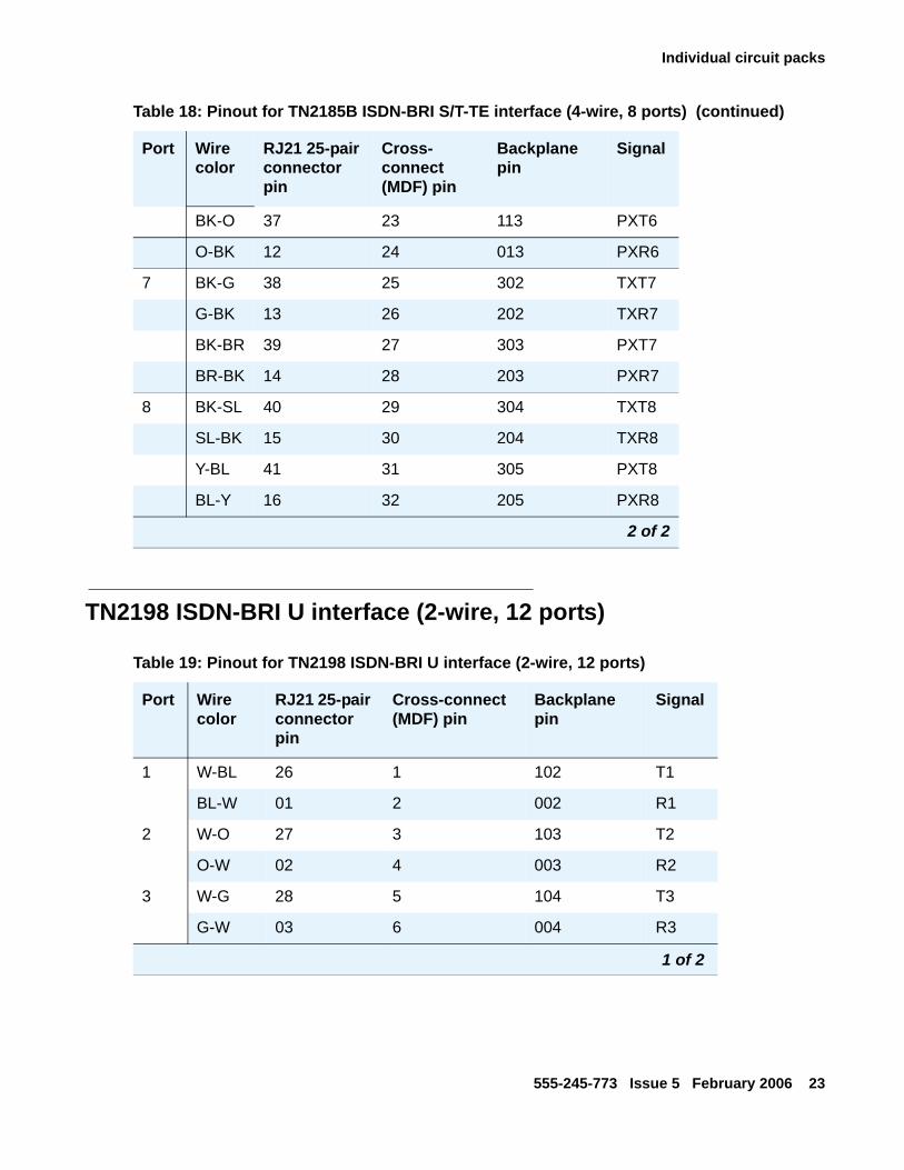
Table 18: Pinout for TN2185B ISDN-BRI S/T-TE interface (4-wire, 8 ports)
Port Wire color
RJ21 25-pair connector pin
Cross- connect (MDF) pin
Backplane pin
Signal
1 W-BL 26 1 102 TXT1
BL-W 01 2 002 TXR1
W-O 27 3 103 PXT1
O-W 02 4 003 PXR1
2 W-G 28 5 104 TXT2
G-W 03 6 004 TXR2
W-BR 29 7 105 PXT2
BR-W 04 8 005 PXR2
3 W-SL 30 9 106 TXT3
SL-W 05 10 006 TXR3
R-BL 31 11 107 PXT3
BL-R 06 12 007 PXR3
4 R-O 32 13 108 TXT4
O-R 07 14 008 TXR4
R-G 33 15 109 PXT4
G-R 08 16 009 PXR4
5 R-BR 34 17 110 TXT5
BR-R 09 18 010 TXR5
R-SL 35 19 111 PXT5
SL-R 10 20 011 PXR5
6 BK-BL 36 21 112 TXT6
BL-BK 11 22 012 TXR6
1 of 2
Individual circuit packs
555-245-773 Issue 5 February 2006 23
TN2198 ISDN-BRI U interface (2-wire, 12 ports)
BK-O 37 23 113 PXT6
O-BK 12 24 013 PXR6
7 BK-G 38 25 302 TXT7
G-BK 13 26 202 TXR7
BK-BR 39 27 303 PXT7
BR-BK 14 28 203 PXR7
8 BK-SL 40 29 304 TXT8
SL-BK 15 30 204 TXR8
Y-BL 41 31 305 PXT8
BL-Y 16 32 205 PXR8
Table 18: Pinout for TN2185B ISDN-BRI S/T-TE interface (4-wire, 8 ports) (continued)
Port Wire color
RJ21 25-pair connector pin
Cross- connect (MDF) pin
Backplane pin
Signal
2 of 2
Table 19: Pinout for TN2198 ISDN-BRI U interface (2-wire, 12 ports)
Port Wire color
RJ21 25-pair connector pin
Cross-connect (MDF) pin
Backplane pin
Signal
1 W-BL 26 1 102 T1
BL-W 01 2 002 R1
2 W-O 27 3 103 T2
O-W 02 4 003 R2
3 W-G 28 5 104 T3
G-W 03 6 004 R3
1 of 2
Job Aid: Connector and Cable Diagrams (Pinout Charts)
24 Connector and Cable Diagrams (Pinout Charts)
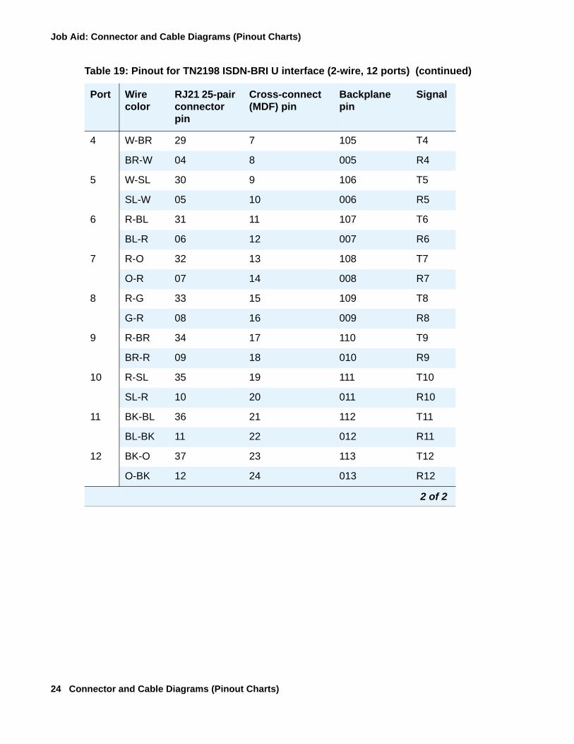
4 W-BR 29 7 105 T4
BR-W 04 8 005 R4
5 W-SL 30 9 106 T5
SL-W 05 10 006 R5
6 R-BL 31 11 107 T6
BL-R 06 12 007 R6
7 R-O 32 13 108 T7
O-R 07 14 008 R7
8 R-G 33 15 109 T8
G-R 08 16 009 R8
9 R-BR 34 17 110 T9
BR-R 09 18 010 R9
10 R-SL 35 19 111 T10
SL-R 10 20 011 R10
11 BK-BL 36 21 112 T11
BL-BK 11 22 012 R11
12 BK-O 37 23 113 T12
O-BK 12 24 013 R12
Table 19: Pinout for TN2198 ISDN-BRI U interface (2-wire, 12 ports) (continued)
Port Wire color
RJ21 25-pair connector pin
Cross-connect (MDF) pin
Backplane pin
Signal
2 of 2
Connectors
555-245-773 Issue 5 February 2006 25
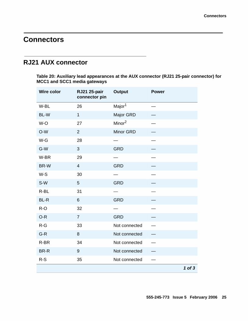
Connectors
RJ21 AUX connector
Table 20: Auxiliary lead appearances at the AUX connector (RJ21 25-pair connector) for MCC1 and SCC1 media gateways
Wire color RJ21 25-pair connector pin
Output Power
W-BL 26 Major1 —
BL-W 1 Major GRD —
W-O 27 Minor2 —
O-W 2 Minor GRD —
W-G 28 — —
G-W 3 GRD —
W-BR 29 — —
BR-W 4 GRD —
W-S 30 — —
S-W 5 GRD —
R-BL 31 — —
BL-R 6 GRD —
R-O 32 — —
O-R 7 GRD —
R-G 33 Not connected —
G-R 8 Not connected —
R-BR 34 Not connected —
BR-R 9 Not connected —
R-S 35 Not connected —
1 of 3
Job Aid: Connector and Cable Diagrams (Pinout Charts)
26 Connector and Cable Diagrams (Pinout Charts)
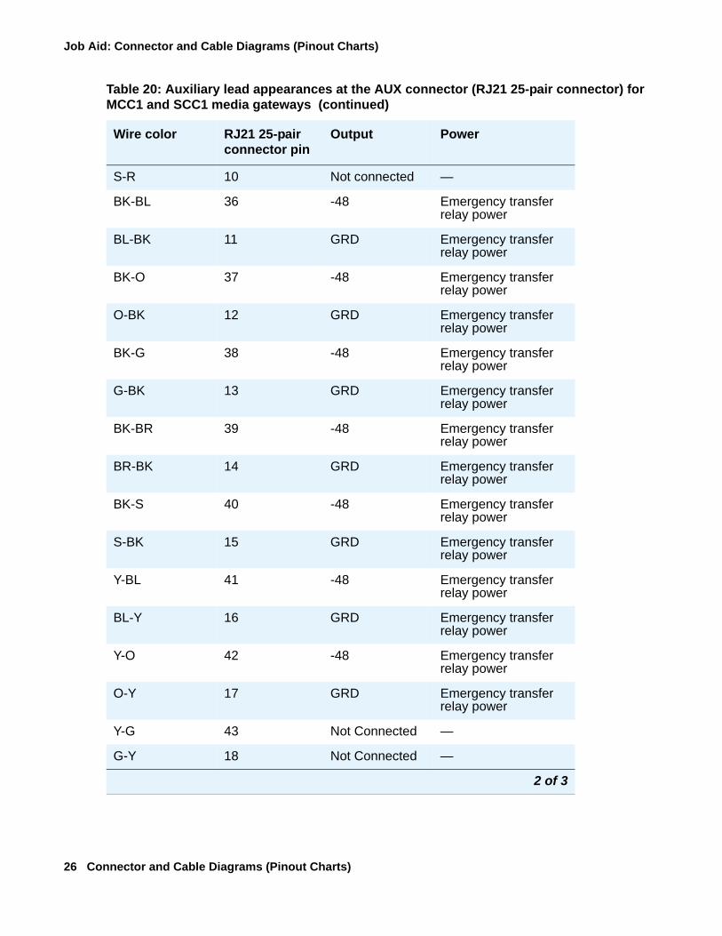
S-R 10 Not connected —
BK-BL 36 -48 Emergency transfer relay power
BL-BK 11 GRD Emergency transfer relay power
BK-O 37 -48 Emergency transfer relay power
O-BK 12 GRD Emergency transfer relay power
BK-G 38 -48 Emergency transfer relay power
G-BK 13 GRD Emergency transfer relay power
BK-BR 39 -48 Emergency transfer relay power
BR-BK 14 GRD Emergency transfer relay power
BK-S 40 -48 Emergency transfer relay power
S-BK 15 GRD Emergency transfer relay power
Y-BL 41 -48 Emergency transfer relay power
BL-Y 16 GRD Emergency transfer relay power
Y-O 42 -48 Emergency transfer relay power
O-Y 17 GRD Emergency transfer relay power
Y-G 43 Not Connected —
G-Y 18 Not Connected —
Table 20: Auxiliary lead appearances at the AUX connector (RJ21 25-pair connector) for MCC1 and SCC1 media gateways (continued)
Wire color RJ21 25-pair connector pin
Output Power
2 of 3

Connectors
555-245-773 Issue 5 February 2006 27
Y-BR 44 GRD AUX power for attendant consoles
BR-Y 19 -48 AUX power for attendant consoles
Y-S 45 GRD AUX power for attendant consoles
S-Y 20 -48 AUX power for attendant consoles
V-BL 46 GRD AUX power for attendant consoles
BL-V 21 -48 AUX power for attendant consoles
V-O 47 Not connected —
O-V 22 Not connected —
V-G 48 Ext alarm A3 —
G-V 23 Ext alarm return —
V-BR 49 Not connected —
BR-V 24 Not connected —
V-S 50 INADS tip —
S-V 25 INADS ring —
1. External major alarm input pair from an external isolated contact closure (60 VDC max, 5 mA max)
2. External minor alarm input pair from an external isolated contact closure (60 VDC max, 5 mA max)
3. Output alarm from the Media Gateway, via a contact closure, to the equipment room alarm light or bell
Table 20: Auxiliary lead appearances at the AUX connector (RJ21 25-pair connector) for MCC1 and SCC1 media gateways (continued)
Wire color RJ21 25-pair connector pin
Output Power
3 of 3
Job Aid: Connector and Cable Diagrams (Pinout Charts)
28 Connector and Cable Diagrams (Pinout Charts)
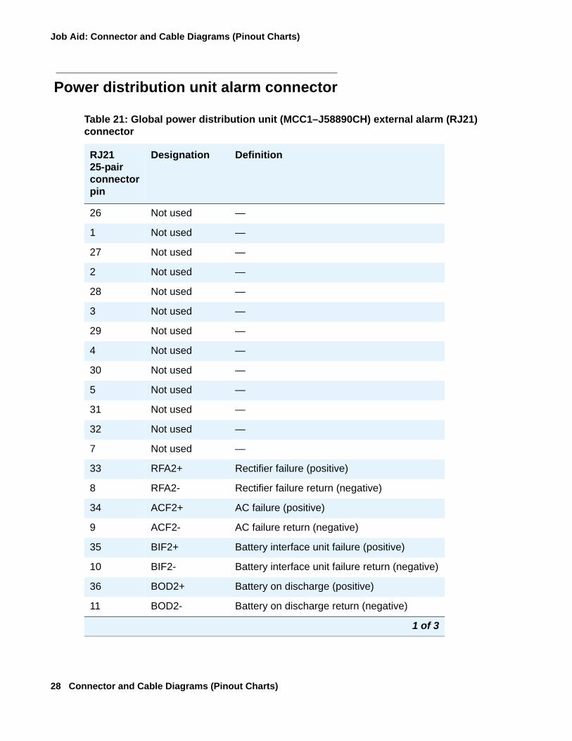
Power distribution unit alarm connector
Table 21: Global power distribution unit (MCC1–J58890CH) external alarm (RJ21) connector
RJ21 25-pair connector pin
Designation Definition
26 Not used —
1 Not used —
27 Not used —
2 Not used —
28 Not used —
3 Not used —
29 Not used —
4 Not used —
30 Not used —
5 Not used —
31 Not used —
32 Not used —
7 Not used —
33 RFA2+ Rectifier failure (positive)
8 RFA2- Rectifier failure return (negative)
34 ACF2+ AC failure (positive)
9 ACF2- AC failure return (negative)
35 BIF2+ Battery interface unit failure (positive)
10 BIF2- Battery interface unit failure return (negative)
36 BOD2+ Battery on discharge (positive)
11 BOD2- Battery on discharge return (negative)
1 of 3
Connectors
555-245-773 Issue 5 February 2006 29
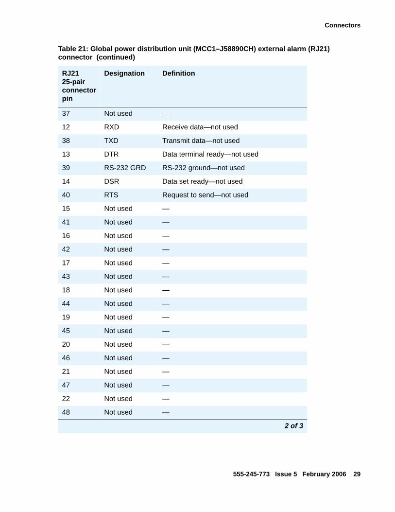
37 Not used —
12 RXD Receive data—not used
38 TXD Transmit data—not used
13 DTR Data terminal ready—not used
39 RS-232 GRD RS-232 ground—not used
14 DSR Data set ready—not used
40 RTS Request to send—not used
15 Not used —
41 Not used —
16 Not used —
42 Not used —
17 Not used —
43 Not used —
18 Not used —
44 Not used —
19 Not used —
45 Not used —
20 Not used —
46 Not used —
21 Not used —
47 Not used —
22 Not used —
48 Not used —
Table 21: Global power distribution unit (MCC1–J58890CH) external alarm (RJ21) connector (continued)
RJ21 25-pair connector pin
Designation Definition
2 of 3
Job Aid: Connector and Cable Diagrams (Pinout Charts)
30 Connector and Cable Diagrams (Pinout Charts)
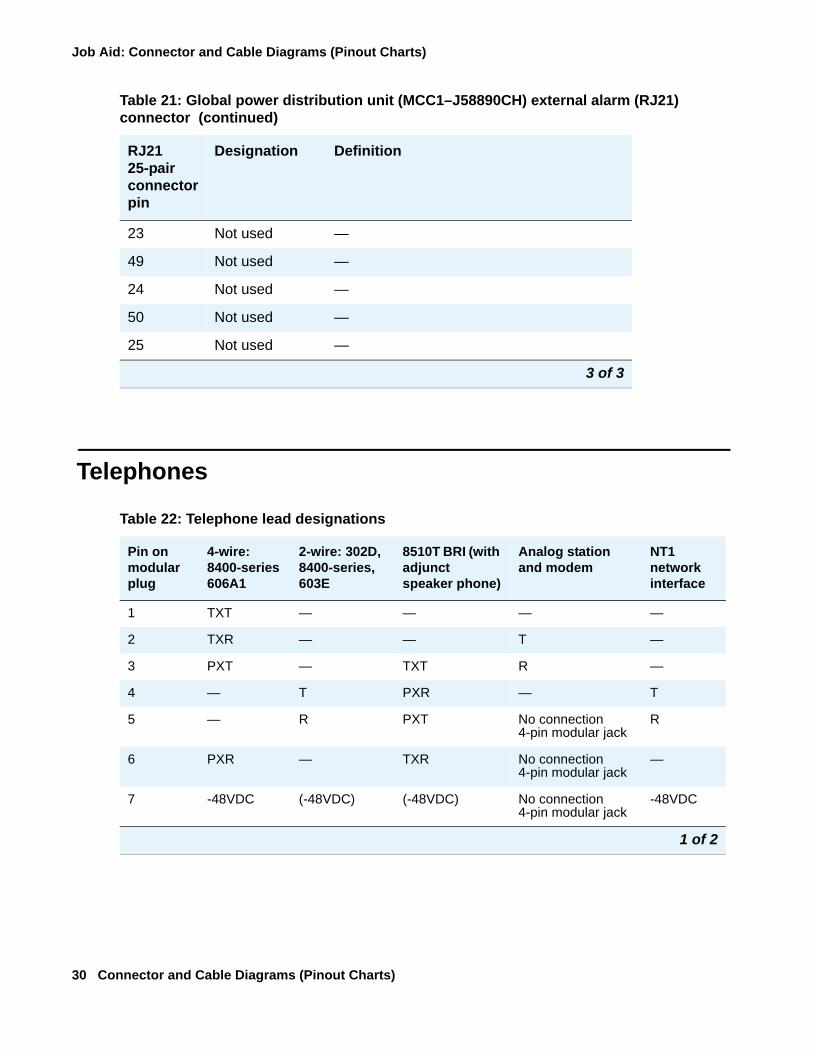
Telephones
23 Not used —
49 Not used —
24 Not used —
50 Not used —
25 Not used —
Table 21: Global power distribution unit (MCC1–J58890CH) external alarm (RJ21) connector (continued)
RJ21 25-pair connector pin
Designation Definition
3 of 3
Table 22: Telephone lead designations
Pin on modular plug
4-wire: 8400-series 606A1
2-wire: 302D, 8400-series, 603E
8510T BRI (with adjunct speaker phone)
Analog station and modem
NT1 network interface
1 TXT — — — —
2 TXR — — T —
3 PXT — TXT R —
4 — T PXR — T
5 — R PXT No connection 4-pin modular jack
R
6 PXR — TXR No connection 4-pin modular jack
—
7 -48VDC (-48VDC) (-48VDC) No connection 4-pin modular jack
-48VDC
1 of 2
Telephones
555-245-773 Issue 5 February 2006 31
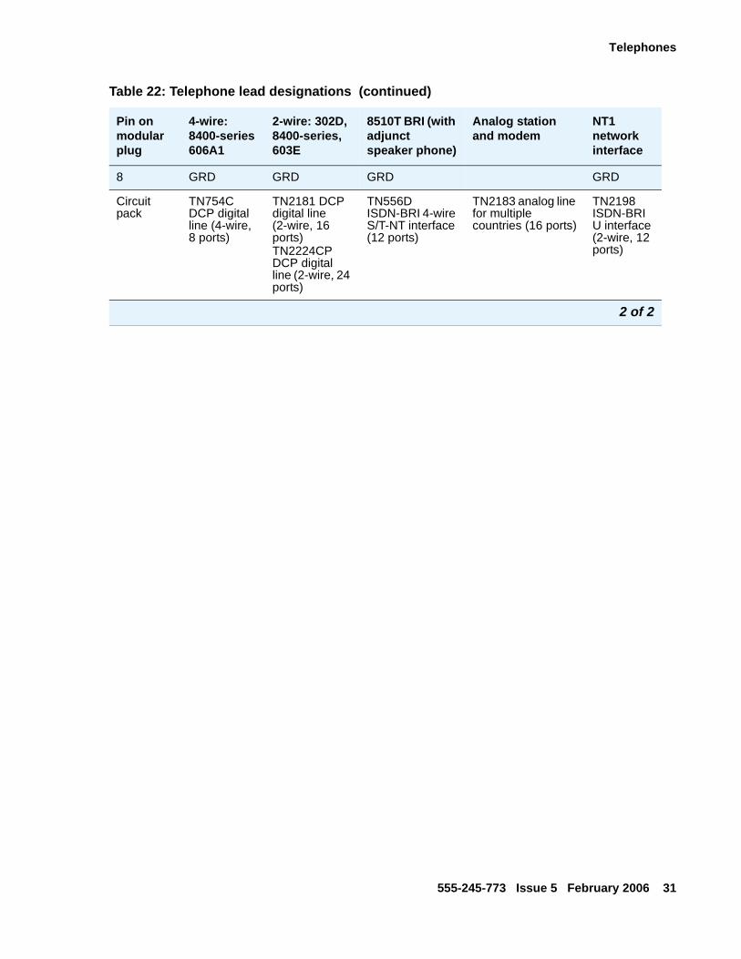
8 GRD GRD GRD GRD
Circuit pack
TN754C DCP digital line (4-wire, 8 ports)
TN2181 DCP digital line (2-wire, 16 ports) TN2224CP DCP digital line (2-wire, 24 ports)
TN556D ISDN-BRI 4-wire S/T-NT interface (12 ports)
TN2183 analog line for multiple countries (16 ports)
TN2198 ISDN-BRI U interface (2-wire, 12 ports)
Table 22: Telephone lead designations (continued)
Pin on modular plug
4-wire: 8400-series 606A1
2-wire: 302D, 8400-series, 603E
8510T BRI (with adjunct speaker phone)
Analog station and modem
NT1 network interface
2 of 2

Job Aid: Connector and Cable Diagrams (Pinout Charts)
32 Connector and Cable Diagrams (Pinout Charts)