Connection to the MV utility distribution network - …anduong.vn/uploadfile/data/file/Electrical...
38
Schneider Electric - Electrical installation guide 2007 B Chapter B Connection to the MV utility distribution network Contents Supply of power at medium voltage B2 1.1 Power supply characteristics of medium voltage B2 utility distribution network 1.2 Different MV service connections B11 1.3 Some operational aspects of MV distribution networks B12 Procedure for the establishment of a new substation B4 2.1 Preliminary informations B14 2.2 Project studies B15 2.3 Implementation B15 2.4 Commissioning B15 Protection aspect B6 3.1 Protection against electric shocks B16 3.2 Protection of transformer and circuits B17 3.3 Interlocks and conditioned operations B19 The consumer substation with LV metering B22 4.1 General B22 4.2 Choice of panels B22 4.3 Choice of MV switchgear panel for a transformer circuit B25 4.4 Choice of MV/LV transformer B25 The consumer substation with MV metering B30 5.1 General B30 5.2 Choice of panels B32 5.3 Parallel operation of transformers B33 Constitution of MV/LV distribution substations B35 6.1 Different types of substation B35 6.2 Indoor substation B35 6.3 Outdoor substation B37 2 3 4 5 6
Transcript of Connection to the MV utility distribution network - …anduong.vn/uploadfile/data/file/Electrical...
Schneider Electric - Electrical installation guide 2007
B�
Chapter BConnection to the MV utility distribution network
Contents Supply of power at medium voltage B2
1.1 Power supply characteristics of medium voltage B2 utility distribution network
1.2 Different MV service connections B11
1.3 Some operational aspects of MV distribution networks B12
Procedure for the establishment of a new substation B�4 2.1 Preliminary informations B14
2.2 Project studies B15
2.3 Implementation B15
2.4 Commissioning B15
Protection aspect B�6
3.1 Protection against electric shocks B16
3.2 Protection of transformer and circuits B17
3.3 Interlocks and conditioned operations B19
The consumer substation with LV metering B22
4.1 General B22
4.2 Choice of panels B22
4.3 Choice of MV switchgear panel for a transformer circuit B25
4.4 Choice of MV/LV transformer B25
The consumer substation with MV metering B30
5.1 General B30
5.2 Choice of panels B32
5.3 Parallel operation of transformers B33
Constitution of MV/LV distribution substations B35
6.1 Different types of substation B35
6.2 Indoor substation B35
6.3 Outdoor substation B37
2
�
3
4
5
6

Schneider Electric - Electrical installation guide 2007
B - Connection to the MV public distribution network
B2At present there is no international agreement on precise limits to define “medium” voltage.
Voltage levels which are designated as “medium” in some countries are referred to as “medium” in others.
In this chapter, distribution networks which operate at voltages of 1,000 V or less are referred to as Low-Voltage systems, while systems of power distribution which require one stage of stepdown voltage transformation, in order to feed into low voltage networks, will be referred to as Medium- Voltage systems.
For economic and technical reasons the nominal voltage of medium-voltage distribution systems, as defined above, seldom exceeds 35 kV.
�.� Power supply characteristics of medium voltage utility distribution network
Nominal voltage and related insulation levelsThe nominal voltage of a system or of an equipment is defined in IEC 60038 as “the voltage by which a system or equipment is designated and to which certain operating characteristics are referred”. Closely related to the nominal voltage is the “highest voltage for equipment” which concerns the level of insulation at normal working frequency, and to which other characteristics may be referred in relevant equipment recommendations.
The “highest voltage for equipment” is defined in IEC 60038 as:“the maximum value of voltage for which equipment may be used, that occurs under normal operating conditions at any time and at any point on the system. It excludes voltage transients, such as those due to system switching, and temporary voltage variations”.
Notes:�- The highest voltage for equipment is indicated for nominal system voltages higher than 1,000 V only. It is understood that, particularly for certain nominal system voltages, normal operation of equipment cannot be ensured up to this highest voltage for equipment, having regard to voltage sensitive characteristics such as losses of capacitors, magnetizing current of transformers, etc. In such cases, IEC standards specify the limit to which the normal operation of this equipment can be ensured.2- It is understood that the equipment to be used in systems having nominal voltage not exceeding 1,000 V should be specified with reference to the nominal system voltage only, both for operation and for insulation.3- The definition for “highest voltage for equipment” given in IEC 60038 is identical to the definition given in IEC 60694 for “rated voltage”. IEC 60694 concerns switchgear for voltages exceeding 1,000 V.
The following values of Figure B�, taken from IEC 60038, list the most-commonly used standard levels of medium-voltage distribution, and relate the nominal voltages to corresponding standard values of “Highest Voltage for Equipment”.
These systems are generally three-wire systems unless otherwise indicated. The values shown are voltages between phases.
The values indicated in parentheses should be considered as non-preferred values. It is recommended that these values should not be used for new systems to be constructed in future.
� Supply of power at medium voltage
The main features which characterize a power-supply system include:b The nominal voltage and related insulation levelsb The short-circuit currentb The rated normal current of items of plant and equipmentb The earthing system
Fig. B1 : Relation between nominal system voltages and highest voltages for the equipment
Series I (for 50 Hz and 60 Hz networks)Nominal system voltage Highest voltage for equipement(kV) (kV)3.3 (1) 3 (1) 3.6 (1) 6.6 (1) 6 (1) 7.2 (1) 11 10 12 - 15 17.5 22 20 24 33 (2) - 36 (2) - 35 (2) 40.5 (2) (1) These values should not be used for public distribution systems.(2) The unification of these values is under consideration.

Schneider Electric - Electrical installation guide 2007
B - Connection to the MV public distribution network
B3It is recommended that in any one country the ratio between two adjacent nominal voltages should be not less than two.
In order to ensure adequate protection of equipment against abnormally-medium short term power-frequency overvoltages, and transient overvoltages caused by lightning, switching, and system fault conditions, etc. all MV equipment must be specified to have appropriate Rated Insulation Levels.
SwitchgearFigure B2 shown below, is extracted from IEC 60694 and lists standard values of “withstand” voltage requirements. The choice between List 1 and List 2 values of table B2 depends on the degree of exposure to lightning and switching overvoltages(1), the type of neutral earthing, and the type of overvoltage protection devices, etc. (for further guidance reference should be made to IEC 60071).
(1) This means basically that List 1 generally applies to switchgear to be used on underground-cable systems while List 2 is chosen for switchgear to be used on overhead-line systems.
Rated Rated lightning impulse withstand voltage Rated short-duration voltage (peak value) power-frequency U (r.m.s. withstand voltage value) List � List 2 (r.m.s. value)
To earth, Across the To earth, Across the To earth, Across the between isolating between isolating between isolating poles distance poles distance poles distance and across and across and across open open open switching switching switching device device device (kV) (kV) (kV) (kV) (kV) (kV) (kV)3.6 20 23 40 46 10 127.2 40 46 60 70 20 2312 60 70 75 85 28 3217.5 75 85 95 110 38 4524 95 110 125 145 50 6036 145 165 170 195 70 8052 - - 250 290 95 11072.5 - - 325 375 140 160Note: The withstand voltage values “across the isolating distance” are valid only for the switching devices where the clearance between open contacts is designed to meet safety requirements specified for disconnectors (isolators).
Fig. B2 : Switchgear rated insulation levels
It should be noted that, at the voltage levels in question, no switching overvoltage ratings are mentioned. This is because overvoltages due to switching transients are less severe at these voltage levels than those due to lightning.
TransformersFigure B3 shown below have been extracted from IEC 60076-3.
The significance of list 1 and list 2 is the same as that for the switchgear table, i.e. the choice depends on the degree of exposure to lightning, etc.
Fig. B3 : Transformers rated insulation levels
Highest voltage Rated short duration Rated lightning impulse for equipment power frequency withstand voltage (r.m.s.) withstand voltage (peak) (r.m.s.) List � List 2 (kV) (kV) (kV) (kV)y 1.1 3 - -3.6 10 20 407.2 20 40 6012 28 60 7517.5 38 75 9524 50 95 12536 70 145 17052 95 25072.5 140 325
� Supply of power at medium voltage

Schneider Electric - Electrical installation guide 2007
B - Connection to the MV public distribution network
B4Other componentsIt is evident that the insulation performance of other MV components associated with these major items, e.g. porcelain or glass insulators, MV cables, instrument transformers, etc. must be compatible with that of the switchgear and transformers noted above. Test schedules for these items are given in appropriate IEC publications.
The national standards of any particular country are normally rationalized to include one or two levels only of voltage, current, and fault-levels, etc.
General note:The IEC standards are intended for worldwide application and consequently embrace an extensive range of voltage and current levels.These reflect the diverse practices adopted in countries of different meteorologic, geographic and economic constraints.
Short-circuit currentStandard values of circuit-breaker short-circuit current-breaking capability are normally given in kilo-amps.
These values refer to a 3-phase short-circuit condition, and are expressed as the average of the r.m.s. values of the AC component of current in each of the three phases.
For circuit-breakers in the rated voltage ranges being considered in this chapter, Figure B4 gives standard short-circuit current-breaking ratings.
The national standards of any particular country are normally rationalized to include one or two levels only of voltage, current, and fault-levels, etc.
A circuit-breaker (or fuse switch, over a limited voltage range) is the only form of switchgear capable of safely breaking the very medium levels of current associated with short-circuit faults occurring on a power system.
Fig. B4 : Standard short-circuit current-breaking ratings
tmin
Current (I)
IDC
Ip
Time (t)
22I''k
22Ik
22Ib
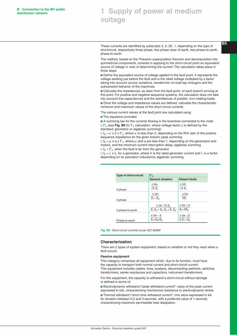
Fig. B5 : Graphic representation of short-circuit quantities as per IEC 60909
kV 3.6 7.2 �2 �7.5 24 36 52kA 8 8 8 8 8 8 8(rms) 10 12.5 12.5 12.5 12.5 12.5 12.5 16 16 16 16 16 16 20 25 25 25 25 25 25 40 40 40 40 40 40 50
Short-circuit current calculationThe rules for calculating short-circuit currents in electrical installations are presented in IEC standard 60909.The calculation of short-circuit currents at various points in a power system can quickly turn into an arduous task when the installation is complicated.The use of specialized software accelerates calculations.This general standard, applicable for all radial and meshed power systems, 50 or 60 Hz and up to 550 kV, is extremely accurate and conservative.
It may be used to handle the different types of solid short-circuit (symmetrical or dissymmetrical) that can occur in an electrical installation:b Three-phase short-circuit (all three phases), generally the type producing the highest currentsb Two-phase short-circuit (between two phases), currents lower than three-phase faultsb Two-phase-to-earth short-circuit (between two phases and earth)b Phase-to-earth short-circuit (between a phase and earth), the most frequent type (80% of all cases).
When a fault occurs, the transient short-circuit current is a function of time and comprises two components (see Fig. B5).b An AC component, decreasing to its steady-state value, caused by the various rotating machines and a function of the combination of their time constantsb A DC component, decreasing to zero, caused by the initiation of the current and a function of the circuit impedances
Practically speaking, one must define the short-circuit values that are useful in selecting system equipment and the protection system:b I’’k: rms value of the initial symmetrical currentb Ib: rms value of the symmetrical current interrupted by the switching device when the first pole opens at tmin (minimum delay)b Ik: rms value of the steady-state symmetrical currentb Ip: maximum instantaneous value of the current at the first peakb IDC: DC value of the current
� Supply of power at medium voltage
Schneider Electric - Electrical installation guide 2007
B - Connection to the MV public distribution network
B5
� Supply of power at medium voltage
These currents are identified by subscripts 3, 2, 2E, 1, depending on the type of shortcircuit, respectively three-phase, two-phase clear of earth, two-phase-to-earth, phase-to-earth.
The method, based on the Thevenin superposition theorem and decomposition into symmetrical components, consists in applying to the short-circuit point an equivalent source of voltage in view of determining the current. The calculation takes place in three steps.b Define the equivalent source of voltage applied to the fault point. It represents the voltage existing just before the fault and is the rated voltage multiplied by a factor taking into account source variations, transformer on-load tap changers and the subtransient behavior of the machines.b Calculate the impedances, as seen from the fault point, of each branch arriving at this point. For positive and negative-sequence systems, the calculation does not take into account line capacitances and the admittances of parallel, non-rotating loads.b Once the voltage and impedance values are defined, calculate the characteristic minimum and maximum values of the short-circuit currents.
The various current values at the fault point are calculated using:b The equations providedb A summing law for the currents flowing in the branches connected to the node:v I’’k (see Fig. B6 for I’’k calculation, where voltage factor c is defined by the standard; geometric or algebraic summing)v Ip = κ x 2 x I’’k, where κ is less than 2, depending on the R/X ratio of the positive sequence impedance for the given branch; peak summingv Ib = μ x q x I’’k, where μ and q are less than 1, depending on the generators and motors, and the minimum current interruption delay; algebraic summingv Ik = I’’k, when the fault is far from the generatorv Ik = λ x Ir, for a generator, where Ir is the rated generator current and λ is a factor depending on its saturation inductance; algebraic summing.
Fig. B6 : Short-circuit currents as per IEC 60909
Type of short-circuit I’’k General situation Distant faults
3-phase
c Un
Z13
c Un
Z13
2-phase
c UnZ Z1 2+
c Un
12Z
2-phase-to-earth
c UnZ Z Z Z Z Z
3 Z
2
1 2 2 0 1 0+ +
c Un 3
1+Z 2Z0
Phase-to-earth 0 1 0+ +
c UnZ
3 1+Z +Z02
c UnZ Z 3
1 02 +
CharacterizationThere are 2 types of system equipment, based on whether or not they react when a fault occurs.
Passive equipmentThis category comprises all equipment which, due to its function, must havethe capacity to transport both normal current and short-circuit current.This equipment includes cables, lines, busbars, disconnecting switches, switches, transformers, series reactances and capacitors, instrument transformers.
For this equipment, the capacity to withstand a short-circuit without damageis defined in terms of:
b Electrodynamic withstand (“peak withstand current”; value of the peak current expressed in kA), characterizing mechanical resistance to electrodynamic stress
b Thermal withstand (“short time withstand current”; rms value expressed in kA for duration between 0,5 and 3 seconds, with a preferred value of 1 second), characterizing maximum permissible heat dissipation.

Schneider Electric - Electrical installation guide 2007
B - Connection to the MV public distribution network
B6Active equipmentThis category comprises the equipment designed to clear short-circuit currents, i.e. circuit-breakers and fuses. This property is expressed by the breaking capacity and, if required, the making capacity when a fault occurs.
b Breaking capacity (see Fig. B7)This basic characteristic of a fault interrupting device is the maximum current (rms value expressed in kA) it is capable of breaking under the specific conditions defined by the standards; in the IEC 60056 standard, it refers to the rms value of the AC component of the short-circuit current. In some other standards, the rms value of the sum of the 2 components (AC and DC) is specified, in which case, it is the “asymmetrical current”.The breaking capacity depends on other factors such as:v Voltagev R/X ratio of the interrupted circuitv Power system natural frequencyv Number of breaking operations at maximum current, for example the cycle: O - C/O - C/O (O = opening, C = closing)v Device status after the testThe breaking capacity is a relatively complicated characteristic to define and ittherefore comes as no surprise that the same device can be assigned different breaking capacities depending on the standard by which it is defined.
b Short-circuit making capacityIn general, this characteristic is implicitly defined by the breaking capacity because a device should be able to close for a current that it can break.Sometimes, the making capacity needs to be higher, for example for circuit-breakers protecting generators.The making capacity is defined in terms of peak value (expressed in kA) because the first asymmetric peak is the most demanding from an electrodynamic point of view.For example, according to standard IEC 62271-100, a circuit-breaker used in a 50 Hz power system must be able to handle a peak making current equal to 2.5 times the rms breaking current (2.6 times for 60 Hz systems).Making capacity is also required for switches, and sometimes for disconnectors, even if these devices are not able to clear the fault.
b Prospective short-circuit breaking currentSome devices have the capacity to limit the fault current to be interrupted.Their breaking capacity is defined as the maximum prospective breaking current that would develop during a solid short-circuit across the upstream terminals of the device.
Specific device characteristicsThe functions provided by various interrupting devices and their main constraints are presented in Figure B8.
Current (I)
IAC
IAC: Peak of the periodic componentIDC: Aperiodic component
IDC
Time (t)
Fig. B7 : Rated breaking current of a circuit-breaker subjected to a short-circuit as per IEC 60056 Fig. B8 : Functions provided by interrupting devices
Device Isolation of Current switching Main constrains two active conditions networks Normal Fault Disconnector Yes No No Longitudinal input/output isolationSwitch No Yes No Making and breaking of normal load current Short-circuit making capacityContactor No Yes No Rated making and breaking capacities Maximum making and breaking capacities Duty and endurance characteristics Circuit-breaker No Yes Yes Short-circuit breaking capacity Short-circuit making capacity
Fuse No No Yes Minimum short-circuit breaking capacity Maximum short-circuit breaking capacity
� Supply of power at medium voltage
Schneider Electric - Electrical installation guide 2007
B - Connection to the MV public distribution network
B7
� Supply of power at medium voltage
Rated normal currentThe rated normal current is defined as “the r.m.s. value of the current which can be carried continuously at rated frequency with a temperature rise not exceeding that specified by the relevant product standard”.
The rated normal current requirements for switchgear are decided at the substation design stage.
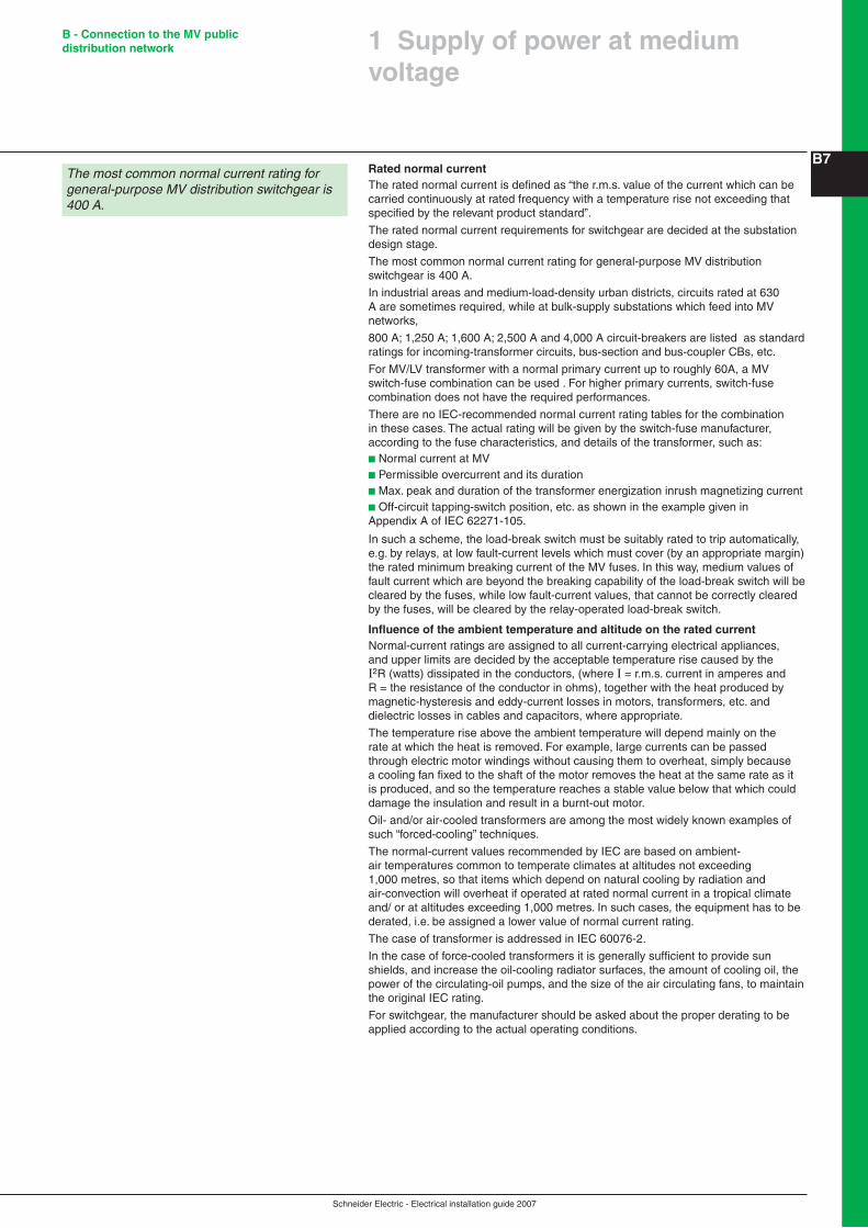
The most common normal current rating for general-purpose MV distribution switchgear is 400 A.
In industrial areas and medium-load-density urban districts, circuits rated at 630 A are sometimes required, while at bulk-supply substations which feed into MV networks,
800 A; 1,250 A; 1,600 A; 2,500 A and 4,000 A circuit-breakers are listed as standard ratings for incoming-transformer circuits, bus-section and bus-coupler CBs, etc.
For MV/LV transformer with a normal primary current up to roughly 60A, a MV switch-fuse combination can be used . For higher primary currents, switch-fuse combination does not have the required performances.
There are no IEC-recommended normal current rating tables for the combination in these cases. The actual rating will be given by the switch-fuse manufacturer, according to the fuse characteristics, and details of the transformer, such as:b Normal current at MVb Permissible overcurrent and its durationb Max. peak and duration of the transformer energization inrush magnetizing currentb Off-circuit tapping-switch position, etc. as shown in the example given in Appendix A of IEC 62271-105.
In such a scheme, the load-break switch must be suitably rated to trip automatically, e.g. by relays, at low fault-current levels which must cover (by an appropriate margin) the rated minimum breaking current of the MV fuses. In this way, medium values of fault current which are beyond the breaking capability of the load-break switch will be cleared by the fuses, while low fault-current values, that cannot be correctly cleared by the fuses, will be cleared by the relay-operated load-break switch.
Influence of the ambient temperature and altitude on the rated currentNormal-current ratings are assigned to all current-carrying electrical appliances, and upper limits are decided by the acceptable temperature rise caused by the I2R (watts) dissipated in the conductors, (where I = r.m.s. current in amperes and R = the resistance of the conductor in ohms), together with the heat produced by magnetic-hysteresis and eddy-current losses in motors, transformers, etc. and dielectric losses in cables and capacitors, where appropriate.
The temperature rise above the ambient temperature will depend mainly on the rate at which the heat is removed. For example, large currents can be passed through electric motor windings without causing them to overheat, simply because a cooling fan fixed to the shaft of the motor removes the heat at the same rate as it is produced, and so the temperature reaches a stable value below that which could damage the insulation and result in a burnt-out motor.
Oil- and/or air-cooled transformers are among the most widely known examples of such “forced-cooling” techniques.
The normal-current values recommended by IEC are based on ambient-air temperatures common to temperate climates at altitudes not exceeding 1,000 metres, so that items which depend on natural cooling by radiation and air-convection will overheat if operated at rated normal current in a tropical climate and/ or at altitudes exceeding 1,000 metres. In such cases, the equipment has to be derated, i.e. be assigned a lower value of normal current rating.
The case of transformer is addressed in IEC 60076-2.
In the case of force-cooled transformers it is generally sufficient to provide sun shields, and increase the oil-cooling radiator surfaces, the amount of cooling oil, the power of the circulating-oil pumps, and the size of the air circulating fans, to maintain the original IEC rating.
For switchgear, the manufacturer should be asked about the proper derating to be applied according to the actual operating conditions.
The most common normal current rating for general-purpose MV distribution switchgear is 400 A.

Schneider Electric - Electrical installation guide 2007
B - Connection to the MV public distribution network
B8Earthing systemsEarthing and equipment-bonding earth connections require careful consideration, particularly regarding safety of the LV consumer during the occurrence of a short-circuit to earth on the MV system.
Earth electrodesIn general, it is preferable, where physically possible, to separate the electrode provided for earthing exposed conductive parts of MV equipment from the electrode intended for earthing the LV neutral conductor. This is commonly practised in rural systems where the LV neutral-conductor earth electrode is installed at one or two spans of LV distribution line away from the substation.
In most cases, the limited space available in urban substations precludes this practice, i.e. there is no possibility of separating a MV electrode sufficiently from a LV electrode to avoid the transference of (possibly dangerous) voltages to the LV system.
Earth-fault currentEarth-fault current levels at medium voltage are generally (unless deliberately restricted) comparable to those of a 3-phase shortcircuit.
Such currents passing through an earth electrode will raise its voltage to a medium value with respect to “remote earth” (the earth surrounding the electrode will be raised to a medium potential; “remote earth” is at zero potential).
For example, 10,000 A of earth-fault current passing through an electrode with an (unusually low) resistance of 0.5 ohms will raise its voltage to 5,000 V.
Providing that all exposed metal in the substation is “bonded” (connected together) and then connected to the earth electrode, and the electrode is in the form of (or is connected to) a grid of conductors under the floor of the substation, then there is no danger to personnel, since this arrangement forms an equipotential “cage” in which all conductive material, including personnel, is raised to the same potential.
Transferred potentialA danger exists however from the problem known as Transferred Potential. It will be seen in Figure B9 that the neutral point of the LV winding of the MV/LV transformer is also connected to the common substation earth electrode, so that the neutral conductor, the LV phase windings and all phase conductors are also raised to the electrode potential.
Low-voltage distribution cables leaving the substation will transfer this potential to consumers installations. It may be noted that there will be no LV insulation failure between phases or from phase to neutral since they are all at the same potential. It is probable, however, that the insulation between phase and earth of a cable or some part of an installation would fail.
SolutionsA first step in minimizing the obvious dangers of transferred potentials is to reduce the magnitude of MV earth-fault currents. This is commonly achieved by earthing the MV system through resistors or reactors at the star points of selected transformers(1), located at bulk-supply substations.
A relatively medium transferred potential cannot be entirely avoided by this means, however, and so the following strategy has been adopted in some countries.
The equipotential earthing installation at a consumer’s premises represents a remote earth, i.e. at zero potential. However, if this earthing installation were to be connected by a low-impedance conductor to the earth electrode at the substation, then the equipotential conditions existing in the substation would also exist at the consumer’s installation.
Low-impedance interconnectionThis low-impedance interconnection is achieved simply by connecting the neutral conductor to the consumer’s equipotential installation, and the result is recognized as the TN earthing system (IEC 60364) as shown in diagram A of Figure B�0 next page.
The TN system is generally associated with a Protective Multiple Earthing (PME) scheme, in which the neutral conductor is earthed at intervals along its length (every 3rd or 4th pole on a LV overhead-line distributor) and at each consumer’s service position. It can be seen that the network of neutral conductors radiating from a substation, each of which is earthed at regular intervals, constitutes, together with the substation earthing, a very effective low-resistance earth electrode.
(1) The others being unearthed. A particular case of earth-fault current limitation is by means of a Petersen coil.
Earth faults on medium-voltage systems can produce dangerous voltage levels on LV installations. LV consumers (and substation operating personnel) can be safeguarded against this danger by:b Restricting the magnitude of MV earth-fault currentsb Reducing the substation earthing resistance to the lowest possible valueb Creating equipotential conditions at the substation and at the consumer’s installation
N
3
2
1
Fault
HV LV
If
If
V= IfRs
Consumer
Rs
Fig. B9 : Transferred potential
� Supply of power at medium voltage

Schneider Electric - Electrical installation guide 2007
B - Connection to the MV public distribution network
B9
� Supply of power at medium voltage
The combination of restricted earth-fault currents, equipotential installations and low resistance substation earthing, results in greatly reduced levels of overvoltage and limited stressing of phase-to-earth insulation during the type of MV earth-fault situation described above.
Limitation of the MV earth-fault current and earth resistance of the substationAnother widely-used earthing system is shown in diagram C of Figure B10. It will be seen that in the TT system, the consumer’s earthing installation (being isolated from that of the substation) constitutes a remote earth.
This means that, although the transferred potential will not stress the phase-to-phase insulation of the consumer’s equipment, the phase-to-earth insulation of all three phases will be subjected to overvoltage.
Fig. B10 : Maximum earthing resistance Rs at a MV/LV substation to ensure safety during a short-circuit to earth fault on the medium-voltage equipment for different earthing systems
N
3
2
1
Diagram Rs value
N
3
2
1MV LVMV LV
MV LVMV LV
MV LVMV LV
RSRS
Cases A and B
No particular resistance value for Rs is imposed in these cases
Cases C and D
WhereUw = the rated normal-frequency withstand voltage for low-voltage equipment at consumer installationsUo = phase to neutral voltage at consumer's installationsIm = maximum value of MV earth-fault current
WhereUws = the normal-frequency withstand voltage for low-voltage equipments in the substation (since the exposed conductive parts of these equipments are earthed via Rs)U = phase to neutral voltage at the substation for the TT(s) system, but the phase-to- phase voltage for the IT(s) systemIm = maximum value of MV earth-fault current
Rs y Uw - Uo Im
N
3
2
1
RS
N
3
2
1
RS
N
3
2
1
RNRS
N
3
2
1
RNRS
In cases E and F the LV protective conductors (bonding exposed conductive parts) in the substationare earthed via the substation earth electrode, and it is therefore the substation LV equipment (only) that could be subjected to overvoltage.
Cases E and F
Rs y Uws - U Im
B - IT-aA - TN-a
D - IT-bC - TT-a
F - IT-cE - TT-b
Notes:b For TN-a and IT-a, the MV and LV exposed conductive parts at the substation and those at the consumer’s installations, together with the LV neutral point of the transformer, are all earthed via the substation electrode system.b For TT-a and IT-b, the MV and LV exposed conductive parts at the substation, together with the LV neutral point of the transformer are earthed via the substation electrode system.b For TT-b and IT-c, the LV neutral point of the transformer is separately earthed outside of the area of influence of the substation earth electrode.Uw and Uws are commonly given the (IEC 60364-4-44) value Uo + 1200 V, where Uo is the nominal phase-to-neutral voltage of the LV system concerned.

Schneider Electric - Electrical installation guide 2007
B - Connection to the MV public distribution network
B�0The strategy in this case, is to reduce the resistance of the substation earth electrode, such that the standard value of 5-second withstand-voltage-to-earth for LV equipment and appliances will not be exceeded.
Practical values adopted by one national electrical power-supply authority, on its 20 kV distribution systems, are as follows:b Maximum earth-fault current in the neutral connection on overheadline distribution systems, or mixed (O/H line and U/G cable) systems, is 300 Ab Maximum earth-fault current in the neutral connection on underground systems is 1,000 A
The formula required to determine the maximum value of earthing resistance Rs at the substation, to ensure that the LV withstand voltage will not be exceeded, is:the substation, to ensure that the LV withstand voltage will not be exceeded, is:
RsUw Uo
=Im
in ohms (see cases C and D in Figure C10).
Where
in ohms (see cases C and D in Figure B10).
Where
Uw = the lowest standard value (in volts) of short-term (5 s) withstand voltage for the consumer’s installation and appliances = Uo + 1200 V (IEC 60364-4-44)
Uo = phase to neutral voltage (in volts) at the consumer’s LV service position
Im = maximum earth-fault current on the MV system (in amps). This maximum earth fault current Im is the vectorial sum of maximum earth-fault current in the neutral connection and total unbalanced capacitive current of the network.
A third form of system earthing referred to as the “IT” system in IEC 60364 is commonly used where continuity of supply is essential, e.g. in hospitals, continuous-process manufacturing, etc. The principle depends on taking a supply from an unearthed source, usually a transformer, the secondary winding of which is unearthed, or earthed through a medium impedance (u1,000 ohms). In these cases, an insulation failure to earth in the low-voltage circuits supplied from the secondary windings will result in zero or negligible fault-current flow, which can be allowed to persist until it is convenient to shut-down the affected circuit to carry out repair work.
Diagrams B, D and F (Figure B10) They show IT systems in which resistors (of approximately 1,000 ohms) are included in the neutral earthing lead.If however, these resistors were removed, so that the system is unearthed, the following notes apply.
Diagram B (Figure B10)All phase wires and the neutral conductor are “floating” with respect to earth, to which they are “connected” via the (normally very medium) insulation resistances and (very small) capacitances between the live conductors and earthed metal (conduits, etc.).
Assuming perfect insulation, all LV phase and neutral conductors will be raised by electrostatic induction to a potential approaching that of the equipotential conductors.
In practice, it is more likely, because of the numerous earth-leakage paths of all live conductors in a number of installations acting in parallel, that the system will behave similarly to the case where a neutral earthing resistor is present, i.e. all conductors will be raised to the potential of the substation earth.
In these cases, the overvoltage stresses on the LV insulation are small or non-existent.
Diagrams D and F (Figure B10)In these cases, the medium potential of the substation (S/S) earthing system acts on the isolated LV phase and neutral conductors:b Through the capacitance between the LV windings of the transformer and the transformer tankb Through capacitance between the equipotential conductors in the S/S and the cores of LV distribution cables leaving the S/Sb Through current leakage paths in the insulation, in each case.
At positions outside the area of influence of the S/S earthing, system capacitances exist between the conductors and earth at zero potential (capacitances between cores are irrelevant - all cores being raised to the same potential).
The result is essentially a capacitive voltage divider, where each “capacitor” is shunted by (leakage path) resistances.
In general, LV cable and installation wiring capacitances to earth are much larger, and the insulation resistances to earth are much smaller than those of the corresponding parameters at the S/S, so that most of the voltage stresses appear at the substation between the transformer tank and the LV winding.
The rise in potential at consumers’ installations is not likely therefore to be a problem where the MV earth-fault current level is restricted as previously mentioned.
� Supply of power at medium voltage
Schneider Electric - Electrical installation guide 2007
B - Connection to the MV public distribution network
B��
� Supply of power at medium voltage
All IT-earthed transformers, whether the neutral point is isolated or earthed through a medium impedance, are routinely provided with an overvoltage limiting device which will automatically connect the neutral point directly to earth if an overvoltage condition approaches the insulation-withstand level of the LV system.
In addition to the possibilities mentioned above, several other ways in which these overvoltages can occur are described in Clause 3.1.
This kind of earth-fault is very rare, and when does occur is quickly detected and cleared by the automatic tripping of a circuit-breaker in a properly designed and constructed installation.
Safety in situations of elevated potentials depends entirely on the provision of properly arranged equipotential areas, the basis of which is generally in the form of a widemeshed grid of interconnected bare copper conductors connected to vertically-driven copper-clad(1) steel rods.
The equipotential criterion to be respected is that which is mentioned in Chapter F dealing with protection against electric shock by indirect contact, namely: that the potential between any two exposed metal parts which can be touched simultaneously by any parts the body must never, under any circumstances, exceed 50 V in dry conditions, or 25 V in wet conditions.
Special care should be taken at the boundaries of equipotential areas to avoid steep potential gradients on the surface of the ground which give rise to dangerous “step potentials”.
This question is closely related to the safe earthing of boundary fences and is further discussed in Sub-clause 3.1.
�.2 Different MV service connections
According to the type of medium-voltage network, the following supply arrangements are commonly adopted.
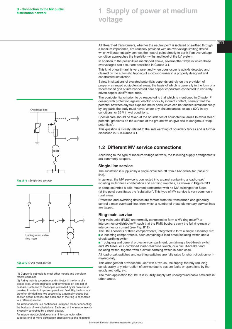
Single-line serviceThe substation is supplied by a single circuit tee-off from a MV distributor (cable or line).
In general, the MV service is connected into a panel containing a load-break/isolating switch-fuse combination and earthing switches, as shown in Figure B��.
In some countries a pole-mounted transformer with no MV switchgear or fuses (at the pole) constitutes the “substation”. This type of MV service is very common in rural areas.
Protection and switching devices are remote from the transformer, and generally control a main overhead-line, from which a number of these elementary service lines are tapped.
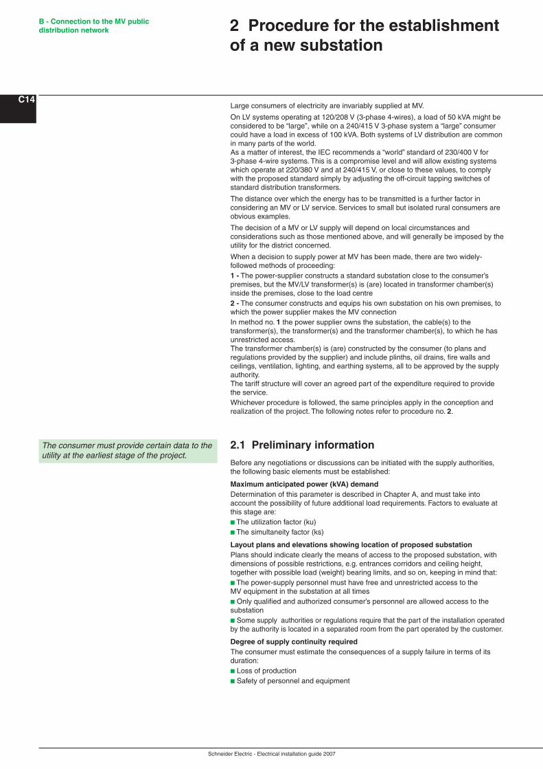
Ring-main serviceRing-main units (RMU) are normally connected to form a MV ring main(2) or interconnector-distributor(2), such that the RMU busbars carry the full ring-main or interconnector current (see Fig. B�2).The RMU consists of three compartments, integrated to form a single assembly, viz:b 2 incoming compartments, each containing a load break/isolating switch and a circuit earthing switchb 1 outgoing and general protection compartment, containing a load-break switch and MV fuses, or a combined load-break/fuse switch, or a circuit-breaker and isolating switch, together with a circuit-earthing switch in each case.
All load-break switches and earthing switches are fully rated for short-circuit current-making duty.
This arrangement provides the user with a two-source supply, thereby reducing considerably any interruption of service due to system faults or operations by the supply authority, etc.
The main application for RMUs is in utility supply MV underground-cable networks in urban areas.
(1) Copper is cathodic to most other metals and therefore resists corrosion.(2) A ring main is a continuous distributor in the form of a closed loop, which originates and terminates on one set of busbars. Each end of the loop is controlled by its own circuit-breaker. In order to improve operational flexibility the busbars are often divided into two sections by a normally closed bus-section circuit-breaker, and each end of the ring is connected to a different section.An interconnector is a continuous untapped feeder connecting the busbars of two substations. Each end of the interconnector is usually controlled by a circuit beaker.An interconnector-distributor is an interconnector which supplies one or more distribution substations along its length.
Overhead line
Fig. B11 : Single-line service
Fig. B12 : Ring-main service
Underground cablering main

Schneider Electric - Electrical installation guide 2007
B - Connection to the MV public distribution network
B�2
Fig. B13 : Parallel feeders service
Parallel feeders serviceWhere a MV supply connection to two lines or cables originating from the same busbar of a substation is possible, a similar MV switchboard to that of a RMU is commonly used (see Fig. B�3).
The main operational difference between this arrangement and that of a RMU is that the two incoming panels are mutually interlocked, such that one incoming switch only can be closed at a time, i.e. its closure prevents the closure of the other.
On the loss of power supply, the closed incoming switch must be opened and the (formerly open) switch can then be closed.
The sequence may be carried out manually or automatically.
This type of switchboard is used particularly in networks of medium-load density and in rapidly-expanding urban areas supplied by MV underground cable systems.
�.3 Some operational aspects of MV distribution networks
Overhead linesMedium winds, ice formation, etc., can cause the conductors of overhead lines to touch each other, thereby causing a momentary (i.e. not permanent) short-circuit fault.Insulation failure due to broken ceramic or glass insulators, caused by air-borne debris; careless use of shot-guns, etc., or again, heavily polluted insulator surfaces, can result in a short-circuit to earth.
Many of these faults are self-clearing. For example, in dry conditions, broken insulators can very often remain in service undetected, but are likely to flashover to earth (e.g. to a metal supporting structure) during a rainstorm. Moreover, polluted surfaces generally cause a flashover to earth only in damp conditions.
The passage of fault current almost invariably takes the form of an electric arc, the intense heat of which dries the current path, and to some extent, re-establishes its insulating properties. In the meantime, protective devices have usually operated to clear the fault, i.e. fuses have blown or a circuit-breaker has tripped.
Experience has shown that in the large majority of cases, restoration of supply by replacing fuses or by re-closing a circuit-breaker will be successful.
For this reason it has been possible to considerably improve the continuity of service on MV overhead-line distribution networks by the application of automatic circuit-breaker reclosing schemes at the origin of the circuits concerned.
These automatic schemes permit a number of reclosing operations if a first attempt fails, with adjustable time delays between successive attempts (to allow de-ionization of the air at the fault) before a final lock-out of the circuit-breaker occurs, after all (generally three) attempts fail.
Other improvements in service continuity are achieved by the use of remotely-controlled section switches and by automatic isolating switches which operate in conjunction with an auto-reclosing circuit-breaker.
This last scheme is exemplified by the final sequence shown in Figure B�4 next page.
The principle is as follows: If, after two reclosing attempts, the circuit-breaker trips, the fault is assumed to be permanent, and, while the feeder is dead, the Automatic Line Switch opens to isolate a section of the network, before the third (and final) reclosure takes place.
There are then two possibilities:b The fault is on the section which is isolated by the Automatic Line Switch, and supply is restored to those consumers connected to the remaining section, orb The fault is on the section upstream of the Automatic Line Switch and the circuit-breaker will trip and lock out.The Automatic Line Switch scheme, therefore, provides the possibility of restoration of supplies to some consumers in the event of a permanent fault.
While these measures have greatly improved the reliability of supplies from MV overhead line systems, the consumers must, where considered necessary, make their own arrangements to counter the effects of momentary interruptions to supply (between reclosures), for example:b Uninterruptible standby emergency powerb Lighting that requires no cooling down before re-striking (“hot restrike”).
Paralleled undergroundcable distributors
� Supply of power at medium voltage

Schneider Electric - Electrical installation guide 2007
B - Connection to the MV public distribution network
B�3
� Supply of power at medium voltage
Underground cable networksFaults on underground cable networks are sometimes the result of careless workmanship by cable jointers or by cable laying contractors, etc., but are more commonly due to damage from tools such as pick-axes, pneumatic drills and trench excavating machines, and so on, used by other utilities.
Insulation failures sometimes occur in cable terminating boxes due to overvoltage, particularly at points in a MV system where an overhead line is connected to an underground cable. The overvoltage in such a case is generally of atmospheric origin, and electromagnetic-wave reflection effects at the joint box (where the natural impedance of the circuit changes abruptly) can result in overstressing of the cable-box insulation to the point of failure. Overvoltage protection devices, such as lightning arresters, are frequently installed at these locations.
Faults occurring in cable networks are less frequent than those on overhead (O/H) line systems, but are almost invariably permanent faults, which require more time for localization and repair than those on O/H lines.
Where a cable fault occurs on a ring main, supplies can be quickly restored to all consumers when the faulty section of cable has been determined.
If, however, the fault occurs on a radial distributor, the delay in locating the fault and carrying out repair work can amount to several hours, and will affect all consumers downstream of the fault position. In any case, if supply continuity is essential on all, or part of, an installation, a standby source must be provided.
Remote control of MV networksRemote control on MV feeders is useful to reduce outage durations in case of cable fault by providing an efficient and fast mean for loop configuration. This is achieved by motor operated switches implemented in some of the substations along the loop associated with relevant remote telecontrol units. Remote controled substation will always be reenergized through telecontroled operation when the other ones could have to wait for further manual operation.
Fig. B14 : Automatic reclosing cycles of a circuit-breaker controlling a radial MV distributor
IfInIo
O1 O2
O1 O2
O1 O2
fault0.3 s 0.4 s
15 to 30 s
SR O3
Permanent fault
1- Cycle 1SR
2 - Cycle 2SRa - Fault on main feederIfInIo
0.3 s 0.4 s
15 to 30s
SR1 O3
Permanent fault0.4 s
15 to 30 s
SR2 O4
0.45 sfault
b - Fault on section supplied through Automatic Line Switch
IfInIo
0.3 s 0.4 s
15 to 30 s
SR1 O3
0.4 s
15 to 30 sSR2
Opening of IACTFault
Centralized remote control, based on SCADA (Supervisory Control And Data Acquisition) systems and recent developments in IT (Information Technology) techniques, is becoming more and more common in countries in which the complexity of highly interconnected systems justifies the expenditure.
Schneider Electric - Electrical installation guide 2007
B - Connection to the MV public distribution network
C14Large consumers of electricity are invariably supplied at MV.
On LV systems operating at 120/208 V (3-phase 4-wires), a load of 50 kVA might be considered to be “large”, while on a 240/415 V 3-phase system a “large” consumer could have a load in excess of 100 kVA. Both systems of LV distribution are common in many parts of the world.As a matter of interest, the IEC recommends a “world” standard of 230/400 V for 3-phase 4-wire systems. This is a compromise level and will allow existing systems which operate at 220/380 V and at 240/415 V, or close to these values, to comply with the proposed standard simply by adjusting the off-circuit tapping switches of standard distribution transformers.
The distance over which the energy has to be transmitted is a further factor in considering an MV or LV service. Services to small but isolated rural consumers are obvious examples.
The decision of a MV or LV supply will depend on local circumstances and considerations such as those mentioned above, and will generally be imposed by the utility for the district concerned.
When a decision to supply power at MV has been made, there are two widely-followed methods of proceeding:1 - The power-supplier constructs a standard substation close to the consumer’s premises, but the MV/LV transformer(s) is (are) located in transformer chamber(s) inside the premises, close to the load centre2 - The consumer constructs and equips his own substation on his own premises, to which the power supplier makes the MV connectionIn method no. 1 the power supplier owns the substation, the cable(s) to the transformer(s), the transformer(s) and the transformer chamber(s), to which he has unrestricted access.The transformer chamber(s) is (are) constructed by the consumer (to plans and regulations provided by the supplier) and include plinths, oil drains, fire walls and ceilings, ventilation, lighting, and earthing systems, all to be approved by the supply authority.The tariff structure will cover an agreed part of the expenditure required to provide the service.Whichever procedure is followed, the same principles apply in the conception and realization of the project. The following notes refer to procedure no. 2.
2.1 Preliminary information
Before any negotiations or discussions can be initiated with the supply authorities, the following basic elements must be established:
Maximum anticipated power (kVA) demandDetermination of this parameter is described in Chapter A, and must take into account the possibility of future additional load requirements. Factors to evaluate at this stage are:b The utilization factor (ku)b The simultaneity factor (ks)
Layout plans and elevations showing location of proposed substationPlans should indicate clearly the means of access to the proposed substation, with dimensions of possible restrictions, e.g. entrances corridors and ceiling height, together with possible load (weight) bearing limits, and so on, keeping in mind that:b The power-supply personnel must have free and unrestricted access to the MV equipment in the substation at all timesb Only qualified and authorized consumer’s personnel are allowed access to the substationb Some supply authorities or regulations require that the part of the installation operated by the authority is located in a separated room from the part operated by the customer.
Degree of supply continuity requiredThe consumer must estimate the consequences of a supply failure in terms of its duration:b Loss of productionb Safety of personnel and equipment
2 Procedure for the establishment of a new substation
The consumer must provide certain data to the utility at the earliest stage of the project.

Schneider Electric - Electrical installation guide 2007
B - Connection to the MV public distribution network
C152.2 Project studies
From the information provided by the consumer, the power-supplier must indicate:
The type of power supply proposed, and define:b The kind of power-supply system: overheadline or underground-cable networkb Service connection details: single-line service, ring-main installation, or parallel feeders, etc.b Power (kVA) limit and fault current level
The nominal voltage and rated voltage(Highest voltage for equipment) Existing or future, depending on the development of the system.
Metering details which define:b The cost of connection to the power networkb Tariff details (consumption and standing charges)
2.3 Implementation
Before any installation work is started, the official agreement of the power-supplier must be obtained. The request for approval must include the following information, largely based on the preliminary exchanges noted above:b Location of the proposed substationb One-line diagram of power circuits and connections, together with earthing-circuit proposalsb Full details of electrical equipment to be installed, including performance characteristicsb Layout of equipment and provision for metering componentsb Arrangements for power-factor improvement if eventually requiredb Arrangements provided for emergency standby power plant (MV or LV) if eventually required
2.4 Commissioning
When required by the authority, commissioning tests must be successfully completed before authority is given to energize the installation from the power supply system. Even if no test is required by the authority it is better to do the following verification tests:b Measurement of earth-electrode resistancesb Continuity of all equipotential earth-and safety bonding conductorsb Inspection and testing of all MV componentsb Insulation checks of MV equipmentb Dielectric strength test of transformer oil (and switchgear oil if appropriate)b Inspection and testing of the LV installation in the substation,b Checks on all interlocks (mechanical key and electrical) and on all automatic sequencesb Checks on correct protective-relay operation and settings
It is also imperative to check that all equipment is provided, such that any properly executed operation can be carried out in complete safety. On receipt of the certificate of conformity (if required):b Personnel of the power-supply authority will energize the MV equipment and check for correct operation of the meteringb The installation contractor is responsible for testing and connection of the LV installation
When finally the substation is operational:b The substation and all equipment belongs to the consumerb The power-supply authority has operational control over all MV switchgear in the substation, e.g. the two incoming load-break switches and the transformer MV switch (or CB) in the case of a RingMainUnit, together with all associated MV earthing switchesb The power-supply personnel has unrestricted access to the MV equipmentb The consumer has independent control of the MV switch (or CB) of the transformer(s) only, the consumer is responsible for the maintenance of all substation equipment, and must request the power-supply authority to isolate and earth the switchgear to allow maintenance work to proceed. The power supplier must issue a signed permit-to-work to the consumers maintenance personnel, together with keys of locked-off isolators, etc. at which the isolation has been carried out.
2 Procedure for the establishment of a new substation
The utility must give specific information to the prospective consumer.
The utility must give official approval of the equipment to be installed in the substation, and of proposed methods of installation.
After testing and checking of the installation by an independent test authority, a certificate is granted which permits the substation to be put into service.

Schneider Electric - Electrical installation guide 2007
B - Connection to the MV public distribution network
B16
3 Protection aspect
The subject of protection in the electrical power industry is vast: it covers all aspects of safety for personnel, and protection against damage or destruction of property, plant, and equipment.
These different aspects of protection can be broadly classified according to the following objectives:b Protection of personnel and animals against the dangers of overvoltages and electric shock, fire, explosions, and toxic gases, etc.b Protection of the plant, equipment and components of a power system against the stresses of short-circuit faults, atmospheric surges (lightning) and power-system instability (loss of synchronism) etc.b Protection of personnel and plant from the dangers of incorrect power-system operation, by the use of electrical and mechanical interlocking. All classes of switchgear (including, for example, tap-position selector switches on transformers, and so on...) have well-defined operating limits. This means that the order in which the different kinds of switching device can be safely closed or opened is vitally important. Interlocking keys and analogous electrical control circuits are frequently used to ensure strict compliance with correct operating sequences.
It is beyond the scope of a guide to describe in full technical detail the numerous schemes of protection available to power-systems engineers, but it is hoped that the following sections will prove to be useful through a discussion of general principles. While some of the protective devices mentioned are of universal application, descriptions generally will be confined to those in common use on MV and LV systems only, as defined in Sub-clause 1.1 of this Chapter.
3.1 Protection against electric shocks
Protective measures against electric shock are based on two common dangers:b Contact with an active conductor, i.e. which is alive with respect to earth in normal circumstances. This is referred to as a “direct contact” hazard.b Contact with a conductive part of an apparatus which is normally dead, but which has become alive due to insulation failure in the apparatus. This is referred to as an “indirect contact” hazard.
It may be noted that a third type of shock hazard can exist in the proximity of MV or LV (or mixed) earth electrodes which are passing earth-fault currents. This hazard is due to potential gradients on the surface of the ground and is referred to as a “step-voltage” hazard; shock current enters one foot and leaves by the other foot, and is particular dangerous for four-legged animals. A variation of this danger, known as a “touch voltage” hazard can occur, for instance, when an earthed metallic part is situated in an area in which potential gradients exist.
Touching the part would cause current to pass through the hand and both feet.
Animals with a relatively long front-to-hind legs span are particularly sensitive to step-voltage hazards and cattle have been killed by the potential gradients caused by a low voltage (230/400 V) neutral earth electrode of insufficiently low resistance.
Potential-gradient problems of the kind mentioned above are not normally encountered in electrical installations of buildings, providing that equipotential conductors properly bond all exposed metal parts of equipment and all extraneous metal (i.e. not part of an electrical apparatus or the installation - for example structural steelwork, etc.) to the protective-earthing conductor.
Direct-contact protection or basic protectionThe main form of protection against direct contact hazards is to contain all live parts in housings of insulating material or in metallic earthed housings, by placing out of reach (behind insulated barriers or at the top of poles) or by means of obstacles.
Where insulated live parts are housed in a metal envelope, for example transformers, electric motors and many domestic appliances, the metal envelope is connected to the installation protective earthing system.
For MV switchgear, the IEC standard 62271-200 (Prefabricated Metal Enclosed switchgear and controlgear for voltages up to 52 kV) specifies a minimum Protection Index (IP coding) of IP2X which ensures the direct-contact protection. Furthermore, the metallic enclosure has to demonstrate an electrical continuity, then establishing a good segregation between inside and ouside of the enclosure. Proper grounding of the enclosure further participates to the electrical protection of the operators under normal operating conditions.
For LV appliances this is achieved through the third pin of a 3-pin plug and socket. Total or even partial failure of insulation to the metal, can raise the voltage of the envelope to a dangerous level (depending on the ratio of the resistance of the leakage path through the insulation, to the resistance from the metal envelope to earth).
Protection against electric shocks and overvoltages is closely related to the archievement of efficient (low resistance) earthing and effective application of the principles of equipotential environments.

Schneider Electric - Electrical installation guide 2007
B - Connection to the MV public distribution network
B17Indirect-contact protection or fault protectionA person touching the metal envelope of an apparatus with a faulty insulation, as described above, is said to be making an indirect contact.
An indirect contact is characterized by the fact that a current path to earth exists (through the protective earthing (PE) conductor) in parallel with the shock current through the person concerned.
Case of fault on L.V. systemExtensive tests have shown that, providing the potential of the metal envelope is not greater than 50 V with respect to earth, or to any conductive material within reaching distance, no danger exists.
Indirect-contact hazard in the case of a MV faultIf the insulation failure in an apparatus is between a MV conductor and the metal envelope, it is not generally possible to limit the rise of voltage of the envelope to 50 V or less, simply by reducing the earthing resistance to a low value. The solution in this case is to create an equipotential situation, as described in Sub-clause 1.1 “Earthing systems”.
3.2 Protection of transformer and circuits
GeneralThe electrical equipment and circuits in a substation must be protected in order to avoid or to control damage due to abnormal currents and/or voltages. All equipment normally used in power system installations have standardized short-time withstand ratings for overcurrent and overvoltage. The role of protective scheme is to ensure that this withstand limits can never be exceeded. In general, this means that fault conditions must be cleared as fast as possible without missing to ensure coordination between protective devices upstream and downstream the equipement to be protected. This means, when there is a fault in a network, generally several protective devices see the fault at the same time but only one must act.
These devices may be:b Fuses which clear the faulty circuit directly or together with a mechanical tripping attachment, which opens an associated three-phase load-break switch
b Relays which act indirectly on the circuit-breaker coil
Transformer protectionStresses due to the supply networkSome voltage surges can occur on the network such as :b Atmospheric voltage surgesAtmospheric voltage surges are caused by a stroke of lightning falling on or near an overhead line.b Operating voltage surgesA sudden change in the established operating conditions in an electrical network causes transient phenomena to occur. This is generally a high frequency or damped oscillation voltage surge wave.
For both voltage surges, the overvoltage protection device generally used is a varistor (Zinc Oxide).
In most cases, voltage surges protection has no action on switchgear.
Stresses due to the loadOverloading is frequently due to the coincidental demand of a number of small loads, or to an increase in the apparent power (kVA) demand of the installation, due to expansion in an entreprise, with consequent building extensions, and so on. Load increases raise the temperature of the wirings and of the insulation material. As a result, temperature increases involve a reduction of the equipment working life. Overload protection devices can be located on primary or secondary side of the transformer.
The protection against overloading of a transformer is now provided by a digital relay which acts to trip the circuit-breaker on the secondary side of the transformer. Such relay, generally called thermal overload relay, artificially simulates the temperature, taking into account the time constant of the transformer. Some of them are able to take into account the effect of harmonic currents due to non linear loads (rectifiers, computer equipment, variable speed drives…).This type of relay is also able to predict the time before overload tripping and the waiting time after tripping. So, this information is very helpful to control load shedding operation.
3 Protection aspect

Schneider Electric - Electrical installation guide 2007
B - Connection to the MV public distribution network
B18In addition, larger oil-immersed transformers frequently have thermostats with two settings, one for alarm purposes and the other for tripping.
Dry-type transformers use heat sensors embedded in the hottest part of the windings insulation for alarm and tripping.
Internal faultsThe protection of transformers by transformer-mounted devices, against the effects of internal faults, is provided on transformers which are fitted with airbreathing conservator tanks by the classical Buchholz mechanical relay (see Fig. B15). These relays can detect a slow accumulation of gases which results from the arcing of incipient faults in the winding insulation or from the ingress of air due to an oil leak. This first level of detection generally gives an alarm, but if the condition deteriorates further, a second level of detection will trip the upstream circuit-breaker.
An oil-surge detection feature of the Buchholz relay will trip the upstream circuit-breaker “instantaneously” if a surge of oil occurs in the pipe connecting the main tank with the conservator tank.
Such a surge can only occur due to the displacement of oil caused by a rapidly formed bubble of gas, generated by an arc of short-circuit current in the oil.
By specially designing the cooling-oil radiator elements to perform a concerting action, “totally filled” types of transformer as large as 10 MVA are now currently available.
Expansion of the oil is accommodated without an excessive rise in pressure by the “bellows” effect of the radiator elements. A full description of these transformers is given in Sub-clause 4.4 (see Fig. B16).
Evidently the Buchholz devices mentioned above cannot be applied to this design; a modern counterpart has been developed however, which measures:b The accumulation of gasb Overpressureb Overtemperature
The first two conditions trip the upstream circuit-breaker, and the third condition trips the downstream circuit-breaker of the transformer.
Internal phase-to-phase short-circuitInternal phase-to-phase short-circuit must be detected and cleared by:b 3 fuses on the primary side of the tranformer orb An overcurrent relay that trips a circuit-breaker upstream of the transformer
Internal phase-to-earth short-circuitThis is the most common type of internal fault. It must be detected by an earth fault relay. Earth fault current can be calculated with the sum of the 3 primary phase currents (if 3 current transformers are used) or by a specific core current transformer.If a great sensitivity is needed, specific core current transformer will be prefered. In such a case, a two current transformers set is sufficient (see Fig. B17).
Protection of circuitsThe protection of the circuits downstream of the transformer must comply with the IEC 60364 requirements.
Discrimination between the protective devices upstream and downstream of the transformerThe consumer-type substation with LV metering requires discriminative operation between the MV fuses or MV circuit-breaker and the LV circuit-breaker or fuses. The rating of the MV fuses will be chosen according to the characteristics of the transformer.
The tripping characteristics of the LV circuit-breaker must be such that, for an overload or short-circuit condition downstream of its location, the breaker will trip sufficiently quickly to ensure that the MV fuses or the MV circuit-breaker will not be adversely affected by the passage of overcurrent through them.
The tripping performance curves for MV fuses or MV circuit-breaker and LV circuit-breakers are given by graphs of time-to-operate against current passing through them. Both curves have the general inverse-time/current form (with an abrupt discontinuity in the CB curve at the current value above which “instantaneous” tripping occurs).
These curves are shown typically in Figure B18.
Fig. B16 : Total-fill transformer
Fig. B15 : Transformer with conservator tank
Fig. B17 : Protection against earth fault on the MV winding
N
3
2
1HV LV
3
2
1
E/F relayOvercurrent relay
3 Protection aspect

Schneider Electric - Electrical installation guide 2007
B - Connection to the MV public distribution network
B19b In order to achieve discrimination:All parts of the fuse or MV circuit-breaker curve must be above and to the right of the CB curve.
b In order to leave the fuses unaffected (i.e. undamaged):All parts of the minimum pre-arcing fuse curve must be located to the right of the CB curve by a factor of 1.35 or more (e.g. where, at time T, the CB curve passes through a point corresponding to 100 A, the fuse curve at the same time T must pass through a point corresponding to 135 A, or more, and so on...) and, all parts of the fuse curve must be above the CB curve by a factor of 2 or more (e.g. where, at a current level I the CB curve passes through a point corresponding to 1.5 seconds, the fuse curve at the same current level I must pass through a point corresponding to 3 seconds, or more, etc.).The factors 1.35 and 2 are based on standard maximum manufacturing tolerances for MV fuses and LV circuit-breakers.In order to compare the two curves, the MV currents must be converted to the equivalent LV currents, or vice-versa.Where a LV fuse-switch is used, similar separation of the characteristic curves of the MV and LV fuses must be respected.
b In order to leave the MV circuit-breaker protection untripped:All parts of the minimum pre-arcing fuse curve must be located to the right of the CB curve by a factor of 1.35 or more (e.g. where, at time T, the LV CB curve passes through a point corresponding to 100 A, the MV CB curve at the same time T must pass through a point corresponding to 135 A, or more, and so on...) and, all parts of the MV CB curve must be above the LV CB curve (time of LV CB curve must be less or equal than MV CB curves minus 0.3 s)The factors 1.35 and 0.3 s are based on standard maximum manufacturing tolerances for MV current transformers, MV protection relay and LV circuit-breakers.In order to compare the two curves, the MV currents must be converted to the equivalent LV currents, or vice-versa.
Choice of protective device on the primary side of the transformer As explained before, for low reference current, the protection may be by fuses or by circuit-breaker.
When the reference current is high, the protection will be achieved by circuit-breaker.
Protection by circuit-breaker povides a more sensitive transformer protection compared with fuses. The implementation of additional protections (earth fault protection, thermal overload protection) is easier with circuit-breakers.
3.3 Interlocks and conditioned operations
Mechanical and electrical interlocks are included on mechanisms and in the control circuits of apparatus installed in substations, as a measure of protection against an incorrect sequence of manœuvres by operating personnel.
Mechanical protection between functions located on separate equipment (e.g. switchboard and transformer) is provided by key-transfer interlocking.
An interlocking scheme is intended to prevent any abnormal operational manœuvre.Some of such operations would expose operating personnel to danger, some others would only lead to an electrical incident.
Basic interlockingBasic interlocking functions can be introduced in one given functionnal unit; some of these functions are made mandatory by the IEC 62271-200, but some others are the result of a choice from the user.
Considering access to a MV panel, it requires a certain number of operations which shall be carried out in a pre-determined order. It is necessary to carry out operations in the reverse order to restore the system to its former condition. Either proper procedures, or dedicated interlocks, can ensure that the required operations are performed in the right sequence. Then such accessible compartment will be classified as “accessible and interlocked” or “accessible by procedure”. Even for users with proper rigorous procedures, use of interlocks can provide a further help for safety of the operators.
Fig. B18 : Discrimination between MV fuse operation and LV circuit-breaker tripping, for transformer protection
Fig. B19 : MV fuse and LV circuit-breaker configuration
U1 MV LV U2
D
C
Time
AB
Current
Minimum pre-arcing time of MV fuse
Circuit breaker trippingcharacteristic
B/A u 1.35 at any moment in timeD/C u 2 at any current value
3 Protection aspect
Schneider Electric - Electrical installation guide 2007
B - Connection to the MV public distribution network
B20Key interlockingBeyond the interlocks available within a given functionnal unit (see also 4.2), the most widely-used form of locking/interlocking depends on the principle of key transfer.
The principle is based on the possibility of freeing or trapping one or several keys, according to whether or not the required conditions are satisfied.
These conditions can be combined in unique and obligatory sequences, thereby guaranteeing the safety of personnel and installation by the avoidance of an incorrect operational procedure.
Non-observance of the correct sequence of operations in either case may have extremely serious consequences for the operating personnel, as well as for the equipment concerned.
Note: It is important to provide for a scheme of interlocking in the basic design stage of planning a MV/LV substation. In this way, the apparatuses concerned will be equipped during manufacture in a coherent manner, with assured compatibility of keys and locking devices.
Service continuityFor a given switchboard, the definition of the accessible compartments as well as their access conditions provide the basis of the “Loss of Service Continuity” classification defined in the standard IEC 62271-200. Use of interlocks or only proper procedure does not have any influence on the service continuity. Only the request for accessing a given part of the switchboard, under normal operation conditions, results in limiting conditions which can be more or less severe regarding the continuity of the electrical distribution process.
Interlocks in substationsIn a MV/LV distribution substation which includes:b A single incoming MV panel or two incoming panels (from parallel feeders) or two incoming/outgoing ring-main panelsb A transformer switchgear-and-protection panel, which can include a load-break/disconnecting switch with MV fuses and an earthing switch, or a circuit-breaker and line disconnecting switch together with an earthing switchb A transformer compartment
Interlocks allow manœuvres and access to different panels in the following conditions:
Basic interlocks, embedded in single functionnal unitsb Operation of the load-break/isolating switchv If the panel door is closed and the associated earthing switch is openb Operation of the line-disconnecting switch of the transformer switchgear - and - protection panelv If the door of the panel is closed, andv If the circuit-breaker is open, and the earthing switch(es) is (are) openb Closure of an earthing switchv If the associated isolating switch(es) is (are) open(1)
b Access to an accessible compartment of each panel, if interlocks have been specifiedv If the isolating switch for the compartment is open and the earthing switch(es) for the compartment is (are) closedb Closure of the door of each accessible compartment, if interlocks have been specifiedv If the earthing switch(es) for the compartment is (are) closed
Functional interlocks involving several functional units or separate equipmentb Access to the terminals of a MV/LV transformerv If the tee-off functional unit has its switch open and its earthing switch closed. According to the possibility of back-feed from the LV side, a condition on the LV main breaker can be necessary.
Practical exampleIn a consumer-type substation with LV metering, the interlocking scheme most commonly used is MV/LV/TR (high voltage/ low voltage/transformer).
The aim of the interlocking is:b To prevent access to the transformer compartment if the earthing switch has not been previously closedb To prevent the closure of the earthing switch in a transformer switchgear-and-protection panel, if the LV circuit-breaker of the transformer has not been previously locked “open” or “withdrawn”
(1) If the earthing switch is on an incoming circuit, the associated isolating switches are those at both ends of the circuit, and these should be suitably interlocked. In such situation, the interlocking function becomes a multi-units key interlock.
3 Protection aspect
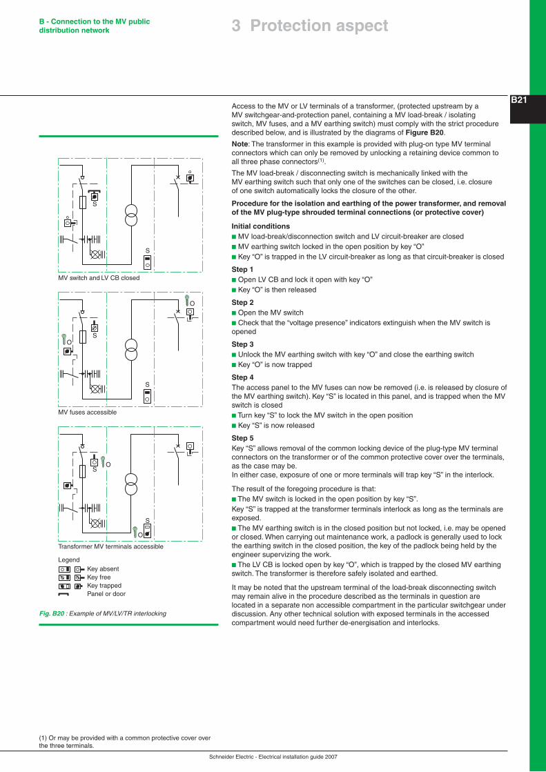
Schneider Electric - Electrical installation guide 2007
B - Connection to the MV public distribution network
B21Access to the MV or LV terminals of a transformer, (protected upstream by a MV switchgear-and-protection panel, containing a MV load-break / isolating switch, MV fuses, and a MV earthing switch) must comply with the strict procedure described below, and is illustrated by the diagrams of Figure B20.
Note: The transformer in this example is provided with plug-on type MV terminal connectors which can only be removed by unlocking a retaining device common to all three phase connectors(1).
The MV load-break / disconnecting switch is mechanically linked with the MV earthing switch such that only one of the switches can be closed, i.e. closure of one switch automatically locks the closure of the other.
Procedure for the isolation and earthing of the power transformer, and removal of the MV plug-type shrouded terminal connections (or protective cover)
Initial conditionsb MV load-break/disconnection switch and LV circuit-breaker are closedb MV earthing switch locked in the open position by key “O”b Key “O” is trapped in the LV circuit-breaker as long as that circuit-breaker is closed
Step 1b Open LV CB and lock it open with key “O”b Key “O” is then released
Step 2b Open the MV switchb Check that the “voltage presence” indicators extinguish when the MV switch is opened
Step 3b Unlock the MV earthing switch with key “O” and close the earthing switchb Key “O” is now trapped
Step 4The access panel to the MV fuses can now be removed (i.e. is released by closure of the MV earthing switch). Key “S” is located in this panel, and is trapped when the MV switch is closedb Turn key “S” to lock the MV switch in the open positionb Key “S” is now released
Step 5Key “S” allows removal of the common locking device of the plug-type MV terminal connectors on the transformer or of the common protective cover over the terminals, as the case may be.In either case, exposure of one or more terminals will trap key “S” in the interlock.
The result of the foregoing procedure is that:b The MV switch is locked in the open position by key “S”.Key “S” is trapped at the transformer terminals interlock as long as the terminals are exposed.b The MV earthing switch is in the closed position but not locked, i.e. may be opened or closed. When carrying out maintenance work, a padlock is generally used to lock the earthing switch in the closed position, the key of the padlock being held by the engineer supervizing the work.b The LV CB is locked open by key “O”, which is trapped by the closed MV earthing switch. The transformer is therefore safely isolated and earthed.
It may be noted that the upstream terminal of the load-break disconnecting switch may remain alive in the procedure described as the terminals in question are located in a separate non accessible compartment in the particular switchgear under discussion. Any other technical solution with exposed terminals in the accessed compartment would need further de-energisation and interlocks.
(1) Or may be provided with a common protective cover over the three terminals.
Fig. B20 : Example of MV/LV/TR interlocking
S
S
S
S
S
S
Panel or door
Legend
MV switch and LV CB closed
MV fuses accessible
Transformer MV terminals accessible
Key absentKey freeKey trapped
O
O
O
O
3 Protection aspect

Schneider Electric - Electrical installation guide 2007
B - Connection to the MV public distribution network
C224.1 General
A consumer substation with LV metering is an electrical installation connected to a utility supply system at a nominal voltage of 1 kV - 35 kV, and includes a single MV/LV transformer generally not exceeding 1,250 kVA.
FunctionsThe substationAll component parts of the substation are located in one room, either in an existing building, or in the form of a prefabricated housing exterior to the building.
Connection to the MV networkConnection at MV can be:b Either by a single service cable or overhead line, orb Via two mechanically interlocked load-break switches with two service cables from duplicate supply feeders, orb Via two load-break switches of a ring-main unit
The transformerSince the use of PCB(1)-filled transformers is prohibited in most countries, the preferred available technologies are:b Oil-immersed transformers for substations located outside premisesb Dry-type, vacuum-cast-resin transformers for locations inside premises, e.g. multistoreyed buildings, buildings receiving the public, and so on...
MeteringMetering at low voltage allows the use of small metering transformers at modest cost.Most tariff structures take account of transformer losses.
LV installation circuitsA low-voltage circuit-breaker, suitable for isolation duty and locking off facilities, to:b Supply a distribution boardb Protect the transformer against overloading and the downstream circuits against short-circuit faults.
One-line diagramsThe diagrams on the following page (see Fig. B21) represent the different methods of MV service connection, which may be one of four types:b Single-line serviceb Single-line service (equipped for extension to form a ring main)b Duplicate supply serviceb Ring main service
4.2 Choice of panels
Standards and specificationsThe switchgear and equipments described below are rated for 1 kV - 24 kV systems and comply with the following international standards:IEC 62271-200, 60265-1, 60694, 62271-102, 62271-105
Local regulations can also require compliance with national standards as:b France: UTEb United Kingdom: BSb Germany: VDEb United States of America: ANSI
Type of equipmentIn addition of Ring Main Units discussed in section 1.2, all kinds of switchgear arrangements are possible when using modular compartmented panels, and provisions for later extensions are easily realized.
Compact substations of modular panels are particularly applicable in the following cases:b Open ring or radial networkb Severe climatic or heavily-polluted conditions (integral insulation)b Insufficient space for “classical” switchboards
This type of equipment is distinguished by its reduced dimensions, its integrated functions and by its operational flexibility.
4 The consumer substation with LV metering
(1) Polychlorinated biphenyl

Schneider Electric - Electrical installation guide 2007
B - Connection to the MV public distribution network
C23
Fig. B21 : Consumer substation with LV metering
Power supply system
Service connection
MV protection andMV/LV transformation
LV meteringand isolation
LV distributionand protection
Supplier/consumer interface
Downstream terminals of LV isolator
Transformer LV terminals
Protection
Protection
Protection+Auto-changeoverswitch
Protection
Protection
Duplicate-supply service
Single-line service (equipped for extension to form a ring main)
Single-line service
Ring mainservice Automatic
LV standbysource
Permitted if IMV nominaly 45 A and one transformer
Permitted if IMV nominaly 45 A and one transformer
Always permitted
4 The consumer substation with LV metering
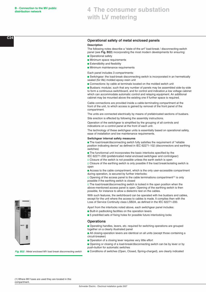
Schneider Electric - Electrical installation guide 2007
B - Connection to the MV public distribution network
C24
(1) Where MV fuses are used they are located in this compartment.
Operational safety of metal enclosed panelsDescriptionThe following notes describe a “state-of-the art” load-break / disconnecting-switch panel (see Fig. B22) incorporating the most modern developments for ensuring:b Operational safetyb Minimum space requirementsb Extendibility and flexibilityb Minimum maintenance requirements
Each panel includes 3 compartments:b Switchgear: the load-break disconnecting switch is incorporated in an hermetically sealed (for life) molded epoxy-resin unitb Connections: by cable at terminals located on the molded switch unitb Busbars: modular, such that any number of panels may be assembled side-by-side to form a continuous switchboard, and for control and indication,a low voltage cabinet which can accommodate automatic control and relaying equipment. An additional cabinet may be mounted above the existing one if further space is required.
Cable connections are provided inside a cable-terminating compartment at the front of the unit, to which access is gained by removal of the front panel of the compartment.
The units are connected electrically by means of prefabricated sections of busbars.
Site erection is effected by following the assembly instructions.
Operation of the switchgear is simplified by the grouping of all controls and indications on a control panel at the front of each unit.
The technology of these switchgear units is essentially based on operational safety, ease of installation and low maintenance requirements.
Switchgear internal safety measures b The load-break/disconnecting switch fully satisfies the requirement of “reliable position indicating device” as defined in IEC 62271-102 (disconnectors and earthing switches)b The functionnal unit incorporates the basic interlocks specified by the IEC 62271-200 (prefabricated metal enclosed switchgear and controlgear):v Closure of the switch is not possible unless the earth switch is open v Closure of the earthing switch is only possible if the load break/isolating switch is openb Access to the cable compartment, which is the only user-accessible compartment during operation, is secured by further interlocks:v Opening of the access panel to the cable terminations compartment(1) is only possible if the earthing switch is closedv The load-break/disconnecting switch is locked in the open position when the above-mentioned access panel is open. Opening of the earthing switch is then possible, for instance to allow a dielectric test on the cables.
With such features, the switchboard can be operated with live busbars and cables, except for the unit where the access to cables is made. It complies then with the Loss of Service Continuity class LSB2A, as defined in the IEC 62271-200.
Apart from the interlocks noted above, each switchgear panel includes:b Built-in padlocking facilities on the operation leversb 5 predrilled sets of fixing holes for possible future interlocking locks
Operationsb Operating handles, levers, etc. required for switching operations are grouped together on a clearly illustrated panelb All closing-operation levers are identical on all units (except those containing a circuit-breaker)b Operation of a closing lever requires very little effortb Opening or closing of a load-break/disconnecting switch can be by lever or by push-button for automatic switchesb Conditions of switches (Open, Closed, Spring-charged), are clearly indicatedFig. B22 : Metal enclosed MV load break disconnecting switch
4 The consumer substation with LV metering
Schneider Electric - Electrical installation guide 2007
B - Connection to the MV public distribution network
C254.3 Choice of MV switchgear panel for a transformer circuit
Three types of MV switchgear panel are generally available:b Load-break switch and separate MV fuses in the panelb Load-break switch/MV fuses combinationb Circuit-breaker
Seven parameters influence the optimum choice:b The primary current of the transformerb The insulating medium of the transformerb The position of the substation with respect to the load centreb The kVA rating of the transformerb The distance from switchgear to the transformerb The use of separate protection relays (as opposed to direct-acting trip coils).
Note: The fuses used in the load-break/switch fuses combination have striker-pins which ensure tripping of the 3-pole switch on the operation of one (or more) fuse(s).
4.4 Choice of MV/LV transformer
Characteristic parameters of a transformerA transformer is characterized in part by its electrical parameters, but also by its technology and its conditions of use.
Electrical characteristicsb Rated power (Pn): the conventional apparent-power in kVA on which other design-parameter values and the construction of the transformer are based. Manufacturing tests and guarantees are referred to this ratingb Frequency: for power distribution systems of the kind discussed in this guide, the frequency will be 50 Hz or 60 Hzb Rated primary and secondary voltages: For a primary winding capable of operating at more than one voltage level, a kVA rating corresponding to each level must be given.The secondary rated voltage is its open circuit valueb Rated insulation levels are given by overvoltage-withstand test values at power frequency, and by high voltage impulse tests which simulate lightning discharges. At the voltage levels discussed in this guide, overvoltages caused by MV switching operations are generally less severe than those due to lightning, so that no separate tests for switching-surge withstand capability are madeb Off-circuit tap-selector switch generally allows a choice of up to ± 2.5% and ± 5% level about the rated voltage of the highest voltage winding. The transformer must be de-energized before this switch is operatedb Winding configurations are indicated in diagrammatic form by standard symbols for star, delta and inter-connected-star windings; (and combinations of these for special duty, e.g. six-or twelve-phase rectifier transformers, etc.) and in an IEC-recommended alphanumeric code. This code is read from left-to-right, the first letter refers to the highest voltage winding, the second letter to the next highest, and so on:v Capital letters refer to the highest voltage windingD = deltaY = starZ = interconnected-star (or zigzag)N = neutral connection brought out to a terminalv Lower-case letters are used for tertiary and secondary windingsd = deltay = starz = interconnected-star (or zigzag)n = neutral connection brought out to a terminalv A number from 0 to 11, corresponding to those, on a clock dial (“0” is used instead of “12”) follows any pair of letters to indicate the phase change (if any) which occurs during the transformation.
A very common winding configuration used for distribution transformers is that of a Dyn 11 transformer, which has a delta MV winding with a star-connected secondary winding the neutral point of which is brought out to a terminal. The phase change through the transformer is +30 degrees, i.e. phase 1 secondary voltage is at “11 o’clock” when phase 1 of the primary voltage is at “12 o’clock”, as shown in Figure B31 page B34. All combinations of delta, star and zigzag windings produce a phase change which (if not zero) is either 30 degrees or a multiple of 30 degrees.IEC 60076-4 describes the “clock code” in detail.
4 The consumer substation with LV metering

Schneider Electric - Electrical installation guide 2007
B - Connection to the MV public distribution network
C26Characteristics related to the technology and utilization of the transformerThis list is not exhaustive:b Choice of technologyThe insulating medium is:v Liquid (mineral oil) orv Solid (epoxy resin and air)b For indoor or outdoor installationb Altitude (<= 1,000 m is standard)b Temperature (IEC 60076-2)v Maximum ambient air: 40 °Cv Daily maximum average ambient air: 30 °Cv Annual maximum average ambient air: 20 °C
For non-standard operating conditions, refer to “Influence of the Ambient temperature and altitude on the rated current” on page B7.
Description of insulation techniquesThere are two basic classes of distribution transformer presently available:b Dry type (cast in resin)b Liquid filled (oil-immersed)
Dry type transformersThe windings of these transformers are insulated by resin cast under vacuum (which is patented by major manufacturers).
It is recommended that the transformer be chosen according to the IEC 60076-11, as follows:b Environment class E2 (frequent condensation and/or high level of pollution)b Climatic conditions class B2 (utilization, transport and stockage down to -25 °C)b Fire resistance (transformers exposed to fire risk with low flammability and self extinguishing in a given time)
The following description refers to the process developed by a leading European manufacturer in this field.The encapsulation of a winding uses three components:b Epoxy-resin based on biphenol A with a viscosity that ensures complete impregnation of the windingsb Anhydride hardener modified to introduce a degree of resilience in the moulding, essential to avoid the development of cracks during the temperature cycles occurring in normal operationb Pulverulent additive composed of trihydrated alumina Al (OH)3 and silica which enhances its mechanical and thermal properties, as well as giving exceptional intrinsic qualities to the insulation in the presence of heat.
This three-component system of encapsulation gives Class F insulation (Δθ = 100 K) with excellent fire-resisting qualities and immediate self-extinction. These transformers are therefore classified as nonflammable.
The mouldings of the windings contain no halogen compounds (chlorine, bromine, etc.) or other compounds capable of producing corrosive or toxic pollutants, thereby guaranteeing a high degree of safety to personnel in emergency situations, notably in the event of a fire.
It also performs exceptionally well in hostile industrial atmospheres of dust, humidity, etc. (see Fig. B23).
Liquid-filled transformersThe most common insulating/cooling liquid used in transformers is mineral oil. Mineral oils are specified in IEC 60296. Being flammable, safety measures are obligatory in many countries, especially for indoor substations. The DGPT unit (Detection of Gas, Pressure and Temperature) ensures the protection of oil-filled transformers. In the event of an anomaly, the DGPT causes the MV supply to the transformer to be cut off very rapidly, before the situation becomes dangerous.
Mineral oil is bio-degradable and does not contain PCB (polychlorinated biphenyl), which was the reason for banning askerel, i.e. Pyralène, Pyrolio, Pyroline...On request, mineral oil can be replaced by an alternative insulating liquid, by adapting the transformer, as required, and taking appropriate additional precautions if necessary.
The insulating fluid also acts as a cooling medium; it expands as the load and/or the ambient temperature increases, so that all liquid-filled transformers must be designed to accommodate the extra volume of liquid without the pressure in the tank becoming excessive.
Fig. B23 : Dry-type transformer
4 The consumer substation with LV metering
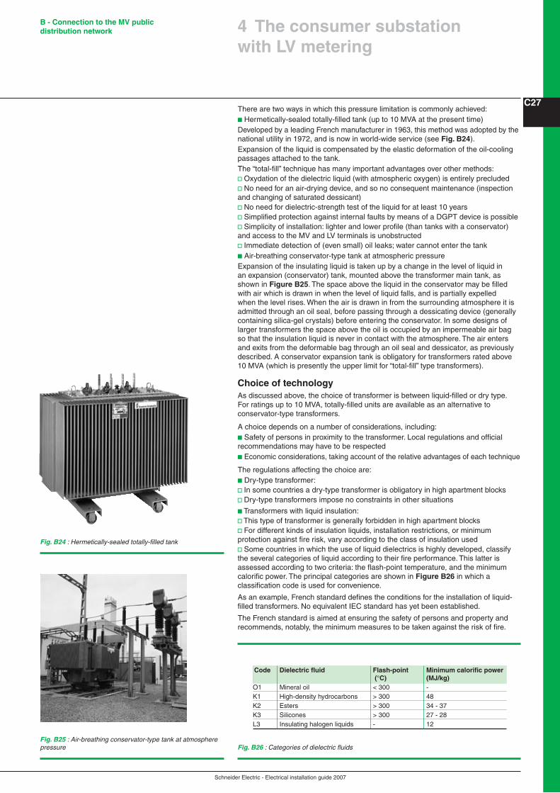
Schneider Electric - Electrical installation guide 2007
B - Connection to the MV public distribution network
C27There are two ways in which this pressure limitation is commonly achieved:b Hermetically-sealed totally-filled tank (up to 10 MVA at the present time)Developed by a leading French manufacturer in 1963, this method was adopted by the national utility in 1972, and is now in world-wide service (see Fig. B24).Expansion of the liquid is compensated by the elastic deformation of the oil-cooling passages attached to the tank.The “total-fill” technique has many important advantages over other methods:v Oxydation of the dielectric liquid (with atmospheric oxygen) is entirely precludedv No need for an air-drying device, and so no consequent maintenance (inspection and changing of saturated dessicant)v No need for dielectric-strength test of the liquid for at least 10 yearsv Simplified protection against internal faults by means of a DGPT device is possiblev Simplicity of installation: lighter and lower profile (than tanks with a conservator) and access to the MV and LV terminals is unobstructedv Immediate detection of (even small) oil leaks; water cannot enter the tankb Air-breathing conservator-type tank at atmospheric pressureExpansion of the insulating liquid is taken up by a change in the level of liquid in an expansion (conservator) tank, mounted above the transformer main tank, as shown in Figure B25. The space above the liquid in the conservator may be filled with air which is drawn in when the level of liquid falls, and is partially expelled when the level rises. When the air is drawn in from the surrounding atmosphere it is admitted through an oil seal, before passing through a dessicating device (generally containing silica-gel crystals) before entering the conservator. In some designs of larger transformers the space above the oil is occupied by an impermeable air bag so that the insulation liquid is never in contact with the atmosphere. The air enters and exits from the deformable bag through an oil seal and dessicator, as previously described. A conservator expansion tank is obligatory for transformers rated above 10 MVA (which is presently the upper limit for “total-fill” type transformers).
Choice of technologyAs discussed above, the choice of transformer is between liquid-filled or dry type.For ratings up to 10 MVA, totally-filled units are available as an alternative to conservator-type transformers.
A choice depends on a number of considerations, including:b Safety of persons in proximity to the transformer. Local regulations and official recommendations may have to be respectedb Economic considerations, taking account of the relative advantages of each technique
The regulations affecting the choice are:b Dry-type transformer:v In some countries a dry-type transformer is obligatory in high apartment blocksv Dry-type transformers impose no constraints in other situations
b Transformers with liquid insulation:v This type of transformer is generally forbidden in high apartment blocksv For different kinds of insulation liquids, installation restrictions, or minimum protection against fire risk, vary according to the class of insulation usedv Some countries in which the use of liquid dielectrics is highly developed, classify the several categories of liquid according to their fire performance. This latter is assessed according to two criteria: the flash-point temperature, and the minimum calorific power. The principal categories are shown in Figure B26 in which a classification code is used for convenience.
As an example, French standard defines the conditions for the installation of liquid-filled transformers. No equivalent IEC standard has yet been established.
The French standard is aimed at ensuring the safety of persons and property and recommends, notably, the minimum measures to be taken against the risk of fire.
Fig. B25 : Air-breathing conservator-type tank at atmosphere pressure
Fig. B24 : Hermetically-sealed totally-filled tank
Fig. B26 : Categories of dielectric fluids
Code Dielectric fluid Flash-point Minimum calorific power (°C) (MJ/kg)O1 Mineral oil < 300 -K1 High-density hydrocarbons > 300 48 K2 Esters > 300 34 - 37K3 Silicones > 300 27 - 28L3 Insulating halogen liquids - 12
4 The consumer substation with LV metering
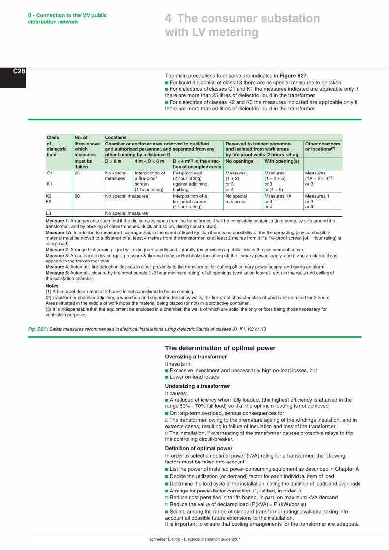
Schneider Electric - Electrical installation guide 2007
B - Connection to the MV public distribution network
C28The main precautions to observe are indicated in Figure B27.b For liquid dielectrics of class L3 there are no special measures to be takenb For dielectrics of classes O1 and K1 the measures indicated are applicable only if there are more than 25 litres of dielectric liquid in the transformerb For dielectrics of classes K2 and K3 the measures indicated are applicable only if there are more than 50 litres of dielectric liquid in the transformer.
The determination of optimal powerOversizing a transformerIt results in:b Excessive investment and unecessarily high no-load losses, butb Lower on-load losses
Undersizing a transformerIt causes:b A reduced efficiency when fully loaded, (the highest efficiency is attained in the range 50% - 70% full load) so that the optimum loading is not achievedb On long-term overload, serious consequences forv The transformer, owing to the premature ageing of the windings insulation, and in extreme cases, resulting in failure of insulation and loss of the transformerv The installation, if overheating of the transformer causes protective relays to trip the controlling circuit-breaker.
Definition of optimal powerIn order to select an optimal power (kVA) rating for a transformer, the following factors must be taken into account:b List the power of installed power-consuming equipment as described in Chapter Ab Decide the utilization (or demand) factor for each individual item of loadb Determine the load cycle of the installation, noting the duration of loads and overloadsb Arrange for power-factor correction, if justified, in order to:v Reduce cost penalties in tariffs based, in part, on maximum kVA demandv Reduce the value of declared load (P(kVA) = P (kW)/cos ϕ)b Select, among the range of standard transformer ratings available, taking into account all possible future extensions to the installation.It is important to ensure that cooling arrangements for the transformer are adequate.
Class No. of Locationsof litres above Chamber or enclosed area reserved to qualified Reserved to trained personnel Other chambers dielectric which and authorized personnel, and separated from any and isolated from work areas or locations(2) fluid measures other building by a distance D by fire-proof walls (2 hours rating) must be D > 8 m 4 m < D < 8 m D < 4 m(1) in the direc- No openings With opening(s) taken tion of occupied areasO1 25 No special Interposition of Fire-proof wall Measures Measures Measures measures a fire-proof (2 hour rating) (1 + 2) (1 + 2 + 5) (1A + 2 + 4)(3) K1 screen against adjoining or 3 or 3 or 3 (1 hour rating) building or 4 or (4 + 5) K2 50 No special measures Interposition of a No special Measures 1A Measures 1 K3 fire-proof screen measures or 3 or 3 (1 hour rating) or 4 or 4L3 No special measures
Measure 1: Arrangements such that if the dielectric escapes from the transformer, it will be completely contained (in a sump, by sills around the transformer, and by blocking of cable trenches, ducts and so on, during construction).Measure 1A: In addition to measure 1, arrange that, in the event of liquid ignition there is no possibility of the fire spreading (any combustible material must be moved to a distance of at least 4 metres from the transformer, or at least 2 metres from it if a fire-proof screen [of 1 hour rating] is interposed).Measure 2: Arrange that burning liquid will extinguish rapidly and naturally (by providing a pebble bed in the containment sump).Measure 3: An automatic device (gas, pressure & thermal relay, or Buchholz) for cutting off the primary power supply, and giving an alarm, if gas appears in the transformer tank.Measure 4: Automatic fire-detection devices in close proximity to the transformer, for cutting off primary power supply, and giving an alarm.Measure 5: Automatic closure by fire-proof panels (1/2 hour minimum rating) of all openings (ventilation louvres, etc.) in the walls and ceiling of the substation chamber.
Notes:(1) A fire-proof door (rated at 2 hours) is not considered to be an opening.(2) Transformer chamber adjoining a workshop and separated from it by walls, the fire-proof characteristics of which are not rated for 2 hours. Areas situated in the middle of workshops the material being placed (or not) in a protective container.(3) It is indispensable that the equipment be enclosed in a chamber, the walls of which are solid, the only orifices being those necessary for ventilation purposes.
Fig. B27 : Safety measures recommended in electrical installations using dielectric liquids of classes 01, K1, K2 or K3
4 The consumer substation with LV metering

Schneider Electric - Electrical installation guide 2007
B - Connection to the MV public distribution network
C29Ventilation orificesIn the general case of cooling by natural air circulation (AN) the ventilation of the chamber is arranged to remove the heat (produced by losses in the transformer) by natural convection.
A good system of ventilation allows cool air to enter through an orifice of sectional area S at floor level, and to leave the chamber through an orifice of sectional area S’ on the opposite wall to that of the air entry and at a height H above the incoming-air orifice, as shown in Figure B28.
It is important to note that any restriction to the free flow of a sufficient volume of air will result in a reduction of power available from the transformer, if the rated temperature limit is not to be exceeded.
Natural ventilationThe formulae for calculating the sectional area of the ventilation orifices are as follows:follows:
S =0.18 P
H and S’ = 1.1 S
Where
WhereP = the sum of the no-load losses and the full-load losses expressed in kWS = the sectional area of the incoming-air orifice (area of louvres or grill to be deducted) expressed in mm2
S’ = the sectional area of the outgoing-air orifice (area of louvres or grill to be deducted) expressed in mm2
H = height (centre to centre) of the outgoing air orifice above the incoming-air orifice, expressed in metres.
The formulae are valid for a mean ambient temperature of 20 °C and up to an altitude of 1,000 m.
It must be noted that these formulae are able to determine only one order of magnitude of the sections S and S', which are qualified as thermal section, i.e. fully open and just necessary to evacuate the thermal energy generated inside the MV/LV substation.The pratical sections are of course larger according ot the adopted technological solution.
Indeed, the real air flow is strongly dependant:b on the openings shape and solutions adopted to ensure the cubicle protection index (IP): metal grid, stamped holes, chevron louvers,...b on internal components size and their position compared to the openings: transformer and/or retention oil box position and dimensions, flow channel between the components, ...b and on some physical and environmental parameters: outside ambient temperature, altitude, magnitude of the resulting temperature rise.
The understanding and the optimization of the attached physical phenomena are subject to precise flow studies, based on the fluid dynamics laws, and realized with specific analytic software.
Forced ventilationForced (i.e. electric-fan assisted) ventilation of the chamber is necessary for ambient temperatures exceeding 20 °C, or if the chamber is badly ventilated; frequent overloading of the transformer, and so on...
The fan can be controlled by thermostat.
Recommended air-flow rate, in cubic metres per second at 20 °C:b Totally-filled transformer: 0.081 Pb Dry-type Class F transformer: 0.05 Pwhere P = total losses in kW.
4 The consumer substation with LV metering
Fig. B28 : Natural ventilation
S'
S
H

Schneider Electric - Electrical installation guide 2007
B - Connection to the MV public distribution network
B305.1 General
FunctionsThe substation
According to the complexity of the installation and the manner in which the load is divided, the substation:b Might include one room containing the MV switchboard and metering panel(s), together with the transformer(s) and low-voltage main distribution board(s),b Or might supply one or more transformer rooms, which include local LV distribution boards, supplied at MV from switchgear in a main substation, similar to that described above.
These substations may be installed, either:b Inside a building, orb Outdoors in prefabricated housings.
Connection to the MV networkConnection at MV can be:b Either by a single service cable or overhead line, orb Via two mechanically interlocked load-break switches with two service cables from duplicate supply feeders, orb Via two load-break switches of a ring-main unit.
MeteringBefore the installation project begins, the agreement of the power-supply utility regarding metering arrangements must be obtained.
A metering panel will be incorporated in the MV switchboard. Voltage transformers and current transformers, having the necessary metering accuracy, may be included in the main incoming circuit-breaker panel or (in the case of the voltage transformer) may be installed separately in the metering panel.
Transformer roomsIf the installation includes a number of transformer rooms, MV supplies from the main substation may be by simple radial feeders connected directly to the transformers, or by duplicate feeders to each room, or again, by a ring-main, according to the degree of supply availability desired.
In the two latter cases, 3-panel ring-main units will be required at each transformer room.
Local emergency generatorsEmergency standby generators are intended to maintain a power supply to essential loads, in the event of failure of the power supply system.
CapacitorsCapacitors will be installed, according to requirements:b In stepped MV banks at the main substation, orb At LV in transformer rooms.
TransformersFor additional supply-security reasons, transformers may be arranged for automatic changeover operation, or for parallel operation.
One-line diagramsThe diagrams shown in Figure B29 next page represent:b The different methods of MV service connection, which may be one of four types:v Single-line servicev Single-line service (equipped for extension to form a ring main)v Duplicate supply servicev Ring main serviceb General protection at MV, and MV metering functionsb Protection of outgoing MV circuitsb Protection of LV distribution circuits
5 The consumer substation with MV metering
A consumer substation with MV metering is an electrical installation connected to a utility supply system at a nominal voltage of 1 kV - 35 kV and generally includes a single MV/LV transformer which exceeds 1,250 kVA, or several smaller transformers.The rated current of the MV switchgear does not normally exceed 400 A.

Schneider Electric - Electrical installation guide 2007
B - Connection to the MV public distribution network
B31
Power supplysystem
Service connection MV protectionand metering
MV distribution and protectionof outgoing circuits
LV distributionand protection
Supplier/consumerinterface
Downstream terminals of MV isolator for the installation
LV terminals oftransformer
Duplicate-supplyservice
Ring-mainservice
Single-line service(equipped for extension to form a ring main)
Protection+ automaticchangeoverfeature
Automatic LVstandby source
Protection
ProtectionLV
Automatic LV/MVstandby source
I nominal of transformer u 45 A
A single transformer
Single-line service
Fig. B29 : Consumer substation with MV metering
5 The consumer substation with MV metering

Schneider Electric - Electrical installation guide 2007
B - Connection to the MV public distribution network
B325.2 Choice of panels
A substation with MV metering includes, in addition to the panels described in 4.2, panels specifically designed for metering and, if required, for automatic or manual changeover from one source to another.
Metering and general protectionThese two functions are achieved by the association of two panels:b One panel containing the VTb The main MV circuit-breaker panel containing the CTs for measurement and protection
The general protection is usually against overcurrent (overload and short-circuit) and earth faults. Both schemes use protective relays which are sealed by the power-supply utility.
Substation including generatorsGenerator in stand alone operationIf the installation needs great power supply availability, a MV standby generator set can be used. In such a case, the installation must include an automatic changeover. In order to avoid any posssibility of parallel operation of the generator with the power supply network, a specific panel with automatic changeover is needed (see Fig. B30).
b ProtectionSpecific protective devices are intended to protect the generator itself. It must be noted that, due to the very low short-circuit power of the generator comparing with the power supply network, a great attention must be paid to protection discrimination.
b ControlA voltage regulator controlling an alternator is generally arranged to respond to a reduction of voltage at its terminals by automatically increasing the excitation current of the alternator, until the voltage is restored to normal. When it is intended that the alternator should operate in parallel with others, the AVR (Automatic Voltage Regulator) is switched to “parallel operation” in which the AVR control circuit is slightly modified (compounded) to ensure satisfactory sharing of kvars with the other parallel machines.
When a number of alternators are operating in parallel under AVR control, an increase in the excitation current of one of them (for example, carried out manually after switching its AVR to Manual control) will have practically no effect on the voltage level. In fact, the alternator in question will simply operate at a lower power factor (more kVA, and therefore more current) than before.
The power factor of all the other machines will automatically improve, such that the load power factor requirements are satisfied, as before.
Generator operating in parallel with the utility supply networkTo connect a generator set on the network, the agreement of the power supply utility is usually required. Generally the equipement (panels, protection relays) must be approved by the utility.The following notes indicate some basic consideration to be taken into account for protection and control.
b ProtectionTo study the connection of generator set, the power supply utility needs some data as follows :v Power injected on the networkv Connection modev Short-circuit current of the generator setv Voltage unbalance of the generatorv etc.
Depending on the connection mode, dedicated uncoupling protection functions are required :v Under-voltage and over-voltage protectionv Under-frequency and over-frequency protectionv Zero sequence overvoltage protectionv Maximum time of coupling (for momentary coupling)v Reverse real power
For safety reasons, the switchgear used for uncoupling must also be provided with the characteristics of a disconnector (i.e total isolation of all active conductors between the generator set and the power supply network).
Fig. B30 : Section of MV switchboard including standby supply panel
From standby generator P y 20,000 kVA
MV distribution panels for which standby supply is required
Automaticchangeoverpanel
Busbartransitionpanel
To remainder of the MV switchboard
5 The consumer substation with MV metering

Schneider Electric - Electrical installation guide 2007
B - Connection to the MV public distribution network
B33b ControlWhen generators at a consumer’s substation operate in parallel with all the generation of the utility power supply system, supposing the power system voltage is reduced for operational reasons (it is common to operate MV systems within a range of ± 5% of nominal voltage, or even more, where load-flow patterns require it), an AVR set to maintain the voltage within ± 3% (for example) will immediately attempt to raise the voltage by increasing the excitation current of the alternator.
Instead of raising the voltage, the alternator will simply operate at a lower power factor than before, thereby increasing its current output, and will continue to do so, until it is eventually tripped out by its overcurrent protective relays. This is a well-known problem and is usually overcome by the provision of a “constant power- factor” control switch on the AVR unit.
By making this selection, the AVR will automatically adjust the excitation current to match whatever voltage exists on the power system, while at the same time maintaining the power factor of the alternator constant at the pre-set value (selected on the AVR control unit).
In the event that the alternator becomes decoupled from the power system, the AVR must be automatically (rapidly) switched back to “constant-voltage” control.
5.3 Parallel operation of transformers
The need for operation of two or more transformers in parallel often arises due to:b Load growth, which exceeds the capactiy of an existing transformerb Lack of space (height) for one large transformerb A measure of security (the probability of two transformers failing at the same time is very small)b The adoption of a standard size of transformer throughout an installation
Total power (kVA)The total power (kVA) available when two or more transformers of the same kVA rating are connected in parallel, is equal to the sum of the individual ratings, providing that the percentage impedances are all equal and the voltage ratios are identical.
Transformers of unequal kVA ratings will share a load practically (but not exactly) in proportion to their ratings, providing that the voltage ratios are identical and the per-centage impedances (at their own kVA rating) are identical, or very nearly so. In these cases, a total of more than 90% of the sum of the two ratings is normally available.
It is recommended that transformers, the kVA ratings of which differ by more than 2:1, should not be operated permanently in parallel.
Conditions necessary for parallel operationAll paralleled units must be supplied from the same network.
The inevitable circulating currents exchanged between the secondary circuits of paralleled transformers will be negligibly small providing that:b Secondary cabling from the transformers to the point of paralleling have approximately equal lengths and characteristicsb The transformer manufacturer is fully informed of the duty intended for the transformers, so that:v The winding configurations (star, delta, zigzag star) of the several transformers have the same phase change between primary and secondary voltagesv The short-circuit impedances are equal, or differ by less than 10%v Voltage differences between corresponding phases must not exceed 0.4%v All possible information on the conditions of use, expected load cycles, etc. should be given to the manufacturer with a view to optimizing load and no-load losses
5 The consumer substation with MV metering
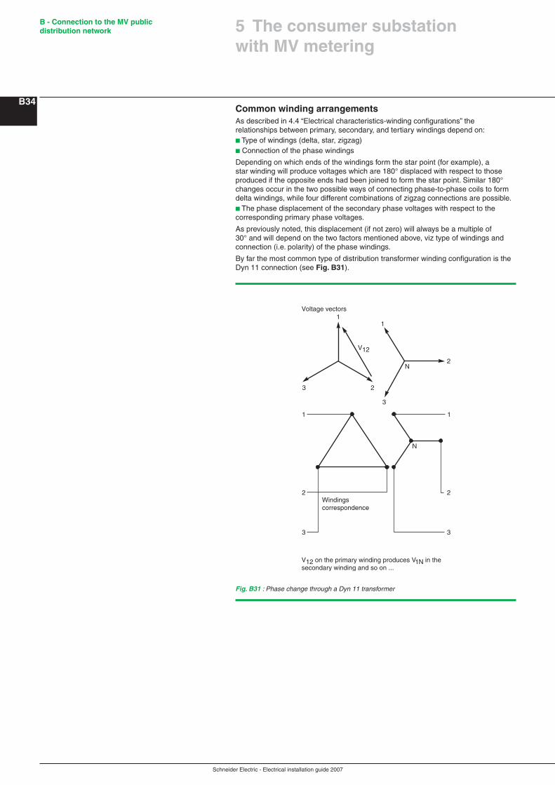
Schneider Electric - Electrical installation guide 2007
B - Connection to the MV public distribution network
B34Common winding arrangementsAs described in 4.4 “Electrical characteristics-winding configurations” the relationships between primary, secondary, and tertiary windings depend on:b Type of windings (delta, star, zigzag)b Connection of the phase windings
Depending on which ends of the windings form the star point (for example), a star winding will produce voltages which are 180° displaced with respect to those produced if the opposite ends had been joined to form the star point. Similar 180° changes occur in the two possible ways of connecting phase-to-phase coils to form delta windings, while four different combinations of zigzag connections are possible.b The phase displacement of the secondary phase voltages with respect to the corresponding primary phase voltages.
As previously noted, this displacement (if not zero) will always be a multiple of 30° and will depend on the two factors mentioned above, viz type of windings and connection (i.e. polarity) of the phase windings.
By far the most common type of distribution transformer winding configuration is the Dyn 11 connection (see Fig. B31).
Fig. B31 : Phase change through a Dyn 11 transformer
1
23
V12
1
2
3
N
1
2
3
Voltage vectors
V12 on the primary winding produces V1N in the secondary winding and so on ...
Windingscorrespondence
1
2
3
N
5 The consumer substation with MV metering
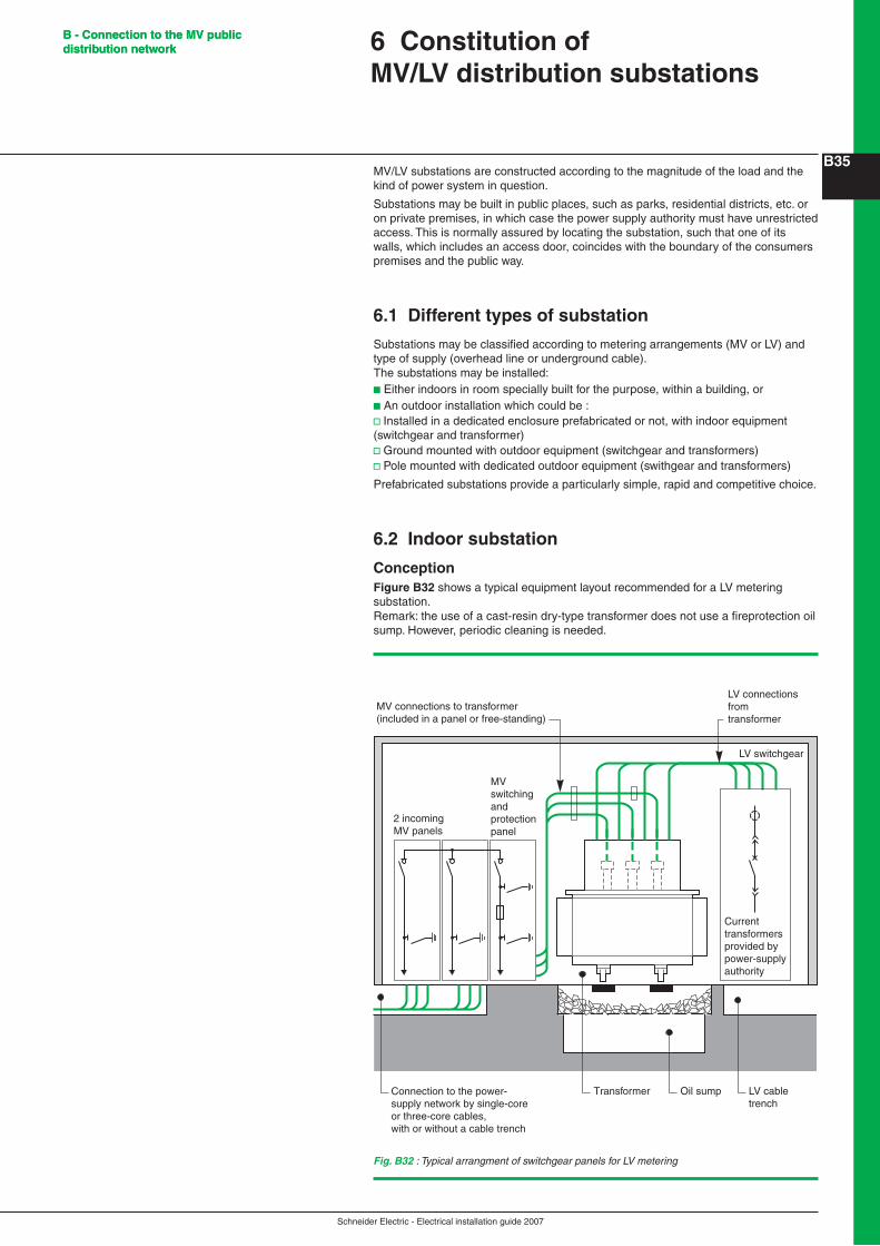
Schneider Electric - Electrical installation guide 2007
B - Connection to the MV public distribution network
B35
B - Connection to the MV public distribution network
MV/LV substations are constructed according to the magnitude of the load and the kind of power system in question.
Substations may be built in public places, such as parks, residential districts, etc. or on private premises, in which case the power supply authority must have unrestricted access. This is normally assured by locating the substation, such that one of its walls, which includes an access door, coincides with the boundary of the consumers premises and the public way.
6.1 Different types of substation
Substations may be classified according to metering arrangements (MV or LV) and type of supply (overhead line or underground cable).The substations may be installed:b Either indoors in room specially built for the purpose, within a building, orb An outdoor installation which could be :v Installed in a dedicated enclosure prefabricated or not, with indoor equipment (switchgear and transformer)v Ground mounted with outdoor equipment (switchgear and transformers)v Pole mounted with dedicated outdoor equipment (swithgear and transformers)
Prefabricated substations provide a particularly simple, rapid and competitive choice.
6.2 Indoor substation
ConceptionFigure B32 shows a typical equipment layout recommended for a LV metering substation.Remark: the use of a cast-resin dry-type transformer does not use a fireprotection oil sump. However, periodic cleaning is needed.
6 Constitution of MV/LV distribution substations
Fig. B32 : Typical arrangment of switchgear panels for LV metering
LV switchgear
LV connections fromtransformer
MV connections to transformer(included in a panel or free-standing)
2 incomingMV panels
MV switching and protection panel
Transformer LV cable trench
Oil sumpConnection to the power-supply network by single-core or three-core cables, with or without a cable trench
Current transformers provided by power-supply authority

Schneider Electric - Electrical installation guide 2007
B - Connection to the MV public distribution network
B36Service connections and equipment interconnectionsAt high voltageb Connections to the MV system are made by, and are the responsibility of the utilityb Connections between the MV switchgear and the transformers may be:v By short copper bars where the transformer is housed in a panel forming part of the MV switchboardv By single-core screened cables with synthetic insulation, with possible use of plug-in type terminals at the transformer
At low voltageb Connections between the LV terminals of the transformer and the LV switchgear may be:v Single-core cablesv Solid copper bars (circular or rectangular section) with heat-shrinkable insulation
Metering (see Fig. B33)b Metering current transformers are generally installed in the protective cover of the power transformer LV terminals, the cover being sealed by the supply utilityb Alternatively, the current transformers are installed in a sealed compartment within the main LV distribution cabinetb The meters are mounted on a panel which is completely free from vibrationsb Placed as close to the current transformers as possible, andb Are accessible only to the utility
Fig. B33 : Plan view of typical substation with LV metering
800 mini
MV supply LV distribution
Meters
100
Safety accessoriesCommon earth busbar for the substation
Earthing circuitsThe substation must include:
b An earth electrode for all exposed conductive parts of electrical equipment in the substation and exposed extraneous metal including:v Protective metal screensv Reinforcing rods in the concrete base of the substation
Substation lightingSupply to the lighting circuits can be taken from a point upstream or downstream of the main incoming LV circuit-breaker. In either case, appropriate overcurrent protection must be provided. A separate automatic circuit (or circuits) is (are) recommended for emergency lighting purposes.
Operating switches, pushbuttons, etc. are normally located immediately adjacent to entrances.
Lighting fittings are arranged such that:b Switchgear operating handles and position indication markings are adequately illuminatedb All metering dials and instruction plaques and so on, can be easily read
6 Constitution of MV/LV distribution substations
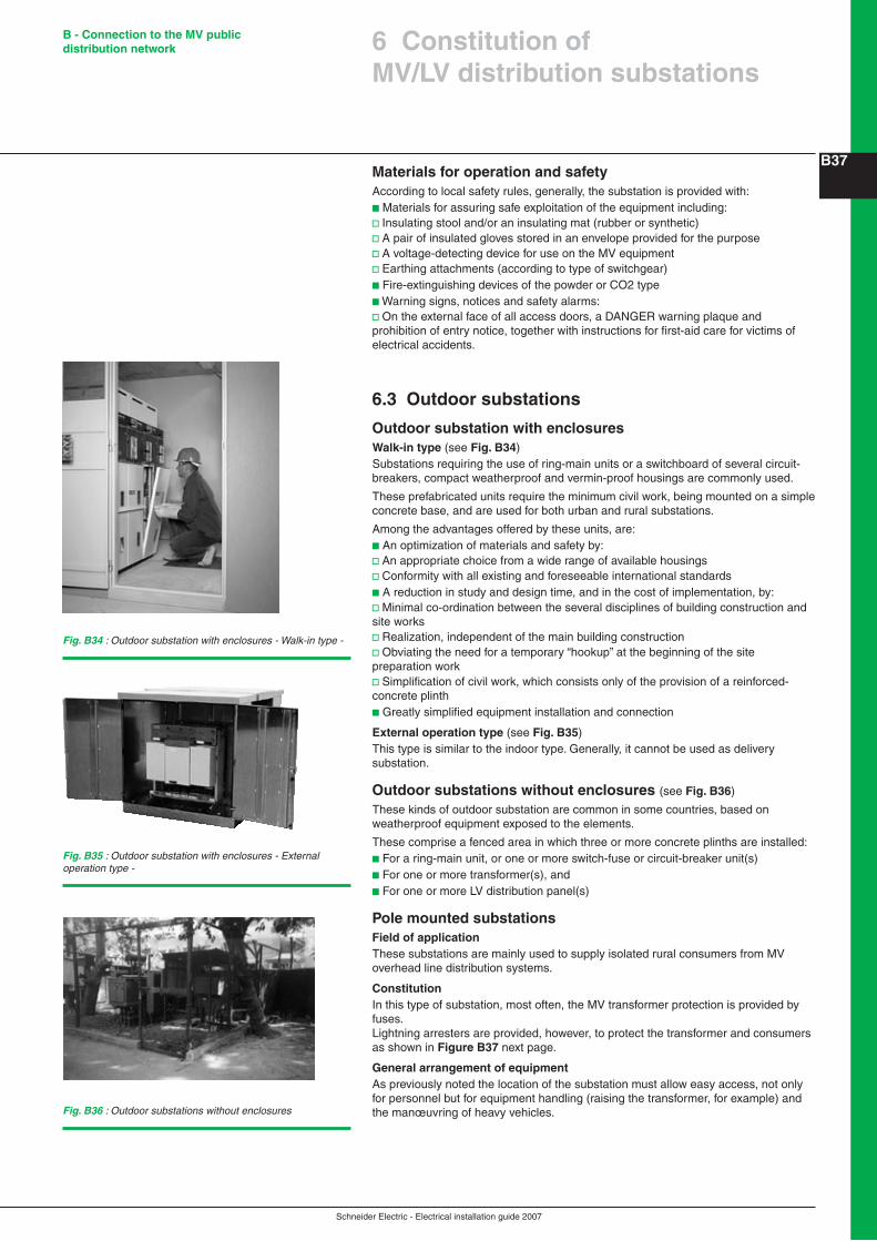
Schneider Electric - Electrical installation guide 2007
B - Connection to the MV public distribution network
B37Materials for operation and safetyAccording to local safety rules, generally, the substation is provided with:b Materials for assuring safe exploitation of the equipment including:v Insulating stool and/or an insulating mat (rubber or synthetic)v A pair of insulated gloves stored in an envelope provided for the purposev A voltage-detecting device for use on the MV equipmentv Earthing attachments (according to type of switchgear)b Fire-extinguishing devices of the powder or CO2 typeb Warning signs, notices and safety alarms:v On the external face of all access doors, a DANGER warning plaque and prohibition of entry notice, together with instructions for first-aid care for victims of electrical accidents.
6.3 Outdoor substations
Outdoor substation with enclosuresWalk-in type (see Fig. B34)Substations requiring the use of ring-main units or a switchboard of several circuit-breakers, compact weatherproof and vermin-proof housings are commonly used.
These prefabricated units require the minimum civil work, being mounted on a simple concrete base, and are used for both urban and rural substations.
Among the advantages offered by these units, are:b An optimization of materials and safety by:v An appropriate choice from a wide range of available housingsv Conformity with all existing and foreseeable international standardsb A reduction in study and design time, and in the cost of implementation, by:v Minimal co-ordination between the several disciplines of building construction and site worksv Realization, independent of the main building constructionv Obviating the need for a temporary “hookup” at the beginning of the site preparation workv Simplification of civil work, which consists only of the provision of a reinforced-concrete plinthb Greatly simplified equipment installation and connection
External operation type (see Fig. B35)This type is similar to the indoor type. Generally, it cannot be used as delivery substation.
Outdoor substations without enclosures (see Fig. B36)
These kinds of outdoor substation are common in some countries, based on weatherproof equipment exposed to the elements.
These comprise a fenced area in which three or more concrete plinths are installed:b For a ring-main unit, or one or more switch-fuse or circuit-breaker unit(s)b For one or more transformer(s), andb For one or more LV distribution panel(s)
Pole mounted substationsField of applicationThese substations are mainly used to supply isolated rural consumers from MV overhead line distribution systems.
ConstitutionIn this type of substation, most often, the MV transformer protection is provided by fuses.Lightning arresters are provided, however, to protect the transformer and consumers as shown in Figure B37 next page.
General arrangement of equipmentAs previously noted the location of the substation must allow easy access, not only for personnel but for equipment handling (raising the transformer, for example) and the manœuvring of heavy vehicles.
Fig. B34 : Outdoor substation with enclosures - Walk-in type -
Fig. B35 : Outdoor substation with enclosures - External operation type -
Fig. B36 : Outdoor substations without enclosures
6 Constitution of MV/LV distribution substations

Schneider Electric - Electrical installation guide 2007
B - Connection to the MV public distribution network
B38
6 Constitution of MV/LV distribution substations
Fig. B37 : Pole-mounted transformer substation
Earthing conductor 25 mm2 copper
Protective conductor cover
LV circuit breaker D1
Safety earth mat
Lightning arresters