
Connected Vehicle Environment (CVE) System Design Document ...
120
Connected Vehicle Environment (CVE) System Design Document (SDD) for the Smart Columbus Demonstration Program REVISED DRAFT | November 12, 2019
Transcript of Connected Vehicle Environment (CVE) System Design Document ...

Smart Columbus
Connected Vehicle Environment (CVE) System Design Document (SDD)
for the Smart Columbus
Demonstration Program
REVISED DRAFT | November 12, 2019

Produced by City of Columbus
Notice
This document is disseminated under the sponsorship of the Department of Transportation
in the interest of information exchange. The United States Government assumes no liability
for its contents or use thereof.
The U.S. Government is not endorsing any manufacturers, products, or services
cited herein and any trade name that may appear in the work has been included
only because it is essential to the contents of the work.
Acknowledgement of Support
This material is based upon work supported by the U.S. Department of
Transportation under Agreement No. DTFH6116H00013.
Disclaimer
Any opinions, findings, and conclusions or recommendations expressed in this
publication are those of the Author(s) and do not necessarily reflect the view of the
U.S. Department of Transportation.

Connected Vehicle Environment System Design Document – Draft Report | Smart Columbus Program | i
Table of Contents
1.1. Project Background ............................................................................................................ 1
1.2. References ........................................................................................................................... 2
1.3. Functional System Overview ............................................................................................ 4
2.1. Vehicle Operator .................................................................................................................. 7
2.2. Department of Public Service ........................................................................................... 7
2.3. Other Local Government Entities ..................................................................................... 7
2.4. Central Ohio Transit Authority .......................................................................................... 8
2.5. Department of Technology ................................................................................................ 8
2.6. OBU System Integrator ...................................................................................................... 8
2.7. RSU System Integrator ...................................................................................................... 8
2.8. RSU Installation Contractor .............................................................................................. 9
3.1. Positional Accuracy .......................................................................................................... 11
3.2. Network Connectivity for CErtificate Updates ............................................................ 11
4.1. Roadside Unit .................................................................................................................... 13
4.1.1. Physical/Mechanical ................................................................................................................. 13
4.1.2. Firmware .................................................................................................................................... 16
4.1.3. System Monitoring .................................................................................................................... 20
4.1.4. Message Handler ..................................................................................................................... 20
4.1.5. Service Channel Plan ............................................................................................................... 21
4.2. Onboard Unit ..................................................................................................................... 21
4.2.1. Physical/Mechanical ................................................................................................................. 21
4.2.2. Firmware .................................................................................................................................... 26
4.3. Traffic Signal Controller / Signal Cabinet ...................................................................... 29
4.3.2. Signal Operations ..................................................................................................................... 31
4.4. Network Design ................................................................................................................. 33
4.4.1. IP Allocation: .............................................................................................................................. 33
4.4.2. Circuit Type/Speed: .................................................................................................................. 33
4.5. Applications ....................................................................................................................... 35
4.5.1. Vehicle-To-Vehicle Safety Applications .................................................................................. 35

Table of Contents
ii | Smart Columbus Program | Connected Vehicle Environment System Design Document – Draft Report
4.5.2. Red Light Violation Warning .................................................................................................... 38
4.5.3. Reduced Speed School Zone ................................................................................................. 42
4.5.4. Traffic Signal Priority/Preemption ............................................................................................ 44
4.5.5. Vehicle Data for Traffic Operations (VDTO)........................................................................... 46
4.5.6. Transit Vehicle Interaction Event Recording .......................................................................... 47
4.6. Connected Vehicle Messages ......................................................................................... 50
4.6.1. Basic Safety Message ............................................................................................................. 50
4.6.2. Signal Phase and Timing ......................................................................................................... 52
4.6.3. MapData Message ................................................................................................................... 54
4.6.4. Radio Technical Commission for Maritime Services Corrections (RTCM) Message ....... 57
4.6.5. Roadside Safety Message ...................................................................................................... 57
4.6.6. Signal Request Message......................................................................................................... 58
4.6.7. Signal Status Message ............................................................................................................ 59
4.6.8. Wave Service Announcement ................................................................................................. 60
D.1 Type of Strategies ............................................................................................................. 81
D.2 Expected Movements ....................................................................................................... 81
D.3 Time of Day ........................................................................................................................ 82
D.4 Approach ............................................................................................................................ 82
D.5 Time Between Successive Requests ............................................................................ 83
E.1 Using the SupPlemental Tool .......................................................................................... 86
Intersection Information ............................................................................................................ 86
Lane Properties ......................................................................................................................... 87
Lane Points ............................................................................................................................... 88
Connections .............................................................................................................................. 89
E.2 Save File Generation, Inspection, and Encoding ........................................................ 90
E.3 Appendix A: ASCII Character Table ............................................................................... 90
E.4 Appendix B: Intersection List ......................................................................................... 91
E.5 Appendix C: Lane ID Assignment Method .................................................................... 94

Table of Contents
Connected Vehicle Environment System Design Document – Draft Report | Smart Columbus Program | iii

Table of Contents
iv | Smart Columbus Program | Connected Vehicle Environment System Design Document – Draft Report
List of Tables
Table 1: Connected Vehicle Environment Project Scope .............................................................................. 2
Table 2. Onboard Unit Power Pinout ........................................................................................................... 22
Table 3: List of RSUs that Broadcast SRMs ............................................................................................... 43
Table 4: BSM Part I Data Element Population ............................................................................................ 50
Table 5: BSM Part II Data Element Population ........................................................................................... 52
Table 6: MovementPhaseState Values ....................................................................................................... 53
Table 7: Signal Request Message (SRM) Content ..................................................................................... 58
Table 8: Signal Status Message .................................................................................................................. 60
Table 9: PrioritizationResponseStatus Enumeration ................................................................................... 60
Table 10: Channel Map for DSRC Messages ............................................................................................. 61
Table 11: Acronym List ................................................................................................................................ 65
Table 12: Glossary ...................................................................................................................................... 69
Table 13: Appendix B: Intersection List ....................................................................................................... 91
Table 14: Lane ID Ranges for Each Approach Group ................................................................................. 94
Table 15: Version History .......................................................................................................................... 111
List of Figures
Figure 1. Physical View of the Smart Columbus Connected Vehicle Environment ...................................... 5
Figure 2. RSU Mounting Option 1 ............................................................................................................... 13
Figure 3. Reverse View Option 1 RSU Mounting ........................................................................................ 14
Figure 4. RSU Mount Option 2 .................................................................................................................... 14
Figure 5. Side View RSU Mounting Options 1 & 2...................................................................................... 15
Figure 6. Onboard Unit ................................................................................................................................ 22
Figure 7. Front View of Electrical Connectors ............................................................................................. 23
Figure 8. Rear View of Electrical Connectors ............................................................................................. 23
Figure 9. Heads-Up Display ........................................................................................................................ 24
Figure 11. Digital Antenna ........................................................................................................................... 24
Figure 12. Wire Routing Example – Light-Duty Vehicle .............................................................................. 25
Figure 13. Wire Routing Example – Sport Utility Vehicle ............................................................................ 25
Figure 14. Wire Routing Example – Light-Duty Pickup Truck ..................................................................... 25
Figure 15: Front Panel of Econolite Cobalt-C Controller ............................................................................ 29
Figure 16: Econolite Cobalt Controller with CVCP Card Installed .............................................................. 30
Figure 17: Econolite CVCP Front Connectors ............................................................................................ 31
Figure 18. CVE Hi-Level Network Design ................................................................................................... 34
Figure 18: V2V Safety Sequence Diagram ................................................................................................. 35
Figure 22: Lane Change Warning/Blind Spot Warning Example ................................................................ 38
Figure 23: MovementPhaseState Values ofTypical Signal State Progressions .......................................... 39
Figure 24: Red Light Violation Warning Example ....................................................................................... 41
Figure 25: Red Light Violation Warning Sequence Diagram ...................................................................... 42
Figure 26: Reduced Speed School Zone Sequence Diagram .................................................................... 44
Figure 27: Traffic Signal Priority Sequence Diagram .................................................................................. 46
Figure 28: Vehicle Data for Traffic Operations Sequence Diagram ............................................................ 47
Table of Contents
Connected Vehicle Environment System Design Document – Draft Report | Smart Columbus Program | v
Figure 29: Transit Vehicle Interaction Event Recording Sequence Diagram .............................................. 49
Figure 30: TimeChangeDetails Data Elements ........................................................................................... 53
Figure 31: MapData Message Visual Representation ................................................................................ 55
Figure 32: Movement Restriction Types at Connected Vehicle Enviroment Intersections ......................... 57
Figure 33: Example of Intersection Information Data Entry ........................................................................ 87
Figure 34: Example of Lane Properties Data Entry .................................................................................... 88
Figure 35: Example of Lane Points Data Entry ........................................................................................... 89
Figure 36: Example of Connections Data Entry .......................................................................................... 90
Figure 37: Appendix A: ASCII Character Table ........................................................................................... 91
Figure 38: Approach Group Assignment for a Typical Four-Way Intersection ............................................ 94
Figure 39: Lane ID Assignments for Each Approach Group ....................................................................... 95
Figure 40: Kapsch RIS-9160 RSU Product Sheet ...................................................................................... 97
Figure 41: Danlaw RouteLink RSU Product Sheet ..................................................................................... 99
Figure 42: MOXA UC-8100 Product Sheet ............................................................................................... 101
Figure 43: MobileMark DSRC Antenna Product Sheet ............................................................................. 105
Figure 44: QVT-14 GPS Antenna Product Sheet ...................................................................................... 106
Figure 45: PD-9001 GI/DC POE Product Sheet ....................................................................................... 108
Figure 46: Sensor Mount Product Sheet ................................................................................................... 109
Figure 47: Heads-Up Display Specification .............................................................................................. 110
Figure 48: Rear-View Mirror Specification ................................................................................................ 110

Connected Vehicle Environment System Design Document – Draft Report | Smart Columbus Program | 1
Introduction
1.1. PROJECT BACKGROUND
In 2016, the U.S. Department of Transportation (USDOT) awarded $40 million to the City of Columbus,
Ohio, as the winner of the Smart City Challenge. With this funding, Columbus intends to address the most
pressing community-centric transportation problems by integrating an ecosystem of advanced and
innovative technologies, applications, and services to bridge the sociotechnical gap and meet the needs of
residents of all ages and abilities. In conjunction with the Smart City Challenge, Columbus was also
awarded a $10 million grant from Paul G. Allen Philanthropies to accelerate the transition to an electrified,
low-emissions transportation system.
With the award, the City established a strategic Smart Columbus program with the following vision and
mission:
• Smart Columbus Vision: Empower residents to live their best lives through responsive, innovative,
and safe mobility solutions
• Smart Columbus Mission: Demonstrate how Intelligent Transportation Systems (ITS) and equitable
access to transportation can have positive impacts on every day challenges faced by cities
To enable these new capabilities, the Smart Columbus program is organized into three focus areas
addressing unique user needs: enabling technologies, emerging technologies, and enhanced human
services. The Connected Vehicle (CV) Environment (CVE) primarily addresses needs in the enabling
technologies focus area. The CVE project is one of the eight projects in the Smart Columbus program and is
a significant enabler to other technologies delivered through the other seven projects. The CVE project will
integrate smart traveler applications, connected vehicles, and automated vehicles into its transportation
network by focusing on deploying CV infrastructure and CV applications.
• CV Infrastructure: The project will focus on building out the physical and logical CV infrastructure,
which will consist of CV hardware and software (e.g. roadside units (RSUs), on-board equipment
(OBE), front and backhaul communications, equipment interfaces, etc.). The CVE will generate the
needed transportation-related data that are used by applications.
• CV Applications and Data: The project scope also consists of deploying CV-specific applications
that will leverage the data generated by the infrastructure to deliver real-time safety and mobility
services. Data will be collected, related, stored, and made available for use in other Smart Columbus
project applications.
The CVE is expected to enhance safety and mobility for vehicle operators and improve pedestrian safety in
school zones by deploying CV infrastructure on the roadside and CV equipment in vehicles. The CVE will
also provide sources of high-quality data for traffic management and safety purposes.
The foundation for the CVE is the Columbus Traffic Signal System (CTSS), which is a high-speed network
backbone. When complete, the CTSS will interconnect 1,250 traffic signals in the Columbus region and
provide uniform signal coordination capability throughout the system. CTSS Phase D, which will connect all
CVE corridors except for Alum Creek Drive, is expected to be complete by Q4 2019. An expansion of the
CTSS to connect Alum Creek Drive will be included in the CVE project.
The CV infrastructure deployment will occur along four major corridors/areas. The deployment of in-vehicle
devices will target populations that are located near or frequently used infrastructure deployment corridors.
Table 1 lists the improvements associated with the CVE.

Chapter 1. Introduction
2 | Smart Columbus Program | Connected Vehicle Environment System Design Document – Draft Report
Table 1: Connected Vehicle Environment Project Scope
Infrastructure Applications and Data
100+ RSUs
The project will install RSUs and necessary communications equipment at ~90 signalized intersections in the project areas.
1,500 – 1,800 OBUs
The project will install onboard units (OBUs) on participating private, fleet, emergency, transit, and freight vehicles.
CV Applications
The project will deploy vehicle-to-vehicle (V2V) safety, vehicle-to-infrastructure (V2I) safety, and V2I mobility applications.
Data Capture
The project will capture, relate, store, and respond to data generated by the infrastructure, used by the applications for traffic management.
Source: City of Columbus
The goal of the CVE project is to improve safety and mobility of travelers by deploying CV technology as
part of a larger initiative within the City to improve the overall transportation system. CV technology will also
be deployed to support the City’s automated vehicle project and to support the improvement in freight
operations, another of the City’s goals.
Throughout the CVE systems engineering process, several applications had been considered – each
application was evaluated to ensure that only applications that were ready for deployment are included in
the deployment of the CVE. Performance requirements detailed in the System Requirements document
(see V2V Safety, V2I Safety, and V2I Mobility functional groups) outline expectations for each application
that is deployed.
As such, the applications and technology to be deployed as part of the CVE are the same (or very similar) to
applications and technology employed in other connected vehicle projects. It was expected that vendors
continued making improvements to applications based on experience in testing and implementation. As a
result, the CVE intends to draw on these improvements made to applications through these development
efforts.
Further, the CVE will be designed in such a way that added functionality concepts (not implemented as part
of this project, that require further development) can be integrated with the CVE once development and
testing have matured to a point where applications are deployment-ready. Additionally, due to the networked
nature of devices in the CVE, several policies and constraints related to information technology (IT) and
data security will be developed as part of the deployment. The backhaul network which supports roadside
equipment in the CVE will be deployed on a new network (on existing dark fiber), ensuring no conflicts or
security issues with the existing traffic signal network. City of Columbus Department of Technology
(responsible for managing Columbus’ fiber network) has been engaged to establish necessary network
security policies and design.
1.2. REFERENCES
To enable the realization of a successful Connected Vehicle Environment, the systems engineering process
is being utilized. To this end, a Concept of Operations, System Requirements Specification, and Interface
Control Document have been developed. The project team has held webinars corresponding to the release
of the Concept of Operations and System Requirements Specification to formally present information to the
public and external stakeholders and to receive feedback on information in each document. The list of
related documents is summarized in the list below.

Chapter 1. Introduction
Connected Vehicle Environment System Design Document – Draft Report | Smart Columbus Program | 3
• Smart Columbus – Concept of Operations for the Connected Vehicle Environment for the Smart
Columbus Demonstration Program (Aug. 7, 2018). Available at:
https://d3hzplpmmz6qe4.cloudfront.net/2019-
07/Connected%20Vehicle%20Environment%20Concept%20of%20Operations.pdf
• Smart Columbus Connected Vehicle Environment Concept of Operations Webinar (July 25, 2018).
Presentation available at: https://d3hzplpmmz6qe4.cloudfront.net/2019-
07/Connected%20Vehicle%20Environment%20Webinar%20Deck-
%20Concept%20of%20Operations_0.pdf
Webinar recording available at:
https://itsa.adobeconnect.com/_a932559885/p7axm0b2yle2?proto=true
• Smart Columbus – System Requirements for Connected Vehicle Environment for the Smart
Columbus Demonstration Program (Nov. 30, 2018). Available at:
https://d3hzplpmmz6qe4.cloudfront.net/2019-
07/Connected%20Vehicle%20Environment%20System%20Requirements.pdf
• Smart Columbus Connected Vehicle Environment System Requirements Webinar (Nov. 5, 2018)
Presentation available at: https://d3hzplpmmz6qe4.cloudfront.net/2019-
07/Connected%20Vehicle%20Environment%20Webinar%20Deck-
%20System%20Requirements.pdf
Webinar recording available at:
https://itsa.adobeconnect.com/_a932559885/psnntx55r2jt/?proto=true
• Request for Proposals for Connected Vehicle Environment In-Vehicle System Integration
(RFQ011270) (Jan. 29, 2019)
• Request for Proposals for Connected Vehicle Environment Infrastructure System Integration
(RFQ011273) (Jan. 29, 2019)
• Smart Columbus – Interface Control Document for the Smart Columbus Demonstration Program
(April 8, 2019). Available at: https://d2rfd3nxvhnf29.cloudfront.net/2019-
11/Connected%20Vehicle%20Environment%20Interface%20Control%20%26%20System%20Design
%20Documents.pdf
Chapter 1. Introduction
4 | Smart Columbus Program | Connected Vehicle Environment System Design Document – Draft Report
1.3. FUNCTIONAL SYSTEM OVERVIEW
The CVE can be described as a combination of subsystems that work together: a system of roadside
equipment, a system of in-vehicle equipment, and a system of backhaul networks for agency data. On the
roadside, the fundamental functions of the RSUs are to obtain several types of status information from
roadside ITS devices and broadcast this information to vehicles in the vicinity.
Subsequently, in a vehicle, the fundamental functions of onboard units (OBUs) are to obtain various types of
status information from the vehicle and broadcast this information to other vehicles and infrastructure in the
vicinity. Similarly, the RSU exchanges information with the roadside ITS equipment, OBU-equipped vehicles,
and location and time data to support mobility applications. Internal processes on OBUs and RSUs (that
allow applications to function as intended) will be elaborated upon later in this document. Both the OBU and
RSU utilize the Security and Credentials Management System (SCMS) to make sure that it is working with
data from trusted sources, and the roadside device saves operational data on the Smart Columbus
Operating System (Operating System).
Figure 1 shows Vehicle-to-Infrastructure (V2I) communication between vehicles and roadside devices (via
DSRC); communication between roadside devices and data management systems (via backhaul); and
Vehicle-to-Vehicle (V2V) communication between onboard devices (via DSRC). The system is being
procured in two separate efforts – with a system integrator responsible for deploying the portion of the CVE
in vehicles, and a system integrator responsible for deploying the portion of the CVE on the roadside. The
blue boundaries on the diagram indicate the portions of the system each integrator is responsible for. All
objects that fall outside of this boundary are external systems. Regarding communications that occur over
the boundary between these two systems (Interfaces 12, 13, 14, and 15 – DSRC between RSU and OBUs),
vendors will be subject to testing throughout the pre-deployment collaboration process to assess
interoperability and adherence to requirements and design.
Specific elements of this figure will be satisfied by specific products offered by the selected vendors. These
are detailed in later sections of this document, but at a high level, are indicated here.
- The functions of the TCVMS will be satisfied by Kapsch’s CMCC product.
- The TMC is the Econolite Centracs Traffic Management System software
- The RSU will be implemented using select quantities of each of the Kapsch 9160, the Danlaw
Routelink RSU001 and the Siemens Sitraffic Vehicle2X.
- The OBU will be implemented using the WNC Auriga 1.2
- The Security and Credentials Management System (SCMS) will be provide by ISS /Greenhill
- The Traffic Signal Controller shall consist of either Econolite Cobalt or Siemens M60 units
- The School Zone Controller shall consist of the RTC-Connect

Chapter 1. Introduction
Connected Vehicle Environment System Design Document – Draft Report | Smart Columbus Program | 5
Figure 1. Physical View of the Smart Columbus Connected Vehicle Environment
Source: City of Columbus

Connected Vehicle Environment System Design Document – Draft Report | Smart Columbus Program | 7
Design Stakeholders
From the beginning of the CVE project, various stakeholder groups have been engaged to develop first the
Concept of Operations, followed by the System Requirements. In the case of the ConOps, the stakeholders
typically represented end-users and system owner/operators. The inputs were user-oriented needs.
Likewise, the System Requirements incorporated inputs from many stakeholders, several from the ConOps,
but also additional persons, capturing requirements at a much more detailed and technical level. For the
System Design Document, the mix and requirements of the stakeholders again changes. The SDD is the
most technical oriented document produced under CVE, and the audience is that of a software developer, a
system integrator, or an operator of the system. An Interface Control Documents (ICD) was also produced in
conjunction with the SDD and details the interfaces and messages used within the CVE. As shown below,
the majority of the previous stakeholder groups do still have a role but notice also the addition of
stakeholders related to design, implementation and deployment.
2.1. VEHICLE OPERATOR
The Vehicle Operator continues to be a stakeholder in the CVE SE process, but in this step of the process,
serves more to validate design instead of dictating design. In other words, the vehicle operator is not
expected to design the icon or warning graphics, or for that matter, the algorithm that determines if a
warning is indicated, but instead, the vehicle operator is responsible for confirming that messages to them
are clear and unambiguous. The CVE ConOps identified four (4) specific vehicle operator categories. For
each, a brief summary of their role in the SDD and subsequent design / deployment is indicated.
• Light-Duty Vehicle (LDV) Operator – Will be key to evaluate if system messages are clear, concise,
unambiguous and actionable. Further, will indicate if conflicting or repeated incorrect indictors are
given.
• Transit Vehicle Operator – No specific role is indicated for the transit vehicle operator as the system
does not provide any warnings or alerts to the driver.
• Emergency Vehicle Operator – Will provide anecdotal inputs on both the improvements of safety
and efficiency of movements along the corridor.
• HDV Operator – For FSP equipped vehicles, will provide anecdotal inputs on the improvements of
efficiency perceived when traversing enabled corridors.
2.2. DEPARTMENT OF PUBLIC SERVICE
The Department of Public Service (DPS) will be responsible for overall management of the deployment,
configuration, operations and maintenance of the CVE. The Division of Traffic Management within DPS will
be responsible to identify and allow for signal preempt and priority requests, maintain signal controller
operations, and report any misbehaving components with Columbus city limits.
2.3. OTHER LOCAL GOVERNMENT ENTITIES
For signalized intersection along the Alum Creek Drive corridor, DPS will coordinate effort with the City of
Obetz, the Franklin County Engineer’s Office and Ohio DOT District 6. Collectively, these agencies are
responsible for management of the deployment, configuration, operations and maintenance of the CV

Chapter 2. Design Stakeholders
8 | Smart Columbus Program | Connected Vehicle Environment System Design Document – Draft Report
equipment along this corridor. Further, they will be responsible to identify and allow for priority requests,
maintain signal controller operations, and report any misbehaving components to Smart Columbus.
2.4. CENTRAL OHIO TRANSIT AUTHORITY
The Central Ohio Transit Authority (COTA) will be have an active role in the design as the proposed OBU
will integrate with the existing vehicle communications network, and further, the OBU event logs will be
transferred to a COTA-maintained repository.
2.5. DEPARTMENT OF TECHNOLOGY
The Columbus Department of Technology (DoT) has a role to implement and maintain the portion of the
CVE starting with the Communications Cabinets and extend to the TMC, the City-wide MetroNet and access
of the CVE to the public internet. This is similar to the current role with regard to the Columbus Traffic Signal
System (CTSS). DoT staff will further assist with verifying that the equipment procured is able to meet City
standard configurations, security, and maintainable along with installation support.
2.6. OBU SYSTEM INTEGRATOR
The OBU system integrator is responsible for the identification and procurement, development,
configuration, installation, testing, maintenance, and in the case of private vehicles, possible removal, of the
in-vehicle components that comprise the CVE. Removal of equipment from fleet vehicles, unless it is the
case of malfunctioning equipment, or a vehicular accident, is not part of the scope. In all cases, the goal is
for the equipment to remain after the demonstration period is complete. Also includes development of any
software components necessary to fulfill the OBU functions identified by the CVE System Requirements,
including, but not limited to, software development activities necessary to provide the safety and mobility
applications as documented in the CVE Concept of Operations and System Requirements, connecting to
and implementing the statewide security credential management system that DriveOhio is deploying and
enabling over-the-air updates and data logging solutions, all of which are detailed in subsequent sections of
this SDD.
2.7. RSU SYSTEM INTEGRATOR
The RSU system integrator that shall be responsible to identify and procure, provision, manage, operate
and maintain the network of nearly 100 dedicated short-range communications (DSRC)-based roadside
units (RSUs) that comprise the CVE. The scope of work for the Offeror will include development of any
software components necessary to fulfill the RSU functions identified by the CVE System Requirements,
including, but not limited to, integration with the Smart Columbus Operating System for real-time data
exchange, software development activities necessary to provide the safety and mobility applications as
documented in the CVE Concept of Operations and System Requirements, connecting to and implementing
the statewide security credential management system (SCMS) that DriveOhio is deploying, enabling over-
the-air updates for OBUs, and connection to additional outside resources such as a position correction
service, network time source or similar. Further, the RSU system integrator will be responsible to provide a
backoffice system to monitor the health and status of all deployed RSUs, including log inspection,
configuration and security profiles. Finally, the RSU system integrator will be responsible to support the
necessary test activities, as developed by a separate third-party to Smart Columbus, and to demonstrate
that the infrastructure components meet all mandatory requirements.

Chapter 2. Design Stakeholders
Connected Vehicle Environment System Design Document – Draft Report | Smart Columbus Program | 9
2.8. RSU INSTALLATION CONTRACTOR
An Electrical Contractor will be responsible for completing the construction and preliminary configuration of
the CVE network. This same Electrical Contractor will also be responsible to install all roadside
infrastructure components (DSRC RSUs, power-over-Ethernet modules, GPS antennas, etc.) as provided
by the RSU system integrator.


Connected Vehicle Environment System Design Document – Draft Report | Smart Columbus Program | 11
Design Concerns
3.1. POSITIONAL ACCURACY
One of the most important underlying aspects of the proper function of all V2V applications is the accuracy of location data – both the location of the host vehicle (as provided by GNSS in the host vehicle) and the location of remote vehicles (as indicated in BSMs received by the host vehicle). Location data received from GNSS contains several data items that indicate positional accuracy (e.g. horizontal dilution of precision, position dilution of precision, geometric dilution of precision). Likewise, the BSM contains data elements related to positional accuracy (e.g. SemiMajorAxisAccuracy and SemiMinorAxisAccuracy under the PositionalAccuracy data frame). It is important to consider that when performing operations with multiple points of data (e.g. calculating the distance or difference of speeds between two objects), the variances in those data are generally considered to be additive. Positional accuracy will have an impact on the determination of both the longitudinal distance and the lateral separation between two vehicles, and it is important to consider how each will impact the timing and location at which a warning may be issued to a driver.
It is known that in certain instances that position data may not be accurate enough to deliver a warning to the vehicle operator with a reasonable degree of accuracy. One policy that has been established for the CVE is to minimize the number of false positive outputs from the LDV OBUs to LDV Operators – this likely comes at the expense of potentially not alerting the LDV operator of a potential crash situation. However, LDV Operators will come to expect that the system will not provide a warning in all crash-imminent situations. Given that there will only be a small percentage of vehicles equipped with OBUs, there will be many instances where the LDV Operator will encounter non-equipped vehicles. Obviously, the LDV OBU will not be able to warn the LDV Operator about crash imminent situations with these vehicles, and the LDV Operator is expected to become accustomed to this rather quickly – this will be instituted in training that all LDV Operators will receive. Rather, when a warning is issued to an LDV Operator, the driver should understand that the OBU is providing a reliable indication that a crash is imminent and be accustomed to taking immediate action to avoid the potential crash.
Requirements for V2V applications indicate that the issuance of warnings should not have a false discovery rate (number of false positive alerts divided by total number of alerts) greater than 2%. Measures of positional accuracy (examples given above) will need to be used to determine the maximum allowable longitudinal and lateral variances that allow each application to adhere to this requirement.
Likewise, proper operation of V2I applications may be limited due to positioning limitations. Since V2I applications rely more on longitudinal positioning (less sensitive to inaccuracies than lateral positioning) and only involve a single vehicle (i.e. impacts on variance is not compounding, as when the positioning of two vehicles are involved), these applications are expected to be more reliable and consistent than V2V safety applications. Nevertheless, the issuance of warnings from these applications are also subject to not exhibiting a false discovery rate greater than 2%.
3.2. NETWORK CONNECTIVITY FOR CERTIFICATE UPDATES
It is critical that RSUs maintain a backhaul connection that can be used to update security certificates as their lifetime is shorter than what is used by OBUs. Currently, RSUs will include only two (2) weeks of certificates. As such, the network shall be such that design should ensure that appropriate connectivity and monitoring of RSUs be included. All RSUs deployed will be managed and monitored via a single, cloud-based management console, and will allow for continuous monitoring of this connectivity, amongst other features.

Chapter 3. Design Concerns
12 | Smart Columbus Program | Connected Vehicle Environment System Design Document – Draft Report
Further, OBUs will require a TCIP/IPv6 connection, via RSUs, and over the DSRC wireless radios in order to be able to perform certificate top off.
Connected Vehicle Environment System Design Document – Draft Report | Smart Columbus Program | 13
System Decomposition
4.1. ROADSIDE UNIT
4.1.1. Physical/Mechanical
4.1.1.1. MOUNTING
The Roadside Unit is designed to be mounted on either a vertical or horizontal pole, mast arm or bracket
arm, including those comprised of either round or square pipe, or tethered between a messenger wire and
tether wire. Attachment is preferred using stainless steel cable straps, however properly sized U-Bolts may
also be used. The specific pipe size to which the unit must attach is dependent on the specific mounting
location, but it is expected that the device can support tube or pipe size ranging between 1½ inches and up
to 8 inches.
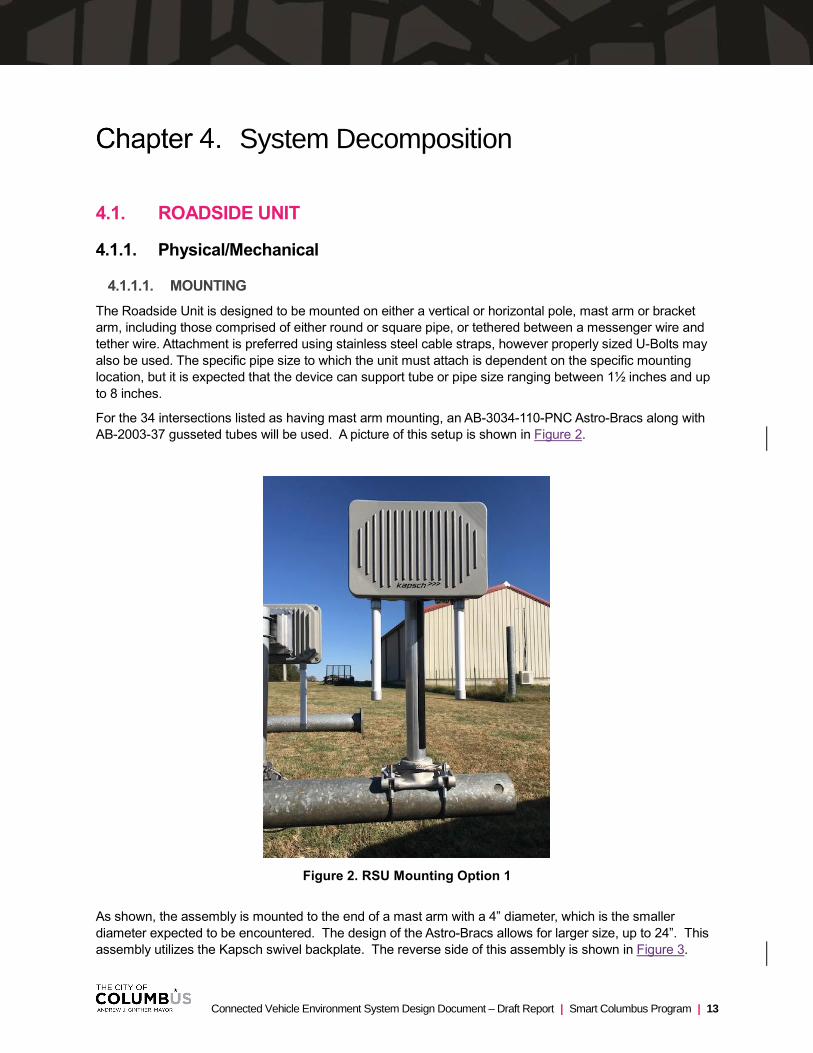
For the 34 intersections listed as having mast arm mounting, an AB-3034-110-PNC Astro-Bracs along with
AB-2003-37 gusseted tubes will be used. A picture of this setup is shown in Figure 2.
Figure 2. RSU Mounting Option 1
As shown, the assembly is mounted to the end of a mast arm with a 4” diameter, which is the smaller
diameter expected to be encountered. The design of the Astro-Bracs allows for larger size, up to 24”. This
assembly utilizes the Kapsch swivel backplate. The reverse side of this assembly is shown in Figure 3.

Chapter 4. System Decomposition
14 | Smart Columbus Program | Connected Vehicle Environment System Design Document – Draft Report
Figure 3. Reverse View Option 1 RSU Mounting
For the eight (8) installations on either a horizontal or vertical bracket arm, an AS-3009-120-PNC Astro-
Bracs paired with the AB-0390-74 gusseted tube will be used. This assembly also uses the Kapsch swivel
backplate. A picture of this setup is shown in Figure 4.
Figure 4. RSU Mount Option 2
A side view of both mounting options, 1 & 2 is shown in Figure 5.

Chapter 4. System Decomposition
Connected Vehicle Environment System Design Document – Draft Report | Smart Columbus Program | 15
Figure 5. Side View RSU Mounting Options 1 & 2
For the 22 locations listed as mounting on bracket arms, the Kapsch swivel backplate is sufficient as it
allows U-bolt mounting to 1.5” and 2” pipe.
4.1.1.2. POWER
The RSU shall support an IEEE 802.3at-2009 Power-over-Ethernet (PoE) interface, not to exceed 25 Watts.
The vendor shall supply the necessary PoE injector to be installed in the controller cabinet where access to
115/15A power will be available. The PoE injector does not need to be weatherproof but must be capable of
operations in an extended temperature and humidity range -40 to 140 degrees Fahrenheit, and 10 to 90%
relative humidity.
4.1.1.3. CONNECTIONS
The RSU shall support at a minimum, the following electrical connections:
• 1 RJ-45 Weatherproof Ethernet (PoE-capable)
• 2 N-Type Female DSRC Connectors
• GNSS (varies) – Typically SMA
1. The Danlaw RSU has an integral GNSS antenna and does not have an external connector
4.1.1.4. ANTENNA
The RSU will, at a minimum, includes two DSRC radios and corresponding antenna and a single GNSS
antenna.
• DSRC: 2 Omni-directional 6dBi, 5.9 GHz antenna with N-Type female connector
Chapter 4. System Decomposition
16 | Smart Columbus Program | Connected Vehicle Environment System Design Document – Draft Report
• GNSS: 1575 MHz, 50 Ohm, 14 dB Active GPS Antenna
4.1.2. Firmware
4.1.2.1. DEVICE CONFIGURATION
The RSU System Integrator Team will configure each Roadside Unit prior to being deployed. This minimizes the Electrical Contractor’s effort at the time of installation.
The following items will be configured on each RSU:
• IPv4 Network Address
• IPv6 Network Address
• IPv6 DSRC Radio Address
• Smart Columbus Operating System SNMP Server IPv4 Address
• Messages
SPaT
MAP
RSM
SRM
SSM
• WSAs
PSIDs
WAVE Routing Advertisement (WRA)
Kapsch Units
For Kapsch units all Ethernet configurations are managed by using SSH to access the device and update
the EEPROM settings using provided scripts. Once the setting has been applied the unit needs to be
rebooted for them to take effect. See the User’s Manual for specific details.
IPv6 radio information, store and repeat messages (MAP, RSM), WSA services, WRA and SNMP endpoints
are configured using SNMP and the MIB specified by USDOT RSU 4.1.
SPaT messages are generated when the device has a valid store and repeat MAP configured and a valid
traffic controller configuration. The traffic controller configuration is set up using Kapsch’s Connected
Mobility Control Center (CMCC). See the User’s Manual for specific details.
Signal preemption and priority, including the processing of SRM messages and the response SSM
messages, is set up by using the correct permissions for security certificates and using the following
configurations described above:
• Traffic controller
• WSA services with the appropriate PSIDs

Chapter 4. System Decomposition
Connected Vehicle Environment System Design Document – Draft Report | Smart Columbus Program | 17
Danlaw Units
For Danlaw units, all ethernet configurations are managed by using SSH to access the device and update
the configuration files settings using a text editor as well as SNMP. Once the settings have been applied,
the unit needs to be rebooted for them to take effect. See the Danlaw RSU User’s Manual for specific
details.
IPv6 radio information, store and repeat messages (MAP, RSM), WSA services, WRA and SNMP endpoints
are configured using SNMP and the MIB specified by USDOT RSU 4.1.
SPAT messages are generated when the device has a valid store and repeat MAP configured and a valid
traffic controller configuration. The traffic controller configuration is set up using. See the Danlaw RSU
User’s Manual for specific details.
Signal preemption and priority, including the processing of SRM messages and the response SSM
messages, is set up by using the correct permissions for security certificates.
Siemens Units
For Siemens RSU WSA/WRA, SPAT_MAP, and TSP are configured via WebUI or XFER (open websocket)
interface. Siemens RSU does not require a reboot for configuration changes.
4.1.2.1.1 SCMS Enrollment
Each RSU manufacturer will define a secure process for configuring and equipping the units with the
necessary security credentials. Each unit will go through a secure enrollment process with the SCMS.
Kapsch Units
To enroll a Kapsch RSU to use SCMS certificates the following steps are used:
• Use SSH to log into the script.
• Enable the HSM on the unit.
• Run the enrollment script to generate the enrollment file that will be processed by the SCMS
system.
• Process the enrollment with the SCMS and collected the enrollment response.
• Transfer the enrollment response file back to the unit.
• Run the enrollment response script to process it.
• When the device SW runs again it will start the certificate generation and download process when
the network is deemed available.
See the User’s Manual for specific details.
Danlaw Units
Devices are normally enrolled at Danlaw and certificates obtained in the field. We can share the process
used however the enroller will need to make their own arrangements with ISS.
For Danlaw units, the first step is to create an enrollment certificate request using a utility provided by
OnBoardSecurity and send it to the SCMS server. When the server sends back the enrollment certificate
response package, the second step is to process it with a different utility, also provided by OnBoardSecurity.
All processed enrollment certificates, private keys, RA and MA certificates, etc., are stored in a subdirectory
by the utility at the end of the bootstrapping.

Chapter 4. System Decomposition
18 | Smart Columbus Program | Connected Vehicle Environment System Design Document – Draft Report
Once this is complete, the security global configuration file is modified to always download the top off
certificates from the SCMS server.
By default, the SCMS client will download 20 weeks of certificates to the system during the initial certificate
download process. Later, when some certificates become expired, the client will automatically start
downloading topping off certificates when the number (in weeks) of unexpired certificates is less than 10,
until there are 20 weeks of valid certificates on the system.
These settings may be overridden by creating a default.policy file with proper values for the top off threshold
and the full threshold.
Siemens Units
Siemens RSUs will be delivered enrolled. Columbus has to provide appropriate certificate instructions in the well-known format used by Omniair and CV pilots.
The RSU System Integrator will configure each RSU using the appropriate setup processes including
generating the enrollment keys, submitting the enrollment keys to the SCMS, retrieving the initial certificates,
and loading the initial certifications on the unit. Once deployed, the RSU security modules will automatically
connect to the SCMS to request application certificates.
RSUs can update security certificates automatically, without operator intervention.
Once a device is configured, a backup of all configuration parameters/files is saved on a Path Master server
for reference and/or in the event of a hardware failure the replacement device can be configured the same
as the original. Note: This does not include security certificates as the keys are stored in the hardware
security module and are not transferrable. A replacement RSU will be required to be enrolled separately
with SCMS.
The RSU System Integrator will deliver configured RSUs to the City for installation.
4.1.2.2. CERTIFICATE TOP-OFF
RSUs will maintain two weeks’ worth of certificates for each application; this week and next week. On the last day of the current week (based on enrollment date), RSUs will request certificates for the following week; always maintaining two weeks’ worth of certificates on board.
RSUs can update security certificates automatically, without operator intervention.
4.1.2.3. REMOTE UPDATES
The RSU firmware can be updated from the operation center by center personnel which includes both TMC operators and the System Integrator. Updates are applied after the firmware has gone through testing and approved by the City. This will minimize deploying firmware updates that do not resolve an identified issue or cause unintended issues. The RSU firmware update process and procedures will be defined in the Smart Columbus CVE Operation and Maintenance Document (to be developed later)
4.1.2.4. MISBEHAVIOR DETECTION
If available, RSUs will download Certificate Revocation Lists (CRL) on a weekly basis. CRLs are utilized to reject messages from bad actors and prevent compromised devices from broadcasting bad data. If the RSU detects it is on the CRL, the RSU will not broadcast WSAs, SPaT, MAP, or other messages. This ensures the RSU does not continue to broadcast invalid messages.
Chapter 4. System Decomposition
Connected Vehicle Environment System Design Document – Draft Report | Smart Columbus Program | 19
4.1.2.5. LOCATION SERVICES AND TIME SYNCHRONIZATION
All RSUs have a GNSS receiver to obtain position and time. RSU position is required for security, to ensure
the device has not been moved from its installation location. GNSS time is utilized to set and maintain
device “System Time”. System Time is required for security, channel switching synchronization, and
application synchronization
4.1.2.6. EVENT LOGGING
RSUs can be configured to log system events, errors, or other anomalies. This helps Operations and Maintenance troubleshoot the device/system when irregularities occur.
Kapsch Units
Some logging can be configured through SNMP and other logging can be configured by using an SSH or SCP session to edit files on the device. See the User’s Manual for specific details.
Danlaw Units
DSRC stack software event logs as well as Linux operating system log files are available and are found in separate directories.
Additional details related to event logging and log levels are available. See the Danlaw User’s Manual for specific details
Siemens Units
Siemens RSU allows configuration of logging via web UI. Logs can be downloaded via web UI, as well
4.1.2.7. BUILT-IN SELF-TEST
Upon boot up, RSUs perform a self-check to ensure all subsystems within the device are operational. If one or more subsystems are not operational, the RSU will set an error in the appropriate SNMP Object Identifier (OID) to inform the operations staff. The CMCC/TMC will provide real-time monitoring and alerts should issues arise. Notifications will be configured to be sent by text and/or e-mail to appropriate members of both the Kapsch and Smart Columbus teams. Once an issue has been investigated, Kapsch will supply the required documentation and take appropriate actions to address the issue.
4.1.2.8. MESSAGE FORWARDING
RSUs will forward messages to remote hosts for processing, further distribution, and archival. Message forwarding is in accordance with USDOT DSRC RSU Specification 4.1a and shall be performed over SNMP. The following parameters are configured on each RSU for each message:
• BSM
Smart Columbus Operating System IP Address (for archive and distribution)
PSID 0x20
• SPaT
Smart Columbus Operating System IP Address (for archive and distribution)
PSID 0x82
• SRM
Smart Columbus Operating System IP Address (for archive and distribution)
PSID 0x20-40-96
Chapter 4. System Decomposition
20 | Smart Columbus Program | Connected Vehicle Environment System Design Document – Draft Report
• SRM
Message Handler IP Address (for processing and placing a priority call to the Signal Controller)
PSID 0x20-40-96
4.1.3. System Monitoring
RSUs will be monitored by the Kapsch CMCC, which provides a robust system for managing the City’s
connected assets. CMCC’s architecture is flexible, allowing a variety of external connections and
configurations, meeting the Smart Columbus CV TMC requirements. CMSS functionality includes:
• Asset Management: Each location and its associated equipment can be defined, and information
maintained. Most configurations are set at the location level, rather than the device level. This allows
equipment to be swapped out quickly and easily with minimal setup required.
• MAP Generation: CMCC includes the ability to build MAP messages via an intuitive graphical user
interface directly on a MAP view of the intersection or road segment.
• RSM Message Generation: CMCC includes functionality for building and distributing RSMs
• Message Definition and Scheduling: RSU messages can be created and configured via robust
scheduling. This includes the ability to set specific times, days of the week, and intervals in which
messages will be transmitted. Messages and message scheduling can be easily updated and sent to
the RSUs.
• Data Management: Real-time traffic information can be monitored at each location. This includes
traffic signal phasing and all communication between RSUs, OBUs, and pedestrians.
• Automated Monitoring and Alert: Dashboards and statuses provide the ability to monitor all
devices within the network to detect any issues in connectivity or messaging. Designated TMC
personnel will register for alerts and notifications when issues arise with equipment, system functions,
or recorded data.
Kapsch units can connect using the native protocol by using SSH or SCP to modify configuration files on the unit. For Siemens and Danlaw RSUs, the Kapsch RCU software running in the Econolite Coprocessor will be able to send configuration information to the RSUs via SNMP. The RCU is the Message Handler.
Siemens RSU supports SNMP per USDOT v4.1 spec. Additional a custom websocket API can be used.
4.1.4. Message Handler
Each intersection will have a Message Handler to encode/decode J2735 messages for use with remote
hosts (Signal Controller, Smart Columbus Operating System, etc.). The message handler is expected to be
hosted on the CV Co-Processor board located in the Econolite Controller. For the Kapsch RSUs, this
function can be performed on the RSU itself.
4.1.4.1. POSITION CORRECTION
The Message Handler will receive Networked Transport of Radio Technical Commission for Maritime
(RTCM) via Internet Protocol (NTRIP) RTCM messages, wrap the RCTM messages with a SAE V2X
Message Header, and send the SAE J2735-032016 RTCM messages to the RSU for broadcast as
Immediate Forward Messages.

Chapter 4. System Decomposition
Connected Vehicle Environment System Design Document – Draft Report | Smart Columbus Program | 21
4.1.4.2. SIGNAL REQUEST MESSAGES
The Message Handler decodes Signal Request Messages (SRM) received from RSUs and sends a priority
call to the Signal Controller. If the Signal Controller receives multiple priority requests simultaneously, it will
determine the order of all requests based on the following criteria:
• Transit / Freight
Direction of Travel
Time to intersection
• First Responders
Time to intersection
Pre-empt requests for a different approach than a prior signal priority request will take precedence.
4.1.4.3. SIGNAL STATUS MESSAGES
The Message Handler encodes Signal Status Messages (SSM) based on data received from the Signal
Controller. Data includes Request ID currently being served, intersection ID, and request ID’s currently in
queue.
4.1.5. Service Channel Plan
Each RSU is assigned a Service Channel based on an overall system wide Service Channel Plan. A Service
Channel plan minimizes channel overlap at neighboring RSUs, which maximizes the number of vehicles
that can communicate with back office services simultaneously.
Channels 172 will be used for continuous broadcast of safety-related messages including BSM, SPaT, MAP
and RTCM. Channel 178 will broadcast the Wave Service Advertisement (WSA) and RSM. Depending on
specific location and using a pattern that does not allow for adjacent RSUs to use the same service channel,
the third channel used on an RSU will be one of either 174, 176 or 180.
4.2. ONBOARD UNIT
4.2.1. Physical/Mechanical
4.2.1.1. MOUNTING
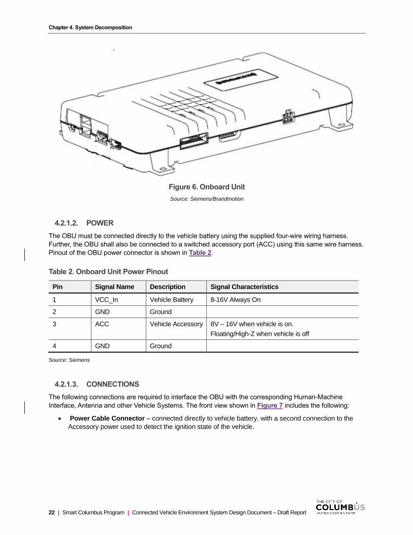
The OBU measures 8.15” x 5.4” x 1.26” and weighs 432 grams. The OBU case includes four (4) mounting
tabs that accommodate #8 screws. See Figure 6. Mounting locations for the OBU within the vehicle may
vary depending on vehicle type but is primarily expected to be mounted as an under-dash unit, using nylon
wire-ties. Other potential mounting locations include the trunk, under a seat, glove box, or in the case of
equipped transit vehicles, the accessory rack. The location shall be inconspicuous to driver, passengers and
persons outside of the vehicle. Further, the OBU shall be mounted in a manner that will allow for the vehicle
to be returned to its original, pre-installation condition. Use of wire ties, hook and loop tape (Velcro),
removable clips or other non-permanent means shall be permitted. Use of existing holes to facilitate
mounting is permissible so long as the use of said holes does not prevent their original purpose from being
satisfied. Attaching to existing wire bundles is not ideal but is permissible if the bundle itself is secured by a
wire-tire or clip and the strain/weight of the wire is not directly imposed on the electrical connector. If
mounted under dash or under the seat, the unit shall be installed on the passenger side such that a
dislodged unit will not interfere with the operator’s ability to operate the vehicle.
Chapter 4. System Decomposition
22 | Smart Columbus Program | Connected Vehicle Environment System Design Document – Draft Report
Figure 6. Onboard Unit
Source: Siemens/Brandmotion
4.2.1.2. POWER
The OBU must be connected directly to the vehicle battery using the supplied four-wire wiring harness.
Further, the OBU shall also be connected to a switched accessory port (ACC) using this same wire harness.
Pinout of the OBU power connector is shown in Table 2.
Table 2. Onboard Unit Power Pinout
Pin Signal Name Description Signal Characteristics
1 VCC_In Vehicle Battery 8-16V Always On
2 GND Ground
3 ACC Vehicle Accessory 8V – 16V when vehicle is on.
Floating/High-Z when vehicle is off
4 GND Ground
Source: Siemens
4.2.1.3. CONNECTIONS
The following connections are required to interface the OBU with the corresponding Human-Machine
Interface, Antenna and other Vehicle Systems. The front view shown in Figure 7 includes the following:
• Power Cable Connector – connected directly to vehicle battery, with a second connection to the
Accessory power used to detect the ignition state of the vehicle.

Chapter 4. System Decomposition
Connected Vehicle Environment System Design Document – Draft Report | Smart Columbus Program | 23
Figure 7. Front View of Electrical Connectors
Source: Siemens/Brandmotion
Additional Connections shown on the side and rear (see Figure 8) of the unit include:
• HDMI– video signal for touchscreen monitor
• Touchscreen Interface – Control and power for touchscreen monitor
• Dual USB– Power and control of external devices
• USB Mini-B– for system debug and configuration
• Antenna Connector – Automotive Ethernet communication with Antenna.
Figure 8. Rear View of Electrical Connectors
Source: Siemens/Brandmotion

Chapter 4. System Decomposition
24 | Smart Columbus Program | Connected Vehicle Environment System Design Document – Draft Report
4.2.1.4. HUMAN MACHINE INTERFACE
A 4-inch Heads-Up Display (HUD) is the selected solution for a Human Machine Interface (HMI).
This full-featured displays offer a high-resolution, full-color capability with automatic variable brightness
setting and visible in all expected lighting conditions The Heads-Up display will be mounted to the
dashboard using hook-and-loop tape, or other double-sided tape, in a manner that will be visible to the
driver but not obstruct their view of the road or any critical displays in the vehicle. The HUD is expected to
interface to the OBU via the 3.5mm audio jack and the HDMI. Further, the HUD will require a separate
power connection to a switched source such as that provided by the vehicle accessory port (ACC). Power
draw from the HUD is not expected to exceed 2A continuous and is rated for <50mA in the key off position.
4.2.1.5. ANTENNA (AE)
The Digital Antenna includes a Satellite (SDARS) receiver module, a GNSS receiver module and a dual-
channel DSRC transceiver module all in a single, weather-proof externally mounted magnetic unit. The
dimensions of the Digital Antenna are: 120mm x 90mm x 36mm. The weight is 440 grams. A single thin
(Ø2.3mm) Unshielded Twisted Pair (UTP) Automotive Ethernet cable extends from the antenna a length of
22 feet for light vehicles and 44 feet for use in trucks, buses and fire apparatus. The use of a digital antenna
allows for most of the processing to occur directly in the antenna, reducing the cable size necessary to
interface the antenna with the OBU to a minimal size.
Figure 10. Digital Antenna
Source: Siemens/Brandmotion
4.2.1.6. WIRING
The following figures show examples of antenna cable routing that may be used in various vehicle types. As
with the OBU mounting, all wiring shall be reversible.
Image of HUD not yet available.
Figure 9. Heads-Up Display

Chapter 4. System Decomposition
Connected Vehicle Environment System Design Document – Draft Report | Smart Columbus Program | 25
Figure 11. Wire Routing Example – Light-Duty Vehicle
Source: Siemens/Brandmotion
Figure 12. Wire Routing Example – Sport Utility Vehicle
Source: Siemens/Brandmotion
Figure 13. Wire Routing Example – Light-Duty Pickup Truck
Source: Siemens/Brandmotion

Chapter 4. System Decomposition
26 | Smart Columbus Program | Connected Vehicle Environment System Design Document – Draft Report
4.2.1.7. SIERRA MODEM INTERFACE – TRANSIT ONLY
OBUs installed in revenue service transit vehicles shall be interface with the existing Sierra wireless modem
via a fixed Ethernet connection.
4.2.2. Firmware
4.2.2.1. DEVICE CONFIGURATION
In the OBU System Integrator team, Siemens will configure each Siemens On-Board Unit (OBU) prior to providing it to BrandMotion for vehicle installation. This minimizes the installation shops effort at the time of installation.
The following items will be configured on each OBU:
• IPv4 Network Address (if applicable)
• Antenna Offsets and application presets
• Enrollment in SCMS
• TLS client authentication certificate for vendor server Antenna offset and application presets will be configured upon installation using the Configuration tool. OBU connects to the Configuration tool via Wi-Fi. IP address is assigned during the Wi-Fi connection process. Siemens OBUs will come with app presets pre-configured.
4.2.2.1.1 SCMS Enrollment
Siemens On-Board Unit (OBU) require a secure process to configure and equip the device with the necessary security credentials to successfully operate in the Smart Columbus system. Each unit will go through a secure enrollment process with the SCMS.
Smart Columbus will provide list of PSID / SSP combinations to enroll the OBUs to Siemens. Siemens will configure each OBU using the appropriate setup processes including generating the enrollment keys, submitting the enrollment keys to the SCMS, retrieving the initial certificates, and loading the initial certifications on the unit. Once the OBU is enrolled in the SCMS, the OBU security modules will automatically connect to the SCMS to request 1 year of pseudonym certificates.
OBUs update security certificates automatically, without operator intervention.
Once a device is configured, a backup of all configuration parameters/files is saved on a Siemens server for reference and/or in the event of a hardware failure the replacement device can be configured the same as the original.
The OBU Integrator will deliver configured OBUs for installation.
4.2.2.2. CERTIFICATE TOP-OFF
To the extent possible, each OBU will maintain one years’ worth of pseudonym certificates. When in communication range of an RSU on, or after, the last day of the current week, an OBU will request certificates for the following week(s) to always maintain three years’ worth of certificates on board.
OBUs update security certificates automatically, without operator intervention.
4.2.2.3. THREAT DETECTION
Threat Detection is based on the algorithm used for the IMA, RLVW and FCW applications.

Chapter 4. System Decomposition
Connected Vehicle Environment System Design Document – Draft Report | Smart Columbus Program | 27
4.2.2.4. THREAT ARBITRATOR
Approach to Threat Arbitration is still under design
4.2.2.5. OVER-THE-AIR (OTA) UPDATES
OBUs will utilize an RSU’s IPv6 service to connect to a designated server to determine its firmware updates or patches are available for download. If firmware updates are available, the OBU will download and store the required files. The OBU will download the OTA update files from a vendor-provided secure internet host. The OBU verifies authenticity of the downloaded OTA update files. Valid update files will be installed upon the next power up. On vehicles with HUD a version string could be displayed upon power up.
4.2.2.6. MISBEHAVIOR DETECTION
If available, OBUs will download Certificate Revocation Lists (CRL) on a weekly basis. CRLs are utilized by OBUs to reject messages from bad actors and prevent compromised devices from broadcasting bad data. If the OBU detects it is on the CRL, the OBU will not broadcast BSM or other messages to ensure the OBU does not continue to broadcast invalid messages. The device will generate a system log noting the date and time the device determined it was on the CRL.
4.2.2.7. LOCATION SERVICES AND TIME SYNCHRONIZATION
All OBUs have a GNSS receiver to obtain position and time. OBU position is required for proper application performance and security. GNSS time is utilized to set and maintain device “System Time”. System Time is required for security, channel switching synchronization, and application synchronization.
4.2.2.8. POSITION CORRECTION
OBUs will utilize corrections data available via satellite. SAE J2735-032016 RTCM messages will still be broadcast from RSUs. Note that the OBUs deployed by the OBU Integrator will also receive position corrections data via satellite to support its operations.
The OBU supports RTCM v2.3 messages of type 1, 2, 3, and 9.
4.2.2.9. EVENT LOGGING
Transit OBUs log the following event types
• OS/General System Events
• Driver Alert Event
Transit Vehicle OBUs also log transmitted and received BSMs.
Transit Vehicle OBUs have 4 GB of Storage to maintain 2 days’ worth of log files.
4.2.2.10. LOG OFFLOADING
When a Transit Vehicle returns to the Maintenance garage after a shift, the OBU offloads its TVIER logs
using the data log upload service of the local Wi-Fi access points. The logs are forwarded to a backend
server for processing. .The data logs are utilized by the COTA Fleet Manager to monitor the operation of the
device. Once logfiles are offloaded to COTA, they are deleted from the OBU.
<<<List specific log file configuration parameters for the Siemens OBU. Additional details will be available and provided after the OBU System Integrator NTP which is anticipated in July 2019.>>>

Chapter 4. System Decomposition
28 | Smart Columbus Program | Connected Vehicle Environment System Design Document – Draft Report
4.2.2.11. BUILT-IN SELF-TEST
Upon bootup, OBUs perform a self-check to ensure all subsystems within the device are operational. If one or more subsystems are not operational, the OBU will write entry in its system log file.
4.2.2.12. TAMPER DETECTION
The OBUs provide a tamper detection label as a visual indication the device has been opened as well as a system logfile entry when a compromise is detected. The OBU will erase all keys and pseudonym certificates if a compromise of the Hardware Security Module (HSM) is detected.
The OBU’s main goal in threat detection and response is to protect the enrollment keys inside the HSM. As such the HSM chip will detect physical tampering via its active shielding. A tamper event detected by the active shield places the HSM permanently into the “Tamper is detected” error state. The OBUs with HUD will indicate a critical error status. The status of the OBUs without HMI will be monitored via data upload.
Also, the HSM will go into a permanent error state upon detection of tampering with the HSM. In this error state the HSM will refuse to perform any cryptographic operations. Private keys cannot be read / extracted from the HSM in any case.
4.2.2.13. HMI OUTPUT
Light Duty and Emergency vehicle OBUs contain a Human Machine Interface (HMI) to alert drivers to potential threats from other connected vehicles in their vicinity.
Light Duty vehicle OBUs will provide driver alerts for the following applications:
• Emergency Electronic Brake Light Warning
• Forward Collision Warning
• Intersection Movement Assist
• Lane Change Warning / Blind Spot Warning
• Red Light Violation Warning
• Reduced Speed School Zone
First Responder vehicle OBUs will provide driver alerts for the following applications:
• Emergency Vehicle Preemption
Chapter 4. System Decomposition
Connected Vehicle Environment System Design Document – Draft Report | Smart Columbus Program | 29
4.3. TRAFFIC SIGNAL CONTROLLER / SIGNAL CABINET
A total of 85 signalized intersections will be equipped with the necessary Roadside Units and support
equipment to enable the CVE. The majority of these intersections are owned and operated by the City of
Columbus. However, Franklin County owns and operates a group of intersections, along both Cleveland
Avenue and Alum Creek Drive while Ohio DOT District 6 is the owner/operator of three intersections on
Alum Creek Drive. All intersections are presently or will be connected to the Columbus Traffic Signal System
(CTSS) at the time of go-live for the CVE. Physical/Mechanical
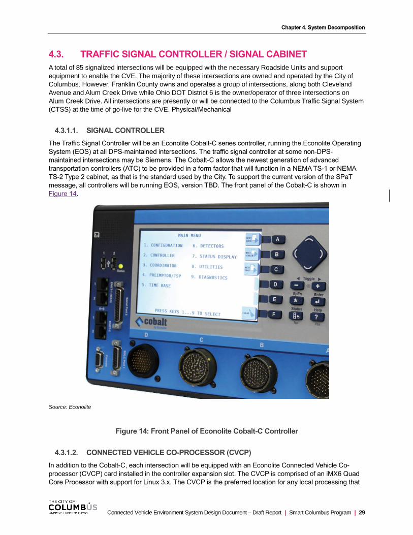
4.3.1.1. SIGNAL CONTROLLER
The Traffic Signal Controller will be an Econolite Cobalt-C series controller, running the Econolite Operating
System (EOS) at all DPS-maintained intersections. The traffic signal controller at some non-DPS-
maintained intersections may be Siemens. The Cobalt-C allows the newest generation of advanced
transportation controllers (ATC) to be provided in a form factor that will function in a NEMA TS-1 or NEMA
TS-2 Type 2 cabinet, as that is the standard used by the City. To support the current version of the SPaT
message, all controllers will be running EOS, version TBD. The front panel of the Cobalt-C is shown in
Figure 14.
Source: Econolite
Figure 14: Front Panel of Econolite Cobalt-C Controller
4.3.1.2. CONNECTED VEHICLE CO-PROCESSOR (CVCP)
In addition to the Cobalt-C, each intersection will be equipped with an Econolite Connected Vehicle Co-
processor (CVCP) card installed in the controller expansion slot. The CVCP is comprised of an iMX6 Quad
Core Processor with support for Linux 3.x. The CVCP is the preferred location for any local processing that

Chapter 4. System Decomposition
30 | Smart Columbus Program | Connected Vehicle Environment System Design Document – Draft Report
may be necessary at the intersection. Figure 15 shows the CVCP card installed in the Cobalt-C controller.
Figure 16 describes the interface to the controller. The CVCP, when equipped with an external 48VDC
supply may be used as the PoE+ for the RSU.
Source: Econolite
Figure 15: Econolite Cobalt Controller with CVCP Card Installed

Chapter 4. System Decomposition
Connected Vehicle Environment System Design Document – Draft Report | Smart Columbus Program | 31
Source: Econolite
Figure 16: Econolite CVCP Front Connectors
4.3.1.3. DOOR OPEN SWITCH
All signal cabinets that are part of the CVE will be equipped with a door switch that will notify staff at the City
TMC when a door is opened. The switch will not affect signal timing operations, inhibit work necessary to be
performed by maintenance personnel, or affect the CVE. This feature will enable operations staff to
corroborate any detected activities with maintenance staff ensuring that no unauthorized access to the CVE
occurs. Every controller cabinet and node cabinet in the project will be equipped with City of Columbus
padlocks, which will provide the first layer of physical security.
4.3.2. Signal Operations
4.3.2.1. TIMING PLANS
The City of Columbus maintains a library of signal timing plans associated with each intersection. Timing
plans, including time-of-day restrictions shall be made available to the RSU and OBU vendors, as
appropriate, as part of the design activity. Public disclosure of these plans is not common practice. These
are critical for device configuration particularly for creating signal groups and phase-to-lane movement
mapping.
Chapter 4. System Decomposition
32 | Smart Columbus Program | Connected Vehicle Environment System Design Document – Draft Report
4.3.2.2. PREEMPT RULES
Presently, Emergency Vehicle Preempt will be available at all CV-equipped intersections to equipped fire
and police responders. Signal preemption allows emergency vehicles to disrupt the normal signal cycle in
order to proceed through the intersection more quickly and under safer conditions. The preemption systems
can extend the green on an emergency vehicle’s approach or replace the phases and timing for the whole
cycle or put the signal on all red state dependent on the preference from Fire and Police. The Manual on
Uniform Traffic Control Devices discusses signal preemption, standards for the phases during preemption,
and priorities for different vehicle types that might have preemption capabilities. For Smart Columbus, the
expectation is to extend the green phase, or as available, advance to the green phase so as to maximize
the ability to flush the queue ahead of the emergency vehicle. This is true regardless of the approach,
primary or secondary. The deployed system needs to work along with the existing GTT system along the
Cleveland Avenue Corridor. This means that it would need to interface with the existing system or the traffic
signal would have to handle requests from multiple systems.
Emergency Vehicles OBUs will only request preemption when the siren is active but will initiate request
activities as soon as it is in radio-range of the RSU. No driver interaction is necessary to initiate the request,
which will be enabled using the SRM message.
No special hardware outside of that already described for the CVE will be required. Preempt calls to the
signal controller are expected to be made using NTCIP 1202 Set statements.
4.3.2.3. PRIORITY RULES
Signal priority will be available to both transit and freight vehicles but only at select CV-equipped
intersections. Those which are expected to support signal priority, and the specific type (transit or freight) are
listed in Appendix D. Currently, the transit priority-enabled intersections is limited to COTA’s C-MAX BRT
service along Cleveland Avenue, between Second Avenue and SR-161 / Dublin-Granville Road. Priority for
transit vehicles for the CVE will be limited to C-MAX service from Second Avenue to Morse Road. Freight
signal priority (FSP) will be enabled at signalized intersections along Alum Creek Drive (between I-270
interchange and SR-317 London-Groveport Road) and Morse Road (between I-270 interchange and Stygler
Road).
No special hardware outside of that already described for the CVE will be required. Priority calls to the signal
controller are expected to be made using NTCIP 1211 commands. When initially deployed, the Transit
Signal Priority (TSP) applications will not directly affect timing operations, but instead, simply be logged and
compared with the existing GTT system performance. On the other hand, FSP will be enabled and support
both early and extended green depending on the specific intersection timing plan. The approach for each
priority-intersection is also annotated in Appendix D.
4.3.2.4. SIGNAL PHASE AND TIMING MESSAGE OUTPUT
The necessary J2735:201603 Signal Phase and Timing (SPaT) message will be produced by the traffic
signal controller and transmitted to the RSU (and other locations) using the IP address(es) configured in the
signal controller.
4.3.2.5. SSM OUTPUT
The traffic signal controller will be capable of providing status of all preempt and priority requests that are
currently pending or being serviced upon the request of the roadside equipment.

Chapter 4. System Decomposition
Connected Vehicle Environment System Design Document – Draft Report | Smart Columbus Program | 33
4.4. NETWORK DESIGN
The Smart Columbus High-Level Network Design is shown in Figure 17. This illustration depicts the existing
CTSS approach whereby a field-hardened Layer 2 switch is installed in each Signal Cabinet and
interconnected, via fiber, to a Communications Node which is comprised of a Layer 3 switch capable of
operating in an extended temperature and humidity range. Approximately ten signal cabinets are interfaced
with a single communications node. The Layer 2 switch is also connected directly to the traffic signal
controller via Ethernet. All of the Communications Nodes are then connected to a Layer 3 switch which
resides at the City’s TMC, where Centracs, the signal system management software system used by the
City, is also hosted. This network is then connected to the City’s existing Metronet. All devices on CTSS are
IPv4 based.
The CVE Network essentially replicates the CTSS by installing Layer 2 switches (minimum of 2 Ethernet
ports) in each signal cabinet and Layer 3 switches (12 ports at a minimum) in the Communications Nodes.
Also, like CTSS, these Layer 3 switches are all then interconnected by a Layer 3 switch housed at the TMC.
The RSU Management software is then expected to be interconnected to this same switch. Finally, a new
firewall, that isolates the CVE Network from the Public Internet will be employed.
Unlike CTSS however, the CVE Network carries both IPv4 and IPv6 traffic. Figure 17 shows the nature
(public/private) of the IPv4 and IPv6 address space.
The CVE will connect with at least four (4) external sources via the public internet. These include the Smart
Columbus Operating System, the ISS Certificate Authority, the a Continuously Operating Reference Station,
and the OBU Vendor Over-the-Air update service.
4.4.1. IP Allocation:
/48 IPv6 prefix provider assigned
/27 IPv4 subnet if possible. Can make do with a /28 if necessary.
4.4.2. Circuit Type/Speed:
Dedicated internet over Ethernet services (Symmetrical upload/download)
Speed- 20-50MB to start. Logical provisioning for future bandwidth upgrades.

Chapter 4. System Decomposition
34 | Smart Columbus Program | Connected Vehicle Environment System Design Document – Draft Report
MetroNET
CTSS
CVE Network Roadside Unit
ISS Cert. Auth
Smart Columbus Operating System
Position CorrectionSystem
VendorOTA Server
Signal CabinetPublic Internet
CommunicationsNode
RSU Mgmt.System
City of Columbus
CTSS
New InternetProvider Link New CVE FW
Existing Metronet ASA5515
Layer 3
Layer 3
CTS
S
Layer 3 Layer 2 SignalController
Layer 2Layer 3 PoE
Signal ControlSystem
PrivateIPv4 Address
PublicIPv4 Address
PublicIPv6 Address
Private IPv4 Address
Public IPv6 Address
Private IPv4 AddressPublic IPv6 Address
Private IPv4 Address
Public IPv6 Address
Private IPv4
AddressPublic IPv6
Address
Private IPv4
AddressPublic IPv6
Address
Private IPv4 Address
Public IPv6 Address
Private IPv4 Address
Public IPv6 Address
PrivateIPv4 Address
Private IPv4 AddressPublic IPv6 Address
Source: City of Columbus
Figure 17. CVE Hi-Level Network Design
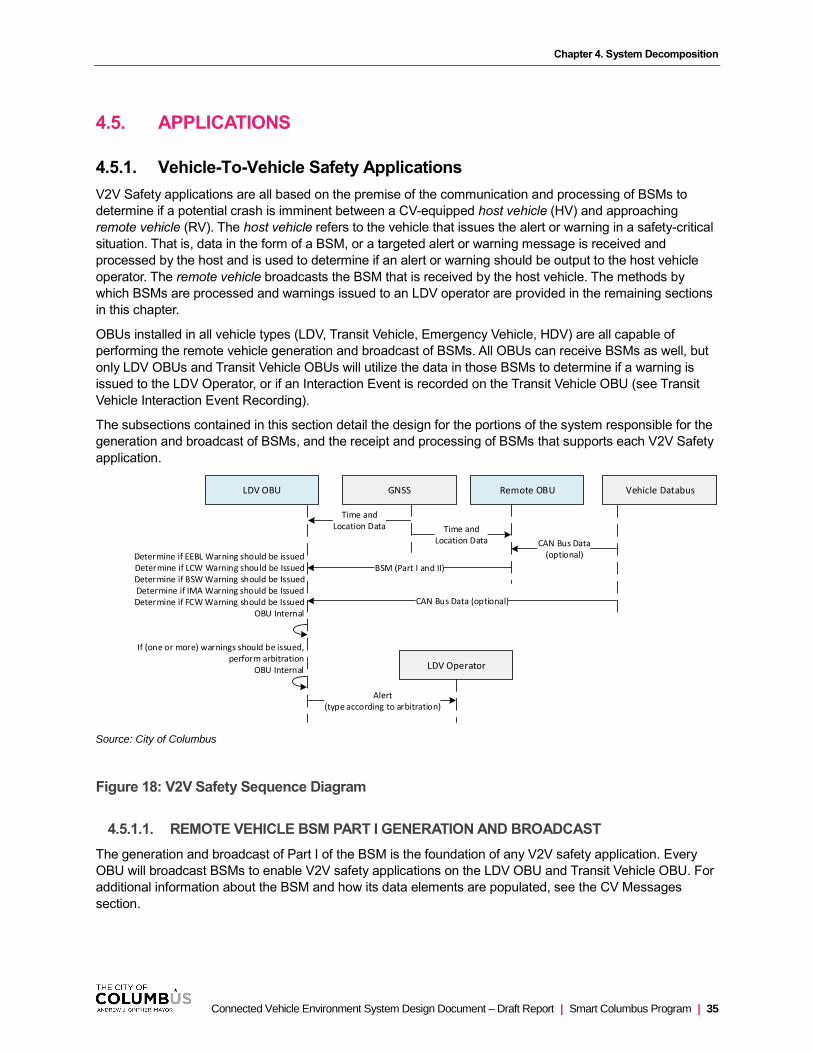
Chapter 4. System Decomposition
Connected Vehicle Environment System Design Document – Draft Report | Smart Columbus Program | 35
4.5. APPLICATIONS
4.5.1. Vehicle-To-Vehicle Safety Applications
V2V Safety applications are all based on the premise of the communication and processing of BSMs to
determine if a potential crash is imminent between a CV-equipped host vehicle (HV) and approaching
remote vehicle (RV). The host vehicle refers to the vehicle that issues the alert or warning in a safety-critical
situation. That is, data in the form of a BSM, or a targeted alert or warning message is received and
processed by the host and is used to determine if an alert or warning should be output to the host vehicle
operator. The remote vehicle broadcasts the BSM that is received by the host vehicle. The methods by
which BSMs are processed and warnings issued to an LDV operator are provided in the remaining sections
in this chapter.
OBUs installed in all vehicle types (LDV, Transit Vehicle, Emergency Vehicle, HDV) are all capable of
performing the remote vehicle generation and broadcast of BSMs. All OBUs can receive BSMs as well, but
only LDV OBUs and Transit Vehicle OBUs will utilize the data in those BSMs to determine if a warning is
issued to the LDV Operator, or if an Interaction Event is recorded on the Transit Vehicle OBU (see Transit
Vehicle Interaction Event Recording).
The subsections contained in this section detail the design for the portions of the system responsible for the
generation and broadcast of BSMs, and the receipt and processing of BSMs that supports each V2V Safety
application.
LDV Operator
Alert(type according to arbitration)
If (one or more) warnings should be issued,perform arbitration
OBU Internal
LDV OBU
Determine if EEBL Warning should be issuedDetermine if LCW Warning should be IssuedDetermine if BSW Warning should be IssuedDetermine if IMA Warning should be IssuedDetermine if FCW Warning should be Issued
OBU Internal
GNSS
Time andLocation Data
Vehicle Databus
CAN Bus Data (optional)
Remote OBU
BSM (Part I and II)
CAN Bus Data(optional)
Time andLocation Data
Source: City of Columbus
Figure 18: V2V Safety Sequence Diagram
4.5.1.1. REMOTE VEHICLE BSM PART I GENERATION AND BROADCAST
The generation and broadcast of Part I of the BSM is the foundation of any V2V safety application. Every
OBU will broadcast BSMs to enable V2V safety applications on the LDV OBU and Transit Vehicle OBU. For
additional information about the BSM and how its data elements are populated, see the CV Messages
section.
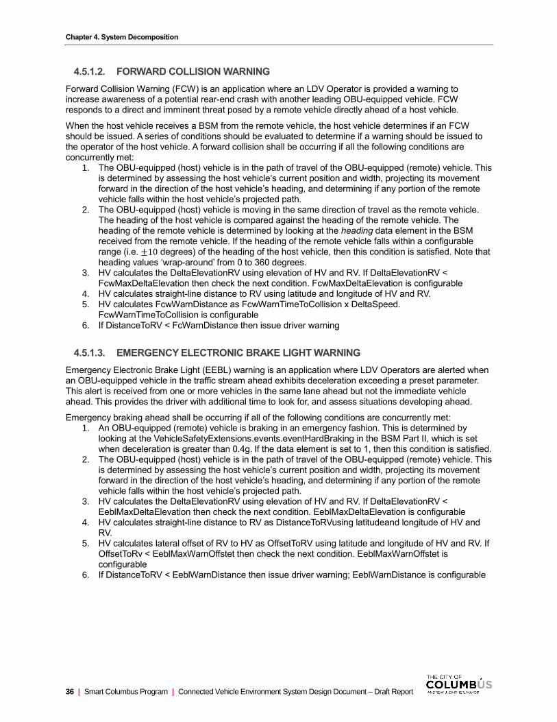
Chapter 4. System Decomposition
36 | Smart Columbus Program | Connected Vehicle Environment System Design Document – Draft Report
4.5.1.2. FORWARD COLLISION WARNING
Forward Collision Warning (FCW) is an application where an LDV Operator is provided a warning to increase awareness of a potential rear-end crash with another leading OBU-equipped vehicle. FCW responds to a direct and imminent threat posed by a remote vehicle directly ahead of a host vehicle.
When the host vehicle receives a BSM from the remote vehicle, the host vehicle determines if an FCW should be issued. A series of conditions should be evaluated to determine if a warning should be issued to the operator of the host vehicle. A forward collision shall be occurring if all the following conditions are concurrently met:
1. The OBU-equipped (host) vehicle is in the path of travel of the OBU-equipped (remote) vehicle. This is determined by assessing the host vehicle’s current position and width, projecting its movement forward in the direction of the host vehicle’s heading, and determining if any portion of the remote vehicle falls within the host vehicle’s projected path.
2. The OBU-equipped (host) vehicle is moving in the same direction of travel as the remote vehicle. The heading of the host vehicle is compared against the heading of the remote vehicle. The heading of the remote vehicle is determined by looking at the heading data element in the BSM received from the remote vehicle. If the heading of the remote vehicle falls within a configurable range (i.e. ±10 degrees) of the heading of the host vehicle, then this condition is satisfied. Note that heading values ‘wrap-around’ from 0 to 360 degrees.
3. HV calculates the DeltaElevationRV using elevation of HV and RV. If DeltaElevationRV < FcwMaxDeltaElevation then check the next condition. FcwMaxDeltaElevation is configurable
4. HV calculates straight-line distance to RV using latitude and longitude of HV and RV. 5. HV calculates FcwWarnDistance as FcwWarnTimeToCollision x DeltaSpeed.
FcwWarnTimeToCollision is configurable 6. If DistanceToRV < FcWarnDistance then issue driver warning
4.5.1.3. EMERGENCY ELECTRONIC BRAKE LIGHT WARNING
Emergency Electronic Brake Light (EEBL) warning is an application where LDV Operators are alerted when an OBU-equipped vehicle in the traffic stream ahead exhibits deceleration exceeding a preset parameter. This alert is received from one or more vehicles in the same lane ahead but not the immediate vehicle ahead. This provides the driver with additional time to look for, and assess situations developing ahead.
Emergency braking ahead shall be occurring if all of the following conditions are concurrently met: 1. An OBU-equipped (remote) vehicle is braking in an emergency fashion. This is determined by
looking at the VehicleSafetyExtensions.events.eventHardBraking in the BSM Part II, which is set when deceleration is greater than 0.4g. If the data element is set to 1, then this condition is satisfied.
2. The OBU-equipped (host) vehicle is in the path of travel of the OBU-equipped (remote) vehicle. This is determined by assessing the host vehicle’s current position and width, projecting its movement forward in the direction of the host vehicle’s heading, and determining if any portion of the remote vehicle falls within the host vehicle’s projected path.
3. HV calculates the DeltaElevationRV using elevation of HV and RV. If DeltaElevationRV < EeblMaxDeltaElevation then check the next condition. EeblMaxDeltaElevation is configurable
4. HV calculates straight-line distance to RV as DistanceToRVusing latitudeand longitude of HV and RV.
5. HV calculates lateral offset of RV to HV as OffsetToRV using latitude and longitude of HV and RV. If OffsetToRv < EeblMaxWarnOffstet then check the next condition. EeblMaxWarnOffstet is configurable
6. If DistanceToRV < EeblWarnDistance then issue driver warning; EeblWarnDistance is configurable
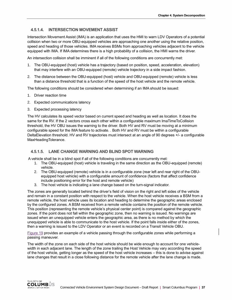
Chapter 4. System Decomposition
Connected Vehicle Environment System Design Document – Draft Report | Smart Columbus Program | 37
4.5.1.4. INTERSECTION MOVEMENT ASSIST
Intersection Movement Assist (IMA) is an application that uses the HMI to warn LDV Operators of a potential
collision when two or more OBU-equipped vehicles are approaching one another using the relative position,
speed and heading of those vehicles. IMA receives BSMs from approaching vehicles adjacent to the vehicle
equipped with IMA. If IMA determines there is a high probability of a collision, the HMI warns the driver.
An intersection collision shall be imminent if all of the following conditions are concurrently met:
1. The OBU-equipped (host) vehicle has a trajectory (based on position, speed, acceleration, elevation)
that may interfere with an OBU-equipped (remote) vehicle trajectory in a side impact fashion.
2. The distance between the OBU-equipped (host) vehicle and OBU-equipped (remote) vehicle is less
than a distance threshold that is a function of the speed of the host vehicle and the remote vehicle.
The following conditions should be considered when determining if an IMA should be issued:
1. Driver reaction time
2. Expected communications latency
3. Expected processing latency
The HV calculates its speed vector based on current speed and heading as well as location. It does the
same for the RV. If the 2 vectors cross each other within a configurable maximum ImaTimeToCollision
threshold, the HV OBU issues the warning to the driver. Both HV and RV must be moving at a minimum
configurable speed for the IMA feature to activate. . Both HV and RV must be within a configurable
DeltaElevation threshold. HV and RV trajectories must intersect at an angle of 90 degrees +/- a configurable
MaxHeadingTolerance.
4.5.1.5. LANE CHANGE WARNING AND BLIND SPOT WARNING
A vehicle shall be in a blind spot if all of the following conditions are concurrently met: 1. The OBU-equipped (host) vehicle is traveling in the same direction as the OBU-equipped (remote)
vehicle. 2. The OBU-equipped (remote) vehicle is in a configurable zone (rear left and rear right of the OBU-
equipped host vehicle) with a configurable amount of confidence (factors that affect confidence include positioning error for the host and remote vehicle)
3. The host vehicle is indicating a lane change based on the turn-signal indicator.
The zones are generally located behind the driver’s field of vision on the right and left sides of the vehicle and remain in a constant position with respect to the vehicle. When the host vehicle receives a BSM from a remote vehicle, the host vehicle uses its location and heading to determine the geographic areas enclosed by the configured zones. A BSM received from a remote vehicle contains the position of the remote vehicle. This position (representing the remote vehicle’s physical center point) is compared against the geographic zones. If the point does not fall within the geographic zone, then no warning is issued. No warnings are issued when an unequipped vehicle enters the geographic area, as there is no method by which the unequipped vehicle is able to communicate to the host vehicle. If the point falls inside either of the zones, then a warning is issued to the LDV Operator or an event is recorded on a Transit Vehicle OBU.
Figure 19 provides an example of a vehicle passing through the configurable zones while performing a passing maneuver.
The width of the zone on each side of the host vehicle should be wide enough to account for one vehicle-width in each adjacent lane. The length of the zone trailing the Host Vehicle may vary according the speed of the host vehicle, getting longer as the speed of the host vehicle increases – this is done to advise against lane changes that result in a close following distance for the remote vehicle after the lane change is made.

Chapter 4. System Decomposition
38 | Smart Columbus Program | Connected Vehicle Environment System Design Document – Draft Report
Host
BSM
Remote
1 2 3
LCW/BSWWarning
Zone(YH, XH)
(YR, XR) (YR, XR) (YR, XR)
(figure is not to scale)
Source: City of Columbus
Figure 19: Lane Change Warning/Blind Spot Warning Example
4.5.2. Red Light Violation Warning
The Red-Light Violation Warning (RLVW) application enables a connected vehicle approaching a signalized
intersection to receive information about the signal timing and geometry of the intersection. The application
in the vehicle uses its speed and acceleration profile, along with the signal timing and geometry information,
to determine if it appears that the vehicle will enter the intersection in violation of a traffic signal. If the
violation seems likely to occur, a warning can be provided to the vehicle operator. This application provides
an output to drivers to improve awareness when approaching a signal that will turn red before arriving at the
intersection to address crashes between multiple vehicles at intersections.
The RSU broadcasts SPaT, MAP, and RTCM which is received by the OBU. The OBU determines the
position of the vehicle within the MAP. This requires the vehicle to receive its current position via GNSS and
correcting it using the data contained in the RTCM. Next the OBU determines if it is within any of the ingress
approaches to the intersection. If it is determined that the vehicle is not located along any of the ingress
approaches, then no warning is issued. However, if the OBU determines that the vehicle is on one of the
ingress lane approaches, then the signal state for that approach must next be determined. The ingress
approach lane geometry indicated in the MAP message is associated with one or more connections (to
egress lanes). Each connection has an associated SignalGroupID, which allows data from the SPaT
message to be joined back to each connection and approach.

Chapter 4. System Decomposition
Connected Vehicle Environment System Design Document – Draft Report | Smart Columbus Program | 39
3 5 7 3
Protected-only Phase Progression (left turn, right turn)
3 6 8 3
Protected-Permissive Phase Progression (left turn)
3 6 8 5 7 3
Right Turn Pseudo-lap
3 6 6 6 8 3
Source: City of Columbus
Figure 20: MovementPhaseState Values of Typical Signal State Progressions
A Red-Light Violation is imminent if any of the following conditions are met:

Chapter 4. System Decomposition
40 | Smart Columbus Program | Connected Vehicle Environment System Design Document – Draft Report
1. The host vehicle crosses the stop line on a red signal indication at any speed. Exception for
vehicles that come to a complete stop prior to crossing stop bar with flashing red or where right turn
on red is permitted. The relevant signal state is determined by looking at the movementPhaseState
data element (SPaT Message) for the approach lane the vehicle is traveling in. The geometry for all
approach lanes is contained in the MAP message. The host vehicle’s current position is compared
against each lane geometry in the MAP message to determine which approach the vehicle is on.
2. Given the host vehicle‘s current speed, the front of host vehicle will cross the stop bar after the phase changes to red. The amount of time until the phase changes to red is determined by assessing the minEndTime, maxEndTime, and likelyTime data elements in the SPaT message. The amount of time (in seconds) it takes the host vehicle to cross the stop bar (𝑡) at its current speed is calculated using a modified version of the Haversine Equation:
𝑡 =20902464(2 atan2(√1−𝑎,√𝑎))
1.47 𝑉𝐻, where
• 𝑎 = sin2 (𝑌𝑆𝐵−𝑌𝐻
2) + cos(𝑌𝐻)cos(𝑌𝑆𝐵)sin2 (
𝑋𝑆𝐵−𝑋𝐻
2)
• 𝑌𝑆𝐵 is the latitude of the position of the stop bar of the lane that the Host vehicle is traveling in (converted to radians)
• 𝑋𝑆𝐵 is the longitude of the position of the stop bar of the lane that the Host vehicle is traveling in (converted to radians)
• 𝑌𝐻 is the latitude of the host vehicle (converted to radians)
• 𝑋𝐻 is the longitude of the host vehicle (converted to radians)
• 𝑉𝐻 is the speed of the host vehicle (mph)
If the calculated time is greater than the amount of time until the phase change, then the condition is satisfied
3. During a red signal state, the host vehicle is traveling too quickly to be able to decelerate to a stop prior to crossing the stop bar at a normal deceleration rate. The relevant signal state is determined by looking at the movementPhaseState data element (SPaT Message) for the approach lane the vehicle is traveling in. The geometry for all approach lanes is contained in the MAP message. The host vehicle’s current position is compared against each lane geometry in the MAP message to determine which approach the vehicle is on. The distance (𝑑) between the center point of the OBU-equipped (host) vehicle and the stop bar vehicle is less than a critical distance threshold (𝑑𝐶) that represents the stopping distance.
The distance (in feet) between the vehicle center point and the stop bar (𝑑) is calculated using the Haversine Equation:
𝑑 = 20902464 (2 atan2(√1 − 𝑎, √𝑎)), where
• 𝑎 = sin2 (𝑌𝑆𝐵−𝑌𝐻
2) + cos(𝑌𝐻)cos(𝑌𝑆𝐵)sin2 (
𝑋𝑆𝐵−𝑋𝐻
2)
• 𝑌𝑆𝐵 is the latitude of the position of the stop bar of the lane that the Host vehicle is traveling in (converted to radians)
• 𝑋𝑆𝐵 is the longitude of the position of the stop bar of the lane that the Host vehicle is traveling in (converted to radians)
• 𝑌𝐻 is the latitude of the host vehicle (converted to radians)
• 𝑋𝐻 is the longitude of the host vehicle (converted to radians)
The critical distance threshold (𝑑𝐶) (in feet) represents the stopping distance and is calculated using the following equation which takes into account driver reaction time, the speed of the host vehicle, the length of the host vehicle, and expected communications/processing latency.
𝑑𝐶 = 1.47𝑉𝐻(𝑡𝑃𝑅 + 𝑡𝐿) +(𝑉𝐻)2
30 (𝑎
32.2∓ 𝐺)
+𝐿𝐻
2
• 𝑉𝐻 is the speed of the host vehicle (mph)
• 𝑡𝑃𝑅 is the perception/reaction time (s)
• 𝑡𝐿 is the expected communications/processing latency (s)
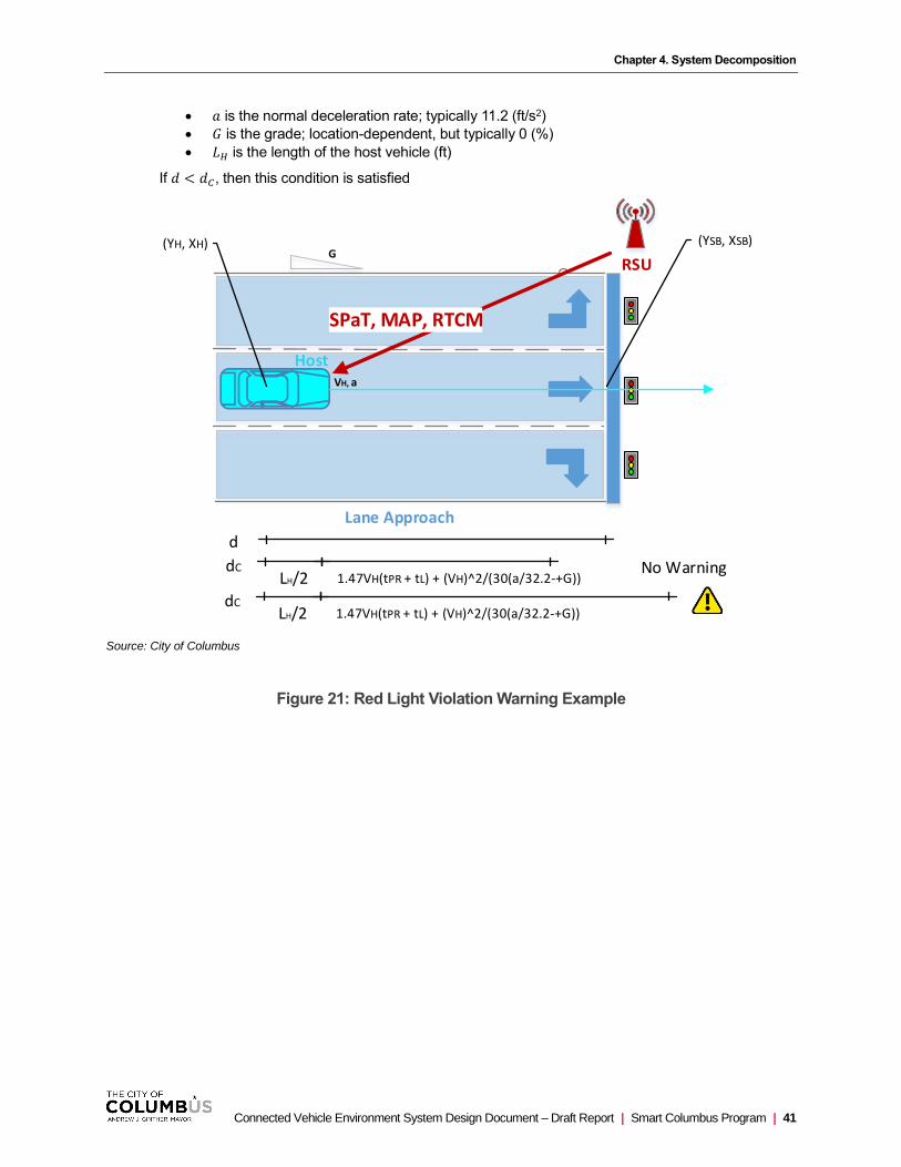
Chapter 4. System Decomposition
Connected Vehicle Environment System Design Document – Draft Report | Smart Columbus Program | 41
• 𝑎 is the normal deceleration rate; typically 11.2 (ft/s2)
• 𝐺 is the grade; location-dependent, but typically 0 (%)
• 𝐿𝐻 is the length of the host vehicle (ft)
If 𝑑 < 𝑑𝐶, then this condition is satisfied
Host
RSU
SPaT, MAP, RTCM
LH/2
d
dC1.47VH(tPR + tL) + (VH)^2/(30(a/32.2-+G))
Lane Approach
(YSB, XSB)(YH, XH)G
VH, a
LH/2dC
1.47VH(tPR + tL) + (VH)^2/(30(a/32.2-+G))
No Warning
Source: City of Columbus
Figure 21: Red Light Violation Warning Example
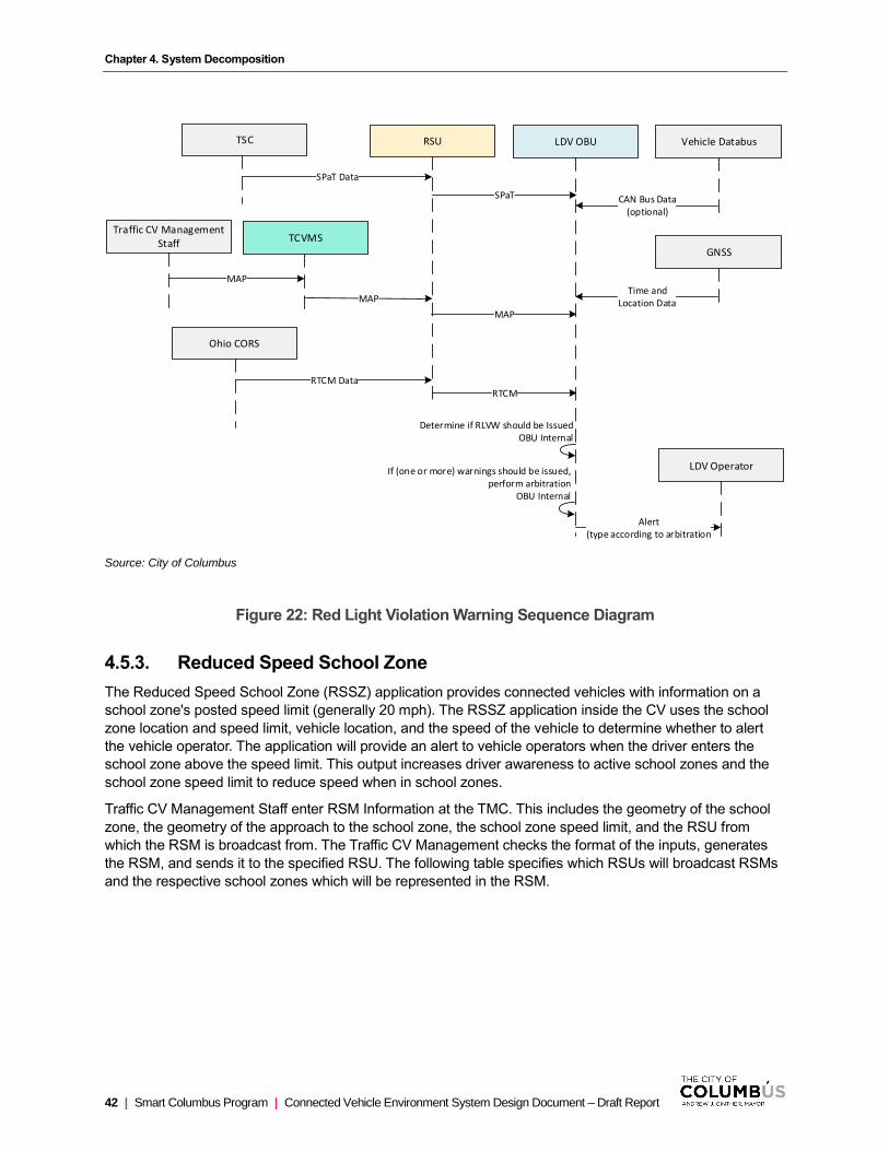
Chapter 4. System Decomposition
42 | Smart Columbus Program | Connected Vehicle Environment System Design Document – Draft Report
TCVMS
MAP
RSU LDV OBU
Determine if RLVW should be IssuedOBU Internal
SPaT
MAP
RTCM
Traffic CV Management Staff
MAP
TSC
SPaT Data
Ohio CORS
RTCM Data
GNSS
Time andLocation Data
Vehicle Databus
CAN Bus Data(optional)
LDV Operator
Alert(type according to arbitration
If (one or more) warnings should be issued,perform arbitration
OBU Internal
Source: City of Columbus
Figure 22: Red Light Violation Warning Sequence Diagram
4.5.3. Reduced Speed School Zone
The Reduced Speed School Zone (RSSZ) application provides connected vehicles with information on a
school zone's posted speed limit (generally 20 mph). The RSSZ application inside the CV uses the school
zone location and speed limit, vehicle location, and the speed of the vehicle to determine whether to alert
the vehicle operator. The application will provide an alert to vehicle operators when the driver enters the
school zone above the speed limit. This output increases driver awareness to active school zones and the
school zone speed limit to reduce speed when in school zones.
Traffic CV Management Staff enter RSM Information at the TMC. This includes the geometry of the school
zone, the geometry of the approach to the school zone, the school zone speed limit, and the RSU from
which the RSM is broadcast from. The Traffic CV Management checks the format of the inputs, generates
the RSM, and sends it to the specified RSU. The following table specifies which RSUs will broadcast RSMs
and the respective school zones which will be represented in the RSM.

Chapter 4. System Decomposition
Connected Vehicle Environment System Design Document – Draft Report | Smart Columbus Program | 43
Table 3: List of RSUs that Broadcast SRMs
School Name Intersection ID Intersection Name
Linden STEM Academy 3023 Aberdeen Ave. at Cleveland Ave.
3024 Cleveland Ave. at Weber Rd.
Clinton Elementary 4036 High St. at North Broadway
4037 High St. at Oakland Park Ave.
Our Lady of Peace School 4044 Dominion Blvd. at High St.
4045 High St. at Weisheimer Rd.
Source: City of Columbus
The RSU receives the RSM and stores it in local memory to prepare for broadcast. The next step is for the
RSU to receive an indication of whether or not the school zone signal is activated (flashing). All school zone
signals are locally activated (i.e. not activated through a central system), and thus roadside detection of the
school zone being active is also performed locally. This indication is provided by a detector measuring
voltage across or current to the school zone signal. If the detector indicates that the school zone is active,
then the RSU broadcasts the RSM. Likewise, if the detector indicates that the school zone is not active, the
RSU does not broadcast the RSM.
A vehicle approaching the active school zone receives the RSM. It uses information from GNSS, the vehicle
data bus and the RTCM message (received from the RSU) to position itself in the environment, and to
determine if a school zone warning should be issued to the vehicle operator. A Reduced Speed School Zone
Warning should be issued if any of the following conditions are met:
1. The host vehicle is in the school zone traveling above the school zone speed limit. The geometry of the school zone is contained in the RSM. The host vehicle’s current position is compared against the school zone geometry to determine if is in in the school zone. If so, the vehicle’s speed is compared against the school zone speed limit. If the speed of the host vehicle is greater than the school zone speed, then this condition is satisfied.
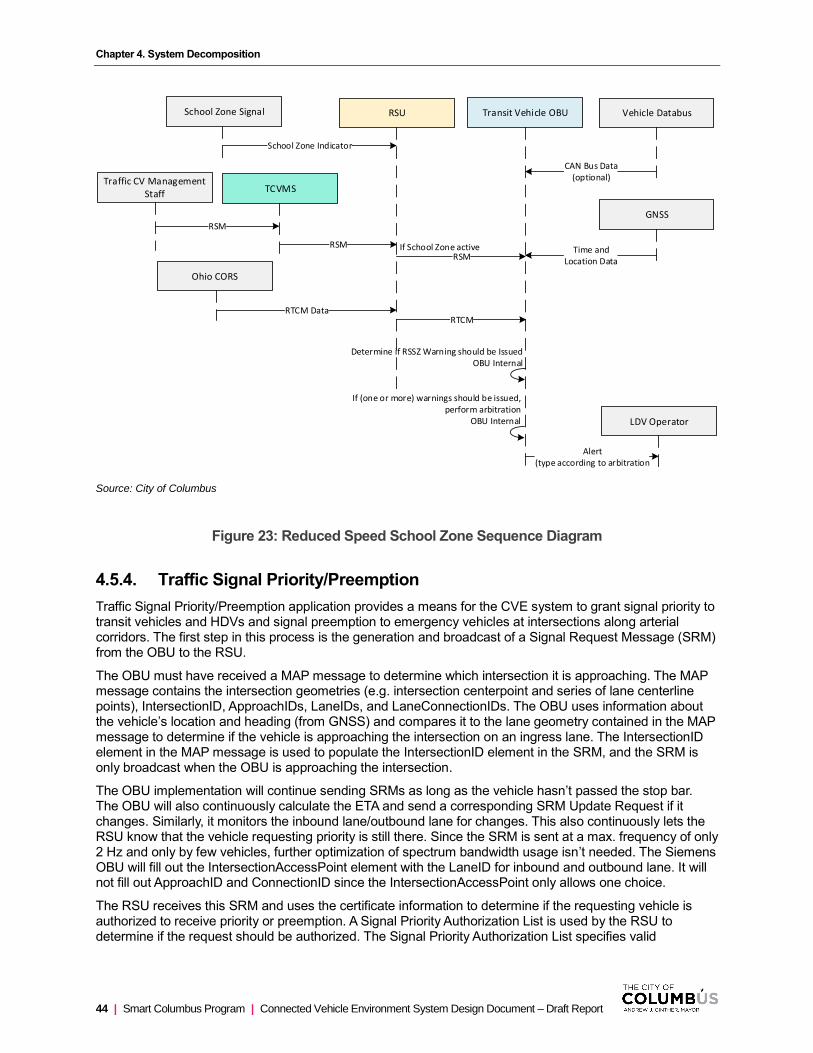
Chapter 4. System Decomposition
44 | Smart Columbus Program | Connected Vehicle Environment System Design Document – Draft Report
TCVMS
RSM
RSU Transit Vehicle OBU
Determine if RSSZ Warning should be IssuedOBU Internal
RSM
RTCM
Traffic CV Management Staff
RSM
School Zone Signal
School Zone Indicator
Ohio CORS
RTCM Data
If (one or more) warnings should be issued,perform arbitration
OBU Internal
If School Zone active
GNSS
Time andLocation Data
Vehicle Databus
CAN Bus Data(optional)
LDV Operator
Alert(type according to arbitration
Source: City of Columbus
Figure 23: Reduced Speed School Zone Sequence Diagram
4.5.4. Traffic Signal Priority/Preemption
Traffic Signal Priority/Preemption application provides a means for the CVE system to grant signal priority to transit vehicles and HDVs and signal preemption to emergency vehicles at intersections along arterial corridors. The first step in this process is the generation and broadcast of a Signal Request Message (SRM) from the OBU to the RSU.
The OBU must have received a MAP message to determine which intersection it is approaching. The MAP message contains the intersection geometries (e.g. intersection centerpoint and series of lane centerline points), IntersectionID, ApproachIDs, LaneIDs, and LaneConnectionIDs. The OBU uses information about the vehicle’s location and heading (from GNSS) and compares it to the lane geometry contained in the MAP message to determine if the vehicle is approaching the intersection on an ingress lane. The IntersectionID element in the MAP message is used to populate the IntersectionID element in the SRM, and the SRM is only broadcast when the OBU is approaching the intersection.
The OBU implementation will continue sending SRMs as long as the vehicle hasn’t passed the stop bar. The OBU will also continuously calculate the ETA and send a corresponding SRM Update Request if it changes. Similarly, it monitors the inbound lane/outbound lane for changes. This also continuously lets the RSU know that the vehicle requesting priority is still there. Since the SRM is sent at a max. frequency of only 2 Hz and only by few vehicles, further optimization of spectrum bandwidth usage isn’t needed. The Siemens OBU will fill out the IntersectionAccessPoint element with the LaneID for inbound and outbound lane. It will not fill out ApproachID and ConnectionID since the IntersectionAccessPoint only allows one choice.
The RSU receives this SRM and uses the certificate information to determine if the requesting vehicle is authorized to receive priority or preemption. A Signal Priority Authorization List is used by the RSU to determine if the request should be authorized. The Signal Priority Authorization List specifies valid

Chapter 4. System Decomposition
Connected Vehicle Environment System Design Document – Draft Report | Smart Columbus Program | 45
combinations of criteria that must be met to grant the request and is maintained by Traffic CV Management Staff. A number of factors to consider when building the Signal Priority Authorization List are provided in Appendix D.
When an RSU receives the SRM, the RSU compares data contained in the SRM against each combination of the criteria in the Priority Authorization List to determine if the priority or preemption request is granted and forwarded on to the traffic signal controller. These are outlined in the bulleted list below:
• Intersection ID in the SRM must match the Intersection ID of the MAP message being broadcast from the RSU. Note that MAP messages are broadcast from RSUs co-located with the signalized intersection defined in the MAP message.
• Intersection ID in the SRM must match an Intersection ID in the Priority Authorization List
• Connection ID in the SRM must match with the connection specified in the Priority Authorization List
• The local time on the RSU must be within the Valid Time and Valid Days criteria.
• The SRM must be accompanied by a valid electronic certificate
If all criteria are met, and the vehicle is authorized, the RSU communicates with the traffic signal controller to execute priority or preemption (specified in the SRM). The controller implements a signal phase timing change depending on whether priority or preemption was granted. Note that for an authorized priority request, the traffic signal controller will either provide an early green or extended green for the phase associated with the connection ID specified in the SRM. For an authorized preemption request, the traffic signal controller will interrupt the current phase (complete it in an expedient manner as possible) and proceed directly to the phase associated with the connection ID specified in the SRM. The traffic signal controller’s internal response to receiving a request to execute a priority or preemption strategy is defined in Appendix D.
The RSU sends the SSM to inform approaching vehicles about the status of each received request. When the OBU receives an SSM, it checks the list of requests being serviced to determine if the request that the OBU made has been included. If the SSM indicates that request is denied, the vehicle OBU ceases broadcasting the SRM. Similarly, if the SSM indicates that the request is granted and in the process of being serviced, then the vehicle ceases broadcasting the SRM. However, there may be a case where a request is being serviced, but the vehicle that made the request was not able to make it through the intersection after the request had been serviced.
While processing a particular request, additional requests may be received. In the case where multiple priority requests are granted, the requests will be serviced sequentially. The only exception for the sequential servicing of requests is when a new priority request can be serviced during the same phase as a previously-granted priority request. In this case, the requests are serviced simultaneously with the initial request. However, in the case where a priority request is being serviced, and a preemption request is granted, then signal operations will be immediately adjusted to first service the preemption request and then service the priority request. This change in order is reflected in the SSM. Finally, all preemption requests are serviced in the same order in which they are received, unless a new preemption request can be serviced during the same phase as a previously-granted preemption request. In this case, the requests are serviced simultaneously with the initial request.

Chapter 4. System Decomposition
46 | Smart Columbus Program | Connected Vehicle Environment System Design Document – Draft Report
Transit Vehicle OBU /Emergency Veh OBU /
HDV OBU
TCVMS RSU
RTCM
Traffic CV Management Staff
Ohio CORS
RTCM Data
TSC
SPaT Data
SPaT
Signal PriorityAuthorization List Signal Priority
Authorization List
Check Query AgainstAuthorization List
RSU Internal
SSM Data
SRM DataIf authorized
Determine if approaching intersectionDetermine if have received SSMOBU Internal
SSM
SRM
If approaching intersection,If have not received SSM
Emergency Vehicle Operator
Notification(Emergency Vehicle only)
If Signal Priority Granted
Determine if signal priority grantedOBU Internal
Source: City of Columbus
Figure 24: Traffic Signal Priority Sequence Diagram
4.5.5. Vehicle Data for Traffic Operations (VDTO)
VDTO essentially involves capturing all DSRC messages sent from or received by RSUs and sending them to the Traffic CV Management System (TCVMS) where they are archived.
• BSMs are produced by all CV-equipped vehicles. As all CV-equipped vehicles travel within DSRC range of an RSU, the BSM is captured by the RSU and is forwarded to the TCVMS. TCVMS staff configure the rate which captured BSMs on the roadside are forwarded to the TCVMS to conserve the amount of memory required to store CV data (by default, the RSU forwards all captured BSMs to the TCVMS). The TCVMS archives all BSMs received by RSUs. Since the same BSM may be received by multiple RSUs, the TCVMS will identify and eliminate any duplicate BSMs that it receives.
• SPaT message data are received by the RSU from the traffic signal controller. The RSU takes this data to form the SPaT message. To conserve the amount of memory required to store SPaT Messages, only messages where the MsgCount data element increments will be forwarded by the RSU to the TCVMS to be archived – this indicates a SPaT message where the message content has changed from the prior SPaT message sent.
• SRMs are produced by certain CV-equipped vehicles and received by RSUs. The SRM is expected to contain an intersection ID index. When the SRM received by an RSU contains the intersection ID
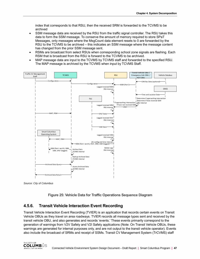
Chapter 4. System Decomposition
Connected Vehicle Environment System Design Document – Draft Report | Smart Columbus Program | 47
index that corresponds to that RSU, then the received SRM is forwarded to the TCVMS to be archived
• SSM message data are received by the RSU from the traffic signal controller. The RSU takes this data to form the SSM message. To conserve the amount of memory required to store SPaT Messages, only messages where the MsgCount data element resets to 0 are forwarded by the RSU to the TCVMS to be archived – this indicates an SSM message where the message content has changed from the prior SSM message sent.
• RSMs are broadcast from select RSUs when corresponding school zone signals are flashing. Each RSM that is broadcast from the RSU is forward to the TCVMS to be archived.
• MAP message data are input to the TCVMS by TCVMS staff and forwarded to the specified RSU. The MAP message is archived by the TCVMS when input by TCVMS Staff.
Traffic CV Management Staff
Archived Data Query
Archived Data Return
MAP, RSM
RSUTCVMS
BSM (Part I and II), SPaT, SRM, SSM (logged)
Logged received BSMRSU Internal
Delete LogsRSU Internal
Logged received SRMRSU Internal
(At configured time interval)
Logged received SPaTRSU Internal
Logged received SSMRSU Internal
Archive DataTCVMS Internal
Backup Archived DataTCVMS Internal
Access Archived DataTCVMS Internal
SPaT Data
SSM Data
TSC
Transit Vehicle OBU /Emergency Veh OBU /
HDV OBU
BSM (Part I)
SRM
Determine if approaching intersectionDetermine if have received SSMOBU InternalIf approaching intersection,
If have not received SSM
Smart Columbus Operating System
BSM (Part I and II), SRM,SSM, SPaT (logged)
MAP, RSM
GNSS
Time and Location Data
Vehicle Databus
CAN Bus Data (optional)Configuration
Configuration
Source: City of Columbus
Figure 25: Vehicle Data for Traffic Operations Sequence Diagram
4.5.6. Transit Vehicle Interaction Event Recording
Transit Vehicle Interaction Event Recording (TVIER) is an application that records certain events on Transit
Vehicle OBUs as they travel on area roadways. TVIER records all message types sent and received by the
transit vehicle OBU, and also generates and records ‘events.’ These events primarily correspond to the
generation of warnings from V2V Safety and V2I Safety applications (Note: On Transit Vehicle OBUs, these
warnings are generated for internal purposes only, and are not output to the transit vehicle operator). Events
also include the broadcast of SRMs and receipt of SSMs. Transit CV Management System (TrCVMS) staff

Chapter 4. System Decomposition
48 | Smart Columbus Program | Connected Vehicle Environment System Design Document – Draft Report
configure the period of time before and after each event which messages sent/received are saved and are
associated with the event.
All recorded messages and events are offloaded from the Transit Vehicle OBU when the Transit Vehicle
returns to the garage after each day of service. In the situation where a Transit Vehicle OBU attempts to
record more events than onboard memory allows, the oldest recorded events are overwritten by new events
until memory is freed up when event data is offloaded at the COTA garage.
• BSMs are produced by all CV-equipped vehicles. As all CV-equipped vehicles travel within DSRC range of a Transit Vehicle OBU, the BSM is captured by the Transit Vehicle OBU and captured as part of a Transit Vehicle Interaction Event.
• SPaT messages are received by the Transit Vehicle OBU from the RSU. To conserve the amount of memory required to store SPaT Messages, the OBU uses a configuration parameter which sets the probability of storing a SPaT. The parameter can be set to an integer value from 0 to 100 (representing probability of 0.00, 0.01, …, 1.00). With this approach if you wanted to store 10% of the SPaTs you would set the parameter to 10. This is a statistical method that is applied globally to all SPaTs received independent from the RSU which is sending the SPaT. The algorithm randomly deletes received SPaTs to achieve decimation factor.
• SRMs are produced by Transit Vehicle OBUs. They are recorded as they are broadcast.
• SSMs are received by the Transit Vehicle OBU from the RSU. They are recorded as they are received.
• RSMs are broadcast from select RSUs when corresponding school zone signals are flashing. Each RSM that is broadcast from the RSU is recorded by the Transit Vehicle OBU.
• MAP Messages are broadcast from RSUs. Each MAP that is broadcast from the RSU is logged and uploaded. Because these are sent less frequently than SPaTs they do not have as large of a memory footprint.
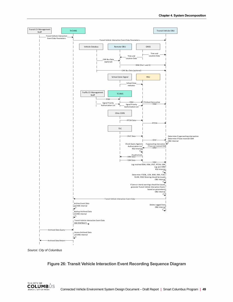
Chapter 4. System Decomposition
Connected Vehicle Environment System Design Document – Draft Report | Smart Columbus Program | 49
Transit Vehicle OBUTrCVMS
If (one or more) warnings should be issued, generate Transit Vehicle Interaction Event,
based on parameters)OBU Internal
Transit Vehicle Interaction Event Data
Determine if EEBL, LCW, BSW, IMA, FCW, RLVW, RSSZ Warning should be issued
OBU Internal
Transit Vehicle Interaction Event DataSee Interface 4
Archive Event DataTrCVMS Internal
Transit Vehicle Interaction Event Data Parameters
Backup Archived DataTCVMS Internal
Log received BSM, RSM, SPaT, RTCM, SSMLog sent SRMRSU Internal
Delete Logged DataOBU Internal
Access Archived DataTrCVMS Internal
Archived Data Query
Archived Data Return
Transit CV Management Staff
Transit Vehicle InteractionEvent Data Parameters
TCVMS
RSM
RSU
RSM
RTCM
Traffic CV Management Staff
RSM
School Zone Signal
School ZoneIndicator
Ohio CORS
RTCM Data
If School Zone active
TSC
SPaT Data
SPaT
Time andLocation Data
GNSS
Time andLocation Data
Vehicle Databus
CAN Bus Data (optional)
Remote OBU
BSM (Part I and II)
CAN Bus Data(optional)
Signal PriorityAuthorization List Signal Priority
Authorization List
Check Query AgainstAuthorization List
RSU Internal
SSM Data
SRM DataIf authorized
Determine if approaching intersectionDetermine if have received SSMOBU Internal
SSM
SRM
If approaching intersection,If have not received SSM
Source: City of Columbus
Figure 26: Transit Vehicle Interaction Event Recording Sequence Diagram
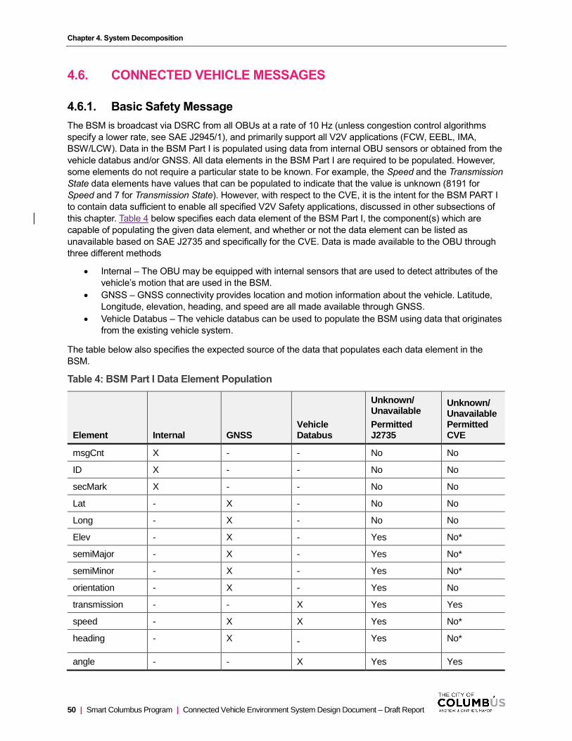
Chapter 4. System Decomposition
50 | Smart Columbus Program | Connected Vehicle Environment System Design Document – Draft Report
4.6. CONNECTED VEHICLE MESSAGES
4.6.1. Basic Safety Message
The BSM is broadcast via DSRC from all OBUs at a rate of 10 Hz (unless congestion control algorithms
specify a lower rate, see SAE J2945/1), and primarily support all V2V applications (FCW, EEBL, IMA,
BSW/LCW). Data in the BSM Part I is populated using data from internal OBU sensors or obtained from the
vehicle databus and/or GNSS. All data elements in the BSM Part I are required to be populated. However,
some elements do not require a particular state to be known. For example, the Speed and the Transmission
State data elements have values that can be populated to indicate that the value is unknown (8191 for
Speed and 7 for Transmission State). However, with respect to the CVE, it is the intent for the BSM PART I
to contain data sufficient to enable all specified V2V Safety applications, discussed in other subsections of
this chapter. Table 4 below specifies each data element of the BSM Part I, the component(s) which are
capable of populating the given data element, and whether or not the data element can be listed as
unavailable based on SAE J2735 and specifically for the CVE. Data is made available to the OBU through
three different methods
• Internal – The OBU may be equipped with internal sensors that are used to detect attributes of the
vehicle’s motion that are used in the BSM.
• GNSS – GNSS connectivity provides location and motion information about the vehicle. Latitude,
Longitude, elevation, heading, and speed are all made available through GNSS.
• Vehicle Databus – The vehicle databus can be used to populate the BSM using data that originates
from the existing vehicle system.
The table below also specifies the expected source of the data that populates each data element in the
BSM.
Table 4: BSM Part I Data Element Population
Element Internal GNSS Vehicle Databus
Unknown/ Unavailable
Permitted J2735
Unknown/ Unavailable Permitted CVE
msgCnt X - - No No
ID X - - No No
secMark X - - No No
Lat - X - No No
Long - X - No No
Elev - X - Yes No*
semiMajor - X - Yes No*
semiMinor - X - Yes No*
orientation - X - Yes No
transmission - - X Yes Yes
speed - X X Yes No*
heading - X - Yes No*
angle - - X Yes Yes
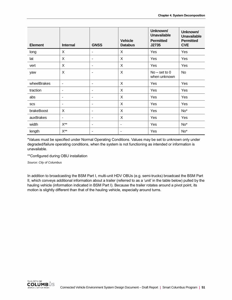
Chapter 4. System Decomposition
Connected Vehicle Environment System Design Document – Draft Report | Smart Columbus Program | 51
Element Internal GNSS Vehicle Databus
Unknown/ Unavailable
Permitted J2735
Unknown/ Unavailable Permitted CVE
long X - X Yes Yes
lat X - X Yes Yes
vert X - X Yes Yes
yaw X - X No – set to 0 when unknown
No
wheelBrakes - - X Yes Yes
traction - - X Yes Yes
abs - - X Yes Yes
scs - - X Yes Yes
brakeBoost X - X Yes No*
auxBrakes - - X Yes Yes
width X** - - Yes No*
length X** - - Yes No*
*Values must be specified under Normal Operating Conditions. Values may be set to unknown only under
degraded/failure operating conditions, when the system is not functioning as intended or information is
unavailable.
**Configured during OBU installation
Source: City of Columbus
In addition to broadcasting the BSM Part I, multi-unit HDV OBUs (e.g. semi-trucks) broadcast the BSM Part
II, which conveys additional information about a trailer (referred to as a ‘unit’ in the table below) pulled by the
hauling vehicle (information indicated in BSM Part I). Because the trailer rotates around a pivot point, its
motion is slightly different than that of the hauling vehicle, especially around turns.
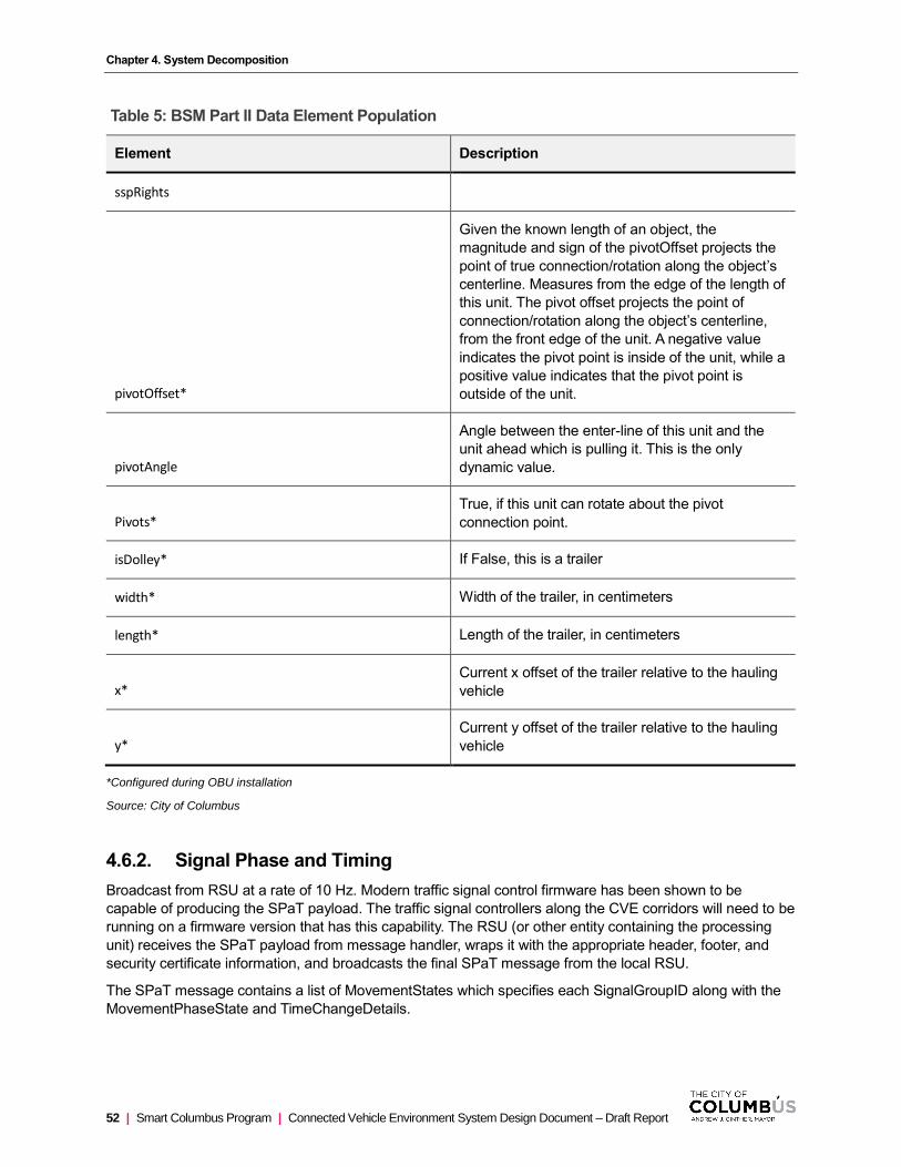
Chapter 4. System Decomposition
52 | Smart Columbus Program | Connected Vehicle Environment System Design Document – Draft Report
Table 5: BSM Part II Data Element Population
Element Description
sspRights
pivotOffset*
Given the known length of an object, the
magnitude and sign of the pivotOffset projects the
point of true connection/rotation along the object’s
centerline. Measures from the edge of the length of
this unit. The pivot offset projects the point of
connection/rotation along the object’s centerline,
from the front edge of the unit. A negative value
indicates the pivot point is inside of the unit, while a
positive value indicates that the pivot point is
outside of the unit.
pivotAngle
Angle between the enter-line of this unit and the
unit ahead which is pulling it. This is the only
dynamic value.
Pivots*
True, if this unit can rotate about the pivot
connection point.
isDolley* If False, this is a trailer
width* Width of the trailer, in centimeters
length* Length of the trailer, in centimeters
x* Current x offset of the trailer relative to the hauling
vehicle
y* Current y offset of the trailer relative to the hauling
vehicle
*Configured during OBU installation
Source: City of Columbus
4.6.2. Signal Phase and Timing
Broadcast from RSU at a rate of 10 Hz. Modern traffic signal control firmware has been shown to be
capable of producing the SPaT payload. The traffic signal controllers along the CVE corridors will need to be
running on a firmware version that has this capability. The RSU (or other entity containing the processing
unit) receives the SPaT payload from message handler, wraps it with the appropriate header, footer, and
security certificate information, and broadcasts the final SPaT message from the local RSU.
The SPaT message contains a list of MovementStates which specifies each SignalGroupID along with the
MovementPhaseState and TimeChangeDetails.

Chapter 4. System Decomposition
Connected Vehicle Environment System Design Document – Draft Report | Smart Columbus Program | 53
Table 6: MovementPhaseState Values
Value Description Note
1. Unavailable State is unknown or error -
2. Dark Signal head is dark Not In CVE
3. Stop then Proceed Flashing Red Not In CVE
4. Stop and Remain Solid Red Right-on-red permission indicated in MAP message
5. Pre Movement Pre-Green, Red + Yellow Not In CVE
6. Permissive Movement Allowed
Permissive Green -
7. Protected Movement Allowed
Protected Green U-Turns allowed are indicated in MAP message
8. Permissive Clearance Permissive Yellow -
9. Protected Clearance Protected Yellow -
10. Caution Conflicting Traffic Flashing Yellow Not In CVE
Source: City of Columbus
TimeChangeDetails contain the following data elements that provide information regarding when the current
phase will change to the next state. Thus, it is important to understand typical signal state progressions that
are used at intersection in the CVE. The following table indicates the typical signal state progressions used
in the CVE.
Figure 27: TimeChangeDetails Data Elements
Data Element CVE Required/Optional Description and Use
startTime Optional Time when the phase first started
minEndTime Required Expected shortest end time
maxEndTime Required Expected longest end time
likelyTime Required Best predicted value based on other data
Confidence Optional Confidence level of the likelyTime
nextTime Optional Rough estimate of when this phase will occur again
Source: City of Columbus
Chapter 4. System Decomposition
54 | Smart Columbus Program | Connected Vehicle Environment System Design Document – Draft Report
4.6.3. MapData Message
MAP messages are broadcast by RSUs, and for the CVE, they are primarily used by vehicle OBUs for the
RLVW and TSP applications.
Its primary use is to convey intersection lane geometry. The contents of this message involve defining the
details of indexing systems that are in turn used by other messages to relate additional information (for
example, the signal phase and timing via the SPaT message) to events at specific geographic locations on
the roadway.
MAP message payloads are generated and input to the CVE by the Traffic CV Management Staff. A process
for generating MAP messages has been devised – this process has been captured in detail in the MAP
Message Generation Process document (see Appendix E), but the main steps are provided in the bulleted
list below:
• Specify lane attributes for each lane object geometry in GIS. Lane geometry and attributes match the
data elements required by the SAE J2735 standard.
• Export data points and attributes from GIS (likely a database file or comma-separated values)
• Copy the GIS export into the proper cells in the spreadsheet-based tool. Note: ideally, the GIS output
can be generated in a format that is consistent with the format expected in the spreadsheet-based
tool.
• Input high-level intersection data required for the MAP message into the spreadsheet-based tool,
such as: Intersection ID, Intersection Name (readable), Intersection Centerpoint Coordinates, Master
Lane Width, and Message Revision Number
• Code in the spreadsheet-based tool is executed to produce the ISD intermediate file format.
• Load intermediate file into ISD
• Verify correct data entry in ISD and make any necessary adjustments
• Produce ASN.1 and UPER Hex encoded MAP message. Manage using Helix
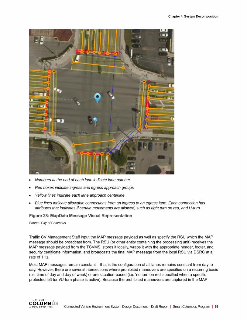
Chapter 4. System Decomposition
Connected Vehicle Environment System Design Document – Draft Report | Smart Columbus Program | 55
• Numbers at the end of each lane indicate lane number
• Red boxes indicate ingress and egress approach groups
• Yellow lines indicate each lane approach centerline
• Blue lines indicate allowable connections from an ingress to an egress lane. Each connection has
attributes that indicates if certain movements are allowed, such as right turn on red, and U-turn
Figure 28: MapData Message Visual Representation
Source: City of Columbus
Traffic CV Management Staff input the MAP message payload as well as specify the RSU which the MAP
message should be broadcast from. The RSU (or other entity containing the processing unit) receives the
MAP message payload from the TCVMS, stores it locally, wraps it with the appropriate header, footer, and
security certificate information, and broadcasts the final MAP message from the local RSU via DSRC at a
rate of 1Hz.
Most MAP messages remain constant – that is the configuration of all lanes remains constant from day to
day. However, there are several intersections where prohibited maneuvers are specified on a recurring basis
(i.e. time of day and day of week) or are situation-based (i.e. ‘no turn on red’ specified when a specific
protected left turn/U-turn phase is active). Because the prohibited maneuvers are captured in the MAP

Chapter 4. System Decomposition
56 | Smart Columbus Program | Connected Vehicle Environment System Design Document – Draft Report
message, the MAP message that is broadcast will have to be modified to account for changes in prohibited
maneuvers. A list of intersections where prohibited maneuvers are not constant are provided below:
• Morse Road and Malin St: Variable “No Turn on Red” sign for vehicles approaching from north and
south approach on Malin St.
• Morse Road and Northtowne Blvd/Walford St: Variable “No Turn on Red” sign for vehicles
approaching from north approach on Walford St and south approach on Northtowne Blvd.
• Morse Road and Heaton Rd.: Variable “No Turn on Red” sign for vehicles approaching from north
and south approach on Heaton Rd.
• Morse Road and Tamarak Blvd: Variable “No Turn on Red” sign for vehicles approaching from north
and south approach on Tamarak Blvd.
• Morse Road and Northland Ridge Blvd: Variable “No Turn on Red” sign for vehicles approaching
from north and south approach on Northland Ridge Blvd.
• Morse Road and McFadden Rd: Variable “No Turn on Red” sign for vehicles approaching from north
and south approach on McFadden Rd.
• Morse Road and Maize Rd: Variable “No Turn on Red” sign for vehicles approaching from north and
south approach on Maize Rd.
• Morse Road and Sandy Lane Rd: Variable “No Turn on Red” sign for vehicles approaching from
north and south approach on Sandy Lane Rd.
• Morse Road and Evanswood Dr: Variable “No Turn on Red” sign for vehicles approaching from north
approach on Evanswood Dr.
• Cleveland Ave at Second Ave: No Left Turns 4PM-6PM except buses for vehicles approaching from
south (NB) approach on Cleveland Ave.
• Cleveland Ave at Twenty-Fourth Ave: No Turn on Red MON-FRI 8AM-4PM for vehicles approaching
from south (NB) approach on Cleveland Ave. and vehicles approaching from east and west approach
on Twenty-Fourth Ave.
• Cleveland Ave. at Hudson Ave: No Turn on Red MON-FRI 8AM-4PM for vehicles approaching from
north (SB) approach on Cleveland Ave. and vehicles approaching from west (EB) approach on
Hudson Ave.
• Cleveland Ave. and Weber Rd.: No Turn on Red MON-FRI 8AM-4PM for vehicles approaching from
south (NB) approach on Cleveland Ave.
Logic in the signal controller may be used to determine which signal plan is in effect and thus which MAP
message shall be used at a given time.
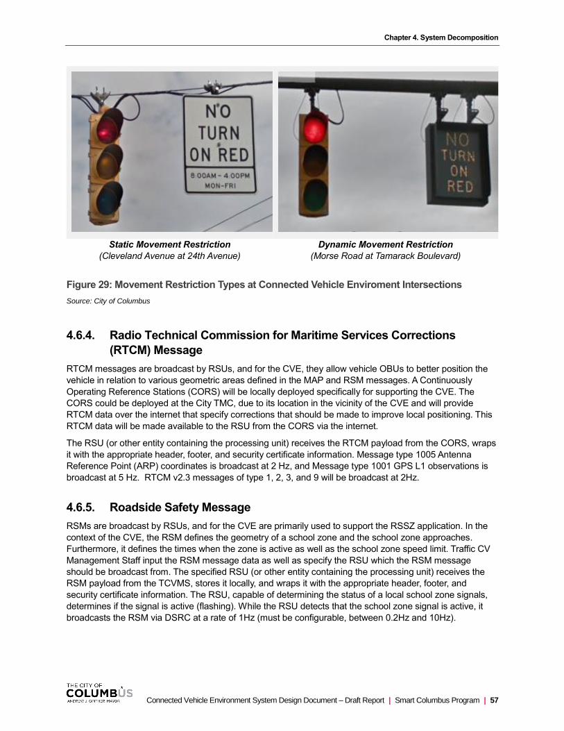
Chapter 4. System Decomposition
Connected Vehicle Environment System Design Document – Draft Report | Smart Columbus Program | 57
Static Movement Restriction
(Cleveland Avenue at 24th Avenue)
Dynamic Movement Restriction
(Morse Road at Tamarack Boulevard)
Figure 29: Movement Restriction Types at Connected Vehicle Enviroment Intersections
Source: City of Columbus
4.6.4. Radio Technical Commission for Maritime Services Corrections
(RTCM) Message
RTCM messages are broadcast by RSUs, and for the CVE, they allow vehicle OBUs to better position the
vehicle in relation to various geometric areas defined in the MAP and RSM messages. A Continuously
Operating Reference Stations (CORS) will be locally deployed specifically for supporting the CVE. The
CORS could be deployed at the City TMC, due to its location in the vicinity of the CVE and will provide
RTCM data over the internet that specify corrections that should be made to improve local positioning. This
RTCM data will be made available to the RSU from the CORS via the internet.
The RSU (or other entity containing the processing unit) receives the RTCM payload from the CORS, wraps
it with the appropriate header, footer, and security certificate information. Message type 1005 Antenna
Reference Point (ARP) coordinates is broadcast at 2 Hz, and Message type 1001 GPS L1 observations is
broadcast at 5 Hz. RTCM v2.3 messages of type 1, 2, 3, and 9 will be broadcast at 2Hz.
4.6.5. Roadside Safety Message
RSMs are broadcast by RSUs, and for the CVE are primarily used to support the RSSZ application. In the
context of the CVE, the RSM defines the geometry of a school zone and the school zone approaches.
Furthermore, it defines the times when the zone is active as well as the school zone speed limit. Traffic CV
Management Staff input the RSM message data as well as specify the RSU which the RSM message
should be broadcast from. The specified RSU (or other entity containing the processing unit) receives the
RSM payload from the TCVMS, stores it locally, and wraps it with the appropriate header, footer, and
security certificate information. The RSU, capable of determining the status of a local school zone signals,
determines if the signal is active (flashing). While the RSU detects that the school zone signal is active, it
broadcasts the RSM via DSRC at a rate of 1Hz (must be configurable, between 0.2Hz and 10Hz).
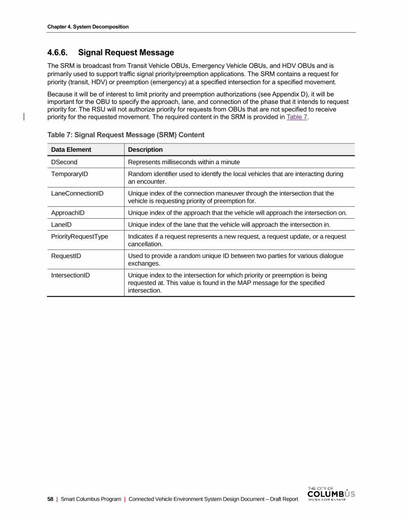
Chapter 4. System Decomposition
58 | Smart Columbus Program | Connected Vehicle Environment System Design Document – Draft Report
4.6.6. Signal Request Message
The SRM is broadcast from Transit Vehicle OBUs, Emergency Vehicle OBUs, and HDV OBUs and is
primarily used to support traffic signal priority/preemption applications. The SRM contains a request for
priority (transit, HDV) or preemption (emergency) at a specified intersection for a specified movement.
Because it will be of interest to limit priority and preemption authorizations (see Appendix D), it will be important for the OBU to specify the approach, lane, and connection of the phase that it intends to request priority for. The RSU will not authorize priority for requests from OBUs that are not specified to receive priority for the requested movement. The required content in the SRM is provided in Table 7.
Table 7: Signal Request Message (SRM) Content
Data Element Description
DSecond Represents milliseconds within a minute
TemporaryID Random identifier used to identify the local vehicles that are interacting during an encounter.
LaneConnectionID Unique index of the connection maneuver through the intersection that the vehicle is requesting priority of preemption for.
ApproachID Unique index of the approach that the vehicle will approach the intersection on.
LaneID Unique index of the lane that the vehicle will approach the intersection in.
PriorityRequestType Indicates if a request represents a new request, a request update, or a request cancellation.
RequestID Used to provide a random unique ID between two parties for various dialogue exchanges.
IntersectionID Unique index to the intersection for which priority or preemption is being requested at. This value is found in the MAP message for the specified intersection.

Chapter 4. System Decomposition
Connected Vehicle Environment System Design Document – Draft Report | Smart Columbus Program | 59
Data Element Description
Service Specific Permissions (SSP) Index
SSP contents in the Certificate (used to sign the message) specify the type of strategy (priority, preempt, other) requested in the SRM. SSPIndex values range from 0-31 (5 bits) and are locally defined. With respect to the SRM, the SSPIndex values are defined as follows:
0: Transit Vehicles. TSP enabled though CVE will be deployed alongside an existing TSP system. The existing system will continue to operate – the CV-based TSP will not affect signal operations even when a request is authorized.
1: Emergency Vehicles. This strategy allows the requesting vehicle to receive signal preemption. One of two strategies will be implemented: a. All phases transition to an all-red phase for a pre-determined amount of time. b. all phases transition to an all-red phase except for all ingress lanes on the emergency vehicle’s approach, which transition to green to allow traffic to ‘flush’ away from the queuing area before the emergency vehicle arrives to facilitate mobility.
2: HDVs. This strategy allows the requesting vehicle to receive signal priority. The purpose of signal priority for HDVs is reduction of emissions – the most benefit will be noticed when an HDV is prevented from decelerating (and subsequently accelerating) – and thus only green extensions are provided for the HDV approach.
Vehicles listed above will be provided certificates to sign the SRM with the specified SSP indices. This eliminates the likelihood of other users (not authorized to receive priority) from being able to successfully receive the type of certificate necessary to request priority or preemption. The roadside receiver uses the SSP index to determine the type of strategy to implement, if it determined the requesting entity is eligible.
Source: City of Columbus
Elements such as DSecond are populated based on the internal clock of the OBU, while the Temporary ID and Request ID are random integer values generated by the OBU.
The OBU uses information about the vehicle’s location and heading (from GNSS) and compares it to the lane geometry information from the MAP message to determine the ApproachID associated with the approach the vehicle is approaching the intersection from. This approach ID is used to populate the Approach ID field.
Similarly, the LaneID and LaneConnectionID are populated based on information about the vehicle’s location. However, it is ideal for the OBU to request only a particular movement through the intersection to minimize disruptions to traffic flow – requests will only be granted for certain movements for each vehicle according to the movements it is expected to make through the intersection. Signal priority and preemption strategies are explained in Appendix D. Both transit vehicles and HDVs have pre-established routes which ultimately limit the movements they will make through each intersection. Thus, as a transit vehicle or HDV approaches an intersection, it should know, based on its location and heading, which LaneID and LaneConnectionID should be specified in the SRM.
4.6.7. Signal Status Message
The SSM is broadcast from RSUs to support traffic signal priority/preemption applications. The SSM
provides an indication of all requests that have been made and the order in which they are being served and
is populated using data made available from the traffic signal controller. It is only broadcast via DSRC when
one or more requests are pending or when a request has been denied. The emergency vehicle OBU
(having recently made a request for preemption) uses the SSM to determine if preemption has been granted
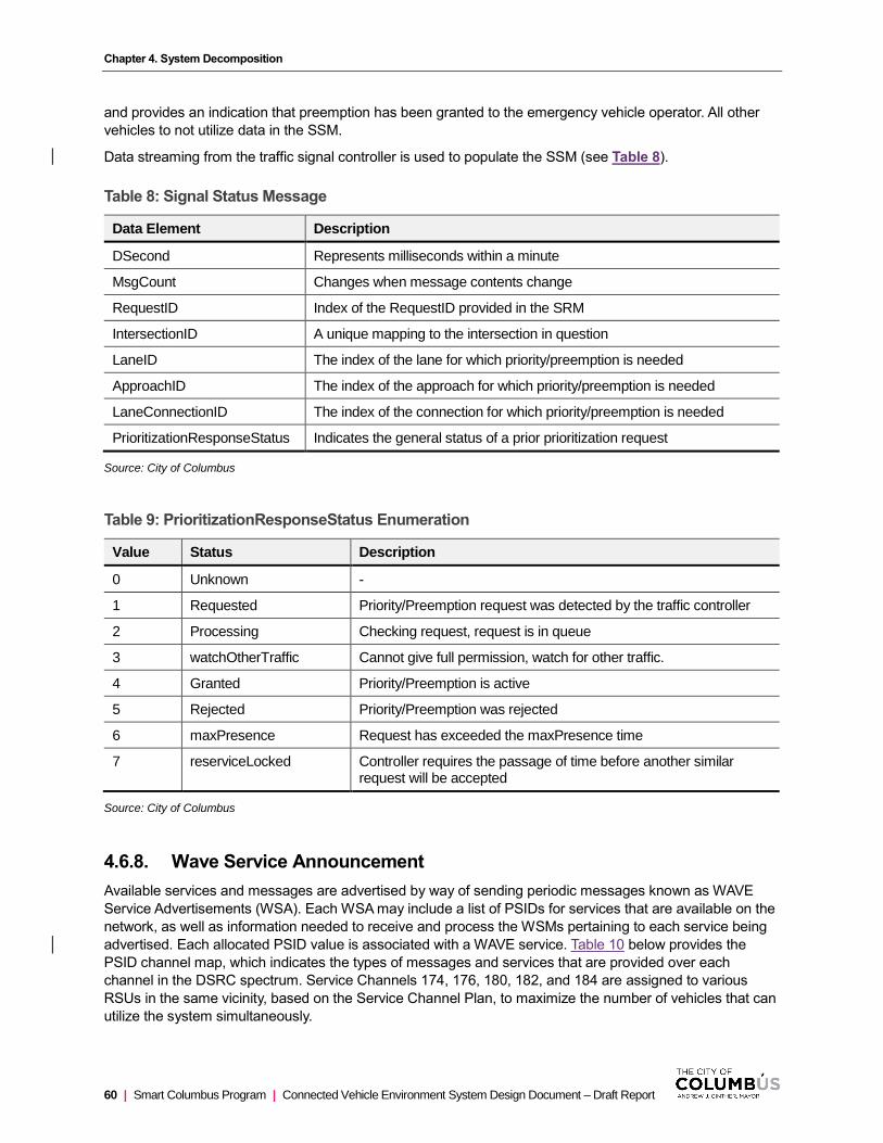
Chapter 4. System Decomposition
60 | Smart Columbus Program | Connected Vehicle Environment System Design Document – Draft Report
and provides an indication that preemption has been granted to the emergency vehicle operator. All other
vehicles to not utilize data in the SSM.
Data streaming from the traffic signal controller is used to populate the SSM (see Table 8).
Table 8: Signal Status Message
Data Element Description
DSecond Represents milliseconds within a minute
MsgCount Changes when message contents change
RequestID Index of the RequestID provided in the SRM
IntersectionID A unique mapping to the intersection in question
LaneID The index of the lane for which priority/preemption is needed
ApproachID The index of the approach for which priority/preemption is needed
LaneConnectionID The index of the connection for which priority/preemption is needed
PrioritizationResponseStatus Indicates the general status of a prior prioritization request
Source: City of Columbus
Table 9: PrioritizationResponseStatus Enumeration
Value Status Description
0 Unknown -
1 Requested Priority/Preemption request was detected by the traffic controller
2 Processing Checking request, request is in queue
3 watchOtherTraffic Cannot give full permission, watch for other traffic.
4 Granted Priority/Preemption is active
5 Rejected Priority/Preemption was rejected
6 maxPresence Request has exceeded the maxPresence time
7 reserviceLocked Controller requires the passage of time before another similar request will be accepted
Source: City of Columbus
4.6.8. Wave Service Announcement
Available services and messages are advertised by way of sending periodic messages known as WAVE
Service Advertisements (WSA). Each WSA may include a list of PSIDs for services that are available on the
network, as well as information needed to receive and process the WSMs pertaining to each service being
advertised. Each allocated PSID value is associated with a WAVE service. Table 10 below provides the
PSID channel map, which indicates the types of messages and services that are provided over each
channel in the DSRC spectrum. Service Channels 174, 176, 180, 182, and 184 are assigned to various
RSUs in the same vicinity, based on the Service Channel Plan, to maximize the number of vehicles that can
utilize the system simultaneously.
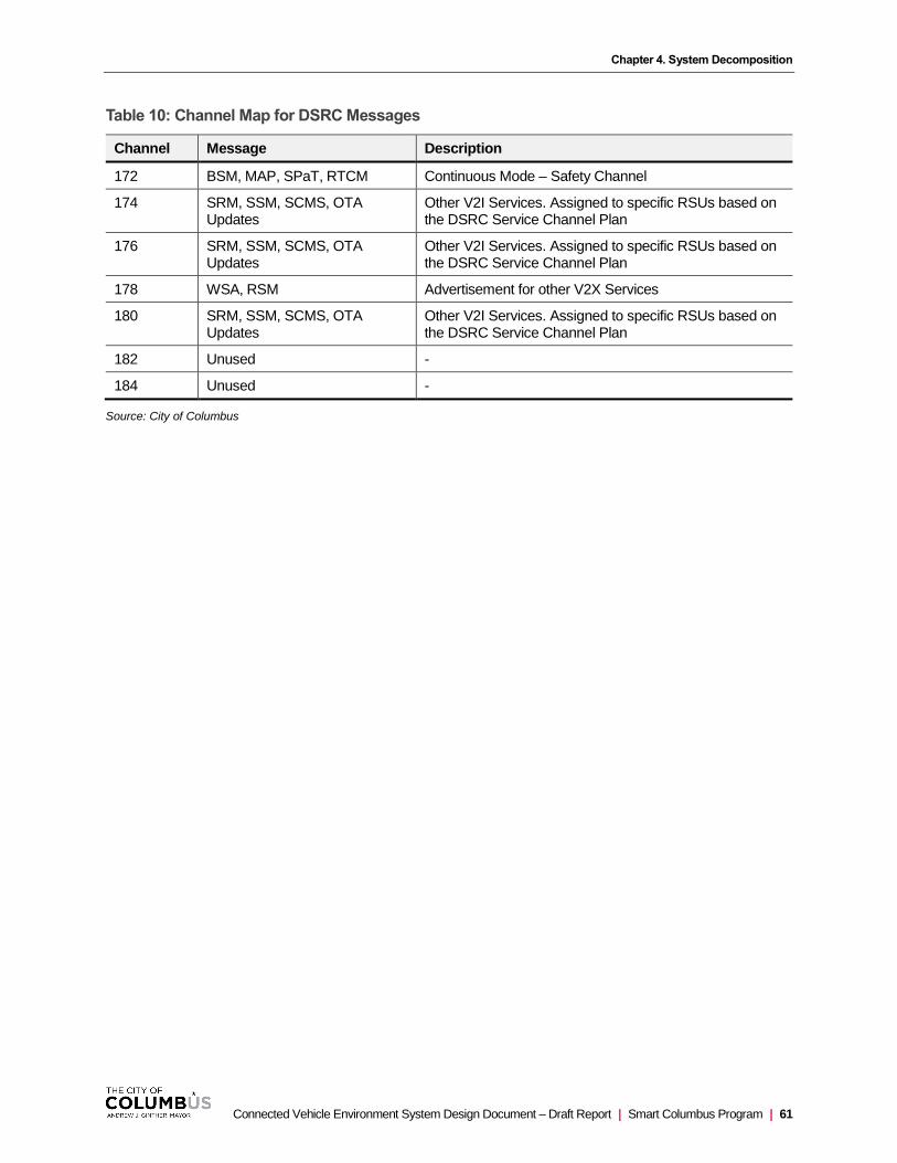
Chapter 4. System Decomposition
Connected Vehicle Environment System Design Document – Draft Report | Smart Columbus Program | 61
Table 10: Channel Map for DSRC Messages
Channel Message Description
172 BSM, MAP, SPaT, RTCM Continuous Mode – Safety Channel
174 SRM, SSM, SCMS, OTA Updates
Other V2I Services. Assigned to specific RSUs based on the DSRC Service Channel Plan
176 SRM, SSM, SCMS, OTA Updates
Other V2I Services. Assigned to specific RSUs based on the DSRC Service Channel Plan
178 WSA, RSM Advertisement for other V2X Services
180 SRM, SSM, SCMS, OTA Updates
Other V2I Services. Assigned to specific RSUs based on the DSRC Service Channel Plan
182 Unused -
184 Unused -
Source: City of Columbus

Connected Vehicle Environment System Design Document – Draft Report | Smart Columbus Program | 63
Design Rationale
The system design is predominately based on requirements and system interfaces that were developed
previously in the project. Content in previous project documents were developed with the primary scope of
the CVE in mind. That is, to realize the benefits of deploying CV technology into an operational environment,
and the deployment of applications that have demonstrated sufficient levels of development and testing. The
ability of the CVE to address the needs of users and subsequent requirements (captured in the Concept of
Operations and System Requirements Specification, respectively) depends on the availability of hardware
and software solutions that have been previously deployed (and subsequently improved upon). There is an
expectation to maximize the implementation of commercial off-the-shelf hardware and software to meet the
needs of users and stakeholders. As noted in the ConOps, driver-focused safety and mobility applications
which have met technology readiness level 6 were selected for inclusion. Applications that serve the needs
of local management agencies (Vehicle Data for Traffic Operations, Transit Vehicle Interaction Event
Recording), despite limited development, will be implemented as these applications primarily involve the
transfer of data – which is expected to require minimal amount of development to operate effectively in a
deployment environment. It has been previously decided that DSRC will be deployed as the wireless
interface to enable these applications.
The system design that is presented in this document is unique in that it is being performed during the
procurement process for the CVE. Thus, the rationale for the development of design will be based, in part,
on the ability of the selected offerors to meet the specifications that are developed. In March 2019, the City
of Columbus issued two requests for proposals (RFP) to implement the CVE. The CVE was divided into two
systems (RSU-based system and an OBU-based system). The RFPs indicated a need to procure two
systems integrators:
• The OBU vendor is responsible for the identification and procurement, development, configuration,
installation, testing, maintenance, and in the case of private vehicles, possible removal, of the in-
vehicle components that comprise the CVE
• The RSU vendor is responsible for the identification and procurement, provision, management,
operation and maintenance of the network of nearly 100 dedicated short-range communications
(DSRC)-based roadside units (RSUs) that comprise the CVE.
As part of the RFP response, each vendor was asked to indicate their ability to adhere to each system
requirement that was presented. These responses provided a lot of detail on which requirements could be
satisfied with the current state of technology. While vendors were able to meet a large number of
requirements with little or no modification to existing capabilities, all vendors indicated that there were some
requirements that could not be met (not without major modifications). The OBU and RSU integrators that
were ultimately selected have demonstrated that they are the most effective team at meeting requirements
and successfully developing and integrating their respective parts of the system. There may be instances in
the system design that may deviate from the system requirements that are based on responses that were
received from the selected vendors (changes to the system requirements document based on integrator
feedback will be reflected in the system requirements update).
The selected OBU and RSU system integrators are expected to work closely with the each other, their
respective equipment vendors (if different that the offeror), and the Management Team to ensure a
successful deployment of the CVE. An installation contractor hired by the City will also support installation of
the RSUs. All devices that are deployed are expected to be interoperable and should adhere to the
standards that have been identified. All deployed devices are expected to be OmniAir Certified at the time of
deployment. Hardware vendors and integrators may need to make modifications to ensure that standards
Chapter 5. Design Rationale
64 | Smart Columbus Program | Connected Vehicle Environment System Design Document – Draft Report
are being interpreted in the same manner so that interoperability can be achieved. Testing will be especially
important in instances where multiple vendors are involved so that progress (interoperability and adherence
to requirements and design) can be assessed and verified throughout the pre-deployment collaboration
process. To improve the likelihood of successful deployment, evidence of successful interoperability testing
will be expected to be provided (along with any relevant demonstrations) from vendors prior to deployment.
Finally, the Department of Technology (DoT) will play a significant role in the management and design of the
Columbus Traffic Signal System (CTSS), the fiber-optic network backhaul that will be leveraged to support
V2I applications and CVE system management activities. Thus, the DoT plays an important role in the
design of the network – the project team has coordinated with DoT to establish the CVE network design,
and to ensure that it meets the DoT’s network security protocols.

Connected Vehicle Environment System Design Document – Draft Report | Smart Columbus Program | 65
Acronyms and Definitions
Table 11: Acronym List
Abbreviation/Acronym Definition
APPS CV Applications
ATC Advanced Transportation Controller
BSM Basic Safety Message
BSW Blind Spot Warning Application
CCTN Columbus Connected Transportation Network
CEAV Connected Electric Automated Vehicle (Smart Columbus Project #8)
CFR Code of Federal Regulations
ConOps Concept of Operations
CORS Continuously Operating Reference Station
COTA Central Ohio Transit Authority
CTSS Columbus Traffic Signal System
CV Connected Vehicle
CVCP Connected Vehicle Co-Processor
CVE Connected Vehicle Environment (Smart Columbus Project #2)
CVRIA Connected Vehicle Reference Implementation Architecture
DOT (City of Columbus) Department of Technology
DPS Columbus Department of Public Service
DSRC Dedicated Short Range Communications
EEBL Emergency Electronic Brake Light Application
EOS Econolite Operating System
EVP Emergency Vehicle Preemption Application
FCW Forward Collision Warning Application
FSP Freight Signal Priority
GNSS Global Navigation Satellite System
HSM Hardware Security Module
ICD Interface Control Document
IEEE Institute of Electrical and Electronics Engineers
IMA Intersection Movement Assist Application
IP Internet Protocol Address
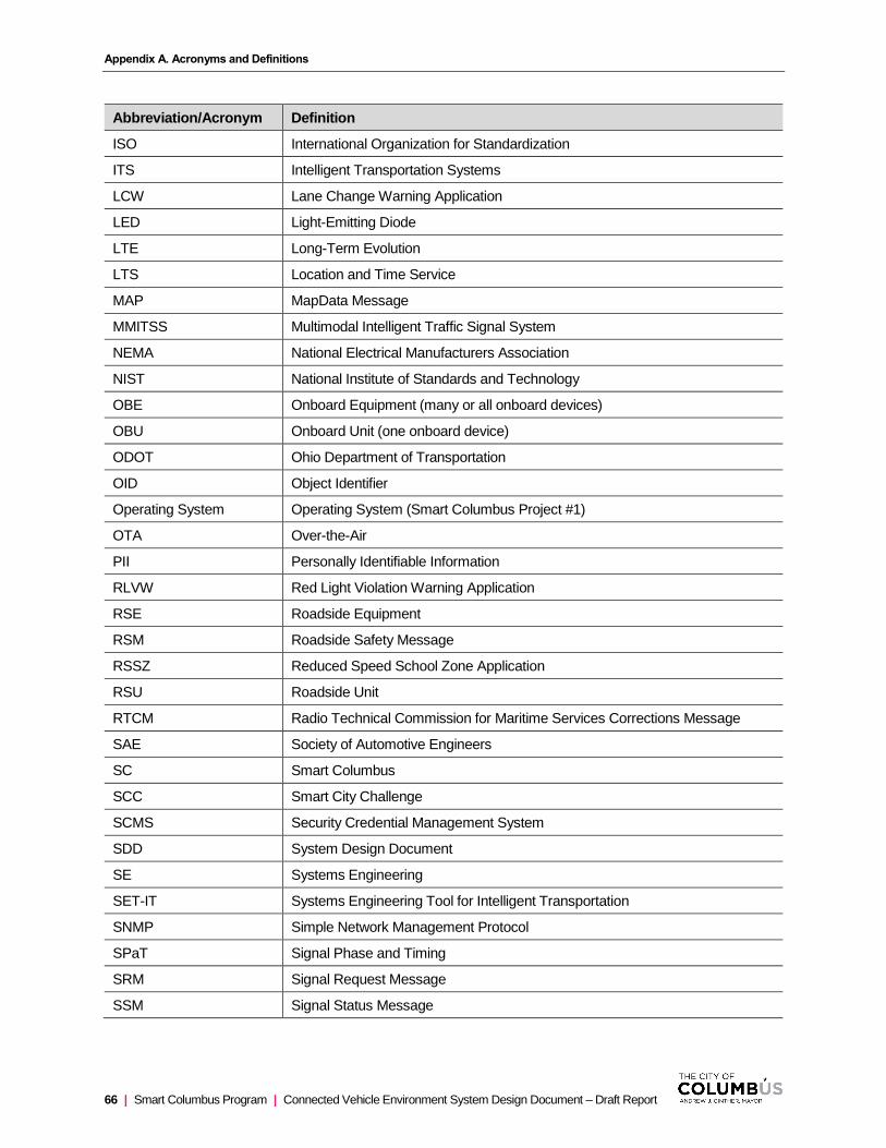
Appendix A. Acronyms and Definitions
66 | Smart Columbus Program | Connected Vehicle Environment System Design Document – Draft Report
Abbreviation/Acronym Definition
ISO International Organization for Standardization
ITS Intelligent Transportation Systems
LCW Lane Change Warning Application
LED Light-Emitting Diode
LTE Long-Term Evolution
LTS Location and Time Service
MAP MapData Message
MMITSS Multimodal Intelligent Traffic Signal System
NEMA National Electrical Manufacturers Association
NIST National Institute of Standards and Technology
OBE Onboard Equipment (many or all onboard devices)
OBU Onboard Unit (one onboard device)
ODOT Ohio Department of Transportation
OID Object Identifier
Operating System Operating System (Smart Columbus Project #1)
OTA Over-the-Air
PII Personally Identifiable Information
RLVW Red Light Violation Warning Application
RSE Roadside Equipment
RSM Roadside Safety Message
RSSZ Reduced Speed School Zone Application
RSU Roadside Unit
RTCM Radio Technical Commission for Maritime Services Corrections Message
SAE Society of Automotive Engineers
SC Smart Columbus
SCC Smart City Challenge
SCMS Security Credential Management System
SDD System Design Document
SE Systems Engineering
SET-IT Systems Engineering Tool for Intelligent Transportation
SNMP Simple Network Management Protocol
SPaT Signal Phase and Timing
SRM Signal Request Message
SSM Signal Status Message
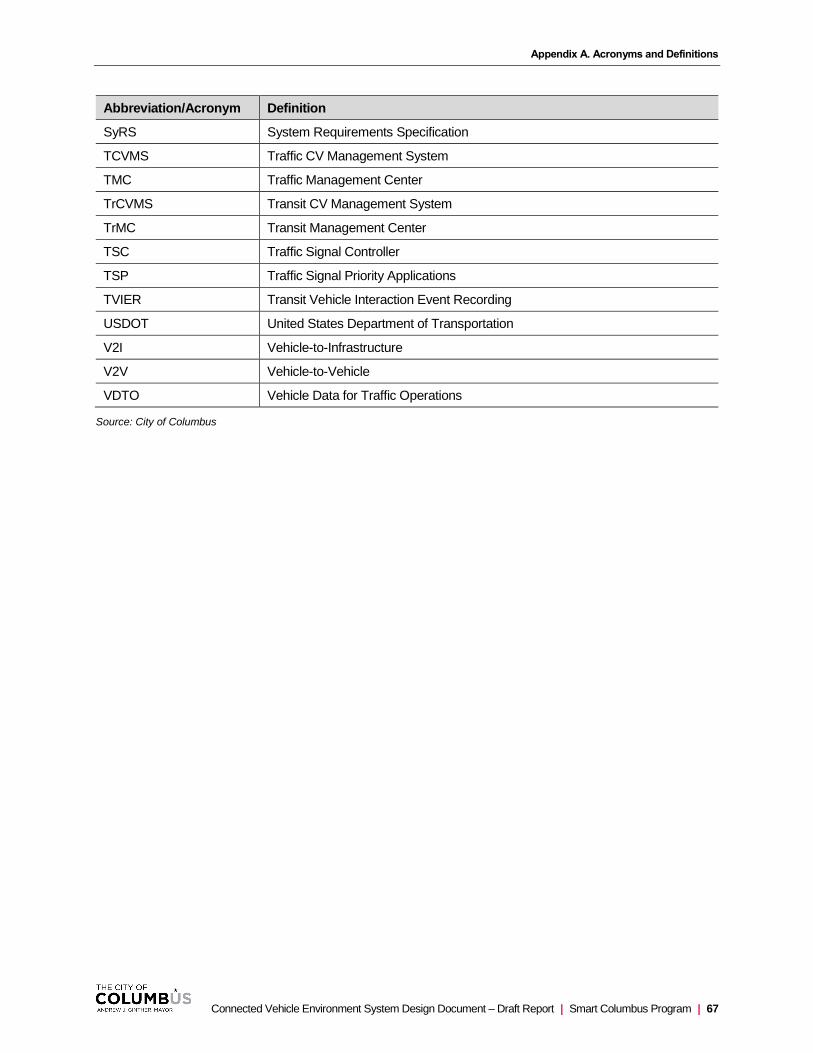
Appendix A. Acronyms and Definitions
Connected Vehicle Environment System Design Document – Draft Report | Smart Columbus Program | 67
Abbreviation/Acronym Definition
SyRS System Requirements Specification
TCVMS Traffic CV Management System
TMC Traffic Management Center
TrCVMS Transit CV Management System
TrMC Transit Management Center
TSC Traffic Signal Controller
TSP Traffic Signal Priority Applications
TVIER Transit Vehicle Interaction Event Recording
USDOT United States Department of Transportation
V2I Vehicle-to-Infrastructure
V2V Vehicle-to-Vehicle
VDTO Vehicle Data for Traffic Operations
Source: City of Columbus

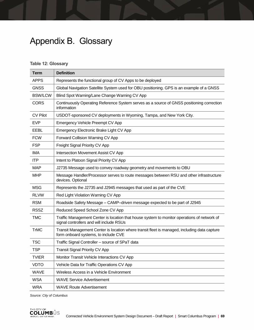
Connected Vehicle Environment System Design Document – Draft Report | Smart Columbus Program | 69
Glossary
Table 12: Glossary
Term Definition
APPS Represents the functional group of CV Apps to be deployed
GNSS Global Navigation Satellite System used for OBU positioning. GPS is an example of a GNSS
BSW/LCW Blind Spot Warning/Lane Change Warning CV App
CORS Continuously Operating Reference System serves as a source of GNSS positioning correction information
CV Pilot USDOT-sponsored CV deployments in Wyoming, Tampa, and New York City.
EVP Emergency Vehicle Preempt CV App
EEBL Emergency Electronic Brake Light CV App
FCW Forward Collision Warning CV App
FSP Freight Signal Priority CV App
IMA Intersection Movement Assist CV App
ITP Intent to Platoon Signal Priority CV App
MAP J2735 Message used to convey roadway geometry and movements to OBU
MHP Message Handler/Processor serves to route messages between RSU and other infrastructure devices. Optional
MSG Represents the J2735 and J2945 messages that used as part of the CVE
RLVW Red Light Violation Warning CV App
RSM Roadside Safety Message – CAMP–driven message expected to be part of J2945
RSSZ Reduced Speed School Zone CV App
TMC Traffic Management Center is location that house system to monitor operations of network of signal controllers and will include RSUs
TrMC Transit Management Center is location where transit fleet is managed, including data capture form onboard systems, to include CVE
TSC Traffic Signal Controller – source of SPaT data
TSP Transit Signal Priority CV App
TVIER Monitor Transit Vehicle Interactions CV App
VDTO Vehicle Data for Traffic Operations CV App
WAVE Wireless Access in a Vehicle Environment
WSA WAVE Service Advertisement
WRA WAVE Route Advertisement
Source: City of Columbus

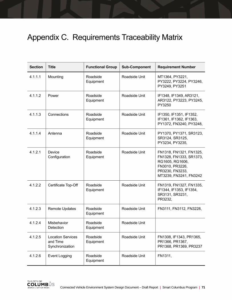
Connected Vehicle Environment System Design Document – Draft Report | Smart Columbus Program | 71
Requirements Traceability Matrix
Section Title Functional Group Sub-Component Requirement Number
4.1.1.1 Mounting Roadside
Equipment
Roadside Unit MT1364, PY3221,
PY3222, PY3224, PY3246,
PY3249, PY3251
4.1.1.2 Power Roadside
Equipment
Roadside Unit IF1348, IF1349, AR3121,
AR3122, PY3223, PY3245,
PY3250
4.1.1.3 Connections Roadside
Equipment
Roadside Unit IF1350, IF1351, IF1352,
IF1361, IF1362, IF1363,
PY1372, FN3240, PY3248,
4.1.1.4 Antenna Roadside
Equipment
Roadside Unit PY1370, PY1371, SR3123,
SR3124, SR3125,
PY3234, PY3235,
4.1.2.1 Device
Configuration
Roadside
Equipment
Roadside Unit FN1318, FN1321, FN1325,
FN1328, FN1333, SR1373,
RG1605, RG1606,
FN3010, PR3226,
PR3230, FN3233,
MT3239, FN3241, FN3242
4.1.2.2 Certificate Top-Off Roadside
Equipment
Roadside Unit FN1319, FN1327, FN1335,
IF1344, IF1353, IF1354,
SR3131, SR3231,
PR3232,
4.1.2.3 Remote Updates Roadside
Equipment
Roadside Unit FN3111, FN3112, FN3228,
4.1.2.4 Misbehavior
Detection
Roadside
Equipment
Roadside Unit
4.1.2.5 Location Services
and Time
Synchronization
Roadside
Equipment
Roadside Unit FN1308, IF1343, PR1365,
PR1366, PR1367,
PR1368, PR1369, PR3237
4.1.2.6 Event Logging Roadside
Equipment
Roadside Unit FN1311,

Appendix C. Requirements Traceability Matrix
72 | Smart Columbus Program | Connected Vehicle Environment System Design Document – Draft Report
Section Title Functional Group Sub-Component Requirement Number
4.1.2.7 Built-In Self-Test Roadside
Equipment
Roadside Unit PR3243, PR3244,
4.1.2.8 Message
Forwarding
Roadside
Equipment
Roadside Unit FN1310, FN1312, FN1317,
IF1341, IF1342, IF1345,
IF1356, IF1357, FN2972,
FN2973, FN2974, FN2975,
IF2978, FN2979, FN2980,
FN2981, FN2982, FN2983,
FN2987, FN2988, FN2989,
PR2994, FN3109,
PR3229, FN3238,
4.1.3 System Monitoring Roadside
Equipment
Roadside Unit FN1322, SR3127,
RE3128, PY3225,
4.1.4.1 Position Correction Roadside
Equipment
Roadside Unit FN1113, FN1313, IF1339,
IF1358, FN3236
4.1.4.2 Signal Request
Messages
Roadside
Equipment
Roadside Unit IF1347, IF1360, FN2990,
FN2991,
4.1.4.3 Signal Status
Messages
Roadside
Equipment
Roadside Unit FN1314, IF1340, IF1346,
IF1359, FN2976, FN2977,
IF2985, IF2986, IF2985,
IF2986, FN3000
4.1.5 Service Channel
Plan
Roadside
Equipment
Roadside Unit FN3227, IF3247,
4.2.1.1 Mounting Vehicle Onboard
Equipment
Light-Duty Vehicle
OBU
FN1203, MT1252,
MT1253, PR2907,
PR2913, PY3016, PY3018,
PY3202, PY3203, PY3206,
PY3207, PY3208, PY3209
4.2.1.2 Power Vehicle Onboard
Equipment
General OBU PY3201
4.2.1.3 Connections Vehicle Onboard
Equipment
General OBU SR1263, PY3216,
4.2.1.4 Human Machine
Interface
Vehicle Onboard
Equipment
Light-Duty Vehicle
OBU
PR3017, IF3019, PR3020,
FN3078, FN3196, PY3215,
PY3217, PY3219, PY3220
4.2.1.5 Antenna(ae) Vehicle Onboard
Equipment
General OBU FN1209, PY3205
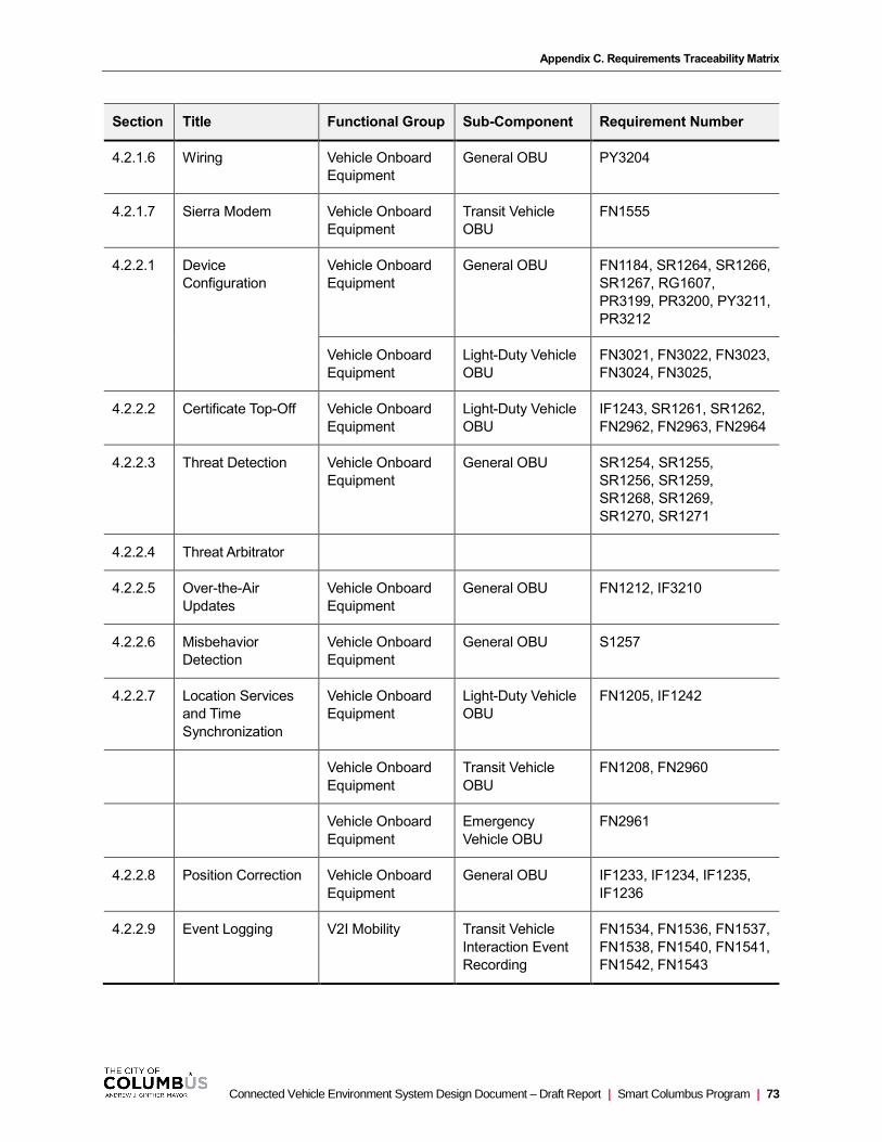
Appendix C. Requirements Traceability Matrix
Connected Vehicle Environment System Design Document – Draft Report | Smart Columbus Program | 73
Section Title Functional Group Sub-Component Requirement Number
4.2.1.6 Wiring Vehicle Onboard
Equipment
General OBU PY3204
4.2.1.7 Sierra Modem Vehicle Onboard
Equipment
Transit Vehicle
OBU
FN1555
4.2.2.1 Device
Configuration
Vehicle Onboard
Equipment
General OBU FN1184, SR1264, SR1266,
SR1267, RG1607,
PR3199, PR3200, PY3211,
PR3212
Vehicle Onboard
Equipment
Light-Duty Vehicle
OBU
FN3021, FN3022, FN3023,
FN3024, FN3025,
4.2.2.2 Certificate Top-Off Vehicle Onboard
Equipment
Light-Duty Vehicle
OBU
IF1243, SR1261, SR1262,
FN2962, FN2963, FN2964
4.2.2.3 Threat Detection Vehicle Onboard
Equipment
General OBU SR1254, SR1255,
SR1256, SR1259,
SR1268, SR1269,
SR1270, SR1271
4.2.2.4 Threat Arbitrator
4.2.2.5 Over-the-Air
Updates
Vehicle Onboard
Equipment
General OBU FN1212, IF3210
4.2.2.6 Misbehavior
Detection
Vehicle Onboard
Equipment
General OBU S1257
4.2.2.7 Location Services
and Time
Synchronization
Vehicle Onboard
Equipment
Light-Duty Vehicle
OBU
FN1205, IF1242
Vehicle Onboard
Equipment
Transit Vehicle
OBU
FN1208, FN2960
Vehicle Onboard
Equipment
Emergency
Vehicle OBU
FN2961
4.2.2.8 Position Correction Vehicle Onboard
Equipment
General OBU IF1233, IF1234, IF1235,
IF1236
4.2.2.9 Event Logging V2I Mobility Transit Vehicle
Interaction Event
Recording
FN1534, FN1536, FN1537,
FN1538, FN1540, FN1541,
FN1542, FN1543

Appendix C. Requirements Traceability Matrix
74 | Smart Columbus Program | Connected Vehicle Environment System Design Document – Draft Report
Section Title Functional Group Sub-Component Requirement Number
4.2.2.10 Log Offloading Vehicle Onboard
Equipment
Transit Vehicle
OBU
FN1206, IF3214
4.2.2.11 Built-In Self-Test Vehicle Onboard
Equipment
General OBU FN1185, FN1186,
4.2.2.12 Tamper Detection Vehicle Onboard
Equipment
General OBU SR1265
4.2.2.13 HMI Output Vehicle Onboard
Equipment
Light-Duty Vehicle
OBU
FN1107, FN1108, FN1115,
FN1116, FN1122, FN1123,
FN1124, FN1131, FN1132,
FN1138, FN1139, FN1187,
FN1188, FN1189, FN1190,
FN1191, FN1192, FN1193,
FN1194, FN1195, FN1196,
FN1197, FN1203, FN1210,
FN1213, IF1222, IF1246,
FN1286, FN1287, FN1299,
FN3011, FN3012, FN3013,
FN3014, FN3015, FN3026,
FN3196, FN3027, FN3080,
FN1298
Vehicle Onboard
Equipment
Emergency
Vehicle OBU
IF1247,
Vehicle Onboard
Equipment
General OBU FN1198
4.3.1 Physical/Mechanical Roadside
Equipment
Roadside Unit PY2912
4.3.2 Signal Operations
4.4.1 IP Allocation Roadside
Equipment
Roadside Unit PY3120, SR3126,
SR3129, SR3130
4.4.2 Circuit Type/Speed
4.5.1 Vehicle-to-Vehicle
Safety Applications
V2V Safety Blind Spot
Warning
PR1111. PR1112, FN3074,
PR3113
V2V Safety Emergency
Electronic Brake
Light Warning
PR119, PR1120, FN3075,
PR3114
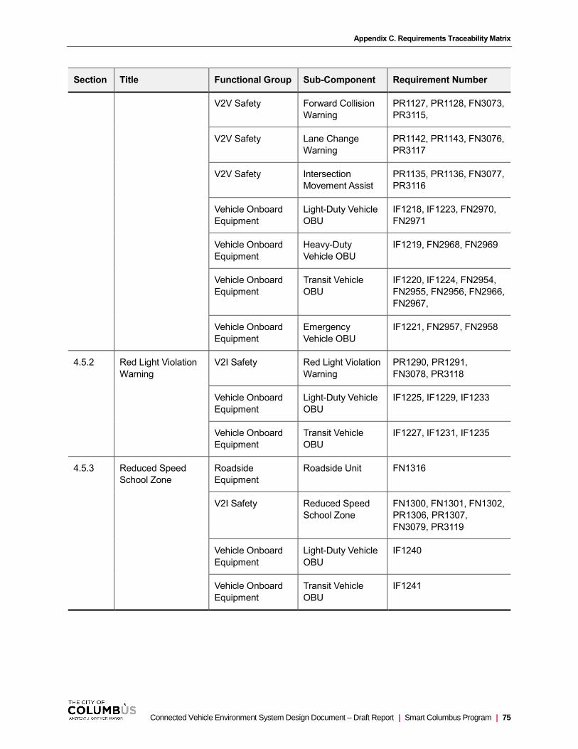
Appendix C. Requirements Traceability Matrix
Connected Vehicle Environment System Design Document – Draft Report | Smart Columbus Program | 75
Section Title Functional Group Sub-Component Requirement Number
V2V Safety Forward Collision
Warning
PR1127, PR1128, FN3073,
PR3115,
V2V Safety Lane Change
Warning
PR1142, PR1143, FN3076,
PR3117
V2V Safety Intersection
Movement Assist
PR1135, PR1136, FN3077,
PR3116
Vehicle Onboard
Equipment
Light-Duty Vehicle
OBU
IF1218, IF1223, FN2970,
FN2971
Vehicle Onboard
Equipment
Heavy-Duty
Vehicle OBU
IF1219, FN2968, FN2969
Vehicle Onboard
Equipment
Transit Vehicle
OBU
IF1220, IF1224, FN2954,
FN2955, FN2956, FN2966,
FN2967,
Vehicle Onboard
Equipment
Emergency
Vehicle OBU
IF1221, FN2957, FN2958
4.5.2 Red Light Violation
Warning
V2I Safety Red Light Violation
Warning
PR1290, PR1291,
FN3078, PR3118
Vehicle Onboard
Equipment
Light-Duty Vehicle
OBU
IF1225, IF1229, IF1233
Vehicle Onboard
Equipment
Transit Vehicle
OBU
IF1227, IF1231, IF1235
4.5.3 Reduced Speed
School Zone
Roadside
Equipment
Roadside Unit FN1316
V2I Safety Reduced Speed
School Zone
FN1300, FN1301, FN1302,
PR1306, PR1307,
FN3079, PR3119
Vehicle Onboard
Equipment
Light-Duty Vehicle
OBU
IF1240
Vehicle Onboard
Equipment
Transit Vehicle
OBU
IF1241
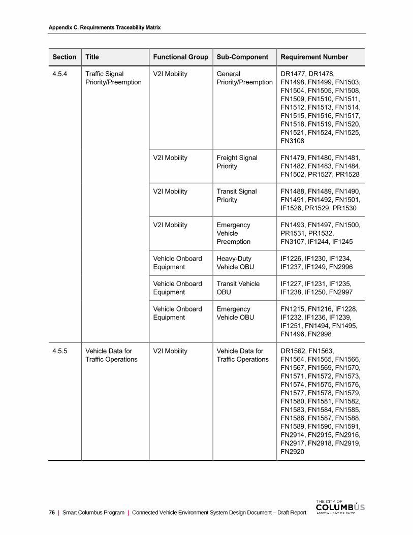
Appendix C. Requirements Traceability Matrix
76 | Smart Columbus Program | Connected Vehicle Environment System Design Document – Draft Report
Section Title Functional Group Sub-Component Requirement Number
4.5.4 Traffic Signal
Priority/Preemption
V2I Mobility General
Priority/Preemption
DR1477, DR1478,
FN1498, FN1499, FN1503,
FN1504, FN1505, FN1508,
FN1509, FN1510, FN1511,
FN1512, FN1513, FN1514,
FN1515, FN1516, FN1517,
FN1518, FN1519, FN1520,
FN1521, FN1524, FN1525,
FN3108
V2I Mobility Freight Signal
Priority
FN1479, FN1480, FN1481,
FN1482, FN1483, FN1484,
FN1502, PR1527, PR1528
V2I Mobility Transit Signal
Priority
FN1488, FN1489, FN1490,
FN1491, FN1492, FN1501,
IF1526, PR1529, PR1530
V2I Mobility Emergency
Vehicle
Preemption
FN1493, FN1497, FN1500,
PR1531, PR1532,
FN3107, IF1244, IF1245
Vehicle Onboard
Equipment
Heavy-Duty
Vehicle OBU
IF1226, IF1230, IF1234,
IF1237, IF1249, FN2996
Vehicle Onboard
Equipment
Transit Vehicle
OBU
IF1227, IF1231, IF1235,
IF1238, IF1250, FN2997
Vehicle Onboard
Equipment
Emergency
Vehicle OBU
FN1215, FN1216, IF1228,
IF1232, IF1236, IF1239,
IF1251, FN1494, FN1495,
FN1496, FN2998
4.5.5 Vehicle Data for
Traffic Operations
V2I Mobility Vehicle Data for
Traffic Operations
DR1562, FN1563,
FN1564, FN1565, FN1566,
FN1567, FN1569, FN1570,
FN1571, FN1572, FN1573,
FN1574, FN1575, FN1576,
FN1577, FN1578, FN1579,
FN1580, FN1581, FN1582,
FN1583, FN1584, FN1585,
FN1586, FN1587, FN1588,
FN1589, FN1590, FN1591,
FN2914, FN2915, FN2916,
FN2917, FN2918, FN2919,
FN2920

Appendix C. Requirements Traceability Matrix
Connected Vehicle Environment System Design Document – Draft Report | Smart Columbus Program | 77
Section Title Functional Group Sub-Component Requirement Number
4.5.6 Transit Vehicle
Interaction Event
Recording
V2I Mobility Transit Vehicle
Interaction Event
Recording
DR1533, FN1534,
FN1535, FN1536, FN1537,
FN1538, FN1539, FN1540,
FN1541, FN1542, FN1543,
FN1544, FN1545, FN1546,
FN1547, FN1548, FN1549,
FN1550, FN1551, FN1554,
FN1555, FN1556, FN1557,
FN1558, FN1559, FN1560,
IF1561, FN3081, FN3082,
FN3083, FN3084, FN3085,
FN3086, FN3087
4.6.1 Basic Safety
Message
DSRC Messages Basic Safety
Message
PR1105, PR3003,
DR3005, DR3006,
PR3007, PR3008, PR3009
4.6.2 Signal Phase and
Timing
DSRC Messages Signal Phase and
Timing
DR1378, DR1379,
DR1380, DR1381,
DR1382, DR1383,
DR1384, DR1385,
DR1386, DR1387,
DR1388, DR1389,
DR1390, DR1391,
DR1392, DR1393,
DR1394, DR1395,
DR1396, DR1397,
DR1398, DR1399,
DR1400, DR1401
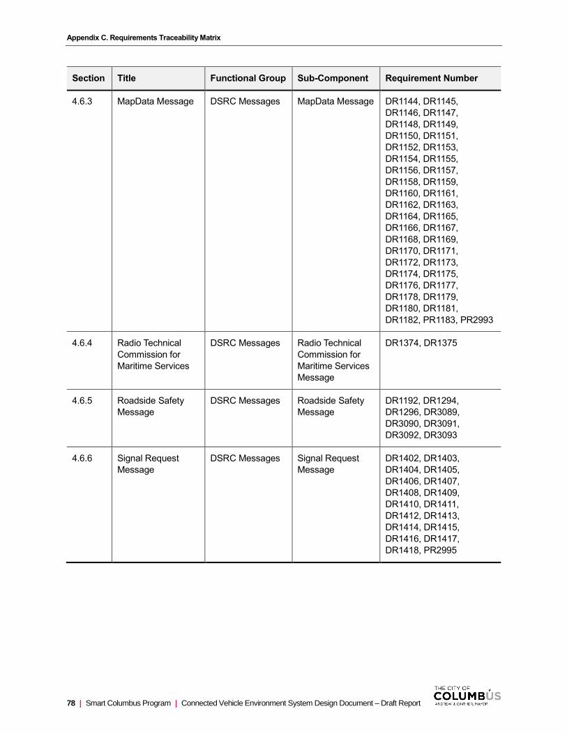
Appendix C. Requirements Traceability Matrix
78 | Smart Columbus Program | Connected Vehicle Environment System Design Document – Draft Report
Section Title Functional Group Sub-Component Requirement Number
4.6.3 MapData Message DSRC Messages MapData Message DR1144, DR1145,
DR1146, DR1147,
DR1148, DR1149,
DR1150, DR1151,
DR1152, DR1153,
DR1154, DR1155,
DR1156, DR1157,
DR1158, DR1159,
DR1160, DR1161,
DR1162, DR1163,
DR1164, DR1165,
DR1166, DR1167,
DR1168, DR1169,
DR1170, DR1171,
DR1172, DR1173,
DR1174, DR1175,
DR1176, DR1177,
DR1178, DR1179,
DR1180, DR1181,
DR1182, PR1183, PR2993
4.6.4 Radio Technical
Commission for
Maritime Services
DSRC Messages Radio Technical
Commission for
Maritime Services
Message
DR1374, DR1375
4.6.5 Roadside Safety
Message
DSRC Messages Roadside Safety
Message
DR1192, DR1294,
DR1296, DR3089,
DR3090, DR3091,
DR3092, DR3093
4.6.6 Signal Request
Message
DSRC Messages Signal Request
Message
DR1402, DR1403,
DR1404, DR1405,
DR1406, DR1407,
DR1408, DR1409,
DR1410, DR1411,
DR1412, DR1413,
DR1414, DR1415,
DR1416, DR1417,
DR1418, PR2995

Appendix C. Requirements Traceability Matrix
Connected Vehicle Environment System Design Document – Draft Report | Smart Columbus Program | 79
Section Title Functional Group Sub-Component Requirement Number
4.6.7 Signal Status
Message
DSRC Messages Signal Status
Message
DR1420, DR1421,
DR1422, DR1423,
DR1424, DR1425,
DR1426, DR1427,
DR1428, DR1429,
DR1430, DR1431,
DR1432, DR1433,
DR1434, DR1435,
DR1436, PR2999
4.6.8 Wave Service
Announcement
Vehicle Onboard
Equipment
General OBU FN3198

Connected Vehicle Environment System Design Document – Draft Report | Smart Columbus Program | 81
Signal Priority and Preemption Strategies
<<<At this time, the City has not specified a particular strategy to implement for executing signal priority or
preemption requests. The following text identifies types of strategies that are being considered.>>>
D.1 TYPE OF STRATEGIES
The following bulleted list provides strategies that may be used in the CVE. Note that this list is not final, nor
is it all inclusive.
• Early green priority allows time to be taken from a previous phase to provide an early green for the
phase of the approaching vehicle. The amount of time taken from the previous phase is a variable
that must be carefully considered to allow passage of the requesting vehicle, without adversely
impacting traffic being served during the phase that time is taken away from. This strategy is
expected to be made available to freight vehicles.
• Extended green priority allows time to be taken from the next phase to provide an extended green for
the phase of the approaching vehicle. The amount of time taken from the next phase is a variable that
must be carefully considered to allow passage of the requesting vehicle, without adversely impacting
traffic being served during the phase that time is taken away from. This strategy is expected to be
made available to freight vehicles.
• The all-red strategy changes all signals to a red state as soon as the existing movement has passed
its clearance phase. This would require all approaching traffic to come to a stop at the intersection.
Vehicles may continue to turn right on red, but as the emergency vehicle approaches the
intersections with lights and sirens on, these vehicles should pull over and stop to allow the
emergency vehicle to pass. This strategy is not ideal when traffic is heavy, especially on roads where
the movement of vehicles is constrained by barriers, as queued traffic will limit efficient movement of
the emergency vehicle.
• The flush strategy changes all movements of the approach of the emergency vehicle to a green state
as soon as the existing movement has passed its clearance phase. This would flush all vehicles
through the intersection, out of any path (left, through, right) that the emergency vehicle may take
through the intersection. The benefit of this strategy is that if implemented correctly, would be the
most efficient method, but if the emergency vehicle reaches the back of a queue before it has had a
chance to clear, then it could result in similar limitation of movement as the all-red strategy.
• The null strategy is only expected to be applicable for transit vehicles along the CMAX route (all other
transit vehicles will not be TSP enabled). When authorized, this strategy does not impact signal
operations in any way. Recall that the CVE is deployed alongside an existing TSP system. This null
strategy expected to allow the responsiveness of the existing system and a CV-based TSP system
(where a different strategy is enabled) to be compared.
D.2 EXPECTED MOVEMENTS
To better manage priority and preemption at CVE intersections, it will be advantageous to consider
movements that a vehicle is expected to make at a given intersection in determining whether or not it is

Appendix D. Signal Priority and Preemption Strategies
82 | Smart Columbus Program | Connected Vehicle Environment System Design Document – Draft Report
granted priority at that intersection. It is assumed that an emergency vehicle requesting preemption does not
have an expected movement, and preemption for all movements associated with the emergency vehicle
approach will be authorized. Buses and freight vehicles have established routes. Signal priority should only
be authorized for movements that those vehicles are expected to make through each intersection. CMAX
transit vehicles on Cleveland Avenue are only expected to make through movements along the Cleveland
Avenue corridor. Priority for transit vehicles will not be authorized for any other approaches or movements at
intersections in the CVE. Freight vehicles travel along the Alum Creek corridor and the Morse Road corridor
(east of I-270). Signal priority should only be authorized for freight vehicles for the following movements
• Alum Creek Drive at SR-317
Right Turn from SR-317 WB to Alum Creek Drive NB
Left Turn from Alum Creek Drive SB to SR-317 EB
• Alum Creek Drive at I-270 EB
Through movement for Alum Creek Drive SB
• Alum Creek Drive at I-270 WB
Left Turn from I-270 WB to Alum Creek Drive SB
• Morse Road at I-270 SB
Left Turn from Morse Road WB to I-270 SB
• Morse Road at I-270 NB
Right Turn from I-270 NB to Morse Road EB
Through movement for Morse Road WB
• Morse Road at Stygler Road
Right Turn from Morse Road EB to Stygler Road SB
Left Turn from Stygler Road NB to Morse Road WB
• All other intersections
Through movements for Morse Road/Alum Creek Drive
Priority for freight vehicles will not be authorized for any other approaches or movements at intersections in
the CVE.
D.3 TIME OF DAY
Different intersections will exhibit different types of demand throughout the course of a day. It may be
advantageous to limit priority or preemption to periods of the day were traffic flow will not be adversely
impacted. Alternatively, the type of strategy that is authorized for a particular vehicle may vary by time of
day. Time of day restrictions may vary from vehicle to vehicle, depending on local needs and preferences.
D.4 APPROACH
Certain strategies may be better suited for different types of approaches. It will be important to consider if
the type of priority that is granted varies if the vehicle is approaching from a major or minor approach. For
transit vehicles, it may be important to consider if there is a near or far-side stop for the movement where
priority is being requested. Due to the sometimes-unpredictable nature of bus dwelling times, it may be

Appendix D. Signal Priority and Preemption Strategies
Connected Vehicle Environment System Design Document – Draft Report | Smart Columbus Program | 83
advantageous to be selective in the strategies that are authorized at intersections with near or far side bus
stops.
D.5 TIME BETWEEN SUCCESSIVE REQUESTS
From time to time, it is expected that a requesting vehicle may not be able to pass through the intersection
despite having received authorization and the requested strategy being executed. In this case, the
requesting vehicle, determining that it has not cleared the intersection, may continue to request priority or
preemption, which may disrupt traffic on opposing approaches. To prevent multiple requests from having
excessive impacts on normal signal operations, a strategy may be put in place to limit authorizations for a
given vehicle (or group of vehicles) in a given time frame. A given amount of time must pass (cool down)
before a second priority request will be granted at the same intersection.

Connected Vehicle Environment System Design Document – Draft Report | Smart Columbus Program | 85
Map Message Generation Process
<<<Note: This process is continuously being refined, and while representative, may not reflect the final
procedure used to develop MAP Messages>>>
The Smart Columbus Connected Vehicle Environment is preparing to deploy hardware and software along
specified corridors in the Columbus region. There are several applications being supported that require the
transmission of MAP message, which must be generated in accordance with the system requirements and
relevant standards (SAE J2735). Through USDOT research, an online tool has been developed to facilitate
the development of MAP messages (ISD Message Creator1). The online tool allows a user to specify
various lane object geometries and related attributes that are required to populate the message.
To expedite the generation of MAP messages, a supplemental tool has been designed to allow collected
survey/CAD data to be entered along with other signal data. This tool leverages the offline saving feature
associated with the online tool – it processes data input by the user to generate the offline save file that
would have normally been generated by the online tool. This file can be imported into the online tool, which
would then be used to encode the message according to existing standards.
This spreadsheet-based tool allows for much more efficient entry of data, especially survey/CAD data that
has already been collected. Furthermore, as intersection geometries change, it allows multiple points to be
easily adjusted, if needed. The entry of data in the spreadsheet-based tool is more useful for entering data
for a large number of intersections and is expected to save time in the generation of MAP messages in
future deployments of CV Technology where accurate intersection geometry data is readily available.
One potential drawback: If the user makes changes in the ISD Message Generator, the offline save file
cannot be read into the spreadsheet-based tool; however, it is expected that additional code could be
developed to allow the save file, as generated by the online tool, to be converted into the spreadsheet-
based format. Also, data entry into spreadsheet can only be effectively reviewed by importing into the ISD
Message Generator and making manual checks. Any adjustments would have to be made in the
spreadsheet tool and again imported to ensure adjustments were correct. Finally, if the offline save file
format for the online tool changes, the code would have to be adjusted to conform to the updated output.
Depending on the scope of the update, this could result in significant modifications.
The most important part of generating the MAP message is the collection of geolocation information for
each lane object from surveys, CAD, and GIS. This includes but is not limited to ordered lane object
centerline latitude, longitude, elevation, and lane width data. Franklin County Engineer’s Office (FCEO)
maintains and is primarily responsible for information regarding intersection geometry.
In addition to lane geometry described above, attribute information will also be collected for each
intersection and for each lane object from existing as-built signal plans and intersection design. This data is
specified in detail in the next section. Note that methods for defining variables that are unique to the MAP
message (i.e. not traditionally found in signal timing plans) will need to be developed. Through collaboration
between FCEO and City of Columbus Department of Public Service (DPS), Intersection IDs and descriptive
intersection names have been defined (Appendix B: Intersection List), and a method for assigning Lane IDs
have been developed (Appendix C: Lane ID Assignment Method).
1 https://webapp.connectedvcs.com/isd/#

Appendix E. Map Message Generation Process
86 | Smart Columbus Program | Connected Vehicle Environment System Design Document – Draft Report
E.1 USING THE SUPPLEMENTAL TOOL
This section provides a guide for entering data into the supplemental data capture tool. The tool is based on
Microsoft Excel and consists of four tabs (Intersection Information, Lane Properties, Lane Points, and
Connection data) and a module that generates the save file (that is imported into the online tool).
Subsections are organized by each tab and use of the module. Because of their first-hand knowledge of
intersection geometry information, FCEO has been proposed to be primarily responsible for data entry into
the spreadsheet-based tool. There are instances where FECO may need to work with DPS to obtain
information that is input into the spreadsheet, which are specified in the text below. FCEO will have the full
support of DPS and consulting agencies (developer of the spreadsheet-based tool) working on the CVE
project throughout the MAP message development process.
Intersection Information
The Intersection Information tab contains a few basic information items regarding the intersection that is
being mapped.
• Latitude: The latitude (WGS 84) of the center of the intersection.
• Longitude: The longitude (WGS 84) of the center of the intersection.
• Elevation: The elevation (m) of the center point of the intersection.
• Name: A human-readable name for the given intersection. The name can be comprised of up to 64
characters and must be comprised of the first 128 characters of the ASCII alphabet. This includes all
upper/lowercase characters, including most special characters. For reference, the first 128 ASCII
characters are provided in Figure 34.
• Intersection ID: A locally defined value that is unique to a particular intersection in a given region
(Columbus metro). Allowable values are integers in a range from 0 to 65,535. Values 0-255 are
reserved for testing purposes. The City of Columbus DPS has defined intersection IDs to be used in
the CVE (see ).
• Master Lane Width: A reference value that other lane widths are compared against in specifying
lane geometries. This is explained further in the Lane Points tab. The Master Lane Width should be
the standard lane width used in the area. Allowable values are integers in a range of 0 to 32,767
centimeters.
• Revision Number: Used to keep track of message revisions. Should be changed to a new number
when a new MAP message is generated to replace a previously deployed MAP message. Allowable
values are integers in a range from 0-127.
After all data has been entered, the user executes the module which will output a file (located in the same
folder as the spreadsheet-based tool). This file can be imported into the online tool (File → Open Child
Map). A visual inspection of the lane lines is then performed to determine if any geometry data may have
been entered incorrectly. Note that lane centerline points may not appear exactly in the center of each lane
on the satellite view, as it is known that the satellite view is not necessarily accurately projected; however, it
will allow major discrepancies to be noticed. Inspection of the intersection center point and each approach
lane is then performed to determine if all other attributes were entered correctly. Any changes should be
made in the spreadsheet and reloaded into the tool.
After all data has been confirmed to have been entered correctly, the message can be encoded. This is
done by selecting Tools → Encoder, selecting all message options, and selecting “Encode”. The “UPER
Hex” field will contain the MAP message payload.
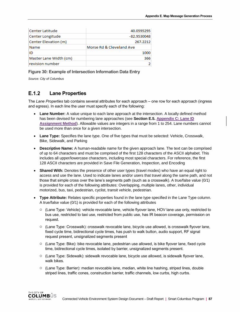
Appendix E. Map Message Generation Process
Connected Vehicle Environment System Design Document – Draft Report | Smart Columbus Program | 87
Figure 30: Example of Intersection Information Data Entry
Source: City of Columbus
Lane Properties
The Lane Properties tab contains several attributes for each approach – one row for each approach (ingress
and egress). In each line the user must specify each of the following:
• Lane Number: A value unique to each lane approach at the intersection. A locally defined method
has been devised for numbering lane approaches (see Section E.5. Appendix C: Lane ID
Assignment Method). Allowable values are integers in a range from 1 to 254. Lane numbers cannot
be used more than once for a given intersection.
• Lane Type: Specifies the lane type. One of five types that must be selected: Vehicle, Crosswalk,
Bike, Sidewalk, and Parking
• Descriptive Name: A human-readable name for the given approach lane. The text can be comprised
of up to 64 characters and must be comprised of the first 128 characters of the ASCII alphabet. This
includes all upper/lowercase characters, including most special characters. For reference, the first
128 ASCII characters are provided in Save File Generation, Inspection, and Encoding
• Shared With: Denotes the presence of other user types (travel modes) who have an equal right to
access and use the lane. Used to indicate lanes and/or users that travel along the same path, and not
those that simple cross over the lane’s segments path (such as a crosswalk). A true/false value (0/1)
is provided for each of the following attributes: Overlapping, multiple lanes, other, individual
motorized, bus, taxi, pedestrian, cyclist, transit vehicle, pedestrian.
• Type Attribute: Relates specific properties found in the lane type specified in the Lane Type column.
A true/false value (0/1) is provided for each of the following attributes
(Lane Type: Vehicle): vehicle revocable lane, vehicle flyover lane, HOV lane use only, restricted to
bus use, restricted to taxi use, restricted from public use, has IR beacon coverage, permission on
request.
(Lane Type: Crosswalk): crosswalk revocable lane, bicycle use allowed, is crosswalk flyover lane,
fixed cycle time, bidirectional cycle times, has push to walk button, audio support, RF signal
request present, unsignalized segments present
(Lane Type: Bike): bike revocable lane, pedestrian use allowed, is bike flyover lane, fixed cycle
time, bidirectional cycle times, isolated by barrier, unsignalized segments present.
(Lane Type: Sidewalk): sidewalk revocable lane, bicycle use allowed, is sidewalk flyover lane,
walk bikes.
(Lane Type: Barrier): median revocable lane, median, white line hashing, striped lines, double
striped lines, traffic cones, construction barrier, traffic channels, low curbs, high curbs.
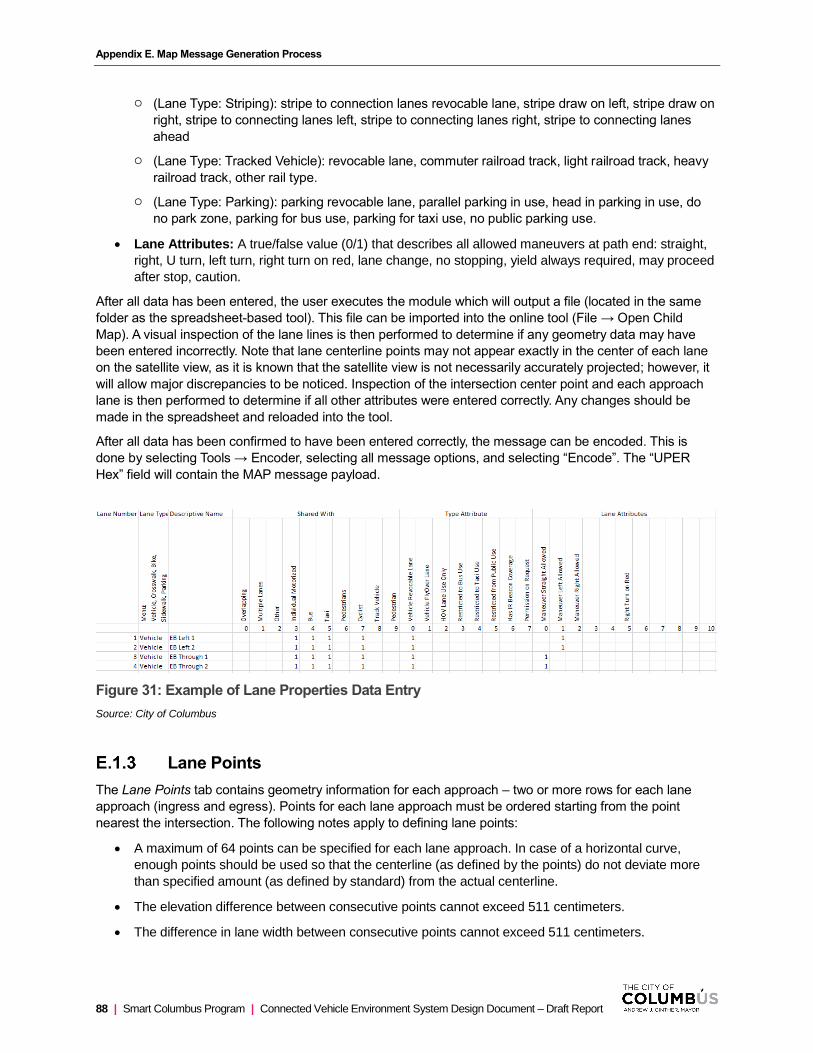
Appendix E. Map Message Generation Process
88 | Smart Columbus Program | Connected Vehicle Environment System Design Document – Draft Report
(Lane Type: Striping): stripe to connection lanes revocable lane, stripe draw on left, stripe draw on
right, stripe to connecting lanes left, stripe to connecting lanes right, stripe to connecting lanes
ahead
(Lane Type: Tracked Vehicle): revocable lane, commuter railroad track, light railroad track, heavy
railroad track, other rail type.
(Lane Type: Parking): parking revocable lane, parallel parking in use, head in parking in use, do
no park zone, parking for bus use, parking for taxi use, no public parking use.
• Lane Attributes: A true/false value (0/1) that describes all allowed maneuvers at path end: straight,
right, U turn, left turn, right turn on red, lane change, no stopping, yield always required, may proceed
after stop, caution.
After all data has been entered, the user executes the module which will output a file (located in the same
folder as the spreadsheet-based tool). This file can be imported into the online tool (File → Open Child
Map). A visual inspection of the lane lines is then performed to determine if any geometry data may have
been entered incorrectly. Note that lane centerline points may not appear exactly in the center of each lane
on the satellite view, as it is known that the satellite view is not necessarily accurately projected; however, it
will allow major discrepancies to be noticed. Inspection of the intersection center point and each approach
lane is then performed to determine if all other attributes were entered correctly. Any changes should be
made in the spreadsheet and reloaded into the tool.
After all data has been confirmed to have been entered correctly, the message can be encoded. This is
done by selecting Tools → Encoder, selecting all message options, and selecting “Encode”. The “UPER
Hex” field will contain the MAP message payload.
Figure 31: Example of Lane Properties Data Entry
Source: City of Columbus
Lane Points
The Lane Points tab contains geometry information for each approach – two or more rows for each lane
approach (ingress and egress). Points for each lane approach must be ordered starting from the point
nearest the intersection. The following notes apply to defining lane points:
• A maximum of 64 points can be specified for each lane approach. In case of a horizontal curve,
enough points should be used so that the centerline (as defined by the points) do not deviate more
than specified amount (as defined by standard) from the actual centerline.
• The elevation difference between consecutive points cannot exceed 511 centimeters.
• The difference in lane width between consecutive points cannot exceed 511 centimeters.
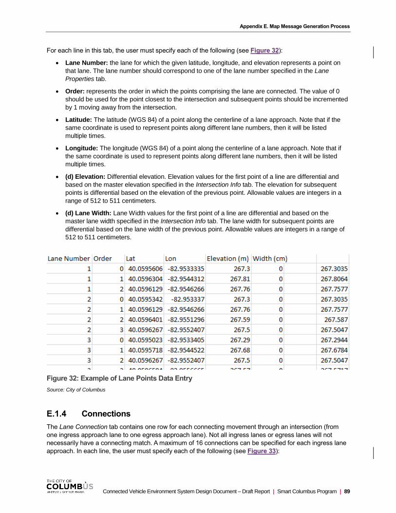
Appendix E. Map Message Generation Process
Connected Vehicle Environment System Design Document – Draft Report | Smart Columbus Program | 89
For each line in this tab, the user must specify each of the following (see Figure 32):
• Lane Number: the lane for which the given latitude, longitude, and elevation represents a point on
that lane. The lane number should correspond to one of the lane number specified in the Lane
Properties tab.
• Order: represents the order in which the points comprising the lane are connected. The value of 0
should be used for the point closest to the intersection and subsequent points should be incremented
by 1 moving away from the intersection.
• Latitude: The latitude (WGS 84) of a point along the centerline of a lane approach. Note that if the
same coordinate is used to represent points along different lane numbers, then it will be listed
multiple times.
• Longitude: The longitude (WGS 84) of a point along the centerline of a lane approach. Note that if
the same coordinate is used to represent points along different lane numbers, then it will be listed
multiple times.
• (d) Elevation: Differential elevation. Elevation values for the first point of a line are differential and
based on the master elevation specified in the Intersection Info tab. The elevation for subsequent
points is differential based on the elevation of the previous point. Allowable values are integers in a
range of 512 to 511 centimeters.
• (d) Lane Width: Lane Width values for the first point of a line are differential and based on the
master lane width specified in the Intersection Info tab. The lane width for subsequent points are
differential based on the lane width of the previous point. Allowable values are integers in a range of
512 to 511 centimeters.
Figure 32: Example of Lane Points Data Entry
Source: City of Columbus
Connections
The Lane Connection tab contains one row for each connecting movement through an intersection (from
one ingress approach lane to one egress approach lane). Not all ingress lanes or egress lanes will not
necessarily have a connecting match. A maximum of 16 connections can be specified for each ingress lane
approach. In each line, the user must specify each of the following (see Figure 33):
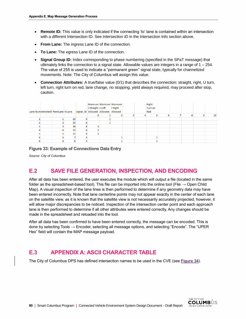
Appendix E. Map Message Generation Process
90 | Smart Columbus Program | Connected Vehicle Environment System Design Document – Draft Report
• Remote ID: This value is only indicated if the connecting ‘to’ lane is contained within an intersection
with a different Intersection ID. See Intersection ID in the Intersection Info section above.
• From Lane: The ingress Lane ID of the connection.
• To Lane: The egress Lane ID of the connection.
• Signal Group ID: Index corresponding to phase numbering (specified in the SPaT message) that
ultimately links the connection to a signal state. Allowable values are integers in a range of 1 – 254.
The value of 255 is used to indicate a “permanent green” signal state, typically for channelized
movements. Note: The City of Columbus will assign this value.
• Connection Attributes: A true/false value (0/1) that describes the connection: straight, right, U turn,
left turn, right turn on red, lane change, no stopping, yield always required, may proceed after stop,
caution.
Figure 33: Example of Connections Data Entry
Source: City of Columbus
E.2 SAVE FILE GENERATION, INSPECTION, AND ENCODING
After all data has been entered, the user executes the module which will output a file (located in the same
folder as the spreadsheet-based tool). This file can be imported into the online tool (File → Open Child
Map). A visual inspection of the lane lines is then performed to determine if any geometry data may have
been entered incorrectly. Note that lane centerline points may not appear exactly in the center of each lane
on the satellite view, as it is known that the satellite view is not necessarily accurately projected; however, it
will allow major discrepancies to be noticed. Inspection of the intersection center point and each approach
lane is then performed to determine if all other attributes were entered correctly. Any changes should be
made in the spreadsheet and reloaded into the tool.
After all data has been confirmed to have been entered correctly, the message can be encoded. This is
done by selecting Tools → Encoder, selecting all message options, and selecting “Encode”. The “UPER
Hex” field will contain the MAP message payload.
E.3 APPENDIX A: ASCII CHARACTER TABLE
The City of Columbus DPS has defined intersection names to be used in the CVE (see Figure 34).

Appendix E. Map Message Generation Process
Connected Vehicle Environment System Design Document – Draft Report | Smart Columbus Program | 91
Figure 34: Appendix A: ASCII Character Table
Source: https://simple.wikipedia.org/wiki/ASCII#/media/File:ASCII-Table-wide.svg
E.4 APPENDIX B: INTERSECTION LIST
Table 13 shows the Intersection IDs and Names DPS has defined.
Table 13: Appendix B: Intersection List
INT # INTERSECTION NAME CORRIDOR
3010 INT# 3010: CLEVELAND AVE. AT SECOND AVE. CLEVELAND AVE.
3012 INT# 3012: CLEVELAND AVE. AT FIFTH AVE. CLEVELAND AVE.
3013 INT# 3013: CLEVELAND AVE. AT ELEVENTH AVE. CLEVELAND AVE.
3014 INT# 3014: CLEVELAND AVE. AT WINDSOR AVE. CLEVELAND AVE.
3015 INT# 3015: CLEVELAND AVE. AT SEVENTEENTH AVE. CLEVELAND AVE.
3017 INT# 3017: CLEVELAND AVE. AT TWENTIETH AVE. CLEVELAND AVE.
3018 INT# 3018: CLEVELAND AVE. AT TWENTY-FOURTH AVE. CLEVELAND AVE.
3019 INT# 3019: CLEVELAND AVE. AT DUXBERRY AVE. CLEVELAND AVE.
3020 INT# 3020: CLEVELAND AVE. AT HUDSON AVE. CLEVELAND AVE.
3021 INT# 3021: CLEVELAND AVE. AT MRYTLE AVE. CLEVELAND AVE.
3022 INT# 3022: CLEVELAND AVE. AT GENESSEE AVE. CLEVELAND AVE.
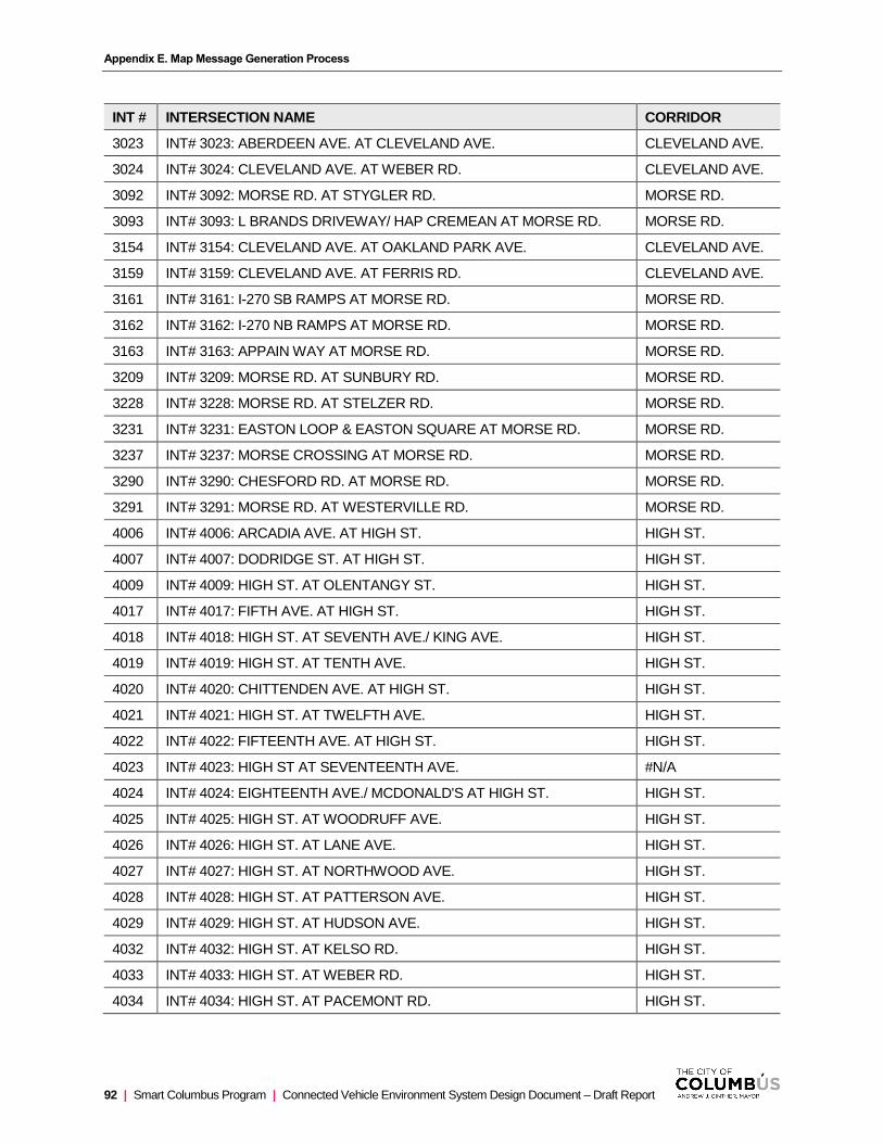
Appendix E. Map Message Generation Process
92 | Smart Columbus Program | Connected Vehicle Environment System Design Document – Draft Report
INT # INTERSECTION NAME CORRIDOR
3023 INT# 3023: ABERDEEN AVE. AT CLEVELAND AVE. CLEVELAND AVE.
3024 INT# 3024: CLEVELAND AVE. AT WEBER RD. CLEVELAND AVE.
3092 INT# 3092: MORSE RD. AT STYGLER RD. MORSE RD.
3093 INT# 3093: L BRANDS DRIVEWAY/ HAP CREMEAN AT MORSE RD. MORSE RD.
3154 INT# 3154: CLEVELAND AVE. AT OAKLAND PARK AVE. CLEVELAND AVE.
3159 INT# 3159: CLEVELAND AVE. AT FERRIS RD. CLEVELAND AVE.
3161 INT# 3161: I-270 SB RAMPS AT MORSE RD. MORSE RD.
3162 INT# 3162: I-270 NB RAMPS AT MORSE RD. MORSE RD.
3163 INT# 3163: APPAIN WAY AT MORSE RD. MORSE RD.
3209 INT# 3209: MORSE RD. AT SUNBURY RD. MORSE RD.
3228 INT# 3228: MORSE RD. AT STELZER RD. MORSE RD.
3231 INT# 3231: EASTON LOOP & EASTON SQUARE AT MORSE RD. MORSE RD.
3237 INT# 3237: MORSE CROSSING AT MORSE RD. MORSE RD.
3290 INT# 3290: CHESFORD RD. AT MORSE RD. MORSE RD.
3291 INT# 3291: MORSE RD. AT WESTERVILLE RD. MORSE RD.
4006 INT# 4006: ARCADIA AVE. AT HIGH ST. HIGH ST.
4007 INT# 4007: DODRIDGE ST. AT HIGH ST. HIGH ST.
4009 INT# 4009: HIGH ST. AT OLENTANGY ST. HIGH ST.
4017 INT# 4017: FIFTH AVE. AT HIGH ST. HIGH ST.
4018 INT# 4018: HIGH ST. AT SEVENTH AVE./ KING AVE. HIGH ST.
4019 INT# 4019: HIGH ST. AT TENTH AVE. HIGH ST.
4020 INT# 4020: CHITTENDEN AVE. AT HIGH ST. HIGH ST.
4021 INT# 4021: HIGH ST. AT TWELFTH AVE. HIGH ST.
4022 INT# 4022: FIFTEENTH AVE. AT HIGH ST. HIGH ST.
4023 INT# 4023: HIGH ST AT SEVENTEENTH AVE. #N/A
4024 INT# 4024: EIGHTEENTH AVE./ MCDONALD'S AT HIGH ST. HIGH ST.
4025 INT# 4025: HIGH ST. AT WOODRUFF AVE. HIGH ST.
4026 INT# 4026: HIGH ST. AT LANE AVE. HIGH ST.
4027 INT# 4027: HIGH ST. AT NORTHWOOD AVE. HIGH ST.
4028 INT# 4028: HIGH ST. AT PATTERSON AVE. HIGH ST.
4029 INT# 4029: HIGH ST. AT HUDSON AVE. HIGH ST.
4032 INT# 4032: HIGH ST. AT KELSO RD. HIGH ST.
4033 INT# 4033: HIGH ST. AT WEBER RD. HIGH ST.
4034 INT# 4034: HIGH ST. AT PACEMONT RD. HIGH ST.
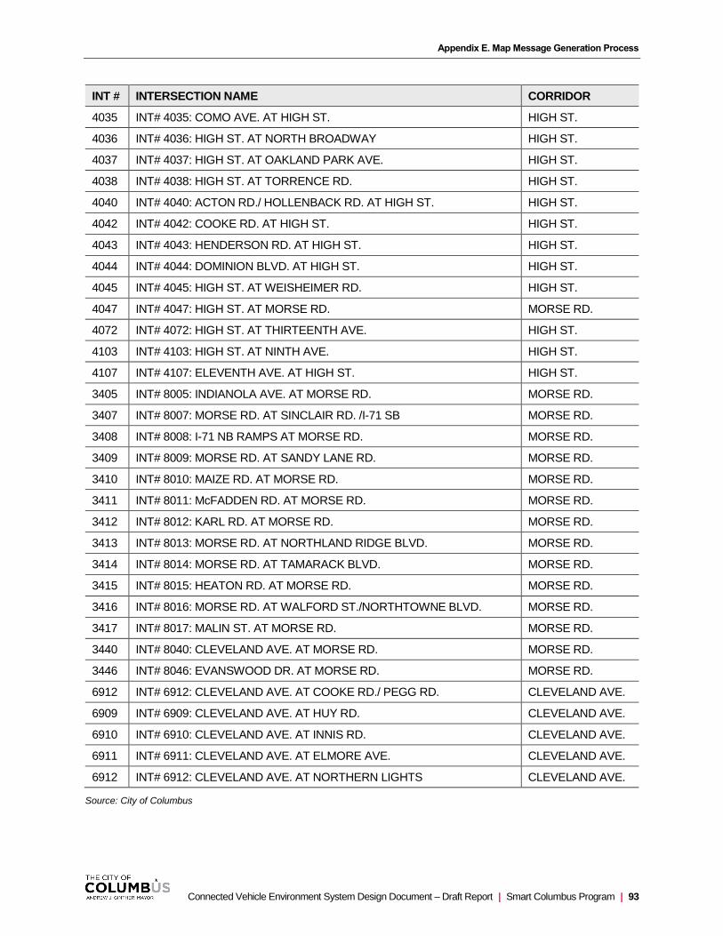
Appendix E. Map Message Generation Process
Connected Vehicle Environment System Design Document – Draft Report | Smart Columbus Program | 93
INT # INTERSECTION NAME CORRIDOR
4035 INT# 4035: COMO AVE. AT HIGH ST. HIGH ST.
4036 INT# 4036: HIGH ST. AT NORTH BROADWAY HIGH ST.
4037 INT# 4037: HIGH ST. AT OAKLAND PARK AVE. HIGH ST.
4038 INT# 4038: HIGH ST. AT TORRENCE RD. HIGH ST.
4040 INT# 4040: ACTON RD./ HOLLENBACK RD. AT HIGH ST. HIGH ST.
4042 INT# 4042: COOKE RD. AT HIGH ST. HIGH ST.
4043 INT# 4043: HENDERSON RD. AT HIGH ST. HIGH ST.
4044 INT# 4044: DOMINION BLVD. AT HIGH ST. HIGH ST.
4045 INT# 4045: HIGH ST. AT WEISHEIMER RD. HIGH ST.
4047 INT# 4047: HIGH ST. AT MORSE RD. MORSE RD.
4072 INT# 4072: HIGH ST. AT THIRTEENTH AVE. HIGH ST.
4103 INT# 4103: HIGH ST. AT NINTH AVE. HIGH ST.
4107 INT# 4107: ELEVENTH AVE. AT HIGH ST. HIGH ST.
3405 INT# 8005: INDIANOLA AVE. AT MORSE RD. MORSE RD.
3407 INT# 8007: MORSE RD. AT SINCLAIR RD. /I-71 SB MORSE RD.
3408 INT# 8008: I-71 NB RAMPS AT MORSE RD. MORSE RD.
3409 INT# 8009: MORSE RD. AT SANDY LANE RD. MORSE RD.
3410 INT# 8010: MAIZE RD. AT MORSE RD. MORSE RD.
3411 INT# 8011: McFADDEN RD. AT MORSE RD. MORSE RD.
3412 INT# 8012: KARL RD. AT MORSE RD. MORSE RD.
3413 INT# 8013: MORSE RD. AT NORTHLAND RIDGE BLVD. MORSE RD.
3414 INT# 8014: MORSE RD. AT TAMARACK BLVD. MORSE RD.
3415 INT# 8015: HEATON RD. AT MORSE RD. MORSE RD.
3416 INT# 8016: MORSE RD. AT WALFORD ST./NORTHTOWNE BLVD. MORSE RD.
3417 INT# 8017: MALIN ST. AT MORSE RD. MORSE RD.
3440 INT# 8040: CLEVELAND AVE. AT MORSE RD. MORSE RD.
3446 INT# 8046: EVANSWOOD DR. AT MORSE RD. MORSE RD.
6912 INT# 6912: CLEVELAND AVE. AT COOKE RD./ PEGG RD. CLEVELAND AVE.
6909 INT# 6909: CLEVELAND AVE. AT HUY RD. CLEVELAND AVE.
6910 INT# 6910: CLEVELAND AVE. AT INNIS RD. CLEVELAND AVE.
6911 INT# 6911: CLEVELAND AVE. AT ELMORE AVE. CLEVELAND AVE.
6912 INT# 6912: CLEVELAND AVE. AT NORTHERN LIGHTS CLEVELAND AVE.
Source: City of Columbus
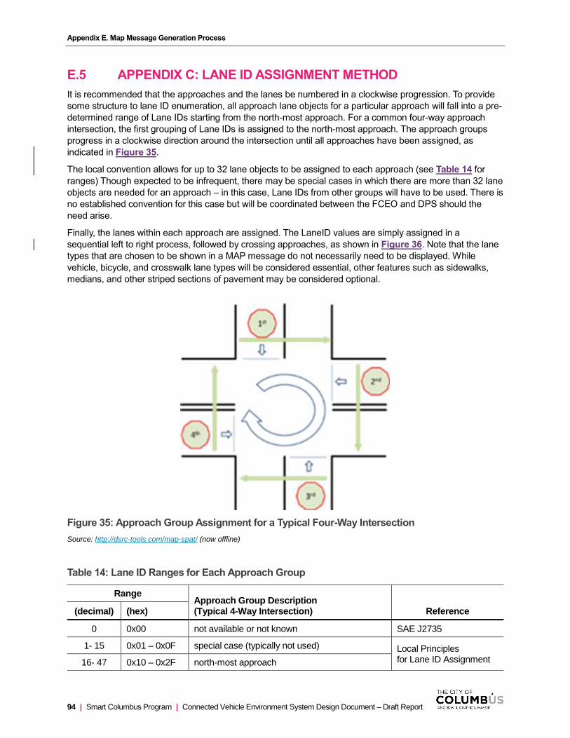
Appendix E. Map Message Generation Process
94 | Smart Columbus Program | Connected Vehicle Environment System Design Document – Draft Report
E.5 APPENDIX C: LANE ID ASSIGNMENT METHOD
It is recommended that the approaches and the lanes be numbered in a clockwise progression. To provide
some structure to lane ID enumeration, all approach lane objects for a particular approach will fall into a pre-
determined range of Lane IDs starting from the north-most approach. For a common four-way approach
intersection, the first grouping of Lane IDs is assigned to the north-most approach. The approach groups
progress in a clockwise direction around the intersection until all approaches have been assigned, as
indicated in Figure 35.
The local convention allows for up to 32 lane objects to be assigned to each approach (see Table 14 for
ranges) Though expected to be infrequent, there may be special cases in which there are more than 32 lane
objects are needed for an approach – in this case, Lane IDs from other groups will have to be used. There is
no established convention for this case but will be coordinated between the FCEO and DPS should the
need arise.
Finally, the lanes within each approach are assigned. The LaneID values are simply assigned in a
sequential left to right process, followed by crossing approaches, as shown in Figure 36. Note that the lane
types that are chosen to be shown in a MAP message do not necessarily need to be displayed. While
vehicle, bicycle, and crosswalk lane types will be considered essential, other features such as sidewalks,
medians, and other striped sections of pavement may be considered optional.
Figure 35: Approach Group Assignment for a Typical Four-Way Intersection
Source: http://dsrc-tools.com/map-spat/ (now offline)
Table 14: Lane ID Ranges for Each Approach Group
Range Approach Group Description (Typical 4-Way Intersection) Reference (decimal) (hex)
0 0x00 not available or not known SAE J2735
1- 15 0x01 – 0x0F special case (typically not used) Local Principles for Lane ID Assignment 16- 47 0x10 – 0x2F north-most approach

Appendix E. Map Message Generation Process
Connected Vehicle Environment System Design Document – Draft Report | Smart Columbus Program | 95
Range Approach Group Description (Typical 4-Way Intersection) Reference (decimal) (hex)
48- 79 0x30 – 0x4F east approach (or next clockwise approach)
80-111 0x50 – 0x6F south approach (or next clockwise approach)
112-143 0x70 – 0x8F west approach (or next clockwise approach)
144-175 0x90 – 0xAF other approach (or next clockwise approach)
176-207 0xB0 – 0xCF other approach (or next clockwise approach)
208-239 0xD0 – 0xEF other approach (or next clockwise approach)
240-254 0xF0 – 0xFE flyover approaches
255 0xFF reserved for future use SAE J2735
Source: City of Columbus
Figure 36: Lane ID Assignments for Each Approach Group
Note: Perspective oriented in the outbound/egress direction of the approach.
Source: http://dsrc-tools.com/map-spat/ (now offline)

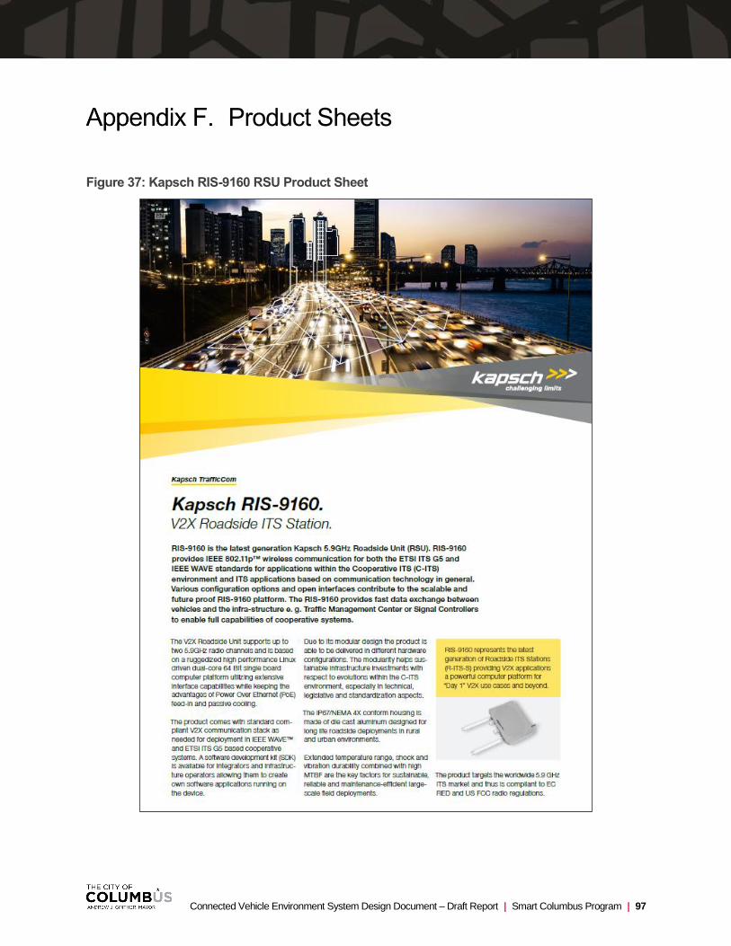
Connected Vehicle Environment System Design Document – Draft Report | Smart Columbus Program | 97
Product Sheets
Figure 37: Kapsch RIS-9160 RSU Product Sheet

Appendix F. Product Sheets
98 | Smart Columbus Program | Connected Vehicle Environment System Design Document – Draft Report

Appendix F. Product Sheets
Connected Vehicle Environment System Design Document – Draft Report | Smart Columbus Program | 99
Figure 38: Danlaw RouteLink RSU Product Sheet
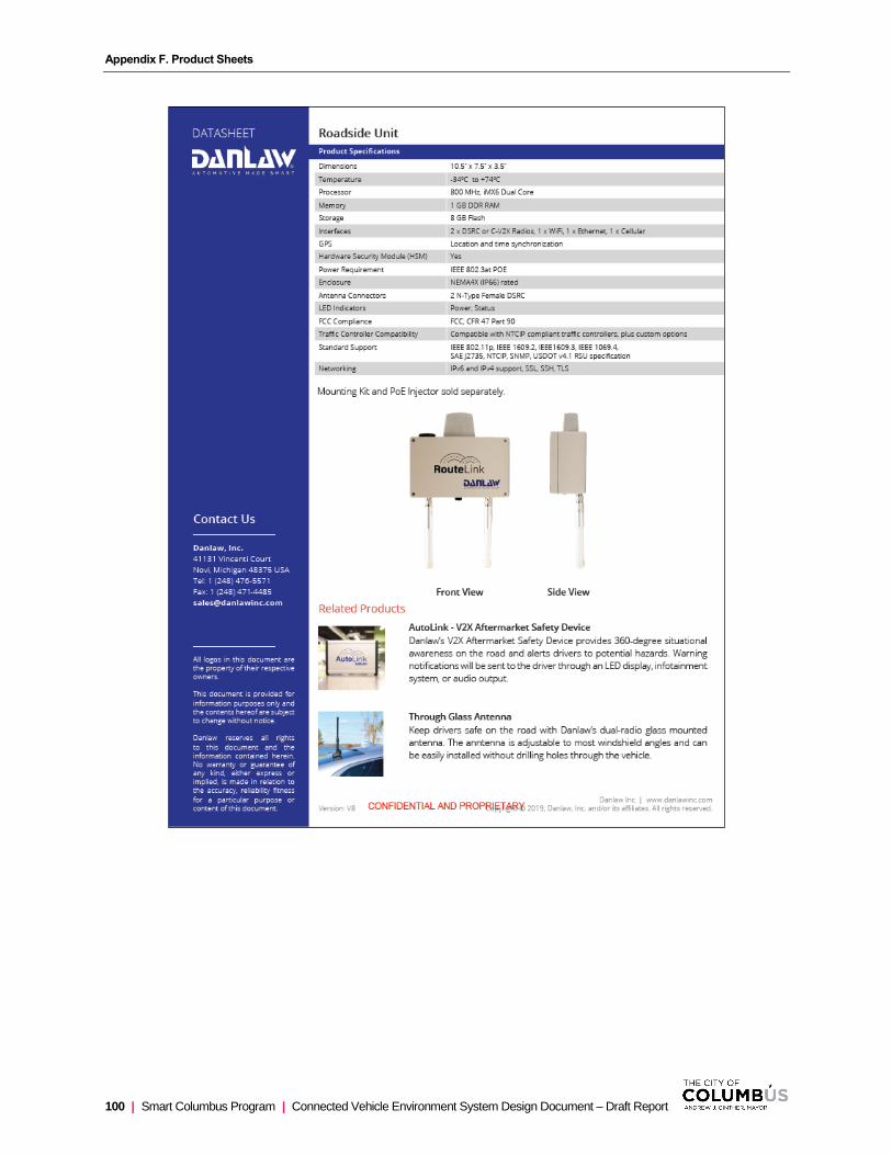
Appendix F. Product Sheets
100 | Smart Columbus Program | Connected Vehicle Environment System Design Document – Draft Report

Appendix F. Product Sheets
Connected Vehicle Environment System Design Document – Draft Report | Smart Columbus Program | 101
Figure 39: MOXA UC-8100 Product Sheet

Appendix F. Product Sheets
102 | Smart Columbus Program | Connected Vehicle Environment System Design Document – Draft Report

Appendix F. Product Sheets
Connected Vehicle Environment System Design Document – Draft Report | Smart Columbus Program | 103
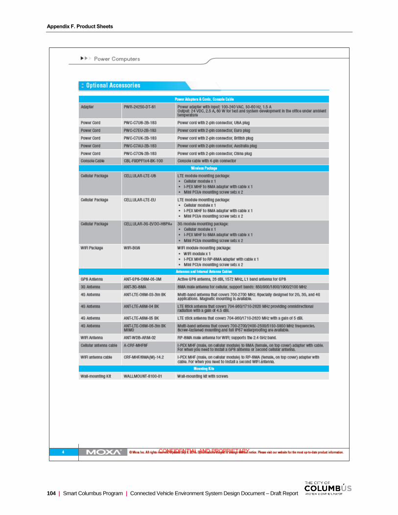
Appendix F. Product Sheets
104 | Smart Columbus Program | Connected Vehicle Environment System Design Document – Draft Report

Appendix F. Product Sheets
Connected Vehicle Environment System Design Document – Draft Report | Smart Columbus Program | 105
Figure 40: MobileMark DSRC Antenna Product Sheet

Appendix F. Product Sheets
106 | Smart Columbus Program | Connected Vehicle Environment System Design Document – Draft Report
Figure 41: QVT-14 GPS Antenna Product Sheet

Appendix F. Product Sheets
Connected Vehicle Environment System Design Document – Draft Report | Smart Columbus Program | 107

Appendix F. Product Sheets
108 | Smart Columbus Program | Connected Vehicle Environment System Design Document – Draft Report
Figure 42: PD-9001 GI/DC POE Product Sheet

Appendix F. Product Sheets
Connected Vehicle Environment System Design Document – Draft Report | Smart Columbus Program | 109
Figure 43: Sensor Mount Product Sheet
Appendix F. Product Sheets
110 | Smart Columbus Program | Connected Vehicle Environment System Design Document – Draft Report
Figure 44: Heads-Up Display Specification
Figure 45: Rear-View Mirror Specification

Connected Vehicle Environment System Design Document – Draft Report | Smart Columbus Program | 111
Version History
Table 15: Version History
Version Number Date Author(s), Agency Summary of Changes
0.1 5/8/19 WSP Initial Version for Stakeholder Review
0.2 5/24/19 WSP Draft update, Stakeholder comments addressed
1.0 5/28/18 WSP Final Version of Draft
2.0 10/11/19 WSP Updated with Kapsch and Siemens input.


![Progressive Components - CVe Monitor Initialization...CVe Connected By: Sofia Romano Company: Gallo Pumps Reason for connecting the CVe (Check all that apply): C] Part Revision Change](https://static.fdocuments.in/doc/165x107/61301d501ecc51586943e340/progressive-components-cve-monitor-initialization-cve-connected-by-sofia.jpg)