Polypyrrole-incorporated conductive hyaluronic acid hydrogels ...

i
CONJUGATED POLYMERS BASED on POLYFLUORENE DERIVATIVES and
POLYPYRROLE
A THESIS
SUBMITTED TO THE DEPARTMENT OF CHEMISTRY
AND THE INSTITUTE OF ENGINEERING AND SCIENCES
OF BILKENT UNIVERSITY
IN PARTIAL FULFILLMENT OF THE REQUIREMENTS
FOR THE DEGREE OF
MASTER OF SCIENCE
By
ÜNSAL KOLDEMĐR
JULY 2007

ii
I certify that I have read this thesis and in my opinion it is fully adequate, in scope
and in quality, as a thesis of the degree of Master of Science
Asst. Prof. Dr. Dönüş Tuncel
I certify that I have read this thesis and in my opinion it is fully adequate, in scope
and in quality, as a thesis of the degree of Master of Science
Assoc. Prof. Dr. Ulrike Salzner
I certify that I have read this thesis and in my opinion it is fully adequate, in scope
and in quality, as a thesis of the degree of Master of Science
Prof. Dr. Günay Kibarer

iii
I certify that I have read this thesis and in my opinion it is fully adequate, in scope
and in quality, as a thesis of the degree of Master of Science
Asst. Prof. Dr. Volkan Demir
I certify that I have read this thesis and in my opinion it is fully adequate, in scope
and in quality, as a thesis of the degree of Master of Science
Asst. Prof. Dr. Emrah Özensoy
Approved for the Institute of Engineering and Sciences
Prof. Dr. Mehmet Baray
Director of Institute of Engineering and Sciences

iv
ABSTRACT
CONJUGATED POLYMERS BASED on POLYFLUORENE DERIVATIVES and
POLYPYRROLE
ÜNSAL KOLDEMĐR
M.S. in Chemistry
Supervisor: Assist. Prof. Dr. Dönüş Tuncel
July 2007
In this thesis, a series of polyfluorene based copolymers have been prepared via
Suzuki Coupling for use in light emitting diodes (LEDs). Polyfluorene based
polymers are synthesized from different monomers. These polymers are
characterized with spectroscopic techniques including FT-IR, UV-VIS, Fluorescence
and 1H, 13C NMR.
Conjugated polymers are attractive chemical structures inherently allowing charge
transport. However, in the solid state, conjugated polymers lack stability and form
aggregates. To overcome this problem, conjugated polymers can be converted to
insulated molecular wires. This can be achieved by separation of the conjugated
polymer chains by a macrocycle.
In this study, encapsulation of conjugated polymers is tried with two methods. First
method is to encapsulate the polymer main chain by macrocycles. Polypyrrole based
polypseudorotaxane is prepared in this way. Pyrrole is complexed with the
cucurbit[6]uril (CB(6)) and following chemical oxidation by FeCl3 in acidic medium
yields the desired polypseudorotaxane. Spectroscopic investigations such as FT-IR,
UV-VIS, Fluorescence and 1H-NMR confirm the formation of polypyrrole based
polypseudorotaxane.

v
The second method involves the rotaxanation of the polymer side chains. For this
purpose, fluorene based monomers are chosen because the 9th position of fluorene
can be easily functionalized. After attaching suitable groups to the 9th position of
fluorene, the rotaxane formation was attempted via 1,3 dipolar cycloaddition in the
presence of CB(6).
A white light emitting diode is prepared using a hybrid inorganic and organic
material based system. Prepared conjugated polymers were used in white light
generation. Good results are obtained with high CRI indices. Also the thermal
stability of the conjugated polymers is studied by FT-IR, UV-VIS and Fluorescence
spectroscopic techniques under heat exposure.
Keywords: Pseudopolyrotaxanes, cucurbit[6]uril, Suzuki Coupling, conjugated
polymers, polyfluorene, polypyrrole, white light emitting diode.

vi
ÖZET
POLĐFLOREN TÜREVLERĐ ve POLĐPĐROL TABANLI KONJUGE
POLĐMERLER
ÜNSAL KOLDEMĐR
Kimya Bölümü Yüksek Lisans Tezi
Tez Yöneticisi: Doç. Dr. Dönüş Tuncel
Temmuz 2007
Bu tezde, ışık yayan diyotlarda kullanılması amacıyla Suzuki Birleştirme yöntemi ile
bir seri polifloren tabanlı kopolimerler hazırlanmıştır. Polifloren tabanlı polimerler
farklı bant aralığına sahip monomerlerden sentezlenmiştir. Bu polimerler FT-IR,
UV-VIS, Floresans ve 1H, 13C NMR spektroskopi yöntemleri ile analiz ve
karakterize edilmiştir.
Konjüge polimerler doğal olarak yük taşıyabildiklerinden çok ilgi çekicidir. Ama,
katı halde, konjüge polimerler kararlılıklarını kaybedip bir araya toplanırlar. Bu
sorunu aşmak için, konjüge polimerler molekül düzeyde izole olmuş tel haline
getirilebilir. Bunu sağlamak için, konjüge polimerler, büyük içi boş kovan yapılarla
sarmalanır.
Bu çalışmada, konjüge polimerlerin sarmalanması iki metod izlenerek yapılmıştır.
Đlk metodda, polimerin temel zincirleri büyük içi boş kovan yapılar içine
sokulmuştur. Polipirol tabanlı südopolirotaksanlar bu yöntemle hazırlanmıştır. Pirol,
CB(6) ile kompleks oluşturduktan sonra asidik ortamda FeCl3 ile kimyasal olarak
yükseltgenerek istenilen südopolirotaksan üretilmiştir. FT-IR, UV-VIS, Floresans ve 1H-NMR spektroskopi yöntemleri polipirol tabanlı südopolirotaksan oluşumunu
kanıtlar.

vii
Đkinci metodda ise, polimerlere bağlanmış yan zincirlerin rotaksanlanması vardır. Bu
amaçla, floren tabanlı monomerler seçilmiştir. Çünkü florenlerin 9. pozisyonuna
istenilen fonksiyonel gruplar kolayca eklenebilir. Florenin 9 pozisyonuna uygun
gruplar eklendikten sonra, rotaksan oluşumu,CB(6)’nın katalizlediği 1,3-dipolar
katılma reaksiyonu kullanılarak denenmiştir.
Beyaz ışık diyotu inorganic-organik tabanlı iki malzemeden oluşan melez sistem ile
hazırlanmıştır. Hazırlanan polimerler beyaz ışık üretiminde kullanılmıştır. Yüksek
CRI indisli sonuçlar elde edilmiştir. Ayrıca, konjüge polimerlerin sıcaklığa maruz
bırakıldıklarındaki kararlılılıkları FT-IR, UV-VIS ve Florasans spektroskopi
yöntemleri ile incelenmiştir.
Anahtar Kelimeler: Südopolirotaksanlar, kukurbit[6]yuril(CB6), Suzuki
Birleştirme Yöntemi, konjüge polimerler, polifloren, polipirol, beyaz ışık yayan
diyot.

viii
ACKNOWLEDGEMENT
I would like to express my sincere appreciation to my advisor Assist. Prof. Dr.
Dönüş Tuncel for her clear guidance, insight, encouragement and supervision
throughout the research.
I am thankful to Prof. Dr. Günay Kibarer, Assoc. Prof. Dr. Ulrike Salzner, Asst.
Prof. Dr. Emrah Özensoy and Asst. Prof. Dr. Hilmi Volkan Demir for reading my
thesis and their valuable feedbacks.
I wish to thank Ali Turan Görgü, Dr. Fikret Koç for their valuable comments and
encouragement.
I would like to express my special thanks to my roommate, Levent Subaşı for his
understanding throughout my studies.
I want to send my sincere thanks to Hasan Burak Tiftik, Oğuzhan Çelebi, Mustafa
Fatih Genişel, Sedat Nizamoğlu, Adnan Hazar, Đ. Erkin Gönenli, Olga Samarskaya,
Đbrahim Karaman, Caner Ünlü, Abidin Balan, Đbrahim Hocaoğlu, Emine Yiğit, and
all present and former members of Bilkent University Chemistry Department for
their patience and kind supports during my study.
Special thanks due to Fatma Ayhan for her deepest love, never ending supports.
Lastly, I am grateful to my parents and my sister who encouraged and listened to
me throughout my studies.

ix
TABLE OF CONTENTS
CHAPTER 1. INTRODUCTION…………………………………………………1
1.1 General Considerations………………………………………………………..1
1.2 The Importance of π Bonding…………………………………………………2
1.3 LED Structure………………………………………………………………….3
1.4 Polyfluorene Family……………………………………………………………6
1.5 Fluorescence Quenching……………………………………………………….7
1.6 Quenching Mechanisms in Polyfluorenes…………………………………….8
1.7 Insulated Molecular Wires……………………………………………………10
1.7.1 Zeolite Hosts………………………………………………...…………10
1.7.2 Layered Materials……………………..………………………………11
1.7.3 Rotaxanes……………………………………….……………….……..12
1.7.4 Dendronized Conjugated Polymers…………………………..………16
1.8 Objective of the Study……………………………………………….…...……18
1.9 Cucurbit[6]uril…………………...……………………………………………19
1.10 White Light Generation using Polymers...…………………………………20
CHAPTER 2. RESULTS and DISCUSSION………..……………...…………..23
2.1 Synthesis and characterization of monomers and polymers ……………...24
2.1.1 Synthesis and Characterization of 2,7-dibromo-9,9-bis-(6-bromo-
hexyl)-9H-fluorene (1) …………………………………................................26
2.1.2 Synthesis and Characterization of 2,7-Dibromo-9,9-bis-(3-bromo-
propyl)-9H-fluorene (2)………………...……………………………………28
2.1.3 Synthesis of Azidoethylamine................................................................29
2.1.4 Towards the Synthesis of Boronic Ester Derivatives………….….....31
2.1.5 Synthesis and Characterization of of poly[(9,9-Dihexyl-9H-fluorene)-
co-alt-(9,9-bis-(6-bromo-hexyl)-9H-fluorene )] (P1) ………………….......34
2.1.6 Synthesis and Characterization of poly[(9,9-Dihexyl-9H-fluorene)-co-
alt-(9,9-bis-(6-azido-hexyl)-9H-fluorene )] (P2)……………………………37
2.1.7 Towards functionalization of P1 and P2 ………….…….…..……….40

x
2.1.8 Synthesis and Characterization of poly[9,9-bis-(6-bromo-hexyl)-9H-
fluorene-co-1,4-phenylene] (P3)………………………………………….....43
2.1.9 Synthesis and Characterization of poly[9,9-bis-(6-azido-hexyl)-9H-
fluorene-co-1,4-phenylene] (P4)…………………………..………………...46
2.1.10 Synthesis and Characterization of poly[9,9-bis-(6-bromo-hexyl) 9H-
fluorene-co-2,5-thienylene] (P5)…………………………………….……...49
2.1.11 Synthesis and Characterization of 9, 9-bis-(6-azido-hexyl)-2,7-
dibromo-9H-fluorene (3)……………………………………………...……..53
2.1.12 Synthesis of {6-[2,7-dibromo-9-(6-prop-2-ynylamino-hexyl)-9H-
fluoren-9-yl]-hexyl}-prop-2-ynyl-amine 4……………………..…………...55
2.1.13 Formation of Rotaxane ……………..……………………………….56
2.1.14 Synthesis and Characterization of poly[9,9-Dihexyl-9H-fluorene]
(P6)……………………………………..……………………………………..58
2.2 White Light Generation by a Hybrid Polymer-Inorganic Device and
Investigation of the Thermal Stability and Degradation Behaviour of the
Polymer…………………………...………………………………………………..60
2.2.1 Device Fabrication………………...…………………………………...60
2.2.2 Thermal Stability and Degradation Behaviour of the
Polymers……………………………………………………..……………….63
2.3 Synthesis and Characterization of Cucurbit[6]uril Encapsulated
Polypyrrole Pseudopolyrotaxane………...………………..……………………..69
CHAPTER 3. CONCLUSION……………………………..…………………….77
CHAPTER 4. EXPERIMENTAL SECTION………………………..…………79
4.1 Synthesis of 2,7-dibromo-9,9-bis-(6-bromo-hexyl)-9H-fluorene 1……..…..79
4.2 Synthesis of 2,7-Dibromo-9,9-bis-(3-bromo-propyl)-9H-fluorene 2……….80
4.3 Synthesis of 9, 9-Bis-(6-azido-hexyl)-2,7-dibromo-9H-fluorene 3….………81
4.4 Synthesis of {6-[2,7-Dibromo-9-(6-prop-2-ynylamino-hexyl)-9H-fluoren-9-
yl]-hexyl}-prop-2-ynyl-amine 4…………………………………...………………81
4.5 Synthesis of cucurbit[6]uril……………………...……………………………82

xi
4.6 Addition of bis(pinacolato)diborane to 2,7-Dibromo-9,9-bis-(6-bromo-
hexyl)-9H-fluorene 5……………………………………………...……………….82
4.7 Synthesis of Azidoethylamine…………………...……………………………83
4.8 Synthesis of Rotaxane………………………………………..……………….83
4.9 Synthesis of poly[(9,9-Dihexyl-9H-fluorene)-co-alt-(9,9-bis-(6-bromo-hexyl)-
9H-fluorene)] P1…………………………………………………………………..84
4.10 Synthesis of poly[(9,9-Dihexyl-9H-fluorene)-co-alt-(9,9-bis-(6-azido-hexyl)-
9H-fluorene )] P2……………………………...…………………………………...85
4.11 Synthesis of poly[9,9-bis-(6-bromo-hexyl)-9H-fluorene-co-1,4-phenylene]
P3…………………………………………...………………………………………85
4.12 Synthesis of poly[9,9-bis-(6-azido-hexyl)-9H-fluorene-co-1,4-phenylene]
P4………………………………...…………………………………………………86
4.13 Synthesis of poly[9,9-bis-(6-bromo-hexyl)-9H-fluorene-co-2,5-thienylene]
P5 ………………………………………………..………………………………...87
4.14 Synthesis of poly[9,9-Dihexyl-9H-fluorene] P6…………………..………..87
4.15 Synthesis of poly[(9,9-Dihexyl-9H-fluorene)-co-alt-(9,9-bis-6-
(azidoethylamino)-hexyl-9H-fluorene )] P7……………………….…….…...….88
4.16 Synthesis of CB6-Py inclusion complex…………….……….……………..88
4.17 Polymerisation of Complex via Acid Catalysis…………….…….………..89
REFERENCES……………………………………………………………….….90

xii
LIST OF FIGURES
Fig. 1.1- Examples to conjugated polymers……………………………………...….2
Fig. 1.2- Depiction of band structure in inorganic and organic semiconductors.…...2
Fig. 1.3- Representation of a LED………………………………………………..…3
Fig. 1.4- Representations of conjugated polymers emitting specific colors…...…....5
Fig. 1.5- Polyfluorene homopolymer and copolymer………….…..………………..7
Fig. 1.6- Jablonski energy diagram…………..……………………………………...8
Fig. 1.7- The possible mechanisms that cause green emission………..…………….9
Fig. 1.8- Representation of a zeolite host……………………………...…………...11
Fig. 1.9- Illustration of the structures for pseudorotaxane, polypseudorotaxane,
rotaxane, polyrotaxane……………………………………………..………………13
Fig. 1.10- Representation of β-cyclodextrin………………………….....…………13
Fig. 1.11- Representation of polyaniline and prepared insulated molecular wire.....14
Fig. 1.12- Polyfluorene based polyrotaxane…………………...…………………...16
Fig. 1.13- Representation of dendrimer structure growing after 4 generations….....16
Fig. 1.14- Polyfluorene with Mullen type dendrons………………………………..17
Fig. 1.15- Representation of π-π stacking between polymer chains (a) and CB[6]
based polyfluorene rotaxanes (b)…………………………………...………………18
Figure 1.16- Synthesis of cucurbit[6]uril……………………………...…………...19
Figure 1.17- White luminescence from single polymer………………………...….22
Fig. 2.1- 1H-NMR Spectrum of 1 (400 MHz, CDCl3, 25 οC)……………..……….26
Fig. 2.2- 13C-NMR of 1 (100 MHz, CDCl3, 25 οC)………………………..………27
Fig. 2.3- FT-IR spectrum of 1………………………………..…………………….27
Fig. 2.4- FT-IR spectrum of 2……………………………………..……………….28
Fig. 2.5- 1H-NMR Spectrum of 2 (400 MHz, CDCl3, 25 οC)………………..…….29
Fig. 2.6- 13C-NMR of 2 (100 MHz, CDCl3, 25 οC)……………………..…………29
Fig. 2.7- FT-IR spectrum of azidoethylamine……………………..………………30
Fig. 2.8- FT-IR spectrum of 5………………………………………………..….…32
Fig. 2.9- FT-IR spectrum of 5 after recrystallization………………………..……..33
Fig. 2.10- 1H-NMR Spectrum of 5 (400 MHz, CDCl3, 25 οC)………………..…...33
Fig. 2.11- 1H-NMR spectrum of P1 (400 MHz, CDCl3, 25 οC)……………..…….35
Fig. 2.12- 13C-NMR Spectrum of P1 (100 MHz, CDCl3, 25 οC)…………………..35
xiii
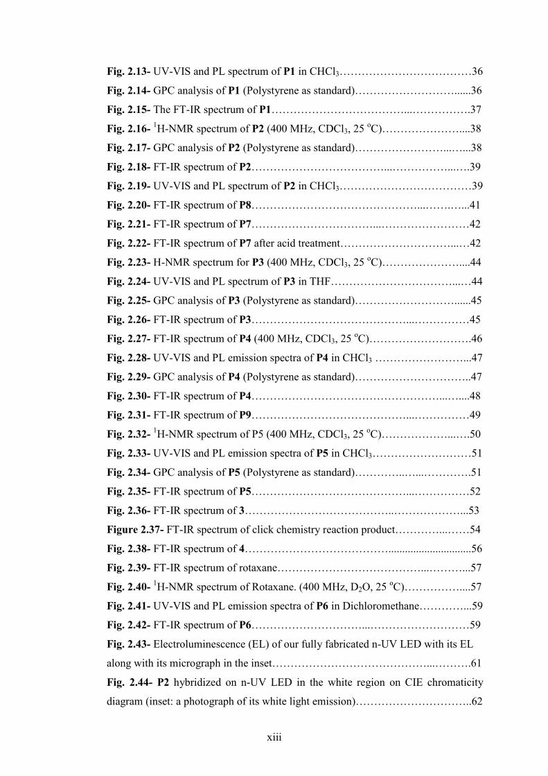
Fig. 2.13- UV-VIS and PL spectrum of P1 in CHCl3………………………………36
Fig. 2.14- GPC analysis of P1 (Polystyrene as standard)………………………......36
Fig. 2.15- The FT-IR spectrum of P1………………………………...…………….37
Fig. 2.16- 1H-NMR spectrum of P2 (400 MHz, CDCl3, 25 οC)…………………....38
Fig. 2.17- GPC analysis of P2 (Polystyrene as standard)……………………...…...38
Fig. 2.18- FT-IR spectrum of P2………………………………...……………...….39
Fig. 2.19- UV-VIS and PL spectrum of P2 in CHCl3………………………………39
Fig. 2.20- FT-IR spectrum of P8………………………………………...…….…...41
Fig. 2.21- FT-IR spectrum of P7……………………………...……………………42
Fig. 2.22- FT-IR spectrum of P7 after acid treatment…………………………...…42
Fig. 2.23- H-NMR spectrum for P3 (400 MHz, CDCl3, 25 οC)…………………....44
Fig. 2.24- UV-VIS and PL spectrum of P3 in THF……………………………...…44
Fig. 2.25- GPC analysis of P3 (Polystyrene as standard)………………………......45
Fig. 2.26- FT-IR spectrum of P3……………………………………...……………45
Fig. 2.27- FT-IR spectrum of P4 (400 MHz, CDCl3, 25 οC)……………………….46
Fig. 2.28- UV-VIS and PL emission spectra of P4 in CHCl3 ……………………...47
Fig. 2.29- GPC analysis of P4 (Polystyrene as standard)…………………………..47
Fig. 2.30- FT-IR spectrum of P4……………………………………………...…....48
Fig. 2.31- FT-IR spectrum of P9……………………………………...……………49
Fig. 2.32- 1H-NMR spectrum of P5 (400 MHz, CDCl3, 25 οC)………………...….50
Fig. 2.33- UV-VIS and PL emission spectra of P5 in CHCl3………………………51
Fig. 2.34- GPC analysis of P5 (Polystyrene as standard)…………..…...………….51
Fig. 2.35- FT-IR spectrum of P5……………………………………...……………52
Fig. 2.36- FT-IR spectrum of 3…………………………………..………………...53
Figure 2.37- FT-IR spectrum of click chemistry reaction product…………...……54
Fig. 2.38- FT-IR spectrum of 4…………………………………..............................56
Fig. 2.39- FT-IR spectrum of rotaxane…………………………………...………...57
Fig. 2.40- 1H-NMR spectrum of Rotaxane. (400 MHz, D2O, 25 οC)……………....57
Fig. 2.41- UV-VIS and PL emission spectra of P6 in Dichloromethane…………...59
Fig. 2.42- FT-IR spectrum of P6…………………………...………………………59
Fig. 2.43- Electroluminescence (EL) of our fully fabricated n-UV LED with its EL
along with its micrograph in the inset……………………………………...……….61
Fig. 2.44- P2 hybridized on n-UV LED in the white region on CIE chromaticity
diagram (inset: a photograph of its white light emission)…………………………..62

xiv
Fig. 2.45- (a)In-situ FT-IR measurement of P2 under heat exposure, (b)Inset
between 2300 cm -1 and 1500 cm -1………………………………………...……...64
Fig. 2.46- In-situ PL measurement of P2 under heat exposure………………….....65
Fig. 2.47- In-situ UV-VIS measurement of P2 under heat exposure……………….66
Fig. 2.48- In-situ PL measurement of P1 under heat exposure………………...…..67
Fig. 2.49- In-situ PL measurement of P6 under heat exposure……………...……..68
Fig. 2.50 - 1H-NMR spectrum (400 MHz, 0.2 M NaCl in D2O, 25 οC) of CB6-
pyrrole inclusion complex…………………...……………………………………...71
Fig. 2.51- Ball-and-stick model of CB6-encapsulated polypyrrole and its 1H-NMR
spectrum (400 MHz, DMSO/D2O, 25 οC)………………………………...………..71
Fig. 2.52- FT-IR spectrum of CB6-encapsulated polypyrrole………………...…...73
Fig. 2.53- UV-VIS spectrum of CB6-encapsulated polypyrrole in 6N HCl
solution………………………………………………………………………...……74
Fig. 2.54- PL spectra of CB6-encapsulated polypyrrole in 6M HCl solution……. 75
Fig. 2.55- (a) The acidic solution of CB6-encapsulated polypyrrole is light brown
and exhibits a green PL under irradiation with UV-light; (b) Polypyrrole (black
powder) and CB6-encapsulated polypyrrole (salmon powder)………………….....75
Fig. 2.56- Powder XRD patterns of a) CB6-encapsulated polypyrrole, b) CB6, c)
polypyrrole………………………………………………………………………….76

xv
LIST OF SCHEMES
Scheme 1.1- The synthesis of PPV………………………………...……….………..4
Scheme 1.2- The synthetic route for the prepared PANI-MMC nanocomposite and
depiction of the extended polymer......……………………………...………………12
Scheme 1.3- The synthesis of polythiophene based
polypseudorotaxane…………...…………………………………………….……...14
Scheme 1.4- The synthesis of dendronised fluorene monomer…………………….17
Scheme 1.5- 1,3-dipolar cycloaddition between azide and alkyne groups inside
CB(6)…………………………………………………………………...…………...19
Scheme 2.1- General reaction schemes for the rotaxanation of polyfluorene’s side
chains………………………………………………...……………………………..25
Scheme 2.2- The synthesis of 1………………………………………...…………..26
Scheme 2.3- The synthesis of 2.................................................................................28
Scheme 2.4- The synthesis of azidoethylamine…………………………………….29
Scheme 2.5- The synthesis of 5.......................................……...……..…………….31
Scheme 2.6- The mechanism for Suzuki reaction…………...….………………….32
Scheme 2.7- The synthesis of P1…………………………………………………...34
Scheme 2.8- The synthesis of P2…………………………………………………...37
Scheme 2.9- The synthesis of P8…………………………………………………...40
Scheme 2.10- The synthesis of P7………………………………………………….41
Scheme 2.11- The synthesis of P3………………..………………………………...43
Scheme 2.12- The synthesis of P4………………………………………………….46
Scheme 2.13- The synthesis of P9………………………………………………….48
Scheme 2.14- The synthesis of P5………………………………………………….50
Scheme 2.15- The synthesis route of 3……………………………………………..53
Scheme 2.16- Click chemistry reaction between 3 and propargylamine…………...54
Scheme 2.17- The synthesis of 4……………………………….……………....…..55
Scheme 2.18- The synthesis of rotaxane……………………………………...……56
Scheme 2.19- The synthesis of P6………………………………………………….58
Scheme 2.20- The synthesis of the inclusion complex between CB6 and pyrrole in
0.1M NaCl solution……………………...…...……………………………………..70
Scheme 2.21- The synthesis of CB6-encapsulated polypyrrole….………...………71

xvi
LIST OF TABLES
Table 1- Chromaticity coordinates, color temperature, and color rendering index
results………………………...……………………………………………………..62

xvii
ABBREVIATIONS
13C-NMR Carbon13-Nuclear Magnetic Resonance
CDT Cambridge Display Technology
CRI Color Rendering Index
CIE Commission Internationale de l'Eclairage
CB(6) Cucurbit[6]uril
CD Cyclodextrin
CDCl3 Deuterated Chloform
D2O Deuterated Water
DMF Dimethyl Formamide
DMSO Dimethyl Sulfoxide
FT-IR Fourier Transform-Infrared
Tg Glass Transition Temperature
GPC Gel-Permeation Chromatography
HOMO Highest Occupied Molecular Orbital
IMW Isolated Molecular Wires
LED Light Emitting Diode
LUMO Lowest Unoccupied Molecular Orbital
MMC Montmorillonite Clay
Mn Number Average Molecular Weight
OLED Organic Light Emitting Diode
PANI Polyaniline
PPV Poly Para(Phenylene vinylene)
PPy Polypyrrole 1H-NMR Proton-Nuclear Magnetic Resonance
Py Pyrrole
rt Room Temperature
UV-VIS Ultra Violet-Visible
WLED White Light Emitting Diode
Mw Weight Average Molecular Weight

1
CHAPTER 1
INTRODUCTION
1.1 General Considerations:
Polymers like plastics dominate our daily life as they are light and easily
manufactured. Two cornerstone events namely, that of observation of electrical
conductivity and that of discovery of the remarkable optical properties, stimulated
research on polymers starting up new applications. Traditional polymers are treated
as insulator materials until it was seen that doped polyacetylene shows dramatic
changes in electrical conductivity.1 By doping, electrons are added or removed with
strong oxidizing or reducing agents forming polaron or soliton states causing high
electrical conductivity. Studies on the electrical conductivity properties were
followed by the research on investigation of optical properties. Besides, conjugated
polymers attracted great interest for Organic Light Emitting Diode (OLED)
applications as they show interesting optical features after the pioneer work of
Friend et. al. obtaining green-yellow light from poly(p-phenylene-vinylene) (PPV).2
Utilization of conjugated polymers is quite feasible in large-area micrometer size
devices because polymers can be processed from solution. So far applications of
conjugated polymers to display technology2,3,4,5,6 (OLED applications), solar cell
systems7 (photovoltaics), biosensors8 and lasers9,27 were presented. Because of their
inherent electrical and optical properties conjugated polymers are called organic
semiconductors. Their structural properties lead them to be comparable to inorganic
semiconductors in terms of their electrical and optical properties. Figure 1.1 shows
some examples of conjugated polymers.
**
n
Polyacetylene
S **
n
Polythiophene
N **
n
Polypyrrole
H
**n
Poly (para-phenylene)
**
n
Poly (pheylene vinylene)
**
R Rn
polyfluorene

2
Fig. 1.1- Examples of conjugated polymers
1.2 The Importance of π Bonding
The unique structure of the conjugated polymers comes from the conjugated bonds,
which are composed of alternating double and single bonds. The alternating double
and single bonds are essential to these structures. Single bonds keep the molecule
intact upon excitation of the delocalised π electrons. Delocalised π bonds form
throughout the polymer chain enhancing the conduction of the charge carriers.
Fig. 1.2- Depiction of band structure in inorganic and organic semiconductors
In a conjugated polymer, the combination of π bonding levels and π* antibonding
levels form a band structure. The bonding levels become the valence band and the
antibonding levels can be named as the conduction band. In Figure 1.2 depiction of
the band structure in an organic semiconductor is presented. The organic terms of
Highest Occupied Molecular Orbital (HOMO) and Lowest Unoccupied Molecular
Orbital (LUMO) are similar in meaning to the inorganic nomenclature of Valence
Band and Conduction Band. Excitation promotes an electron from a bonding level to
the antibonding level. This π � π* electron transition can be observed by UV
spectroscopy. The band gap, energy difference between HOMO and LUMO, of
conjugated polymers is energetically comparable to inorganic semiconductors. This
band gap has energy in the range of 1.5-4 eV.
HOMO
LUMO
Band gap
Valence Band
Conduction Band
Band gap
3
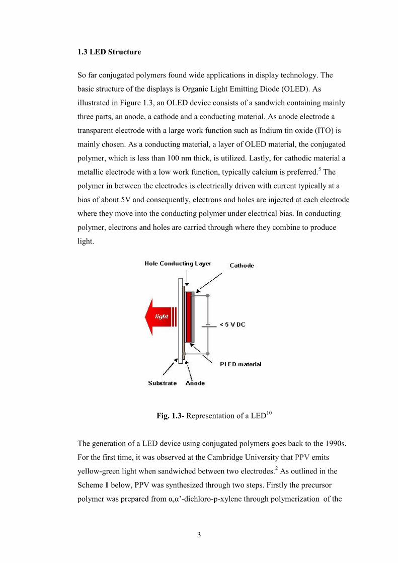
1.3 LED Structure
So far conjugated polymers found wide applications in display technology. The
basic structure of the displays is Organic Light Emitting Diode (OLED). As
illustrated in Figure 1.3, an OLED device consists of a sandwich containing mainly
three parts, an anode, a cathode and a conducting material. As anode electrode a
transparent electrode with a large work function such as Indium tin oxide (ITO) is
mainly chosen. As a conducting material, a layer of OLED material, the conjugated
polymer, which is less than 100 nm thick, is utilized. Lastly, for cathodic material a
metallic electrode with a low work function, typically calcium is preferred.5 The
polymer in between the electrodes is electrically driven with current typically at a
bias of about 5V and consequently, electrons and holes are injected at each electrode
where they move into the conducting polymer under electrical bias. In conducting
polymer, electrons and holes are carried through where they combine to produce
light.
Fig. 1.3- Representation of a LED10
The generation of a LED device using conjugated polymers goes back to the 1990s.
For the first time, it was observed at the Cambridge University that PPV emits
yellow-green light when sandwiched between two electrodes.2 As outlined in the
Scheme 1 below, PPV was synthesized through two steps. Firstly the precursor
polymer was prepared from α,α’-dichloro-p-xylene through polymerization of the

4
sulfonium salt intermediate in methanol. Dialysis with water followed by solvent
removal and subsequent vacuum evaporation yielded homogeneous PPV films. The
obtained polymer showed a strong photoluminescence band at 2.2 eV in the green-
yellow region of the spectrum.
Cl
Cl
S
MeOH, 50 oC S
Cl
Cl
-OH, H+
Dialysis
HC*
H2C *
nHS Cl
250 oC, vacuum
*
*n
PPV
Scheme 1.1- The synthesis of PPV2
This discovery led to the enormous research on the preparation of various
conjugated polymers that emit different colors from violet to red. Chemical
modifications were made on PPV based polymers for red and green emission.
However a blue light emitting polymer from PPV based polymers was not achieved
as blue light required a high band gap material. Instead polyfluorene derivatives
were used mostly for blue light emitting because they have high band gap. To tune
the band gap, different co-monomers were used. For example, coupling a thiophene
monomer with fluorene monomer generates green light in the longer wavelength of
the visible spectrum. The entire visible range can be tuned by coupling fluorene
monomers with narrow band gap comonomers as seen below in Figure 1.4 for
generation of red, orange, and white light.

5
*
C8H17 C8H17
*
n
Blue
*
C8H17 C8H17
* nS
Pale Blue
*
C8H17 C8H17
*n
Blue-violet
*
C8H17 C8H17
* nS
Green C8H17 C8H17
S S**n
Green
*
C8H17 C8H17
*
C8H17C8H17
N NSe
x yn
Orange Red
*
C8H17 C8H17
O
RO
*
OR
n
Red
*
C8H17 C8H17
***
C8H17 C8H17
n
O
n n
C8H17
C8H17
Ir
N
C8H17
C8H17
3
White
Fig. 1.4- Representations of conjugated polymers emitting specific colors

6
LEDs made of conjugated polymers attracted great attention as they combine the
properties of metals and plastics. LEDs based on conjugated polymers have basic
advantage that polymers can be easily processed from solution with spin coating or
dipping techniques. Hence the preparation of a LED becomes easier and consumes
less time. As polymers are processed from solution, they can be coated on large
areas with any shape. Thus it will be commercially possible to fabricate flexible
displays. Additionally, as polymers can be spin-coated, it will be possible to prepare
ultra thin devices. Furthermore, polymers are lightweight allowing them to be used
in portable devices. However, in display technology they must meet some
conditions such as high luminescent efficiency and long lasting light production.
Therefore, the performance is highly dependent on fluorescent quantum efficiency
of polymers. For a full color display three main colors are important; red, green, and
blue. So far as revealed by Cambridge Display Technology (CDT) company, green
and red emitting polymers showed good efficiencies and long lasting light
production to be used in a commercial electronic product. However, a stable blue
LED, offers a real challenge showing low efficiencies.10
1.4 Polyfluorene Family
Polyfluorene and its derivatives are used as blue light emitting polymers.
Polyfluorenes aided in exploding research on light emitting diodes beause they show
exceptional electrooptical properties.11 Fluorene based polymers are the most
targeted molecules because they offer strong blue fluorescence, chemical and
photochemical stability as well as good synthetic accessibility. Polyfluorenes are the
only family of conjugated polymers that span the entire visible range with high
efficiency and low operating voltage. Polyfluorenes are used in blue light emission
as they posses high band gap and its band gap can be tuned by incorporating co-
monomers to produce different colors. As mentioned above, a stable blue emission is
still under investigation. Because, when polyfluorenes are used in LEDs, they lack
stability in the solid state. They form aggregates which decreases the solubility of
the polymers. And then polyfluorenes having side chains at the C9 position show
some excimer emission.11 Excimers are dimerised units in the excited state that emit
at lower energies. This excimer emission affects the color of the emission and the

7
lifetime of the light emitting diodes. In the next section, possible causes of this
excimer emission, fluorescence quenching and related subjects will be discussed in
detail.
In Figure 1.5 structure of a polyfluorene based polymer is depicted. C9 is chemically
very important to polyfluorene family. C9 allows for certain modifications that
increase the polymers processability without disrupting the delocalization of the π
bonds. Alkyl chains added at C9 makes the polymer soluble in various organic
solvents. This is important for the preparation of the soluble polymers through
coupling reactions like Suzuki, Heck and Stille coupling. Additionally solubilizing
groups like ammonium, sulfonate, phosphonate, carboxylate can be added to this
alkyl chain pendantly to dissolve the polymer in water which is friendly to the
environment.
7 2*
R R
*
n
Polyfluorene homopolymer
1
3456
8 9
*
R R
Ar *n
Fluorene-type copolymer
Fig. 1.5- Polyfluorene homopolymer and copolymer
1.5 Fluorescence Quenching
The problem observed with the polyfluorene family is that they are not stable during
the course of functioning in the solid state. A red shift is observed, which is
undesirable. In the solid state the conjugated π bonds probably interact with other π
bonds as they stack over each other which is called aggregation. Hence two chains
behave as a single chain and emit at the longer wavelengths By this way charge
carrying pathway becomes 3-D rather nonlinear. Furthermore, fluorescence
quenching can be observed in polyfluorene family. Fluorescence quenching is
defined as the decrease in the intensity of fluorescence by a wide variety of
processes.12 Quenching can occur by deactivation of the excited state in contact with
a quencher. The relaxation process can lead to other processes without any light

8
emission. The dissipated energy for excitation of the electron can be in the form of
heat, rather than light. Figure 1.6 shows a non-radiative process. The quenching
processes and possible causes will be discussed in a detail occurring in polyfluorene
family in the following section.
Fig. 1.6- Jablonski energy diagram57
1.6 Quenching mechanisms in Polyfluorenes
Aggregation of the conjugated polymers through interchain and intrachain
interactions leads to fluorescence quenching. This process causes lower quantum
yield and a red shift in the emission. Besides red shift in the solid state, a green
emission band is observed during the course of functioning as a LED. Upon heating
or UV exposure during device operation conjugated polymer chain undergoes
irreversible changes where the characteristic blue emission loses both its intensity
and energy. Irreversible changes can occur in the chemical structure of the polymer
backbone. Some keto groups can form, in which the oxygen molecule acts as a
quencher. The characteristic blue emission decreases and a green or even yellow
low energy emission is observed at 535 nm.13 The reasons for green emission have
been intensely investigated over the past decade and still the reasons are
controversial. However, there are some explanations such as that the green emission

9
may be caused from excimer formation14, keto defect formation due to fluorenone
units13 and crosslinks15 as shown in Figure 1.7. Keto defects act as traps where the
charge carriers fall into a well. Crosslinks can distrupt the alignment of conjugation
at the backbone.
1.Free Radical and Peroxy units Formation:
R R
*
RH
*T/ O2
R R
*.R
*
Radical
O2
xy x y
R R
*
R-OO
*
xy
Peroxy Radical
2. Ketone Formation
R R
*
R-OO
*
xy
Peroxy Radical
ß-Scission
R R
**
xy
O
Fluorenone
3.Crosslinking
Fig. 1.7- The possible mechanisms that cause green emission8

10
1.7 Insulated Molecular Wires
The proposed reasons in the preceeding sections for fluorescence quenching lead to
research for preventing these causes. A widely studied idea was to separate the
polymer chains by encapsulation to prevent interchain and intrachain interactions to
make them insulated molecular wires like copper cables isolated by insulator plastic
coatings.
Conducting polymer chains were tried to be isolated from each other to enhance the
charge transport to occur along the individual chains. There have been different
approaches and various materials were utilized. This area of research has attracted
continuous attention because this approach offers some advantages. First by
encapsulation, the conducting polymer can be protected from the chemical oxidation
by oxygen. Atmospheric oxygen was shown to cause photoxidation of the polymers
thus decreasing their stability.16 Another point is that isolation of the conducting
polymer units will allow to understand the transport mechanisms occurring along the
polymer chain.
So far, conjugated polymers have been threaded into the pores of regular micro and
mesoporous solids, between the planes of layered materials and pillared clays.
Besides incorporation of the polymer into pores or to the pillared materials,
polymers were also threaded by macrocycles. The latter approach is named as
rotaxanation. Rotaxanes are interlocked molecules where an axle, the linear part, is
surrounded by macrocycles forming ion-dipole interactions or van der Waals
interactions. The following paragraphs will describe how insulated wires have been
prepared by introducing representative examples.
1.7.1 Zeolite Hosts:
Zeolites are aluminosilicate materials and their structure is composed of XO4 –n
tetrahedrons. The X atom is either aluminum or silicon. Zeolites have a microporous
structure as depicted in Figure 1.8 below.

11
Fig. 1.8- Representation of a zeolite host.
Polyaniline was incorporated into the pores of the H-zeolites. Polyaniline was
synthesized in H- zeolites in its protonated form after aniline and oxidation agent µ-
peroxo-bis(trioxosulfate) (2-) was located in the pores.17
1.7.2 Layered Materials
Layered materials like clay offer isolation of the conducting polymer chains. Though
it is not totally an encapsulation, it aids in the separation of the polymer chains.
Additionally, layers serve as a protective shealth against environment. Poly[2-
methoxy-5-(2’ethylhexyloxy)-p-phenylene vinylene] (MEH-PPV) was intercalated
into the layers of mica type silicate.18 Firstly clay was sonicated and stirred with a
solution of polymer in 1,2-dichloro ethane. The obtained product was investigated
by XRD and revealed a photoluminescence intensity increase by a factor of 9
compared to pure MEH-PPV of the same thickness.
Polyaniline (PANI) was introduced into the modified montmorillonite clay. Na+-
montmorillonite was mixed with aniline to force cation exchange and
polymerization is performed by ammonium persulftate at pH 2. The product was
characterized by FT-IR, UV spectroscopies and XRD. Wu et. al. reported the
conductivity of the prepared nanocomposite has a relatively higher conductivity if
compared to other prepared PANI/inorganic host hybrids.19 Conductivity was
enhanced as the polymer approved an extended conformation as outlined in the
scheme 2.

12
Scheme 1.2- Synthetic route for the prepared PANI-MMC nanocomposite and
depiction of the extended polymer
The same experimental approach was also tried for preparation of the polypyrrole-
clay nanocomposites using modified montmorillonite clay.20,a-b Chang et. al.
reported thermal stability of the intercalated polymer as compared to pristine
polypyrrole from the TGA analysis. To add that DSC measurements showed an
increase in the glass transition temperature (Tg) of the nanocomposite.
1.7.3 Rotaxanes
As mentioned in the previous section rotaxanes are interlocked molecules.
Rotaxanes are composed of a cyclic macrocycle threaded into a linear molecule. The
nomenclature is applied for different types of prepared interlocked structures
according to their composition. Pseudorotaxane corresponds to regular structures
where the axle is surrounded by a cyclic unit. If the former structure is confined with
bulky stopper units then it is called rotaxane. These terms can be applied to
polymers where the cyclic unit and the axle form the repeating unit. If there are
bulky stopper groups attached to the polymer chain ends then it is called
polyrotaxane. Absence of stopper groups leads to the polypseudorotaxane. These
structures are depicted in Figure 1.9.

13
pseudorotaxane polypseudorotaxane
Rotaxane polyrotaxane
Fig. 1.9- Illustration of the structures for pseudorotaxane, polypseudorotaxane,
rotaxane, and polyrotaxane
In the preparation of conjugated polyrotaxanes mainly cyclodextrins have been used
as a macrocycle. Cyclodextrins are cyclic molecules made up of glucose units. α-, β-
, γ- cyclodextrin derivatives consist of six, seven and eight glucose units
respectively. The structure of a β- CD is presented in Figure 1.10. They have
cavities in the range of 4.3 Ả to 7.4 Ả with cross sectional areas from 15 Ả2 to 43
Ả2.54
Fig. 1.10- Representation of β-cyclodextrin
This size internal cavity allows inclusion of molcules of suitable dimensions.
Furthermore, its interior is hydrophobic and the exterior part is hydrophilic. The
ability of cyclodextrin to form inclusion complexes comes from hydrophobic
interactions with the guest molecule. Cyclodextrins can assume head to tail or head
to head arrangements while packing in solid state. They are soluble in water and
organic solvents like DMSO, DMF and pyridine. Its good solubility is advantageous
for the preparation of inclusion complexes with conjugated polymers.

14
Polyaniline in its emeraldine base structure was threaded into β-cyclodextrin by Ito
and coworkers as depicted in the Figure 1.11 below.21 It was shown that
encapsulation of the polymer by cyclodextrins resulted in a rod like conformation
rather than coil conformation below 275 οK confirmed by scanning tunneling
microscope (STM) analysis. In another study, it was also shown that prepared
polypseudorotaxane was protected from the chemical oxidation by iodine.22
Fig. 1.11- Representation of polyaniline and prepared insulated molecular wire21
Encapsulated polythiophenes have been studied widely. For example, Lagrost et al.
reported the synthesis of HP-β-CD enapsulated polythiophene from
electropolymerisation of the bithiophene in aqueous solution of HP- β-CD and
LiClO4 as shown in Scheme 3 below. From spectroscopic analysis it was shown that
polymer was threaded into CD. The polypseudorotaxane showed higher solubility in
DMF (1 gL-1) when compared to polythiophene of the same chain length itself.23
Scheme 1.3- Synthesis of polythiophene based polypseudorotaxane23
Harada et al. synthesized encapsulated polythiophene starting from bithiophene and
β-CD using FeCl3 as an oxidizing agent. They also managed to obtain the crystal
structure of β-CD + bithiophene complex.24

15
Besides polypseudorotaxanes, polythiophene-based polyrotaxanes were also
synthesized by Hadziioannou and co-workers. Bithiophene+β-cyclodextrin complex
was formed in water. Hydropohic interior of the β-CD facilitated the complexation
of the hydrophobic bithiophene. After preparation of the complex, polymerisation
was performed with Ni-catalysed Yamamoto coupling reaction. At the end of the
reaction, 9-bromoantracene was provided as stopper groups. From small-angle
neutron-scattering analysis it was shown that 1.0 β-CD for each repeat unit.25
There are many examples to polythiophene-based polyrotaxanes. However, there are
only limited numbers of examples to polypyrrole-based polyrotaxanes. For example,
Ritter et al attempted to prepare an encapsulated polypyrrole. However after forming
the inclusion complex between pyrrole and CD, upon polymerisation CD unthreads
over the pyrroles and only polypyrrole is formed.26
Polyfluorenes have also been tried to be encapsulated by rotaxanation. The
preparation of an insulated polyfluorene by CD has been tried via two different
synthetic pathways. Hadziioannou and co workers utilised Ni- catalysed Yamamoto
coupling for the polymerisation of the 2-7 dibromofluorene β-CD complex obtained
from DMF. 9-bromoantracene was chosen as stopper groups to prevent the β-CD
slip off from the polymer chains.25
Anderson et al. used Suzuki coupling to prepare insulated molecular wires.28
Additionally, solubilizing ionic groups like -CO2Li were added to the alkyl chains of
fluorene units and –SO3Li were added to naphthalene stopper groups, as depicted in
Figure 1.12. Thus the solubility in water and DMSO was achieved. These ionic
groups also aided in separation of the cyclodextrins and no interaction occurs
between them. From NMR spectroscopy analysis and corresponding theoretical
study, it was found that 2.2 cyclodextrins accommodated per repeat unit of the
polymer. The rotaxanation of the polyfluorene backbone showed blue shifted
emission and high luminescence efficiency. Aggregation tendency was reduced and
reduction by impurities was prevented aiding in the chemical stability of the polymer.

16
Fig. 1.12- Polyfluorene based polyrotaxane28
1.7.4 Dendronized Conjugated Polymers
Dendrimers are large molecules that are made up a core and regularly branched
dendrons. A repeating fractal shape is characteristic with dendrimers as depicted in
Figure 1.13. As they occupy a large volume, dendrimers were utilized in site
isolation of conjugated polymer chains. Dendrimers are attached chemically to the
backbone of the conjugated polymer. As dendrimers occupy large volume they cause
separation of the polymer chains due to steric reasons. These kinds of molecules are
also named as insulated molecular wires because dendrimers are wrapping the
conjugated polymer chain.
Fig. 1.13- Representation of dendrimer structure growth after 4 generations
Dendrimers were added to various conjugated polymers. Two methods were tracked.
First method was, forming the polymer backbone from monomers and then addition
of the dendron after a chemical reaction. Steric reasons retard the addition of the
bulky dendrimers thus lowering the dendron coverage in the polymer. The second
method involved dendronized monomers coupled with other monomers to form the
polymer. For a representative study, polyfluorenes possessing the 1st,2nd and 3rd
generations of Frechet type dendrimers were obtained by Carter et. al. Monomers
containing the Frechet type dendron as seen in Schem 4, were prepared. These

17
dendronised monomers were coupled with dialkyl containing fluorene monomers
through Yamamoto and Suzuki coupling to form homopolymers and copolymers.
Especially 2nd-generation containing copolymers exhibited aggregation free solid
state spectra.29
Scheme 1.4-Synthesis of dendronised fluorene monomer29
Frechet type dendrons are flexible, however dendrimers prepared by Müllen exhibits
rigid structure. These dendrons are made up of polyphenylene dendrons as depicted
below in Figure 1.14. The dendrons form more stable linkages and cause shape
persistency.45 Polyfluorenes containing Müllen-type dendrons showed good
solubilities because of the dendrons formed from polyphenylene groups.
Furthermore, these dendrons permitted spatial control of the polymer chain and
hindered aggregation.31
**
Ph
Ph
PhPh
Ph
Ph
PhPh
n
Fig. 1.14- Polyfluorene with Mullen type dendrons31

18
1.8 Objective of the study
Our work is aimed to synthesize a series of polyfluorene based polymers for
applications in LEDs and photovoltaics. In this work, it is intended to use
supramolecular chemistry to achieve control at the molecular level to prepare
insulated molecular wires by rotaxanation or encapsulation of polymer backbone by
a macrocycle. Rotaxanation of these polymers is aimed to be done in two ways to
control the molecular structure. First is the encapsulation of the polymer backbone
with macrocyles, e.g., cucurbit[6]uril, which will be discussed in detail in the next
section. The second approach is to attach CB(6) to the modified alkyl chains added
to the C9 of the polyfluorenes. By introducing bulky CB(6) it will be probable to
distrupt the π-π stacking causing the interchain interactions. As a result, it is aimed
to prevent quenching and to increase electroluminescence efficiency.
In Figure 1.15 the rotaxanation of the conjugated polymers by CB(6) is illustrated in
comparison with the π-π stacking between the polyfluorene chains. In a, π-π
stacking is shown which causes the aggregation. In b, sepearation of the
polyfluorene chains by CB(6) macrocycles by forming polyrotaxanes.
Fig. 1.15- Representation of π-π stacking between polymer chains (a) and CB[6]
based polyfluorene rotaxanes (b)

19
1.9 Cucurbit[6]uril
The “bead” used in our work is cucurbit[6]uril which is first introduced by Behrend
et al.32 Cucurbit[6]uril is chosen as a bead for rotaxanation because of its easy
synthesis and rigid structure with a hollow core. Cucurbit[6]uril is a hexameric
symmetrical macropolycyclic compound and it is self-assembled from an acid-
catalyzed condensation reaction of formaldehyde and glycoluril.
Figure 1.16- Synthesis of cucurbit[6]uril
It has a cavity diameter of ~5.7 A0 with the occuli of diameter of ~4 A0. CB(6) has a
hydrophobic interior so hydrocarbon molecules can be easily included and the polar
carbonyl groups at the occuli forms a hydrophilic environment which aids its
solubility in aqueous medium. CB(6) can bind ions and molecules through charge-
dipole and hydrogen bonding interaction through its polar carbonyl groups. Another
remarkable feature is that it can serve readily as a catalyst. CB(6) can catalyze 1,3-
dipolar cycloaddition between azide and alkyne groups inside the cavity as depicted
in Scheme 5.
Scheme 1.5- 1,3-dipolar cycloaddition between azide and alkyne groups inside
CB(6)
CH2O
H2SO4
⇔⇔⇔⇔

20
Additionally, an important feature of the cucurbit[6]uril is that, it can host
diammonium salts very well. In 1990, Mock reported a pseudorotaxane that consist
of CB(6) as a bead and linear triamine unit, PhNH(CH2)6NH(CH2)4NH2.37 At low
pH all nitrogen atoms in the thread protonated so CB [6] bead stays at the
diprotanated diaminohexane site because they form more stable complex than with
diprotanated diaminobutane. At high pH, bead moves to diprotanated diaminobutane
site because diaminohexane group has only one protonated amino unit.
1.10 White Light Generation using Polymers
In recent years white polymer light emitting diodes (WLEDs) attracted intense
research as they offer applications in displays and lighting as lighting by
incandescent sources uses up % 40 per cent of the electricity in the domestic
buildings.33 The incandescent sources are inefficient, WLEDs provide basic
advantages like low-cost solution processing and easy manufacture. Especially
conjugated polymers used in WLEDs offer good processability, low operating
voltage, fast response times and facile color tunability over the full visible range.34
For the production of white light different strategies were undertaken. One of the
approaches is to design a multilayer device possessing two or more active layers
where each layer emits a primary color. In 2006, Forrest et. al. reported the highest
external quantum efficiency 18.7% and power efficiency of 500 cd m-2 using
phosphorescent triplet exitons for the high wavelengths and an organic polymer
acting as a singlet exciton emitter.33 This approach has obtained the highest results
for WLEDs. However, the preparation of such WLEDs is difficult as solution
processing of one layer may result in the dissolution of the other previous layers.35
Another widely studied approach is to blend two or three fluorescent polymers into a
blue emitting polymer host as a single layer. However, these types of WLEDs suffer
from phase separation during long term device operation and spectral changes over
the applied voltage resulting in unstable devices.36

21
The recent approach is to use a single polymer, compromising the three Red, Green,
Blue (RGB) emitting chromophore groups in itself. This method, though it is tedious
about the synthesis part, advantages over the other strategies yielding no phase
segregation or dissolution of other layers. The results from this approach yield lower
efficiency values if compared to other methods but easy fabrication creates a reason
of investigation. A very recent study by Luo et. al. prepared a fully conjugated
copolymer consisting of poly(9,9-dioctylfluorene) (PFO), 2,1,3-
benzothiadiazole(BT) and 4,7-bis(2-thienyl)-2,1,3-benzothiadiazole (DBT) as blue,
green and red emitting parts, respectively.35 They obtained external quantum
efficiency of 3.84% and luminescence efficiency 6.20 cdA-1 with CIE coordinates of
(0.35, 0.34). However, the synthesis is up to an optimum mixing of the green and red
units. To get a best balance between the red-green-blue emissions, the amounts of
each unit must be controlled. Thus the emission efficiency is highly dependent on
the unit composition. In addition, there is also a problem caused by the dopant
content which is less than 0.05% mol. It is almost impossible to determine an actual
composition of the copolymers. Earlier, Liu et. al. benefited the same approach using
polyfluorene backbone as a blue emitting host, 4-diphenylamino-1,8-naphtalimide
(DPAN) as a green dopant and 4,7-bis(5-(4-(N-phenyl-N-(4-
methylphenyl)amino)phenyl)-thienyl-2-)-2,1,3-benzathiadiazole (TPATBT) as a red
dopant. These additive red and green dopants are in low concentration to allow
incomplete energy transfer from the blue host to the green and red emitters. If the
dopants were used at stoichiometric proportions a complete energy transfer between
the blue host and the other emitters would occur and the last emitter will give the
only color instead of the whole color system, i.e. white. They obtained a white
luminescence with CIE coordinates (0.31, 0.34), a luminescence efficiency of 1.59
cdA-1. Lee et. al. in 2005 were the first to report their results using the blue-green-
red emitting copolymers on the single backbone. The device exhibited a maximum
brightness of 820 cdm-2 under 11 V with CIE coordinates of (0.33, 0.35). In the
same year Wang et. al. reported a single polymer by attaching a small amount of a
green emissive component to the pendant chain and incorporating a small amount of
a red emissive component into the main chain of the blue emissive polyfluorene.

22
Figure 1.17- White luminescence from single polymer38
By using a slghtly different strategy Liu et. al. realizing the same approach followed
a bit different design, rather than adding the green and red dopants into the backbone
directly, they introduced the green and red emitting dopants directly to the side chain
of the blue emitting polyfluorene backbone as seen above.38 (Figure 2.1). It is
reported that this approach has the advantage of forming an intramolecular
dopant/host system without affecting the electronic properties of the polymer
backbone. The incomplete energy transfer acts for realization the white light
emission with CIE coordinates of (0.31, 0.32). The single polymer device generates
a luminescence efficiency up to 7.3 cdA-1 and power efficiency.
Rather than using a single polymer layer, hybrid systems emerged. The hybrid
devices will be covered in detail in the following chapter.

23
CHAPTER 2
RESULTS AND DISCUSSION
This chapter consists of three main sections. In the first section, synthesis and
characterization of monomers and polymers are discussed. As mentioned in the
introduction, it is intended to prepare conjugated polymers for applications in LEDs
and photovoltaics. Furthermore these polymers were intended to be encapsulated by
cucurbit[6]uril by rotaxanation. Rotaxanation was aimed through two paths. First
was the encapsulation of the polymer backbone with cucurbit[6]uril. The second
path was to attach CB(6) to the modified alkyl chains added to the C9 of the
polyfluorenes. In the second section, the features of the prepared hybrid WLED will
be covered with an investigation of the stability and thermal degradation behaviour.
In the last section rotaxanation through the conjugated polymer backbone will be
discussed. This section compromises the results from the polypyrrole based
polypseudorotaxanes.

24
2.1 Synthesis and characterization of monomers and polymers
In this section attempts to prepare a polypsedurotaxane with fluorene based
conjugated polymer will be discussed. Here, the aim was to modify conductive light
emitting polymers through supramolecular chemistry to obtain polymers with
interesting and different properties than the parent polymers. For example, it is
possible to functionalise the C9 of blue light emitting polyfluorene through
rotaxanation using cucurbit[6]uril as a macrocycle. This will result a decrease in the
inter chain interactions and in turn, an increase in the luminescent efficiency.
For this purpose, we have tried two approaches as shown in the Scheme 2.1. First
approach involves the preparation of a series of appropriate copolymers whose side
chains allow us to carry out rotaxanation.
In the second approach, first a fluorene monomer is functionalized with a suitable
alkyne monomer. Then, by addition of azido monomer and CB(6), rotaxane is
formed via CB(6)-catalysed 1,3 dipolar cycloaddition. This rotaxane is polymerized
using Suzuki coupling conditions.

25
BrBr
1,6 Dibromohexane
BrBr
BrBr
BrBr
*
H3NN3
NH2
NH2H2N
*
NN
*
NN
N
N NH2
NH2
N N
NH3
N
NH2H2N
*
N
N
NH3
N
1
R =
B BOOO
O
B
B
HO OH
HO OHS BBOH
OH
HO
HO
R *
N3N3
* R *
NaN3
R *
H2N
Click Chem.
R *
ClCB(6)
R *
Suzuki Coupling
NH2H2N
Br Br
H3NN3
N N
NH3
N
NH2H2N
Br
N
N
NH3
N
ClCB(6)
Br
H2N
R
Suzuki Coupling
Scheme 2.1- General reaction schemes for the rotaxanation of polyfluorene’s side
chains.

26
2.1.1 Synthesis and Characterization of 2,7-dibromo-9,9-bis-(6-bromo-hexyl)-
9H-fluorene (1)
Commercially available 2-7 Dibromofluorene was treated with highly basic NaOH
solution (% 50) in DMSO in the presence of the phase transfer catalyst,
tetrabutylammonium bromide. Highly basic NaOH was used for the abstraction of
the protons at the C9 of the fluorene precursor. A nucleophilic substitution reaction
was perfomed to this C9 with 1,6 dibromohexane with a 40 % yield at room
temperature. Without supplying any inert atmosphere, side reactions were observed.
The reaction scheme is outlined below in Scheme 2.1
BrBr
1. DMSO, NaOH % 50
2. 1,6 Dibromohexane rt, 2 h, % 40
BrBr
BrBr
1
Scheme 2.2- The synthesis of 1
BrBr
BrBr
b b
c c
d de
f fa
a'
a''
g g
Fig. 2.1- 1H-NMR Spectrum of 1 (400 MHz, CDCl3, 25 οC)

27
2,7-dibromo-9,9-bis-(6-bromo-hexyl)-9H-fluorene was characterized by 1H-
NMR,13C-NMR, FT-IR spectroscopy. 1H-NMR spectrum showed multiplet at 7.2
and 7.35 ppm due to the aromatic protons. Signal at 3.34 ppm appeared as a triplet
for –CH2 protons close to bromine were deshielded because of the electronegative
bromine atom. Also multiplets at 1.95, 1.7, 1.20 and 0.65 ppm were observed for the
rest of alkyl protons.
Fig. 2.2- 13C-NMR of 1 (100 MHz, CDCl3, 25 οC)
13C-NMR showed 6 non equivalent aromatic carbon atoms at 121.9, 122.3, 126.9,
131.1, 139.9, 153.1 ppm. The carbon bonded to bromine was deshielded and
appeared at 153.1 ppm. Also, quaternary carbon at the 9th position was observed at
55.9 ppm because of the quaternary effect. The alkyl carbons appear at 23.6, 27.9,
29.1, 32.8, 33.9, 40.2 ppm because of the 6 different carbon atoms.
In the FT-IR spectrum of 1, aromatic carbon hydrogen stretching at 3025 cm-1 and
aliphatic carbon hydrogen stretchings at 2922 cm-1 are observed. The aromatic
carbon double bonds appear as a weak peak at 1598 cm-1.
3 5 0 0 3 0 0 0 2 5 0 0 2 0 0 0 1 5 0 0 1 0 0 0
0 ,0
0 ,1
0 ,2
0 ,3
0 ,4
0 ,5
Absorbance
W a v e n u m b e r ( c m- 1)
3 0 2 5
2 9 2 2
1 5 9 8
Fig. 2.3- FT-IR spectrum of 1

28
2.1.2 Synthesis and Characterization of 2,7-Dibromo-9,9-bis-(3-bromo-propyl)-
9H-fluorene (2)
BrBr
1. DMSO, NaOH % 50
2. 1,3 Dibromopropane rt, 2 h, % 6 BrBr
BrBr
2
Scheme 2.3- The synthesis of 2
The previous synthetic route (Scheme 2.1) was applied to the preparation of the
monomer 2. 1,3- dibromopropane was used for the nucleophilic substitution reaction
with a % 6 yield. (Scheme 2.2) Low yield was caused by the formation of side
products which were separated by column chromatography. The product was
characterized by 1H-NMR, 13C NMR, FT- IR spectroscopy techniques
Figure 2.4 shows the FT-IR spectrum of 2. Aromatic carbon hydrogen bond
stretchings are observed as a weak band at 3048 cm-1and the aliphatic carbon
hydrogen stretchings are seen at 2927 cm-1. The aromatic carbon double bonds at
around 1605 cm-1 are present.
3 0 0 0 2 0 0 0 1 0 0 0
0 ,0
0 ,2
0 ,4
0 ,6
0 ,8
absorbance
W a v e n u m b e r ( c m- 1)
3 0 4 8
2 9 2 7
1 6 0 5
Fig. 2.4- FT-IR spectrum of 2

29
1H-NMR spectrum showed 6 aromatic protons as a multiplet between 7.2-7.45 ppm.
The triplet at 3.05 ppm was due to the methylenic protons next to the bromine atom.
Signals at 2.06 ppm and 1.08 ppm. were seen for other alkyl protons.
Fig. 2.5- 1H-NMR Spectrum of 2 (400 MHz, CDCl3, 25 οC)
In the 13C-NMR spectrum 10 signals were observed, 6 of non equivalent aromatic
carbon atoms at δC :122.2, 122.7, 127.0, 131.7, 139.8, 151.6 and 4 signals for the
carbon atoms at δC : 27.1, 33.7, 38.7, 54.8 ppm. The quaternary carbon atom is
observed at 54.8 ppm.
Fig. 2.6- 13C-NMR of 2 (100 MHz, CDCl3, 25 οC)
2.1.3 Synthesis of Azidoethylamine43
H3N
Cl
Cl
NaN3
H2N
N3
H2O
70 oC, 2d% 67
Scheme 2.4- The synthesis of azidoethylamine

30
2-chloroethylamine hydrochloride was subjected nucleophilic substitution reaction
with sodium azide in water. Product was obtained with a % 67 yield after work-up.
The product was treated with NaOH to abstract the acidic protons and product
became soluble in organic solvents.
3 5 0 0 3 0 0 0 2 5 0 0 2 0 0 0 1 5 0 0 1 0 0 0
0
1
2
Absorbance
W a v e n u m b e r ( c m- 1)
2 1 0 2
3 3 6 9
2 9 3 6
Fig. 2.7- FT-IR spectrum of azidoethylamine
The characterization of azidoethylamine was carried out by FT-IR spectroscopy. In
the FT-IR spectrum, carbon azide stretching peak at 2102 cm -1 and aliphatic carbon-
hydrogen stretching at 2936 cm -1 were present. The primary amine was observed as
a band with a maximum at 3369 cm -1.
After preparation of the monomers, our intention was to prepare poly[2,7-Dibromo-
9,9-bis-(6-bromo-hexyl)-9H-fluorene]. We intended to do rotaxanation at the
homopolymer. For the preparation of the homopolymer corresponding boronic ester
of the monomer 1 was to be prepared. We tried various experimental methods. As an
example, bis(pinacolato)diborane addition to the monomer via Suzuki coupling will
be discussed.

31
2.1.4 Towards the synthesis of boronic ester derivatives
BrBr
BB
BrBr
BrBr
O
O O
O
PdCl2 (dppf), KOAc
5
B
BO O
O O80 oC, overnight, % 42
Scheme 2.5- The synthesis of 5
Suzuki coupling conditions were applied for the addition of bis(pinacolato)diborane
to 2,7-dibromo-9,9-bis-(6-bromo-hexyl)-9H-fluorene using potassium acetate and
Pd(II) catalyst at a catalytic amount at 80 οC. After purification by column
chromatography using cyclohexane:ethyl acetate (10:1) as an eluent the product was
obtained with a % 42 yield after recrystallisation from cyclohexane.
We applied Suzuki coupling conditions for this reaction. Suzuki coupling is widely
used to form aryl-aryl bonds.43 The precursors of the reaction are, aryl halide and
boronic acid dervative of an aryl compound in a weakly basic medium with Pd
catalysts. Pd catalyst can be used either as Pd(II) and Pd(0). Suzuki coupling can be
performed at moderate temperatures and in aqueous medium. The reaction is highly
tolerant to other groups. To increase the reactivity of boron atom a slightly basic
medium is supplied. The mechanism of the reaction involves the usage of palladium
catalyst. Firstly, aryl halide is added to the palladium catalyst via oxidative addition.
Then basic medium activates this intermediate for the reaction with aryl-boronate
compound. The last step is the releasing of the precursor palladium catalyst by
formation of the desired aryl-aryl compound via reductive elimination.

32
Scheme 2.6- Mechanism for Suzuki reaction.
5 was investigated through FT-IR and 1H NMR spectroscopy. In the FT-IR spectrum
boron-oxygen bond stretching was observed at 1380 cm -1. Also the medium peaks
for carbon-bromide bond stretching at 753 and 650 cm -1 were present. However, a
peak at 1738 cm-1 for carbonyl stretching was observed.
Fig. 2.8- FT-IR spectrum of 5
The peak at 1738 cm-1 for carbonyl stretching was thought to be from potassium
acetate or ethyl acetate residues, however the peak didn’t disappear after
recrystallisation from cyclohexane as shown in Figure 2.9.

33
3 5 0 0 3 0 0 0 2 5 0 0 2 0 0 0 1 5 0 0 1 0 0 0
-0 ,2
0 ,0
0 ,2
0 ,4
0 ,6
0 ,8
1 ,0
1 ,2
1 ,4
1 ,6
Absorbance
W a v e n u m b e r ( c m- 1)
1 7 3 8
2 9 2 9
3 0 5 2
1 3 4 5
Fig. 2.9- FT-IR spectrum of 5 after recrystallization
1H NMR spectroscopy was used to characterize the formation of the product. 1H
NMR spectrum (Figure 2.10) shows methyl protons at 1.31 ppm. The aromatic
protons were observed between 7.7 ppm and 7.3 ppm. The –CH2 protons next to
bromine atom were seen at 3.9 ppm as a triplet. Deshielding of these protons was
higher compared to the monomer 1.
Fig. 2.10- 1H-NMR Spectrum of 5 (400 MHz, CDCl3, 25 οC)
The spectroscopic investigations showed some abnormalities like the carbonyl bond
and a very downfield triplet due to –CH2 group close to bromine atom. These might
have a sign of an oxidation in some part of the molecule. We knew that the Suzuki
coupling conditions are tolerant other functional groups. Monomer might have
oxidized at some position that we don’t know completely. So unreliability of the

34
formation of boronic ester derivative of the monomer we did not continue to
syhnthesize the homopolymer. Instead we prepared a copolymer made up of
fluorene backbone. The copolymer was composed of monomer 1 and its
unfuctionalised hexyl chains.
2.1.5 Synthesis and Characterization of of poly[(9,9-Dihexyl-9H-fluorene)-co-
alt-(9,9-bis-(6-bromo-hexyl)-9H-fluorene )] (P1)
Monomer 1 was subjected to Suzuki coupling reaction with 9,9-dihexylfluorene-2,7-
bis(trimethyleneborate) to produce a novel copolymer with a % 64 yield. The
reaction was carried out at the water/THF mixture in a weak base medium supplied
by potassium carbonate and using Pd (0) metal as a catalyst at 80 οC. Purification of
the polymer was done by precipitation into methanol three times.
BrBr
BrBr BB
O
OO
O
BrBr
*
Pd(PPh3)4 K2CO3
THF/H2O, 80 oC
+
*n
1
48 h, % 64
Scheme 2.7- The synthesis of P1
Poly[(9,9-Dihexyl-9H-fluorene)-co-alt-(9,9-bis-(6-bromo-hexyl)-9H-fluorene )] P1
is characterized by 1H-NMR spectroscopy. The 1H-NMR spectrum (Figure 2.11) of
P1 shows 12 aromatic protons as a multiplet at 7.85 ppm. Signal at 3.32 ppm is for
the methylene protons next to bromine atom. Signals between 3.32 ppm and 0.85
ppm are due to hexyl chains of both monomers. Methylene protons are seen at 3.32
ppm bcause of the electron withdrawing bromine atom.

35
Fig. 2.11- 1H-NMR spectrum of P1 (400 MHz, CDCl3, 25 οC)
Fig. 2.12- 13C-NMR Spectrum of P1 (100 MHz, CDCl3, 25 οC)
In the 13C NMR spectrum aromatic carbons were observed between119 ppm and 141
ppm. The aromatic quaternary carbons were seen at 140.5ppm, 140.2 ppm, and 139
ppm. Signal at 54.7 ppm was due to C9 quaternary carbon atom. The hexyl alkyl
carbons were seen at δc: 39.6, 32.9, 31.8, 30.6, 28.8, 28.2, 26.9, 23.0, 21.6, 13.1
ppm. The peak at 39.6 ppm was due to the carbon bonded to bromine atom.
Absorption and emission spectra for P1 were measured in chloroform at room
temperature. Figure 2.13 shows the UV-VIS and PL spectra for this polymer.
Poly[(9,9-Dihexyl-9H-fluorene)-co-alt-(9,9-bis-(6-bromo-hexyl)-9H-fluorene )], P1
shows an absorption band peaking at 378 nm due to the π-π* transition with an
absorption coefficient 72,750. Optical excitation at 378 nm gives a strong violet
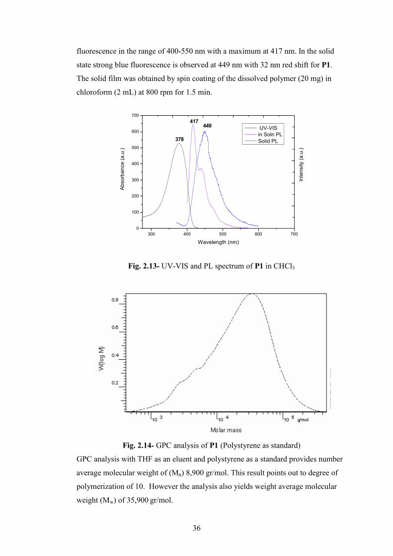
36
fluorescence in the range of 400-550 nm with a maximum at 417 nm. In the solid
state strong blue fluorescence is observed at 449 nm with 32 nm red shift for P1.
The solid film was obtained by spin coating of the dissolved polymer (20 mg) in
chloroform (2 mL) at 800 rpm for 1.5 min.
300 400 500 600 700
0
100
200
300
400
500
600
700
Intensity (a.u.)
Absorbance (a.u.)
Wavelength (nm)
UV-VIS
in Soln PL
Solid PL378
417449
Fig. 2.13- UV-VIS and PL spectrum of P1 in CHCl3
Fig. 2.14- GPC analysis of P1 (Polystyrene as standard)
GPC analysis with THF as an eluent and polystyrene as a standard provides number
average molecular weight of (Mn) 8,900 gr/mol. This result points out to degree of
polymerization of 10. However the analysis also yields weight average molecular
weight (Mw) of 35,900 gr/mol.

37
3 0 0 0 2 0 0 0 1 0 0 0
0 ,0
0 , 2
0 , 4
0 , 6
Absorbance
W a v e n u m b e r ( c m- 1)
2 9 2 3
3 0 1 9 1 6 0 0
1 5 5 8
7 2 7
Fig. 2.15- The FT-IR spectrum of P1
In FT-IR spectrum of P1, aromatic carbon hydrogen bond stretching at 3019 cm-1
and aliphatic carbon hydrogen bond stretching at 2923 cm-1 are observed. The
aromatic carbon double bonds appear at 1600 cm-1 and 1558 cm-1.
2.1.6 Synthesis and Characterization of poly[(9,9-Dihexyl-9H-fluorene)-co-alt-
(9,9-bis-(6-azido-hexyl)-9H-fluorene )] (P2)
As seen in Scheme 2.8, P1 was subjected to a nucleophilic substitution reaction with
NaN3 in DMF at 60 οC to prepare the poly[(9,9-Dihexyl-9H-fluorene)-co-alt-(9,9-
bis-(6-azido-hexyl)-9H-fluorene )] P2. It was purified by precipitation into methanol
three times. The product was obtained as a yellow fine powder.
BrBr
*
NaN3, DMF
60 oC, 24 h, % 75
N3N3
*
Scheme 2.8- The synthesis of P2

38
Fig. 2.16- 1H-NMR spectrum of P2 (400 MHz, CDCl3, 25 οC)
The characterization of P2 was carried out by 1H NMR, UV-VIS, Fluorescence and
FT-IR spectroscopy. The 1H NMR spectrum shows 12 aromatic protons at 7.75 ppm
as a multiplet. The hexyl protons are seen between 3.16 ppm and 0.82 ppm The
characteristic f protons next to the electronegative nitrogen atom are observed at
3.16 ppm.. The methylene protons next to nitrogen atoms are less deshielded
compared to precursor P1.
Fig. 2.17- GPC analysis of P2 (Polystyrene as standard)
GPC analysis was done using THF as an eluent and polystyrene as a standard
providing number average molecular weight of (Mn) 3,680 gr/mol. The degree of
polymerization was found to be around 5. The weight average molecular weight
(Mw) was determined as 14,700 gr/mol.

39
3 5 0 0 3 0 0 0 2 5 0 0 2 0 0 0 1 5 0 0 1 0 0 0
0 ,1
0 ,2
0 ,3
0 ,4
0 ,5
0 ,6
0 ,7
0 ,8
0 ,9
1 ,0
Absorbance
W a v e n u m b e r ( c m- 1)
C -N3, 2 0 9 5
2 9 2 9
3 0 2 61 6 0 5
Fig. 2.18- FT-IR spectrum of P2
In the FT-IR spectrum of P2 carbon azide stretching peak at 2095 cm -1 confirmed
the product formation. The aromatic carbon-hydrogen stretching at 3026 cm-1 and
aliphatic carbon-hydrogen stretching peak at 2929 cm-1 were present. The aromatic
carbon double bonds were observed at 1605 cm-1.
300 400 500 600 700
0
100
200
300
400
500
600
700
Intensity (a.u.)
Absorbance (a.u.)
Wavelength (nm)
UV-VIS
in Soln. PL
Solid PL
386417 448
Fig. 2.19- UV-VIS and PL spectrum of P2 in CHCl3
Absorption and emission spectra for P2 were recorded in chloroform at room
temperature. Figure 2.19 shows absorption band peaking at 386 nm due to the π-π*
transition with an absorption coefficient of 25,680. Optical excitation at 386 nm
gives a strong violet fluorescence in the range of 400-550 nm with a maximum at
417 nm. In the solid state strong blue fluorescence is observed at 448 nm with 31 nm

40
red shift for P2. The solid film wa obtained by spin coating of the dissolved polymer
(20 mg) in chloroform (2 mL) at 800 rpm for 1.5 min.
2.1.7 Towards functionalization of the P1 and P2
Formation of P1 and P2 was confirmed by spectroscopic techniques. Then we
attempted click chemistry reaction between P2 and propargylamine. Click chemistry
reaction is a useful reaction in formation of triazoles from coupling of azido and
alkyne monomers catalysed by Cu (II). The reaction can run in water through
reduction of Cu(II) to Cu(I). In our synthetic route P2 having a azide group was
reacted with propargylamine in THF/H20 solvent in rt as outlined in Scheme 2.9.
N3N3
* *
H2N THF/H2O, CuSO4.5H2O
Sodium Ascorbate
NN
*
N
N
H2N
N
N
NH2
*
2 d, % 45
P8
Scheme 2.9- The synthesis of P8
The product obtained was insoluble in both organic solvents and water. So its total
characterization was not possible. However, FT-IR spectrum showed the absence of
carbon-azide peak at 2092 cm-1. A band with a maximum at 3431 cm-1 was seen due
to amine groups. Also the aromatic and aliphatic carbon hydrogen bond stretchin
were seen at 3026 cm-1 and 2929 cm-1.

41
3 0 0 0 2 0 0 0 1 0 0 0
0 , 0 0
0 , 0 1
0 , 0 2
0 , 0 3
0 , 0 4
Absorbance
W a v e n u m b e r ( c m - 1)
2 9 2 9
3 4 3 1
2 0 9 2
1 6 1 2
3 0 2 6
Fig. 2.20- FT-IR spectrum of P8
FT-IR spectroscopy confirms the formation of the product. However, the obtained
product is insoluble in both organic and aqueous solvents. Insolubility of the product
can be explained by the formation of network like structure because of hydrophobic
interactions; hydrogen bonding interactions and π-π interactions between the triazole
rings.30
Insolubility of the product prevented us to continue threading the polymer with
triazole ring into CB(6). So, we tried next the azidoethylamine addition to poly[(9,9-
Dihexyl-9H-fluorene)-co-alt-(9,9-bis-(6-bromo-hexyl)-9H-fluorene )], P1. This
reaction’s product was important for 1,3 dipolar addition reaction catalyzed by
CB(6). Because CB(6) can form stable complexes with the amine groups.
BrBr
**n
NHHN
**n
H2N N3
N3 N3
P7
Scheme 2.10- The synthesis of P7
P7 was synthesized by the reaction of P1 with excess azidoethylamine in THF with
% 94 yield. The reaction is a nucleophilic substitution reaction in which bromine

42
atoms are substituted by amine groups. Excess azidoethylamine was used as a
solvent to prevent over alkylation. The reaction scheme of P7 is shown in Scheme
2.10 above.
P7 was investigated by FT-IR spectroscopy. In the FT-IR spectrum the carbon azide
stretching is seen at 2099 cm-1 confirming the addition reaction. At 3327 cm-1 the
amine stretching is observed. The carbon-hydrogen stretching for aromatic 3053 cm-
1 and for aliphatic at 2929 cm-1 are present.
3 5 0 0 3 0 0 0 2 5 0 0 2 0 0 0 1 5 0 0 1 0 0 0
0 , 2
0 , 4
0 , 6
0 , 8
1 , 0
1 , 2
1 , 4
1 , 6
1 , 8
2 , 0
Absorbance
W a v e n u m b e r ( c m- 1)
2 0 9 9
2 9 2 9
2 8 6 1
3 0 5 3
3 3 2 7
Fig. 2.21- FT-IR spectrum of P7
We attempted to treat P7 with acid to make it water soluble. To obtain water soluble
product was difficult. After extraction of the aqueous layer and evaporation of the
solvent very little amount of yellow solid was obtained. This product was
investigated by FT-IR spectroscopy. In Figure 2.22, FT-IR spectrum is shown. The
amine stretching band peaking at 3410 cm-1 is observed. The azide peak is present at
2113 cm-1.
3 5 0 0 3 0 0 0 2 5 0 0 2 0 0 0 1 5 0 0 1 0 0 0
0 , 1
0 , 2
0 , 3
0 , 4
0 , 5
0 , 6
Absorbance
W a v e n u m b e r ( c m- 1)
3 4 1 0
2 1 1 3
2 9 8 5
Fig. 2.22- FT-IR spectrum of P7 after acid treatment

43
The insolubility of the product in acidic medium prevented us to continue 1,3 dipolar
addition catalysed by CB(6). Because 1,3 dipolar addition reaction runs in acidic
medium.
2.1.8 Synthesis and Characterization of poly[9,9-bis-(6-bromo-hexyl)-9H-
fluorene-co-1,4-phenylene] (P3)
Insolubility of the polyfluorene copolymers did not allow us to continue to prepare
the desired pseudopolyrotaxane as discussed in the preceeding section. Then we
tried the preparation of fluorene-phenylene copolymers. Phenylene monomer is less
apolar because it contains no alkyl chains and less aromatic groups if compared to
former fluorene monomer with hexyl chains. We thought that in further steps
solubility in aqueous medium can be supplied with less apolar groups. 2,7-dibromo-
9,9-bis-(6-bromo-hexyl)-9H-fluorene was subjected to Suzuki coupling reaction
with 1-4, phenylene-diboronic acid using Pd(II) catalyst in THF/H2O as solvent. As
shown in Scheme 2.11 the reaction was carried out at 80 oC for three days to obtain
P3 in 94 % yield.
BrBr
* *n
BrBr
Br Br
B
BOHHO
OHHO
1
PdCl2 (dppf), K2CO3
THF/H20, 80 oC, 3 d
% 94
P3
Scheme 2.11- The synthesis of P3
1H NMR spectroscopy of P3 showed broad peaks at about 7.65 ppm for aromatic
protons. The signals between 3.32 ppm and 0.80 ppm are due to alkyl protons. The
signal at 3.32 ppm is for the methylene protons next to bromine atom.

44
Fig. 2.23- H-NMR spectrum for P3 (400 MHz, CDCl3, 25 οC)
300 400 500 600 700
0
100
200
300
400
500
600
700
Intensity ( a.u.)
Absorbance ( a.u.)
Wavelength (nm)
UV-VIS
in Soln. PL
Solid PL
366
410427
Fig. 2.24- UV-VIS and PL spectrum of P3 in THF
Figure 2.23 shows the absorption and emission spectra for P3. In THF solution P3
display an absorption band peaking at 366 nm. due to the π-π* transition with an
absorption coefficient of 28,450. P3 absorbs in lower wavelength than polyfluorene
copolymer as it has less double bonds. Optical excitation of P3 at 366 results a
strong violet emission at 410 nm. P3 shows strong blue fluorescence at 427 nm in
the solid state with a 17 nm red shift. The solid film was obtained by spin coating of
the dissolved polymer (20 mg) in THF (2 mL) at 800 rpm for 1.5 min.

45
Fig. 2.25- GPC analysis of P3 (Polystyrene as standard)
GPC analysis with THF as an eluent and polystyrene as a standard provides number
average molecular weight of (Mn) 1,370 gr/mol. This result points out to degree of
polymerization of around 3. However, the analysis provides a weight average
molecular weight (Mw) of 11,900 gr/mol.
Figure 2.24 shows the FT-IR spectrum of P3. In the FT-IR spectrum aromatic
carbon hydrogen at 3024 cm-1and aliphatic carbon hydrogen stretchings at 2929 cm-1
are present. The aromatic carbon double bonds are observed at 1606 cm-1.
3 0 0 0 2 0 0 0 1 0 0 0
0 , 0
0 , 1
0 , 2
0 , 3
0 , 4
0 , 5
Absorbance
W a v e n u m b e r
2 9 2 9
3 0 2 41 6 0 6
1 5 1 87 2 7
Fig. 2.26- FT-IR spectrum of P3

46
2.1.9 Synthesis and Characterization of poly[9,9-bis-(6-azido-hexyl)-9H-
fluorene-co-1,4-phenylene] (P4)
P3 was subjected to nucleophilic substitution reaction with sodium azide in aprotic
solvent, DMF, at 60 οC. The reaction time was two days as outlined in Scheme 2.12
below. Extraction and precipitation into methanol yielded the product in 62 % yield.
NaN3, DMF
BrBr
*
N3N3
* *n
60 oC, 2 d, % 62
*
n
Scheme 2.12- The synthesis of P4
The product was characterized by 1H-NMR,UV-VIS, Fluorescence and FT- IR
spectroscopy techniques. In Figure 2.27, 1H-NMR spectrum of P4 is seen. In the 1H-
NMR spectrum 10 aromatic protons are observed at 7.35 ppm. The other methylenic
protons are seen between 3.25 ppm and 0.75 ppm. The appearance of two triplets at
3.25 ppm and 3.32 ppm shows that bromine atoms are not substituted with the azide
groups completely.
Fig. 2.27- FT-IR spectrum of P4 (400 MHz, CDCl3, 25 οC)

47
The UV-VIS and Fluorescence spectra of poly[9,9-bis-(6-azido-hexyl)-9H-fluorene-
co-1,4-phenylene] show an absorption maximum at 366 nm with an absorption
coefficient of 21,650 and an emission maximum at 410 nm by excitation at 366 nm
in chloroform solution. In the solid state, P4 shows strong blue fluorescence at 427
and 446 nm with a red shift. The solid film were obtained by spin coating of the
dissolved polymer (20 mg) in CHCl3 (2 mL) at 800 rpm for 1.5 min.
300 400 500 600 700
0
200
400
600
Intensity (a.u.)
Absorbance (a.u.)
W ave leng th (nm )
UV-V IS
in So ln PL
So lid PL366
410
446
427
Fig. 2.28- UV-VIS and PL emission spectra of P4 in CHCl3
Fig. 2.29- GPC analysis of P4 (Polystyrene as standard)
GPC analysis of P4 was done with THF as an eluent and polystyrene as a standard
providing a number average molecular weight of (Mn) 2,410 gr/mol corresponding

48
to a degree of polymerization of 5. The weight average molecular weight (Mw) was
obtained 14,600 gr/mol.
In the FT-IR spectrum, carbon azide stretching peak at around 2093 cm-1, carbon
hydrogen stretchings for aromatic at 3026 cm-1and for aliphatic at 2925 cm-1 are
present. The aromatic carbon double bonds are observed at 1596 cm-1.
3 0 0 0 2 0 0 0 1 0 0 0
0 , 0
0 , 1
0 , 2
0 , 3
0 , 4
Absorbance
W a v e n u m b e r ( c m- 1)
- C -N3, 2 0 9 3
3 0 2 6
2 9 2 5
1 5 9 6
Fig. 2.30- FT-IR spectrum of P4
Formation of P3 and P4 was confirmed by spectroscopic techniques. P4, having a
azido group was tried to undergo click hemistry reaction as in Scheme 2.12. P9 was
synthesized by click chemistry reaction between P4 and propargylamine in
THF/H2O solvent mixture by the catalysis of Cu(II) at rt. After work-up brown
product was obtained in % 92 yield.
**
N3N3
**
NH2
CuSO4, THF/H2O
Sodium Ascorbate
NNN
H2N
N
N
N
H2N
1d, rt, % 92
P4
P9
Scheme 2.13- The synthesis of P9
The obtained was tried to dissolve in both organic and aqueous solvents. However,
the product was insoluble. So full characterization of the product was not possible.
The product was characterised only by FT-IR spectroscopy. Its FT-IR spectrum

49
showed the presence of amine group due to the band with a maximum at 3431 cm-1.
The aromatic and aliphatic carbon hydrogen bon stretchings were present at 3037
cm-1 and 2930 cm-1. The carbon azide peak at 2093 cm-1 disappeared.
3 5 0 0 3 0 0 0 2 5 0 0 2 0 0 0 1 5 0 0 1 0 0 0
0 , 3 0
0 , 3 5
0 , 4 0
0 , 4 5
0 , 5 0
0 , 5 5
0 , 6 0
Absorbance
W a v e n u m b e r ( c m- 1)
3 4 3 1
2 9 3 0
1 6 0 2
3 0 3 7
Fig. 2.31- FT-IR spectrum of P9
Insolubility can be explained by formation of network like structure because of
hydrophobic interactions; hydrogen bonding interactions and π-π interactions from
the triazole rings as explained above.30 Insolubility of the product disabled us to
attach CB(6) for the preparation of polypseurotaxane.
2.1.10 Synthesis and Characterization of poly[9,9-bis-(6-bromo-hexyl)-9H-fluorene-
co-2,5-thienylene] (P5)
We tried to synthesize pseudopolyrotaxane with a different band-gap copolymer. We
tried to synthesize fluorene-thienylene copolymer as shown in Scheme 2.12 below.
Poly[9,9-bis-(6-bromo-hexyl)-9H-fluorene-co-2,5-thienylene] P5 was synthesized
by Suzuki coupling reaction of 2,7-dibromo-9,9-bis-(6-bromo-hexyl)-9H-fluorene
with thiophene-2,5-diboronic acid using Pd(II) catalyst with phase transfer catalyst,
tetrabutlyammoniumbromide in THF/H2O solvent. We added phase transfer catalyst
to increase the yield. Extraction and precipitation into methanol yielded 62 % of
poly[9,9-bis-(6-bromo-hexyl)-9H-fluorene-co-2,5-thienylene].
50
BrBr
Br Br
S B(OH)2(HO)2B
*
Br Br
S*
n
PdCl2(dppf), K2CO3
TBAB, THF/H2O,
60oC, % 62
Scheme 2.14- The synthesis of P5
The product was investigated by FT-IR, UV-VIS, Fluorescence and 1H-NMR
spectroscopy. In Figure 2.32, 1H-NMR is shown. 1H-NMR spectrum shows broad
multiplet at 7.35 ppm for aromatic fluorene protons and thienylene protons. The
alkyl protons are observed between 3.20 ppm and 0.60 ppm. The signal at 3.20 ppm
is due to methylene protons close to bromine atom.
Fig. 2.32- 1H-NMR spectrum of P5 (400 MHz, CDCl3, 25 οC)
UV-VIS and Fluorescence spectra of P5 shows an absorption band with a maximum
at 400nm with an absorption coefficient of 12,675 and an emission maximum at 464
nm in chloroform solution. At the solid state copolymer shows strong green
fluorescence at 506 nm with a 42 nm red shift. The solid film were obtained by spin
coating of the dissolved polymer (20 mg) in CHCl3 (2 mL) at 800 rpm for 1.5 min.

51
300 350 400 450 500 550 600 650 700
0
50
100
150
200
250
300
350
Intensity (a.u.)
Absorbance (a.u.)
Wavelength (nm)
Solid PL
UV-VIS
in Soln PL
400464
506
Fig. 2.33- UV-VIS and PL emission spectra of P5 in CHCl3
GPC analysis of P5 with THF as an eluent and polystyrene as a standard showed a
number average molecular weight of (Mn) 698 gr/mol corresponding to a very low
degree of polymerization. The analysis showed a weight average molecular weight
(Mw) of 1,970 gr/mol
Fig. 2.34- GPC analysis of P5 (Polystyrene as standard)

52
In the FT-IR spectrum of P5 carbon-hydrogen stretchings for aromatic at 3034 cm-1
and aliphatic at 2926 cm-1 are present. The aromatic carbon double bonds are seen at
1604 and 1568 cm-1 as weak peaks.
3 0 0 0 2 0 0 0 1 0 0 0
0 , 0
0 , 1
0 , 2
0 , 3
0 , 4
0 , 5
Absorbance
W a v e le n g t h
3 0 6 4
2 9 2 51 4 5 4
1 6 0 4
1 5 6 8
Fig. 2.35- FT-IR spectrum of P5
We could not continue further modifications on P5 because of the time restriction.

53
2.1.11 Synthesis and Characterization of 9, 9-Bis-(6-azido-hexyl)-2,7-dibromo-9H-
fluorene (3)
The second method was forming rotaxane at the monomer level and then trying the
polymerization. We tried to functionalize fluorene monomer with a suitable azido or
alkyne monomer. Then, by addition of azido monomer and CB(6), rotaxane would
be formed via CB(6)-catalysed 1,3 dipolar cycloaddition or by click creaction with
propargylamine by Cu(II) catalysis was attempted.
2,7-dibromo-9,9-bis-(6-bromo-hexyl)-9H-fluorene was subjected to a nucleophilic
substitution reaction with NaN3 in DMSO solvent at 70 οC. DMSO was chosen as an
aprotic solvent favoring the SN2 reaction. The reaction was carried out for one day
as shown in Scheme 2.13. Extraction yielded 9, 9-Bis-(6-azido-hexyl)-2,7-dibromo-
9H-fluorene in a % 82 yield as a yellow oil.
Br Br
C6H12BrBrC6H12
Br Br
C6H12N3N3C6H12
NaN3
DMSO, 70 oC
% 82
Scheme 2.15- The Synthesis route of 3
The product was investigated through FT-IR spectroscopy. The presence of a strong
peak at 2091 cm -1 confirms the carbon azide stretching. Carbon hydrogen
stretchings for aromatic at 3042 cm-1 and for aliphatic at 2927 cm-1 are present.
Fig. 2.36- FT-IR spectrum of 3

54
Then, 3 was subjected to click chemistry reaction with propargylamine using Cu(II)
as a catalyst as outlined in Scheme 2.14
BrBr
N3 N3
BrBr
N NN
NN
N
NH2
CuSO4, THF/H2O
Sodium Ascorbate rt, % 60
H2N
NH2
Scheme 2.16- Click chemistry reaction between 3 and propargylamine
The reaction was done at rt to obtain brown gel in 60 % yield. The product was
insoluble in both organic and aqueous solvents. So its full characterization was not
possible. It was investigated by FT-IR spectroscopy. Its FT-IR spectrum showed the
presence of amine group due to a band with a maximum at 3410 cm-1. The strong
carbon azide bond stretching has disappeared. Also aliphatic carbon hydrogen
stretching was seen at 2936 cm-1.
3 5 0 0 3 0 0 0 2 5 0 0 2 0 0 0 1 5 0 0 1 0 0 0
0 , 0
0 , 1
0 , 2
0 , 3
0 , 4
0 , 5
Absorbance
W a v e n u m b e r ( c m- 1)
3 4 1 02 9 3 6
2 1 1 3
1 6 5 6
Figure 2.37- FT-IR spectrum of click chemistry reaction product

55
2.1.12 Synthesis of {6-[2,7-Dibromo-9-(6-prop-2-ynylamino-hexyl)-9H-fluoren-9-yl]-
hexyl}-prop-2-ynyl-amine 4
BrBrNHHN
Br
H2N
BrBrBr
4
CHCl3 , rt, % 90
Scheme 2.17- The Synthesis of 4
{6-[2,7-Dibromo-9-(6-prop-2-ynylamino-hexyl)-9H-fluoren-9-yl]-hexyl}-prop-2-
ynyl-amine 4 was synthesized by the reaction of 2,7-dibromo-9,9-bis-(6-bromo-
hexyl)-9H-fluorene with excess propargylamine in chloroform in % 90 yield. The
reaction was a nucleophilic substitution reaction in which bromine atoms are
substituted by propargylic amine groups. Excess propargylamine was used as a
solvent to prevent over alkylation. The reaction scheme of 4 is shown in Scheme
2.17 above.
The product was investigated by FT-IR spectroscopy. The terminal alkyne is seen as
a strong peak at 3300 cm-1.The amine stretching at 3362 cm-1 is present. The
aliphatic carbon-hydrogen stretching is observed at 2936 cm-1
3 5 0 0 3 0 0 0 2 5 0 0 2 0 0 0 1 5 0 0 1 0 0 0
0 ,0
0 ,2
Absorbance
W a v e n u m b e r ( c m- 1)
3 3 0 0
2 1 0 7
2 9 3 6
3 3 8 2

56
Fig. 2.38- FT-IR spectrum of 4
After treatment with dilute NaOH and extraction the product was tried to be
acidified to make it water soluble. However, the product was insoluble in water. The
insolubility can be explained by the formation of the crosslinking between the
terminal alkyne groups. So, strong crosslinking between the chains might have
formed an impenetrable molecule. The insolubility prevented us to continue 1,3
dipolar addition with an azido monomer catalysed by CB(6).
2.1.13 Formation of Rotaxane
NH
NH
N3
N3
H3NCl
CB(6)
NH
NH
NNN
H3N
NNN
NH3Br
Br
Br
Br3 d, rt, % 20
Scheme 2.18- The synthesis of rotaxane
Monomer functionalized with azidoethylamine was subjected to 1,3-dipolar
cycloaddition catalysed by cucurbit[6]uril with propargylammonium salt. The
reaction was carried out at water as a solvent. Precipitation into acteone yielded the
rotaxane in % 20 yield. The product was characterized by FT-IR and 1H-NMR
spectroscopy.
In Figure 2.39 FT-IR spectrum shows the carbonyl stretching at 1730 cm-1 due to
CB(6). Amine stretching is seen as a band with a maximum at 3431 cm-1. Aliphatic
carbon-hydrogen sretching at 2929 cm-1 is present.

57
3 5 0 0 3 0 0 0 2 5 0 0 2 0 0 0 1 5 0 0 1 0 0 0
0 , 0
0 , 2
0 , 4
Absorbance
W a v e n u m b e r ( c m- 1)
3 4 3 1
1 7 3 0
2 9 2 9
Fig. 2.39- FT-IR spectrum of rotaxane
The 1H-NMR shows the presence of shielded triazole proton at 6.5 ppm. The
aromatic protons are observed as a multiplet between 7.8 ppm and 7.5 ppm. The
spectrum also shows alkyl protons between 4.0 ppm and 0.6 ppm.
Fig. 2.40- 1H-NMR spectrum of Rotaxane. (400 MHz, D2O, 25 οC)
We could not prepare pseudopolyrotaxane by Suzuki coupling reaction between the
rotaxane and the corresponding monomer boronic ester because of the time
restriction.
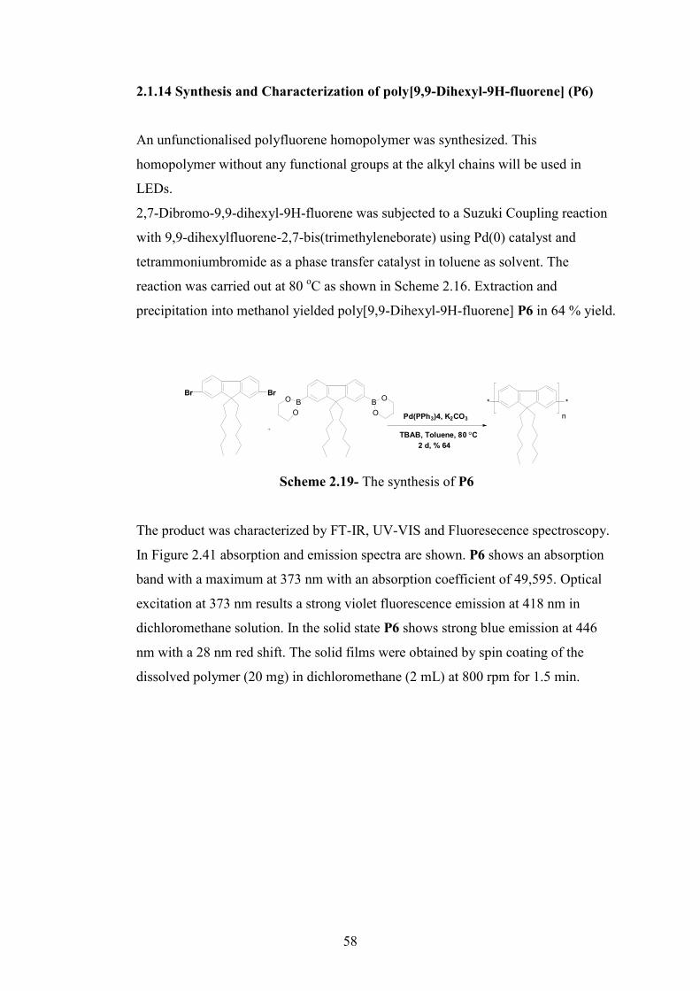
58
2.1.14 Synthesis and Characterization of poly[9,9-Dihexyl-9H-fluorene] (P6)
An unfunctionalised polyfluorene homopolymer was synthesized. This
homopolymer without any functional groups at the alkyl chains will be used in
LEDs.
2,7-Dibromo-9,9-dihexyl-9H-fluorene was subjected to a Suzuki Coupling reaction
with 9,9-dihexylfluorene-2,7-bis(trimethyleneborate) using Pd(0) catalyst and
tetrammoniumbromide as a phase transfer catalyst in toluene as solvent. The
reaction was carried out at 80 οC as shown in Scheme 2.16. Extraction and
precipitation into methanol yielded poly[9,9-Dihexyl-9H-fluorene] P6 in 64 % yield.
BrBr
Pd(PPh3)4, K2CO3
TBAB, Toluene, 80 oC
2 d, % 64
BBO
O
O
O
*
n
*
Scheme 2.19- The synthesis of P6
The product was characterized by FT-IR, UV-VIS and Fluoresecence spectroscopy.
In Figure 2.41 absorption and emission spectra are shown. P6 shows an absorption
band with a maximum at 373 nm with an absorption coefficient of 49,595. Optical
excitation at 373 nm results a strong violet fluorescence emission at 418 nm in
dichloromethane solution. In the solid state P6 shows strong blue emission at 446
nm with a 28 nm red shift. The solid films were obtained by spin coating of the
dissolved polymer (20 mg) in dichloromethane (2 mL) at 800 rpm for 1.5 min.

59
300 400 500 600 700
0
200
400
600
Intensity (a.u.)
Absorbance (a.u.)
Wavelength (nm)
UV-VIS
in Soln. PL
Solid PL
373 418
446
Fig. 2.41- UV-VIS and PL emission spectra of P6 in Dichloromethane
The FT-IR spectrum shows carbon-hydrogen bond stretchings for aromatic at 3031
cm-1and for aliphatic at 2929 cm-1. The aromatic carbon double bonds are observed
at 1606 cm-1.
3 5 0 0 3 0 0 0 2 5 0 0 2 0 0 0 1 5 0 0 1 0 0 0
0 , 2
0 , 4
0 , 6
0 , 8
1 , 0
1 , 2
1 , 4
Absorbance
W a v e n u m b e r ( c m- 1)
2 9 2 9
3 0 3 11 6 0 6
Fig. 2.42- FT-IR spectrum of P6
60
2.2 White light generation by a hybrid polymer-inorganic device55
In this section we introduce our results for white light generation exploiting a recent
approach; a small polymer excited with near UV light sourced by GaN. GaN acts as
a near UV LED to excite our polymer, and the only layer of the polymer emits white
light. This hybrid organic/inorganic LED approach was frstly introduced by Hide et.
al.39 InGaN LED emitted blue UV light to pump the red emitting MEH-PPV and
green emitting BuEH-PPV polymers. There was reported a produced white light
with CIE coordinates of (0.34, 0.29). Almost at the same time Guha et. al. reported
hybrid inorganic/organic based LEDs using coumarin derivatives for production of
different emissive LEDs.40 Recently, Heliotis et. al. reported a hybrid LED pumped
by InGaN UV LED at 370 nm. and a blended mixture of blue-emitting poly-9,9-
dioctylfluorene-co-9,9-di-4-methoxy phenylfluorene, the green-emitting poly-9,9-
dioctyl fluorene-co-benzothiadiazole, and the Dow proprietary red emission
copolymer Dow Red F.41 The blend composition was adjusted between the blue and
the green and red emitters so that an incomplete energy transfer occurs to produce
white light with CIE coordinates of (0.30, 0.34).
Our WLED device relies on the use of a single, simple conjugated polymer namely
poly[(9,9-dihexylfluorene)-co-alt-(9,9-bis-(6-azidohexyl)fluorene)] P2 intentionally
cross-linked on top of the integrating near-ultraviolet (n-UV) LED platform. In this
approach, pumped by the near-UV InGaN/GaN LED at 378 nm, the P2 emitters that
are hybridized and cross-linked into the form of a thin film generates a down-
converting broad photoluminescence (PL) at longer wavelengths across the entire of
the visible spectrum, yielding a very high color rendering index above 90.
2.2.1 Device Fabrication
InGaN/GaN, based n-UV LED is epitaxially grown in a GaN dedicated metal
organic chemical vapor deposition (MOCVD) reactor at Bilkent University
Nanotechnology Research Center (NANOTAM). After the growth of a 25 nm thick
nucleation layer, a 200 nm thick GaN buffer layer is deposited, which is followed by
the Si doped, GaN n layer. Subsequently, 5 quantum wells and barriers with
thickness of approximately 2-3 nm, respectively, are grown as the active region to
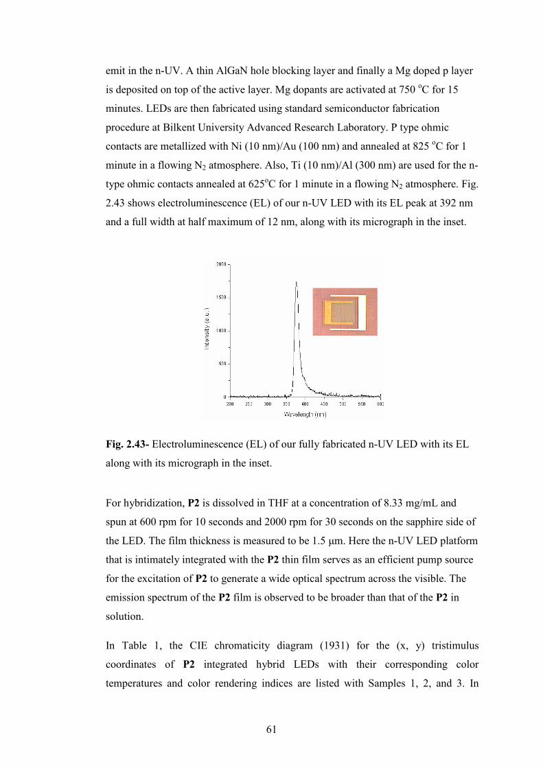
61
emit in the n-UV. A thin AlGaN hole blocking layer and finally a Mg doped p layer
is deposited on top of the active layer. Mg dopants are activated at 750 oC for 15
minutes. LEDs are then fabricated using standard semiconductor fabrication
procedure at Bilkent University Advanced Research Laboratory. P type ohmic
contacts are metallized with Ni (10 nm)/Au (100 nm) and annealed at 825 oC for 1
minute in a flowing N2 atmosphere. Also, Ti (10 nm)/Al (300 nm) are used for the n-
type ohmic contacts annealed at 625oC for 1 minute in a flowing N2 atmosphere. Fig.
2.43 shows electroluminescence (EL) of our n-UV LED with its EL peak at 392 nm
and a full width at half maximum of 12 nm, along with its micrograph in the inset.
Fig. 2.43- Electroluminescence (EL) of our fully fabricated n-UV LED with its EL
along with its micrograph in the inset.
For hybridization, P2 is dissolved in THF at a concentration of 8.33 mg/mL and
spun at 600 rpm for 10 seconds and 2000 rpm for 30 seconds on the sapphire side of
the LED. The film thickness is measured to be 1.5 µm. Here the n-UV LED platform
that is intimately integrated with the P2 thin film serves as an efficient pump source
for the excitation of P2 to generate a wide optical spectrum across the visible. The
emission spectrum of the P2 film is observed to be broader than that of the P2 in
solution.
In Table 1, the CIE chromaticity diagram (1931) for the (x, y) tristimulus
coordinates of P2 integrated hybrid LEDs with their corresponding color
temperatures and color rendering indices are listed with Samples 1, 2, and 3. In

62
addition, Sample 4 demonstrates the coordinates of P1 as the control group. The
three filled circles on the CIE diagram in Fig. 2.44 schematically represent the pairs
of (x, y) chromaticity coordinates of the P2-hybridized device listed in Table 1.
X Y Tc
(K)
CRI
1 0.2434 0.2723 19634 86
2 0.2913 0.2770 9416 87
3 0.2554 0.2426 32371 91
4 0.1932 0.1408 34367 64
Table 1- Chromaticity coordinates, color temperature, and color rendering index
results
Fig. 2.44- P2 hybridized on n-UV LED in the white region on CIE chromaticity
diagram (inset: a photograph of its white light emission).55

63
We intentionally used polyfluorene whose side chains can be substituted with a
group facilitating the cross-linking. For example, bromide groups can be converted
to azide groups to allow thermal or photochemical crosslinking.44 Thus, it is known
that by heating or UV-irradiation the azide group (-N3) decomposes to a highly
reactive nitrene (-N:) with the loss of nitrogen and the resulting nitrene can
subsequently insert into side chains or the polymer backbone leading to the
formation of crosslinks. This, in turn, causes a change in the polymer chain
conformations and in optical properties of the polymer.
While the spectral broadening that stems from cross-linking is not desired in
polymers for display applications, which are preferably aimed to be operated at
specific wavelengths, this is an advantageous feature for white light generation
applications. The ability of azide functionalized polyfluorene (P2) to feature the
broadest spectrum across the visible is caused by uncontrollable cross-linkable
reacting species, which damage or eventually lengthen the conjugation chain by
random ruptures and linkages of bonds. The randomness of the cross-link
mechanism of P2 is specifically verified after an investigation of two independent
film of P2 after heat exposure. Next, the heat exposure on the polymers will be
discussed methodologically.
2.2.2 Thermal Stability and Degradation Behaviour of the Polymers
Firstly, decomposition of the carbon azide bond and formation of the fluorenone
species in azide functionalized copolymer were investigated via in-situ FT-IR
spectroscopy. The azide functionalized copolymer was heated gradually from rt. to
237 οC. Temperatures at rt, 50 οC, 80 οC, 100 οC, 120 οC, 150 οC, 170 οC, 195 οC,
220 οC, 230 οC, 233 οC, 237 οC were recorded as shown in Figure 2.45. The
investigation was dependent upon the disappearance of the –C-N3 peak at 2094 cm -1
and the formation of carbonyl peak at 1720 cm -1 coming from fluorenone species.
At 195 οC the carbon azide peak began to decrease while no substantial occurrence
of fluorenone species was observed. It seemed that some azide groups are
decomposed to reactive nitrene species. This enhanced the crosslinking of the
polymer began earlier than keto formation. At 220 οC the formation of the
fluorenone species were observed because of the peak at1720 cm-1. Above 220 οC

64
the carbon azide peak disappeared completely, and the carbonyl peak became
evident in an additional 17 οC.
3500 3000 2500 2000 1500 1000
-0,05
0,00
0,05
0,10
0,15
0,20
0,25
0,30
0,35
0,40
0,45
0,50
0,55Absorbance
Wavenumber (cm-1)
RT
50 C
80 C
100 C
120 C
150 C
170 C
195 C
220 C
230 C
233 C
237 C
2000
0,0
0,2
0,4
Absorbance
W avenumber (cm-1)
RT
50 C
80 C
100 C
120 C
150 C
170 C
195 C
220 C
230 C
233 C
237 C
Fig. 2.45- (a)In-situ FT-IR measurement of P2 under heat exposure, (b)Inset
between 2300 cm -1 and 1500 cm -1
The crosslinking and degradation beaviour of P2 were also investigated by in-situ
Fluorescence spectroscopy. The azide functionalized copolymer was heated
gradually from rt. to 235 οC. Temperatures at rt., 50 οC, 100 οC, 150 οC, 200 οC, 235

65
οC were recorded as shown in Figure 2.46. Furthermore, to investigate whether the
changes in the polymer reversible or not the polymer was cooled down to rt from the
heated temperature. When heated above rt., we observed a decrease in the the
intensity of the PL without forming a new band or changing the emission spectrum
band. However, after cooling the polymer to rt. the polymer relieved the intensity
decrease but never achieved the former intensity. Heating above 150 οC a new band
occured at about 540 nm spanning the green region. Hence it seemed that, in this
occasion, crosslinking causes the formation of the green emission band. And further
heating caused the increase of this band while the keto sites increase as shown by
FT-IR spectrum above.
400 450 500 550 600
0
10
20
30
40
50
60
70
80
Intensity
Wavelength (nm)
RT
50 oC
50 oC RT
100 oC
100 oC RT
150 oC
150 oC RT
200 oC
200 oC RT
235 oC
Fig. 2.46- In-situ PL measurement of P2 under heat exposure
In-situ UV-VIS spectroscopy was also used for investigation of the thermal stability
of P2. Absorption behaviour during heat exposure was investigated. Absorptions at
rt, 50 οC, 100 οC, 150 οC, 200 οC and 235 οC were recorded as shown in Figure 2.47.
The azide functionalized copolymer absorbs at about 385 nm because of the π-π*
transition in the solid state at room temperature. In general picture, during gradual
heat exposure the polymer kept its band shape. We only observed a brief shift in
λmax value. We expected no lowering in the absorption spectra as in the emission
spectra because the absorbing species stayed always the same, the polyfluorene

66
backbone. The absorbing species in the molecule did not change but the pathways
they relaxed changed.
300 400 500 600
0,05
0,10
0,15
0,20
0,25
0,30
0,35
0,40
0,45
Absorbance
Wavelength
RT
50 oC
100 oC
150 oC
200 oC
235 oC
Fig. 2.47- In-situ UV-VIS measurement of P2 under heat exposure
To compare the thermal stability behaviour of P2 and to investigate what azide
functionalisation adds to P2, thermal stability experiments were done for bromo-
fuctionalised copolymer (P1) and the unfunctionalised homopolmer (P6) via in situ
Fluorescence Spectroscopy. In Figure 2.48 the emission spectra of the bromide
functionalized copolymer is shown for rt, 50 οC, 100 οC, 150 οC, 200 οC and 235 οC.
Also rt emission was recorded after cooling to rt from the heated temperature. At the
first sight, increasing temperature decreased the intensity of the emission and
subsequent cooling to rt relieved this decrease but the emission never reached to the
former rt emission. Also, it was observed that band shape did not change until 200 οC. The green emission band was observable at 200 οC. However, in the azide
fuctionalised copolymer the new band appeared at 150 οC. From this, we can
comment that crosslinking of the P2 began earlier than the formation of keto defects.

67
400 450 500 550 600
0
10
20
30
40
50
60
Intensity
Wavelength (nm)
RT
50 oC
50 oC RT
100 oC
100 oC RT
150 oC
150 oC RT
200 oC
200 oC RT
235 oC
Fig. 2.48- In-situ PL measurement of P1 under heat exposure
The above analysis conditions are applied to homopolymer (P6) to investigate
thermal stability and degradation behaviour. In Figure 2.49 the emission spectra of
the unfunctionalised homopolymer is illustrated for rt, 50 οC, 100 οC, 150 οC, 200 οC, 235 οC. Also rt emission was recorded for after each cooling from the heated
temperature. The homopolymer showed the same trend as bromo- functionalised
polymer P1. Subsequent cooling to rt relieved the decrease of the intensity at higher
temperatures but the emission never reached the former rt emission. The appearance
of the green emission band was observed at 200 οC. This result supported that the
formation of crosslinking began earlier than formation of keto defects in P2.

68
400 450 500 550 600 650 700
0
10
20
30
40
50
60
70
80
Intensity
Wavelength
RT
50
50RT
100
100RT
150
150RT
200
200RT
235
Fig. 2.49- In-situ PL measurement of P6 under heat exposure

69
2.3 Synthesis and characterization of cucubit[6]uril encapsulated polypyrrole
pseudopolyrotaxane56
Polypyrrole (PPy) was first introduced by D.E. Weiss et al.46 They were able to
synthesize polypyrrole from pyrolysis of tetraiodopyrrole. Since then polypyrrole
was widely studied because it has metallic electrical conductivity, environmental
stability and relative easy synthesis.47 These advantages led to the utilisation of the
material in various applications in electrochromic devices, sensors and electronic
devices etc.47 For example, a rechargeable battery prepared by Palmore et al.
recently.48 However, a soluble polypyrrole was not able to be synthesized because of
strong intra and inter-chain interactions except adding some surfactants and
counterions.49 This latter approach creates a drawback for processability of the
polymer.
Rotaxanation was suggested to separate the polymer chains. Thus, solubility can be
enhanced by breaking intra and inter-chain interactions. Encapsulation of the
polypyrrole main chain into macrocycles can help in controlling chain packing.
Achieving encapsulation of PPy into macrocyles have not been reported thoroughly
yet. Pyrrole monomers were successfully complexed with cyclodextrin units.26
However, the polymer unthreads from the macrocycle in the course of oxidation.
Our objective was to explore methods of synthesising CB(6)-encapsulated
polypyrrole. Our synthetic strategy involved first the preparation of an inclusion
complex between CB6 and pyrrole (Py) in NaCl solution and the subsequent
polymerisation of this complex with an oxidising agent to form pseudopolyrotaxanes.
Polypyrrole formation failed using FeCl3 as an oxidising agent in a NaCl solution,
but replacing NaCl solution by an acid solution produced polypyrrole. Spectroscopic
methods including FT-IR, UV-VIS and fluorescence clearly indicated the formation
of CB6-encapsulated polypyrrole. This is one of the first reported examples of the
photoluminescence (PL) of non substituted polypyrrole and the synthesis of CB-
encapsulated conjugated polymers.
In order to prepare poly-pyrrole-pseudorotaxane, we first prepared an inclusion
complex between CB6 and pyrrole in 0.1M NaCl solution as outlined in Scheme

70
2.20. We used a NaCl solution, because CB6 dissolves in an aqueous solution of
alkaline metal salts. One equivalent of CB6 was dissolved in 0.1M NaCl solution
and one equivalent of pyrrole was added at rt. The addition produced a clear solution
which became cloudy and viscous after about 15 min. This mixture was stirred
overnight at rt and in air. White precipitates were collected by centrifugation and
dried under vacuum overnight.
The mechanism of the CB6-Py inclusion complex formation is similar to complex
formation between CB6 and THF in NaCl solution.50 However, pyrrole has a more
rigid structure than THF and consequently, when it enters the cavity of CB6, it
probably pushes away the Na+ ions and thus, pseudorotaxane precipitates out.
Na Na
NH0.1 M NaCl
CB6
N N
N N
O
O
*
*
*
*6
cucurbit(6)uril
NaNH
CB6-Py inclusioncomplex
Scheme 2.20- Synthesis of the inclusion complex between CB6 and pyrrole in 0.1M
NaCl solution.
When this inclusion complex was left in air for weeks, no colour change caused by
oxidation of pyrrole was observed. It seems that, by encapsulation pyrrole becomes
chemically more stable. Pseudorotaxane is sparingly soluble in water and completely
soluble in acidic water, but it is insoluble in any organic solvents. The solubility of
pseudorotaxane in D2O is insufficient to obtain a 1H-NMR spectrum but it is
relatively more soluble in a NaCl solution, so that the 1H-NMR spectrum was
recorded in this solution. In Figure 2.50, the 1H-NMR spectrum shows four sets of
distinct chemical shifts which correlate well with the proposed structure in Scheme
2.3.1. There are two well-resolved triplets with coupling constants of about 2 Hz at
5.92 and 5.25 ppm due to protons labelled as c and b; there are also two broad peaks
at 6.79 and 6.13 due to protons d and a respectively (Scheme 2.21, labelled
structure). Chemical shifts due to CB6 protons appear to split further, confirming the
asymmetrical nature of the inclusion complex.

71
Fig. 2.50 - 1H-NMR spectrum (400 MHz, 0.2 M NaCl in D2O, 25 οC) of CB6-
pyrrole inclusion complex.
After characterizing the inclusion complex by 1H-NMR, we set out to investigate the
formation of polypyrrole-pseudorotaxane. Various methods were tried. In the first,
one equivalent of CB6-Py complex was dissolved in 0.2M NaCl solution and
subsequenty one equivalent of aqueous FeCl3 solution was added. The solution
became yellow and remained yellow through 24 h of stirring at rt. No colour change
associated with the reduction of iron to form polypyrrole was seen. The UV-VIS
spectrum of this solution was recorded but there was no band from polypyrrole
formation around the visible region. The reaction mixture was heated at 60 °C
overnight and the UV-VIS spectrum was recorded, however, the spectrum was
similar to the previous one. We therefore, concluded that FeCl3 could not oxidize
pyrrole to polypyrrole because it probably coordinates with carbonyl of the CBs
portals and could not reach the pyrrole. Another possibility is that the sodium ions
act as a gate-keeper preventing the FeCl3 from getting close to the pyrrole molecules.
i) 6M HCl,
ii) FeCl3
rt, 24 h, 72%NH
HN
NH
*
n
NaNH
d
c
a
b
a
b
c d
Scheme 2.51- The synthesis of CB6-encapsulated polypyrrole.

72
To eliminate the effect of sodium ions on polymerisation, we decided to dissolve the
complex in HCl solution instead of NaCl solution. Accordingly the complex was
dissolved in 6M HCl solution; a yellowish clear solution was obtained. We divided
this solution in two parts. The aqueous solution of FeCl3 was added to one part
leaving the other part of the mixture FeCl3-free; both reactions were stirred at rt
following the progress of the reactions by UV-VIS spectroscopy (Scheme 2.21).
Within a few hours, in UV-VIS spectra of both reaction mixtures, a broad band in
the region of 450-480 nm appeared and over time it became sharper and shifted to
485 nm; its intensity also increased. This result indicates that when CB6-Py
inclusion complex is dissolved in HCl solution, regardless of the presence of oxidant,
polypyrrole forms confirming that the polymerisation is mainly initiated by HCl.
Fig. 2.51- Ball-and-stick model of CB6-encapsulated polypyrrole and its 1H-NMR
spectrum (400 MHz, DMSO/D2O, 25 οC).
The solution was poured into a large excess of acetone and the salmon coloured
precipitate (Figure 2.55b) was collected by centrifugation and dried overnight in a
vacuum. Pseudopolyrotaxanes is slightly soluble in acidic water, in DMSO and in

73
DMF. However, at high concentrations an aggregate forms due to dissociation. We
were able to obtain a 1H-NMR spectrum of CB6-psudopolyrotaxanes in the mixture
of DMSO/D2O. The main interactions between CB and polypyrrole are hydrophobic
effect, hydrogen bonding between the –NH and carbonyl groups and the interaction
between carbonyl oxygen and the pyrrole rings protons. Because of these
interactions, probably the best ratio CB to pyrrole would be 1:3. Probably one
pyrrole unit is located inside the cavity and the other two are close to the carbonyl
portals (Figure 2.51, Ball-and-stick model of psudopolyrotaxanes). Accordingly, the
chemical shifts have assigned to protons as follows; the peaks at 4.7 and 5.5 ppm are
due to protons c and d respectively, which are encapsulated by CB6 as a result
shifted upfield; the peak at 6.1 ppm is due to protons a which are away from
carbonyl portal and the peak at 6.7 ppm belongs to protons b because they are close
to portal of the CB6, therefore shifted downfield.
3 5 0 0 3 0 0 0 2 5 0 0 2 0 0 0 1 5 0 0 1 0 0 00 ,0
0 ,2
0 ,4
0 ,6
0 ,8
1 ,0
1 ,2
1 ,4
1 ,6
1 ,8
2 ,0
Absorbnce
W a v e n u m b e r
1 7 3 8 , -C = O
3 4 2 6 , -N H
1 4 7 4 , -C = C -
1 3 6 9 , -C -N
( c m- 1)
Fig. 2.52- FT-IR spectrum of CB6-encapsulated polypyrrole.
The polymer was also analyzed by other spectroscopic techniques including FT-IR,
UV-VIS and fluorescence. FT-IR spectrum of psudopolyrotaxanes shows (Figure
2.52) N-H stretching at 3426 cm-1 which is characteristic for PPy. The peak due to
C=C stretching was seen at 1474 cm-1. The medium peak at 1369 cm-1 is attributed
to the C-N(str.) vibration. A strong peak at 1739 cm-1 due to C=O stretching
confirms the presence of CB6 in the polymer. The solid was stirred in 0.2 M NaCl
solution to determine whether CB6 encapsulated the polypyrrole or its presence is

74
due solely to H-bonding between the protons of polypyrrole and the carbonyl groups
of CB6. We assumed that If CB6 was not part of the polymer, it would form a
complex with Na ions and remain in solution and polypyrrole would precipitate out.
Thus, after treating the polymer with NaCl, we analyzed the solid and the
supernatant. The IR spectrum of the solid is similar to before washing--clearly
indicating the presence of CB6. The supernatant was evaporated and the IR
spectrum of the solid residue shows CB6 peaks. However, this could also indicate
the slippage of some CB6 rings from the polymer backbone during washing with salt
solution.
4 0 0 5 0 0 6 0 0 7 0 0
0 ,0 5
0 ,1 0
0 ,1 5
Absorbance
W ave le n g th (nm )
485
Fig. 2.53- UV-VIS spectrum of CB6-encapsulated polypyrrole in 6N HCl solution.
UV-VIS spectrum of psudopolyrotaxanes exhibits an absorption band at 485 nm due
to the π-π* transition which is characteristic for polypyrrole (Figure 2.53).51, 52
PL spectrum of psudopolyrotaxanes reveals an emission band at green region (521
nm) (Figure 2.54) when it is excited at 485 nm. This result was also supported by
comparing it with the photos taken of the solution of CB6-encapsulated polypyrrole
and the irradiation of this solution by UV-light. The acidic solution of PPy-CB6
psudopolyrotaxanes was light brown and showed a green emission under irradiation
with UV-light (Figure 2.55a).

75
3 0 0 3 5 0 4 0 0 4 5 0 5 0 0 5 5 0 6 0 0 6 5 0 7 0 0
Intensity (a.u.)
W a v e l e n g t h ( n m )
E x c i t a t i o n
E m i s s i o n
4 8 6 5 2 1
Fig. 2.54- PL spectra of CB6-encapsulated polypyrrole in 6M HCl solution.
On the basis of emission spectrum, we can assume that polypyrrole is threaded by
cucurbituril rings to form a pseudopolyrotaxanes. If polymer was not threaded by the
rings, there will be no emission due to strong interaction between the polymer chains.
a) (b)
Fig. 2.55- (a) The acidic solution of CB6-encapsulated polypyrrole is light brown
and exhibits a green PL under irradiation with UV-light; (b) Polypyrrole (black
powder) and CB6-encapsulated polypyrrole (salmon powder).
Figure 2.56 shows the powder XRD patterns of polypyrrole (c), CB6 (b), and
psudopolyrotaxanes (a). Polypyrrole was prepared using FeCl3 as an oxidising agent
under standard conditions (Figure 2.55b, black powder).49 The pattern of polypyrrole
illustrates that it is a typical non-crystalline amorphous polymer, however CB6,
when compared with spectrum 2.56c, has crystal composition because there are
three sharp peaks (2θ = 14.8, 23.2, 31.3) in the XRD pattern (Fig. 2.56b). Compared
with the parent polymer, the presence of CB6 provides some crystallinity and as a

76
result regularity to psudopolyrotaxanes as shown in the Figure 2.56a. Similar
changes have been observed in polyrotaxanes incorporating CB6 by Tan et al. 53
10 20 30 40
(b)
(c)
Intensity (a.u.)
2 Theta
(a)
0
Fig. 2.56- Powder XRD patterns of a) CB6-encapsulated polypyrrole, b) CB6, c) polypyrrole.

77
CHAPTER 3
CONCLUSION
In this thesis, a series of polyfluorene based copolymers have been synthesized via
Suzuki coupling for LED applictions.
Fluorene monomers functionalized with hexyl units have been synthesized.
Polyfluorene based polymers have been synthesized through coupling these
monomers with the corresponding boronic ester derivatives via Suzuki coupling
reaction. Copolymers consisted of repeating units of fluorene-fluorene, fluorene-
phenylene and fluorene-thiophene building blocks. Suzuki coupling was an
important tool to obtain high yield and soluble polymers.
Our aim was to modify conductive light emitting polymers through supramolecular
chemistry to obtain polymers with interesting and different properties than the parent
polymers. For example, it was possible to functionalise the C9 of blue light emitting
polyfluorene through rotaxanation using cucurbit[6]uril as a macrocycle. For this
purpose, we have tried two approaches. First approach involved the preparation of a
series of appropriate copolymers whose side chains allowed us to carry out
rotaxanation. Post modifications on the hexyl chains by attaching propargylamine or
formaton of a triazole ring yielded insoluble polymers through crosslinking of
alkyne groups with each other and triazole groups forming networks between each
other by strong H-bonding and π-π interactions. Insoluble post-modified polymers
disabled us to continue further.
In the second approach, first a fluorene monomer was functionalized with a suitable
azide monomer. Then, by addition of alkyne monomer and CB(6), rotaxane was
formed via CB(6)-catalysed 1,3 dipolar cycloaddition. The formation of rotaxane
was confirmed by the presence of a signal at 6.5 ppm in 1H-NMR spectrum. Further
polyrotaxane formation was not achieved due to time restriction. Functionalization

78
of the fluorene monomer with alkyne monomer yielded insoluble monomers because
of crosslinking between the alkyne groups.
In the next part, methods of preparing CB(6)-encapsulated polypyrrole were
investigated. It was found that pyrrole was threaded by CB(6) but since this complex
was not soluble in water, the polymerisation was tried in NaCl solution. However,
this solvent prevented Fe(III) to approach pyrrole as sodium ions coordinate with the
portal carbonyl of CB(6). As a result no polymerization was obtained. On the other
hand, dissolving the inclusion complex in 6M HCl solution, regardless of the
presence of FeCl3 as an oxidising agent, initiated polymer formation with moderate
yields. Spectroscopic analyses from FT-IR, UV-Vis, Fluorescence, 1H-NMR
confirmed the formation of CB(6)-encapsulated polypyrrole. Furthermore, by
encapsulation, separation of the polymer chains was possible and green fluorescence
emission was observed.
In the last part, WLED was prepared by a hybrid system by azide functionalized
polyfluorene copolymer and inorganic GaN species. Our WLED showed high CRI
indexes (>90). Azide groups, decomposed to nitrene groups formed crosslinks
allowing the broadening of the emission spectrum. Stability and degradation
behaviour of the polymer was studied under heat exposure. It was shown that
crosslinking began earlier than formation of fluorenone units.

79
CHAPTER 4
EXPERIMENTAL SECTION
All reagents and solvents were of the commercial reagent grade and used without
further purification except where noted. Pyrrole and aniline were distilled prior to
use. Column chromatography was carried out using silica gel (Kieselgel 60, 0.063–
0.200 mm). Thin layer chromatography (TLC) was performed on silica gel plates
(Kieselgel 60 F254, 1 mm). Nuclear magnetic resonance (NMR) spectra were
recorded on a Bruker Avance DPX–400 MHz spectrometer. UV measurements were
collected by Cary UV-VIS spectrophotometer. Fluoresence measurements were
taken by a Varian Cary Eclipse Fluorimeter. XRD pattern was recorded by Rigaku
MiniFlex X-Ray Diffaractometer. FT-IR Spectra were collected by Bruker FT-IR
spectrometer. GPC analyses were done by Agilent (HP) GPC apparatus. All
reactions were performed under argon.
4.1 Synthesis of 2,7-dibromo-9,9-bis-(6-bromo-hexyl)-9H-fluorene 1
2.7 Dibromofluorene (2.0 g, 6.17 mmol) and tetrabutylammoniumbromide (0.40 g,
1.20 mmol) were suspended in DMSO at rt. The mixture was flushed with nitrogen
gas for 30 min. As a result of addition of NaOH (10 mL, % 50) in one portion, a
viscous orange solution was observed. Following that 1,6 dibromohexane (9.5 mL,
60 mmol) was added. The reaction mixture was stirred at rt for 2 h. Work-up was
done by addition of tert-butyl methyl ether (250 mL) and water (100 mL) to the
reaction. The mixture was stirred for 15 min. The organic layer was extracted in tert-
butyl methyl ether and washed with water (100 mL), 2N HCl, brine and lastly again
with water. After drying over CaCl2 the solvent was evaporated under vacuum. The
crude product was purified with column chromatography packed with silica using
cylohexane as an eluent. The product was further purified by precipitating the
solution in CHCl3 into cold ethanol. Colorless crystals were obtained and dried
under vacuum.
Yield: 1.60 g (40%)
Mp: 66-70 οC

80
IR (KBr pellet, cm-1 ): 3025 (-CH, w), 2922 (-CH, s), 2859(-CH, s), 1598(C=C-, w),
1571(C=C-, w) 1H-NMR (400 MHZ, CDCl3) δH 7.35-7.2 (m, 6H), 3.34 ( t, 4H ), 1.95 (m, 4H), 1.7
(m, 4H), 1.20( m, 8H ), 0.65(m, 4H) 13C-NMR δC 23.6, 27.9, 29.1, 32.8, 33.9, 40.2, 55.9, 121.9, 122.3, 126.9, 131.1,
139.9, 153.1
Elemental Analysis: (C25H30Br4)
Calculated (%) C: 46.19; H: 4.65; Br: 49.16
Found (%) C: 46.69; H: 4.64
Rf: 0.63 (cyclohexane/chloroform 5:5)
4.2 Synthesis of 2,7-Dibromo-9,9-bis-(3-bromo-propyl)-9H-fluorene 2
2,7-Dibromofluorene (1.0 g, 3.08 mmol) and tetrabutylammoniumbromide ( 0.20 g,
0.60 mmol ) were suspended in DMSO (10 mL) at rt. The mixture was flushed with
nitrogen gas for 30 min. After addition of NaOH (5mL, %50) in one portion a
viscous orange solution was obtained. Following that 1,3-Dibromopropane (6.06 g,
30 mmol) was added. The reaction mixture was stirred at rt for two h. Work-up was
done by addition of tert-butyl methyl ether (250 mL) and water (100 mL) to the
reaction. The mixture was stirred for a 15 min. The organic layer was extracted in
tert-butyl methyl ether and washed with water (100 mL), 2N HCl, brine and lastly
again with water. After drying over CaCl2, the solvent was evaporated under
vacuum. The orange crude product was purified with column chromatography by
elution with a mixture of cyclohexane, chloroform (8/2, v/v) over silica. The product
was further purified by recrystallisation from cyclohexane to obtain white fine
powder.
Yield: (105 mg, %6)
Mp: 127-129 οC
IR (KBr pellet, cm-1) 3048 (CH-), 2927(CH-), 1605 (C=C-) 1H-NMR (400 MHZ, CDCl3) δH 7.45 (m, 6H), 3.05(t, 4H), 2.06(m, 4H), 1.08 (m,
4H) 13C-NMR δC 27.1, 33.7, 38.7, 54.8, 122.2, 122.7, 127.0, 131.7, 139.8, 151.6
Rf: 0.34 (cyclohexane/chloroform, 8/2, v/v)

81
4.3 Synthesis of 9, 9-Bis-(6-azido-hexyl)-2,7-dibromo-9H-fluorene 3
Sodium azide (0.10 g, 1.54 mmol) and 2,7-dibromo-9,9-bis-(6-bromo-hexyl)-9H-
fluorene (0.50 g, 0.77 mmol) were suspended in DMSO (10 mL) and the mixture
was heated to 60 οC for 24 h. A light yellow solution was obtained. The solution was
poured into water (40.0 mL) and organic layer was extracted with diethyl ether (50.0
mL X 3). The combined organic layers were washed with water after drying it over
CaCl2.The solvent was removed under reduced pressure to obtain a light yellow oil.
Yield: 360 mg (%82)
IR (NaCl plates, cm-1): 3042 (CH-, w), 2927 (CH-, s), 2091(C-N3, s )
Rf: 0.76 (Cyclohexane/Chloroform 1/1, v/v)
4.4 Synthesis of {6-[2,7-Dibromo-9-(6-prop-2-ynylamino-hexyl)-9H-fluoren-9-
yl]-hexyl}-prop-2-ynyl-amine 4
2,7-Dibromo-9,9-bis-(6-bromo-hexyl)-9H-fluorene (100 mg, 0.15 mmol) was
dissolved chloroform (4 mL) and added dropwise onto PGA (0.5 mL, excess). A
yellow solution was obtained. The reaction was stirred for one d. at rt. 0.1 M NaOH
(15 mL) was added and stirred for 2 hours and organic layer was extracted with
chloroform (20 mL). Solvent was evaporated and brown oil was tried to dissolve in
0.1 M HCl (25 mL). Organic layer was extracted with chloroform (25 mL) and the
solvent was evaporated under reduced pressure to obtain brown film
Yield: 83 mg (%90)
FT-IR (KBr pellet, cm-1): 3382 (-NH, w), 3300 (terminal alkyne, s), 2936 (-CH, s)

82
4.5 Synthesis of cucurbit[6]uril
Glycoluril (5.68 g, 40 mmol) was suspended in sulphuric acid ( 20 mL 9 M) and
heated to 75 οC to dissolve. Formaldehyde (7.0 mL from 37 % w/w aq. Sol., 100
mmol) was added into the clear reaction solution. The reaction was kept at 75 οC for
1 d and at 100 οC for 12 h. The reaction mixture was heated about 110 οC. The light
orange reaction solution was added into cold water (200mL). Diluted mixture was
precipitated into acetone (1L) to obtain white precipitates. The precipitates were
collected by suction and washed with water/acetone (200/800 mL). Obtained white
precipitates were added into water (200 mL) and stirred for 1 h. The precipitates
were filtered and added into hot formic acid (20 mL). Water (120 mL) was added
dropwise to obtain precipitates. After letting 1 d, white precipitates were observed.
The precipitates were collected and washed with hot water (100 mL). The whole
residues of solvents was evaporated under reduced pressure to obtain white fine
powder product.
Yield: 3 g (35 %)
Mp: >300 οC
FT-IR: (KBr pellet, cm-1): 3500 (NH-, m), 2999 (C-H, s), 1738 (C=O, s) 1H-NMR: (400 MHz, 0.2 M NaCl,D2O) = δH 4,46 (12H, d), 5,54 (12H, d), 5,75
(12H, s)
4.6 Addition of bis(pinacolato)diborane to 2,7-Dibromo-9,9-bis-(6-bromo-
hexyl)-9H-fluorene 5
Freshly distilled DMF (7 mL) was flushed under argon. Bispinacolatodiborane (430
mg, 1.69 mmol), KOAc (498 mg, 5.08 mmol) and PdCl2(dppf) (41 mg, 0.05 mmol)
and 2,7-dibromo-9,9-bis-(6-bromo-hexyl)-9H-fluorene (500 mg, 0.77 mmol) were
added. The red reaction mixture was flushed with argon for 15 min. Then, the
reaction mixture was refluxed at 80 οC for overnight. The gray-black reaction
mixture was added to cold water ( 50 mL) and organic layer was extracted with
chloroform ( 30 mL X 4). The solvent was removed under reduced pressure to
obtain light yellow crude product. The product was purified with coulumn
chromatography packed with silica, and cyclohexane/ethyl acetate (10:1, v/v) as

83
eluent. The product was obtained as white fine powder after recrystallisation from
cyclohexane.
Yield: 240 mg (% 42)
FT-IR (KBr pellet, cm-1): 3062 (-CH, w), 2929 (-CH, s), 1736 (-C=0, s), 1346 (B-0,
s) 1H-NMR (400 MHZ, CDCl3) δH 7.7-7.3 (m, 6H), 3.8 ( t, 4H ), 1.95 (m, 4H), 1.7 (m,
4H), 1.36 ( s, 24H ), 1.20( m, 8H ), 0.65(m, 4H)
4.7 Synthesis of Azidoethylamine42
2-chloroethylamine hydrochloride (5.0 g, 0.04 mmol) was dissolved in water (50
mL). Sodium azide (2.48 g, 38.0 mmol) was added slowly into the former solution.
The solution was refluxed at 70 οC for 2 d. Then, the reaction solution was cooled to
rt. Addition of NaOH solution ( 20 mL, 4.4 M ) followed by stirring for 2 h. Organic
layer was extracted with DCM (50 mL). After drying the organic layer over CaCl2 ,
solvent was evaporated under reduced pressure to obtain light yellow oil.
Yield: 2.50 g (%67)
FT-IR(NaCl plates, cm-1): 3369 (-NH), 2936 (-CH), 2102 (C-N3)
4.8 Synthesis of Rotaxane
Cucurbit[6]uril (435.0 mg, 0.435 mmol) was dissolved in 6N HCl (15 mL) and
stirred for 30 min. (2-Azido-ethyl)-(6-{9-[6-(2-azido-ethylamino)-hexyl]-2,7-
dibromo-9H-fluoren-9-yl}-hexyl)-amine (131 mg, 0.198 mmol) in 5 mL of 6N HCl
were added into former solution. Lastly propargylammonium salt ( 40 mg, 0. 435
mmol) was added. The reaction mixture was stirred for 3 d at rt. After evaporation of
the solvent under reduced pressure, an orange film was observed. It was dissolved in
minimum amount of water and precipitated into acetone (80 mL) for purification.
The precipitates were collected via centrifugation at 2500 rpm for 20 min. The
collected solids were dissolved in water and filtered by suction. The product was
purified by precipitation into acetone to obtain white fine powders.
Yield: 104 mg (% 20)
FT-IR (KBr pellet, cm-1): 3431 (-NH, b), 2929 (-CH, m), 1730 (-C=0, s)

84
1H-NMR (400 MHZ, D2O) selected δH 7.8-7.5 (m, 6H), 6.5 ( s, 2H ) 4.0-0.6 (alkyl
protons)
4.9 Synthesis of poly[(9,9-Dihexyl-9H-fluorene)-co-alt-(9,9-bis-(6-bromo-hexyl)-
9H-fluorene)] P1
2,7-Dibromo-9,9-bis-(6-bromo-hexyl)-9H-fluorene (975 mg, 0.150 mmol) and 9,9-
dihexylfluorene-2,7-bis(trimethyleneborate) (754 mg, 0.150 mmol) were suspended
in a mixture of degassed THF (15 ml) and H2O (7 ml). Pd(PPh3)4 (21 mg) and
K2CO3 (2.49 g, 18 mmol) were added sequentially. The mixture was degassed again
and heated at 80 °C for 48 h under argon and then poured into methanol. The
precipitate was collected by filtration and dissolved in chloroform. The solution was
washed with water and concentrated under reduced pressure. The concentrated
solution was poured into methanol; the solid residue was collected by centrifugation
and dissolved in THF. The solution was added into stirred large excess of MeOH.
The precipitate was collected by filtration and dried under vacuum to obtain
yellowish powder.
Yield: 1.1 g 64%.
IR (KBr pellet, cm-1):3019 (CH-, w), 2923 (CH-, s), 1600(C=C-, w), 1558(C=C-,
w), 727(C-Br, m), 1H-NMR (400 MHZ, CDCl3) δH 7.85 (m, 12H), 3.32 (t, 4H, J=6 Hz), 2.16 (m, 4H),
1.71 (m, 4H), 1.22(m, 24H), 0.84(m, 14H) 13C-NMR δc 140.5, 140.2, 139.9, 126.1, 121.1, 119.7, 54.7, 54.6, 39.6, 32.9, 31.8,
30.6, 28.8, 28.2, 26.9, 23.0, 21.6, 13.1
Mn:8.90*103 g/mol
Mw:3.59*104 g/mol
UV λmax : 384 nm (in Chlorofom)
PL λmax : 417 nm (in Chlorofom)

85
4.10 Synthesis of poly[(9,9-Dihexyl-9H-fluorene)-co-alt-(9,9-bis-(6-azido-hexyl)-
9H-fluorene )] P2
Poly[(9,9-Dihexyl-9H-fluorene)-co-alt-(9,9-bis-(6-bromo-hexyl)-9H-fluorene)] P1
(300 mg, 0.36 mmol) and NaN3 (60 mg, 1.08 mmol) were suspended in dry DMF (5
ml) and heated at 60 °C for 24 h. The mixture was poured into water (20 mL) and
extracted with diethyl ether (50 mLx3). The combined organic layer was washed
with water, dried over CaCl2 and concentrated under reduced pressure. The residue
was precipitated into methanol. The precipitate was collected by centrifugation and
dried under vacuum to obtain yellow solid.
Yield: 205 mg, 75%.
IR (KBr pellet, cm-1): 3065(CH-), 2935 (CH-), 2859(CH-), 2100 (-N3), 1613(C=C-),
1571(C=C-). 1H-NMR (400 MHZ, CDCl3) δH 7.75 (m, 12H), 3.16 ( m, 4H,), 2.16 (m, 4H), 1.46
(m, 4H), 1.22( m, 24H), 0.82(m, 14H)
Mn:3.68*103 g/mol
Mw: 2.04 x 10⁴ g/mol
UV λmax : 386 nm (in Chlorofom)
PL λmax : 417 nm (in Chlorofom)
4.11 Synthesis of poly[9,9-bis-(6-bromo-hexyl)-9H-fluorene-co-1,4-phenylene]
P3
2,7-dibromo-9,9-bis-(6-bromo-hexyl)-9H-fluorene (500 mg, 0.77 mmol), 1–4 phenyl
diboronic acid (125 mg, 0.76 mmol), PdCl2 (dppf) (11 mg, 0.01 mmol), K2CO3
(1.275 g, 9.23 mmol) were dissolved in degassed THF (10 mL) and H20 (5 mL)
mixture and degassed with argon for 30 min. The reaction mixture was stirred at 80 οC for 3 d. The organic layer was extracted with chloroform (250 mL). It washed
with water, brine, dried over CaCl2 and concentrated under reduced pressure.
Yellowish powder was obtained after further purification by precipitation into
methanol (200 mL) three times.
Yield: 408 mg (% 94)

86
IR (KBr pellet, cm-1): 3024 (CH-, w), 2929 (CH-, s) 1606(C=C-, w), 1518(C=C- w),
727 (C-Br, m) 1H-NMR (400 MHZ, CDCl3) δH 7.65 (m, 10H), 3.32 (t, 4H, J=3 Hz), 2.04 (m, 4H),
1.64 (m, 4H), 1.21(m, 8H), 0.80(m, 4H)
Mn:1.37*103 g/mol
Mw:1.19*104 g/mol
UV λmax: 366 nm (in THF)
PL λmax: 410 nm (in THF)
4.12 Synthesis of poly[9,9-bis-(6-azido-hexyl)-9H-fluorene-co-1,4-phenylene] P4
Poly[9,9-bis-(6-bromo-hexyl)-9H-fluorene-co-1,4-phenylene] P3 (222 mg, 0.40
mmol) and sodium azide (54 mg, 0.83 mmol) were suspended in DMSO (10 mL)
and heated at 60 οC for 2 d.
The mixture was poured into water (20 mL) and extracted with chloroform (50
mLx3). The combined organic layer was washed with water, dried over CaCl2 and
concentrated under reduced pressure. The residue was precipitated into methanol.
The precipitate was collected by centrifugation and dried under vacuum to obtain
yellowish powder.
Yield: 121 mg (62 %)
IR (KBr pellet, cm-1): 3026 (CH-, w), 2928 (CH-, s), 2093(C-N3, s), 1596(C=C-, w) 1H-NMR (400 MHZ, CDCl3) δH 7.35 (m, 8H), 3.25 (m, 4H), 1.98 (m, 4H), 1.57 (m,
4H), 1.21 (m, 8H), 0.75 (m, 4H)
Mn:2.41*103 g/mol
Mw:1.46*104 g/mol
UV λmax : 366 nm ( in Chloroform)
PL λmax : 410 nm ( in Chloroform )

87
4.13 Synthesis of poly[9,9-bis-(6-bromo-hexyl)-9H-fluorene-co-2,5-thienylene]
P5
2,7-dibromo-9,9-bis-(6-bromo-hexyl)-9H-fluorene (800 mg, 1.23 mmol),
thiophenediboronic acid (253.5 mg, 1.476 mmol), TBAB (20 mg, 0. 062 mmol),
were suspended in a mixture of degassed THF (20 mL), H2O (10 mL). PdCl2 (dppf)
(20 mg, 0. 025 mmol) and K2CO3 (2.04 g, 14.76 mmol ) were added sequentially.
The mixture was degassed again and heated at 60 °C for 2 d. The mixture was
extracted with chloroform (100 mL) and the organic layer was washed with water
(50 mL), brine and dried over CaCl2. The organic layer was concentrated under
reduced pressure and precipitated into methanol (200 mL). The yellow-brown
precipitates were collected by centrifugation at 900 rpm for 30 min. Purification by
precipitation into methanol and then collecting were repeated for three times to
obtain brown powder.
Yield: 437 mg (62 %)
IR (KBr pellet, cm-1): 3064 (CH-, w), 2925 (CH-, s) 1604(C=C-, w), 1568(C=C-, w),
730 (C-Br, m) 1H-NMR (400 MHZ, CDCl3) δH 7.35 (m, 8H), 3.20 (m, 4H), 1.97 (m, 4H), 1.58 (m,
4H), 1.08 (m, 8H), 0.60(m, 4H)
Mn:6.98*102 g/mol
Mw:1.97*103 g/mol
UV λmax : 400 nm ( in Chloroform)
PL λmax : 464 nm ( in Chloroform )
4.14 Synthesis of poly[9,9-Dihexyl-9H-fluorene] P6
9,9-Dihexyl-2,7-dibromofluorene (250 mg, 0.50 mmol ), 9,9-Dihexylfluorene-2,7-
bis(trimethyleneborate) (255 mg, 0.50 mmol ), TBAB (8.10 mg, 0. 026 mmol) were
suspended in degassed Toluene (10 mL). Pd(PPh3)4 (11.8 mg, 0.01 mmol) and
K2CO3 (841 mg, 6.10 mmol) were added sequentially. The mixture was degassed
again and heated at 60 °C for 2 d and then poured into methanol. The precipitate was
collected by filtration and dissolved in chloroform. The solution was washed with

88
water and concentrated under reduced pressure. The concentrated solution was
poured into methanol; the solid residue was collected by centrifugation and
dissolved in dichloromethane. The solution was added into stirred large excess of
MeOH. The precipitate was collected by filtration and dried under vacuum to obtain
yellow powder.
Yield: 216 mg (% 64)
IR (KBr pellet, cm-1): 3031 (CH-, w), 2929 (CH-, s) 1606(C=C-, w)
UV λmax: 373 nm (in Dichloromethane)
PL λmax: 418 nm (in Dichloromethane)
4.15 Synthesis of poly[(9,9-Dihexyl-9H-fluorene)-co-alt-(9,9-bis-6-
(azidoethylamino)-hexyl-9H-fluorene )] P7
P1 (110 mg, 0.024 mol) was added into azidoethylamine (1.106 g, 0.012 mol) and
heated gently about 30 οC. THF ( 3 mL ) was added and the solution was stirred for
3 d. The mixture was poured into water and the organic layer was extracted with
chloroform (20 mL). Yellow powder was obtained after evaporation of the solvent
under reduced pressure.
Yield: 105 mg (94 %)
FT-IR (KBr pellet, cm-1): 3327 (-NH, b), 3053 (-CH, w), 2929 (-CH, s), 2099 (C-N3,
s)
4.16 Synthesis of CB6-Py inclusion complex
Cucurbit(6)uril (100 mg, 0.100 mmol) was dissolved in 3 mL 0.1M NaCl solution.
Pyrrole (7 µL, 0.110 mmol) in 1 mL of water was added to obtain a clear solution.
After about 15 minutes clear solution became cloudy and viscous. The mixture was
stirred overnight and the solid was separated by centrifugation. The white fine
powder was dried under vacuum overnight.
Yield: 75 mg (% 70)
IR (KBr pellet, cm-1): 3426 (-NH), 1702 (-C=0) 1H NMR (400 MHz, 0.2 M NaCl in D2O): δH 6.79 (m, 1H), 6.13 (m, 1H), 5.93 (t, 1H, 3JHH= 1.9 Hz) 5.70 (m, 12H, CB6), 5.50 (m, 12H, CB6) 5.25 (t, 1H, 3JHH= 1.9 Hz),
4.21 (m, 12H, CB6)

89
4.17 Polymerisation of Complex via Acid Catalysis
CB6-Py inclusion complex (50 mg, 0.05 mmol) was dissolved in 3 mL 6M HCl and
an aqueous solution of FeCl3.6H20 (13 mg, 0.05 mmol) was added; light yellow
clear solution was obtained which was stirred at rt overnight. The colour of the
reaction solution turned into light brown. It was poured into acetone (30 mL).
Salmon-coloured precipitates were collected via centrifugation and dried under
vacuum overnight
Yield: 36 mg, 72%
IR (KBr pellet, cm-1): 3426 (-NH), 1702 (-C=0) 1H NMR (400 MHz, DMSO/D2O): δH 6.7 (m, 2H), 6.1 (m, 2H), 5.70 (m, 12H, CB6),
5.5 (m, 1H), 5.4 (m, 12H, CB6), 4.7 (m, 1H), 4.2 (m, 12H, CB6)
UV λmax : 490 nm (in 6N HCl)
PL λmax : 521 nm (in 6N HCl)

90
REFERENCES
1- Shirakawa, H.; Louis, E.J.; MacDiarmid, A.G.; Chiang, C.K; Heeger, A.J.; J Chem
Soc Chem Comm., 1977,579
2- Burroughes, J. H.; Bradley, D. D. C.; Brown A. R., Marks, R. N.; Mackay, K.;
Friend, R. H.; Burns, P. L.; Holmes, A. B.; Nature, 1990, 347, 539–541
3- Kraft, A.; Grimsdale, A. C.; Holmes, A. B.; Angew. Chem. Int. Ed., 1998, 37, 402
4- Friend, R. H.; Gymer, R. W.; Holmes, A. B.; Burroughes, J. H.; Marks, R. N.;
Taliani, C.; Bradley, D. C. C.; Dos Santos, D. A.; Brdas, J. L.; Lgdlund, M.;
Salaneck, W. R.; Nature, 1999, 397, 121
5- Bernius, M.T.; Inbasekaran, M.; O’Brien, J.; Wu, W.; Adv. Mater., 2000, 12, 1737
6- Mitschke, U.; Bauerle, P. J. J.; Mater. Chem., 2000, 10
7- Sariciftci, N.S.; Braun, D.; Zhang, C.; Sardanov, V.; Heeger, A.J.; Stucky, G.; Wudl,
F.; Appl. Phys. Lett., 1993, 62, 585
8- McQuade, D.T.; Pullen, A. E.; Swager, T. M.; Chem. Rev., 2000, 100, 2537-2574
9- Tessler, N.; Denton, G. J.; Friend, R. H.; Nature,1996, 382, 695-697
10- http://www.cdtltd.co.uk/technology/36.asp
11- Leclerc, M.; Journal of Polymer Science: Part A: Polymer Chemistry, 2001, vol. 39,
2867-2873

91
12- Lakowicz, J. R.; Principles of Fluorescence Spectroscopy, 2nd ed. (Kluwer
Academic, Dordrecht/Plenum, New York, 1999), p. 11
13- List, E. J. W.; Gaal, M.; Guentner, R.; de Freitas, P. S.; Scherf, U.; Synth. Met.,
2003, 139, 759
14- Lemmer, U.; Heun, S.; Mahrt, R.F.; Scherf, U.; Hopmeier, M.; Siegner, U.; Göbel,
E.O.; Müllen, K.; Bässler, H.; Chem. Phys. Lett., 1996, 240, 373
15- Zhao, W.; Cao, T.; White, J.M.; Advanced Functional Materials, 2004, 14, 783
16- Denton, G. J.; Tessler, N.; Harrison, N.T.; Friend, R.H.; Phys. Rev. Lett., 1997, 78,
733
17- P.Einzel, T. Bein, J. Phys. Chem.1989, 93, 6270
18- Kim, B. H.; Jung, J. H.; Kim, J. W.; Choi, H. J.; Joo, J.; Synth. Met., 2001, 121,
1311
19- Wu, Q.; Xue, Z.; Qi, Z.; Wang, F.; Polymer, 2000, 41, 2029-2032
20- (a) Yeh, J.M.; Chin, C.P.; Chang, S.; Journal of Applied Polymer Science, 2003,vol.
88, 3264–3272 (b) Anuar, K.; Murali, S.; Fariz, A.; Ekramul, H. N. M. M.;
Materialsscience (Medziagotyra), 2004, vol. 10, no. 3
21- Yoshida, K.; Shinomura, T.; Ito, K.; Hayakawa, R.; Lagmuir, 1999, 15, 910-913
22- Shinomura, T.; Yoshida, K.; Ito, K.; Hayakawa, R.; Polym. Adv. Technol. , 2000, 11,
837- 839
23- Lagrost, C.; Ching, K.I.C.; Lacroix, J.C.; Aeiyach, S.; Jouini, M.; Lacaze, P.C.;
Tanguy, J. J.; Mater. Chem., 1999, 10, 2351- 2358
24- Takashima, Y.; Oizumi, Y.; Sakamoto, K.; Miyauchi, M.; Kamitori, S.; Harada, A.;
Macromolecules, 2004, 37, 3962 – 3964

92
25- Boogaard, M. V. D.; Bonnet, G.; Hof, P.V.; Wang, Y.; Brochon, C.; Hutten, P. V.;
Lapp, A.; Hadziioannou, G.; Chem. Mater., 2004, 16, 4383 – 4385
26- Storsberg J.; Ritter, H.; Pielartzik, H.; Groenendaal, L.; Adv. Mater., 2000, no.8, 12
27- McGehee, M. D.; Heeger, A. J.; Advanced Materials, 2000, 12, 1655.
28- Cacialli, F.; Wilson, J. S.; Michels, J. J.; Daniel, C.; Silva, C.; Friend, R.H.; Severin
N, Samori P, Rabe JP, O'Connell J, Taylor PN, Anderson H.L., Nature Materials,
2002, 1, 160-164
29- Marsitzky, D.; Vestberg, R.; Blainey, P.; Tang, B.T.; Hawker, C. G.; Carter, K. R.;
Am, J.; Chem. Soc., 2001, 123, 6965 – 6972
30- Tiftik, H. B.; Masters Thesis, May 2007.
31- Setayesh, S.; Grimsdale, A. C.; Weil, T.; Enkelmann, V.; Mullen, K.; Meghdadi, F.;
List, E. J. W.; Leising, G.; JACS, 2001, vol. 123, no.5, 946-953
32- Behrend, R.; Meyer, E.; Rusche, F.; Justus Liebigs Ann. Chem., 1905, 339, 1-37.
33- Sun, Y.; Giebink, N. C.; Kanno, H.; Ma, B.; Thomson, M. E.; Forrest, S. R.;
Nature, 2006, 440, 908–912
34- Lee, S. K.; Hwang, D. H.; Jung, B. J.; Cho, N. S.; Lee, J.; Lee, J. D.; Shim, H. K.;
Adv. Funct. Mater.; 2005, 15, 1647-1655.
35- Luo, J.; Li, X.; Hou, Q.; Peng, J. B.; Yang, W.; Cao, Y.; Adv. Mater., 2007, 19,
1113- 1117
36- Liu, J.; Zhou, Q. G.; Cheng, Y. X.; Geng, Y. H.; Wang, L. X.; Ma, D. G.; Jing, X.
B.; Wang, F. S.; Adv. Fuct. Mater., 2006, 16, 957- 965
37- Mock, W. L.; Pierpont J.; J. Chem. Soc., Chem. Commun., 1990, 1509 - 1511
38- Liu, J.; Xie, Z. Y.; Cheng, Y. X.; Geng, Y. H.; Wang, L. X.; Jing, X. B.; Wang, F.
S.; Adv. Mater., 2007, 19, 531-535.
93
39- Hide, F.; Kozodoy, P.; DenBaars, S. P.; Heeger, A. J.; Appl. Phys. Le tt., 1997, 70,
2664
40- Guha, S.; Haight, R.A.; Bojarczuk, N. A.; Kisker, D. W.; J. Appl. Phys, 1997, 82,
4126
41- Heliotis, G.; Stavrinou, P.N.; Bradley, D.D.C.; Gu, E.; Griffin, C.; Jeon, C.W.;
Dawson, M.D.; Applied Physics Letters, 2005, 87, 103505
42- Ben-Efraim, D. A.; Tetrahedron, 1973, 29, 4111.
43- Miyaura, N.; Suzuki, A.; Chem. Rev., 1995, 95, 2457- 2483
44- Murray, K. A.; Holmes, A. B.; Moratti, S. C.; Rumbles, G.; J. Mater. Chem., 1999,
9, 2109.
45- Pogantsch, A.; Wenzl, F. P.; List, E. J. W.; Leising, G.; Grimsdale,A. C.; Müllen,
K.; Adv. Mater., 2002, 14, 1061- 1064
46- McNeill, R.; Siudak, R.; Wardlaw, J. H.; Weiss, D. E.; Aust. J. Chem., 1963, 16,
1056- 75
47- Skotheim, T. A.; Elsenbaumer, R. L.; Handbook of Conducting Polymers, 2nd ed.
(Ed: J. R. Reynolds), Marcel Dekker, New York 1998
48- Song, H. K.; Tayhas G.; Palmore, R.; Adv. Mater., 2006, 18, 1764- 1768.
49- a) Hawkins, S. J.; Ratcliffe, N. M.; J. Mater. Chem., 2000, 10, 2057 b) Dias, H. V.
R.; Fianchini, M. ; Rajapakse, R. M. G. ; Polymer, 2006, 47. 7349 c) Nabid, M. R. ;
Entezami, A. A. ; J. Applied Polymer Science, 2004, 94, 254
50- a) Jeon, Y. M.; Kim, J.; Whang, D.; Kim, K.; J. Am. Chem. Soc., 1996, 118, 9790 b)
Whang, D.; Heo,J.; Park, J. H.; Kim, K.; Angew. Chem. Int. Ed., 1998, 37, 78 c)
Tarmyshov, K. R.; Muller-Plathe, F.; J. Phys. Chem. B, 2006, 110, 14463
51- Patil, A. O.; Heeger, A. J.; Wudl, F.; Chem. Rev., 1988, 88, 183

94
52- Bufon, C. C. C.; Vollmer, J.; Heinzel, T.; Espindole, P.; John, H.; Heinze, J.; J.
Phys. Chem. B, 2005, 109, 19191
53- Hou, Z. S.; Tan, Y. B.; Kim, K.; Zhou, Q. F.; Polymer, 2006, 47, 5267
54- Li, J.; Yan, D.; Macromolecules, 2001, 34, 1542.
55- a)Huyal, I. O.; Koldemir Ü; Ozel T., Nizamoglu S.; Tuncel D.; Demir H. V.; White
Light Emission with High Color Rendering Index > 90 from Single-Layer Azide
Functionalized Polyfluorene-Copolymer on Near-UV Light Emitting Diode (in
preparation) b) Huyal, I. O.; Ozel, T.; Nizamoğlu, S.; Koldemir, U.; Tuncel, D.;
Demir, H. V.; Conference on Lasers and Electro-Optics (CLEO) and Quantum
Electronics and Laser Science Conference (Quels), Baltimore, 2007.
56- Tuncel, D.; Koldemir, U. Synthesis of Cucurbituril-Encapsulated
Polypyrrole.(submitted)
57- http://www.olympusmicro.com/primer/techniques/fluorescence/fret/fretintro.html

95