Configuration — IPv6 Routing · Configuring port-based OSPF neighbor parameters 184 Configuring...
446
Nortel Ethernet Routing Switch 8600 Configuration — IPv6 Routing Release: 7.0 Document Revision: 03.02 www.nortel.com NN46205-504 .
Transcript of Configuration — IPv6 Routing · Configuring port-based OSPF neighbor parameters 184 Configuring...

Nortel Ethernet Routing Switch 8600
Configuration — IPv6 RoutingRelease: 7.0Document Revision: 03.02
www.nortel.com
NN46205-504.

Nortel Ethernet Routing Switch 8600Release: 7.0Publication: NN46205-504Document release date: 12 April 2010
Copyright © 2008-2010 Nortel Networks. All Rights Reserved.
While the information in this document is believed to be accurate and reliable, except as otherwise expresslyagreed to in writing NORTEL PROVIDES THIS DOCUMENT "AS IS" WITHOUT WARRANTY OR CONDITION OFANY KIND, EITHER EXPRESS OR IMPLIED. The information and/or products described in this document aresubject to change without notice.
THE SOFTWARE DESCRIBED IN THIS DOCUMENT IS FURNISHED UNDER A LICENSE AGREEMENT ANDMAY BE USED ONLY IN ACCORDANCE WITH THE TERMS OF THAT LICENSE.
Nortel, Nortel Networks, the Nortel logo, and the Globemark are trademarks of Nortel Networks.
Linux is a trademark of Linus Torvalds.
Microsoft, Windows, Windows XP, and Windows NT are trademarks of Microsoft Corporation.
All other trademarks are the property of their respective owners.
.

3.
ContentsSoftware license 15
New in this release 19Features 19
IPv6 DHCP Relay 19IPv6 VRRP 19IPv6 RSMLT 20
Other changes 21OSPFv3 clarification 21Enterprise Device Manager 21References to classic modules removed 21
Changes in revision 03.02 218695 SF/CPU renamed to 8895 SF/CPU 21
Introduction 23
IPv6 routing fundamentals 25The IPv6 header 26
IPv6 addresses 26Address formats 27IPv6 extension headers 28Comparison of IPv4 and IPv6 29
ICMPv6 29Neighbor discovery 30
ND messages 31Neighbor discovery cache 32Router discovery 34
IPv6 and the Ethernet Routing Switch 8600 34Management access 35Host autoconfiguration 35IPv6 VLANs and brouter ports 37Tunneling 37Path MTU discovery 38Routing 38
Virtual routing between VLANs 39
Nortel Ethernet Routing Switch 8600Configuration — IPv6 Routing
NN46205-504 03.02 12 April 2010
Copyright © 2008-2010 Nortel Networks. All Rights Reserved.
.

4
Brouter ports 39Static routes 40Open Shortest Path First protocol 43
OSPFv3 55Flooding scope 56Multiple instances per link 56Link-local addresses 56Authentication 57Packet format 57R-bit 57New LSAs 58Unknown LSA types 58Stub area 58
Security 58SNMP version 3 59Secure Shell 62
Access policy extensions 66Multicast link discovery 66
MLD versions 1 and 2 67QoS and IPv6 filters 67License information 68IPv6 DHCP Relay 68
Remote ID 68IPv6 VRRP 69
VRRPv3 operation 70VRRP advertisements and master router failover 72VRRP terms 72Scaling 73Critical IP address 73Hold-down timer 74Accept mode 75VRRP backup master with triangular SMLT 75VRRP fast advertisment interval 76VRRP considerations with IPv6 77IPv6 VRRP and ICMP redirects 77
IPv6 RSMLT 77IPv4 IST with IPv6 RSMLT 78Enabling RSMLT for IPv4 and IPv6 78Example network 78Router R1 recovery 81Hold-up timer 81RSMLT or VRRP 81Coexistence with IPv4 RSMLT 82RSMLT network design and configuration 82
Nortel Ethernet Routing Switch 8600Configuration — IPv6 Routing
NN46205-504 03.02 12 April 2010
Copyright © 2008-2010 Nortel Networks. All Rights Reserved.
.
5
RSMLT-edge 83RSMLT considerations with OSPF 83
IPv6 routing configuration 85IPv6 routing configuration tasks 85
Basic IPv6 configuration using Enterprise Device Manager 89Configuring the management port interface 90Configuring management port addresses 91Configuring the CPU IPv6 route table 92Configuring a virtual IPv6 address 93Adding an IPv6 interface ID to a brouter port or VLAN 94Assigning IPv6 addresses to a brouter port or VLAN 95Configuring route advertisement 97Configuring the neighbor cache 99Adding a static neighbor to the cache 100Configuring IPv6 routing and ICMP 101Configuring an IPv6 discovery prefix 102Deleting an IPv6 address 104Deleting an IPv6 interface 104Deleting an IPv6 discovery prefix 104Removing an entry from the neighbor cache 105
Basic IPv6 configuration using the CLI 107Job aid: Roadmap of basic IPv6 CLI commands 108Assigning an IPv6 address to the management port 109Configuring a management route 110Configuring a management virtual IPv6 address 111Creating a VLAN 111Configuring the VLAN as an IPv6 VLAN 113Assigning an IPv6 address to the VLAN 114
Example of assigning an IPv6 address to a VLAN 115Configuring the administrative status for the VLAN 115Assigning an IPv6 address to the brouter port 116Setting the administrative status on a brouter port 116Configuring IPv6 ICMP 117Configuring neighbor discovery prefixes 117
Example of configuring neighbor discovery prefixes 119Configuring route advertisement 119Adding static entries to the neighbor cache 121
Example of adding static entries to the neighbor cache 122Deleting an IPv6 address from the Ethernet SF/CPU slot 122Deleting an IPv6 address 123
Example of deleting an IPv6 address 123Deleting an IPv6 interface 124
Nortel Ethernet Routing Switch 8600Configuration — IPv6 Routing
NN46205-504 03.02 12 April 2010
Copyright © 2008-2010 Nortel Networks. All Rights Reserved.
.

6
Example of deleting an IPv6 interface 124Modifying interface parameters 125Deleting a management route 126Deleting a neighbor discovery prefix 127
Example of deleting a neighbor discovery prefix 127Removing an entry from the neighbor cache 128
Example of removing an entry from the neighbor cache 128
Basic IPv6 configuration using the NNCLI 129Job aid: Roadmap of basic IPv6 NNCLI commands 129Assigning an IPv6 address to the management port 131Configuring a management route 132Configuring a management virtual IPv6 address 133Creating a VLAN 133Configuring an interface as an IPv6 interface 135Configuring the VLAN as an IPv6 VLAN 136Configuring IPv6 ICMP 138Configuring neighbor discovery prefixes 139Configuring route advertisement 140Adding static entries to the neighbor cache 142
Example of adding static entries to the neighbor cache 143
IPv6 routing configuration using Enterprise Device Manager 145Creating IPv6 static routes 145Creating a static default route 147Enabling OSPF on a router 148Creating OSPF port interfaces 151Creating OSPF VLAN interfaces 155Adding NBMA neighbors 158Creating OSPF areas 160Creating a virtual link 162Specifying ASBRs 164Inserting OSPF area aggregate ranges 165Configuring route redistribution 166
IPv6 routing configuration using the CLI 169Job aid: Roadmap of IPv6 static route and OSPFv3 CLI commands 169Configuring IPv6 static routes 172Configuring OSPF global parameters 175Configuring OSPF areas 176Configuring OSPF area ranges 177Configuring OSPF area virtual interfaces 179Configuring OSPF direct redistribution 180Configuring OSPF static redistribution 181Configuring port-based OSPF parameters 181
Nortel Ethernet Routing Switch 8600Configuration — IPv6 Routing
NN46205-504 03.02 12 April 2010
Copyright © 2008-2010 Nortel Networks. All Rights Reserved.
.

7
Configuring port-based OSPF neighbor parameters 184Configuring OSPF parameters for a VLAN 185Configuring OSPF neighbor parameters for a VLAN 188
IPv6 routing configuration using the NNCLI 191Job aid: Roadmap of IPv6 static route and OSPFv3 NNCLI commands 191Configuring IPv6 static routes 193Configuring OSPF global parameters 195Configuring OSPF areas 196Configuring OSPF area ranges 197Configuring OSPF area virtual interfaces 198Configuring an OSPF interface 200Configuring OSPF direct redistribution 203Configuring OSPF static redistribution 203Configuring port-based OSPF neighbor parameters 204Configuring OSPF parameters for a VLAN 205Configuring OSPF neighbor parameters for a VLAN 208
IPv6 DHCP Relay configuration using Enterprise DeviceManager 211Configuring the DHCP relay forwarding path 211Configuring DHCP relay interface parameters 212
Variable definitions 212Viewing DHCP Relay statistics 213
IPv6 DHCP Relay configuration using the CLI 215Job aid: Roadmap of IPv6 DHCP Relay CLI commands 215Configuring an IPv6 DHCP relay interface 216Configuring IPv6 DHCP relay on a port or VLAN 218Showing IPv6 DHCP relay information 219
Job aid 219Showing IPv6 DHCP relay information for a port or VLAN 220
Job aid 220
IPv6 DHCP Relay configuration using the NNCLI 223Job aid: Roadmap of DHCP Relay NNCLI commands 223Configuring IPv6 DHCP relay in Global configuration mode 224Configuring IPv6 DHCP relay parameters on a port or VLAN 225Showing IPv6 DHCP relay information 226
IPv6 VRRP configuration using Enterprise Device Manager 227Configuring a VRRP interface 228Configuring additional addresses on the VRRP interface 230Configuring VRRP notification control 231Configuring VRRP on a port 232Configuring VRRP on a VLAN 234
Nortel Ethernet Routing Switch 8600Configuration — IPv6 Routing
NN46205-504 03.02 12 April 2010
Copyright © 2008-2010 Nortel Networks. All Rights Reserved.
.

8
Viewing VRRP statistics 236Viewing VRRP interface statistics 238
Procedure steps 238Variable definitions 238
IPv6 VRRP configuration using the CLI 241Prerequisites to VRRP configuration 241Job aid: Roadmap of IPv6 VRRP CLI commands 242Configuring VRRP on a port 243Configuring VRRP on a VLAN 246Configuring global VRRP settings 248Showing VRRP interface information 249Showing VRRP information for a VLAN 252Clearing IPv6 VRRP statistics 254
IPv6 VRRP configuration using the NNCLI 257Job aid: Roadmap of IPv6 VRRP NNCLI commands 258Configuring VRRP on a port or a VLAN 259Showing VRRP port or VLAN information 261Showing VRRP interface information 264Clearing VRRP statistics 267
IPv6 RSMLT configuration using Enterprise Device Manager 269Configuring RSMLT on a VLAN 269Enabling RSMLT-edge 270Viewing and editing IPv6 RSMLT local information 271Viewing and editing IPv6 RSMLT peer information 272Viewing IPv6 RSMLT-edge information 273
IPv6 RSMLT configuration using the CLI 275RSMLT configuration procedures 275Job aid: Roadmap of IPv6 RSMLT CLI commands 275Configuring RSMLT on a VLAN 276
Job aid 278Configuring RSMLT-edge 278
IPv6 RSMLT configuration using the NNCLI 281RSMLT configuration procedures 281Job aid: Roadmap of IPv6 RSMLT NNCLI commands 281Configuring RSMLT on a VLAN 282Showing IP RSMLT information 283Configuring RSMLT-edge 284
IPv4-to-IPv6 transition mechanism configuration usingEnterprise Device Manager 287Configuring the local VLAN or brouter port 287Configuring the destination VLAN or brouter port 289
Nortel Ethernet Routing Switch 8600Configuration — IPv6 Routing
NN46205-504 03.02 12 April 2010
Copyright © 2008-2010 Nortel Networks. All Rights Reserved.
.

9
Configuring OSPF on a tunnel 290Deleting a tunnel 291Modifying tunnel hop limits 291
IPv4-to-IPv6 transition mechanism configuration using theCLI 293Job aid: Roadmap of tunnel configuration CLI commands 293Configuring manual tunnels 294
Example of configuring manual tunnels 295Configuring OSPF on a tunnel 296Deleting a tunnel 298
IPv4-to-IPv6 transition mechanism configuration using theNNCLI 301Job aid: Roadmap of tunnel configuration NNCLI commands 301Configuring manual tunnels 302
Example of configuring manual tunnels 303Configuring OSPF on a tunnel 304
Multicast protocol configuration using Enterprise DeviceManager 307Multicast protocol configuration procedures 307Configuring a multicast router 308Configuring an MLD host 309Configuring an MLD router interface 310Viewing the MLD cache 311
Multicast protocol configuration using the CLI 313Multicast protocol configuration procedures 313Job aid: Roadmap of IPv6 multicast CLI commands 314Enabling a multicast router 315Enabling a VLAN for multicast routing 315Configuring MLD on a VLAN 316Enabling multicasting on a brouter port 317Configuring MLD on a brouter port 317
Multicast protocol configuration using the NNCLI 319Multicast protocol configuration procedures 319Job aid: Roadmap of IPv6 multicast NNCLI commands 320Enabling a multicast router 321Enabling a VLAN for multicast routing 321Configuring MLD on a VLAN 322Enabling multicasting on a brouter port 323Configuring MLD on a brouter port 324
Nortel Ethernet Routing Switch 8600Configuration — IPv6 Routing
NN46205-504 03.02 12 April 2010
Copyright © 2008-2010 Nortel Networks. All Rights Reserved.
.

10
IPv6 traffic filter configuration using Enterprise DeviceManager 327Configuring an ACT 328Modifying ACT attributes 330Inserting a pattern in an ACT 330Inserting an ACL 331Modifying an ACL 334Inserting ACE common entries 334Modifying ACE common entries 337Configuring a list of IPv6 source IP addresses for an ACE 337Configuring a list of IPv6 destination IP addresses for an ACE 338Configuring an IPv6 next header rule for an ACE 339Deleting an ACT 340Deleting an ACL 341Deleting ACE common entries 341
IPv6 traffic filter configuration using the CLI 343Job aid: Roadmap of traffic filter CLI commands 344Configuring ACTs 345Creating a template for user-created patterns 347Applying the ACT 349Configuring ACLs 349Configuring global and default actions for an ACL 350Associating VLANs for an ACL 351Associating ports for an ACL 352Adding an ACE with IPv6 header attributes 352
IPv6 traffic filter configuration using the NNCLI 355Job aid: Roadmap of traffic filter NNCLI commands 356Configuring ACTs 356Creating a template for user-created patterns 358Applying the ACT 360Configuring ACLs 360Configuring global and default actions for an ACL 362Associating VLANs for an ACL 362Associating ports for an ACL 363Adding an ACE with IPv6 header attributes 364
Interoperability 367Enabling IPv6 in Windows XP 367
Job aid: sample ping output 368Enabling IPv6 in Linux 368Pinging the Linux system from the switch 369Pinging the Nortel Ethernet Routing Switch 8600 from the Linux system 369
Nortel Ethernet Routing Switch 8600Configuration — IPv6 Routing
NN46205-504 03.02 12 April 2010
Copyright © 2008-2010 Nortel Networks. All Rights Reserved.
.

11
Example of pinging the switch from a Linux system 369Assigning IPv6 addresses to the Linux system 370Viewing IPv6 neighbors from the Linux system 370
Common procedures using Enterprise Device Manager 373Viewing advertisements in the link-state database 373Viewing characteristics in the AS-scope link-state database 374Viewing characteristics in the Link-scope link-state database 375Viewing virtual links on neighboring devices 377Viewing OSPF neighbor information 379Viewing TCP and UDP information 381Viewing routes information 383Viewing IPv6 attributes for an ACL 384
Common procedures using the CLI 385Pinging a device 385
Common procedures using the NNCLI 387Pinging a device 387
IPv6 CLI configuration 389OSPF configuration 389
Configuring OSPFv3 390Verifying operations from ERS 8600-A 390Verifying operations from ERS 8600-B 391Verifying OSPFv3 operations from a PC 392
Routing both IPv4 and IPv6 traffic 392Tunnel configuration between brouter ports 394
Creating an IPv6 VLAN with ports on the source device 395Creating an IPv4 brouter port on the source device 396Creating an IPv6 VLAN with ports on the remote device 396Creating an IPv4 brouter port on the destination device 397Configuring a tunnel on the source device 397Configuring a tunnel on the destination device 397
Tunnel configuration between VLANs 398Configuring an IPv6 VLAN on the source device 399Configuring an IPv4 VLAN on the source device 399Configuring an IPv6 VLAN on the destination device 400Configuring an IPv4 VLAN on the destination device 400Configuring the tunnel on the source device 401Configuring the tunnel on the destination device 401
CLI show commands 403ACL or ACE information 404ACT data 405ACT pattern data 406
Nortel Ethernet Routing Switch 8600Configuration — IPv6 Routing
NN46205-504 03.02 12 April 2010
Copyright © 2008-2010 Nortel Networks. All Rights Reserved.
.

12
Basic OSPF information about a port 406Extended OSPF information 407Interface (VLAN or brouter port) configuration output 408IPv6 static route information 409MLD cache 409MLD configuration for a brouter port 410MLD configuration for a VLAN 410Neighbor cache 411Neighbor discovery prefixes 411OSPF areas 412OSPF configuration settings for a port 412OSPF information 413OSPF interface information 414OSPF interface timer settings 415OSPF link-state database table 415OSPF neighbors 417OSPF parameters configured for VLANs 418OSPFv3 information for brouter ports 419OSPFv3 information for VLANs 419Tunnel information 420Tunnel interface information 421
NNCLI show commands 423ACL or ACE information 424ACT data 425ACT pattern data 426Basic OSPF information about a port 426Extended OSPF information 427Interface (VLAN or brouter port) configuration output 427IPv6 static route information 428MLD cache 429MLD configuration 429Neighbor cache 430Neighbor discovery prefixes 431OSPF areas 432OSPF configuration settings for a port 432OSPF information 433OSPF interface information 434OSPF interface timer settings 434OSPF link-state database table 435OSPF neighbors 436OSPFv3 information for VLANs 436Tunnel information 437
Nortel Ethernet Routing Switch 8600Configuration — IPv6 Routing
NN46205-504 03.02 12 April 2010
Copyright © 2008-2010 Nortel Networks. All Rights Reserved.
.

13
ICMPv6 type and code 439
RFC reference for IPv6 441
Nortel Ethernet Routing Switch 8600Configuration — IPv6 Routing
NN46205-504 03.02 12 April 2010
Copyright © 2008-2010 Nortel Networks. All Rights Reserved.
.

14
Nortel Ethernet Routing Switch 8600Configuration — IPv6 Routing
NN46205-504 03.02 12 April 2010
Copyright © 2008-2010 Nortel Networks. All Rights Reserved.
.

15.
Software licenseThis section contains the Nortel Networks software license.
Nortel Networks Inc. software license agreementThis Software License Agreement ("License Agreement") is betweenyou, the end-user ("Customer") and Nortel Networks Corporation andits subsidiaries and affiliates ("Nortel Networks"). PLEASE READ THEFOLLOWING CAREFULLY. YOU MUST ACCEPT THESE LICENSETERMS IN ORDER TO DOWNLOAD AND/OR USE THE SOFTWARE.USE OF THE SOFTWARE CONSTITUTES YOUR ACCEPTANCE OFTHIS LICENSE AGREEMENT. If you do not accept these terms andconditions, return the Software, unused and in the original shippingcontainer, within 30 days of purchase to obtain a credit for the fullpurchase price.
"Software" is owned or licensed by Nortel Networks, its parent or one ofits subsidiaries or affiliates, and is copyrighted and licensed, not sold.Software consists of machine-readable instructions, its components, data,audio-visual content (such as images, text, recordings or pictures) andrelated licensed materials including all whole or partial copies. NortelNetworks grants you a license to use the Software only in the countrywhere you acquired the Software. You obtain no rights other than thosegranted to you under this License Agreement. You are responsible for theselection of the Software and for the installation of, use of, and resultsobtained from the Software.
1. Licensed Use of Software. Nortel Networks grants Customer anonexclusive license to use a copy of the Software on only one machineat any one time or to the extent of the activation or authorized usage level,whichever is applicable. To the extent Software is furnished for use withdesignated hardware or Customer furnished equipment ("CFE"), Customeris granted a nonexclusive license to use Software only on such hardwareor CFE, as applicable. Software contains trade secrets and Customeragrees to treat Software as confidential information using the same careand discretion Customer uses with its own similar information that it doesnot wish to disclose, publish or disseminate. Customer will ensure thatanyone who uses the Software does so only in compliance with the terms
Nortel Ethernet Routing Switch 8600Configuration — IPv6 Routing
NN46205-504 03.02 12 April 2010
Copyright © 2008-2010 Nortel Networks. All Rights Reserved.
.

16 Software license
of this Agreement. Customer shall not a) use, copy, modify, transferor distribute the Software except as expressly authorized; b) reverseassemble, reverse compile, reverse engineer or otherwise translate theSoftware; c) create derivative works or modifications unless expresslyauthorized; or d) sublicense, rent or lease the Software. Licensors ofintellectual property to Nortel Networks are beneficiaries of this provision.Upon termination or breach of the license by Customer or in the eventdesignated hardware or CFE is no longer in use, Customer will promptlyreturn the Software to Nortel Networks or certify its destruction. NortelNetworks may audit by remote polling or other reasonable means todetermine Customer’s Software activation or usage levels. If suppliers ofthird party software included in Software require Nortel Networks to includeadditional or different terms, Customer agrees to abide by such termsprovided by Nortel Networks with respect to such third party software.
2. Warranty. Except as may be otherwise expressly agreed to inwriting between Nortel Networks and Customer, Software is provided"AS IS" without any warranties (conditions) of any kind. NORTELNETWORKS DISCLAIMS ALL WARRANTIES (CONDITIONS) FOR THESOFTWARE, EITHER EXPRESS OR IMPLIED, INCLUDING, BUT NOTLIMITED TO THE IMPLIED WARRANTIES OF MERCHANTABILITY ANDFITNESS FOR A PARTICULAR PURPOSE AND ANY WARRANTY OFNON-INFRINGEMENT. Nortel Networks is not obligated to provide supportof any kind for the Software. Some jurisdictions do not allow exclusionof implied warranties, and, in such event, the above exclusions may notapply.
3. Limitation of Remedies. IN NO EVENT SHALL NORTELNETWORKS OR ITS AGENTS OR SUPPLIERS BE LIABLE FOR ANYOF THE FOLLOWING: a) DAMAGES BASED ON ANY THIRD PARTYCLAIM; b) LOSS OF, OR DAMAGE TO, CUSTOMER’S RECORDS,FILES OR DATA; OR c) DIRECT, INDIRECT, SPECIAL, INCIDENTAL,PUNITIVE, OR CONSEQUENTIAL DAMAGES (INCLUDING LOSTPROFITS OR SAVINGS), WHETHER IN CONTRACT, TORT OROTHERWISE (INCLUDING NEGLIGENCE) ARISING OUT OFYOUR USE OF THE SOFTWARE, EVEN IF NORTEL NETWORKS,ITS AGENTS OR SUPPLIERS HAVE BEEN ADVISED OF THEIRPOSSIBILITY. The forgoing limitations of remedies also apply to anydeveloper and/or supplier of the Software. Such developer and/or supplieris an intended beneficiary of this Section. Some jurisdictions do not allowthese limitations or exclusions and, in such event, they may not apply.
4. General
1. If Customer is the United States Government, the following paragraphshall apply: All Nortel Networks Software available under this LicenseAgreement is commercial computer software and commercial computer
Nortel Ethernet Routing Switch 8600Configuration — IPv6 Routing
NN46205-504 03.02 12 April 2010
Copyright © 2008-2010 Nortel Networks. All Rights Reserved.
.

Nortel Networks Inc. software license agreement 17
software documentation and, in the event Software is licensed foror on behalf of the United States Government, the respective rightsto the software and software documentation are governed by NortelNetworks standard commercial license in accordance with U.S. FederalRegulations at 48 C.F.R. Sections 12.212 (for non-DoD entities) and48 C.F.R. 227.7202 (for DoD entities).
2. Customer may terminate the license at any time. Nortel Networksmay terminate the license if Customer fails to comply with the termsand conditions of this license. In either event, upon termination,Customer must either return the Software to Nortel Networks or certifyits destruction.
3. Customer is responsible for payment of any taxes, including personalproperty taxes, resulting from Customer’s use of the Software.Customer agrees to comply with all applicable laws including allapplicable export and import laws and regulations.
4. Neither party may bring an action, regardless of form, more than twoyears after the cause of the action arose.
5. The terms and conditions of this License Agreement form the completeand exclusive agreement between Customer and Nortel Networks.
6. This License Agreement is governed by the laws of the country inwhich Customer acquires the Software. If the Software is acquired inthe United States, then this License Agreement is governed by thelaws of the state of New York.
Nortel Ethernet Routing Switch 8600Configuration — IPv6 Routing
NN46205-504 03.02 12 April 2010
Copyright © 2008-2010 Nortel Networks. All Rights Reserved.
.

18 Software license
Nortel Ethernet Routing Switch 8600Configuration — IPv6 Routing
NN46205-504 03.02 12 April 2010
Copyright © 2008-2010 Nortel Networks. All Rights Reserved.
.

19.
New in this releaseThe following sections detail what’s new in Nortel Ethernet Routing Switch8600 Configuration — IPv6 Routing (NN46205-504) for Release 7.0.
• “Features” (page 19)
• “Changes in revision 03.02” (page 21)
FeaturesFor information about changes that are feature-related, see the followingsections.
IPv6 DHCP RelayIPv6 DHCP clients use link-local addresses to send and receive DHCPmessages. To allow a DHCP client to send a message to a DHCP serverthat is not attached to the same link, you must configure a DHCP relayagent on the client’s link to relay messages between the client and server.The operation of the relay agent is transparent to the client.
A relay agent relays messages from clients and messages from other relayagents.
For more information, see
• “IPv6 DHCP Relay” (page 68)
• “IPv6 DHCP Relay configuration using the CLI” (page 215)
• “IPv6 DHCP Relay configuration using the NNCLI” (page 223)
• “IPv6 DHCP Relay configuration using Enterprise Device Manager”(page 211)
IPv6 VRRPTo provide fast failover of a default router for IPv6 LAN hosts, the EthernetRouting Switch 8600 supports the Virtual Router Redundancy Protocol(VRRP v3) for IPv6 (defined in draft-ietf-vrrp-ipv6-spec-08.txt).
Nortel Ethernet Routing Switch 8600Configuration — IPv6 Routing
NN46205-504 03.02 12 April 2010
Copyright © 2008-2010 Nortel Networks. All Rights Reserved.
.

20 New in this release
VRRPv3 for IPv6 provides a faster switchover to an alternate default routerthan is possible using the ND protocol. With VRRPv3, a backup router cantake over for a failed default router in approximately three seconds (usingVRRPv3 default parameters). This is accomplished without any interactionwith the hosts and with a minimum amount of VRRPv3 traffic.
The operation of Nortel’s IPv6 VRRP implementation is similar to theexisting IPv4 VRRP operation, including support for hold-down timer,critical IP, fast advertisements, and backup master. With backup masterenabled, the backup switch routes all traffic according to its routing table. Itdoes not Layer 2-switch the traffic to the VRRP master.
For more information, see:
• “IPv6 VRRP” (page 69)
• “IPv6 VRRP configuration using the CLI” (page 241)
• “IPv6 VRRP configuration using the NNCLI” (page 257)
• “IPv6 VRRP configuration using Enterprise Device Manager” (page227)
IPv6 RSMLTNortel Routed Split MultiLink Trunking (RSMLT) permits rapid failover forcore topologies by providing an active-active router concept to core SplitMultiLink Trunking (SMLT) networks. In the event of core router failures,RSMLT manages packet forwarding, thus minimizing dropped packetsduring the routing protocol convergence.
While Nortel’s Routed Split Multilink Trunk (RSMLT) functionality originallyprovided sub-second failover for IPv4 forwarding only, Release 7.0extends RSMLT functionality to IPv6. The overall model for IPv6 RSMLTis essentially identical to that of IPv4 RSMLT. In short, RSMLT peersexchange their IPv6 configuration and track each other’s state by means ofIST messages. An RSMLT node always performs IPv6 forwarding on theIPv6 packets destined to the peer’s MAC. When an RSMLT node detectsthat its RSMLT peer is down the node also terminates IPv6 traffic destinedto the peer’s IPv6 addresses.
For more information, see
• “IPv6 RSMLT” (page 77)
• “IPv6 RSMLT configuration using the CLI” (page 275)
• “IPv6 RSMLT configuration using the NNCLI” (page 281)
• “IPv6 RSMLT configuration using Enterprise Device Manager” (page269)
Nortel Ethernet Routing Switch 8600Configuration — IPv6 Routing
NN46205-504 03.02 12 April 2010
Copyright © 2008-2010 Nortel Networks. All Rights Reserved.
.

Changes in revision 03.02 21
Other changesFor information about changes that are not feature-related, see thefollowing sections.
OSPFv3 clarificationA clarification of a difference in OSPF implementation of between IPv4 andIPv6, related to the OSPFv3 R-bit, is now added. See “R-bit” (page 57).
Enterprise Device ManagerReplaced the Device Manager configuration information with the EnterpriseDevice Manager (EDM). Starting with this release, EDM is replacingDevice Manager as the graphical user interface.
References to classic modules removedAll references to classsic modules are removed from this document.
Changes in revision 03.02See the following section for information about changes that have beenmade in revision 03.02 of this document.
8695 SF/CPU renamed to 8895 SF/CPUThe 8695 SF/CPU is renamed to the 8895 SF/CPU. All instances of 8695SF/CPU in this document are updated to 8895 SF/CPU.
Nortel Ethernet Routing Switch 8600Configuration — IPv6 Routing
NN46205-504 03.02 12 April 2010
Copyright © 2008-2010 Nortel Networks. All Rights Reserved.
.

22 New in this release
Nortel Ethernet Routing Switch 8600Configuration — IPv6 Routing
NN46205-504 03.02 12 April 2010
Copyright © 2008-2010 Nortel Networks. All Rights Reserved.
.
23.
IntroductionThis guide provides instructions for using the command line interface(CLI), the Nortel Command Line Interface (NNCLI) and the EnterpriseDevice Manager graphical user interface (GUI) to perform general networkmanagement operations on the Nortel Ethernet Routing Switch 8600. Formore information about using the interfaces, see Nortel Ethernet RoutingSwitch 8600 User Interface Fundamentals (NN46205-308).
Navigation• “IPv6 routing fundamentals” (page 25)
• “IPv6 routing configuration” (page 85)
• “Basic IPv6 configuration using Enterprise Device Manager” (page 89)
• “Basic IPv6 configuration using the CLI” (page 107)
• “Basic IPv6 configuration using the NNCLI” (page 129)
• “IPv6 routing configuration using Enterprise Device Manager” (page145)
• “IPv6 routing configuration using the CLI” (page 169)
• “IPv6 routing configuration using the NNCLI” (page 191)
• “IPv4-to-IPv6 transition mechanism configuration using EnterpriseDevice Manager” (page 287)
• “IPv4-to-IPv6 transition mechanism configuration using the CLI” (page293)
• “IPv4-to-IPv6 transition mechanism configuration using the NNCLI”(page 301)
• “Multicast protocol configuration using Enterprise Device Manager”(page 307)
• “Multicast protocol configuration using the CLI” (page 313)
• “Multicast protocol configuration using the NNCLI” (page 319)
Nortel Ethernet Routing Switch 8600Configuration — IPv6 Routing
NN46205-504 03.02 12 April 2010
Copyright © 2008-2010 Nortel Networks. All Rights Reserved.
.

24 Introduction
• “IPv6 traffic filter configuration using Enterprise Device Manager” (page327)
• “IPv6 traffic filter configuration using the CLI” (page 343)
• “IPv6 traffic filter configuration using the NNCLI” (page 355)
• “Interoperability” (page 367)
• “Common procedures using Enterprise Device Manager” (page 373)
• “Common procedures using the CLI” (page 385)
• “Common procedures using the NNCLI” (page 387)
• “IPv6 CLI configuration” (page 389)
• “CLI show commands” (page 403)
• “NNCLI show commands” (page 423)
• “ICMPv6 type and code” (page 439)
• “RFC reference for IPv6” (page 441)
Nortel Ethernet Routing Switch 8600Configuration — IPv6 Routing
NN46205-504 03.02 12 April 2010
Copyright © 2008-2010 Nortel Networks. All Rights Reserved.
.

25.
IPv6 routing fundamentalsThe router management features apply regardless of which routingprotocols you use and include router Internet Protocol version 6 (IPv6)configuration and IPv6 route table management.
ATTENTIONIPv6 routing is not supported with Virtual Routing and Forwarding (VRF).
Navigation• “The IPv6 header” (page 26)
• “ICMPv6” (page 29)
• “Neighbor discovery” (page 30)
• “IPv6 and the Ethernet Routing Switch 8600” (page 34)
• “Management access” (page 35)
• “Host autoconfiguration” (page 35)
• “IPv6 VLANs and brouter ports” (page 37)
• “Tunneling” (page 37)
• “Path MTU discovery” (page 38)
• “Routing” (page 38)
• “OSPFv3” (page 55)
• “Security” (page 58)
• “Access policy extensions” (page 66)
• “Multicast link discovery” (page 66)
• “QoS and IPv6 filters” (page 67)
• “License information” (page 68)
• “IPv6 DHCP Relay” (page 68)
Nortel Ethernet Routing Switch 8600Configuration — IPv6 Routing
NN46205-504 03.02 12 April 2010
Copyright © 2008-2010 Nortel Networks. All Rights Reserved.
.

26 IPv6 routing fundamentals
• “IPv6 VRRP” (page 69)
• “IPv6 RSMLT” (page 77)
The IPv6 headerThe IPv6 header contains the following fields:
• a 4-bit Internet Protocol version number, with a value of 6
• an 8-bit traffic class field, similar to Type of Service in IPv4
• a 20-bit flow label that identifies traffic flow for additional Quality ofService (QoS)
• a 16-bit unsigned integer, the length of the IPv6 payload
• an 8-bit next header selector that identifies the next header
• an 8-bit hop limit unsigned integer that decrements by 1 each time anode forwards the packet (nodes discard packets with hop limit valuesof 0)
• a 128-bit source address
• a 128-bit destination address
Figure 1 "IPv6 header" (page 26) illustrates the IPv6 header.
Figure 1IPv6 header
IPv6 addressesIPv6 addresses are 128 bits in length. The address identifies a singleinterface or multiple interfaces. IPv4 addresses, in comparison, are 32 bitsin length. The increased number of possible addresses in IPv6 solves theinevitable IP address exhaustion inherent to IPv4.
Nortel Ethernet Routing Switch 8600Configuration — IPv6 Routing
NN46205-504 03.02 12 April 2010
Copyright © 2008-2010 Nortel Networks. All Rights Reserved.
.

The IPv6 header 27
The IPv6 address contains two parts: an address prefix and an IPv6interface ID. The first 3 bits indicate the type of address that follows.Figure 2 "128-bit IPv6 address format" (page 27) shows the IPv6 addressformat.
Figure 2128-bit IPv6 address format
An example of a unicast IPv6 address is1080:0:0:0:8:8000:200C:417A
Interface IDThe interface ID is a unique number that identifies an IPv6 node (a hostor a router). For stateless autoconfiguration, the ID is 64 bits in length.See “Host autoconfiguration” (page 35). The interface ID is derived by aformula that uses the link layer 48-bit MAC address. (In most cases, theinterface ID is a 64-bit interface ID that contains the 48-bit MAC address.)The IPv6 interface ID is as unique as the MAC address.
If you manually configure interface IDs or MAC addresses (or both), norelationship between the MAC address and the interface ID is necessary.A manually configured interface ID can be longer or shorter than 64 bits.
Address formatsThe format for representing an IPv6 address is
n:n:n:n:n:n:n:n
n is the hexadecimal representation of 16 bits in the address; for example,
FF01:0:0:0:0:0:0:43
Each nonzero field must contain at least one numeral. Within ahexadecimal field; however, leading zeros are not required.
Certain classes of IPv6 addresses commonly include multiple contiguousfields containing hexadecimal 0. The following sample address includesfive contiguous fields containing zeroes with a double colon (::):
FF01::43
You can use a double colon to compress the leading zero fields in ahexadecimal address. A double colon can appear once in an address.
Nortel Ethernet Routing Switch 8600Configuration — IPv6 Routing
NN46205-504 03.02 12 April 2010
Copyright © 2008-2010 Nortel Networks. All Rights Reserved.
.

28 IPv6 routing fundamentals
An IPv4-compatible address combines hexadecimal and decimal values asfollows:
x:x:x:x:x:x:d.d.d.d
x:x:x:x:x:x is a hexadecimal representation of the 6 high-order 16-bit piecesof the address, and d.d.d.d is a decimal representation of the four 8-bitpieces of the address; for example,
0:0:0:0:0:0:13.1.68.3
or
::13.1.68.3
IPv6 extension headersIPv6 extension headers describe processing options. Each extensionheader contains a separate category of options. A packet can include zeroor more extension headers; see Figure 3 "IPv6 header and extensionheaders" (page 28).
Figure 3IPv6 header and extension headers
IPv6 examines the destination address in the main header of each packetit receives. This examination determines whether the router is the packetdestination or an intermediate node in the packet data path. If the router isthe packet destination, IPv6 examines the header extensions that containoptions for destination processing. If the router is an intermediate node,IPv6 examines the header extensions that contain forwarding options.
By examining only the extension headers that apply to the operations itperforms, IPv6 reduces the amount of time and processing resourcesrequired to process a packet.
IPv6 defines the following extension headers:
• The hop-by-hop extension header contains optional information thatall intermediate IPv6 routers examine between the source and thedestination.
• The end-to-end extension header contains optional information for thedestination node.
Nortel Ethernet Routing Switch 8600Configuration — IPv6 Routing
NN46205-504 03.02 12 April 2010
Copyright © 2008-2010 Nortel Networks. All Rights Reserved.
.

ICMPv6 29
• The source routing extension header contains a list of one or moreintermediate nodes that define a path for the packet to follow throughthe network, to the destination. The packet source creates this list.This function is similar to the IPv4 source routing options.
• The fragmentation extension header uses an IPv6 source tosend packets larger than the size specified for the path maximumtransmission unit (MTU).
• The authentication extension header and the security encapsulationextension header, used singly or jointly, provide security services forIPv6 datagrams.
Comparison of IPv4 and IPv6Table 1 "IPv4 and IPv6 differences" (page 29) compares key differencesbetween IPv4 and IPv6.
Table 1IPv4 and IPv6 differences
Feature IPv4 IPv6
Address length 32 bits 128 bits
IPsec support Optional Required
QoS support Limited Improved
Fragmentation Hosts and routers Hosts only
MTU packet size 576 bytes 1280 bytes
Checksum in header Yes No
Options in header Yes No
Link-layer addressresolution
ARP (broadcast) Multicast NeighborDiscovery Messages
Multicast membership IGMP Multicast ListenerDiscovery (MLD)
Router discovery Optional Required
Uses broadcasts Yes No
Configuration Manual, DHCP Automatic, DHCP
ICMPv6Internet Control Message Protocol version 6 (ICMPv6) maintains andimproves upon features from ICMP for IPv4. ICMPv6 reports the deliveryof forwarding errors, such as destination unreachable, packet too big, timeexceeded, and parameter problem. ICMPv6 also delivers informationmessages such as echo request and echo reply.
Nortel Ethernet Routing Switch 8600Configuration — IPv6 Routing
NN46205-504 03.02 12 April 2010
Copyright © 2008-2010 Nortel Networks. All Rights Reserved.
.

30 IPv6 routing fundamentals
ATTENTIONICMPv6 plays an important role in IPv6 features such as neighbor discovery,Multicast Listener Discovery, and path MTU discovery.
Neighbor discoveryIPv6 nodes (routers and hosts) on the same link use neighbor discovery(ND) to discover link layer addresses and to obtain and advertise variousnetwork parameters and reachability information. ND combines theservices for IPv4 with the Address Resolution Protocol (ARP) and routerdiscovery. ND replaces ARP in IPv6.
Hosts use ND to discover the routers in the network that you can use asthe default routers, and to determine the link layer address of neighborsattached to local links. Routers also use ND to discover neighbors andlink layer information. ND also updates the neighbor database with validentries, invalid entries, and entries migrated to various locations.
ND protocol provides you with the following services:
• address and prefix discovery: hosts determine the set of addressesthat are on-link for the given link. Nodes determine which addressesor prefixes are locally reachable or remote with address and prefixdiscovery.
• router discovery: hosts discover neighboring routers with routerdiscovery. Hosts establish neighbors as default packet-forwardingrouters.
• parameter discovery: host and routers discover link parameters suchas the link MTU or the hop limit value placed in outgoing packets.
• address autoconfiguration: nodes configure an address for an interfacewith address autoconfiguration. See “Host autoconfiguration” (page35).
• duplicate address detection: hosts and nodes determine if an addressis assigned to another router or a host.
• address resolution: hosts determine link layer addresses (MAC forEthernet) of the local neighbors (attached on the local network),provided the IP address is known.
• next-hop determination: hosts determine how to forward local orremote traffic with next-hop determination. The next hop can be a localor remote router.
• neighbor unreachability detection: hosts determine if the neighboris unreachable, and address resolution must be performed again to
Nortel Ethernet Routing Switch 8600Configuration — IPv6 Routing
NN46205-504 03.02 12 April 2010
Copyright © 2008-2010 Nortel Networks. All Rights Reserved.
.

Neighbor discovery 31
update the database. For neighbors you use as routers, hosts attemptto forward traffic through alternative default routers.
• redirect: routers inform the host of more efficient routes with redirectmessages.
Neighbor discovery uses three components:
• host-router discovery
• host-host communication component
• redirect
See Figure 4 "neighbor discovery components" (page 31) for the NDcomponents.
Figure 4neighbor discovery components
ND messagesTable 2 "IPv6 and IPv4 neighbor comparison" (page 31) shows newICMPv6 message types.
Table 2IPv6 and IPv4 neighbor comparison
IPv4 neighbor function IPv6 neighbor function Description
ARP Request message Neighbor solicitationmessage
A node sends this message to determinethe link-layer address of a neighbor orto verify that a neighbor is still reachablethrough a cached link-layer address. Youcan also use neighbor solicitations forduplicate address detection.
ARP Reply message Neighbor advertisement A node sends this message eitherin response to a received neighborsolicitation message or to communicate alink layer address change.
Nortel Ethernet Routing Switch 8600Configuration — IPv6 Routing
NN46205-504 03.02 12 April 2010
Copyright © 2008-2010 Nortel Networks. All Rights Reserved.
.

32 IPv6 routing fundamentals
Table 2IPv6 and IPv4 neighbor comparison (cont’d.)
IPv4 neighbor function IPv6 neighbor function Description
ARP cache Neighbor cache The neighbor cache contains informationabout neighbor types on the network. See“Neighbor discovery cache” (page 32).
Gratuitous ARP Duplicate addressdetection
A host or node sends a request with itsown IP address to determine if anotherrouter or host uses the address. Thesource receives a reply from the duplicatedevice. Both hosts and routers use thisfunction.
Router solicitationmessage (optional)
Router solicitation(required)
The host sends this message upondetecting a change in a network interfaceoperational state. The message requeststhat routers generate router advertisementimmediately rather than at the scheduledtime.
Router advertisementmessage (optional)
Router advertisement(required)
Routers send this message to advertisetheir presence with various links andInternet parameters either periodicallyor in response to a router solicitationmessage. Router advertisementscontain prefixes that you use for on-linkdetermination or address configuration,and a suggested hop limit value.
Redirect message Redirect message Routers send this message to informhosts of a better first hop for a destination.
Neighbor discovery cacheThe neighbor discovery cache lists information about neighbors in yournetwork.
The neighbor discovery cache can contain the following types ofneighbors:
• static: a configured neighbor
• local: a device on the local system
• dynamic: a discovered neighbor
Table 3 "Neighbor cache states" (page 33) describes neighbor cachestates.
Nortel Ethernet Routing Switch 8600Configuration — IPv6 Routing
NN46205-504 03.02 12 April 2010
Copyright © 2008-2010 Nortel Networks. All Rights Reserved.
.

Neighbor discovery 33
Table 3Neighbor cache states
State Description
Incomplete A node sends a neighbor solicitation message toa multicast device. The multicast device sends noneighbor advertisement message in response.
Reachable You receive positive confirmation within the lastreachable time period.
Stale A node receives no positive confirmation from theneighbor in the last reachable time period.
Delay A time period longer than the reachable timeperiod passes since the node received the lastpositive confirmation, and a packet was sent withinthe last DELAY_FIRST_PROBE_TIME period.If no reachability confirmation is received withinDELAY_FIRST_PROBE_TIME period of entering theDELAY state, neighbor solicitation is sent and the statechanges to PROBE.
Probe Reachability confirmation is sought from the deviceevery retransmit timer period.
The following events affect the neighbor cache. The following eventsinvolve Layer 2 and Layer 3 interaction during processing:
• flushing the virtual LAN (VLAN) MAC
• removing a VLAN or brouter
• performing an action on all VLANs
• removing a port from a VLAN
• removing a port from a spanning tree group (STG)
• removing a multilink trunk (MLT) group from a VLAN
• removing an MLT port from a VLAN
• removing an MLT port from an STG
• performing an action that disables a VLAN, such as removing all portsfrom a VLAN
• disabling a tagged port that is a member of multiple routable VLANs
Table 4 "IPv4 and IPv6 neighbor discovery comparison" (page 34) shows acomparison of IPv4 and IPv6 neighbor discovery.
Nortel Ethernet Routing Switch 8600Configuration — IPv6 Routing
NN46205-504 03.02 12 April 2010
Copyright © 2008-2010 Nortel Networks. All Rights Reserved.
.

34 IPv6 routing fundamentals
Table 4IPv4 and IPv6 neighbor discovery comparison
IPv4 neighbor functions IPv6 neighbor functions
ARP Request message Neighbor solicitation message
ARP Reply message Neighbor advertisement message
ARP cache Neighbor cache
Gratuitous ARP Duplicate address detection
Router solicitation message (optional) Router solicitation (required)
Router advertisement message (optional) Router advertisement (required)
Redirect message Redirect message
Router discoveryIPv6 nodes discover routers on the local link with router discovery. TheIPv6 router discovery process uses the following messages:
• “Router advertisement” (page 34)
• “Router solicitation” (page 34)
Router advertisementConfigured interfaces on an IPv6 router send out router-advertisementmessages. Router-advertisements are also sent in response torouter-solicitation messages from IPv6 nodes on the link.
Router solicitationAn IPv6 host without a configured unicast address sends router solicitationmessages.
IPv6 and the Ethernet Routing Switch 8600IPv6 routing provides an underlying mechanism to transmit data blocksfrom source to destination. The source and destination are hosts, identifiedby fixed-length IPv6 addresses.
The Transmission Control Protocol (TCP) and User Datagram Protocol(UDP) provide a transport facility for data transmission. TCP is a reliablemechanism. UDP is not as reliable as TCP. Routing protocols identifythe shortest path from a source to a destination. The Internet Protocoldefines a standard format primarily known as the IP header, required forsuccessful delivery of datagrams.
Transport and routing protocols are not physical media dependant. Thenext hop path calculated by the routing protocol in path from the source tothe destination can result in the next hop being connected on an Ethernetinterface. In this case, the next-hop router must request a mapping of
Nortel Ethernet Routing Switch 8600Configuration — IPv6 Routing
NN46205-504 03.02 12 April 2010
Copyright © 2008-2010 Nortel Networks. All Rights Reserved.
.

Host autoconfiguration 35
a next-hop IPv6 address to a 48-bit MAC address. The IPv6 NeighborDiscovery Protocol, described in RFC2461, defines a mechanism toidentify existing or upcoming neighbors in the network. This mechanismcombines the ARP, router discovery, and redirect information. Due to thiscombination of features, the mechanism supports the autoconfigurationof host entities.
IPv6 requires installed R or RS modules in the Ethernet Routing Switch8600 chassis. IPv6 also requires at least one 8692 SF/CPU EnterpriseEnhanced SF/CPU with SuperMezz or at least one 8895 SF/CPU (noSuperMezz is required on the 8895 SF/CPU). IPv6 on the Nortel EthernetRouting Switch 8600 basic redistribution uses Open Shortest Path First(OSPF) v3, local, and static routes. Nonlocal next-hop static routes arepossible.
Management accessThe Nortel Ethernet Routing Switch 8600 contains an Ethernet portfor both master and standby SF/CPUs. You configure these Ethernetports differently from the regular switch ports. In IPv4, the protocol stackoperating for these ports is different from the switch IP stack. The IPv6functionality for the SF/CPU Ethernet port is offered only when the switchoperational state is up, and is not offered from the boot monitor level.
The management port provides two functions:
• configuring IPv6 after the system boots up in the CLI and devicemanagement through the configured IPv6 address
• configuring static routes reachable through the management route forconnectivity
IPv6 supports multiple addresses on each interface and for multipleaddresses to management IP interface.
In addition to the management port, you can configure management routesto reach nonlocal destinations.
The Nortel Ethernet Routing Switch 8600 advertises the management portand the management route to the regular routing domain (OSPFv3), butdoes not include the prefix for the interface in the router advertisement.
Host autoconfigurationThe Nortel Ethernet Routing Switch 8600 can automatically configure ahost (node), and assign addresses automatically.
Stateless autoconfiguration enables serverless basic configuration of IPv6nodes and renumbering from a mathematical perspective.
Nortel Ethernet Routing Switch 8600Configuration — IPv6 Routing
NN46205-504 03.02 12 April 2010
Copyright © 2008-2010 Nortel Networks. All Rights Reserved.
.

36 IPv6 routing fundamentals
Stateless autoconfiguration = network prefix (router advertisement) + IPv6Interface Identifiers.
Stateless autoconfiguration uses the network prefix information in therouter advertisement messages from the node address. The ExtendedUnique Identifier (EUI-64) format obtains the remaining address. TheIPv6 interface address is created from the 48-bit (6-byte) MAC address asfollows:
1. EUI-64 Hexadecimal digits 0xff-fe are inserted between the third andfourth bytes of the MAC address to obtain the EUI-64.
2. The universal or local bit, the second lower-order bit of the first byte ofthe MAC address, is complemented.
For example, the IPv6 identifier for host A uses the MAC address00-AA-00-3F-2A-1C. To automatically assign an address, the followingoccurs:
1. Convert to EUI-64 format
00-AA-00-FF-FE-3F-2A-1C
2. Complement the Universal/Local (U/L) bit.
The first byte in binary form is 00000000. When the seventh bit iscomplemented, it becomes 00000010 (0x02).
The result is 02-AA-00-FF-FE-3F-2A-1C or 2AA:FF:FE3F:2A1C.
Thus, host A with MAC address 00-AA-00-3F-2A-1C, combined withnetwork prefix 2001::/64 provided by router advertisement, uses an IPv6address 2001::2AA:FF:FE3F:2A1C.
If no router is present, a host can generate a link-local address with theprefix FE80. The link-local address for a node with the MAC address00-AA-00-3F-2A-1C is FE80::2AA:FF:FE3F:2A1C.
The Neighbor Discovery Protocol performs autoconfigration. See“Neighbor discovery” (page 30).
The following are the states of autoconfiguration address:
• Tentative: the address is being verified as unique (link-local address)
• Valid: an address from which unicast traffic can be sent and receivedand can be in one of two states
• Preferred: an address for which uniqueness was verified forunrestricted use
Nortel Ethernet Routing Switch 8600Configuration — IPv6 Routing
NN46205-504 03.02 12 April 2010
Copyright © 2008-2010 Nortel Networks. All Rights Reserved.
.

Tunneling 37
• Deprecated: an address that remains valid but is withheld for newcommunication
• Invalid: an address for which a node can no longer send or receiveunicast traffic
A valid lifetime is the length of time of the preferred and depreciated state.The preferred lifetime is the length of time for the tentative, preferred, anddepreciated state.
IPv6 VLANs and brouter portsThe Nortel Ethernet Routing Switch 8600 supports three logical types ofinterfaces that participate in the IPv6 routing arena:
• Virtual LAN interface: Release 4.1 supports port-based VLANs andprotocol-based VLANs. VLANs can contain MLT and SMLT ports.
• Brouter port: In IPv4, the brouter port support is limited to the physicalport. In Release 4.1, IPv6 extends support to MLTs. This support ispossible because the Layer 3 software treats MLTs as logical ports.Each logical IPv6 interface can use multiple IPv6 addresses.
TunnelingTunneling provides a mechanism for transferring IPv6 traffic through anIPv4 network.
Manually configured tunnelsManually configured tunnels are point-to-point. IPv6 reachability enablestunnel forwarding.
Manually configured tunnels provide communication between two isolatedIPv6 domains over an IPv4 network. Create a point-to-point connectionbetween the two isolated IPv6 devices by configuring the tunnel endpoints.Tunnel interfaces are logical point-to-point interfaces. Enable a routingprotocol, such as the Open Shortest Path First (OSPF) protocol, on theinterfaces to allow dynamic routing.
You cannot configure the maximum transmission unit (MTU) for tunnels.The default MTU value for tunnels is 1280. Tunnel operational statusdepends on the IPv4 reachability of the tunnel endpoint. The NortelEthernet Routing Switch 8600 attempts reachability through R or RSmodules and updates IPv6 information with changes.
Configure IPv6 and IPv4 addresses at each end of the tunnel. The routeror host at the source and destination of the tunnel must support both IPv4and IPv6 protocol stacks.
Nortel Ethernet Routing Switch 8600Configuration — IPv6 Routing
NN46205-504 03.02 12 April 2010
Copyright © 2008-2010 Nortel Networks. All Rights Reserved.
.

38 IPv6 routing fundamentals
Path MTU discoveryIPv6 routers do not fragment packets. The source node sends a packetequal in size to the maximum transmission unit (MTU) of the link layer.The packet travels through the network to the source. If the packetencounters a link to a smaller MTU, the router sends the source node anICMP error message containing the MTU size of the next link.
The source IPv6 node then resends a packet equal to the size of the MTUincluded in the ICMP message.
The default MTU value for a regular interface is 1500.
RoutingA routing table is present on all nodes. The table stores information aboutIPv6 network prefixes and how to reach them. IPv6 checks the destinationneighbor cache first. If the destination is not in the destination neighborcache, the routing table determines:
• the interface used for forwarding (the next-hop interface)
• the next-hop address
The switch requires routing protocols to exchange IPv6 routing prefixes.IPv6 routes in a routing table can be:
• directly attached network routes using a 64-bit prefix
• remote network routes using a 64-bit or lower prefix
• host routes using a 128-bit prefix length
• the default route using a prefix of ::/0
Route redistribution is limited to static routes and local devices by usingthe OSPFv3 protocol. The only dynamic protocol supported is OSPFv3.
When you configure routing on a VLAN, an IP address is assigned tothe VLAN and is not associated with any particular physical port. Brouterports are VLANs that route IP packets and bridge nonroutable traffic ina single-port VLAN.
This section contains the following topics:
• “Virtual routing between VLANs” (page 39)
• “Brouter ports” (page 39)
• “Static routes” (page 40)
• “Open Shortest Path First protocol” (page 43)
Nortel Ethernet Routing Switch 8600Configuration — IPv6 Routing
NN46205-504 03.02 12 April 2010
Copyright © 2008-2010 Nortel Networks. All Rights Reserved.
.

Routing 39
Virtual routing between VLANsThe Nortel Ethernet Routing Switch 8600 supports wire-speed IP routingbetween VLANs. As shown in Figure 5 "IP routing between VLANs" (page39), although VLAN 1 and VLAN 2 reside on the same switch, for traffic toflow from VLAN 1 to VLAN 2, you must route the traffic.
When you configure routing on a VLAN, an IP address assigned to theVLAN is the virtual router interface address for the VLAN. The VLAN IPaddress is called a virtual router interface because it is associated with noparticular port. The VLAN IP address can be reached through any VLANport, and frames route from the VLAN through the gateway IP address.You can forward routed traffic to another VLAN within the switch.
Figure 5IP routing between VLANs
When you enable Spanning Tree Protocol on a VLAN, the spanning treeconvergence must be stable before the routing protocol becomes active.This requirement can lead to an additional delay in IP traffic forwarding.
Because a port can belong to multiple VLANs, a one-to-onecorrespondence no longer exists between the physical port and the routerinterface.
As with any IP address, you can use virtual router interface addressesfor device management. For the Simple Network Management Protocol(SNMP) or Telnet management, you can use any virtual router interfaceaddress to access the switch while routing is enabled on the VLAN.
Brouter portsThe Nortel Ethernet Routing Switch 8600 also supports brouter ports. Abrouter port is a single-port VLAN that can route IP packets and bridge allnonroutable traffic. The difference between a brouter port and a standardprotocol-based VLAN configured for routing is that the routing interfaceof the brouter port is not subject to the spanning tree state of the port.
Nortel Ethernet Routing Switch 8600Configuration — IPv6 Routing
NN46205-504 03.02 12 April 2010
Copyright © 2008-2010 Nortel Networks. All Rights Reserved.
.

40 IPv6 routing fundamentals
A brouter port can be in the blocking state for nonroutable traffic while itroutes IP traffic. This feature removes interruptions caused by SpanningTree Protocol recalculations in routed traffic.
A brouter port is a one-port VLAN; therefore, each brouter port decreasesthe number of available VLANs by one and uses one VLAN ID.
Static routesStatic routes provide an alternative method for establishing routereachability. This function, with dynamic routes, provides routinginformation from the forwarding database to the forwarding plane. Onlyenabled static routes are submitted to the Route Table Manager (RTM),which determines the best route based on reachability, route preference,and cost. The RTM communicates all updates to best routes to theforwarding plane.
You must provide the following options to configure a static route:
• Local or Nonlocal hop option: configure a static route either with anext hop that exists on a locally attached network or a next hop thatis reachable through a dynamic route. The static route is available aslong as the next hop is reachable.
• Route preference: you can specify the route preference for the staticroutes as follows:
— Global value for all static routes: preference is either static ordynamic routes.
— Preference for each static route entry: if specified, this valueoverrides the global value for the entry. This provides flexibility tochange the general behavior of a specific static route.
• Administrative status: controls when the static route is considered forforwarding. Administrative status differs from the operational status.An admin-enabled static route can still be unreachable and cannot beused for forwarding. An admin-disabled static route is operationally anonexistent route.
• Multiple static routes: specify alternative paths to the same destination.Multiple static routes provide stability and load balancing.
To configure a default static route, supply a value of 0 for the prefix andthe prefix length.
Events that affect static route operation include user-configured changesor other system events. The table below describes these changes.
Nortel Ethernet Routing Switch 8600Configuration — IPv6 Routing
NN46205-504 03.02 12 April 2010
Copyright © 2008-2010 Nortel Networks. All Rights Reserved.
.

Routing 41
Table 5Static route operation changes
Action Result
Changing the administrative status ofthe static route
Makes the static route unavailable forforwarding.
Deleting the IPv6 addresses of aVLAN or brouter port
Permanently deletes the static routeswith the corresponding local neighborsfrom the RTM, the forwardingdatabase, and the configurationdatabase.
Deleting a VLAN Removes static routes with a localnext-hop option from the configurationdatabase. Static routes with a nonlocalnext-hop option become inactive (theyare removed from the forwardingdatabase).
Disabling forwarding on a VLAN orbrouter port
Static routes reachable through thelocally attached network becomeinactive.
Disabling a VLAN or brouter port Makes the static routes inactive.
Disabling IPv6 forwarding globally Stops forwarding all IPv6 traffic.
Learning changes about a dynamicallylearned neighbor
When a neighbor becomesunreachable or is deleted, thestatic route with the neighbor becomesinactive, and the configuration isnot affected. The static route withthe neighbor becomes active in theconfiguration and is added to the RTMand forwarding database when theneighbor becomes reachable.
Enabling a static route Adds the route to the RTM to changecertain static routes to active.
Deleting a static route Permanently deletes a static routefrom the configuration.
Disabling a static route Stops traffic on the static route butdoes not remove the route from theconfiguration.
Changing a preference When the static route preferencechanges, the best routes for theentries use both static and dynamicpaths
Nortel Ethernet Routing Switch 8600Configuration — IPv6 Routing
NN46205-504 03.02 12 April 2010
Copyright © 2008-2010 Nortel Networks. All Rights Reserved.
.

42 IPv6 routing fundamentals
Table 5Static route operation changes (cont’d.)
Action Result
Deleting or disabling a tunnel Deletes or disables a tunnel andremoves the tunnel entry from theforwarding table.
Enabling the tunnel Enables a tunnel, activates the tunnelstatic routes and adds an entry to theforwarding table.
The local-nexthop flag is not required for Pv6. An IPv4 device cannot learna neighbor ARP entry unless the device uses a local route entry. In IPv6, ahost can learn a neighbor entry if the device is physically connected to theneighbor (one hop).
The static route becomes active when the next hop is reachable by adynamic route neighbor resolution. The static route takes the forwardinginformation from the dynamic route. If the next hop is reachable using alocal route, the neighbor resolution is required.
IP static route tableThe static route table is separate from the system routing table that therouter uses to make forwarding decisions. Use the static route table todirectly change static routes. Although the tables are separate, the systemrouting table automatically reflects the static routing table manager entriesif the next hop address in the static route is reachable and if the staticroute is enabled.
The static route table is indexed by four attributes:
• Destination Network
• Destination Mask
• Next Hop
• ifIndex
The maximum number of entries is 500. You can insert static routes byusing the static route table, and you can delete static routes by using eitherthe static route table or the system routing table.
ATTENTIONThe system routing table stores only active static routes with the best routepreference. A static route is active only if the route is enabled and if the next hopaddress is reachable (for example, if a valid ARP entry exists for the next hop).
Nortel Ethernet Routing Switch 8600Configuration — IPv6 Routing
NN46205-504 03.02 12 April 2010
Copyright © 2008-2010 Nortel Networks. All Rights Reserved.
.

Routing 43
You can enter multiple routes (for example, multiple default routes) thatuse different costs and the lowest cost route that is reachable appears inthe routing table. If you enter multiple next hops for the same route withthe same cost, the switch does not replace the existing route. If you enterthe same route with the same cost and a different next hop, the first routeis used. However, if that first route becomes unreachable, the secondroute (with a different next hop) is activated with no connectivity loss.
Static routes configured for the management port apply using the naturalmask of the network. Because traffic that originates from the switchrefers to these routes before checking the IP routing table, the switchmanagement traffic can be incorrectly forwarded from the managementport, even though a specific route exists in the routing table.
Open Shortest Path First protocolOpen Shortest Path First (OSPF) protocol is an Interior Gateway Protocol(IGP) that distributes routing information between routers belonging to asingle autonomous system (AS). OSPF is a link-state protocol intended foruse in large networks.
This section contains the following topics:
• “Overview” (page 44),
• “Benefits” (page 44)
• “Autonomous system and areas” (page 44)
• “Neighbors” (page 46)
• “OSPF routers” (page 48)
• “ Router types” (page 48)
• “OSPF interfaces” (page 49)
• “OSPF and IP” (page 51)
• “OSPF packets” (page 52)
• “Link-state advertisements” (page 52)
• “AS external routes” (page 53)
• “OSPF virtual links” (page 53)
• “OSPF routing algorithm” (page 55)
• “Specifying ASBRs” (page 54)
Nortel Ethernet Routing Switch 8600Configuration — IPv6 Routing
NN46205-504 03.02 12 April 2010
Copyright © 2008-2010 Nortel Networks. All Rights Reserved.
.

44 IPv6 routing fundamentals
OverviewIn an OSPF network, each router maintains a link-state database thatdescribes the topology of the autonomous system (AS). The databasecontains the local state for each router in the AS, including usableinterfaces and reachable neighbors. If the router detects changes, itshares them by flooding link-state advertisements (LSAs) throughoutthe AS. Routers synchronize topological databases based on sharedinformation from LSAs.
From the topological database, each router constructs a shortest-pathtree, with itself as the root. The shortest-path tree provides the optimalroute to each destination in the AS. Routing information from outside theAS appears on the tree as leaves.
OSPF routes IP traffic based solely on the destination IP address and theprefix in the IP packet header.
OSPFv3 is supported in IPv6 routing. OSPFv3 runs for each link ratherthan for each subnet. Multiple instances are possible on a single link.OSPFv3 does not support the OSPFv2 authentication feature.
BenefitsIn large networks, OSPF offers the following benefits:
• Fast convergence: during topological changes, OSPF recalculatesroutes quickly.
• Minimal routing protocol traffic: OSPF sends updates only whenchanges occur and minimizes the traffic.
• Load sharing: OSPF provides support for equal-cost multipath routing.If several equal-cost routes to a destination exist, traffic is distributedequally among them.
• Type of Service: separate routes can be calculated for each IP Typeof Service.
Autonomous system and areasYou can subdivide the AS into areas that group contiguous networks,routers that connect to these networks, and attached hosts. Each areauses a topological database that is invisible from outside the area. Routerswithin an area cannot access the topology of other areas. Subdividing theAS into areas significantly reduces routing protocol traffic compared totreating the entire AS as a single link-state domain.
Nortel Ethernet Routing Switch 8600Configuration — IPv6 Routing
NN46205-504 03.02 12 April 2010
Copyright © 2008-2010 Nortel Networks. All Rights Reserved.
.

Routing 45
Attach a router to more than one area to maintain a separate topologicaldatabase for each connected area. Two routers within the same areamaintain identical topological databases for that area. Assign a uniquearea ID to each area. The area ID 0.0.0.0 is reserved for the backbonearea.
Packets route in the AS based on the source and destination addresses. Ifthe source and destination of a packet reside in the same area, intra-arearouting occurs. If the source and destination of a packet reside in differentareas, inter-area routing occurs. Intra-area routing prevents the use ofinformation obtained outside the area to protect the area from incorrectrouting information. Inter-area routing must pass through the backbonearea.
This section contains the following topics:
• "Backbone area" (page 45)
• "Stub area" (page 46)
• "Not so stubby area" (page 46)
Backbone area
The backbone area consists of the following network types:
• networks and attached routers not in any other area
• routers that belong to multiple areas
The backbone is usually contiguous, but you can configure virtual links tocreate a noncontiguous area.
Configure virtual links between any two backbone routers that use aninterface to a common nonbackbone area. Virtual links belong to thebackbone and use intra-area routing only. For a description of virtual links,see “OSPF virtual links” (page 53).
The backbone distributes routing information between areas. Thebackbone area topology is invisible to other areas. Other area topologiesare invisible to the backbone area.
The OSPF routing algorithm finds the paths with the lowest cost. Thetopology of the backbone dictates the backbone paths used betweenareas. The algorithm examines the routing table summaries for eachconnected area boarder router (ABR) to select inter-area paths. TheOSPF behavior is modified, according to OSPF standards so that OSPFroutes are not learned through an ABR unless the router connects to thebackbone or through a virtual link.
Nortel Ethernet Routing Switch 8600Configuration — IPv6 Routing
NN46205-504 03.02 12 April 2010
Copyright © 2008-2010 Nortel Networks. All Rights Reserved.
.

46 IPv6 routing fundamentals
Stub area
You configure stub areas at the edge of the OSPF routing domain. Stubareas use one ABR. A stub area receives no LSAs for routes outside thearea, reducing the size of the link-state database. The ABR examinespackets destined for outside the stub area before it forwards the packet tothe destination.
The OSPF routing algorithm treats the network behind a passive interfaceas a stub area that forms no adjacencies. The OSPF routing algorithmadvertises the network into the OSPF area as an internal route.
Not so stubby area
A not so stubby area (NSSA) replaces LSAs with a default route to preventexternal LSAs from flooding the area. An NSSA can import small stub(non-OSPF) routing domains into OSPF. Like stub areas, NSSAs areat the edge of an OSPF routing domain. Non-OSPF routing domainsattach to the NSSAs to form NSSA transit areas. The NSSA border routerperforms manual aggregation by accessing the addressing scheme ofsmall stub domains.
NeighborsIn an OSPF network, any two routers with an interface to the samenetwork are neighbors. Routers use the Hello Protocol to discoverneighbors and to maintain neighbor relationships. On a broadcast orpoint-to-point network, the Hello Protocol dynamically discovers neighbors.On a nonbroadcast multiaccess network (NBMA), you must manuallyconfigure neighbors for the network.
The Hello Protocol provides bidirectional communication betweenneighbors. Periodically, OSPF routers send hello packets over allinterfaces. These hello packets include the following information:
• the priority
• the Hello Timer and Dead Timer values
• a list of routers that sent hello packets on the interface
• the choice between designated router (DR) and backup designatedrouter (BDR)
Routers establish bidirectional communication when one router discoversthat it is listed in the neighbor router hello packet.
This section contains the following topics:
Nortel Ethernet Routing Switch 8600Configuration — IPv6 Routing
NN46205-504 03.02 12 April 2010
Copyright © 2008-2010 Nortel Networks. All Rights Reserved.
.

Routing 47
• "Neighbors on NBMA networks" (page 47)
• "Neighbor adjacencies" (page 47)
• "NBMA adjacencies" (page 47)
Neighbors on NBMA networks
NBMA interfaces with a positive router priority and a nonzero value canbecome the DR for the NBMA network and are configured with a list of allattached routers. The neighbors list includes each neighbor IP addressand router priority. You must manually configure the IP address, mask,and router priority of neighbors on routers that can become the DR or BDRfor the network.
Log messages indicate when an OSPF neighbor state changes. Thislog message indicates the previous state and the new state of the OSPFneighbor. The log message generated for system traps also indicates theprevious state and the current state of the OSPF neighbor.
Neighbor adjacencies
Neighbors can form an adjacency to exchange routing information. Whentwo routers form an adjacency, the routers perform a database exchangeto synchronize the topological databases. When the routers synchronizedatabases, the routers are fully adjacent. Bandwidth is conserved becauseonly routing change information passes between adjacent routers.
All routers connected by a point-to-point network or to a virtual link alwaysform an adjacency. All routers on a broadcast or NBMA network form anadjacency with the DR and the BDR.
NBMA adjacencies
Before a DR is elected in an NBMA network, the router sends hellopackets only to those neighbors eligible to become the DR. The NBMA DRforms adjacencies only with configured neighbors and drops all packetsfrom other sources. The neighbor configuration also specifies to the routerthe expected hello behavior for each neighbor.
ATTENTIONIf a router receives a hello packet from a neighbor with a priority different fromthe configured priority, the router automatically changes the configured priority tomatch the dynamically learned priority.
Nortel Ethernet Routing Switch 8600Configuration — IPv6 Routing
NN46205-504 03.02 12 April 2010
Copyright © 2008-2010 Nortel Networks. All Rights Reserved.
.

48 IPv6 routing fundamentals
OSPF routersTo limit the amount of routing protocol traffic, the Hello Protocol elects adesignated router (DR) and a backup designated router (BDR) on eachmultiaccess network. Instead of neighboring routers forming adjacenciesand swapping link-state information with each other (which, on a largenetwork, can mean a large volume of routing protocol traffic), all routerson the network form adjacencies only with the DR and the BDR andsend link-state information to the DR and BDR. The DR redistributes thisinformation to every other adjacent router.
In backup mode, the BDR receives link-state information from all routerson the network and listens for acknowledgements. If the DR fails, the BDRtransitions quickly to the role of DR because routing tables are up to date.
Router typesRouters in an OSPF network can perform different roles depending onrouter configuration. Table 6 "Router types in an OSPF network" (page48) describes the router types you can configure in an OSPF network.
Table 6Router types in an OSPF network
Router Type Description
AS boundary router(ASBR)
A router attached at the edge of an OSPF network iscalled an AS boundary router (ASBR). An ASBR usesone or more interfaces that run an interdomain routingprotocol such as the Border Gateway Protocol (BGP).In addition, any router distributing static routes orRouting Information Protocol (RIP) routes into OSPF isan ASBR. The ASBR forwards external routes into theOSPF domain. In this way, routers inside the OSPFnetwork learn about destinations outside their domain.
Area border router(ABR)
A router attached to two or more areas inside an OSPFnetwork is an area border router (ABR). ABRs play animportant role in OSPF networks by condensing theamount of OSPF information that is disseminated.
Internal router (IR) A router that uses interfaces only within a single areainside an OSPF network is an internal router (IR).Unlike ABRs, IRs use topological information onlyabout the local area.
Designated router(DR)
In a broadcast or NBMA network, a single router isthe designated router (DR) for that network. A DRensures that all routers on the network synchronizeand advertise that network to the remainder of the AS.
Backup designatedrouter (BDR)
A backup designated router (BDR) is elected inaddition to the designated router (DR) and becomesthe DR if required.
Nortel Ethernet Routing Switch 8600Configuration — IPv6 Routing
NN46205-504 03.02 12 April 2010
Copyright © 2008-2010 Nortel Networks. All Rights Reserved.
.

Routing 49
OSPF interfacesAn OSPF interface, or link, is configured on an IP interface. In the NortelEthernet Routing Switch 8600, an IP interface can be a single link (brouterport) or a logical interface configured on a VLAN (multiple ports). Theunderlying lower level protocols and the routing protocol itself obtain thestate information associated with the interface.
The Nortel Ethernet Routing Switch 8600 designates OSPF interfaces asone of the following types:
• broadcast (active)
• nonbroadcast multiaccess (NBMA)
• point-to-point
• point-to-multipoint
ATTENTIONWhen you enable an OSPF interface, you cannot change the interface type.You must first disable the interface. You can then change the type and reenablethe interface. For an NMBA interface, you must also first delete the manuallyconfigured neighbors.
This section contains the following topics:
• “Broadcast interface” (page 49)
• “Nonbroadcast multiaccess interface” (page 49)
Broadcast interface
Broadcast interfaces support many attached routers and can addressa single physical message to all attached broadcast routers (sent toAllSPFRouters and AllDRouters).
Broadcast interfaces discover neighboring routers dynamically using theOSPF Hello Protocol. Each pair of routers on a broadcast network, suchas an Ethernet, communicate directly.
Nonbroadcast multiaccess interface
Nonbroadcast multiaccess (NBMA) interfaces support many routers butcannot broadcast.
In contrast to a broadcast network where some OSPF protocol packetsare multicast (sent to AllSPFRouters and AllDRouters), NBMA interfacesreplicate and send OSPF packets to each neighboring router, in turn,as unicast. NBMA networks drop all OSPF packets with destinationaddresses to AllSPFRouters and AllDRouters.
Nortel Ethernet Routing Switch 8600Configuration — IPv6 Routing
NN46205-504 03.02 12 April 2010
Copyright © 2008-2010 Nortel Networks. All Rights Reserved.
.

50 IPv6 routing fundamentals
Designated router parameters
OSPF treats an NBMA network like a broadcast network. Because manyrouters attach to the network, OSPF designates a router (DR) to generatethe network link-state advertisements.
Because the NBMA network does not broadcast, you must manuallyconfigure neighbors for each router eligible to become the DR (those witha positive, nonzero router priority). You must also configure a PollIntervalfor the network.
NBMA neighbors list and priorities
NBMA interfaces with a positive, nonzero-value router priority can becomethe DR for the NBMA network and are configured with a list of all attachedrouters, or neighbors. This neighbors list includes the IP address androuter priority for each neighbor.
The neighbors list is used during and after the DR-election process. Whenan interface to a nonbroadcast network with a nonzero priority becomesactive, and before the Hello Protocol elects a DR, the router sends hellopackets only to those neighbors eligible to become the DR (or thosewith a positive nonzero router priority). When a DR is elected, it formsadjacencies only with configured neighbors and drops all packets fromother sources. This neighbor configuration communicates the expectedhello behavior of each neighbor to the router.
ATTENTIONIf a router that is eligible to become the DR receives a hello packet from aneighbor showing a priority different from the current configured neighborpriority, the DR changes the configured priority to match the dynamically learnedpriority.
NBMA PollInterval
A PollInterval also configures an NBMA interface. The PollIntervaldesignates the interval at which OSPF sends hello packets to inactiveneighboring routers. OSPF typically sends hello packets at theHelloInterval, for example, every 10 seconds. If a neighboring routerbecomes inactive or receives no hello packets for the establishedRouterDeadInterval, the NBMA interface sends hello packets at thespecified PollInterval, for example, every 120 seconds.
Sending hello packets
You must configure a neighbors list for the DR to allow an NBMA networkto send hello packets. If the router is eligible to become a DR (if the routerpriority is a positive nonzero value), it periodically sends hello packets to
Nortel Ethernet Routing Switch 8600Configuration — IPv6 Routing
NN46205-504 03.02 12 April 2010
Copyright © 2008-2010 Nortel Networks. All Rights Reserved.
.

Routing 51
all neighbors that are also eligible. Any two eligible routers must alwaysexchange hello packets for the correct DR election. Minimize the numberof eligible routers on a nonbroadcast network to minimize the number ofhello packets sent on that network.
A newly elected DR sends hello packets to all manually configuredneighbors, synchronizes the link-state databases, establishes itself as DR,and identifies the BDR.
If a router is not eligible to become the DR, it periodically sends hellopackets to both the DR and the BDR. The router also sends a hello packetin reply to a hello packet received from any eligible neighbor (other thanthe current DR and BDR). This process establishes an initial bidirectionalrelationship with any potential DR.
When hello packets are being periodically sent, the neighbor statedetermines the interval between the packets. If the neighbor is in the downstate, the neighbor sends hello packets at the designated PollInterval, forexample, every 120 seconds. Otherwise, neighbors send hello packets atthe designated HelloInterval, for example, every 10 seconds.
Forming adjacencies
In an NBMA network, as in a broadcast network, all routers becomeadjacent to the DR and the BDR. The adjacencies form after the routerpriorities are assigned, the neighbors are configured, and the network DRis elected.
OSPF and IPOSPF runs on top of IP, which means that nodes send an OSPF packetwith an IP data packet header. The protocol field value in the IP headeris 89, which identifies it as OSPF and distinguishes it from other packetsthat use an IP header.
An OSPF route advertisement expresses a destination as an IP addressand a variable-length mask. The address and the mask indicate the rangeof destinations to which the advertisement applies.
OSPF can specify a range of networks and can send one summaryadvertisement that represents multiple destinations. For example, asummary advertisement for the destination 128.185.0.0 with a maskof 255.255.0.0 describes a single route to destinations 128.185.0.0 to128.185.255.255.
Nortel Ethernet Routing Switch 8600Configuration — IPv6 Routing
NN46205-504 03.02 12 April 2010
Copyright © 2008-2010 Nortel Networks. All Rights Reserved.
.

52 IPv6 routing fundamentals
OSPF packetsAll OSPF packets start with a 24-octet header containing informationabout the OSPF version, the packet type and length, the ID of the routertransmitting the packet, and the ID of the OSPF area from which thepacket is sent. An OSPF packet is one of the following types:
• Hello packets
Hello packets transmit between neighbors and are never forwarded.The Hello Protocol requires routers to send hello packets to neighborsat predefined hello intervals. If the router receives no hello packetswithin the specified dead interval, the neighbor router declares theother router dead.
• Database description (DD) packets
OSPF exchanges DD packets when a link is first established betweenneighboring routers that synchronize the link-state databases.
• Link-state request packets
Link-state request packets describe one or more link-stateadvertisements that a router requests from a neighbor. Routers sendlink-state requests if the information received in DD packets from aneighbor is not consistent with the router’s link-state database.
• Link-state update packets
Link-state update packets contain one or more link-stateadvertisements and are sent following a change in network conditions.
• Link-state acknowledgement packets
Link-state acknowledgement packets acknowledge receipt of link-stateupdates containing the header information from the received link-stateadvertisements.
Link-state advertisementsOSPF does not require each router to send the entire routing table tothe neighbors. Instead, each OSPF router floods only link-state changeinformation in the form of link-state advertisements (LSAs) throughout thearea or AS. LSAs in OSPF are one of the following six types:
• Router-links advertisement
A router originates one or more router LSAs for an area. Each routerLSA contains interface descriptions. The router LSAs for an areadescribe the states of all the router interfaces to the area. Link-state IDfields distinguish multiple router LSAs.
• Network-links advertisement
The link designated router originates a network LSA for everybroadcast or NBMA link having two or more attached routers. Thenetwork LSA lists all routers attached to the link.
Nortel Ethernet Routing Switch 8600Configuration — IPv6 Routing
NN46205-504 03.02 12 April 2010
Copyright © 2008-2010 Nortel Networks. All Rights Reserved.
.

Routing 53
• Inter-area-prefix links advertisement
The inter-area-prefix links advertisement describes an external prefixthat is internal to the autonomous system.
• Inter-area-router links advertisement
The inter-area-router links advertisement describes a path to adestination external OSPF router (an ASBR) that is internal to theAutonomous System.
• As-external links advertisement
The as-external links advertisement describes a path to a prefix. Thedescribed path is external to the Autonomous System.
• link LSA
OSPFv3 includes link LSA for the following three purposes:
— to provide the router link-local address to other routers on a link
— to distribute the prefixes associated with the link to routers on thelink
— to allow the router to insert option bits to the network LSA
AS external routesWith OSPF, the following routes are AS external (ASE) routes:
• a route to a destination outside the AS
• a static route
• a default route
• a directly connected network not running OSPF
OSPF virtual linksOn an OSPF network, a Nortel Ethernet Routing Switch 8600 that is anABR must connect directly to the backbone. If no physical connection isavailable, you can configure a virtual link automatically or manually.
An automatic virtual link provides redundancy support for critical networkconnections. Automatic virtual linking creates virtual paths for vital trafficpaths in your OSPF network. The virtual link is available to maintainconnectivity if a network connection fails, such as when an interface cableconnected to the backbone (either directly or indirectly) disconnects fromthe switch.
Specifying automatic virtual linking ensures that a link is created to anotherrouter. When you specify automatic virtual linking, the feature is alwaysready to create a virtual link. Create manual virtual links if automatic virtual
Nortel Ethernet Routing Switch 8600Configuration — IPv6 Routing
NN46205-504 03.02 12 April 2010
Copyright © 2008-2010 Nortel Networks. All Rights Reserved.
.

54 IPv6 routing fundamentals
linking uses more resources than you want to use. With virtual links, youcan conserve resources, while having specific control over virtual linkplacement in your OSPF configuration.
Figure 6 "Virtual link between ABRs through a transit area" (page54) shows how to configure a virtual link between the ABR in area 2.2.2.2and the ABR in area 0.0.0.0.
Figure 6Virtual link between ABRs through a transit area
To configure a virtual link between the ABRs in Area 1 and Area 3, defineArea 2 as the transit area between the two areas. Identify R2 as theneighbor router, through which R2 must send information to reach thebackbone through R1.
Specifying ASBRsASBRs advertise non-OSPF routes into OSPF domains so that they canpass through the OSPF routing domain. A router can function as an ASBRif one or more of the router interfaces connects to a non-OSPF network.
Limit the number of ASBRs in your network to conserve resources, or tospecifically control which routers perform as ASBRs to control traffic flow.
Nortel Ethernet Routing Switch 8600Configuration — IPv6 Routing
NN46205-504 03.02 12 April 2010
Copyright © 2008-2010 Nortel Networks. All Rights Reserved.
.

OSPFv3 55
OSPF routing algorithmA separate copy of the OSPF routing algorithm runs in each OSPF area.Routers that connect to multiple areas run multiple copies of the algorithm.The processes governed by the routing algorithm are as follows:
• When a router starts, it initializes the OSPF data structures and thenwaits for indications from lower level protocols that the interfaces arefunctional.
• A router uses the Hello Protocol to discover neighbors. Onpoint-to-point and broadcast networks, the router dynamicallydetects neighbors by sending hello packets to the multicast addressAllSPFRouters. On nonbroadcast multiaccess networks, someconfiguration information is required to discover neighbors.
• On all multiaccess networks (broadcast or nonbroadcast), the HelloProtocol elects a default router (DR) for the network.
• The router attempts to form adjacencies with some neighbors. Onmultiaccess networks, the DR determines which routers becomeadjacent. This behavior does not occur if a router is configured as apassive interface because passive interfaces do not form adjacencies.
• Adjacent neighbors synchronize topological databases.
• The router periodically advertises the link state and changes to thelocal state. LSAs include information about adjacencies to enable quickdetection of dead routers on the network.
• LSAs flood throughout the area to ensure that all routers in an areause the same topological database.
• From the database, each router calculates a shortest-path tree, withitself as root. This shortest-path tree yields a routing table for theprotocol.
OSPFv3This section is an overview of the differences between Open Shortest PathFirst (OSPF)v3 protocol, developed for IPv6, and OSPFv2, used in IPv4.This information is compiled from RFC2740.
The IPv4 terms subnet and network are replaced in IPv6 by link. An IPv6link is a communication medium between nodes at the link layer. Youcan assign multiple IP subnets (prefixes) to a link. Two IPv6 nodes withcommon or different prefixes can communicate over a single link.
Nortel Ethernet Routing Switch 8600Configuration — IPv6 Routing
NN46205-504 03.02 12 April 2010
Copyright © 2008-2010 Nortel Networks. All Rights Reserved.
.

56 IPv6 routing fundamentals
OSPF for IPv6 operates on each link rather than each subnet as in IPv4.IPv6 makes the following changes to how packets are received and to thecontents of network LSAs and hello packets:
• The OSPF packet contains no IPv6 addresses. LSA payloads carriedin link state update packets contain IPv6 addresses.
• The following IDs remain at 32-bits and are not assigned IPv6addresses: area IDs, LSA link state IDs, and OSPF router IDs.
• Router IDs identify neighboring routers by an IP address on broadcastand NBMA networks in OSPFv2.
Flooding scopeLSA flooding scope is generalized in OSPFv3 and coded in the LS typefield of the LSA. The following three flooding scopes are available forLSAs:
• Link-local scope: The LSA is not flooded beyond the local link.
• Area scope: The LSA is flooded in a single OSPF area. Area scopeis used in router LSAs, network LSAs, Inter-Area-Prefix-LSAs,Inter-Area-Router LSAs, and Intra-Area-Prefix-LSAs.
• AS scope: The LSA is flooded through the routing domain. AS scopeis used for AS-external-LSAs.
Multiple instances per linkOSPFv3 supports multiple OSPF protocol instances on a single link. Forexample, you can configure a single link in two or more OSPF areas.
An Instance ID in the OSPF packet header and the OSPF interfacestructures allow multiple protocol instances on a single link.
Link-local addressesIPv6 uses link-local addresses on a single link. Link-local addressesfacilitate features such as neighbor discovery and autoconfiguration.Datagrams with link-local sources are not forwarded. Instead, routersassign link-local unicast addresses from the IPv6 address range.
OSPF for IPv6 assigns link-local unicast addresses to physical segmentsattached to a router. The source for all OSPF packets sent on OSPFphysical interfaces is the associated link-local unicast address. Routerslearn link-local addresses for all other nodes on links. The next-hopinformation during packet forwarding includes the learned addresses.
For OSPF protocol packets, you must use global scope or site-local IPaddresses as the source for packets.
Nortel Ethernet Routing Switch 8600Configuration — IPv6 Routing
NN46205-504 03.02 12 April 2010
Copyright © 2008-2010 Nortel Networks. All Rights Reserved.
.

OSPFv3 57
Link LSA is the only OSPF LSA type that includes link-local addresses.Link-local addresses must not be advertised in other LSA types.
AuthenticationOSPF for IPv6 requires the IP Authentication Header and the IPEncapsulating Security Payload for authentication and security. OSPFv3does not support the authentication feature from OSPFv2.
IPv6 uses the 16-bit one’s complement checksum to protect againstaccidental data corruption.
Packet formatOSPFv3 runs directly over IPv6. All other addressing information is absentin OSPF packet headers. OSPFv3 is network-protocol-independent. LSAtypes now contain addressing information.
OSPFv3 implements the following packet changes:
• The hello packet and database description packet operations fields areexpanded to 24 bits.
• The packet header does not include Authentication and AuType fields.
• The interface ID replaces the address information in the hello packet.The Interface ID becomes the network LSA link state ID if the routerbecomes the designated router on the link.
• R-bit and V6-bit in the options field process router LSAs duringShortest Path First (SPF) calculation. R-bits and V6-bits determineparticipation in topology distribution.
• The packet header includes the Instance ID, which allows multipleOSPF protocol instances on the same link.
R-bitUnlike OSPF for IPv4, OSPFv3 for IPv6 supports the R-bit (Router bit).The R-bit indicates whether the originating node is an active router.
If the R-bit is cleared, routes that transit the advertising node cannot becalculated.
As an example, if a multi-homed host wishes to participate in routingwithout forwarding non-locally addressed packets, the R-bit is cleared.
Note that this means that an IPv6-enabled switch can continue to operateas an OSPFv3 neighbor even if you disable IPv6 forwarding on theswitch. This behavior differs from IPv4 OSPF, in which the switch drops aneighbor if IP forwarding on the neighbor is disabled.
Nortel Ethernet Routing Switch 8600Configuration — IPv6 Routing
NN46205-504 03.02 12 April 2010
Copyright © 2008-2010 Nortel Networks. All Rights Reserved.
.

58 IPv6 routing fundamentals
New LSAsOSPFv3 includes link LSAs and Intra-Area-Prefix LSAs.
Link LSALink LSA uses local-link flooding scope, not flooded beyond the associatedlink.
Link LSAs have three purposes:
• to provide the link-local address of the router to all other nodes on thelink
• to provide the list of IPv6 prefixes associated with the link
• to allow the router to associate options bits with the network LSA forthe link
Intra-Area-Prefix-LSAThe Intra-Area-Prefix-LSA carries all IPv6 prefix information. In IPv4, thisinformation is in router LSAs and Network LSAs.
Unknown LSA typesIn OSPFv3, unknown LSA types are either stored and flooded as thoughunderstood or given local flooding scope. Specific behavior is coded in theLS type field of the header.
Stub areaOSPFv3 retains the concept of stub areas, which minimize link-statedatabases and routing table sizes.
IPv6 stub areas carry only router LSAs, network LSAs, Inter-Area-Prefix-LSAs, link LSAs, and Intra-Area-Prefix-LSAs.
Unlike IPv4, IPv6 can store LSAs with unrecognized link state (LS) typesor flood them as though they are understood. Rules applied to the stubarea prevent the excessive growth of the link-state database. An LSA withan unrecognized link state can be flooded only if the LSA uses area orlink-local flooding scope, and the LSA U-bit is configured to 0.
SecurityIPv6 uses the following key security features: Simple NetworkManagement Protocol version 3 (SNMPv3) and Secure Shell (SSH). Fordetailed information, see Nortel Ethernet Routing Switch 8600 Security(NN46205-601). This section contains the following topics:
• “SNMP version 3” (page 59)
• “Secure Shell” (page 62)
Nortel Ethernet Routing Switch 8600Configuration — IPv6 Routing
NN46205-504 03.02 12 April 2010
Copyright © 2008-2010 Nortel Networks. All Rights Reserved.
.
Security 59
SNMP version 3SNMPv3 remotely collects management data and configures devices.An SNMP agent is a software process that listens on UDP port 161 forSNMP messages. Each SNMP message sent to the agent contains a listof management objects to either retrieve or modify.
SNMPv3 is an SNMP framework that supplements SNMPv2 with thefollowing:
• new SNMP message formats
• security for messages
• access control
• remote configuration of SNMP parameters
The following sections describe SNMPv3 features:
• “Authentication” (page 59)
• “Privacy” (page 59)
• “Security” (page 59)
• “SNMPv3 group option for access policies” (page 60)
• “Configuration” (page 60)
• “Feature specifics” (page 60)
• “User-based security model” (page 61)
AuthenticationThe message recipient uses authentication within the user-based securitymodel (USM) to verify the message sender and whether the message isaltered. USM, HMAC-MD5, and HMAC-SHA-96 support authenticationprotocols.
PrivacyUSM is an encryption protocol for privacy. USM encrypts only the dataportion of a message. The header and the security parameters are notencrypted. The privacy protocol supported using USM is CBC-DESSymmetric Encryption Protocol.
SecuritySNMPv3 security protects against the following:
• Information modification: protects against altering information in transit
• Masquerade: protects against an unauthorized entity that assumes theidentity of an authorized entity
Nortel Ethernet Routing Switch 8600Configuration — IPv6 Routing
NN46205-504 03.02 12 April 2010
Copyright © 2008-2010 Nortel Networks. All Rights Reserved.
.

60 IPv6 routing fundamentals
• Message Stream Modification: protects against delaying or replayingmessages
• Disclosure: protects against eavesdropping
• Discovery procedure: finds the SnmpEngineID of an SNMP entity for atransport address or transport endpoint address
• Time synchronization procedure: facilitates authenticatedcommunication between entities
SNMPv3 does not protect against the following:
• Denial of service: does not prevent exchanges between a managerand an agent
• Traffic analysis: does not verify the general pattern of traffic betweenmanagers and agents
SNMPv3 group option for access policiesThe access policy feature in the Ethernet Routing Switch 8600 determinesthe access level users who connect to the switch by using variousservices, such as the File Transfer Protocol (FTP), Trivial FTP (TFTP),Telnet, and rlogin. The system access policy feature is based on theaccess levels and the network address of the user. This feature coversservices such as TFTP, HTTP, SSH, rlogin, and SNMP. With SNMPv3,community names do not map to an access level. Only the view-basedAccess Control Model (VACM) determines the access privileges.
ConfigurationThe configuration feature enables access policy services to cover SNMP.Create SNMP users and associate SNMP users with groups. Configure anaccess policy for each group and network.
Feature specificsWhen you enable SNMP service, this policy covers all users associatedwith the groups configured under access policy. The access privilegeseither allow or deny access. If you select allow, the VACM configurationdetermines the access level.
The SNMP service default is disabled for all access policies.
The access level configured under access-policy policy <id> does notaffect SNMP service. The VACM configuration determines SNMP accessrights.
Nortel Ethernet Routing Switch 8600Configuration — IPv6 Routing
NN46205-504 03.02 12 April 2010
Copyright © 2008-2010 Nortel Networks. All Rights Reserved.
.

Security 61
User-based security modelIn a user-based security model (USM) system, the security model employsa defined set of user identities for any authorized user on an SNMPengine. The users with authorization on one SNMP engine must haveauthorization on any SNMP engine with which the original SNMP enginecommunicates.
The USM security model provides the following levels of communication:
• NoAuthNoPriv: communication without authentication and privacy
• AuthNoPriv: communication with authentication and without privacy
• AuthPriv: communication with authentication and privacy
Figure 7 "USM association with VACM" (page 61) shows the relationshipbetween USM and VACM.
Figure 7USM association with VACM
View-based Access Control ModelThe VACM provides groups access, group security levels, and contextbased on a predefined subset of management information base (MIB)objects. These MIB objects define a set of managed objects andinstances.
Nortel Ethernet Routing Switch 8600Configuration — IPv6 Routing
NN46205-504 03.02 12 April 2010
Copyright © 2008-2010 Nortel Networks. All Rights Reserved.
.

62 IPv6 routing fundamentals
VACM is the standard access control mechanism for SNMPv3 andprovides:
• authorization service to control access to MIB objects at the powerdistribution unit (PDU) level
• alternative access control subsystems
The access is based on principal, security level, MIB context, objectinstance, and type of access requested (read/write). VACM MIB definesthe policy and permits remote management.
Secure ShellSecure Shell (SSH) is a client/server protocol that specifies how to conductsecure communications over a network.
SSH supports a variety of the available public and private key encryptionschemes. Using the public key of the host server, the client and servernegotiate to generate a session key known only to the client and theserver. This one-time key encrypts all traffic between the client and theserver.
Figure 8 "Overview of the SSH protocol" (page 62) gives an overview ofthe SSH protocol.
Figure 8Overview of the SSH protocol
By using a combination of host, server, and session keys, the SSHprotocol provides strong authentication and secure communication over anunsecure network, offering protection from the following security risks:
Nortel Ethernet Routing Switch 8600Configuration — IPv6 Routing
NN46205-504 03.02 12 April 2010
Copyright © 2008-2010 Nortel Networks. All Rights Reserved.
.

Security 63
• IP spoofing
• IP source routing
• DNS spoofing
• man-in-the-middle and TCP hijacking attacks
• eavesdropping and password sniffing
Even if network security is compromised, traffic cannot be played back ordecrypted, and the connection cannot be hijacked.
The secure channel of communication provided by SSH does not provideprotection against break-in attempts or denial-of-service (DoS) attacks.
The SSH protocol supports the following security features:
• Authentication: identifies the SSH client. During logon, the SSH clientis queried for a digital proof of identity.
Supported authentications are RSA (SSH-1), DSA (SSH-2), andpasswords (both SSH-1 and SSH-2).
• Encryption: scrambles data rendering it unintelligible except to thereceiver.
Supported encryptions are AES and 3DES.
• Integrity: guarantees that the data is transmitted from the sender to thereceiver without alteration. If any third party captures and modifies thetraffic, the SSH server detects this alteration.
ATTENTIONCurrently, 3DES is the only supported encryption algorithm for the NortelEthernet Routing Switch 8600. Proper functioning requires the 3DES encryptionimage.
The implementation of the SSH server on the Nortel Ethernet RoutingSwitch 8600 enables the SSH client to securely connect to the NortelEthernet Routing Switch 8600 and supports commercially available SSHclients.
ATTENTIONYou must use the CLI to initially configure SSH. You can use Enterprise DeviceManager to change the SSH configuration parameters. Nortel recommends thatyou use the console port to configure the SSH parameters.
Nortel Ethernet Routing Switch 8600Configuration — IPv6 Routing
NN46205-504 03.02 12 April 2010
Copyright © 2008-2010 Nortel Networks. All Rights Reserved.
.

64 IPv6 routing fundamentals
SSH version 2 (SSH-2)SSH protocol, version 2 (SSH-2) is a complete upgrade of the SSH-1protocol. While SSH-1 contains multiple functions in a single protocol,SSH-2 functions are divided among the following three protocols:
• SSH transport layer (SSH-TRANS)
The SSH transport layer manages the server authentication andprovides the initial connection between the client and the server. Whena connection is established, the transport layer provides a secure,full-duplex connection between the client and the server.
• SSH authentication protocol (SSH-AUTH)
The SSH authentication protocol runs on top of the SSH transportlayer and authenticates the client-side user to the server. SSH-AUTHdefines three authentication methods: public key, host-based, andpassword. SSH-AUTH provides a single authenticated tunnel for theSSH connection protocol.
• SSH connection protocol (SSH-CONN)
The SSH connection protocol runs on top of the SSH transportlayer and authentication protocols. SSH-CONN provides interactivelogon sessions, remote execution of commands, forwarded TCP/IPconnections, and forwarded X11 connections. These services multiplexinto the single encrypted tunnel provided by the SSH transport layer.
Figure 9 "SSH version 2 protocols" (page 65) shows the SSH-2 protocols.
Nortel Ethernet Routing Switch 8600Configuration — IPv6 Routing
NN46205-504 03.02 12 April 2010
Copyright © 2008-2010 Nortel Networks. All Rights Reserved.
.

Security 65
Figure 9SSH version 2 protocols
The modular approach of SSH-2 improves on the security, performance,and portability of the SSH-1 protocol.
Nortel Ethernet Routing Switch 8600Configuration — IPv6 Routing
NN46205-504 03.02 12 April 2010
Copyright © 2008-2010 Nortel Networks. All Rights Reserved.
.
66 IPv6 routing fundamentals
ATTENTIONThe SSH-1 and SSH-2 protocols are not compatible. While the SSHimplementation on the Nortel Ethernet Routing Switch 8600 supports bothversions of SSH, Nortel recommends the more secure version, the SSH-2protocol.
Access policy extensionsThe access policy feature controls the admittance of the incomingconnections though various applications such as HTTP, SNMPv3, Telnetand SSH. The access is controlled at two levels:
• the source IP address (IPv4 or IPv6)
• the logon access level, that is, read-only (ro), read-write (rw),read-write-all (rwa), and, in the case of SNMP, extra configuration forgroups
The first check, performed at the PDU level, determines if an action isallowed based on the access configuration.
For SNMP, version 3 provides a group option in the access policy. See“SNMP version 3” (page 59).
Any modifications in the access policy entry can affect the existingapplication session.
The following modifications result in changes to established TCP-basedconnections:
• Disallowing connections from the host or network for the entry in theaccess policy table
• Deleting an entry
• Reducing the access level; that is; ro/rw/rwa.
This results in a session logoff to clear the cached entry and forces theuser to log on again. The new logon information is verified accordingto the configuration.
• Increasing the access level
Multicast link discoveryIPv6 routers use multicast link discovery (MLD) to discover
• the presence of multicast listeners on directly attached links
• multicast addresses required by neighboring nodes
Nortel Ethernet Routing Switch 8600Configuration — IPv6 Routing
NN46205-504 03.02 12 April 2010
Copyright © 2008-2010 Nortel Networks. All Rights Reserved.
.

QoS and IPv6 filters 67
MLD is an asymmetric protocol. It specifies separate behaviors formulticast address listeners (that is, hosts or routers that listen to multicastpackets) and multicast routers. Each multicast router learns, for eachdirectly attached link, which multicast addresses and which sources havelisteners on that link. The information that MLD gathers is provided to themulticast routing protocols that the router uses. This information ensuresthat multicast packets arrive at all links where listeners require suchpackets.
A multicast router can itself be a listener of one or more multicastaddresses. That is, the router performs both the multicast router role andthe multicast address listener part of the protocol. The router collects themulticast listener information needed by the multicast routing protocol andinforms itself and other neighboring multicast routers of the listening state.
MLD versions 1 and 2The purpose of the MLD protocol in the IPv6 multicast architectureis to allow an IPv6 router to discover the presence of multicastlisteners on directly attached links and to discover which multicastaddresses are of interest to neighboring nodes. MLD is the direct IPv6replacement for the IGMP protocol used in IPv4. The MLD implementationdescribed in this document is based on the MLDv2 standard, which is abackward-compatible update to the MLDv1 standard.
QoS and IPv6 filtersUse filtering to block unwanted traffic from entering a switch or to prioritizerequired traffic. Filtering is critical to efficient bandwidth management andnetwork protection. You determine which packets receive special handlingbased on information in the packet headers.
Traffic filters instruct an interface to selectively handle specified traffic.Using traffic filters, you can reduce network congestion and control accessto network resources by blocking, forwarding, or prioritizing specified trafficon an interface. You can apply multiple traffic filters to a single interface.
If you configure IPv6 attributes for an access control template (ACT), youmust configure an access control list (ACL) of type IPv6. If you configureonly Ethernet attributes for an ACT, you can configure two ACLs: one oftype IPv4 and one of type IPv6.
For additional information about QoS and IP filters, see Nortel EthernetRouting Switch 8600 Configuration — QoS and IP Filtering for R and RSModules (NN46205-507).
Nortel Ethernet Routing Switch 8600Configuration — IPv6 Routing
NN46205-504 03.02 12 April 2010
Copyright © 2008-2010 Nortel Networks. All Rights Reserved.
.

68 IPv6 routing fundamentals
License informationThe IPv6 feature requires an Advanced License. For more informationabout licenses, see Administration (NN46205-605).
IPv6 DHCP RelayThe Dynamic Host Configuration Protocol (DHCP) for IPv6 (RFC 3315)enables DHCP servers to pass configuration parameters such as IPv6network addresses to IPv6 nodes. DHCP supports automatic allocation ofreusable network addresses and of additional configuration parameters.
To request the assignment of one or more IPv6 addresses, a client firstlocates a DHCP server and then requests the assignment of addressesand other configuration information from the server. The client sends aSolicit message to the All_DHCP_Relay_Agents_and_Servers (FF02::1:2)multicast address to find available DHCP servers. Any server that canmeet the client’s requirements responds with an Advertise message. Theclient then chooses one of the servers and sends a Request messageto the server asking for confirmed assignment of addresses and otherconfiguration information. The server responds with a Reply message thatcontains the confirmed addresses and configuration.
IPv6 DHCP clients use link-local addresses to send and receive DHCPmessages. To allow a DHCP client to send a message to a DHCP serverthat is not attached to the same link, you must configure a DHCP relayagent on the client’s link to relay messages between the client and server.The operation of the relay agent is transparent to the client.
A relay agent relays messages from clients and messages from other relayagents.
Remote IDIPv6 DHCP Relay supports the Remote ID parameter (RFC 4649). Whenyou enable Remote ID on the switch, the relay agent adds informationabout the client to DHCPv6 messages before relaying the messages tothe DHCP server. The server can use the supplied information in theprocess of assigning the addresses, delegated prefixes and configurationparameters that the client is to receive.
The remote ID option contains two fields:
• enterprise-number
• remote-id
On the Ethernet Routing Switch 8600, the enterprise-number (vendor ID)used is 1584 and the remote-id field is filled with the unique MAC addressof the client.
Nortel Ethernet Routing Switch 8600Configuration — IPv6 Routing
NN46205-504 03.02 12 April 2010
Copyright © 2008-2010 Nortel Networks. All Rights Reserved.
.

IPv6 VRRP 69
IPv6 VRRPFor IPv6 hosts on a LAN to learn about one or more default routers,IPv6-enabled routers send Router Advertisements using the IPv6Neighbor Discovery (ND) protocol. The routers multicast these RouterAdvertisements every few minutes.
The ND protocol includes a mechanism called Neighbor UnreachabilityDetection to detect the failure of a neighbor node (router or host) orthe failure of the forwarding path to a neighbor. Nodes can monitor thehealth of a forwarding path by sending unicast ND Neighbor Solicitationmessages to the neighbor node. To reduce traffic, nodes only sendNeighbor Solicitations to neighbors to which they are actively sendingtraffic and only after the node receives no positive indication that theneighbors are up for a period of time. Using the default ND parameters,it takes a host approximately 38 seconds to learn that a router isunreachable before it switches to another default router. This delay is verynoticeable to users and causes some transport protocol implementationsto timeout.
While you can decrease the ND unreachability detection period bymodifying the ND parameters, the current lower limit that can be achievedis five seconds, with the added downside of significantly increasing NDtraffic. This is especially so when there are many hosts all trying todetermine the reachability of one of more routers.
To provide fast failover of a default router for IPv6 LAN hosts, the EthernetRouting Switch 8600 supports the Virtual Router Redundancy Protocol(VRRP v3) for IPv6 (defined in draft-ietf-vrrp-ipv6-spec-08.txt).
VRRPv3 for IPv6 provides a faster switchover to an alternate default routerthan is possible using the ND protocol. With VRRPv3, a backup router cantake over for a failed default router in approximately three seconds (usingVRRPv3 default parameters). This is accomplished without any interactionwith the hosts and with a minimum amount of VRRPv3 traffic.
The operation of Nortel’s IPv6 VRRP implementation is similar to theexisting IPv4 VRRP operation, including support for hold-down timer,critical IP, fast advertisements, and backup master. With backup masterenabled, the backup switch routes all traffic according to its routing table. Itdoes not Layer 2-switch the traffic to the VRRP master.
New to the IPv6 implementation of VRRP, you must specify a link-localaddress to associate with the virtual router. Optionally, you can also assignglobal unicast IPv6 addresses to associate with the virtual router. Networkprefixes for the virtual router are derived from the global IPv6 addressesassigned to the virtual router.
Nortel Ethernet Routing Switch 8600Configuration — IPv6 Routing
NN46205-504 03.02 12 April 2010
Copyright © 2008-2010 Nortel Networks. All Rights Reserved.
.

70 IPv6 routing fundamentals
With the current implementation of VRRP, one active master switch existsfor each IPv6 network prefix. All other VRRP interfaces in a network arein backup mode.
On an Ethernet Routing Switch 8600, you cannot directly check or set thevirtual IP address on the standby CPU module. To check or set the virtualIP address on the standby CPU, you must configure the virtual IP addresson the master CPU, save it to the config.cfg file, and then copy that file tothe standby CPU module.
VRRPv3 operationVRRP makes use of a virtual IP address (transparent to users) sharedbetween two or more routers connecting the common network prefix to theenterprise network. With the virtual IP address as the default gateway onend hosts, VRRP provides dynamic default gateway redundancy in theevent of failover.
VRRP specifies an election protocol that dynamically assigns responsibilityfor a virtual router to one of the VRRP routers on a LAN. The VRRP routercontrolling the IP addresses associated with a virtual router is called theMaster router. The Master router forwards packets sent to the virtualrouter IP addresses. The election process provides dynamic failover in theforwarding responsibility if the Master becomes unavailable.
In the following figure, the first three hosts install a default route to the R1(virtual router 1) IP address and the other three hosts install a default routeto the R2 (virtual router 2) IP address. For VRID 1, R1 is the master andR2 is the backup. For VRID 2, R2 is the master and R1 is the backup.
This configuration not only shares the load of the outgoing traffic, butit also provides full redundancy. If either router fails, the other routerassumes responsibility for both addresses.
Nortel Ethernet Routing Switch 8600Configuration — IPv6 Routing
NN46205-504 03.02 12 April 2010
Copyright © 2008-2010 Nortel Networks. All Rights Reserved.
.

IPv6 VRRP 71
Figure 10Virtual Router Redundancy Protocol configuration
When a VRRP router is initialized, if it is the IP address owner, it assertsitself as the master router with a priority of 255 and it sends a VRRPadvertisement. The VRRP router also sends unsolicited ND NeighborAdvertisements and ND Router Advertisements containing the virtualrouter MAC address for each IP address associated with the virtual router.The VRRP router then transitions to the controlling state.
In the controlling state, the VRRP router functions as the forwarding routerfor the IP addresses associated with the virtual router. It responds to NDNeighbor Solicitation and ND Router Solicitation messages for these IPaddresses, forwards packets with a destination MAC address equal to thevirtual router MAC address, and accepts only packets addressed to IPaddresses associated with the virtual router if it is the IP address owner.
If the VRRP router is initialized and the priority is not 255, the routertransitions to the backup state to ensure that all Layer 2 switches in thedown path relearn the new origin of the VRRP MAC addresses.
In the backup state, a VRRP router monitors the availability and stateof the master router. It does not respond to ND Neighbor Solicitationand ND Router Solicitation messages for virtual router IP addresses anddiscards packets with a MAC address equal to the virtual router MACaddress. It does not accept packets addressed to IP addresses associatedwith the virtual router. If a shutdown occurs, it transitions back to theinitialize state. If the master router goes down, the backup router sendsthe VRRP advertisement and unsolicited ND Neighbor Advertisements andND Router Advertisements described in the preceding paragraphs andtransitions to the controlling state.
Nortel Ethernet Routing Switch 8600Configuration — IPv6 Routing
NN46205-504 03.02 12 April 2010
Copyright © 2008-2010 Nortel Networks. All Rights Reserved.
.

72 IPv6 routing fundamentals
VRRP advertisements and master router failoverWhen a VRRP router is initialized, if it is the IP address owner, its priorityis 255 and it sends a VRRP advertisement. The master router thencontinues to send advertisement messages at the advertisement intervalperiod.
The other VRRP routers transition to the backup state in the followingsituations:
• if the priority in the received advertisement is greater than the localpriority
• if the priority in the received advertisement is the same as the localpriority and the primary IP address of the sender is greater than thelocal primary IP address
The backup routers use the advertisements from the master router as akeepalive to monitor the health of the master router. If the backup routerdoes not receive an advertisement during the master downtime interval,calculated as 3 * advertisement interval, then the master router is declareddown.
If a shutdown occurs, the master router sends a VRRP advertisement witha priority of 0 and transitions to the initialize state.
The priority value 0 indicates that the master router has stoppedparticipating in VRRP. This triggers the backup router to transition to themaster state without waiting for the current master to time out.
VRRP termsThe following terms are specific to VRRP:
• VRRP router—a router running the VRRP protocol
•Virtual router—an abstract object acting as the default router for one ormore hosts, consisting of a virtual router ID and a set of addresses
• IP address owner—the VRRP router that has virtual router IPaddresses as real interface addresses (the router that responds topackets sent to this IP address.)
• Primary IP address—an IP address selected from the real addressesand used as the source address of packets sent from the routerinterface (The virtual router master sends VRRP advertisements usingthis IP address as the source.)
Nortel Ethernet Routing Switch 8600Configuration — IPv6 Routing
NN46205-504 03.02 12 April 2010
Copyright © 2008-2010 Nortel Networks. All Rights Reserved.
.

IPv6 VRRP 73
• Virtual router master—the router assuming responsibility forforwarding packets sent to the IP address associated with the virtualrouter and answering ARP requests for these IP addresses
• Virtual router backup—the virtual router that becomes the masterrouter if the current master router fails
ScalingThe Ethernet Routing Switch 8600 supports 255 VRRP interfaces for eachswitch.
Critical IP addressWithin a VRRP VLAN, one link can go down while the remaining links inthe VLAN remain operational. Because the VRRP VLAN continues tofunction, a virtual router associated with that VLAN does not register amaster router failure.
As a result, if the local router IP interface connecting the virtual router tothe external network fails, this does not automatically trigger a masterrouter failover.
The critical IP address resolves this issue. If the critical IP address fails, ittriggers a failover of the master router.
You can specify the local router IP interface uplink from the VRRP routerto the network as the critical IP address. This ensures that, if the localuplink interface fails, VRRP initiates a master router failover to one of thebackup routers.
In the following figure, the local network uplink interface on R1 is shown asthe critical IP address for R1. As well, the similar network uplink is shownas the critical IP address for R2. R2 also requires a critical IP address forcases in which it assumes the role of the master router.
Nortel Ethernet Routing Switch 8600Configuration — IPv6 Routing
NN46205-504 03.02 12 April 2010
Copyright © 2008-2010 Nortel Networks. All Rights Reserved.
.

74 IPv6 routing fundamentals
Figure 11VRRP with critical IP
The critical address can be any one of the global unicast IPv6 addressesassigned to any local IPv6 interfaces.
Hold-down timerThe hold-down timer is a proprietary Nortel enhancement to VRRP. Whena master router transitions to a backup router after a critical IP failure, oneof the backup routers is elected as the master router. When the criticalIP of the original master router (now a backup router) is restored, thatrouter remains in the backup state for a period which can be specifiedby the hold-down timer. The hold-down timer allows the master routerenough time to detect and update the dynamic routes. The timer delaysthe preemption of the master over the backup, when the master becomesavailable. If the hold-timer is configured to 0, it becomes the master routerimmediately. Otherwise, it transitions to the master state only after thehold-down timer times out.
Note that the hold-down timer is not employed during failovers caused bythe VRRP router priority change. It is only for failovers caused by a criticalIP failure.
In addition, you can manually force the preemption of the master over thebackup before the delay timer expires.
Nortel recommends that you set all of your routers to the identical numberof seconds for the hold-down timer. The hold-down timer has a defaultvalue of 0 seconds.
Nortel Ethernet Routing Switch 8600Configuration — IPv6 Routing
NN46205-504 03.02 12 April 2010
Copyright © 2008-2010 Nortel Networks. All Rights Reserved.
.

IPv6 VRRP 75
Accept modeWith IPv6 VRRP, the accept mode controls whether a master routeraccepts packets addressed to the address owner’s IPv6 address as itsown if it is not the IPv6 address owner. The default value is disable.
This parameter is not applicable for VRRP over IPv4.
VRRP backup master with triangular SMLTThe standard implementation of VRRP supports only one active masterswitch for each IPv6 network prefix. All other VRRP interfaces in a networkare in backup mode.
A deficiency occurs when VRRP-enabled switches use Split MultiLinkTrunking (SMLT). If VRRP switches are aggregated into two Split MultiLinkTrunk switches, the end host traffic is load-shared on all uplinks to theaggregation switches (based on the Multilink Trunk [MLT] traffic distributionalgorithm).
However, VRRP usually has only one active routing interface enabled. Allother VRRP routers are in backup mode. Therefore, all traffic that reachesthe backup VRRP router is forwarded over the interswitch trunk (IST) linktoward the master VRRP router. In this case, the IST link potentially doesnot have enough bandwidth to carry all the aggregated traffic.
To resolve this issue, assign the backup router as the backup masterrouter. The backup master router can actively load-share the routing trafficwith a master router.
Because there is an exchange of MAC address tables between the twoVRRP peer nodes, the VRRP backup master can forward traffic directlyon behalf of the master router. The switch in the backup master stateroutes all traffic received on the backup master IP interface according to itsrouting table. It does not Layer 2-switch the traffic to the master router.
As a result, when the backup master router is enabled with SMLT, theincoming host traffic is forwarded over the SMLT links as usual.
The following figure shows a sample VRRP configuration with SMLT.Because the backup router is configured as the backup master, routingtraffic is load-shared between the two devices.
Nortel Ethernet Routing Switch 8600Configuration — IPv6 Routing
NN46205-504 03.02 12 April 2010
Copyright © 2008-2010 Nortel Networks. All Rights Reserved.
.

76 IPv6 routing fundamentals
Figure 12VRRP configuration with SMLT
The backup master feature only supports the triangular SMLT topology.
ATTENTIONDo not use VRRP backup master and critical IP at the same time. Use one orthe other.
VRRP fast advertisment intervalWith the current implementation of VRRP, you can set the advertisementtime interval (in seconds) between sending advertisement messages. Thispermits faster network convergence with standardized VRRP failover.However, losing connections to servers for more than a second canresult in missing critical failures. Customer network uptime in many casesrequires faster network convergence, which means network problems mustbe detected within hundreds of milliseconds.
To meet these requirements, Nortel provides the fast advertisementinterval.
Nortel Ethernet Routing Switch 8600Configuration — IPv6 Routing
NN46205-504 03.02 12 April 2010
Copyright © 2008-2010 Nortel Networks. All Rights Reserved.
.

IPv6 RSMLT 77
The fast advertisement interval is similar to the advertisement intervalparameter except for the unit of measure and the range. The fastadvertisement interval is expressed in milliseconds and the range is from200 to 1000 milliseconds. (This unit of measure must be in multiples of200 milliseconds.)
To configure fast advertisement, you must specify a fast advertisementinterval and explicitly enable the fast advertisement feature. When the fastadvertisement feature is enabled, the fast advertisement interval is usedinstead of the advertisement interval.
When the fast advertisement feature is enabled, VRRP can onlycommunicate with other Ethernet Routing Switches with the same settings.
VRRP considerations with IPv6In an IPv6 VRRP network with SMLT, if you delete the VRRP peers on theaggregation switches, the VRRP addresses on the access switch are notimmediately removed from the IPv6 neighbor table. Instead, the accessswitch initially displays the IPv6 neighbor states as Incomplete.
In accordance with the ND RFC, neighbor addresses are aged out 30minutes after the traffic is stopped from a neighbor. In this case, theaccess switch removes the virtual addresses 30 minutes after the VRRPvirtual routers are deleted from the two aggregation switches.
IPv6 VRRP and ICMP redirectsIn IPv6 networks, do not enable ICMP redirects on VRRP VLANs. Ifyou enable this option (using the config ipv6 icmp redirect-msgcommand), VRRP cannot function. The option is disabled by default.
IPv6 RSMLTIn many cases, core network convergence time depends on the length oftime a routing protocol requires to successfully converge. Depending onthe specific routing protocol, this convergence time can cause networkinterruptions ranging from seconds to minutes.
Nortel Routed Split MultiLink Trunking (RSMLT) permits rapid failover forcore topologies by providing an active-active router concept to core SplitMultiLink Trunking (SMLT) networks. In the event of core router failures,RSMLT manages packet forwarding, thus minimizing dropped packetsduring the routing protocol convergence.
While Nortel’s Routed Split Multilink Trunk (RSMLT) functionality originallyprovided sub-second failover for IPv4 forwarding only, the EthernetRouting Switch 8600 extends RSMLT functionality to IPv6. The overallmodel for IPv6 RSMLT is essentially identical to that of IPv4 RSMLT.In short, RSMLT peers exchange their IPv6 configuration and track
Nortel Ethernet Routing Switch 8600Configuration — IPv6 Routing
NN46205-504 03.02 12 April 2010
Copyright © 2008-2010 Nortel Networks. All Rights Reserved.
.
78 IPv6 routing fundamentals
each other’s state by means of IST messages. An RSMLT node alwaysperforms IPv6 forwarding on the IPv6 packets destined to the peer’s MACaddresses. When an RSMLT node detects that its RSMLT peer is down,the node also begins terminating IPv6 traffic destined to the peer’s IPv6addresses.
With RSMLT enabled, an SMLT switch performs IP forwarding on behalf ofits SMLT peer – thus preventing IP traffic from being sent over the IST.
IPv6 RSMLT supports the full set of topologies and features supportedby IPv4 RSMLT, including SMLT triangles, squares, and SMLT full-meshtopologies, with routing enabled on the core VLANs.
With IPv6, you must configure the RSMLT peers using the same set ofIPv6 prefixes.
Supported routing protocols include the following:
• IPv6 Static Routes
• OSPFv3
IPv4 IST with IPv6 RSMLTEthernet Routing Switch 8600 does not support the configuration of an ISTover IPv6. IST is supported over IPv4 only.
Enabling RSMLT for IPv4 and IPv6To enable IPv6 RSMLT, you must use the same configuration commandsprovided for IPv4 RSMLT. As none of the RSMLT configurationparameters depend on IP-specific information, the configurationcommands remain unchanged.
RSMLT configuration is a property of a VLAN. If you enable RSMLT ona VLAN and IPv4 and IPv6 are enabled on the VLAN, then the RSMLTconfiguration is in effect for both protocols. No additional or separateconfiguration parameters are available for configuring IPv6 RSMLT.
It is not possible to selectively enable or disable RSMLT for IPv4 only orIPv6 only.
Example networkThe following figure shows a sample IPv6 RSMLT topology. It shows atypical redundant network example with user aggregation, core, and serveraccess layers. To minimize the creation of many IPv6 prefixes, one VLAN(VLAN 1, IP prefix A) spans all wiring closets.
Nortel Ethernet Routing Switch 8600Configuration — IPv6 Routing
NN46205-504 03.02 12 April 2010
Copyright © 2008-2010 Nortel Networks. All Rights Reserved.
.

IPv6 RSMLT 79
RSMLT provides the loop-free topology. The aggregation layer switchesare configured with routing enabled and provide active-active defaultgateway functionality through RSMLT.
Figure 13IPv6 RSMLT network example
In the VLAN 3 portion of the network shown in the preceding figure,routers R1 and R2 provide RSMLT-enabled IPv6 service to hosts H1 andH2. Router R1 can be configured as the default IPv6 router for H1 andR2 can be the default router for H2. R1 is configured with the link-localaddress of fe80::1, the global unicast address 2003::1, and the routingprefix of 2003::/64 (as a shorthand, the last two items are referred to as2003::1/64). R2 is configured with fe80::2 and 2003::2/64.
Nortel Ethernet Routing Switch 8600Configuration — IPv6 Routing
NN46205-504 03.02 12 April 2010
Copyright © 2008-2010 Nortel Networks. All Rights Reserved.
.

80 IPv6 routing fundamentals
Host H1 sends its IPv6 traffic destined to VLAN 1 to R1’s MAC address(after resolving the default router address fe80::1 to R1’s MAC). H2 sendsits traffic to R2’s MAC. When an IPv6 packet destined to R1’s MACaddress is received at R2 on its SMLT links (which is the expected MLTbehavior), R2 performs IPv6 forwarding on the packet and does not bridgeit over the IST. The same behavior occurs on R1.
At startup, R1 and R2 use the IST link to exchange full configurationinformation including MAC address for the IPv6 interfaces residing onSMLT VLAN 3.
When R2 detects that the RSMLT in R1 transitions to the DOWN state (forexample, if R1 itself is down, or its SMLT links are down, or the IST linkis down) R2 takes over IPv6 termination and IPv6 Neighbor Discoveryfunctionality on behalf or R1’s IPv6 SMLT interface. Specifically:
• When the above event is detected, R2 transmits an unsolicited IPv6Neighbor Advertisement for each IPv6 address configured on R1’sSMLT link using R1’s MAC address (fe80::1 and 2003::1 in thisexample).
• R2 also transmits an unsolicited Router Advertisement for each ofR1’s routing prefixes (unless R1’s prefixes are configured as “notadvertised”).
• R2 responds to Neighbor Solicitations and (if configuration allows)Router Advertisements on behalf of R1
• R2 terminates IPv6 traffic (such as pings) destined to R1’s SMLT IPv6addresses
When R1’s RSMLT transitions back into the UP state and the HoldDowntimer expires it resumes IPv6 forwarding and R2 ceases to terminate IPv6traffic on R1’s behalf.
Note that IPv6 allows a rich set of configuration options for advertisingIPv6 routing prefixes (equivalent to IPv4 subnets) and configuring hostson a link. A prefix can be configured to be or not to be advertised, tocarry various flags or lifetime. These parameters affect how hosts can(auto)configure their IPv6 addresses and select their default routers.Most relevant from the RSMLT perspective is that an RSMLT node fullyimpersonates its peer’s IPv6 configuration and behavior on the SMLT link– whatever its configuration happens to be. The above network exampleillustrates one of the many possible deployment schemes for IPv6 routersand hosts on a VLAN.
RSMLT provides both router failover and link failover. For example, if theSplit MultiLink Trunk link between R2 and R4 is broken, the traffic failsover to R1 as well.
Nortel Ethernet Routing Switch 8600Configuration — IPv6 Routing
NN46205-504 03.02 12 April 2010
Copyright © 2008-2010 Nortel Networks. All Rights Reserved.
.

IPv6 RSMLT 81
Router R1 recoveryAfter R1 reboots after a failure, it becomes active as a VLAN bridgefirst. Packets destined to R1 are switched, using the bridging forwardingtable, to R2. R1 operates as a VLAN bridge for a period defined by thehold-down timer.
After the hold-down time expires and the routing tables converge, R1 startsrouting packets for itself and also for R2. Therefore, it does not matterwhich of the two routers is used as the next hop from R3 and R4 to reachIPv6 prefix 2003::/64.
When an IPV6 RSMLT peer recovers, the peer installs a temporary defaultroute in the IPv6 routing table to point all the IPv6 traffic to the IST peerIP address for the hold down time. (This is the same behavior as in IPv4RSMLT.)
Hold-up timerWhen both RSMLT peers are active, both peers forward traffic for eachother. When a router detects that its peer is down, it begins terminatingIPv6 traffic destined to the peer’s IPv6 addresses (including, for example,responding to pings and router solicitations). The router continues toforward and terminate traffic for its peer for a duration defined by thehold-up timer. If the peer is not restored and the hold-up timer expires, therouter stops forwarding and terminating traffic for the peer.
You can set the hold-up timer (in the preceding example, the amount oftime R2 routes for R1 in a failure) for a time period greater than the routingprotocol convergence. You can also set it as infinite (that is, the membersof the pair always route for each other).
Nortel recommends that you use an infinite (9999) hold-up timer value forapplications that use RSMLT at the edge instead of VRRP.
RSMLT or VRRPFor VLAN 1, VRRP with a backup master can provide the samefunctionality as RSMLT, as long as no additional router is connected toIPv6 prefix 2003::/64.
RSMLT provides superior router redundancy in core networks (IPv6 prefixB), where OSPFv3 is used for the routing protocol. Routers R1 and R2provide router backup for each other, not only for the edge IP Prefix2003::/64, but also for the core IPv6 prefix B. Similarly routers R3 and R4provide router redundancy for IPv6 prefix C and also for core IPv6 prefix B.
Nortel does not recommend that you both VRRP and RSMLT on the sameVLAN. Use one or the other.
Nortel Ethernet Routing Switch 8600Configuration — IPv6 Routing
NN46205-504 03.02 12 April 2010
Copyright © 2008-2010 Nortel Networks. All Rights Reserved.
.

82 IPv6 routing fundamentals
Coexistence with IPv4 RSMLTThe IPv6 RSMLT feature introduces no changes to the existing IPv4RSMLT state machine including RSMLT configuration, definitions ofevents, logic of state transitions, or timer operations. A single instanceof state and configuration parameter set controls both IPv4 and IPv6RSMLT logic. With the introduction of this feature, RSMLT is best thoughtof as a property of the VLAN layer as opposed to the IP (v4 or v6) layerabove it. RSMLT configuration and states affect IPv4 and IPv6 operationsimultaneously.
For a given SMLT VLAN RSMLT is supported for any of the followingscenarios:
• IPv4 Only: IPv4 is configured on the VLAN and IPv6 is not.RSMLT operation and logic remains unchanged from the currentimplementation.
• IPv6 Only: IPv6 is configured on the VLAN and IPv4 is not. IPv6RSMLT operation follows that of IPv4 as described in this document.
• IPv4 and IPv6: Both IPv4 and IPv6 are configured on the VLAN. IPv4RSMLT operation and logic remains unchanged from the currentimplementation and unaffected by IPv6. IPv6 operation follows that ofIPv4 as described in this document.
RSMLT network design and configurationBecause RSMLT is based on SMLT, all SMLT configuration rules apply. Inaddition, RSMLT is enabled on the SMLT aggregation switches for eachVLAN. The VLAN must be a member of SMLT links and the IST trunk. Formore information about configuring SMLT in a Layer 2 environment, seeNortel Ethernet Routing Switch 8600 Configuration – Link Aggregation,MLT and SMLT (NN46205-518).
The VLAN also must be routable (IP address configured) and an InteriorRouting Protocol (IGP) such as OSPFv3 must be configured on all fourrouters, although it is independent of RSMLT. You can use any supportedrouting protocol, even static routes, with RSMLT.
RSMLT pair switches provide backup for each other. As long as one of thetwo routers of an IST pair is active, traffic forwarding is available for bothnext hops R1/R2 and R3/R4.
ATTENTIONDo not enable ICMP redirects on RSMLT VLANs. If you enable this option(using the config ipv6 icmp redirect-msg command), RSMLT cannotfunction. The option is disabled by default.
Nortel Ethernet Routing Switch 8600Configuration — IPv6 Routing
NN46205-504 03.02 12 April 2010
Copyright © 2008-2010 Nortel Networks. All Rights Reserved.
.

IPv6 RSMLT 83
RSMLT-edgeRSMLT-edge stores the RSMLT peer MAC/IPv6 address pair in its localconfiguration file and restores the configuration if the peer does not restoreafter a simultaneous reboot of both RSMLT-peer switches.
The RSMLT-edge feature simply adds an enhancement whereby thepeer’s MAC (for the IP on the VLAN) gets committed to the config.cfgfile after a save config; that way if you power off both switches, and thenpower up only 1 of them, that single switch can still take ownership of itspeer’s IP on that VLAN even if it has not yet even seen that peer switchsince it booted; this is necessary as you might have configured the peer(the switch which is still down) IP as the default gateway in end stations.
If you enable RSMLT-edge, you must also ensure that the hold-up timerfor RSMLT on those edge VLANs is set to infinity (9999). This is to ensurethat if one cluster switch fails, the remaining cluster switch maintainsownership of its failed peer IPs indefinitely.
It does not matter if that VLAN is tagged over SMLT links, single attachedlinks, or more SMLT links; what is possible with VRRP, you can do withRSMLT-edge.
Be sure to save the configuration after you configure RSMLT-edge. Thisstep is required in order the save the peer MAC address.
RSMLT considerations with OSPFIf you run OSPF with RSMLT in a square or mesh, and a node loses theIST connection to its peer, OSPF adjacencies can be lost. In this scenario,OSPF is not guaranteed to be in a consistent state.
Nortel Ethernet Routing Switch 8600Configuration — IPv6 Routing
NN46205-504 03.02 12 April 2010
Copyright © 2008-2010 Nortel Networks. All Rights Reserved.
.

84 IPv6 routing fundamentals
Nortel Ethernet Routing Switch 8600Configuration — IPv6 Routing
NN46205-504 03.02 12 April 2010
Copyright © 2008-2010 Nortel Networks. All Rights Reserved.
.

85.
IPv6 routing configurationConfigure IPv6 routing to take advantage of the additional benefits overIPv4 routing such as an increased number of possible addresses in yournetwork.
Prerequisites to IPv6 routing configuration• You require R or RS modules for hardware forwarding.
• You must run Nortel Ethernet Routing Switch 8600 Release 4.1software or later for IPv6 hardware-based forwarding.
• Assign an IPv6 address to the Ethernet SF/CPU port.
IPv6 routing configuration tasksThis work flow shows you the sequence of tasks you perform to configureIPv6 routing on the Nortel Ethernet Routing Switch 8600. To link to anytask, go to “IPv6 routing configuration navigation” (page 87).
Nortel Ethernet Routing Switch 8600Configuration — IPv6 Routing
NN46205-504 03.02 12 April 2010
Copyright © 2008-2010 Nortel Networks. All Rights Reserved.
.

86 IPv6 routing configuration
Figure 14IPv6 routing configuration tasks
Nortel Ethernet Routing Switch 8600Configuration — IPv6 Routing
NN46205-504 03.02 12 April 2010
Copyright © 2008-2010 Nortel Networks. All Rights Reserved.
.

IPv6 routing configuration tasks 87
IPv6 routing configuration navigation
• “Basic IPv6 configuration using Enterprise Device Manager” (page 89)
• “Basic IPv6 configuration using the CLI” (page 107)
• “Basic IPv6 configuration using the NNCLI” (page 129)
• “IPv6 routing configuration using Enterprise Device Manager” (page145)
• “IPv6 routing configuration using the CLI” (page 169)
• “IPv6 routing configuration using the NNCLI” (page 191)
• “IPv4-to-IPv6 transition mechanism configuration using EnterpriseDevice Manager” (page 287)
• “IPv4-to-IPv6 transition mechanism configuration using the CLI” (page293)
• “IPv4-to-IPv6 transition mechanism configuration using the NNCLI”(page 301)
• “Multicast protocol configuration using Enterprise Device Manager”(page 307)
• “Multicast protocol configuration using the CLI” (page 313)
• “Multicast protocol configuration using the NNCLI” (page 319)
• “IPv6 traffic filter configuration using Enterprise Device Manager” (page327)
• “IPv6 traffic filter configuration using the CLI” (page 343)
• “IPv6 traffic filter configuration using the NNCLI” (page 355)
Nortel Ethernet Routing Switch 8600Configuration — IPv6 Routing
NN46205-504 03.02 12 April 2010
Copyright © 2008-2010 Nortel Networks. All Rights Reserved.
.

88 IPv6 routing configuration
Nortel Ethernet Routing Switch 8600Configuration — IPv6 Routing
NN46205-504 03.02 12 April 2010
Copyright © 2008-2010 Nortel Networks. All Rights Reserved.
.

89.
Basic IPv6 configuration usingEnterprise Device Manager
This chapter describes Enterprise Device Manager procedures for enablingand configuring IPv6 routing functions on the Ethernet Routing Switch8600. For conceptual information about Layer 3 routing functions, see“IPv6 routing fundamentals” (page 25).
Prerequisites to basic IPv6 configuration• Hardware forwarding requires R or RS modules.
• An enterprise enhanced SF/CPU daughter card (SuperMezz) must beinstalled on your Ethernet Routing Switch 8600.
• At least one 8692SF/CPU module must be installed on your EthernetRouting Switch 8600.
• Nortel Ethernet Routing Switch 8600 software Release 4.1 or later isrequired for IPv6 hardware-based forwarding.
Basic IPv6 configuration navigation• “Configuring the management port interface” (page 90)
• “Configuring management port addresses” (page 91)
• “Configuring the CPU IPv6 route table” (page 92)
• “Configuring a virtual IPv6 address” (page 93)
• “Adding an IPv6 interface ID to a brouter port or VLAN” (page 94)
• “Assigning IPv6 addresses to a brouter port or VLAN” (page 95)
• “Configuring route advertisement” (page 97)
• “Configuring the neighbor cache” (page 99)
• “Adding a static neighbor to the cache” (page 100)
• “Configuring IPv6 routing and ICMP” (page 101)
Nortel Ethernet Routing Switch 8600Configuration — IPv6 Routing
NN46205-504 03.02 12 April 2010
Copyright © 2008-2010 Nortel Networks. All Rights Reserved.
.

90 Basic IPv6 configuration using Enterprise Device Manager
• “Configuring an IPv6 discovery prefix” (page 102)
• “Deleting an IPv6 address” (page 104)
• “Deleting an IPv6 interface” (page 104)
• “Deleting an IPv6 discovery prefix” (page 104)
• “Removing an entry from the neighbor cache” (page 105)
Configuring the management port interfaceThe management port provides switch connectivity and management. Aswith other ports, you can configure the management port for routing IPv6and you can configure a number of IPv6 addresses on an interface. Theswitch does not advertise the management port address to the other ports.
Procedure steps
Step Action
1 In the Device Physical View tab, select the management port.
2 In the navigation tree, open the following folders: Configuration,Edit.
3 Double-click Mgmt Port.
4 Click the Mgmt Port-IPv6 Interface tab.
5 Click Insert.
6 Edit the fields as required.
7 Click Insert.
--End--
Variable definitionsUse the data in the following table to configure the management portinterface.
Variable Value
Identifier The IPv6 address interface identifier. This is a binary stringof up to 8 octets in network byte-order.
IdentifierLength The length of the interface identifier in bits. The range is0-64.
Descr A text string containing information about the interface. Thenetwork management system configures this string.
Nortel Ethernet Routing Switch 8600Configuration — IPv6 Routing
NN46205-504 03.02 12 April 2010
Copyright © 2008-2010 Nortel Networks. All Rights Reserved.
.

Configuring management port addresses 91
Variable Value
ReasmMaxSize(MTU)
The MTU for this IPv6 interface. This value must be thesame for all the IP addresses defined on this interface. Thedefault value is 1500.
AdminStatus The indication of whether IPv6 is enabled (true) or disabled(false) on this interface. This object does not affect thestate of the interface itself, only its connection to an IPv6stack. The default is false.
ReachableTime The time (in milliseconds) a neighbor is consideredreachable after receiving a reachability confirmation. Therange is 0-3600000 milliseconds.The default value is 30000.
RetransmitTime The time (in milliseconds) between retransmissionsof neighbor solicitation messages to a neighbor whenresolving the address or when probing the reachability of aneighbor. The range is 0-3600000 milliseconds.The default value is 1000.
MulticastAdminStatus
The indication of whether multicasting for IPv6 is enabled(up) or disabled (down) on this interface. The default isfalse.
Configuring management port addressesConfigure an IPv6 address on the port to use in IPv6 routing. The switchdoes not advertise the management port address to the other ports.
Procedure steps
Step Action
1 In the Device Physical View tab, select the management port.
2 In the navigation tree, open the following folders: Configuration,Edit.
3 Double-click Mgmt Port.
4 Click the Mgmt Port-IPv6 Addresses tab.
5 Click Insert.
6 In the Addr box, type the required IPv6 address for themanagement port.
7 In the AddrLen box, type the number of bits from the IPv6address to advertise.
8 Click Insert.
--End--
Nortel Ethernet Routing Switch 8600Configuration — IPv6 Routing
NN46205-504 03.02 12 April 2010
Copyright © 2008-2010 Nortel Networks. All Rights Reserved.
.

92 Basic IPv6 configuration using Enterprise Device Manager
Variable definitionsUse the data in the following table to configure management port IPv6addresses.
Variable Value
IfIndex The index value that uniquely identifies the interface to whichthis entry applies.
Addr The IPv6 address to which this addressing pertains.
ATTENTIONIf the IPv6 address exceeds 116 octets, the object identifiers(OIDS) of instances of columns in this row are more than 128subidentifiers and you cannot use SNMPv1, SNMPv2c, orSNMPv3 to access them.
AddrLen The prefix length value for this address. You cannot change theaddress length after creation. You must provide this value tocreate an entry in this table. The range is 0-128.
Type Unicast, the only supported type.
Type The type of address: unicast or anycast. The default is unicast.
Origin A read-only value indicating the origin of the address. Theorigin of the address is other, manual, dhcp, linklayer, orrandom.
Status A read-only value indicating the status of the address,describing whether the address is used for communication. Thestatus is preferred (default), deprecated, invalid, inaccessible,unknown, tentative, or duplicate.
Created A read-only value indicating the value of sysUpTime at the timethis entry was created. If this entry was created prior to the lastreinitialization of the local network management subsystem, theobject contains a zero value.
LastChanged A read-only value indicating the value of sysUpTime at thetime this entry was last updated. If this entry was updated priorto the last reinitialization of the local network managementsubsystem, this object contains a zero value.
Configuring the CPU IPv6 route tableEdit the management port CPU route table to specify network and gatewayIP addresses used to remotely manage the device.
Procedure steps
Step Action
1 In the Device Physical View tab, select the management port.
Nortel Ethernet Routing Switch 8600Configuration — IPv6 Routing
NN46205-504 03.02 12 April 2010
Copyright © 2008-2010 Nortel Networks. All Rights Reserved.
.

Configuring a virtual IPv6 address 93
2 In the navigation tree, open the following folders: Configuration,Edit.
3 Double-click Mgmt Port.
4 Click the CPU IPv6 Route Table tab.
5 Click Insert.
6 Edit the fields as required.
7 Click Insert.
--End--
Variable definitionsUse the data in the following table to configure the CPU IPv6 route table.
Variable Value
Network The IPv6 destination address.
PrefixLength The number of address bits to advertise. The range is0-128.
Gateway The IPv6 address of the management port.
Configuring a virtual IPv6 addressConfigure a virtual IPv6 address to make the switch accessible in failoversituations.
Procedure steps
Step Action
1 In the Device Physical View tab, select the chassis.
2 In the navigation tree, open the following folders: Configuration,Edit.
3 Double-click Chassis.
The Chassis tab appears with the System tab selected.
4 In the VirtualIPv6Addr box, type the IPv6 address to configureas the virtual IPv6 address.
5 In the VirtualIPv6PrefixLength box, type the number of bitsfrom the virtual IPv6 address to advertise.
--End--
Nortel Ethernet Routing Switch 8600Configuration — IPv6 Routing
NN46205-504 03.02 12 April 2010
Copyright © 2008-2010 Nortel Networks. All Rights Reserved.
.

94 Basic IPv6 configuration using Enterprise Device Manager
Adding an IPv6 interface ID to a brouter port or VLANYou must configure an IPv6 interface for a VLAN or brouter port beforeyou can assign an IPv6 address to the interface.
Prerequisites
• You must configure a VLAN before you can give the VLAN aninterface identifier or an IPv6 address. The Ethernet Routing Switch8600 supports port-based, protocol-based, and MAC-source-basedVLANs. For information about configuring VLANs, see Nortel EthernetRouting Switch 8600 Configuration — VLANs and Spanning Tree(NN46205-517) and Nortel Ethernet Routing Switch 8600 Configuration— Link Aggregation, MLT, and SMLT (NN46205-518).
Procedure steps
Step Action
1 In the navigation tree, open the following folders: Configuration,IPv6.
2 Double-click IPv6.
ATTENTIONEnterprise Device Manager provides multiple paths to configure IPv6interfaces and addresses. In addition to selecting Configuration, IPv6,IPv6, you can select Configuration, VLAN, VLANs, (select a VLAN),IPv6, Insert or Configuration, Edit, Port, IPv6, Insert.
3 Click the Interfaces tab.
4 Click Insert.
5 In the IfIndex box, click Port or VLAN, and select a port numberor VLAN.
6 You must select the AdminStatus check box before theinterface takes effect.
7 Edit the remaining fields.
8 Click Insert.
9 Click Apply.
--End--
Variable definitionsUse the data in the following table to configure IPv6 interfaces.
Nortel Ethernet Routing Switch 8600Configuration — IPv6 Routing
NN46205-504 03.02 12 April 2010
Copyright © 2008-2010 Nortel Networks. All Rights Reserved.
.

Assigning IPv6 addresses to a brouter port or VLAN 95
Variable Value
IfIndex A unique value to identify a physical interface or a logicalinterface (VLAN). For the brouter port, it is the ifindex of theport, and for a VLAN it is the ifindex of the VLAN.
Identifier The IPv6 address interface identifier. This is a binary stringof up to 8 octets in network byte order.
IdentifierLength The length of the interface identifier in bits.
Descr A text string containing information about the interface. Thenetwork management system also configures this string.
VlanId A value that uniquely identifies the Virtual LAN associatedwith the entry. This value corresponds to the lower 12 bitsin the IEEE 802.1Q VLAN tag.
Type The type of interface.
ReasmMaxSize(MTU)
The MTU for this IPv6 interface. This value must be samefor all the IP addresses defined on this interface. Thedefault value is 1500.
PhysAddress The media-dependent physical address. For Ethernet, thisis a MAC address.
AdminStatus The indication of whether IPv6 is enabled (true) or disabled(false) on this interface. This object does not affect thestate of the interface itself, only the connection to an IPv6stack. The default is false.
OperStatus The current operational status of the interface.
ReachableTime The time (in milliseconds) a neighbor is consideredreachable after receiving a reachability confirmationmessage. The default is 30000.
RetransmitTime The time (in milliseconds) between retransmissionsof neighbor solicitation messages to a neighbor whenresolving the address or when probing the reachability of aneighbor. The default is 1000.
MulticastAdminStatus
The indication of whether multicasting for IPv6 is enabled(up) or disabled (down) on this interface. The default isfalse.
Assigning IPv6 addresses to a brouter port or VLANAssign IPv6 addresses to interfaces to configure IPv6 routing for theinterface.
Procedure steps
Step Action
1 In the navigation tree, open the following folders: Configuration,IPv6.
Nortel Ethernet Routing Switch 8600Configuration — IPv6 Routing
NN46205-504 03.02 12 April 2010
Copyright © 2008-2010 Nortel Networks. All Rights Reserved.
.

96 Basic IPv6 configuration using Enterprise Device Manager
2 Double-click IPv6.
3 Click the Addresses tab.
4 Click Insert.
5 In the IfIndex box, click Port or VLAN, and select a port numberor VLAN.
6 Edit the remaining fields.
7 Click Insert.
8 Click Apply.
--End--
Variable definitionsUse the data in the following table to configure the IPv6 addresses for abrouter port or VLAN.
Variable Value
IfIndex The index value that uniquely identifies the interface to whichthis entry applies.
Addr The IPv6 address to which this entry addressing informationpertains.
ATTENTIONif the IPv6 address exceeds 116 octets, the object identifiers(OIDS) of instances of columns in this row are more than128 subidentifiers and you cannot use SNMPv1, SNMPv2c,or SNMPv3 to access them.
AddrLen The prefix length value for this address. You cannot changethe address length after you create it. You must provide thisvalue to create an entry in this table.
Type The type of address: unicast or anycast. The default isunicast.
Origin A read-only value indicating the origin of the address. Theorigin of the address is other, manual, dhcp, linklayer, orrandom.
Status A read-only value indicating the status of the address,describing whether the address is used for communication.The status is preferred (default), deprecated, invalid,inaccessible, unknown, tentative, or duplicate.
Nortel Ethernet Routing Switch 8600Configuration — IPv6 Routing
NN46205-504 03.02 12 April 2010
Copyright © 2008-2010 Nortel Networks. All Rights Reserved.
.

Configuring route advertisement 97
Variable Value
Created A read-only value indicating the value of sysUpTime at thetime this entry was created. If this entry was created priorto the last reinitialization of the local network managementsubsystem, the object contains a zero value.
LastChanged A read-only value indicating the value of sysUpTime atthe time this entry was last updated. If this entry wasupdated prior to the last reinitialization of the local networkmanagement subsystem, this object contains a zero value.
Configuring route advertisementConfigure route advertisement in IPv6 for neighbor discovery (ND). IPv6nodes on the same link use ND to discover link-layer addresses andto obtain and advertise various network parameters and reachabilityinformation. ND combines the services provided by Address ResolutionProtocol (ARP) and router discovery for IPv4.
Procedure steps
Step Action
1 In the navigation tree, open the following folders: Configuration,IPv6.
2 Double-click IPv6.
3 Click the Route Advertisement tab.
4 Edit the fields as required.
5 Click Apply.
--End--
Variable definitionsUse the data in the following table to configure IPv6 route advertisement.
Variable Value
IfIndex A unique value to identify a physical interface or a logicalinterface (VLAN). For the brouter port, the value is theifindex of the port, and for the VLAN, the value is theifindex of the VLAN.
SendAdverts Indicates whether the router sends periodic routeradvertisements and responds to router solicitations on thisinterface. The default is True.
UseDefaultVal Select one included value to use the default value, or useall bits to configure all options to their default value.
Nortel Ethernet Routing Switch 8600Configuration — IPv6 Routing
NN46205-504 03.02 12 April 2010
Copyright © 2008-2010 Nortel Networks. All Rights Reserved.
.

98 Basic IPv6 configuration using Enterprise Device Manager
Variable Value
MaxInterval Configure the maximum interval (in seconds) at whichthe transmission of route advertisements occurs on thisinterface. This must be no less than 4 seconds and nogreater than 1800 seconds. The default is 600.
MinInterval Configure the minimum interval (in seconds) at which thetransmission of route advertisements can occur on thisinterface. The value must be no less than 3 seconds andno greater than .75 x max-interval. The default is 200.
ReachableTime The value (in milliseconds) placed in the routeradvertisement message sent by the router. The value zeromeans unspecified (by this router). Configure the amountof time that a remote IPv6 node is considered reachableafter a reachability confirmation event. The default is30000.
RetransmitTimer The value (in milliseconds) placed in the retransmit timerfield in the router advertisement message sent from thisinterface. The value zero means unspecified (by thisrouter). The value configures the amount of time that routerwaits for the transmission to occur. The default is 1000.
DefaultLifeTime The value placed in the router lifetime field of routeradvertisements sent from this interface. This value mustbe either 0 or between rcIpv6RouterAdvertMaxInterval and9000 seconds. A value of zero indicates that the routeris not a default router. The default is 3 times the value ofrcIpv6RouterAdvertMaxInterval or 1800.
CurHopLimit The default value placed in the current hop limit field inrouter advertisements sent from this interface. The valuemust be the current diameter of the Internet. A valueof zero in the router advertisement indicates that theadvertisement is not specifying a value for curHopLimit.The value must be the value specified in the IANA Webpages (www.iana.org). The default is 30.
ManagedFlag If enabled, the ManagedFlag configures the M-bitor the managed address configuration in the routeradvertisement. The default is false.
OtherConfigFlag If set to true, then the O-bit (Other stateful configuration)in the router advertisement is set. Reference RFC2461Section 6.2.1. The default value is false.
DadNSNum The number of neighbor solicitation messages for duplicateaddress detection (DAD). A value of 0 disables theDAD process on this interface. A value of 1 sends oneadvertisement without retransmissions.
LinkMTU The value placed in MTU options sent by the router on thisinterface. A value of zero indicates that the router sendsno MTU options.
Nortel Ethernet Routing Switch 8600Configuration — IPv6 Routing
NN46205-504 03.02 12 April 2010
Copyright © 2008-2010 Nortel Networks. All Rights Reserved.
.

Configuring the neighbor cache 99
Configuring the neighbor cacheNeighbor cache in IPv6 is similar to the IPv4 Address Resolution Protocol(ARP) table. The neighbor cache is a set of entries for individual neighborsto which traffic was sent recently. You make entries on the neighboron-link unicast IP address, including information such as the link-layeraddress. A neighbor cache entry contains information used by theNeighbor Unreachability Detection algorithm, including the reachabilitystate, the number of unanswered probes, and the time the next NeighborUnreachability Detection event is scheduled.
Procedure steps
Step Action
1 In the navigation tree, open the following folders: Configuration,IPv6.
2 Double-click IPv6.
3 Click the Neighbors tab.
4 Click Insert.
5 In the IfIndex box, click Port or VLAN, and select a port numberor VLAN.
6 Edit the remaining fields.
7 Click Insert.
8 Click Apply.
--End--
Variable definitionsUse the data in the following table to configure the IPv6 neighbor cache.
Variable Value
IfIndex A unique value to identify a physical interface or a logicalinterface (VLAN). For the brouter port, the value is the ifindex ofthe port, and for the VLAN, the value is the ifindex of the vlan.
NetAddress The IP address corresponding to the media-dependent physicaladdress.
PhyAddress The media-dependent physical address. The range is 0–65535.For Ethernet, this is a MAC address.
Interface Either a physical port ID or the MLT port ID. This entry isassociated either with a port or with the MLT in a VLAN/brouterport.
Nortel Ethernet Routing Switch 8600Configuration — IPv6 Routing
NN46205-504 03.02 12 April 2010
Copyright © 2008-2010 Nortel Networks. All Rights Reserved.
.

100 Basic IPv6 configuration using Enterprise Device Manager
Variable Value
LastUpdated The value of sysUpTime at the time this entry was last updated.If this entry was updated prior to the last reinitialization of thelocal network management subsystem, this object contains azero value.
Type The mapping type is as follows:
• Dynamic type: indicates that the IP address to the physicaladdress mapping was dynamically resolved using, forexample, IPv4 ARP or the IPv6 Neighbor DiscoveryProtocol.
• Static type: indicates that the mapping was staticallyconfigured.
• Local type: indicates that the mapping is provided for theinterface address.
The default is static.
State The Neighbor Unreachability Detection state for the interfacewhen the address mapping in this entry is used. If NeighborUnreachability Detection is not in use (for example, for IPv4),this object is always unknown. Options include the following:
• reachable: confirmed reachability
• stale: unconfirmed reachability
• delay: waiting for reachability confirmation before enteringthe probe state
• probe: actively probing
• invalid: an invalidated mapping
• unknown: state cannot be determined
• incomplete: address resolution is being performed
Adding a static neighbor to the cacheAdd a static neighbor to create an entry for the neighbor route.
Procedure steps
Step Action
1 In the navigation tree, open the following folders: Configuration,IPv6.
2 Double-click IPv6.
3 Click the Neighbors tab.
Nortel Ethernet Routing Switch 8600Configuration — IPv6 Routing
NN46205-504 03.02 12 April 2010
Copyright © 2008-2010 Nortel Networks. All Rights Reserved.
.

Configuring IPv6 routing and ICMP 101
4 Click Insert.
5 In the IfIndex box, click Port or VLAN, and select a port numberor VLAN.
6 In the Type list, select static.
7 Edit the remaining fields as required.
8 Click Insert.
--End--
Configuring IPv6 routing and ICMPEnable IPv6 routing to route IPv6 traffic on the switch.
IPv6 packets transport Internet Control Message Protocol (ICMP) error andinformation messages. Configure the rate, in milliseconds, at which ICMPsends messages to conserve system resources.
To view a list of ICMP messages, see “ICMPv6 type and code” (page 439).
Procedure steps
Step Action
1 In the navigation tree, open the following folders: Configuration,IPv6.
2 Double-click IPv6.
3 To enable IPv6 routing, in the Forwarding box, selectforwarding.
4 Configure the routing and ICMP parameters as required.
5 Click Apply.
--End--
Variable definitionsUse the data in the following table to configure IPv6 global properties.
Variable Value
Forwarding Configures whether this entity is an IPv6 router withrespect to the forwarding of datagrams received by,but not addressed to, this entity. Select forwarding toact as a router. Select notForwarding to not act as arouter. The default is notForwarding.
DefaultHopLimit Configures the hop limit. The default is 30.
Nortel Ethernet Routing Switch 8600Configuration — IPv6 Routing
NN46205-504 03.02 12 April 2010
Copyright © 2008-2010 Nortel Networks. All Rights Reserved.
.

102 Basic IPv6 configuration using Enterprise Device Manager
Variable Value
Interfaces A read-only value indicating the number of interfaces.
IfTableLastChange A read-only value indicating the date of the lastinterface table change.
IcmpNetUnreach If selected, enables the ICMP network unreachablefeature. The default is disabled.
IcmpRedirectMsg If selected, enables the ICMP redirect messagefeature. The default is disabled.
IcmpErrorInterval Configures the interval (in milliseconds) for sendingICMPv6 error messages.The default is 1000 milliseconds. An entry of 0seconds results in no sent ICMPv6 error messages.
IcmpErrorQuota The number of ICMP error messages that can besent during the ICMP error interval. A value of zerospecifies not to send any.The default value is 50.
MulticastAdminStatus If selected, enables multicasting. The default is false.
Configuring an IPv6 discovery prefixThe IPv6 discovery prefix determines the source of an IP address or set ofIP addresses. The discovery prefix also permits other tables to share theinformation through a pointer rather than by copying. For example, whenthe node configures both a unicast and anycast address for a prefix, theipAddressPrefix objects for those addresses point to a single row in thetable.
You can use IPv4 addresses in IPv6. IPv4 prefixes use default values.You can override each value if an object is meaningful to the node.
Procedure steps
Step Action
1 In the navigation tree, open the following folders: Configuration,IPv6.
2 Double-click IPv6.
3 Click the Discovery Prefix tab.
4 Click Insert.
5 In the IfIndex box, click Port or VLAN, and select a port numberor VLAN.
6 Edit the remaining fields.
7 Click Insert.
Nortel Ethernet Routing Switch 8600Configuration — IPv6 Routing
NN46205-504 03.02 12 April 2010
Copyright © 2008-2010 Nortel Networks. All Rights Reserved.
.

Configuring an IPv6 discovery prefix 103
8 Click Apply.
--End--
Variable definitionsUse the data in the following table to configure the discovery prefix.
Variable Value
IfIndex A read-only value indicating the unique value to identify an IPv6interface. For the brouter port, it is the ifindex of the port and, inthe case of the VLAN, it is the ifindex of the VLAN.
Prefix Configures the prefix to create an IPv6 address in the IPv6interface table.
PrefixLen Configures the mask to create an IPv6 prefix entry as eitheradvertised or suppressed.
VlanId Specifies the VLAN ID of the IPv6 interface.
UseDefaultVal
Select one of the values to set its value to default value. This isa bitmask field, setting all the bits means that all the options willbe reverted to default values.
ValidLife Configures the valid lifetime in seconds that indicates the lengthof time this prefix is advertised. The default is 2592000.
PreferredLife Configures the preferred lifetime in seconds that indicates thelength of time this prefix is advertised. The default value is604800.
Infinite Configures the prefix valid lifetime so it never expires. Thedefault is false.
OnLinkFlag Configures the prefix for use when determining if a nodeis onlink. This value is placed in the L-bit field in the prefixinformation option. It is a 1-bit flag. The default is true.
AutoFlag Configures the prefix for use as the autonomous addressconfiguration. This value is placed in the autoflag field in theprefix information option. It is a 1-bit flag. The default is true.
AddressEui Configures the EUI address. Use an EUI-64 interface ID in thelow-order 64-bits of the address when the ID is not specified inthe address field. If enabled, use EUI, or use EUI-64 and thecomplement Universal/Local (U/L) bit. This operation providesfor both global and link-local addresses. After you create theentry, you cannot modify this value. This value is valid foruse only when the PrefixLength is 64 or less. The default iseui-not-used.
NoAdvertise Select true to not include the prefix in the neighboradvertisement. The default is false.
Nortel Ethernet Routing Switch 8600Configuration — IPv6 Routing
NN46205-504 03.02 12 April 2010
Copyright © 2008-2010 Nortel Networks. All Rights Reserved.
.

104 Basic IPv6 configuration using Enterprise Device Manager
Deleting an IPv6 addressDelete an IPv6 address from an interface to stop IPv6 routing on theinterface.
Procedure steps
Step Action
1 In the navigation tree, open the following folders: Configuration,IPv6.
2 Double-click IPv6.
3 Click the Addresses tab.
4 Select the address you want to delete.
5 Click Delete.
--End--
Deleting an IPv6 interfaceDelete an IPv6 VLAN or brouter port to remove the IPv6 interface from thecurrent configuration.
Procedure steps
Step Action
1 In the navigation tree, open the following folders: Configuration,IPv6.
2 Double-click IPv6.
3 Click the Interfaces tab
4 Select the interface you want to delete.
5 Click Delete.
--End--
Deleting an IPv6 discovery prefixDelete an IPv6 discovery prefix to remove it from the current configuration.
Procedure steps
Step Action
1 In the navigation tree, open the following folders: Configuration,IPv6.
Nortel Ethernet Routing Switch 8600Configuration — IPv6 Routing
NN46205-504 03.02 12 April 2010
Copyright © 2008-2010 Nortel Networks. All Rights Reserved.
.

Removing an entry from the neighbor cache 105
2 Double-click IPv6.
3 Click the Discovery Prefix tab.
4 Select the prefix you want to delete.
5 Click Delete.
--End--
Removing an entry from the neighbor cacheRemove entries from the neighbor cache to remove the route from thetable.
Procedure steps
Step Action
1 In the navigation tree, open the following folders: Configuration,IPv6.
2 Double-click IPv6.
3 Click the Neighbors tab.
4 Select the neighbor you want to remove.
5 Click Delete.
--End--
Nortel Ethernet Routing Switch 8600Configuration — IPv6 Routing
NN46205-504 03.02 12 April 2010
Copyright © 2008-2010 Nortel Networks. All Rights Reserved.
.

106 Basic IPv6 configuration using Enterprise Device Manager
Nortel Ethernet Routing Switch 8600Configuration — IPv6 Routing
NN46205-504 03.02 12 April 2010
Copyright © 2008-2010 Nortel Networks. All Rights Reserved.
.

107.
Basic IPv6 configuration using the CLIThis chapter describes how to use the command line interface (CLI) toperform basic IPv6 connectivity configuration.
Basic IPv6 configuration navigation• “Job aid: Roadmap of basic IPv6 CLI commands” (page 108)
• “Assigning an IPv6 address to the management port” (page 109)
• “Configuring a management route” (page 110)
• “Configuring a management virtual IPv6 address” (page 111)
• “Creating a VLAN” (page 111)
• “Configuring the VLAN as an IPv6 VLAN” (page 113)
• “Assigning an IPv6 address to the VLAN” (page 114)
• “Configuring the administrative status for the VLAN” (page 115)
• “Assigning an IPv6 address to the brouter port” (page 116)
• “Setting the administrative status on a brouter port” (page 116)
• “Configuring IPv6 ICMP” (page 117)
• “Configuring neighbor discovery prefixes” (page 117)
• “Configuring route advertisement” (page 119)
• “Adding static entries to the neighbor cache” (page 121)
• “Deleting an IPv6 address from the Ethernet SF/CPU slot” (page 122)
• “Deleting an IPv6 address” (page 123)
• “Deleting an IPv6 interface” (page 124)
• “Modifying interface parameters” (page 125)
• “Deleting a management route” (page 126)
• “Deleting a neighbor discovery prefix” (page 127)
• “Removing an entry from the neighbor cache” (page 128)
Nortel Ethernet Routing Switch 8600Configuration — IPv6 Routing
NN46205-504 03.02 12 April 2010
Copyright © 2008-2010 Nortel Networks. All Rights Reserved.
.

108 Basic IPv6 configuration using the CLI
Job aid: Roadmap of basic IPv6 CLI commandsThe following table lists the commands and parameters that you use toperform the procedures in this chapter.
Table 7Job aid: Roadmap of basic IPv6 CLI commands
Command Parameter
create
default
delete
infinite
info
no-advertise
pref-life
config ethernet slot/port ipv6nd-prefix <prefix/prefix length>create
valid-life
config ipv6 icmp-error-interval <0through 2147483647>
--
config sys dns --
config sys net6-mgmt ipv6 add <IPv6address/prefix length> cpu-slot<slot-id>
--
config sys net6-mgmt ipv6 del <IPv6address/prefix length> cpu-slot<slot-id>
--
config sys net6-mgmt route add<network IPv6 address> <networkgateway>
--
config sys net6-mgmt route del<network IPv6 address> <networkgateway>
--
config sys set mgmt-virtual-ipv6<ipv6address/prefixlen>
--
config sys set snmp --
Nortel Ethernet Routing Switch 8600Configuration — IPv6 Routing
NN46205-504 03.02 12 April 2010
Copyright © 2008-2010 Nortel Networks. All Rights Reserved.
.

Assigning an IPv6 address to the management port 109
Table 7Job aid: Roadmap of basic IPv6 CLI commands (cont’d.)
Command Parameter
link-local
descr
addr
addr-type
delete
admin
mcast
mtu
reachable-time
config vlan <vlan ID> ipv6 create
retransmit-time
dad-ns
default
hop-limit
info
life-time
managed-flag
other-stateful
route-advertisement
config vlan <vlan id> ipv6 nd
rtr-advert
Assigning an IPv6 address to the management portThe Nortel Ethernet Routing Switch 8600 switch contains an Ethernet portin the SF/CPU slot. You can assign IPv6 addresses to this port to managethe device.
Perform duplicate address detection (DAD) for the management IPv6address.
ATTENTIONDo not advertise the management route to the regular routing domain (OSPFv3)or advertise the prefix information for the management interface in routeradvertisement.
Nortel Ethernet Routing Switch 8600Configuration — IPv6 Routing
NN46205-504 03.02 12 April 2010
Copyright © 2008-2010 Nortel Networks. All Rights Reserved.
.

110 Basic IPv6 configuration using the CLI
Procedure steps
Step Action
1 Assign an IPv6 address to the management port:
config sys net6-mgmt ipv6 add <IPv6 address/prefixlength> cpu-slot <slot-id>
--End--
Variable definitionsUse the data in the following table to use the config sys net6-mgmtipv6 add command.
Variable Value
IPv6 address/prefix length Specifies the IPv6 address and prefixlength to assign to the port.
slot-id Specifies the slot number wherethe port is located. If a slot ID is notspecified, the address is configured forthe current SF/CPU.
Configuring a management routeConfigure a management route to establish communication betweennetworks.
Procedure steps
Step Action
1 Configure the management route by using the followingcommand:
config sys net6-mgmt route add <network IPv6address> <network gateway>
--End--
Variable definitionsUse the data in the following table to use the config sys net6-mgmtroute add command.
Nortel Ethernet Routing Switch 8600Configuration — IPv6 Routing
NN46205-504 03.02 12 April 2010
Copyright © 2008-2010 Nortel Networks. All Rights Reserved.
.

Creating a VLAN 111
Variable Value
network gateway Specifies the IPv6 address of thegateway.
network IPv6 address Specifies the IPv6 address of thenetwork to add.
Configuring a management virtual IPv6 addressConfigure a system virtual IPv6 address to manage of the SF/CPUEthernet port in failover situations.
Procedure steps
Step Action
1 Configure a virtual IPv6 address by using the followingcommand:
config sys set mgmt-virtual-ipv6 <ipv6address/prefixlen>
--End--
Variable definitionsUse the data in the following table to use the config sys setmgmt-virtual-ipv6 command.
Variable Value
ipv6address/prefixlen Specifies the IPv6 address and prefixlength to add to the port.The default value is 0:0:0:0:0:0:0:0/0.
Creating a VLANYou must create a VLAN before you can configure it as an IPv6 VLAN.The Nortel Ethernet Routing Switch 8600 supports three types of VLANs:
• port-based VLANs
• protocol-based VLANs
• MAC-source-based VLANs
Specify the type of VLAN and assign an IP address to the VLAN. VLAN 1is the default VLAN.
Nortel Ethernet Routing Switch 8600Configuration — IPv6 Routing
NN46205-504 03.02 12 April 2010
Copyright © 2008-2010 Nortel Networks. All Rights Reserved.
.

112 Basic IPv6 configuration using the CLI
Procedure steps
Step Action
1 Create a VLAN by using the following command:
config vlan <vid> create
--End--
Variable definitionsUse the data in the following table to use the config vlan createcommand.
Variable Value
byport <sid> [name <value>] [color <value> ]
Creates a port-based VLAN.
• sid is the spanning tree group ID from1-64 characters.
• name <value> is the name of theVLAN from 0-64 characters.
• color <value> is the color of theVLAN (0-32). The color attribute isused by Optivity software to display theVLAN.
byprotocol <sid><ip|appleTalk|declat|decOther|sna802dot2|snaEthernet2|netBios|xns|vines|ipV6|usrDefined|rarp|PPPoE>[<pid>] [name <value>][color <value>] [encap<value>]
Creates a protocol-based VLAN.
• sid is the spanning tree ID 1-64.
• ip|appleTalk|decLat|decOther|sna802dot2|snaEthernet2|netBios|xns|vines|ipV6|usrDefined|rarp| PPPoE specifies the protocol.
• pid is a user-defined protocol IDnumber in hexadecimal format (0 to65535).
• name <value> is the name of theVLAN from 0-64 characters.
• color <value> is the color of theVLAN (0-32). The color attribute isused by Optivity software to display theVLAN.
• encap <value> is the frameencapsulation method.
Nortel Ethernet Routing Switch 8600Configuration — IPv6 Routing
NN46205-504 03.02 12 April 2010
Copyright © 2008-2010 Nortel Networks. All Rights Reserved.
.

Configuring the VLAN as an IPv6 VLAN 113
Variable Value
bysrcmac <sid> [name<value> ] [color <value>]
Creates a VLAN by MAC-source address.
• sid is the spanning tree ID 1-64.
• name <value> is the name of theVLAN from 0-64 characters.
• color <value> is the color of theVLAN (0-32). The color attribute isused by Optivity software to display theVLAN.
This command is available only for theNortel Ethernet Routing Switch 8600.
info Shows information about the specifiedVLAN.
vid Specifies the VLAN ID (from 1-4094).
Configuring the VLAN as an IPv6 VLANConfigure a VLAN as an IPv6 VLAN to use IPv6 routing on the VLAN.
Prerequisites
• You must create the VLAN before you configure it as an IPv6 VLAN.
Procedure steps
Step Action
1 Configure the VLAN by using the following command:
config vlan <vlan ID> ipv6 create
--End--
Variable definitionsUse the data in the following table to use the config vlan ipv6 createcommand.
Variable Value
addr Specifies the IPv6 address and prefixlength in the format address and prefixlength.
addr-type 1—unicast, 2—anycast.The default values is 1—unicast.
Nortel Ethernet Routing Switch 8600Configuration — IPv6 Routing
NN46205-504 03.02 12 April 2010
Copyright © 2008-2010 Nortel Networks. All Rights Reserved.
.

114 Basic IPv6 configuration using the CLI
Variable Value
admin Enables or disables the administrativestate of the interface.
delete Deletes one of the following:• addr <value>
• all
• interface
descr Views or updates the description for theinterface.
info Displays information about theconfiguration.
link-local Specifies a numeric identifier for theinterface.
mcast Enables or disables MLD.The default value is disable.
mtu Configures the maximum transmission unitfor the interface.The default value is 1500.
reachable-time Configures the time, in milliseconds, aneighbor is considered reachable afterreceiving a reachability confirmation.The default value is 30000.
retransmit-time Configures the time, in milliseconds,between retransmissions of NeighborSolicitation messages to a neighbor whenresolving the address or when probing thereachability of a neighbor.The default value is 1000.
vlan id Specifies the VLAN ID, from 1-4094.
Assigning an IPv6 address to the VLANAssign an IPv6 address to the VLAN to enable IPv6 routing on the VLAN.
Procedure steps
Step Action
1 Assign an IPv6 address by using the following command:
config vlan <vlan id> ipv6 create addr <ipv6 address>
--End--
Nortel Ethernet Routing Switch 8600Configuration — IPv6 Routing
NN46205-504 03.02 12 April 2010
Copyright © 2008-2010 Nortel Networks. All Rights Reserved.
.

Configuring the administrative status for the VLAN 115
Variable definitionsUse the data in the following table to use the config vlan ipv6 createaddr command.
Variable Value
ipv6 address Specifies the IPv6 address to add tothe VLAN.
vlan id Specifies the ID of the VLAN, from1-4094.
Example of assigning an IPv6 address to a VLANProcedure steps
Step Action
1 Assign an IPv6 address:
ERS-8610:5#config vlan 13 ipv6 create addr8888:0:0:0:0:0:0:1/96
--End--
Configuring the administrative status for the VLANConfigure the administrative status to enable the IPv6 VLAN.
Procedure steps
Step Action
1 Configure the administrative status by using the followingcommand:
config vlan <vlan id> ipv6 admin enable
--End--
Variable definitionsUse the data in the following table to use the config vlan ipv6 adminenable command.
Variable Value
vlan id Specifies the ID of the VLAN, from 1 to4094.
Nortel Ethernet Routing Switch 8600Configuration — IPv6 Routing
NN46205-504 03.02 12 April 2010
Copyright © 2008-2010 Nortel Networks. All Rights Reserved.
.

116 Basic IPv6 configuration using the CLI
Assigning an IPv6 address to the brouter portAssign an IPv6 address to a brouter port on a VLAN to customize the IPv6VLAN configuration.
Procedure steps
Step Action
1 Assign an IPv6 address by using the following command:
config ethernet <slot/port> ipv6 create addr <ipv6address> vlan <vlan id>
--End--
Variable definitionsUse the data in the following table to use the config ethernet ipv6create addr vlan command.
Table 8Variable defintions
Variable Value
ipv6 address Specifies the IPv6 address to add tothe port.
slot/port Identifies the slot and port location.
vlan id Specifies the ID of the VLAN, from1-4094.
Setting the administrative status on a brouter portEnable the brouter port by setting the administrative status.
Procedure steps
Step Action
1 Configure the administrative status by using the followingcommand:
config ethernet <slot/port> ipv6 admin enable
--End--
Variable definitionsUse the data in the following table to use the config ethernet ipv6admin enable command.
Nortel Ethernet Routing Switch 8600Configuration — IPv6 Routing
NN46205-504 03.02 12 April 2010
Copyright © 2008-2010 Nortel Networks. All Rights Reserved.
.

Configuring neighbor discovery prefixes 117
Variable Value
slot/port Specifies the slot and port location forthe port.
Configuring IPv6 ICMPConfigure Internet Control Message Protocol (ICMP) to transport error andinformation messages within IPv6 packets.
To view a list of ICMP messages, see “ICMPv6 type and code” (page 439).
Procedure steps
Step Action
1 Configure the ICMP rate by using the following command:
config ipv6 icmp-error-interval <0 through2147483647>
--End--
Configuring neighbor discovery prefixesIPv6 nodes on the same link use ND to discover link-layer addressesand to obtain and advertise various network parameters and reachabilityinformation. ND combines the services provided by Address ResolutionProtocol (ARP) and router discovery for IPv4. IPv6 router advertisementincludes discovery prefixes.
Procedure steps
Step Action
1 Configure discovery prefixes for a brouter port by using thefollowing command:
config ethernet <slot/port> ipv6 nd-prefix<prefix/prefix length> create
2 Configure discovery prefixes for a VLAN by using the followingcommand:
config vlan <vlan id> ipv6 nd-prefix <prefix/prefixlength> create
--End--
Nortel Ethernet Routing Switch 8600Configuration — IPv6 Routing
NN46205-504 03.02 12 April 2010
Copyright © 2008-2010 Nortel Networks. All Rights Reserved.
.

118 Basic IPv6 configuration using the CLI
Variable definitionsUse the data in the following table to use the config ethernet ipv6nd-prefix create and config vlan ipv6 nd-prefix createcommands.
Variable Value
create Creates discovery prefixes and configures thefollowing options:• on-link-flag: if assigned, onlink
determination uses the prefix. Thisvalue is placed in the L-bit field in the prefixinformation option. It is a 1-bit flag.The default value is true.
• auto-flag: if assigned, the prefix is used forautonomous address configuration.The default value is true.
• eui: (1) Extended Unique Identifier (EUI)not used, (2) EUI with Universal/Local bit(U/L) complement enabled, (3) EUI usedwithout U/L.The default value is (EUI) not used.
• no-advertise: if true, the prefix is notadvertised. If false, the prefix is advertised.The default value is false.
default Select one of the values to use as the defaultvalue. This is a bitmask field; using all the bitsmeans that all the options revert to defaultvalues:
• (0) valid-life
• (1) preferred-life
• (3) no-advertise
delete Deletes the prefix.
infinite If assigned, the prefix does not expire.The default value is false.
info Subcontext commands.
no-advertise Modify whether the prefix is advertised. Thetrue setting prevents prefix advertisement.The default value is false.
pref-life The number of seconds that the prefix canaccept and use new connections.The default value is 604800.
prefix/prefix length Specifies the IP address and prefix.
Nortel Ethernet Routing Switch 8600Configuration — IPv6 Routing
NN46205-504 03.02 12 April 2010
Copyright © 2008-2010 Nortel Networks. All Rights Reserved.
.

Configuring route advertisement 119
Variable Value
slot/port Specifies the slot and port location of thebrouter port.
valid-life The number of seconds that the prefixadvertised in the neighbor advertisementis valid. During the valid lifetime, existingconnections can be used. New connectionscannot be opened.The default value is 2592000.
vlan id Specifies the ID of the VLAN from 1-4094.
Example of configuring neighbor discovery prefixesProcedure steps
Step Action
1 Configure brouter port 4/18 with an IPv6 address of 4040::1/96.
ERS-8610:5#config ethernet 4/18 ipv6 nd-prefix4040::0/96 create
2 Configure VLAN 13 with an IPv6 address of 8888::1/96.
ERS-8610:5#config vlan 13 ipv6 nd-prefix8888::1/96 create
--End--
Configuring route advertisementUse route advertisement to discover potential default routers in a networkand to discover link information.
Procedure steps
Step Action
1 Configure route advertisement on a brouter port by using thefollowing command:
config ethernet <slot/port> ipv6 nd
2 Configure route advertisement on a VLAN by using the followingcommand:
config vlan<vlan id> ipv6 nd
--End--
Nortel Ethernet Routing Switch 8600Configuration — IPv6 Routing
NN46205-504 03.02 12 April 2010
Copyright © 2008-2010 Nortel Networks. All Rights Reserved.
.
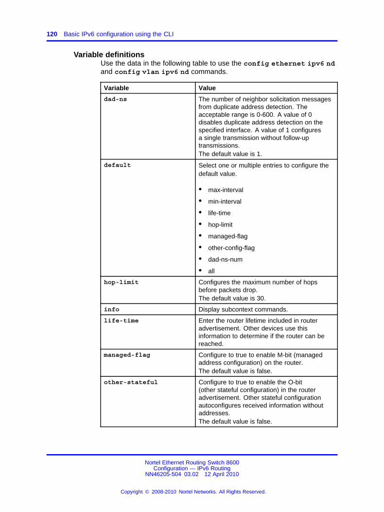
120 Basic IPv6 configuration using the CLI
Variable definitionsUse the data in the following table to use the config ethernet ipv6 ndand config vlan ipv6 nd commands.
Variable Value
dad-ns The number of neighbor solicitation messagesfrom duplicate address detection. Theacceptable range is 0-600. A value of 0disables duplicate address detection on thespecified interface. A value of 1 configuresa single transmission without follow-uptransmissions.The default value is 1.
default Select one or multiple entries to configure thedefault value.
• max-interval
• min-interval
• life-time
• hop-limit
• managed-flag
• other-config-flag
• dad-ns-num
• all
hop-limit Configures the maximum number of hopsbefore packets drop.The default value is 30.
info Display subcontext commands.
life-time Enter the router lifetime included in routeradvertisement. Other devices use thisinformation to determine if the router can bereached.
managed-flag Configure to true to enable M-bit (managedaddress configuration) on the router.The default value is false.
other-stateful Configure to true to enable the O-bit(other stateful configuration) in the routeradvertisement. Other stateful configurationautoconfigures received information withoutaddresses.The default value is false.
Nortel Ethernet Routing Switch 8600Configuration — IPv6 Routing
NN46205-504 03.02 12 April 2010
Copyright © 2008-2010 Nortel Networks. All Rights Reserved.
.

Adding static entries to the neighbor cache 121
Variable Value
route-advertisement Enable or disable periodic routeradvertisement messages.The default value is true.
rtr-advert min <value>: The minimum time allowedbetween sending unsolicited multicast routeradvertisements.
The default value is 200.
max <value>: The maximum time allowedbetween sending unsolicited multicast routeradvertisements from the interface, in seconds.(3-200 seconds).
The default value is 600.
Adding static entries to the neighbor cacheThe neighbor cache is populated with information about IPv6 neighbors towhich the IPv6 device sends traffic. You can add neighbors to the cachemanually.
Procedure steps
Step Action
1 Add a neighbor by using the following command:
config ipv6 neighbor add ports <slot/port> ipv6addr<ipv6 address> mac <mac address> vlanid <vlan id>
--End--
Variable definitionsUse the data in the following table to use the config ipv6 neighboradd ports command.
Variable Value
ipv6 address Specifies the IPv6 address inhexadecimal colon format {stringlength 0..128}
mac address Specifies the MAC address in thefollowing format: {0x00:0x00:0x00:0x00:0x00:0x00}
Nortel Ethernet Routing Switch 8600Configuration — IPv6 Routing
NN46205-504 03.02 12 April 2010
Copyright © 2008-2010 Nortel Networks. All Rights Reserved.
.

122 Basic IPv6 configuration using the CLI
Variable Value
slot/port Specifies the slot and port location toadd a neighbor for a brouter port.
vlan id Specifies the ID of the VLAN to add aneighbor for a VLAN.
Example of adding static entries to the neighbor cacheProcedure steps
Step Action
1 Add a VLAN static entry.
ERS-8610:5#config ipv6 neighbor add ports 4/17ipv6addr 9999:0:0:0:0:0:0:1 mac 00:80:2d:c0:92:03vlanid 14
2 Add a brouter port static entry.
ERS-8610:5#config ipv6 neighbor add ports 4/18ipv6addr 4040:0:0:0:0:0:0:1 mac 00:80:2d:c0:92:03
--End--
Deleting an IPv6 address from the Ethernet SF/CPU slotYou can assign multiple addresses to the Ethernet SF/CPU slot on theNortel Ethernet Routing Switch 8600. Delete an address to remove it fromthe configuration.
Procedure steps
Step Action
1 Remove an IPv6 address from the Ethernet SF/CPU slot byusing the following command:
config sys net6-mgmt ipv6 del <IPv6 address/prefixlength> cpu-slot <slot-id>
--End--
Variable definitionsUse the data in the following table to use the config sys net6-mgmtipv6 del command.
Nortel Ethernet Routing Switch 8600Configuration — IPv6 Routing
NN46205-504 03.02 12 April 2010
Copyright © 2008-2010 Nortel Networks. All Rights Reserved.
.

Deleting an IPv6 address 123
Variable Value
IPv6 address/prefix length Specifies the IPv6 address and prefixlength to delete from the port.
slot-id Specifies the slot number wherethe port is located. If a slot ID is notspecified, the address is deleted fromthe current SF/CPU.
Deleting an IPv6 addressDelete the IPv6 address to stop IPv6 routing.
Procedure steps
Step Action
1 Delete the IPv6 address on a VLAN by using the followingcommand:
config vlan <vlan id> ipv6 delete addr <Ipv6address>
2 Delete the IPv6 address on a brouter port by using the followingcommand:
config ethernet <slot/port> ipv6 delete addr <IPv6address>
--End--
Variable definitionsUse the data in the following table to use the config vlan ipv6 deleteaddr and config ethernet ipv6 delete addr commands.
Variable Value
IPv6 address Specifies the IPv6 address to delete.
slot/port Specifies the slot and port location ofthe brouter port from which to deletethe IPv6 address.
vlan id Specifies the ID of the VLAN fromwhich to delete the IPv6 address.
Example of deleting an IPv6 addressProcedure steps
Step Action
1 Delete the IPv6 address on a VLAN:
Nortel Ethernet Routing Switch 8600Configuration — IPv6 Routing
NN46205-504 03.02 12 April 2010
Copyright © 2008-2010 Nortel Networks. All Rights Reserved.
.
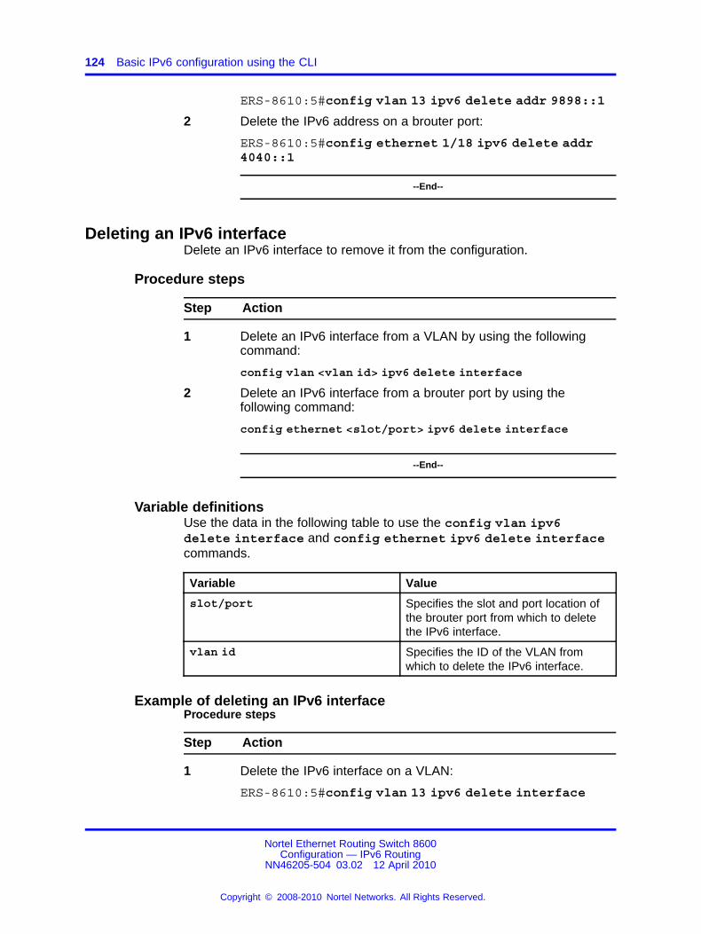
124 Basic IPv6 configuration using the CLI
ERS-8610:5#config vlan 13 ipv6 delete addr 9898::1
2 Delete the IPv6 address on a brouter port:
ERS-8610:5#config ethernet 1/18 ipv6 delete addr4040::1
--End--
Deleting an IPv6 interfaceDelete an IPv6 interface to remove it from the configuration.
Procedure steps
Step Action
1 Delete an IPv6 interface from a VLAN by using the followingcommand:
config vlan <vlan id> ipv6 delete interface
2 Delete an IPv6 interface from a brouter port by using thefollowing command:
config ethernet <slot/port> ipv6 delete interface
--End--
Variable definitionsUse the data in the following table to use the config vlan ipv6delete interface and config ethernet ipv6 delete interfacecommands.
Variable Value
slot/port Specifies the slot and port location ofthe brouter port from which to deletethe IPv6 interface.
vlan id Specifies the ID of the VLAN fromwhich to delete the IPv6 interface.
Example of deleting an IPv6 interfaceProcedure steps
Step Action
1 Delete the IPv6 interface on a VLAN:
ERS-8610:5#config vlan 13 ipv6 delete interface
Nortel Ethernet Routing Switch 8600Configuration — IPv6 Routing
NN46205-504 03.02 12 April 2010
Copyright © 2008-2010 Nortel Networks. All Rights Reserved.
.

Modifying interface parameters 125
2 Delete the IPv6 interface on a brouter port:
ERS-8610:5#config ethernet 1/18 ipv6 deleteinterface
--End--
Modifying interface parametersModify interface parameters to update configured settings for VLAN orbrouter port parameters.
Procedure steps
Step Action
1 Modify parameters for a VLAN by using the following command:
config vlan <vlan id> ipv6
2 Modify parameters for a brouter port by using the followingcommand:
config ethernet <slot/port> ipv6
--End--
Variable definitionsUse the data in the following table to use the config vlan ipv6 andconfig ethernet ipv6 commands.
Variable Value
admin Enables or disables the interface.
create Creates an interface and configures thefollowing:• link-local
• descr: modify the description for theinterface.
• addr: modify the IPv6 address for theinterface.
• addr-type: unicast or anycastThe default value is unicast.
delete Deletes one of the following:• addr
• all
• interface
Nortel Ethernet Routing Switch 8600Configuration — IPv6 Routing
NN46205-504 03.02 12 April 2010
Copyright © 2008-2010 Nortel Networks. All Rights Reserved.
.

126 Basic IPv6 configuration using the CLI
Variable Value
mcast Enables or disables the multicastadministrative status of the interface.The default value is disable.
mtu Configures the maximum transmission unit inbytes for the interface.The default value is 1500.
reachable-time Configures the time (in milliseconds) aneighbor is considered reachable afterreceiving a reachability confirmation.The default value is 30000.
retransmit-timer Configures the time (in milliseconds) betweenretransmissions of Neighbor Solicitationmessages to a neighbor when resolving theaddress or when probing the reachability of aneighbor.The default value is 1000.
slot/port Specifies the slot and port location of thebrouter port.
vlan id Specifies the ID of the VLAN from 1-4094.
Deleting a management routeDelete a management route to stop communication between networks.
Procedure steps
Step Action
1 Delete a management route by using the following command:
config sys net6-mgmt route del <network IPv6address> <network gateway>
--End--
Variable definitionsUse the data in the following table to use the config sys net6-mgmtroute del command.
Variable Value
network gateway Specifies the IPv6 address of thegateway.
network IPv6 address Specifies the IPv6 address of thenetwork to delete.
Nortel Ethernet Routing Switch 8600Configuration — IPv6 Routing
NN46205-504 03.02 12 April 2010
Copyright © 2008-2010 Nortel Networks. All Rights Reserved.
.

Deleting a neighbor discovery prefix 127
Deleting a neighbor discovery prefixDelete a neighbor discovery prefix to remove it from the configuration.
Procedure steps
Step Action
1 Delete a neighbor discovery prefix from a VLAN by using thefollowing command:
config vlan <vlan id> ipv6 nd-prefix <prefix/length>delete
2 Delete a neighbor discovery prefix from a brouter port by usingthe following command:
config ethernet <slot/port> ipv6 nd-prefix<prefix/length> delete
--End--
Variable definitionsUse the data in the following table to use the config vlan ipv6nd-prefix delete and config ethernet ipv6 nd-prefix deletecommand.
Variable Value
prefix/length Specifies the IP address and prefix.
slot/port Specifies the slot and port location ofthe brouter port.
vlan id Specifies the ID of the VLAN from1-4094.
Example of deleting a neighbor discovery prefixProcedure steps
Step Action
1 Delete a neighbor discovery prefix from a VLAN:
ERS-8610:5#config vlan 13 ipv6 nd-prefix9898::0/96 delete
2 Delete a neighbor discovery prefix from a brouter port:
ERS-8610:5#config ethernet 1/18 ipv6 nd-prefix4040::0/96 delete
--End--
Nortel Ethernet Routing Switch 8600Configuration — IPv6 Routing
NN46205-504 03.02 12 April 2010
Copyright © 2008-2010 Nortel Networks. All Rights Reserved.
.

128 Basic IPv6 configuration using the CLI
Removing an entry from the neighbor cacheRemove an entry from the neighbor cache to delete it from the staticconfiguration.
Procedure steps
Step Action
1 Remove an entry by using the following command:
config ipv6 neighbor delete <ipv6 address> port<slot/port> vlanid <vlan id>
--End--
Variable definitionsUse the data in the following table to use the config ipv6 neighbordelete command.
Variable Value
ipv6 address Specifies the IPv6 address inhexadecimal colon format (stringlength 0-128).
slot/port Specifies the slot and port location toremove a neighbor for a brouter port.
vlan id Specifies the ID of the VLAN toremove a neighbor for a VLAN.
Example of removing an entry from the neighbor cacheProcedure steps
Step Action
1 Remove a VLAN entry from the neighbor cache:
ERS-8610:5#config ipv6 neighbor delete8888:0:0:0:0:0:0:1 vlanid 13
--End--
Nortel Ethernet Routing Switch 8600Configuration — IPv6 Routing
NN46205-504 03.02 12 April 2010
Copyright © 2008-2010 Nortel Networks. All Rights Reserved.
.

129.
Basic IPv6 configuration using theNNCLI
This section describes how to use the Nortel command line interface(NNCLI) to perform basic IPv6 connectivity configuration.
Basic IPv6 configuration navigation• “Job aid: Roadmap of basic IPv6 NNCLI commands” (page 129)
• “Assigning an IPv6 address to the management port” (page 131)
• “Configuring a management route” (page 132)
• “Configuring a management virtual IPv6 address” (page 133)
• “Creating a VLAN” (page 133)
• “Configuring an interface as an IPv6 interface” (page 135)
• “Configuring the VLAN as an IPv6 VLAN” (page 136)
• “Configuring IPv6 ICMP” (page 138)
• “Configuring neighbor discovery prefixes” (page 139)
• “Configuring route advertisement” (page 140)
• “Adding static entries to the neighbor cache” (page 142)
Job aid: Roadmap of basic IPv6 NNCLI commandsThe following table lists the commands and parameters that you use toperform the procedures in this section.
Table 9Job aid: Roadmap of basic IPv6 NNCLI commands
Command Parameter
Global Configuration mode
Nortel Ethernet Routing Switch 8600Configuration — IPv6 Routing
NN46205-504 03.02 12 April 2010
Copyright © 2008-2010 Nortel Networks. All Rights Reserved.
.

130 Basic IPv6 configuration using the NNCLI
Table 9Job aid: Roadmap of basic IPv6 NNCLI commands (cont’d.)
Command Parameter
error-interval <0 through 2147483647>
redirect-msg
ipv6 icmp
unreach-msg
ipv6 mgmt-virtual <ipv6address/prefixlen>
--
ipv6 neighbor <ipv6 address> port <slot/port> mac <mac address> vlan<vlan id>
<IPv6 address/prefix length>net6-mgmt ipv6
route <network IPv6 address>
name <value>vlan create <vid>
type <value>
Interface Configuration mode
address-type <1-2>
enable
link-local <word>
mtu <bytes>
multicast-routing
name
reachable-time <ms>
retransmit-time <ms>
ipv6 interface
vlan <vlan id>
address-type <1-2>
link-local <word>
mtu <bytes>
multicast-routing
reachable-time <ms>
ipv6 interface address <ipv6address>
retransmit-time <ms>
Nortel Ethernet Routing Switch 8600Configuration — IPv6 Routing
NN46205-504 03.02 12 April 2010
Copyright © 2008-2010 Nortel Networks. All Rights Reserved.
.

Assigning an IPv6 address to the management port 131
Table 9Job aid: Roadmap of basic IPv6 NNCLI commands (cont’d.)
Command Parameter
dad-ns
hop-limit
managed-config-flag
other-config-flag
ra-lifetime
rtr-advert-max-interval
rtr-advert-min-interval
ipv6 nd
send-ra
infinite
no-advertise
preferred-life <seconds>
ipv6 nd prefix <prefix/prefixlength>
valid-life <seconds>
no-autoconfig <false|true>
eui <1-3>
no-advertise
ipv6 nd prefix-interface<Ipv6address-prefix>
no-onlink <false|true>
Assigning an IPv6 address to the management portThe Nortel Ethernet Routing Switch 8600 switch contains an Ethernet portin the SF/CPU slot. You can assign IPv6 addresses to this port to managethe device.
Perform duplicate address detection (DAD) for the management IPv6address.
ATTENTIONDo not advertise the management route to the regular routing domain (OSPFv3)or advertise the prefix information for the management interface in routeradvertisement.
Prerequisites
• You must log on to the Global Configuration mode in the NNCLI.
Nortel Ethernet Routing Switch 8600Configuration — IPv6 Routing
NN46205-504 03.02 12 April 2010
Copyright © 2008-2010 Nortel Networks. All Rights Reserved.
.

132 Basic IPv6 configuration using the NNCLI
Procedure steps
Step Action
1 Assign an IPv6 address to the management port by using thefollowing command:
net6-mgmt ipv6 <IPv6 address/prefix length>
--End--
Variable definitionsUse the data in the following table to use the net6-mgmt ipv6 command.
Variable Value
IPv6 address/prefix length Specifies the IPv6 address and prefixlength to assign to the managementinterface.The default value is none.
Configuring a management routeConfigure a management route to establish communication betweennetworks.
Prerequisites
• You must log on to the Global Configuration mode in the NNCLI.
Procedure steps
Step Action
1 Configure the management route by using the followingcommand:
net6-mgmt ipv6 route <network IPv6 address>
--End--
Variable definitionsUse the data in the following table to use the net6-mgmt ipv6 routecommand.
Nortel Ethernet Routing Switch 8600Configuration — IPv6 Routing
NN46205-504 03.02 12 April 2010
Copyright © 2008-2010 Nortel Networks. All Rights Reserved.
.

Creating a VLAN 133
Variable Value
network IPv6 address Specifies the IPv6 address and prefixlength of the network to add.The default value is none.
Configuring a management virtual IPv6 addressConfigure a system virtual IPv6 address to manage of the SF/CPUEthernet port in failover situations.
Prerequisites
• You must log on to the Global Configuration mode in the NNCLI.
Procedure steps
Step Action
1 Configure a virtual IPv6 address by using the followingcommand:
ipv6 mgmt-virtual <ipv6address/prefixlen>
--End--
Variable definitionsUse the data in the following table to use the ipv6 mgmt-virtualcommand.
Variable Value
ipv6address/prefixlen Specifies the IPv6 address and prefixlength to add to the port. To configurethis option to the default value, use thedefault operator with the command:default ipv6 mgmt-virtual.The default value is 0:0:0:0:0:0:0:0/0.
Creating a VLANYou must create a VLAN before you can configure it as an IPv6 VLAN.Nortel Ethernet Routing Switch 8600 supports three types of VLANs:
• port-based VLANs
• protocol-based VLANs
• MAC-source-based VLANs
Nortel Ethernet Routing Switch 8600Configuration — IPv6 Routing
NN46205-504 03.02 12 April 2010
Copyright © 2008-2010 Nortel Networks. All Rights Reserved.
.
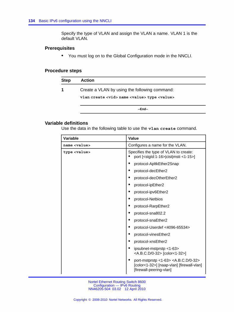
134 Basic IPv6 configuration using the NNCLI
Specify the type of VLAN and assign the VLAN a name. VLAN 1 is thedefault VLAN.
Prerequisites
• You must log on to the Global Configuration mode in the NNCLI.
Procedure steps
Step Action
1 Create a VLAN by using the following command:
vlan create <vid> name <value> type <value>
--End--
Variable definitionsUse the data in the following table to use the vlan create command.
Variable Value
name <value> Configures a name for the VLAN.
type <value> Specifies the type of VLAN to create:• port [<stgId:1-16>|cist|msti <1-15>]
• protocol-ApltkEther2Snap
• protocol-decEther2
• protocol-decOtherEther2
• protocol-ipEther2
• protocol-ipv6Ether2
• protocol-Netbios
• protocol-RarpEther2
• protocol-sna802.2
• protocol-snaEther2
• protocol-Userdef <4096-65534>
• protocol-vinesEther2
• protocol-xnsEther2
• ipsubnet-mstprstp <1-63><A.B.C.D/0-32> [color<1-32>]
• port-mstprstp <1-63> <A.B.C.D/0-32>[color<1-32>] [naap-vlan] [firewall-vlan][firewall-peering-vlan]
Nortel Ethernet Routing Switch 8600Configuration — IPv6 Routing
NN46205-504 03.02 12 April 2010
Copyright © 2008-2010 Nortel Networks. All Rights Reserved.
.
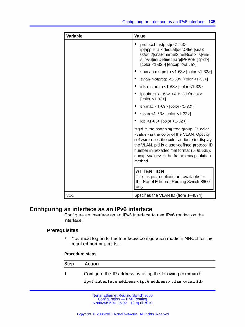
Configuring an interface as an IPv6 interface 135
Variable Value
• protocol-mstprstp <1-63>ip|appleTalk|decLat|decOther|sna802dot2|snaEthernet2|netBios|xns|vines|ipV6|usrDefined|rarp|PPPoE [<pid>][color <1-32>] [encap <value>]
• srcmac-mstprstp <1-63> [color <1-32>]
• svlan-mstprstp <1-63> [color <1-32>]
• ids-mstprstp <1-63> [color <1-32>]
• ipsubnet <1-63> <A.B.C.D/mask>[color <1-32>]
• srcmac <1-63> [color <1-32>]
• svlan <1-63> [color <1-32>]
• ids <1-63> [color <1-32>]
stgId is the spanning tree group ID. color<value> is the color of the VLAN. Optivitysoftware uses the color attribute to displaythe VLAN. pid is a user-defined protocol IDnumber in hexadecimal format (0–65535).encap <value> is the frame encapsulationmethod.
ATTENTIONThe mstprstp options are available forthe Nortel Ethernet Routing Switch 8600only.
vid Specifies the VLAN ID (from 1–4094).
Configuring an interface as an IPv6 interfaceConfigure an interface as an IPv6 interface to use IPv6 routing on theinterface.
Prerequisites
• You must log on to the Interfaces configuration mode in NNCLI for therequired port or port list.
Procedure steps
Step Action
1 Configure the IP address by using the following command:
ipv6 interface address <ipv6 address> vlan <vlan id>
Nortel Ethernet Routing Switch 8600Configuration — IPv6 Routing
NN46205-504 03.02 12 April 2010
Copyright © 2008-2010 Nortel Networks. All Rights Reserved.
.

136 Basic IPv6 configuration using the NNCLI
2 Configure additional parameters for the port by using thefollowing command:
ipv6 interface [address-type <1-2>] [mtu <bytes>][muticast-routing] [reachacble-time <ms>][retransmit-time <ms>] [vlan <vlan id>]
--End--
Variable definitionsUse the data in the following table to use the ipv6 interface and ipv6interface address commands.
Variable Value
address <ipv6 address> Configures the IPv6 address and prefixlength in the format address and prefixlength.The default value is none.
address-type <1-2> 1—unicast, 2—anycast.The default value is 1—unicast.
mtu <bytes> Configures the maximum transmission unitfor the interface.The default value is 1500.
multicast-routing Enables or disables MLD.The default value is disable.
reachable-time <ms> Configures the time, in milliseconds, thata neighbor is considered reachable afterreceiving a reachability confirmation.The default value is 30000.
retransmit-time <ms> Configures the time, in milliseconds,between retransmissions of NeighborSolicitation messages to a neighbor whenresolving the address or when probing thereachability of a neighbor.The default value is 1000.
vlan <vlan id> Specifies the VLAN ID.
Configuring the VLAN as an IPv6 VLANConfigure a VLAN as an IPv6 VLAN to use IPv6 routing on the VLAN.
Nortel Ethernet Routing Switch 8600Configuration — IPv6 Routing
NN46205-504 03.02 12 April 2010
Copyright © 2008-2010 Nortel Networks. All Rights Reserved.
.

Configuring the VLAN as an IPv6 VLAN 137
Prerequisites
• You must log on to the VLAN Interfaces configuration mode in NNCLIfor the required VLAN ID.
• You must create the VLAN before you configure it as an IPv6 VLAN.
Procedure steps
Step Action
1 Configure the IP address by using the following command:
ipv6 interface address <ipv6 address>
2 Configure additional parameters for the VLAN by using thefollowing command:
ipv6 interface [address-type <1-2>] [mtu <bytes>][muticast-routing] [reachacble-time <ms>][retransmit-time <ms>]
--End--
Variable definitionsUse the data in the following table to use the ipv6 interface and ipv6interface address commands.
Variable Value
address <ipv6 address> Configures the IPv6 address/prefix length.The default value is none.
address-type <1-2> 1—unicast, 2—anycast.The default value is 1—unicast.
mtu <bytes> Configures the maximum transmission unitfor the interface.The default value is 1500.
multicast-routing Enables or disables MLD.The default value is disable.
reachable-time <ms> Configures the time, in milliseconds, aneighbor is considered reachable afterreceiving a reachability confirmation.The default value is 30000.
retransmit-time <ms> Configures the time, in milliseconds,between retransmissions of NeighborSolicitation messages to a neighbor whenresolving the address or when probing thereachability of a neighbor.The default value is 1000.
Nortel Ethernet Routing Switch 8600Configuration — IPv6 Routing
NN46205-504 03.02 12 April 2010
Copyright © 2008-2010 Nortel Networks. All Rights Reserved.
.

138 Basic IPv6 configuration using the NNCLI
Configuring IPv6 ICMPConfigure Internet Control Message Protocol (ICMP) to transport error andinformation messages within IPv6 packets.
To view a list of ICMP messages, see “ICMPv6 type and code” (page 439).
Prerequisites
• You must log on to the Global Configuration mode in the NNCLI.
Procedure steps
Step Action
1 Configure the ICMP rate by using the following command:
ipv6 icmp error-interval <0 through 2147483647>
2 Set the status for redirect messages by using the followingcommand:
ipv6 icmp redirect-msg
3 Configure the status for unreachable messages by using thefollowing command:
ipv6 icmp unreach-msg
--End--
Variable definitionsUse the data in the following table to use the ipv6 icmpcommand.
Variable Value
error-interval <0 through2147483647>
Configures the error interval inmilliseconds. The interval is thetime between transmission of errormessages. To configure this option tothe default value, use the defaultoperator with the command.The default value is 1000.
Nortel Ethernet Routing Switch 8600Configuration — IPv6 Routing
NN46205-504 03.02 12 April 2010
Copyright © 2008-2010 Nortel Networks. All Rights Reserved.
.

Configuring neighbor discovery prefixes 139
Variable Value
redirect-msg Configures the administrative statusfor ICMP redirect messages. Usethe no operator to remove thisconfiguration. To configure this optionto the default value, use the defaultoperator with the command.The default value is disable.
unreach-msg Configures the administrative statusfor ICMP unreachable messages.Use the no operator to remove thisconfiguration. To configure this optionto the default value, use the defaultoperator with the command.The default value is disable.
Configuring neighbor discovery prefixesIPv6 nodes on the same link use ND to discover link-layer addressesand to obtain and advertise various network parameters and reachabilityinformation. ND combines the services provided by Address ResolutionProtocol (ARP) and router discovery for IPv4. IPv6 router advertisementincludes discovery prefixes.
Prerequisites
• You must log on to the Interface Configuration mode in the NNCLI.
Procedure steps
Step Action
1 Configure discovery prefixes by using the following command:
ipv6 nd prefix-interface < Ipv6address-prefix>[no-autoconfig <false|true>] [eui <1-3>] [no-advertise][no-onlink <false|true>]
2 Configure neighbor discovery prefix parameters by using thefollowing command:
ipv6 nd prefix <prefix/prefix length> [infinite][no-advertise] [preferred-life <seconds>] [valid-life<seconds>]
--End--
Nortel Ethernet Routing Switch 8600Configuration — IPv6 Routing
NN46205-504 03.02 12 April 2010
Copyright © 2008-2010 Nortel Networks. All Rights Reserved.
.

140 Basic IPv6 configuration using the NNCLI
Variable definitionsUse the data in the following table to use the ipv6 nd prefix and ipv6nd prefix-interface commands.
Variable Value
no-autoconfig <false|true> If true, the prefix is used forautonomous address configuration.The default value is true.
eui <1-3> (1) eui (extended unique identifier)not used, (2) eui with U/L(Universal/Local bit) complementenabled, (3) eui used without u/l.The default value is eui not used.
infinite Configures the prefix as infinite.The default value is disable.
no-advertise Removes the prefix from theneighbor advertisement. Use the nooperator to remove this option. Usethe default operator to configurethis value to the default setting.The default value is disable.
no-onlink <false|true> If true, onlink determination uses theprefix. This value is placed in theL-bit field in the prefix informationoption. It is a 1-bit flag.The default value is true.
preferred-life <seconds> Configures the preferred life,in seconds. The valid range is0–3600000. Use the defaultoperator to configure this value to thedefault setting.The default value is 604800.
prefix/prefix length Specifies the IP address and prefix.
valid-life <seconds> Configures the valid life, in seconds.The valid range is 0–3600000. Usethe default operator to configurethis value to the default setting.The default value is 2592000.
Configuring route advertisementUse route advertisement to discover potential default routers in a networkand to discover link information.
Prerequisites
• You must log on to the Interface Configuration mode in the NNCLI.
Nortel Ethernet Routing Switch 8600Configuration — IPv6 Routing
NN46205-504 03.02 12 April 2010
Copyright © 2008-2010 Nortel Networks. All Rights Reserved.
.

Configuring route advertisement 141
Procedure steps
Step Action
1 Configure route advertisement on a brouter port by using thefollowing command:
ipv6 nd [dad-ns <0-600>] [hop-limit <1-255>][managed-config-flag] [other-config-flag] [ra-lifetime<0|4-9000>] [rtr-advert-max-interval <4-1800>][rtr-advert-min-interval <3-1350>] [send-ra]
--End--
Variable definitionsUse the data in the following table to use the ipv6 nd command.
Variable Value
dad-ns The number of neighbor solicitationmessages from duplicate address detection.The acceptable range is 0-600. A value of 0disables duplicate address detection on thespecified interface. A value of 1 configuresa single transmission without follow-uptransmissions. Use the default operator toconfigure this value to the default setting.The default value is 1.
hop-limit Enter the maximum number of hops beforepackets drop. Use the default operator toconfigure this value to the default setting.The default value is 30.
managed-config-flag Configure to true to enable M-bit (managedaddress configuration) on the router. Use theno operator to remove this option. Use thedefault operator to configure this value tothe default setting.The default value is false.
other-config-flag Configure to true to enable the O-bit(other stateful configuration) in the routeradvertisement. Other stateful configurationautoconfigures received information withoutaddresses. Use the no operator to removethis option. Use the default operator toconfigure this value to the default setting.The default value is false.
Nortel Ethernet Routing Switch 8600Configuration — IPv6 Routing
NN46205-504 03.02 12 April 2010
Copyright © 2008-2010 Nortel Networks. All Rights Reserved.
.

142 Basic IPv6 configuration using the NNCLI
Variable Value
ra-lifetime Enter the router lifetime included in routeradvertisement. Other devices use thisinformation to determine if the router can bereached. The range is 0 or 4–9000. Use thedefault operator to configure this value tothe default setting.The default value is 1800.
rtr-advert-max-interval Configures the maximum time allowedbetween sending unsolicited multicast routeradvertisements.
The default value is 600.
rtr-advert-min-interval Configures the minimum time allowed,in seconds (3–1350), between sendingunsolicited multicast router advertisementsfrom the interface. Use the defaultoperator to configure this value to the defaultsetting.
The default value is 200.
send-ra Enable or disable periodic routeradvertisement messages. Use the nooperator to remove this option. Use thedefault operator to configure this value tothe default setting.The default value is true.
Adding static entries to the neighbor cacheThe neighbor cache contains information about IPv6 neighbors to whichthe IPv6 device sends traffic. You can manually add neighbors to thecache.
Prerequisites
• You must log on to the Global Configuration mode in the NNCLI.
Procedure steps
Step Action
1 Add a neighbor by using the following command:
Nortel Ethernet Routing Switch 8600Configuration — IPv6 Routing
NN46205-504 03.02 12 April 2010
Copyright © 2008-2010 Nortel Networks. All Rights Reserved.
.

Adding static entries to the neighbor cache 143
ipv6 neighbor <ipv6 address> port <slot/port> mac <macaddress> vlan <vlan id>
--End--
Variable definitionsUse the data in the following table to use the ipv6 neighbor command.
Variable Value
ipv6 address Specifies the IPv6 address inhexadecimal colon format {stringlength 0..128}. The default value isnone.
mac address Specifies the MAC address in thefollowing format: {0x00:0x00:0x00:0x00:0x00:0x00}
slot/port Specifies the slot and port location toadd a neighbor for a brouter port.
vlan id Specifies the ID of the VLAN to add aneighbor for a VLAN.
Example of adding static entries to the neighbor cacheProcedure steps
Step Action
1 Add a VLAN static entry:
ERS-8606:5(config)#ipv6 neighbor 9999:0:0:0:0:0:0:1 port 4/1 mac 00:80:2d:c0:92:03 vlan 4
--End--
Nortel Ethernet Routing Switch 8600Configuration — IPv6 Routing
NN46205-504 03.02 12 April 2010
Copyright © 2008-2010 Nortel Networks. All Rights Reserved.
.

144 Basic IPv6 configuration using the NNCLI
Nortel Ethernet Routing Switch 8600Configuration — IPv6 Routing
NN46205-504 03.02 12 April 2010
Copyright © 2008-2010 Nortel Networks. All Rights Reserved.
.

145.
IPv6 routing configuration usingEnterprise Device Manager
This chapter describes Enterprise Device Manager procedures to configureIPv6 static routes and the Open Shortest Path First version 3 (OSPFv3)protocol in the Ethernet Routing Switch 8600. Routers exchange networktopology information with the Open Shortest Path First (OSPF) protocol.For conceptual information relating to static routes and OSPF, see “IPv6routing fundamentals” (page 25).
IPv6 routing configuration navigation• “Creating IPv6 static routes” (page 145)
• “Creating a static default route” (page 147)
• “Enabling OSPF on a router” (page 148)
• “Creating OSPF port interfaces” (page 151)
• “Creating OSPF VLAN interfaces” (page 155)
• “Adding NBMA neighbors” (page 158)
• “Creating OSPF areas” (page 160)
• “Creating a virtual link” (page 162)
• “Specifying ASBRs” (page 164)
• “Inserting OSPF area aggregate ranges” (page 165)
• “Configuring route redistribution” (page 166)
Creating IPv6 static routesTo improve the static route management, you can change static routesdirectly with the IPv6 static routing table manager. The static routing tableis separate from the system routing table, which the router uses to controlforwarding. Although the tables are separate, entries in the static routing
Nortel Ethernet Routing Switch 8600Configuration — IPv6 Routing
NN46205-504 03.02 12 April 2010
Copyright © 2008-2010 Nortel Networks. All Rights Reserved.
.

146 IPv6 routing configuration using Enterprise Device Manager
table manager automatically change in the system routing table if thenext-hop address in the static route is reachable and the static route isenabled.
Use static routes to manually configure routes to destination IPv6 addressprefixes.
Procedure steps
Step Action
1 In the navigation tree, open the following folders: Configuration,IPv6.
2 Double-click IPv6.
3 Click the Static Routes tab.
4 Click Insert.
5 In the Dest box, type the IPv6 address.
6 In the PrefixLength box, type the length of the prefix for the IPv6address.
7 In the NextHop box, type the IPv6 address of the router throughwhich the specified route is accessible.
8 In the IfIndex box, click Port, VLAN, or Tunnel and select anoption.
9 In the Cost box, type a number for the distance.
10 Select the Enable check box.
11 In the Preference box, type the route preference.
12 Click Insert.
The new route appears in the Static Routes tab.
--End--
Variable definitionsUse the data in the following table to configure the static route.
Variable Value
Dest Configures the IPv6 destination network address. The prefixvalue must match the PrefixLength.
PrefixLength Configures the number of leading one bits that form the maskas a logical value. The prefix value must match the value inthe Dest box. The range is 0–128.
NextHop Configures the next hop IPv6 address.
Nortel Ethernet Routing Switch 8600Configuration — IPv6 Routing
NN46205-504 03.02 12 April 2010
Copyright © 2008-2010 Nortel Networks. All Rights Reserved.
.

Creating a static default route 147
Variable Value
IfIndex Select the required VLAN, port, or tunnel.
Cost Configures the cost or distance ratio to reach the destinationfor this node. The range is 1–65535.The default value is 1.
Enable Configures whether the configured static route is available onthe port. The default is enable.
ATTENTIONIf a static route is disabled, you must enable it before youcan add the route to the system routing table.
Status Indicates the current status of this entry.
Preference Configures the routing preference of the destination IPv6address. The range is 1-255.The default value is 5.
Creating a static default routeYou can statically configure the routing switches with the default routestatically, or routing switches can learn the default route through a dynamicrouting protocol (RFC1812).
ATTENTIONYou must configure the destination address and subnet mask for the defaultstatic route to 0::0.
Procedure steps
Step Action
1 In the navigation tree, open the following folders: Configuration,IPv6.
2 Double-click IPv6.
3 Click the Static Routes tab.
4 Click Insert.
5 In theDest box, type 0::0.
6 In the PrefixLength box, type 0.
7 In the NextHop box, select the router that leads to the specifiedroute.
8 In the IfIndex box, click Port or VLAN and select an option.
9 Click Insert.
Nortel Ethernet Routing Switch 8600Configuration — IPv6 Routing
NN46205-504 03.02 12 April 2010
Copyright © 2008-2010 Nortel Networks. All Rights Reserved.
.

148 IPv6 routing configuration using Enterprise Device Manager
The default route record is created in the static routing table.
--End--
Enabling OSPF on a routerWhen you configure an interface for the OSPF protocol, you must firstenable OSPF globally on the router and then assign an IPv6 address.
Procedure steps
Step Action
1 In the navigation tree, open the following folders: Configuration,IPv6.
2 Double-click OSPF.
3 In the AdminStat option box, select enabled to activate OSPF,or select disabled to deactivate OSPF.
4 Click Apply.
The OSPF protocol is enabled (or disabled) on this router.
5 Click Yes to confirm the forced SPF run.
The router performs the SPF run and the OSPF link statedatabase is updated.
ATTENTIONAfter initiating an SPF run, wait 10 seconds before you initiateanother SPF run.
--End--
Variable definitionsUse the data in the following table to configure OSPF.
Variable Value
RouterID Identifies the router independent of other routersin the OSPF domain. The IPv6 Router ID uses thesame format as an IPv4 address.
AdminStat The administrative status of OSPF in the router.The value enabled activates OSPF on at leastone interface; disabled deactivates OSPF on allinterfaces. The default is disabled.
VersionNumber Current version number of OSPF.
Nortel Ethernet Routing Switch 8600Configuration — IPv6 Routing
NN46205-504 03.02 12 April 2010
Copyright © 2008-2010 Nortel Networks. All Rights Reserved.
.

Enabling OSPF on a router 149
Variable Value
AreaBdrRtrStatus A read-only flag identifying this router as an areaborder router (ABR).
ATTENTIONThe AreaBdrRtrStatus value must be true tocreate a virtual router interface.
ASBdrRtrStatus When you select the ASBdrRtrStatus option, therouter is configured as an autonomous systemboundary router (ASBR).The default is false.
AsScopeLsaCount A read-only field displaying the number of external(LS type 5) link-state advertisements in thelink-state database.
AsScopeLsaCksumSum A read-only field displaying the 32-bit unsignedsum of the LS checksums of the external link-stateadvertisements in the link-state database. Thissum determines changes and compares thelink-state databases of two routers.
OriginateNewLsas A read-only field displaying the number ofnew link-state advertisements. The number isincremented each time the router originates a newLSA.
RxNewLsas A read-only field displaying the number ofnew link-state advertisements received. Thisnumber does not include new instantiations ofself-originated link-state advertisements.
ExtLsaCount A read-only field displaying the number of externalLSAs (LS type 0x4005) in the link-state database.
ExtAreaLsdLimit The maximum number of nondefault AS-externalLSAs entries stored in the link-state database(LSDB). If the value is -1,no limit exists. Thedefault is -1.
You must configure the ExtAreaLsdbLimit to thesame value for all routers attached to the OSPFv3backbone or any regular OSPFv3 area (that is,exclude OSPFv3 stub areas and NSSAs).
Nortel Ethernet Routing Switch 8600Configuration — IPv6 Routing
NN46205-504 03.02 12 April 2010
Copyright © 2008-2010 Nortel Networks. All Rights Reserved.
.

150 IPv6 routing configuration using Enterprise Device Manager
Variable Value
MulticastExtentions A bit mask indicating whether the router isforwarding IPv6 multicast datagrams based on thealgorithms defined in the multicast extensions toOSPF. Possible forwarding includes:
• intraAreaMulticast forwards to directly attachedareas (called intra-area multicast routing)
• interAreaMulticast forwards between OSPFv3areas (called inter-area multicast routing)
• interAsMulticast forwards between autonomoussystems (called inter-AS multicast routing)
By default, all bits are cleared.
ExitOverflowInterval The number of seconds after entering theoverflow state, that a router attempts to leave theoverflow state. The router resends nondefaultAS-external-LSAs. When the value is configured to0, the router does not leave the overflow state untilthe router restarts.The default value is 4294967295.
DemandExtentions The router support for demand routing.The default value is disabled.
TrafficEngineeringSupport The router support for traffic engineeringextensions.The default value is disabled.
ReferenceBandwidth The reference bandwidth in kilobits per second forcalculating default interface metrics. The defaultvalue is 100 000 Kbps (100 Mb/s).
RestartSupport The router support for OSPF hitless restart.Options include no restart support, only plannedrestarts, or both planned and unplanned restarts.Options include:
• none (default)
• plannedOnly
• plannedAndUnplanned
RestartStatus A read-only field indicating the current status ofOSPF hitless restart:
• notRestarting (default)
• plannedRestart
• unplannedRestart
Nortel Ethernet Routing Switch 8600Configuration — IPv6 Routing
NN46205-504 03.02 12 April 2010
Copyright © 2008-2010 Nortel Networks. All Rights Reserved.
.

Creating OSPF port interfaces 151
Variable Value
RestartInterval The configured OSPF hitless restart timeoutinterval in the range 1–1800 seconds. The defaultis 1800.
RestartAge A read-only field indicating the remaining timein the current OSPF hitless restart interval inseconds. The range is 1–1800.
RestartExitReason A read-only field indicating the outcome of the lastattempt at a hitless restart. Options include thefollowing:
• none indicates no restart was attempted.
• inProgress indicates a restart attempt iscurrently underway.
• completed indicates a completed restart.
• timedout indicates a timed-out restart.
• topologyChanged indicates a cancelled restartdue to topology change.
The default is none.
Creating OSPF port interfacesYou configure an OSPF interface, or link, on an IP interface. In the NortelEthernet Routing Switch 8600, an IP interface is either a single link(brouter port) or a logical interface configured on a VLAN (multiple ports).The underlying lower level protocols and the routing protocol itself obtainthe state information associated with the interface.
When you enable an OSPF interface, you designate the interface as oneof the following types:
• broadcast (active)
• nonbroadcast multiaccess (NBMA)
• point-to-point
• point-to-multipoint
ATTENTIONWhen you enable an OSPF interface, you cannot change the interface type. Youmust first disable the interface. After you disable the interface, you can changethe type and reenable it. On NMBA interfaces, you must also delete all manuallyconfigured neighbors before you change the type.
Prerequisites
Nortel Ethernet Routing Switch 8600Configuration — IPv6 Routing
NN46205-504 03.02 12 April 2010
Copyright © 2008-2010 Nortel Networks. All Rights Reserved.
.

152 IPv6 routing configuration using Enterprise Device Manager
• Before you can configure the OSPF protocol on a router interface,you must first enable OSPF globally on the router and assign an IPv6address to the interface.
Procedure steps
Step Action
1 In the Device Physical View tab, select the port to configure.
2 In the navigation tree, open the following folders: Configuration,Edit, Port.
3 Double-click IPv6.
4 Select the IPv6 OSPF Interface tab.
5 Click Insert.
6 In the AreaId box, click the ellipsis (...) button to select the ID.
7 In the Type box, select the type of OSPF interface you want tocreate: broadcast, nbma, pointToPoint or pointToMultipoint.
8 In the AdminState box, select enabled.
9 In the RtrPriority box, modify the value if required.
10 In the TransitDelay, RetransitInterval, HelloInterval,RtrDeadInterval, and PollInterval boxes, modify values asrequired.
11 In the Metric Value box, type the metric value for a demand foran instance.
12 In the InstId box, type the instance ID.
13 Click Insert.
14 On the Interfaces tab, click Apply.
--End--
Variable definitionsUse the data in the following table to configure an OSPF port interface.
Variable Value
Index The interface index of this OSPFv3 interface. Theindex corresponds to the interface index of theIPv6 interface where OSPFv3 is configured.
Nortel Ethernet Routing Switch 8600Configuration — IPv6 Routing
NN46205-504 03.02 12 April 2010
Copyright © 2008-2010 Nortel Networks. All Rights Reserved.
.

Creating OSPF port interfaces 153
Variable Value
AreaId Dotted decimal value to designate the OSPF areaname.
VLANs maintaining the default area setting on theinterface cause the LSDB to be inconsistent.
ATTENTIONThe area name is not related to an IPv6 address.You can use any value for the OSPF area name(for example, 1.1.1.1 or 200.200.200.200).
Type Type of OSPF interface (broadcast, nbma,point-to-point, or point-to-multipoint).
AdminStat Current administrative state of the OSPF interface(enabled or disabled).
Rtrpriority OSPF priority for the interface during the electionprocess for the designated router. The interfacewith the highest priority number is the designatedrouter. The interface with the second-highestpriority becomes the backup designated router.If the priority is 0, the interface cannot becomethe designated router or the backup. The priorityis used only during election of the designatedrouter and backup designated router. The range is0–255. The default is 1.
TransitDelay Length of time, in seconds (1–1800), required totransmit an LSA update packet over the interface.The default value is 1.
RetransInterval Length of time, in seconds (1–1800), requiredbetween LSA retransmissions.The default value is 5.
HelloInterval Length of time, in seconds, between hello packets.This value must be the same for all routersattached to a common network. The default is 10seconds.
ATTENTIONWhen you change the Hello interval values, youmust save the configuration file and reboot theswitch for the values to be restored and checkedfor consistency.
Nortel Ethernet Routing Switch 8600Configuration — IPv6 Routing
NN46205-504 03.02 12 April 2010
Copyright © 2008-2010 Nortel Networks. All Rights Reserved.
.

154 IPv6 routing configuration using Enterprise Device Manager
Variable Value
RtrDeadInterval Adjacent routers use this interval to determineif the router is removed from the network. Theinterval must be identical on all routers on thesubnet and a minimum of four times the hellointerval. To avoid interpretability issues, theRtrDeadInterval value for the OSPF interface mustmatch the RtrDeadInterval value for the OSPFvirtual interface. The default is 40 seconds.
PollInterval Length of time, in seconds, between hello packetssent to an inactive OSPF router. The default valueis 120.
State A read-only field indicating the OSPFv3 interfacestate. Options include:
• down
• loopback
• waiting
• pointToPoint
• designatedRouter
• backupDesignatedRouter
• otherDesignatedRouter
DesignatedRouter A read-only field indicating the router ID of thedesignated router.
BackupDesignatedRouter A read-only field indicating the router ID of thebackup designated router.
Events A read-only field indicating the number of timesthis OSPF interface changed state or an erroroccurred.
MetricValue The metric assigned to this interface. The defaultmetric value is the reference bandwidth or ifSpeed.The value of the reference bandwidth is configuredby the rcOspfv3ReferenceBandwidth object.
LinkScopeLsaCount A read-only field indicating the number ofLink-Scope link-state advertisements in thelink-state database.
LinkLsaChksumSum A read-only field indicating the 32-bit unsignedsum of the Link-Scope link-state advertisementLS checksums in the link-state database. Thesum determines a change in the router link-statedatabase and compares the link-state database oftwo routers.
Nortel Ethernet Routing Switch 8600Configuration — IPv6 Routing
NN46205-504 03.02 12 April 2010
Copyright © 2008-2010 Nortel Networks. All Rights Reserved.
.

Creating OSPF VLAN interfaces 155
Creating OSPF VLAN interfacesYou configure an OSPF interface, or link, on an IP interface. In the NortelEthernet Routing Switch 8600, an IP interface is either a single link(brouter port) or a logical interface configured on a VLAN (multiple ports).The underlying low level protocols and the routing protocol itself obtain thestate information associated with the interface.
When you enable an OSPF interface, you designate the interface as oneof the following types:
• broadcast (active)
• nonbroadcast multiaccess (NBMA)
• point-to-point
• point-to-multipoint
ATTENTIONWhen you enable an OSPF interface, you cannot change the interface type. Youmust first disable the interface. After you disable the interface, you can changethe type and reenable it. On NMBA interfaces, you must also delete all manuallyconfigured neighbors before you change the type.
Prerequisites
• Before you can configure the OSPF protocol on a router interface,you must first enable OSPF globally on the router and assign an IPv6address to the interface.
Procedure steps
Step Action
1 In the navigation tree, open the following folders: Configuration,VLAN.
2 Double-click VLANs.
3 In the Basic tab, select the VLAN for which to configure an OSPFinterface.
4 Click IPv6.
5 Click the IPv6 OSPF Interface tab.
6 Click Insert.
7 In the AreaId box, click the ellipsis (...) button to select the ID.
8 In the Type box, select the type of OSPF interface to create:broadcast, nbma, pointToPoint, or pointToMultipoint.
9 In the AdminState box, select enabled.
10 In the RtrPriority box, modify the value if required.
Nortel Ethernet Routing Switch 8600Configuration — IPv6 Routing
NN46205-504 03.02 12 April 2010
Copyright © 2008-2010 Nortel Networks. All Rights Reserved.
.

156 IPv6 routing configuration using Enterprise Device Manager
11 In the TransitDelay, RetransitInterval, HelloInterval,RtrDeadInterval, and PollInterval boxes, modify values asrequired.
12 In the Metric Value box, type the metric value for a demand foran instance.
13 In the InstId box, type the instance ID.
14 Click Insert.
15 On the Interfaces tab, click Apply.
--End--
Variable definitionsUse the data in the following table to configure an OSPF VLAN interface.
Variable Value
Index The interface index of this OSPFv3 interface. Theindex corresponds to the interface index of theIPv6 interface where OSPFv3 is configured.
AreaId Dotted decimal value to designate the OSPF areaname.
VLANs maintaining the default area setting on theinterface cause the LSDB to be inconsistent.
ATTENTIONThe area name is not related to an IPv6 address.You can use any value for the OSPF area name(for example, 1.1.1.1 or 200.200.200.200).
Type Type of OSPF interface (broadcast, nbma,point-to-point, or point-to-multipoint).
AdminStat Current administrative state of the OSPF interface(enabled or disabled).
Rtrpriority OSPF priority for the interface during the electionprocess for the designated router. The interfacewith the highest priority number is the designatedrouter. The interface with the second-highestpriority becomes the backup designated router.If the priority is 0, the interface cannot becomethe designated router or the backup. The priorityis used only during election of the designatedrouter and backup designated router. The range is0—255. The default is 1.
Nortel Ethernet Routing Switch 8600Configuration — IPv6 Routing
NN46205-504 03.02 12 April 2010
Copyright © 2008-2010 Nortel Networks. All Rights Reserved.
.

Creating OSPF VLAN interfaces 157
Variable Value
TransitDelay Length of time, in seconds (1—1800), required totransmit an LSA update packet over the interface.The default value is 1.
RetransInterval Length of time, in seconds (1—1800), requiredbetween LSA retransmissions.The default value is 5.
HelloInterval Length of time, in seconds, between hello packets.This value must be the same for all routersattached to a common network. The default is 10seconds.
ATTENTIONWhen you change the Hello interval values, youmust save the configuration file and reboot theswitch for the values to be restored and checkedfor consistency.
RtrDeadInterval Adjacent routers use this interval to determineif the router is removed from the network. Theinterval must be identical on all routers on thesubnet and a minimum of four times the HelloInterval. To avoid interpretability issues, theRtrDeadInterval value for the OSPF interface mustmatch with the RtrDeadInterval value for the OSPFvirtual interface. The default is 40 seconds.
PollInterval Length of time, in seconds, between hello packetssent to an inactive OSPF router. The default valueis 120.
State A read-only field indicating the OSPFv3 interfacestate:
• down
• loopback
• waiting
• pointToPoint
• designatedRouter
• backupDesignatedRouter
• otherDesignatedRouter
DesignatedRouter A read-only field indicating the router ID of thedesignated router.
BackupDesignatedRouter A read-only field indicating the router ID of thebackup designated router.
Nortel Ethernet Routing Switch 8600Configuration — IPv6 Routing
NN46205-504 03.02 12 April 2010
Copyright © 2008-2010 Nortel Networks. All Rights Reserved.
.

158 IPv6 routing configuration using Enterprise Device Manager
Variable Value
Events A read-only field indicating the number of timesthis OSPF interface changed state or an erroroccurred.
MetricValue The metric assigned to this interface. The defaultvalue of the metric is the reference bandwidth orifSpeed. The value of the reference bandwidth isconfigured by the rcOspfv3ReferenceBandwidthobject.
LinkScopeLsaCount A read-only field indicating the number ofLink-Scope link-state advertisements in thelink-state database.
LinkLsaChksumSum A read-only field indicating the 32-bit unsignedsum of the Link-Scope link-state advertisementLS checksums in the link-state database. Thesum determines a change in the router link-statedatabase and compares the link-state database oftwo routers.
InstId Enables multiple instances of OSPFv3 over asingle link. The switch assigns each protocolinstance a separate ID. This ID is significant forlocal links only. The default is 0.
Adding NBMA neighborsIn contrast to a broadcast network where switches multicast (send toAllSPFRouters and AllDRouters) certain OSPF protocol packets, switchesreplicate and send NBMA packets to each neighboring router as unicast.NBMA networks drop all OSPF packets with destination addressesAllSPFRouters and AllDRouters. Because the NBMA network does notbroadcast, you must manually configure a list of neighbors and prioritiesfor all routers in the network that can become the designated router (DR).Potential DRs use a positive nonzero router priority.
An NMBA interface with a positive nonzero router priority is eligibleto become the DR for the NBMA network and is configured with theidentification of all attached routers, IPv6 addresses, and router priorities.
Prerequisites
• Before you begin this configuration, identify the following:
— specific interfaces to include in the NBMA network
— the IPv6 address for each interface
— the router priority for each interface
— the HelloInterval for the network
Nortel Ethernet Routing Switch 8600Configuration — IPv6 Routing
NN46205-504 03.02 12 April 2010
Copyright © 2008-2010 Nortel Networks. All Rights Reserved.
.

Adding NBMA neighbors 159
— the RtrDeadInterval for the network
— the PollInterval for the network
After you gather the information, you can configure the interfaces and addneighbors for each interface that is eligible to become the DR.
Procedure steps
Step Action
1 In the navigation tree, open the following folders: Configuration,IPv6.
2 Double-click OSPF.
3 Click the Interfaces tab.
4 Select an NBMA interface with a positive nonzero router priority.
5 Click the NBMA Neighbors tab.
6 Click Insert.
7 In the IfIndex box, click Port or VLAN, and select the requiredinterface.
8 In the Address box, type the IPv6 address for the first neighbor.
9 In the Priority box, type the priority for the neighbor.
10 Click Insert.
--End--
Variable definitionsUse the data in the following table to configure an OSPF NBMA neighbor.
Variable Value
IfIndex The local link ID of the link over which the neighborcan be reached
Address The IPv6 address of the neighbor associated withthe local link.
Priority The priority of this neighbor in the designatedrouter election algorithm. The value 0 signifiesthat the neighbor is not eligible to become thedesignated router on this particular network.
Nortel Ethernet Routing Switch 8600Configuration — IPv6 Routing
NN46205-504 03.02 12 April 2010
Copyright © 2008-2010 Nortel Networks. All Rights Reserved.
.

160 IPv6 routing configuration using Enterprise Device Manager
Variable Value
RtrId A 32-bit integer (represented as a type IpAddress)uniquely identifying the neighboring router in theAutonomous System. A value of 0.0.0.0 is returneduntil a Hello is received from the configuredneighbor.
State The State of the relationship with this Neighbor.
Creating OSPF areasA stub area does not receive advertisements for external routes, whichreduces the size of the link-state database. A stub area uses only onearea border router. Any packets destined for outside the area are routedto the area border exit point, examined by the area border router, andforwarded to a destination.
A not so stubby area (NSSA) prevents the flooding of AS-Externallink-state advertisements into the area by replacing them with a defaultroute. NSSAs also import small stub (non-OSPF) routing domains intoOSPF.
Procedure steps
Step Action
1 In the navigation tree, open the following folders: Configuration,IPv6.
2 Double-click OSPF.
3 Click the Areas tab.
4 Click Insert.
5 Type the required values.
6 Click Insert.
7 Click Apply.
--End--
Variable definitionsUse the data in the following table to configure the OSPF area.
Nortel Ethernet Routing Switch 8600Configuration — IPv6 Routing
NN46205-504 03.02 12 April 2010
Copyright © 2008-2010 Nortel Networks. All Rights Reserved.
.
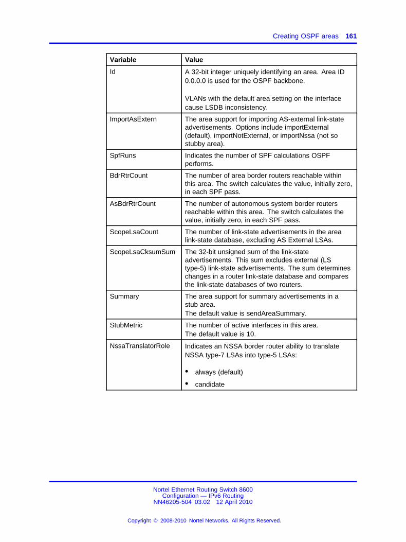
Creating OSPF areas 161
Variable Value
Id A 32-bit integer uniquely identifying an area. Area ID0.0.0.0 is used for the OSPF backbone.
VLANs with the default area setting on the interfacecause LSDB inconsistency.
ImportAsExtern The area support for importing AS-external link-stateadvertisements. Options include importExternal(default), importNotExternal, or importNssa (not sostubby area).
SpfRuns Indicates the number of SPF calculations OSPFperforms.
BdrRtrCount The number of area border routers reachable withinthis area. The switch calculates the value, initially zero,in each SPF pass.
AsBdrRtrCount The number of autonomous system border routersreachable within this area. The switch calculates thevalue, initially zero, in each SPF pass.
ScopeLsaCount The number of link-state advertisements in the arealink-state database, excluding AS External LSAs.
ScopeLsaCksumSum The 32-bit unsigned sum of the link-stateadvertisements. This sum excludes external (LStype-5) link-state advertisements. The sum determineschanges in a router link-state database and comparesthe link-state databases of two routers.
Summary The area support for summary advertisements in astub area.The default value is sendAreaSummary.
StubMetric The number of active interfaces in this area.The default value is 10.
NssaTranslatorRole Indicates an NSSA border router ability to translateNSSA type-7 LSAs into type-5 LSAs:
• always (default)
• candidate
Nortel Ethernet Routing Switch 8600Configuration — IPv6 Routing
NN46205-504 03.02 12 April 2010
Copyright © 2008-2010 Nortel Networks. All Rights Reserved.
.

162 IPv6 routing configuration using Enterprise Device Manager
Variable Value
NssaTranslatorState Indicates if and how an NSSA border router translatesNSSA type-7 LSAs into type-5 LSAs:
• enabled indicates the NSSA border router translatorrole is configured to always.
• elected indicates a candidate NSSA border router istranslating type-7 LSAs into type-5.
• disabled indicates a candidate NSSA border routeris not translating type-7 LSAs into type-5.
NssaTranslatorStabilityInterval
The number of seconds after an elected translatordetermines translation is not required that it resumestranslation duties. The default value is 40.
NssaTranslatorEvents A read-only field indicating the number of translatorstate changes since the last startup.
StubMetricType Configures the type of metric advertised as a defaultroute:
• ospfv3Metric indicates the OSPF metric
• comparableCost indicates an external type 1
• nonComparable indicates and external type 2
The default value is ospfv3Metric.
Creating a virtual linkWhen you use OSPF, an Ethernet Routing Switch 8600 that functionsas an ABR must connect directly to the backbone. If the switch does notdirectly connect, it requires a virtual link. In an Ethernet Routing Switch8600, you can automatically create virtual links or you can manuallyconfigure a virtual link.
Virtual linking is similar to backup redundancy. With virtual linkingconfigured, the switch creates a virtual link for vital traffic paths in yourOSPF configuration if traffic is interrupted, such as when an interfacecable providing connection to the backbone (either directly or indirectly) isdisconnected from the switch. Automatic virtual linking ensures that a linkis created by using another switch.
If automatic virtual linking requires more resources than you wantto expend, create manual virtual links. Manual virtual links conserveresources and provide specific control over virtual link placement in yourOSPF configuration.
Nortel Ethernet Routing Switch 8600Configuration — IPv6 Routing
NN46205-504 03.02 12 April 2010
Copyright © 2008-2010 Nortel Networks. All Rights Reserved.
.

Creating a virtual link 163
OSPF behavior is modified according to OSPF standards so that OSPFroutes cannot be learned through an ABR unless it connects to thebackbone or through a virtual link.
Procedure steps
Step Action
1 In the navigation tree, open the following folders: Configuration,IPv6.
2 Double-click OSPF.
3 Click the Virtual If tab.
4 Click Insert.
5 In the AreaId box, specify the area ID for the transit area.
The transit area is the common area between two ABRs.
6 In the Neighbor box, specify the neighbor ID.
The neighbor ID is the IP router ID of the ABR through which theother ABR must route traffic destined for the backbone.
7 Click Insert.
8 To verify that the virtual link is active, refresh the Virtual If taband check the State column.
If the state is point-to-point, the virtual link is active. If the state isdown, the virtual link is configured incorrectly.
--End--
Variable definitionsUse the data in the following table to configure the virtual link.
Variable Value
AreaId A read-only field indicating the transit area ID that thevirtual link traverses.
Neighbor A read-only field indicating the router ID of the virtualneighbor.
TransitDelay The estimated number of seconds required to transmit alink-state update packet over this interface. The range is1–1800 and the default is 1 second.
Nortel Ethernet Routing Switch 8600Configuration — IPv6 Routing
NN46205-504 03.02 12 April 2010
Copyright © 2008-2010 Nortel Networks. All Rights Reserved.
.

164 IPv6 routing configuration using Enterprise Device Manager
Variable Value
RetransInterval The number of seconds between link-state advertisement,and retransmissions, for adjacencies belonging to thisinterface. This value is also used when retransmitting thedatabase description and the link-state request packets.This value must exceed the expected round- trip time. Therange is 1–1800 and the default is 5 seconds.
HelloInterval The length of time, in seconds, between the hello packetsthat the router sends on the interface. This value must bethe same for the virtual neighbor. The default value is 10seconds.
RtrDeadInterval The number of seconds during which router hello packetsare not received before neighbors declare the router down.Use a multiple of the hello interval. You must configure thissame value on the virtual neighbor. The default value is 60seconds.
State OSPF virtual interface states.
Events The number of state changes or error events on this virtuallink
LinkScopeLsaCount
The total number of Link-Scope link-state advertisements inthis virtual link’s link-state database.
LinkLsaCksumSum
The 32-bit unsigned sum of the Link-Scope link-stateadvertisements’ LS checksums contained in this virtuallink’s link-state database. The sum can be used todetermine if there has been a change in a router’s link statedatabase, and to compare the link-state database of tworouters.
Specifying ASBRsAutonomous system boundary routers (ASBR) advertise non-OSPF routesinto OSPF domains, communicating routes throughout the OSPF routingdomain. A router can function as an ASBR if you connect one or moreinterfaces to a non-OSPF network (for example, RIP or BGP).
To conserve resources, or to specifically control which routers perform asASBRs, you can limit the number of ASBRs on your network.
Procedure steps
Step Action
1 In the navigation tree, open the following folders: Configuration,IPv6.
2 Double-click OSPF.
Nortel Ethernet Routing Switch 8600Configuration — IPv6 Routing
NN46205-504 03.02 12 April 2010
Copyright © 2008-2010 Nortel Networks. All Rights Reserved.
.

Inserting OSPF area aggregate ranges 165
3 Select the ASBdrRtrStatus box to designate the router as anASBR.
OR
Clear the box to remove ASBR status from the router.
4 Click Apply.
--End--
Inserting OSPF area aggregate rangesConfigure an area address range on the OSPF router to reduce thenumber of ABR advertisements into other OSPF areas. An area addressrange is an implied contiguous range of area network addresses for whichthe ABR advertises a single summary route.
You can use any value for the OSPF area name (for example, 1.1.1.1 or200.200.200.200).
Procedure steps
Step Action
1 In the navigation tree, open the following folders: Configuration,IPv6.
2 Double-click OSPF.
3 Click the Area Aggregate tab.
4 Click Insert.
5 In the AreaId box, click the ellipsis button (...) to select therequired area ID of the aggregate address.
6 In the AreaLsdbType box, select the required option:
• interAreaPrefixLsa: to generate an aggregated summary
• nssaExternalLink: to generate an NSSA link summary
7 In the Prefix box, type the prefix of the area IPv6 address.
8 In the Prefix Length box, type the number of bits you want toadvertise from the IPv6 address.
9 In the Effect box, select the required option:
• advertiseMatching: to advertise the aggregate summary LSAwith the same link-state ID
• doNotAdvertiseMatching: to suppress all networks that fallwithin the entire range
Nortel Ethernet Routing Switch 8600Configuration — IPv6 Routing
NN46205-504 03.02 12 April 2010
Copyright © 2008-2010 Nortel Networks. All Rights Reserved.
.

166 IPv6 routing configuration using Enterprise Device Manager
10 In the AdvertiseMetric box, type a cost value (in the range 0 to65535) to advertise for the OSPF area range.
11 Click Insert.
--End--
Variable definitionsUse the data in the following table to configure the IPv6 OSPF areaaggregate.
Variable Value
AreaID Specifies the address of an OSPFarea. Use dotted decimal notation tospecify the area name.
AreaLsdbType Specifies the LSA type.
Prefix Specifies the IPv6 address range of anOSPF area.
PrefixLength Specifies the prefix length value forthis address.
Effect Specifies the area range advertisemode as advertise or no-advertise.The default value isadvertiseMatching.
AdvertiseMetric Specifies the advertise metric value inthe range 0 to 65535.
Configuring route redistributionYou can configure a redistribute entry for OSPF to announce routes of acertain source type, such as static, RIP, or direct. If you do not configure aroute policy field for a redistribute entry, the switch uses the default actionon the basis of metric, metric-type, and subnet. The default action is calledbasic redistribution. Otherwise, the specified route policy performs detailedredistribution. If you do not configure a redistribution entry, the switchgenerates no external LSA for non-OSPF routes.
Nortel Ethernet Routing Switch 8600Configuration — IPv6 Routing
NN46205-504 03.02 12 April 2010
Copyright © 2008-2010 Nortel Networks. All Rights Reserved.
.

Configuring route redistribution 167
ATTENTIONChanging OSPF redistribute contexts is a process-oriented operation that canaffect system performance and network reachability. Nortel recommends thatyou change default preferences for an OSPF redistribute context before youenable the protocols.
Procedure steps
Step Action
1 In the navigation tree, open the following folders: Configuration,IPv6.
2 Double-click OSPF.
3 Click the Redistribute tab.
The Redistribute tab appears.
4 Click Insert.
5 Modify options as required.
6 Click Insert.
7 Click Apply.
--End--
Variable definitionsUse the data in the following table to configure the route redistribution.
Variable Value
DstVrfId Specifies the ID of the destination virtual router and forwarder(VRF).
Protocol Specifies any one of the dynamic routing protocols, which isinterested in receiving the external routing info.
SrcVrfId Specifies the ID of the source VRF.
RouteSource Select the route source protocol for the redistribution entry.
Enable Enable (or disable) an OSPF redistribution entry for a specifiedsource type.
You can also enable or disable this feature in the OSPFRedistribute tab of the Policy dialog box by clicking in the fieldand selecting enable or disable from the menu.
Nortel Ethernet Routing Switch 8600Configuration — IPv6 Routing
NN46205-504 03.02 12 April 2010
Copyright © 2008-2010 Nortel Networks. All Rights Reserved.
.

168 IPv6 routing configuration using Enterprise Device Manager
Nortel Ethernet Routing Switch 8600Configuration — IPv6 Routing
NN46205-504 03.02 12 April 2010
Copyright © 2008-2010 Nortel Networks. All Rights Reserved.
.

169.
IPv6 routing configuration using theCLI
This chapter contains procedures to configure IPv6 static routes and theOpen Shortest Path First version 3 (OSPFv3) protocol.
IPv6 routing configuration navigation• “Job aid: Roadmap of IPv6 static route and OSPFv3 CLI commands”
(page 169)
• “Configuring IPv6 static routes” (page 172)
• “Configuring OSPF global parameters” (page 175)
• “Configuring OSPF areas” (page 176)
• “Configuring OSPF area ranges” (page 177)
• “Configuring OSPF area virtual interfaces” (page 179)
• “Configuring OSPF direct redistribution” (page 180)
• “Configuring OSPF static redistribution” (page 181)
• “Configuring port-based OSPF parameters” (page 181)
• “Configuring port-based OSPF neighbor parameters” (page 184)
• “Configuring OSPF parameters for a VLAN” (page 185)
• “Configuring OSPF neighbor parameters for a VLAN” (page 188)
Job aid: Roadmap of IPv6 static route and OSPFv3 CLI commandsThe following table lists the commands and parameters that you use toperform the procedures in this section.
Nortel Ethernet Routing Switch 8600Configuration — IPv6 Routing
NN46205-504 03.02 12 April 2010
Copyright © 2008-2010 Nortel Networks. All Rights Reserved.
.

170 IPv6 routing configuration using the CLI
Table 10Job aid: Roadmap of IPv6 static route and OSPFv3 CLI commands
Command Parameter
info
admin-status <enable|disable>
create <area> {priority <value>][metric <value>] [retransmit-interval<value>] [transit-delay <value>] [hello-interval <value>] [dead-interval<value>] [type <value>]
delete
hello-interval <seconds>
dead-interval <seconds>
poll-interval <seconds>
metric <metric>
priority <priority>
retransmit-interval <seconds>
config ethernet <ports> ipv6 ospf
transit-delay <seconds>
info
create <priority>
delete
config ethernet <ports> ipv6 ospfnbma-nbr <ipv6address>
priority <priority>
info
disable
enable
as-boundary-router <enable|disable>
config ipv6 ospf
router-id <RTR_ADDR>
info
create [<type>] [stub-metric <value>][translator-role <value>]
delete
import-summaries <true|false>
nssa <true|false>
stub <true|false>
config ipv6 ospf area <ipaddr>
stub-metric <cost>
Nortel Ethernet Routing Switch 8600Configuration — IPv6 Routing
NN46205-504 03.02 12 April 2010
Copyright © 2008-2010 Nortel Networks. All Rights Reserved.
.

Job aid: Roadmap of IPv6 static route and OSPFv3 CLI commands 171
Table 10Job aid: Roadmap of IPv6 static route and OSPFv3 CLI commands (cont’d.)
Command Parameter
info
advertise-metric <cost> lsa-type<value>
advertise-mode <advertise|no-advertise>
delete lsa-type <value>
config ipv6 ospf area <ipaddr> range<ipv6addr-prefix>
create advertise-mode <value>lsa-type <value> [advertise-metric<value>]
info
create
dead-interval <seconds>
delete
hello-interval <seconds>
retransmit-interval <seconds>
config ip ospf area <ipv6addr>virtual-interface <ipv6addr>
transit-delay <seconds>
info
disable
config ipv6 ospf redistribute direct
enable
info
disable
config ipv6 ospf redistribute static
enable
info
create <ipv6addr-prefix> cost <value>[next-hop <value>] port <value> [vlan<value>] [tunnel <value>] [preference<value>]
delete <ipv6addr-prefix> [next-hop<value>] [port <value>] [vlan <value>][tunnel <value>]
disable <ipv6addr-prefix> [next-hop<value>] [port <value>] [vlan <value>][tunnel <value>]
enable <ipv6addr-prefix> [next-hop<value>] [port <value>] [vlan <value>][tunnel <value>]
config ipv6 static-route
Nortel Ethernet Routing Switch 8600Configuration — IPv6 Routing
NN46205-504 03.02 12 April 2010
Copyright © 2008-2010 Nortel Networks. All Rights Reserved.
.

172 IPv6 routing configuration using the CLI
Table 10Job aid: Roadmap of IPv6 static route and OSPFv3 CLI commands (cont’d.)
Command Parameter
preference <preference> <ipv6addr-prefix> [next-hop <value>] [port <value>][vlan <value>] [tunnel <value>]
info
admin-status <enable|disable>
create <area> [priority <value>][metric <value>] [retransmit-interval<value>] [transit-delay <value>]
delete
hello-interval <seconds>
dead-interval <seconds>
poll-interval <seconds>
metric <metric>
priority <priority>
retransmit-interval <seconds>
config vlan <vid> ipv6 ospf
transit-delay <seconds>
info
create <priority>
delete
config vlan <vid> ipv6 ospf nbma-nbr<ipv6address>
priority <priority>
Configuring IPv6 static routesConfigure IPv6 static routes to change static routes directly with the IPv6static routing table manager. Create a new static route or modify existingstatic route parameters.
Procedure steps
Step Action
1 Configure static routes by using the following command:
config ipv6 static-route
--End--
Nortel Ethernet Routing Switch 8600Configuration — IPv6 Routing
NN46205-504 03.02 12 April 2010
Copyright © 2008-2010 Nortel Networks. All Rights Reserved.
.

Configuring IPv6 static routes 173
Variable definitionsUse the data in the following table to use the config ipv6static-route command.
Variable Value
create <ipv6addr-prefix> cost <value> [next-hop<value> ] port <value>[vlan <value> ] [tunnel<value> ] [preference<value> ]
Adds a static or default route to the switch.
• ipv6addr-prefix is the IP address andprefix for the route destination as a string0–46 characters.
• cost <value> is the metric of the route inthe range of 1–65535.
• next-hop <value> is the IP address ofthe next-hop router; the next router at whichpackets must arrive on this route. Thestring length is 0–46 characters.
• port <value> is the slot/port number.
• vlan <value> is the VLAN ID in the rangeof 1–4094.
• tunnel <value> configures the tunnel IDin the range of 1–2147477248.
• preference <value> configures thepreference value in the range of 1–255.
delete <ipv6addr-prefix> [next-hop <value> ][port <value> ] [vlan<value> ] [tunnel<value> ]
Deletes a static route.
• ipv6addr-prefix is the IP address andprefix for the route destination as a string0–46 characters.
• next-hop <value> is the IP addressof the next-hop router-- the next router atwhich packets must arrive on this route.The string length is 0–46 characters.
• port <value> is the slot/port number.
• vlan <value> is the VLAN ID in the rangeof 1–4094.
• tunnel <value> is the tunnel ID value inthe range 1–2147477248. When you selecta tunnel, you must provide the VLAN, port,and next hop. You must configure an IPv6tunnel before entering this value.
Nortel Ethernet Routing Switch 8600Configuration — IPv6 Routing
NN46205-504 03.02 12 April 2010
Copyright © 2008-2010 Nortel Networks. All Rights Reserved.
.

174 IPv6 routing configuration using the CLI
Variable Value
disable <ipv6addr-prefix> [next-hop <value> ][port <value> ] [vlan<value> ] [tunnel<value> ]
Disables a static route.
• ipv6addr-prefix is the IP address andprefix for the route destination as a string0–46 characters.
• next-hop <value> is the IP address ofthe next hop router; the next router at whichpackets must arrive on this route. Thestring length is 0–46 characters.
• port <value> is the slot/port number.
• vlan <value> is the VLAN ID in the rangeof 1–4094.
• tunnel <value> is the tunnel ID valuein the range of 1-5000. When you select atunnel, you must provide the VLAN, port,and next hop. You must configure an IPv6tunnel first.
enable <ipv6addr-prefix> [next-hop <value> ][port <value> ] [vlan<value> ] [tunnel<value> ]
Enables a static route.
• ipv6addr-prefix is the IP address andprefix for the route destination as a string0–46 characters.
• next-hop <value> is the IP address ofthe next-hop router–the next router at whichpackets must arrive on this route. Thestring length is 0–46 characters.
• port <value> is the slot/port number.
• vlan <value> is the VLAN ID in the rangeof 1–4094.
• tunnel <value> is the tunnel ID valuein the range of 1–2147477248. Whenyou select a tunnel, you must providethe VLAN, port, and next hop. You mustconfigure an IPv6 tunnel first.
Nortel Ethernet Routing Switch 8600Configuration — IPv6 Routing
NN46205-504 03.02 12 April 2010
Copyright © 2008-2010 Nortel Networks. All Rights Reserved.
.

Configuring OSPF global parameters 175
Variable Value
info Displays characteristics of the created staticroute.
preference <preference><ipv6addr-prefix>[next-hop <value> ][port <value> ] [vlan<value> ] [tunnel<value> ]
Modifies static route preference.
• preference configures the routepreference in the range of 1–255.
• ipv6addr-prefix is the IP address andprefix for the route destination as a string0–46 characters.
• next-hop <value> is the IP address ofthe next-hop router–the next router at whichpackets must arrive on this route. Thestring length is 0–46 characters.
• port <value> is the slot/port number.
• vlan <value> is the VLAN ID in the rangeof 1–4094.
• tunnel <value> is the tunnel ID valuein the range of 1-5000. When you select atunnel, you must provide the VLAN, port,and next hop. You must configure an IPv6tunnel before you enter this value.
ATTENTIONA black hole route is a route with an invalidnext hop, so the switch drops data packetsdestined to this network. When you specify aroute preference, be sure that you configurethe preference value appropriately so thatwhen the black hole route is used, it iselected as the best route.
Configuring OSPF global parametersConfigure Open Shortest Path First (OSPF) version 3 global parametersto affect OSPF routing on the entire switch. Routers use the OSPFv3protocol to exchange network topology information, providing each routerwith a map of the network.
Procedure steps
Step Action
1 Configure OSPFv3 by using the following command:
Nortel Ethernet Routing Switch 8600Configuration — IPv6 Routing
NN46205-504 03.02 12 April 2010
Copyright © 2008-2010 Nortel Networks. All Rights Reserved.
.

176 IPv6 routing configuration using the CLI
config ipv6 ospf
--End--
Variable definitionsUse the data in the following table to use the config ipv6 ospfcommand.
Variable Value
as-boundary-router<enable|disable>
Enables or disables the OSPF AutonomousSystem boundary router. The default isdisable.
disable Globally disables OSPF on the switch.
enable Globally enables OSPF on the switch.
info Displays the current OSPF configuration on theswitch.
router-id <RTR_ADDR> Configures the OSPF router ID IPv4 address.
<RTR_ADDR> is the IPv4 address in dotteddecimal format {a.b.c.d}.
Configuring OSPF areasOSPF supports hierarchical routing by dividing the Autonomous Systeminto different areas. When two or more areas exist, the backbone area(area 0.0.0.0) must always be present.
You can use any value for the OSPF area name (for example, 1.1.1.1 or200.200.200.200).
Procedure steps
Step Action
1 Configure an OSPF area by using the following command:
config ipv6 ospf area <ipaddr>
--End--
Variable definitionsUse the data in the following table to use the config ipv6 ospf areacommand.
Nortel Ethernet Routing Switch 8600Configuration — IPv6 Routing
NN46205-504 03.02 12 April 2010
Copyright © 2008-2010 Nortel Networks. All Rights Reserved.
.

Configuring OSPF area ranges 177
Variable Value
create [ <type>][stub-metric <value>][translator-role<value> ]
Creates an OSPF area.
• type is the type of area (stub or nssa).
• stub-metric <value> is the cost from0–16777215. This is the metric valueapplied at the indicated type of service.
• translator-role <value> is either 1for always or 2 for candidate.
delete Deletes an OSPF area.
import-summaries<true|false>
Configures the area support for importingsummary advertisements into a stub area. Usethis entry only if the stub area is configured totrue.
info Displays OSPF area characteristics.
ipaddr Specifies the address of an OSPF area. Usedotted decimal notation to specify the areaname.
nssa <true|false> Configures a not so stubby area (true or false).An NSSA prevents flooding of normal routeadvertisements into the area by replacing themwith a default route.
stub <true|false> Configures the import external option for thisarea to be stub or not {true|false}. A stub areauses only one exit point (router interface) outof the area.
stub-metric <cost> Stub default metric for this stub area.
cost is the range from 0–16777215. This isthe metric value applied at the indicated typeof service.
Configuring OSPF area rangesConfigure an area address range on the OSPF router to reduce thenumber of ABR advertisements into other OSPF areas. An area addressrange is an implied contiguous range of area network addresses for whichthe ABR advertises a single summary route.
You can use any value for the OSPF area name (for example, 1.1.1.1 or200.200.200.200).
Nortel Ethernet Routing Switch 8600Configuration — IPv6 Routing
NN46205-504 03.02 12 April 2010
Copyright © 2008-2010 Nortel Networks. All Rights Reserved.
.

178 IPv6 routing configuration using the CLI
Procedure steps
Step Action
1 Configure an OSPF area range by using the following command:
config ipv6 ospf area <ipaddr> range <ipv6addr-prefix>
--End--
Variable definitionsUse the data in the following table to use the config ipv6 ospf arearange command.
Variable Value
advertise-metric <cost>lsa-type <value>
Specifies the advertise metric value and LSAtype.
• cost is the advertise metric vlaue in therange 0–65535.
• value is the LSA type as eitherinter-area-prefix-link ornssa-extlink.
advertise-mode <advertise|no-advertise>
Specifies the area range advertise mode asadvertise or no-advertise.
delete lsa-type <value> Deletes an LSA type.
• value is the LSA type as eitherinter-area-prefix-link ornssa-link.
create advertise-mode<value> lsa-type <value> [advertise-metric<value> ]
Creates an advertise mode for a range of IPv6area addresses.
• create advertise-mode <value> isadvertise or no-advertise.
• lsa-type <value> value is the LSAtype as either inter-area-prefix-linkor nssa-extlink.
• advertise-metric <value> is theadvertise metric 0–65535.
info Displays OSPF range characteristics.
Nortel Ethernet Routing Switch 8600Configuration — IPv6 Routing
NN46205-504 03.02 12 April 2010
Copyright © 2008-2010 Nortel Networks. All Rights Reserved.
.

Configuring OSPF area virtual interfaces 179
Variable Value
ipaddr Specifies the address of an OSPF area. Usedotted decimal notation to specify the areaname.
ipv6addr-prefix Configures the IPv6 address range of anOSPF area. The string length is 0–255characters.
Configuring OSPF area virtual interfacesIf a remote OSPF ABR uses no connection to the backbone area butneeds to be part of the same routing domain (AS) in which the switchresides, configure an OSPFv3 virtual interface to the ABR.
You can use any value for the OSPFv3 area name (for example, 1.1.1.1or 200.200.200.200).
ATTENTIONOSPFv3 behavior is modified according to OSPFv3 standards so that OSPFv3routes cannot be learned through an area border router (ABR) unless the routerconnects to the backbone or through a virtual link.
Procedure steps
Step Action
1 Configure an OSPFv3 area virtual interface by using thefollowing command:
config ipv6 ospf area <ipaddr> virtual-interface<ipaddr>
--End--
Variable definitionsUse the data in the following table to use the config ip ospf areavirtual-interface command.
Variable Value
create Creates a virtual interface for an area.
dead-interval <seconds> Specifies the dead interval, in seconds, asa range 1–4095.
delete Deletes a virtual interface for an area.
Nortel Ethernet Routing Switch 8600Configuration — IPv6 Routing
NN46205-504 03.02 12 April 2010
Copyright © 2008-2010 Nortel Networks. All Rights Reserved.
.

180 IPv6 routing configuration using the CLI
Variable Value
hello-interval <seconds> Specifies the hello interval, in seconds,at which hello packets send betweenswitches for a virtual interface in an OSPFarea. The range is 1–65535.
info Displays OSPF virtual interfacecharacteristics.
ipaddr Specifies the address of an OSPF area.Use dotted decimal notation to specify thearea name.
retransmit-interval<seconds>
Configures the retransmit interval forthe OSPF interface, the number ofseconds between link-state advertisementretransmissions.
seconds is an integer between 1–1800.
transit-delay <seconds> Configures the transit delay time for theOSPF interface, the estimated time inseconds it takes to transmit a link-stateupdate packet over the interface.
seconds is an integer between 1–1800.
Configuring OSPF direct redistributionEnable or disable direct redistribution to obtain information aboutredistributing IPv6 direct routes into an OSPFv3 routing domain.
Procedure steps
Step Action
1 Configure OSPF direct redistribution by using the followingcommand:
config ipv6 ospf redistribute direct
--End--
Variable definitionsUse the data in the following table to use the config ipv6 ospfredistribute direct command.
Nortel Ethernet Routing Switch 8600Configuration — IPv6 Routing
NN46205-504 03.02 12 April 2010
Copyright © 2008-2010 Nortel Networks. All Rights Reserved.
.

Configuring port-based OSPF parameters 181
Variable Value
disable Disables an OSPF direct redistribution policy.The default value is disable.
enable Enables an OSPF direct redistribution policy.
info Displays information about the OSPF directredistribution policy settings.
Configuring OSPF static redistributionEnable or disable static redistribution to obtain information aboutredistributing IPv6 static routes into an OSPFv3 routing domain.
Procedure steps
Step Action
1 Configure OSPF static redistribution by using the followingcommand:
config ipv6 ospf redistribute static
--End--
Variable definitionsUse the data in the following table to use the config ipv6 ospfredistribute static command.
Variable Value
disable Disables an OSPF static redistribution policy.The default value is disable.
enable Enables an OSPF static redistribution policy.
info Displays information about the OSPF staticredistribution policy settings.
Configuring port-based OSPF parametersConfigure port-based OSPFv3 parameters to customize your OSPF IPv6configuration.
ATTENTIONBoth sides of the OSPF connection must use the same authentication type andkey.
Nortel Ethernet Routing Switch 8600Configuration — IPv6 Routing
NN46205-504 03.02 12 April 2010
Copyright © 2008-2010 Nortel Networks. All Rights Reserved.
.

182 IPv6 routing configuration using the CLI
Procedure steps
Step Action
1 Configure port-based OSPF by using the following command:
config ethernet <ports> ipv6 ospf
--End--
Variable definitionsUse the data in the following table to use the config ethernet ipv6ospf command.
Variable Value
admin-status <enable|disable>
Configures the state (enabled or disabled)of the OSPF interface.
create <area> [priority<value> ] [metric <value>] [retransmit-interval<value> ][transit-delay <value> ][hello-interval <value> ]
[dead-interval <value> ][type <value> ]
Creates an OSPF interface.
• <area> is the area ID (0–2147483647)or area IP address (0.0.0.0 to255.255.255.255) {a.b.c.d}.
• priority <value> is the priority inthe range 0–255.
• metric <value> is the metric in therange 0–65535.
• retransmit-interval <value>is the retransmit interval in the range1–1800 seconds.
• transit-delay <value> is thetransit delay in the range 1–1800seconds.
• hello-interval <value> is thehello interval in the range 1–65535seconds.
• dead-interval <value> is the deadinterval in the range 0–4095 seconds.
• type <st|nbma|p2p|p2mp> is thetype of interface where 1 is ethernet, 2is nbma, 3 is p2p, 4 is lookback, and 5is p2mp.
Nortel Ethernet Routing Switch 8600Configuration — IPv6 Routing
NN46205-504 03.02 12 April 2010
Copyright © 2008-2010 Nortel Networks. All Rights Reserved.
.

Configuring port-based OSPF parameters 183
Variable Value
dead-interval <seconds> Configures the OSPF dead interval for theinterface.
seconds is the number of secondsthe switch OSPF neighbors wait beforedetermining that this OSPF router isdown. The range is from 1–4095. Thisvalue must be at least four times the Hellointerval value. The default is 40.
delete Deletes an OSPF interface.
hello-interval <seconds> Configures the OSPF hello interval for theinterface.
seconds is the number of secondsbetween hello packets sent on thisinterface. The range is 1–65535. Thedefault is 10.
ATTENTIONWhen you change the hello intervalvalues, you must save the configurationfile and restart the switch to restore thevalues and check for consistency.
info Displays OSPF characteristics on the port.
metric <metric> Configures the OSPF metric for theinterface. The switch advertises the metricin router link advertisements.
metric is the range 0–65535.
poll-interval <seconds> Configures the polling interval for theOSPF interface in seconds.
seconds is 0–214783674.
ports Specifies the port or range of ports youconfigure in the format slot/port.
Nortel Ethernet Routing Switch 8600Configuration — IPv6 Routing
NN46205-504 03.02 12 April 2010
Copyright © 2008-2010 Nortel Networks. All Rights Reserved.
.
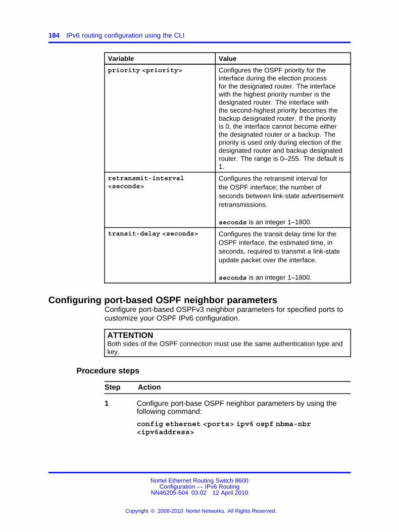
184 IPv6 routing configuration using the CLI
Variable Value
priority <priority> Configures the OSPF priority for theinterface during the election processfor the designated router. The interfacewith the highest priority number is thedesignated router. The interface withthe second-highest priority becomes thebackup designated router. If the priorityis 0, the interface cannot become eitherthe designated router or a backup. Thepriority is used only during election of thedesignated router and backup designatedrouter. The range is 0–255. The default is1.
retransmit-interval<seconds>
Configures the retransmit interval forthe OSPF interface; the number ofseconds between link-state advertisementretransmissions.
seconds is an integer 1–1800.
transit-delay <seconds> Configures the transit delay time for theOSPF interface, the estimated time, inseconds, required to transmit a link-stateupdate packet over the interface.
seconds is an integer 1–1800.
Configuring port-based OSPF neighbor parametersConfigure port-based OSPFv3 neighbor parameters for specified ports tocustomize your OSPF IPv6 configuration.
ATTENTIONBoth sides of the OSPF connection must use the same authentication type andkey.
Procedure steps
Step Action
1 Configure port-base OSPF neighbor parameters by using thefollowing command:
config ethernet <ports> ipv6 ospf nbma-nbr<ipv6address>
Nortel Ethernet Routing Switch 8600Configuration — IPv6 Routing
NN46205-504 03.02 12 April 2010
Copyright © 2008-2010 Nortel Networks. All Rights Reserved.
.

Configuring OSPF parameters for a VLAN 185
ATTENTIONYou must use an IPv6 link-local address as an NBMA neighbor.
--End--
Variable definitionsUse the data in the following table to use the config ethernet ipv6ospf nbma-nbr command.
Variable Value
create <priority> Creates a neighbor priority. The range is0–255. The default is 1.
delete Deletes an OSPF NBMA neighbor.
info Displays OSPF characteristics on the port.
ipv6address Specifies the IPv6 address of the neighbor asa string of 0–43.
ports Specifies the port or range of ports to configurein the format slot/port.
priority <priority> Configures the OSPF priority for the interfaceduring the election process for the designatedrouter. The interface with the highest prioritynumber is the designated router. The interfacewith the second-highest priority becomesthe backup designated router. If the priorityis 0, the interface cannot become either thedesignated router or a backup. The priorityis used only during election of the designatedrouter and backup designated router. Therange is 0–255. The default is 1.
Configuring OSPF parameters for a VLANConfigure OSPFv3 parameters for a specified VLAN to customize yourOSPF IPv6 configuration.
Procedure steps
Step Action
1 Configure OSPF parameters for a VLAN by using the followingcommand:
config vlan <vid> ipv6 ospf
--End--
Nortel Ethernet Routing Switch 8600Configuration — IPv6 Routing
NN46205-504 03.02 12 April 2010
Copyright © 2008-2010 Nortel Networks. All Rights Reserved.
.

186 IPv6 routing configuration using the CLI
Variable definitionsUse the data in the following table to use the config vlan ipv6 ospfcommand.
Variable Value
admin-status<enable|disable>
Configures the state (enabled or disabled) of the OSPFinterface.
create <area>[priority <value>] [metric <value>] [retransmit-interval <value>] [transit-delay<value> ] [hello-interval <value>] [dead-interval<value> ] [type<value> ]
Creates an OSPF interface.
• <area> is the area IP address (0.0.0.0 to255.255.255.255) {a.b.c.d}.
• priority <value> is the priority in the range0–255.
• metric <value> is the metric in the range0–65535.
• retransmit-interval <value> is theretransmit interval in the range 1–1800 seconds.
• transit-delay <value> is the transit delay inthe range 1–1800 seconds.
• hello-interval <value> is the hello interval inthe range 1–65535 seconds.
• dead-interval <value> is the dead interval inthe range 1–4095 seconds.
• type <st|nbma|p2p|p2mp> is the type ofinterface where 1 is ethernet, 2 is nbma, 3 is p2p, 4is lookback, and 5 is p2mp.
dead-interval<seconds>
Configures the OSPF dead interval for the interface.
seconds is the number of seconds the switch OSPFneighbors wait before determining that this OSPFrouter is down. The range is 1–4095. This value mustbe at least four times the hello interval value. Thedefault is 40.
delete Deletes an OSPF interface.
Nortel Ethernet Routing Switch 8600Configuration — IPv6 Routing
NN46205-504 03.02 12 April 2010
Copyright © 2008-2010 Nortel Networks. All Rights Reserved.
.

Configuring OSPF parameters for a VLAN 187
Variable Value
hello-interval<seconds>
Configures the OSPF hello interval for the interface.
seconds is the number of seconds between hellopackets sent on this interface. The range is 1–65535.The default is 10.
ATTENTIONWhen you change the hello interval values, you mustsave the configuration file and reboot the switch torestore the values and check for consistency.
info Displays OSPF characteristics on the VLAN.
metric <metric> Configures the OSPF metric for the interface.The switch advertises the metric in router linkadvertisements.
metric is the range 0–65535.
poll-interval<seconds>
Configures the polling interval for the OSPF interfacein seconds.
seconds is 0–2147483647.
priority<priority>
Configures the OSPF priority for the interfaceduring the election process for the designatedrouter. The interface with the highest prioritynumber is the designated router. The interface withthe second-highest priority becomes the backupdesignated router. If the priority is 0, the interfacecannot become either the designated router or abackup. The priority is used only during election of thedesignated router and backup designated router.
priority is in the range 0–255. The default is 1.
retransmit-interval <seconds>
Configures the retransmit interval for the OSPFinterface; the number of seconds between link-stateadvertisement retransmissions.
seconds is an integer from 1–1800.
Nortel Ethernet Routing Switch 8600Configuration — IPv6 Routing
NN46205-504 03.02 12 April 2010
Copyright © 2008-2010 Nortel Networks. All Rights Reserved.
.

188 IPv6 routing configuration using the CLI
Variable Value
transit-delay<seconds>
Configures the transit delay time for the OSPFinterface, the estimated time, in seconds, required totransmit a link-state update packet over the interface.
seconds is an integer from 1–1800.
vid Specifies a unique integer value in the range 1–4094that identifies the VLAN to configure.
Configuring OSPF neighbor parameters for a VLANConfigure port-based OSPFv3 neighbor parameters for a VLAN tocustomize your OSPF IPv6 configuration.
ATTENTIONBoth sides of the OSPF connection must use the same authentication type andkey.
Procedure steps
Step Action
1 Configure OSPF neighbor parameters for a VLAN by using thefollowing command:
config vlan <vid> ipv6 ospf nbma-nbr <ipv6address>
--End--
Variable definitionsUse the data in the following table to use the config vlan ipv6 ospfnbma-nbr command.
Variable Value
create <priority> Creates a neighbor priority.
priority is in the range 0–255. The default is 1.
delete Deletes an OSPF NBMA neighbor.
info Displays OSPF characteristics on the port.
ipv6address Specifies the IPv6 address of the neighbor as a stringof 0–43 characters.
Nortel Ethernet Routing Switch 8600Configuration — IPv6 Routing
NN46205-504 03.02 12 April 2010
Copyright © 2008-2010 Nortel Networks. All Rights Reserved.
.

Configuring OSPF neighbor parameters for a VLAN 189
Variable Value
priority<priority>
Configures the OSPF priority for the interfaceduring the election process for the designatedrouter. The interface with the highest prioritynumber is the designated router. The interface withthe second-highest priority becomes the backupdesignated router. If the priority is 0, the interfacecannot become either the designated router or abackup. The priority is used only during election of thedesignated router and backup designated router.
priority is in the range 0–255. The default is 1.
vid Specifies a unique integer value in the range 1–4094that identifies the VLAN to configure.
Nortel Ethernet Routing Switch 8600Configuration — IPv6 Routing
NN46205-504 03.02 12 April 2010
Copyright © 2008-2010 Nortel Networks. All Rights Reserved.
.

190 IPv6 routing configuration using the CLI
Nortel Ethernet Routing Switch 8600Configuration — IPv6 Routing
NN46205-504 03.02 12 April 2010
Copyright © 2008-2010 Nortel Networks. All Rights Reserved.
.

191.
IPv6 routing configuration using theNNCLI
This chapter contains procedures to configure IPv6 static routes and theOpen Shortest Path First version 3 (OSPFv3) protocol.
IPv6 routing configuration navigation• “Job aid: Roadmap of IPv6 static route and OSPFv3 NNCLI
commands” (page 191)
• “Configuring IPv6 static routes” (page 193)
• “Configuring OSPF global parameters” (page 195)
• “Configuring OSPF areas” (page 196)
• “Configuring OSPF area ranges” (page 197)
• “Configuring OSPF area virtual interfaces” (page 198)
• “Configuring an OSPF interface” (page 200)
• “Configuring OSPF direct redistribution” (page 203)
• “Configuring OSPF static redistribution” (page 203)
• “Configuring port-based OSPF neighbor parameters” (page 204)
• “Configuring OSPF parameters for a VLAN” (page 205)
• “Configuring OSPF neighbor parameters for a VLAN” (page 208)
Job aid: Roadmap of IPv6 static route and OSPFv3 NNCLIcommands
The following table lists the commands and parameters that you use toperform the procedures in this section.
Nortel Ethernet Routing Switch 8600Configuration — IPv6 Routing
NN46205-504 03.02 12 April 2010
Copyright © 2008-2010 Nortel Networks. All Rights Reserved.
.

192 IPv6 routing configuration using the NNCLI
Table 11Job aid: Roadmap of IPv6 static route and OSPFv3 NNCLI commands
Command Parameter
Global Configuration mode
enable [next-hop <Ipv6 address/prefix>][port <slot/port>] [tunnel <tunnel-id>][vlan <vlan id>]
cost <1-65535>
ipv6 route <Ipv6 address/prefix>
preference <1-255>
router ospf ipv6-enable
Interface Configuration mode
area <A.B.C.D> enable
cost <metric>
dead-interval <seconds>
hello-interval <seconds>
poll-interval <seconds>
priority <value>
retransmit-interval <seconds>
ipv6 ospf
transmit-delay <seconds>
ipv6 ospf nbma-nbr <Ipv6address/prefix-len> priority <priority>
OSPF Router Configuration mode
as-boundary-router enableipv6
router-id <A.B.C.D>
default-cost <cost>
import <value>
import-summaries enable
translator-role <value>
ipv6 area <A.B.C.D>
type <nssa|stub>
inter-area-prefix-link advertise-mode<advertise|not-advertise> advertise-mode <advertise|not-advertise>advertise-metric <0–65535>
ipv6 ipv6 area range <Ipv6address/prefix> <A.B.C.D>
nssa-extlink advertise-metric<0-65535>
Nortel Ethernet Routing Switch 8600Configuration — IPv6 Routing
NN46205-504 03.02 12 April 2010
Copyright © 2008-2010 Nortel Networks. All Rights Reserved.
.

Configuring IPv6 static routes 193
Table 11Job aid: Roadmap of IPv6 static route and OSPFv3 NNCLI commands (cont’d.)
Command Parameter
dead-interval <seconds>
hello-interval <seconds>
retransmit-interval <seconds>
ipv6 area virtual-link <area IPaddress> <virtual link IP address>
transit-delay <seconds>
direct enableipv6 redistribute
static enable
Configuring IPv6 static routesConfigure IPv6 static routes to change static routes directly with the IPv6static routing table manager. Create a new static route or modify existingstatic route parameters.
Prerequisites
• You must log on to the Global Configuration mode in the NNCLI.
Procedure steps
Step Action
1 Create the static route by using the following command:
ipv6 route <Ipv6 address/prefix> enable [next-hop<Ipv6 address/prefix>] [port <slot/port>] [tunnel<tunnel-id>] [vlan <vlan id>]
2 Assign the cost by using the following command:
ipv6 route <Ipv6 address/prefix> cost <1-65535>
3 Configure the preference by using the following command:
ipv6 route <Ipv6 address/prefix> preference <1-255>
--End--
Variable definitionsUse the data in the following table to use the ipv6 route command.
Variable Value
cost <1-65535> cost <value> is the metric of the route in therange of 1–65535.
Nortel Ethernet Routing Switch 8600Configuration — IPv6 Routing
NN46205-504 03.02 12 April 2010
Copyright © 2008-2010 Nortel Networks. All Rights Reserved.
.

194 IPv6 routing configuration using the NNCLI
Variable Value
enable [next-hop <Ipv6address/prefix>] [port<slot/port>] [tunnel<tunnel-id>] [vlan<vlan id>]
Adds a static or default route to the switch.
• ipv6address/prefix is the IP addressand prefix for the route destination as astring of 0–46 characters.
• next-hop <value> is the IP address ofthe next-hop router—the next router atwhich packets must arrive on this route.The string length is 0–46 characters.When creating a black hole static route,set this field to 255.255.255.255 as the IPaddress of the router through which thespecified route is accessible.
• port <value> is the slot/port number.
• vlan <value> is the VLAN ID in the rangeof 1–4094.
• tunnel <value> configures the tunnel IDin the range of 1-5000.
preference <preference><ipv6addr-prefix>[next-hop <value> ][port <value> ] [vlan<value> ] [tunnel<value> ]
Modifies static route preference.
• preference configures the routepreference in the range of 1–255. Thedefault value is 0.
• ipv6addr-prefix is the IP address andprefix for the route destination as a string0–46 characters.
• next-hop <value> is the IP address ofthe next-hop router—the next router atwhich packets must arrive on this route.The string length is 0–46 characters.
• port <value> is the slot/port number.
• vlan <value> is the VLAN ID in the rangeof 1–4094.
• tunnel <value> is the tunnel ID valuein the range of 1-5000. When you select atunnel, you must provide the VLAN, port,and next hop. You must configure an IPv6tunnel before you enter this value.
ATTENTIONA black hole route is a route with an invalidnext hop, so the switch drops data packetsdestined to this network. When you specify aroute preference, be sure that you configurethe preference value appropriately so that
Nortel Ethernet Routing Switch 8600Configuration — IPv6 Routing
NN46205-504 03.02 12 April 2010
Copyright © 2008-2010 Nortel Networks. All Rights Reserved.
.

Configuring OSPF global parameters 195
Variable Value
when you use the black-hole route, it iselected as the best route.
Configuring OSPF global parametersConfigure Open Shortest Path First (OSPF) global parameters to affectOSPF routing on the entire switch. Routers use the OSPF protocol toexchange network topology information, providing each router with a mapof the network.
Prerequisites
• You must log on to the Global Configuration mode in the NNCLI.
Procedure steps
Step Action
1 Enable OSPF for IPv6 by using the following command:
router ospf ipv6-enable
2 Log on to the OSPF Router configuration mode by using thefollowing command:
router ospf
3 Enable the OSPF autonomous system boundary router by usingthe following command:
ipv6 as-boundary-router enable
4 Configure the OSPF router ID by using the following command:
ipv6 router-id <A.B.C.D>
--End--
Variable definitionsUse the data in the following table to use the ipv6 router-id command.
Variable Value
router-id <A.B.C.D> Configures the OSPF router ID IPv6 address.
Nortel Ethernet Routing Switch 8600Configuration — IPv6 Routing
NN46205-504 03.02 12 April 2010
Copyright © 2008-2010 Nortel Networks. All Rights Reserved.
.

196 IPv6 routing configuration using the NNCLI
Configuring OSPF areasOSPF supports hierarchical routing by dividing the Autonomous Systeminto different areas. When two or more areas exist, the backbone area(area 0.0.0.0) must always be present.
You can use any value for the OSPF area name (for example, 1.1.1.1 or200.200.200.200).
Prerequisites
• You must log on to the OSPF Router Configuration mode in theNNCLI.
Procedure steps
Step Action
1 Create and configure an OSPF area by using the followingcommand:
ipv6 area <A.B.C.D> default-cost <cost> import <value>[import-summaries enable] translator-role <value> type<nssa|stub>
--End--
Variable definitionsUse the data in the following table to use the ipv6 area command.
Variable Value
default-cost <cost> Stub default metric for this stub area.
cost is the range from 0 to 16777215. This isthe metric value applied at the indicated typeof service.
To configure this option to the default value,use the default operator with the command.The default value is 10.
Nortel Ethernet Routing Switch 8600Configuration — IPv6 Routing
NN46205-504 03.02 12 April 2010
Copyright © 2008-2010 Nortel Networks. All Rights Reserved.
.

Configuring OSPF area ranges 197
Variable Value
import <value> Configures the area support for importingadvertisements. The options are:• external—Stub and nssa are both false
• noexternal—Configure the area as stubarea
• nssa—Configure the area as nssa
To configure this option to the default value,use the default operator with the command.The default value is external.
import-summaries enable Configures the area support for importingsummary advertisements into a stub area. Usethis entry only for a stub area. To configurethis option to the default value, use thedefault operator with the command.The default value is true.
translator-role <value> Indicates an NSSA Border router ability toperform translation of type-7 LSAs into type-5LSAs.Valid values are 1 (always) or 2 (candidate).Default value is 1 (always).
type <nssa|stub> Configures the type of area. An NSSAprevents flooding of normal routeadvertisements into the area by replacingthem with a default route. A stub area usesonly one exit point (router interface) from thearea.By default, the area is neither a stub area oran NSSA.
Configuring OSPF area rangesConfigure an area address range on the OSPF router to reduce thenumber of ABR advertisements into other OSPF areas. An area addressrange is an implied contiguous range of area network addresses for whichthe ABR advertises a single summary route.
Configure the area by using one of the two LSA types: inter-area-prefix-link or nssa-extlink.
You can use any value for the OSPF area name (for example, 1.1.1.1 or200.200.200.200).
Nortel Ethernet Routing Switch 8600Configuration — IPv6 Routing
NN46205-504 03.02 12 April 2010
Copyright © 2008-2010 Nortel Networks. All Rights Reserved.
.

198 IPv6 routing configuration using the NNCLI
Prerequisites
• You must log on to the OSPF Router Configuration mode in theNNCLI.
Procedure steps
Step Action
1 Configure an OSPF area range by using the following command:
ipv6 area range <A.B.C.D> <Ipv6 address/prefix><inter-area-prefix-link|nssa-extlink> advertise-mode<advertise|not-advertise>] advertise-metric <0–65535>
--End--
Variable definitionsUse the data in the following table to use the ipv6 area rangecommand.
Variable Value
A.B.C.D Specifies the IP address of the area.
advertise-metric<0–65535>
Specifies the advertise metric value and LSAtype.
The default value is 0.
advertise-mode <advertise|no-advertise>
Specifies the area range advertise mode asadvertise or no-advertise.The default value is advertise.
ipv6addrress/prefix Configures the IPv6 address range of anOSPF area. The string length is 0–255characters.
Configuring OSPF area virtual interfacesIf a remote OSPF ABR uses no connection to the backbone area butneeds to be part of the same routing domain (AS) in which the switchresides, configure an OSPF virtual interface to the ABR.
You can use any value for the OSPF area name (for example, 1.1.1.1 or200.200.200.200).
Nortel Ethernet Routing Switch 8600Configuration — IPv6 Routing
NN46205-504 03.02 12 April 2010
Copyright © 2008-2010 Nortel Networks. All Rights Reserved.
.

Configuring OSPF area virtual interfaces 199
ATTENTIONOSPF behavior is modified according to OSPF standards so that OSPF routescannot be learned through an area border router (ABR) unless the routerconnects to the backbone or through a virtual link.
Prerequisites
• You must log on to the OSPF Router Configuration mode in theNNCLI.
Procedure steps
Step Action
1 Configure an OSPF area virtual interface by using the followingcommand:
ipv6 area virtual-link <area IP address> <virtual linkIP address> dead-interval <seconds> hello-interval<seconds> retransmit-interval <seconds> transit-delay<seconds>
--End--
Variable definitionsUse the data in the following table to use the ipv6 area virtual-linkcommand.
Variable Value
dead-interval <seconds> Specifies the dead interval, in seconds, asa range 1–4 095. To configure this optionto the default value, use the defaultoperator with the command.The default value is 60.
hello-interval <seconds> Specifies the Hello interval, in seconds,sent between switches for a virtualinterface in an OSPF area. The range is1–65535. To configure this option to thedefault value, use the default operatorwith the command.The default value is 10.
Nortel Ethernet Routing Switch 8600Configuration — IPv6 Routing
NN46205-504 03.02 12 April 2010
Copyright © 2008-2010 Nortel Networks. All Rights Reserved.
.

200 IPv6 routing configuration using the NNCLI
Variable Value
retransmit-interval<seconds>
Specifies the retransmit interval, inseconds, sent between switches for avirtual interface in an OSPF area. Therange is 1–1800. To configure this optionto the default value, use the defaultoperator with the command.The default value is 5.
transit-delay <seconds> Specifies the transit delay interval, inseconds, sent between switches for avirtual interface in an OSPF area. Therange is 1–1800. To configure this optionto the default value, use the defaultoperator with the command.The default value is 1.
Configuring an OSPF interfaceConfigure an OSPF interface for designated router (DR) and backupdesignated router (BDR) election to reduce the amount of routing traffic.
Prerequisites
• Before you can configure OSPF parameters on an interface, you mustfirst configure IP on the interface.
• You must log on to the Interface Configuration mode in the NNCLI.
Procedure steps
Step Action
1 Associate the interface with an OSPF area with the followingcommand:
ipv6 ospf area <A.B.C.D>
2 Enable OSPF on the interface by using the following command:
ipv6 ospf enable
3 Configure the OSPF area by using the following command:
ipv6 ospf area <A.B.C.D> cost <metric> [dead-interval<seconds>] [hello-interval <seconds>][network<value>][priority <value>] [retransmit-interval<seconds>] [transmit-delay <seconds>]
4 Enable an OSPF area on an interface by using the followingcommand:
ipv6 ospf area <A.B.C.D>
Nortel Ethernet Routing Switch 8600Configuration — IPv6 Routing
NN46205-504 03.02 12 April 2010
Copyright © 2008-2010 Nortel Networks. All Rights Reserved.
.

Configuring an OSPF interface 201
5 Configure the interface by using the following command:
ipv6 ospf cost <metric> [priority <value>]
--End--
Variable definitionsUse the data in the following table to use the ipv6 ospf command.
Variable Value
area <A.B.C.D> Specifies the area IP address (0.0.0.0 to255.255.255.255) {a.b.c.d}.
cost <metric> Configures the OSPF metric for the interface.The switch advertises the metric in router linkadvertisements.
metric is the range 0–65535.
To configure this option to the default value,use the default operator with the command.The default value is 1.
dead-interval <seconds> Configures the OSPF dead interval for theinterface.
seconds is the number of seconds the switchOSPF neighbors wait before determining thatthis OSPF router is down. The range is from1-4095. This value must be at least four timesthe Hello interval value. The default is 40.
To configure this option to the default value,use the default operator with the command.
hello-interval<seconds>
Configures the OSPF hello interval for theinterface.
seconds is the number of seconds betweenhello packets sent on this interface. The rangeis 1–65535. The default is 10.
ATTENTIONWhen you change the hello interval values,you must save the configuration file and
Nortel Ethernet Routing Switch 8600Configuration — IPv6 Routing
NN46205-504 03.02 12 April 2010
Copyright © 2008-2010 Nortel Networks. All Rights Reserved.
.
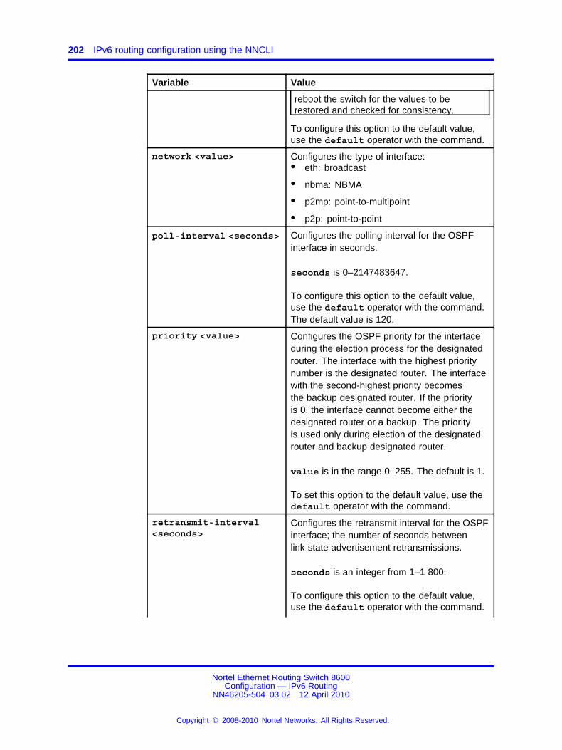
202 IPv6 routing configuration using the NNCLI
Variable Value
reboot the switch for the values to berestored and checked for consistency.
To configure this option to the default value,use the default operator with the command.
network <value> Configures the type of interface:• eth: broadcast
• nbma: NBMA
• p2mp: point-to-multipoint
• p2p: point-to-point
poll-interval <seconds> Configures the polling interval for the OSPFinterface in seconds.
seconds is 0–2147483647.
To configure this option to the default value,use the default operator with the command.The default value is 120.
priority <value> Configures the OSPF priority for the interfaceduring the election process for the designatedrouter. The interface with the highest prioritynumber is the designated router. The interfacewith the second-highest priority becomesthe backup designated router. If the priorityis 0, the interface cannot become either thedesignated router or a backup. The priorityis used only during election of the designatedrouter and backup designated router.
value is in the range 0–255. The default is 1.
To set this option to the default value, use thedefault operator with the command.
retransmit-interval<seconds>
Configures the retransmit interval for the OSPFinterface; the number of seconds betweenlink-state advertisement retransmissions.
seconds is an integer from 1–1 800.
To configure this option to the default value,use the default operator with the command.
Nortel Ethernet Routing Switch 8600Configuration — IPv6 Routing
NN46205-504 03.02 12 April 2010
Copyright © 2008-2010 Nortel Networks. All Rights Reserved.
.

Configuring OSPF static redistribution 203
Variable Value
The default value is 5.
transit-delay <seconds> Configures the transit delay time for the OSPFinterface, the estimated time in seconds ittakes to transmit a link-state update packetover the interface.
seconds is an integer from 1–1 800.
To configure this option to the default value,use the default operator with the command.The default value is 1.
Configuring OSPF direct redistributionEnable or disable direct redistribution to redistribute IPv6 direct routes intoan OSPFv3 routing domain.
Prerequisites
• You must log on to the OSPF Router Configuration mode in theNNCLI.
Procedure steps
Step Action
1 Configure OSPF direct redistribution by using the followingcommand:
ipv6 redistribute direct enable
--End--
Configuring OSPF static redistributionEnable or disable static redistribution to redistribute IPv6 static routes intoan OSPFv3 routing domain.
Prerequisites
• You must log on to the OSPF Router Configuration mode in theNNCLI.
Nortel Ethernet Routing Switch 8600Configuration — IPv6 Routing
NN46205-504 03.02 12 April 2010
Copyright © 2008-2010 Nortel Networks. All Rights Reserved.
.

204 IPv6 routing configuration using the NNCLI
Procedure steps
Step Action
1 Configure OSPF static redistribution by using the followingcommand:
ipv6 redistribute static enable
--End--
Configuring port-based OSPF neighbor parametersConfigure port-based OSPFv3 neighbor parameters for specified ports tocustomize your OSPF IPv6 configuration.
ATTENTIONBoth sides of the OSPF connection must use the same authentication type andkey.
Prerequisites
• You must log on to the Interface Configuration mode in the NNCLI.
Procedure steps
Step Action
1 Configure port-based OSPF neighbor parameters by using thefollowing command:
ipv6 ospf nbma-nbr <Ipv6address/prefix-len> priority<priority>
ATTENTIONYou must use an IPv6 link-local address as an NBMA neighbor.
--End--
Variable definitionsUse the data in the following table to use the ipv6 ospf nbma-nbrcommand.
Nortel Ethernet Routing Switch 8600Configuration — IPv6 Routing
NN46205-504 03.02 12 April 2010
Copyright © 2008-2010 Nortel Networks. All Rights Reserved.
.

Configuring OSPF parameters for a VLAN 205
Variable Value
Ipv6address/prefix-len Specifies the IPv6 address of the neighbor asa string of 0–43 characters.
priority <priority> Configures the OSPF priority for the interfaceduring the election process for the designatedrouter. The interface with the highest prioritynumber is the designated router. The interfacewith the second-highest priority becomesthe backup designated router. If the priorityis 0, the interface cannot become either thedesignated router or a backup. The priorityis used only during election of the designatedrouter and backup designated router. Therange is 0 to 255. The default is 1. Toconfigure this option to the default value, usethe default operator with the command.
Configuring OSPF parameters for a VLANConfigure OSPFv3 parameters for a specified VLAN to customize yourOSPF IPv6 configuration.
Prerequisites
• You must log on to the VLAN Interface Configuration mode in theNNCLI.
Procedure steps
Step Action
1 Associate the OSPF area with an interface by using the followingcommand:
ipv6 ospf area <A.B.C.D>
2 Enable OSPF on the interface with the following command:
ipv6 ospf enable
3 Configure the area by using the following command:
ipv6 ospf area <A.B.C.D> cost <metric> [dead-interval<seconds>] [hello-interval <seconds>][network<value>][priority <value>] [retransmit-interval<seconds>] [transmit-delay <seconds>]
4 Configure the interface by using the following command:
Nortel Ethernet Routing Switch 8600Configuration — IPv6 Routing
NN46205-504 03.02 12 April 2010
Copyright © 2008-2010 Nortel Networks. All Rights Reserved.
.

206 IPv6 routing configuration using the NNCLI
ipv6 ospf cost <metric> [priority <value>]
--End--
Variable definitionsUse the data in the following table to use the ipv6 ospf command.
Variable Value
area <A.B.C.D> Specifies the area IP address (0.0.0.0 to255.255.255.255) {a.b.c.d}.
cost <metric> Configures the OSPF metric for the interface.The switch advertises the metric in router linkadvertisements.
metric is the range 0–65535.
To configure this option to the default value,use the default operator with the command.The default value is 1.
dead-interval <seconds> Configures the OSPF dead interval for theinterface.
seconds is the number of seconds the switchOSPF neighbors wait before determining thatthis OSPF router is down. The range is from1-4095. This value must be at least four timesthe Hello interval value. The default is 40.
To configure this option to the default value,use the default operator with the command.
hello-interval<seconds>
Configures the OSPF hello interval for theinterface.
seconds is the number of seconds betweenhello packets sent on this interface. The rangeis 1–65 535. The default is 10.
ATTENTIONWhen you change the hello interval values,you must save the configuration file andrestart the switch to restore the values andcheck for consistency.
To configure this option to the default value,use the default operator with the command.
Nortel Ethernet Routing Switch 8600Configuration — IPv6 Routing
NN46205-504 03.02 12 April 2010
Copyright © 2008-2010 Nortel Networks. All Rights Reserved.
.
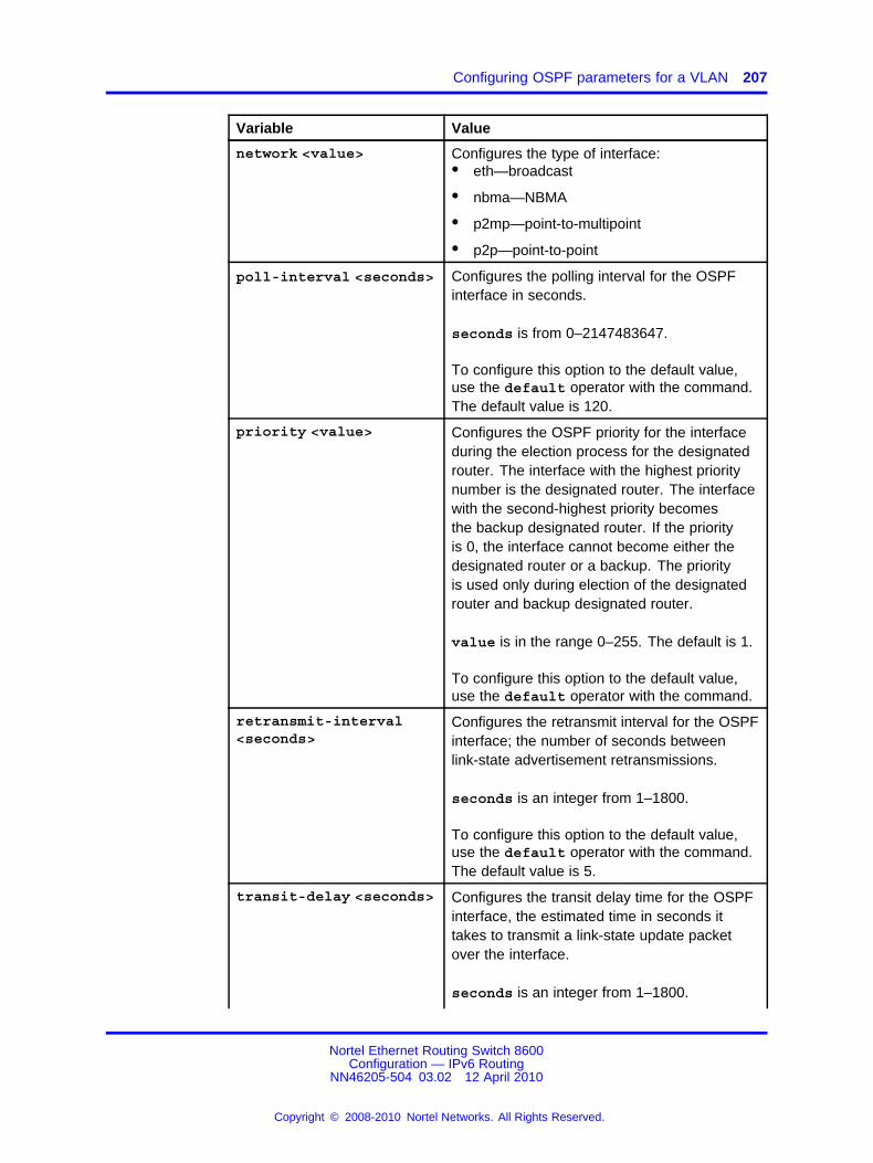
Configuring OSPF parameters for a VLAN 207
Variable Value
network <value> Configures the type of interface:• eth—broadcast
• nbma—NBMA
• p2mp—point-to-multipoint
• p2p—point-to-point
poll-interval <seconds> Configures the polling interval for the OSPFinterface in seconds.
seconds is from 0–2147483647.
To configure this option to the default value,use the default operator with the command.The default value is 120.
priority <value> Configures the OSPF priority for the interfaceduring the election process for the designatedrouter. The interface with the highest prioritynumber is the designated router. The interfacewith the second-highest priority becomesthe backup designated router. If the priorityis 0, the interface cannot become either thedesignated router or a backup. The priorityis used only during election of the designatedrouter and backup designated router.
value is in the range 0–255. The default is 1.
To configure this option to the default value,use the default operator with the command.
retransmit-interval<seconds>
Configures the retransmit interval for the OSPFinterface; the number of seconds betweenlink-state advertisement retransmissions.
seconds is an integer from 1–1800.
To configure this option to the default value,use the default operator with the command.The default value is 5.
transit-delay <seconds> Configures the transit delay time for the OSPFinterface, the estimated time in seconds ittakes to transmit a link-state update packetover the interface.
seconds is an integer from 1–1800.
Nortel Ethernet Routing Switch 8600Configuration — IPv6 Routing
NN46205-504 03.02 12 April 2010
Copyright © 2008-2010 Nortel Networks. All Rights Reserved.
.

208 IPv6 routing configuration using the NNCLI
Variable Value
To configure this option to the default value,use the default operator with the command.The default value is 1.
Configuring OSPF neighbor parameters for a VLANConfigure port-based OSPFv3 neighbor parameters for a VLAN tocustomize your OSPF IPv6 configuration.
ATTENTIONBoth sides of the OSPF connection must use the same authentication type andkey.
Prerequisites
• You must log on to the VLAN Interface Configuration mode in theNNCLI.
Procedure steps
Step Action
1 Configure OSPF neighbor parameters for a VLAN by using thefollowing command:
ipv6 ospf nbma-nbr <Ipv6address/prefix-len> priority<priority>
--End--
Variable definitionsUse the data in the following table to use the ipv6 ospf nbma-nbrcommand.
Variable Value
Ipv6address/prefix-len Specifies the IPv6 address of the neighbor asa string of 0–43.
priority <priority> Configures the OSPF priority for the interfaceduring the election process for the designatedrouter. The interface with the highest prioritynumber is the designated router. The interfacewith the second-highest priority becomesthe backup designated router. If the priorityis 0, the interface cannot become either the
Nortel Ethernet Routing Switch 8600Configuration — IPv6 Routing
NN46205-504 03.02 12 April 2010
Copyright © 2008-2010 Nortel Networks. All Rights Reserved.
.

Configuring OSPF neighbor parameters for a VLAN 209
Variable Value
designated router or a backup. The priorityis used only during election of the designatedrouter and backup designated router. Therange is 0–255. The default is 1. To configurethis option to the default value, use thedefault operator with the command.
Nortel Ethernet Routing Switch 8600Configuration — IPv6 Routing
NN46205-504 03.02 12 April 2010
Copyright © 2008-2010 Nortel Networks. All Rights Reserved.
.

210 IPv6 routing configuration using the NNCLI
Nortel Ethernet Routing Switch 8600Configuration — IPv6 Routing
NN46205-504 03.02 12 April 2010
Copyright © 2008-2010 Nortel Networks. All Rights Reserved.
.

211.
IPv6 DHCP Relay configuration usingEnterprise Device Manager
Use the Forward Path tab to configure the DHCP Relay forward path, anduse the Interface tab to configure the related parameters (for example,max hops and remote ID).
DHCP configuration navigation• “Configuring the DHCP relay forwarding path” (page 211)
• “Configuring DHCP relay interface parameters” (page 212)
• “Viewing DHCP Relay statistics” (page 213)
Configuring the DHCP relay forwarding pathConfigure forwarding policies to indicate the relay agent and the DHCPserver to which packets are forwarded.
Procedure steps
Step Action
1 In the navigation tree, open the following folders: Configuration,IPv6.
2 Double-click DHCP Relay.
3 Click the Forward Path tab.
4 Click Insert.
5 In the AgentAddr box, type the agent address.
6 In the ServerAddr box, type the server address.
7 Click Enabled to enable DHCP relay. You can enable or disableeach agent server forwarding path. The default is enabled.
Nortel Ethernet Routing Switch 8600Configuration — IPv6 Routing
NN46205-504 03.02 12 April 2010
Copyright © 2008-2010 Nortel Networks. All Rights Reserved.
.

212 IPv6 DHCP Relay configuration using Enterprise Device Manager
8 Click Insert.
--End--
Variable definitionsUse the data in the following table to configure the DHCP Relay forwardpath.
Variable Value
AgentAddr The IP address of the input interface (agent) on which theDHCP request packets are received for forwarding. Thisaddress is the IP address of either a brouter port or a VLAN forwhich forwarding is enabled.
ServerAddr This parameter is the IP address of the DHCP server. Therequest is unicast to the server address.
Enable Enables DHCP relay on the routing switch.
Configuring DHCP relay interface parametersConfigure the DHCP relay behavior on the interface.
Procedure steps
Step Action
1 In the navigation tree, open the following folders: Configuration,IPv6.
2 Double-click DHCP Relay.
3 In the Interface tab, click Insert.
4 Enter the appropriate values.
5 Click Apply.
--End--
Variable definitionsUse the data in the following table to configure the DCHP Relay interfaceparameters.
Variable Value
IfIndex A read-only value indicating the unique value to identify anIPv6 interface. For the brouter port, it is the ifindex of theport and, in the case of the VLAN, it is the ifindex of theVLAN.
Nortel Ethernet Routing Switch 8600Configuration — IPv6 Routing
NN46205-504 03.02 12 April 2010
Copyright © 2008-2010 Nortel Networks. All Rights Reserved.
.

Viewing DHCP Relay statistics 213
Variable Value
MaxHop Specifies the maximum number of hops a DHCP packetcan take from the DHCP client to the DHCP server.
RemoteIdEnabled Enables or disables remote ID.
DhcpEnabled Specifies whether DHCP is enabled or disabled on theinterface.
Viewing DHCP Relay statisticsView DHCP Relay statistics to monitor network performance.
Procedure steps
Step Action
1 In the navigation tree, open the following folders: Configuration,IPv6.
2 Double-click DHCP Relay.
3 In the Interface tab, select an interface and click Statistics.
--End--
Variable definitionsUse the data in the following table to use the DHCP Relay Statistics tab.
Variable Value
NumRequests The count of request messages.
NumReplies The count of reply messages.
Nortel Ethernet Routing Switch 8600Configuration — IPv6 Routing
NN46205-504 03.02 12 April 2010
Copyright © 2008-2010 Nortel Networks. All Rights Reserved.
.

214 IPv6 DHCP Relay configuration using Enterprise Device Manager
Nortel Ethernet Routing Switch 8600Configuration — IPv6 Routing
NN46205-504 03.02 12 April 2010
Copyright © 2008-2010 Nortel Networks. All Rights Reserved.
.

215.
IPv6 DHCP Relay configuration usingthe CLI
Dynamic Host Configuration Protocol (DHCP) provides host configurationinformation to the workstations dynamically. Use the DHCP relaycommands to set DHCP relay behavior on a port or on a VLAN.
This section describes the CLI commands for IPv6 DHCP Relayconfiguration functions in the Ethernet Routing Switch 8600.
To configure DHCP Relay, you can use the config ipv6 dhcp-relaycommand, which allows you to specify the IP address of the port or VLANto use as a relay agent, or use the config {vlan <vid> | ethernet<ports>} ipv6 dhcp-relay command to explicitly specify the port orVLAN to use as the relay agent.
IPv6 DHCP relay configuration navigation• “Job aid: Roadmap of IPv6 DHCP Relay CLI commands” (page 215)
• “Configuring an IPv6 DHCP relay interface” (page 216)
• “Configuring IPv6 DHCP relay on a port or VLAN” (page 218)
• “Showing IPv6 DHCP relay information” (page 219)
• “Showing IPv6 DHCP relay information for a port or VLAN” (page 220)
Job aid: Roadmap of IPv6 DHCP Relay CLI commandsThe following table lists the IPv6 DHCP Relay commands and theirparameters that you use to complete the procedures in this section.
Table 12IPv6 DHCP Relay configuration commands
Command Parameter
config ipv6 dhcp-relay info
Nortel Ethernet Routing Switch 8600Configuration — IPv6 Routing
NN46205-504 03.02 12 April 2010
Copyright © 2008-2010 Nortel Networks. All Rights Reserved.
.
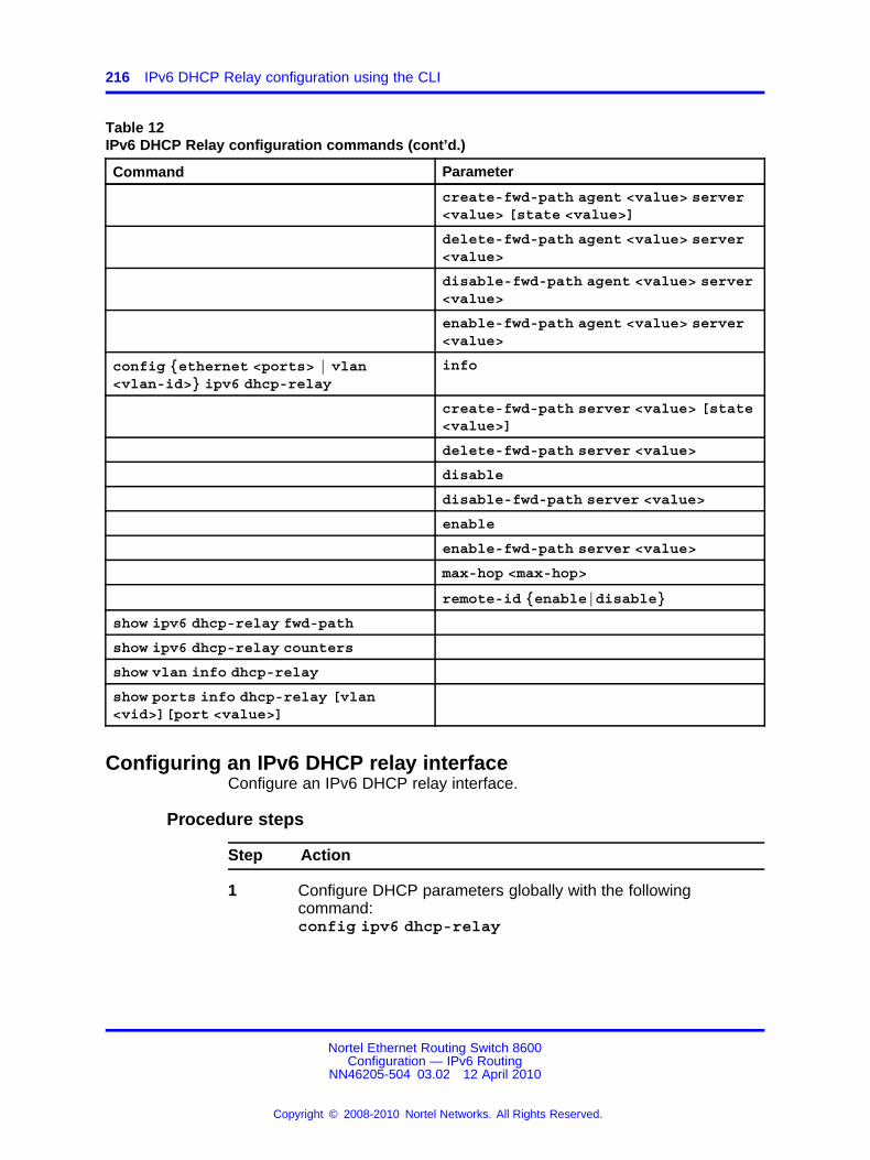
216 IPv6 DHCP Relay configuration using the CLI
Table 12IPv6 DHCP Relay configuration commands (cont’d.)
Command Parameter
create-fwd-path agent <value> server<value> [state <value>]
delete-fwd-path agent <value> server<value>
disable-fwd-path agent <value> server<value>
enable-fwd-path agent <value> server<value>
config {ethernet <ports> | vlan<vlan-id>} ipv6 dhcp-relay
info
create-fwd-path server <value> [state<value>]
delete-fwd-path server <value>
disable
disable-fwd-path server <value>
enable
enable-fwd-path server <value>
max-hop <max-hop>
remote-id {enable|disable}
show ipv6 dhcp-relay fwd-path
show ipv6 dhcp-relay counters
show vlan info dhcp-relay
show ports info dhcp-relay [vlan<vid>][port <value>]
Configuring an IPv6 DHCP relay interfaceConfigure an IPv6 DHCP relay interface.
Procedure steps
Step Action
1 Configure DHCP parameters globally with the followingcommand:config ipv6 dhcp-relay
Nortel Ethernet Routing Switch 8600Configuration — IPv6 Routing
NN46205-504 03.02 12 April 2010
Copyright © 2008-2010 Nortel Networks. All Rights Reserved.
.

Configuring an IPv6 DHCP relay interface 217
2 Confirm your configuration with the following command:config ipv6 dhcp-relay info
--End--
Variable definitionsUse the data in the following table to use the following commands:
• config ipv6 dhcp-relay
Variable Value
create-fwd-path agent <value>server <value> [state <value>]
Configures the forwarding path from the client to theserver.
• agent <value> is the IPv6 address configuredon an interface (a locally configured IPv6address) that must be configured to forward orrelay DHCP messages.
• server <value> is the IPv6 address of theDHCP server in the network.
• state <value> enables or disables theforwarding path.
delete-fwd-path agent <value>server <value>
Deletes the forwarding path from the client to theserver.
• agent <value> is the IPv6 address configuredon an interface (a locally configured IPv6address).
• server <value> is the IPv6 address of theDHCP server in the network.
disable-fwd-path agent <value>server <value>
Disables DHCP relaying on the path from the IPaddress to the server. This is the default.
• agent <value> is the IPv6 address configuredon an interface (a locally configured IPv6address).
• server <value> is the IPv6 address of theDHCP server in the network.
Nortel Ethernet Routing Switch 8600Configuration — IPv6 Routing
NN46205-504 03.02 12 April 2010
Copyright © 2008-2010 Nortel Networks. All Rights Reserved.
.

218 IPv6 DHCP Relay configuration using the CLI
Variable Value
enable-fwd-path agent <value>server <value>
Enables DHCP relaying on the path from the IPv6address to the server.
• agent <value> is the IPv6 address configuredon an interface (a locally configured IPv6address).
• server <value> is the IPv6 address of theDHCP server in the network.
info Displays the current DHCP global configuration onthe switch.
Configuring IPv6 DHCP relay on a port or VLANYou can configure DHCP parameters on specific ports or VLANs.
Procedure steps
Step Action
1 Configure DHCP parameters on a specified port or VLAN byusing the following command:config {vlan <vid> | ethernet <ports>} ipv6dhcp-relay
2 Confirm your configuration by using the following command:config {vlan| ethernet} ipv6 dhcp-relay info
--End--
Variable definitionsUse the data in the following table to use the config {vlan <vid> |ethernet <ports>} ipv6 dhcp-relay command.
Variable Value
create-fwd-path server<value> [state <value>]
Configures the forwarding path from the client (port orVLAN) to the server.
• <value> is the IPv6 address of the DHCP server inthe network.
• state <value> enables or disables the forwardingpath.
delete-fwd-path server<value>
Deletes the forwarding path to the specified server.
• value is the IPv6 address in the format X:X::X:X.
Nortel Ethernet Routing Switch 8600Configuration — IPv6 Routing
NN46205-504 03.02 12 April 2010
Copyright © 2008-2010 Nortel Networks. All Rights Reserved.
.

Showing IPv6 DHCP relay information 219
Variable Value
disable Disables DHCP relay on the port. This is the default state.
disable-fwd-path server<value>
Disables the forwarding path to the specified server.
• value is the IPv6 address in the format X:X::X:X.
enable Enables DHCP relay on the port.
enable-fwd-path server<value>
Enables the forwarding path server to the specified server.
• value is the IPv6 address in the form X:X::X:X.
info Displays the current DHCP configuration on the port.
max-hop <max-hop> Sets the maximum number of hops before a DHCP packetis discarded (1 to 32). The default is 32.
remote-id {enable | disable} Enables or disables remote ID.
Showing IPv6 DHCP relay informationDisplay DHCP relay information to show forward paths and counters.
Procedure steps
Step Action
1 Display information about the DHCP relay forward path with thefollowing command:show ipv6 dhcp-relay fwd-path
2 Display information about DHCP relay counters by using thefollowing command:show ipv6 dhcp-relay counters
--End--
Job aidThe following table shows the field descriptions for the show ipv6dhcp-relay counters command.
Table 13show ip dhcp-relay command
Parameter Description
INTERFACE Indicates the interface IPv6 address.
REQUEST Indicates the total number of DHCP requests received onthis interface.
REPLIES Indicates the total number of DHCP replies received on thisinterface.
Nortel Ethernet Routing Switch 8600Configuration — IPv6 Routing
NN46205-504 03.02 12 April 2010
Copyright © 2008-2010 Nortel Networks. All Rights Reserved.
.

220 IPv6 DHCP Relay configuration using the CLI
The following table shows the field descriptions for the show ipv6dhcp-relay fwd-path command.
Table 14show ip dhcp-relay command
Parameter Description
INTERFACE Indicates the interface IPv6 address.
SERVER Indicates the DHCP server IPv6 address.
ENABLE Indicates if DHCP is enabled on the interface.
Showing IPv6 DHCP relay information for a port or VLANYou can display the IPv6 DHCP parameters for ports or VLANs.
Procedure steps
Step Action
1 Display the DHCP parameters for VLANs by using the followingcommand:show ipv6 dhcp-relay interface ports <ports>
2 Display the DHCP parameters for ports by using the followingcommand:
show ipv6 dhcp-relay interface vlan <vid>
--End--
Variable definitionsUse the data in the following table to use the show ipv6 dhcp-relayinterface command.
Variable Value
port <ports> The port list {slot/port[-slot/port][,...]}.
vid The VLAN ID, which is a value from 1 to 4094.
Job aidThe following table shows the field descriptions for the show ipv6dhcp-relay interface vlan <vid> command.
Table 15show ipv6 dhcp-relay interface vlan command
Parameter Description
VLAN ID Indicates the VLAN ID number.
Nortel Ethernet Routing Switch 8600Configuration — IPv6 Routing
NN46205-504 03.02 12 April 2010
Copyright © 2008-2010 Nortel Networks. All Rights Reserved.
.

Showing IPv6 DHCP relay information for a port or VLAN 221
Table 15show ipv6 dhcp-relay interface vlan command (cont’d.)
Parameter Description
IF INDEX Indicates the interface index number. Numbers 1 to256 are ports; numbers above 257 are VLANs.
MAX HOP Indicates the maximum number of hops a DHCPpacket can take from the source device (DHCP client)to the destination device (DHCP server).
DHCP-RELAY Indicates whether DHCP Relay is enabled or disabled.
REMOTE ID Indicates whether Remote ID is enabled or disabled.
The following table shows the field descriptions for the show ipv6dhcp-relay interface ports <ports> command.
Table 16show ipv6 dhcp-relay interface ports command
Parameter Description
PORT_NUM Indicates the port number.
IF INDEX Indicates the interface index number. Numbers 1 to256 are ports; numbers above 257 are VLANs.
MAX HOP Indicates the maximum number of hops a DHCPpacket can take from the source device (DHCP client)to the destination device (DHCP server).
DHCP-RELAY Indicates whether DHCP Relay is enabled or disabled.
REMOTE ID Indicates whether Remote ID is enabled or disabled.
Nortel Ethernet Routing Switch 8600Configuration — IPv6 Routing
NN46205-504 03.02 12 April 2010
Copyright © 2008-2010 Nortel Networks. All Rights Reserved.
.

222 IPv6 DHCP Relay configuration using the CLI
Nortel Ethernet Routing Switch 8600Configuration — IPv6 Routing
NN46205-504 03.02 12 April 2010
Copyright © 2008-2010 Nortel Networks. All Rights Reserved.
.

223.
IPv6 DHCP Relay configuration usingthe NNCLI
Dynamic Host Configuration Protocol (DHCP) provides host configurationinformation to workstations dynamically. Use the DHCP relay commandsto set DHCP relay behavior on a port or on a VLAN.
This section describes the NNCLI commands for IPv6 DHCP Relayconfiguration functions on the Ethernet Routing Switch 8600.
To configure DHCP Relay, you can use the ipv6 dhcp-relay commandin Global configuration mode, which allows you to specify the IP address ofthe port or VLAN to use as a relay agent, or use the ipv6 dhcp-relay inInterface Configuration mode to first select the port or VLAN to use as therelay agent, and then specify the DHCP server and related parameters.
IPv6 DHCP configuration navigation• “Job aid: Roadmap of DHCP Relay NNCLI commands” (page 223)
• “Configuring IPv6 DHCP relay in Global configuration mode” (page224)
• “Configuring IPv6 DHCP relay parameters on a port or VLAN” (page225)
• “Showing IPv6 DHCP relay information” (page 226)
Job aid: Roadmap of DHCP Relay NNCLI commandsThe following table lists the commands and parameters that you use tocomplete the IPv6 DHCP Relay procedures in this section.
Table 17Roadmap of IPv6 DHCP Relay commands
Command Parameter
Global Configuration mode
Nortel Ethernet Routing Switch 8600Configuration — IPv6 Routing
NN46205-504 03.02 12 April 2010
Copyright © 2008-2010 Nortel Networks. All Rights Reserved.
.

224 IPv6 DHCP Relay configuration using the NNCLI
Table 17Roadmap of IPv6 DHCP Relay commands (cont’d.)
Command Parameter
ipv6 dhcp-relay fwd-path <agent-addr> <server-addr>[enable]
Interface Configuration Mode
ipv6 dhcp-relay fwd-path <server-addr> [enable]
max-hop <1-32>
remote-id {enable | disable}
PrivExec
show ipv6 dhcp-relay counters
show ipv6 dhcp-relay fwd-path
show ip dhcp-relay interface <interface-type> <interface-id>
Configuring IPv6 DHCP relay in Global configuration modeIn Global configuration mode, you can configure the DHCP relayforwarding path, but you cannot configure related parameters (for example,max hops or remote ID).
Prerequisites
• Access Global configuration mode.
Procedure steps
Step Action
1 Create the forwarding path from the client to the server by usingthe following command:ipv6 dhcp-relay fwd-path <agent-addr> <server-addr>
2 Enable the forwarding path by using the following command:ipv6 dhcp-relay fwd-path <agent-addr> <server-addr> enable
--End--
Variable definitionsUse the data in the following table to use the preceding commands.
Nortel Ethernet Routing Switch 8600Configuration — IPv6 Routing
NN46205-504 03.02 12 April 2010
Copyright © 2008-2010 Nortel Networks. All Rights Reserved.
.

Configuring IPv6 DHCP relay parameters on a port or VLAN 225
Variable Value
fwd-path <agent-addr><server-addr> [enable]
Configures the forwarding path from the client to the server.
• <agent-addr> is the IPv6 address configured on aninterface (a locally configured IPv6 address) to forwardor relay DHCP.
• <server-addr> is the IPv6 address of the DHCPserver in the network.
Use the enable operator to enable the path.
Use the no or default operators to delete the forwardingpath:no ipv6 dhcp-relay fwd-path <agent-addr><server-addr>default ipv6 dhcp-relay fwd-path <agent-addr><server-addr>
{default|no} ipv6 dhcp-relayfwd-path <agent-addr><server-addr> enable
To disable the specified path, use the no or defaultoperators with the enable option.
Configuring IPv6 DHCP relay parameters on a port or VLANIn Interface Configuration mode, you can configure the DHCP relayforwarding path and parameters for a specified port or VLAN.
Prerequisites
• Access Interface configuration mode.
Procedure steps
Step Action
1 Configure DHCP relay parameters on the specified port or VLANby using the following command:ipv6 dhcp-relay
--End--
Variable definitionsUse the data in the following table to use the ipv6 dhcp-relaycommand.
Nortel Ethernet Routing Switch 8600Configuration — IPv6 Routing
NN46205-504 03.02 12 April 2010
Copyright © 2008-2010 Nortel Networks. All Rights Reserved.
.

226 IPv6 DHCP Relay configuration using the NNCLI
Variable Value
fwd-path <server-addr>[enable]
Creates a DHCP relay forwarding path.
• <server-addr> is the server IPv6 address.
Use the enable option to enable a forward path.
Use the no or default operators to delete a forward pathno ip dhcp-relay fwd-path <server-addr>default ip dhcp-relay fwd-path <server-addr>
max-hop <1-32> Sets the maximum number of hops before a DHCP packetis discarded (1 to 32). The default is 32.To set this option to the default value, use the defaultoperator with this command.
remote-id {enable|disable} Enables or disables remote ID.
{default|no} ipv6 dhcp-relayfwd-path <server-addr> enable
To disable the specified path, use the no or defaultoperators with the enable option.
Showing IPv6 DHCP relay informationDisplay relay information about DHCP relay routes and counters.
Prerequisites
• Access privExec Configuration Mode.
Procedure steps
Step Action
1 Display information about DHCP relay forward paths by using thefollowing command:show ipv6 dhcp-relay fwd-path
2 Display information about DHCP relay counters by using thefollowing command:show ipv6 dhcp-relay counters
3 Display information about DHCP relay interfaces by using thefollowing command:show ipv6 dhcp-relay interface <interface-type><interface-id>
--End--
Nortel Ethernet Routing Switch 8600Configuration — IPv6 Routing
NN46205-504 03.02 12 April 2010
Copyright © 2008-2010 Nortel Networks. All Rights Reserved.
.

227.
IPv6 VRRP configuration usingEnterprise Device Manager
To provide fast failover of a default router for IPv6 LAN hosts, the EthernetRouting Switch 8600 supports the Virtual Router Redundancy Protocol(VRRP v3) for IPv6. VRRP supports a virtual IPv6 address sharedbetween two or more routers connecting the common subnet to theenterprise network. VRRPv3 for IPv6 provides a faster switchover to analternate default router than is possible using the ND protocol.
To configure a VRRP interface, you can either configure the interfaceusing the Configuration, IPv6, VRRP path from the navigation tree, orby first selecting a port or VLAN and selecting the IPv6, VRRP path fromthere.
ATTENTIONAn Ethernet Routing Switch 8600 acting as a VRRP Master does not reply toSNMP Get requests to the VRRP virtual interface address. It will, however,respond to SNMP Get requests to its physical IP address.
Prerequisites to VRRP configuration• Assign an IPv6 address to the interface.
• Enable routing globally.
• RSMLT is not configured on the VLAN.
Navigation• “Configuring a VRRP interface” (page 228)
• “Configuring additional addresses on the VRRP interface” (page 230)
• “Configuring VRRP notification control” (page 231)
• “Configuring VRRP on a port” (page 232)
• “Configuring VRRP on a VLAN” (page 234)
Nortel Ethernet Routing Switch 8600Configuration — IPv6 Routing
NN46205-504 03.02 12 April 2010
Copyright © 2008-2010 Nortel Networks. All Rights Reserved.
.

228 IPv6 VRRP configuration using Enterprise Device Manager
• “Viewing VRRP statistics” (page 236)
• “Viewing VRRP interface statistics” (page 238)
Configuring a VRRP interfaceUse this procedure to create a VRRP interface.
Procedure steps
Step Action
1 In the navigation tree, open the following folders: Configuration,IPv6.
2 Double-click VRRP.
3 Click the Interface tab.
4 Click Insert.
5 Complete the fields as required.
6 Click Apply.
--End--
Variable definitionsUse the data in the following table to configure a VRRP interface.
Variable Value
IfIndex The index value that uniquely identifies the interface towhich this entry is applicable.
InetAddrType The address type for the VRRP interface. In this case,IPv6.
VrId A number that uniquely identifies a virtual router ona VRRP router. The virtual router acts as the defaultrouter for one or more assigned addresses (1 to 255).
LinkLocal The assigned IPv6 addresses that a virtual router isresponsible for backing up.
VirtualMacAddr The MAC address of the virtual router interface.
Nortel Ethernet Routing Switch 8600Configuration — IPv6 Routing
NN46205-504 03.02 12 April 2010
Copyright © 2008-2010 Nortel Networks. All Rights Reserved.
.

Configuring a VRRP interface 229
Variable Value
State The state of the virtual router interface:
• initialize—waiting for a startup event
• backup—monitoring availability and state of themaster router
• master—functioning as the forwarding router for thevirtual router IP addresses.
Control Displays whether VRRP is enabled or disabled for theport (or VLAN).
Priority The priority value used by this VRRP router. Set avalue from 1 to 255, where 255 is reserved for therouter that owns the IP addresses associated with thevirtual router. The default is 100.
AdvInterval The time interval (in seconds) between sendingadvertisement messages. The range is 1 to 255seconds with a default of 1 second. Only the masterrouter sends advertisements.
MasterIpAddr The IP address of the physical interface of the mastervirtual router that forwards packets sent to the virtual IPaddresses associated with the virtual router.
UpTime The time interval (in hundredths of a second) since thevirtual router was initialized.
CriticalIpAddr An IP interface on the local router configured so that achange in its state causes a role switch in the virtualrouter (for example, from master to backup) in case theinterface stops responding.
CriticalIpAddrEnabled Sets the IP interface on the local router to enable ordisable the backup.
BackUpMaster Lets you use the backup VRRP switch trafficforwarding. This reduces the traffic on the IST link. Thedefault is disabled.
BackUpMasterState Indicates whether the backup VRRP switch trafficforwarding is enabled or disabled.
FasterAdvIntervalEnable
Enables or disables the Fast Advertisement Interval.When disabled, the regular advertisement interval isused. The default is disable.
FasterAdvInterval Sets the Fast Advertisement Interval between sendingVRRP advertisement messages. The interval isbetween 200 and 1000 milliseconds, and you mustenter the same value on all participating routers. Thedefault is 200. You must enter the values in multiplesof 200 milliseconds.
Nortel Ethernet Routing Switch 8600Configuration — IPv6 Routing
NN46205-504 03.02 12 April 2010
Copyright © 2008-2010 Nortel Networks. All Rights Reserved.
.

230 IPv6 VRRP configuration using Enterprise Device Manager
Variable Value
AcceptMode Controls whether a master router accepts packetsaddressed to the address owner’s IPv6 address as itsown if it is not the IPv6 address owner. The defaultvalue is disable.
Action Lists options to override the holddown timer manuallyand force preemption:
• none does not override the timer
• preemptHoldDownTimer preempts the timer
HoldDownTimer Configures the amount of time (in seconds) to waitbefore preempting the current VRRP master.
HoldDownTimeRemaining
Indicates the amount of time (in seconds) left beforethe HoldDownTimer expires.
GlobalIPAddr The global IPv6 address assigned to the virtual routerinterface.
Configuring additional addresses on the VRRP interfaceUse this procedure to specify additional addresses for the VRRP interfaceto back up.
Procedure steps
Step Action
1 In the navigation tree, open the following folders: Configuration,IPv6.
2 Double-click VRRP.
3 Click the Interface tab.
4 Select an existing VRRP interface.
5 Click AssociatedIPAddr.
Note that you can also access the AssociatedIPAddr buttonfrom the Port VRRP tab (Configuration > Edit > Port > IPv6 >VRRP) or from the VLAN VRRP tab (Configuration > VLANs >IPv6 > VRRP)
6 Click Insert.
7 Complete the fields for the associated address.
8 Click Apply.
--End--
Nortel Ethernet Routing Switch 8600Configuration — IPv6 Routing
NN46205-504 03.02 12 April 2010
Copyright © 2008-2010 Nortel Networks. All Rights Reserved.
.

Configuring VRRP notification control 231
Variable definitionsUse the data in the following table to configure additional VRRPaddresses.
Variable Value
IfIndex The index value that uniquely identifies the interface towhich this entry is applicable.
InetAddrType The address type for the VRRP interface. In this case,IPv6.
VrId A number that uniquely identifies a virtual router ona VRRP router. The virtual router acts as the defaultrouter for one or more assigned addresses (1 to 255).
IpAddr The additional IPv6 address that the virtual router isresponsible for backing up.
IpAddrPrefixLength The IPv6 prefix length.
Configuring VRRP notification controlUse this procedure to configure VRRP notification control.
Procedure steps
Step Action
1 In the navigation tree, open the following folders: Configuration,IPv6.
2 Double-click VRRP.
3 In the NotificationCtrl box, click to enable or disable notificationcontrol.
4 Click Apply.
--End--
Variable definitionsUse the data in the following table to configure VRRP notification control.
Variable Value
NotificationCntl Indicates whether the VRRP-enabled router generatesSNMP traps for events.• enabled—SNMP traps are generated
• disabled—no SNMP traps are sent
Nortel Ethernet Routing Switch 8600Configuration — IPv6 Routing
NN46205-504 03.02 12 April 2010
Copyright © 2008-2010 Nortel Networks. All Rights Reserved.
.

232 IPv6 VRRP configuration using Enterprise Device Manager
Configuring VRRP on a portUse this procedure to configure VRRP on a port. You can configure VRRPon a port only if the port is assigned an IP address.
Procedure steps
Step Action
1 From the Device Physical View, select a port.
2 In the navigation tree, open the following folders: Configuration,Edit, Port.
3 Double-click IPv6.
4 Click the VRRP tab.
5 Click Insert.
6 In the VrId box, enter a virtual router ID.
7 Select the AcceptMode box if you want the master router toaccept packets for which it is not the IPv6 address owner as itsown.
8 In the LinkLocal box, enter an IPv6 address.
9 Enter an advertisement interval.
10 Specify the priority.
11 Click Insert.
--End--
Variable definitionsUse the data in the following table to configure VRRP on a port.
Variable Value
IfIndex The index value that uniquely identifies the interface towhich this entry is applicable.
InetAddrType The address type for the VRRP interface. In this case,IPv6.
VrId A number that uniquely identifies a virtual router ona VRRP router. The virtual router acts as the defaultrouter for one or more assigned addresses (1 to 255).
LinkLocal The assigned IPv6 addresses that a virtual router isresponsible for backing up.
VirtualMacAddr The MAC address of the virtual router interface.
Nortel Ethernet Routing Switch 8600Configuration — IPv6 Routing
NN46205-504 03.02 12 April 2010
Copyright © 2008-2010 Nortel Networks. All Rights Reserved.
.

Configuring VRRP on a port 233
Variable Value
State The state of the virtual router interface:
• initialize—waiting for a startup event
• backup—monitoring availability and state of themaster router
• master—functioning as the forwarding router for thevirtual router IP addresses.
Control Displays whether VRRP is enabled or disabled for theport (or VLAN).
Priority The priority value used by this VRRP router. Set avalue from 1 to 255, where 255 is reserved for therouter that owns the IP addresses associated with thevirtual router. The default is 100.
AdvInterval The time interval (in seconds) between sendingadvertisement messages. The range is 1 to 255seconds with a default of 1 second. Only the masterrouter sends advertisements.
MasterIpAddr The IP address of the physical interface of the mastervirtual router that forwards packets sent to the virtual IPaddresses associated with the virtual router.
UpTime The time interval (in hundredths of a second) since thevirtual router was initialized.
CriticalIpAddr An IP interface on the local router configured so that achange in its state causes a role switch in the virtualrouter (for example, from master to backup) in case theinterface stops responding.
CriticalIpAddrEnabled Sets the IP interface on the local router to enable ordisable the backup.
BackUpMaster Lets you use the backup VRRP switch trafficforwarding. This reduces the traffic on the IST link. Thedefault is disabled.
BackUpMasterState Indicates whether the backup VRRP switch trafficforwarding is enabled or disabled.
FasterAdvIntervalEnable
Enables or disables the Fast Advertisement Interval.When disabled, the regular advertisement interval isused. The default is disable.
FasterAdvInterval Sets the Fast Advertisement Interval between sendingVRRP advertisement messages. The interval isbetween 200 and 1000 milliseconds, and you mustenter the same value on all participating routers. Thedefault is 200. You must enter the values in multiplesof 200 milliseconds.
Nortel Ethernet Routing Switch 8600Configuration — IPv6 Routing
NN46205-504 03.02 12 April 2010
Copyright © 2008-2010 Nortel Networks. All Rights Reserved.
.

234 IPv6 VRRP configuration using Enterprise Device Manager
Variable Value
AcceptMode Controls whether a master router accepts packetsaddressed to the address owner’s IPv6 address as itsown if it is not the IPv6 address owner. The defaultvalue is disable.
Action Lists options to override the holddown timer manuallyand force preemption:
• none does not override the timer
• preemptHoldDownTimer preempts the timer
HoldDownTimer Configures the amount of time (in seconds) to waitbefore preempting the current VRRP master.
HoldDownTimeRemaining
Indicates the amount of time (in seconds) left beforethe HoldDownTimer expires.
GlobalIPAddr The global IPv6 address assigned to the virtual routerinterface.
Configuring VRRP on a VLANUse this procedure to configure VRRP on a VLAN. You can configureVRRP on a VLAN only if the VLAN is assigned an IP address.
Procedure steps
Step Action
1 In the navigation tree, open the following folders: Configuration,VLAN.
2 Double-click VLANs.
3 In the Basic tab, select a VLAN.
4 Click IPv6.
5 Select the VRRP tab.
6 Click Insert.
7 Edit the fields as required.
8 Click Insert.
--End--
Variable definitionsUse the data in the following table to use configure VRRP on a VLAN.
Nortel Ethernet Routing Switch 8600Configuration — IPv6 Routing
NN46205-504 03.02 12 April 2010
Copyright © 2008-2010 Nortel Networks. All Rights Reserved.
.

Configuring VRRP on a VLAN 235
Variable Value
IfIndex The index value that uniquely identifies the interface towhich this entry is applicable.
InetAddrType The address type for the VRRP interface. In this case,IPv6.
VrId A number that uniquely identifies a virtual router ona VRRP router. The virtual router acts as the defaultrouter for one or more assigned addresses (1 to 255).
LinkLocal The IP address of the virtual router interface.
VirtualMacAddr The MAC address of the virtual router interface.
State The state of the virtual router interface:
• initialize—waiting for a startup event
• backup—monitoring availability and state of themaster router
• master—functioning as the forwarding router for thevirtual router IP addresses.
Control Displays whether VRRP is enabled or disabled for theport or VLAN.
Priority Priority value used by this VRRP router. The rangeis from 1 to 255, where 255 is reserved for the routerthat owns the IP addresses associated with the virtualrouter. The default is 100.
AdvertisementInterval The time interval (in seconds) between sendingadvertisement messages. The range is from 1 to 255seconds with a default of 1 second. Only the masterrouter sends advertisements.
MasterIPAddr The IP address of the master router.
UpTime The time interval (in hundredths of a second) since thevirtual router was initialized.
CriticalIpAddr Indicates if a user-defined critical IP address must beenabled. There is no effect if a user-defined IP addressdoes not exist.
CriticalIpAddrEnable Sets the IP interface on the local router to enable ordisable the backup.
BackUpMaster Lets you use the VRRP backup master switch.
BackUpMasterState Indicates whether the backup VRRP switch trafficforwarding is enabled or disabled.
FasterAdvIntervalEnabled
Lets you use the Fast Advertisement Interval. Whendisabled, the regular advertisement interval is used.The default is disabled.
Nortel Ethernet Routing Switch 8600Configuration — IPv6 Routing
NN46205-504 03.02 12 April 2010
Copyright © 2008-2010 Nortel Networks. All Rights Reserved.
.

236 IPv6 VRRP configuration using Enterprise Device Manager
Variable Value
FasterAdvInterval Sets the Fast Advertisement Interval between sendingVRRP advertisement messages. The interval can bebetween 200 and 1000 milliseconds, and it must be thesame on all participating routers. The default is 200.Enter the values in multiples of 200 milliseconds.
Action Use the action list to manually override the delay timerand force preemption:
• preemptHoldDownTimer—preempt the timer
• none—allow the timer to keep working
HoldDownTimer The time interval (in seconds) a router is delayed forthe following conditions:
• The VRRP hold-down timer runs when the switchtransitions from initialization to backup to master.This occurs only on a switch bootup.
• The VRRP hold-down timer does not run under thefollowing condition: In a nonbootup condition, thebackup switch becomes master after the MasterDowntime Interval (3 * hello interval), if the mastervirtual router goes down.
• The VRRP hold-down timer also applies to theVRRP BackupMaster feature.
HoldDownTimeRemaining
The seconds remaining before preemption.
GlobalIPAddr Specifies the global IPv6 address associated with thelink-local VRRP IPv6 address that the virtual routerbacks up.
Viewing VRRP statisticsView VRRP statistics to monitor network performance.
Procedure steps
Step Action
1 In the navigation tree, open the following folders: Configuration,IPv6.
2 Double-click VRRP.
3 Click the Stats tab.
Note that you can also access a VRRP Statistics button fromthe Port VRRP tab (Configuration > Edit > Port > IPv6 >
Nortel Ethernet Routing Switch 8600Configuration — IPv6 Routing
NN46205-504 03.02 12 April 2010
Copyright © 2008-2010 Nortel Networks. All Rights Reserved.
.

Viewing VRRP statistics 237
VRRP) or from the VLAN VRRP tab (Configuration > VLANs >IPv6 > VRRP)
--End--
Variable definitionsUse the data in the following table to use the VRRP Stats tab.
Variable Value
MasterTransitions Specifies the total number of times that thisvirtual router’s state has transitioned to MASTER.Discontinuities in the value of this counter canoccur at re-initialization of the management system,and at other times as indicated by the value of theDiscontinuityTime.
RcvdAdvertisements Specifies the total number of VRRP advertisementsreceived by this virtual router. Discontinuities in thevalue of this counter can occur at re-initialization of themanagement system, and at other times as indicatedby the value of the DiscontinuityTime.
AdvIntervalErrors Specifies the total number of VRRP advertisementpackets received for which the advertisement intervalis different than the one configured for the local virtualrouter. Discontinuities in the value of this countercan occur at re-initialization of the managementsystem, and at other times as indicated by the valueof DiscontinuityTime.
IpTtlErrors Specifies the total number of VRRP packets receivedby the Virtual router with IPv4 TTL (for VRRP overIPv4) or IPv6 Hop Limit (for VRRP over IPv6) not equalto 255. Discontinuities in the value of this counter canoccur at re-initialization of the management system,and at other times as indicated by the value of theDiscontinuityTime
RcvdPriZeroPackets Specifies the total number of VRRP packets receivedby the virtual router with a priority of ’0’. Discontinuitiesin the value of this counter can occur at re-initializationof the management system, and at other times asindicated by the value of the DiscontinuityTime.
SentPriZeroPackets Specifies the total number of VRRP packets sent bythe virtual router with a priority of ’0’. Discontinuities inthe value of this counter can occur at re-initializationof the management system, and at other times asindicated by the value of the DiscontinuityTime.
Nortel Ethernet Routing Switch 8600Configuration — IPv6 Routing
NN46205-504 03.02 12 April 2010
Copyright © 2008-2010 Nortel Networks. All Rights Reserved.
.

238 IPv6 VRRP configuration using Enterprise Device Manager
Variable Value
RcvdInvalidTypePkts Specifies the number of VRRP packets received bythe virtual router with an invalid value in the ’type’field. Discontinuities in the value of this counter canoccur at re-initialization of the management system,and at other times as indicated by the value of theDiscontinuityTime.
AddressListErrors Specifies the total number of packets received forwhich the address list does not match the locallyconfigured list for the virtual router. Discontinuities inthe value of this counter can occur at re-initializationof the management system, and at other times asindicated by the value of the DiscontinuityTime.
PacketLengthErrors Specifies the total number of packets received witha packet length less than the length of the VRRPheader. Discontinuities in the value of this counter canoccur at re-initialization of the management system,and at other times as indicated by the value of theDiscontinuityTime.
RcvdInvalidAuthentications
Specifies the total number of packets received with anunknown authentication type.
Viewing VRRP interface statisticsView VRRP interface statistics to monitor network performance.
Procedure steps
Step Action
1 In the navigation tree, open the following folders: Configuration,IPv6.
2 Double-click VRRP.
3 Click the Interface tab.
4 Select an interface.
5 Click the Statistics button.
--End--
Variable definitionsUse the data in the following table to use the VRRP Stats tab.
Nortel Ethernet Routing Switch 8600Configuration — IPv6 Routing
NN46205-504 03.02 12 April 2010
Copyright © 2008-2010 Nortel Networks. All Rights Reserved.
.

Viewing VRRP interface statistics 239
Variable Value
MasterTransitions The total number of times that this virtual router’s statehas transitioned to MASTER. Discontinuities in thevalue of this counter can occur at re-initialization of themanagement system, and at other times as indicatedby the value of DiscontinuityTime.
RcdAdvertisements The total number of VRRP advertisements receivedby this virtual router. Discontinuities in the valueof this counter can occur at re-initialization of themanagement system, and at other times as indicatedby the value of DiscontinuityTime.
AdvIntervalErrors The total number of VRRP advertisement packetsreceived for which the advertisement interval isdifferent than the one configured for the local virtualrouter. Discontinuities in the value of this countercan occur at re-initialization of the managementsystem, and at other times as indicated by the valueof DiscontinuityTime.
IpTtlErrors The total number of VRRP packets received by theVirtual router with IPv4 TTL (for VRRP over IPv4)or IPv6 Hop Limit (for VRRP over IPv6) not equalto 255. Discontinuities in the value of this countercan occur at re-initialization of the managementsystem, and at other times as indicated by the valueof DiscontinuityTime.
RcvdPriZeroPackets The total number of VRRP packets received by thevirtual router with a priority of ’0’. Discontinuities in thevalue of this counter can occur at re-initialization of themanagement system, and at other times as indicatedby the value of DiscontinuityTime.
SentPriZeroPackets The total number of VRRP packets sent by the virtualrouter with a priority of ’0’. Discontinuities in the valueof this counter can occur at re-initialization of themanagement system, and at other times as indicatedby the value of DiscontinuityTime.
RcvdInvalidTypePkts The number of VRRP packets received by thevirtual router with an invalid value in the ’type’ field.Discontinuities in the value of this counter canoccur at re-initialization of the management system,and at other times as indicated by the value ofDiscontinuityTime.
AddressListErrors The total number of packets received for which theaddress list does not match the locally configuredlist for the virtual router. Discontinuities in the valueof this counter can occur at re-initialization of themanagement system, and at other times as indicatedby the value of DiscontinuityTime.
Nortel Ethernet Routing Switch 8600Configuration — IPv6 Routing
NN46205-504 03.02 12 April 2010
Copyright © 2008-2010 Nortel Networks. All Rights Reserved.
.

240 IPv6 VRRP configuration using Enterprise Device Manager
Variable Value
PacketLengthErrors The total number of packets received with a packetlength less than the length of the VRRP header.Discontinuities in the value of this counter canoccur at re-initialization of the management system,and at other times as indicated by the value ofDiscontinuityTime.
RcvdInvalidAuthentications
The total number of packets received with an unknownauthentication type.
DiscontinuityTime The value of sysUpTime on the most recent occasionat which any one or more of this entry’s counterssuffered a discontinuity. If no such discontinuities haveoccurred since the last re-initialization of the localmanagement subsystem, then this object contains azero value.
RefreshRate The minimum reasonable polling interval for this entry.This object provides an indication of the minimumamount of time required to update the counters in thisentry.
Nortel Ethernet Routing Switch 8600Configuration — IPv6 Routing
NN46205-504 03.02 12 April 2010
Copyright © 2008-2010 Nortel Networks. All Rights Reserved.
.

241.
IPv6 VRRP configuration using the CLITo provide fast failover of a default router for IPv6 LAN hosts, the EthernetRouting Switch 8600 supports the Virtual Router Redundancy Protocol(VRRP v3) for IPv6. VRRP supports a virtual IPv6 address sharedbetween two or more routers connecting the common subnet to theenterprise network. VRRPv3 for IPv6 provides a faster switchover to analternate default router than is possible using the ND protocol.
ATTENTIONAn Ethernet Routing Switch 8600 acting as a VRRP Master does not reply toSNMP Get requests to the VRRP virtual interface address. It will, however,respond to SNMP Get requests to its physical IP address.
When you use the Fast Advertisement Interval option to configure a masterand backup switch, you must enable the Fast Advertisement Intervaloption on both switches for VRRP to work correctly. If you configure oneswitch with the regular advertisement interval, and the other switch withthe Fast Advertisement Interval, it causes an unstable state and dropsadvertisements.
Prerequisites to VRRP configuration• Ensure that RSMLT is not configured on the VLAN.
Navigation• “Job aid: Roadmap of IPv6 VRRP CLI commands” (page 242)
• “Configuring VRRP on a port” (page 243)
• “Configuring VRRP on a VLAN” (page 246)
• “Showing VRRP information for a VLAN” (page 252)
• “Showing VRRP interface information” (page 249)
• “Clearing IPv6 VRRP statistics” (page 254)
Nortel Ethernet Routing Switch 8600Configuration — IPv6 Routing
NN46205-504 03.02 12 April 2010
Copyright © 2008-2010 Nortel Networks. All Rights Reserved.
.

242 IPv6 VRRP configuration using the CLI
Job aid: Roadmap of IPv6 VRRP CLI commandsThe following table lists the IPv6 VRRP commands and parameters thatyou use to perform the procedures in this section.
Table 18Roadmap of IPv6 VRRP commands
Command Parameter
config ethernet <ports> ipv6 vrrp<vrid>
info
action <action_choice>
accept-mode {enable|disable}
address [link-local <link-local-addr>] [addr <global-addr>]
adver-int <seconds>
backup-master <enable|disable>
critical-ipv6 <ipaddr>
critical-ipv6-enable <enable|disable>
delete [addr <addr>] [all]
disable
enable
fast-adv-enable <enable|disable>
fast-adv-int <milliseconds>
holddown-timer <seconds>
priority <prio>
config ipv6 vrrp info
send-trap <enable|disable>
config vlan <vid> ipv6 vrrp <vrid> info
action <action_choice>
accept-mode {enable|disable}
address [link-local <link-local-addr>] [addr <global-addr>]
adver-int <seconds>
backup-master <enable|disable>
critical-ipv6 <ipaddr>
critical-ipv6-enable <enable|disable>
delete [addr <addr>] [all]
Nortel Ethernet Routing Switch 8600Configuration — IPv6 Routing
NN46205-504 03.02 12 April 2010
Copyright © 2008-2010 Nortel Networks. All Rights Reserved.
.

Configuring VRRP on a port 243
Table 18Roadmap of IPv6 VRRP commands (cont’d.)
Command Parameter
disable
enable
fast-adv-enable <enable|disable>
fast-adv-int <milliseconds>
holddown-timer <seconds>
priority <prio>
show ipv6 vrrp global-settings
info [vrid <value>] [link-local<value>]
show-all
stats [vrid <value>] [link-local<value>]
clear ipv6 global-stats
ports <ports> vrid <value>
vlan <vid> vrid <value>
Configuring VRRP on a portUse the following procedure to configure VRRP on a port.
Procedures steps
Step Action
1 To configure VRRP on a port, enter:config ethernet <ports> ipv6 vrrp <vrid>
2 To confirm your configuration, enter:config ethernet <ports> ipv6 vrrp <vrid> info
--End--
Variable definitionsUse the data in the following table to use the config ethernet <ports>ipv6 vrrp <vrid> command.
Nortel Ethernet Routing Switch 8600Configuration — IPv6 Routing
NN46205-504 03.02 12 April 2010
Copyright © 2008-2010 Nortel Networks. All Rights Reserved.
.

244 IPv6 VRRP configuration using the CLI
Variable Value
<vrid> A unique integer value that representsthe virtual router ID in the range 1to 255. The virtual router acts asthe default router for one or moreassigned addresses.
action <action_choice> Indicates options to override thehold-down timer manually and forcepreemption.
• action_choice can be set topreempt to preempt the timer orset to none to allow the timer tokeep working.
accept-mode <enable|disable> Controls whether a master routeraccepts packets addressed to theaddress owner’s IPv6 address as itsown if it is not the IPv6 address owner.The default value is disable.
address [link-local<link-local-addr>] [addr<global-addr>]
Sets the IPv6 address to associatewith the virtual router ID.
• <link-local-addr> is thelink-local IPv6 address.
• <global-addr> is the global IPv6address.
adver-int <seconds> Sets the the time interval betweensending VRRP advertisementmessages.
• seconds is between 1 and 255seconds. The value must be thesame on all participating routers.The default is 1.
backup-master <enable|disable>
Enables or disables the VRRP backupmaster.
This option is supported only ontriangular Split MultiLink Trunking(SMLT) ports.
ATTENTIONDo not enable Backup Master ifCritical IP is enabled.
Nortel Ethernet Routing Switch 8600Configuration — IPv6 Routing
NN46205-504 03.02 12 April 2010
Copyright © 2008-2010 Nortel Networks. All Rights Reserved.
.

Configuring VRRP on a port 245
Variable Value
critical-ipv6 <ipv6addr> Sets the critical IPv6 address forVRRP.
• ipv6addr is the IPv6 address onthe local router, which is configuredso that a change in its state causesa role switch in the virtual router(for example, from master tobackup in case the interface goesdown).
critical-ipv6-enable<enable|disable>
Enables or disables the critical IPv6address option.
ATTENTIONDo not enable Critical IPv6 if BackupMaster is enabled.
delete [addr <addr>] [all] Deletes the specified VRRP addressfrom the port.
disable Disables VRRP on the port.
enable Enables VRRP on the port.
fast-adv-enable <enable|disable>
Enables or disables the FastAdvertisement Interval. The default isdisabled.
• enable means use the FastAdvertisement Interval.
• disable means use the regularadvertisement interval.
fast-adv-int <milliseconds> Sets the Fast Advertisement Interval,the time interval between sendingVRRP advertisement messages.
• milliseconds can be between200 and 1000 milliseconds,and must be the same on allparticipating routers. The defaultis 200. You must enter values inmultiples of 200 milliseconds.
Nortel Ethernet Routing Switch 8600Configuration — IPv6 Routing
NN46205-504 03.02 12 April 2010
Copyright © 2008-2010 Nortel Networks. All Rights Reserved.
.

246 IPv6 VRRP configuration using the CLI
Variable Value
holddown-timer <seconds> Modifies the behavior of the VRRPfailover mechanism by allowing therouter enough time to detect the OpenShortest Path First (OSPF) or RoutingInformation Protocol (RIP) routes.
• seconds is the time interval (inseconds) a router is delayed whenchanging to master state.
info Displays the current port VRRPconfiguration.
priority <prio> Sets the port VRRP priority.
• prio is the value (between 1 and254) used by the VRRP router.The default is 100. Assign thevalue 255 to the router that ownsthe IP address associated with thevirtual router.
Configuring VRRP on a VLANUse this procedure to configure VRRP on a VLAN.
Procedure steps
Step Action
1 Configure VRRP on a VLAN by using the following command:config vlan <vid> ipv6 vrrp <vrid>
2 Confirm your configuration by using the following command:config vlan <vid> ipv6 vrrp <vrid> info
--End--
Variable definitionsUse the data in the following table to use the config vlan <vid> ipv6vrrp <vrid> command.
Variable Value
<vid> The VLAN ID in the range of 1 to 4094.
Nortel Ethernet Routing Switch 8600Configuration — IPv6 Routing
NN46205-504 03.02 12 April 2010
Copyright © 2008-2010 Nortel Networks. All Rights Reserved.
.

Configuring VRRP on a VLAN 247
Variable Value
<vrid> The virtual router ID in the range of 1 to 255,a number that uniquely identifies a virtualrouter on a VRRP router. The virtual routeracts as the default router for one or moreassigned addresses.
action <action_choice> Indicates options to override the hold-downtimer manually and force preemption.
• action_choice can be set to preemptto preempt the timer or set to none toallow the timer to keep working.
accept-mode <enable|disable>
Controls whether a master router acceptspackets addressed to the address owner’sIPv6 address as its own if it is not the IPv6address owner. The default value is disable.
address [link-local<link-local-addr>] [addr<global-addr>]
Sets the IPv6 address to associate with thevirtual router ID.
• <link-local-addr> is the link-localIPv6 address.
• <global-addr> is the global IPv6address.
adver-int <seconds> Sets the time interval (in seconds) betweensending advertisement messages.
• seconds is in the range of 1 to 255. Thedefault is 1.
backup-master<enable|disable>
Enables or disables the VRRP backup masterfor a VLAN.
This option is only supported on SMLT ports.
ATTENTIONDo not enable Backup Master if Critical IPis enabled.
critical-ipv6-enable<enable|disable>
Enables or disables the critical IPv6 addressoption.
ATTENTIONDo not enable Critical IP if Backup Masteris enabled.
Nortel Ethernet Routing Switch 8600Configuration — IPv6 Routing
NN46205-504 03.02 12 April 2010
Copyright © 2008-2010 Nortel Networks. All Rights Reserved.
.

248 IPv6 VRRP configuration using the CLI
Variable Value
critical-ip <ipv6addr> Sets the critical IPv6 address for VRRP.
• ipv6addr is the IPv6 address on thelocal router configured so that a changein its state causes a role switch in thevirtual router (for example, from master tobackup in case the interface goes down).
delete [addr <addr>][all]
Deletes the specified VRRP address from theVLAN.
disable Disables the VRRP on the VLAN.
enable Enables VRRP on the VLAN.
fast-adv-enable<enable|disable>
Enables or disables the Fast AdvertisementInterval. The default is disabled.
• enable enables the Fast AdvertisementInterval.
• disable enables the RegularAdvertisement Interval.
fast-adv-int<milliseconds>
Sets the time interval between sending FastAdvertisement messages.
• milliseconds is the interval between200 and 1000 milliseconds. This intervalmust be the same on all participatingrouters. The default is 200. Youmust enter values in multiples of 200milliseconds.
holddown-timer <seconds> Sets the time interval (in seconds) that arouter is delayed when changing to masterstate.
info Displays the current VLAN VRRP settings.
priority <prio> Sets the port VRRP priority value used by thisVRRP router.
• prio is between 1 and 254. The defaultis 100. Assign the value 255 to the routerthat owns the IP address associated withthe virtual router.
Configuring global VRRP settingsConfigure global VRRP settings to enable or disable SNMP traps.
Nortel Ethernet Routing Switch 8600Configuration — IPv6 Routing
NN46205-504 03.02 12 April 2010
Copyright © 2008-2010 Nortel Networks. All Rights Reserved.
.

Showing VRRP interface information 249
Procedure steps
Step Action
1 Configure global VRRP settings by using the following command:
config ipv6 vrrp send-trap <enable|disable>
2 Confirm the configuration by using the following comman d:
config ipv6 vrrp send-trap info
--End--
Showing VRRP interface informationIf you enter a virtual router ID or an IP address when showing VRRPinterface information, the information displays only for that virtual router IDor for that interface.
Procedure steps
Step Action
1 To display VRRP information about the interface, enter:show ipv6 vrrpglobal-settingsinfo [vrid <value>] [link-local <value>]show-allstats [vrid <value>] [link-local <value>]
--End--
Variable definitionsUse the data in the following table to use the show ipv6 vrrp infocommand.
Variable Value
global-settings Displays global VRRP settings.
info Displays VRRP interfaceconfigurations.
vrid <value> A unique integer value that representsthe virtual router ID in the range 1to 255. The virtual router acts asthe default router for one or moreassigned addresses.
[link-local <value>] The link-local IPv6 VRRP address.
Nortel Ethernet Routing Switch 8600Configuration — IPv6 Routing
NN46205-504 03.02 12 April 2010
Copyright © 2008-2010 Nortel Networks. All Rights Reserved.
.

250 IPv6 VRRP configuration using the CLI
Variable Value
show-all Displays all VRRP output: globalsettings, configuration information, andstatistics.
stats Displays VRRP statistics.
Job aidThe following table describes parameters for the show ipv6 vrrp infocommand.
Parameter Description
VRID Indicates the virtual router ID on a VRRP router.
P/V Indicates whether this device responds to pingsdirected to a virtual router IP address.
IP Indicates the assigned IP addresses that a virtualrouter backs up.
MAC Indicates the virtual MAC address of the virtual routerin the format 00-00-5E-00-02-<VRID>, where thefirst three octets consist of the IANA OUI; the nexttwo octets indicate the address block of the VRRPprotocol; and the remaining octets consist of theVRID.
STATE Indicates the current state of the virtual router.
• initialize—waiting for a startup event
• backup—monitoring the state and availability of themaster router
• master—forwarding IP addresses associated withthis virtual router.
CONTROL Indicates the virtual router function. Set the valueto enabled to transition the state of the routerfrom initialize to backup. Set the value to disabledto transition the router from master or backup toinitialize.
Nortel Ethernet Routing Switch 8600Configuration — IPv6 Routing
NN46205-504 03.02 12 April 2010
Copyright © 2008-2010 Nortel Networks. All Rights Reserved.
.

Showing VRRP interface information 251
Parameter Description
PRIO Indicates the priority for the virtual router (for example,master election) with respect to other virtual routersthat are backing up one or more associated IPaddresses. Higher values indicate higher priority.
A priority of 0, which you cannot set, indicates thatthis router stopped participating in VRRP and abackup virtual router transitions to become the newmaster.
A priority of 255 is used for the router that owns theassociated IP addresses.
ADV Indicates the advertisement interval, in milliseconds,between sending advertisement messages.
MASTER Indicates the master router real (primary) IP address.This is the IP address listed as the source in theVRRP advertisement last received by this virtualrouter.
UP TIME Indicates the time interval (in hundredths of a second)since this virtual router was initialized.
CRITICAL IP Indicates the IP address of the interface that causes ashutdown event.
CRITICAL IP(ENABLED)
Indicates if the critical IP address is enabled.
BACKUPMASTER
Indicates the backup master IP address.
BACKUPMASTERSTATE
Indicates the backup master state.
FAST ADV Indicates the Fast Advertisement Interval, inmilliseconds, between sending advertisementmessages. When the Fast Advertisement Intervalis enabled, the Fast Advertisement Interval is usedinstead of the regular advertisement interval.
FAST ADV(ENABLED)
Indicates the state of fast advertisement.
ACCEPT MODE Controls whether a master router accepts packetsaddressed to the address owner’s IPv6 address as itsown if it is not the IPv6 address owner. The defaultvalue is disable.
Nortel Ethernet Routing Switch 8600Configuration — IPv6 Routing
NN46205-504 03.02 12 April 2010
Copyright © 2008-2010 Nortel Networks. All Rights Reserved.
.

252 IPv6 VRRP configuration using the CLI
Parameter Description
ACTION Specifies whether to override the holddown timermanually and force preemption. Options are none(does not override the timer) and preempt (preemptsthe timer).
HLD DWN Indicates the amount of time (in seconds) to waitbefore preempting the current VRRP master.
REM Remaining hold-down timer value.
GLOBAL ADDRESS Specifies the global IPv6 address associated with thelink-local VRRP IPv6 address that the virtual routerbacks up.
Showing VRRP information for a VLANShow VLAN information to display the extended VRRP configuration for allVLANs or a specified VLAN on the switch.
Procedure steps
Step Action
1 Show the extended VRRP configuration for all VLANs on theswitch or for a specified VLAN by using the following command:show vlan info vrrp ipv6 <extended|main> [<vid>]
--End--
Variable definitionsUse the data in the following table to use the show vlan info vrrp ipv6command.
Variable Value
<main|extended> Indicates values for extended or main VRRPconfigurations.
<vid> Indicates the VLAN ID in the range of 1 to4094.
Job aidThe following table shows the field descriptions for the show vlan infovrrp ipv6 maincommand.
Parameter Description
VLAN ID Indicates the VLAN ID.
VRRP ID Indicates the virtual router ID
Nortel Ethernet Routing Switch 8600Configuration — IPv6 Routing
NN46205-504 03.02 12 April 2010
Copyright © 2008-2010 Nortel Networks. All Rights Reserved.
.

Showing VRRP information for a VLAN 253
Parameter Description
IPv6 ADDRESS The IPv6 address associated with the virtual router.
VIRTUAL MACADDRESS
The MAC address associated with the virtual router.
The following table shows the field descriptions for the show vlan infovrrp ipv6 extendedcommand.
Parameter Description
VLAN ID Indicates the VLAN ID.
VRRP ID Indicates the virtual router ID
STATE Indicates the current state of the virtual router.
• initialize—waiting for a startup event
• backup—monitoring the state or availability of themaster router
• master—forwarding IP addresses associated withthis virtual router
CONTROL Indicates the virtual router function. Set the valueto enabled to transition the state of the router frominitialize to backup. Set the value to disabled totransition the router from master or backup to initialize.
PRIORITY Indicates the priority for the virtual router (for example,master election) with respect to other virtual routersthat are backing up one or more associated IPaddresses. Higher values indicates higher priority.
A priority of 0, which you cannot set, indicates that thisrouter ceased to participate in VRRP and a backupvirtual router transitions to become a new master.
Use a priority of 255 for the router that owns theassociated IP addresses.
MASTERIPADDR
Indicates the master router real (primary) IP address.This is the IP address listed as the source in the VRRPadvertisement last received by this virtual router.
ADVERTISEINTERVAL
Indicates the time interval, in seconds, betweensending advertisement messages. Only the masterrouter sends VRRP advertisements.
CRITICALIPADDR
Indicates the IP address of the interface that causes ashutdown event.
HOLDDWN Indicates the amount of time (in seconds) to waitbefore preempting the current VRRP master.
Nortel Ethernet Routing Switch 8600Configuration — IPv6 Routing
NN46205-504 03.02 12 April 2010
Copyright © 2008-2010 Nortel Networks. All Rights Reserved.
.

254 IPv6 VRRP configuration using the CLI
Parameter Description
ACTION TIME Specifies whether to override the holddown timermanually and force preemption. Options are none(does not override the timer) and preempt (preemptsthe timer).
CRITICALIP ENABLE
Indicates that a user-defined critical IP address isenabled. No indicates the use of the default IP address(::
or0:0:0:0:0:0:0:0
).
BACKUPMASTER
Indicates the state of designating a backup masterrouter.
BACKUPMASTERSTATE
Indicates the state of the backup master router.
FAST ADVINTERVAL
Indicates the time interval, in milliseconds, betweensending Fast Advertisement messages. When theFast Advertisement Interval is enabled, the FastAdvertisement Interval is used instead of the regularadvertisement interval.
FAST ADV ENABLE Indicates the Fast Advertisement Interval status.
Clearing IPv6 VRRP statisticsUse the following procedure to clear IPv6 VRRP statistics.
Procedure steps
Step Action
1 To clear global IPv6 VRRP statistics, enter:
clear ipv6 vrrp
2 To clear IPv6 VRRP statistics on a particular port, enter:
clear ipv6 vrrp ports <ports> vrid <value>
3 To clear IPv6 VRRP statistics on a particular VLAN, enter:
clear ipv6 vrrp VLAN <vid> vrid <value>
--End--
Nortel Ethernet Routing Switch 8600Configuration — IPv6 Routing
NN46205-504 03.02 12 April 2010
Copyright © 2008-2010 Nortel Networks. All Rights Reserved.
.

Clearing IPv6 VRRP statistics 255
Variable definitionsUse the data in the following table to use the clear ipv6 vrrpcommand.
Variable Value
<ports> Specifies the port value.
<vid> Indicates the VLAN ID in the range of 1 to4094.
vrid <value> A unique integer value that represents thevirtual router ID in the range 1 to 255. Thevirtual router acts as the default router for oneor more assigned addresses.
Nortel Ethernet Routing Switch 8600Configuration — IPv6 Routing
NN46205-504 03.02 12 April 2010
Copyright © 2008-2010 Nortel Networks. All Rights Reserved.
.

256 IPv6 VRRP configuration using the CLI
Nortel Ethernet Routing Switch 8600Configuration — IPv6 Routing
NN46205-504 03.02 12 April 2010
Copyright © 2008-2010 Nortel Networks. All Rights Reserved.
.

257.
IPv6 VRRP configuration using theNNCLI
To provide fast failover of a default router for IPv6 LAN hosts, the EthernetRouting Switch 8600 supports the Virtual Router Redundancy Protocol(VRRP v3) for IPv6. VRRP supports a virtual IPv6 address sharedbetween two or more routers connecting the common subnet to theenterprise network. VRRPv3 for IPv6 provides a faster switchover to analternate default router than is possible using the ND protocol.
ATTENTIONAn Ethernet Routing Switch 8600 acting as a VRRP Master does not reply toSNMP Get requests to the VRRP virtual interface address. It will, however,respond to SNMP Get requests to its physical IP address.
When you use the Fast Advertisement Interval option to configure a masterand backup switch, you must enable the Fast Advertisement Intervaloption on both switches for VRRP to work correctly. If you configure oneswitch with the regular advertisement interval, and the other switch withthe Fast Advertisement Interval, it causes an unstable state and dropsadvertisements.
VRRP configuration prerequisites• Ensure that RSMLT is not configured on the VLAN.
Navigation• “Job aid: Roadmap of IPv6 VRRP NNCLI commands” (page 258)
• “Configuring VRRP on a port or a VLAN” (page 259)
• “Showing VRRP interface information” (page 264)
• “Showing VRRP interface information” (page 264)
• “Clearing IPv6 VRRP statistics” (page 254)
Nortel Ethernet Routing Switch 8600Configuration — IPv6 Routing
NN46205-504 03.02 12 April 2010
Copyright © 2008-2010 Nortel Networks. All Rights Reserved.
.

258 IPv6 VRRP configuration using the NNCLI
Job aid: Roadmap of IPv6 VRRP NNCLI commandsThe following table lists the commands and their parameters that you useto complete the procedures in this section.
Table 19Roadmap of IPv6 VRRP commands
Command Parameter
FastEthernet/Gigabit Ethernet/VLAN Interface Configuration Mode
ipv6 vrrp <1-255> accept-mode enable
action {none|preempt }
adver-int <1-255>
backup-master enable
critical-ipv6-addr <X:X:X:X:X:X:X:X>
critical-ipv6 enable
enable
fast-adv enable
fast-adv-int <200-1000>
holddown-timer <0-21600>
priority <1-255>
ipv6 vrrp address <1-255> global <X:X::X:X>/len
link-local <fe80::X:X:X:X>
PrivExec Mode
show ipv6 vrrp
show ipv6 vrrp address link-local <fe80::X:X:X:X>
vrid <1-255>
show ipv6 vrrp interface <port-type> [<portList>] [<1-4094>][statistics]
vlan [<1-4094>] [<portList>]
verbose
vrid <1-255>
show ipv6 vrrp statistics link-local <fe80::X:X:X:X>
vrid <1-255>
clear ipv6 vrrp{fastethernet <slot|port>|gigabitethernet <slot|port>|vlan <vid>}vrid <value>
Nortel Ethernet Routing Switch 8600Configuration — IPv6 Routing
NN46205-504 03.02 12 April 2010
Copyright © 2008-2010 Nortel Networks. All Rights Reserved.
.

Configuring VRRP on a port or a VLAN 259
Configuring VRRP on a port or a VLANUse the following procedure to configure VRRP on a port or a VLAN.
Prerequisites
• Access Interface configuration mode.
• Enable IPv6 forwarding globally.
• Configure IPv6 on the interface.
Procedure steps
Step Action
1 Configure the VRRP address on a port by using the followingcommand:ipv6 vrrp address <1-255> {[global <X:X:X:X:X:X:X:X>/len] [link-local <fe80::X:X:X:X>}
2 Configure VRRP properties on a port by using the followingcommand:ipv6 vrrp <1-255>
3 Enable the VRRP instance by using the following command:ipv6 vrrp <1-255> enable
4 Delete VRRP from the port by using the following command:no ipv6 vrrp <1-255>
5 Show the global VRRP settings by using the following command:show ipv6 vrrp
--End--
Variable definitionsUse the data in the following table to configure VRRP.
Variable Value
{[global <X:X:X:X:X:X:X:X>/len] [link-local<fe80::X:X:X:X>}
Specifies a global or link-local (or both) IPv6 VRRP address.
accept-mode enable Controls whether a master router accepts packets addressedto the address owner’s IPv6 address as its own if it is not theIPv6 address owner. The default value is disable.
Nortel Ethernet Routing Switch 8600Configuration — IPv6 Routing
NN46205-504 03.02 12 April 2010
Copyright © 2008-2010 Nortel Networks. All Rights Reserved.
.

260 IPv6 VRRP configuration using the NNCLI
Variable Value
action {none|preempt} Use the action choice option to manually override thehold-down timer and force preemption.
• none|preempt can be set to preempt the timer or set tonone to allow the timer to keep working.
To set this option to the default value, use the defaultoperator with this command.
adver-int <1-255> Sets the the time interval between sending VRRPadvertisement messages. The range is between 1 and 255seconds. This value must be the same on all participatingrouters. The default is 1.
To set this option to the default value, use the defaultoperator with this command.
backup-master enable Enables the VRRP backup master.
This option is supported only on triangular Split MultiLinkTrunking (SMLT) ports.
Use the no operator to disable the VRRP backup master:no ipv6 vrrp <1-255> backup-master enable
To set this option to the default value, use the defaultoperator with this command.
ATTENTIONDo not enable Backup Master if Critical IPv6 is enabled.
critical-ipv6-addr<X:X:X:X:X:X:X:X>
Sets the critical IPv6 address for VRRP.
• X:X:X:X:X:X:X:X is the IPv6 address on the localrouter, which is configured so that a change in its statecauses a role switch in the virtual router (for example, frommaster to backup in case the interface goes down).
critical-ipv6 enable Enables the critical IPv6 address option.Use the no operator to disable the critical IPv6 addressoption:no ipv6 vrrp <1-255> critical-ipv6 enable
To set this option to the default value, use the defaultoperator with this command.
ATTENTIONDo not enable Critical IPv6 if Backup Master is enabled.
Nortel Ethernet Routing Switch 8600Configuration — IPv6 Routing
NN46205-504 03.02 12 April 2010
Copyright © 2008-2010 Nortel Networks. All Rights Reserved.
.

Showing VRRP port or VLAN information 261
Variable Value
enable Enables VRRP on the port.Use the no operator to disable VRRP on the port:no ipv6 vrrp <1-255> enable
To set this option to the default value, use the defaultoperator with this command.
fast-adv enable Enables the Fast Advertisement Interval. The default isdisabled.
Use the no operator to disable VRRP on the port:no ipv6 vrrp <1-255> fast-adv enable
To set this option to the default value, use the defaultoperator with this command.
fast-adv-int <200-1000> Sets the Fast Advertisement Interval, the time intervalbetween sending VRRP advertisement messages.
• 200-1000 is the range in milliseconds, and must be thesame on all participating routers. The default is 200. Youmust enter values in multiples of 200 milliseconds.
To set this option to the default value, use the defaultoperator with this command.
holddown-timer <0-21600> Modifies the behavior of the VRRP failover mechanism byallowing the router enough time to detect the Open ShortestPath First (OSPF) or Routing Information Protocol (RIP)routes.
• 0-21600 is the time interval (in seconds) a router isdelayed when changing to master state.
To set this option to the default value, use the defaultoperator with this command.
priority <1-255> Sets the port VRRP priority.
• 1-255 is the value used by the VRRP router. The defaultis 100. Assign the value 255 to the router that owns theIPv6 address associated with the virtual router.
To set this option to the default value, use the defaultoperator with this command.
Showing VRRP port or VLAN informationDisplay VRRP port or VLAN information to verify your configuration.
Nortel Ethernet Routing Switch 8600Configuration — IPv6 Routing
NN46205-504 03.02 12 April 2010
Copyright © 2008-2010 Nortel Networks. All Rights Reserved.
.

262 IPv6 VRRP configuration using the NNCLI
Prerequisites
• Access privExec Configuration Mode.
Procedure steps
Step Action
1 Show the extended VRRP configuration for all VLANs onthe switch or for the specified VLAN by using the followingcommand:show ipv6 vrrp interface<port-type> [<1-4094>] [<portList>]vlan [<1-4094>] [<portList>]vrid <1-255>[statistics][verbose]
--End--
Variable definitionsUse the data in the following table to use the show ipv6 vrrpinterface command.
Variable Value
<port-type> [<1-4094>][<portList>]
Displays information by port type, and optionally by specifiedVLAN ID and ports.
vlan [<1-4094>] [<portList>]
Displays information by VLAN, and optionally by specifiedVLAN ID and ports.
vrid <1-255> Displays information by virtual router ID.
statistics Displays VRRP statistics for the interface.
verbose Displays extended information.
Job aidThe following table shows the field descriptions for the show ipv6 vrrpinterface command.
Parameter Description
VLAN ID Indicates the VLAN ID.
PORT NUM Indicates the port number.
VRRP ID Indicates the virtual router ID on a VRRP router.
Nortel Ethernet Routing Switch 8600Configuration — IPv6 Routing
NN46205-504 03.02 12 April 2010
Copyright © 2008-2010 Nortel Networks. All Rights Reserved.
.

Showing VRRP port or VLAN information 263
Parameter Description
IPv6 ADDRESS Indicates the assigned IPv6 addresses that a virtual router backsup.
VIRTUAL MAC ADDRESS Indicates the virtual MAC address of the virtual router in the format00-00-5E-00-02-<VRID>, where the first three octets consist of theIANA OUI; the next two octets indicate the address block of theVRRP protocol; and the remaining octets consist of the VRID.
The following table shows the field descriptions for the show ipv6 vrrpinterface verbosecommand.
Parameter Description
VLAN ID Indicates the VLAN ID.
PORT NUM Indicates the port number.
VRRP ID Indicates the virtual router ID
STATE Indicates the current state of the virtual router.
• initialize—waiting for a startup event
• backup—monitoring the state or availability of themaster router
• master—forwarding IP addresses associated withthis virtual router
CONTROL Indicates the virtual router function. Set the valueto enabled to transition the state of the router frominitialize to backup. Set the value to disabled totransition the router from master or backup to initialize.
PRIORITY Indicates the priority for the virtual router (for example,master election) with respect to other virtual routersthat are backing up one or more associated IPaddresses. Higher values indicates higher priority.
A priority of 0, which you cannot set, indicates that thisrouter ceased to participate in VRRP and a backupvirtual router transitions to become a new master.
Use a priority of 255 for the router that owns theassociated IP addresses.
MASTERIPADDR
Indicates the master router real (primary) IP address.This is the IP address listed as the source in the VRRPadvertisement last received by this virtual router.
ADVERTISEINTERVAL
Indicates the time interval, in seconds, betweensending advertisement messages. Only the masterrouter sends VRRP advertisements.
Nortel Ethernet Routing Switch 8600Configuration — IPv6 Routing
NN46205-504 03.02 12 April 2010
Copyright © 2008-2010 Nortel Networks. All Rights Reserved.
.

264 IPv6 VRRP configuration using the NNCLI
Parameter Description
CRITICALIPADDR
Indicates the IP address of the interface that causes ashutdown event.
HOLDDWN Indicates the amount of time (in seconds) to waitbefore preempting the current VRRP master.
ACTION TIME Specifies whether to override the holddown timermanually and force preemption. Options are none(does not override the timer) and preempt (preemptsthe timer).
CRITICALIP ENABLE
Indicates that a user-defined critical IP address isenabled. No indicates the use of the default IP address(::
or0:0:0:0:0:0:0:0
).
BACKUPMASTER
Indicates the state of designating a backup masterrouter.
BACKUPMASTERSTATE
Indicates the state of the backup master router.
FAST ADVINTERVAL
Indicates the time interval, in milliseconds, betweensending Fast Advertisement messages. When theFast Advertisement Interval is enabled, the FastAdvertisement Interval is used instead of the regularadvertisement interval.
FAST ADV ENABLE Indicates the Fast Advertisement Interval status.
Showing VRRP interface informationUse this procedure to show VRRP information by IPv6 address or virtualrouter ID.
If you enter a virtual router ID or an IPv6 address when showing VRRPinformation, the information displays only for that virtual router ID or forthat interface.
Prerequisites
• Access privExec Configuration Mode.
Nortel Ethernet Routing Switch 8600Configuration — IPv6 Routing
NN46205-504 03.02 12 April 2010
Copyright © 2008-2010 Nortel Networks. All Rights Reserved.
.

Showing VRRP interface information 265
Procedure steps
Step Action
1 To display VRRP configuration information, enter the followingcommand:show ipv6 vrrp address [link-local <fe80::X:X:X:X>] [vrid <1-255>]
2 To display VRRP statistics, enter the following command:show ipv6 vrrp statistics [link-local <fe80::X:X:X:X>] [vrid <1-255>]
--End--
Variable definitionsUse the data in the following table to use the show ipv6 vrrp command.
Variable Value
[link-local <fe80::X:X:X:X>]
Displays information by link-local IPv6 address.
[vrid <1-255>] Displays information by virtual router ID.
Job aidThe following table shows the field descriptions for the show ipv6 vrrpaddress command.
Parameter Description
VRID Indicates the virtual router ID on a VRRP router.
P/V Indicates whether this device responds to pings directed to avirtual router’s IPv6 address.
IP Indicates the assigned IPv6 addresses that a virtual router backsup.
MAC Indicates the virtual MAC address of the virtual router in the format00-00-5E-00-02-<VRID>, where the first three octets consist of theIANA OUI; the next two octets indicate the address block of theVRRP protocol; and the remaining octets consist of the VRID.
STATE Indicates the current state of the virtual router.
• initialize—waiting for a startup event
• backup—monitoring the state or availability of the master router
• master—forwarding IPv6 addresses associated with this virtualrouter.
Nortel Ethernet Routing Switch 8600Configuration — IPv6 Routing
NN46205-504 03.02 12 April 2010
Copyright © 2008-2010 Nortel Networks. All Rights Reserved.
.

266 IPv6 VRRP configuration using the NNCLI
Parameter Description
CONTROL Indicates the virtual router function. Set the value to enabled totransition the state of the router from initialize to backup. Set thevalue to disabled to transition the router from master or backup toinitialize.
PRIO Indicates the priority for the virtual router (for example, masterelection) with respect to other virtual routers that are backing upone or more associated IPv6 addresses. Higher values indicatehigher priority.
A priority of 0, which you cannot set, indicates that this routerhas stopped participating in VRRP and a backup virtual routertransitions to become the new master.
A priority of 255 is used for the router that owns the associatedIPv6 addresses.
ADV Indicates the Advertisement Interval, in milliseconds, betweensending advertisement messages.
MASTER Indicates the master router real (primary) IPv6 address. This is theIPv6 address listed as the source in the VRRP advertisement lastreceived by this virtual router.
UP TIME Indicates the time interval (in hundredths of a second) since thisvirtual router was initialized.
CRITICAL IPv6 Indicates the IPv6 address of the interface that causes a shutdownevent.
CRITICAL IPv6(ENABLED)
Indicates if the critical IPv6 address is enabled.
BACKUP-MASTER Indicates the backup master IPv6 address.
BACKUP-MASTERSTATE
Indicates the backup master state.
FAST ADV Indicates the Fast Advertisement Interval, in milliseconds, betweensending advertisement messages. When the Fast AdvertisementInterval is enabled, the Fast Advertisement Interval is used insteadof the regular advertisement interval.
FAST ADV(ENABLED)
Indicates the state of fast advertisement.
ACCEPT MODE Controls whether a master router accepts packets addressed tothe address owner’s IPv6 address as its own if it is not the IPv6address owner. The default value is disable.
ACTION Specifies whether to override the holddown timer manually andforce preemption. Options are none (does not override the timer)and preempt (preempts the timer).
Nortel Ethernet Routing Switch 8600Configuration — IPv6 Routing
NN46205-504 03.02 12 April 2010
Copyright © 2008-2010 Nortel Networks. All Rights Reserved.
.

Clearing VRRP statistics 267
Parameter Description
HLD DWN Indicates the amount of time (in seconds) to wait beforepreempting the current VRRP master.
REM Indicates the remaining hold-down timer value.
GLOBAL ADDRESS Specifies the global IPv6 address associated with the link-localVRRP IPv6 address that the virtual router backs up.
Clearing VRRP statisticsUse the following procedure to clear IPv6 VRRP statistics.
Procedure steps
Step Action
1 To clear IPv6 VRRP statistics, enter:clear ipv6 vrrp{fastethernet <slot|port>|gigabitethernet <slot|port>|vlan <vid>}vrid <value>
--End--
Variable definitionsUse the data in the following table to use the clear ipv6 vrrpcommand.
Variable Value
{fastethernet <slot|port>|gigabitethernet <slot|port>|vlan <vid>}
Specifies the port or VLAN for which to clear statistics.
[vrid <1-255>] Specifies the virtual router ID.
Nortel Ethernet Routing Switch 8600Configuration — IPv6 Routing
NN46205-504 03.02 12 April 2010
Copyright © 2008-2010 Nortel Networks. All Rights Reserved.
.

268 IPv6 VRRP configuration using the NNCLI
Nortel Ethernet Routing Switch 8600Configuration — IPv6 Routing
NN46205-504 03.02 12 April 2010
Copyright © 2008-2010 Nortel Networks. All Rights Reserved.
.

269.
IPv6 RSMLT configuration usingEnterprise Device Manager
Routed Split MultiLink Trunking (RSMLT) forwards packets in the event ofcore router failures, thus minimizing dropped packets during the routingprotocol convergence.
To configure IPv6 RSMLT functionality, use the same configuration pathas required for IPv4 RSMLT. RSMLT configuration on a given VLANsimultaneously affects both IPv4 and IPv6. All options apply equally toIPv6 and IPv4 RSMLT.
Note that enabling RSMLT on a VLAN for IPv6 enables RSMLT even inthe absence of IPv4 configuration on the VLAN.
In addition to the IPv4 RSMLT tabs, the Enterprise Device Managerprovides tabs for viewing IPv6-specific RSMLT information.
Navigation• “Configuring RSMLT on a VLAN” (page 269)
• “Enabling RSMLT-edge” (page 270)
• “Viewing and editing IPv6 RSMLT local information” (page 271)
• “Viewing and editing IPv6 RSMLT peer information” (page 272)
• “Viewing IPv6 RSMLT-edge information” (page 273)
Configuring RSMLT on a VLANYou can configure RSMLT on each IP VLAN interface.
Prerequisites
• IP routing protocol on VLAN Layer 3 interfaces is enabled.
• VLANs with Layer 3 interfaces participate in Split MultiLink Trunking(SMLT).
Nortel Ethernet Routing Switch 8600Configuration — IPv6 Routing
NN46205-504 03.02 12 April 2010
Copyright © 2008-2010 Nortel Networks. All Rights Reserved.
.

270 IPv6 RSMLT configuration using Enterprise Device Manager
Procedure steps
Step Action
1 In the navigation tree, open the following folders: Configuration,VLAN.
2 Double-click VLANs.
3 In the VLANs Basic tab, select a VLAN.
4 Click IP.
5 Click the RSMLT tab.
6 Select Enable.
7 In the HoldDownTimer box, enter a hold-down timer value.
8 In the HoldUpTimer box, enter a hold-up timer value.
9 Click Apply.
--End--
Variable definitionsUse the data in the following table to configure RSMLT.
Variable Value
Enable Enables RSMLT.
HoldDownTimer Defines how long the recovering or rebootingswitch remains in a non-Layer 3 forwarding modefor the peer router MAC address.
The range of this value is from 0 to 3600seconds.
HoldUpTimer Defines how long the RSMLT switch maintainsforwarding for its peer. The value is a range from0 to 3600 seconds or 9999. 9999 means infinity.
Enabling RSMLT-edgeEnable RSMLT-edge to store the RSMLT peer MAC/IP address-pair in itslocal configuration file and restore the configuration if the peer does notrestore after a simultaneous reboot of both RSMLT peer switches.
Nortel Ethernet Routing Switch 8600Configuration — IPv6 Routing
NN46205-504 03.02 12 April 2010
Copyright © 2008-2010 Nortel Networks. All Rights Reserved.
.

Viewing and editing IPv6 RSMLT local information 271
Procedure steps
Step Action
1 In the navigation tree, open the following folders: Configuration,IP.
2 Double-click RSMLT.
3 In the Globals tab, select the EdgeSupportEnable option box.
4 Click Apply.
--End--
Viewing and editing IPv6 RSMLT local informationUse the following procedure to view and edit RSMLT local VLAN switchinformation.
Any configurations you make using this tab are not specific to IPv6. Theconfigurations applied under the IPv6 RSMLT tab also apply to IPv4RSMLT.
Procedure steps
Step Action
1 In the navigation tree, open the following folders: Configuration,IPv6.
2 Double-click RSMLT.
3 In the Local tab, edit fields as required.
4 Click Apply.
--End--
Variable definitionsUse the data in the following table to view and edit IPv6 RSMLT localinformation.
Variable Value
IfIndex The IP route SMLT operation index.
Ipv6Addr The IP address of the VLAN when RSMLT is enabled.
Ipv6PrefixLength
The IPv6 prefix length.
Nortel Ethernet Routing Switch 8600Configuration — IPv6 Routing
NN46205-504 03.02 12 April 2010
Copyright © 2008-2010 Nortel Networks. All Rights Reserved.
.

272 IPv6 RSMLT configuration using Enterprise Device Manager
Variable Value
Enable Specifies the status of RSMLT
HoldDownTimer
Defines how long the recovering/rebooting switch remains in anon-Layer 3 forwarding mode for the peer router MAC address.
The range of this value is from 0 to 3600 seconds.
HoldDownTimeRemaining
Indicates the time remaining in the HoldDownTimer.
HoldUpTimer Defines how long the RSMLT switch maintains forwarding forits peer. The value is a range from 0 to 3600 seconds or 9999.9999 means infinity.
HoldUpTimeRemaining
Indicates the time remaining in the HoldUpTimer.
OperStatus Displays the RSMLT operating status as either up or down.
SmltId The ID range for the SMLT. A valid range is 1 to 32.
SltId The ID range for the SMLT. A valid range is 1 to 512.
VlanId The VLAN ID of the chosen VLAN.
MacAddr The MAC address of the selected VLAN.
VrfId Identifies the VRF.
VrfName Indicates the VRF name.
Viewing and editing IPv6 RSMLT peer informationUse this procedure to view and edit RSMLT peer switch information.
Any configurations you make using this tab are not specific to IPv6. Theconfigurations applied under the IPv6 RSMLT tab also apply to IPv4RSMLT.
Procedure steps
Step Action
1 In the navigation tree, open the following folders: Configuration,IPv6.
2 Double-click RSMLT.
3 Click the Peer tab.
4 Edit fields as required.
5 Click Apply.
--End--
Nortel Ethernet Routing Switch 8600Configuration — IPv6 Routing
NN46205-504 03.02 12 April 2010
Copyright © 2008-2010 Nortel Networks. All Rights Reserved.
.

Viewing IPv6 RSMLT-edge information 273
Variable definitionsUse the data in the following table to view and edit IPv6 RSMLT peerinformation.
Variable Value
IfIndex The IP route SMLT operation index.
Ipv6Addr The IP address of the VLAN when RSMLT is enabled.
Ipv6PrefixLength IPv6 prefix length.
AdminStatus Indicates whether the peer is enabled.
HoldDownTimer Defines how long the recovering/rebooting switchremains in a non-Layer 3 forwarding mode for the peerrouter MAC address.
The range of this value is from 0 to 3600 seconds.
HoldDownTimeRemaining
Displays the time remaining of the HoldDownTimer.
HoldUpTimer Defines how long the RSMLT switch maintainsforwarding for its peer.
The value is a range from 0 to 3600 seconds or 9999.9999 means infinity.
HoldUpTimeRemaining
Displays the time remaining of the HoldUpTimer.
OperStatus Displays the RSMLT operating status as either up ordown.
SmltId The ID range for the Split MultiLink Trunk. A validrange is 1 to 32.
SltId The ID range for the Split MultiLink Trunk. A validrange is 1 to 512.
VlanId The ID of the VLAN on which RSMLT is enabled.
MacAddr The MAC address of the selected VLAN.
VrfId Identifies the VRF.
VrfName Indicates the VRF name.
Viewing IPv6 RSMLT-edge informationView RSMLT-edge to verify the RSMLT peer MAC/IP address-pair in itslocal config file and restore the configuration if the peer does not restoreafter a simultaneous reboot of both RSMLT-peer switches.
Nortel Ethernet Routing Switch 8600Configuration — IPv6 Routing
NN46205-504 03.02 12 April 2010
Copyright © 2008-2010 Nortel Networks. All Rights Reserved.
.

274 IPv6 RSMLT configuration using Enterprise Device Manager
Procedure steps
Step Action
1 In the navigation tree, open the following folders: Configuration,IPv6.
2 Double-click RSMLT.
3 Click the Edge Peer tab.
--End--
Variable definitionsUse the data in the following table to view IPv6 RSMLT-edge information.
Parameter Description
PeerVlanId The ID of the VLAN associated with this entry
PeerIpv6Address The IPv6 address of the peer RSMLT interface.
PeerIpv6PrefixLength Peer IPv6 address prefix.
PeerMacAddress The peer MAC address.
PeerVrfId Identifies the Peer VRF.
PeerVrfName The Peer VRF name.
PeerlsRaPrefix True if this is a Router Advertisement prefix, False ifthis is a global address.
PeerConfType Type of configured address, passed opaquely toInfinity.
PeerNoAdvertise True if advertisement of this prefix is disabled, passedopaquely to Infinity.
PeerOspf6Advertise True if OSPFv3 advertisement of this prefix is enabled,passed opaquely to Infinity.
PeerPrefCandidate True if address is considered for preferred selection,passed opaquely to Infinity.
PeerPfxValidLife Valid lifetime in seconds, passed opaquely to Infinity.
PeerPfxPrefLife Preferred lifetime in seconds, passed opaquely toInfinity.
PeerPfxOnLinkFlag If set then this prefix can be used for onlinkdetermination, passed opaquely to Infinity.
PeerPfxAutoFlag If set then this prefix can be used for addressautoconfig, passed opaquely to Infinity.
Nortel Ethernet Routing Switch 8600Configuration — IPv6 Routing
NN46205-504 03.02 12 April 2010
Copyright © 2008-2010 Nortel Networks. All Rights Reserved.
.

275.
IPv6 RSMLT configuration using theCLI
Routed Split MultiLink Trunking (RSMLT) forwards packets in the event ofcore router failures, thus minimizing dropped packets during the routingprotocol convergence.
To configure IPv6 RSMLT functionality, use the same set of commandsas required for IPv4 RSMLT. RSMLT configuration on a given VLANsimultaneously affects both IPv4 and IPv6. For example, the followingcommand is used for configuring IPv6 RSMLT on VLAN:
config vlan <vid> ip rsmlt
All options apply equally to IPv6 and IPv4 RSMLT.
Note that the preceding command enables IPv6 RSMLT on a VLAN evenin the absence of IPv4 configuration on the VLAN.
RSMLT configuration proceduresThis task flow shows you the sequence of procedures you perform toconfigure RSMLT.
RSMLT configuration navigation
• “Job aid: Roadmap of IPv6 RSMLT CLI commands” (page 275)
• “Configuring RSMLT on a VLAN” (page 276)
• “Showing IP RSMLT information” (page 277)
• “Configuring RSMLT-edge” (page 278)
Job aid: Roadmap of IPv6 RSMLT CLI commandsThe following table lists the commands and their parameters that you useto complete the procedures in this section.
Nortel Ethernet Routing Switch 8600Configuration — IPv6 Routing
NN46205-504 03.02 12 April 2010
Copyright © 2008-2010 Nortel Networks. All Rights Reserved.
.

276 IPv6 RSMLT configuration using the CLI
Table 20Roadmap of RSMLT commands
Command Parameter
config vlan <vid> ip rsmlt info
disable
enable
holddown-timer <seconds>
holdup-timer <seconds>
config ip rsmlt rsmlt-edge-support <enable|disable>
clear-rsmlt-peer [<vlanId>]
info
show ip rsmlt info [<local|peer>]
Configuring RSMLT on a VLANYou can configure RSMLT on each IP VLAN interface.
Prerequisites
• The IPv6 routing protocol must be enabled on the VLAN interfaces.
• VLANs with Layer 3 interfaces must also participate in Split MultiLinkTrunking (SMLT).
Procedure stepsProcedure steps
Step Action
1 Create an RSMLT on a VLAN by using the following command:config vlan <vid> ip rsmlt
2 Confirm your configuration by using the following command:config vlan <vid> ip rsmlt info
--End--
Variable definitionsUse the data in the following table to use the config vlan ip rsmltcommand.
Variable Value
disable Disables RSMLT on the VLAN.
enable Enables RSMLT on the VLAN.
Nortel Ethernet Routing Switch 8600Configuration — IPv6 Routing
NN46205-504 03.02 12 April 2010
Copyright © 2008-2010 Nortel Networks. All Rights Reserved.
.

Showing IP RSMLT information 277
Variable Value
holddown-timer <seconds> Defines how long the recovering/rebooting switch remains in a non-Layer3 forwarding mode for the peer routerMAC address.
• seconds is the timer value inseconds. The range of the value isfrom 0 to 3600 seconds.
holdup-timer <seconds> Defines how long the RSMLT switchmaintains forwarding for its peer.
• seconds is the timer value inseconds. The value is a range from0 to 3600 seconds or 9999. 9999means infinity.
info Displays the RSMLT local and peerinformation.
vid The VLAN ID in the range of 1 to4094.
Showing IP RSMLT informationShow RSMLT information to view data for all RSMLT interfaces. Theoutput of the command includes the IPv6 formation for the local and peernodes.
Procedure steps
Step Action
1 Display RSMLT information about the interface by using thefollowing command:show ip rsmlt info [<local|peer>]
--End--
Variable definitionsUse the data in the following table to use the show ip rsmlt info[<local|peer>] command.
Variable Value
[<local|peer>] Specifies the local or peer switch.
Nortel Ethernet Routing Switch 8600Configuration — IPv6 Routing
NN46205-504 03.02 12 April 2010
Copyright © 2008-2010 Nortel Networks. All Rights Reserved.
.

278 IPv6 RSMLT configuration using the CLI
Job aidThe following table shows the field descriptions for the show ip rsmltinfo command.
Table 21show ip rsmlt info command
Parameter Description
VID Indicates the VLAN ID.
IP Indicates the IP address of the router.
MAC Indicates the MAC address assigned.
ADMIN Indicates the administrative status of RSMLT on the router.
OPER Indicates the operational status of RSMLT on the router.
HDTMR Indicates the hold-down timer value in the range of 0 to 3600seconds.
HUTMR Indicates the range of the hold-up timer in the range of 0 to3600 seconds or 9999. 9999 means infinity.
HDT REMAIN Indicates the time remaining of the hold-down timer.
HUT REMAIN Indicates the time remaining of the hold-up timer.
SMLT ID Indicates the Split MultiLink Trunk ID.
SLT ID Indicates the SLT ID.
Configuring RSMLT-edgeConfigure RSMLT-edge to store the RSMLT peer MAC/IP address pairin its local configuration file and restore the configuration if the peer doesnot restore after a simultaneous reboot of both RSMLT peer switches. Ifenabled, all peer MAC/IP information for all RSMLT-enabled VLANs savedduring next the save configuration command.
Procedure steps
Step Action
1 Enable or disable RSMLT-edge by using the following command:config ip rsmlt rsmlt-edge-support <enable|disable>
2 Clear the peer MAC/IP information for the VLAN by using thefollowing command:config ip rsmlt clear-rsmlt-peer <vlanId>
Nortel Ethernet Routing Switch 8600Configuration — IPv6 Routing
NN46205-504 03.02 12 April 2010
Copyright © 2008-2010 Nortel Networks. All Rights Reserved.
.
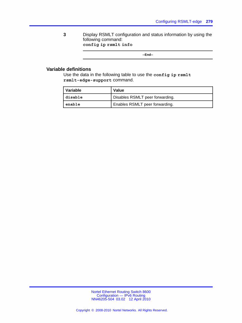
Configuring RSMLT-edge 279
3 Display RSMLT configuration and status information by using thefollowing command:config ip rsmlt info
--End--
Variable definitionsUse the data in the following table to use the config ip rsmltrsmlt-edge-support command.
Variable Value
disable Disables RSMLT peer forwarding.
enable Enables RSMLT peer forwarding.
Nortel Ethernet Routing Switch 8600Configuration — IPv6 Routing
NN46205-504 03.02 12 April 2010
Copyright © 2008-2010 Nortel Networks. All Rights Reserved.
.

280 IPv6 RSMLT configuration using the CLI
Nortel Ethernet Routing Switch 8600Configuration — IPv6 Routing
NN46205-504 03.02 12 April 2010
Copyright © 2008-2010 Nortel Networks. All Rights Reserved.
.

281.
IPv6 RSMLT configuration using theNNCLI
Routed Split MultiLink Trunking (RSMLT) forwards packets in the event ofcore router failures, thus minimizing dropped packets during the routingprotocol convergence.
To configure IPv6 RSMLT functionality, use the same set of commandsas required for IPv4 RSMLT. RSMLT configuration on a given VLANsimultaneously affects both IPv4 and IPv6. For example, the followingcommand is used for configuring IPv6 RSMLT on a VLAN:
(config-if)# ip rsmlt
All options apply equally to IPv6 and IPv4 RSMLT.
Note that the preceding command enables IPv6 RSMLT on a VLAN evenin the absence of IPv4 configuration on the VLAN.
RSMLT configuration proceduresRefer to the following procedures to configure RSMLT.
RSMLT navigation
• “Job aid: Roadmap of IPv6 RSMLT NNCLI commands” (page 281)
• “Configuring RSMLT on a VLAN” (page 282)
• “Showing IP RSMLT information” (page 283)
• “Configuring RSMLT-edge” (page 284)
Job aid: Roadmap of IPv6 RSMLT NNCLI commandsThe following table lists the commands and their parameters that you useto complete the procedures in this section.
Nortel Ethernet Routing Switch 8600Configuration — IPv6 Routing
NN46205-504 03.02 12 April 2010
Copyright © 2008-2010 Nortel Networks. All Rights Reserved.
.

282 IPv6 RSMLT configuration using the NNCLI
Table 22Roadmap of RSMLT commands
Command Parameter
PrivExec Mode
show ip rsmlt edge-support
<local|peer>
Interface Configuration Mode
ip rsmlt holddown-timer <0-3600>
holdup-timer <seconds>
Global Configuration Mode
ip rsmlt edge-support
no ip rsmlt peer-address
Configuring RSMLT on a VLANYou can configure RSMLT on each IP VLAN interface.
Prerequisites
• Access VLAN Interface Configuration Mode.
• The IPv6 routing protocol must be enabled on the VLAN interfaces.
• VLANs with Layer 3 interfaces must also participate in Split MultiLinkTrunking (SMLT).
Procedure steps
Step Action
1 Enable RSMLT on a VLAN by using the following command:ip rsmlt
Use the no operator to disable RSMLT:no ip rsmlt
To set this value to the default value, use the default operatorwith this command.
--End--
Variable definitionsUse the data in the following table to use the ip rsmlt command.
Nortel Ethernet Routing Switch 8600Configuration — IPv6 Routing
NN46205-504 03.02 12 April 2010
Copyright © 2008-2010 Nortel Networks. All Rights Reserved.
.

Showing IP RSMLT information 283
Variable Value
holddown-timer <0-3600> Defines how long the RSMLT switch does notparticipate in Layer 3 forwarding.
• 0-3600 is the timer value in seconds.
To set this value to the default value, use thedefault operator with this command.
Nortel recommends that you configure thisvalue to be longer than the anticipated routingprotocol convergence.
holdup-timer <seconds> Defines how long the RSMLT switch maintainsforwarding for its peer.
• seconds is the timer value in seconds.The value is a range from 0 to 3600seconds or 9999. 9999 means infinity.
To set this value to the default value, use thedefault operator with this command.
Showing IP RSMLT informationShow IP RSMLT information to view data about all RSMLT interfaces. Theoutput of the command includes the IPv6 formation for the local and peernodes.
Prerequisites
• Access privExec Configuration Mode or Global Configuration Mode.
Procedure steps
Step Action
1 Display RSMLT information about the interface by using thefollowing command:show ip rsmlt [<local|peer>]
--End--
Variable definitionsUse the information in the following command to complete the show iprsmlt command.
Nortel Ethernet Routing Switch 8600Configuration — IPv6 Routing
NN46205-504 03.02 12 April 2010
Copyright © 2008-2010 Nortel Networks. All Rights Reserved.
.

284 IPv6 RSMLT configuration using the NNCLI
Table 23show ip rsmlt info command
Variable Value
[<local|peer>]
Specifies values for the local or peer switch.
Job aidThe following table shows the field descriptions for theshow ip rsmlt[<local|peer>]command.
Table 24show ip rsmlt info command
Parameter Description
VID Indicates the VLAN ID.
IP Indicates the IP address of the router.
MAC Indicates the MAC address assigned.
ADMIN Indicates the administrative status of RSMLT on the router.
OPER Indicates the operational status of RSMLT on the router.
HDTMR Indicates the hold-down timer value in the range of 0 to 3600seconds.
HUTMR Indicates the hold-up timer value in the range of 0 to 3600seconds or 9999. 9999 means infinity.
HDT REMAIN Indicates the time remaining of the hold-down timer.
HUT REMAIN Indicates the time remaining of the hold-up timer.
SMLT ID Indicates the Split MultiLink Trunk ID.
SLT ID Indicates the SLT ID.
Configuring RSMLT-edgeConfigure RSMLT-edge to store the RSMLT peer MAC/IP address-pair inits local config file and restore the configuration if the peer does not restoreafter a simultaneous reboot of both RSMLT-peer switches. If enabled, allpeer MAC/IP information for all RSMLT-enabled VLANs are saved duringnext the save config command.
Prerequisites
• Access Global configuration mode.
Nortel Ethernet Routing Switch 8600Configuration — IPv6 Routing
NN46205-504 03.02 12 April 2010
Copyright © 2008-2010 Nortel Networks. All Rights Reserved.
.

Configuring RSMLT-edge 285
Procedure steps
Step Action
1 Enable RSMLT-edge by using the following command:ip rsmlt edge-support
Use the no operator to disable RSMLT-edge:no ip rsmlt edge-support
2 Clear RSMLT peer information and delete the RSMLT peeraddress by using the following command:no ip rsmlt peer-address <vlan ID>
3 Display RSMLT-edge status information by using the followingcommand:show ip rsmlt edge-support
--End--
Variable definitionsUse the data in the following table to use the no ip rsmltpeer-address command.
Variable Value
vlan ID The ID of the VLAN in the range of 0 to 4094.
Nortel Ethernet Routing Switch 8600Configuration — IPv6 Routing
NN46205-504 03.02 12 April 2010
Copyright © 2008-2010 Nortel Networks. All Rights Reserved.
.

286 IPv6 RSMLT configuration using the NNCLI
Nortel Ethernet Routing Switch 8600Configuration — IPv6 Routing
NN46205-504 03.02 12 April 2010
Copyright © 2008-2010 Nortel Networks. All Rights Reserved.
.

287.
IPv4-to-IPv6 transition mechanismconfiguration using Enterprise DeviceManager
This section describes how to use Enterprise Device Manager to configuretransition mechanisms, or tunnels, for IPv6 traffic through IPv4 networks.For conceptual information about tunnels, see “IPv6 routing fundamentals”(page 25).
Prerequisites to IPv4-to-IPv6 transition mechanism configuration• Both the source and destination devices must use IPv6 and IPv4
addresses.
IPv4-to-IPv6 transition mechanism configuration navigation• “Configuring the local VLAN or brouter port” (page 287)
• “Configuring the destination VLAN or brouter port” (page 289)
• “Configuring OSPF on a tunnel” (page 290)
• “Deleting a tunnel” (page 291)
• “Modifying tunnel hop limits” (page 291)
Configuring the local VLAN or brouter portConfigure a tunnel for IPv6 VLANs or brouter ports to communicatethrough an IPv4 network. Manual tunnels are point-to-point, so youconfigure both source and destination addresses. You must configure bothIPv6 and IPv4 addresses for both source and destination devices. TheIPv6 addresses must represent the same network, for example 6666::1/96and 6666::2/96.
Nortel Ethernet Routing Switch 8600Configuration — IPv6 Routing
NN46205-504 03.02 12 April 2010
Copyright © 2008-2010 Nortel Networks. All Rights Reserved.
.

288 IPv4-to-IPv6 transition mechanism configuration using Enterprise Device Manager
Procedure steps
Step Action
1 In the navigation tree, open the following folders:Configuration,IPv6.
2 Double-click Tunnel.
3 Click Insert.
4 In the LocalAddress box, click the button and select the IPv4address for the local VLAN or brouter port.
5 In the RemoteAddress box, type the IPv4 address for thedestination VLAN or brouter port.
6 In the EncapsMethod area, select manual.
7 In the ID box, type a number to represent the tunnel.
8 In the IPv6AddressAddr box, type the IPv6 address assigned tothe tunnel VLAN or brouter port.
9 In the IPv6AddressPrefixLength box, type the number of bits toadvertise in the IPv6 address.
10 Click Insert.
After you create the tunnel, the Local Address tab displays theIPv4 addresses associated with the tunnel.
--End--
Variable definitionsUse the data in the following table to use the Tunnel tab.
Variable Value
Address Type Displays the address type for the tunnel: IPv4 forIPv6 packets encapsulated in IPv4.
LocalAddress Identifies the local endpoint address of the tunnel.
RemoteAddress Identifies the remote endpoint of the tunnel.
EncapsMethod Displays the tunnel mode: IPv6 for manuallyconfigured tunnels and sixtoFour for automaticallyconfigured tunnels.The default value is manual.
ID Identifies the tunnel number.
IfIndex Displays a unique value that identifies the tunnelinterface internally. The value is derived from thetunnel ID.
Nortel Ethernet Routing Switch 8600Configuration — IPv6 Routing
NN46205-504 03.02 12 April 2010
Copyright © 2008-2010 Nortel Networks. All Rights Reserved.
.

Configuring the destination VLAN or brouter port 289
Configuring the destination VLAN or brouter portUse the following procedure to configure a tunnel for IPv6 VLANs orbrouter ports to communicate through an IPv4 network. Manual tunnelsare point-to-point, so you configure both source and destination addresses.You must configure both IPv6 and IPv4 addresses for both source anddestination devices. The IPv6 addresses must represent the samenetwork, for example 6666::1/96 and 6666::2/96.
Procedure steps
Step Action
1 In the navigation tree, open the following folders:Configuration,IPv6.
2 Double-click Tunnel.
3 Click Insert.
4 In the LocalAddress box, click the button and select the IPv4address for the destination VLAN or brouter port.
5 In the RemoteAddress box, type the IPv4 address for the localVLAN or brouter port.
6 In the EncapsMethod area, select manual.
7 In the ID box, type a number to represent the tunnel.
8 In the IPv6AddressAddr box, type the IPv6 address that youconfigured for the tunnel VLAN or brouter port for the destinationVLAN or brouter port.
9 In the IPv6AddressPrefixLength box, type the number of bits toadvertise in the IPv6 address.
10 Click Insert.
After you create the tunnel, the Local Address tab displays theIPv4 addresses associated with the tunnel.
--End--
Variable definitionsUse the data in the following table to use the Tunnel tab.
Variable Value
Address Type Displays the address type for the tunnel: IPv4 forIPv6 packets encapsulated in IPv4.
LocalAddress Identifies the local endpoint address of the tunnel.
RemoteAddress Identifies the remote endpoint of the tunnel.
Nortel Ethernet Routing Switch 8600Configuration — IPv6 Routing
NN46205-504 03.02 12 April 2010
Copyright © 2008-2010 Nortel Networks. All Rights Reserved.
.

290 IPv4-to-IPv6 transition mechanism configuration using Enterprise Device Manager
Variable Value
EncapsMethod Displays the tunnel mode: IPv6 for manuallyconfigured tunnels and sixtoFour for automaticallyconfigured tunnels.
ID Identifies the tunnel number.
IfIndex Displays a unique value that identifies the tunnelinterface internally. The value is derived from thetunnel ID.
Configuring OSPF on a tunnelConfigure the Open Shortest Path First (OSPF) protocol on IPv6 tunnels tosupport dynamic routing on the tunnel.
Procedure steps
Step Action
1 In the navigation tree, open the following folders:Configuration,IPv6.
2 Double-click Tunnel.
3 Select the tunnel on which to configure OSPF.
4 Click IPv6 OSPF.
The OSPF Interface tab appears.
5 Click Insert.
6 In the AreaId box, click the button and select the required areaID.
7 In the AdminStat area, select enabled.
8 In the RtrPriority box, modify the priority value if required.
9 Modify values in the TransitDelay, RetransitInterval,HelloInterval, RtrDeadInterval, or PollInterval boxes, ifrequired.
10 In the MulticastForwarding area, select the required option:blocked, multicast, or unicast.
11 Select the Demand check box to enable demand for aninstance.
12 In the Metric box, type the metric value for a demand for aninstance.
13 In the InstId box, type the instance ID.
14 Click Insert.
Nortel Ethernet Routing Switch 8600Configuration — IPv6 Routing
NN46205-504 03.02 12 April 2010
Copyright © 2008-2010 Nortel Networks. All Rights Reserved.
.

Modifying tunnel hop limits 291
15 On the OSPF Interface tab, click Apply.
--End--
Deleting a tunnelDelete a tunnel to remove it from the configuration.
Procedure steps
Step Action
1 In the navigation tree, open the following folders:Configuration,IPv6.
2 Double-click Tunnel.
3 Select the tunnel to delete.
4 Click Delete.
--End--
Modifying tunnel hop limitsModify tunnel hop limits to update hop limit values on previously configuredtunnels.
Procedure steps
Step Action
1 In the navigation tree, open the following folders:Configuration,IPv6.
2 Double-click Tunnel.
3 Click the Tunnel Interface tab.
4 In the row for the tunnel to configure, double-click the HopLimitcolumn to modify the displayed information as required.
5 Click Apply.
--End--
Variable definitionsUse the data in the following table to use the Tunnel Interface tab.
Nortel Ethernet Routing Switch 8600Configuration — IPv6 Routing
NN46205-504 03.02 12 April 2010
Copyright © 2008-2010 Nortel Networks. All Rights Reserved.
.

292 IPv4-to-IPv6 transition mechanism configuration using Enterprise Device Manager
Variable Value
Index Identifies the tunnel interface internally. The value isderived from the tunnel ID.
EncapsMethod Displays the tunnel mode: IPv6 for manually configuredtunnels and 6to4 for automatically configured tunnels.
HopLimit Configures the maximum number of hops in the tunnel.The default value is 255.
Security Indicates the type of security on the tunnel interface.
TOS Displays the method used to configure the high 6 bits(the differentiated services codepoint) of the IPv4 typeof service (TOS) or IPv6 traffic class in the outer IPheader. A value of -1 indicates that the bits are copiedfrom the payload header. A value of -2 indicates thata traffic conditioner is invoked and more informationcan be available in a traffic conditioner MIB module.A value from 0 to 63 indicates that the bit field isconfigured to the indicated value.
FlowLabel Displays the method used to set the IPv6 Flow Labelvalue. This object need not be present in rows wheretunnelIfAddressType indicates the tunnel is not overIPv6. A value of -1 indicates that a traffic conditioneris invoked and more information can be available ina traffic conditioner MIB. Any other value indicatesthat the Flow Label field is configured to the indicatedvalue.
AddressType Displays Manual for a manually configured tunnel, orsixToFour for autoconfigured tunnels.
LocalInetAddress Identifies the local endpoint address of the tunnel.
RemoteInetAddress Identifies the remote endpoint of the tunnel.
EncapsLimit Displays the address of the local endpoint of thetunnel (that is, the source address used in the outerIP header). If the address is unknown, the value is0.0.0.0 for IPv4 or :: for IPv6. The tunnelIfAddressTypedisplays the object type.
Nortel Ethernet Routing Switch 8600Configuration — IPv6 Routing
NN46205-504 03.02 12 April 2010
Copyright © 2008-2010 Nortel Networks. All Rights Reserved.
.

293.
IPv4-to-IPv6 transition mechanismconfiguration using the CLI
This chapter describes how to use the CLI to configure IPv6 transitionmechanisms, or tunnels. For conceptual information about tunnels, see“IPv6 routing fundamentals” (page 25).
Prerequisites to IPv4-to-IPv6 transition mechanism configuration• You must configure the local and remote switches with IPv4 addresses
that you can ping.
• You must configure the local and remote switches with one or more ofthe following protocols to route IPv4 traffic: Static, RIP, or OSPF.
IPv4-to-IPv6 transition mechanism configuration navigation• “Job aid: Roadmap of tunnel configuration CLI commands” (page 293)
• “Configuring manual tunnels” (page 294)
• “Configuring OSPF on a tunnel” (page 296)
• “Deleting a tunnel” (page 298)
Job aid: Roadmap of tunnel configuration CLI commandsThe following table lists the commands and parameters that you use toperform the procedures in this chapter.
Table 25Job aid: Roadmap of tunnel configuration CLI commands
Command Parameter
info
delete
config ipv6 tunnel <tunnel id> createlocal-addr <source ipv4 address>ipv6addr <source ipv6address/prefix-lenth> remot-address <dstipv4address>
hop-limit <value>
Nortel Ethernet Routing Switch 8600Configuration — IPv6 Routing
NN46205-504 03.02 12 April 2010
Copyright © 2008-2010 Nortel Networks. All Rights Reserved.
.

294 IPv4-to-IPv6 transition mechanism configuration using the CLI
Table 25Job aid: Roadmap of tunnel configuration CLI commands (cont’d.)
Command Parameter
info
admin-status <enable|disable>
create <area> [priority <value>][metric <value>] [retransmit-interval <value>] [transit-delay<value>] [hello-interval <value>][dead-interval <value>]
delete
hello-interval <seconds>
dead-interval <seconds>
poll-interval <seconds>
metric <metric>
priority <priority>
retransmit-interval <seconds>
config ipv6 tunnel <tunnel-id> ospf
transit-delay <seconds>
Configuring manual tunnelsCreate a tunnel to transfer traffic between IPv6 devices in an IPv4 network.Configure manual tunnels when you want to define both the local anddestination addresses.
Use this procedure to configure the tunnel at both the source anddestination addresses.
Procedure steps
Step Action
1 Configure the tunnel at the source by using the followingcommand:
config ipv6 tunnel <tunnel id> create local-addr<source ipv4 address> ipv6addr <source ipv6address/prefix length> remote-address <remote ipv4address>
2 Configure the tunnel at the destination by using the followingcommand:
config ipv6 tunnel <tunnel id> create local-addr<remote ipv4 address> ipv6 addr <remote ipv6
Nortel Ethernet Routing Switch 8600Configuration — IPv6 Routing
NN46205-504 03.02 12 April 2010
Copyright © 2008-2010 Nortel Networks. All Rights Reserved.
.

Configuring manual tunnels 295
address/prefix length> remote-address <source ipv4address>
--End--
Variable definitionsUse the data in the following table to use the config ipv6 tunnelcommand.
Variable Value
create [localaddr <value> ][ipv6addr <value>] [remote-address<value>]
Creates the tunnel for a VLAN or brouter port.
• local addr <value> configures theaddress for the local device.
• ipv6addr <value> configures thelocal address for the tunneled device inIPv6/prefix-length format.
• remote-address <value> configures theaddress for the device that is tunneled to inIPv4 or IPv6/prefix-length format.
delete Deletes the tunnel.
hop-limit <value> Configures the maximum number of hops thata packet can make before it is dropped.
• value is in the range 0–255.
info Displays the current settings for the command.
tunnel id Specifies the ID number of the tunnel in therange of 1-5000.
Example of configuring manual tunnelsProcedure steps
Step Action
1 Configure the tunnel at the source.
ERS-8610:5#config ipv6 tunnel 1044 create localaddr 20.10.10.107 ipv6addr 0100:0200:0300:0004:0005:0006:0000:aa01/80 remote-address 10.20.20.105
2 Configure the tunnel at the destination.
Nortel Ethernet Routing Switch 8600Configuration — IPv6 Routing
NN46205-504 03.02 12 April 2010
Copyright © 2008-2010 Nortel Networks. All Rights Reserved.
.

296 IPv4-to-IPv6 transition mechanism configuration using the CLI
ERS-8610:5#config ipv6 tunnel 1045 create localaddr 10.20.20.105 ipv6addr 0100:0200:0300:0004:0005:0006:0000:aa02/80 remote-address 20.10.10.107
--End--
Configuring OSPF on a tunnelConfigure OSPF on a VLAN or brouter tunnel to create a dynamic IPv6tunnel on the OSPF interface.
Procedure steps
Step Action
1 Configure OSPF on a tunnel by using the following command:
config ipv6 tunnel <tunnel-id> ospf
--End--
Variable definitionsUse the data in the following table to use the config ipv6 tunnel ospfcommand.
Variable Value
admin-status<enable|disable>
Configures the state (enabled or disabled) ofthe OSPF interface.
create <area>[priority <value>] [metric <value> ][retransmit-interval<value> ] [transit-delay <value> ][hello-interval <value>] [dead-interval<value> ] [type <value>]
Creates an OSPF interface.
• <area> is the area IP address (0.0.0.0 to255.255.255.255) {a.b.c.d}.
• priority <value> is the priority in therange 0–255.
• metric <value> is the metric in the range0–65535.
• retransmit-interval <value> is theretransmit interval in the range 1–1800seconds.
• transit-delay <value> is the transitdelay in the range 1–1800 seconds.
Nortel Ethernet Routing Switch 8600Configuration — IPv6 Routing
NN46205-504 03.02 12 April 2010
Copyright © 2008-2010 Nortel Networks. All Rights Reserved.
.

Configuring OSPF on a tunnel 297
Variable Value
• hello-interval <value> is the hellointerval in the range 1–65535 seconds.
• dead-interval <value> is the deadinterval in the range 1–4095 seconds.
dead-interval <seconds> Configures the OSPF dead interval for theinterface.
seconds is the number of seconds the switchOSPF neighbors wait before determining thatthis OSPF router is down. The range is from1–4095. This value must be at least four timesthe Hello interval value. The default is 40.
delete Deletes an OSPF interface.
hello-interval<seconds>
Configures the OSPF hello interval for theinterface.
seconds is the number of seconds betweenhello packets sent on this interface. The rangeis 1–65535. The default is 10.
ATTENTIONWhen you change the hello interval values,you must save the configuration file andreboot the switch for the values to berestored and checked for consistency.
info Displays OSPF characteristics for theinterface.
metric <metric> Configures the OSPF metric for the interface.The switch advertises the metric in router linkadvertisements.
• metric is the range 0–65535.
poll-interval <seconds> Configures the polling interval for the OSPFinterface in seconds.
• seconds is 0–2147483647.
Nortel Ethernet Routing Switch 8600Configuration — IPv6 Routing
NN46205-504 03.02 12 April 2010
Copyright © 2008-2010 Nortel Networks. All Rights Reserved.
.

298 IPv4-to-IPv6 transition mechanism configuration using the CLI
Variable Value
priority <priority> Configures the OSPF priority for the interfaceduring the election process for the designatedrouter. The interface with the highest prioritynumber is the designated router. The interfacewith the second-highest priority becomesthe backup designated router. If the priorityis 0, the interface cannot become either thedesignated router or a backup. The priorityis used only during election of the designatedrouter and backup designated router.
priority is in the range 0–255. The defaultis 1.
retransmit-interval<seconds>
Configures the retransmit interval for the OSPFinterface; the number of seconds betweenlink-state advertisement retransmissions.
seconds is an integer 1–1800.
transit-delay <seconds> Configures the transit delay time for the OSPFinterface, the estimated time in secondsrequired to transmit a link-state update packetover the interface.
seconds is an integer 1–1,800.
tunnel-id Specifies the ID number of the tunnel in therange of 1–2147477248.
Deleting a tunnelDelete a configured tunnel to remove it from the configuration.
Procedure steps
Step Action
1 Delete a tunnel by using the following command:
config ipv6 tunnel <tunnel ID> delete
--End--
Variable definitionsUse the data in the following table to use the config ipv6 tunneldelete command.
Nortel Ethernet Routing Switch 8600Configuration — IPv6 Routing
NN46205-504 03.02 12 April 2010
Copyright © 2008-2010 Nortel Networks. All Rights Reserved.
.

Deleting a tunnel 299
Variable Value
tunnel-id Specifies the ID number of the tunnelin the range of 1–2147477248.
Nortel Ethernet Routing Switch 8600Configuration — IPv6 Routing
NN46205-504 03.02 12 April 2010
Copyright © 2008-2010 Nortel Networks. All Rights Reserved.
.

300 IPv4-to-IPv6 transition mechanism configuration using the CLI
Nortel Ethernet Routing Switch 8600Configuration — IPv6 Routing
NN46205-504 03.02 12 April 2010
Copyright © 2008-2010 Nortel Networks. All Rights Reserved.
.

301.
IPv4-to-IPv6 transition mechanismconfiguration using the NNCLI
This section describes how to use the NNCLI to configure IPv6 transitionmechanisms, or tunnels. For conceptual information about tunnels, see“IPv6 routing fundamentals” (page 25).
Prerequisites to IPv4-to-IPv6 transition mechanism configuration• You must configure the local and remote switches with IPv4 addresses
that you can ping.
• You must configure the local and remote switches with one or more ofthe following protocols to route IPv4 traffic: Static, RIP, or OSPF.
IPv4-to-IPv6 transition mechanism configuration navigation• “Job aid: Roadmap of tunnel configuration NNCLI commands” (page
301)
• “Configuring manual tunnels” (page 302)
• “Configuring OSPF on a tunnel” (page 304)
Job aid: Roadmap of tunnel configuration NNCLI commandsThe following table lists the commands and their parameters that you useto complete the procedures in this section.
Table 26Job aid: Roadmap of tunnel configuration NNCLI commands
Command Parameter
Global Configuration mode
Nortel Ethernet Routing Switch 8600Configuration — IPv6 Routing
NN46205-504 03.02 12 April 2010
Copyright © 2008-2010 Nortel Networks. All Rights Reserved.
.

302 IPv4-to-IPv6 transition mechanism configuration using the NNCLI
Table 26Job aid: Roadmap of tunnel configuration NNCLI commands (cont’d.)
Command Parameter
source <A.B.C.D> address <ipv6address/prefix-len> destination<A.B.C.D>
ipv6 tunnel <tunnel id>
hop-limit <value>
OSPF Router Configuration mode
dead-interval <seconds>
enable
hello-interval <seconds>
metric <value>
poll-interval <seconds>
priority <value>
retransmit-interval <seconds>
transmit-delay <seconds>
ipv6 tunnel <tunnel id>
area <A.B.C.D> [dead-interval<seconds>] [hello-interval <seconds>][metric <value>] [priority <value>][retransmit-interval <seconds>][transmit-delay <seconds>]
Configuring manual tunnelsCreate a tunnel to transfer traffic between IPv6 devices in an IPv4 network.Configure manual tunnels when you want to define both the local anddestination addresses.
Use this procedure to configure the tunnel at both the source anddestination addresses.
Prerequisites
• You must log on to the Global Configuration mode in the NNCLI.
Procedure steps
Step Action
1 Configure the tunnel at the source and destination by using thefollowing command:
Nortel Ethernet Routing Switch 8600Configuration — IPv6 Routing
NN46205-504 03.02 12 April 2010
Copyright © 2008-2010 Nortel Networks. All Rights Reserved.
.

Configuring manual tunnels 303
ipv6 tunnel <tunnel id> source <A.B.C.D> address <ipv6address/prefix-len> destination <A.B.C.D>
2 Configure the hop limit by using the following command:
ipv6 tunnel <tunnel id> hop-limit <value>
--End--
Variable definitionsUse the data in the following table to use the ipv6 tunnel command.
Variable Value
address <ipv6address/prefix-len>
Configures the local address for the tunneleddevice in IPv6/prefix-length format.
destination <A.B.C.D> Configures the address for the device that istunneled to in IPv4 or IPv6/prefix-length format.
hop-limit <value> Configures the maximum number of hops thata packet can make before it is dropped.
• value is in the range 0–255.
To set this option to the default value, use thedefault operator with the command.The default value is 255.
source <A.B.C.D> Configures the address for the local device.
tunnel id Specifies the ID number of the tunnel in therange of 1-5000.
Example of configuring manual tunnelsProcedure steps
Step Action
1 Configure the tunnel at the source.
ERS-8606:5(config)#ipv6 tunnel 1044 source20.10.10.107 address 0100:0200:0300:0004:0005:0006:0000:aa01/80 destination 10.20.20.105
2 Configure the tunnel at the destination.
ERS-8606:5(config)#ipv6 tunnel 1045 source10.20.20.105 address 0100:0200:0300:0004:0005:0006:0000:aa02/80 destination 20.10.10.107
--End--
Nortel Ethernet Routing Switch 8600Configuration — IPv6 Routing
NN46205-504 03.02 12 April 2010
Copyright © 2008-2010 Nortel Networks. All Rights Reserved.
.

304 IPv4-to-IPv6 transition mechanism configuration using the NNCLI
Configuring OSPF on a tunnelConfigure OSPF on a VLAN or brouter tunnel to create a dynamic IPv6tunnel on the OSPF interface.
Prerequisites
• You must log on to the Global Configuration mode in the NNCLI.
Procedure steps
Step Action
1 Configure OSPF on a tunnel by using the following command:
ipv6 tunnel <tunnel id> [dead-interval <seconds>]enable [hello-interval <seconds>] [metric <value>][poll-interval <seconds>] [priority <value>][retransmit-interval <seconds>] [transmit-delay<seconds>]
2 Configure the OSPF area for the tunnel by using the followingcommand:
ipv6 tunnel <tunnel id> area <A.B.C.D> [dead-interval<seconds>] [hello-interval <seconds>] [metric <value>][priority <value>] [retransmit-interval <seconds>][transmit-delay <seconds>]
--End--
Variable definitionsUse the data in the following table to use the ipv6 tunnel command.
Variable Value
area <A.B.C.D> Configures the area IP address (0.0.0.0 to255.255.255.255) {a.b.c.d}.
Nortel Ethernet Routing Switch 8600Configuration — IPv6 Routing
NN46205-504 03.02 12 April 2010
Copyright © 2008-2010 Nortel Networks. All Rights Reserved.
.

Configuring OSPF on a tunnel 305
Variable Value
dead-interval <seconds> Configures the OSPF dead interval for theinterface.
• seconds is the number of secondsthe switch OSPF neighbors wait beforedetermining that this OSPF router is down.The range is from 1-4095. This value mustbe at least four times the hello intervalvalue. The default is 40.
To set this option to the default value, use thedefault operator with the command.
enable Configures the state (enabled or disabled) ofthe OSPF interface. To set this option to thedefault value, use the default operator withthe command.
hello-interval<seconds>
Configures the OSPF Hello interval for theinterface.
• seconds is the number of secondsbetween hello packets sent on thisinterface. The range is 1–65535. Thedefault is 10.
ATTENTIONWhen you change the hello interval values,you must save the configuration file andreboot the switch for the values to berestored and checked for consistency.
To set this option to the default value, use thedefault operator with the command.
metric <value> Configures the OSPF metric for the interface.The switch advertises the metric in router linkadvertisements.
• value is the range 0–65535.
To set this option to the default value, use thedefault operator with the command.The default value is 1.
Nortel Ethernet Routing Switch 8600Configuration — IPv6 Routing
NN46205-504 03.02 12 April 2010
Copyright © 2008-2010 Nortel Networks. All Rights Reserved.
.

306 IPv4-to-IPv6 transition mechanism configuration using the NNCLI
Variable Value
poll-interval <seconds> Configures the polling interval for the OSPFinterface in seconds.
• seconds is between 1–2 147 483 647.
To set this option to the default value, use thedefault operator with the command.The default value is 120.
priority <value> Configures the OSPF priority for the interfaceduring the election process for the designatedrouter. The interface with the highest prioritynumber is the designated router. The interfacewith the second-highest priority becomesthe backup designated router. If the priorityis 0, the interface cannot become either thedesignated router or a backup. The priorityis used only during election of the designatedrouter and backup designated router.
• value is in the range 0–255. The defaultis 1.
To set this option to the default value, use thedefault operator with the command.
retransmit-interval<seconds>
Configures the retransmit interval for the OSPFinterface; the number of seconds betweenlink-state advertisement retransmissions.
• seconds is an integer between 1–1800.
To set this option to the default value, use thedefault operator with the command.The default value is 5.
transit-delay <seconds> Configures the transit delay time for the OSPFinterface, the estimated time in secondsrequired to transmit a link-state update packetover the interface.
• seconds is an integer between 1–1800.
To set this option to the default value, use thedefault operator with the command.The default value is 1.
tunnel-id Specifies the ID number of the tunnel in therange of 1-5000.
Nortel Ethernet Routing Switch 8600Configuration — IPv6 Routing
NN46205-504 03.02 12 April 2010
Copyright © 2008-2010 Nortel Networks. All Rights Reserved.
.

307.
Multicast protocol configuration usingEnterprise Device Manager
This chapter contains procedures to configure Multicast Listener Discovery(MLD).
MLD discovers devices soliciting multicast traffic to update multicasttables. This improves efficiency and saves bandwidth; only devices thatrequire multicast traffic receive it rather than every device on the network.
For more information about MLD concepts, see “IPv6 routingfundamentals” (page 25).
Multicast protocol configuration proceduresThis task flow shows you the sequence of procedures you perform toconfigure multicast routing protocols for IPv6. To link to any procedure,click the procedure in “Multicast protocol configuration navigation” (page308).
Nortel Ethernet Routing Switch 8600Configuration — IPv6 Routing
NN46205-504 03.02 12 April 2010
Copyright © 2008-2010 Nortel Networks. All Rights Reserved.
.

308 Multicast protocol configuration using Enterprise Device Manager
Figure 15Multicast protocol configurationprocedures
Multicast protocol configuration navigation
• “Configuring a multicast router” (page 308)
• “Configuring an MLD host” (page 309)
• “Configuring an MLD router interface” (page 310)
• “Viewing the MLD cache” (page 311)
Configuring a multicast routerConfigure a multicast router to enable Multicast Listening Discovery (MLD)on the router at a chassis level.
Procedure steps
Nortel Ethernet Routing Switch 8600Configuration — IPv6 Routing
NN46205-504 03.02 12 April 2010
Copyright © 2008-2010 Nortel Networks. All Rights Reserved.
.

Configuring an MLD host 309
Step Action
1 In the navigation tree, open the following folders:Configuration,Edit.
2 Double-click Chassis.
3 Click the Mcast Mlt Distribution tab.
4 Select the Enable check box to enable multicast multilink trunk(MLT) routing.
5 In the GrpMask box, type the group mask address in IPv4format. The default is 255.255.255.255.
6 In the SrcMask box, type the source mask address in IPv4format. The default is 255.255.255.255.
7 Select the RedistributeEnable check box to enableredistribution.
8 Click Apply.
--End--
Configuring an MLD hostConfigure the switch as an MLD host to listen to multicast packets.
Procedure steps
Step Action
1 In the navigation tree, open the following folders:Configuration,IPv6.
2 Double-click MLD.
3 Select the MulticastAdminStatus check box.
4 Click Apply.
--End--
Variable definitionsUse the data in the following table to configure the MLD Globals tab.
Variable Value
MulticastAdminStatus Select to configure the switch as anMLD host.
Nortel Ethernet Routing Switch 8600Configuration — IPv6 Routing
NN46205-504 03.02 12 April 2010
Copyright © 2008-2010 Nortel Networks. All Rights Reserved.
.
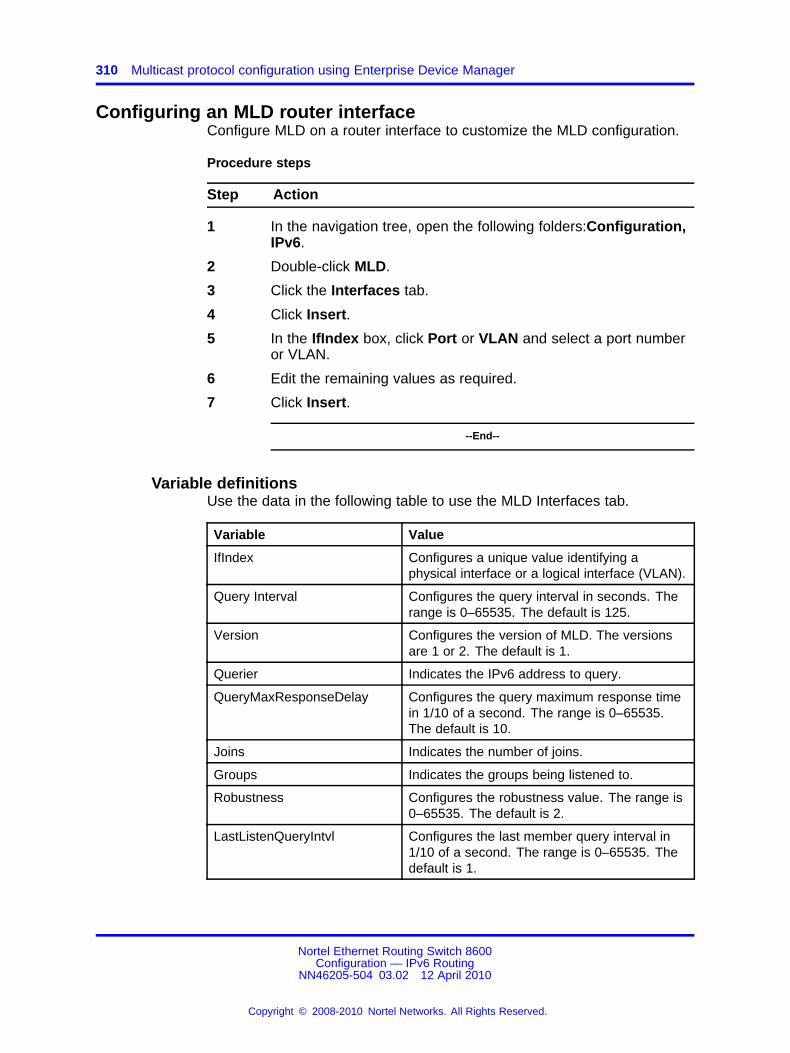
310 Multicast protocol configuration using Enterprise Device Manager
Configuring an MLD router interfaceConfigure MLD on a router interface to customize the MLD configuration.
Procedure steps
Step Action
1 In the navigation tree, open the following folders:Configuration,IPv6.
2 Double-click MLD.
3 Click the Interfaces tab.
4 Click Insert.
5 In the IfIndex box, click Port or VLAN and select a port numberor VLAN.
6 Edit the remaining values as required.
7 Click Insert.
--End--
Variable definitionsUse the data in the following table to use the MLD Interfaces tab.
Variable Value
IfIndex Configures a unique value identifying aphysical interface or a logical interface (VLAN).
Query Interval Configures the query interval in seconds. Therange is 0–65535. The default is 125.
Version Configures the version of MLD. The versionsare 1 or 2. The default is 1.
Querier Indicates the IPv6 address to query.
QueryMaxResponseDelay Configures the query maximum response timein 1/10 of a second. The range is 0–65535.The default is 10.
Joins Indicates the number of joins.
Groups Indicates the groups being listened to.
Robustness Configures the robustness value. The range is0–65535. The default is 2.
LastListenQueryIntvl Configures the last member query interval in1/10 of a second. The range is 0–65535. Thedefault is 1.
Nortel Ethernet Routing Switch 8600Configuration — IPv6 Routing
NN46205-504 03.02 12 April 2010
Copyright © 2008-2010 Nortel Networks. All Rights Reserved.
.

Viewing the MLD cache 311
Variable Value
QuerierUpTime Indicates the amount of time that the querier isenabled.
QuerierExpiryTime Inidcates the expiry time for the querier.
Viewing the MLD cacheView the MLD cache to see IPv6 multicast groups for which members existon an interface.
Procedure steps
Step Action
1 In the navigation tree, open the following folders:Configuration,IPv6.
2 Double-click MLD.
3 Click the Cached tab.
--End--
Variable definitionsUse the data in the following table to use the MLD Cached tab.
Variable Value
Address Displays the IPv6 address for the interface.
IfIndex Displays a unique value to identify a physical interfaceor a logical interface (VLAN).
Self Indicates if the local system is a member of the groupaddress on the current interface.
LastReporter Displays the source IPv6 address for the last receivedmembership report for the IPv6 multicast groupaddress on the current interface. If no membershipreport is received, the object value is 0::0.
UpTime Indicates the duration of time that MLD is enabled.
ExpiryTime Indicates the expiry time.
Nortel Ethernet Routing Switch 8600Configuration — IPv6 Routing
NN46205-504 03.02 12 April 2010
Copyright © 2008-2010 Nortel Networks. All Rights Reserved.
.

312 Multicast protocol configuration using Enterprise Device Manager
Nortel Ethernet Routing Switch 8600Configuration — IPv6 Routing
NN46205-504 03.02 12 April 2010
Copyright © 2008-2010 Nortel Networks. All Rights Reserved.
.
313.
Multicast protocol configuration usingthe CLI
This chapter describes the procedures to configure Multicast ListenerDiscovery (MLD) on your Nortel Ethernet Routing Switch 8600.
MLD provides group management capabilities by allowing hosts toinform routers of membership status within groups. MLD discovers thepresence of multicast listeners on directly attached links. MLD providesthe necessary information to route multicast packets to routers requiringmulticast traffic.
For more information about MLD concepts, see “IPv6 routingfundamentals” (page 25).
Multicast protocol configuration proceduresThis task flow shows you the sequence of procedures you perform toconfigure multicast routing protocols for IPv6. To link to any procedure,click the procedure in “Multicast protocol configuration navigation” (page314).
Nortel Ethernet Routing Switch 8600Configuration — IPv6 Routing
NN46205-504 03.02 12 April 2010
Copyright © 2008-2010 Nortel Networks. All Rights Reserved.
.

314 Multicast protocol configuration using the CLI
Figure 16Multicast protocol configuration procedures
Multicast protocol configuration navigation
• “Job aid: Roadmap of IPv6 multicast CLI commands” (page 314)
• “Enabling a multicast router” (page 315)
• “Enabling a VLAN for multicast routing” (page 315)
• “Configuring MLD on a VLAN” (page 316)
• “Enabling multicasting on a brouter port” (page 317)
• “Configuring MLD on a brouter port” (page 317)
Job aid: Roadmap of IPv6 multicast CLI commandsThe following table lists the commands and parameters that you use toperform the procedures in this chapter.
Nortel Ethernet Routing Switch 8600Configuration — IPv6 Routing
NN46205-504 03.02 12 April 2010
Copyright © 2008-2010 Nortel Networks. All Rights Reserved.
.

Enabling a VLAN for multicast routing 315
Table 27Job aid: Roadmap of IPv6 multicast CLI commands
Command Parameter
config ethernet <ports> ipv6 mcast<enable|disable>
info
last-memb-query-int <seconds>
query-interval <seconds>
query-maxresp <1seconds>
robustval <integer>
config ethernet <ports> ipv6 mld
version <1|2>
config ipv6 mcast <enable|disable> –
config vlan <vid> ipv6 mcast<enable|disable>
–
info
last-memb-query-int <seconds>
query-interval <seconds>
query-maxresp <1seconds>
robustval <integer>
config vlan <vid> ipv6 mld
version <1|2>
Enabling a multicast routerEnable the router for multicast traffic to globally enable the MLD protocol.
Procedure steps
Step Action
1 Enable the multicast router by using the following command:
config ipv6 mcast <enable|disable>
--End--
Enabling a VLAN for multicast routingConfigure a VLAN for multicast traffic to enable MLD on the VLAN.
Nortel Ethernet Routing Switch 8600Configuration — IPv6 Routing
NN46205-504 03.02 12 April 2010
Copyright © 2008-2010 Nortel Networks. All Rights Reserved.
.

316 Multicast protocol configuration using the CLI
Procedure steps
Step Action
1 Enable a VLAN for multicast routing by using the followingcommand:
config vlan <vid> ipv6 mcast <enable|disable>
--End--
Variable definitionsUse the data in the following table to use the config vlan ipv6 mcast<enable|disable> command.
Variable Value
vid Specifies a VLAN ID in the range of1–4094.
Configuring MLD on a VLANConfigure MLD on a VLAN to customize the configuration.
Procedure steps
Step Action
1 Configure MLD by using the following command:
config vlan <vid> ipv6 mld
--End--
Variable definitionsUse the data in the following table to use the config vlan ipv6 mldcommand.
Variable Value
info Displays the current VLAN MLD configurationsetting.
last-memb-query-int<seconds>
Configures the query interval time in 1/10 of asecond for the last member.
seconds is in the range 0–65535.
Nortel Ethernet Routing Switch 8600Configuration — IPv6 Routing
NN46205-504 03.02 12 April 2010
Copyright © 2008-2010 Nortel Networks. All Rights Reserved.
.

Configuring MLD on a brouter port 317
Variable Value
query-interval<seconds>
Configures the query interval time in 1/10 of asecond.
seconds is in the range 0–65535.
query-maxresp<1seconds>
The maximum query response time advertisedin MLD queries on this interface.
seconds is in the range 0–65535.
robustval <integer> Configures the robustness value.
integer is in the range 0–65535.
version <1|2> Configures the version of MLD to version 1 orversion 2.
vid Specifies a VLAN ID in the range of 1–4094.
Enabling multicasting on a brouter portConfigure multicasting on a brouter port to enable MLD on the port.
Procedure steps
Step Action
1 Enable multicasting by using the following command:
config ethernet <ports> ipv6 mcast <enable|disable>
--End--
Variable definitionsUse the data in the following table to use the config ethernet ipv6mcast command.
Variable Value
ports Specifies a port/slot or a port list.
Configuring MLD on a brouter portConfigure MLD on a brouter port to customize the configuration.
Procedure steps
Step Action
1 Configure MLD by using the following command:
Nortel Ethernet Routing Switch 8600Configuration — IPv6 Routing
NN46205-504 03.02 12 April 2010
Copyright © 2008-2010 Nortel Networks. All Rights Reserved.
.

318 Multicast protocol configuration using the CLI
config ethernet <ports> ipv6 mld
--End--
Variable definitionsUse the data in the following table to use the config ethernet ipv6mld command.
Variable Value
info Displays the current brouter port MLDconfiguration setting.
last-memb-query-int<seconds>
Configures the query interval time in 1/10 of asecond for the last member.
seconds is in the range 0–65535.
ports Specifies a port/slot or a port list.
query-interval<seconds>
Configures the query interval time in 1/10 of asecond.
seconds is in the range 0–65535.
query-maxresp<1seconds>
The maximum query response time advertisedin MLD queries on this interface.
seconds is in the range 0–65535.
robustval <integer> Configures the robustness value.
integer is in the range 0–65535.
version <1|2> Configures the version of MLD to version 1 orversion 2.
Nortel Ethernet Routing Switch 8600Configuration — IPv6 Routing
NN46205-504 03.02 12 April 2010
Copyright © 2008-2010 Nortel Networks. All Rights Reserved.
.

319.
Multicast protocol configuration usingthe NNCLI
This chapter describes the procedures used to configure Multicast ListenerDiscovery (MLD) on your Nortel Ethernet Routing Switch 8600.
MLD provides group management capabilities by allowing hosts toinform routers of membership status within groups. MLD discovers thepresence of multicast listeners on directly attached links. MLD providesthe necessary information to route multicast packets to routers requiringmulticast traffic.
For more information about MLD concepts, see “IPv6 routingfundamentals” (page 25).
Multicast protocol configuration proceduresThis task flow shows you the sequence of procedures you perform toconfigure multicast routing protocols for IPv6. To link to any procedure,click the procedure in “Multicast protocol configuration navigation” (page320).
Nortel Ethernet Routing Switch 8600Configuration — IPv6 Routing
NN46205-504 03.02 12 April 2010
Copyright © 2008-2010 Nortel Networks. All Rights Reserved.
.

320 Multicast protocol configuration using the NNCLI
Figure 17Multicast protocol configuration procedures
Multicast protocol configuration navigation
• “Job aid: Roadmap of IPv6 multicast NNCLI commands” (page 320)
• “Enabling a multicast router” (page 321)
• “Enabling a VLAN for multicast routing” (page 321)
• “Configuring MLD on a VLAN” (page 322)
• “Enabling multicasting on a brouter port” (page 323)
• “Configuring MLD on a brouter port” (page 324)
Job aid: Roadmap of IPv6 multicast NNCLI commandsThe following table lists the commands and parameters that you use toperform the procedures in this chapter.
Nortel Ethernet Routing Switch 8600Configuration — IPv6 Routing
NN46205-504 03.02 12 April 2010
Copyright © 2008-2010 Nortel Networks. All Rights Reserved.
.

Enabling a VLAN for multicast routing 321
Table 28Job aid: Roadmap of IPv6 multicast NNCLI commands
Command Parameter
Global Configuration mode
ipv6 multicast-routing –
Interface Configuration mode
mtu <bytes>
reachable-time <value>
ipv6 interface multicast-routing
retransmit-timer <value>
last-memb-query-int <value>
query-interval <value>
query-max-response-time <value>
robustval <value>
ipv6 mld
version <1|2>
Enabling a multicast routerEnable the router for multicast traffic to globally enable MLD.
Prerequisites
• You must log on to the Global Configuration mode in the NNCLI.
Procedure steps
Step Action
1 Enable the multicast router by using the following command:
ipv6 multicast-routing
--End--
Enabling a VLAN for multicast routingConfigure a VLAN for multicast traffic to enable MLD on the VLAN.
Prerequisites
• You must log on to the VLAN Interface Configuration mode in theNNCLI.
Nortel Ethernet Routing Switch 8600Configuration — IPv6 Routing
NN46205-504 03.02 12 April 2010
Copyright © 2008-2010 Nortel Networks. All Rights Reserved.
.

322 Multicast protocol configuration using the NNCLI
Procedure steps
Step Action
1 Enable a VLAN for multicast routing by using the followingcommand:
ipv6 interface multicast-routing [reachable-time<value>] [retransmit-timer <value>]
--End--
Variable definitionsUse the data in the following table to use the ipv6 interfacemulticast-routing command.
Variable Value
reachable-time <value> Configures the reachable time, inmilliseconds, for the interface. Therange is 0–3600000.
retransmit-timer <value> Configures the time between attemptsto transmit multicast packets, inmilliseconds, for the interface. Therange is 0–3600000.
Configuring MLD on a VLANConfigure MLD on a VLAN to customize the configuration.
Prerequisites
• You must log on to the VLAN Interface Configuration mode in theNNCLI.
Procedure steps
Step Action
1 Configure MLD by using the following command:
ipv6 mld [last-memb-query-int <value>] [query-interval<value>] [query-max-response-time <value>] [robustval<value>] [version <1|2>]
--End--
Nortel Ethernet Routing Switch 8600Configuration — IPv6 Routing
NN46205-504 03.02 12 April 2010
Copyright © 2008-2010 Nortel Networks. All Rights Reserved.
.

Enabling multicasting on a brouter port 323
Variable definitionsUse the data in the following table to use the ipv6 mld command.
Variable Value
last-memb-query-int<value>
Configures the query interval time in 1/10 of asecond for the last member.
value is in the range 0–65535.
The default value is 1.
query-interval <value> Configures the maximum query response timeadvertised in MLD queries on this interface.
value is in the range 0–65535.
The default value is 125.
query-max-response-time <value>
Configures the query interval time in 1/10 of asecond for the last member.
value is in the range 0–65535.
The default value is 10.
robustval <value> Configures the robustness value.
value is in the range 0–65535.
The default value is 2.
version <1|2> Configures the version of MLD to version 1 orversion 2.The default value is 1.
Enabling multicasting on a brouter portConfigure multicasting on a brouter port to enable MLD on the port.
Prerequisites
• You must log on to the Interface Configuration mode in the NNCLI.
Procedure steps
Step Action
1 Enable multicasting by using the following command:
Nortel Ethernet Routing Switch 8600Configuration — IPv6 Routing
NN46205-504 03.02 12 April 2010
Copyright © 2008-2010 Nortel Networks. All Rights Reserved.
.

324 Multicast protocol configuration using the NNCLI
ipv6 interface multicast-routing [reachable-time<value>] [retransmit-timer <value>]
--End--
Variable definitionsUse the data in the following table to use the ipv6 interfacemulticast-routing command.
Variable Value
reachable-time <value> Configures the reachable time, inmilliseconds, for the interface. Therange is –03600000.
retransmit-timer <value> Configures the time between attemptsto transmit multicast packets, inmilliseconds, for the interface. Therange is 0–3600000.
Configuring MLD on a brouter portConfigure MLD on a brouter port to customize the configuration.
Prerequisites
• You must log on to the Interface Configuration mode in the NNCLI.
Procedure steps
Step Action
1 Configure MLD by using the following command:
ipv6 mld [last-memb-query-int <value>] [query-interval<value>] [query-max-response-time <value>] [robustval<value>] [version <1|2>]
--End--
Variable definitionsUse the data in the following table to use the ipv6 mld command.
Nortel Ethernet Routing Switch 8600Configuration — IPv6 Routing
NN46205-504 03.02 12 April 2010
Copyright © 2008-2010 Nortel Networks. All Rights Reserved.
.
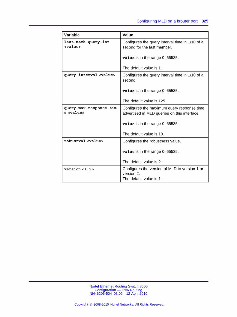
Configuring MLD on a brouter port 325
Variable Value
last-memb-query-int<value>
Configures the query interval time in 1/10 of asecond for the last member.
value is in the range 0–65535.
The default value is 1.
query-interval <value> Configures the query interval time in 1/10 of asecond.
value is in the range 0–65535.
The default value is 125.
query-max-response-time <value>
Configures the maximum query response timeadvertised in MLD queries on this interface.
value is in the range 0–65535.
The default value is 10.
robustval <value> Configures the robustness value.
value is in the range 0–65535.
The default value is 2.
version <1|2> Configures the version of MLD to version 1 orversion 2.The default value is 1.
Nortel Ethernet Routing Switch 8600Configuration — IPv6 Routing
NN46205-504 03.02 12 April 2010
Copyright © 2008-2010 Nortel Networks. All Rights Reserved.
.

326 Multicast protocol configuration using the NNCLI
Nortel Ethernet Routing Switch 8600Configuration — IPv6 Routing
NN46205-504 03.02 12 April 2010
Copyright © 2008-2010 Nortel Networks. All Rights Reserved.
.
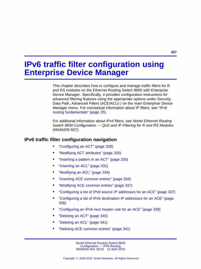
327.
IPv6 traffic filter configuration usingEnterprise Device Manager
This chapter describes how to configure and manage traffic filters for Rand RS modules on the Ethernet Routing Switch 8600 with EnterpriseDevice Manager. Specifically, it provides configuration instructions foradvanced filtering features using the appropriate options under Security,Data Path, Advanced Filters (ACE/ACLs ) on the main Enterprise DeviceManager menu. For conceptual information about IP filters, see “IPv6routing fundamentals” (page 25).
For additional information about IPv4 filters, see Nortel Ethernet RoutingSwitch 8600 Configuration — QoS and IP Filtering for R and RS Modules(NN46205-507).
IPv6 traffic filter configuration navigation• “Configuring an ACT” (page 328)
• “Modifying ACT attributes” (page 330)
• “Inserting a pattern in an ACT” (page 330)
• “Inserting an ACL” (page 331)
• “Modifying an ACL” (page 334)
• “Inserting ACE common entries” (page 334)
• “Modifying ACE common entries” (page 337)
• “Configuring a list of IPv6 source IP addresses for an ACE” (page 337)
• “Configuring a list of IPv6 destination IP addresses for an ACE” (page338)
• “Configuring an IPv6 next header rule for an ACE” (page 339)
• “Deleting an ACT” (page 340)
• “Deleting an ACL” (page 341)
• “Deleting ACE common entries” (page 341)
Nortel Ethernet Routing Switch 8600Configuration — IPv6 Routing
NN46205-504 03.02 12 April 2010
Copyright © 2008-2010 Nortel Networks. All Rights Reserved.
.

328 IPv6 traffic filter configuration using Enterprise Device Manager
Configuring an ACTConfigure an access control template (ACT) to create, delete, apply,or specify attributes. After you apply the ACT you cannot change theattributes. ACT IDs 4001 to 4096 are reserved for system-defined ACTs.
Procedure steps
Step Action
1 In the navigation tree, open the following folders:Configuration,Security, Data Path.
2 Double-click Advanced Filters (ACE/ACLs).
3 Click Insert to add a new ACT.
4 Select the required IPv6 attributes.
5 Click Insert.
--End--
Variable definitionsUse the data in the following table to configure an ACT.
Variable Value
ActId Specifies a unique identifier for theACT. The range is 1–4096.
Name Specifies a descriptive user-definedname for the ACT entry.
ArpAttrs Specifies one of the following ARPattributes:
• none
• operation(This is the only valid option forARP attributes.)
ATTENTIONArpAttrs is not a supported for IPv6filters.
Nortel Ethernet Routing Switch 8600Configuration — IPv6 Routing
NN46205-504 03.02 12 April 2010
Copyright © 2008-2010 Nortel Networks. All Rights Reserved.
.

Configuring an ACT 329
Variable Value
EthernetAttrs Specifies one or more of the followingEthernet attributes:
• none
• srcMac
• dstMac
• etherType
• port
• vlan
• vlanTagPrio
IpAttrs Specifies one or more of the followingIP attributes:
• none
• scrip
• dstip
• ipFragFlag
• ipOptions
• ipProtoType
• dscp
ProtocolAttrs Specifies one or more of the followingprotocol attributes:
• none
• tcpSrcPort
• udpSrcPort
• tcpDstPort
• udpDstport
• tcpFlags
• icmpMsgFlags
IPv6Attrs Specifies one or more of the followingIPv6 attributes:
• none
• srcIpv6
• dstIpv6
• NextHdr
Nortel Ethernet Routing Switch 8600Configuration — IPv6 Routing
NN46205-504 03.02 12 April 2010
Copyright © 2008-2010 Nortel Networks. All Rights Reserved.
.

330 IPv6 traffic filter configuration using Enterprise Device Manager
Modifying ACT attributesModify ACT attributes to change the configuration.
Procedure steps
Step Action
1 In the navigation tree, open the following folders:Configuration,Security, Data Path.
2 Double-click Advanced Filters (ACE/ACLs).
3 Double-click the required attribute field on the ACT tab.
4 Select the required options.
5 Click OK to apply the required attributes.
6 In the Apply column for the modified entry, ensure that True isselected.
7 Click Apply.
The specified attributes field on the ACT tab updates.
--End--
ATTENTIONYou can only modify an ACT once. If you require further modifications, deletethe entry and create a new ACT with the required attributes.
Inserting a pattern in an ACTInsert a pattern in an ACT to apply the template.
Procedure steps
Step Action
1 In the navigation tree, open the following folders:Configuration,Security, Data Path.
2 Double-click Advanced Filters (ACE/ACLs).
3 Select the ACT in which to insert a pattern.
4 Click the Pattern button.
5 Click Insert.
ATTENTIONAn ACT uses IPv4 or IPv6 attributes, but not both. You cannotcombine IPv4 and IPv6 attributes in the same ACL.
6 Select the required options in the dialog box.
Nortel Ethernet Routing Switch 8600Configuration — IPv6 Routing
NN46205-504 03.02 12 April 2010
Copyright © 2008-2010 Nortel Networks. All Rights Reserved.
.
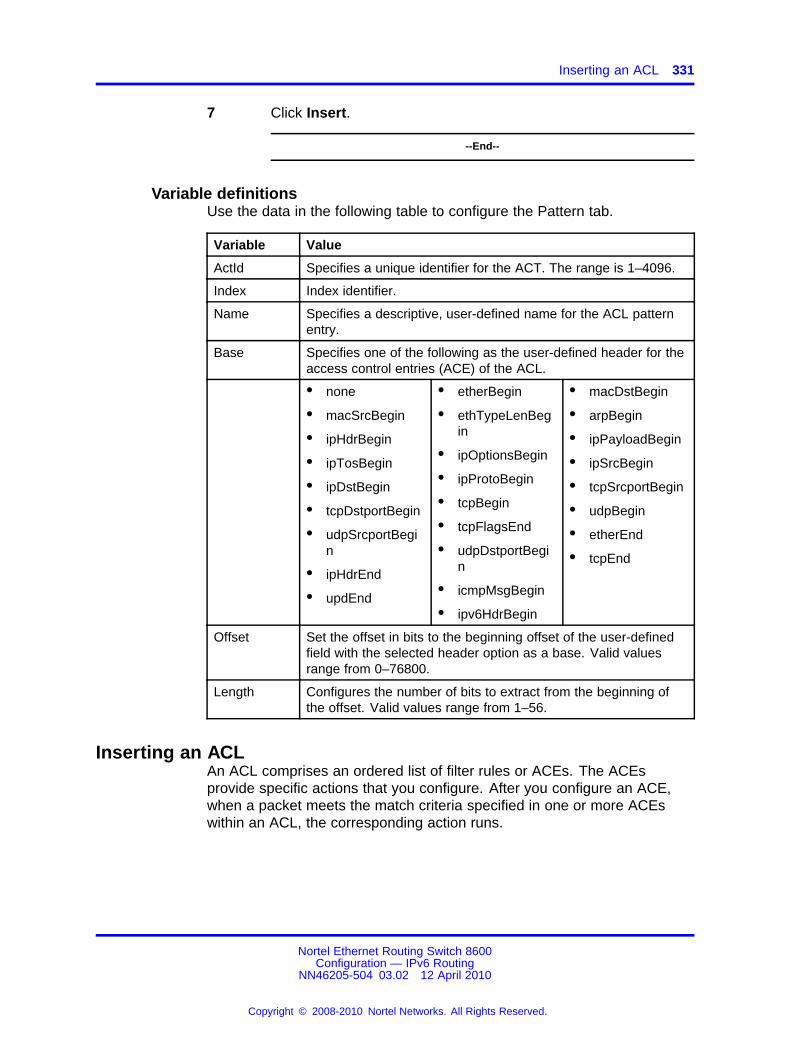
Inserting an ACL 331
7 Click Insert.
--End--
Variable definitionsUse the data in the following table to configure the Pattern tab.
Variable Value
ActId Specifies a unique identifier for the ACT. The range is 1–4096.
Index Index identifier.
Name Specifies a descriptive, user-defined name for the ACL patternentry.
Base Specifies one of the following as the user-defined header for theaccess control entries (ACE) of the ACL.
• none
• macSrcBegin
• ipHdrBegin
• ipTosBegin
• ipDstBegin
• tcpDstportBegin
• udpSrcportBegin
• ipHdrEnd
• updEnd
• etherBegin
• ethTypeLenBegin
• ipOptionsBegin
• ipProtoBegin
• tcpBegin
• tcpFlagsEnd
• udpDstportBegin
• icmpMsgBegin
• ipv6HdrBegin
• macDstBegin
• arpBegin
• ipPayloadBegin
• ipSrcBegin
• tcpSrcportBegin
• udpBegin
• etherEnd
• tcpEnd
Offset Set the offset in bits to the beginning offset of the user-definedfield with the selected header option as a base. Valid valuesrange from 0–76800.
Length Configures the number of bits to extract from the beginning ofthe offset. Valid values range from 1–56.
Inserting an ACLAn ACL comprises an ordered list of filter rules or ACEs. The ACEsprovide specific actions that you configure. After you configure an ACE,when a packet meets the match criteria specified in one or more ACEswithin an ACL, the corresponding action runs.
Nortel Ethernet Routing Switch 8600Configuration — IPv6 Routing
NN46205-504 03.02 12 April 2010
Copyright © 2008-2010 Nortel Networks. All Rights Reserved.
.

332 IPv6 traffic filter configuration using Enterprise Device Manager
ATTENTIONIf you configured any IPv6 attributes on the ACT, you must select IPv6 in thePktType field when you insert the ACL. If an ACT uses only Ethernet attributes,you can configure a single IPv4 ACL and a single IPv6 ACL.
Procedure steps
Step Action
1 In the navigation tree, open the following folders:Configuration,Security, Data Path.
2 Double-click Advanced Filters (ACE/ACLs).
3 Click the ACL tab.
4 Click Insert.
5 Type an ACL ID from 1 through 4096.
6 Select the act ID by clicking the ellipsis button (...).
7 Click OK.
8 Specify the ACL type.
9 Type a name for the ACL entry.
10 In the VlanList box, click the button and select the requiredentry.
11 In the PortList box, click the button and select the requiredentry.
12 Specify the DefaultAction and the GlobalAction.
13 Enable or disable the state.
14 In the PktType box, select the IPv6 option.
15 Click Insert.
--End--
Variable definitionsUse the data in the following table to configure the ACL.
Variable Value
AclId Specifies a unique identifier for the ACL entry inthe range 1–4096.
ActId Specifies a unique identifier for the ACT entry inthe range 1–4096.
Nortel Ethernet Routing Switch 8600Configuration — IPv6 Routing
NN46205-504 03.02 12 April 2010
Copyright © 2008-2010 Nortel Networks. All Rights Reserved.
.

Inserting an ACL 333
Variable Value
Type Specifies whether the ACL is VLAN or port-based.Valid options:
• inVlan
• outVlan
• inPort
• outPort
ATTENTIONThe inVlan and outVlan ACL types drop packetsif the VLAN is added after ACE creation. ForVLAN-based filters, ensure that the ACEconfiguration is set to all R or RS module slots,regardless of the VLAN port membership on aslot.
Name Specifies a descriptive user-defined name for theACL entry.
VlanList Identifies an array indicating all the VLANsassociated with the ACL entry. The value is usedonly with inVlan and outVlan ACL types.
PortList Specifies the ports added to the ACL entry. Thevalue is used only with inPort and outPort ACLtypes.
DefaultAction Specifies the action taken when no ACEs in theACL match. Valid options are deny and permit,with permit as the default.
GlobalAction Indicates the action applied to all ACEs that matchin an ACL:
• none
• mirror
• count
• mirror-count
ATTENTIONMirroring is not supported for egress filters in theNortel Ethernet Routing Switch 8600 Release 4.1software.
Nortel Ethernet Routing Switch 8600Configuration — IPv6 Routing
NN46205-504 03.02 12 April 2010
Copyright © 2008-2010 Nortel Networks. All Rights Reserved.
.

334 IPv6 traffic filter configuration using Enterprise Device Manager
Variable Value
State Enables or disables all of the ACEs in the ACL.The default value is enable.
PktType Specifies if the packet type is IPv4 or IPv6.
Modifying an ACLModify an ACL to change the configuration.
Procedure steps
Step Action
1 In the navigation tree, open the following folders:Configuration,Security, Data Path.
2 Double-click Advanced Filters (ACE/ACLs).
3 Click the ACL tab.
4 Double-click the field you want to change.
For example, if you double-click the GlobalAction field, you canselect from several options in the activated list.
5 Select the required option.
6 Click Applyto commit the required action.
--End--
Inserting ACE common entriesInsert access control entries (ACE) to add an ACE to an ACL.
Procedure steps
Step Action
1 In the navigation tree, open the following folders:Configuration,Security, Data Path.
2 Double-click Advanced Filters (ACE/ACLs).
3 Click the ACL tab.
4 Select the ACL to which to add an ACE.
5 Click the ACE button.
6 Click Insert.
7 Type data in the required fields.
Nortel Ethernet Routing Switch 8600Configuration — IPv6 Routing
NN46205-504 03.02 12 April 2010
Copyright © 2008-2010 Nortel Networks. All Rights Reserved.
.

Inserting ACE common entries 335
8 Click Insert.
--End--
Variable definitionsUse the data in the following table to configure the ACE.
Variable Value
AceId Specifies a unique identifier and priority for theACE.
Name Specifies a descriptive, user-defined namefor the ACE entry. The system automaticallyassigns a name if you do not choose one.
Mode Indicates the operating mode associated withthe ACE. Valid options are deny and permit,with none as the default.
MltIndex Specifies whether to override the MLT indexpicked by the MLT algorithm when a packetis sent on MLT ports. Valid values range 0–8,with 0 as the default.
RemarkDscp Specifies whether the Differentiated ServicesCode Point (DSCP) field value marks nonstandard traffic classes and local use Per HopBehavior (PHB). The default is disable.
RemarkDot1Priority Specifies whether Dot1 Priority as describedby Layer 2 standards, 802.1Q, and 802.1P isenabled. The default is disable.
Police Configures the desired policing profileidentifier. Valid values range from 0–16383,with zero (0) as the default. When policing isnot desired, you must configure the value tozero.
RedirectNextHop Redirects matching IP traffic to the next hop.
RedirectUnreach Configures the desired behavior for redirectedtraffic in case the specified next hop is notreachable. The default value is deny.
Nortel Ethernet Routing Switch 8600Configuration — IPv6 Routing
NN46205-504 03.02 12 April 2010
Copyright © 2008-2010 Nortel Networks. All Rights Reserved.
.

336 IPv6 traffic filter configuration using Enterprise Device Manager
Variable Value
EgressQueue Specifies the egress queue for 10/100 GbEmodule.
• If you specify only 1 value, then this valueis applied to the 1 Gb and 10 Gb queues aswell.
• If you specify 2 values, then the first valueis applied to the 10/100 module and thesecond value is applied to 1 Gb and 10 Gbmodules.
• If you specify all three values, then all threevalues apply respectively to the appropriateegress queue.
• If you specify a value greater than 8, itis not applied to the 10/100 GbE modulebecause it uses only 8 queues. However,the value is applied only to the 1 Gb and 10Gb module types. The default value is 64.
EgressQueue1g Specifies the egress queue for the 1 Gbmodule. The default value is 64.
EgressQueue10g Specifies the egress queue for the 10 Gbmodule. The default value is 64.
EgressQueueNNSC Identifies the configured ACE Nortel NetworksService Class (NNSC). The default is disable.
StopOnMatch Indicates whether to stop or continue if an ACEmatching the packet is found. When a matchoccurs, the switch does not attempt a matchon the other ACEs with a lower priority.
Flags Specifies one of the following flag values:
• none: Default value for the flags.
• count: Enables or disables counting if apacket matching the ACE is found.
• copyToPrimaryCp: Enables or disables thecopying of matching packets to the primaryCP.
• copyToSecondaryCp: Enables or disablesthe copying of matching packets to thesecondary CP.
• mirror: Enables or disables mirroring thematching packets to an interface. TheNortel Ethernet Routing Switch 8600mirrors one port or mirrors to one port.
Nortel Ethernet Routing Switch 8600Configuration — IPv6 Routing
NN46205-504 03.02 12 April 2010
Copyright © 2008-2010 Nortel Networks. All Rights Reserved.
.

Configuring a list of IPv6 source IP addresses for an ACE 337
Variable Value
IPfixState Enables or disables IP flow information export(IPfix).
RedirectNextHopIpv6 The IPv6 address to redirect the next hop.
Modifying ACE common entriesModify ACE common entries to change the current configuration.
ATTENTIONExcept the debug actions, disable the AdminState of the ACE before youperform any modifications.
Procedure steps
Step Action
1 In the navigation tree, open the following folders:Configuration,Security, Data Path.
2 Double-click Advanced Filters (ACE/ACLs).
3 Click the ACL tab.
4 Select the ACL.
5 Click the ACE button.
6 Double-click a field you want to change.
For example, if you double-click on the Mode field, you canselect from several options in the activated list.
7 Select the required option.
8 Click Applyto commit the action.
--End--
Configuring a list of IPv6 source IP addresses for an ACEConfigure an ACE IPv6 source address so that the filter looks for a specificIPv6 source address.
Prerequisites
• The associated ACL packet type must be IPv6.
• The associated ACT IPv6 attributes must be srcIpv6
Nortel Ethernet Routing Switch 8600Configuration — IPv6 Routing
NN46205-504 03.02 12 April 2010
Copyright © 2008-2010 Nortel Networks. All Rights Reserved.
.

338 IPv6 traffic filter configuration using Enterprise Device Manager
Procedure steps
Step Action
1 In the navigation tree, open the following folders:Configuration,Security, Data Path.
2 Double-click Advanced Filters (ACE/ACLs).
3 Click the ACL tab.
4 Select an IPv6 ACL.
5 Click ACE.
6 From the ACE Common tab, select an ACE.
7 ClickIPv6.
8 Click Insert.
9 Specify the operation (the only option is eq [equals]) and theIPv6 addresses.
10 Click Insert.
--End--
Variable definitionsUse the data in the following table to configure the Source Address tab.
Variable Value
AclId Specifies the ACL ID.
AceId Specifies the ACE ID.
Oper Specifies the ACE operation. The onlyoption is eq (equals).
List Specifies the IPv6 addresses—a binarystring of 16 octets in network byte-order.Enter a single IPv6 address, range of IPv6addresses, or multiple IPv6 addresses.
Configuring a list of IPv6 destination IP addresses for an ACEConfigure an ACE IPv6 destination address to have the filter look for aspecific IPv6 destination address.
Prerequisites
• The associated ACL packet type must be IPv6.
• The associated ACT IPv6 attributes must be dstIpv6.
Nortel Ethernet Routing Switch 8600Configuration — IPv6 Routing
NN46205-504 03.02 12 April 2010
Copyright © 2008-2010 Nortel Networks. All Rights Reserved.
.
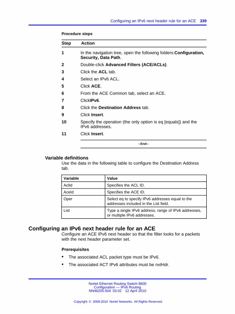
Configuring an IPv6 next header rule for an ACE 339
Procedure steps
Step Action
1 In the navigation tree, open the following folders:Configuration,Security, Data Path.
2 Double-click Advanced Filters (ACE/ACLs).
3 Click the ACL tab.
4 Select an IPv6 ACL.
5 Click ACE.
6 From the ACE Common tab, select an ACE.
7 ClickIPv6.
8 Click the Destination Address tab.
9 Click Insert.
10 Specify the operation (the only option is eq [equals]) and theIPv6 addresses.
11 Click Insert.
--End--
Variable definitionsUse the data in the following table to configure the Destination Addresstab.
Variable Value
AclId Specifies the ACL ID.
AceId Specifies the ACE ID.
Oper Select eq to specify IPv6 addresses equal to theaddresses included in the List field.
List Type a single IPv6 address, range of IPv6 addresses,or multiple IPv6 addresses.
Configuring an IPv6 next header rule for an ACEConfigure an ACE IPv6 next header so that the filter looks for a packetswith the next header parameter set.
Prerequisites
• The associated ACL packet type must be IPv6.
• The associated ACT IPv6 attributes must be nxtHdr.
Nortel Ethernet Routing Switch 8600Configuration — IPv6 Routing
NN46205-504 03.02 12 April 2010
Copyright © 2008-2010 Nortel Networks. All Rights Reserved.
.

340 IPv6 traffic filter configuration using Enterprise Device Manager
Procedure steps
Step Action
1 In the navigation tree, open the following folders:Configuration,Security, Data Path.
2 Double-click Advanced Filters (ACE/ACLs).
3 Click the ACL tab.
The ACL box appears with the ACL tab displayed.
4 Select an IPv6 ACL.
5 Click ACE.
6 Select an ACE.
7 ClickIPv6.
8 Click the Next Hdr tab.
9 Click Insert.
10 Specify the operation and the Next header parameters.
11 Click Insert.
--End--
Variable definitionsUse the data in the following table to configure the next header rule.
Variable Value
AclId Specifies the ACL ID.
AceId Specifies the ACE ID.
Oper Specifies the ACE operation. The optionsare eq (equal) or ne (not equal).
NxtHdr Specifies the next header. .
Deleting an ACTDelete an ACT to remove it from the configuration.
ATTENTIONYou cannot delete or modify an ACT associated with ACLS.
Procedure steps
Nortel Ethernet Routing Switch 8600Configuration — IPv6 Routing
NN46205-504 03.02 12 April 2010
Copyright © 2008-2010 Nortel Networks. All Rights Reserved.
.

Deleting ACE common entries 341
Step Action
1 In the navigation tree, open the following folders:Configuration,Security, Data Path.
2 Double-click Advanced Filters (ACE/ACLs).
3 Select the ActId or name of the ACT to delete.
4 Click Delete.
--End--
Deleting an ACLDelete an ACL to remove it from the configuration.
Procedure steps
Step Action
1 In the navigation tree, open the following folders:Configuration,Security, Data Path.
2 Double-click Advanced Filters (ACE/ACLs).
3 Click the ACL tab.
4 Select the ACL to delete.
5 Click Delete to remove the selected ACL.
A dialog box prompts you to confirm the deletion.
6 Click Yes to delete the ACL.
--End--
Deleting ACE common entriesDelete ACE common entries to remove them from the configuration.
Procedure steps
Step Action
1 In the navigation tree, open the following folders:Configuration,Security, Data Path.
2 Double-click Advanced Filters (ACE/ACLs).
3 Click the ACL tab.
4 Select the ACL.
Nortel Ethernet Routing Switch 8600Configuration — IPv6 Routing
NN46205-504 03.02 12 April 2010
Copyright © 2008-2010 Nortel Networks. All Rights Reserved.
.

342 IPv6 traffic filter configuration using Enterprise Device Manager
5 Click the ACE button.
6 Select the name of the ACE common entry to delete.
7 Click Delete to remove the selected entry.
--End--
Nortel Ethernet Routing Switch 8600Configuration — IPv6 Routing
NN46205-504 03.02 12 April 2010
Copyright © 2008-2010 Nortel Networks. All Rights Reserved.
.

343.
IPv6 traffic filter configuration usingthe CLI
This chapter describes how to block unwanted traffic from entering aswitch or to prioritize desired traffic. Traffic filters instruct an interface toselectively handle specified traffic. The switch determines which packetsreceive special handling based on information in the packet headers.
Using traffic filters, you can reduce network congestion and control accessto network resources by blocking, forwarding, or prioritizing specified trafficon an interface. You can apply multiple traffic filters to a single interface.
For conceptual information about traffic filtering, see “IPv6 routingfundamentals” (page 25).
For additional information about filters, see Nortel Ethernet RoutingSwitch 8600 Configuration — QoS and IP Filtering for R and RS Modules(NN46205-507) .
IPv6 traffic filter configuration navigation• “Job aid: Roadmap of traffic filter CLI commands” (page 344)
• “Configuring ACTs” (page 345)
• “Creating a template for user-created patterns” (page 347)
• “Applying the ACT” (page 349)
• “Configuring ACLs” (page 349)
• “Configuring global and default actions for an ACL” (page 350)
• “Associating VLANs for an ACL” (page 351)
• “Associating ports for an ACL” (page 352)
• “Adding an ACE with IPv6 header attributes” (page 352)
Nortel Ethernet Routing Switch 8600Configuration — IPv6 Routing
NN46205-504 03.02 12 April 2010
Copyright © 2008-2010 Nortel Networks. All Rights Reserved.
.

344 IPv6 traffic filter configuration using the CLI
Job aid: Roadmap of traffic filter CLI commandsThe following table lists the commands and parameters that you use toperform the procedures in this chapter.
Table 29Job aid: Roadmap of traffic filter CLI commands
Command Parameter
create <type> act <value> [pktType]<value> [name <value>]
delete
enable
disable
name <value>
config filter acl <acl-id>
info
create [name <value>]
delete
enable
disable
name <value>
config filter acl <acl-id> ace<ace-id>
info
custom-filter1<pattern1-name><ace-op><value>
custom-filter2<pattern2-name><ace-op><value>
custom-filter3<pattern3-name><ace-op><value>
config filter acl <acl-id> ace<ace-id> advanced
delete
delete <ipv6-attributes>
dst-ipv6 <ace-op> <dst-ipv6-list>
info
src-ipv6 <ace-op> <src-ipv6-list>
config filter acl <acl-id> ace<ace-id> ipv6
nxt-hdr <ace-op> <nxt-hdr>
add <ports>
remove <ports>
config filter acl <acl-id> port
info
default-action <value>
global-action <value>
config filter acl <acl-id> set
info
Nortel Ethernet Routing Switch 8600Configuration — IPv6 Routing
NN46205-504 03.02 12 April 2010
Copyright © 2008-2010 Nortel Networks. All Rights Reserved.
.

Configuring ACTs 345
Table 29Job aid: Roadmap of traffic filter CLI commands (cont’d.)
Command Parameter
add <vid> [<vid2-vid3>]
remove <vid> [<vid2-vid3>]
config filter acl <acl-id> vlan
info
create [name <value>]
delete
apply
name <value>
info
arp <arp-attributes>
ip <ip-attributes>
ipv6 <ipv6-attributes>
ethernet <ethernet-attributes>
config filter act <act-id>
protocol <protocol-attributes>
add <base> <offset> <length>
name <pattern-name>
config filter act <act-id> pattern<pattern-name>
info
Configuring ACTsConfigure an access control template (ACT) to create, delete, apply,and specify attributes. After you apply the ACT you cannot change theattributes. ACT IDs 4001 to 4096 are reserved for system-defined ACTs.
System-defined ACTs are available for filters as required.
ATTENTIONAn ACT can use IPv4 or IPv6 attributes, but not both. You cannot combine IPv4and IPv6 attributes in the same ACL.
Procedure steps
Step Action
1 Configure an ACT by using the following command:
config filter act <act-id>
--End--
Nortel Ethernet Routing Switch 8600Configuration — IPv6 Routing
NN46205-504 03.02 12 April 2010
Copyright © 2008-2010 Nortel Networks. All Rights Reserved.
.
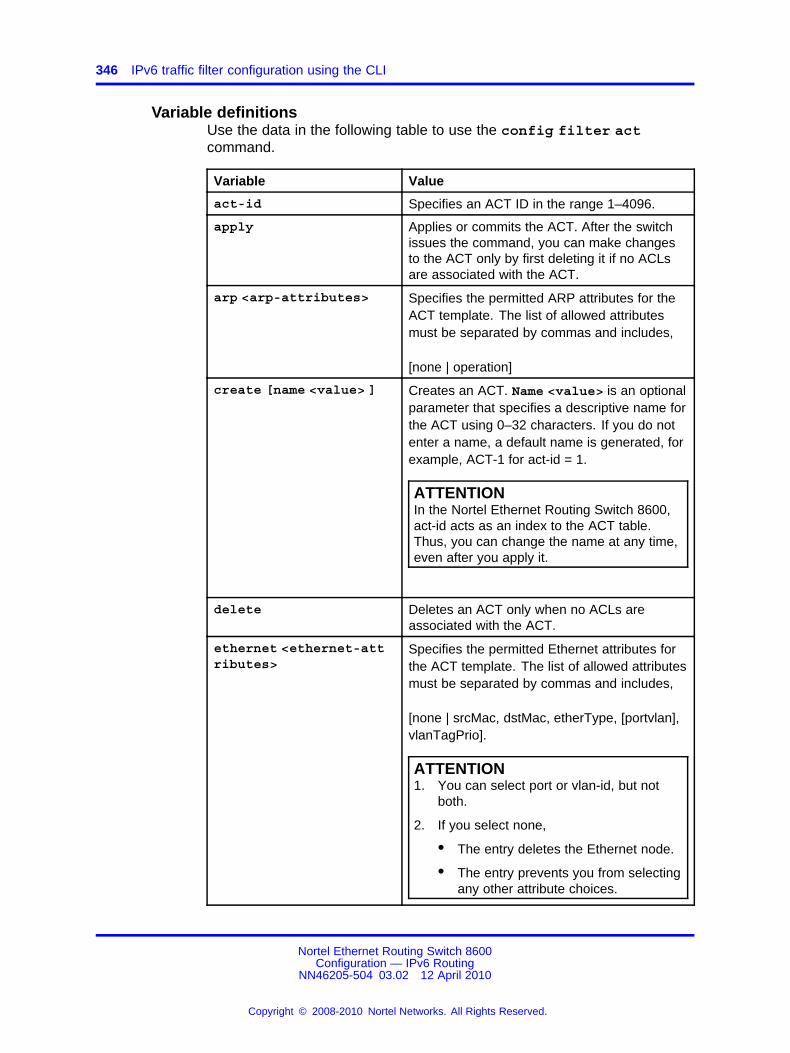
346 IPv6 traffic filter configuration using the CLI
Variable definitionsUse the data in the following table to use the config filter actcommand.
Variable Value
act-id Specifies an ACT ID in the range 1–4096.
apply Applies or commits the ACT. After the switchissues the command, you can make changesto the ACT only by first deleting it if no ACLsare associated with the ACT.
arp <arp-attributes> Specifies the permitted ARP attributes for theACT template. The list of allowed attributesmust be separated by commas and includes,
[none | operation]
create [name <value> ] Creates an ACT. Name <value> is an optionalparameter that specifies a descriptive name forthe ACT using 0–32 characters. If you do notenter a name, a default name is generated, forexample, ACT-1 for act-id = 1.
ATTENTIONIn the Nortel Ethernet Routing Switch 8600,act-id acts as an index to the ACT table.Thus, you can change the name at any time,even after you apply it.
delete Deletes an ACT only when no ACLs areassociated with the ACT.
ethernet <ethernet-attributes>
Specifies the permitted Ethernet attributes forthe ACT template. The list of allowed attributesmust be separated by commas and includes,
[none | srcMac, dstMac, etherType, [portvlan],vlanTagPrio].
ATTENTION1. You can select port or vlan-id, but not
both.
2. If you select none,
• The entry deletes the Ethernet node.
• The entry prevents you from selectingany other attribute choices.
Nortel Ethernet Routing Switch 8600Configuration — IPv6 Routing
NN46205-504 03.02 12 April 2010
Copyright © 2008-2010 Nortel Networks. All Rights Reserved.
.

Creating a template for user-created patterns 347
Variable Value
info Information about the ACTs that you created.
ip <ip-attributes> Specifies the permitted IP attributes for theACT template. The list of allowed attributesmust be separated by commas and includes,
[none | srcIp, dstIp, ipFragFlag, ipOptions,ipProtoType, dscp].
ipv6 <ipv6-attributes> Specifies the permitted IPv6 for the ACTtemplate. The list of allowed attributes must beseparated by commas and includes,
[none | srcIpv6, dstIpv6, nextHdr]
name <value> Specifies a name for the ACT. <value> is anoptional parameter that specifies a name forthe ACT using 0–32 characters.
protocol <protocol-attributes>
Specifies the permitted protocol attributes forthe ACT template. The list of allowed attributesmust be separated by commas and includes,
[none | tcpSrcPort, udpSrcPort, tcpDstPort,udpDstPort, tcpFlags, icmpMsgFlags]
Creating a template for user-created patternsCreate a template for patterns within an ACT. You can associate amaximum of three patterns with an ACT.
Procedure steps
Step Action
1 Create a template by using the following command:
config filter act <act-id> pattern <pattern-name>
--End--
Variable definitionsUse the data in the following table to use the config filter actpattern command.
Nortel Ethernet Routing Switch 8600Configuration — IPv6 Routing
NN46205-504 03.02 12 April 2010
Copyright © 2008-2010 Nortel Networks. All Rights Reserved.
.

348 IPv6 traffic filter configuration using the CLI
Variable Value
act-id Specifies an ACT ID in the range of 1–4096.
add <base><offset> <length>
Adds a template for patterns you create. Optionsinclude:
• base: the base and the offset together determinethe beginning of the pattern. Permitted values forthe base include the following:
— ether-begin
— mac-dst-begin
— mac-src-begin
— ethTypeLen-begin
— arp-begin
— ip-hdr-begin
— ip-options-begin
— ip-payload-begin
— ip-tos-begin
— ip-proto-begin
— ip-src-begin
— ip-dst-begin
— ipv6-hdr-begin
— tcp-begin
— tcp-srcport-begin
— tcp-dstport-begin
— tcp-flags-end
— udp-begin
— udp-srcport-begin
— udp-dstport-begin
— ether-end
— ip-hdr-end
— icmp-msg-begin
— tcp-end
— udp-end
• offset: the number of bits from the base where thepattern starts.
• length: the length in bits of the user-defined fieldfrom 1–56.
Nortel Ethernet Routing Switch 8600Configuration — IPv6 Routing
NN46205-504 03.02 12 April 2010
Copyright © 2008-2010 Nortel Networks. All Rights Reserved.
.

Configuring ACLs 349
Variable Value
info Displays information about the template patterns youcreated under an ACT.
name <pattern-name>
Renames the pattern with a new name that you define.Each of the three patterns must use a unique name.
pattername Specifies a pattern name with a range 0–32 characters.
Applying the ACTAfter you create and configure the ACT, apply it to implement theconfiguration.
Procedure steps
Step Action
1 Apply the ACT by using the following command:
configure filter act <act id> apply
--End--
Configuring ACLsConfigure access control lists (ACL) to create lists of rules for the ACT.
ATTENTIONIf the ACT contains IPv6 attributes, you must configure an ACL of pktType IPv6.If the ACT uses only Ethernet attributes, you can configure one ACL of pktTypeIPv4 and an ACL of pktType IPv6.
Procedure steps
Step Action
1 Configure an ACL by using the following command:
config filter acl <acl-id>
--End--
Variable definitionsUse the data in the following table to use the config filter aclcommand.
Variable Value
acl-id Specifies an ACL ID in the range 1–4096.
Nortel Ethernet Routing Switch 8600Configuration — IPv6 Routing
NN46205-504 03.02 12 April 2010
Copyright © 2008-2010 Nortel Networks. All Rights Reserved.
.

350 IPv6 traffic filter configuration using the CLI
Variable Value
create <type> act<value> [pktType]<value> [name <value> ]
Creates an access control list (ACL) only whenan ACT is associated with that ACL:
• <type>: type of ACL, including [InVlan |outVlan | InPort | outPort].
• act <value>: an ACT template ID in therange from 1–4096.
• pktType <value>: ipv4 or ipv6
• name <value>: an optional parameter thatspecifies a descriptive name for the ACLusing 0–31 characters. If you do not enter aname when you create the ACL, a defaultname is generated, for example, ACL-2 foracl-id = 2
ATTENTIONThe pktType field is optional for IPv4 trafficfilters. It is required if you apply the ACL toIPv6 packets.
delete Deletes an ACL.
ATTENTIONThis command removes all VLANs or brouterports under this ACL and deletes all ACEs.The command does not delete the ACTs.
disable Disables the ACL state along with all of theACEs below it. The default value is disable.
enable Enables the ACL state along with all of theACEs below it.
Enable is the default state for the ACL.
info Displays information about the ACL.
name <value> Renames an ACL.
Configuring global and default actions for an ACLConfigure global and default actions for an ACL to apply the configurationglobally.
Nortel Ethernet Routing Switch 8600Configuration — IPv6 Routing
NN46205-504 03.02 12 April 2010
Copyright © 2008-2010 Nortel Networks. All Rights Reserved.
.

Associating VLANs for an ACL 351
Procedure steps
Step Action
1 Configure global and default actions by using the followingcommand:
config filter acl <acl-id> set
--End--
Variable definitionsUse the data in the following table to use the config filter acl setcommand.
Variable Value
acl-id Specifies an ACL ID in the range of 1–4096.
default-action <value> Specifies the default action when no ACEsmatch. Permitted options include [deny |permit], with a default of permit.
global-action <value> Specifies the global action for the matchingACEs. Permitted options include [none | mirror| count | mirror-count|ipfix|mirror-ipfix|count-ipfix|mirror-count-ipfix]. The default is none.
info Displays the status of the global and defaultactions.
Associating VLANs for an ACLAssociate or remove VLANs for a particular ACL.
Procedure steps
Step Action
1 Associate or remove VLANs by using the following command:
config filter acl <acl-id> vlan
--End--
Variable definitionsUse the data in the following table to use the config filter acl vlancommand.
Variable Value
acl-id Specifies an ACL ID in the range of 1–4096.
Nortel Ethernet Routing Switch 8600Configuration — IPv6 Routing
NN46205-504 03.02 12 April 2010
Copyright © 2008-2010 Nortel Networks. All Rights Reserved.
.

352 IPv6 traffic filter configuration using the CLI
Variable Value
add <vid> [ <vid2-vid3>] Associates a VLAN or a VLAN list with aparticular ACL. <vid> is a list of VLANsseparated by a comma or a range of VLANsspecified as low-high [vlan-id -vlan-id].
info Displays the ACL VLAN status.
remove <vid> [<vid2-vid3> ]
Removes a VLAN or VLAN list from aparticular ACL. <vid> is a list of VLANsseparated by a comma or a range of VLANsspecified as low-high [vlan-id -vlan-id].
Associating ports for an ACLAssociate or remove ports for a particular ACL.
Procedure steps
Step Action
1 Associate or remove ports by using the following command:
config filter acl <acl-id> port
--End--
Variable definitionsUse the data in the following table to use the config filter acl portcommand.
Variable Value
acl-id Specifies an ACL ID in the range 1–4096.
add <ports> ] Associates a port or a port list with a particularACL. <ports> is a list of ports separatedby a comma or a range of ports specified aslow-high [slot/port-slot/port].
info Displays the ACL port status.
remove <ports> Removes a port or a port list from a particularACL. <ports> is a list of ports separatedby a comma or a range of ports specified aslow-high [slot/port-slot/port].
Adding an ACE with IPv6 header attributesAdd an ACE with IP header attributes as match criteria.
Nortel Ethernet Routing Switch 8600Configuration — IPv6 Routing
NN46205-504 03.02 12 April 2010
Copyright © 2008-2010 Nortel Networks. All Rights Reserved.
.

Adding an ACE with IPv6 header attributes 353
ATTENTIONBe aware of the following:
• You cannot select (*) after <ace-op>.
• If you select no entry, You delete the Ethernet, ARP, or IPv6 protocol node.
Procedure steps
Step Action
1 Add an ACE with IPv6 header attributes by using the followingcommand:
config filter acl <acl-id> ace <ace-id> ipv6
--End--
Variable definitionsUse the data in the following table to use the config filter acl aceipv6 command.
Variable Value
ace-id Specifies an ACE ID in the range 1–1000.
acl-id Specifies an ACL ID in the range 1–4096.
delete <ipv6-attributes>
Deletes the specified IPv6 ACE attributes.
dst-ipv6 <ace-op><dst-ipv6-list>
Specifies the following:
• an operator for a field match condition (eq)
• the list of destination IPv6 addressesseparated by commas
info Displays the current level parameter settingand the next level directories.
nxt-hdr <ace-op><nxt-hdr>
Specifies the following:
• an operator for a field match condition (eq| ne)
• the next header value
src-ipv6 <ace-op><src-ipv6-list>
Specifies the following:
• an operator for a field match condition (eq)
• the list of source IPv6 addresses separatedby commas
Nortel Ethernet Routing Switch 8600Configuration — IPv6 Routing
NN46205-504 03.02 12 April 2010
Copyright © 2008-2010 Nortel Networks. All Rights Reserved.
.

354 IPv6 traffic filter configuration using the CLI
Nortel Ethernet Routing Switch 8600Configuration — IPv6 Routing
NN46205-504 03.02 12 April 2010
Copyright © 2008-2010 Nortel Networks. All Rights Reserved.
.

355.
IPv6 traffic filter configuration usingthe NNCLI
This chapter describes how to block unwanted traffic from entering aswitch or to prioritize desired traffic. Traffic filters instruct an interface toselectively handle specified traffic. The switch determines which packetsreceive special handling based on information in the packet headers.
Using traffic filters, you can reduce network congestion and control accessto network resources by blocking, forwarding, or prioritizing specified trafficon an interface. You can apply multiple traffic filters to a single interface.
For conceptual information about traffic filtering, see “IPv6 routingfundamentals” (page 25).
For additional information about filters, see Nortel Ethernet RoutingSwitch 8600 Configuration — QoS and IP Filtering for R and RS Modules(NN46205-507).
IPv6 traffic filter configuration navigation• “Job aid: Roadmap of traffic filter NNCLI commands” (page 356)
• “Configuring ACTs” (page 356)
• “Creating a template for user-created patterns” (page 358)
• “Applying the ACT” (page 360)
• “Configuring ACLs” (page 360)
• “Configuring global and default actions for an ACL” (page 362)
• “Associating VLANs for an ACL” (page 362)
• “Associating ports for an ACL” (page 363)
• “Adding an ACE with IPv6 header attributes” (page 364)
Nortel Ethernet Routing Switch 8600Configuration — IPv6 Routing
NN46205-504 03.02 12 April 2010
Copyright © 2008-2010 Nortel Networks. All Rights Reserved.
.

356 IPv6 traffic filter configuration using the NNCLI
Job aid: Roadmap of traffic filter NNCLI commandsThe following table lists the commands and parameters that you use toperform the procedures in this chapter.
Table 30Job aid: Roadmap of traffic filter NNCLI commands
Command Parameter
Privileged EXEC mode
filter apply act <act-id> –
Global Configuration mode
enable
name <word>
type <inVlan|outVlan|inPort|outPort>
act <act-id>
filter acl <acl-id>
pktType <ipv4|ipv6>
dst-ipv6 eq <word>
nxt-hdr <eq|ne> <next-header>
filter acl ace ipv6 <acl-id> <ace-id>
src-ipv6 eq <word>
filter acl port <acl-id> <port> –
default-action <value>filter acl set <acl-id>
global-action <value>
filter acl vlan <acl-id> <vlan-id> –
arp <operation>
ethernet <word>
ip <word>
ipv6 <word>
name <word>
filter act <act-id>
protocol <word>
<word>
<base> <offset> <length>
filter act pattern <act-id>
name <pattern-name>
Configuring ACTsConfigure an access control template (ACT) to create, delete, apply,and specify attributes. After you apply the ACT you cannot change theattributes. ACT IDs 4001 to 4096 are reserved for system-defined ACTs.
Nortel Ethernet Routing Switch 8600Configuration — IPv6 Routing
NN46205-504 03.02 12 April 2010
Copyright © 2008-2010 Nortel Networks. All Rights Reserved.
.

Configuring ACTs 357
System-defined ACTs are available for filters as required.
ATTENTIONAn ACT can use IPv4 or IPv6 attributes, but not both. You cannot combine IPv4and IPv6 attributes in the same ACL.
Prerequisites
• You must log on to the Global Configuration mode in the NNCLI.
Procedure steps
Step Action
1 Create an ACT by assigning it an ID by using the followingcommand:
filter act <act-id>
2 Configure parameters for the ACT by using the followingcommand:
filter act <act-id> [arp <operation>] [ethernet <word>][ip <word>] [ipv6 <word>] [name <word>] [protocol<word>]
--End--
Variable definitionsUse the data in the following table to use the filter act command.
Variable Value
act-id Specifies an ACT ID in the range 1–4096.
ATTENTIONIn the Nortel Ethernet Routing Switch 8600,act-id is an index to the ACT table. Thus, youcan change the name at any time, even afteryou apply it.
To configure this option to the default value,use the default operator with the command.
arp <operation> Specifies the permitted ARP attributes for theACT template. The list of allowed attributesmust be separated by commas and includes:
[operation]
Nortel Ethernet Routing Switch 8600Configuration — IPv6 Routing
NN46205-504 03.02 12 April 2010
Copyright © 2008-2010 Nortel Networks. All Rights Reserved.
.

358 IPv6 traffic filter configuration using the NNCLI
Variable Value
ethernet <word> Specifies the permitted Ethernet attributes forthe ACT template. The list of allowed attributesmust be separated by commas and includes:
[none | srcMac, dstMac, etherType, [portvlan],vlanTagPrio].
ATTENTION1. You can select port or vlan-id, but not
both.
2. If you select none:
• The entry deletes the Ethernet node.
• The entry prevents you from selectingany other attribute choices.
ip <word> Specifies the permitted IP attributes for theACT template. The list of allowed attributesmust be separated by commas and includes:
[none | srcIp, dstIp, ipFragFlag, ipOptions,ipProtoType, dscp].
ipv6 <word> Specifies the permitted IPv6 for the ACTtemplate. The list of allowed attributes must beseparated by commas and includes:
[none | srcIpv6, dstIpv6, nextHdr]
name <word> Specifies a name for the ACT. <word> is anoptional parameter that specifies a name forthe ACT using 0–32 characters. If you do notenter a name, a default name is generated, forexample, ACT-1 for act-id = 1.
protocol <word> Specifies the permitted protocol attributes forthe ACT template. The list of allowed attributesmust be separated by commas and includes:
[none | tcpSrcPort, udpSrcPort, tcpDstPort,udpDstPort, tcpFlags, icmpMsgFlags]
Creating a template for user-created patternsCeate a template for patterns within an ACT. You can associate amaximum of three patterns with an ACT.
Nortel Ethernet Routing Switch 8600Configuration — IPv6 Routing
NN46205-504 03.02 12 April 2010
Copyright © 2008-2010 Nortel Networks. All Rights Reserved.
.

Creating a template for user-created patterns 359
Prerequisites
• You must log on to the Global Configuration mode in the NNCLI.
Procedure steps
Step Action
1 Create a template by using the following command:
filter act pattern <act-id> <word> <base> <offset><length>
--End--
Variable definitionsUse the data in the following table to use the filter act patterncommand.
Variable Value
act-id Specifies an ACT ID in the range of 1–4096.
<base> <offset><length>
Adds a template for patterns you create:
• base: the base and the offset together determinethe beginning of the pattern. Permitted values forthe base include the following:
— ether-begin
— mac-dst-begin
— mac-src-begin
— ethTypeLen-begin
— arp-begin
— ip-hdr-begin
— ip-options-begin
— ip-payload-begin
— ip-tos-begin
— ip-proto-begin
— ip-src-begin
— ip-dst-begin
— ipv6-hdr-begin
— tcp-begin
— tcp-srcport-begin
Nortel Ethernet Routing Switch 8600Configuration — IPv6 Routing
NN46205-504 03.02 12 April 2010
Copyright © 2008-2010 Nortel Networks. All Rights Reserved.
.

360 IPv6 traffic filter configuration using the NNCLI
Variable Value
— tcp-dstport-begin
— tcp-flags-end
— udp-begin
— udp-srcport-begin
— udp-dstport-begin
— ether-end
— ip-hdr-end
— icmp-msg-begin
— tcp-end
— udp-end
• offset: the number of bits from the base where thepattern starts. This is a range from 0–76800.
• length: the length in bits of the user-defined fieldfrom 1–56.
name <pattern-name>
Renames the pattern with a new name that you define.Each of the three patterns must have a unique name.
word Specifies a name for the pattern in the range of 1–32characters. To set this option to the default value, usethe default operator with the command.
Applying the ACTAfter you create and configure the ACT, apply it to implement theconfiguration.
Prerequisites
• You must log on to the Privileged EXEC mode in the NNCLI.
Procedure steps
Step Action
1 Apply the ACT by using the following command:
filter apply act <act-id>
--End--
Configuring ACLsConfigure access control lists (ACL) to create rules for the ACT.
Nortel Ethernet Routing Switch 8600Configuration — IPv6 Routing
NN46205-504 03.02 12 April 2010
Copyright © 2008-2010 Nortel Networks. All Rights Reserved.
.

Configuring ACLs 361
ATTENTIONIf an ACT contains IPv6 attributes, you must configure an ACL of pktType IPv6.If the ACT uses only Ethernet attributes, you can configure one ACL of pktTypeIPv4 and an ACL of pktType IPv6.
Prerequisites
• You must log on to the Global Configuration mode in the NNCLI.
Procedure steps
Step Action
1 Configure an ACL by using the following command:
filter acl <acl-id> type <inVlan|outVlan|inPort|outPort> act <act-id> pktType <ipv4|ipv6> name <word>
2 Enable an ACL by using the following command:
filter acl <acl-id> enable
--End--
Variable definitionsUse the data in the following table to use the filter acl command.
Variable Value
acl-id Specifies an ACL ID in the range 1–4096.
act <act-id> Specifies the ACT ID to associate with theACL.
enable Enables the ACL state along with all ACEsbelow it.
Enable is the default state for the ACL.
name <word> Renames an ACL. To configure this option tothe default value, use the default operatorwith the command.
pktType <ipv4|ipv6> Configures the packet type for the ACL.
ATTENTIONThe pktType field is optional for IPv4 trafficfilters. It is required if you apply the ACL toIPv6 packets.
type <inVlan|outVlan|inPort|outPort>
Configures the type of ACL.
Nortel Ethernet Routing Switch 8600Configuration — IPv6 Routing
NN46205-504 03.02 12 April 2010
Copyright © 2008-2010 Nortel Networks. All Rights Reserved.
.

362 IPv6 traffic filter configuration using the NNCLI
Configuring global and default actions for an ACLConfigure global and default actions for an ACL to globally apply theconfiguration.
Prerequisites
• You must log on to the Global Configuration mode in the NNCLI.
Procedure steps
Step Action
1 Configure default actions by using the following command:
filter acl set <acl-id> default-action <value>
2 Configure global actions by using the following command:
filter acl set <acl-id> global-action <value>
--End--
Variable definitionsUse the data in the following table to use the filter acl set command.
Variable Value
acl-id Specifies an ACL ID in the range of 1–4096.
default-action <value> Specifies the default action when no ACEsmatch. Permitted options include [deny|permit],with a default of permit. To configure thisoption to the default value, use the defaultoperator with the command.
global-action <value> Specifies the global action for thematching ACEs. Permitted options include[none|count|count-ipfix|ipfix|mirror|mirror-count|mirror-count-ipfix|mirror-ipfix]. The defaultis none. To configure this option to the defaultvalue, use the default operator with thecommand.
Associating VLANs for an ACLAssociate or remove VLANs for a an ACL.
Prerequisites
• You must log on to the Global Configuration mode in the NNCLI.
Nortel Ethernet Routing Switch 8600Configuration — IPv6 Routing
NN46205-504 03.02 12 April 2010
Copyright © 2008-2010 Nortel Networks. All Rights Reserved.
.

Associating ports for an ACL 363
Procedure steps
Step Action
1 Associate or remove VLANs by using the following command:
filter acl vlan <acl-id> <vlan-id>
--End--
Variable definitionsUse the data in the following table to use the filter acl vlancommand.
Variable Value
acl-id Specifies an ACL ID in the range of 1–4096.To configure this option to the default value,use the default operator with the command.
vlan-id Associates a VLAN or a VLAN list witha particular ACL. Format a list of VLANsseparated by a comma or a range of VLANsspecified as low-high [vlan-id -vlan-id]. Toconfigure this option to the default value, usethe default operator with the command.
Associating ports for an ACLAssociate or remove ports for an ACL.
Prerequisites
• You must log on to the Global Configuration mode in the NNCLI.
Procedure steps
Step Action
1 Associate or remove ports by using the following command:
filter acl port <acl-id> <port>
--End--
Variable definitionsUse the data in the following table to use the filter acl portcommand.
Nortel Ethernet Routing Switch 8600Configuration — IPv6 Routing
NN46205-504 03.02 12 April 2010
Copyright © 2008-2010 Nortel Networks. All Rights Reserved.
.

364 IPv6 traffic filter configuration using the NNCLI
Variable Value
acl-id Specifies an ACL ID in the range 1–4096.
port Associates a port or a port list with a particularACL. Format a list of ports separated bya comma or a range of ports specified aslow-high [slot/port -slot/port].
Adding an ACE with IPv6 header attributesAdd an ACE with IP header attributes as match criteria.
ATTENTIONBe aware of the following:
• You cannot select (*) after <ace-op>.
• If you select no entry, it indicates that you want to delete the respectiveEthernet, ARP, or IPv6 protocol node.
Prerequisites
• You must log on to the Global Configuration mode in the NNCLI.
Procedure steps
Step Action
1 Add an ACE with IPv6 header attributes by using the followingcommand:
filter acl ace ipv6 <acl-id> <ace-id> [dst-ipv6 eq<word>] [nxt-hdr <eq|ne> <next-header>] [src-ipv6 eq<word>]
--End--
Variable definitionsUse the data in the following table to use the filter acl ace ipv6command.
Variable Value
ace-id Specifies an ACE ID in the range 1–1000. Toconfigure this option to the default value, usethe default operator with the command.
acl-id Specifies an ACL ID in the range 1–4096. Toconfigure this option to the default value, usethe default operator with the command.
Nortel Ethernet Routing Switch 8600Configuration — IPv6 Routing
NN46205-504 03.02 12 April 2010
Copyright © 2008-2010 Nortel Networks. All Rights Reserved.
.

Adding an ACE with IPv6 header attributes 365
Variable Value
dst-ipv6 eq <word> Specifies the following:
• an operator for a field match condition—eq
• the list of destination IPv6 addressesseparated by commas
nxt-hdr <eq|ne><nxt-hdr>
Specifies the following:
• an operator for a field match condition (eq| ne)
• the next header value from one of thefollowing: fragment|hop-by-hop|icmpv6|ipsecah|ipsecesp|noHdr|routing|tcp|udp|undefined
src-ipv6 eq <word> Specifies the following:
• an operator for a field match condition—eq
• the list of source IPv6 addresses separatedby commas
Nortel Ethernet Routing Switch 8600Configuration — IPv6 Routing
NN46205-504 03.02 12 April 2010
Copyright © 2008-2010 Nortel Networks. All Rights Reserved.
.

366 IPv6 traffic filter configuration using the NNCLI
Nortel Ethernet Routing Switch 8600Configuration — IPv6 Routing
NN46205-504 03.02 12 April 2010
Copyright © 2008-2010 Nortel Networks. All Rights Reserved.
.

367.
InteroperabilityThe Nortel Ethernet Routing Switch 8600 provides interoperability withservers running Linux and Windows XP. This chapter provides basicconfiguration and verification procedures for the various systems.
Interoperability navigation• “Enabling IPv6 in Windows XP” (page 367)
• “Pinging the switch from a Windows XP system” (page 367)
• “Enabling IPv6 in Linux” (page 368)
• “Pinging the Linux system from the switch” (page 369)
• “Pinging the Nortel Ethernet Routing Switch 8600 from the Linuxsystem” (page 369)
• “Assigning IPv6 addresses to the Linux system” (page 370)
• “Viewing IPv6 neighbors from the Linux system” (page 370)
Enabling IPv6 in Windows XPEnable IPv6 to add IPv6 functionality on the Windows XP system.
Procedure steps
Step Action
1 Open the command prompt.
2 At the prompt, enter ipv6 install.
--End--
Pinging the switch from a Windows XP systemPing the switch to test connectivity.
Nortel Ethernet Routing Switch 8600Configuration — IPv6 Routing
NN46205-504 03.02 12 April 2010
Copyright © 2008-2010 Nortel Networks. All Rights Reserved.
.

368 Interoperability
Procedure steps
Step Action
1 At the command prompt on a Windows XP system, ping theswitch by using the following command:
ping <IPv6 address>%interface ID
For example:
C:\Documents and Settings\userid>ping fe80::240:5ff:fe31:ce1d%5
--End--
Job aid: sample ping outputFigure 18 "Job aid: Ping from a Windows XP system" (page 368) showssample output for pinging the Nortel Ethernet Routing Switch 8600 from aWindows XP system.
Figure 18Job aid: Ping from a Windows XP system
Enabling IPv6 in LinuxEnable IPv6 to allow IPv6 functionality on the Linux system. (Thisprocedure is specific to Redhat Linux systems. For other Linux systems,see the appropriate system instructions.)
Procedure steps
Step Action
1 Type the following command on the Linux system in/etc/sysconfig/network:
NETWORKING_IPV6=yes
IPV6INIT=yes
Nortel Ethernet Routing Switch 8600Configuration — IPv6 Routing
NN46205-504 03.02 12 April 2010
Copyright © 2008-2010 Nortel Networks. All Rights Reserved.
.

Pinging the Nortel Ethernet Routing Switch 8600 from the Linux system 369
2 Reboot the Linux system.
--End--
Pinging the Linux system from the switchPing the Linux system from the switch by using Enterprise Device Managerto test connectivity.
Procedure steps
Step Action
1 From the Device Manager menu bar, choose Device, Open.
OR
From the Device Manager toolbar, click Open Device.
2 In the Device Name box, identify the device:
<ipv6 address>%interface num=number of ping messages
For example: f8a:0:0:0:0:0:203:1%eth0 num=1
--End--
Pinging the Nortel Ethernet Routing Switch 8600 from the Linuxsystem
Ping the switch from the Linux system to test connectivity.
Procedure steps
Step Action
1 Enter the following command on the Linux system to testcommunication with the Nortel Ethernet Routing Switch 8600:
# ping6 interface number <8600 IPv6 address>%<interface number>
--End--
Example of pinging the switch from a Linux systemProcedure steps
Step Action
1 Ping the switch:
Nortel Ethernet Routing Switch 8600Configuration — IPv6 Routing
NN46205-504 03.02 12 April 2010
Copyright © 2008-2010 Nortel Networks. All Rights Reserved.
.

370 Interoperability
# ping6 -I eth0 58a:0:0:0:0:0:204:1
--End--
Job aid: Sample ping outputFigure 19 "Job aid: Ping from a LINUX system" (page 370) shows sampleoutput for pinging the switch from a LINUX system.
Figure 19Job aid: Ping from a LINUX system
Assigning IPv6 addresses to the Linux systemAssign IPv6 addresses to interfaces on the Linux system.
Procedure steps
Step Action
1 Navigate to /etc/sysconfig/network-scripts/ifcfg-<interfacenumber>.
2 Enter the following command:
IPV6ADDR=<ipv6 address>
3 Add IPv6 addresses, if required, by using the followingcommand:
#ifconfig <interface number> inet6 add <IPv6 address>
--End--
Viewing IPv6 neighbors from the Linux systemView IPv6 neighbors from the Linux system.
Nortel Ethernet Routing Switch 8600Configuration — IPv6 Routing
NN46205-504 03.02 12 April 2010
Copyright © 2008-2010 Nortel Networks. All Rights Reserved.
.

Viewing IPv6 neighbors from the Linux system 371
Procedure steps
Step Action
1 View IPv6 neighbors by using the following command:
# /sbin/ip -6 neigh show
--End--
Nortel Ethernet Routing Switch 8600Configuration — IPv6 Routing
NN46205-504 03.02 12 April 2010
Copyright © 2008-2010 Nortel Networks. All Rights Reserved.
.

372 Interoperability
Nortel Ethernet Routing Switch 8600Configuration — IPv6 Routing
NN46205-504 03.02 12 April 2010
Copyright © 2008-2010 Nortel Networks. All Rights Reserved.
.
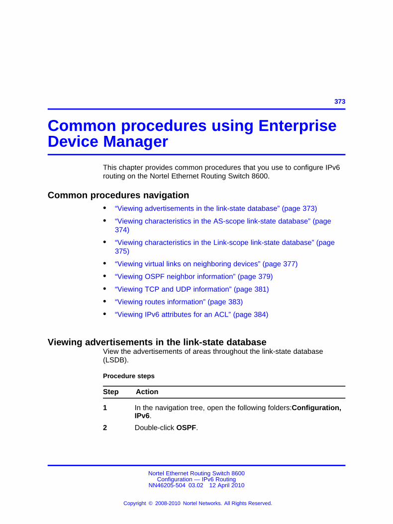
373.
Common procedures using EnterpriseDevice Manager
This chapter provides common procedures that you use to configure IPv6routing on the Nortel Ethernet Routing Switch 8600.
Common procedures navigation• “Viewing advertisements in the link-state database” (page 373)
• “Viewing characteristics in the AS-scope link-state database” (page374)
• “Viewing characteristics in the Link-scope link-state database” (page375)
• “Viewing virtual links on neighboring devices” (page 377)
• “Viewing OSPF neighbor information” (page 379)
• “Viewing TCP and UDP information” (page 381)
• “Viewing routes information” (page 383)
• “Viewing IPv6 attributes for an ACL” (page 384)
Viewing advertisements in the link-state databaseView the advertisements of areas throughout the link-state database(LSDB).
Procedure steps
Step Action
1 In the navigation tree, open the following folders:Configuration,IPv6.
2 Double-click OSPF.
Nortel Ethernet Routing Switch 8600Configuration — IPv6 Routing
NN46205-504 03.02 12 April 2010
Copyright © 2008-2010 Nortel Networks. All Rights Reserved.
.

374 Common procedures using Enterprise Device Manager
3 Click the Area-scope LSDB tab.
--End--
Variable definitionsUse the data in the following table to use the Area-scope LSDB tab.
Variable Value
AreaId A read-only field indicating the 32-bit integer that uniquelyidentifies an area. Area ID 0.0.0.0 is used for the OSPFbackbone.
Type A read-only field indicating the OSPF interface type.By default, switches can determine this value from thecorresponding value of ifType. Broadcast LANs, such asEthernet and IEEE 802.5, use the value broadcast; X.25 andsimilar technologies use the value nbma; and point-to-pointlinks use the value pointToPoint.
RouterId A read-only field indicating the 32-bit integer that uniquelyidentifies the router in the autonomous system.
Lsid A read-only field indicating that the link-state ID is anLS type-specific field containing either a router ID or anIPv6 address. It identifies the piece of the routing domaindescribed by the advertisement.
Sequence A read-only field indicating that the sequence number is asigned 32-bit integer that identifies old and duplicate link-stateadvertisements.
Age A read-only field indicating the age in seconds of the link-stateadvertisement.
Checksum A read-only field indicating the checksum of the completecontents of the advertisement, except the age field. Theage field is not included so that the advertisement ageincrements without updating the checksum. The checksumused is the same for Industry Standards Organization (ISO)connectionless datagrams, the Fletcher checksum.
TypeKnown A read-only field indicating the LSA type recognized by thisrouter.
Viewing characteristics in the AS-scope link-state databaseView the characteristics of the autonomous system (AS)-scope link-statedatabase.
Nortel Ethernet Routing Switch 8600Configuration — IPv6 Routing
NN46205-504 03.02 12 April 2010
Copyright © 2008-2010 Nortel Networks. All Rights Reserved.
.

Viewing characteristics in the Link-scope link-state database 375
Procedure steps
Step Action
1 In the navigation tree, open the following folders:Configuration,IPv6.
2 Double-click OSPF.
3 Click the AS-scope LSDB tab.
--End--
Variable definitionsUse the data in the following table to use the AS-scope LSDB tab.
Variable Value
Type A read-only field indicating the OSPF interface type.By default, switches can determine this value from thecorresponding value of ifType. Broadcast LANs, such asEthernet and IEEE 802.5, use the value broadcast; X.25 andsimilar technologies use the value nbma; and point-to-pointlinks use the value pointToPoint.
RouterId A read-only field indicating the 32-bit integer that uniquelyidentifies the router in the autonomous system.
Lsid A read-only field indicating that the link-state ID is anLS type-specific field containing either a router ID or anIPv6 address. It identifies the piece of the routing domaindescribed by the advertisement.
Sequence A read-only field indicating that the sequence number isa signed 32-bit integer that identifies old and duplicatelink-state advertisements.
Age A read-only field indicating the age in seconds of thelink-state advertisement.
Checksum A read-only field indicating the checksum of the completecontents of the advertisement, except the age field. Theage field is not affected so that the advertisement age valueincrements without updating the checksum. The checksumused is the same for ISO connectionless datagrams, theFletcher checksum.
TypeKnown A read-only field indicating the LSA type recognized by thisrouter.
Viewing characteristics in the Link-scope link-state databaseView the characteristics of the Link-scope link-state database.
Nortel Ethernet Routing Switch 8600Configuration — IPv6 Routing
NN46205-504 03.02 12 April 2010
Copyright © 2008-2010 Nortel Networks. All Rights Reserved.
.

376 Common procedures using Enterprise Device Manager
Procedure steps
Step Action
1 In the navigation tree, open the following folders:Configuration,IPv6.
2 Double-click OSPF.
3 Click the Link-scope LSDB tab.
--End--
Variable definitionsUse the data in the following table to use the Link-scope LSDB tab.
Variable Value
LocalIfIndex A read-only field indicating the identifier of the link from whichthe LSA was received.
Type A read-only field indicating the OSPF interface type.By default, switches can determine this value from thecorresponding value of ifType. Broadcast LANs, such asEthernet and IEEE 802.5, use the value broadcast; X.25 andsimilar technologies use the value nbma; and point-to-pointlinks use the value pointToPoint.
RouterId A read-only field indicating the 32-bit integer that uniquelyidentifies the router in the autonomous system.
Lsid A read-only field indicating that the link-state ID is an LStype-specific field containing either a router ID or an IPv6address. It identifies the piece of the routing domain describedby the advertisement.
Sequence A read-only field indicating that the sequence number is asigned 32-bit integer that identifies old and duplicate link-stateadvertisements.
Age A read-only field indicating the age in seconds of the link-stateadvertisement.
Checksum A read-only field indicating the checksum of the completecontents of the advertisement, except the age field. Theage field is not affected so that the advertisement age valueincrements without updating the checksum. The checksumused is the same for ISO connectionless datagrams, theFletcher checksum.
TypeKnown A read-only field indicating the LSA type recognized by thisrouter.
Nortel Ethernet Routing Switch 8600Configuration — IPv6 Routing
NN46205-504 03.02 12 April 2010
Copyright © 2008-2010 Nortel Networks. All Rights Reserved.
.

Viewing virtual links on neighboring devices 377
Viewing virtual links on neighboring devicesYou can view area and virtual link configuration for the neighboring deviceon the Virtual Neighbor tab.
Procedure steps
Step Action
1 In the navigation tree, open the following folders:Configuration,IPv6.
2 Double-click OSPF.
3 Click the Virtual Neighbors tab.
--End--
Variable definitionsUse the data in the following table to use the Virtual Neighbors tab.
Variable Value
Area A read-only field that indicates the subnetwork in whichthe virtual neighbor resides.
RtrId A read-only field that indicates the 32-bit integer(represented as a type IpAddress) uniquely identifyingthe neighboring router in the autonomous system.
LocalIfIndex A read-only field that indicates the interface indexnumber of the virtual neighboring router.
AddressType A read-only field that indicates the address type ofOSPFv3 addresses including,
• unknown
• ipv4
• ipv6
• ipv4z
• ipv6z
• dns
Address A read-only field that indicates the virtual neighboringrouter IPv6 address.
Options A read-only field that indicates the bit maskcorresponding to the neighbor options field.
Nortel Ethernet Routing Switch 8600Configuration — IPv6 Routing
NN46205-504 03.02 12 April 2010
Copyright © 2008-2010 Nortel Networks. All Rights Reserved.
.

378 Common procedures using Enterprise Device Manager
Variable Value
State A read-only field that indicates the OSPF interfacestate,
• down
• attempt
• init
• twoWay
• exchangeStart
• exchange
• loading
• full
Events A read-only field that indicates the number of statechanges or error events that occurred between theOSPF router and the neighbor router.
LsRetransQLen A read-only field that indicates the number of elapsedseconds between advertising retransmissions of thesame packet to a neighbor.
HelloSuppressed A read-only field that indicates whether Hello packetsare suppressed on the neighbor.
NbrIfId A read-only field that indicates the interface ID that theneighbor advertises in Hello packets on this link; thelocal interface index for the neighbor.
RestartHelperStatus A read-only field that indicates whether the router is ahitless restart helper for the neighbor,
• notHelping
• helping
RestartHelperAge A read-only field that indicates the remaining time inthe current OSPF hitless restart interval. The range is1 through 1800.
RestartHelperExitReason
A read-only field that indicates the outcome of thelast attempt to act as a hitless restart helper for theneighbor,
• none indicates no restart was attempted (default)
• inProgress indicates a restart attempt is currentlyunderway
• completed indicates a completed restart
Nortel Ethernet Routing Switch 8600Configuration — IPv6 Routing
NN46205-504 03.02 12 April 2010
Copyright © 2008-2010 Nortel Networks. All Rights Reserved.
.

Viewing OSPF neighbor information 379
Variable Value
• timedout indicates a timed-out restart
• topologyChanged indicates a cancelled restart dueto a topology change
Viewing OSPF neighbor informationTwo routers with interfaces to a common network are neighbors andappear on the Neighbors tab for each neighboring router. The OSPF Helloprotocol maintains and dynamically discovers neighbor relationships.The exception is an NBMA network; you manually configure permanentneighbors on each router eligible to become the DR.
Procedure steps
Step Action
1 In the navigation tree, open the following folders:Configuration,IPv6.
2 Double-click OSPF.
3 Click the Neighbors tab.
--End--
Variable definitionsUse the data in the following table to configure the Neighbors tab.
Variable Value
IfIndex A read-only field indicating the local link ID of the linkover which the neighbor is reached.
Rtrld A read-only field indicating the router ID of theneighboring router, which in OSPF uses the sameformat as an IPv6 address but identifies the routerindependent of IPv6 address.
Address A read-only field indicating the IPv6 address for theneighbor associated with the local link.
Options A read-only field indicating the bit mask correspondingto the options field on the neighbor.
Priority A read-only field indicating the preferential treatmentassignment, which places the transmitted packets intoqueues. The priority field also indicates the possibleselection of the priority field in the data link headerwhen the switch forwards the packet.
Nortel Ethernet Routing Switch 8600Configuration — IPv6 Routing
NN46205-504 03.02 12 April 2010
Copyright © 2008-2010 Nortel Networks. All Rights Reserved.
.

380 Common procedures using Enterprise Device Manager
Variable Value
State A read-only field indicating the OSPF interface state:
• down
• attempt
• init
• twoWay
• exchangeStart
• exchange
• loading
• full
Events A read-only field indicating the number of statechanges or error events occurring between the OSPFrouter and the neighbor router.
LSRetransQLen A read-only field indicating the number of elapsedseconds between advertising retransmissions of thesame packet to a neighbor.
HelloSuppressed A read-only field indicating whether hellos aresuppressed at a neighbor.
NbrIfid A read-only field indicating the interface ID that theneighbor advertises in hello packets on this link; thatis, the neighbor local interface index.
RestartHelperStatus A read-only field indicating that the router is a hitlessrestart helper for the neighbor,
• notHelping
• helping
RestartHelperAge A read-only field indicating the time remaining incurrent OSPF hitless restart interval, if the router actsas a restart helper for the neighbor. The range is 1through 1800 seconds.
RestartHelperExitReason
A read-only field indicating the outcome of the lastattempt to act as a hitless restart helper for theneighbor,
• none indicates no restart was attempted (default)
• inProgress indicates a restart attempt is currentlyunderway
• completed indicates a completed restart
Nortel Ethernet Routing Switch 8600Configuration — IPv6 Routing
NN46205-504 03.02 12 April 2010
Copyright © 2008-2010 Nortel Networks. All Rights Reserved.
.

Viewing TCP and UDP information 381
Variable Value
• timedout indicates a timed-out restart
• topologyChanged indicates a cancelled restart dueto the topology change
Viewing TCP and UDP informationView TCP and UDP information to view the current configuration.
Procedure steps
Step Action
1 In the navigation tree, open the following folders:Configuration,IPv6.
2 Double-click TCP/UDP.
3 Select the required tab:
• TCP Globals
• TCP Connections
• TCP Listeners
• UDP Endpoints
--End--
Variable definitionsUse the data in the following table to use the TCP/UDP tabs.
Variable Value
TCP Globals tab
RtoAlgorithm Determines the timeout value used forretransmitting unacknowledged octets.
RtoMin Displays the minimum time (inmilliseconds) permitted by a TCPimplementation for the retransmissiontimeout.
RtoMax Displays the maximum time (inmilliseconds) permitted by a TCPimplementation for the retransmissiontimeout.
MaxConn Displays the maximum connections forthe device.
Nortel Ethernet Routing Switch 8600Configuration — IPv6 Routing
NN46205-504 03.02 12 April 2010
Copyright © 2008-2010 Nortel Networks. All Rights Reserved.
.

382 Common procedures using Enterprise Device Manager
Variable Value
TCP Connections tab
LocalAddressType Displays the type (IPv6 or IPv4) for theaddress in the LocalAddress field.
LocalAddress Displays the IPv6 address for the TCPconnection.
LocalPort Displays the local port number for theTCP connection.
RemAddressType Displays the type (IPv6, IPv4) forthe remote address for the TCPconnection.
RemAddress Displays the IPv6 address for theremote TCP connection.
RemPort Displays the remote port number forthe TCP connection.
State Displays an integer that represents thestate for the connection:
• 1: closed
• 2: listen
• 3: synSent
• 4: synReceived
• 5: established
• 6: finWait1
• 7: finWait2
• 8: closeWait
• 9: lastAck(9)
• 10: closing
• 11: timeWait
• 12: deleteTCB
Process Displays the process ID for the systemprocess associated with the TCPconnection.
TCP Listeners tab
LocalAddressType Displays the type for the address (IPv6or IPv4).
LocalAddress Displays the local IPv6 address.
LocalPort Displays the local port number.
Nortel Ethernet Routing Switch 8600Configuration — IPv6 Routing
NN46205-504 03.02 12 April 2010
Copyright © 2008-2010 Nortel Networks. All Rights Reserved.
.

Viewing routes information 383
Variable Value
Process Displays the ID for the TCP process.
UDP Endpoints tab
LocalAddressType Displays the local address type (IPv6or IPv4).
LocalAddress Displays the local IPv6 address.
LocalPort Displays the local port number.
RemoteAddressType Displays the remote address type(IPv6 or IPv4).
RemoteAddress Displays the remote IPv6 address.
RemotePort Displays the remote port number.
Instance Distinguishes between multipleprocesses connected to the UDPendpoint.
Process Displays the ID for the UDP process.
Viewing routes informationView routes information to view the current configuration.
Procedure steps
Step Action
1 In the navigation tree, open the following folders:Configuration,IPv6.
2 Double-click IPv6.
3 Click the Routes tab.
--End--
Variable definitionsUse the data in the following table to use the Routes tab.
Variable Value
Dest Displays the IPv6 destination network address. Theprefix value must match the PrefixLength.
PfxLength Displays the number bits you want to advertise fromthe prefix. The prefix value must match the value in theDest field. The range is 0 to 128.
IfIndex Displays the ID for the VLAN or port.
NextHop Displays the IPv6 address of the next hop of this route.
Nortel Ethernet Routing Switch 8600Configuration — IPv6 Routing
NN46205-504 03.02 12 April 2010
Copyright © 2008-2010 Nortel Networks. All Rights Reserved.
.

384 Common procedures using Enterprise Device Manager
Variable Value
Protocol Displays the routing protocol (OSPF).
Metric Displays the metric assigned to this interface. Thedefault value of the metric is the reference bandwidthor ifSpeed. The value of the reference bandwidth isconfigured by the rcOspfv3ReferenceBandwidth object.
Viewing IPv6 attributes for an ACLView IPv6 attributes for an ACL to view ACE Advanced entries associatedwith an ACL.
Procedure steps
Step Action
1 In the navigation tree, open the following folders:Configuration,Security, Data Path.
2 Double-click Advanced Filters (ACE/ACLs).
3 Click the ACL tab.
4 Select any of the parameters of an IPv6 ACL.
5 Click IPv6.
--End--
Variable definitionsUse the data in the following table to use the ACE IPv6, ACL (x) dialogbox.
Variable Value
ACL ID Specifies the unique identifier for the ACL.
ACEID Specifies the unique identifier for the ACE.
SrcAddrList Lists the source IPv6 addresses.
SrcAddrOper Specifies equal (eq) or not equal (ne) or any in relationto the listed source addresses.
DstAddrList Lists the IPv6 destination addresses.
DstAddrOper Specifies equal (eq) or not equal (ne) or any in relationto the listed destination addresses.
NxtHdrNxtHdr Displays the next header value.
NxtHdrOper Specifies equal (eq) or not equal (ne) or any in relationto the listed next header.
Nortel Ethernet Routing Switch 8600Configuration — IPv6 Routing
NN46205-504 03.02 12 April 2010
Copyright © 2008-2010 Nortel Networks. All Rights Reserved.
.

385.
Common procedures using the CLIThis chapter describes common procedures that you use while configuringIPv6 routing on the Nortel Ethernet Routing Switch 8600.
Common procedures navigation• “Pinging a device” (page 385)
Pinging a deviceWhen you ping a device, the switch sends an Internet Control MessageProtocol (ICMP) packet to the target device. If the device receives thepacket, it sends a ping reply. When the switch receives the reply, amessage indicates that the specified IP address is responding. If no replyis received, a message indicates that the address is not responding.
Procedure steps
Step Action
1 Ping a device by using the following command:
ping <HostName/ipv4address/ipv6address> [scopeid<value>] [datasize <value> ] [count <value> ] [-s][-I <value> ] [-t <value> ] [-d]
--End--
Variable definitionsUse the data in the following table to use the ping command.
Nortel Ethernet Routing Switch 8600Configuration — IPv6 Routing
NN46205-504 03.02 12 April 2010
Copyright © 2008-2010 Nortel Networks. All Rights Reserved.
.

386 Common procedures using the CLI
Variable Value
count <value> Configures the number of times toping. For IPv4 or IPv6, the range is1–9999.
ATTENTIONTo specify a count for the pingoperation, you must also specifya size. For example: ping8888:0:0:0:0:0:0:1 count10
-d Configures ping debugging (forIPv4/IPv6).
datasize <value> Configures the size of ping data sentin bytes, for IPv4: 16–4076, for IPv6:16-65487.
HostName/ipv6address Specifies the host name or IPv6(x:x:x:x:x:x:x:x) address {string length1–256}.
-I <value> Configures the interval betweentransmissions in seconds (1–60).
-s Configures the continuous ping atthe interval rate defined by the [-I]parameter (for IPv4/IPv6)
scopeid <value> Configures the circuit ID (for IPv6)(1–9999).
-t <value> Configures the no answer timeoutvalue (IPv4 or IPv6) {1–120}.
Nortel Ethernet Routing Switch 8600Configuration — IPv6 Routing
NN46205-504 03.02 12 April 2010
Copyright © 2008-2010 Nortel Networks. All Rights Reserved.
.

387.
Common procedures using the NNCLIThis chapter describes common procedures that you use while configuringIPv6 routing on the Nortel Ethernet Routing Switch 8600.
Common procedures navigation• “Pinging a device” (page 387)
Pinging a deviceWhen you ping a device, the switch sends an Internet Control MessageProtocol (ICMP) packet to the target device. If the device receives thepacket, it sends a ping reply. When the switch receives the reply, amessage indicates that the specified IP address is responding. If no replyis received, a message indicates that the address is not responding.
Procedure steps
Step Action
1 Ping a device by using the following command:
ping <HostName/ipv4address/ipv6address> [scopeid<value>] [datasize <value> ] [count <value> ] [-s][-I <value> ] [-t <value> ] [-d]
--End--
Variable definitionsUse the data in the following table to use the ping command.
Nortel Ethernet Routing Switch 8600Configuration — IPv6 Routing
NN46205-504 03.02 12 April 2010
Copyright © 2008-2010 Nortel Networks. All Rights Reserved.
.
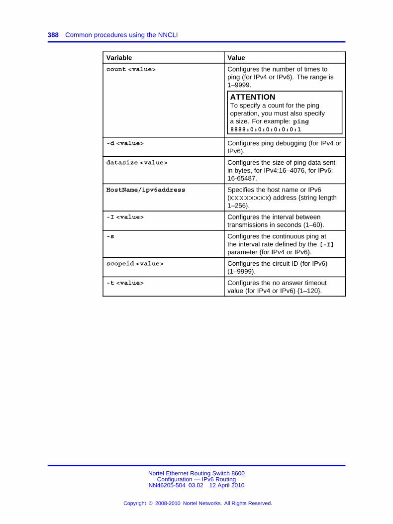
388 Common procedures using the NNCLI
Variable Value
count <value> Configures the number of times toping (for IPv4 or IPv6). The range is1–9999.
ATTENTIONTo specify a count for the pingoperation, you must also specifya size. For example: ping8888:0:0:0:0:0:0:1
-d <value> Configures ping debugging (for IPv4 orIPv6).
datasize <value> Configures the size of ping data sentin bytes, for IPv4:16–4076, for IPv6:16-65487.
HostName/ipv6address Specifies the host name or IPv6(x:x:x:x:x:x:x:x) address {string length1–256}.
-I <value> Configures the interval betweentransmissions in seconds (1–60).
-s Configures the continuous ping atthe interval rate defined by the [-I]parameter (for IPv4 or IPv6).
scopeid <value> Configures the circuit ID (for IPv6)(1–9999).
-t <value> Configures the no answer timeoutvalue (for IPv4 or IPv6) {1–120}.
Nortel Ethernet Routing Switch 8600Configuration — IPv6 Routing
NN46205-504 03.02 12 April 2010
Copyright © 2008-2010 Nortel Networks. All Rights Reserved.
.

389.
IPv6 CLI configurationThis chapter contains enhanced configuration examples of IPv6 routingwith the Nortel Ethernet Routing Switch 8600.
IPv6 CLI configuration navigation• “OSPF configuration” (page 389)
• “Routing both IPv4 and IPv6 traffic” (page 392)
• “Tunnel configuration between brouter ports” (page 394)
• “Tunnel configuration between VLANs” (page 398)
OSPF configurationYou can configure OSPFv3 on an interface (brouter port) or VLAN. Thisconfiguration example configures the following in reference to EthernetRouting Switch 8600-B:
• Configure an IPv6 VLAN, VLAN 2, with port member 3/1.
• Configure a core IPv6 brouter port, port 7/1.
• Use IPv6 address 2001:100:102::/64.
Figure 20 "Configuration example network" (page 389) represents thenetwork for the configuration example.
Figure 20Configuration example network
Nortel Ethernet Routing Switch 8600Configuration — IPv6 Routing
NN46205-504 03.02 12 April 2010
Copyright © 2008-2010 Nortel Networks. All Rights Reserved.
.

390 IPv6 CLI configuration
Configuring OSPFv3Procedure steps
Step Action
1 Configure VLAN 2 and add port members.
For IPv6, configure port-based or protocol-based VLANs. Forthis example, create port-based VLAN 2:
ERS8600-B:5# config vlan 2 create byport 1ERS8600-B:5# config vlan 2 ports add 3/1
2 Configure and enable the IPv6 address on VLAN 2:
ERS8600-B:5# config vlan 2 ipv6 create addr2001:100:102:202::1/64ERS8600-B:5# config vlan 2 ipv6 admin enable
3 Enable OSPFv3 on VLAN 2:
ERS8600-B:5# config vlan 2 ipv6 ospf create 0.0.0.0ERS8600-B:5# config vlan 2 ipv6 ospf admin-statusenable
4 Configure brouter port 7/1 with IPv6:
ERS8600-B:5# config ethernet 7/1 ipv6 create addr2001:100:102:201::1/64 vlan 3999ERS8600-B:5# config ethernet 7/1 ipv6 admin enable
5 Enable OSPFv3 on brouter port 7/1:
ERS8600-B:5# config Ethernet 7/1 ipv6 ospf create0.0.0.0ERS8600-B:5# config ethernet 7/1 ipv6 ospfadmin-status enable
--End--
By default, IPv6 router discovery is enabled. Any IPv6 device connectedto VLAN 2 discovers the 2001:100:102:202::1 address belonging toERS8600-B. Verify the discovery by using the following command:
ERS8600-B:5# config vlan 2 ipv6 nd info
Verifying operations from ERS 8600-AThe following commands verify that ERS 8600-A is learning routes fromERS 8600-B.
Nortel Ethernet Routing Switch 8600Configuration — IPv6 Routing
NN46205-504 03.02 12 April 2010
Copyright © 2008-2010 Nortel Networks. All Rights Reserved.
.

OSPF configuration 391
Procedure steps
Step Action
1 Enter the following command to verify that ERS 8600-A learnedroutes to VLAN 2 from ERS 8600-B:
ERS8600-A:6# show ipv6 route info
2 Verify connectivity to both IPv6 interfaces with the pingcommand:
ERS8600-A:6# ping 2001:100:102:201::12001:0100:0102:0201:0000:0000:0000:0001 isAliveERS8600-A:6# ping 2001:100:102:202::12001:0100:0102:0202:0000:0000:0000:0001 isAlive
3 Verify the OSPFv3 neighbor by using the following command:
ERS8600-A:6# show ipv6 ospf neighbor
4 From ERS 8600-A, verify the OSPF router ID and link stateinformation through ERS 8600-B by using the followingcommand:
ERS8600-A:6# show ipv6 ospf lsdb detail
5 Verify the IPv6 neighbor cache by using the following command:
ERS8600-A:6# show ipv6 neighbor info
--End--
Verifying operations from ERS 8600-BVerify the OSPFv3 configuration and operations from ERS 8600-B.
Procedure steps
Step Action
1 Verify OSPF by using the following command:
ERS8600-B:5# show ipv6 ospf info
2 Verify IPv6 addresses:
ERS8600-B:5# show ipv6 addr info
3 Verify neighbor discovery by using the following command. In asuccessful configuration, the IPv6 VLAN 2 and brouter port 7/1prefixes appear in the output.
Nortel Ethernet Routing Switch 8600Configuration — IPv6 Routing
NN46205-504 03.02 12 April 2010
Copyright © 2008-2010 Nortel Networks. All Rights Reserved.
.

392 IPv6 CLI configuration
ERS8600-B:5# show ipv6 nd_prefix info
--End--
Verifying OSPFv3 operations from a PCIn the following example, a Windows XP desktop PC connects to VLAN 2on ERS 8600-B.
Procedure steps
Step Action
1 At the command prompt (select Start, Run, enter cmd, andclick OK), enter the following commands to verify that the IPv6addresses from ERS 8600-B appears in the output:
C:\>netshnetsh>interfacenetsh interface>ipv6netsh interface ipv6>show neighbors
2 Verify that you can ping the IPv6 network address for ERS8600-B:
C:\> ping 2001:100:102:202::1
3 Verify that you can ping the IPv6 network address for ERS8600-A:
C:\> ping 2001:100:102:201::2
--End--
Routing both IPv4 and IPv6 trafficThe following figure shows the configuration of a dual-stack system ora switch that routes both IPv4 and IPv6 traffic. The following examplecontains steps to configure both brouter ports and VLANs.
Nortel Ethernet Routing Switch 8600Configuration — IPv6 Routing
NN46205-504 03.02 12 April 2010
Copyright © 2008-2010 Nortel Networks. All Rights Reserved.
.

Routing both IPv4 and IPv6 traffic 393
Figure 21Dual stack system
Use the following example to configure OSPF.
Procedure steps
Step Action
1 Create an IPv4 interface.
Enter the following command for a VLAN:
config vlan 100 ip create 1.1.1.1/24 100
Enter the following command for a brouter port:
config ethernet 2/1 ip create 1.1.1.1/24 100
2 Configure an OSPF area for the interface.
Enter the following command for a VLAN:
config vlan 100 ip ospf area 1.1.1.1
Enter the following command for a brouter port:
config ethernet 2/1 ip ospf area 1.1.1.1
3 Enable OSPF on the interface.
Enter the following command for a VLAN:
Nortel Ethernet Routing Switch 8600Configuration — IPv6 Routing
NN46205-504 03.02 12 April 2010
Copyright © 2008-2010 Nortel Networks. All Rights Reserved.
.

394 IPv6 CLI configuration
config vlan 100 ip ospf enable
Enter the following command for a brouter port:
config ethernet 2/1 ip ospf enable
4 Create an IPv6 interface on the same VLAN or brouter portwhere you configured IPv4.
Enter the following command for a VLAN:
config vlan 100 ipv6 create addr 3001::1/64
Enter the following command for a brouter port:
config ethernet 2/1 ipv6 create addr 3001::1/64 vlan 100
5 Enable the IPv6 interface.
Enter the following command for a VLAN:
config vlan 100 ipv6 admin-status en
Enter the following command for a brouter port:
config ethernet 2/1 ipv6 admin-status en
6 Create an OSPFv3 area by using the following command:
config ipv6 ospf area 2.2.2.2 create
7 Create an OSPFv3 interface.
Enter the following command for a VLAN:
config vlan 100 ipv6 ospf create 2.2.2.2 metric 2
Enter the following command for a brouter port:
config ethernet 2/1 ipv6 ospf create 2.2.2.2 metric 2
8 Enable OSPF on the IPv6 interface.
Enter the following command for a VLAN:
config vlan 100 ipv6 ospf admin enable
Enter the following command for a brouter port:
config ethernet 2/1 ipv6 ospf admin enable
--End--
Tunnel configuration between brouter portsThe following figure shows the tunnel configuration between brouter ports.
Nortel Ethernet Routing Switch 8600Configuration — IPv6 Routing
NN46205-504 03.02 12 April 2010
Copyright © 2008-2010 Nortel Networks. All Rights Reserved.
.

Tunnel configuration between brouter ports 395
Figure 22Tunnel configuration between brouter ports
Prerequisites
• You must configure static routes, RIP, or OSPF on both the source(8600 1) and remote (8600 2) IPv4 interfaces to communicate on anIPv4 network.
• The brouter ports on the source and destination devices use IPv4addresses available through the IPv4 network.
This example section requires you to perform the following procedures:
1. “Creating an IPv6 VLAN with ports on the source device” (page 395)
2. “Creating an IPv4 brouter port on the source device” (page 396)
3. “Creating an IPv6 VLAN with ports on the remote device” (page 396)
4. “Creating an IPv4 brouter port on the destination device” (page 397)
5. “Configuring a tunnel on the source device” (page 397)
6. “Configuring a tunnel on the destination device” (page 397)
Creating an IPv6 VLAN with ports on the source deviceConfigure the IPv6 VLAN with ports (VLAN 10 in the figure) on the sourcedevice, or 8600.
Procedure steps
Step Action
1 Create a VLAN by using the following command:
Nortel Ethernet Routing Switch 8600Configuration — IPv6 Routing
NN46205-504 03.02 12 April 2010
Copyright © 2008-2010 Nortel Networks. All Rights Reserved.
.

396 IPv6 CLI configuration
config vlan 10 create byport 1
2 Add ports to the VLAN by using the following command:
config vlan 10 ports add 3/1
3 Assign an IPv6 address to the to the VLAN by using the followingcommand:
config vlan 10 ipv6 create addr 4000::1/120
4 Enable the new VLAN by using the following command:
config vlan 10 ipv6 admin enable
--End--
Creating an IPv4 brouter port on the source deviceProcedure steps
Step Action
1 Create a brouter port with an IPv4 address by using the followingcommand:
config ethernet 3/30 ip create 172.21.80.1/24 1000
2 Enable OSPF on the port by using the following command:
config ethernet 3/30 ip ospf enable
3 Enable OSPF on the device by using the following command:
config ip ospf enable
--End--
Creating an IPv6 VLAN with ports on the remote deviceConfigure the IPv6 VLAN with ports (VLAN 40 in the figure) on thedestination device, or 8600.
Procedure steps
Step Action
1 Create a VLAN by using the following command:
config vlan 40 create byport 1
2 Add ports to the VLAN by using the following command:
config vlan 40 ports add 3/2
3 Assign an IPv6 address to the to the VLAN by using the followingcommand:
Nortel Ethernet Routing Switch 8600Configuration — IPv6 Routing
NN46205-504 03.02 12 April 2010
Copyright © 2008-2010 Nortel Networks. All Rights Reserved.
.

Tunnel configuration between brouter ports 397
config vlan 40 ipv6 create addr 4000::2/120
4 Enable the new VLAN by using the following command:
config vlan 40 ipv6 admin enable
--End--
Creating an IPv4 brouter port on the destination deviceCreate an IPv4 brouter port on the destination device.
Procedure steps
Step Action
1 Create a brouter port with an IPv4 address by using the followingcommand:
config ethernet 3/30 ip create 192.168.20.1/24 2000
2 Enable OSPF on the port by using the following command:
config ethernet 3/30 ip ospf enable
3 Enable OSPF on the device by using the following command:
config ip ospf enable
--End--
Configuring a tunnel on the source deviceConfigure a tunnel on the source device.
Procedure steps
Step Action
1 Enter the following command to configure a tunnel on the sourcedevice. Enter the IPv4 address for the destination port for theremote-address value.
config ipv6 tunnel 1 create local-addr 172.21.80.1ipv6addr 2500::1/120 remote-address 192.168.20.1
--End--
Configuring a tunnel on the destination deviceConfigure a tunnel on the destination device.
Nortel Ethernet Routing Switch 8600Configuration — IPv6 Routing
NN46205-504 03.02 12 April 2010
Copyright © 2008-2010 Nortel Networks. All Rights Reserved.
.

398 IPv6 CLI configuration
Procedure steps
Step Action
1 Enter the following command to configure a tunnel on thedestination device. Enter the IPv4 address for the source portfor the remote-address value.
config ipv6 tunnel 1 create local-addr 192.168.20.1ipv6addr 2500::2/120 remote-address 172.21.80.1
--End--
Tunnel configuration between VLANsThe following figure shows the configuration of a tunnel between VLANs.
Figure 23Tunnel configuration between VLANs
Prerequisites
• You must configure static routes, RIP, or OSPF on both the source(8600 1) and remote (8600 2) IPv4 interfaces to communicate on anIPv4 network.
• Configure IPv4 address on the VLANs. Test the source and destinationaddresses by using the ping command.
This example requires you to perform the following procedures:
1. “Configuring an IPv6 VLAN on the source device” (page 399)
2. “Configuring an IPv4 VLAN on the source device” (page 399)
3. “Configuring an IPv6 VLAN on the destination device” (page 400)
Nortel Ethernet Routing Switch 8600Configuration — IPv6 Routing
NN46205-504 03.02 12 April 2010
Copyright © 2008-2010 Nortel Networks. All Rights Reserved.
.

Tunnel configuration between VLANs 399
4. “Configuring an IPv4 VLAN on the destination device” (page 400)
5. “Configuring the tunnel on the source device” (page 401)
6. “Configuring the tunnel on the destination device” (page 401)
Configuring an IPv6 VLAN on the source deviceConfigure the IPv6 VLAN (VLAN 10 in the figure) on the source device, or8600 1 in the figure.
Procedure steps
Step Action
1 Create a VLAN by using the following command:
config vlan 10 create byport 1
2 Add ports to the VLAN by using the following command:
config vlan 10 ports add 3/1
3 Assign an IPv6 address to the to the VLAN by using the followingcommand:
config vlan 10 ipv6 create addr 4000::1/120
4 Enable the new VLAN by using the following command:
config vlan 10 ipv6 admin enable
--End--
Configuring an IPv4 VLAN on the source deviceConfigure an IPv4 VLAN (VLAN 20 in the figure) on the source device(8600 1 in the figure). The IPv4 VLAN encapsulates the IPv6 VLAN acrossthe IPv4 network.
Procedure steps
Step Action
1 Create the VLAN by using the following command:
config vlan 20 create byport 1
2 Add ports to the VLAN by using the following command:
config vlan 20 ports add 3/30
3 Assign an IPv4 address to the VLAN by using the followingcommand:
config vlan 20 ip create 172.21.80.1/24
Nortel Ethernet Routing Switch 8600Configuration — IPv6 Routing
NN46205-504 03.02 12 April 2010
Copyright © 2008-2010 Nortel Networks. All Rights Reserved.
.

400 IPv6 CLI configuration
4 Enable OSPF on the VLAN by using the following command:
config vlan 20 ip ospf enable
5 Enable OSPF on the device by using the following command:
config ip ospf enable
--End--
Configuring an IPv6 VLAN on the destination deviceConfigure the IPv6 VLAN (VLAN 40 in the figure) on the destinationdevice, or 8600 2 in the figure.
Procedure steps
Step Action
1 Create a VLAN by using the following command:
config vlan 40 create byport 1
2 Add ports to the VLAN by using the following command:
config vlan 40 ports add 3/2
3 Assign an IPv6 address to the to the VLAN by using the followingcommand:
config vlan 40 ipv6 create addr 4000::2/120
4 Enable the new VLAN by using the following command:
config vlan 40 ipv6 admin enable
--End--
Configuring an IPv4 VLAN on the destination deviceConfigure an IPv4 VLAN (VLAN 30 in the figure) on the destination device(8600 2 in the figure). The IPv4 VLAN encapsulates the IPv6 VLAN acrossthe IPv4 network.
Procedure steps
Step Action
1 Create the VLAN by using the following command:
config vlan 30 create byport 1
2 Add ports to the VLAN by using the following command:
config vlan 30 ports add 3/30
Nortel Ethernet Routing Switch 8600Configuration — IPv6 Routing
NN46205-504 03.02 12 April 2010
Copyright © 2008-2010 Nortel Networks. All Rights Reserved.
.
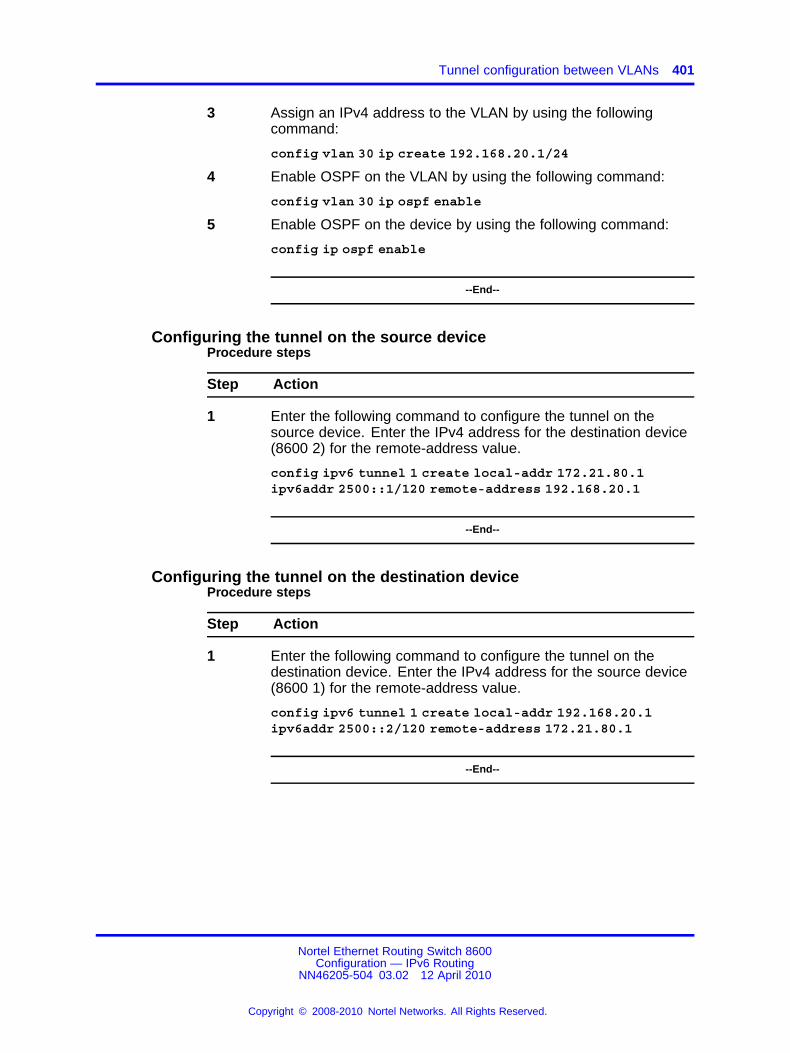
Tunnel configuration between VLANs 401
3 Assign an IPv4 address to the VLAN by using the followingcommand:
config vlan 30 ip create 192.168.20.1/24
4 Enable OSPF on the VLAN by using the following command:
config vlan 30 ip ospf enable
5 Enable OSPF on the device by using the following command:
config ip ospf enable
--End--
Configuring the tunnel on the source deviceProcedure steps
Step Action
1 Enter the following command to configure the tunnel on thesource device. Enter the IPv4 address for the destination device(8600 2) for the remote-address value.
config ipv6 tunnel 1 create local-addr 172.21.80.1ipv6addr 2500::1/120 remote-address 192.168.20.1
--End--
Configuring the tunnel on the destination deviceProcedure steps
Step Action
1 Enter the following command to configure the tunnel on thedestination device. Enter the IPv4 address for the source device(8600 1) for the remote-address value.
config ipv6 tunnel 1 create local-addr 192.168.20.1ipv6addr 2500::2/120 remote-address 172.21.80.1
--End--
Nortel Ethernet Routing Switch 8600Configuration — IPv6 Routing
NN46205-504 03.02 12 April 2010
Copyright © 2008-2010 Nortel Networks. All Rights Reserved.
.

402 IPv6 CLI configuration
Nortel Ethernet Routing Switch 8600Configuration — IPv6 Routing
NN46205-504 03.02 12 April 2010
Copyright © 2008-2010 Nortel Networks. All Rights Reserved.
.

403.
CLI show commandsThis chapter describes show commands to view the operational status ofIPv6 routing on the Nortel Ethernet Routing Switch 8600.
CLI show command navigation• “ACL or ACE information” (page 404)
• “ACT data” (page 405)
• “ACT pattern data” (page 406)
• “Basic OSPF information about a port” (page 406)
• “Extended OSPF information” (page 407)
• “Interface (VLAN or brouter port) configuration output” (page 408)
• “IPv6 static route information” (page 409)
• “MLD cache” (page 409)
• “MLD configuration for a brouter port” (page 410)
• “MLD configuration for a VLAN” (page 410)
• “Neighbor cache” (page 411)
• “Neighbor discovery prefixes” (page 411)
• “OSPF areas” (page 412)
• “OSPF configuration settings for a port” (page 412)
• “OSPF information” (page 413)
• “OSPF interface information” (page 414)
• “OSPF interface timer settings” (page 415)
• “OSPF link-state database table” (page 415)
• “OSPF neighbors” (page 417)
• “OSPF parameters configured for VLANs” (page 418)
• “OSPFv3 information for brouter ports” (page 419)
Nortel Ethernet Routing Switch 8600Configuration — IPv6 Routing
NN46205-504 03.02 12 April 2010
Copyright © 2008-2010 Nortel Networks. All Rights Reserved.
.

404 CLI show commands
• “OSPFv3 information for VLANs” (page 419)
• “Tunnel information” (page 420)
• “Tunnel interface information” (page 421)
ACL or ACE informationUse the show filter acl ace command to display information aboutACLs or ACEs. The syntax for this command is as follows.
show filter acl ace [ <acl-id> ] [ <ace-id> ]
The following table explains parameters for this command.
Table 31Command parameters
Parameter Description
ace-id Specifies a unique identifier (in therange 1–1000) for this ACE entry.
acl-id Specifies a unique identifier (in therange 1–4096) for this ACL entry.
If you enter the <acl-id>, ACE information appears for all ACEsassociated with the ACL. If you enter the <ace-id>, ACE information forthe requested ACE appears. If you provide no <acl-id>, the commandshows switch-wide ACL configuration data as viewed in the followingfigure.
Nortel Ethernet Routing Switch 8600Configuration — IPv6 Routing
NN46205-504 03.02 12 April 2010
Copyright © 2008-2010 Nortel Networks. All Rights Reserved.
.

ACT data 405
Figure 24show filter acl ace partial command output
ACT dataUse the show filter act command to display ACT data. The syntax forthis command is as follows.
show filter act [ <act-id> ]
The following table explains parameters for this command.
Table 32Command parameters
Parameter Description
act-id Specifies a unique identifier (in therange 1–4096) for this ACT entry.
If you provide no <act-id>, the command shows switch-wide ACTconfiguration data.
Nortel Ethernet Routing Switch 8600Configuration — IPv6 Routing
NN46205-504 03.02 12 April 2010
Copyright © 2008-2010 Nortel Networks. All Rights Reserved.
.

406 CLI show commands
ATTENTIONAny show command that displays information that cannot fit on oe screenappears as two tables: Part 1 and Part 2.
ACT pattern dataUse the show filter act-pattern command to display ACT patterndata. The syntax for this command is as follows.
show filter act-pattern [ <act-id> ]
The following table explains parameters for this command.
Table 33Command parameters
Parameter Description
act-id Specifies a unique identifier (in therange 1–4096) for this ACT entry.
The following figure shows sample output for this command.
Figure 25show filter act-pattern command output
Basic OSPF information about a portUse the show ports stats ospf main port command to display basicOSPF information about the specified port or for all ports. The syntax forthis command is as follows.
show ports stats ospf main port <value>
The following table explains parameters for this command.
Table 34Command parameters
Parameter Description
port <value> Specifies the port or range of portsconfigured in the format slot/port.
Nortel Ethernet Routing Switch 8600Configuration — IPv6 Routing
NN46205-504 03.02 12 April 2010
Copyright © 2008-2010 Nortel Networks. All Rights Reserved.
.

Extended OSPF information 407
Figure 26 "show ports stats ospf main command output" (page 407) showssample output for this command.
Figure 26show ports stats ospf main command output
Extended OSPF informationUse the show ports stats interface extended command to displayextended OSPF information about the specified port or for all ports. Thesyntax for this command is as follows.
show ports stats interface extended [port <value> ]
The following table explains the parameters for this command.
Table 35Command parameters
Parameter Description
port <value> Specifies the port or range of ports toconfigure in the format slot/port.
Figure 27 "show ports stats interface extended command output" (page408) shows sample output for this command.
Nortel Ethernet Routing Switch 8600Configuration — IPv6 Routing
NN46205-504 03.02 12 April 2010
Copyright © 2008-2010 Nortel Networks. All Rights Reserved.
.

408 CLI show commands
Figure 27show ports stats interface extended command output
Interface (VLAN or brouter port) configuration outputUse the show ipv6 interface info command to view the output of allconfigured interfaces. The syntax for this command is as follows.
show ipv6 interface info
View the output of a specific configured interface by using the followingcommand:
show ipv6 interface info <interface ID>
The following figure shows sample output for this command.
Nortel Ethernet Routing Switch 8600Configuration — IPv6 Routing
NN46205-504 03.02 12 April 2010
Copyright © 2008-2010 Nortel Networks. All Rights Reserved.
.

MLD cache 409
Figure 28show ipv6 interface info command output
IPv6 static route informationUse the show ipv6 static-route info command to display theexisting IPv6 static routes for the switch or for a specific net or subnet. Thesyntax for this command is as follows.
show ipv6 static-route info
Figure 29 "show ipv6 static-route info command output" (page 409) showssample output for this command.
Figure 29show ipv6 static-route info command output
MLD cacheUse the show ipv6 mld mld-cache command to display the MLD cachefor a brouter port, VLAN, or group address. The syntax for this commandis as follows.
Nortel Ethernet Routing Switch 8600Configuration — IPv6 Routing
NN46205-504 03.02 12 April 2010
Copyright © 2008-2010 Nortel Networks. All Rights Reserved.
.

410 CLI show commands
Enter the following command to view the MLD cache for a brouter port:
show ipv6 mld mld-cache port <slot/port> detail
Enter the following command to view the MLD cache for a VLAN:
show ipv6 mld mld-cache vlan <vlan id> detail
Enter the following command to view the MLD cache for a group address:
show ipv6 mld mld-cache grp-address <address> detail
MLD configuration for a brouter portUse the show ports info mld command to display configuration detailsfor MLD on a brouter port. The syntax for this command is as follows.
show ports info mld
The following figure shows sample output for this command.
Figure 30show ports info mld command output
MLD configuration for a VLANUse the show vlan info mld command to display configuration detailsfor MLD on a VLAN. The syntax for this command is as follows.
show vlan info mld
Figure 31 "Output for the show vlan info mld command" (page 411) showssample output for this command.
Nortel Ethernet Routing Switch 8600Configuration — IPv6 Routing
NN46205-504 03.02 12 April 2010
Copyright © 2008-2010 Nortel Networks. All Rights Reserved.
.

Neighbor discovery prefixes 411
Figure 31Output for the show vlan info mld command
Neighbor cacheUse the show ipv6 neighbor info command to view entries in theneighbor cache. The syntax for this command is as follows.
show ipv6 neighbor info
Figure 32 "show ipv6 neighbors info" (page 411) shows sample output forthe show ipv6 neighbors info command.
Figure 32show ipv6 neighbors info
Neighbor discovery prefixesUse the show ipv6 nd-prefix info command to view all configuredneighbor discovery prefixes. The syntax for this command is as follows.
show ipv6 nd-prefix info
The following figure shows sample output for the show ipv6 nd-prefixinfo command.
Nortel Ethernet Routing Switch 8600Configuration — IPv6 Routing
NN46205-504 03.02 12 April 2010
Copyright © 2008-2010 Nortel Networks. All Rights Reserved.
.

412 CLI show commands
Figure 33show ipv6 nd-prefix info command output
OSPF areasUse the show ipv6 ospf area command to display information aboutOSPF area parameters. The syntax for this command is as follows.
show ipv6 ospf area
Figure 34 "show ipv6 ospf area command output" (page 412) showssample output for this command.
Figure 34show ipv6 ospf area command output
OSPF configuration settings for a portUse the show ports info ospf command to display information aboutthe OSPF parameters of the specified port or all ports. The syntax for thiscommand is as follows.
show ports info ospf [ <ports> ]
The following table explains the parameters for this command.
Table 36Command parameters
Parameter Description
ports Specifies the port or range of ports toconfigure in the format slot/port.
Nortel Ethernet Routing Switch 8600Configuration — IPv6 Routing
NN46205-504 03.02 12 April 2010
Copyright © 2008-2010 Nortel Networks. All Rights Reserved.
.

OSPF information 413
Figure 35 "show ports info ospf command (partial output)" (page413) shows sample output for this command.
Figure 35show ports info ospf command (partial output)
OSPF informationUse the show ipv6 ospf info command to display the current OSPFsettings for the switch. The syntax for this command is as follows.
show ipv6 ospf info
Figure 36 "show ipv6 ospf info command output" (page 414) shows sampleoutput for this command.
Nortel Ethernet Routing Switch 8600Configuration — IPv6 Routing
NN46205-504 03.02 12 April 2010
Copyright © 2008-2010 Nortel Networks. All Rights Reserved.
.

414 CLI show commands
Figure 36show ipv6 ospf info command output
OSPF interface informationUse the show ipv6 ospf interface command to display informationabout the OSPF interface.
show ipv6 ospf interface
Figure 37 "show ipv6 ospf interface command output" (page 415) showssample output for this command.
Nortel Ethernet Routing Switch 8600Configuration — IPv6 Routing
NN46205-504 03.02 12 April 2010
Copyright © 2008-2010 Nortel Networks. All Rights Reserved.
.
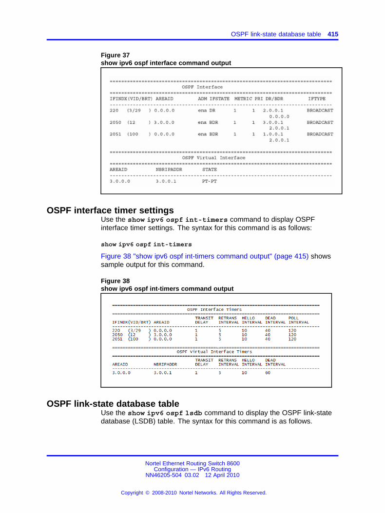
OSPF link-state database table 415
Figure 37show ipv6 ospf interface command output
OSPF interface timer settingsUse the show ipv6 ospf int-timers command to display OSPFinterface timer settings. The syntax for this command is as follows:
show ipv6 ospf int-timers
Figure 38 "show ipv6 ospf int-timers command output" (page 415) showssample output for this command.
Figure 38show ipv6 ospf int-timers command output
OSPF link-state database tableUse the show ipv6 ospf lsdb command to display the OSPF link-statedatabase (LSDB) table. The syntax for this command is as follows.
Nortel Ethernet Routing Switch 8600Configuration — IPv6 Routing
NN46205-504 03.02 12 April 2010
Copyright © 2008-2010 Nortel Networks. All Rights Reserved.
.

416 CLI show commands
show ipv6 ospf lsdb [scope <value> ] [port <value> ] [vlan<value> ] [tunnel <value> ] [area <value> ] [lsatype <value>] [lsid <value> ] [adv_rtr <value> ] [detail]
You can specify a scope, VLAN, tunnel, area string, link-stateadvertisement type (0 to 5), link state ID, or advertising router. If you addthe detail option to the command, the output contains more information.
Figure 39 "show ipv6 ospf lsdb command output" (page 416) showssample output with no variables for this command.
Figure 39show ipv6 ospf lsdb command output
Figure 40 "show ipv6 ospf lsdb detail command output" (page 417) showspartial output of this command with the detail option.
Nortel Ethernet Routing Switch 8600Configuration — IPv6 Routing
NN46205-504 03.02 12 April 2010
Copyright © 2008-2010 Nortel Networks. All Rights Reserved.
.

OSPF neighbors 417
Figure 40show ipv6 ospf lsdb detail command output
OSPF neighborsUse the show ipv6 ospf neighbor command to display OSPFneighbors configuration information. The syntax for this command is asfollows.
show ipv6 ospf neighbor
Figure 41 "show isv6 ospf neighbor command output" (page 418) showssample command output for this command.
Nortel Ethernet Routing Switch 8600Configuration — IPv6 Routing
NN46205-504 03.02 12 April 2010
Copyright © 2008-2010 Nortel Networks. All Rights Reserved.
.
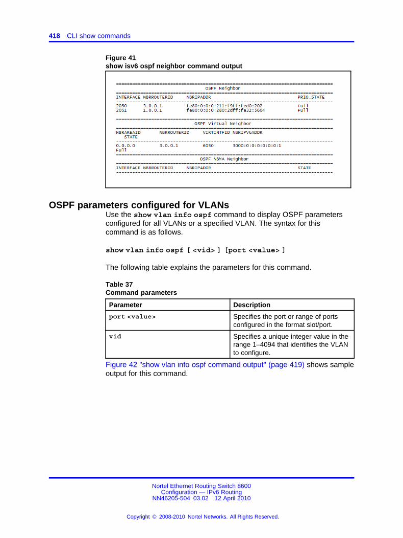
418 CLI show commands
Figure 41show isv6 ospf neighbor command output
OSPF parameters configured for VLANsUse the show vlan info ospf command to display OSPF parametersconfigured for all VLANs or a specified VLAN. The syntax for thiscommand is as follows.
show vlan info ospf [ <vid> ] [port <value> ]
The following table explains the parameters for this command.
Table 37Command parameters
Parameter Description
port <value> Specifies the port or range of portsconfigured in the format slot/port.
vid Specifies a unique integer value in therange 1–4094 that identifies the VLANto configure.
Figure 42 "show vlan info ospf command output" (page 419) shows sampleoutput for this command.
Nortel Ethernet Routing Switch 8600Configuration — IPv6 Routing
NN46205-504 03.02 12 April 2010
Copyright © 2008-2010 Nortel Networks. All Rights Reserved.
.

OSPFv3 information for VLANs 419
Figure 42show vlan info ospf command output
OSPFv3 information for brouter portsUse the show ports info ospfv3 command to view OSPFv3information for brouter ports. The syntax for this command is as follows.
show ports info ospfv3
Figure 44 "Output for show vlan info ospfv3" (page 420) shows sampleoutput for this command.
Figure 43Output for show ports info ospfv3
OSPFv3 information for VLANsUse the show vlan info ospfv3 command to view OSPFv3 informationfor VLANs. The syntax for this command is as follows.
show vlan info ospfv3
Nortel Ethernet Routing Switch 8600Configuration — IPv6 Routing
NN46205-504 03.02 12 April 2010
Copyright © 2008-2010 Nortel Networks. All Rights Reserved.
.

420 CLI show commands
Figure 44 "Output for show vlan info ospfv3" (page 420) shows sampleoutput for this command.
Figure 44Output for show vlan info ospfv3
Tunnel informationUse the show ipv6 tunnel info command to show general tunnelinformation. The syntax for this command is as follows.
show ipv6 tunnel info [ <tunnel-id> ]
The following table explains the parameters for this command.
Table 38Command parameters
Parameter Description
tunnel-id Specifies the ID number of the tunnelin the range 1-2147477248.
Figure 45 "show ipv6 tunnel info output" (page 420) shows sample outputfor the show ipv6 tunnel info command.
Figure 45show ipv6 tunnel info output
Nortel Ethernet Routing Switch 8600Configuration — IPv6 Routing
NN46205-504 03.02 12 April 2010
Copyright © 2008-2010 Nortel Networks. All Rights Reserved.
.

Tunnel interface information 421
Tunnel interface informationUse the show ipv6 tunnel interface command to show IPv6 tunnelinterface information. The syntax for this command is as follows.
show ipv6 tunnel interface [<tunnel-id>]
The following table explains the parameters for this command.
Table 39Command parameters
Parameter Description
tunnel-id Specifies the ID number of the tunnelin the range 1-2147477248 .
Figure 46 "show ipv6 tunnel interface" (page 421) shows sample output forthe show ipv6 tunnel interface command.
Figure 46show ipv6 tunnel interface
Nortel Ethernet Routing Switch 8600Configuration — IPv6 Routing
NN46205-504 03.02 12 April 2010
Copyright © 2008-2010 Nortel Networks. All Rights Reserved.
.

422 CLI show commands
Nortel Ethernet Routing Switch 8600Configuration — IPv6 Routing
NN46205-504 03.02 12 April 2010
Copyright © 2008-2010 Nortel Networks. All Rights Reserved.
.

423.
NNCLI show commandsThis chapter describes privExec mode show commands to view theoperational status of IPv6 routing on the Nortel Ethernet Routing Switch8600.
NNCLI show command navigation• “ACL or ACE information” (page 424)
• “ACT data” (page 425)
• “ACT pattern data” (page 426)
• “Basic OSPF information about a port” (page 426)
• “Extended OSPF information” (page 427)
• “Interface (VLAN or brouter port) configuration output” (page 427)
• “IPv6 static route information” (page 428)
• “MLD cache” (page 429)
• “MLD configuration ” (page 429)
• “Neighbor cache” (page 430)
• “Neighbor discovery prefixes” (page 431)
• “OSPF areas” (page 432)
• “OSPF configuration settings for a port” (page 432)
• “OSPF information” (page 433)
• “OSPF interface information” (page 434)
• “OSPF interface timer settings” (page 434)
• “OSPF link-state database table” (page 435)
• “OSPF neighbors” (page 436)
• “OSPFv3 information for VLANs” (page 436)
• “Tunnel information” (page 437)
Nortel Ethernet Routing Switch 8600Configuration — IPv6 Routing
NN46205-504 03.02 12 April 2010
Copyright © 2008-2010 Nortel Networks. All Rights Reserved.
.

424 NNCLI show commands
ACL or ACE informationUse the show filter acl ace command to display information aboutACLs or ACEs. The syntax for this command is as follows.
show filter acl ace [ <acl-id> ] [ <ace-id> ]
The following table explains parameters for this command.
Table 40Command parameters
Parameter Description
ace-id Specifies a unique identifier (in therange 1–1000) for this ACE entry.
acl-id Specifies a unique identifier (in therange 1–4096) for this ACL entry.
If you enter the <acl-id>, ACE information appears for all ACEsassociated with the ACL. If you enter the <ace-id>, ACE information forthe requested ACE appears. If you provide no <acl-id>, the commandshows switch-wide ACL configuration data as viewed in the followingfigure.
Nortel Ethernet Routing Switch 8600Configuration — IPv6 Routing
NN46205-504 03.02 12 April 2010
Copyright © 2008-2010 Nortel Networks. All Rights Reserved.
.

ACT data 425
Figure 47show filter acl ace partial command output
ACT dataUse the show filter act command to display ACT data. The syntax forthis command is as follows.
show filter act [ <act-id> ]
The following table explains parameters for this command.
Table 41Command parameters
Parameter Description
act-id Specifies a unique identifier (in therange 1 through 4096) for this ACTentry.
If you provide no<act-id>, the command shows switch-wide ACTconfiguration data.
Nortel Ethernet Routing Switch 8600Configuration — IPv6 Routing
NN46205-504 03.02 12 April 2010
Copyright © 2008-2010 Nortel Networks. All Rights Reserved.
.

426 NNCLI show commands
ATTENTIONAny show command that displays information that cannot fit on one screenappears as two tables: Part 1 and Part 2.
ACT pattern dataUse the show filter act-pattern command to display ACT patterndata. The syntax for this command is as follows.
show filter act-pattern [ <act-id> ]
The following table explains parameters for this command.
Table 42Command parameters
Parameter Description
act-id Specifies a unique identifier (in therange 1–4096) for this ACT entry.
The following figure shows sample output for this command.
Figure 48show filter act-pattern command output
Basic OSPF information about a portUse the show ports statistics ospf main command to display basicOSPF information about the specified port or for all ports. The syntax forthis command is as follows.
show ports statistics ospf main <ports>
The following table explains parameters for this command.
Table 43Command parameters
Parameter Description
<ports> Specifies the port or range of portsconfigured in the format slot/port.
Nortel Ethernet Routing Switch 8600Configuration — IPv6 Routing
NN46205-504 03.02 12 April 2010
Copyright © 2008-2010 Nortel Networks. All Rights Reserved.
.
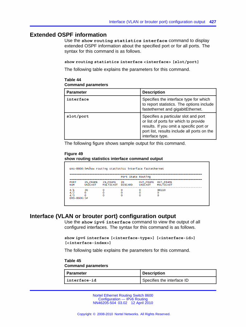
Interface (VLAN or brouter port) configuration output 427
Extended OSPF informationUse the show routing statistics interface command to displayextended OSPF information about the specified port or for all ports. Thesyntax for this command is as follows.
show routing statistics interface <interface> [slot/port]
The following table explains the parameters for this command.
Table 44Command parameters
Parameter Description
interface Specifies the interface type for whichto report statistics. The options includefastethernet and gigabitEthernet.
slot/port Specifies a particular slot and portor list of ports for which to provideresults. If you omit a specific port orport list, results include all ports on theinterface type.
The following figure shows sample output for this command.
Figure 49show routing statistics interface command output
Interface (VLAN or brouter port) configuration outputUse the show ipv6 interface command to view the output of allconfigured interfaces. The syntax for this command is as follows.
show ipv6 interface [<interface-type>] [<interface-id>][<interface-index>]
The following table explains the parameters for this command.
Table 45Command parameters
Parameter Description
interface-id Specifies the interface ID
Nortel Ethernet Routing Switch 8600Configuration — IPv6 Routing
NN46205-504 03.02 12 April 2010
Copyright © 2008-2010 Nortel Networks. All Rights Reserved.
.

428 NNCLI show commands
Table 45Command parameters (cont’d.)
Parameter Description
interface-index Specifies the index from 1–4096.
interface-type Specifies the type of interface if youwant to limit the output. The optionsare fastEthernet, gigabitEthernet,icmpstatistics, statistics, or vlan.
Figure 50 "show ipv6 interface" (page 428) shows sample output for thiscommand.
Figure 50show ipv6 interface
IPv6 static route informationUse the show ipv6 route command to display the existing IPv6 staticroutes for the switch or for a specific net or subnet. The syntax for thiscommand is as follows.
show ipv6 route static
Figure 51 "show ipv6 route static" (page 429) shows sample output for thiscommand.
Nortel Ethernet Routing Switch 8600Configuration — IPv6 Routing
NN46205-504 03.02 12 April 2010
Copyright © 2008-2010 Nortel Networks. All Rights Reserved.
.

MLD configuration 429
Figure 51show ipv6 route static
MLD cacheUse the show ipv6 mld-cache interface command to display theMLD cache for a brouter port, VLAN, or group address. The syntax for thiscommand is as follows.
show ipv6 mld-cache interface <interface-type> <interface-id>[grp-address <0-46>] [detail]
The following table explains the parameters for this command.
Table 46Command parameters
Parameter Description
grp-address Specifies the group address to display.
interface-id Specifies the interface ID.
interface-type Specifies the type of interface if youwant to limit the output. The optionsare fastEthernet, gigabitEthernet, orvlan.
MLD configurationUse the show ipv6 mld interface command to display configurationdetails for all MLD interfaces. The syntax for this command is as follows.
show ipv6 mld interface [<interface-type> <interface-id>][detail]
The following table explains the parameters for this command.
Nortel Ethernet Routing Switch 8600Configuration — IPv6 Routing
NN46205-504 03.02 12 April 2010
Copyright © 2008-2010 Nortel Networks. All Rights Reserved.
.

430 NNCLI show commands
Table 47Command parameters
Parameter Description
interface-id Specifies the interface ID.
interface-type Specifies the type of interface if youwant to limit the output. The optionsare fastEthernet, gigabitEthernet, orvlan.
Figure 52 "show ipv6 mld interface" (page 430) shows sample output forthis command.
Figure 52show ipv6 mld interface
Neighbor cacheUse the show ipv6 neighbor command to view entries in the neighborcache. The syntax for this command is as follows.
show ipv6 neighbor [<ipv6addr>] [type {other|dynamic|static|local}] [interface <interface-type> <interface-id>]
The following table explains the parameters for this command.
Table 48Command parameters
Parameter Description
interface-id Specifies the interface ID.
Nortel Ethernet Routing Switch 8600Configuration — IPv6 Routing
NN46205-504 03.02 12 April 2010
Copyright © 2008-2010 Nortel Networks. All Rights Reserved.
.

Neighbor discovery prefixes 431
Table 48Command parameters (cont’d.)
Parameter Description
interface-type Specifies the type of interface if youwant to limit the output. The optionsare fastEthernet, gigabitEthernet, orvlan.
type Specifies the type of mapping as oneof the following:• other
• dynamic
• static
• local
Figure 53 "show ipv6 neighbor" (page 431) shows sample output for theshow ipv6 neighbor command.
Figure 53show ipv6 neighbor
Neighbor discovery prefixesUse the show ipv6 nd-prefix interface command to view all configuredneighbor discovery prefixes. The syntax for this command is as follows.
show ipv6 nd-prefix interface <interface-type> <interface-id>]
The following table explains the parameters for this command.
Table 49Command parameters
Parameter Description
interface-id Specifies the interface ID.
interface-type Specifies the type of interface if youwant to limit the output. The optionsare fastEthernet, gigabitEthernet, orvlan.
Nortel Ethernet Routing Switch 8600Configuration — IPv6 Routing
NN46205-504 03.02 12 April 2010
Copyright © 2008-2010 Nortel Networks. All Rights Reserved.
.

432 NNCLI show commands
Figure 54 "show ipv6 nd-prefix interface" (page 432) shows sample outputfor the show ipv6 nd-prefix interface command.
Figure 54show ipv6 nd-prefix interface
OSPF areasUse the show ipv6 ospf area command to display information aboutOSPF area parameters. The syntax for this command is as follows.
show ipv6 ospf area
The following figure shows sample output for this command.
Figure 55show ipv6 ospf area
OSPF configuration settings for a portUse the show ip ospf interface command to display information aboutthe OSPF parameters of the specified port or all ports. The syntax for thiscommand is as follows.
Nortel Ethernet Routing Switch 8600Configuration — IPv6 Routing
NN46205-504 03.02 12 April 2010
Copyright © 2008-2010 Nortel Networks. All Rights Reserved.
.
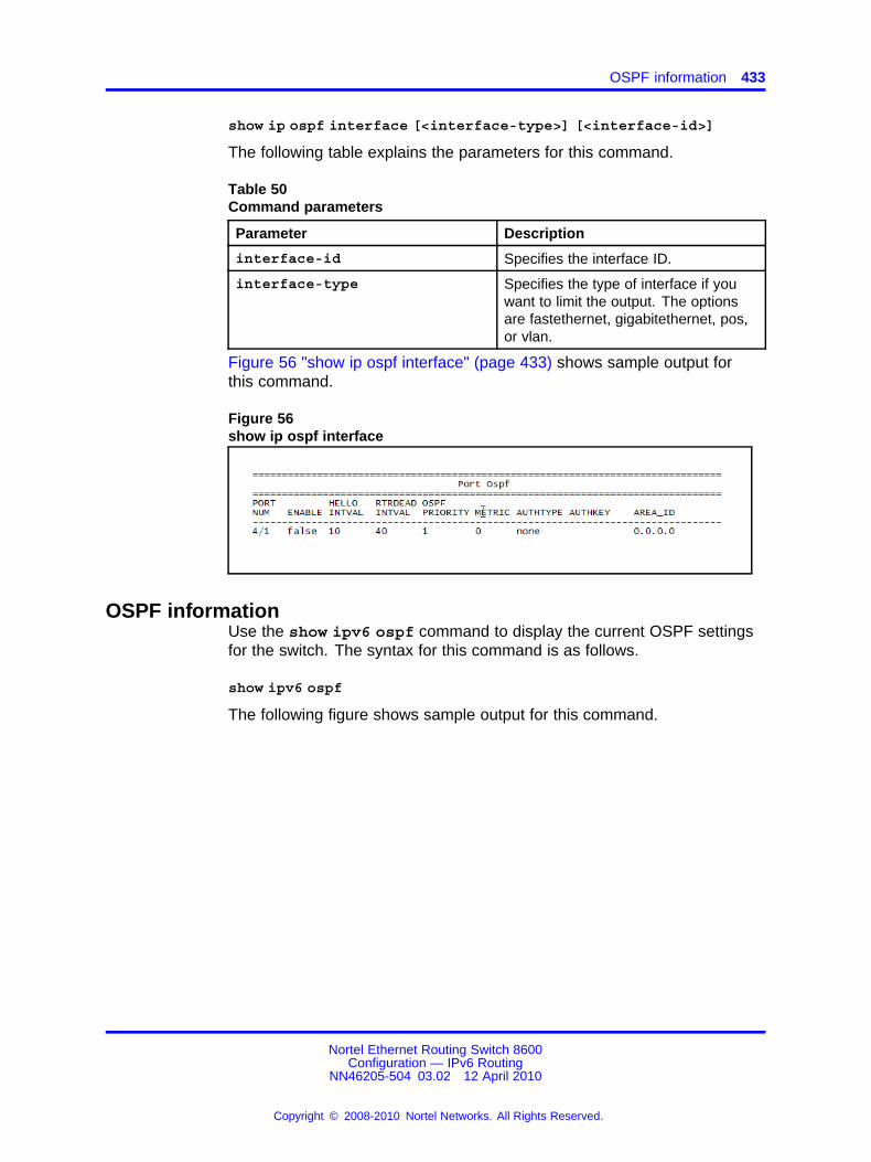
OSPF information 433
show ip ospf interface [<interface-type>] [<interface-id>]
The following table explains the parameters for this command.
Table 50Command parameters
Parameter Description
interface-id Specifies the interface ID.
interface-type Specifies the type of interface if youwant to limit the output. The optionsare fastethernet, gigabitethernet, pos,or vlan.
Figure 56 "show ip ospf interface" (page 433) shows sample output forthis command.
Figure 56show ip ospf interface
OSPF informationUse the show ipv6 ospf command to display the current OSPF settingsfor the switch. The syntax for this command is as follows.
show ipv6 ospf
The following figure shows sample output for this command.
Nortel Ethernet Routing Switch 8600Configuration — IPv6 Routing
NN46205-504 03.02 12 April 2010
Copyright © 2008-2010 Nortel Networks. All Rights Reserved.
.

434 NNCLI show commands
Figure 57show ipv6 ospf command output
OSPF interface informationUse the show ipv6 ospf interface command to display informationabout the OSPF interface.
show ipv6 ospf interface [{vlan|fastEthernet|gigabitEthernet}{vlan-id|slot/port}]
The following figure shows sample output for this command.
Figure 58show ipv6 ospf interface
OSPF interface timer settingsUse the show ipv6 ospf int-timers command to display OSPFinterface timer settings. The syntax for this command is as follows:
Nortel Ethernet Routing Switch 8600Configuration — IPv6 Routing
NN46205-504 03.02 12 April 2010
Copyright © 2008-2010 Nortel Networks. All Rights Reserved.
.

OSPF link-state database table 435
show ipv6 ospf int-timers
The following figure shows sample output for this command.
Figure 59show ipv6 ospf int-timers command output
OSPF link-state database tableUse the show ipv6 ospf lsdb command to display the OSPF link-statedatabase (LSDB) table. The syntax for this command is as follows.
show ipv6 ospf lsdb [scope <1-3>] [tunnel <1-2147483647>][area <A.B.C.D>] [lsa-type <1-8>] [adv-rtr <A.B.C.D>] [lsid<0-4294967295>] [detail]
You can specify a scope, VLAN, tunnel, area string, link-stateadvertisement type (0 to 5), link state ID, or advertising router. If youadd the detail option to the command, the output contains additionalinformation.
Figure 60 "show ipv6 ospf lsdb" (page 436) shows sample output with novariables for this command.
Nortel Ethernet Routing Switch 8600Configuration — IPv6 Routing
NN46205-504 03.02 12 April 2010
Copyright © 2008-2010 Nortel Networks. All Rights Reserved.
.

436 NNCLI show commands
Figure 60show ipv6 ospf lsdb
OSPF neighborsUse the show ipv6 ospf neighbor command to display OSPFneighbors configuration information. The syntax for this command is asfollows.
show ipv6 ospf neighbor
Figure 61 "show ipv6 ospf neighbor command output" (page 436) showssample command output for this command.
Figure 61show ipv6 ospf neighbor command output
OSPFv3 information for VLANsUse the show ip ospf interface command to view OSPFv3information for VLANs. The syntax for this command is as follows.
Nortel Ethernet Routing Switch 8600Configuration — IPv6 Routing
NN46205-504 03.02 12 April 2010
Copyright © 2008-2010 Nortel Networks. All Rights Reserved.
.

Tunnel information 437
show ip ospf interface vlan <vlan-id>
The following figure shows sample output for this command.
Figure 62show ip ospf interface
Tunnel informationUse the show ipv6 tunnel command to show general tunnel information.The syntax for this command is as follows.
show ipv6 tunnel [<tunnel-id>] [local <A.B.C.D>] [remote<A.B.C.D>] [detail]
The following table explains the parameters for this command.
Table 51Command parameters
Parameter Description
detail Displays address information inaddition to basic tunnel information.
tunnel-id Specifies the ID number of the tunnelin the range 1 through 2 147 483 647.
The following figure shows sample output for the show ipv6 tunnelcommand.
Nortel Ethernet Routing Switch 8600Configuration — IPv6 Routing
NN46205-504 03.02 12 April 2010
Copyright © 2008-2010 Nortel Networks. All Rights Reserved.
.
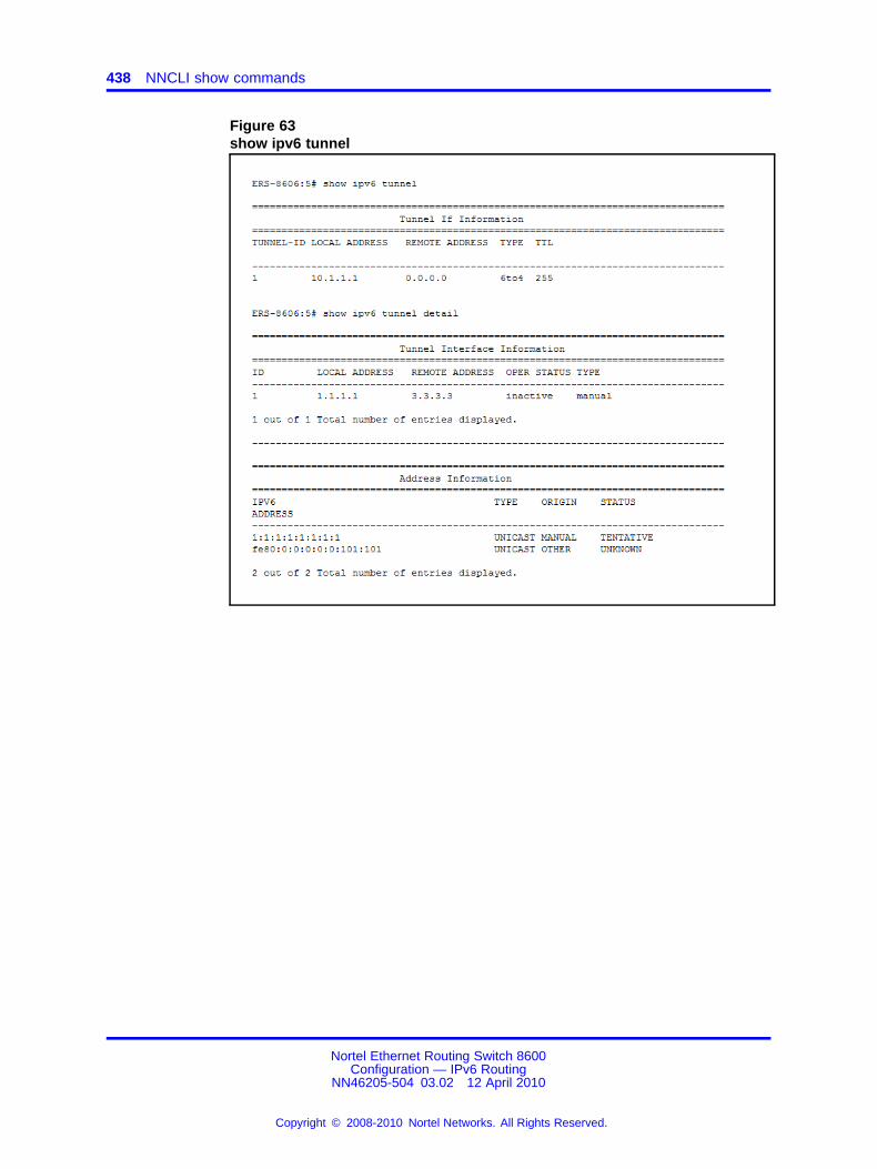
438 NNCLI show commands
Figure 63show ipv6 tunnel
Nortel Ethernet Routing Switch 8600Configuration — IPv6 Routing
NN46205-504 03.02 12 April 2010
Copyright © 2008-2010 Nortel Networks. All Rights Reserved.
.

439.
ICMPv6 type and codeThe Internet Control Message Protocol (ICMPv6) uses many messagesidentified by a type and code field (see RFC2463). Error messages usemessage types 0 to 127. Informational messages use message types 128to 255.
Table 52ICMPv6 type and code details
Type Name Code Reference
1 Destination Unreachable 0—no route to destination
1—communicationwith destinationadministrativelyprohibited
2—(not assigned)
3—address unreachable
4—port unreachable
RFC 2463
2 Packet Too Big N/A RFC 2463
3 Time Exceeded 0—hop limit exceeded intransit
1—fragment reassemblytime exceeded
RFC 2463
4 Parameter Problem 0—erroneous headerfield encountered
1—unrecognized NextHeader type encountered
2—unrecognized IPv6option encountered
RFC 2463
Nortel Ethernet Routing Switch 8600Configuration — IPv6 Routing
NN46205-504 03.02 12 April 2010
Copyright © 2008-2010 Nortel Networks. All Rights Reserved.
.
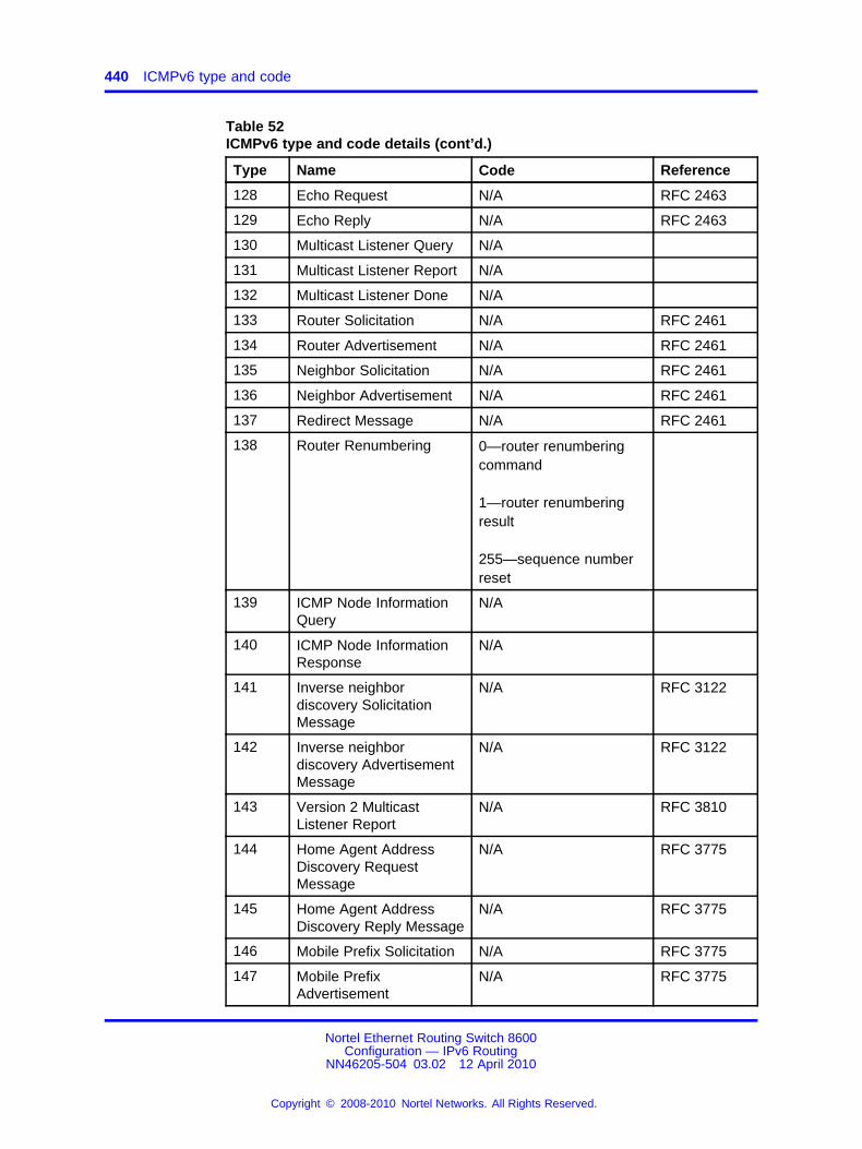
440 ICMPv6 type and code
Table 52ICMPv6 type and code details (cont’d.)
Type Name Code Reference
128 Echo Request N/A RFC 2463
129 Echo Reply N/A RFC 2463
130 Multicast Listener Query N/A
131 Multicast Listener Report N/A
132 Multicast Listener Done N/A
133 Router Solicitation N/A RFC 2461
134 Router Advertisement N/A RFC 2461
135 Neighbor Solicitation N/A RFC 2461
136 Neighbor Advertisement N/A RFC 2461
137 Redirect Message N/A RFC 2461
138 Router Renumbering 0—router renumberingcommand
1—router renumberingresult
255—sequence numberreset
139 ICMP Node InformationQuery
N/A
140 ICMP Node InformationResponse
N/A
141 Inverse neighbordiscovery SolicitationMessage
N/A RFC 3122
142 Inverse neighbordiscovery AdvertisementMessage
N/A RFC 3122
143 Version 2 MulticastListener Report
N/A RFC 3810
144 Home Agent AddressDiscovery RequestMessage
N/A RFC 3775
145 Home Agent AddressDiscovery Reply Message
N/A RFC 3775
146 Mobile Prefix Solicitation N/A RFC 3775
147 Mobile PrefixAdvertisement
N/A RFC 3775
Nortel Ethernet Routing Switch 8600Configuration — IPv6 Routing
NN46205-504 03.02 12 April 2010
Copyright © 2008-2010 Nortel Networks. All Rights Reserved.
.

441.
RFC reference for IPv6The following is a list of RFCs used in IPv6:
• RFC
• RFC 1812, Requirements for IP Version 4 Routers
• RFC 1881, IPv6 Address Allocation Management
• RFC 1886, DNS Extensions to support IP version 6
• RFC 1887, An Architecture for IPv6 Unicast Address Allocations
• RFC 1981, Path MTU Discovery for IP version 6
• RFC 2030, Simple Network Time Protocol (SNTP) v4 for IPv4, IPv6and OSI
• RFC 2373, IPv6 Addressing Architecture
• RFC 2375, IPv6 Multicast Address Assignments
• RFC 2385, Protection of BGP Sessions via the TCP MD5 SignatureOption
• RFC 2401, Security Architecture for the Internet Protocol
• RFC 2404, The Use of HMAC-SHA-1-96 within ESP and AH
• RFC 2406, IP Encapsulating Security Payload (ESP)
• RFC 2452,IP Version 6 Management Information Base for theTransmission Control Protocol
• RFC 2454, IP Version 6 Management Information Base for the UserDatagram Protocol
• RFC 2460, Internet Protocol, Version 6 (IPv6) Specification
• RFC 2461, Neighbor Discovery for IP Version 6 (IPv6)
• RFC 2462, IPv6 Stateless Address Autoconfiguration
• RFC 2463, Internet Control Message Protocol (ICMPv6) for the InternetProtocol Version 6 (IPv6) Specification
• RFC 2464, Transmission of IPv6 Packets over Ethernet Networks
Nortel Ethernet Routing Switch 8600Configuration — IPv6 Routing
NN46205-504 03.02 12 April 2010
Copyright © 2008-2010 Nortel Networks. All Rights Reserved.
.

442 RFC reference for IPv6
• RFC 2465, Management Information Base for IP Version 6: TextualConventions and General Group
• RFC 2466, Management Information Base for IP Version 6: ICMPv6Group
• RFC 2474, Definition of the Differential Services Field (DS Field) in theIPv4 and IPv6 Headers
• RFC 2526, Reserved IPv6 Subnet Anycast Addresses
• RFC 2710, Multicast Listener Discovery (MLD) for IPv6
• RFC 2740, OSPF for IPv6
• RFC 2893, Transition Mechanisms for IPv6 Hosts and Routers
• RFC 3019, IP Version 6 Management Information Base for TheMulticast Listener Discovery Protocol
• RFC 3056, Connection of IPv6 Domains via IPv4 Clouds
• RFC 3122, Extensions to IPv6 Neighbor Discovery for InverseDiscovery Specification
• RFC 3315, Dynamic Host Configuration Protocol for IPv6 (DHCPv6)
• RFC 3363, Representing Internet Protocol version 6 (IPv6) Addressesin the Domain Name System (DNS)
• RFC 3364, Tradeoffs in Domain Name System (DNS) Support forInternet Protocol version 6 (IPv6)
• RFC 3446, Anycast Rendevous Point (RP) mechanism using ProtocolIndependant Multicast (PIM) and Multicast Source Discovery Protocol(MSDP)
• RFC 3484, Default Address Selection for IPv6
• RFC 3513, Internet Protocol Version 6 (IPv6) Addressing Architecture
• RFC 3587, IPv6 Global Unicast Address Format
• RFC 3590, Source Address Selection for the Multicast ListenerDiscovery (MLD) Protocol
• RFC 3596, DNS Extensions to Support IP Version 6
• RFC 3618, Multicast Source Discovery Protocol (MSDP)
• RFC 3775, Mobility Support in IPv6
• RFC 3810, IPv6 Multicast capabilities
• RFC 4022, Management Information Base for the TransmissionControl Protocol (TCP)
• RFC 4087, IP Tunnel MIB
Nortel Ethernet Routing Switch 8600Configuration — IPv6 Routing
NN46205-504 03.02 12 April 2010
Copyright © 2008-2010 Nortel Networks. All Rights Reserved.
.

Tunnel information 443
• RFC 4113, Management Information Base for the User DatagramProtocol (UDP)
• RFC 4649, Dynamic Host Configuration Protocol for IPv6 (DHCPv6)Relay Agent Remote-ID Option
• draft-ietf-vrrp-ipv6-spec-08.txt, Virtual Router Redundancy Protocol forIPv6
Descriptions of management information bases (MIBs) in this documentare based on information from the listed RFCs.
Nortel Ethernet Routing Switch 8600Configuration — IPv6 Routing
NN46205-504 03.02 12 April 2010
Copyright © 2008-2010 Nortel Networks. All Rights Reserved.
.

444 RFC reference for IPv6
Nortel Ethernet Routing Switch 8600Configuration — IPv6 Routing
NN46205-504 03.02 12 April 2010
Copyright © 2008-2010 Nortel Networks. All Rights Reserved.
.


Nortel Ethernet Routing Switch 8600
Configuration — IPv6 RoutingRelease: 7.0Publication: NN46205-504Document revision: 03.02Document release date: 12 April 2010
Copyright © 2008-2010 Nortel Networks. All Rights Reserved.
While the information in this document is believed to be accurate and reliable, except as otherwise expressly agreed to in writingNORTEL PROVIDES THIS DOCUMENT "AS IS" WITHOUT WARRANTY OR CONDITION OF ANY KIND, EITHER EXPRESSOR IMPLIED. The information and/or products described in this document are subject to change without notice.
THE SOFTWARE DESCRIBED IN THIS DOCUMENT IS FURNISHED UNDER A LICENSE AGREEMENT AND MAY BE USEDONLY IN ACCORDANCE WITH THE TERMS OF THAT LICENSE.
Nortel, Nortel Networks, the Nortel logo, and the Globemark are trademarks of Nortel Networks.
Linux is a trademark of Linus Torvalds.
Microsoft, Windows, Windows XP, and Windows NT are trademarks of Microsoft Corporation.
All other trademarks are the property of their respective owners.
To provide feedback or to report a problem in this document, go to www.nortel.com/documentfeedback.
www.nortel.com