
Configuring use case models in product families
31
Noname manuscript No. (will be inserted by the editor) Configuring use case models in product families Ines Hajri · Arda Goknil · Lionel C. Briand · Thierry Stephany the date of receipt and acceptance should be inserted later Abstract In many domains such as automotive and avion- ics, the size and complexity of software systems is quickly increasing. At the same time, many stakeholders tend to be involved in the development of such systems, which typi- cally must also be configured for multiple customers with varying needs. Product Line Engineering (PLE) is there- fore an inevitable practice for such systems. Furthermore, because in many areas requirements must be explicit and traceability to them is required by standards, use cases and domain models are common practice for requirements elici- tation and analysis. In this paper, based on the above obser- vations, we aim at supporting PLE in the context of use case- centric development. Therefore, we propose, apply, and as- sess a use case-driven configuration approach which interac- tively receives configuration decisions from the analysts to generate Product Specific (PS) use case and domain models. Our approach provides the following: (1) a use case-centric product line modeling method (PUM), (2) automated, inter- active configuration support based on PUM, and (3) an au- tomatic generation of PS use case and domain models from Product Line (PL) models and configuration decisions. The approach is supported by a tool relying on Natural Language Processing (NLP), and integrated with an industrial require- ments management tool, i.e., IBM Doors. We successfully applied and evaluated our approach to an industrial case study in the automotive domain, thus showing evidence that the approach is practical and beneficial to capture variability at the appropriate level of granularity and to configure PS use case and domain models in industrial settings. Ines Hajri, Arda Goknil, and Lionel C. Briand SnT Centre for Security, Reliability and Trust, University of Luxem- bourg, Luxembourg Thierry Stephany International Electronics & Engineering (IEE), Contern, Luxembourg E-mail: {ines.hajri, arda.goknil, lionel.Briand}@uni.lu [email protected] 1 Introduction In various domains such as automotive and avionics, soft- ware systems are quickly getting larger and more complex. These systems often consist of various interacting subsys- tems, e.g., lighting systems, engine controller, and sensing systems. Further, many suppliers are typically involved in system development. Each supplier is mostly specialized in developing one or two of these subsystems. For example, in the automotive domain, while one supplier provides a sensing system monitoring the driver seat for occupancy by means of a pressure sensitive sensor, another supplier may develop an engine controller using the output of the sens- ing system to prevent unintentional vehicle starts and un- necessary fuel consumption. These suppliers develop multi- ple versions of the same product since they work with many manufacturers (customers). Therefore, given the complex- ity arising from the context described above, systematic and supported Product Line Engineering (PLE) is crucial in their software development practice, from requirements analysis to implementation and testing. Our work was motivated by discussions with IEE S.A. (in the following “IEE”) [3], a leading supplier in automo- tive sensing systems enhancing safety and comfort in vehi- cles produced by major car manufacturers worldwide. Such systems monitor the physical environment by means of phys- ical components (e.g., electrical field sensors, pressure sen- sitive sensors, and force sensing resistors), detect events or changes in the existence of objects and humans (e.g., seat occupant classification, gesture recognition, and driver pres- ence detection), and provide the corresponding output to other subsystems (e.g., airbag control unit, trunk controller, and engine controller). At IEE, similar to many other de- velopment environments, use cases (including use case di- agrams and use case specifications) are the main artifacts employed to elicit requirements and communicate with cus-
Transcript of Configuring use case models in product families
Noname manuscript No.(will be inserted by the editor)
Configuring use case models in product families
Ines Hajri · Arda Goknil · Lionel C. Briand · Thierry Stephany
the date of receipt and acceptance should be inserted later
Abstract In many domains such as automotive and avion-ics, the size and complexity of software systems is quicklyincreasing. At the same time, many stakeholders tend to beinvolved in the development of such systems, which typi-cally must also be configured for multiple customers withvarying needs. Product Line Engineering (PLE) is there-fore an inevitable practice for such systems. Furthermore,because in many areas requirements must be explicit andtraceability to them is required by standards, use cases anddomain models are common practice for requirements elici-tation and analysis. In this paper, based on the above obser-vations, we aim at supporting PLE in the context of use case-centric development. Therefore, we propose, apply, and as-sess a use case-driven configuration approach which interac-tively receives configuration decisions from the analysts togenerate Product Specific (PS) use case and domain models.Our approach provides the following: (1) a use case-centricproduct line modeling method (PUM), (2) automated, inter-active configuration support based on PUM, and (3) an au-tomatic generation of PS use case and domain models fromProduct Line (PL) models and configuration decisions. Theapproach is supported by a tool relying on Natural LanguageProcessing (NLP), and integrated with an industrial require-ments management tool, i.e., IBM Doors. We successfullyapplied and evaluated our approach to an industrial casestudy in the automotive domain, thus showing evidence thatthe approach is practical and beneficial to capture variabilityat the appropriate level of granularity and to configure PSuse case and domain models in industrial settings.
Ines Hajri, Arda Goknil, and Lionel C. BriandSnT Centre for Security, Reliability and Trust, University of Luxem-bourg, LuxembourgThierry StephanyInternational Electronics & Engineering (IEE), Contern, LuxembourgE-mail: {ines.hajri, arda.goknil, lionel.Briand}@[email protected]
1 Introduction
In various domains such as automotive and avionics, soft-ware systems are quickly getting larger and more complex.These systems often consist of various interacting subsys-tems, e.g., lighting systems, engine controller, and sensingsystems. Further, many suppliers are typically involved insystem development. Each supplier is mostly specialized indeveloping one or two of these subsystems. For example,in the automotive domain, while one supplier provides asensing system monitoring the driver seat for occupancy bymeans of a pressure sensitive sensor, another supplier maydevelop an engine controller using the output of the sens-ing system to prevent unintentional vehicle starts and un-necessary fuel consumption. These suppliers develop multi-ple versions of the same product since they work with manymanufacturers (customers). Therefore, given the complex-ity arising from the context described above, systematic andsupported Product Line Engineering (PLE) is crucial in theirsoftware development practice, from requirements analysisto implementation and testing.
Our work was motivated by discussions with IEE S.A.(in the following “IEE”) [3], a leading supplier in automo-tive sensing systems enhancing safety and comfort in vehi-cles produced by major car manufacturers worldwide. Suchsystems monitor the physical environment by means of phys-ical components (e.g., electrical field sensors, pressure sen-sitive sensors, and force sensing resistors), detect events orchanges in the existence of objects and humans (e.g., seatoccupant classification, gesture recognition, and driver pres-ence detection), and provide the corresponding output toother subsystems (e.g., airbag control unit, trunk controller,and engine controller). At IEE, similar to many other de-velopment environments, use cases (including use case di-agrams and use case specifications) are the main artifactsemployed to elicit requirements and communicate with cus-
tomers. In order to clarify the terminology used in the re-quirements and to provide a common understanding of theapplication domain concepts, use cases are often accompa-nied by a domain model formalizing concepts and their re-lationships, often under the form of a class diagram withconstraints.
For each new product family, it is common to start adevelopment project with an initial customer providing re-quirements for a single product. The analysts elicit and doc-ument the initial product requirements as use cases and adomain model. The use cases and domain model are copied,modified, and then maintained for each new customer. Thispractice is called clone-and-own reuse [25] and requires theentire use cases and domain model to be evaluated man-ually to identify changes since nothing indicates what thevariable requirements are and where they are located. Theclone-and-own approach is fully manual, error-prone, andtime-consuming in industrial practice. Therefore, more ef-ficient and automated techniques are required to managereuse of common and variable requirements given as usecases and domain model across products in a product line.One significant step in that direction is automated configu-ration that aims at guiding configuration decisions for Prod-uct Line (PL) use cases and domain model. In our context,the analysts explicitly specify PL variability, and automati-cally generate Product Specific (PS) use cases and domainmodel for a configured product. This is expected, in the con-text of use case-driven development, to facilitate the reuse ofuse case models for multiple products. After assessing rel-evant techniques in the literature, we developed a completeuse case-driven configuration approach supporting embed-ded system development, though we expect it to be easilyapplicable in other contexts. We target, to the largest extentpossible, common software modeling practices, to achievewidespread applicability.
The benefits of use case-driven configuration have beenacknowledged and there are proposed approaches in the lit-erature [9,61,6]. Many studies [34,27,8] provide configura-tion approaches which require that feature models be tracedas an orthogonal model to artifacts such as UML use case,activity and class diagrams. In order to employ these ap-proaches in industrial practice, the analysts need to providefeature models with their traces to use cases and related ar-tifacts. The evolution of feature models also requires thesetraces to be maintained manually by the analysts. Due todeadline pressure and limited resources, many software de-velopment companies find such additional traceability andmaintainability effort to be impractical. Moon et al. [53,52]propose a method that generates PS use cases from PL usecases without using any feature model. However, the pro-posed method requires Primitive Requirements (PR) (i.e.,building blocks of complex requirements) to be specified bythe analysts and traced to the use case diagram and specifi-
cations via PR - Context and PR - Use Case matrices. Theconfiguration takes place by selecting the PRs in the matri-ces without any automated guidance.
To avoid, or at least minimize, additional traceability andmaintenance effort required by the approaches in the litera-ture, we first need a modeling method with which we canmodel variability information explicitly in the use case dia-gram, specifications, and domain model, without additionalartifacts. Therefore, in our previous work [44], which thispaper extends, we proposed and assessed the Product lineUse case modeling Method (PUM), which enables the an-alysts to capture and document variability in PL use casediagrams, use case specifications, and domain models. ForPL use case diagrams, we employ the diagram extensionsproposed by Halmans and Pohl [45]. These extensions over-come the shortcomings of textual representations of vari-ability, such as implicit variants and variation points. Fur-ther, for PL use case specifications, we employ RestrictedUse Case Modeling (RUCM) [79], which includes a tem-plate and restriction rules to reduce imprecision and incom-pleteness in use cases. RUCM was a clear choice since itreduces ambiguity and facilitates automated analysis of usecases [78,80,73,74]. However, since it was not originallymeant to model variability, we introduced some PL exten-sions to capture variability in use case specifications [44].To be able to capture variability in PL domain models, werely on the stereotypes (i.e., variation, variant and optional),proposed by Ziadi and Jezequel [82] for UML class dia-grams.
In this paper, we propose, apply, and assess a use case-driven configuration approach based on PUM. Our goal isto provide a degree of configuration automation that enableseffective product-line management in use case-driven de-velopment, without requiring additional modeling artifactsand traceability effort. Our approach supports four activities.First, the analysts model the variability information explic-itly in a PL use case diagram, its use case specifications, andits corresponding domain model. Second, the consistency ofthe PL use case diagram and specifications are checked andinconsistencies are reported if there are any. For instance, avariation point in the use case diagram might be missing inthe corresponding use case specification or a use case spec-ification may not conform to the extended RUCM template.Third, the analyst is guided to make configuration decisionsbased on variability information in the PL models. The par-tial order of decisions to be made is automatically identifiedfrom the dependencies among variation points and variantuse cases. In the case of contradicting configuration deci-sions, such as two decisions resulting in selecting variantuse cases violating some dependency constraints, we au-tomatically detect and report them. The analyst must thenbacktrack and revise the decisions to resolve these inconsis-tencies. Alternatively, we could employ constraint solvers
(i.e., SAT solver, BDD solver and Prolog solver) to identifya priori possible contradicting decisions so as to avoid them.However, according to our observation at IEE, customers arealso involved in the decision-making process in which theyfrequently re-evaluate, backtrack and revise their decisions.Therefore, it is important for them to have the possibilityto make contradicting decisions and revise prior ones as aresult. Fourth, based on configuration decisions, the PS usecase and domain models are generated from the PL use caseand domain models. To support these activities, we devel-oped a tool, PUMConf (Product line Use case Model Con-figurator). The tool automatically checks the consistency ofthe PL models, identifies the partial order of decisions to bemade, determines contradicting decisions, and generates PSuse case and domain models. To summarize, the contribu-tions of this paper are:
– a configuration approach that is specifically tailored touse case-driven development, and that guides the ana-lysts and customers in making configuration decisionsin product lines to automatically generate PS use caseand domain models;
– tool support integrated with an industrial requirementsmanagement tool (i.e., IBM Doors) as a plug-in, whichrelies on Natural Language Processing (NLP) to reportinconsistencies in PL use case models and contradict-ing configuration decisions, and to automatically gener-ate PS use case and domain models;
– an industrial case study demonstrating the applicabilityand benefits of our configuration approach.
This paper is structured as follows. Section 2 introducesthe industrial context of our case study to illustrate the prac-tical motivations for our configuration approach. Section 3discusses the related work in light of our needs. In Section 4,we provide an overview of the approach. Section 5 providesa brief description of PL use case and domain modelingproposed in our previous work, which this paper extends.In Section 6, we illustrate our approach through examplemodels. In Sections 7 and 8, we provide the details of thecore technical parts of our approach: consistency checkingof configuration decisions and generation of PS use case anddomain models. Section 9 presents our (publicly available)tool support for configuration, while Section 10 presents ourindustrial case study, involving an embedded system calledSmart Trunk Opener (STO), along with results and lessonslearned. We conclude the paper in Section 11.
2 Motivation and Context
Our configuration approach is developed for the context ofembedded software systems, interacting with multiple otherexternal systems, and developed according a use case-driven
process, by a supplier for multiple manufacturers (customers).In such a context, requirements variability is communicatedto customers and an interactive configuration process is fol-lowed for which guidance and automated support are needed.For instance, for each product in a product family, IEE ne-gotiates with customers how to resolve variation points inrequirements, in other words how to configure the productline.
In this paper, we use Smart Trunk Opener (STO) as acase study, to motivate and assess our approach. STO is areal-time automotive embedded system developed by IEE.It provides automatic, hands-free access to a vehicle’s trunk,in combination with a keyless entry system. In possessionof the vehicle’s electronic remote control, the user movesher leg in a forward and backward direction at the vehicle’srear bumper. STO recognizes the movement and transmits asignal to the keyless entry system, which confirms that theuser has the remote. This allows the trunk controller to openthe trunk automatically.
STO Requirements from Customer A
(Use Case Diagram and Specifications, and Domain Model)
Customer Afor STO
evolves to
(clone-and-own)
modify
STO Requirements from Customer B
(Use Case Diagram and Specifications, and Domain Model)
modify
evolves to
(clone-and-own)
STO Requirements from Customer C
(Use Case Diagram and Specifications, and Domain Model)
modify
Customer Bfor STO
Customer Cfor STO
Fig. 1 Clone-and-Own Reuse at IEE for a Product Family
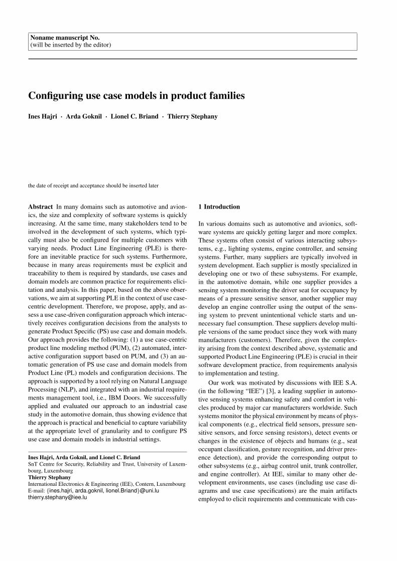
The current use case-driven development practice at IEE,like in many other environments, is based on clone-and-ownreuse [25] (see Fig. 1). IEE starts a project with an initialcustomer. The product requirements are elicited from theinitial customer and documented as a use case diagram, usecase specifications, and a domain model. For each new cus-tomer in the product family, the IEE analysts need to clonethe current models, and negotiate variabilities with the cus-tomer to produce a new use case diagram, set of specifica-tions, and domain model (see clone-and-own in Fig. 1). Asa result of the negotiations, the IEE analysts make changesin the cloned models (see modify). With such practice, vari-ants and variation points (i.e., where potential changes aremade) are not documented and IEE analysts, together withthe customer, need to evaluate the entire use cases and do-main model.
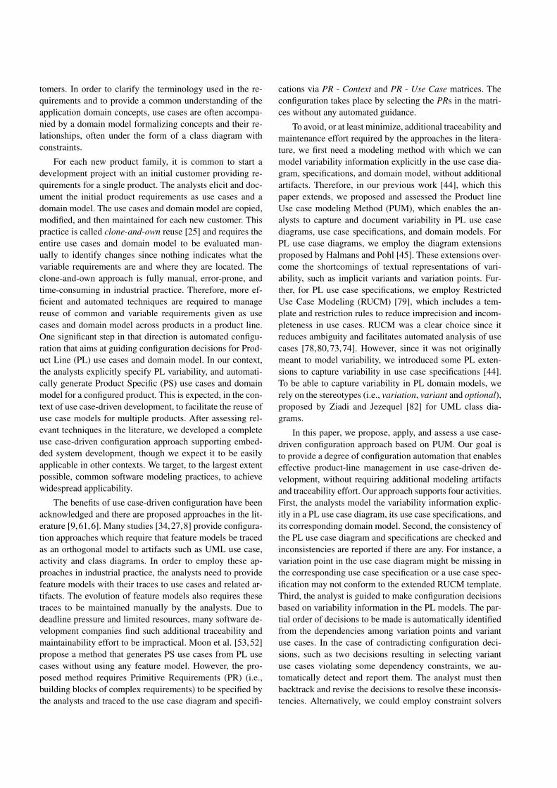
Fig. 2 depicts part of the initial UML use case diagramof the STO product, which describes four main functions:recognize gesture, provide system operating status, clear er-ror status, and provide system user data.
In the clone-and-own reuse, the initial diagram formsthe baseline to negotiate the STO requirements with otherpotential customers. For instance, a second customer couldrequire all use cases except Store Error Status, Clear Error
STO System
Sensors
STO Controller
Recognize Gesture
Identify System Operating Status
Tester Provide System User Data
<<include>>Store Error
Status
<<include>>
Clear Error Status
Provide System User Data via
Standard Mode
Provide System User Data via IEE
QC Mode
<<extend>>
Clear Error Status via Diagnostic
Mode
Clear Error Status via IEE
QC Mode
<<extend>>
<<extend>>
<<extend>>
Provide System Operating Status
<<include>>
Fig. 2 Part of the UML Use Case Diagram for STO
Status, and two use cases extending Clear Error Status. Athird customer could need another method of providing sys-tem user data as a new use case Provide System User Datavia Diagnostic Mode, which extends Provide System UserData but does not exist in the initial diagram in Fig. 2. TheIEE analysts need to clone the diagram for each new cus-tomer, negotiate the diagram changes with the customer, andthen modify it.
One solution to automate the current practice is to havePL use cases in which variability information is explicitlyrepresented. A configurator can guide the analysts and cus-tomers to automatically generate PS use cases by processingthe variability information in PL use cases. However, UMLdoes not allow to explicitly represent variability informa-tion in the diagram, e.g., which use cases are mandatory andwhich ones are variant. For instance, in Fig. 2, there are threevariation points: Clear Error Status, Store Error Status, andProvide System User Data. Clear Error Status and Store Er-ror Status are optional while Provide System User Data ismandatory. We also need to represent cardinality constraintsover these variation points, i.e., the number of variants tobe chosen. For instance, there are at least three ways of op-erationalizing Provide System User Data: Provide SystemUser Data via Diagnostic Mode is optional while the othertwo are mandatory. In addition, there are dependencies be-tween variation points, e.g., having Store Error Status in anSTO product requires having Clear Error Status in the sameproduct.
A use case diagram is accompanied by a set of use casespecifications providing detailed use case descriptions. Theconfiguration also has to take into account these detailed de-scriptions since some variability information (e.g., optionaluse case steps and flows) cannot be captured in a use case di-agram but only in specifications. However, a use case spec-ification usually conforms to a standard use case templatewhich, in general, does not provide any means to documentvariability information [26,47,10]. Capturing the most pop-
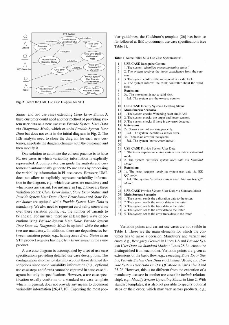
ular guidelines, the Cockburn’s template [26] has been sofar followed at IEE to document use case specifications (seeTable 1).
Table 1 Some Initial STO Use Case Specifications
1 USE CASE Recognize Gesture2 1. The system ‘identifies system operating status’.3 2. The system receives the move capacitance from the sen-
sors.4 3. The system confirms the movement is a valid kick.5 4. The system informs the trunk controller about the valid
kick.6 Extensions7 3a. The movement is not a valid kick.8 3a1. The system sets the overuse counter.910 USE CASE Identify System Operating Status11 Main Success Scenario12 1. The system checks Watchdog reset and RAM.13 2. The system checks the upper and lower sensors.14 3. The system checks if there is any error detected.15 Extensions16 2a. Sensors are not working properly.17 2a1. The system identifies a sensor error.18 3a. There is an error in the system.19 3a1. The system ‘stores error status’.2021 USE CASE Provide System User Data22 1. The tester requests receiving system user data via standard
mode.23 2. The system ‘provides system user data via Standard
Mode’.24 Extensions25 1a. The tester requests receiving system user data via IEE
QC mode.26 1a1. The system ‘provides system user data via IEE QC
Mode’.2728 USE CASE Provide System User Data via Standard Mode29 Main Success Scenario30 1. The system sends the calibration data to the tester.31 2. The system sends the sensor data to the tester.32 3. The system sends the trace data to the tester.33 4. The system sends the error data to the tester.34 5. The system sends the error trace data to the tester.
Variation points and variant use cases are not visible inTable 1. These are the main elements for which the cus-tomer has to make a decision. Mandatory and variant usecases, e.g., Recognize Gesture in Lines 1-8 and Provide Sys-tem User Data via Standard Mode in Lines 28-34, cannot bedistinguished from each other. Variation points are given asextensions of the basic flow, e.g., executing Store Error Sta-tus, Provide System User Data via Standard Mode, and Pro-vide System User Data via IEE QC Mode in Lines 18-19 and25-26. However, this is no different from the execution of amandatory use case in another use case (the include relation-ship), e.g., Identify System Operating Status in Line 2. Withstandard templates, it is also not possible to specify optionalsteps or their order, which may vary across products, e.g.,
the steps in Lines 30-34 which are optional with a variantorder. Without explicit variability information, the analystsmanually clone the specifications, evaluate the entire docu-mentation to negotiate potential changes with the customer,and finally update the cloned specifications. For instance, fora new customer asking a diagnostic mode, the IEE analystsmanually add a new use case specification Provide SystemUser Data via Diagnostic Mode and yet another extensionto Provide System User Data (see Lines 24-26). On the otherhand, if the same customer does not require calibration andsensor data to be sent to the tester in the standard mode, theanalysts need to manually delete the corresponding use casesteps from Provide System User Data via Standard Mode(Lines 30 and 31).
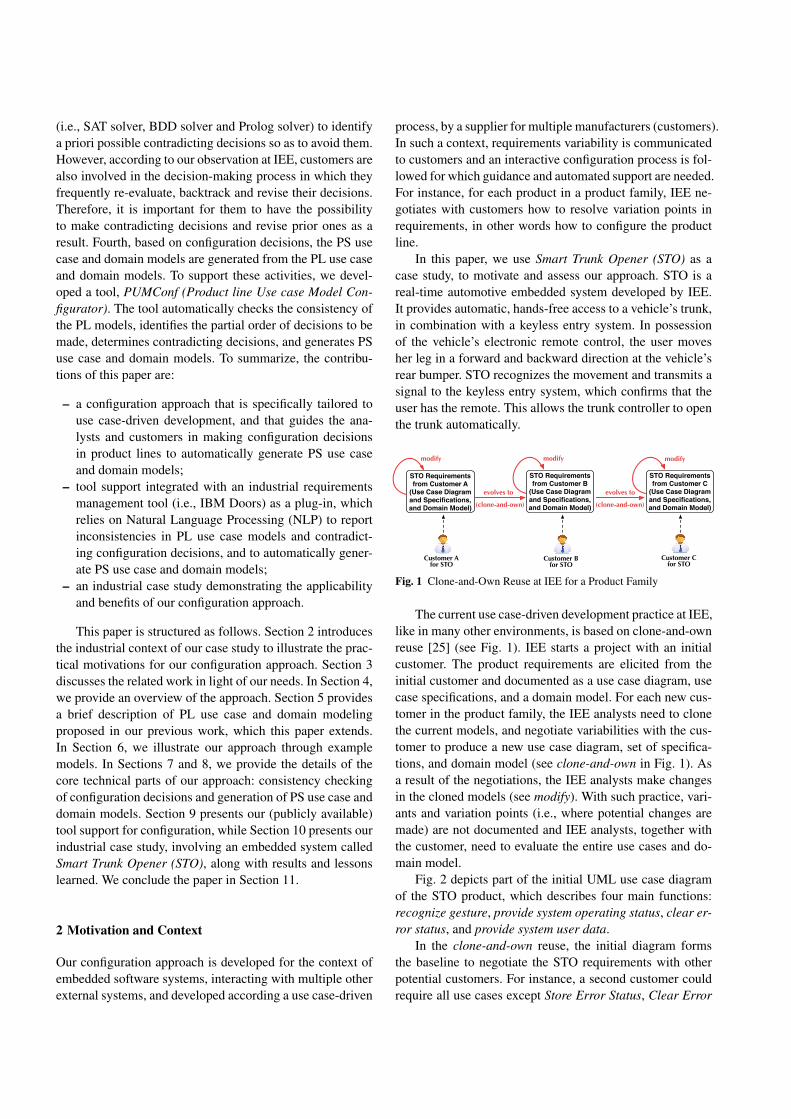
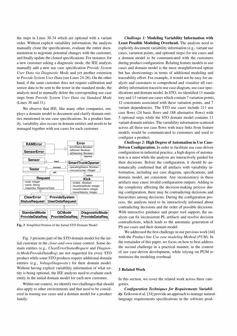
We observe that IEE, like many other companies, em-ploys a domain model to document and clarify domain enti-ties mentioned in use case specifications. In a product fam-ily, variability also occurs in domain entities and needs to bemanaged together with use cases for each customer.
Request- code: integer- name: String- response: ResponseType
Sensor
Tester1
ClearErrorStatusRequest
Error- errorStatus:Boolean- isStored: Boolean- isDetected: Boolean
itserrors*
SmartTrunkOpener- operatingStatus: Boolean- overuseCounter: integer
1
ProvideSystem UserDataRequest
Kick- isValid : Boolean- moveAmplitude: integer- moveDuration: integer- moveVelocity: integer
1
input
connect
itsKick
12
1 1
*ask
SensorError
RAMError
StandardModeProvideDataReq
QCModeProvideDataReq
DiagnosticModeProvideDataReq
Fig. 3 Simplified Portion of the Initial STO Domain Model
Fig. 3 presents part of the STO domain model for the ini-tial customer in the clone-and-own reuse context. Some do-main entities (e.g., ClearErrorStatusRequest and Diagnos-ticModeProvideDataReq) are not requested for every STOproduct while some STO products require additional domainentities (e.g., VoltageDiagnostic) for their domain model.Without having explicit variability information of what en-tity is being optional, the IEE analysts need to evaluate eachentity in the initial domain model for each new customer.
Within our context, we identify two challenges that shouldalso apply to other environments and that need to be consid-ered in reusing use cases and a domain model for a productfamily:
Challenge 1: Modeling Variability Information withLeast Possible Modeling Overhead. The analysts need toexplicitly document variability information (e.g., variant usecases, variation points, and optional steps) for use cases anda domain model to be communicated with the customersduring product configuration. Relating feature models to usecases and domain model is the most straightforward optionbut has shortcomings in terms of additional modeling andtraceability effort. For example, it would not be easy for an-alysts and customers to comprehend and visualize all vari-ability information traced to use case diagram, use case spec-ifications and domain model. In STO, we identified 11 manda-tory and 13 variant use cases which contain 7 variation points,12 constraints associated with these variation points, and 7variant dependencies. The STO use cases include 211 usecase flows (24 basic flows and 188 alternative flows) with5 optional steps while the STO domain model contains 11variant domain entities. The variability information scatteredacross all these use case flows with trace links from featuremodels would be communicated to customers and used toconfigure a product.
Challenge 2: High Degree of Automation in Use Case-Driven Configuration. In order to facilitate use case-drivenconfiguration in industrial practice, a high degree of automa-tion is a must while the analysts are interactively guided fortheir decisions. Before the configuration, it should be au-tomatically confirmed that all artifacts with variability in-formation, including use case diagram, specifications, anddomain model, are consistent. Any inconsistency in theseartifacts may cause invalid configuration outputs. Adding tothe complexity affecting the decision-making process dur-ing configuration, there may be contradicting decisions andhierarchies among decisions. During the configuration pro-cess, the analysts need to be interactively informed aboutcontradicting decisions and the order of possible decisions.With interactive guidance and proper tool support, the an-alysts can fix inconsistent PL artifacts and resolve decisioncontradictions, which leads to the automatic generation ofPS use cases and their domain model.
We addressed the first challenge in our previous work [44]with the Product line Use case modeling Method (PUM). Inthe remainder of this paper, we focus on how to best addressthe second challenge in a practical manner, in the contextof use case-driven development, while relying on PUM tominimize the modeling overhead.
3 Related Work
In this section, we cover the related work across three cate-gories.
Configuration Techniques for Requirements Variabil-ity. Eriksson et al. [34] provide an approach to manage natural-language requirements specifications in the software prod-
uct line context. Variability is captured and managed usinga feature model while requirements in various forms, e.g.,use cases, textual requirements specifications and domainmodel, are traced to the feature model. The analyst selectsthe features in the feature model to be included in the prod-uct. By following traces from the selected features to therequirements, the approach filters those requirements thatare relevant for a specific product in the product line. Thesefiltered requirements are then exported as product require-ments specifications. The approach does not support any au-tomated decision-making solution (e.g., decision ordering,decision consistency checking, and inferring decisions) forselecting features (Challenge 2). In addition, the analyst hasto manually assign traces between features and requirementsat a very low level of granularity, i.e., sequences of use casesteps (Challenge 1). pure::variants [5] is a tool to manageall parts of software products with their components, re-strictions and terms of usage. Its extension, pure::variantsfor IBM DOORS [4], enables the analyst to capture vari-ability as features in a feature model, and trace them to re-quirements specifications in IBM DOORS. It transforms therequirements specifications into product requirements basedon the selected features in the feature model. Compared tothe approach proposed by Eriksson et al. [34], pure::variantsfor IBM DOORS provides a better automated support, i.e.,an automated contradiction detection for feature models. How-ever, the analyst still suffers from the same modeling over-head, when pure::variants is employed. The analyst needsto manually establish traces at a very low level granular-ity and maintain these traces when the feature model or re-quirements specifications evolve. There are many similarapproaches, eg., [42,24,22,7,21], which require modelingand maintenance overhead with poor automated configura-tion support. Our configuration approach attempts to min-imize this overhead by capturing variability information inuse case and domain models (Challenge 1).
Moon et al. [53,52] propose a method that generatesPS use cases from PL use cases without using any featuremodel. However, the proposed method requires that Prim-itive Requirements (PR) (i.e., building blocks of complexrequirements) be specified by the analyst and traced to theuse case diagram and specifications via the PR - Context andPR - Use Case matrices. The analyst has to manually encodetraceability information in these matrices (Challenge 1). Theconfiguration takes place by selecting the PRs in the matri-ces without any automated decision-making support (Chal-lenge 2).
John and Muthig [46] introduce some product line ex-tensions to use case diagrams and specifications to be ableto capture variant use cases without a feature model. Theypropose a new artifact, called decision model, to representvariation points textually in a tabular form. Each variationpoint has multiple facts which represent decisions. For each
decision, there are actions which describe configuration op-erations for use cases, e.g., removing parts of a use case.The analyst is expected to configure, with the help of thedecision model, the product specific use case diagram andspecifications but such a decision model can quickly becometoo complex for the analyst to comprehend. There is no au-tomated tool support reported for the approach (Challenge2). Faulk [37] proposes the use of a similar decision modelto generate PS requirements specifications from PL require-ments specifications. Biddle et al. [16] provide support forconfiguring use case specifications through parametrization.Parameters can be specified anywhere in the name or bodyof a parameterized use case. The manual assignment of val-ues to parameters is considered as configuring product spe-cific use case specifications (Challenge 2). Fantechi et al. [36,35] propose Product Line Use Cases (PLUC), an extensionof the Cockburn use case template with three kinds of tags(i.e., alternative, parametric, and optional). It is not possiblewith these tags to explicitly represent mandatory and op-tional variants. Variants and variation points are hidden inuse case specifications conforming to PLUC. These two ap-proaches [16,36] do not support variability in the use casediagram and domain model. They also lack automated sup-port for the decision-making process including decision or-dering and detection of contradicting decisions (Challenge2).
Annotation- and Composition-based Configuration forScenario-based Requirements. Some approaches specializein configuring scenario-based requirements using annotation-and composition-based techniques [6]. The Product Line Usecase modeling for Systems and Software engineering ap-proach (PLUSS) proposed by Eriksson et al. [34,32,33] usesfeature models to configure requirements in multiple formsincluding scenario-based requirements models (e.g., use casesand activity diagrams). PLUSS employs annotations through-out requirements to represent how they are related to fea-tures. Czarnecki and Antkiewicz [27] propose another con-figuration approach based on annotation of scenarios usingfeature models. Activity diagrams are used to specify sce-narios. Traces between feature models and activity diagramsare given as special annotations on activity diagrams. To an-notate activity diagrams, the approach employs model tem-plates, which contain the union of the model elements, e.g.,presence conditions and meta-expressions, in all valid tem-plate instances, i.e., annotated activity diagrams. A productis specified by creating a feature configuration based on thefeature model. The model template is instantiated automati-cally by using the feature configuration. The generated tem-plate instance is an activity diagram of the specified prod-uct. Although the template instantiation is automated, fea-ture configuration is manual (Challenge 2). The analyst alsohas to manually create a feature model and a model templatefor annotations.
Bonifacio et al. [20,18] propose a framework for model-ing the composition process of scenario variability mecha-nisms (MSVCM). They provide a weaver (configurator) thattakes a PL use case model, a feature model, a product con-figuration, and configuration knowledge as input. The prod-uct configuration artifact identifies a specific product, whichis characterized by a configuration of features in the featuremodel, while the configuration knowledge relates featuresto transformations used for automatically generating the PSuse case model. These two artifacts are manually created bythe analyst (Challenge 2). The Variability Modeling Lan-guage for Requirements (VML4RE) [8,83] presents a sim-ilar solution for the composition of use case diagrams andtheir selected scenarios represented by activity diagrams.It supports the definition of traces between feature modelsand requirements (e.g., use case diagram and activity dia-gram). VML4RE provides a simple set of operators to spec-ify the composition of requirements models for generatingPS requirements models. There are more composition-basedapproaches [71,54,17] to configure scenario-based require-ments using feature models.
All these configuration approaches given above requireadditional modeling and traceability effort for feature mod-els (Challenge 1) while most of them do not provide a highdegree of automation for the decision-making process (Chal-lenge 2). There are approaches [66,72,76] that support theidentification and extraction of variable features from givenrequirements but these approaches still require a consider-able manual intervention in the identification of features. Inaddition, the detailed functionality of a feature is still shownin the traced requirements documents, and this requires fre-quent context switching, which is not practical in industrialprojects. Stoiber and Glinz [67] propose the modularizationof variability information in decision tables to avoid contextswitching, but the analyst still needs to manually encode alldecision constraints and traces in such tables, which can eas-ily get too complex to comprehend (Challenge 1). Bonifacioet al. [19] argue that annotation-based approaches entanglethe representation of common and variant behavior, whereasthe composition-based approaches provide a better separa-tion of variant behavior. They compared an annotation-basedapproach, i.e., PLUSS, with a composition-based approach,i.e., MSVCM, to investigate whether the composition-basedapproach causes extra costs for modularizing scenario spec-ifications. They concluded that although MSVCM improvesmodularity, it requires more time to derive PL specifications,and more investments on training.
Configuration Tools. Nie et al. [56] describe the key au-tomation functionalities that configuration tools should sup-port: inferring decisions, consistency checking, decision or-dering, collaborative configuration, and reverting decisions(Challenge 2). Our tool, PUMConf, automatically infers newconfiguration decisions based on prior decisions and varia-
tion point-variant dependencies. The consistency of all in-ferred and prior decisions are automatically checked. Theanalyst can also revert configuration decisions in order tomaintain the consistency. PUMConf provides decision or-dering to guide the analyst in which sequence a set of de-cisions should be made, by taking into account the hierar-chies among variation points. Currently, PUMConf does notsupport collaborative configuration in terms of PS use casemodels. Collaborative configuration is defined as coordinat-ing the configuration of multiple systems where the config-uration of one system depends on the configuration of othersystems [56]. We need to extend our PL use case modelingmethod in such a way that the analyst is able to model de-pendencies among PL use case models of multiple systems.Our tool can then be extended to support collaborative con-figuration using such dependencies.
Configuration tools in the literature partially support thekey automation functionalities within a context not specificto use case-driven configuration (Challenge 2). Le Rosa etal. [62] provide a questionnaire-based system configurationtool to capture system variability based on questionnaire mod-els composed of questions that refer to a set of facts to be setto true or false. When the questionnaire is answered by theanalyst, the tool assigns values to facts, and derives an indi-vidualized system by using the resulting valuation. The toolsupports the key functionalities, except collaborative con-figuration. Another configuration tool is C2O, presented byNohrer et al. [59,57,58]. The tool enables the analysts tomake configuration decisions in an arbitrary order while itguides them by rearranging the order of decisions (deci-sion ordering), inferring decisions to avoid follow-on con-flicts (inferring decisions), and provides support in fixingconflicts at a later time (consistency checking and revert-ing decisions). No support for collaborative configurationis reported for C2O. Myllarniemi et al. [55] present Kum-bang, a prototype configurator for product individuals fromconfigurable software product families. The tool focuses onthe configuration of architecture models. It supports the keyfunctionalities except inferring decisions and collaborativeconfiguration. SPLOT [51] is a web-based configurator ben-efiting from SAT solvers and binary decision diagrams tosupport reasoning and interactive configuration on featuremodels. COVAMOF [63,64] supports only architecture con-figuration, while DOPLER [1,30] is a more general config-urator which can be customized for multiple artifacts suchas components, test cases, or documentation fragments.
The tools given above are either general configurators(e.g., [1,30,62]) or custom configurators for artifacts suchas architecture and feature models (e.g., [55,63,64]), whichare quite different than our target artifacts. General configu-rators could be employed to configure PS use case and do-main models. For instance, DOPLER [1,30] supports cap-turing the variability information using decision models and
modeling any type of artifact as asset models. Decision andassets are linked by using traceability relations. The ana-lyst has to model variability information in a decision modelby using DOPLERVML, a modeling language for definingproduct lines. Even if use cases and domain models can au-tomatically be translated into an asset model, the analyst stillhas to manually encode the decisions in the decision modeland assign the traceability relations between decision andasset models, which are some inclusion links. Having allthese decision and asset models with their explicit traces isexactly the type of modeling practice that we try to avoid inour approach (Challenge 1). In addition, DOPLER requiresconsiderable effort and tool-specific internal knowledge tobe customized for the consistency checking of configurationdecisions and generation of PS use case and domain models.
4 Overview of Our Approach
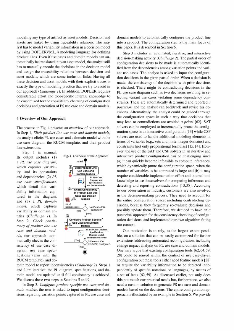
The process in Fig. 4 presents an overview of our approach.In Step 1, Elicit product line use case and domain models,the analyst elicits PL use cases and a domain model with theuse case diagram, the RUCM template, and their productline extensions.
Fig. 4 Overview of the Approach
Check Consistency of Product Line Use Case and Domain
Models
start
Elicit Product Line Use Case and
Domain Models
Are the models consistent?
Configure Product Specific Use Case and Domain
Models
[Yes][No]
PL Use CaseDiagram and
Specifications,and Domain Model
•• •• •• •• •• •• •• ••
List ofInconsistencies
1
PS Use Case Diagram, Specifications, Domain Model,
and Decision Model
Is there another product to configure?
[Yes]
[No]
2
3
Step 1 is manual.Its output includes (1)a PL use case diagram,which captures variabil-ity, and its constraintsand dependencies, (2) PLuse case specifications,which detail the vari-ability information cap-tured in the diagram,and (3) a PL domainmodel, which capturesvariability in domain en-tities (Challenge 1). InStep 2, Check consis-tency of product line usecase and domain mod-els, our approach auto-matically checks the con-sistency of use case di-agram, use case speci-fications (also with theRUCM template), and do-main model to report inconsistencies (Challenge 2). Steps 1and 2 are iterative: the PL diagram, specifications, and do-main model are updated until full consistency is achieved.We discuss these two steps in Sections 5 and 9.
In Step 3, Configure product specific use case and do-main models, the user is asked to input configuration deci-sions regarding variation points captured in PL use case and
domain models to automatically configure the product lineinto a product. The configuration step is the main focus ofthis paper. It is described in Section 6.
Step 3 includes an automated, iterative, and interactivedecision-making activity (Challenge 2). The partial order ofconfiguration decisions to be made is automatically identi-fied from the dependencies among variation points and vari-ant use cases. The analyst is asked to input the configura-tion decisions in the given partial order. When a decision ismade, the consistency of the decision with prior decisionsis checked. There might be contradicting decisions in thePL use case diagram such as two decisions resulting in se-lecting variant use cases violating some dependency con-straints. These are automatically determined and reported aposteriori and the analyst can backtrack and revise his de-cisions. Alternatively, the analyst could be guided throughthe configuration space in such a way that decisions thatmay lead to contradictions are avoided a priori [62]. SATsolvers can be employed to incrementally prune the config-uration space in an interactive configuration [13] while CSPsolvers are used to handle additional modeling elements interms of variables (e.g., sets and finite integer domains) andconstraints (not only propositional formulas) [15,14]. How-ever, the use of the SAT and CSP solvers in an iterative andinteractive product configuration can be challenging since(a) it can quickly become infeasible to compute inferences,which dynamically prune the configuration space, when thenumber of variables to be computed is large and (b) it mayrequire considerable implementation effort and internal toolknowledge to use these solvers for computing inferences anddetecting and reporting contradictions [13,38]. Accordingto our observation in industry, customers are also involvedin the decision-making process. They need to account forthe entire configuration space, including contradicting de-cisions, because they frequently re-evaluate decisions andpossibly update them. Therefore, we decided to have an aposteriori approach for the consistency checking of configu-ration decisions, and implemented our own algorithm fittingour context.
Our motivation is to rely, to the largest extent possi-ble, on a solution that can be easily customized for furtherextensions addressing automated reconfiguration, includingchange impact analysis on PL use case and domain models.One may argue that existing configuration tools [62,64,59,28] could be reused within the context of use case-drivenconfiguration but these tools either need feature models [28]or require the variability information to be depicted inde-pendently of specific notations or languages, by means ofa set of facts [62,59]. As discussed earlier, not only doesthis not match our practical needs but, furthermore, we alsoneed a custom solution to generate PS use case and domainmodels based on the decisions. The entire configuration ap-proach is illustrated by an example in Section 6. We provide
the details of our decision consistency checking algorithmin Section 7, whereas Section 8 presents the generation ofPS use case and domain models from PL models.
5 Elicitation of Variability in Use cases
Our configuration approach starts with the activity of elic-itation of PL use case and domain models. This activity isbased on the Product line Use case modeling Method (PUM)which we present in our previous paper [44]. The artifacts ofPUM is a PL use case diagram using product line extensionsproposed by Halmans and Pohl [45,23], PL use case speci-fications using RUCM extensions which we propose, and aPL domain model using stereotypes provided by Ziadi andJezequel [82]. In this section, we give a brief description ofthese PL artifacts.
5.1 Use Case Diagram with Product Line Extensions
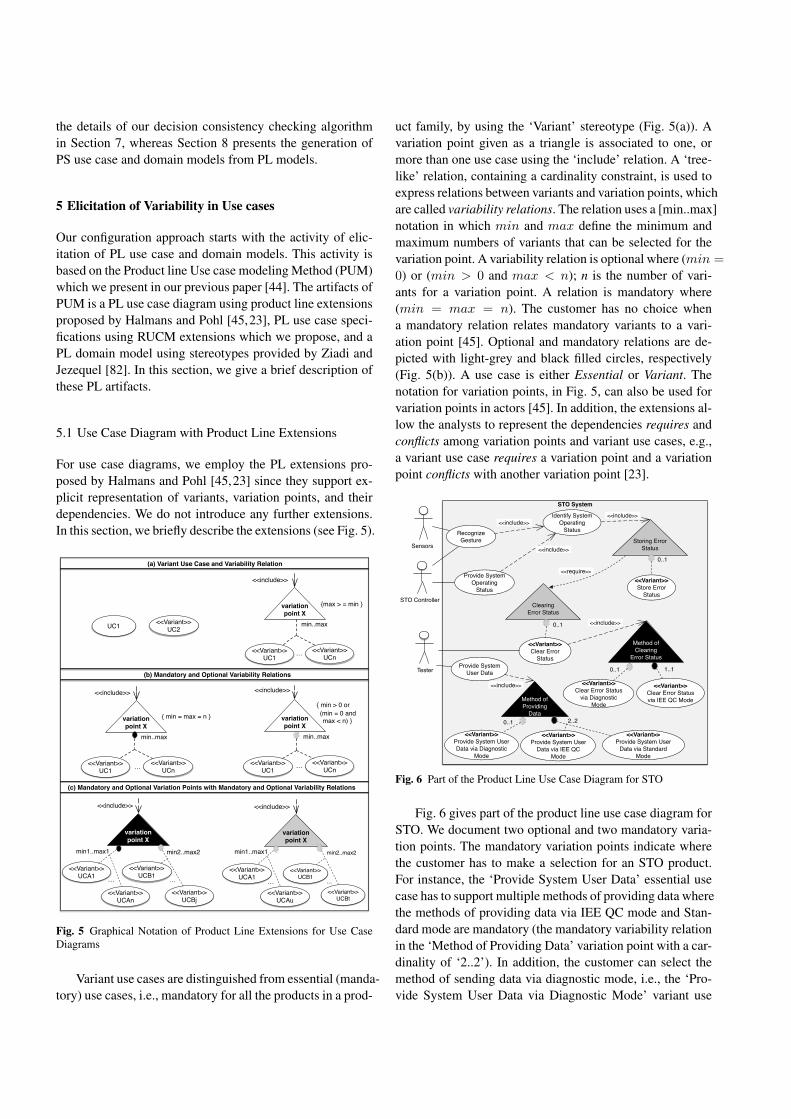
For use case diagrams, we employ the PL extensions pro-posed by Halmans and Pohl [45,23] since they support ex-plicit representation of variants, variation points, and theirdependencies. We do not introduce any further extensions.In this section, we briefly describe the extensions (see Fig. 5).
variation point X
<<Variant>>UC1
<<include>>
min..max
<<Variant>>UCn
variation point X
<<Variant>>UC1
<<include>>
min..max
<<Variant>>UCn… …
variation point X
<<Variant>>UCA1
<<include>>
min1..max1
<<Variant>>UCAn
…<<Variant>>
UCB1
min2..max2
<<Variant>>UCBj
…
variation point X
<<Variant>>UCA1
<<include>>
min1..max1
<<Variant>>UCAu
…
<<Variant>>UCB1
min2..max2
<<Variant>>UCBt
…
variation point X
<<Variant>>UC1
<<include>>
min..max
<<Variant>>UCn…
UC1 <<Variant>>UC2
(a) Variant Use Case and Variability Relation
(b) Mandatory and Optional Variability Relations
(c) Mandatory and Optional Variation Points with Mandatory and Optional Variability Relations
{max > = min }
{ min = max = n }
{ min > 0 or (min = 0 and max < n) }
Fig. 5 Graphical Notation of Product Line Extensions for Use CaseDiagrams
Variant use cases are distinguished from essential (manda-tory) use cases, i.e., mandatory for all the products in a prod-
uct family, by using the ‘Variant’ stereotype (Fig. 5(a)). Avariation point given as a triangle is associated to one, ormore than one use case using the ‘include’ relation. A ‘tree-like’ relation, containing a cardinality constraint, is used toexpress relations between variants and variation points, whichare called variability relations. The relation uses a [min..max]notation in which min and max define the minimum andmaximum numbers of variants that can be selected for thevariation point. A variability relation is optional where (min =
0) or (min > 0 and max < n); n is the number of vari-ants for a variation point. A relation is mandatory where(min = max = n). The customer has no choice whena mandatory relation relates mandatory variants to a vari-ation point [45]. Optional and mandatory relations are de-picted with light-grey and black filled circles, respectively(Fig. 5(b)). A use case is either Essential or Variant. Thenotation for variation points, in Fig. 5, can also be used forvariation points in actors [45]. In addition, the extensions al-low the analysts to represent the dependencies requires andconflicts among variation points and variant use cases, e.g.,a variant use case requires a variation point and a variationpoint conflicts with another variation point [23].
STO System
Sensors
Recognize Gesture
Identify System Operating
Status
Storing Error Status
Provide System Operating
Status
TesterProvide System
User Data
<<include>>
<<Variant>>Store Error
Status
<<include>>
Clearing Error Status
<<Variant>>Clear Error
Status
Method of Providing
Data
<<Variant>>Provide System User Data via Diagnostic
Mode
<<Variant>>Provide System User
Data via Standard Mode
<<Variant>>Provide System User
Data via IEE QC Mode
<<include>>
0..1
2..20..1
0..1
<<Variant>>Clear Error Status
via Diagnostic Mode
<<Variant>>Clear Error Status via IEE QC Mode
0..1
<<include>>
Method of Clearing
Error Status
1..1
<<require>>
STO Controller
<<include>>
Fig. 6 Part of the Product Line Use Case Diagram for STO
Fig. 6 gives part of the product line use case diagram forSTO. We document two optional and two mandatory varia-tion points. The mandatory variation points indicate wherethe customer has to make a selection for an STO product.For instance, the ‘Provide System User Data’ essential usecase has to support multiple methods of providing data wherethe methods of providing data via IEE QC mode and Stan-dard mode are mandatory (the mandatory variability relationin the ‘Method of Providing Data’ variation point with a car-dinality of ‘2..2’). In addition, the customer can select themethod of sending data via diagnostic mode, i.e., the ‘Pro-vide System User Data via Diagnostic Mode’ variant use
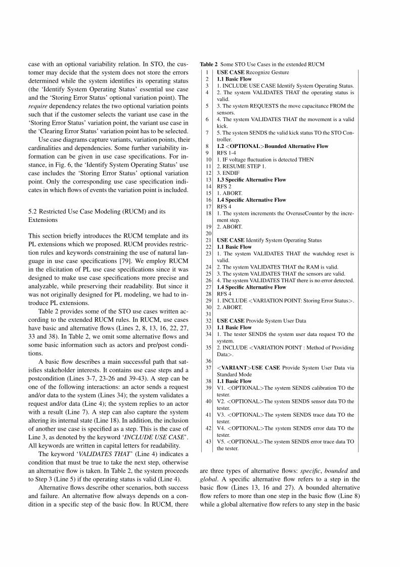
case with an optional variability relation. In STO, the cus-tomer may decide that the system does not store the errorsdetermined while the system identifies its operating status(the ‘Identify System Operating Status’ essential use caseand the ‘Storing Error Status’ optional variation point). Therequire dependency relates the two optional variation pointssuch that if the customer selects the variant use case in the‘Storing Error Status’ variation point, the variant use case inthe ‘Clearing Error Status’ variation point has to be selected.
Use case diagrams capture variants, variation points, theircardinalities and dependencies. Some further variability in-formation can be given in use case specifications. For in-stance, in Fig. 6, the ‘Identify System Operating Status’ usecase includes the ‘Storing Error Status’ optional variationpoint. Only the corresponding use case specification indi-cates in which flows of events the variation point is included.
5.2 Restricted Use Case Modeling (RUCM) and itsExtensions
This section briefly introduces the RUCM template and itsPL extensions which we proposed. RUCM provides restric-tion rules and keywords constraining the use of natural lan-guage in use case specifications [79]. We employ RUCMin the elicitation of PL use case specifications since it wasdesigned to make use case specifications more precise andanalyzable, while preserving their readability. But since itwas not originally designed for PL modeling, we had to in-troduce PL extensions.
Table 2 provides some of the STO use cases written ac-cording to the extended RUCM rules. In RUCM, use caseshave basic and alternative flows (Lines 2, 8, 13, 16, 22, 27,33 and 38). In Table 2, we omit some alternative flows andsome basic information such as actors and pre/post condi-tions.
A basic flow describes a main successful path that sat-isfies stakeholder interests. It contains use case steps and apostcondition (Lines 3-7, 23-26 and 39-43). A step can beone of the following interactions: an actor sends a requestand/or data to the system (Lines 34); the system validates arequest and/or data (Line 4); the system replies to an actorwith a result (Line 7). A step can also capture the systemaltering its internal state (Line 18). In addition, the inclusionof another use case is specified as a step. This is the case ofLine 3, as denoted by the keyword ‘INCLUDE USE CASE’.All keywords are written in capital letters for readability.
The keyword ‘VALIDATES THAT’ (Line 4) indicates acondition that must be true to take the next step, otherwisean alternative flow is taken. In Table 2, the system proceedsto Step 3 (Line 5) if the operating status is valid (Line 4).
Alternative flows describe other scenarios, both successand failure. An alternative flow always depends on a con-dition in a specific step of the basic flow. In RUCM, there
Table 2 Some STO Use Cases in the extended RUCM1 USE CASE Recognize Gesture2 1.1 Basic Flow3 1. INCLUDE USE CASE Identify System Operating Status.4 2. The system VALIDATES THAT the operating status is
valid.5 3. The system REQUESTS the move capacitance FROM the
sensors.6 4. The system VALIDATES THAT the movement is a valid
kick.7 5. The system SENDS the valid kick status TO the STO Con-
troller.8 1.2 <OPTIONAL>Bounded Alternative Flow9 RFS 1-410 1. IF voltage fluctuation is detected THEN11 2. RESUME STEP 1.12 3. ENDIF13 1.3 Specific Alternative Flow14 RFS 215 1. ABORT.16 1.4 Specific Alternative Flow17 RFS 418 1. The system increments the OveruseCounter by the incre-
ment step.19 2. ABORT.2021 USE CASE Identify System Operating Status22 1.1 Basic Flow23 1. The system VALIDATES THAT the watchdog reset is
valid.24 2. The system VALIDATES THAT the RAM is valid.25 3. The system VALIDATES THAT the sensors are valid.26 4. The system VALIDATES THAT there is no error detected.27 1.4 Specific Alternative Flow28 RFS 429 1. INCLUDE <VARIATION POINT: Storing Error Status>.30 2. ABORT.3132 USE CASE Provide System User Data33 1.1 Basic Flow34 1. The tester SENDS the system user data request TO the
system.35 2. INCLUDE <VARIATION POINT : Method of Providing
Data>.3637 <VARIANT>USE CASE Provide System User Data via
Standard Mode38 1.1 Basic Flow39 V1. <OPTIONAL>The system SENDS calibration TO the
tester.40 V2. <OPTIONAL>The system SENDS sensor data TO the
tester.41 V3. <OPTIONAL>The system SENDS trace data TO the
tester.42 V4. <OPTIONAL>The system SENDS error data TO the
tester.43 V5. <OPTIONAL>The system SENDS error trace data TO
the tester.
are three types of alternative flows: specific, bounded andglobal. A specific alternative flow refers to a step in thebasic flow (Lines 13, 16 and 27). A bounded alternativeflow refers to more than one step in the basic flow (Line 8)while a global alternative flow refers to any step in the basic
flow. For specific and bounded alternative flows, the key-word ‘RFS’ is used to refer to one or more reference flowsteps (Lines 9, 14, 17, and 28).
Bounded and global alternative flows begin with ‘IF ..THEN’ for the condition under which the alternative flow istaken (Line 10). Specific alternative flows do not necessarilybegin with ‘IF .. THEN’ since a guard condition is alreadyindicated in its reference flow step (Line 4).
Our RUCM extensions are twofold: (i) new keywordsand restriction rules for modeling interactions in embeddedsystems and restricting the use of existing keywords; (ii)new keywords for modeling variability in use case speci-fications.
We introduce extensions into RUCM regarding the us-age of ‘IF’ conditions and the way input/output messagesare expressed. PUM follows the guidelines that suggest notto use multiple branches within the same use case path [48],thus enforcing the usage of ‘IF’ conditions only as a meansto specify guard conditions for alternative flows. PUM in-troduces the keywords ‘SENDS .. TO’ and ‘REQUESTS ..FROM’ to distinguish system-actor interactions. Accordingto our experience, in embedded systems, system-actor inter-actions are always specified in terms of messages. For in-stance, Step 3 in Table 2 (Line 5) indicates an input messagefrom the sensors to the system while Step 5 (Line 7) containsan output message from the system to the STO Controller.Additional keywords can be defined for other types of sys-tems.
To reflect variability in use case specifications in a re-stricted form, we introduce into the RUCM template the no-tion of variation point and variant, complementary to thediagram extensions in Section 5.1. Variation points can beincluded in basic or alternative flows of use cases. We em-ploy the ‘INCLUDE <VARIATION POINT : ... >’ keywordto specify the inclusion of variation points in use case speci-fications (Lines 29 and 35). Variant use cases are given withthe ‘<VARIANT >’ keyword (Line 37). The same keywordis also used for variant actors related to a variation pointgiven in the use case diagram.
There are types of variability (e.g, optional steps and op-tional alternative flows) which cannot be captured in usecase diagrams due to the required level of granularity forproduct configuration. To model such variability, as part ofthe RUCM template extensions, we introduce optional steps,optional alternative flows and a variant order of steps. Op-tional steps and optional alternative flows begin with the‘<OPTIONAL>’ keyword (Lines 8 and 39-43). In addition,the order of use case steps may also vary. We use the ‘V’keyword before the step number to express the variant steporder (Lines 39-43). A variant order occurs with optionaland/or mandatory steps. It is important because variabilityin the system behavior can be introduced by multiple execu-tion orders of the same steps. For instance, the steps of the
basic flow of the ‘Provide System User Data via StandardMode’ use case are optional. Based on the testing procedurefollowed in the STO product, the order of sending data to thetester also varies. In the product configuration, the customerhas to decide which optional step to include in which orderin the use case specification.
5.3 Product Line Domain Model
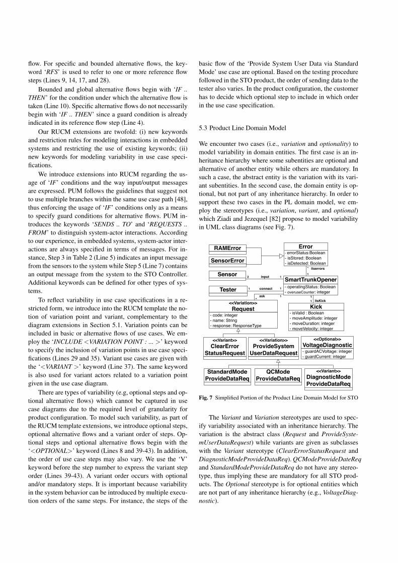
We encounter two cases (i.e., variation and optionality) tomodel variability in domain entities. The first case is an in-heritance hierarchy where some subentities are optional andalternative of another entity while others are mandatory. Insuch a case, the abstract entity is the variation with its vari-ant subentities. In the second case, the domain entity is op-tional, but not part of any inheritance hierarchy. In order tosupport these two cases in the PL domain model, we em-ploy the stereotypes (i.e., variation, variant, and optional)which Ziadi and Jezequel [82] propose to model variabilityin UML class diagrams (see Fig. 7).
<<Variation>>Request
- code: integer- name: String- response: ResponseType
Sensor
Tester1
<<Variant>>ClearError
StatusRequest
Error- errorStatus:Boolean- isStored: Boolean- isDetected: Boolean
itserrors*
SmartTrunkOpener- operatingStatus: Boolean- overuseCounter: integer
1
<<Variation>>ProvideSystem
UserDataRequest
Kick- isValid : Boolean- moveAmplitude: integer- moveDuration: integer- moveVelocity: integer
1
input
connect
itsKick
12
1 1
1*
ask
SensorError
RAMError
StandardModeProvideDataReq
QCModeProvideDataReq
<<Variant>>DiagnosticModeProvideDataReq
<<Optional>>VoltageDiagnostic- guardACVoltage: integer- guardCurrent: integer
Fig. 7 Simplified Portion of the Product Line Domain Model for STO
The Variant and Variation stereotypes are used to spec-ify variability associated with an inheritance hierarchy. Thevariation is the abstract class (Request and ProvideSyste-mUserDataRequest) while variants are given as subclasseswith the Variant stereotype (ClearErrorStatusRequest andDiagnosticModeProvideDataReq). QCModeProvideDateReqand StandardModeProvideDataReq do not have any stereo-type, thus implying these are mandatory for all STO prod-ucts. The Optional stereotype is for optional entities whichare not part of any inheritance hierarchy (e.g., VoltageDiag-nostic).
- name: StringVariationPoint
DecisionModel
- isSelected: Boolean
OptionalVariation Point
MandatoryVariation Point
- name: StringUseCase
- isSelected: Boolean
VariantUseCase
EssentialUseCase
- orderNumber: Integer- variantOrderNumber: Integer
Step
- isSelected: BooleanOptionalStep Mandatory
Step
1..*variants
1 variationpoint
1 ..*
0..*
0..*
- isSelected: Boolean
OptionalAlternativeFlow
MandatoryAlternativeFlow
BasicFlow
- name: StringVariantOrder
1
0..* 1
2..*
Flow - number: Integer
0..*- name: String- isSelected: Boolean
VariantActor0..*
variationpoint
0..*
usecases
- name: String-isSelected: Boolean
DomainEntity 0..*
1
0..1
1
1 1
1
0..*
Fig. 8 Decision Metamodel
The PL domain model in Fig. 7 does not contain anyvariant dependency such that the selection of one variantdomain entity disables (or enables) the selection of someother variant entities. Ziadi and Jezequel [82] propose tospecify such dependencies in the Object Constraint Lan-guage (OCL). Alternatively, some special stereotypes, e.g.,requires and conflicts, can also be employed for UML classassociations to specify the variant dependencies in PL do-main models.
6 Configuration of Product Specific Use Case andDomain Models
The product configuration is a decision-making process, wherethe variability information is examined to select the desiredfeatures for the product. A product in a product family isdefined as a unique combination of features selected duringconfiguration. In this paper, we rely on variability informa-tion given in the PL use case diagram, specifications anddomain model. The user selects (1) the desired use cases inthe PL use case diagram, (2) use case elements in the PL usecase specifications, and (3) domain entities in the PL domainmodel, to generate the PS use case diagram, specifications,and domain model.
Our configuration mechanism relies on a use case con-figuration function. The configuration function takes a PLuse case diagram, a set of PL use case specifications, anda PL domain model as input, and produces a PS use casediagram, a set of PS use case specifications, a PS domainmodel, and a decision model which captures configurationdecisions. Such a decision model is important since the an-alyst/customer may need to update decisions to reconfigurethe PS models for the same product.
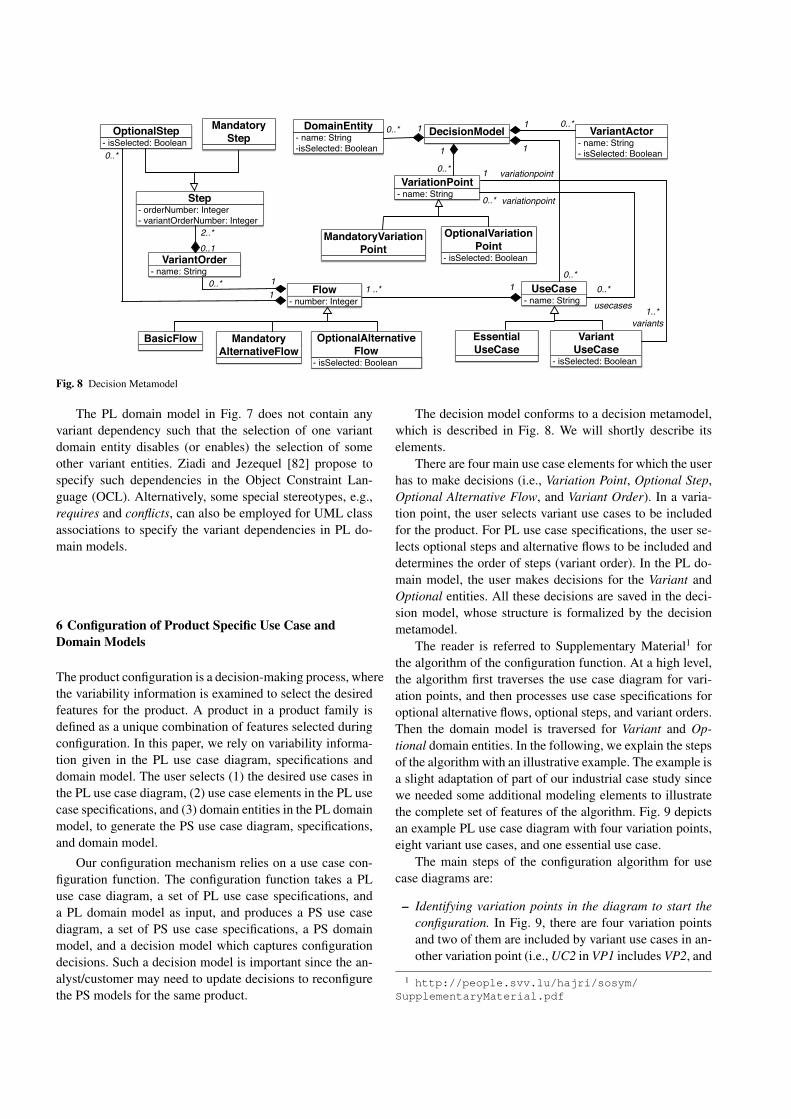
The decision model conforms to a decision metamodel,which is described in Fig. 8. We will shortly describe itselements.
There are four main use case elements for which the userhas to make decisions (i.e., Variation Point, Optional Step,Optional Alternative Flow, and Variant Order). In a varia-tion point, the user selects variant use cases to be includedfor the product. For PL use case specifications, the user se-lects optional steps and alternative flows to be included anddetermines the order of steps (variant order). In the PL do-main model, the user makes decisions for the Variant andOptional entities. All these decisions are saved in the deci-sion model, whose structure is formalized by the decisionmetamodel.
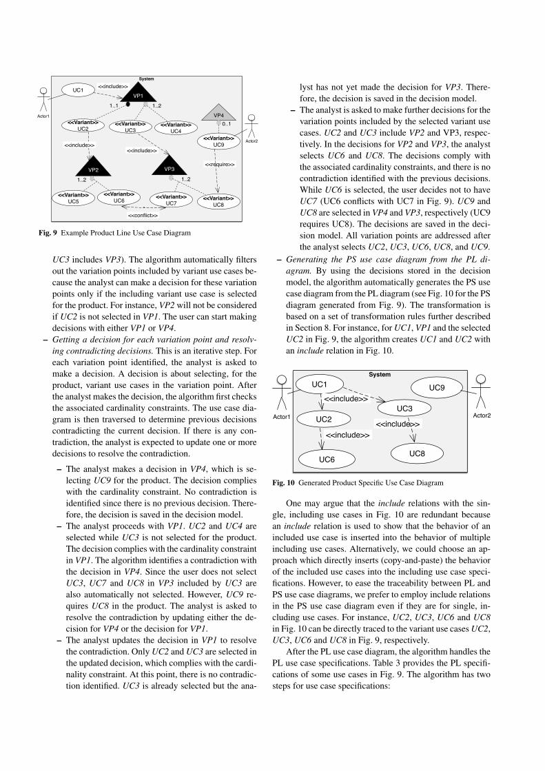
The reader is referred to Supplementary Material1 forthe algorithm of the configuration function. At a high level,the algorithm first traverses the use case diagram for vari-ation points, and then processes use case specifications foroptional alternative flows, optional steps, and variant orders.Then the domain model is traversed for Variant and Op-tional domain entities. In the following, we explain the stepsof the algorithm with an illustrative example. The example isa slight adaptation of part of our industrial case study sincewe needed some additional modeling elements to illustratethe complete set of features of the algorithm. Fig. 9 depictsan example PL use case diagram with four variation points,eight variant use cases, and one essential use case.
The main steps of the configuration algorithm for usecase diagrams are:
– Identifying variation points in the diagram to start theconfiguration. In Fig. 9, there are four variation pointsand two of them are included by variant use cases in an-other variation point (i.e., UC2 in VP1 includes VP2, and
1 http://people.svv.lu/hajri/sosym/SupplementaryMaterial.pdf
System
Actor1
UC1
VP4
<<Variant>>UC9
<<include>>
VP2
<<Variant>>UC6
<<Variant>>UC5
0..1
1..2
<<Variant>>UC2
<<Variant>>UC3
1..1
VP1
1..2
Actor2
<<Variant>>UC4
VP3
<<Variant>>UC8
<<Variant>>UC7
1..2
<<include>><<include>>
<<conflict>>
<<require>>
Fig. 9 Example Product Line Use Case Diagram
UC3 includes VP3). The algorithm automatically filtersout the variation points included by variant use cases be-cause the analyst can make a decision for these variationpoints only if the including variant use case is selectedfor the product. For instance, VP2 will not be consideredif UC2 is not selected in VP1. The user can start makingdecisions with either VP1 or VP4.
– Getting a decision for each variation point and resolv-ing contradicting decisions. This is an iterative step. Foreach variation point identified, the analyst is asked tomake a decision. A decision is about selecting, for theproduct, variant use cases in the variation point. Afterthe analyst makes the decision, the algorithm first checksthe associated cardinality constraints. The use case dia-gram is then traversed to determine previous decisionscontradicting the current decision. If there is any con-tradiction, the analyst is expected to update one or moredecisions to resolve the contradiction.
– The analyst makes a decision in VP4, which is se-lecting UC9 for the product. The decision complieswith the cardinality constraint. No contradiction isidentified since there is no previous decision. There-fore, the decision is saved in the decision model.
– The analyst proceeds with VP1. UC2 and UC4 areselected while UC3 is not selected for the product.The decision complies with the cardinality constraintin VP1. The algorithm identifies a contradiction withthe decision in VP4. Since the user does not selectUC3, UC7 and UC8 in VP3 included by UC3 arealso automatically not selected. However, UC9 re-quires UC8 in the product. The analyst is asked toresolve the contradiction by updating either the de-cision for VP4 or the decision for VP1.
– The analyst updates the decision in VP1 to resolvethe contradiction. Only UC2 and UC3 are selected inthe updated decision, which complies with the cardi-nality constraint. At this point, there is no contradic-tion identified. UC3 is already selected but the ana-
lyst has not yet made the decision for VP3. There-fore, the decision is saved in the decision model.
– The analyst is asked to make further decisions for thevariation points included by the selected variant usecases. UC2 and UC3 include VP2 and VP3, respec-tively. In the decisions for VP2 and VP3, the analystselects UC6 and UC8. The decisions comply withthe associated cardinality constraints, and there is nocontradiction identified with the previous decisions.While UC6 is selected, the user decides not to haveUC7 (UC6 conflicts with UC7 in Fig. 9). UC9 andUC8 are selected in VP4 and VP3, respectively (UC9requires UC8). The decisions are saved in the deci-sion model. All variation points are addressed afterthe analyst selects UC2, UC3, UC6, UC8, and UC9.
– Generating the PS use case diagram from the PL di-agram. By using the decisions stored in the decisionmodel, the algorithm automatically generates the PS usecase diagram from the PL diagram (see Fig. 10 for the PSdiagram generated from Fig. 9). The transformation isbased on a set of transformation rules further describedin Section 8. For instance, for UC1, VP1 and the selectedUC2 in Fig. 9, the algorithm creates UC1 and UC2 withan include relation in Fig. 10.
System
Actor1
UC1 UC9<<include>>
UC6
UC2 Actor2UC3
UC8
<<include>><<include>>
Fig. 10 Generated Product Specific Use Case Diagram
One may argue that the include relations with the sin-gle, including use cases in Fig. 10 are redundant becausean include relation is used to show that the behavior of anincluded use case is inserted into the behavior of multipleincluding use cases. Alternatively, we could choose an ap-proach which directly inserts (copy-and-paste) the behaviorof the included use cases into the including use case speci-fications. However, to ease the traceability between PL andPS use case diagrams, we prefer to employ include relationsin the PS use case diagram even if they are for single, in-cluding use cases. For instance, UC2, UC3, UC6 and UC8in Fig. 10 can be directly traced to the variant use cases UC2,UC3, UC6 and UC8 in Fig. 9, respectively.
After the PL use case diagram, the algorithm handles thePL use case specifications. Table 3 provides the PL specifi-cations of some use cases in Fig. 9. The algorithm has twosteps for use case specifications:
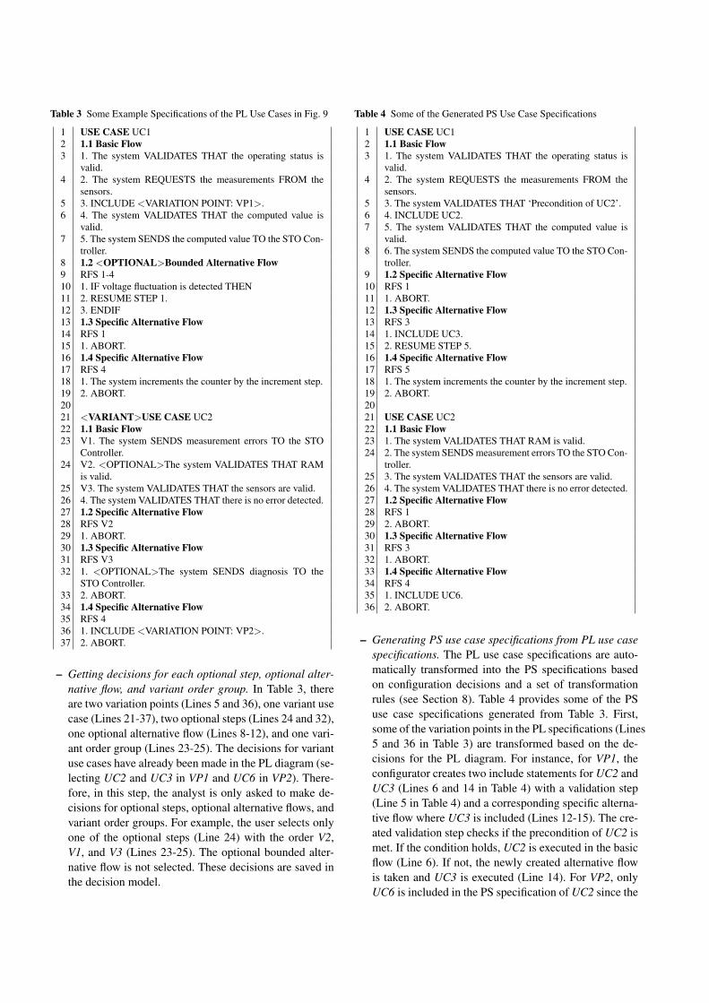
Table 3 Some Example Specifications of the PL Use Cases in Fig. 9
1 USE CASE UC12 1.1 Basic Flow3 1. The system VALIDATES THAT the operating status is
valid.4 2. The system REQUESTS the measurements FROM the
sensors.5 3. INCLUDE <VARIATION POINT: VP1>.6 4. The system VALIDATES THAT the computed value is
valid.7 5. The system SENDS the computed value TO the STO Con-
troller.8 1.2 <OPTIONAL>Bounded Alternative Flow9 RFS 1-410 1. IF voltage fluctuation is detected THEN11 2. RESUME STEP 1.12 3. ENDIF13 1.3 Specific Alternative Flow14 RFS 115 1. ABORT.16 1.4 Specific Alternative Flow17 RFS 418 1. The system increments the counter by the increment step.19 2. ABORT.2021 <VARIANT>USE CASE UC222 1.1 Basic Flow23 V1. The system SENDS measurement errors TO the STO
Controller.24 V2. <OPTIONAL>The system VALIDATES THAT RAM
is valid.25 V3. The system VALIDATES THAT the sensors are valid.26 4. The system VALIDATES THAT there is no error detected.27 1.2 Specific Alternative Flow28 RFS V229 1. ABORT.30 1.3 Specific Alternative Flow31 RFS V332 1. <OPTIONAL>The system SENDS diagnosis TO the
STO Controller.33 2. ABORT.34 1.4 Specific Alternative Flow35 RFS 436 1. INCLUDE <VARIATION POINT: VP2>.37 2. ABORT.
– Getting decisions for each optional step, optional alter-native flow, and variant order group. In Table 3, thereare two variation points (Lines 5 and 36), one variant usecase (Lines 21-37), two optional steps (Lines 24 and 32),one optional alternative flow (Lines 8-12), and one vari-ant order group (Lines 23-25). The decisions for variantuse cases have already been made in the PL diagram (se-lecting UC2 and UC3 in VP1 and UC6 in VP2). There-fore, in this step, the analyst is only asked to make de-cisions for optional steps, optional alternative flows, andvariant order groups. For example, the user selects onlyone of the optional steps (Line 24) with the order V2,V1, and V3 (Lines 23-25). The optional bounded alter-native flow is not selected. These decisions are saved inthe decision model.
Table 4 Some of the Generated PS Use Case Specifications
1 USE CASE UC12 1.1 Basic Flow3 1. The system VALIDATES THAT the operating status is
valid.4 2. The system REQUESTS the measurements FROM the
sensors.5 3. The system VALIDATES THAT ‘Precondition of UC2’.6 4. INCLUDE UC2.7 5. The system VALIDATES THAT the computed value is
valid.8 6. The system SENDS the computed value TO the STO Con-
troller.9 1.2 Specific Alternative Flow10 RFS 111 1. ABORT.12 1.3 Specific Alternative Flow13 RFS 314 1. INCLUDE UC3.15 2. RESUME STEP 5.16 1.4 Specific Alternative Flow17 RFS 518 1. The system increments the counter by the increment step.19 2. ABORT.2021 USE CASE UC222 1.1 Basic Flow23 1. The system VALIDATES THAT RAM is valid.24 2. The system SENDS measurement errors TO the STO Con-
troller.25 3. The system VALIDATES THAT the sensors are valid.26 4. The system VALIDATES THAT there is no error detected.27 1.2 Specific Alternative Flow28 RFS 129 2. ABORT.30 1.3 Specific Alternative Flow31 RFS 332 1. ABORT.33 1.4 Specific Alternative Flow34 RFS 435 1. INCLUDE UC6.36 2. ABORT.
– Generating PS use case specifications from PL use casespecifications. The PL use case specifications are auto-matically transformed into the PS specifications basedon configuration decisions and a set of transformationrules (see Section 8). Table 4 provides some of the PSuse case specifications generated from Table 3. First,some of the variation points in the PL specifications (Lines5 and 36 in Table 3) are transformed based on the de-cisions for the PL diagram. For instance, for VP1, theconfigurator creates two include statements for UC2 andUC3 (Lines 6 and 14 in Table 4) with a validation step(Line 5 in Table 4) and a corresponding specific alterna-tive flow where UC3 is included (Lines 12-15). The cre-ated validation step checks if the precondition of UC2 ismet. If the condition holds, UC2 is executed in the basicflow (Line 6). If not, the newly created alternative flowis taken and UC3 is executed (Line 14). For VP2, onlyUC6 is included in the PS specification of UC2 since the
user selects only UC6. After handling variation points,selected optional steps and optional alternative flows areincluded in the PS specifications (Line 23). Variant ordergroups are ordered in the PS specifications according tothe given decision (Lines 23-26).
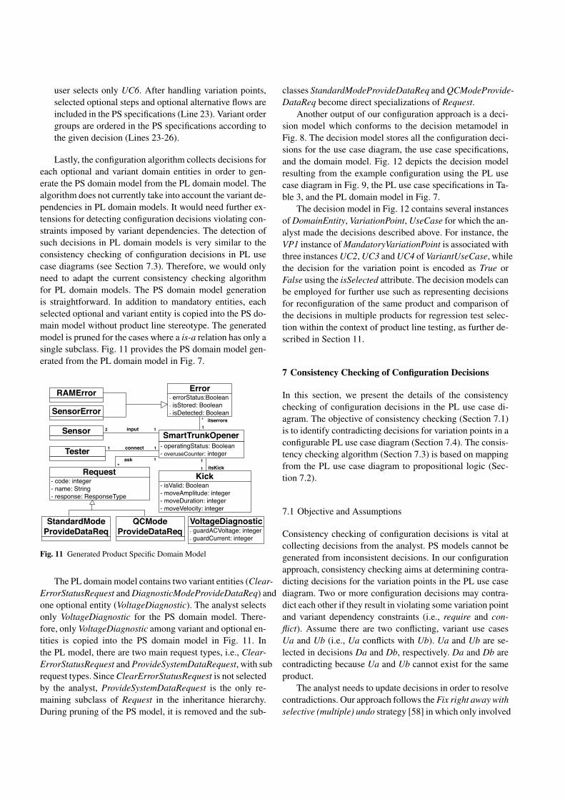
Lastly, the configuration algorithm collects decisions foreach optional and variant domain entities in order to gen-erate the PS domain model from the PL domain model. Thealgorithm does not currently take into account the variant de-pendencies in PL domain models. It would need further ex-tensions for detecting configuration decisions violating con-straints imposed by variant dependencies. The detection ofsuch decisions in PL domain models is very similar to theconsistency checking of configuration decisions in PL usecase diagrams (see Section 7.3). Therefore, we would onlyneed to adapt the current consistency checking algorithmfor PL domain models. The PS domain model generationis straightforward. In addition to mandatory entities, eachselected optional and variant entity is copied into the PS do-main model without product line stereotype. The generatedmodel is pruned for the cases where a is-a relation has only asingle subclass. Fig. 11 provides the PS domain model gen-erated from the PL domain model in Fig. 7.
Request- code: integer- name: String- response: ResponseType
Sensor
Tester
1
Error- errorStatus:Boolean- isStored: Boolean- isDetected: Boolean
itserrors*
SmartTrunkOpener- operatingStatus: Boolean- overuseCounter: integer
1
Kick- isValid: Boolean- moveAmplitude: integer- moveDuration: integer- moveVelocity: integer
1
input
connect
itsKick
12
1 1
1*ask
SensorError
RAMError
StandardModeProvideDataReq
QCModeProvideDataReq
VoltageDiagnostic- guardACVoltage: integer- guardCurrent: integer
Fig. 11 Generated Product Specific Domain Model
The PL domain model contains two variant entities (Clear-ErrorStatusRequest and DiagnosticModeProvideDataReq) andone optional entity (VoltageDiagnostic). The analyst selectsonly VoltageDiagnostic for the PS domain model. There-fore, only VoltageDiagnostic among variant and optional en-tities is copied into the PS domain model in Fig. 11. Inthe PL model, there are two main request types, i.e., Clear-ErrorStatusRequest and ProvideSystemDataRequest, with subrequest types. Since ClearErrorStatusRequest is not selectedby the analyst, ProvideSystemDataRequest is the only re-maining subclass of Request in the inheritance hierarchy.During pruning of the PS model, it is removed and the sub-
classes StandardModeProvideDataReq and QCModeProvide-DataReq become direct specializations of Request.
Another output of our configuration approach is a deci-sion model which conforms to the decision metamodel inFig. 8. The decision model stores all the configuration deci-sions for the use case diagram, the use case specifications,and the domain model. Fig. 12 depicts the decision modelresulting from the example configuration using the PL usecase diagram in Fig. 9, the PL use case specifications in Ta-ble 3, and the PL domain model in Fig. 7.
The decision model in Fig. 12 contains several instancesof DomainEntity, VariationPoint, UseCase for which the an-alyst made the decisions described above. For instance, theVP1 instance of MandatoryVariationPoint is associated withthree instances UC2, UC3 and UC4 of VariantUseCase, whilethe decision for the variation point is encoded as True orFalse using the isSelected attribute. The decision models canbe employed for further use such as representing decisionsfor reconfiguration of the same product and comparison ofthe decisions in multiple products for regression test selec-tion within the context of product line testing, as further de-scribed in Section 11.
7 Consistency Checking of Configuration Decisions
In this section, we present the details of the consistencychecking of configuration decisions in the PL use case di-agram. The objective of consistency checking (Section 7.1)is to identify contradicting decisions for variation points in aconfigurable PL use case diagram (Section 7.4). The consis-tency checking algorithm (Section 7.3) is based on mappingfrom the PL use case diagram to propositional logic (Sec-tion 7.2).
7.1 Objective and Assumptions
Consistency checking of configuration decisions is vital atcollecting decisions from the analyst. PS models cannot begenerated from inconsistent decisions. In our configurationapproach, consistency checking aims at determining contra-dicting decisions for the variation points in the PL use casediagram. Two or more configuration decisions may contra-dict each other if they result in violating some variation pointand variant dependency constraints (i.e., require and con-flict). Assume there are two conflicting, variant use casesUa and Ub (i.e., Ua conflicts with Ub). Ua and Ub are se-lected in decisions Da and Db, respectively. Da and Db arecontradicting because Ua and Ub cannot exist for the sameproduct.
The analyst needs to update decisions in order to resolvecontradictions. Our approach follows the Fix right away withselective (multiple) undo strategy [58] in which only involved
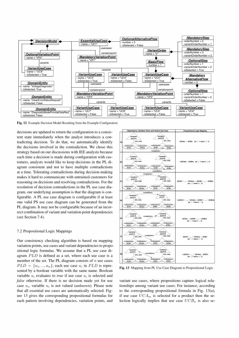
:DecisionModel- name = “UC1”:EssentialUseCase
- name = “VP1”:MandatoryVariationPoint- name = “VP4”
:OptionalVariationPoint
- name = “UC2”- isSelected = True
:VariantUseCase- name = “UC3”- isSelected = True
:VariantUseCase- name = “UC4”- isSelected = False
:VariantUseCase- name = “UC9”- isSelected = True
:VariantUseCase
- name = “VP2”:MandatoryVariationPoint
- name = “VP3”:MandatoryVariationPoint
- name = “UC5”- isSelected = False
:VariantUseCase- name = “UC6”- isSelected = True
:VariantUseCase- name = “UC7”- isSelected = False
:VariantUseCase- name = “UC8”- isSelected = True
:VariantUseCase
variants
variants
variationpoint
usecases usecases
variationpoint
variants variants
- name: “VoltageDiagnostic”- isSelected: True
:DomainEntity
- name: “ClearErrorStatusRequest”- isSelected: False
:DomainEntity
- name: “DiagnosticModeProvideDataReq”- isSelected: False
:DomainEntity
- number = 2- isSelected = False
:OptionalAlternativeFlow
- number = 1:BasicFlow
- name = “V”:VariantOrder
- orderNumber = 2- variantOrderNumber = 1
:MandatoryStep
- orderNumber = 3- variantOrderNumber = 3
:MandatoryStep
- orderNumber = 1- variantOrderNumber = 2- isSelected = True
:OptionalStep
- number = 3
:MandatoryAlternativeFlow
- orderNumber = 1- variantOrderNumber = 0- isSelected = False
:OptionalStep
usecases
variationpoint
Fig. 12 Example Decision Model Resulting from the Example Configuration
decisions are updated to return the configuration to a consis-tent state immediately when the analyst introduces a con-tradicting decision. To do that, we automatically identifythe decisions involved in the contradiction. We chose thisstrategy based on our discussions with IEE analysts becauseeach time a decision is made during configuration with cus-tomers, analysts would like to keep decisions in the PL di-agram consistent and not to have multiple contradictionsat a time. Tolerating contradictions during decision-makingmakes it hard to communicate with untrained customers forreasoning on decisions and resolving contradictions. For theresolution of decision contradictions in the PL use case dia-gram, our underlying assumption is that the diagram is con-figurable. A PL use case diagram is configurable if at leastone valid PS use case diagram can be generated from thePL diagram. It may not be configurable because of an incor-rect combination of variant and variation point dependencies(see Section 7.4).
7.2 Propositional Logic Mappings
Our consistency checking algorithm is based on mappingvariation points, use cases and variant dependencies to propo-sitional logic formulas. We assume that a PL use case di-agram PLD is defined as a set, where each use case is amember of the set. The PL diagram consists of n use casesPLD = {u1, ..., un}; each use case ui in PLD is repre-sented by a boolean variable with the same name. Booleanvariable ui evaluates to true if use case ui is selected andfalse otherwise. If there is no decision made yet for usecase ui, variable ui is not valued (unknown). Please notethat all essential use cases are automatically selected. Fig-ure 13 gives the corresponding propositional formulas foreach pattern involving dependencies, variation points, and
variation point A
<<Variant>>UCA1
min..max
<<Variant>>UCAm…
Dependency, Variation Point, and Variant Use Case Propositional Logic Mapping
variation point B
<<Variant>>UCB1
min..max
<<Variant>>UCBn…
<<require>>
UCAm ⟶ UCBn (m ��1 and n � 1)
¬ (UCAm ⋀ UCBn) (m ��1 and n � 1)
variation point A
<<Variant>>UCA1
min..max
<<Variant>>UCAm…
variation point B
<<Variant>>UCB1
min..max
<<Variant>>UCBn…
<<conflict>>
variation point A
<<Variant>>UCA1
min..max
<<Variant>>UCAm…
variation point B
<<Variant>>UCB1
min..max
<<Variant>>UCBn…
<<require>>
variation point A
<<Variant>>UCA1
min..max
<<Variant>>UCAm…
variation point B
<<Variant>>UCB1
min..max
<<Variant>>UCBn…
<<conflict>>
variation point A
<<Variant>>UCA1
min..max
<<Variant>>UCAm…
variation point B
<<Variant>>UCB1
min..max
<<Variant>>UCBn…
<<require>>
variation point A
<<Variant>>UCA1
min..max
<<Variant>>UCAm…
variation point B
<<Variant>>UCB1
min..max
<<Variant>>UCBn…
<<require>>
variation point A
<<Variant>>UCA1
min..max
<<Variant>>UCAm…
variation point B
<<Variant>>UCB1
min..max
<<Variant>>UCBn…
<<conflict>>
(UCA1 ⋁ … ⋁ UCAm) ⟶ (UCB1 ⋁ … ⋁ UCBn) (m ��1 and n � 1)
¬ ((UCA1 ⋁ … ⋁ UCAm) ⋀ (UCB1 ⋁ … ⋁ UCBn))(m ��1 and n � 1)
UCAm ⟶ (UCB1 ⋁ … ⋁ UCBn)(m ��1 and n � 1)
(UCA1 ⋁ … ⋁ UCAm) ⟶ UCB1(m ��1 and n � 1)
¬ ((UCA1 ⋁ … ⋁ UCAm) ⋀ UCB1)(m ��1 and n � 1)
(a)
(b)
(c)
(d)
(e)
(f)
(g)
Fig. 13 Mapping from PL Use Case Diagram to Propositional Logic
variant use cases, where propositions capture logical rela-tionships among variant use cases. For instance, accordingto the corresponding propositional formula in Fig. 13(a),if use case UCAm is selected for a product then the se-lection logically implies that use case UCBn is also se-
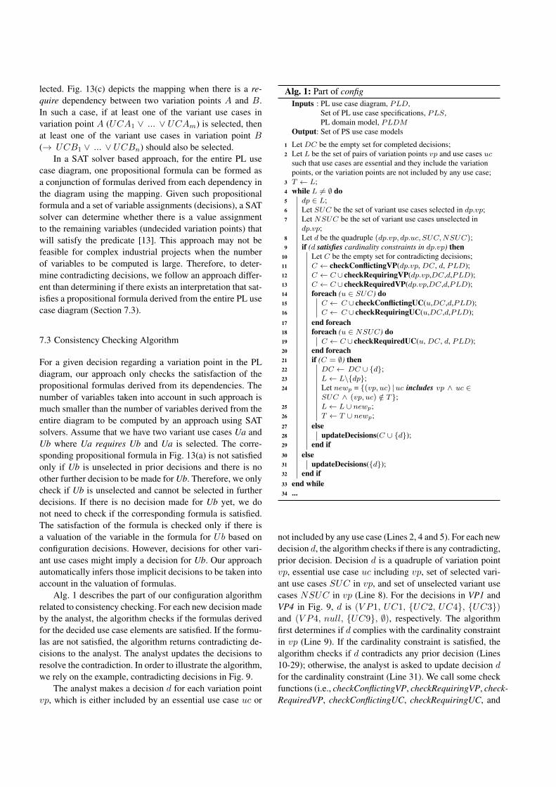
lected. Fig. 13(c) depicts the mapping when there is a re-quire dependency between two variation points A and B.In such a case, if at least one of the variant use cases invariation point A (UCA1 ∨ ... ∨ UCAm) is selected, thenat least one of the variant use cases in variation point B(→ UCB1 ∨ ... ∨ UCBn) should also be selected.
In a SAT solver based approach, for the entire PL usecase diagram, one propositional formula can be formed asa conjunction of formulas derived from each dependency inthe diagram using the mapping. Given such propositionalformula and a set of variable assignments (decisions), a SATsolver can determine whether there is a value assignmentto the remaining variables (undecided variation points) thatwill satisfy the predicate [13]. This approach may not befeasible for complex industrial projects when the numberof variables to be computed is large. Therefore, to deter-mine contradicting decisions, we follow an approach differ-ent than determining if there exists an interpretation that sat-isfies a propositional formula derived from the entire PL usecase diagram (Section 7.3).
7.3 Consistency Checking Algorithm
For a given decision regarding a variation point in the PLdiagram, our approach only checks the satisfaction of thepropositional formulas derived from its dependencies. Thenumber of variables taken into account in such approach ismuch smaller than the number of variables derived from theentire diagram to be computed by an approach using SATsolvers. Assume that we have two variant use cases Ua andUb where Ua requires Ub and Ua is selected. The corre-sponding propositional formula in Fig. 13(a) is not satisfiedonly if Ub is unselected in prior decisions and there is noother further decision to be made for Ub. Therefore, we onlycheck if Ub is unselected and cannot be selected in furtherdecisions. If there is no decision made for Ub yet, we donot need to check if the corresponding formula is satisfied.The satisfaction of the formula is checked only if there isa valuation of the variable in the formula for Ub based onconfiguration decisions. However, decisions for other vari-ant use cases might imply a decision for Ub. Our approachautomatically infers those implicit decisions to be taken intoaccount in the valuation of formulas.
Alg. 1 describes the part of our configuration algorithmrelated to consistency checking. For each new decision madeby the analyst, the algorithm checks if the formulas derivedfor the decided use case elements are satisfied. If the formu-las are not satisfied, the algorithm returns contradicting de-cisions to the analyst. The analyst updates the decisions toresolve the contradiction. In order to illustrate the algorithm,we rely on the example, contradicting decisions in Fig. 9.
The analyst makes a decision d for each variation pointvp, which is either included by an essential use case uc or
Alg. 1: Part of configInputs : PL use case diagram, PLD,
Set of PL use case specifications, PLS,PL domain model, PLDM
Output: Set of PS use case models
1 Let DC be the empty set for completed decisions;2 Let L be the set of pairs of variation points vp and use cases uc
such that use cases are essential and they include the variationpoints, or the variation points are not included by any use case;
3 T ← L;4 while L 6= ∅ do5 dp ∈ L;6 Let SUC be the set of variant use cases selected in dp.vp;7 Let NSUC be the set of variant use cases unselected in
dp.vp;8 Let d be the quadruple (dp.vp, dp.uc, SUC,NSUC);9 if (d satisfies cardinality constraints in dp.vp) then
10 Let C be the empty set for contradicting decisions;11 C ← checkConflictingVP(dp.vp, DC, d, PLD);12 C ← C ∪ checkRequiringVP(dp.vp,DC,d,PLD);13 C ← C ∪ checkRequiredVP(dp.vp,DC,d,PLD);14 foreach (u ∈ SUC) do15 C ← C ∪ checkConflictingUC(u,DC,d,PLD);16 C ← C ∪ checkRequiringUC(u,DC,d,PLD);17 end foreach18 foreach (u ∈ NSUC) do19 C ← C ∪ checkRequiredUC(u, DC, d, PLD);20 end foreach21 if (C = ∅) then22 DC ← DC ∪ {d};23 L← L\{dp};24 Let newp = {(vp, uc) |uc includes vp ∧ uc ∈
SUC ∧ (vp, uc) /∈ T};25 L← L ∪ newp;26 T ← T ∪ newp;27 else28 updateDecisions(C ∪ {d});29 end if30 else31 updateDecisions({d});32 end if33 end while34 ...
not included by any use case (Lines 2, 4 and 5). For each newdecision d, the algorithm checks if there is any contradicting,prior decision. Decision d is a quadruple of variation pointvp, essential use case uc including vp, set of selected vari-ant use cases SUC in vp, and set of unselected variant usecases NSUC in vp (Line 8). For the decisions in VP1 andVP4 in Fig. 9, d is (V P1, UC1, {UC2, UC4}, {UC3})and (V P4, null, {UC9}, ∅), respectively. The algorithmfirst determines if d complies with the cardinality constraintin vp (Line 9). If the cardinality constraint is satisfied, thealgorithm checks if d contradicts any prior decision (Lines10-29); otherwise, the analyst is asked to update decision d
for the cardinality constraint (Line 31). We call some checkfunctions (i.e., checkConflictingVP, checkRequiringVP, check-RequiredVP, checkConflictingUC, checkRequiringUC, and
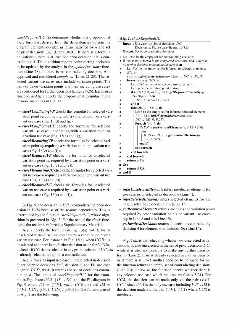
checkRequiredUC) to determine whether the propositionallogic formulas, derived from the dependencies to/from thediagram elements decided in d, are satisfied by d and setof prior decisions DC (Lines 10-20). If there is a formulanot satisfied, there is at least one prior decision that is con-tradicting d. The algorithm reports contradicting decisionsto be updated by the analyst in the updateDecisions func-tion (Line 28). If there is no contradicting decision, d isapproved and considered completed (Lines 21-23). The se-lected variant use cases may include variation points. Thepairs of those variation points and their including use casesare considered for further decisions (Lines 24-26). Each checkfunction in Alg. 1 checks the propositional formulas in oneor more mappings in Fig. 13.
– checkConflictingVP checks the formulas for selected vari-ation point vp conflicting with a variation point or a vari-ant use case (Fig. 13(d) and (g)),
– checkConflictingUC checks the formulas for selectedvariant use case u conflicting with a variation point ora variant use case (Fig. 13(b) and (g)),
– checkRequiringVP checks the formulas for selected vari-ation point vp requiring a variation point or a variant usecase (Fig. 13(c) and (f)),
– checkRequiredVP checks the formulas for unselectedvariation point vp required by a variation point or a vari-ant use case (Fig. 13(c) and (e)),
– checkRequiringUC checks the formulas for selected vari-ant use case u requiring a variation point or a variant usecase (Fig. 13(a) and (e)),
– checkRequiredUC checks the formulas for unselectedvariant use case u required by a variation point or a vari-ant use case (Fig. 13(a) and (f)).
In Fig. 9, the decision in V P1 contradicts the prior de-cision in V P4 because of the require dependency. This isdetermined by the function checkRequiredUC, whose algo-rithm is presented in Alg. 2. For the rest of the check func-tions, the reader is referred to Supplementary Material.
Alg. 2 checks the formulas in Fig. 13(a) and (f) for anunselected variant use case required by a variation point or avariant use case. For instance, in Fig. 13(a), when UCBn isunselected and there is no further decision made for UCBn,it checks if UCAm is selected in any prior decision. If UCAm
is already selected, it reports a contradiction.Alg. 2 takes as input use case uc unselected in decision
d, set of prior decisions DC, decision d, and PL use casediagram PLD, while it returns the set of decisions contra-dicting d. The inputs of checkRequiredUC for the exam-ple in Fig. 9 are UC3, {D1}, D2, and the PL diagram inFig. 9 where D1 = (V P4, null, {UC9}, ∅) and D2 =
(V P1, UC1, {UC2, UC4}, {UC3}). The functions usedin Alg. 2 are the following:
Alg. 2: checkRequiredUCInput : Use case, uc, Set of decisions, DC,
Decision, d, PL use case diagram, PLDOutput: Set of contradicting decisions
1 Let RES be the empty set for contradicting decisions;2 if ((uc is not selected in the completed decisions) and (there is
no further decision to be made for uc)) then3 Let EX be the empty set for inferred, unselected elements;4 EX ←
{uc} ∪ inferUnselectedElements(uc, d, DC, ∅, PLD);5 foreach (dm ∈ DC) do6 Let SUC be the set of selected use cases in dm;7 Let vp be the variation point in dm;8 if (SUC 6= ∅) and ((EX ∩ getRequiredElements(vp,
PLD)) 6= ∅) then9 RES ← RES ∪ {dm};
10 end if11 foreach (u ∈ SUC) do12 Let I be the empty set for inferred, selected elements;13 I ← {u} ∪ inferSelectedElements(u, dm,
DC ∪ {d}, ∅, PLD);14 foreach (e ∈ I) do15 if (EX ∩ getRequiredElements(e, PLD) 6= ∅)
then16 RES ← RES ∪ getInvolvedDecisions(e,
dm, d, DC);17 end if18 end foreach19 end foreach20 end foreach21 return RES;22 else23 return RES;24 end if
– inferUnselectedElements infers unselected elements foruse case uc unselected in decision d (Line 4),
– inferSelectedElements infers selected elements for usecase u selected in decision dm (Line 13),
– getRequiredElements returns use cases and variation pointsrequired by other variation points or variant use cases(vp in Line 8 and e in Line 15),
– getInvolvedDecisions returns all decisions contradictingdecision d for element e in decision dm (Line 16).
Alg. 2 starts with checking whether uc, unselected in de-cision d, is also unselected in the set of prior decisions DC,while it is also not possible to make any further decisionfor uc (Line 2). If uc is already selected in another decisionor if there is still yet another decision to be made for uc,the function returns an empty set of contradicting decisions(Line 23); otherwise, the function checks whether there isany selected use case which requires uc (Lines 3-21). ForUC3, the decision can be made only via the pair (V P1,UC1) since UC1 is the only use case including V P1. D2 isthe decision made via the pair (V P1, UC1) where UC3 isunselected.
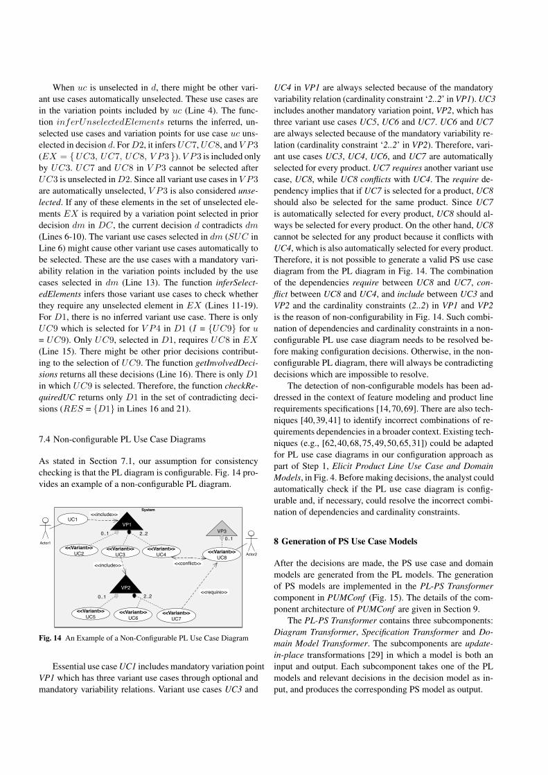
When uc is unselected in d, there might be other vari-ant use cases automatically unselected. These use cases arein the variation points included by uc (Line 4). The func-tion inferUnselectedElements returns the inferred, un-selected use cases and variation points for use case uc uns-elected in decision d. For D2, it infers UC7, UC8, and V P3
(EX = {UC3, UC7, UC8, V P3 }). V P3 is included onlyby UC3. UC7 and UC8 in V P3 cannot be selected afterUC3 is unselected in D2. Since all variant use cases in V P3
are automatically unselected, V P3 is also considered unse-lected. If any of these elements in the set of unselected ele-ments EX is required by a variation point selected in priordecision dm in DC, the current decision d contradicts dm
(Lines 6-10). The variant use cases selected in dm (SUC inLine 6) might cause other variant use cases automatically tobe selected. These are the use cases with a mandatory vari-ability relation in the variation points included by the usecases selected in dm (Line 13). The function inferSelect-edElements infers those variant use cases to check whetherthey require any unselected element in EX (Lines 11-19).For D1, there is no inferred variant use case. There is onlyUC9 which is selected for V P4 in D1 (I = {UC9} for u= UC9). Only UC9, selected in D1, requires UC8 in EX
(Line 15). There might be other prior decisions contribut-ing to the selection of UC9. The function getInvolvedDeci-sions returns all these decisions (Line 16). There is only D1
in which UC9 is selected. Therefore, the function checkRe-quiredUC returns only D1 in the set of contradicting deci-sions (RES = {D1} in Lines 16 and 21).
7.4 Non-configurable PL Use Case Diagrams
As stated in Section 7.1, our assumption for consistencychecking is that the PL diagram is configurable. Fig. 14 pro-vides an example of a non-configurable PL diagram.
System
Actor1
UC1
VP3
<<Variant>>UC8
<<include>>
0..1
<<Variant>>UC2
<<Variant>>UC3
0..1
VP1
2..2
Actor2<<Variant>>
UC4
VP2
<<Variant>>UC7
<<Variant>>UC6
2..2
<<include>> <<conflict>>
<<require>>
<<Variant>>UC5
0..1
Fig. 14 An Example of a Non-Configurable PL Use Case Diagram
Essential use case UC1 includes mandatory variation pointVP1 which has three variant use cases through optional andmandatory variability relations. Variant use cases UC3 and
UC4 in VP1 are always selected because of the mandatoryvariability relation (cardinality constraint ‘2..2’ in VP1). UC3includes another mandatory variation point, VP2, which hasthree variant use cases UC5, UC6 and UC7. UC6 and UC7are always selected because of the mandatory variability re-lation (cardinality constraint ‘2..2’ in VP2). Therefore, vari-ant use cases UC3, UC4, UC6, and UC7 are automaticallyselected for every product. UC7 requires another variant usecase, UC8, while UC8 conflicts with UC4. The require de-pendency implies that if UC7 is selected for a product, UC8should also be selected for the same product. Since UC7is automatically selected for every product, UC8 should al-ways be selected for every product. On the other hand, UC8cannot be selected for any product because it conflicts withUC4, which is also automatically selected for every product.Therefore, it is not possible to generate a valid PS use casediagram from the PL diagram in Fig. 14. The combinationof the dependencies require between UC8 and UC7, con-flict between UC8 and UC4, and include between UC3 andVP2 and the cardinality constraints (2..2) in VP1 and VP2is the reason of non-configurability in Fig. 14. Such combi-nation of dependencies and cardinality constraints in a non-configurable PL use case diagram needs to be resolved be-fore making configuration decisions. Otherwise, in the non-configurable PL diagram, there will always be contradictingdecisions which are impossible to resolve.
The detection of non-configurable models has been ad-dressed in the context of feature modeling and product linerequirements specifications [14,70,69]. There are also tech-niques [40,39,41] to identify incorrect combinations of re-quirements dependencies in a broader context. Existing tech-niques (e.g., [62,40,68,75,49,50,65,31]) could be adaptedfor PL use case diagrams in our configuration approach aspart of Step 1, Elicit Product Line Use Case and DomainModels, in Fig. 4. Before making decisions, the analyst couldautomatically check if the PL use case diagram is config-urable and, if necessary, could resolve the incorrect combi-nation of dependencies and cardinality constraints.
8 Generation of PS Use Case Models
After the decisions are made, the PS use case and domainmodels are generated from the PL models. The generationof PS models are implemented in the PL-PS Transformercomponent in PUMConf (Fig. 15). The details of the com-ponent architecture of PUMConf are given in Section 9.
The PL-PS Transformer contains three subcomponents:Diagram Transformer, Specification Transformer and Do-main Model Transformer. The subcomponents are update-in-place transformations [29] in which a model is both aninput and output. Each subcomponent takes one of the PLmodels and relevant decisions in the decision model as in-put, and produces the corresponding PS model as output.

PL Use Case Diagram
Diagram Decisions in
Decision Model
PL Use Case Specifications
Specification Decisions in
Decision Model
AnnotatedPL Use Case
Specifications
PL Domain Model
Domain Model Decisions in
Decision Model
PL-PS Transformer
Diagram Transformer
Specification Transformer
Domain Model
Transformer
PS Use CaseDiagram
PS Use Case Specifications
PS Domain Model
GATE NLPWorkbench JAPEJAPEJAPEJAPE
Fig. 15 Overview of the PS Use Case and Domain Model Generation
All PL and PS use case specifications are stored as plaintext in the native IBM DOORS format. During the consis-tency checking of use case and domain models (see Step2 in Fig. 4), for the RUCM keywords and types of steps,use case specifications in IBM DOORS are annotated us-ing NLP provided by the GATE workbench (see Section 9).The Specification Transformer uses the annotations to dis-tinguish RUCM steps and types of alternative flows in match-ing transformation rules (Section 9). It processes the plaintext instead of instances of the RUCM metamodel [81]. Com-pared to model transformation languages, Java provides muchmore flexibility for handling annotated plain text in terms ofloading, matching and editing the text. Therefore, we usedJava to implement the Specification Transformer. To providethe uniformity in the PL-PS Transformer, other subcompo-nents are also implemented in Java.
The Diagram Transformer takes the PL use case dia-gram and diagram decisions as input, and generates the PSuse case diagram as output. The PS diagram generation isbased on mappings between patterns in PL and PS diagramsdriven by decisions. For instance, for a variant use case inthe PL diagram, there is a corresponding use case in thePS diagram only if the variant use case is selected duringdecision-making. Fig. 16 gives example source and targetpatterns with decisions for use case diagrams.
Fig. 16 has three columns, i.e., source pattern, decision,and target pattern, to represent example mappings betweenPL and PS diagrams. Decisions for the diagrams are rep-resented as quadruples (see Section 7). In Fig. 16(a), theanalyst selects all variant use cases in mandatory variationpoint X included by essential use case UC. The variationpoint, include relation and unselected variant use cases areremoved while each selected variant use case is transformedinto a use case included by UC in the PS diagram. In Fig. 16(b),optional variation point X is included by essential use caseUC while all variant use cases are unselected. Only essen-
UC
<<Variant>>UCn
<<include>>
VariationPoint X
max = min
<<Variant>>UC1 …
min > 0
Actor
UC
UCn
<<include>>UC1
<<include>>
…
Actor
Source Pattern Target PatternDecision
(X, UC, {UC1,…, UCn}, ⦰)
<<Variant>>UCn
VariationPoint X
max >= min
<<Variant>>UC1 …
min = 0
UC <<include>>
Actor
UC
Actor
(X, UC, ⦰, {UC1,…, UCn})
VariationPoint X
max = 1
<<Variant>>UC1
min = 0
Actor
(X, null, {UC1}, ⦰) UC1
Actor
(a)
(b)
(c)
Fig. 16 Example Source and Target Patterns with Decisions for UseCase Diagrams
tial use case X is kept in the PS diagram. The source patternin Fig. 16(c) represents optional variation point X which hasone variant use case (i.e., UC1). X is not included by anyother essential or variant use case. When UC1 is selected,only variation point X is removed from the PS diagram.
The Specification Transformer takes both diagram andspecification decisions to generate PS use case specifica-tions (see Fig. 17 for example mappings between PL and PSspecifications). Diagram decisions are used to transform usecase steps where variation points are included. In Fig. 17(a),the source pattern represents an example specification wherethe variation point X in Fig. 16(a) is included in betweenother use case steps. For the same decision, represented as aquadruple, in Fig. 16(a) where all variant use cases are se-lected, the VALIDATES THAT and INCLUDE steps in thebasic flow and a set of alternative flows are generated forthe PS specification. One of the variant use cases (UC1) isexecuted in the basic flow (the step where UC1 is included)if its precondition holds (the VALIDATES THAT step). Therest of the selected use cases are executed in the generatedalternative flows. One of the alternative flows is taken ifthe VALIDATES THAT statement in the basic flow fails. InFig. 17(b), the source PL specification for Fig. 16(b) is trans-formed into the PS specification based on the diagram deci-sion where no variant use case is selected. The step wherethe variation point X is included is removed for the PS spec-ification.
Fig. 17(c) represents an example source pattern whichcontains multiple optional steps in a variant order. The an-alyst has to decide which optional steps are retained and inwhich order in the PS specification. The specification deci-sion for each optional step is represented as a triple of thestep name, a boolean variable which is true when the step is
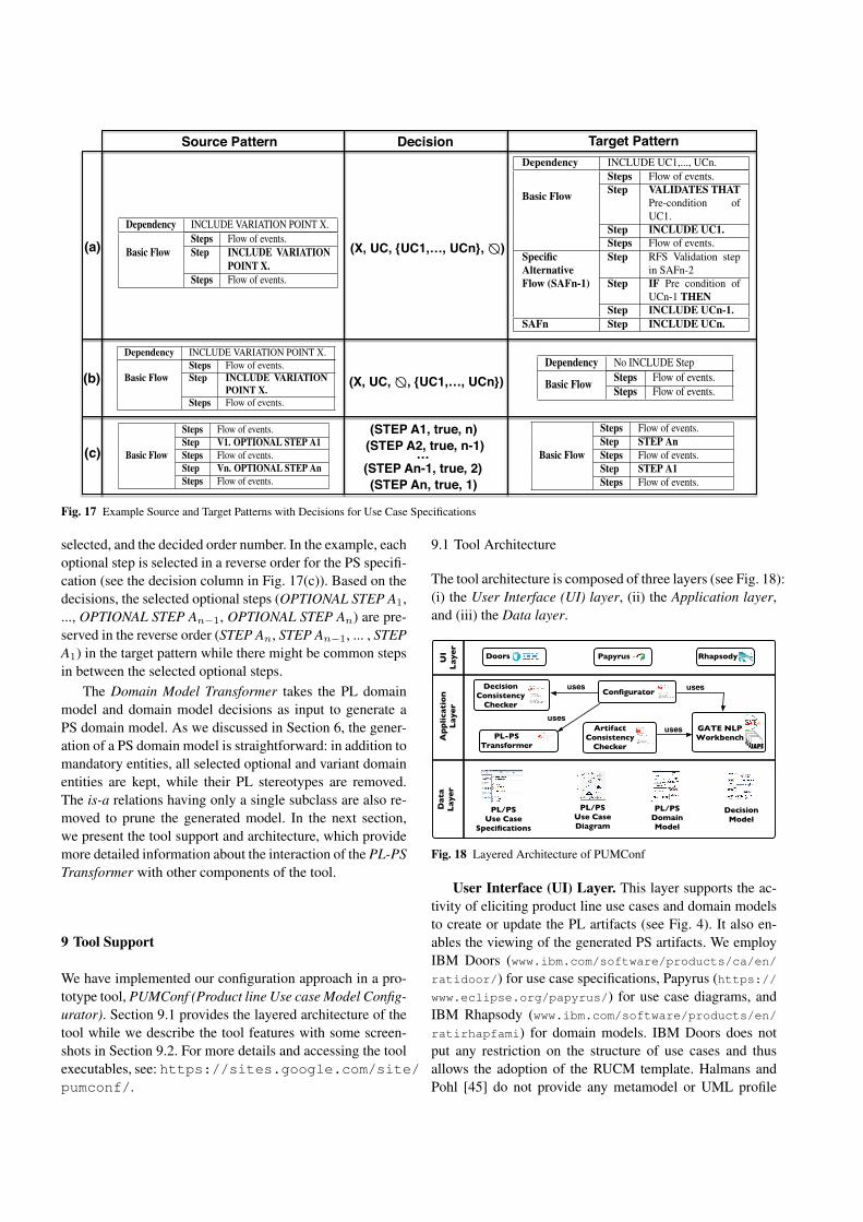
Source Pattern Target PatternDecision
(X, UC, {UC1,…, UCn}, ⦰)
(X, UC, ⦰, {UC1,…, UCn})
(STEP A1, true, n)
(a)
(b)
(c)
Dependency INCLUDE VARIATION POINT X.
Basic FlowSteps Flow of events.Step INCLUDE VARIATION
POINT X.Steps Flow of events.
Dependency INCLUDE UC1,..., UCn.
Basic Flow
Steps Flow of events.Step VALIDATES THAT
Pre-condition ofUC1.
Step INCLUDE UC1.Steps Flow of events.
SpecificAlternativeFlow (SAFn-1)
Step RFS Validation stepin SAFn-2
Step IF Pre condition ofUCn-1 THEN
Step INCLUDE UCn-1.SAFn Step INCLUDE UCn.
Dependency INCLUDE VARIATION POINT X.
Basic FlowSteps Flow of events.Step INCLUDE VARIATION
POINT X.Steps Flow of events.
Dependency No INCLUDE Step
Basic Flow Steps Flow of events.Steps Flow of events.
Basic Flow
Steps Flow of events.Step V1. OPTIONAL STEP A1Steps Flow of events.Step Vn. OPTIONAL STEP AnSteps Flow of events.
Basic Flow
Steps Flow of events.Step STEP AnSteps Flow of events.Step STEP A1Steps Flow of events.
(STEP An-1, true, 2)(STEP An, true, 1)
(STEP A2, true, n-1)…
Fig. 17 Example Source and Target Patterns with Decisions for Use Case Specifications
selected, and the decided order number. In the example, eachoptional step is selected in a reverse order for the PS specifi-cation (see the decision column in Fig. 17(c)). Based on thedecisions, the selected optional steps (OPTIONAL STEP A1,..., OPTIONAL STEP An−1, OPTIONAL STEP An) are pre-served in the reverse order (STEP An, STEP An−1, ... , STEPA1) in the target pattern while there might be common stepsin between the selected optional steps.
The Domain Model Transformer takes the PL domainmodel and domain model decisions as input to generate aPS domain model. As we discussed in Section 6, the gener-ation of a PS domain model is straightforward: in addition tomandatory entities, all selected optional and variant domainentities are kept, while their PL stereotypes are removed.The is-a relations having only a single subclass are also re-moved to prune the generated model. In the next section,we present the tool support and architecture, which providemore detailed information about the interaction of the PL-PSTransformer with other components of the tool.
9 Tool Support
We have implemented our configuration approach in a pro-totype tool, PUMConf (Product line Use case Model Config-urator). Section 9.1 provides the layered architecture of thetool while we describe the tool features with some screen-shots in Section 9.2. For more details and accessing the toolexecutables, see: https://sites.google.com/site/pumconf/.
9.1 Tool Architecture
The tool architecture is composed of three layers (see Fig. 18):(i) the User Interface (UI) layer, (ii) the Application layer,and (iii) the Data layer.
Doors PapyrusUI
Laye
r
Rhapsody
App
licat
ion
Laye
rD
ata
Laye
r
PL/PS Use Case
Specifications
ArtifactConsistency
Checker
PL/PS Use Case Diagram
PL/PS Domain Model
GATE NLPWorkbench JAPEJAPEJAPEJAPE
usesConfigurator
Decision Model
uses
DecisionConsistency
Checker
PL-PSTransformer
uses
uses
Fig. 18 Layered Architecture of PUMConf
User Interface (UI) Layer. This layer supports the ac-tivity of eliciting product line use cases and domain modelsto create or update the PL artifacts (see Fig. 4). It also en-ables the viewing of the generated PS artifacts. We employIBM Doors (www.ibm.com/software/products/ca/en/ratidoor/) for use case specifications, Papyrus (https://www.eclipse.org/papyrus/) for use case diagrams, andIBM Rhapsody (www.ibm.com/software/products/en/ratirhapfami) for domain models. IBM Doors does notput any restriction on the structure of use cases and thusallows the adoption of the RUCM template. Halmans andPohl [45] do not provide any metamodel or UML profile
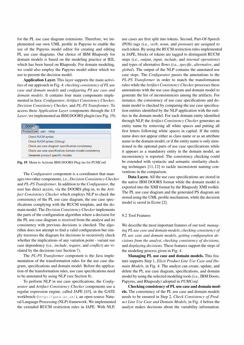
for the PL use case diagram extensions. Therefore, we im-plemented our own UML profile in Papyrus to enable theuse of the Papyrus model editor for creating and editingPL use case diagrams. Our choice of IBM Rhapsody fordomain models is based on the modeling practice at IEE,which has been based on Rhapsody. For domain modeling,we could also employ the Papyrus model editor which weuse to present the decision model.
Application Layer. This layer supports the main activi-ties of our approach in Fig. 4: checking consistency of PL usecase and domain models and configuring PS use case anddomain models. It contains four main components imple-mented in Java: Configurator, Artifact Consistency Checker,Decision Consistency Checker, and PL-PS Transformer. Toaccess these Application Layer components through the UILayer, we implemented an IBM DOORS plugin (see Fig. 19).
Fig. 19 Menu to Activate IBM DOORS Plug-ins for PUMConf
The Configurator component is a coordinator that man-ages two other components, i.e., Decision Consistency Checkerand PL-PS Transformer. In addition to the Configurator, theuser has direct access, via the DOORS plug-in, to the Arti-fact Consistency Checker which employs NLP to check theconsistency of the PL use case diagram, the use case spec-ifications complying with the RUCM template, and the do-main model. The Decision Consistency Checker implementsthe parts of the configuration algorithm where a decision forthe PL use case diagram is received from the analyst and itsconsistency with previous decisions is checked. The algo-rithm does not attempt to find a valid configuration but sim-ply traverses the diagram for decisions to recursively checkwhether the implications of any variation point - variant usecase dependency (i.e., include, require, and conflict) are vi-olated by the decisions (see Section 7).
The PL-PS Transformer component is the Java imple-mentation of the transformation rules for the use case dia-gram, specifications and domain model. Before the applica-tion of the transformation rules, use case specifications needto be annotated by using NLP (see Section 8).
To perform NLP in use case specifications, the Config-urator and Artifact Consistency Checker components use aregular expression engine, called JAPE [43], in the GATEworkbench (http://gate.ac.uk/), an open-source Natu-ral Language Processing (NLP) framework. We implementedthe extended RUCM restriction rules in JAPE. With NLP,
use cases are first split into tokens. Second, Part-Of-Speech(POS) tags (i.e., verb, noun, and pronoun) are assigned toeach token. By using the RUCM restriction rules implementedin JAPE, blocks of tokens are tagged to distinguish RUCMsteps (i.e., output, input, include, and internal operations)and types of alternative flows (i.e., specific, alternative, andglobal). The output of the NLP contains the annotated usecase steps. The Configurator passes the annotations to thePL-PS Transformer in order to match the transformationrules while the Artifact Consistency Checker processes theseannotations with the use case diagram and domain model togenerate the list of inconsistencies among the artifacts. Forinstance, the consistency of use case specifications and do-main model is checked by comparing the use case specifica-tion entities identified by the NLP application with the enti-ties in the domain model. For each domain entity identifiedthrough NLP, the Artifact Consistency Checker generates anentity name by removing all white spaces and putting allfirst letters following white spaces in capital. If the entityname does not appear either as class name or as an attributename in the domain model, or if the entity name is only men-tioned in the optional parts of use case specifications whileit appears as a mandatory entity in the domain model, aninconsistency is reported. The consistency checking couldbe extended with syntactic and semantic similarity check-ing techniques [11,12] to tackle inconsistent naming con-ventions in the comparison.
Data Layer. All the use case specifications are stored inthe native IBM DOORS format while the domain model isexported into the XMI format by the Rhapsody XMI toolkit.The PL use case diagram and the generated PS diagram arestored using the UML profile mechanism, while the decisionmodel is saved in Ecore [2].
9.2 Tool Features
We describe the most important features of our tool: manag-ing PL use case and domain models, checking consistency ofPL use case and domain models, getting configuration de-cisions from the analyst, checking consistency of decisions,and displaying decisions. These features support the steps ofthe modeling process given in Fig. 4.
Managing PL use case and domain models. This fea-ture supports Step 1, Elicit Product Line Use Case and Do-main Models, in Fig. 4. The analyst can create, update, anddelete the PL use case diagram, specifications, and domainmodel by using the selected modeling tools (i.e., IBM Doors,Papyrus, and Rhapsody) adopted in PUMConf.
Checking consistency of PL use case and domain mod-els. The consistency of the PL use case and domain modelsneeds to be ensured in Step 2, Check Consistency of Prod-uct Line Use Case and Domain Models, in Fig. 4 before theanalyst makes decisions about the variability information.
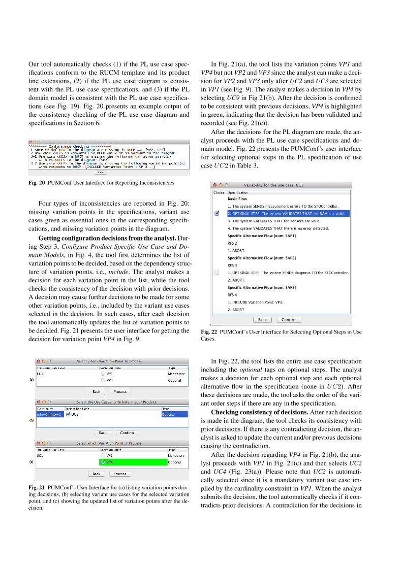
Our tool automatically checks (1) if the PL use case spec-ifications conform to the RUCM template and its productline extensions, (2) if the PL use case diagram is consis-tent with the PL use case specifications, and (3) if the PLdomain model is consistent with the PL use case specifica-tions (see Fig. 19). Fig. 20 presents an example output ofthe consistency checking of the PL use case diagram andspecifications in Section 6.
Fig. 20 PUMConf User Interface for Reporting Inconsistencies
Four types of inconsistencies are reported in Fig. 20:missing variation points in the specifications, variant usecases given as essential ones in the corresponding specifi-cations, and missing variation points in the diagram.
Getting configuration decisions from the analyst. Dur-ing Step 3, Configure Product Specific Use Case and Do-main Models, in Fig. 4, the tool first determines the list ofvariation points to be decided, based on the dependency struc-ture of variation points, i.e., include. The analyst makes adecision for each variation point in the list, while the toolchecks the consistency of the decision with prior decisions.A decision may cause further decisions to be made for someother variation points, i.e., included by the variant use casesselected in the decision. In such cases, after each decisionthe tool automatically updates the list of variation points tobe decided. Fig. 21 presents the user interface for getting thedecision for variation point VP4 in Fig. 9.
Fig. 21 PUMConf’s User Interface for (a) listing variation points driv-ing decisions, (b) selecting variant use cases for the selected variationpoint, and (c) showing the updated list of variation points after the de-cision.
In Fig. 21(a), the tool lists the variation points VP1 andVP4 but not VP2 and VP3 since the analyst can make a deci-sion for VP2 and VP3 only after UC2 and UC3 are selectedin VP1 (see Fig. 9). The analyst makes a decision in VP4 byselecting UC9 in Fig 21(b). After the decision is confirmedto be consistent with previous decisions, VP4 is highlightedin green, indicating that the decision has been validated andrecorded (see Fig. 21(c)).
After the decisions for the PL diagram are made, the an-alyst proceeds with the PL use case specifications and do-main model. Fig. 22 presents the PUMConf’s user interfacefor selecting optional steps in the PL specification of usecase UC2 in Table 3.
Fig. 22 PUMConf’s User Interface for Selecting Optional Steps in UseCases.
In Fig. 22, the tool lists the entire use case specificationincluding the optional tags on optional steps. The analystmakes a decision for each optional step and each optionalalternative flow in the specification (none in UC2). Afterthese decisions are made, the tool asks the order of the vari-ant order steps if there are any in the specification.
Checking consistency of decisions. After each decisionis made in the diagram, the tool checks its consistency withprior decisions. If there is any contradicting decision, the an-alyst is asked to update the current and/or previous decisionscausing the contradiction.
After the decision regarding VP4 in Fig. 21(b), the ana-lyst proceeds with VP1 in Fig. 21(c) and then selects UC2and UC4 (Fig. 23(a)). Please note that UC2 is automati-cally selected since it is a mandatory variant use case im-plied by the cardinality constraint in VP1. When the analystsubmits the decision, the tool automatically checks if it con-tradicts prior decisions. A contradiction for the decisions in
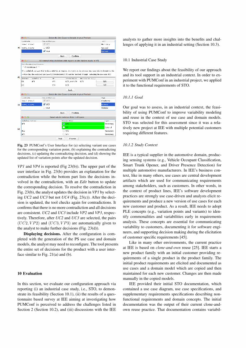
Fig. 23 PUMConf’s User Interface for (a) selecting variant use casesfor the corresponding variation point, (b) explaining the contradictingdecisions, (c) updating the contradicting decision, and (d) showing theupdated list of variation points after the updated decision.
VP1 and VP4 is reported (Fig 23(b)). The upper part of theuser interface in Fig. 23(b) provides an explanation for thecontradiction while the bottom part lists the decisions in-volved in the contradiction, with an Edit button to updatethe corresponding decision. To resolve the contradiction inFig. 23(b), the analyst updates the decision in VP1 by select-ing UC2 and UC3 but not UC4 (Fig. 23(c)). After the deci-sion is updated, the tool checks again for contradictions. Itconfirms that there is no more contradiction and all decisionsare consistent. UC2 and UC3 include VP2 and VP3, respec-tively. Therefore, after UC2 and UC3 are selected, the pairs(UC2, V P2) and (UC3, V P3) are automatically given tothe analyst to make further decisions (Fig. 23(d)).
Displaying decisions. After the configuration is com-pleted with the generation of the PS use case and domainmodels, the analyst may need to reconfigure. The tool presentsthe entire set of decisions for the product with a user inter-face similar to Fig. 21(a) and (b).
10 Evaluation
In this section, we evaluate our configuration approach viareporting (i) an industrial case study, i.e., STO, to demon-strate its feasibility (Section 10.1), (ii) the results of a ques-tionnaire based survey at IEE aiming at investigating howPUMConf is perceived to address the challenges listed inSection 2 (Section 10.2), and (iii) discussions with the IEE
analysts to gather more insights into the benefits and chal-lenges of applying it in an industrial setting (Section 10.3).
10.1 Industrial Case Study
We report our findings about the feasibility of our approachand its tool support in an industrial context. In order to ex-periment with PUMConf in an industrial project, we appliedit to the functional requirements of STO.
10.1.1 Goal
Our goal was to assess, in an industrial context, the feasi-bility of using PUMConf to improve variability modelingand reuse in the context of use case and domain models.STO was selected for this assessment since it was a rela-tively new project at IEE with multiple potential customersrequiring different features.
10.1.2 Study Context
IEE is a typical supplier in the automotive domain, produc-ing sensing systems (e.g., Vehicle Occupant Classification,Smart Trunk Opener, and Driver Presence Detection) formultiple automotive manufacturers. In IEE’s business con-text, like in many others, use cases are central developmentartifacts which are used for communicating requirementsamong stakeholders, such as customers. In other words, inthe context of product lines, IEE’s software developmentpractices are strongly use case-driven and analysts elicit re-quirements and produce a new version of use cases for eachnew customer and product. As a result, IEE needs to adoptPLE concepts (e.g., variation points and variants) to iden-tify commonalities and variabilities early in requirementsanalysis. These concepts are essential for communicatingvariability to customers, documenting it for software engi-neers, and supporting decision making during the elicitationof customer specific requirements [45].
Like in many other environments, the current practiceat IEE is based on clone-and-own reuse [25]. IEE starts anew product family with an initial customer providing re-quirements of a single product in the product family. Theinitial product requirements are elicited and documented asuse cases and a domain model which are copied and thenmaintained for each new customer. Changes are then mademanually in the copied models.
IEE provided their initial STO documentation, whichcontained a use case diagram, use case specifications, andsupplementary requirements specifications describing non-functional requirements and domain concepts. The initialdocumentation was the output of their current clone-and-own reuse practice. That documentation contains variabil-
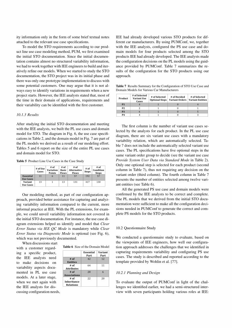
ity information only in the form of some brief textual notesattached to the relevant use case specifications.
To model the STO requirements according to our prod-uct line use case modeling method, PUM, we first examinedthe initial STO documentation. Since the initial documen-tation contains almost no structured variability information,we had to work together with IEE engineers to build and iter-atively refine our models. When we started to study the STOdocumentation, the STO project was in its initial phase andthere was only one prototype implementation to discuss withsome potential customers. One may argue that it is not al-ways easy to identify variations in requirements when a newproject starts. However, the IEE analysts stated that, most ofthe time in their domain of applications, requirements andtheir variability can be identified with the first customer.
10.1.3 Results
After studying the initial STO documentation and meetingwith the IEE analysts, we built the PL use cases and domainmodel for STO. The diagram in Fig. 6, the use case specifi-cations in Table 2, and the domain model in Fig. 7 are part ofthe PL models we derived as a result of our modeling effort.Tables 5 and 6 report on the size of the entire PL use casesand domain model for STO.
Table 5 Product Line Use Cases in the Case Study
#ofUseCases
#ofVariationPoints
#ofBasicFlows
#ofAlternativeFlows
#ofSteps
#ofConditionSteps
EssentialUseCases
11 6 11 57 192 57
VariantUseCases
13 1 13 131 417 130
Our modeling method, as part of our configuration ap-proach, provided better assistance for capturing and analyz-ing variability information compared to the current, moreinformal practice at IEE. With the PL extensions, for exam-ple, we could unveil variability information not covered inthe initial STO documentation. For instance, the use case di-agram extensions helped us identify and model that ClearError Status via IEE QC Mode is mandatory while ClearError Status via Diagnostic Mode is optional (see Fig. 6),which was not previously documented.
Table 6 Size of the Domain Model
! Essential!Part!
Variant!Part!
#!of!!Entities!
42# 12#
#!of!!Attributes!
64# 11#
#!of!Associations!
28# 6#
#!of!Inheritance!Relations!
22# 20#
#
When discussions startwith a customer regard-ing a specific product,the IEE analysts needto make decisions onvariability aspects docu-mented in PL use casemodels. At a later stage,when we met again withthe IEE analysts for dis-cussing configuration needs,
IEE had already developed various STO products for dif-ferent car manufacturers. By using PUMConf, we, togetherwith the IEE analysts, configured the PS use case and do-main models for four products selected among the STOproducts IEE had already developed. The IEE analysts madethe configuration decisions on the PL models using the guid-ance provided by PUMConf. Table 7 summarizes the re-sults of the configuration for the STO products using ourapproach.
Table 7 Results Summary for the Configuration of STO Use Case andDomain Models for Various Car Manufacturers
Product#ofSelectedVariantUse
Cases
#ofSelectedOptionalSteps
#ofDecidedVariantOrders
#ofSelectedVariantEntities
P1 4 1 0 4P2 2 1 0 1P3 6 1 0 5P4 4 1 0 3
The first column is the number of variant use cases se-lected by the analysts for each product. In the PL use casediagram, there are six variant use cases with a mandatoryvariability relation, which are automatically selected. Ta-ble 7 does not include the automatically selected variant usecases. The PL specifications have five optional steps in thesame variant order group to decide (see the variant use caseProvide System User Data via Standard Mode in Table 2).Only one optional step is selected for each product (secondcolumn in Table 7), thus not requiring any decision on thevariant order (third column). The fourth column in Table 7presents the number of entities selected among twelve vari-ant entities (see Table 6).
All the generated PS use case and domain models wereconfirmed by the IEE analysts to be correct and complete.The PL models that we derived from the initial STO docu-mentation were sufficient to make all the configuration deci-sions needed in PUMConf to generate the correct and com-plete PS models for the STO products.
10.2 Questionnaire Study
We conducted a questionnaire study to evaluate, based onthe viewpoints of IEE engineers, how well our configura-tion approach addresses the challenges that we identified incapturing requirements variability and configuring PS usecases. The study is described and reported according to thetemplate provided by Wohlin et al. [77].
10.2.1 Planning and Design
To evaluate the output of PUMConf in light of the chal-lenges we identified earlier, we had a semi-structured inter-view with seven participants holding various roles at IEE:
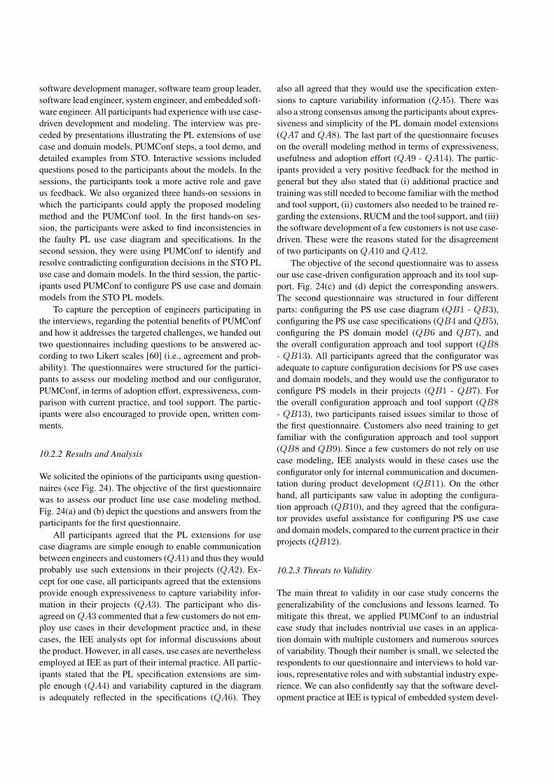
software development manager, software team group leader,software lead engineer, system engineer, and embedded soft-ware engineer. All participants had experience with use case-driven development and modeling. The interview was pre-ceded by presentations illustrating the PL extensions of usecase and domain models, PUMConf steps, a tool demo, anddetailed examples from STO. Interactive sessions includedquestions posed to the participants about the models. In thesessions, the participants took a more active role and gaveus feedback. We also organized three hands-on sessions inwhich the participants could apply the proposed modelingmethod and the PUMConf tool. In the first hands-on ses-sion, the participants were asked to find inconsistencies inthe faulty PL use case diagram and specifications. In thesecond session, they were using PUMConf to identify andresolve contradicting configuration decisions in the STO PLuse case and domain models. In the third session, the partic-ipants used PUMConf to configure PS use case and domainmodels from the STO PL models.
To capture the perception of engineers participating inthe interviews, regarding the potential benefits of PUMConfand how it addresses the targeted challenges, we handed outtwo questionnaires including questions to be answered ac-cording to two Likert scales [60] (i.e., agreement and prob-ability). The questionnaires were structured for the partici-pants to assess our modeling method and our configurator,PUMConf, in terms of adoption effort, expressiveness, com-parison with current practice, and tool support. The partic-ipants were also encouraged to provide open, written com-ments.
10.2.2 Results and Analysis
We solicited the opinions of the participants using question-naires (see Fig. 24). The objective of the first questionnairewas to assess our product line use case modeling method.Fig. 24(a) and (b) depict the questions and answers from theparticipants for the first questionnaire.
All participants agreed that the PL extensions for usecase diagrams are simple enough to enable communicationbetween engineers and customers (QA1) and thus they wouldprobably use such extensions in their projects (QA2). Ex-cept for one case, all participants agreed that the extensionsprovide enough expressiveness to capture variability infor-mation in their projects (QA3). The participant who dis-agreed on QA3 commented that a few customers do not em-ploy use cases in their development practice and, in thesecases, the IEE analysts opt for informal discussions aboutthe product. However, in all cases, use cases are neverthelessemployed at IEE as part of their internal practice. All partic-ipants stated that the PL specification extensions are sim-ple enough (QA4) and variability captured in the diagramis adequately reflected in the specifications (QA6). They
also all agreed that they would use the specification exten-sions to capture variability information (QA5). There wasalso a strong consensus among the participants about expres-siveness and simplicity of the PL domain model extensions(QA7 and QA8). The last part of the questionnaire focuseson the overall modeling method in terms of expressiveness,usefulness and adoption effort (QA9 - QA14). The partic-ipants provided a very positive feedback for the method ingeneral but they also stated that (i) additional practice andtraining was still needed to become familiar with the methodand tool support, (ii) customers also needed to be trained re-garding the extensions, RUCM and the tool support, and (iii)the software development of a few customers is not use case-driven. These were the reasons stated for the disagreementof two participants on QA10 and QA12.
The objective of the second questionnaire was to assessour use case-driven configuration approach and its tool sup-port. Fig. 24(c) and (d) depict the corresponding answers.The second questionnaire was structured in four differentparts: configuring the PS use case diagram (QB1 - QB3),configuring the PS use case specifications (QB4 and QB5),configuring the PS domain model (QB6 and QB7), andthe overall configuration approach and tool support (QB8
- QB13). All participants agreed that the configurator wasadequate to capture configuration decisions for PS use casesand domain models, and they would use the configurator toconfigure PS models in their projects (QB1 - QB7). Forthe overall configuration approach and tool support (QB8
- QB13), two participants raised issues similar to those ofthe first questionnaire. Customers also need training to getfamiliar with the configuration approach and tool support(QB8 and QB9). Since a few customers do not rely on usecase modeling, IEE analysts would in these cases use theconfigurator only for internal communication and documen-tation during product development (QB11). On the otherhand, all participants saw value in adopting the configura-tion approach (QB10), and they agreed that the configura-tor provides useful assistance for configuring PS use caseand domain models, compared to the current practice in theirprojects (QB12).
10.2.3 Threats to Validity
The main threat to validity in our case study concerns thegeneralizability of the conclusions and lessons learned. Tomitigate this threat, we applied PUMConf to an industrialcase study that includes nontrivial use cases in an applica-tion domain with multiple customers and numerous sourcesof variability. Though their number is small, we selected therespondents to our questionnaire and interviews to hold var-ious, representative roles and with substantial industry expe-rience. We can also confidently say that the software devel-opment practice at IEE is typical of embedded system devel-
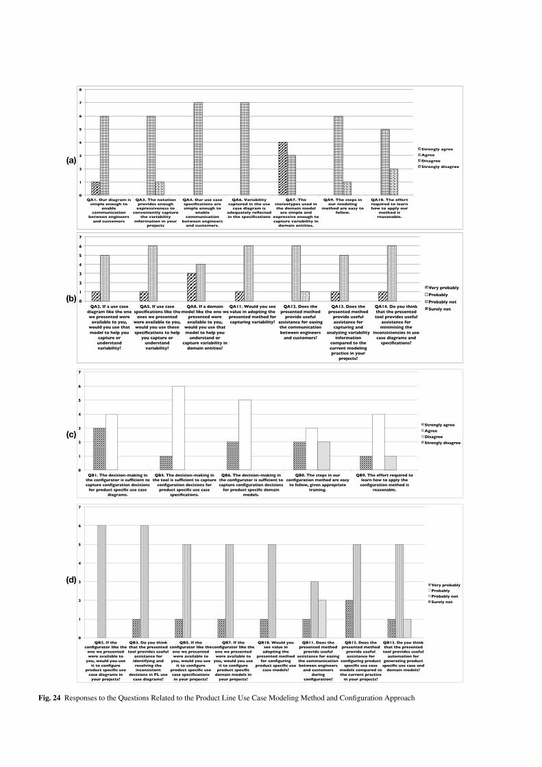
(a)
0!
1!
2!
3!
4!
5!
6!
7!
8!
QA1. Our diagram is simple enough to
enable communication
between engineers and customers!
QA3. The notation provides enough
expressiveness to conveniently capture
the variability information in your
projects!
QA4. Our use case specifications are simple enough to
enable communication
between engineers and customers.!
QA6. Variability captured in the use
case diagram is adequately reflected in the specifications!
QA7. The stereotypes used in the domain model
are simple and expressive enough to capture variability in
domain entities.!
QA9. The steps in our modeling
method are easy to follow.!
QA10. The effort required to learn how to apply our
method is reasonable. !
Strongly agree!Agree!Disagree!Strongly disagree!
(b) 0!
1!
2!
3!
4!
5!
6!
7!
QA2. If a use case diagram like the one we presented were
available to you, would you use that model to help you
capture or understand variability?!
QA5. If use case specifications like the
ones we presented were available to you, would you use those specifications to help
you capture or understand variability?!
QA8. If a domain model like the one we
presented were available to you,
would you use that model to help you
understand or capture variability in
domain entities?!
QA11. Would you see value in adopting the presented method for capturing variability?!
QA12. Does the presented method
provide useful assistance for easing the communication between engineers
and customers?!
QA13. Does the presented method
provide useful assistance for capturing and
analyzing variability information
compared to the current modeling practice in your
projects?!
QA14. Do you think that the presented tool provides useful
assistance for minimising the
inconsistencies in use case diagrams and
specifications?!
Very probably!Probably!Probably not!Surely not!
(c)
(d)
0!
1!
2!
3!
4!
5!
6!
7!
QB1. The decision-making in the configurator is sufficient to capture configuration decisions
for product specific use case diagrams.!
QB4. The decision-making in the tool is sufficient to capture
configuration decisions for product specific use case
specifications.!
QB6. The decision-making in the configurator is sufficient to capture configuration decisions
for product specific domain models.!
QB8. The steps in our configuration method are easy
to follow, given appropriate training.!
QB9. The effort required to learn how to apply the
configuration method is reasonable. !
Strongly agree!Agree!Disagree!Strongly disagree!
0!
1!
2!
3!
4!
5!
6!
7!
QB2. If the configurator like the
one we presented were available to
you, would you use it to configure
product specific use case diagrams in
your projects?!
QB3. Do you think that the presented tool provides useful
assistance for identifying and resolving the inconsistent
decisions in PL use case diagrams?!
QB5. If the configurator like the
one we presented were available to
you, would you use it to configure
product specific use case specifications in your projects?!
QB7. If the configurator like the
one we presented were available to
you, would you use it to configure
product specific domain models in
your projects?!
QB10. Would you see value in adopting the
presented method for configuring
product specific use case models?!
QB11. Does the presented method
provide useful assistance for easing the communication between engineers
and customers during
configuration?!
QB12. Does the presented method
provide useful assistance for
configuring product specific use case
models compared to the current practice
in your projects?!
QB13. Do you think that the presented tool provides useful
automation for generating product
specific use case and domain models?!
Very probably!Probably!Probably not!Surely not!
Fig. 24 Responses to the Questions Related to the Product Line Use Case Modeling Method and Configuration Approach
opment in the automotive domain. To limit threats to internalvalidity, we had many meetings with the IEE analysts in theSTO project to verify the correctness and completeness ofour models.
10.3 Discussions with the Analysts and Engineers
The questionnaire study had open, written comments un-der each section, in which the participants could state theiropinions in a few sentences about how PUMConf addressesthe challenges reported in Section 2. As reported in Sec-tion 10.2, the participants’ answers to the questions throughLikert scales and their open comments indicate that they seehigh value in adopting the configuration approach and itstool support in an industrial setting in terms of increasingreusability, minimizing modeling effort, and providing ef-fective automation. In order to elaborate over the open com-ments in the two questionnaires, we organized further dis-cussions with the participants. Based on the feedback in thecomments, we identified three aspects to discuss with theparticipants: modeling effort, degree of automation, and lim-itations of the configuration approach.
10.3.1 Modeling Effort
In the current practice at IEE, like in many other environ-ments, there is no systematic way to model variability infor-mation in use case and domain models. As mentioned be-fore, the IEE analysts take only brief notes attached to usecase specifications to indicate what may vary in the speci-fication. They are reluctant to use feature models traced touse case specifications because of two main issues: (i) hav-ing feature models requires considerable additional model-ing effort with manual assignment of traces at a very lowlevel of granularity, e.g., sequences of use case steps; and (ii)they find it hard and distracting to switch from feature mod-els to use cases and vice versa during the decision-makingprocess. The PL extensions in Section 5 enable the ana-lysts to model variability information directly in use caseand domain models without any feature modeling. The IEEanalysts stated that the effort required to apply the exten-sions for modeling variability information was reasonable.By having variability information in use case and domainmodels, the analysts could focus on one artifact at a timeto make configuration decisions. They considered the ex-tensions to be simple enough to enable communication be-tween analysts and customers, but they also mentioned thattraining customers may be more of a challenge since thecompany may need customers’ consent to adopt PUMConf.Thus, its costs and benefits should be made clear to cus-tomers.
10.3.2 Degree of Automation
In our discussions with the analysts at IEE, we noticed that:(i) the current clone-and-own reuse practice has no system-atic way and automated support to decide what to includein PS use case and domain models; (ii) typically, multipleanalysts and engineers from both the customer and suppliersides are involved in the decision-making process; (iii) theanalysts and engineers have to spend several days to man-ually review the entire set of requirements cloned from theprevious product; and (iv) the intended updates on the cloneduse case and domain models are manually carried out bythe IEE analysts. On the other hand, PUMConf consists ofvarious automated use case modeling and configuration ac-tivities in the context of product lines. The decision mak-ing process is automated in the sense that the IEE analystsare guided through the PL artifacts for collecting and verify-ing configuration decisions, while the generation of PS arti-facts does not require any human intervention. Using PUM-Conf, the IEE analysts only select a set of relevant variantuse cases, optional steps, and variant entities for a prod-uct. Corresponding PS use case and domain models are ob-tained from the PL models automatically, which greatly re-duces the complexity of the entire configuration process.Though modeling variability in PL models is mostly man-ual, PUMConf provides automatic consistency checking forthese models and feedback to the analyst to help them refineand correct the models. The IEE analysts considered the au-tomated consistency checking of decisions and the genera-tion of PS artifacts to be highly valuable.
10.3.3 Limitations of the Configuration Approach
Our configuration approach and tool support have some lim-itations at this current stage. First, our modeling methodsupports only functional requirements. As stated by IEE an-alysts, there are numerous types of non-functional require-ments (e.g., security, timing, and reliability) which may playa key role in variability associated with functional require-ments. It is crucial to capture and configure such aspects aswell. Second, we do not address and support the evolution ofPL use case and domain models. When a new project starts,requirements and their variations might not be fully known.As a result, in early stages, analysts are expected to redefinevariation points and variants in requirements specificationsthrough frequent iterations. We were told such changes needto be managed and supported to enable analysts to convergetowards consistent and complete requirements and variabil-ity information. Third, PUMConf is currently implementedas a plugin in IBM DOORS, in combination with commer-cial modeling tools used at IEE, i.e., IBM Rhapsody, andPapyrus. PUMConf highly depends on the outputs of thesetools. The analysts mentioned that these tools might be re-
placed with other tools or the newer versions of the sametools in the future. Future changes in the tool chain will needto fulfill the following constraints: (i) a new modeling toolfor PL diagrams should be extensible in such a way that wecan implement the PL diagram extensions in its use casemetamodel, (ii) a new requirements management tool shouldnot enforce its own template and restriction rules that con-flict with the RUCM and PL specification extensions, and(iii) a new tool for domain modeling should support the pro-filing mechanism which enables analysts to model the do-main with the PL stereotypes.
11 Conclusion
This paper presents a configuration approach that is dedi-cated to environments relying on use case-driven develop-ment. It guides customers in making configuration decisionsand automatically generates use case diagrams, use case spec-ifications, and domain models for configured products. Ourmain motivations are to provide a high degree of automa-tion during configuration and to rely exclusively on variabil-ity modeling for commonly used artifacts in use case-drivendevelopment, thus avoiding unnecessary modeling overheadand complexity. Our configuration approach builds on ourprevious work (i.e., Product line Use case Modeling method)and is supported by a tool relying on natural language pro-cessing and integrated into IBM DOORS, that aims at (1)checking artifact consistency, (2) identifying partial orderof decisions to be made, (3) detecting contradicting deci-sions, and (4) generating product-specific use case and do-main models. The key characteristic of our approach is thatvariability is directly captured in product line use case anddomain models, at a level of granularity enabling both pre-cise communication with various stakeholders, at differentlevels of details, and automated product configuration. Weperformed a case study in the context of automotive embed-ded system development. The results from structured inter-views and a questionnaire study with experienced engineerssuggest that our approach is practical and beneficial to con-figure product use case and domain models in industrial set-tings.
In our current tool support, we assume that product-lineuse case diagrams are configurable, i.e., there is at least onevalid product use case diagram that can be generated froma product-line diagram. We further plan to improve the pro-posed approach and configurator (PUMConf) to identify non-configurable product-line diagrams before making configu-ration decisions.
Apart from the product line extensions, which are in-dependent from any application domain, our approach doesnot make use of any further extensions specific to the em-bedded, automotive domain. Therefore, PUMConf shouldbe applicable to other domains and should not require any
significant adaptation as long as software development is usecase-driven.
PUMConf does not currently support the detection ofdecisions violating constraints imposed by the variant de-pendencies in PL domain models. We plan to improve thetool for detecting such decisions, which is very similar tothe detection of contradicting decisions in PL use case dia-grams.
For resolving contradicting decisions in PL use case di-agrams, our approach follows the strategy in which the de-tected contradiction is fixed right away and the configurationis returned to a consistent state. Our motivation stemmedfrom the observation that, in the considered business con-text, tolerating contradictions in decision-making significantlyincreases the complexity of communication with customers.On the other hand, from a general standpoint, fixing a con-tradiction immediately may not always be the optimal solu-tion. Therefore, we plan to extend our approach to supportmultiple contradiction resolution strategies.
We assume that complete product specific models aregenerated from product line models in a single (albeit com-plex and iterative) stage, which is performed jointly by ateam that combines the activities of all the different par-ties involved in the configuration process. This is a validassumption in the observed business context, as well as inmany other similar contexts. Given this assumption, our toolprovides the possibility of backtracking to change configu-ration decisions made in preceding steps of the same stage.However, other organizations may require a multi-stage con-figuration process, involving multiple physically dispersedconfiguration teams, which have to perform their configu-ration steps in a pre-defined order. Each step may need tobe performed by different experts at different times in phys-ically different locations, possibly using different configu-ration tools. In such multi-stage configuration, supportingbacktracking to earlier stages for resolving contradictionsmay not be an option.
Our evaluation does not address the usability of PUM-Conf, especially in terms of resolving contradicting deci-sions. As future work, we plan to conduct an extensive userstudy with engineers to evaluate the effort that needs to bemade in resolving contradicting decisions in PUMConf.
PUMConf is only a first step to achieve our long termobjective, i.e., change impact analysis and regression testselection in the context of use case-driven development andtesting. Change can occur both in configuration decisionsand variability aspects of product-line models. For decisionchanges in a product, the impact on other decisions needsto be assessed and re-configuration should be considered inthe product-specific model. Further, the impact on the exe-cution of test cases should be assessed. In contrast, changeson product-line use case models require impact assessmenton decisions for each individual product and may entail re-
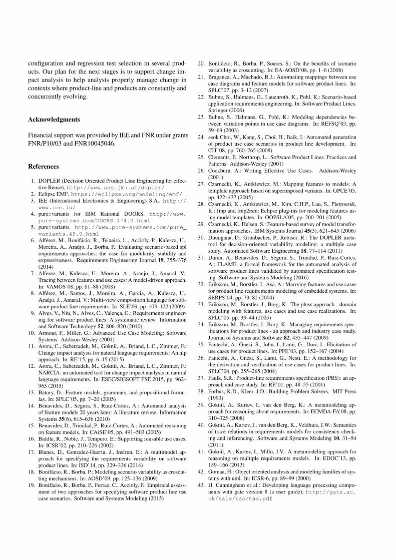
configuration and regression test selection in several prod-ucts. Our plan for the next stages is to support change im-pact analysis to help analysts properly manage change incontexts where product-line and products are constantly andconcurrently evolving.
Acknowledgments
Financial support was provided by IEE and FNR under grantsFNR/P10/03 and FNR10045046.
References
1. DOPLER (Decision Oriented Product Line Engineering for effec-tive Reuse), http://www.ase.jku.at/dopler/
2. Eclipse EMF, https://eclipse.org/modeling/emf/3. IEE (International Electronics & Engineering) S.A., http://
www.iee.lu/4. pure::variants for IBM Rational DOORS, http://www.
pure-systems.com/DOORS.174.0.html5. pure::variants, http://www.pure-systems.com/pure_
variants.49.0.html6. Alferez, M., Bonifacio, R., Teixeira, L., Accioly, P., Kulesza, U.,
Moreira, A., Araujo, J., Borba, P.: Evaluating scenario-based splrequirements approaches: the case for modularity, stability andexpressiveness. Requirements Engineering Journal 19, 355–376(2014)
7. Alferez, M., Kulesza, U., Moreira, A., Araujo, J., Amaral, V.:Tracing between features and use cases: A model-driven approach.In: VAMOS’08, pp. 81–88 (2008)
8. Alferez, M., Santos, J., Moreira, A., Garcia, A., Kulesza, U.,Araujo, J., Amaral, V.: Multi-view composition language for soft-ware product line requirements. In: SLE’09, pp. 103–122 (2009)
9. Alves, V., Niu, N., Alves, C., Valenca, G.: Requirements engineer-ing for software product lines: A systematic review. Informationand Software Technology 52, 806–820 (2010)
10. Armour, F., Miller, G.: Advanced Use Case Modeling: SoftwareSystems. Addison-Wesley (2001)
11. Arora, C., Sabetzadeh, M., Goknil, A., Briand, L.C., Zimmer, F.:Change impact analysis for natural language requirements: An nlpapproach. In: RE’15, pp. 6–15 (2015)
12. Arora, C., Sabetzadeh, M., Goknil, A., Briand, L.C., Zimmer, F.:NARCIA: an automated tool for change impact analysis in naturallanguage requirements. In: ESEC/SIGSOFT FSE 2015, pp. 962–965 (2015)
13. Batory, D.: Feature models, grammars, and propositional formu-las. In: SPLC’05, pp. 7–20 (2005)
14. Benavides, D., Segura, S., Ruiz-Cortes, A.: Automated analysisof feature models 20 years later: A literature review. InformationSystems 35(6), 615–636 (2010)
15. Benavides, D., Trinidad, P., Ruiz-Cortes, A.: Automated reasoningon feature models. In: CAiSE’05, pp. 491–503 (2005)
16. Biddle, R., Noble, J., Tempero, E.: Supporting reusable use cases.In: ICSR’02, pp. 210–226 (2002)
17. Blanes, D., Gonzalez-Huerta, J., Insfran, E.: A multimodel ap-proach for specifying the requirements variability on softwareproduct lines. In: ISD’14, pp. 329–336 (2014)
18. Bonifacio, R., Borba, P.: Modeling scenario variability as croscut-ting mechanisms. In: AOSD’09, pp. 125–136 (2009)
19. Bonifacio, R., Borba, P., Ferraz, C., Accioly, P.: Empirical assess-ment of two approaches for specifying software product line usecase scenarios. Software and Systems Modeling (2015)
20. Bonifacio, R., Borba, P., Soares, S.: On the benefits of scenariovariability as croscutting. In: EA-AOSD’08, pp. 1–6 (2008)
21. Braganca, A., Machado, R.J.: Automating mappings between usecase diagrams and feature models for software product lines. In:SPLC’07, pp. 3–12 (2007)
22. Buhne, S., Halmans, G., Lauenroth, K., Pohl, K.: Scenario-basedapplication requirements engineering. In: Software Product Lines.Springer (2006)
23. Buhne, S., Halmans, G., Pohl, K.: Modeling dependencies be-tween variation points in use case diagrams. In: REFSQ’03, pp.59–69 (2003)
24. seok Choi, W., Kang, S., Choi, H., Baik, J.: Automated generationof product use case scenarios in product line development. In:CIT’08, pp. 760–765 (2008)
25. Clements, P., Northrop, L.: Software Product Lines: Practices andPatterns. Addison-Wesley (2001)
26. Cockburn, A.: Writing Effective Use Cases. Addison-Wesley(2001)
27. Czarnecki, K., Antkiewicz, M.: Mapping features to models: Atemplate approach based on superimposed variants. In: GPCE’05,pp. 422–437 (2005)
28. Czarnecki, K., Antkiewicz, M., Kim, C.H.P., Lau, S., Pietroszek,K.: fmp and fmp2rsm: Eclipse plug-ins for modeling features us-ing model templates. In: OOPSLA’05, pp. 200–201 (2005)
29. Czarnecki, K., Helsen, S.: Feature-based survey of model transfor-mation approaches. IBM Systems Journal 45(3), 621–645 (2006)
30. Dhungana, D., Grunbacher, P., Rabiser, R.: The DOPLER meta-tool for decision-oriented variability modeling: a multiple casestudy. Automated Software Engineering 18, 77–114 (2011)
31. Duran, A., Benavides, D., Segura, S., Trinidad, P., Ruiz-Cortes,A.: FLAME: a formal framework for the automated analysis ofsoftware product lines validated by automated specification test-ing. Software and Systems Modeling (2016)
32. Eriksson, M., Borstler, J., Asa, A.: Marrying features and use casesfor product line requirements modeling of embedded systems. In:SERPS’04, pp. 73–82 (2004)
33. Eriksson, M., Borstler, J., Borg, K.: The pluss approach - domainmodeling with features, use cases and use case realizations. In:SPLC’05, pp. 33–44 (2005)
34. Eriksson, M., Borstler, J., Borg, K.: Managing requirements spec-ifications for product lines - an approach and industry case study.Journal of Systems and Software 82, 435–447 (2009)
35. Fantechi, A., Gnesi, S., John, I., Lami, G., Dorr, J.: Elicitation ofuse cases for product lines. In: PFE’03, pp. 152–167 (2004)
36. Fantechi, A., Gnesi, S., Lami, G., Nesti, E.: A methodology forthe derivation and verification of use cases for product lines. In:SPLC’04, pp. 255–265 (2004)
37. Faulk, S.R.: Product-line requirements specification (PRS): an ap-proach and case study. In: RE’01, pp. 48–55 (2001)
38. Forbus, K.D., Kleer, J.D.: Building Problem Solvers. MIT Press(1993)
39. Goknil, A., Kurtev, I., van den Berg, K.: A metamodeling ap-proach for reasoning about requirements. In: ECMDA-FA’08, pp.310–325 (2008)
40. Goknil, A., Kurtev, I., van den Berg, K., Veldhuis, J.W.: Semanticsof trace relations in requirements models for consistency check-ing and inferencing. Software and Systems Modeling 10, 31–54(2011)
41. Goknil, A., Kurtev, I., Millo, J.V.: A metamodeling approach forreasoning on multiple requirements models. In: EDOC’13, pp.159–166 (2013)
42. Gomaa, H.: Object oriented analysis and modeling families of sys-tems with uml. In: ICSR-6, pp. 89–99 (2000)
43. H. Cunningham et al.: Developing language processing compo-nents with gate version 8 (a user guide), http://gate.ac.uk/sale/tao/tao.pdf
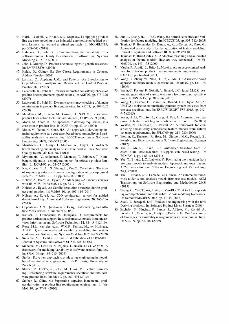
44. Hajri, I., Goknil, A., Briand, L.C., Stephany, T.: Applying productline use case modeling in an industrial automotive embedded sys-tem: Lessons learned and a refined approach. In: MODELS’15,pp. 338–347 (2015)
45. Halmans, G., Pohl, K.: Communicating the variability of asoftware-product family to customers. Software and SystemsModeling 2, 15–36 (2003)
46. John, I., Muthig, D.: Product line modeling with generic use cases.In: EMPRESS’04 (2004)
47. Kulak, D., Guiney, E.: Use Cases: Requirements in Context.Addison-Wesley (2003)
48. Larman, C.: Applying UML and Patterns: An Introduction toObject-Oriented Analysis and Design and the Unified Process.Prentice Hall (2002)
49. Lauenroth, K., Pohl, K.: Towards automated consistency checks ofproduct line requirements specifications. In: ASE’07, pp. 373–376(2007)
50. Lauenroth, K., Pohl, K.: Dynamic consistency checking of domainrequirements in product line engineering. In: RE’08, pp. 193–202(2008)
51. Mendonca, M., Branco, M., Cowan, D.: S.P.L.O.T. - softwareproduct lines online tools. In: 761-762 (ed.) OOPSLA’09 (2009)
52. Moon, M., Yeom, K.: An approach to develop requirement as acore asset in product line. In: ICSR’04, pp. 23–34 (2004)
53. Moon, M., Yeom, K., Chae, H.S.: An approach to developing do-main requirements as a core asset based on commonality and vari-ability analysis in a product line. IEEE Transactions on SoftwareEngineering 31(7), 551–569 (2005)
54. Mussbacher, G., Araujo, J., Moreira, A., Amyot, D.: AoURN-based modeling and analysis of software product lines. SoftwareQuality Journal 20, 645–687 (2012)
55. Myllarniemi, V., Asikainen, T., Mannisto, T., Soininen, T.: Kum-bang configurator - a configuration tool for software product fam-ilies. In: IJCAI-05, pp. 51–57 (2005)
56. Nie, K., Yue, T., Ali, S., Zhang, L., Fan, Z.: Constraints: The coreof supporting automated product configuration of cyber-physicalsystems. In: MODELS’13, pp. 370–387 (2013)
57. Nohrer, A., Biere, A., Egyed, A.: Managing SAT inconsistencieswith HUMUS. In: VaMoS’12, pp. 83–91 (2012)
58. Nohrer, A., Egyed, A.: Conflict resolution strategies during prod-uct configuration. In: VaMoS’10, pp. 107–114 (2010)
59. Nohrer, A., Egyed, A.: C2O configurator: a tool for guideddecision-making. Automated Software Engineering 20, 265–296(2013)
60. Oppenheim, A.N.: Questionnaire Design, Interviewing and Atti-tude Measurement. Continuum (2005)
61. Rabiser, R., Grunbacher, P., Dhungana, D.: Requirements forproduct derivation support: Results from a systematic literature re-view. Information and Software Technology 52, 324–346 (2010)
62. Rosa, M.L., van der Aalst, W.M.P., Dumas, M., ter Hofstede,A.H.M.: Questionnaire-based variability modeling for systemconfiguration. Software and Systems Modeling 8, 251–274 (2009)
63. Sinnema, M., Deelstra, S.: Industrial validation of COVAMOF.Journal of Systems and Software 81, 584–600 (2008)
64. Sinnema, M., Deelstra, S., Nijhuis, J., Bosch, J.: COVAMOF: Aframework for modeling variability in software product families.In: SPLC’04, pp. 197–213 (2004)
65. Stoiber, R.: A new approach to product line engineering in model-based requirements engineering. Ph.D. thesis, University ofZurich (2012)
66. Stoiber, R., Fricker, S., Jehle, M., Glinz, M.: Feature unweav-ing: Refactoring software requirements specifications into soft-ware product lines. In: RE’10, pp. 403–404 (2010)
67. Stoiber, R., Glinz, M.: Supporting stepwise, incremental prod-uct derivation in product line requirements engineering. In: Va-MoS’10, pp. 77–84 (2010)
68. Sun, J., Zhang, H., Li, Y.F., Wang, H.: Formal semantics and veri-fication for feature modeling. In: ICECCS’05, pp. 303–312 (2005)
69. Trinidad, P., Benavides, D., Duran, A., Ruiz-Cortes, A., Toro, M.:Automated error analysis for the agilization of feature modeling.Journal of Systems and Software 81, 883–896 (2008)
70. Trinidad, P., Ruiz-Cortes, A.: Abductive reasoning and automatedanalysis of feature models: How are they connected? In: Va-MoS’09, pp. 145–153 (2009)
71. Varela, P., Araujo, J., Brito, I., Moreira, A.: Aspect-oriented anal-ysis for software product lines requirements engineering. In:SAC’11, pp. 667–674 (2011)
72. Wang, B., Zhang, W., Zhao, H., Jin, Z., Mei, H.: A use case basedapproach to feature models’ construction. In: RE’09, pp. 121–130(2009)
73. Wang, C., Pastore, F., Goknil, A., Briand, L.C., Iqbal, M.Z.Z.: Au-tomatic generation of system test cases from use case specifica-tions. In: ISSTA’15, pp. 385–396 (2015)
74. Wang, C., Pastore, F., Goknil, A., Briand, L.C., Iqbal, M.Z.Z.:UMTG: a toolset to automatically generate system test cases fromuse case specifications. In: ESEC/SIGSOFT FSE 2015, pp. 942–945 (2015)
75. Wang, H., Li, Y.F., Sun, J., Zhang, H., Pan, J.: A semantic web ap-proach to feature modeling and verification. In: SWESE’05 (2005)
76. Weston, N., Chitchyan, R., Rashid, A.: A framework for con-structing semantically composable feature models from naturallanguage requirements. In: SPLC’09, pp. 211–220 (2009)
77. Wohlin, C., Runeson, P., Host, M., Ohlsson, M.C., Regnell, B.,Wesslen, A.: Experimentation in Software Engineering. Springer(2012)
78. Yue, T., Ali, S., Briand, L.C.: Automated transition from usecases to uml state machines to support state-based testing. In:ECMFA’11, pp. 115–131 (2011)
79. Yue, T., Briand, L.C., Labiche, Y.: Facilitating the transition fromuse case models to analysis models: Approach and experiments.ACM Transactions on Software Engineering and Methodology22(1) (2013)
80. Yue, T., Briand, L.C., Labiche, Y.: aToucan: An automated frame-work to derive uml analysis models from use case models. ACMTransactions on Software Engineering and Methodology 24(3)(2015)
81. Zhang, G., Yue, T., Wu, J., Ali, S.: Zen-RUCM: A tool for support-ing a comprehensive and extensible use case modeling framework.In: Demos@MoDELS 2013, pp. 41–45 (2013)
82. Ziadi, T., Jezequel, J.M.: Product line engineering with the uml:Deriving products. In: Software Product Lines. Springer (2006)
83. Zschaler, S., Sanchez, P., Santos, J., Alferez, M., Rashid, A.,Fuentes, L., Moreira, A., Araujo, J., Kulesza, U.: Vml* – a familyof languages for variability management in software product lines.In: SLE’09, pp. 82–102 (2009)