Configuring Wireshark - Cisco · Configuring Wireshark • FindingFeatureInformation,page1 •...
44
Configuring Wireshark • Finding Feature Information, on page 1 • Prerequisites for Wireshark, on page 1 • Restrictions for Wireshark, on page 1 • Information About Wireshark, on page 3 • How to Configure Wireshark, on page 12 • Monitoring Wireshark, on page 27 • Configuration Examples for Wireshark, on page 27 • Additional References, on page 43 • Feature History and Information for WireShark, on page 44 Finding Feature Information Your software release may not support all the features documented in this module. For the latest caveats and feature information, see Bug Search Tool and the release notes for your platform and software release. To find information about the features documented in this module, and to see a list of the releases in which each feature is supported, see the feature information table at the end of this module. Use Cisco Feature Navigator to find information about platform support and Cisco software image support. To access Cisco Feature Navigator, go to http://www.cisco.com/go/cfn. An account on Cisco.com is not required. Prerequisites for Wireshark • Wireshark is supported on Supervisor Engine 7-E, Supervisor Engine 7L-E, Catalyst 3850, Catalyst 3650, Wireless LAN Controller 5700 Series, Catalyst 4500X-16, and Catalyst 4500X-32. • IP Base image or IP Services image is required for Embedded Wireshark. Restrictions for Wireshark • Starting in Cisco IOS Release XE 3.3.0(SE), global packet capture on Wireshark is not supported. • Capture filters are not supported. Configuring Wireshark 1
-
Upload
truongkhue -
Category
Documents
-
view
240 -
download
1
Transcript of Configuring Wireshark - Cisco · Configuring Wireshark • FindingFeatureInformation,page1 •...

Configuring Wireshark
• Finding Feature Information, on page 1• Prerequisites for Wireshark, on page 1• Restrictions for Wireshark, on page 1• Information About Wireshark, on page 3• How to Configure Wireshark, on page 12• Monitoring Wireshark, on page 27• Configuration Examples for Wireshark, on page 27• Additional References, on page 43• Feature History and Information for WireShark, on page 44
Finding Feature InformationYour software release may not support all the features documented in this module. For the latest caveats andfeature information, see Bug Search Tool and the release notes for your platform and software release. Tofind information about the features documented in this module, and to see a list of the releases in which eachfeature is supported, see the feature information table at the end of this module.
Use Cisco Feature Navigator to find information about platform support and Cisco software image support.To access Cisco Feature Navigator, go to http://www.cisco.com/go/cfn. An account on Cisco.com is notrequired.
Prerequisites for Wireshark• Wireshark is supported on Supervisor Engine 7-E, Supervisor Engine 7L-E, Catalyst 3850, Catalyst 3650,Wireless LAN Controller 5700 Series, Catalyst 4500X-16, and Catalyst 4500X-32.
• IP Base image or IP Services image is required for Embedded Wireshark.
Restrictions for Wireshark• Starting in Cisco IOS Release XE 3.3.0(SE), global packet capture on Wireshark is not supported.
• Capture filters are not supported.
Configuring Wireshark1

• The CLI for configuringWireshark requires that the feature be executed only from EXECmode. Actionsthat usually occur in configuration submode (such as defining capture points), are handled at the EXECmode instead. All key commands are not NVGEN’d and are not synchronized to the standby supervisorin NSF and SSO scenarios.
• Packets captured in the output direction of an interface might not reflect the changes made by switchrewrite (includes TTL, VLAN tag, CoS, checksum, MAC addresses, DSCP, precedent, UP, etc.).
• Limiting circular file storage by file size is not supported.
• Embedded Wireshark is not supported on switches running LAN Base image.
Wireless Packet Capture
• The only form of wireless capture is a CAPWAP tunnel capture.
• When capturing CAPWAP tunnels, no other interface types can be used as attachment points on the samecapture point.
• Capturing multiple CAPWAP tunnels is supported.
• Core filters are not applied and should be omitted when capturing a CAPWAP tunnel.
• To capture a CAPWAP data tunnel, each CAPWAP tunnel is mapped to a physical port and an appropriateACL will be applied to filter the traffic.
• To capture a CAPWAP non-data tunnel, the switch is set to capture traffic on all ports and apply anappropriate ACL to filter the traffic.
• To capture a CAPWAP tunnel, no matter what kind, the controller will be told to capture the traffic onall physical ports and apply an appropriate ACL to filter the traffic.
Configuration Limitations
• Multiple capture points can be defined, but only one can be active at a time. You need to stop one beforeyou can start the other.
• Neither VRFs, management ports, nor private VLANs can be used as attachment points.
• Only one ACL of each type (IPv4, IPv6, MAC) is allowed in a Wireshark class map. There can be amaximum of three ACLs in a class map: one for IPv4, one for IPv6, and the other for MAC.
• Wireshark cannot capture packets on a destination SPAN port.
• Wireshark will stop capturing when one of the attachment points (interfaces) attached to a capture pointstops working. For example, if the device that is associated with an attachment point is unplugged fromthe switch. To resume capturing, the capture must be restarted manually.
• CPU-injected packets are considered control plane packets. Therefore, these types of packets will not becaptured on an interface egress capture.
• MAC ACL is only used for non-IP packets such as ARP. It will not be supported on a Layer 3 port orSVI.
• IPv6-based ACLs are not supported in VACL.
Configuring Wireshark2
Configuring WiresharkRestrictions for Wireshark

• Layer 2 and Layer 3 EtherChannels are not supported.
• ACL logging and Wireshark are incompatible. Once Wireshark is activated, it takes priority. All traffic,including that being captured by ACL logging on any ports, will be redirected to Wireshark. Werecommended that you deactivate ACL logging before starting Wireshark. Otherwise, Wireshark trafficwill be contaminated by ACL logging traffic.
• Wireshark does not capture packets dropped by floodblock.
• If you capture both PACL and RACL on the same port, only one copy is sent to the CPU. If you capturea DTLS-encrypted CAPWAP interface, two copies are sent to Wireshark, one encrypted and the otherdecrypted. The same behavior will occur if we capture a Layer 2 interface carrying DTLS-encryptedCAPWAP traffic. The core filter is based on the outer CAPWAP header.
Information About Wireshark
Wireshark OverviewWireshark is a packet analyzer program, formerly known as Ethereal, that supports multiple protocols andpresents information in a text-based user interface.
The ability to capture and analyze traffic provides data on network activity. Prior to Cisco IOS Release XE3.3.0(SE), only two features addressed this need: SPAN and debug platform packet. Both have limitations.SPAN is ideal for capturing packets, but can only deliver them by forwarding them to some specified localor remote destination; it provides no local display or analysis support. The debug platform packet commandis specific to the Catalyst 4500 series and only works on packets that come from the software process-forwardingpath. Also, the debug platform packet command has limited local display capabilities and no analysis support.
So the need exists for a traffic capture and analysis mechanism that is applicable to both hardware and softwareforwarded traffic and that provides strong packet capture, display, and analysis support, preferably using awell known interface.
Wireshark dumps packets to a file using a well known format called .pcap, and is applied or enabled onindividual interfaces. You specify an interface in EXEC mode along with the filter and other parameters. TheWireshark application is applied only when you enter a start command, and is removed only whenWiresharkstops capturing packets either automatically or manually.
Capture PointsA capture point is the central policy definition of the Wireshark feature. The capture point describes all of thecharacteristics associated with a given instance ofWireshark: which packets to capture, where to capture themfrom, what to do with the captured packets, and when to stop. Capture points can be modified after creation,and do not become active until explicitly activated with a start command. This process is termed activatingthe capture point or starting the capture point. Capture points are identified by name and can also be manuallyor automatically deactivated or stopped.
Multiple capture points can be defined, but only one can be active at a time. You need to stop one before youcan start the other.
Related TopicsDefining a Capture Point, on page 13
Configuring Wireshark3
Configuring WiresharkInformation About Wireshark

Adding or Modifying Capture Point Parameters, on page 18Deleting Capture Point Parameters, on page 20Deleting a Capture Point, on page 22Activating and Deactivating a Capture Point, on page 23Clearing the Capture Point Buffer, on page 25Example: Simple Capture and Display, on page 32Example: Simple Capture and Store, on page 33Example: Using Buffer Capture, on page 34Example: Capture Sessions, on page 39Example: Capture and Store in Lock-step Mode, on page 40Example: Simple Capture and Store of Packets in Egress Direction, on page 41
Attachment PointsAn attachment point is a point in the logical packet process path associated with a capture point. An attachmentpoint is an attribute of the capture point. Packets that impact an attachment point are tested against capturepoint filters; packets that match are copied and sent to the associated Wireshark instance of the capture point.A specific capture point can be associated with multiple attachment points, with limits on mixing attachmentpoints of different types. Some restrictions apply when you specify attachment points of different types.Attachment points are directional (input or output or both) with the exception of the Layer 2 VLAN attachmentpoint, which is always bidirectional.
Related TopicsDefining a Capture Point, on page 13Adding or Modifying Capture Point Parameters, on page 18Deleting Capture Point Parameters, on page 20Deleting a Capture Point, on page 22Activating and Deactivating a Capture Point, on page 23Clearing the Capture Point Buffer, on page 25Example: Simple Capture and Display, on page 32Example: Simple Capture and Store, on page 33Example: Using Buffer Capture, on page 34Example: Capture Sessions, on page 39Example: Capture and Store in Lock-step Mode, on page 40Example: Simple Capture and Store of Packets in Egress Direction, on page 41
FiltersFilters are attributes of a capture point that identify and limit the subset of traffic traveling through theattachment point of a capture point, which is copied and passed to Wireshark. To be displayed by Wireshark,a packet must pass through an attachment point, as well as all of the filters associated with the capture point.
A capture point has the following types of filters:
• Core system filter—The core system filter is applied by hardware, and its match criteria is limited byhardware. This filter determines whether hardware-forwarded traffic is copied to software for Wiresharkpurposes.
Configuring Wireshark4
Configuring WiresharkAttachment Points

• Display filter—The display filter is applied by Wireshark. Packets that fail the display filter are notdisplayed.
Core System Filter
You can specify core system filter match criteria by using the class map or ACL, or explicitly by using theCLI.
When specifying CAPWAP as an attachment point, the core system filter is not used.Note
In some installations, you need to obtain authorization to modify the switch configuration, which can lead toextended delays if the approval process is lengthy. This can limit the ability of network administrators tomonitor and analyze traffic. To address this situation,Wireshark supports explicit specification of core systemfilter match criteria from the EXECmode CLI. The disadvantage is that the match criteria that you can specifyis a limited subset of what class map supports, such as MAC, IP source and destination addresses, ether-type,IP protocol, and TCP/UDP source and destination ports.
If you prefer to use configuration mode, you can define ACLs or have class maps refer capture points to them.Explicit and ACL-based match criteria are used internally to construct class maps and policy maps.
Note The ACL and class map configuration are part of the system and not aspects of the Wireshark feature.
Display Filter
With the display filter, you can direct Wireshark to further narrow the set of packets to display when decodingand displaying from a .pcap file.
Related TopicsAdditional References, on page 43
ActionsWireshark can be invoked on live traffic or on a previously existing .pcap file. When invoked on live traffic,it can perform four types of actions on packets that pass its display filters:
• Captures to buffer in memory to decode and analyze and store
• Stores to a .pcap file
• Decodes and displays
• Stores and displays
When invoked on a .pcap file only, only the decode and display action is applicable.
Storage of Captured Packets to Buffer in MemoryPackets can be stored in the capture buffer in memory for subsequent decode, analysis, or storage to a .pcapfile.
The capture buffer can be in linear or circular mode. In linear mode, new packets are discarded when thebuffer is full. In circular mode, if the buffer is full, the oldest packets are discarded to accommodate the new
Configuring Wireshark5
Configuring WiresharkActions

packets. Although the buffer can also be cleared when needed, this mode is mainly used for debugging networktraffic.
If you have more than one capture that is storing packets in a buffer, clear the buffer before starting a newcapture to avoid memory loss.
Note
Storage of Captured Packets to a .pcap File
When WireShark is used on switches in a stack, packet captures can be stored only on flash or USB flashdevices connected to the active switch.
For example, if flash1 is connected to the active switch, and flash2 is connected to the secondary switch, onlyflash1 can be used to store packet captures.
Attempts to store packet captures on devices other than flash or USB flash devices connected to the activeswitch will probably result in errors.
Note
Wireshark can store captured packets to a .pcap file. The capture file can be located on the following storagedevices:
• Switch on-board flash storage (flash:)
• USB drive (usbflash0:)
Attempts to store packet captures on unsupported devices or devices not connected to the active switch willprobably result in errors.
Note
When configuring aWireshark capture point, you can associate a filename.When the capture point is activated,Wireshark creates a file with the specified name and writes packets to it. If the file already exists when thefile is associated or the capture point is activated, Wireshark queries you as to whether the file can beoverwritten. Only one capture point may be associated with a given filename.
If the destination of the Wireshark writing process is full, Wireshark fails with partial data in the file. Youmust ensure that there is sufficient space in the file system before you start the capture session. With CiscoIOS Release IOS XE 3.3.0(SE), the file system full status is not detected for some storage devices.
You can reduce the required storage space by retaining only a segment, instead of the entire packet. Typically,you do not require details beyond the first 64 or 128 bytes. The default behavior is to store the entire packet.
To avoid possible packet drops when processing and writing to the file system, Wireshark can optionally usea memory buffer to temporarily hold packets as they arrive. Memory buffer size can be specified when thecapture point is associated with a .pcap file.
Configuring Wireshark6
Configuring WiresharkStorage of Captured Packets to a .pcap File

Packet Decoding and DisplayWireshark can decode and display packets to the console. This functionality is possible for capture pointsapplied to live traffic and for capture points applied to a previously existing .pcap file.
Decoding and displaying packets may be CPU intensive.Note
Wireshark can decode and display packet details for a wide variety of packet formats. The details are displayedby entering themonitor capture name start command with one of the following keyword options, whichplace you into a display and decode mode:
• brief—Displays one line per packet (the default).
• detailed—Decodes and displays all the fields of all the packets whose protocols are supported. Detailedmodes require more CPU than the other two modes.
• (hexadecimal) dump—Displays one line per packet as a hexadecimal dump of the packet data and theprintable characters of each packet.
When you enter the capture command with the decode and display option, the Wireshark output is returnedto Cisco IOS and displayed on the console unchanged.
Live Traffic Display
Wireshark receives copies of packets from the core system. Wireshark applies its display filters to discarduninteresting packets, and then decodes and displays the remaining packets.
.pcap File Display
Wireshark can decode and display packets from a previously stored .pcap file and direct the display filter toselectively displayed packets.
Packet Storage and DisplayFunctionally, this mode is a combination of the previous two modes. Wireshark stores packets in the specified.pcap file and decodes and displays them to the console. Only the core filters are applicable here.
Wireshark Capture Point Activation and DeactivationAfter aWireshark capture point has been defined with its attachment points, filters, actions, and other options,it must be activated. Until the capture point is activated, it does not actually capture packets.
Before a capture point is activated, some functional checks are performed. A capture point cannot be activatedif it has neither a core system filter nor attachment points defined. Attempting to activate a capture point thatdoes not meet these requirements generates an error.*
*When performing a wireless capture with a CAPWAP tunneling interface, the core system filter is not requiredand cannot be used.
Note
Configuring Wireshark7
Configuring WiresharkPacket Decoding and Display

The display filters are specified as needed.
After Wireshark capture points are activated, they can be deactivated in multiple ways. A capture point thatis storing only packets to a .pcap file can be halted manually or configured with time or packet limits, afterwhich the capture point halts automatically.
When a Wireshark capture point is activated, a fixed rate policer is applied automatically in the hardware sothat the CPU is not flooded with Wireshark-directed packets. The disadvantage of the rate policer is that youcannot capture contiguous packets beyond the established rate even if more resources are available.
Wireshark FeaturesThis section describes how Wireshark features function in the switch environment:
• If port security andWireshark are applied on an ingress capture, a packet that is dropped by port securitywill still be captured by Wireshark. If port security is applied on an ingress capture, and Wireshark isapplied on an egress capture, a packet that is dropped by port security will not be captured byWireshark.
• Packets dropped by Dynamic ARP Inspection (DAI) are not captured by Wireshark.
• If a port that is in STP blocked state is used as an attachment point and the core filter is matched,Wiresharkwill capture the packets that come into the port, even though the packets will be dropped by the switch.
• Classification-based security features—Packets that are dropped by input classification-based securityfeatures (such as ACLs and IPSG) are not caught by Wireshark capture points that are connected toattachment points at the same layer. In contrast, packets that are dropped by output classification-basedsecurity features are caught by Wireshark capture points that are connected to attachment points at thesame layer. The logical model is that the Wireshark attachment point occurs after the security featurelookup on the input side, and symmetrically before the security feature lookup on the output side.
On ingress, a packet goes through a Layer 2 port, a VLAN, and a Layer 3 port/SVI. On egress, the packetgoes through a Layer 3 port/SVI, a VLAN, and a Layer 2 port. If the attachment point is before the pointwhere the packet is dropped, Wireshark will capture the packet. Otherwise, Wireshark will not capturethe packet. For example, Wireshark capture policies connected to Layer 2 attachment points in the inputdirection capture packets dropped by Layer 3 classification-based security features. Symmetrically,Wireshark capture policies attached to Layer 3 attachment points in the output direction capture packetsdropped by Layer 2 classification-based security features.
• Routed ports and switch virtual interfaces (SVIs)—Wireshark cannot capture the output of an SVI becausethe packets that go out of an SVI's output are generated by CPU. To capture these packets, include thecontrol plane as an attachment point.
• VLANs—When a VLAN is used as a Wireshark attachment point, packets are captured in the inputdirection only.
• Redirection features—In the input direction, features traffic redirected by Layer 3 (such as PBR andWCCP) are logically later than Layer 3 Wireshark attachment points. Wireshark captures these packetseven though they might later be redirected out another Layer 3 interface. Symmetrically, output featuresredirected by Layer 3 (such as egress WCCP) are logically prior to Layer 3Wireshark attachment points,and Wireshark will not capture them.
• SPAN—Wireshark cannot capture packets on interface configured as a SPAN source or destination.
• You can capture packets from a maximum of 1000 VLANs at a time, if no ACLs are applied. If ACLsare applied, the hardware will have less space for Wireshark to use. As a result, the maximum numberof VLANs than can be used for packet capture at a time will be lower. Using more than 1000 VLANs
Configuring Wireshark8
Configuring WiresharkWireshark Features

tunnels at a time or extensive ACLs might have unpredictable results. For example, mobility may godown.
Capturing an excessive number of attachment points at the same time is stronglydiscouraged because it may cause excessive CPU utilization and unpredictablehardware behavior.
Note
Wireless Packet Capture in Wireshark
• Wireless traffic is encapsulated inside CAPWAP packets. However, capturing only a particular wirelessclient's traffic inside a CAPWAP tunnel is not supported when using the CAPWAP tunnel as an attachmentpoint. To capture only a particular wireless client's traffic, use the client VLAN as an attachment pointand formulate the core filter accordingly.
• Limited decoding of inner wireless traffic is supported. Decoding of inner wireless packets inside encryptedCAPWAP tunnels is not supported.
• No other interface type can be used with the CAPWAP tunneling interface on the same capture point. ACAPWAP tunneling interface and a Level 2 port cannot be attachment points on the same capture point.
• You cannot specify a core filter when capturing packets forWireshark via the CAPWAP tunnel. However,you can use the Wireshark display filters for filtering wireless client traffic against a specific wirelessclient.
• You can capture packets from a maximum of 135 CAPWAP tunnels at a time if no ACLs are applied.If ACLs are applied, the hardware memory will have less space for Wireshark to use. As a result, themaximum number of CAPWAP tunnels than can be used for packet capture at a time will be lower.Using more than 135 CAPWAP tunnels at a time or unsing extensive ACLs might have unpredictableresults. For example, mobility may go down.
Capturing an excessive number of attachment points at the same time is stronglydiscouraged because it may cause excessive CPU utilization and unpredictablehardware behavior.
Note
Guidelines for Wireshark• During Wireshark packet capture, hardware forwarding happens concurrently.
• Before starting a Wireshark capture process, ensure that CPU usage is moderate and that sufficientmemory (at least 200 MB) is available.
• If you plan to store packets to a storage file, ensure that sufficient space is available before beginning aWireshark capture process.
• The CPU usage during Wireshark capture depends on how many packets match the specified conditionsand on the intended actions for the matched packets (store, decode and display, or both).
Configuring Wireshark9
Configuring WiresharkGuidelines for Wireshark

• Where possible, keep the capture to the minimum (limit by packets, duration) to avoid high CPU usageand other undesirable conditions.
• Because packet forwarding typically occurs in hardware, packets are not copied to the CPU for softwareprocessing. For Wireshark packet capture, packets are copied and delivered to the CPU, which causesan increase in CPU usage.
To avoid high CPU usage, do the following:
• Attach only relevant ports.
• Use a class map, and secondarily, an access list to express match conditions. If neither is viable,use an explicit, in-line filter.
• Adhere closely to the filter rules. Restrict the traffic type (such as, IPv4 only) with a restrictive,rather than relaxed ACL, which elicits unwanted traffic.
• Always limit packet capture to either a shorter duration or a smaller packet number. The parameters ofthe capture command enable you to specify the following:
• Capture duration
• Number of packets captured
• File size
• Packet segment size
• Run a capture session without limits if you know that very little traffic matches the core filter.
• You might experience high CPU (or memory) usage if:
• You leave a capture session enabled and unattended for a long period of time, resulting inunanticipated bursts of traffic.
• You launch a capture session with ring files or capture buffer and leave it unattended for a longtime, resulting in performance or system health issues.
• During a capture session, watch for high CPU usage and memory consumption due to Wireshark thatmay impact switch performance or health. If these situations arise, stop theWireshark session immediately.
• Avoid decoding and displaying packets from a .pcap file for a large file. Instead, transfer the .pcap fileto a PC and run Wireshark on the PC.
• You can define up to eight Wireshark instances. An active show command that decodes and displayspackets from a .pcap file or capture buffer counts as one instance. However, only one of the instancescan be active.
• Whenever an ACL that is associated with a running capture is modified, you must restart the capture forthe ACL modifications to take effect. If you do not restart the capture, it will continue to use the originalACL as if it had not been modified.
• To avoid packet loss, consider the following:
• Use store-only (when you do not specify the display option) while capturing live packets rather thandecode and display, which is an CPU-intensive operation (especially in detailed mode).
Configuring Wireshark10
Configuring WiresharkGuidelines for Wireshark

• If you have more than one capture that is storing packets in a buffer, clear the buffer before startinga new capture to avoid memory loss.
• If you use the default buffer size and see that you are losing packets, you can increase the buffersize to avoid losing packets.
• Writing to flash disk is a CPU-intensive operation, so if the capture rate is insufficient, you maywant to use a buffer capture.
• TheWireshark capture session operates normally in streamingmode where packets are both capturedand processed. However, when you specify a buffer size of at least 32MB, the session automaticallyturns on lock-step mode in which a Wireshark capture session is split into two phases: capture andprocess. In the capture phase, the packets are stored in the temporary buffer. The duration parameterin lock-step mode serves as capture duration rather than session duration. When the buffer is fullor the capture duration or packet limit has been attained, a session transitions to the process phase,wherein it stops accepting packets and starts processing packets in the buffer. You can also stop thecapture manually. You will see a message in the output when the capture stops. With this secondapproach (lock-step mode), a higher capture throughput can be achieved.
If you are capturing packets to a buffer, there is no file storage defined. Hence,you must export your capture from the buffer to a static storage file. Use themonitor capture capture-name export file-location : file-name command.
Note
• The streaming capture mode supports approximately 1000 pps; lock-step mode supportsapproximately 2 Mbps (measured with 256-byte packets). When the matching traffic rate exceedsthis number, you may experience packet loss.
• If you want to decode and display live packets in the console window, ensure that the Wireshark sessionis bounded by a short capture duration.
Warning: A Wireshark session with either a longer duration limit or no capture duration (using a terminalwith no auto-more support using the term len 0 command) may make the console or terminal unusable.
Note
• When using Wireshark to capture live traffic that leads to high CPU, usage, consider applying a QoSpolicy temporarily to limit the actual traffic until the capture process concludes.
• All Wireshark-related commands are in EXEC mode; no configuration commands exist for Wireshark.
If you need to use access list or class-map in the Wireshark CLI, you must define an access list and classmap with configuration commands.
• No specific order applies when defining a capture point; you can define capture point parameters in anyorder, provided that CLI allows this. The Wireshark CLI allows as many parameters as possible on asingle line. This limits the number of commands required to define a capture point.
• All parameters except attachment points take a single value. Generally, you can replace the value witha new one by reentering the command. After user confirmation, the system accepts the new value andoverrides the older one. A no form of the command is unnecessary to provide a new value, but it isnecessary to remove a parameter.
Configuring Wireshark11
Configuring WiresharkGuidelines for Wireshark
• Wireshark allows you to specify one or more attachment points. To add more than one attachment point,reenter the command with the new attachment point. To remove an attachment point, use the no formof the command. You can specify an interface range as an attachment point. For example, entermonitorcapturemycap interfaceGigabitEthernet1/0/1 inwhere interface GigabitEthernet1/0/1 is an attachmentpoint.
If you also need to attach interface GigabitEthernet1/0/2, specify it in another line as follows:
monitor capture mycap interface GigabitEthernet1/0/2 in
• You can modify any of the parameters of a capture point while a session is active, but you must restartthe session for the modifications to take effect.
• The action you want to perform determines which parameters are mandatory. The Wireshark CLI allowsyou to specify or modify any parameter prior to entering the start command. When you enter the startcommand,Wireshark will start only after determining that all mandatory parameters have been provided.
• If the capture file already exists, it provides a warning and receives confirmation before proceeding. Thisprevents you from mistakenly overwriting a file.
• The core filter can be an explicit filter, access list, or class map. Specifying a newer filter of these typesreplaces the existing one.
A core filter is required except when using a CAPWAP tunnel interface as acapture point attachment point.
Note
• You can terminate a Wireshark session with an explicit stop command or by entering q in automoremode. The session could terminate itself automatically when a stop condition such as duration or packetcapture limit is met.
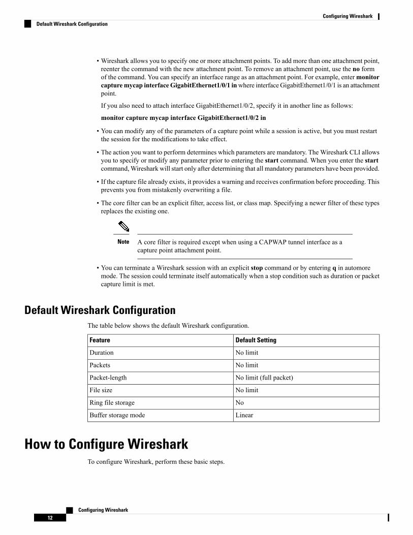
Default Wireshark ConfigurationThe table below shows the default Wireshark configuration.
Default SettingFeature
No limitDuration
No limitPackets
No limit (full packet)Packet-length
No limitFile size
NoRing file storage
LinearBuffer storage mode
How to Configure WiresharkTo configure Wireshark, perform these basic steps.
Configuring Wireshark12
Configuring WiresharkDefault Wireshark Configuration

1. Define a capture point.
2. (Optional) Add or modify the capture point's parameters.
3. Activate or deactivate a capture point.
4. Delete the capture point when you are no longer using it.
Related TopicsDefining a Capture Point, on page 13Adding or Modifying Capture Point Parameters, on page 18Deleting Capture Point Parameters, on page 20Deleting a Capture Point, on page 22Activating and Deactivating a Capture Point, on page 23Clearing the Capture Point Buffer, on page 25Example: Simple Capture and Display, on page 32Example: Simple Capture and Store, on page 33Example: Using Buffer Capture, on page 34Example: Capture Sessions, on page 39Example: Capture and Store in Lock-step Mode, on page 40Example: Simple Capture and Store of Packets in Egress Direction, on page 41
Defining a Capture PointThe example in this procedure defines a very simple capture point. If you choose, you can define a capturepoint and all of its parameters with one instance of themonitor capture command.
You must define an attachment point, direction of capture, and core filter to have a functional capture point.
An exception to needing to define a core filter is when you are defining a wireless capture point using aCAPWAP tunneling interface. In this case, you do not define your core filter. It cannot be used.
Note
Follow these steps to define a capture point.
SUMMARY STEPS
1. enable2. show capwap summary3. monitor capture {capture-name}{interface interface-type interface-id | control-plane}{in |
out | both}4. monitor capture {capture-name}[match {any | ipv4 any any | ipv6} any any}]5. show monitor capture {capture-name}[ parameter]6. show running-config7. copy running-config startup-config
Configuring Wireshark13
Configuring WiresharkDefining a Capture Point

DETAILED STEPS
PurposeCommand or Action
Enables privileged EXEC mode. Enter your password ifprompted.
enable
Example:
Step 1
Switch> enable
Displays the CAPWAP tunnels available as attachmentpoints for a wireless capture.
show capwap summary
Example:
Step 2
Use this command only if you are using aCAPWAP tunnel as an attachment point toperform a wireless capture. See the CAPWAPexample in the examples section.
NoteSwitch# show capwap summary
Defines the capture point, specifies the attachment pointwith which the capture point is associated, and specifies thedirection of the capture.
monitor capture {capture-name}{interfaceinterface-type interface-id | control-plane}{in | out| both}
Step 3
Example: The keywords have these meanings:Switch# monitor capture mycap interfaceGigabitEthernet1/0/1 in
• capture-name—Specifies the name of the capture pointto be defined (mycap is used in the example).
• (Optional) interface interface-typeinterface-id—Specifies the attachment point withwhich the capture point is associated(GigabitEthernet1/0/1 is used in the example).
Optionally, you can define multipleattachment points and all of the parametersfor this capture point with this onecommand instance. These parameters arediscussed in the instructions for modifyingcapture point parameters. Range support isalso available both for adding and removingattachment points.
Note
Use one of the following for interface-type:
• GigabitEthernet—Specifies the attachment pointas GigabitEthernet.
• vlan—Specifies the attachment point as a VLAN.
Only ingress capture (in) is allowedwhen using this interface as anattachment point.
Note
• capwap—Specifies the attachment point as aCAPWAP tunnel.
Configuring Wireshark14
Configuring WiresharkDefining a Capture Point

PurposeCommand or Action
When using this interface as anattachment point, a core filter cannotbe used.
Note
• (Optional) control-plane—Specifies the control planeas an attachment point.
• in | out | both—Specifies the direction of capture.
Defines the core system filter.monitor capture {capture-name}[match {any | ipv4any any | ipv6} any any}]
Step 4
When using the CAPWAP tunneling interfaceas an attachment point, do not perform this stepbecause a core filter cannot be used.
NoteExample:Switch# monitor capture mycap interfaceGigabitEthernet1/0/1 in match any
The keywords have these meanings:
• capture-name—Specifies the name of the capture pointto be defined (mycap is used in the example).
• match—Specifies a filter. The first filter defined isthe core filter.
A capture point cannot be activated if it hasneither a core system filter nor attachmentpoints defined. Attempting to activate acapture point that does not meet theserequirements generates an error.
Note
• ipv4—Specifies an IP version 4 filter.
• ipv6—Specifies an IP version 6 filter.
Displays the capture point parameters that you defined inStep 2 and confirms that you defined a capture point.
show monitor capture {capture-name}[ parameter]
Example:
Step 5
Switch# show monitor capture mycap parametermonitor capture mycap interface
GigabitEthernet1/0/1 inmonitor capture mycap match any
Verifies your entries.show running-config
Example:
Step 6
Switch# show running-config
(Optional) Saves your entries in the configuration file.copy running-config startup-config
Example:
Step 7
Switch# copy running-config startup-config
Configuring Wireshark15
Configuring WiresharkDefining a Capture Point

Example
To define a capture point with a CAPWAP attachment point:Switch# show capwap summary
CAPWAP Tunnels General Statistics:Number of Capwap Data Tunnels = 1Number of Capwap Mobility Tunnels = 0Number of Capwap Multicast Tunnels = 0
Name APName Type PhyPortIf Mode McastIf------ -------------------------------- ---- --------- --------- -------Ca0 AP442b.03a9.6715 data Gi3/0/6 unicast -
Name SrcIP SrcPort DestIP DstPort DtlsEn MTU Xact------ --------------- ------- --------------- ------- ------ ----- ----Ca0 10.10.14.32 5247 10.10.14.2 38514 No 1449 0
Switch# monitor capture mycap interface capwap 0 bothSwitch# monitor capture mycap file location flash:mycap.pcapSwitch# monitor capture mycap file buffer-size 1Switch# monitor capture mycap start
*Aug 20 11:02:21.983: %BUFCAP-6-ENABLE: Capture Point mycap enabled.on
Switch# show monitor capture mycap parametermonitor capture mycap interface capwap 0 inmonitor capture mycap interface capwap 0 outmonitor capture mycap file location flash:mycap.pcap buffer-size 1
Switch#Switch# show monitor capture mycap
Status Information for Capture mycapTarget Type:Interface: CAPWAP,Ingress:
0Egress:
0Status : ActiveFilter Details:Capture all packets
Buffer Details:Buffer Type: LINEAR (default)File Details:Associated file name: flash:mycap.pcapSize of buffer(in MB): 1Limit Details:Number of Packets to capture: 0 (no limit)Packet Capture duration: 0 (no limit)Packet Size to capture: 0 (no limit)Packets per second: 0 (no limit)Packet sampling rate: 0 (no sampling)
Switch#Switch# show monitor capture file flash:mycap.pcap1 0.000000 00:00:00:00:00:00 -> 3c:ce:73:39:c6:60 IEEE 802.11 Probe Request, SN=0, FN=0,Flags=........2 0.499974 00:00:00:00:00:00 -> 3c:ce:73:39:c6:60 IEEE 802.11 Probe Request, SN=0, FN=0,Flags=........3 2.000000 00:00:00:00:00:00 -> 3c:ce:73:39:c6:60 IEEE 802.11 Probe Request, SN=0, FN=0,
Configuring Wireshark16
Configuring WiresharkDefining a Capture Point

Flags=........4 2.499974 00:00:00:00:00:00 -> 3c:ce:73:39:c6:60 IEEE 802.11 Probe Request, SN=0, FN=0,Flags=........5 3.000000 00:00:00:00:00:00 -> 3c:ce:73:39:c6:60 IEEE 802.11 Probe Request, SN=0, FN=0,Flags=........6 4.000000 00:00:00:00:00:00 -> 3c:ce:73:39:c6:60 IEEE 802.11 Probe Request, SN=0, FN=0,Flags=........7 4.499974 00:00:00:00:00:00 -> 3c:ce:73:39:c6:60 IEEE 802.11 Probe Request, SN=0, FN=0,Flags=........8 5.000000 00:00:00:00:00:00 -> 3c:ce:73:39:c6:60 IEEE 802.11 Probe Request, SN=0, FN=0,Flags=........9 5.499974 00:00:00:00:00:00 -> 3c:ce:73:39:c6:60 IEEE 802.11 Probe Request, SN=0, FN=0,Flags=........10 6.000000 00:00:00:00:00:00 -> 3c:ce:73:39:c6:60 IEEE 802.11 Probe Request, SN=0, FN=0,Flags=........11 8.000000 00:00:00:00:00:00 -> 3c:ce:73:39:c6:60 IEEE 802.11 Probe Request, SN=0, FN=0,Flags=........12 9.225986 10.10.14.2 -> 10.10.14.32 DTLSv1.0 Application Data13 9.225986 10.10.14.2 -> 10.10.14.32 DTLSv1.0 Application Data14 9.225986 10.10.14.2 -> 10.10.14.32 DTLSv1.0 Application Data15 9.231998 10.10.14.2 -> 10.10.14.32 DTLSv1.0 Application Data16 9.231998 10.10.14.2 -> 10.10.14.32 DTLSv1.0 Application Data17 9.231998 10.10.14.2 -> 10.10.14.32 DTLSv1.0 Application Data18 9.236987 10.10.14.2 -> 10.10.14.32 DTLSv1.0 Application Data19 10.000000 00:00:00:00:00:00 -> 3c:ce:73:39:c6:60 IEEE 802.11 Probe Request, SN=0, FN=0,Flags=........20 10.499974 00:00:00:00:00:00 -> 3c:ce:73:39:c6:60 IEEE 802.11 Probe Request, SN=0, FN=0,Flags=........21 12.000000 00:00:00:00:00:00 -> 3c:ce:73:39:c6:60 IEEE 802.11 Probe Request, SN=0, FN=0,Flags=........22 12.239993 10.10.14.2 -> 10.10.14.32 DTLSv1.0 Application Data23 12.244997 10.10.14.2 -> 10.10.14.32 DTLSv1.0 Application Data24 12.244997 10.10.14.2 -> 10.10.14.32 DTLSv1.0 Application Data25 12.250994 10.10.14.2 -> 10.10.14.32 DTLSv1.0 Application Data26 12.256990 10.10.14.2 -> 10.10.14.32 DTLSv1.0 Application Data27 12.262987 10.10.14.2 -> 10.10.14.32 DTLSv1.0 Application Data28 12.499974 00:00:00:00:00:00 -> 3c:ce:73:39:c6:60 IEEE 802.11 Probe Request, SN=0, FN=0,Flags=........29 12.802012 10.10.14.3 -> 10.10.14.255 NBNS Name query NB WPAD.<00>30 13.000000 00:00:00:00:00:00 -> 3c:ce:73:39:c6:60 IEEE 802.11 Probe Request, SN=0, FN=0,Flags=........
What to do next
You can add additional attachment points, modify the parameters of your capture point, then activate it, or ifyou want to use your capture point just as it is, you can now activate it.
You cannot change a capture point's parameters using the methods presented in this topic.Note
Related TopicsHow to Configure Wireshark, on page 12Capture Points, on page 3Attachment Points, on page 4Example: Simple Capture and Display, on page 32Example: Simple Capture and Store, on page 33Example: Using Buffer Capture, on page 34
Configuring Wireshark17
Configuring WiresharkDefining a Capture Point

Example: Capture Sessions, on page 39Example: Capture and Store in Lock-step Mode, on page 40Example: Simple Capture and Store of Packets in Egress Direction, on page 41
Adding or Modifying Capture Point ParametersAlthough listed in sequence, the steps to specify values for the parameters can be executed in any order. Youcan also specify them in one, two, or several lines. Except for attachment points, which can be multiple, youcan replace any value with a more recent value by redefining the same option.
Follow these steps to modify a capture point's parameters.
Before you begin
A capture point must be defined before you can use these instructions.
SUMMARY STEPS
1. enable2. monitor capture {capture-name} match {any | mac mac-match-string | ipv4 {any | host
| protocol}{any | host} | ipv6 {any | host | protocol}{any | host}}3. monitor capture {capture-name} limit {[duration seconds][packet-length size][packets
num]}4. monitor capture {capture-name} file {location filename}5. monitor capture {capture-name} file {buffer-size size}6. show monitor capture {capture-name}[ parameter]7. end8. show running-config9. copy running-config startup-config
DETAILED STEPS
PurposeCommand or Action
Enables privileged EXEC mode. Enter your password ifprompted.
enable
Example:
Step 1
Switch> enable
Defines the core system filter (ipv4 any any), defined eitherexplicitly, through ACL or through a class map.
monitor capture {capture-name} match {any | macmac-match-string | ipv4 {any | host |
Step 2
protocol}{any | host} | ipv6 {any | host |protocol}{any | host}}
If you are defining a wireless capture point usinga CAPWAP tunneling interface, this commandwill have no effect, so it should not be used.
Note
Example:Switch# monitor capture mycap match ipv4 any any
Configuring Wireshark18
Configuring WiresharkAdding or Modifying Capture Point Parameters

PurposeCommand or Action
Specifies the session limit in seconds (60), packets captured,or the packet segment length to be retained by Wireshark(400).
monitor capture {capture-name} limit {[durationseconds][packet-length size][packets num]}
Example:
Step 3
Switch# monitor capture mycap limit duration 60packet-len 400
Specifies the file association, if the capture point intends tocapture packets rather than only display them.
monitor capture {capture-name} file {locationfilename}
Example:
Step 4
Switch# monitor capture mycap file locationflash:mycap.pcap
Specifies the size of the memory buffer used by Wiresharkto handle traffic bursts.
monitor capture {capture-name} file {buffer-sizesize}
Example:
Step 5
Switch# monitor capture mycap file buffer-size 100
Displays the capture point parameters that you definedpreviously.
show monitor capture {capture-name}[ parameter]
Example:
Step 6
Switch# show monitor capture mycap parametermonitor capture mycap interface
GigabitEthernet1/0/1 inmonitor capture mycap match ipv4 any anymonitor capture mycap limit duration 60
packet-len 400monitor capture point mycap file location
bootdisk:mycap.pcapmonitor capture mycap file buffer-size 100
Returns to privileged EXEC mode.end
Example:
Step 7
Switch(config)# end
Verifies your entries.show running-config
Example:
Step 8
Switch# show running-config
(Optional) Saves your entries in the configuration file.copy running-config startup-config
Example:
Step 9
Switch# copy running-config startup-config
Configuring Wireshark19
Configuring WiresharkAdding or Modifying Capture Point Parameters

Examples
Modifying Parameters
Associating or Disassociating a Capture FileSwitch# monitor capture point mycap file location flash:mycap.pcapSwitch# no monitor capture mycap file
Specifying a Memory Buffer Size for Packet Burst HandlingSwitch# monitor capture mycap buffer size 100
Defining an Explicit Core System Filter to Match Both IPv4 and IPv6Switch# monitor capture mycap match any
What to do next
if your capture point contains all of the parameters you want, activate it.
Related TopicsHow to Configure Wireshark, on page 12Capture Points, on page 3Attachment Points, on page 4Example: Simple Capture and Display, on page 32Example: Simple Capture and Store, on page 33Example: Using Buffer Capture, on page 34Example: Capture Sessions, on page 39Example: Capture and Store in Lock-step Mode, on page 40Example: Simple Capture and Store of Packets in Egress Direction, on page 41
Deleting Capture Point ParametersAlthough listed in sequence, the steps to delete parameters can be executed in any order. You can also deletethem in one, two, or several lines. Except for attachment points, which can be multiple, you can delete anyparameter.
Follow these steps to delete a capture point's parameters.
Before you begin
A capture point parameter must be defined before you can use these instructions to delete it.
SUMMARY STEPS
1. enable2. no monitor capture {capture-name} match3. no monitor capture {capture-name} limit [duration][packet-length][packets]4. no monitor capture {capture-name} file [location] [buffer-size]5. show monitor capture {capture-name}[ parameter]6. end
Configuring Wireshark20
Configuring WiresharkDeleting Capture Point Parameters

7. show running-config8. copy running-config startup-config
DETAILED STEPS
PurposeCommand or Action
Enables privileged EXEC mode. Enter your password ifprompted.
enable
Example:
Step 1
Switch> enable
Deletes all filters defined on capture point (mycap).no monitor capture {capture-name} match
Example:
Step 2
Switch# no monitor capture mycap match
Deletes the session time limit and the packet segment lengthto be retained byWireshark. It leaves other specified limitsin place.
no monitor capture {capture-name} limit[duration][packet-length][packets]
Example:
Step 3
Deletes all limits on Wireshark.Switch# no monitor capture mycap limit durationpacket-lenSwitch# no monitor capture mycap limit
Deletes the file association. The capture point will no longercapture packets. It will only display them.
no monitor capture {capture-name} file [location][buffer-size]
Step 4
Example: Deletes the file location association. The file location willno longer be associated with the capture point. However,Switch# no monitor capture mycap file
Switch# no monitor capture mycap file location other defined fille association will be unaffected by thisaction.
Displays the capture point parameters that remain definedafter your parameter deletion operations. This command
show monitor capture {capture-name}[ parameter]
Example:
Step 5
can be run at any point in the procedure to see whatparameters are associated with a capture point.Switch# show monitor capture mycap parameter
monitor capture mycap interfaceGigabitEthernet1/0/1 in
Returns to privileged EXEC mode.end
Example:
Step 6
Switch(config)# end
Verifies your entries.show running-config
Example:
Step 7
Switch# show running-config
Configuring Wireshark21
Configuring WiresharkDeleting Capture Point Parameters

PurposeCommand or Action
(Optional) Saves your entries in the configuration file.copy running-config startup-config
Example:
Step 8
Switch# copy running-config startup-config
What to do next
If your capture point contains all of the parameters you want, activate it.
Related TopicsHow to Configure Wireshark, on page 12Capture Points, on page 3Attachment Points, on page 4Example: Simple Capture and Display, on page 32Example: Simple Capture and Store, on page 33Example: Using Buffer Capture, on page 34Example: Capture Sessions, on page 39Example: Capture and Store in Lock-step Mode, on page 40Example: Simple Capture and Store of Packets in Egress Direction, on page 41
Deleting a Capture PointFollow these steps to delete a capture point.
Before you begin
A capture point must be defined before you can use these instructions to delete it.
SUMMARY STEPS
1. enable2. no monitor capture {capture-name}3. show monitor capture {capture-name}[ parameter]4. end5. show running-config6. copy running-config startup-config
DETAILED STEPS
PurposeCommand or Action
Enables privileged EXEC mode. Enter your password ifprompted.
enable
Example:
Step 1
Switch> enable
Configuring Wireshark22
Configuring WiresharkDeleting a Capture Point

PurposeCommand or Action
Deletes the specified capture point (mycap).no monitor capture {capture-name}
Example:
Step 2
Switch# no monitor capture mycap
Displays a message indicating that the specified capturepoint does not exist because it has been deleted.
show monitor capture {capture-name}[ parameter]
Example:
Step 3
Switch# show monitor capture mycap parameterCapture mycap does not exist
Returns to privileged EXEC mode.end
Example:
Step 4
Switch(config)# end
Verifies your entries.show running-config
Example:
Step 5
Switch# show running-config
(Optional) Saves your entries in the configuration file.copy running-config startup-config
Example:
Step 6
Switch# copy running-config startup-config
What to do next
You can define a new capture point with the same name as the one you deleted. These instructions are usuallyperformed when one wants to start over with defining a capture point.
Related TopicsHow to Configure Wireshark, on page 12Capture Points, on page 3Attachment Points, on page 4Example: Simple Capture and Display, on page 32Example: Simple Capture and Store, on page 33Example: Using Buffer Capture, on page 34Example: Capture Sessions, on page 39Example: Capture and Store in Lock-step Mode, on page 40Example: Simple Capture and Store of Packets in Egress Direction, on page 41
Activating and Deactivating a Capture PointFollow these steps to activate or deactivate a capture point.
Configuring Wireshark23
Configuring WiresharkActivating and Deactivating a Capture Point

Before you begin
A capture point cannot be activated unless an attachment point and a core system filter have been defined andthe associated filename (if any) does not already exist. A capture point with no associated filename can onlybe activated to display. If no capture or display filters are specified, all of the packets captured by the coresystem filter are displayed. The default display mode is brief.
When using a CAPWAP tunneling interface as an attachment point, core filters are not used, so there is norequirement to define them in this case.
Note
SUMMARY STEPS
1. enable2. monitor capture {capture-name} start[display [display-filter filter-string]][brief | detailed
| dump]3. monitor capture {capture-name} stop4. end5. show running-config6. copy running-config startup-config
DETAILED STEPS
PurposeCommand or Action
Enables privileged EXEC mode. Enter your password ifprompted.
enable
Example:
Step 1
Switch> enable
Activates a capture point and filters the display, so onlypackets containing "stp" are displayed.
monitor capture {capture-name} start[display[display-filter filter-string]][brief | detailed |dump]
Step 2
Example:Switch# monitor capture mycap start displaydisplay-filter "stp"
Deactivates a capture point.monitor capture {capture-name} stop
Example:
Step 3
Switch# monitor capture name stop
Returns to privileged EXEC mode.end
Example:
Step 4
Switch(config)# end
Configuring Wireshark24
Configuring WiresharkActivating and Deactivating a Capture Point

PurposeCommand or Action
Verifies your entries.show running-config
Example:
Step 5
Switch# show running-config
(Optional) Saves your entries in the configuration file.copy running-config startup-config
Example:
Step 6
Switch# copy running-config startup-config
Related TopicsHow to Configure Wireshark, on page 12Capture Points, on page 3Attachment Points, on page 4Example: Simple Capture and Display, on page 32Example: Simple Capture and Store, on page 33Example: Using Buffer Capture, on page 34Example: Capture Sessions, on page 39Example: Capture and Store in Lock-step Mode, on page 40Example: Simple Capture and Store of Packets in Egress Direction, on page 41
Clearing the Capture Point BufferFollow these steps to clear the buffer contents or save them to an external file for storage.
If you have more than one capture that is storing packets in a buffer, clear the buffer before starting a newcapture to avoid memory loss.
Note
SUMMARY STEPS
1. enable2. monitor capture {capture-name} [clear | export filename]3. end4. show running-config5. copy running-config startup-config
DETAILED STEPS
PurposeCommand or Action
Enables privileged EXEC mode. Enter your password ifprompted.
enable
Example:
Step 1
Configuring Wireshark25
Configuring WiresharkClearing the Capture Point Buffer

PurposeCommand or Action
Switch> enable
Clears capture buffer contents or stores the packets to a file.monitor capture {capture-name} [clear | exportfilename]
Step 2
Example:Switch# monitor capture mycap clear
Returns to privileged EXEC mode.end
Example:
Step 3
Switch(config)# end
Verifies your entries.show running-config
Example:
Step 4
Switch# show running-config
(Optional) Saves your entries in the configuration file.copy running-config startup-config
Example:
Step 5
Switch# copy running-config startup-config
Examples: Capture Point Buffer Handling
Exporting Capture to a FileSwitch# monitor capture mycap export flash:mycap.pcap
Storage configured as File for this capture
Clearing Capture Point BufferSwitch# monitor capture mycap clear
Capture configured with file options
Related TopicsHow to Configure Wireshark, on page 12Capture Points, on page 3Attachment Points, on page 4Example: Simple Capture and Display, on page 32Example: Simple Capture and Store, on page 33Example: Using Buffer Capture, on page 34Example: Capture Sessions, on page 39Example: Capture and Store in Lock-step Mode, on page 40
Configuring Wireshark26
Configuring WiresharkClearing the Capture Point Buffer

Example: Simple Capture and Store of Packets in Egress Direction, on page 41
Monitoring WiresharkThe commands in this table are used to monitor Wireshark.
PurposeCommand
Displays the capture point state so that you can seewhat capture points are defined, what their attributesare, and whether they are active. When capture pointname is specified, it displays specific capture point'sdetails.
show monitor capture [capture-name ]
Displays the capture point parameters.show monitor capture [capture-nameparameter]
Displays all the CAPWAP tunnels on the switch. Usethis command to determine which CAPWAP tunnelsare available to use for a wireless capture.
show capwap summary
Configuration Examples for Wireshark
Example: Displaying a Brief Output from a .pcap File
You can display the output from a .pcap file by entering:
Switch# show monitor capture file flash:mycap.pcap
1 0.000000 10.1.1.140 -> 20.1.1.2 UDP Source port: 20001 Destination port: 20002
2 1.000000 10.1.1.141 -> 20.1.1.2 UDP Source port: 20001 Destination port: 20002
3 2.000000 10.1.1.142 -> 20.1.1.2 UDP Source port: 20001 Destination port: 20002
4 3.000000 10.1.1.143 -> 20.1.1.2 UDP Source port: 20001 Destination port: 20002
5 4.000000 10.1.1.144 -> 20.1.1.2 UDP Source port: 20001 Destination port: 20002
6 5.000000 10.1.1.145 -> 20.1.1.2 UDP Source port: 20001 Destination port: 20002
7 6.000000 10.1.1.146 -> 20.1.1.2 UDP Source port: 20001 Destination port: 20002
8 7.000000 10.1.1.147 -> 20.1.1.2 UDP Source port: 20001 Destination port: 20002
9 8.000000 10.1.1.148 -> 20.1.1.2 UDP Source port: 20001 Destination port: 20002
10 9.000000 10.1.1.149 -> 20.1.1.2 UDP Source port: 20001 Destination port: 20002
11 10.000000 10.1.1.150 -> 20.1.1.2 UDP Source port: 20001 Destination port: 20002
12 11.000000 10.1.1.151 -> 20.1.1.2 UDP Source port: 20001 Destination port: 20002
Configuring Wireshark27
Configuring WiresharkMonitoring Wireshark

13 12.000000 10.1.1.152 -> 20.1.1.2 UDP Source port: 20001 Destination port: 20002
14 13.000000 10.1.1.153 -> 20.1.1.2 UDP Source port: 20001 Destination port: 20002
15 14.000000 10.1.1.154 -> 20.1.1.2 UDP Source port: 20001 Destination port: 20002
16 15.000000 10.1.1.155 -> 20.1.1.2 UDP Source port: 20001 Destination port: 20002
17 16.000000 10.1.1.156 -> 20.1.1.2 UDP Source port: 20001 Destination port: 20002
18 17.000000 10.1.1.157 -> 20.1.1.2 UDP Source port: 20001 Destination port: 20002
19 18.000000 10.1.1.158 -> 20.1.1.2 UDP Source port: 20001 Destination port: 20002
20 19.000000 10.1.1.159 -> 20.1.1.2 UDP Source port: 20001 Destination port: 20002
21 20.000000 10.1.1.160 -> 20.1.1.2 UDP Source port: 20001 Destination port: 20002
22 21.000000 10.1.1.161 -> 20.1.1.2 UDP Source port: 20001 Destination port: 20002
23 22.000000 10.1.1.162 -> 20.1.1.2 UDP Source port: 20001 Destination port: 20002
24 23.000000 10.1.1.163 -> 20.1.1.2 UDP Source port: 20001 Destination port: 20002
25 24.000000 10.1.1.164 -> 20.1.1.2 UDP Source port: 20001 Destination port: 20002
26 25.000000 10.1.1.165 -> 20.1.1.2 UDP Source port: 20001 Destination port: 20002
27 26.000000 10.1.1.166 -> 20.1.1.2 UDP Source port: 20001 Destination port: 20002
28 27.000000 10.1.1.167 -> 20.1.1.2 UDP Source port: 20001 Destination port: 20002
29 28.000000 10.1.1.168 -> 20.1.1.2 UDP Source port: 20001 Destination port: 20002
30 29.000000 10.1.1.169 -> 20.1.1.2 UDP Source port: 20001 Destination port: 20002
31 30.000000 10.1.1.170 -> 20.1.1.2 UDP Source port: 20001 Destination port: 20002
32 31.000000 10.1.1.171 -> 20.1.1.2 UDP Source port: 20001 Destination port: 20002
33 32.000000 10.1.1.172 -> 20.1.1.2 UDP Source port: 20001 Destination port: 20002
34 33.000000 10.1.1.173 -> 20.1.1.2 UDP Source port: 20001 Destination port: 20002
35 34.000000 10.1.1.174 -> 20.1.1.2 UDP Source port: 20001 Destination port: 20002
36 35.000000 10.1.1.175 -> 20.1.1.2 UDP Source port: 20001 Destination port: 20002
37 36.000000 10.1.1.176 -> 20.1.1.2 UDP Source port: 20001 Destination port: 20002
38 37.000000 10.1.1.177 -> 20.1.1.2 UDP Source port: 20001 Destination port: 20002
39 38.000000 10.1.1.178 -> 20.1.1.2 UDP Source port: 20001 Destination port: 20002
40 39.000000 10.1.1.179 -> 20.1.1.2 UDP Source port: 20001 Destination port: 20002
41 40.000000 10.1.1.180 -> 20.1.1.2 UDP Source port: 20001 Destination port: 20002
42 41.000000 10.1.1.181 -> 20.1.1.2 UDP Source port: 20001 Destination port: 20002
43 42.000000 10.1.1.182 -> 20.1.1.2 UDP Source port: 20001 Destination port: 20002
44 43.000000 10.1.1.183 -> 20.1.1.2 UDP Source port: 20001 Destination port: 20002
Configuring Wireshark28
Configuring WiresharkExample: Displaying a Brief Output from a .pcap File

45 44.000000 10.1.1.184 -> 20.1.1.2 UDP Source port: 20001 Destination port: 20002
46 45.000000 10.1.1.185 -> 20.1.1.2 UDP Source port: 20001 Destination port: 20002
47 46.000000 10.1.1.186 -> 20.1.1.2 UDP Source port: 20001 Destination port: 20002
48 47.000000 10.1.1.187 -> 20.1.1.2 UDP Source port: 20001 Destination port: 20002
49 48.000000 10.1.1.188 -> 20.1.1.2 UDP Source port: 20001 Destination port: 20002
50 49.000000 10.1.1.189 -> 20.1.1.2 UDP Source port: 20001 Destination port: 20002
51 50.000000 10.1.1.190 -> 20.1.1.2 UDP Source port: 20001 Destination port: 20002
52 51.000000 10.1.1.191 -> 20.1.1.2 UDP Source port: 20001 Destination port: 20002
53 52.000000 10.1.1.192 -> 20.1.1.2 UDP Source port: 20001 Destination port: 20002
54 53.000000 10.1.1.193 -> 20.1.1.2 UDP Source port: 20001 Destination port: 20002
55 54.000000 10.1.1.194 -> 20.1.1.2 UDP Source port: 20001 Destination port: 20002
56 55.000000 10.1.1.195 -> 20.1.1.2 UDP Source port: 20001 Destination port: 20002
57 56.000000 10.1.1.196 -> 20.1.1.2 UDP Source port: 20001 Destination port: 20002
58 57.000000 10.1.1.197 -> 20.1.1.2 UDP Source port: 20001 Destination port: 20002
59 58.000000 10.1.1.198 -> 20.1.1.2 UDP Source port: 20001 Destination port: 20002
Example: Displaying Detailed Output from a .pcap File
You can display the detailed .pcap file output by entering:Switch# show monitor capture file flash:mycap.pcap detailed
Frame 1: 256 bytes on wire (2048 bits), 256 bytes captured (2048 bits)Arrival Time: Mar 21, 2012 14:35:09.111993000 PDTEpoch Time: 1332365709.111993000 seconds[Time delta from previous captured frame: 0.000000000 seconds][Time delta from previous displayed frame: 0.000000000 seconds][Time since reference or first frame: 0.000000000 seconds]Frame Number: 1Frame Length: 256 bytes (2048 bits)Capture Length: 256 bytes (2048 bits)[Frame is marked: False][Frame is ignored: False][Protocols in frame: eth:ip:udp:data]
Ethernet II, Src: 00:00:00:00:03:01 (00:00:00:00:03:01), Dst: 54:75:d0:3a:85:3f(54:75:d0:3a:85:3f)
Destination: 54:75:d0:3a:85:3f (54:75:d0:3a:85:3f)Address: 54:75:d0:3a:85:3f (54:75:d0:3a:85:3f).... ...0 .... .... .... .... = IG bit: Individual address (unicast).... ..0. .... .... .... .... = LG bit: Globally unique address (factory default)
Source: 00:00:00:00:03:01 (00:00:00:00:03:01)Address: 00:00:00:00:03:01 (00:00:00:00:03:01).... ...0 .... .... .... .... = IG bit: Individual address (unicast).... ..0. .... .... .... .... = LG bit: Globally unique address (factory default)
Type: IP (0x0800)Frame check sequence: 0x03b07f42 [incorrect, should be 0x08fcee78]
Configuring Wireshark29
Configuring WiresharkExample: Displaying Detailed Output from a .pcap File

Internet Protocol, Src: 10.1.1.140 (10.1.1.140), Dst: 20.1.1.2 (20.1.1.2)Version: 4Header length: 20 bytesDifferentiated Services Field: 0x00 (DSCP 0x00: Default; ECN: 0x00)
0000 00.. = Differentiated Services Codepoint: Default (0x00).... ..0. = ECN-Capable Transport (ECT): 0.... ...0 = ECN-CE: 0
Total Length: 238Identification: 0x0000 (0)Flags: 0x00
0... .... = Reserved bit: Not set.0.. .... = Don't fragment: Not set..0. .... = More fragments: Not set
Fragment offset: 0Time to live: 64Protocol: UDP (17)Header checksum: 0x5970 [correct]
[Good: True][Bad: False]
Source: 10.1.1.140 (10.1.1.140)Destination: 20.1.1.2 (20.1.1.2)
User Datagram Protocol, Src Port: 20001 (20001), Dst Port: 20002 (20002)Source port: 20001 (20001)Destination port: 20002 (20002)Length: 218Checksum: 0x6e2b [validation disabled]
[Good Checksum: False][Bad Checksum: False]
Data (210 bytes)
0000 00 01 02 03 04 05 06 07 08 09 0a 0b 0c 0d 0e 0f ................0010 10 11 12 13 14 15 16 17 18 19 1a 1b 1c 1d 1e 1f ................0020 20 21 22 23 24 25 26 27 28 29 2a 2b 2c 2d 2e 2f !"#$%&'()*+,-./0030 30 31 32 33 34 35 36 37 38 39 3a 3b 3c 3d 3e 3f 0123456789:;<=>?0040 40 41 42 43 44 45 46 47 48 49 4a 4b 4c 4d 4e 4f @ABCDEFGHIJKLMNO0050 50 51 52 53 54 55 56 57 58 59 5a 5b 5c 5d 5e 5f PQRSTUVWXYZ[\]^_0060 60 61 62 63 64 65 66 67 68 69 6a 6b 6c 6d 6e 6f `abcdefghijklmno0070 70 71 72 73 74 75 76 77 78 79 7a 7b 7c 7d 7e 7f pqrstuvwxyz{|}~.0080 80 81 82 83 84 85 86 87 88 89 8a 8b 8c 8d 8e 8f ................0090 90 91 92 93 94 95 96 97 98 99 9a 9b 9c 9d 9e 9f ................00a0 a0 a1 a2 a3 a4 a5 a6 a7 a8 a9 aa ab ac ad ae af ................00b0 b0 b1 b2 b3 b4 b5 b6 b7 b8 b9 ba bb bc bd be bf ................00c0 c0 c1 c2 c3 c4 c5 c6 c7 c8 c9 ca cb cc cd ce cf ................00d0 d0 d1 ..
Data: 000102030405060708090a0b0c0d0e0f1011121314151617...[Length: 210]
Frame 2: 256 bytes on wire (2048 bits), 256 bytes captured (2048 bits)Arrival Time: Mar 21, 2012 14:35:10.111993000 PDT
Example: Displaying a Hexadecimal Dump Output from a .pcap FileYou can display the hexadecimal dump output by entering:Switch# show monitor capture file bootflash:mycap.pcap dump1 0.000000 10.1.1.140 -> 20.1.1.2 UDP Source port: 20001 Destination port: 20002
0000 54 75 d0 3a 85 3f 00 00 00 00 03 01 08 00 45 00 Tu.:.?........E.0010 00 ee 00 00 00 00 40 11 59 70 0a 01 01 8c 14 01 [email protected] 01 02 4e 21 4e 22 00 da 6e 2b 00 01 02 03 04 05 ..N!N"..n+......0030 06 07 08 09 0a 0b 0c 0d 0e 0f 10 11 12 13 14 15 ................0040 16 17 18 19 1a 1b 1c 1d 1e 1f 20 21 22 23 24 25 .......... !"#$%0050 26 27 28 29 2a 2b 2c 2d 2e 2f 30 31 32 33 34 35 &'()*+,-./0123450060 36 37 38 39 3a 3b 3c 3d 3e 3f 40 41 42 43 44 45 6789:;<=>?@ABCDE0070 46 47 48 49 4a 4b 4c 4d 4e 4f 50 51 52 53 54 55 FGHIJKLMNOPQRSTU0080 56 57 58 59 5a 5b 5c 5d 5e 5f 60 61 62 63 64 65 VWXYZ[\]^_`abcde0090 66 67 68 69 6a 6b 6c 6d 6e 6f 70 71 72 73 74 75 fghijklmnopqrstu
Configuring Wireshark30
Configuring WiresharkExample: Displaying Detailed Output from a .pcap File

00a0 76 77 78 79 7a 7b 7c 7d 7e 7f 80 81 82 83 84 85 vwxyz{|}~.......00b0 86 87 88 89 8a 8b 8c 8d 8e 8f 90 91 92 93 94 95 ................00c0 96 97 98 99 9a 9b 9c 9d 9e 9f a0 a1 a2 a3 a4 a5 ................00d0 a6 a7 a8 a9 aa ab ac ad ae af b0 b1 b2 b3 b4 b5 ................00e0 b6 b7 b8 b9 ba bb bc bd be bf c0 c1 c2 c3 c4 c5 ................00f0 c6 c7 c8 c9 ca cb cc cd ce cf d0 d1 03 b0 7f 42 ...............B
2 1.000000 10.1.1.141 -> 20.1.1.2 UDP Source port: 20001 Destination port: 20002
0000 54 75 d0 3a 85 3f 00 00 00 00 03 01 08 00 45 00 Tu.:.?........E.0010 00 ee 00 00 00 00 40 11 59 6f 0a 01 01 8d 14 01 [email protected] 01 02 4e 21 4e 22 00 da 6e 2a 00 01 02 03 04 05 ..N!N"..n*......0030 06 07 08 09 0a 0b 0c 0d 0e 0f 10 11 12 13 14 15 ................0040 16 17 18 19 1a 1b 1c 1d 1e 1f 20 21 22 23 24 25 .......... !"#$%0050 26 27 28 29 2a 2b 2c 2d 2e 2f 30 31 32 33 34 35 &'()*+,-./0123450060 36 37 38 39 3a 3b 3c 3d 3e 3f 40 41 42 43 44 45 6789:;<=>?@ABCDE0070 46 47 48 49 4a 4b 4c 4d 4e 4f 50 51 52 53 54 55 FGHIJKLMNOPQRSTU0080 56 57 58 59 5a 5b 5c 5d 5e 5f 60 61 62 63 64 65 VWXYZ[\]^_`abcde0090 66 67 68 69 6a 6b 6c 6d 6e 6f 70 71 72 73 74 75 fghijklmnopqrstu00a0 76 77 78 79 7a 7b 7c 7d 7e 7f 80 81 82 83 84 85 vwxyz{|}~.......00b0 86 87 88 89 8a 8b 8c 8d 8e 8f 90 91 92 93 94 95 ................00c0 96 97 98 99 9a 9b 9c 9d 9e 9f a0 a1 a2 a3 a4 a5 ................00d0 a6 a7 a8 a9 aa ab ac ad ae af b0 b1 b2 b3 b4 b5 ................00e0 b6 b7 b8 b9 ba bb bc bd be bf c0 c1 c2 c3 c4 c5 ................00f0 c6 c7 c8 c9 ca cb cc cd ce cf d0 d1 95 2c c3 3f .............,.?
3 2.000000 10.1.1.142 -> 20.1.1.2 UDP Source port: 20001 Destination port: 20002
0000 54 75 d0 3a 85 3f 00 00 00 00 03 01 08 00 45 00 Tu.:.?........E.0010 00 ee 00 00 00 00 40 11 59 6e 0a 01 01 8e 14 01 [email protected] 01 02 4e 21 4e 22 00 da 6e 29 00 01 02 03 04 05 ..N!N"..n)......0030 06 07 08 09 0a 0b 0c 0d 0e 0f 10 11 12 13 14 15 ................0040 16 17 18 19 1a 1b 1c 1d 1e 1f 20 21 22 23 24 25 .......... !"#$%0050 26 27 28 29 2a 2b 2c 2d 2e 2f 30 31 32 33 34 35 &'()*+,-./0123450060 36 37 38 39 3a 3b 3c 3d 3e 3f 40 41 42 43 44 45 6789:;<=>?@ABCDE0070 46 47 48 49 4a 4b 4c 4d 4e 4f 50 51 52 53 54 55 FGHIJKLMNOPQRSTU0080 56 57 58 59 5a 5b 5c 5d 5e 5f 60 61 62 63 64 65 VWXYZ[\]^_`abcde0090 66 67 68 69 6a 6b 6c 6d 6e 6f 70 71 72 73 74 75 fghijklmnopqrstu00a0 76 77 78 79 7a 7b 7c 7d 7e 7f 80 81 82 83 84 85 vwxyz{|}~.......00b0 86 87 88 89 8a 8b 8c 8d 8e 8f 90 91 92 93 94 95 ................00c0 96 97 98 99 9a 9b 9c 9d 9e 9f a0 a1 a2 a3 a4 a5 ................00d0 a6 a7 a8 a9 aa ab ac ad ae af b0 b1 b2 b3 b4 b5 ................00e0 b6 b7 b8 b9 ba bb bc bd be bf c0 c1 c2 c3 c4 c5 ................00f0 c6 c7 c8 c9 ca cb cc cd ce cf d0 d1 6c f8 dc 14 ............l...
4 3.000000 10.1.1.143 -> 20.1.1.2 UDP Source port: 20001 Destination port: 20002
0000 54 75 d0 3a 85 3f 00 00 00 00 03 01 08 00 45 00 Tu.:.?........E.0010 00 ee 00 00 00 00 40 11 59 6d 0a 01 01 8f 14 01 [email protected] 01 02 4e 21 4e 22 00 da 6e 28 00 01 02 03 04 05 ..N!N"..n(......0030 06 07 08 09 0a 0b 0c 0d 0e 0f 10 11 12 13 14 15 ................0040 16 17 18 19 1a 1b 1c 1d 1e 1f 20 21 22 23 24 25 .......... !"#$%0050 26 27 28 29 2a 2b 2c 2d 2e 2f 30 31 32 33 34 35 &'()*+,-./012345Example: Displaying Packets from a .pcap File with a Display FilterYou can display the .pcap file packets output by entering:Switch# show monitor capture file bootflash:mycap.pcap display-filter "ip.src == 10.1.1.140"dump1 0.000000 10.1.1.140 -> 20.1.1.2 UDP Source port: 20001 Destination port: 20002
0000 54 75 d0 3a 85 3f 00 00 00 00 03 01 08 00 45 00 Tu.:.?........E.0010 00 ee 00 00 00 00 40 11 59 70 0a 01 01 8c 14 01 [email protected] 01 02 4e 21 4e 22 00 da 6e 2b 00 01 02 03 04 05 ..N!N"..n+......0030 06 07 08 09 0a 0b 0c 0d 0e 0f 10 11 12 13 14 15 ................0040 16 17 18 19 1a 1b 1c 1d 1e 1f 20 21 22 23 24 25 .......... !"#$%
Configuring Wireshark31
Configuring WiresharkExample: Displaying Detailed Output from a .pcap File

0050 26 27 28 29 2a 2b 2c 2d 2e 2f 30 31 32 33 34 35 &'()*+,-./0123450060 36 37 38 39 3a 3b 3c 3d 3e 3f 40 41 42 43 44 45 6789:;<=>?@ABCDE0070 46 47 48 49 4a 4b 4c 4d 4e 4f 50 51 52 53 54 55 FGHIJKLMNOPQRSTU0080 56 57 58 59 5a 5b 5c 5d 5e 5f 60 61 62 63 64 65 VWXYZ[\]^_`abcde0090 66 67 68 69 6a 6b 6c 6d 6e 6f 70 71 72 73 74 75 fghijklmnopqrstu00a0 76 77 78 79 7a 7b 7c 7d 7e 7f 80 81 82 83 84 85 vwxyz{|}~.......00b0 86 87 88 89 8a 8b 8c 8d 8e 8f 90 91 92 93 94 95 ................00c0 96 97 98 99 9a 9b 9c 9d 9e 9f a0 a1 a2 a3 a4 a5 ................00d0 a6 a7 a8 a9 aa ab ac ad ae af b0 b1 b2 b3 b4 b5 ................00e0 b6 b7 b8 b9 ba bb bc bd be bf c0 c1 c2 c3 c4 c5 ................00f0 c6 c7 c8 c9 ca cb cc cd ce cf d0 d1 03 b0 7f 42 ...............B
Example: Simple Capture and Display
This example shows how to monitor traffic in the Layer 3 interface Gigabit Ethernet 1/0/1:
Step 1: Define a capture point to match on the relevant traffic by entering:Switch# monitor capture mycap interface GigabitEthernet1/0/1 inSwitch# monitor capture mycap match ipv4 any anySwitch# monitor capture mycap limit duration 60 packets 100Switch# monitor capture mycap buffer size 100
To avoid high CPU utilization, a low packet count and duration as limits has been set.
Step 2: Confirm that the capture point has been correctly defined by entering:Switch# show monitor capture mycap parameter
monitor capture mycap interface GigabitEthernet1/0/1 inmonitor capture mycap match ipv4 any anymonitor capture mycap buffer size 100monitor capture mycap limit packets 100 duration 60
Switch# show monitor capture mycap
Status Information for Capture mycapTarget Type:Interface: GigabitEthernet1/0/1, Direction: inStatus : InactiveFilter Details:IPv4Source IP: anyDestination IP: anyProtocol: anyBuffer Details:Buffer Type: LINEAR (default)Buffer Size (in MB): 100File Details:File not associatedLimit Details:Number of Packets to capture: 100Packet Capture duration: 60Packet Size to capture: 0 (no limit)Packets per second: 0 (no limit)Packet sampling rate: 0 (no sampling)
Step 3: Start the capture process and display the results.Switch# monitor capture mycap start display0.000000 10.1.1.30 -> 20.1.1.2 UDP Source port: 20001 Destination port: 200021.000000 10.1.1.31 -> 20.1.1.2 UDP Source port: 20001 Destination port: 200022.000000 10.1.1.32 -> 20.1.1.2 UDP Source port: 20001 Destination port: 20002
Configuring Wireshark32
Configuring WiresharkExample: Simple Capture and Display

3.000000 10.1.1.33 -> 20.1.1.2 UDP Source port: 20001 Destination port: 200024.000000 10.1.1.34 -> 20.1.1.2 UDP Source port: 20001 Destination port: 200025.000000 10.1.1.35 -> 20.1.1.2 UDP Source port: 20001 Destination port: 200026.000000 10.1.1.36 -> 20.1.1.2 UDP Source port: 20001 Destination port: 200027.000000 10.1.1.37 -> 20.1.1.2 UDP Source port: 20001 Destination port: 200028.000000 10.1.1.38 -> 20.1.1.2 UDP Source port: 20001 Destination port: 200029.000000 10.1.1.39 -> 20.1.1.2 UDP Source port: 20001 Destination port: 20002
Step 4: Delete the capture point by entering:
Switch# no monitor capture mycap
Related TopicsDefining a Capture Point, on page 13Adding or Modifying Capture Point Parameters, on page 18Deleting Capture Point Parameters, on page 20Deleting a Capture Point, on page 22Activating and Deactivating a Capture Point, on page 23Clearing the Capture Point Buffer, on page 25How to Configure Wireshark, on page 12Capture Points, on page 3Attachment Points, on page 4
Example: Simple Capture and Store
This example shows how to capture packets to a filter:
Step 1: Define a capture point to match on the relevant traffic and associate it to a file by entering:Switch# monitor capture mycap interface GigabitEthernet1/0/1 inSwitch# monitor capture mycap match ipv4 any anySwitch# monitor capture mycap limit duration 60 packets 100Switch# monitor capture mycap file location flash:mycap.pcap
Step 2: Confirm that the capture point has been correctly defined by entering:Switch# show monitor capture mycap parameter
monitor capture mycap interface GigabitEthernet1/0/1 inmonitor capture mycap match ipv4 any anymonitor capture mycap file location flash:mycap.pcapmonitor capture mycap limit packets 100 duration 60
Switch# show monitor capture mycap
Status Information for Capture mycapTarget Type:Interface: GigabitEthernet1/0/1, Direction: inStatus : InactiveFilter Details:IPv4Source IP: anyDestination IP: anyProtocol: anyBuffer Details:Buffer Type: LINEAR (default)File Details:Associated file name: flash:mycap.pcap
Configuring Wireshark33
Configuring WiresharkExample: Simple Capture and Store

Limit Details:Number of Packets to capture: 100Packet Capture duration: 60Packet Size to capture: 0 (no limit)Packets per second: 0 (no limit)Packet sampling rate: 0 (no sampling)
Step 3: Launch packet capture by entering:Switch# monitor capture mycap start
Step 4: After sufficient time has passed, stop the capture by entering:Switch# monitor capture mycap stop
Alternatively, you could allow the capture operation stop automatically after the time has elapsed orthe packet count has been met.
The mycap.pcap file now contains the captured packets.
Note
Step 5: Display the packets by entering:Switch# show monitor capture file flash:mycap.pcap
0.000000 10.1.1.30 -> 20.1.1.2 UDP Source port: 20001 Destination port: 200021.000000 10.1.1.31 -> 20.1.1.2 UDP Source port: 20001 Destination port: 200022.000000 10.1.1.32 -> 20.1.1.2 UDP Source port: 20001 Destination port: 200023.000000 10.1.1.33 -> 20.1.1.2 UDP Source port: 20001 Destination port: 200024.000000 10.1.1.34 -> 20.1.1.2 UDP Source port: 20001 Destination port: 200025.000000 10.1.1.35 -> 20.1.1.2 UDP Source port: 20001 Destination port: 200026.000000 10.1.1.36 -> 20.1.1.2 UDP Source port: 20001 Destination port: 200027.000000 10.1.1.37 -> 20.1.1.2 UDP Source port: 20001 Destination port: 200028.000000 10.1.1.38 -> 20.1.1.2 UDP Source port: 20001 Destination port: 200029.000000 10.1.1.39 -> 20.1.1.2 UDP Source port: 20001 Destination port: 20002
Step 6: Delete the capture point by entering:
Switch# no monitor capture mycap
Related TopicsDefining a Capture Point, on page 13Adding or Modifying Capture Point Parameters, on page 18Deleting Capture Point Parameters, on page 20Deleting a Capture Point, on page 22Activating and Deactivating a Capture Point, on page 23Clearing the Capture Point Buffer, on page 25How to Configure Wireshark, on page 12Capture Points, on page 3Attachment Points, on page 4
Example: Using Buffer Capture
This example shows how to use buffer capture:
Configuring Wireshark34
Configuring WiresharkExample: Using Buffer Capture

Step 1: Launch a capture session with the buffer capture option by entering:Switch# monitor capture mycap interface GigabitEthernet1/0/1 inSwitch# monitor capture mycap match ipv4 any anySwitch# monitor capture mycap buffer circular size 1Switch# monitor capture mycap start
Step 2: Determine whether the capture is active by entering:Switch# show monitor capture mycap
Status Information for Capture mycapTarget Type:Interface: GigabitEthernet1/0/1, Direction: inStatus : ActiveFilter Details:IPv4Source IP: anyDestination IP: anyProtocol: anyBuffer Details:Buffer Type: CIRCULARBuffer Size (in MB): 1File Details:File not associatedLimit Details:Number of Packets to capture: 0 (no limit)Packet Capture duration: 0 (no limit)Packet Size to capture: 0 (no limit)Packets per second: 0 (no limit)Packet sampling rate: 0 (no sampling)
Step 3: Display the packets in the buffer by entering:Switch# show monitor capture mycap buffer brief
0.000000 10.1.1.215 -> 20.1.1.2 UDP Source port: 20001 Destination port: 200021.000000 10.1.1.216 -> 20.1.1.2 UDP Source port: 20001 Destination port: 200022.000000 10.1.1.217 -> 20.1.1.2 UDP Source port: 20001 Destination port: 200023.000000 10.1.1.218 -> 20.1.1.2 UDP Source port: 20001 Destination port: 200024.000000 10.1.1.219 -> 20.1.1.2 UDP Source port: 20001 Destination port: 200025.000000 10.1.1.220 -> 20.1.1.2 UDP Source port: 20001 Destination port: 200026.000000 10.1.1.221 -> 20.1.1.2 UDP Source port: 20001 Destination port: 200027.000000 10.1.1.222 -> 20.1.1.2 UDP Source port: 20001 Destination port: 200028.000000 10.1.1.223 -> 20.1.1.2 UDP Source port: 20001 Destination port: 200029.000000 10.1.1.224 -> 20.1.1.2 UDP Source port: 20001 Destination port: 2000210.000000 10.1.1.225 -> 20.1.1.2 UDP Source port: 20001 Destination port: 2000211.000000 10.1.1.226 -> 20.1.1.2 UDP Source port: 20001 Destination port: 2000212.000000 10.1.1.227 -> 20.1.1.2 UDP Source port: 20001 Destination port: 2000213.000000 10.1.1.228 -> 20.1.1.2 UDP Source port: 20001 Destination port: 2000214.000000 10.1.1.229 -> 20.1.1.2 UDP Source port: 20001 Destination port: 2000215.000000 10.1.1.230 -> 20.1.1.2 UDP Source port: 20001 Destination port: 2000216.000000 10.1.1.231 -> 20.1.1.2 UDP Source port: 20001 Destination port: 2000217.000000 10.1.1.232 -> 20.1.1.2 UDP Source port: 20001 Destination port: 2000218.000000 10.1.1.233 -> 20.1.1.2 UDP Source port: 20001 Destination port: 2000219.000000 10.1.1.234 -> 20.1.1.2 UDP Source port: 20001 Destination port: 2000220.000000 10.1.1.235 -> 20.1.1.2 UDP Source port: 20001 Destination port: 2000221.000000 10.1.1.236 -> 20.1.1.2 UDP Source port: 20001 Destination port: 20002
Notice that the packets have been buffered.
Step 4: Display the packets in other display modes.Switch# show monitor capture mycap buffer detailed
Frame 1: 256 bytes on wire (2048 bits), 256 bytes captured (2048 bits)
Configuring Wireshark35
Configuring WiresharkExample: Using Buffer Capture

Arrival Time: Apr 15, 2012 15:50:02.398966000 PDTEpoch Time: 1334530202.398966000 seconds[Time delta from previous captured frame: 0.000000000 seconds][Time delta from previous displayed frame: 0.000000000 seconds][Time since reference or first frame: 0.000000000 seconds]Frame Number: 1Frame Length: 256 bytes (2048 bits)Capture Length: 256 bytes (2048 bits)[Frame is marked: False][Frame is ignored: False][Protocols in frame: eth:ip:udp:data]
Ethernet II, Src: 00:00:00:00:03:01 (00:00:00:00:03:01), Dst: 54:75:d0:3a:85:3f(54:75:d0:3a:85:3f)
Destination: 54:75:d0:3a:85:3f (54:75:d0:3a:85:3f)Address: 54:75:d0:3a:85:3f (54:75:d0:3a:85:3f).... ...0 .... .... .... .... = IG bit: Individual address (unicast).... ..0. .... .... .... .... = LG bit: Globally unique address (factory default)
Source: 00:00:00:00:03:01 (00:00:00:00:03:01)Address: 00:00:00:00:03:01 (00:00:00:00:03:01).... ...0 .... .... .... .... = IG bit: Individual address (unicast).... ..0. .... .... .... .... = LG bit: Globally unique address (factory default)
…Switch# show monitor capture mycap buffer dump
0.000000 10.1.1.215 -> 20.1.1.2 UDP Source port: 20001 Destination port: 20002
0000 54 75 d0 3a 85 3f 00 00 00 00 03 01 08 00 45 00 Tu.:.?........E.0010 00 ee 00 00 00 00 40 11 59 25 0a 01 01 d7 14 01 [email protected]%......0020 01 02 4e 21 4e 22 00 da 6d e0 00 01 02 03 04 05 ..N!N"..m.......0030 06 07 08 09 0a 0b 0c 0d 0e 0f 10 11 12 13 14 15 ................0040 16 17 18 19 1a 1b 1c 1d 1e 1f 20 21 22 23 24 25 .......... !"#$%0050 26 27 28 29 2a 2b 2c 2d 2e 2f 30 31 32 33 34 35 &'()*+,-./0123450060 36 37 38 39 3a 3b 3c 3d 3e 3f 40 41 42 43 44 45 6789:;<=>?@ABCDE0070 46 47 48 49 4a 4b 4c 4d 4e 4f 50 51 52 53 54 55 FGHIJKLMNOPQRSTU0080 56 57 58 59 5a 5b 5c 5d 5e 5f 60 61 62 63 64 65 VWXYZ[\]^_`abcde0090 66 67 68 69 6a 6b 6c 6d 6e 6f 70 71 72 73 74 75 fghijklmnopqrstu00a0 76 77 78 79 7a 7b 7c 7d 7e 7f 80 81 82 83 84 85 vwxyz{|}~.......00b0 86 87 88 89 8a 8b 8c 8d 8e 8f 90 91 92 93 94 95 ................00c0 96 97 98 99 9a 9b 9c 9d 9e 9f a0 a1 a2 a3 a4 a5 ................00d0 a6 a7 a8 a9 aa ab ac ad ae af b0 b1 b2 b3 b4 b5 ................00e0 b6 b7 b8 b9 ba bb bc bd be bf c0 c1 c2 c3 c4 c5 ................00f0 c6 c7 c8 c9 ca cb cc cd ce cf d0 d1 03 3e d0 33 .............>.3
Step 5a: Clear the buffer by entering:Switch# monitor capture mycap clear
Step 5b: Wait for 10 seconds.
Step 5c: Stop the traffic by entering:Switch# monitor capture mycap stop
Step 6: Confirm that the same set of packets are displayed after this time gap by entering:Switch# show monitor capture mycap buffer brief
0.000000 10.1.1.2 -> 20.1.1.2 UDP Source port: 20001 Destination port: 200021.000000 10.1.1.3 -> 20.1.1.2 UDP Source port: 20001 Destination port: 200022.000000 10.1.1.4 -> 20.1.1.2 UDP Source port: 20001 Destination port: 200023.000000 10.1.1.5 -> 20.1.1.2 UDP Source port: 20001 Destination port: 200024.000000 10.1.1.6 -> 20.1.1.2 UDP Source port: 20001 Destination port: 200025.000000 10.1.1.7 -> 20.1.1.2 UDP Source port: 20001 Destination port: 200026.000000 10.1.1.8 -> 20.1.1.2 UDP Source port: 20001 Destination port: 20002
Configuring Wireshark36
Configuring WiresharkExample: Using Buffer Capture

7.000000 10.1.1.9 -> 20.1.1.2 UDP Source port: 20001 Destination port: 200028.000000 10.1.1.10 -> 20.1.1.2 UDP Source port: 20001 Destination port: 200029.000000 10.1.1.11 -> 20.1.1.2 UDP Source port: 20001 Destination port: 20002
Step 7: Wait for 10 seconds, then confirm that the same set of packets are displayed after this timegap by entering:Switch# show monitor capture mycap buffer brief
0.000000 10.1.1.2 -> 20.1.1.2 UDP Source port: 20001 Destination port: 200021.000000 10.1.1.3 -> 20.1.1.2 UDP Source port: 20001 Destination port: 200022.000000 10.1.1.4 -> 20.1.1.2 UDP Source port: 20001 Destination port: 200023.000000 10.1.1.5 -> 20.1.1.2 UDP Source port: 20001 Destination port: 200024.000000 10.1.1.6 -> 20.1.1.2 UDP Source port: 20001 Destination port: 200025.000000 10.1.1.7 -> 20.1.1.2 UDP Source port: 20001 Destination port: 200026.000000 10.1.1.8 -> 20.1.1.2 UDP Source port: 20001 Destination port: 200027.000000 10.1.1.9 -> 20.1.1.2 UDP Source port: 20001 Destination port: 200028.000000 10.1.1.10 -> 20.1.1.2 UDP Source port: 20001 Destination port: 200029.000000 10.1.1.11 -> 20.1.1.2 UDP Source port: 20001 Destination port: 20002
Step 8: Repeat Step 7.
Step 9: Clear the buffer by entering:Switch# monitor capture mycap clear
Step 10: Confirm that the buffer is now empty by entering:Switch# show monitor capture mycap buffer brief
Step 11: Wait about 10 seconds, then display the buffer contents by entering:Switch# show monitor capture mycap buffer brief
Step 12: Restart the traffic, wait for 10 seconds, then display the buffer contents by entering:Switch# monitor capture mycap startwait for 10 seconds...Switch# show monitor capture mycap buffer brief
0.000000 10.1.1.2 -> 20.1.1.2 UDP Source port: 20001 Destination port: 200021.000000 10.1.1.3 -> 20.1.1.2 UDP Source port: 20001 Destination port: 200022.000000 10.1.1.4 -> 20.1.1.2 UDP Source port: 20001 Destination port: 200023.000000 10.1.1.5 -> 20.1.1.2 UDP Source port: 20001 Destination port: 200024.000000 10.1.1.6 -> 20.1.1.2 UDP Source port: 20001 Destination port: 200025.000000 10.1.1.7 -> 20.1.1.2 UDP Source port: 20001 Destination port: 200026.000000 10.1.1.8 -> 20.1.1.2 UDP Source port: 20001 Destination port: 200027.000000 10.1.1.9 -> 20.1.1.2 UDP Source port: 20001 Destination port: 200028.000000 10.1.1.10 -> 20.1.1.2 UDP Source port: 20001 Destination port: 200029.000000 10.1.1.11 -> 20.1.1.2 UDP Source port: 20001 Destination port: 20002
Step 13: Store the buffer contents to the mycap1.pcap file in the internal flash: storage device byentering:Switch# monitor capture mycap export flash:mycap1.pcapExported Successfully
Step 14: Check that the file has been created and that it contains the packets by entering:Switch# dir flash:mycap1.pcapDirectory of flash:/mycap1.pcap
14758 -rw- 20152 Apr 15 2012 16:00:28 -07:00 mycap1.pcap
Configuring Wireshark37
Configuring WiresharkExample: Using Buffer Capture

831541248 bytes total (831340544 bytes free)Switch# show monitor capture file flash:mycap1.pcap brief1 0.000000 10.1.1.2 -> 20.1.1.2 UDP Source port: 20001 Destination port: 20002
2 1.000000 10.1.1.3 -> 20.1.1.2 UDP Source port: 20001 Destination port: 20002
3 2.000000 10.1.1.4 -> 20.1.1.2 UDP Source port: 20001 Destination port: 20002
4 3.000000 10.1.1.5 -> 20.1.1.2 UDP Source port: 20001 Destination port: 20002
5 4.000000 10.1.1.6 -> 20.1.1.2 UDP Source port: 20001 Destination port: 20002
6 5.000000 10.1.1.7 -> 20.1.1.2 UDP Source port: 20001 Destination port: 20002
7 6.000000 10.1.1.8 -> 20.1.1.2 UDP Source port: 20001 Destination port: 20002
8 7.000000 10.1.1.9 -> 20.1.1.2 UDP Source port: 20001 Destination port: 20002
9 8.000000 10.1.1.10 -> 20.1.1.2 UDP Source port: 20001 Destination port: 20002
10 9.000000 10.1.1.11 -> 20.1.1.2 UDP Source port: 20001 Destination port: 20002
11 10.000000 10.1.1.12 -> 20.1.1.2 UDP Source port: 20001 Destination port: 20002
12 11.000000 10.1.1.13 -> 20.1.1.2 UDP Source port: 20001 Destination port: 20002
13 12.000000 10.1.1.14 -> 20.1.1.2 UDP Source port: 20001 Destination port: 20002
14 13.000000 10.1.1.15 -> 20.1.1.2 UDP Source port: 20001 Destination port: 20002
15 14.000000 10.1.1.16 -> 20.1.1.2 UDP Source port: 20001 Destination port: 20002
16 15.000000 10.1.1.17 -> 20.1.1.2 UDP Source port: 20001 Destination port: 20002
Step 15: Stop the packet capture and display the buffer contents by entering:Switch# monitor capture mycap stopSwitch# show monitor capture mycap buffer brief
0.000000 10.1.1.2 -> 20.1.1.2 UDP Source port: 20001 Destination port: 200021.000000 10.1.1.3 -> 20.1.1.2 UDP Source port: 20001 Destination port: 200022.000000 10.1.1.4 -> 20.1.1.2 UDP Source port: 20001 Destination port: 200023.000000 10.1.1.5 -> 20.1.1.2 UDP Source port: 20001 Destination port: 200024.000000 10.1.1.6 -> 20.1.1.2 UDP Source port: 20001 Destination port: 200025.000000 10.1.1.7 -> 20.1.1.2 UDP Source port: 20001 Destination port: 200026.000000 10.1.1.8 -> 20.1.1.2 UDP Source port: 20001 Destination port: 200027.000000 10.1.1.9 -> 20.1.1.2 UDP Source port: 20001 Destination port: 200028.000000 10.1.1.10 -> 20.1.1.2 UDP Source port: 20001 Destination port: 200029.000000 10.1.1.11 -> 20.1.1.2 UDP Source port: 20001 Destination port: 2000210.000000 10.1.1.12 -> 20.1.1.2 UDP Source port: 20001 Destination port: 2000211.000000 10.1.1.13 -> 20.1.1.2 UDP Source port: 20001 Destination port: 20002
Step 16: Clear the buffer and then try to display packets from the buffer by entering:Switch# monitor capture mycap clearSwitch# show monitor capture mycap buffer brief
Step 17: Delete the capture point by entering:Switch# no monitor capture mycap
Configuring Wireshark38
Configuring WiresharkExample: Using Buffer Capture

Related TopicsDefining a Capture Point, on page 13Adding or Modifying Capture Point Parameters, on page 18Deleting Capture Point Parameters, on page 20Deleting a Capture Point, on page 22Activating and Deactivating a Capture Point, on page 23Clearing the Capture Point Buffer, on page 25How to Configure Wireshark, on page 12Capture Points, on page 3Attachment Points, on page 4
Example: Capture SessionsSwitch# monitor capture mycap start display display-filter "stp"0.000000 20:37:06:cf:08:b6 -> 01:80:c2:00:00:00 STP Conf. Root = 32768/100/20:37:06:ce:f0:80Cost = 0 Port = 0x81362.000992 20:37:06:cf:08:b6 -> 01:80:c2:00:00:00 STP Conf. Root = 32768/100/20:37:06:ce:f0:80Cost = 0 Port = 0x81362.981996 20:37:06:cf:08:b6 -> 20:37:06:cf:08:b6 LOOP Reply4.000992 20:37:06:cf:08:b6 -> 01:80:c2:00:00:00 STP Conf. Root = 32768/100/20:37:06:ce:f0:80Cost = 0 Port = 0x81366.000000 20:37:06:cf:08:b6 -> 01:80:c2:00:00:00 STP Conf. Root = 32768/100/20:37:06:ce:f0:80Cost = 0 Port = 0x81367.998001 20:37:06:cf:08:b6 -> 01:80:c2:00:00:00 STP Conf. Root = 32768/100/20:37:06:ce:f0:80Cost = 0 Port = 0x81369.998001 20:37:06:cf:08:b6 -> 01:80:c2:00:00:00 STP Conf. Root = 32768/100/20:37:06:ce:f0:80Cost = 0 Port = 0x8136
Capture test is not active Failed to Initiate WiresharkSwitch# show monitor capture mycap parameter
monitor capture mycap control-plane bothmonitor capture mycap match anymonitor capture mycap file location flash:mycap1.1 buffer-size 90monitor capture mycap limit duration 10
Switch# monitor capture mycap start display display-filter "udp.port == 20002"A file by the same capture file name already exists, overwrite?[confirm] [ENTER]after a minute or so...Capture mycap is not active Failed to Initiate Wireshark*Oct 13 15:00:44.649: %BUFCAP-6-ENABLE: Capture Point mycap enabled.*Oct 13 15:00:46.657: %BUFCAP-6-DISABLE_ASYNC: Capture Point mycap disabled. Reason : Wireshark Session Ended
Switch# monitor capture mycap start display display-filter "udp.port == 20002" dumpA file by the same capture file name already exists, overwrite?[confirm]after a minute or so...Capture mycap is not active Failed to Initiate Wireshark*Oct 13 15:00:44.649: %BUFCAP-6-ENABLE: Capture Point mycap enabled.*Oct 13 15:00:46.657: %BUFCAP-6-DISABLE_ASYNC: Capture Point mycap disabled. Reason : Wireshark Session Ended
Switch# no monitor capture mycap fileSwitch# monitor capture mycap start display display-filter "udp.port == 20002" dumpPlease associate capture file/bufferUnable to activate Capture.
Switch# monitor capture mycap start display display-filter "udp.port == 20002"Please associate capture file/bufferUnable to activate Capture.
Configuring Wireshark39
Configuring WiresharkExample: Capture Sessions

Switch# monitor capture mycap start display detailedPlease associate capture file/bufferUnable to activate Capture.
Related TopicsDefining a Capture Point, on page 13Adding or Modifying Capture Point Parameters, on page 18Deleting Capture Point Parameters, on page 20Deleting a Capture Point, on page 22Activating and Deactivating a Capture Point, on page 23Clearing the Capture Point Buffer, on page 25How to Configure Wireshark, on page 12Capture Points, on page 3Attachment Points, on page 4
Example: Capture and Store in Lock-step Mode
This example captures live traffic and stores the packets in lock-step mode.
The capture rate might be slow for the first 15 seconds. If possible and necessary, start the traffic 15seconds after the capture session starts.
Note
Step 1: Define a capture point to match on the relevant traffic and associate it to a file by entering:Switch# monitor capture mycap interface GigabitEthernet1/0/1 inSwitch# monitor capture mycap match ipv4 any anySwitch# monitor capture mycap limit duration 60 packets 100Switch# monitor capture mycap file location flash:mycap.pcap buffer-size 64
Step 2: Confirm that the capture point has been correctly defined by entering:Switch# show monitor capture mycap parameter
monitor capture mycap interface GigabitEthernet1/0/1 inmonitor capture mycap file location flash:mycap.pcap buffer-size 64monitor capture mycap limit packets 100 duration 60
Switch# show monitor capture mycap
Status Information for Capture mycapTarget Type:Interface: GigabitEthernet1/0/1, Direction: inStatus : InactiveFilter Details:Filter not attachedBuffer Details:Buffer Type: LINEAR (default)File Details:Associated file name: flash:mycap.pcapSize of buffer(in MB): 64Limit Details:Number of Packets to capture: 100Packet Capture duration: 60Packet Size to capture: 0 (no limit)
Configuring Wireshark40
Configuring WiresharkExample: Capture and Store in Lock-step Mode

Packets per second: 0 (no limit)Packet sampling rate: 0 (no sampling)
Step 3: Launch packet capture by entering:Switch# monitor capture mycap startA file by the same capture file name already exists, overwrite?[confirm]Turning on lock-step mode
Switch#*Oct 14 09:35:32.661: %BUFCAP-6-ENABLE: Capture Point mycap enabled.
Step 4: Display the packets by entering:Switch# show monitor capture file flash:mycap.pcap0.000000 10.1.1.30 -> 20.1.1.2 UDP Source port: 20001 Destination port: 200021.000000 10.1.1.31 -> 20.1.1.2 UDP Source port: 20001 Destination port: 200022.000000 10.1.1.32 -> 20.1.1.2 UDP Source port: 20001 Destination port: 200023.000000 10.1.1.33 -> 20.1.1.2 UDP Source port: 20001 Destination port: 200024.000000 10.1.1.34 -> 20.1.1.2 UDP Source port: 20001 Destination port: 200025.000000 10.1.1.35 -> 20.1.1.2 UDP Source port: 20001 Destination port: 200026.000000 10.1.1.36 -> 20.1.1.2 UDP Source port: 20001 Destination port: 200027.000000 10.1.1.37 -> 20.1.1.2 UDP Source port: 20001 Destination port: 200028.000000 10.1.1.38 -> 20.1.1.2 UDP Source port: 20001 Destination port: 200029.000000 10.1.1.39 -> 20.1.1.2 UDP Source port: 20001 Destination port: 20002
Step 5: Delete the capture point by entering:
Switch# no monitor capture mycap
Related TopicsDefining a Capture Point, on page 13Adding or Modifying Capture Point Parameters, on page 18Deleting Capture Point Parameters, on page 20Deleting a Capture Point, on page 22Activating and Deactivating a Capture Point, on page 23Clearing the Capture Point Buffer, on page 25How to Configure Wireshark, on page 12Capture Points, on page 3Attachment Points, on page 4
Example: Simple Capture and Store of Packets in Egress Direction
This example shows how to capture packets to a filter:
Step 1: Define a capture point to match on the relevant traffic and associate it to a file by entering:Switch# monitor capture mycap interface Gigabit 1/0/1 out match ipv4 any anySwitch# monitor capture mycap limit duration 60 packets 100Switch# monitor capture mycap file location flash:mycap.pcap buffer-size 90
Step 2: Confirm that the capture point has been correctly defined by entering:Switch# show monitor capture mycap parameter
monitor capture mycap interface GigabitEthernet1/0/1 outmonitor capture mycap match ipv4 any anymonitor capture mycap file location flash:mycap.pcap buffer-size 90monitor capture mycap limit packets 100 duration 60
Configuring Wireshark41
Configuring WiresharkExample: Simple Capture and Store of Packets in Egress Direction

Switch# show monitor capture mycap
Status Information for Capture mycapTarget Type:Interface: GigabitEthernet1/0/1, Direction: outStatus : InactiveFilter Details:IPv4Source IP: anyDestination IP: anyProtocol: anyBuffer Details:Buffer Type: LINEAR (default)File Details:Associated file name: flash:mycap.pcapSize of buffer(in MB): 90Limit Details:Number of Packets to capture: 100Packet Capture duration: 60Packet Size to capture: 0 (no limit)Packets per second: 0 (no limit)Packet sampling rate: 0 (no sampling)
Step 3: Launch packet capture by entering:Switch# monitor capture mycap startA file by the same capture file name already exists, overwrite?[confirm]Turning on lock-step mode
Switch#*Oct 14 09:35:32.661: %BUFCAP-6-ENABLE: Capture Point mycap enabled.
Allow the capture operation stop automatically after the time has elapsed or the packet count hasbeen met. When you see the following message in the output, will know that the capture operationhas stopped:*Oct 14 09:36:34.632: %BUFCAP-6-DISABLE_ASYNC: Capture Point mycap disabled. Reason : Wireshark Session Ended
The mycap.pcap file now contains the captured packets.
Note
Step 4: Display the packets by entering:Switch# show monitor capture file flash:mycap.pcap0.000000 10.1.1.30 -> 20.1.1.2 UDP Source port: 20001 Destination port: 200021.000000 10.1.1.31 -> 20.1.1.2 UDP Source port: 20001 Destination port: 200022.000000 10.1.1.32 -> 20.1.1.2 UDP Source port: 20001 Destination port: 200023.000000 10.1.1.33 -> 20.1.1.2 UDP Source port: 20001 Destination port: 200024.000000 10.1.1.34 -> 20.1.1.2 UDP Source port: 20001 Destination port: 200025.000000 10.1.1.35 -> 20.1.1.2 UDP Source port: 20001 Destination port: 200026.000000 10.1.1.36 -> 20.1.1.2 UDP Source port: 20001 Destination port: 200027.000000 10.1.1.37 -> 20.1.1.2 UDP Source port: 20001 Destination port: 200028.000000 10.1.1.38 -> 20.1.1.2 UDP Source port: 20001 Destination port: 200029.000000 10.1.1.39 -> 20.1.1.2 UDP Source port: 20001 Destination port: 20002
Step 5: Delete the capture point by entering:Switch# no monitor capture mycap
Configuring Wireshark42
Configuring WiresharkExample: Simple Capture and Store of Packets in Egress Direction

Related TopicsDefining a Capture Point, on page 13Adding or Modifying Capture Point Parameters, on page 18Deleting Capture Point Parameters, on page 20Deleting a Capture Point, on page 22Activating and Deactivating a Capture Point, on page 23Clearing the Capture Point Buffer, on page 25How to Configure Wireshark, on page 12Capture Points, on page 3Attachment Points, on page 4
Additional ReferencesRelated Documents
Document TitleRelated Topic
For general packet filtering, refer to:
Display Filter Reference
General Packet Filtering
Error Message Decoder
LinkDescription
https://www.cisco.com/cgi-bin/Support/Errordecoder/index.cgiTo help you research and resolve systemerror messages in this release, use the ErrorMessage Decoder tool.
Standards and RFCs
TitleStandard/RFC
-None
MIBs
MIBs LinkMIB
To locate and downloadMIBs for selected platforms, Cisco IOS releases,and feature sets, use Cisco MIB Locator found at the following URL:
http://www.cisco.com/go/mibs
All supported MIBs for thisrelease.
Configuring Wireshark43
Configuring WiresharkAdditional References

Technical Assistance
LinkDescription
http://www.cisco.com/supportThe Cisco Support website provides extensive online resources, includingdocumentation and tools for troubleshooting and resolving technical issueswith Cisco products and technologies.
To receive security and technical information about your products, you cansubscribe to various services, such as the Product Alert Tool (accessed fromField Notices), the Cisco Technical Services Newsletter, and Really SimpleSyndication (RSS) Feeds.
Access to most tools on the Cisco Support website requires a Cisco.com userID and password.
Related TopicsFilters, on page 4
Feature History and Information for WireSharkModificationRelease
This feature was introduced.Cisco IOS XE 3.3SE
Configuring Wireshark44
Configuring WiresharkFeature History and Information for WireShark

![Configuring SAF - Cisco€¦ · Configuring SAF • FindingFeatureInformation,page1 • PrerequisitesforCiscoSAF,page1 • RestrictionforCiscoSAF,page2 ... [vrfvrf-name]autonomous-systemautonomous-system-number](https://static.fdocuments.in/doc/165x107/5fbc5c0fb1be5640cf061791/configuring-saf-cisco-configuring-saf-a-findingfeatureinformationpage1-a.jpg)