Configuring Standard QoS - Cisco - Global Home Page 35-1 Cisco ESS-2020 Embedded Service Switch...
66
CHAPTER 35-1 Cisco ESS-2020 Embedded Service Switch Software Configuration Guide 78-21221-01 35 Configuring Standard QoS Finding Feature Information Your software release may not support all the features documented in this chapter. For the latest feature information and caveats, see the release notes for your platform and software release. Use Cisco Feature Navigator to find information about platform support and Cisco software image support. To access Cisco Feature Navigator, go to http://www.cisco.com/go/cfn . An account on Cisco.com is not required. Prerequisites for Standard QoS Before configuring standard QoS, you must have a thorough understanding of these items: • The types of applications used and the traffic patterns on your network. • Traffic characteristics and needs of your network. Is the traffic bursty? Do you need to reserve bandwidth for voice and video streams? • Bandwidth requirements and speed of the network. • Location of congestion points in the network. Restrictions for Standard QoS • To use this feature, the switch must be running the LAN Base image. • Control traffic (such as spanning-tree bridge protocol data units [BPDUs] and routing update packets) received by the switch are subject to all ingress QoS processing. • You are likely to lose data when you change queue settings; therefore, try to make changes when traffic is at a minimum. • The IPv6 QoS trust feature is not supported.
Transcript of Configuring Standard QoS - Cisco - Global Home Page 35-1 Cisco ESS-2020 Embedded Service Switch...
Cisco ESS-2020 Embe78-21221-01
C H A P T E R 35
Configuring Standard QoSFinding Feature InformationYour software release may not support all the features documented in this chapter. For the latest feature information and caveats, see the release notes for your platform and software release.
Use Cisco Feature Navigator to find information about platform support and Cisco software image support. To access Cisco Feature Navigator, go to http://www.cisco.com/go/cfn. An account on Cisco.com is not required.
Prerequisites for Standard QoSBefore configuring standard QoS, you must have a thorough understanding of these items:
• The types of applications used and the traffic patterns on your network.
• Traffic characteristics and needs of your network. Is the traffic bursty? Do you need to reserve bandwidth for voice and video streams?
• Bandwidth requirements and speed of the network.
• Location of congestion points in the network.
Restrictions for Standard QoS• To use this feature, the switch must be running the LAN Base image.
• Control traffic (such as spanning-tree bridge protocol data units [BPDUs] and routing update packets) received by the switch are subject to all ingress QoS processing.
• You are likely to lose data when you change queue settings; therefore, try to make changes when traffic is at a minimum.
• The IPv6 QoS trust feature is not supported.
35-1dded Service Switch Software Configuration Guide
Chapter 35 Configuring Standard QoSInformation About Standard QoS
Information About Standard QoSThis chapter describes how to configure quality of service (QoS) by using automatic QoS (auto-QoS) commands or by using standard QoS commands on the switch. With QoS, you can provide preferential treatment to certain types of traffic at the expense of others. Without QoS, the switch offers best-effort service to each packet, regardless of the packet contents or size. It sends the packets without any assurance of reliability, delay bounds, or throughput.
You can configure QoS on physical ports and on switch virtual interfaces (SVIs). Other than to apply policy maps, you configure the QoS settings, such as classification, queueing, and scheduling, the same way on physical ports and SVIs. When configuring QoS on a physical port, you apply a nonhierarchical policy map to a port. When configuring QoS on an SVI, you apply a nonhierarchical or a hierarchical policy map.
The switch supports some of the modular QoS CLI (MQC) commands. For more information about the MQC commands, see the “Modular Quality of Service Command-Line Interface Overview” chapter of the Cisco IOS Quality of Service Solutions Guide, Release 12.2.
Typically, networks operate on a best-effort delivery basis, which means that all traffic has equal priority and an equal chance of being delivered in a timely manner. When congestion occurs, all traffic has an equal chance of being dropped.
When you configure the QoS feature, you can select specific network traffic, prioritize it according to its relative importance, and use congestion-management and congestion-avoidance techniques to provide preferential treatment. Implementing QoS in your network makes network performance more predictable and bandwidth utilization more effective.
The QoS implementation is based on the Differentiated Services (Diff-Serv) architecture, an emerging standard from the Internet Engineering Task Force (IETF). This architecture specifies that each packet is classified upon entry into the network.
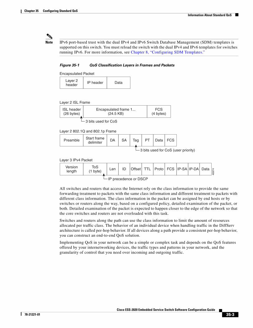
The classification is carried in the IP packet header, using 6 bits from the deprecated IP type of service (ToS) field to carry the classification (class) information. Classification can also be carried in the Layer 2 frame. These special bits in the Layer 2 frame or a Layer 3 packet are described here and shown in Figure 35-1:
• Prioritization bits in Layer 2 frames:
Layer 2 IEEE 802.1Q frame headers have a 2-byte Tag Control Information field that carries the CoS value in the three most-significant bits, which are called the User Priority bits. On ports configured as Layer 2 IEEE 802.1Q trunks, all traffic is in IEEE 802.1Q frames except for traffic in the native VLAN.
Other frame types cannot carry Layer 2 CoS values.
Layer 2 CoS values range from 0 for low priority to 7 for high priority.
• Prioritization bits in Layer 3 packets:
Layer 3 IP packets can carry either an IP precedence value or a Differentiated Services Code Point (DSCP) value. QoS supports the use of either value because DSCP values are backward-compatible with IP precedence values.
IP precedence values range from 0 to 7.
DSCP values range from 0 to 63.
35-2Cisco ESS-2020 Embedded Service Switch Software Configuration Guide
78-21221-01
Chapter 35 Configuring Standard QoSInformation About Standard QoS
Note IPv6 port-based trust with the dual IPv4 and IPv6 Switch Database Management (SDM) templates is supported on this switch. You must reload the switch with the dual IPv4 and IPv6 templates for switches running IPv6. For more information, see Chapter 8, “Configuring SDM Templates.”
Figure 35-1 QoS Classification Layers in Frames and Packets
All switches and routers that access the Internet rely on the class information to provide the same forwarding treatment to packets with the same class information and different treatment to packets with different class information. The class information in the packet can be assigned by end hosts or by switches or routers along the way, based on a configured policy, detailed examination of the packet, or both. Detailed examination of the packet is expected to happen closer to the edge of the network so that the core switches and routers are not overloaded with this task.
Switches and routers along the path can use the class information to limit the amount of resources allocated per traffic class. The behavior of an individual device when handling traffic in the DiffServ architecture is called per-hop behavior. If all devices along a path provide a consistent per-hop behavior, you can construct an end-to-end QoS solution.
Implementing QoS in your network can be a simple or complex task and depends on the QoS features offered by your internetworking devices, the traffic types and patterns in your network, and the granularity of control that you need over incoming and outgoing traffic.
4697
4
Encapsulated Packet
Layer 2header
IP header
3 bits used for CoS
Data
Layer 2 ISL Frame
ISL header(26 bytes)
Encapsulated frame 1...(24.5 KB)
FCS(4 bytes)
Layer 2 802.1Q and 802.1p Frame
Preamble Start framedelimiter
DA
Len
SA Tag PT Data FCS
Layer 3 IPv4 Packet
Versionlength
ToS(1 byte)
ID Offset TTL Proto FCS IP-SA IP-DA Data
3 bits used for CoS (user priority)
IP precedence or DSCP
35-3Cisco ESS-2020 Embedded Service Switch Software Configuration Guide
78-21221-01
Chapter 35 Configuring Standard QoSInformation About Standard QoS
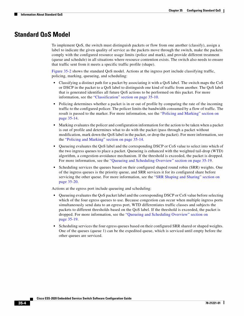
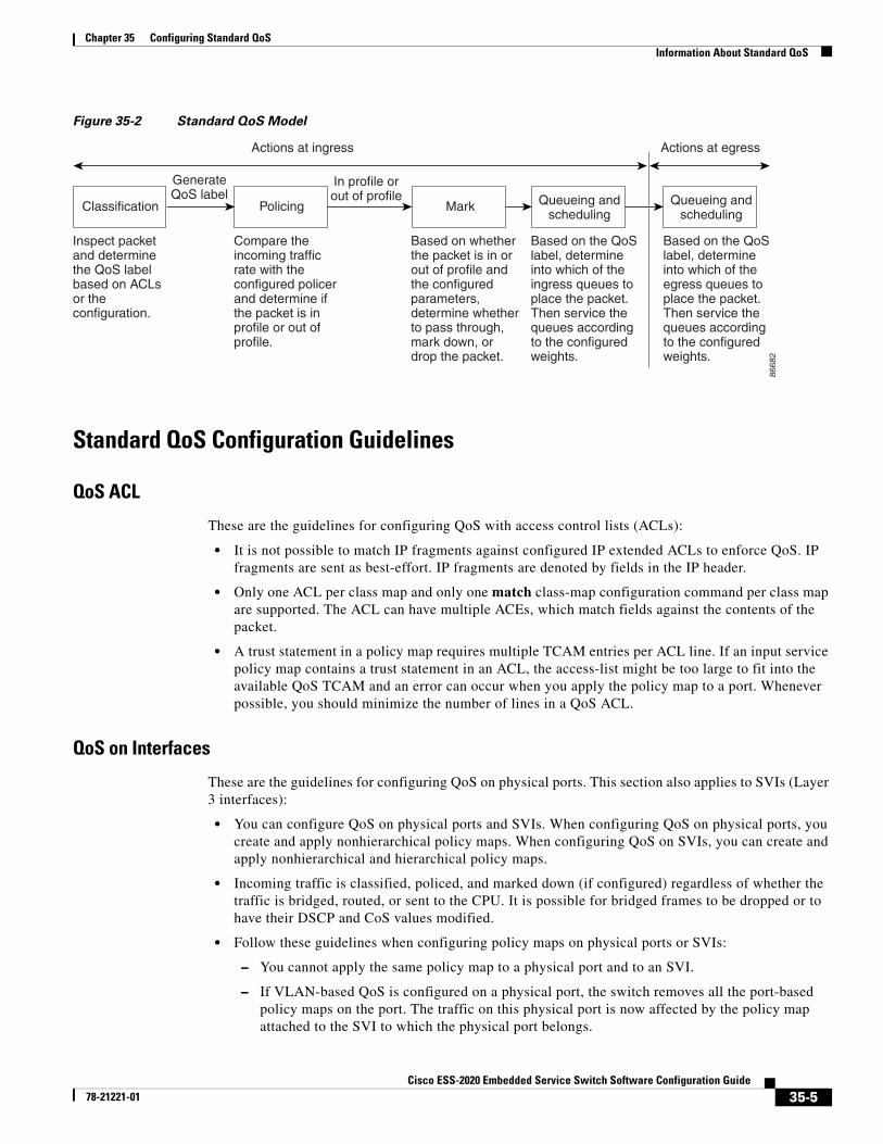
Standard QoS ModelTo implement QoS, the switch must distinguish packets or flow from one another (classify), assign a label to indicate the given quality of service as the packets move through the switch, make the packets comply with the configured resource usage limits (police and mark), and provide different treatment (queue and schedule) in all situations where resource contention exists. The switch also needs to ensure that traffic sent from it meets a specific traffic profile (shape).
Figure 35-2 shows the standard QoS model. Actions at the ingress port include classifying traffic, policing, marking, queueing, and scheduling:
• Classifying a distinct path for a packet by associating it with a QoS label. The switch maps the CoS or DSCP in the packet to a QoS label to distinguish one kind of traffic from another. The QoS label that is generated identifies all future QoS actions to be performed on this packet. For more information, see the “Classification” section on page 35-10.
• Policing determines whether a packet is in or out of profile by comparing the rate of the incoming traffic to the configured policer. The policer limits the bandwidth consumed by a flow of traffic. The result is passed to the marker. For more information, see the “Policing and Marking” section on page 35-14.
• Marking evaluates the policer and configuration information for the action to be taken when a packet is out of profile and determines what to do with the packet (pass through a packet without modification, mark down the QoS label in the packet, or drop the packet). For more information, see the “Policing and Marking” section on page 35-14.
• Queueing evaluates the QoS label and the corresponding DSCP or CoS value to select into which of the two ingress queues to place a packet. Queueing is enhanced with the weighted tail-drop (WTD) algorithm, a congestion-avoidance mechanism. If the threshold is exceeded, the packet is dropped. For more information, see the “Queueing and Scheduling Overview” section on page 35-19.
• Scheduling services the queues based on their configured shaped round robin (SRR) weights. One of the ingress queues is the priority queue, and SRR services it for its configured share before servicing the other queue. For more information, see the “SRR Shaping and Sharing” section on page 35-20.
Actions at the egress port include queueing and scheduling:
• Queueing evaluates the QoS packet label and the corresponding DSCP or CoS value before selecting which of the four egress queues to use. Because congestion can occur when multiple ingress ports simultaneously send data to an egress port, WTD differentiates traffic classes and subjects the packets to different thresholds based on the QoS label. If the threshold is exceeded, the packet is dropped. For more information, see the “Queueing and Scheduling Overview” section on page 35-19.
• Scheduling services the four egress queues based on their configured SRR shared or shaped weights. One of the queues (queue 1) can be the expedited queue, which is serviced until empty before the other queues are serviced.
35-4Cisco ESS-2020 Embedded Service Switch Software Configuration Guide
78-21221-01
Chapter 35 Configuring Standard QoSInformation About Standard QoS
Figure 35-2 Standard QoS Model
Standard QoS Configuration Guidelines
QoS ACL
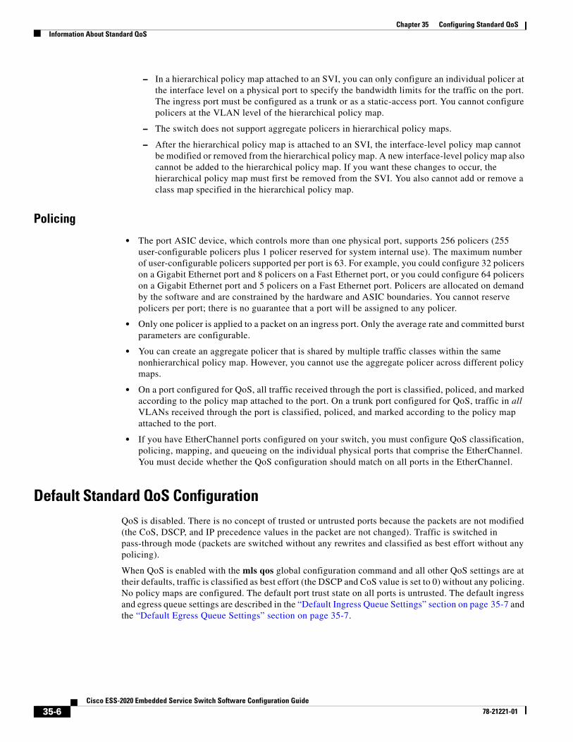
These are the guidelines for configuring QoS with access control lists (ACLs):
• It is not possible to match IP fragments against configured IP extended ACLs to enforce QoS. IP fragments are sent as best-effort. IP fragments are denoted by fields in the IP header.
• Only one ACL per class map and only one match class-map configuration command per class map are supported. The ACL can have multiple ACEs, which match fields against the contents of the packet.
• A trust statement in a policy map requires multiple TCAM entries per ACL line. If an input service policy map contains a trust statement in an ACL, the access-list might be too large to fit into the available QoS TCAM and an error can occur when you apply the policy map to a port. Whenever possible, you should minimize the number of lines in a QoS ACL.
QoS on Interfaces
These are the guidelines for configuring QoS on physical ports. This section also applies to SVIs (Layer 3 interfaces):
• You can configure QoS on physical ports and SVIs. When configuring QoS on physical ports, you create and apply nonhierarchical policy maps. When configuring QoS on SVIs, you can create and apply nonhierarchical and hierarchical policy maps.
• Incoming traffic is classified, policed, and marked down (if configured) regardless of whether the traffic is bridged, routed, or sent to the CPU. It is possible for bridged frames to be dropped or to have their DSCP and CoS values modified.
• Follow these guidelines when configuring policy maps on physical ports or SVIs:
– You cannot apply the same policy map to a physical port and to an SVI.
– If VLAN-based QoS is configured on a physical port, the switch removes all the port-based policy maps on the port. The traffic on this physical port is now affected by the policy map attached to the SVI to which the physical port belongs.
35-5Cisco ESS-2020 Embedded Service Switch Software Configuration Guide
78-21221-01
Chapter 35 Configuring Standard QoSInformation About Standard QoS
– In a hierarchical policy map attached to an SVI, you can only configure an individual policer at the interface level on a physical port to specify the bandwidth limits for the traffic on the port. The ingress port must be configured as a trunk or as a static-access port. You cannot configure policers at the VLAN level of the hierarchical policy map.
– The switch does not support aggregate policers in hierarchical policy maps.
– After the hierarchical policy map is attached to an SVI, the interface-level policy map cannot be modified or removed from the hierarchical policy map. A new interface-level policy map also cannot be added to the hierarchical policy map. If you want these changes to occur, the hierarchical policy map must first be removed from the SVI. You also cannot add or remove a class map specified in the hierarchical policy map.
Policing
• The port ASIC device, which controls more than one physical port, supports 256 policers (255 user-configurable policers plus 1 policer reserved for system internal use). The maximum number of user-configurable policers supported per port is 63. For example, you could configure 32 policers on a Gigabit Ethernet port and 8 policers on a Fast Ethernet port, or you could configure 64 policers on a Gigabit Ethernet port and 5 policers on a Fast Ethernet port. Policers are allocated on demand by the software and are constrained by the hardware and ASIC boundaries. You cannot reserve policers per port; there is no guarantee that a port will be assigned to any policer.
• Only one policer is applied to a packet on an ingress port. Only the average rate and committed burst parameters are configurable.
• You can create an aggregate policer that is shared by multiple traffic classes within the same nonhierarchical policy map. However, you cannot use the aggregate policer across different policy maps.
• On a port configured for QoS, all traffic received through the port is classified, policed, and marked according to the policy map attached to the port. On a trunk port configured for QoS, traffic in all VLANs received through the port is classified, policed, and marked according to the policy map attached to the port.
• If you have EtherChannel ports configured on your switch, you must configure QoS classification, policing, mapping, and queueing on the individual physical ports that comprise the EtherChannel. You must decide whether the QoS configuration should match on all ports in the EtherChannel.
Default Standard QoS ConfigurationQoS is disabled. There is no concept of trusted or untrusted ports because the packets are not modified (the CoS, DSCP, and IP precedence values in the packet are not changed). Traffic is switched in pass-through mode (packets are switched without any rewrites and classified as best effort without any policing).
When QoS is enabled with the mls qos global configuration command and all other QoS settings are at their defaults, traffic is classified as best effort (the DSCP and CoS value is set to 0) without any policing. No policy maps are configured. The default port trust state on all ports is untrusted. The default ingress and egress queue settings are described in the “Default Ingress Queue Settings” section on page 35-7 and the “Default Egress Queue Settings” section on page 35-7.
35-6Cisco ESS-2020 Embedded Service Switch Software Configuration Guide
78-21221-01
Chapter 35 Configuring Standard QoSInformation About Standard QoS
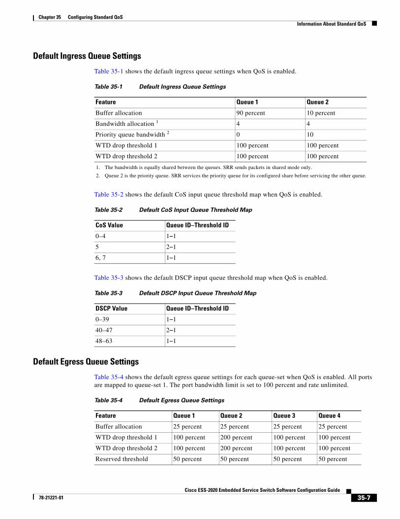
Default Ingress Queue Settings
Table 35-1 shows the default ingress queue settings when QoS is enabled.
Table 35-2 shows the default CoS input queue threshold map when QoS is enabled.
Table 35-3 shows the default DSCP input queue threshold map when QoS is enabled.
Default Egress Queue Settings
Table 35-4 shows the default egress queue settings for each queue-set when QoS is enabled. All ports are mapped to queue-set 1. The port bandwidth limit is set to 100 percent and rate unlimited.
Table 35-1 Default Ingress Queue Settings
Feature Queue 1 Queue 2
Buffer allocation 90 percent 10 percent
Bandwidth allocation 1
1. The bandwidth is equally shared between the queues. SRR sends packets in shared mode only.
4 4
Priority queue bandwidth 2
2. Queue 2 is the priority queue. SRR services the priority queue for its configured share before servicing the other queue.
0 10
WTD drop threshold 1 100 percent 100 percent
WTD drop threshold 2 100 percent 100 percent
Table 35-2 Default CoS Input Queue Threshold Map
CoS Value Queue ID–Threshold ID
0–4 1–1
5 2–1
6, 7 1–1
Table 35-3 Default DSCP Input Queue Threshold Map
DSCP Value Queue ID–Threshold ID
0–39 1–1
40–47 2–1
48–63 1–1
Table 35-4 Default Egress Queue Settings
Feature Queue 1 Queue 2 Queue 3 Queue 4
Buffer allocation 25 percent 25 percent 25 percent 25 percent
WTD drop threshold 1 100 percent 200 percent 100 percent 100 percent
WTD drop threshold 2 100 percent 200 percent 100 percent 100 percent
Reserved threshold 50 percent 50 percent 50 percent 50 percent
35-7Cisco ESS-2020 Embedded Service Switch Software Configuration Guide
78-21221-01
Chapter 35 Configuring Standard QoSInformation About Standard QoS
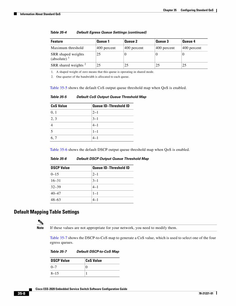
Table 35-5 shows the default CoS output queue threshold map when QoS is enabled.
Table 35-6 shows the default DSCP output queue threshold map when QoS is enabled.
Default Mapping Table Settings
Note If these values are not appropriate for your network, you need to modify them.
Table 35-7 shows the DSCP-to-CoS map to generate a CoS value, which is used to select one of the four egress queues.
Maximum threshold 400 percent 400 percent 400 percent 400 percent
SRR shaped weights (absolute) 1
25 0 0 0
SRR shared weights 2 25 25 25 25
1. A shaped weight of zero means that this queue is operating in shared mode.
2. One quarter of the bandwidth is allocated to each queue.
Table 35-4 Default Egress Queue Settings (continued)
Feature Queue 1 Queue 2 Queue 3 Queue 4
Table 35-5 Default CoS Output Queue Threshold Map
CoS Value Queue ID–Threshold ID
0, 1 2–1
2, 3 3–1
4 4–1
5 1–1
6, 7 4–1
Table 35-6 Default DSCP Output Queue Threshold Map
DSCP Value Queue ID–Threshold ID
0–15 2–1
16–31 3–1
32–39 4–1
40–47 1–1
48–63 4–1
Table 35-7 Default DSCP-to-CoS Map
DSCP Value CoS Value
0–7 0
8–15 1
35-8Cisco ESS-2020 Embedded Service Switch Software Configuration Guide
78-21221-01
Chapter 35 Configuring Standard QoSInformation About Standard QoS
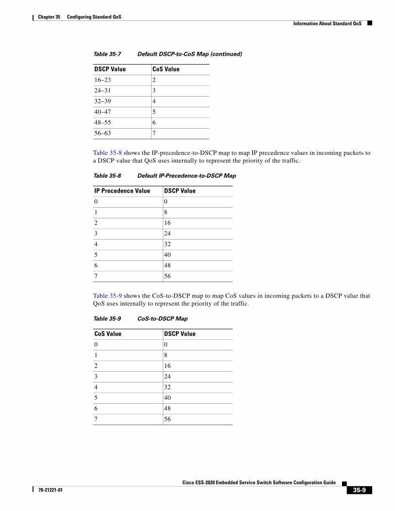
Table 35-8 shows the IP-precedence-to-DSCP map to map IP precedence values in incoming packets to a DSCP value that QoS uses internally to represent the priority of the traffic.
Table 35-9 shows the CoS-to-DSCP map to map CoS values in incoming packets to a DSCP value that QoS uses internally to represent the priority of the traffic.
16–23 2
24–31 3
32–39 4
40–47 5
48–55 6
56–63 7
Table 35-7 Default DSCP-to-CoS Map (continued)
DSCP Value CoS Value
Table 35-8 Default IP-Precedence-to-DSCP Map
IP Precedence Value DSCP Value
0 0
1 8
2 16
3 24
4 32
5 40
6 48
7 56
Table 35-9 CoS-to-DSCP Map
CoS Value DSCP Value
0 0
1 8
2 16
3 24
4 32
5 40
6 48
7 56
35-9Cisco ESS-2020 Embedded Service Switch Software Configuration Guide
78-21221-01
Chapter 35 Configuring Standard QoSInformation About Standard QoS
The default DSCP-to-DSCP-mutation map is a null map, which maps an incoming DSCP value to the same DSCP value.
The default policed-DSCP map is a null map, which maps an incoming DSCP value to the same DSCP value (no markdown).
ClassificationClassification is the process of distinguishing one kind of traffic from another by examining the fields in the packet. Classification is enabled only if QoS is globally enabled on the switch. By default, QoS is globally disabled, so no classification occurs.
During classification, the switch performs a lookup and assigns a QoS label to the packet. The QoS label identifies all QoS actions to be performed on the packet and from which queue the packet is sent.
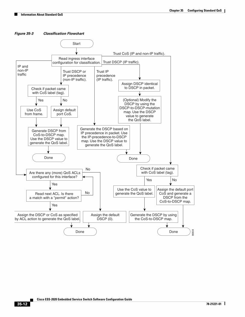
The QoS label is based on the DSCP or the CoS value in the packet and decides the queueing and scheduling actions to perform on the packet. The label is mapped according to the trust setting and the packet type as shown in Figure 35-3 on page 35-12.
You specify which fields in the frame or packet that you want to use to classify incoming traffic. For non-IP traffic, you have these classification options as shown in Figure 35-3:
• Trust the CoS value in the incoming frame (configure the port to trust CoS). Then use the configurable CoS-to-DSCP map to generate a DSCP value for the packet. Layer 2 ISL frame headers carry the CoS value in the 3 least-significant bits of the 1-byte User field. Layer 2 IEEE 802.1Q frame headers carry the CoS value in the 3 most-significant bits of the Tag Control Information field. CoS values range from 0 for low priority to 7 for high priority.
• Trust the DSCP or trust IP precedence value in the incoming frame. These configurations are meaningless for non-IP traffic. If you configure a port with either of these options and non-IP traffic is received, the switch assigns a CoS value and generates an internal DSCP value from the CoS-to-DSCP map. The switch uses the internal DSCP value to generate a CoS value representing the priority of the traffic.
• Perform the classification based on a configured Layer 2 MAC access control list (ACL), which can examine the MAC source address, the MAC destination address, and other fields. If no ACL is configured, the packet is assigned 0 as the DSCP and CoS values, which means best-effort traffic. Otherwise, the policy-map action specifies a DSCP or CoS value to assign to the incoming frame.
For IP traffic, you have these classification options as shown in Figure 35-3:
• Trust the DSCP value in the incoming packet (configure the port to trust DSCP), and assign the same DSCP value to the packet. The IETF defines the 6 most-significant bits of the 1-byte ToS field as the DSCP. The priority represented by a particular DSCP value is configurable. DSCP values range from 0 to 63.
For ports that are on the boundary between two QoS administrative domains, you can modify the DSCP to another value by using the configurable DSCP-to-DSCP-mutation map.
• Trust the IP precedence value in the incoming packet (configure the port to trust IP precedence), and generate a DSCP value for the packet by using the configurable IP-precedence-to-DSCP map. The IP Version 4 specification defines the 3 most-significant bits of the 1-byte ToS field as the IP precedence. IP precedence values range from 0 for low priority to 7 for high priority.
• Trust the CoS value (if present) in the incoming packet, and generate a DSCP value for the packet by using the CoS-to-DSCP map. If the CoS value is not present, use the default port CoS value.
35-10Cisco ESS-2020 Embedded Service Switch Software Configuration Guide
78-21221-01
Chapter 35 Configuring Standard QoSInformation About Standard QoS
• Perform the classification based on a configured IP standard or an extended ACL, which examines various fields in the IP header. If no ACL is configured, the packet is assigned 0 as the DSCP and CoS values, which means best-effort traffic. Otherwise, the policy-map action specifies a DSCP or CoS value to assign to the incoming frame.
For information on the maps described in this section, see the “Mapping Tables” section on page 35-18. For configuration information on port trust states, see the “Configuring Classification Using Port Trust States” section on page 35-32.
After classification, the packet is sent to the policing, marking, and the ingress queueing and scheduling stages.
35-11Cisco ESS-2020 Embedded Service Switch Software Configuration Guide
78-21221-01
Chapter 35 Configuring Standard QoSInformation About Standard QoS
Figure 35-3 Classification Flowchart
8683
4
Generate the DSCP based onIP precedence in packet. Usethe IP-precedence-to-DSCPmap. Use the DSCP value to
generate the QoS label.
Assign defaultport CoS.
Yes
Yes
No
No
No
Yes No
(Optional) Modify theDSCP by using the
DSCP-to-DSCP-mutationmap. Use the DSCP
value to generatethe QoS label.
Read ingress interfaceconfiguration for classification.
Assign DSCP identicalto DSCP in packet.
Check if packet camewith CoS label (tag).
Use the CoS value togenerate the QoS label.
Generate DSCP fromCoS-to-DSCP map.
Use the DSCP value togenerate the QoS label.
Yes
Read next ACL. Is therea match with a "permit" action?
Assign the DSCP or CoS as specifiedby ACL action to generate the QoS label.
Assign the defaultDSCP (0).
Are there any (more) QoS ACLsconfigured for this interface?
Check if packet camewith CoS label (tag).
Use CoSfrom frame.
Start
Trust CoS (IP and non-IP traffic).
IP andnon-IPtraffic
Trust DSCP orIP precedence(non-IP traffic).
Trust IPprecedence(IP traffic).
Trust DSCP (IP traffic).
DoneDone
DoneDone
Assign the default portCoS and generate a
DSCP from theCoS-to-DSCP map.
Generate the DSCP by usingthe CoS-to-DSCP map.
35-12Cisco ESS-2020 Embedded Service Switch Software Configuration Guide
78-21221-01
Chapter 35 Configuring Standard QoSInformation About Standard QoS
Classification Based on QoS ACLs
You can use IP standard, IP extended, or Layer 2 MAC ACLs to define a group of packets with the same characteristics (class). In the QoS context, the permit and deny actions in the access control entries (ACEs) have different meanings than with security ACLs:
• If a match with a permit action is encountered (first-match principle), the specified QoS-related action is taken.
• If a match with a deny action is encountered, the ACL being processed is skipped, and the next ACL is processed.
• If no match with a permit action is encountered and all the ACEs have been examined, no QoS processing occurs on the packet, and the switch offers best-effort service to the packet.
• If multiple ACLs are configured on a port, the lookup stops after the packet matches the first ACL with a permit action, and QoS processing begins.
Note When creating an access list, remember that, by default, the end of the access list contains an implicit deny statement for everything if it did not find a match before reaching the end.
After a traffic class has been defined with the ACL, you can attach a policy to it. A policy might contain multiple classes with actions specified for each one of them. A policy might include commands to classify the class as a particular aggregate (for example, assign a DSCP) or rate-limit the class. This policy is then attached to a particular port on which it becomes effective.
You implement IP ACLs to classify IP traffic by using the access-list global configuration command; you implement Layer 2 MAC ACLs to classify non-IP traffic by using the mac access-list extended global configuration command. For configuration information, see the “Configuring a QoS Policy” section on page 35-36.
Classification Based on Class Maps and Policy Maps
A class map is a mechanism that you use to name a specific traffic flow (or class) and to isolate it from all other traffic. The class map defines the criteria used to match against a specific traffic flow to further classify it. The criteria can include matching the access group defined by the ACL or matching a specific list of DSCP or IP precedence values. If you have more than one type of traffic that you want to classify, you can create another class map and use a different name. After a packet is matched against the class-map criteria, you further classify it through the use of a policy map.
A policy map specifies which traffic class to act on. Actions can include trusting the CoS, DSCP, or IP precedence values in the traffic class; setting a specific DSCP or IP precedence value in the traffic class; or specifying the traffic bandwidth limitations and the action to take when the traffic is out of profile. Before a policy map can be effective, you must attach it to a port.
You create a class map by using the class-map global configuration command or the class policy-map configuration command. You should use the class-map command when the map is shared among many ports. When you enter the class-map command, the switch enters the class-map configuration mode. In this mode, you define the match criterion for the traffic by using the match class-map configuration command.
You create and name a policy map by using the policy-map global configuration command. When you enter this command, the switch enters the policy-map configuration mode. In this mode, you specify the actions to take on a specific traffic class by using the class, trust, or set policy-map configuration and policy-map class configuration commands.
35-13Cisco ESS-2020 Embedded Service Switch Software Configuration Guide
78-21221-01
Chapter 35 Configuring Standard QoSInformation About Standard QoS
The policy map can contain the police and police aggregate policy-map class configuration commands, which define the policer, the bandwidth limitations of the traffic, and the action to take if the limits are exceeded.
To enable the policy map, you attach it to a port by using the service-policy interface configuration command.
You can apply a nonhierarchical policy map to a physical port or an SVI. However, a hierarchical policy map can only be applied to an SVI. A hierarchical policy map contains two levels. The first level, the VLAN level, specifies the actions to be taken against a traffic flow on the SVI. The second level, the interface level, specifies the actions to be taken against the traffic on the physical ports that belong to the SVI. The interface-level actions are specified in the interface-level policy map.
For more information, see the “Policing and Marking” section on page 35-14. For configuration information, see the “Configuring a QoS Policy” section on page 35-36.
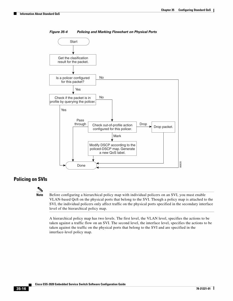
Policing and MarkingAfter a packet is classified and has a DSCP-based or CoS-based QoS label assigned to it, the policing and marking process can begin as shown in Figure 35-4.
Policing involves creating a policer that specifies the bandwidth limits for the traffic. Packets that exceed the limits are out of profile or nonconforming. Each policer decides on a packet-by-packet basis whether the packet is in or out of profile and specifies the actions on the packet. These actions, carried out by the marker, include passing through the packet without modification, dropping the packet, or modifying (marking down) the assigned DSCP of the packet and allowing the packet to pass through. The configurable policed-DSCP map provides the packet with a new DSCP-based QoS label. For information on the policed-DSCP map, see the “Mapping Tables” section on page 35-18. Marked-down packets use the same queues as the original QoS label to prevent packets in a flow from getting out of order.
Note All traffic, regardless of whether it is bridged or routed, is subjected to a policer, if one is configured. As a result, bridged packets might be dropped or might have their DSCP or CoS fields modified when they are policed and marked.
You can configure policing on a physical port or an SVI. On a physical port, you can configure the trust state, set a new DSCP or IP precedence value in the packet, or define an individual or aggregate policer. For more information about configuring policing on physical ports, see the “Policing on Physical Ports” section on page 35-15. When configuring policy maps on an SVI, you can create a hierarchical policy map and can define an individual policer only in the secondary interface-level policy map. For more information, see the “Policing on SVIs” section on page 35-16.
After you configure the policy map and policing actions, attach the policy to an ingress port or SVI by using the service-policy interface configuration command.
35-14Cisco ESS-2020 Embedded Service Switch Software Configuration Guide
78-21221-01
Chapter 35 Configuring Standard QoSInformation About Standard QoS
Policing on Physical Ports
In policy maps on physical ports, you can create these types of policers:
• Individual—QoS applies the bandwidth limits specified in the policer separately to each matched traffic class. You configure this type of policer within a policy map by using the police policy-map class configuration command.
• Aggregate—QoS applies the bandwidth limits specified in an aggregate policer cumulatively to all matched traffic flows. You configure this type of policer by specifying the aggregate policer name within a policy map by using the police aggregate policy-map class configuration command. You specify the bandwidth limits of the policer by using the mls qos aggregate-policer global configuration command. In this way, the aggregate policer is shared by multiple classes of traffic within a policy map.
Note You can only configure individual policers on an SVI.
Policing uses a token-bucket algorithm. As each frame is received by the switch, a token is added to the bucket. The bucket has a hole in it and leaks at a rate that you specify as the average traffic rate in bits per second. Each time a token is added to the bucket, the switch verifies that there is enough room in the bucket. If there is not enough room, the packet is marked as nonconforming, and the specified policer action is taken (dropped or marked down).
How quickly the bucket fills is a function of the bucket depth (burst-byte), the rate at which the tokens are removed (rate-b/s), and the duration of the burst above the average rate. The size of the bucket imposes an upper limit on the burst length and limits the number of frames that can be transmitted back-to-back. If the burst is short, the bucket does not overflow, and no action is taken against the traffic flow. However, if a burst is long and at a higher rate, the bucket overflows, and the policing actions are taken against the frames in that burst.
You configure the bucket depth (the maximum burst that is tolerated before the bucket overflows) by using the burst-byte option of the police policy-map class configuration command or the mls qos aggregate-policer global configuration command. You configure how fast (the average rate) that the tokens are removed from the bucket by using the rate-bps option of the police policy-map class configuration command or the mls qos aggregate-policer global configuration command.
Figure 35-4 shows the policing and marking process. These types of policy maps are configured:
• A nonhierarchical policy map on a physical port.
• The interface level of a hierarchical policy map attached to an SVI. The physical ports are specified in this secondary policy map.
35-15Cisco ESS-2020 Embedded Service Switch Software Configuration Guide
78-21221-01
Chapter 35 Configuring Standard QoSInformation About Standard QoS
Figure 35-4 Policing and Marking Flowchart on Physical Ports
Policing on SVIs
Note Before configuring a hierarchical policy map with individual policers on an SVI, you must enable VLAN-based QoS on the physical ports that belong to the SVI. Though a policy map is attached to the SVI, the individual policers only affect traffic on the physical ports specified in the secondary interface level of the hierarchical policy map.
A hierarchical policy map has two levels. The first level, the VLAN level, specifies the actions to be taken against a traffic flow on an SVI. The second level, the interface level, specifies the actions to be taken against the traffic on the physical ports that belong to the SVI and are specified in the interface-level policy map.
8683
5
Yes
Yes
No
No
Passthrough Drop
Mark
Get the clasificationresult for the packet.
Is a policer configuredfor this packet?
Check if the packet is inprofile by querying the policer.
Check out-of-profile actionconfigured for this policer.
Drop packet.
Modify DSCP according to thepoliced-DSCP map. Generate
a new QoS label.
Start
Done
35-16Cisco ESS-2020 Embedded Service Switch Software Configuration Guide
78-21221-01
Chapter 35 Configuring Standard QoSInformation About Standard QoS
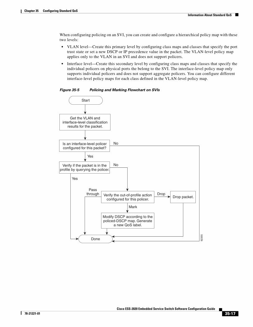
When configuring policing on an SVI, you can create and configure a hierarchical policy map with these two levels:
• VLAN level—Create this primary level by configuring class maps and classes that specify the port trust state or set a new DSCP or IP precedence value in the packet. The VLAN-level policy map applies only to the VLAN in an SVI and does not support policers.
• Interface level—Create this secondary level by configuring class maps and classes that specify the individual policers on physical ports the belong to the SVI. The interface-level policy map only supports individual policers and does not support aggregate policers. You can configure different interface-level policy maps for each class defined in the VLAN-level policy map.
Figure 35-5 Policing and Marking Flowchart on SVIs
9235
5
Yes
Yes
No
No
Passthrough Drop
Mark
Get the VLAN andinterface-level classification
results for the packet.
Is an interface-level policerconfigured for this packet?
Verify if the packet is in theprofile by querying the policer.
Verify the out-of-profile actionconfigured for this policer.
Drop packet.
Modify DSCP according to thepoliced-DSCP map. Generate
a new QoS label.
Start
Done
35-17Cisco ESS-2020 Embedded Service Switch Software Configuration Guide
78-21221-01

Chapter 35 Configuring Standard QoSInformation About Standard QoS
Mapping TablesDuring QoS processing, the switch represents the priority of all traffic (including non-IP traffic) with an QoS label based on the DSCP or CoS value from the classification stage:
• During classification, QoS uses configurable mapping tables to derive a corresponding DSCP or CoS value from a received CoS, DSCP, or IP precedence value. These maps include the CoS-to-DSCP map and the IP-precedence-to-DSCP map. You configure these maps by using the mls qos map cos-dscp and the mls qos map ip-prec-dscp global configuration commands.
On an ingress port configured in the DSCP-trusted state, if the DSCP values are different between the QoS domains, you can apply the configurable DSCP-to-DSCP-mutation map to the port that is on the boundary between the two QoS domains. You configure this map by using the mls qos map dscp-mutation global configuration command.
• During policing, QoS can assign another DSCP value to an IP or a non-IP packet (if the packet is out of profile and the policer specifies a marked-down value). This configurable map is called the policed-DSCP map. You configure this map by using the mls qos map policed-dscp global configuration command.
• Before the traffic reaches the scheduling stage, QoS stores the packet in an ingress and an egress queue according to the QoS label. The QoS label is based on the DSCP or the CoS value in the packet and selects the queue through the DSCP input and output queue threshold maps or through the CoS input and output queue threshold maps. In addition to an ingress or an egress queue, the QOS label also identifies the WTD threshold value. You configure these maps by using the mls qos srr-queue {input | output} dscp-map and the mls qos srr-queue {input | output} cos-map global configuration commands.
The CoS-to-DSCP, DSCP-to-CoS, and the IP-precedence-to-DSCP maps have default values that might or might not be appropriate for your network.
The default DSCP-to-DSCP-mutation map and the default policed-DSCP map are null maps; they map an incoming DSCP value to the same DSCP value. The DSCP-to-DSCP-mutation map is the only map you apply to a specific port. All other maps apply to the entire switch.
For configuration information, see the “Configuring DSCP Maps” section on page 35-47.
For information about the DSCP and CoS input queue threshold maps, see the “Queueing and Scheduling on Ingress Queues” section on page 35-21. For information about the DSCP and CoS output queue threshold maps, see the “Queueing and Scheduling on Egress Queues” section on page 35-22.
35-18Cisco ESS-2020 Embedded Service Switch Software Configuration Guide
78-21221-01
Chapter 35 Configuring Standard QoSInformation About Standard QoS
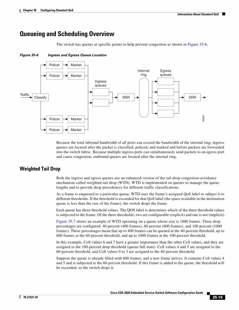
Queueing and Scheduling OverviewThe switch has queues at specific points to help prevent congestion as shown in Figure 35-6.
Figure 35-6 Ingress and Egress Queue Location
Because the total inbound bandwidth of all ports can exceed the bandwidth of the internal ring, ingress queues are located after the packet is classified, policed, and marked and before packets are forwarded into the switch fabric. Because multiple ingress ports can simultaneously send packets to an egress port and cause congestion, outbound queues are located after the internal ring.
Weighted Tail Drop
Both the ingress and egress queues use an enhanced version of the tail-drop congestion-avoidance mechanism called weighted tail drop (WTD). WTD is implemented on queues to manage the queue lengths and to provide drop precedences for different traffic classifications.
As a frame is enqueued to a particular queue, WTD uses the frame’s assigned QoS label to subject it to different thresholds. If the threshold is exceeded for that QoS label (the space available in the destination queue is less than the size of the frame), the switch drops the frame.
Each queue has three threshold values. The QOS label is determines which of the three threshold values is subjected to the frame. Of the three thresholds, two are configurable (explicit) and one is not (implicit).
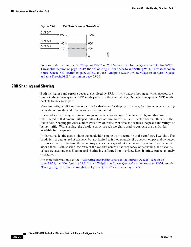
Figure 35-7 shows an example of WTD operating on a queue whose size is 1000 frames. Three drop percentages are configured: 40 percent (400 frames), 60 percent (600 frames), and 100 percent (1000 frames). These percentages mean that up to 400 frames can be queued at the 40-percent threshold, up to 600 frames at the 60-percent threshold, and up to 1000 frames at the 100-percent threshold.
In this example, CoS values 6 and 7 have a greater importance than the other CoS values, and they are assigned to the 100-percent drop threshold (queue-full state). CoS values 4 and 5 are assigned to the 60-percent threshold, and CoS values 0 to 3 are assigned to the 40-percent threshold.
Suppose the queue is already filled with 600 frames, and a new frame arrives. It contains CoS values 4 and 5 and is subjected to the 60-percent threshold. If this frame is added to the queue, the threshold will be exceeded, so the switch drops it.
MarkerPolicer
MarkerPolicer
Marker
Ingressqueues
Internalring
EgressqueuesPolicer
MarkerPolicer
ClassifyTraffic
SRRSRR
9056
3
35-19Cisco ESS-2020 Embedded Service Switch Software Configuration Guide
78-21221-01
Chapter 35 Configuring Standard QoSInformation About Standard QoS
Figure 35-7 WTD and Queue Operation
For more information, see the “Mapping DSCP or CoS Values to an Ingress Queue and Setting WTD Thresholds” section on page 35-49, the “Allocating Buffer Space to and Setting WTD Thresholds for an Egress Queue-Set” section on page 35-52, and the “Mapping DSCP or CoS Values to an Egress Queue and to a Threshold ID” section on page 35-53.
SRR Shaping and Sharing
Both the ingress and egress queues are serviced by SRR, which controls the rate at which packets are sent. On the ingress queues, SRR sends packets to the internal ring. On the egress queues, SRR sends packets to the egress port.
You can configure SRR on egress queues for sharing or for shaping. However, for ingress queues, sharing is the default mode, and it is the only mode supported.
In shaped mode, the egress queues are guaranteed a percentage of the bandwidth, and they are rate-limited to that amount. Shaped traffic does not use more than the allocated bandwidth even if the link is idle. Shaping provides a more even flow of traffic over time and reduces the peaks and valleys of bursty traffic. With shaping, the absolute value of each weight is used to compute the bandwidth available for the queues.
In shared mode, the queues share the bandwidth among them according to the configured weights. The bandwidth is guaranteed at this level but not limited to it. For example, if a queue is empty and no longer requires a share of the link, the remaining queues can expand into the unused bandwidth and share it among them. With sharing, the ratio of the weights controls the frequency of dequeuing; the absolute values are meaningless. Shaping and sharing is configured per interface. Each interface can be uniquely configured.
For more information, see the “Allocating Bandwidth Between the Ingress Queues” section on page 35-51, the “Configuring SRR Shaped Weights on Egress Queues” section on page 35-54, and the “Configuring SRR Shared Weights on Egress Queues” section on page 35-55.
CoS 6-7100%
60%
40%
1000
600
400
0
CoS 4-5
CoS 0-3
8669
2
35-20Cisco ESS-2020 Embedded Service Switch Software Configuration Guide
78-21221-01
Chapter 35 Configuring Standard QoSInformation About Standard QoS
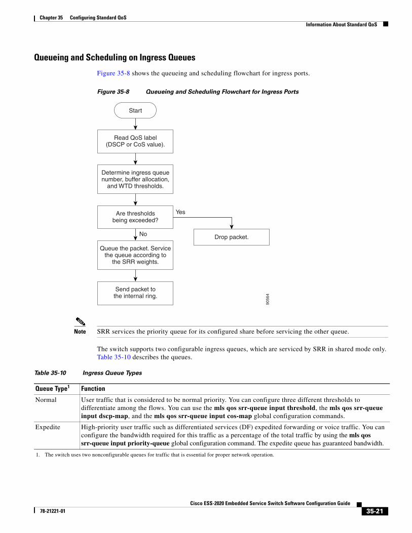
Queueing and Scheduling on Ingress Queues
Figure 35-8 shows the queueing and scheduling flowchart for ingress ports.
Figure 35-8 Queueing and Scheduling Flowchart for Ingress Ports
Note SRR services the priority queue for its configured share before servicing the other queue.
The switch supports two configurable ingress queues, which are serviced by SRR in shared mode only. Table 35-10 describes the queues.
9056
4
Read QoS label(DSCP or CoS value).
Determine ingress queuenumber, buffer allocation,
and WTD thresholds.
Are thresholdsbeing exceeded?
Queue the packet. Servicethe queue according to
the SRR weights.
Send packet tothe internal ring.
Drop packet.
Start
Yes
No
Table 35-10 Ingress Queue Types
Queue Type1
1. The switch uses two nonconfigurable queues for traffic that is essential for proper network operation.
Function
Normal User traffic that is considered to be normal priority. You can configure three different thresholds to differentiate among the flows. You can use the mls qos srr-queue input threshold, the mls qos srr-queue input dscp-map, and the mls qos srr-queue input cos-map global configuration commands.
Expedite High-priority user traffic such as differentiated services (DF) expedited forwarding or voice traffic. You can configure the bandwidth required for this traffic as a percentage of the total traffic by using the mls qos srr-queue input priority-queue global configuration command. The expedite queue has guaranteed bandwidth.
35-21Cisco ESS-2020 Embedded Service Switch Software Configuration Guide
78-21221-01
Chapter 35 Configuring Standard QoSInformation About Standard QoS
You assign each packet that flows through the switch to a queue and to a threshold. Specifically, you map DSCP or CoS values to an ingress queue and map DSCP or CoS values to a threshold ID. You use the mls qos srr-queue input dscp-map queue queue-id {dscp1...dscp8 | threshold threshold-id dscp1...dscp8} or the mls qos srr-queue input cos-map queue queue-id {cos1...cos8 | threshold threshold-id cos1...cos8} global configuration command. You can display the DSCP input queue threshold map and the CoS input queue threshold map by using the show mls qos maps privileged EXEC command.
WTD Thresholds
The queues use WTD to support distinct drop percentages for different traffic classes. Each queue has three drop thresholds: two configurable (explicit) WTD thresholds and one nonconfigurable (implicit) threshold preset to the queue-full state. You assign the two explicit WTD threshold percentages for threshold ID 1 and ID 2 to the ingress queues by using the mls qos srr-queue input threshold queue-id threshold-percentage1 threshold-percentage2 global configuration command. Each threshold value is a percentage of the total number of allocated buffers for the queue. The drop threshold for threshold ID 3 is preset to the queue-full state, and you cannot modify it. For more information about how WTD works, see the “Weighted Tail Drop” section on page 35-19.
Buffer and Bandwidth Allocation
You define the ratio (allocate the amount of space) with which to divide the ingress buffers between the two queues by using the mls qos srr-queue input buffers percentage1 percentage2 global configuration command. The buffer allocation together with the bandwidth allocation control how much data can be buffered and sent before packets are dropped. You allocate bandwidth as a percentage by using the mls qos srr-queue input bandwidth weight1 weight2 global configuration command. The ratio of the weights is the ratio of the frequency in which the SRR scheduler sends packets from each queue.
Priority Queueing
You can configure one ingress queue as the priority queue by using the mls qos srr-queue input priority-queue queue-id bandwidth weight global configuration command. The priority queue should be used for traffic (such as voice) that requires guaranteed delivery because this queue is guaranteed part of the bandwidth regardless of the load on the internal ring.
SRR services the priority queue for its configured weight as specified by the bandwidth keyword in the mls qos srr-queue input priority-queue queue-id bandwidth weight global configuration command. Then, SRR shares the remaining bandwidth with both ingress queues and services them as specified by the weights configured with the mls qos srr-queue input bandwidth weight1 weight2 global configuration command.
You can combine the commands described in this section to prioritize traffic by placing packets with particular DSCPs or CoSs into certain queues, by allocating a large queue size or by servicing the queue more frequently, and by adjusting queue thresholds so that packets with lower priorities are dropped. For configuration information, see the “Configuring Ingress Queue Characteristics” section on page 35-49.
Queueing and Scheduling on Egress Queues
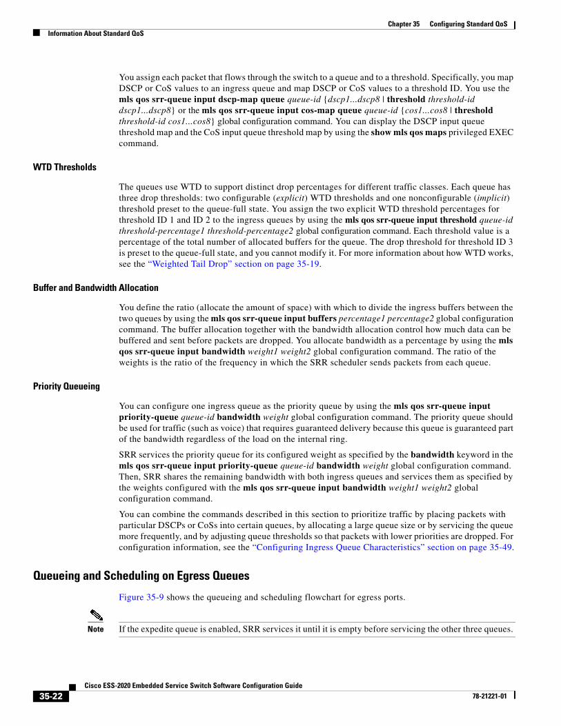
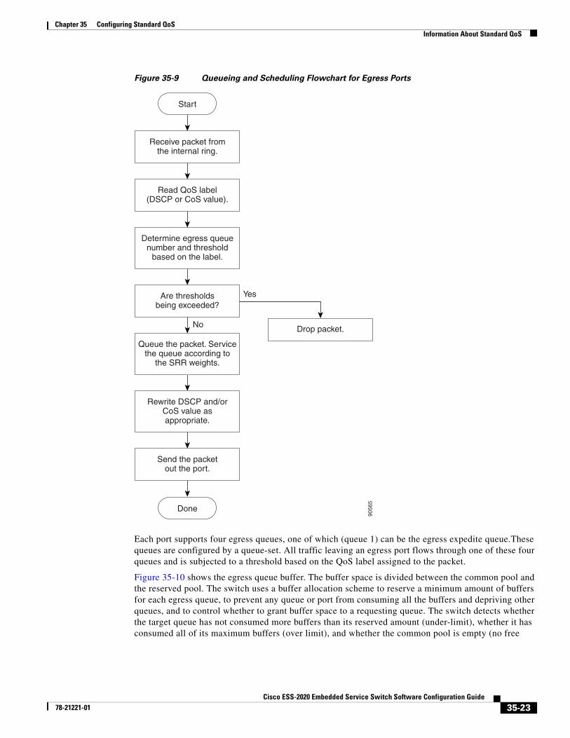
Figure 35-9 shows the queueing and scheduling flowchart for egress ports.
Note If the expedite queue is enabled, SRR services it until it is empty before servicing the other three queues.
35-22Cisco ESS-2020 Embedded Service Switch Software Configuration Guide
78-21221-01
Chapter 35 Configuring Standard QoSInformation About Standard QoS
Figure 35-9 Queueing and Scheduling Flowchart for Egress Ports
Each port supports four egress queues, one of which (queue 1) can be the egress expedite queue.These queues are configured by a queue-set. All traffic leaving an egress port flows through one of these four queues and is subjected to a threshold based on the QoS label assigned to the packet.
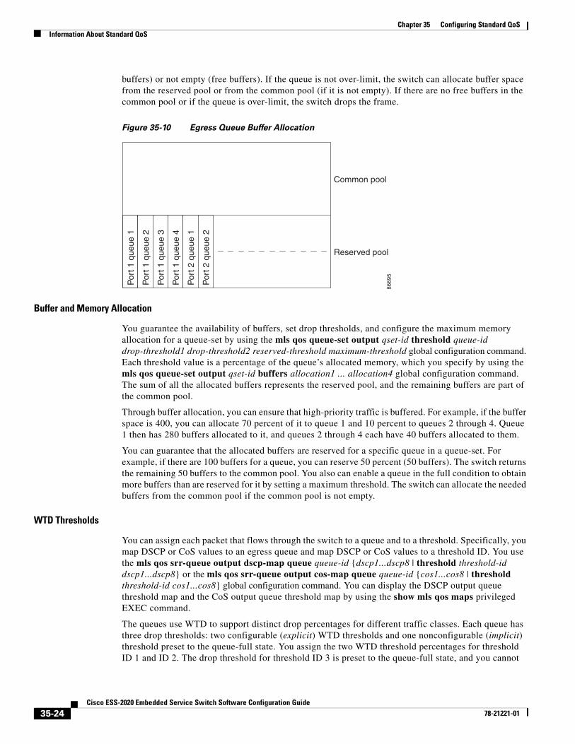
Figure 35-10 shows the egress queue buffer. The buffer space is divided between the common pool and the reserved pool. The switch uses a buffer allocation scheme to reserve a minimum amount of buffers for each egress queue, to prevent any queue or port from consuming all the buffers and depriving other queues, and to control whether to grant buffer space to a requesting queue. The switch detects whether the target queue has not consumed more buffers than its reserved amount (under-limit), whether it has consumed all of its maximum buffers (over limit), and whether the common pool is empty (no free
9056
5
Receive packet fromthe internal ring.
Read QoS label(DSCP or CoS value).
Determine egress queuenumber and threshold
based on the label.
Are thresholdsbeing exceeded?
Send the packetout the port.
Queue the packet. Servicethe queue according to
the SRR weights.
Drop packet.
Start
Done
Yes
No
Rewrite DSCP and/orCoS value asappropriate.
35-23Cisco ESS-2020 Embedded Service Switch Software Configuration Guide
78-21221-01
Chapter 35 Configuring Standard QoSInformation About Standard QoS
buffers) or not empty (free buffers). If the queue is not over-limit, the switch can allocate buffer space from the reserved pool or from the common pool (if it is not empty). If there are no free buffers in the common pool or if the queue is over-limit, the switch drops the frame.
Figure 35-10 Egress Queue Buffer Allocation
Buffer and Memory Allocation
You guarantee the availability of buffers, set drop thresholds, and configure the maximum memory allocation for a queue-set by using the mls qos queue-set output qset-id threshold queue-id drop-threshold1 drop-threshold2 reserved-threshold maximum-threshold global configuration command. Each threshold value is a percentage of the queue’s allocated memory, which you specify by using the mls qos queue-set output qset-id buffers allocation1 ... allocation4 global configuration command. The sum of all the allocated buffers represents the reserved pool, and the remaining buffers are part of the common pool.
Through buffer allocation, you can ensure that high-priority traffic is buffered. For example, if the buffer space is 400, you can allocate 70 percent of it to queue 1 and 10 percent to queues 2 through 4. Queue 1 then has 280 buffers allocated to it, and queues 2 through 4 each have 40 buffers allocated to them.
You can guarantee that the allocated buffers are reserved for a specific queue in a queue-set. For example, if there are 100 buffers for a queue, you can reserve 50 percent (50 buffers). The switch returns the remaining 50 buffers to the common pool. You also can enable a queue in the full condition to obtain more buffers than are reserved for it by setting a maximum threshold. The switch can allocate the needed buffers from the common pool if the common pool is not empty.
WTD Thresholds
You can assign each packet that flows through the switch to a queue and to a threshold. Specifically, you map DSCP or CoS values to an egress queue and map DSCP or CoS values to a threshold ID. You use the mls qos srr-queue output dscp-map queue queue-id {dscp1...dscp8 | threshold threshold-id dscp1...dscp8} or the mls qos srr-queue output cos-map queue queue-id {cos1...cos8 | threshold threshold-id cos1...cos8} global configuration command. You can display the DSCP output queue threshold map and the CoS output queue threshold map by using the show mls qos maps privileged EXEC command.
The queues use WTD to support distinct drop percentages for different traffic classes. Each queue has three drop thresholds: two configurable (explicit) WTD thresholds and one nonconfigurable (implicit) threshold preset to the queue-full state. You assign the two WTD threshold percentages for threshold ID 1 and ID 2. The drop threshold for threshold ID 3 is preset to the queue-full state, and you cannot
Por
t 1 q
ueue
1
Por
t 1 q
ueue
2
Por
t 1 q
ueue
3
Por
t 1 q
ueue
4
Por
t 2 q
ueue
1
Por
t 2 q
ueue
2
Common pool
Reserved pool
8669
5
35-24Cisco ESS-2020 Embedded Service Switch Software Configuration Guide
78-21221-01
Chapter 35 Configuring Standard QoSInformation About Standard QoS
modify it. You map a port to queue-set by using the queue-set qset-id interface configuration command. Modify the queue-set configuration to change the WTD threshold percentages. For more information about how WTD works, see the “Weighted Tail Drop” section on page 35-19.
Shaped or Shared Mode
SRR services each queue-set in shared or shaped mode. You assign shared or shaped weights to the port by using the srr-queue bandwidth share weight1 weight2 weight3 weight4 or the srr-queue bandwidth shape weight1 weight2 weight3 weight4 interface configuration commands. For an explanation of the differences between shaping and sharing, see the “SRR Shaping and Sharing” section on page 35-20.
The buffer allocation together with the SRR weight ratios control how much data can be buffered and sent before packets are dropped. The weight ratio is the ratio of the frequency in which the SRR scheduler sends packets from each queue.
All four queues participate in the SRR unless the expedite queue is enabled, in which case the first bandwidth weight is ignored and is not used in the ratio calculation. The expedite queue is a priority queue, and it is serviced until empty before the other queues are serviced. You enable the expedite queue by using the priority-queue out interface configuration command.
You can combine the commands described in this section to prioritize traffic by placing packets with particular DSCPs or CoSs into certain queues, by allocating a large queue size or by servicing the queue more frequently, and by adjusting queue thresholds so that packets with lower priorities are dropped. For configuration information, see the “Configuring Egress Queue Characteristics” section on page 35-52.
Note The egress queue default settings are suitable for most situations. You should change them only when you have a thorough understanding of the egress queues and if these settings do not meet your QoS solution.
Packet ModificationA packet is classified, policed, and queued to provide QoS. Packet modifications can occur during this process:
• For IP and non-IP packets, classification involves assigning a QoS label to a packet based on the DSCP or CoS of the received packet. However, the packet is not modified at this stage; only an indication of the assigned DSCP or CoS value is carried along. The reason for this is that QoS classification and forwarding lookups occur in parallel, and it is possible that the packet is forwarded with its original DSCP to the CPU where it is again processed through software.
• During policing, IP and non-IP packets can have another DSCP assigned to them (if they are out of profile and the policer specifies a markdown DSCP). Once again, the DSCP in the packet is not modified, but an indication of the marked-down value is carried along. For IP packets, the packet modification occurs at a later stage; for non-IP packets the DSCP is converted to CoS and used for queueing and scheduling decisions.
• Depending on the QoS label assigned to a frame and the mutation chosen, the DSCP and CoS values of the frame are rewritten. If you do not configure the mutation map and if you configure the port to trust the DSCP of the incoming frame, the DSCP value in the frame is not changed, but the CoS is rewritten according to the DSCP-to-CoS map. If you configure the port to trust the CoS of the incoming frame and it is an IP packet, the CoS value in the frame is not changed, but the DSCP might be changed according to the CoS-to-DSCP map.
The input mutation causes the DSCP to be rewritten depending on the new value of DSCP chosen. The set action in a policy map also causes the DSCP to be rewritten.
35-25Cisco ESS-2020 Embedded Service Switch Software Configuration Guide
78-21221-01
Chapter 35 Configuring Standard QoSInformation About Standard QoS
Classification Using Port Trust States
Trust State on Ports within the QoS Domain
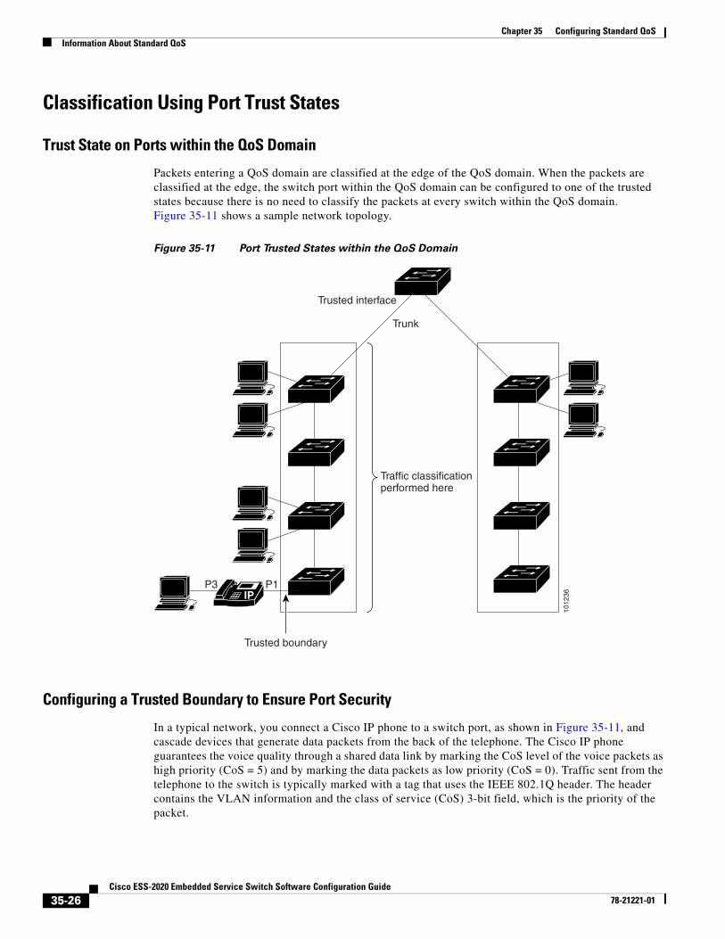
Packets entering a QoS domain are classified at the edge of the QoS domain. When the packets are classified at the edge, the switch port within the QoS domain can be configured to one of the trusted states because there is no need to classify the packets at every switch within the QoS domain. Figure 35-11 shows a sample network topology.
Figure 35-11 Port Trusted States within the QoS Domain
Configuring a Trusted Boundary to Ensure Port Security
In a typical network, you connect a Cisco IP phone to a switch port, as shown in Figure 35-11, and cascade devices that generate data packets from the back of the telephone. The Cisco IP phone guarantees the voice quality through a shared data link by marking the CoS level of the voice packets as high priority (CoS = 5) and by marking the data packets as low priority (CoS = 0). Traffic sent from the telephone to the switch is typically marked with a tag that uses the IEEE 802.1Q header. The header contains the VLAN information and the class of service (CoS) 3-bit field, which is the priority of the packet.
1012
36
Trunk
Trusted interface
Traffic classificationperformed here
Trusted boundary
IPP1P3
35-26Cisco ESS-2020 Embedded Service Switch Software Configuration Guide
78-21221-01
Chapter 35 Configuring Standard QoSInformation About Standard QoS
For most Cisco IP phone configurations, the traffic sent from the telephone to the switch should be trusted to ensure that voice traffic is properly prioritized over other types of traffic in the network. By using the mls qos trust cos interface configuration command, you configure the switch port to which the telephone is connected to trust the CoS labels of all traffic received on that port. Use the mls qos trust dscp interface configuration command to configure a routed port to which the telephone is connected to trust the DSCP labels of all traffic received on that port.
With the trusted setting, you also can use the trusted boundary feature to prevent misuse of a high-priority queue if a user bypasses the telephone and connects the PC directly to the switch. Without trusted boundary, the CoS labels generated by the PC are trusted by the switch (because of the trusted CoS setting). By contrast, trusted boundary uses CDP to detect the presence of a Cisco IP phone (such as the Cisco IP phone 7910, 7935, 7940, and 7960) on a switch port. If the telephone is not detected, the trusted boundary feature disables the trusted setting on the switch port and prevents misuse of a high-priority queue. Note that the trusted boundary feature is not effective if the PC and Cisco IP phone are connected to a hub that is connected to the switch.
In some situations, you can prevent a PC connected to the Cisco IP phone from taking advantage of a high-priority data queue. You can use the switchport priority extend cos interface configuration command to configure the telephone through the switch CLI to override the priority of the traffic received from the PC.
DSCP Transparency Mode
The switch supports the DSCP transparency feature. It affects only the DSCP field of a packet at egress. By default, DSCP transparency is disabled. The switch modifies the DSCP field in an incoming packet, and the DSCP field in the outgoing packet is based on the quality of service (QoS) configuration, including the port trust setting, policing and marking, and the DSCP-to-DSCP mutation map.
If DSCP transparency is enabled by using the no mls qos rewrite ip dscp command, the switch does not modify the DSCP field in the incoming packet, and the DSCP field in the outgoing packet is the same as that in the incoming packet.
Note Enabling DSCP transparency does not affect the port trust settings on IEEE 802.1Q tunneling ports.
Regardless of the DSCP transparency configuration, the switch modifies the internal DSCP value of the packet, which the switch uses to generate a class of service (CoS) value that represents the priority of the traffic. The switch also uses the internal DSCP value to select an egress queue and threshold.
DSCP Trust State on a Port Bordering Another QoS Domain
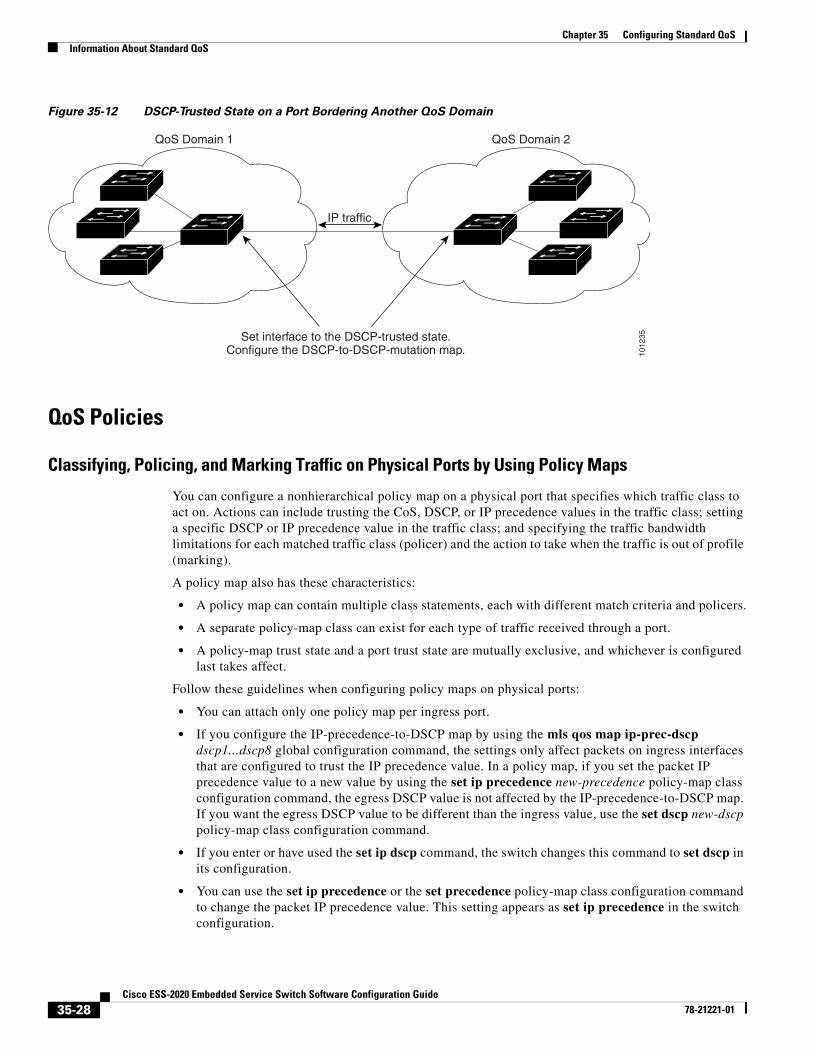
If you are administering two separate QoS domains between which you want to implement QoS features for IP traffic, you can configure the switch ports bordering the domains to a DSCP-trusted state as shown in Figure 35-12. Then the receiving port accepts the DSCP-trusted value and avoids the classification stage of QoS. If the two domains use different DSCP values, you can configure the DSCP-to-DSCP-mutation map to translate a set of DSCP values to match the definition in the other domain.
35-27Cisco ESS-2020 Embedded Service Switch Software Configuration Guide
78-21221-01
Chapter 35 Configuring Standard QoSInformation About Standard QoS
Figure 35-12 DSCP-Trusted State on a Port Bordering Another QoS Domain
QoS Policies
Classifying, Policing, and Marking Traffic on Physical Ports by Using Policy Maps
You can configure a nonhierarchical policy map on a physical port that specifies which traffic class to act on. Actions can include trusting the CoS, DSCP, or IP precedence values in the traffic class; setting a specific DSCP or IP precedence value in the traffic class; and specifying the traffic bandwidth limitations for each matched traffic class (policer) and the action to take when the traffic is out of profile (marking).
A policy map also has these characteristics:
• A policy map can contain multiple class statements, each with different match criteria and policers.
• A separate policy-map class can exist for each type of traffic received through a port.
• A policy-map trust state and a port trust state are mutually exclusive, and whichever is configured last takes affect.
Follow these guidelines when configuring policy maps on physical ports:
• You can attach only one policy map per ingress port.
• If you configure the IP-precedence-to-DSCP map by using the mls qos map ip-prec-dscp dscp1...dscp8 global configuration command, the settings only affect packets on ingress interfaces that are configured to trust the IP precedence value. In a policy map, if you set the packet IP precedence value to a new value by using the set ip precedence new-precedence policy-map class configuration command, the egress DSCP value is not affected by the IP-precedence-to-DSCP map. If you want the egress DSCP value to be different than the ingress value, use the set dscp new-dscp policy-map class configuration command.
• If you enter or have used the set ip dscp command, the switch changes this command to set dscp in its configuration.
• You can use the set ip precedence or the set precedence policy-map class configuration command to change the packet IP precedence value. This setting appears as set ip precedence in the switch configuration.
1012
35
QoS Domain 1 QoS Domain 2
Set interface to the DSCP-trusted state.Configure the DSCP-to-DSCP-mutation map.
IP traffic
35-28Cisco ESS-2020 Embedded Service Switch Software Configuration Guide
78-21221-01
Chapter 35 Configuring Standard QoSInformation About Standard QoS
• You can configure a separate second-level policy map for each class defined for the port. The second-level policy map specifies the police action to take for each traffic class. For information on configuring a hierarchical policy map, see Classifying, Policing, and Marking Traffic on SVIs by Using Hierarchical Policy Maps, page 35-29.
• A policy map and a port trust state can both run on a physical interface. The policy map is applied before the port trust state.
Classifying, Policing, and Marking Traffic on SVIs by Using Hierarchical Policy Maps
You can configure hierarchical policy maps on SVIs, but not on other types of interfaces. Hierarchical policing combines the VLAN- and interface-level policy maps to create a single policy map.
On an SVI, the VLAN-level policy map specifies which traffic class to act on. Actions can include trusting the CoS, DSCP, or IP precedence values or setting a specific DSCP or IP precedence value in the traffic class. Use the interface-level policy map to specify the physical ports that are affected by individual policers.
Follow these guidelines when configuring hierarchical policy maps:
• Before configuring a hierarchical policy map, you must enable VLAN-based QoS on the physical ports that are to be specified at the interface level of the policy map.
• You can attach only one policy map per ingress port or SVI.
• A policy map can contain multiple class statements, each with different match criteria and actions.
• A separate policy-map class can exist for each type of traffic received on the SVI.
• A policy-map and a port trust state can both run on a physical interface. The policy-map is applied before the port trust state.
• If you configure the IP-precedence-to-DSCP map by using the mls qos map ip-prec-dscp dscp1...dscp8 global configuration command, the settings only affect packets on ingress interfaces that are configured to trust the IP precedence value. In a policy map, if you set the packet IP precedence value to a new value by using the set ip precedence new-precedence policy-map class configuration command, the egress DSCP value is not affected by the IP-precedence-to-DSCP map. If you want the egress DSCP value to be different than the ingress value, use the set dscp new-dscp policy-map class configuration command.
• If you enter or have used the set ip dscp command, the switch changes this command to set dscp in its configuration. If you enter the set ip dscp command, this setting appears as set dscp in the switch configuration.
• You can use the set ip precedence or the set precedence policy-map class configuration command to change the packet IP precedence value. This setting appears as set ip precedence in the switch configuration.
• If VLAN-based QoS is enabled, the hierarchical policy map supersedes the previously configured port-based policy map.
• The hierarchical policy map is attached to the SVI and affects all traffic belonging to the VLAN. The actions specified in the VLAN-level policy map affect the traffic belonging to the SVI. The police action on the port-level policy map affects the ingress traffic on the affected physical interfaces.
• When configuring a hierarchical policy map on trunk ports, the VLAN ranges must not overlap. If the ranges overlap, the actions specified in the policy map affect the incoming and outgoing traffic on the overlapped VLANs.
• Aggregate policers are not supported in hierarchical policy maps.
35-29Cisco ESS-2020 Embedded Service Switch Software Configuration Guide
78-21221-01
Chapter 35 Configuring Standard QoSInformation About Standard QoS
• When VLAN-based QoS is enabled, the switch supports VLAN-based features, such as the VLAN map.
• You can configure a hierarchical policy map only on the primary VLAN of a private VLAN.
DSCP MapsFor default DSCP mapping, see “Default Mapping Table Settings” section on page 35-8.
DSCP-to-DSCP-Mutation Map
If two QoS domains have different DSCP definitions, use the DSCP-to-DSCP-mutation map to translate one set of DSCP values to match the definition of another domain. You apply the DSCP-to-DSCP-mutation map to the receiving port (ingress mutation) at the boundary of a QoS administrative domain.
With ingress mutation, the new DSCP value overwrites the one in the packet, and QoS treats the packet with this new value. The switch sends the packet out the port with the new DSCP value.
You can configure multiple DSCP-to-DSCP-mutation maps on an ingress port. The default DSCP-to-DSCP-mutation map is a null map, which maps an incoming DSCP value to the same DSCP value.
Ingress Queue CharacteristicsDepending on the complexity of your network and your QoS solution, you might need to perform all of the tasks in the next sections. You will need to make decisions about these characteristics:
• Which packets are assigned (by DSCP or CoS value) to each queue?
• What drop percentage thresholds apply to each queue, and which CoS or DSCP values map to each threshold?
• How much of the available buffer space is allocated between the queues?
• How much of the available bandwidth is allocated between the queues?
• Is there traffic (such as voice) that should be given high priority?
Ingress Priority Queue
You should use the priority queue only for traffic that needs to be expedited (for example, voice traffic, which needs minimum delay and jitter).
The priority queue is guaranteed part of the bandwidth to reduce the delay and jitter under heavy network traffic on an oversubscribed ring (when there is more traffic than the backplane can carry, and the queues are full and dropping frames).
SRR services the priority queue for its configured weight as specified by the bandwidth keyword in the mls qos srr-queue input priority-queue queue-id bandwidth weight global configuration command. Then, SRR shares the remaining bandwidth with both ingress queues and services them as specified by the weights configured with the mls qos srr-queue input bandwidth weight1 weight2 global configuration command.
35-30Cisco ESS-2020 Embedded Service Switch Software Configuration Guide
78-21221-01
Chapter 35 Configuring Standard QoSInformation About Standard QoS
Egress Queue CharacteristicsDepending on the complexity of your network and your QoS solution, you might need to perform all of the tasks in the next sections. You will need to make decisions about these characteristics:
• Which packets are mapped by DSCP or CoS value to each queue and threshold ID?
• What drop percentage thresholds apply to the queue-set (four egress queues per port), and how much reserved and maximum memory is needed for the traffic type?
• How much of the fixed buffer space is allocated to the queue-set?
• Does the bandwidth of the port need to be rate limited?
• How often should the egress queues be serviced and which technique (shaped, shared, or both) should be used?
Egress Queue Configuration Guidelines
Follow these guidelines when the expedite queue is enabled or the egress queues are serviced based on their SRR weights:
• If the egress expedite queue is enabled, it overrides the SRR shaped and shared weights for queue 1.
• If the egress expedite queue is disabled and the SRR shaped and shared weights are configured, the shaped mode overrides the shared mode for queue 1, and SRR services this queue in shaped mode.
• If the egress expedite queue is disabled and the SRR shaped weights are not configured, SRR services this queue in shared mode.
Allocating Buffer Space to and Setting WTD Thresholds for an Egress Queue-Set
You can guarantee the availability of buffers, set WTD thresholds, and configure the maximum allocation for a queue-set by using the mls qos queue-set output qset-id threshold queue-id drop-threshold1 drop-threshold2 reserved-threshold maximum-threshold global configuration commands.
Each threshold value is a percentage of the queues allocated buffers, which you specify by using the mls qos queue-set output qset-id buffers allocation1 ... allocation4 global configuration command. The queues use WTD to support distinct drop percentages for different traffic classes.
Note The egress queue default settings are suitable for most situations. You should change them only when you have a thorough understanding of the egress queues and if these settings do not meet your QoS solution.
35-31Cisco ESS-2020 Embedded Service Switch Software Configuration Guide
78-21221-01
Chapter 35 Configuring Standard QoSHow to Configure Standard QoS
How to Configure Standard QoS
Enabling QoS Globally
Enabling VLAN-Based QoS on Physical PortsBy default, VLAN-based QoS is disabled on all physical switch ports. The switch applies QoS, including class maps and policy maps, only on a physical-port basis. You can enable VLAN-based QoS on a switch port.
This procedure is required on physical ports that are specified in the interface level of a hierarchical policy map on an SVI.
Configuring Classification Using Port Trust StatesThese sections describe how to classify incoming traffic by using port trust states. Depending on your network configuration, you must perform one or more of these tasks or one or more of the tasks in the “Configuring a QoS Policy” section on page 35-36:
• Configuring the Trust State on Ports Within the QoS Domain, page 35-33
• Configuring the CoS Value for an Interface, page 35-33
• Configuring a Trusted Boundary to Ensure Port Security, page 35-34
• Enabling DSCP Transparency Mode, page 35-34
• Configuring the DSCP Trust State on a Port Bordering Another QoS Domain, page 35-35
Command Purpose
Step 1 configure terminal Enters global configuration mode.
Step 2 mls qos Enables QoS globally.
Step 3 end Returns to privileged EXEC mode.
Command Purpose
Step 1 configure terminal Enters global configuration mode.
Step 2 interface interface-id Specifies the physical port, and enters interface configuration mode.
Step 3 mls qos vlan-based Enables VLAN-based QoS on the port.
Step 4 end Returns to privileged EXEC mode.
35-32Cisco ESS-2020 Embedded Service Switch Software Configuration Guide
78-21221-01
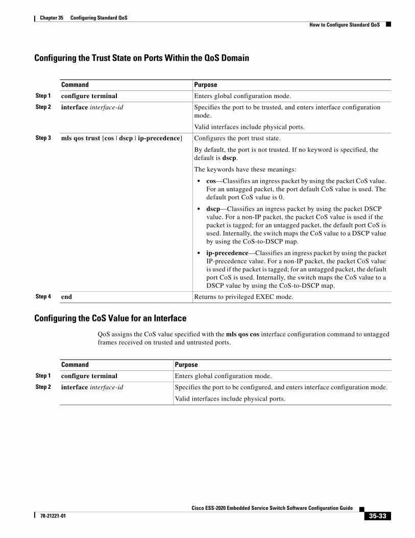
Chapter 35 Configuring Standard QoSHow to Configure Standard QoS
Configuring the Trust State on Ports Within the QoS Domain
Configuring the CoS Value for an Interface
QoS assigns the CoS value specified with the mls qos cos interface configuration command to untagged frames received on trusted and untrusted ports.
Command Purpose
Step 1 configure terminal Enters global configuration mode.
Step 2 interface interface-id Specifies the port to be trusted, and enters interface configuration mode.
Valid interfaces include physical ports.
Step 3 mls qos trust [cos | dscp | ip-precedence] Configures the port trust state.
By default, the port is not trusted. If no keyword is specified, the default is dscp.
The keywords have these meanings:
• cos—Classifies an ingress packet by using the packet CoS value. For an untagged packet, the port default CoS value is used. The default port CoS value is 0.
• dscp—Classifies an ingress packet by using the packet DSCP value. For a non-IP packet, the packet CoS value is used if the packet is tagged; for an untagged packet, the default port CoS is used. Internally, the switch maps the CoS value to a DSCP value by using the CoS-to-DSCP map.
• ip-precedence—Classifies an ingress packet by using the packet IP-precedence value. For a non-IP packet, the packet CoS value is used if the packet is tagged; for an untagged packet, the default port CoS is used. Internally, the switch maps the CoS value to a DSCP value by using the CoS-to-DSCP map.
Step 4 end Returns to privileged EXEC mode.
Command Purpose
Step 1 configure terminal Enters global configuration mode.
Step 2 interface interface-id Specifies the port to be configured, and enters interface configuration mode.
Valid interfaces include physical ports.
35-33Cisco ESS-2020 Embedded Service Switch Software Configuration Guide
78-21221-01
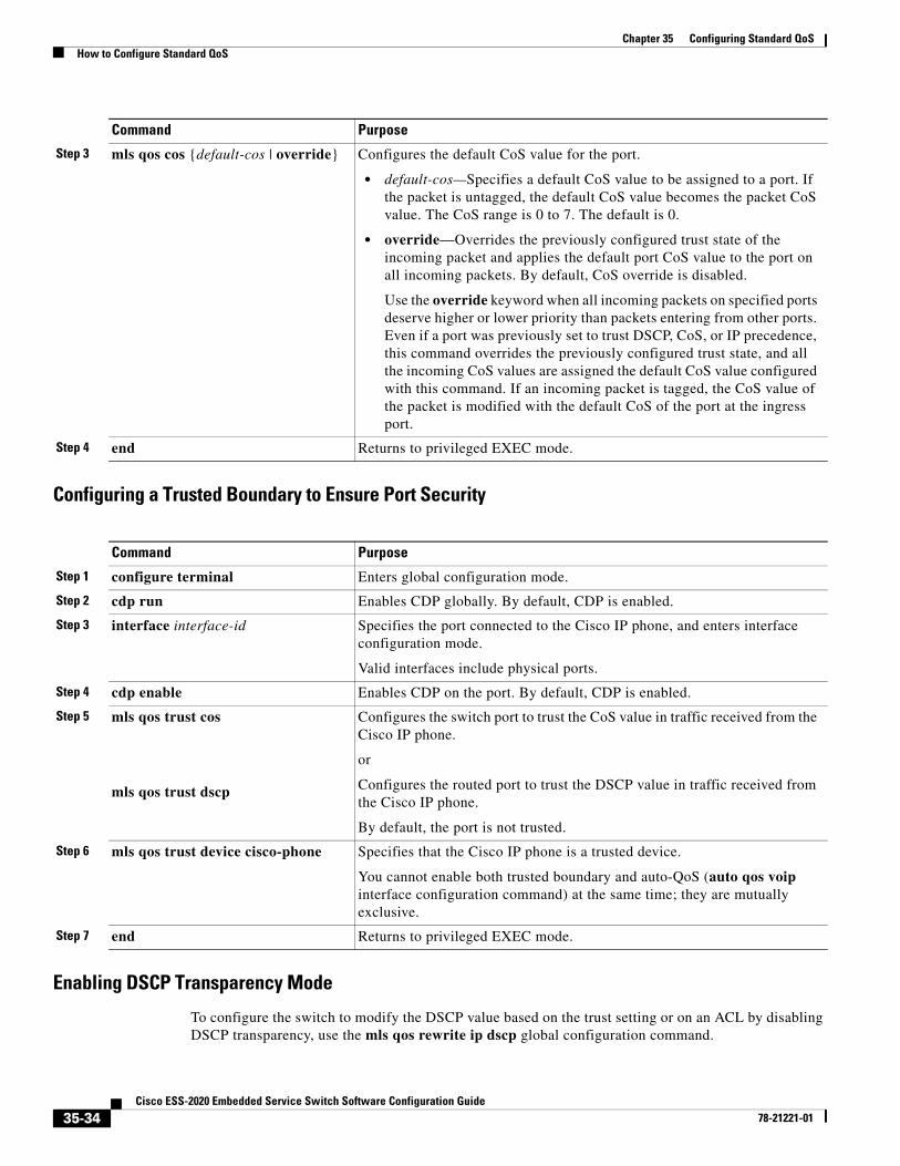
Chapter 35 Configuring Standard QoSHow to Configure Standard QoS
Configuring a Trusted Boundary to Ensure Port Security
Enabling DSCP Transparency Mode
To configure the switch to modify the DSCP value based on the trust setting or on an ACL by disabling DSCP transparency, use the mls qos rewrite ip dscp global configuration command.
Step 3 mls qos cos {default-cos | override} Configures the default CoS value for the port.
• default-cos—Specifies a default CoS value to be assigned to a port. If the packet is untagged, the default CoS value becomes the packet CoS value. The CoS range is 0 to 7. The default is 0.
• override—Overrides the previously configured trust state of the incoming packet and applies the default port CoS value to the port on all incoming packets. By default, CoS override is disabled.
Use the override keyword when all incoming packets on specified ports deserve higher or lower priority than packets entering from other ports. Even if a port was previously set to trust DSCP, CoS, or IP precedence, this command overrides the previously configured trust state, and all the incoming CoS values are assigned the default CoS value configured with this command. If an incoming packet is tagged, the CoS value of the packet is modified with the default CoS of the port at the ingress port.
Step 4 end Returns to privileged EXEC mode.
Command Purpose
Step 1 configure terminal Enters global configuration mode.
Step 2 cdp run Enables CDP globally. By default, CDP is enabled.
Step 3 interface interface-id Specifies the port connected to the Cisco IP phone, and enters interface configuration mode.
Valid interfaces include physical ports.
Step 4 cdp enable Enables CDP on the port. By default, CDP is enabled.
Step 5 mls qos trust cos
mls qos trust dscp
Configures the switch port to trust the CoS value in traffic received from the Cisco IP phone.
or
Configures the routed port to trust the DSCP value in traffic received from the Cisco IP phone.
By default, the port is not trusted.
Step 6 mls qos trust device cisco-phone Specifies that the Cisco IP phone is a trusted device.
You cannot enable both trusted boundary and auto-QoS (auto qos voip interface configuration command) at the same time; they are mutually exclusive.
Step 7 end Returns to privileged EXEC mode.
Command Purpose
35-34Cisco ESS-2020 Embedded Service Switch Software Configuration Guide
78-21221-01
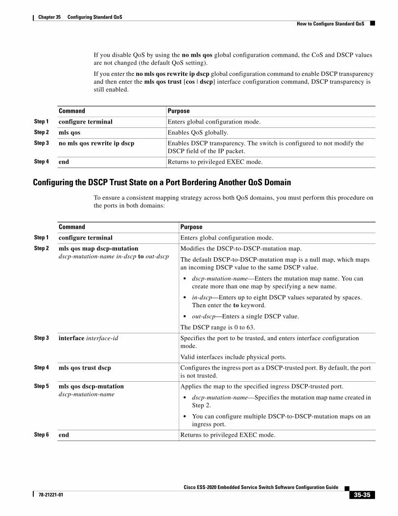
Chapter 35 Configuring Standard QoSHow to Configure Standard QoS
If you disable QoS by using the no mls qos global configuration command, the CoS and DSCP values are not changed (the default QoS setting).
If you enter the no mls qos rewrite ip dscp global configuration command to enable DSCP transparency and then enter the mls qos trust [cos | dscp] interface configuration command, DSCP transparency is still enabled.
Configuring the DSCP Trust State on a Port Bordering Another QoS Domain
To ensure a consistent mapping strategy across both QoS domains, you must perform this procedure on the ports in both domains:
Command Purpose
Step 1 configure terminal Enters global configuration mode.
Step 2 mls qos Enables QoS globally.
Step 3 no mls qos rewrite ip dscp Enables DSCP transparency. The switch is configured to not modify the DSCP field of the IP packet.
Step 4 end Returns to privileged EXEC mode.
Command Purpose
Step 1 configure terminal Enters global configuration mode.
Step 2 mls qos map dscp-mutation dscp-mutation-name in-dscp to out-dscp
Modifies the DSCP-to-DSCP-mutation map.
The default DSCP-to-DSCP-mutation map is a null map, which maps an incoming DSCP value to the same DSCP value.
• dscp-mutation-name—Enters the mutation map name. You can create more than one map by specifying a new name.
• in-dscp—Enters up to eight DSCP values separated by spaces. Then enter the to keyword.
• out-dscp—Enters a single DSCP value.
The DSCP range is 0 to 63.
Step 3 interface interface-id Specifies the port to be trusted, and enters interface configuration mode.
Valid interfaces include physical ports.
Step 4 mls qos trust dscp Configures the ingress port as a DSCP-trusted port. By default, the port is not trusted.
Step 5 mls qos dscp-mutation dscp-mutation-name
Applies the map to the specified ingress DSCP-trusted port.
• dscp-mutation-name—Specifies the mutation map name created in Step 2.
• You can configure multiple DSCP-to-DSCP-mutation maps on an ingress port.
Step 6 end Returns to privileged EXEC mode.
35-35Cisco ESS-2020 Embedded Service Switch Software Configuration Guide
78-21221-01
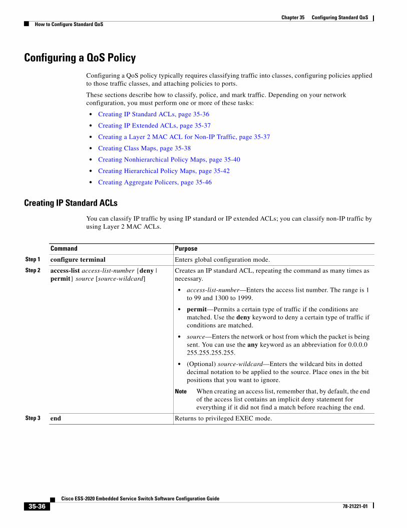
Chapter 35 Configuring Standard QoSHow to Configure Standard QoS
Configuring a QoS PolicyConfiguring a QoS policy typically requires classifying traffic into classes, configuring policies applied to those traffic classes, and attaching policies to ports.
These sections describe how to classify, police, and mark traffic. Depending on your network configuration, you must perform one or more of these tasks:
• Creating IP Standard ACLs, page 35-36
• Creating IP Extended ACLs, page 35-37
• Creating a Layer 2 MAC ACL for Non-IP Traffic, page 35-37
• Creating Class Maps, page 35-38
• Creating Nonhierarchical Policy Maps, page 35-40
• Creating Hierarchical Policy Maps, page 35-42
• Creating Aggregate Policers, page 35-46
Creating IP Standard ACLs
You can classify IP traffic by using IP standard or IP extended ACLs; you can classify non-IP traffic by using Layer 2 MAC ACLs.
Command Purpose
Step 1 configure terminal Enters global configuration mode.
Step 2 access-list access-list-number {deny | permit} source [source-wildcard]
Creates an IP standard ACL, repeating the command as many times as necessary.
• access-list-number—Enters the access list number. The range is 1 to 99 and 1300 to 1999.
• permit—Permits a certain type of traffic if the conditions are matched. Use the deny keyword to deny a certain type of traffic if conditions are matched.
• source—Enters the network or host from which the packet is being sent. You can use the any keyword as an abbreviation for 0.0.0.0 255.255.255.255.
• (Optional) source-wildcard—Enters the wildcard bits in dotted decimal notation to be applied to the source. Place ones in the bit positions that you want to ignore.
Note When creating an access list, remember that, by default, the end of the access list contains an implicit deny statement for everything if it did not find a match before reaching the end.
Step 3 end Returns to privileged EXEC mode.
35-36Cisco ESS-2020 Embedded Service Switch Software Configuration Guide
78-21221-01
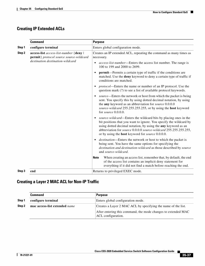
Chapter 35 Configuring Standard QoSHow to Configure Standard QoS
Creating IP Extended ACLs
Creating a Layer 2 MAC ACL for Non-IP Traffic
Command Purpose
Step 1 configure terminal Enters global configuration mode.
Step 2 access-list access-list-number {deny | permit} protocol source source-wildcard destination destination-wildcard
Creates an IP extended ACL, repeating the command as many times as necessary.
• access-list-number—Enters the access list number. The range is 100 to 199 and 2000 to 2699.
• permit—Permits a certain type of traffic if the conditions are matched. Use the deny keyword to deny a certain type of traffic if conditions are matched.
• protocol—Enters the name or number of an IP protocol. Use the question mark (?) to see a list of available protocol keywords.
• source—Enters the network or host from which the packet is being sent. You specify this by using dotted decimal notation, by using the any keyword as an abbreviation for source 0.0.0.0 source-wildcard 255.255.255.255, or by using the host keyword for source 0.0.0.0.
• source-wildcard—Enters the wildcard bits by placing ones in the bit positions that you want to ignore. You specify the wildcard by using dotted decimal notation, by using the any keyword as an abbreviation for source 0.0.0.0 source-wildcard 255.255.255.255, or by using the host keyword for source 0.0.0.0.
• destination—Enters the network or host to which the packet is being sent. You have the same options for specifying the destination and destination-wildcard as those described by source and source-wildcard.
Note When creating an access list, remember that, by default, the end of the access list contains an implicit deny statement for everything if it did not find a match before reaching the end.
Step 3 end Returns to privileged EXEC mode.
Command Purpose
Step 1 configure terminal Enters global configuration mode.
Step 2 mac access-list extended name Creates a Layer 2 MAC ACL by specifying the name of the list.
After entering this command, the mode changes to extended MAC ACL configuration.
35-37Cisco ESS-2020 Embedded Service Switch Software Configuration Guide
78-21221-01
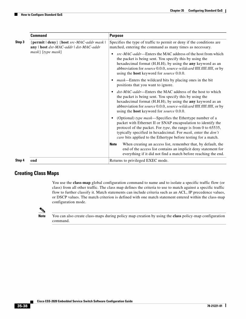
Chapter 35 Configuring Standard QoSHow to Configure Standard QoS
Creating Class Maps
You use the class-map global configuration command to name and to isolate a specific traffic flow (or class) from all other traffic. The class map defines the criteria to use to match against a specific traffic flow to further classify it. Match statements can include criteria such as an ACL, IP precedence values, or DSCP values. The match criterion is defined with one match statement entered within the class-map configuration mode.
Note You can also create class-maps during policy map creation by using the class policy-map configuration command.
Step 3 {permit | deny} {host src-MAC-addr mask | any | host dst-MAC-addr | dst-MAC-addr mask} [type mask]
Specifies the type of traffic to permit or deny if the conditions are matched, entering the command as many times as necessary.
• src-MAC-addr—Enters the MAC address of the host from which the packet is being sent. You specify this by using the hexadecimal format (H.H.H), by using the any keyword as an abbreviation for source 0.0.0, source-wildcard ffff.ffff.ffff, or by using the host keyword for source 0.0.0.
• mask—Enters the wildcard bits by placing ones in the bit positions that you want to ignore.
• dst-MAC-addr—Enters the MAC address of the host to which the packet is being sent. You specify this by using the hexadecimal format (H.H.H), by using the any keyword as an abbreviation for source 0.0.0, source-wildcard ffff.ffff.ffff, or by using the host keyword for source 0.0.0.
• (Optional) type mask—Specifies the Ethertype number of a packet with Ethernet II or SNAP encapsulation to identify the protocol of the packet. For type, the range is from 0 to 65535, typically specified in hexadecimal. For mask, enter the don’t care bits applied to the Ethertype before testing for a match.
Note When creating an access list, remember that, by default, the end of the access list contains an implicit deny statement for everything if it did not find a match before reaching the end.
Step 4 end Returns to privileged EXEC mode.
Command Purpose
35-38Cisco ESS-2020 Embedded Service Switch Software Configuration Guide
78-21221-01
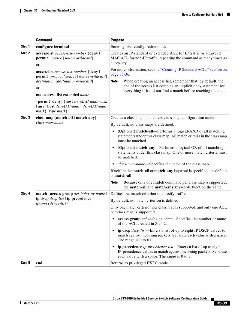
Chapter 35 Configuring Standard QoSHow to Configure Standard QoS
Command Purpose
Step 1 configure terminal Enters global configuration mode.
Step 2 access-list access-list-number {deny | permit} source [source-wildcard]
or
access-list access-list-number {deny | permit} protocol source [source-wildcard] destination [destination-wildcard]
or
mac access-list extended name
{permit | deny} {host src-MAC-addr mask | any | host dst-MAC-addr | dst-MAC-addr mask} [type mask]
Creates an IP standard or extended ACL for IP traffic or a Layer 2 MAC ACL for non-IP traffic, repeating the command as many times as necessary.
For more information, see the “Creating IP Standard ACLs” section on page 35-36.
Note When creating an access list, remember that, by default, the end of the access list contains an implicit deny statement for everything if it did not find a match before reaching the end.
Step 3 class-map [match-all | match-any] class-map-name
Creates a class map, and enters class-map configuration mode.
By default, no class maps are defined.
• (Optional) match-all—Performs a logical-AND of all matching statements under this class map. All match criteria in the class map must be matched.
• (Optional) match-any—Performs a logical-OR of all matching statements under this class map. One or more match criteria must be matched.
• class-map-name—Specifies the name of the class map.
If neither the match-all or match-any keyword is specified, the default is match-all.
Note Because only one match command per class map is supported, the match-all and match-any keywords function the same.
Step 4 match {access-group acl-index-or-name | ip dscp dscp-list | ip precedence ip-precedence-list}
Defines the match criterion to classify traffic.
By default, no match criterion is defined.
Only one match criterion per class map is supported, and only one ACL per class map is supported.
• access-group acl-index-or-name—Specifies the number or name of the ACL created in Step 2.
• ip dscp dscp-list—Enters a list of up to eight IP DSCP values to match against incoming packets. Separate each value with a space. The range is 0 to 63.
• ip precedence ip-precedence-list—Enters a list of up to eight IP-precedence values to match against incoming packets. Separate each value with a space. The range is 0 to 7.
Step 5 end Returns to privileged EXEC mode.
35-39Cisco ESS-2020 Embedded Service Switch Software Configuration Guide
78-21221-01
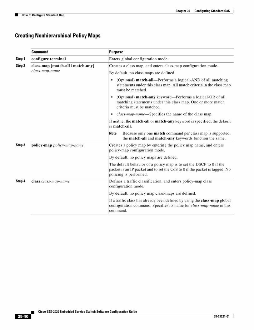
Chapter 35 Configuring Standard QoSHow to Configure Standard QoS
Creating Nonhierarchical Policy Maps
Command Purpose
Step 1 configure terminal Enters global configuration mode.
Step 2 class-map [match-all | match-any] class-map-name
Creates a class map, and enters class-map configuration mode.
By default, no class maps are defined.
• (Optional) match-all—Performs a logical-AND of all matching statements under this class map. All match criteria in the class map must be matched.
• (Optional) match-any keyword—Performs a logical-OR of all matching statements under this class map. One or more match criteria must be matched.
• class-map-name—Specifies the name of the class map.
If neither the match-all or match-any keyword is specified, the default is match-all.
Note Because only one match command per class map is supported, the match-all and match-any keywords function the same.
Step 3 policy-map policy-map-name Creates a policy map by entering the policy map name, and enters policy-map configuration mode.
By default, no policy maps are defined.
The default behavior of a policy map is to set the DSCP to 0 if the packet is an IP packet and to set the CoS to 0 if the packet is tagged. No policing is performed.
Step 4 class class-map-name Defines a traffic classification, and enters policy-map class configuration mode.
By default, no policy map class-maps are defined.
If a traffic class has already been defined by using the class-map global configuration command, Specifies its name for class-map-name in this command.
35-40Cisco ESS-2020 Embedded Service Switch Software Configuration Guide
78-21221-01
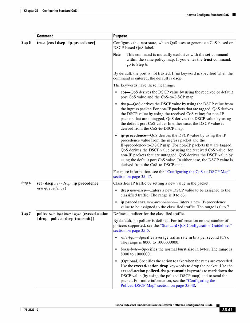
Chapter 35 Configuring Standard QoSHow to Configure Standard QoS
Step 5 trust [cos | dscp | ip-precedence] Configures the trust state, which QoS uses to generate a CoS-based or DSCP-based QoS label.
Note This command is mutually exclusive with the set command within the same policy map. If you enter the trust command, go to Step 6.
By default, the port is not trusted. If no keyword is specified when the command is entered, the default is dscp.
The keywords have these meanings:
• cos—QoS derives the DSCP value by using the received or default port CoS value and the CoS-to-DSCP map.
• dscp—QoS derives the DSCP value by using the DSCP value from the ingress packet. For non-IP packets that are tagged, QoS derives the DSCP value by using the received CoS value; for non-IP packets that are untagged, QoS derives the DSCP value by using the default port CoS value. In either case, the DSCP value is derived from the CoS-to-DSCP map.
• ip-precedence—QoS derives the DSCP value by using the IP precedence value from the ingress packet and the IP-precedence-to-DSCP map. For non-IP packets that are tagged, QoS derives the DSCP value by using the received CoS value; for non-IP packets that are untagged, QoS derives the DSCP value by using the default port CoS value. In either case, the DSCP value is derived from the CoS-to-DSCP map.
For more information, see the “Configuring the CoS-to-DSCP Map” section on page 35-47.
Step 6 set {dscp new-dscp | ip precedence new-precedence}
Classifies IP traffic by setting a new value in the packet.
• dscp new-dscp—Enters a new DSCP value to be assigned to the classified traffic. The range is 0 to 63.
• ip precedence new-precedence—Enters a new IP-precedence value to be assigned to the classified traffic. The range is 0 to 7.
Step 7 police rate-bps burst-byte [exceed-action {drop | policed-dscp-transmit}]
Defines a policer for the classified traffic.
By default, no policer is defined. For information on the number of policers supported, see the “Standard QoS Configuration Guidelines” section on page 35-5.
• rate-bps—Specifies average traffic rate in bits per second (b/s). The range is 8000 to 1000000000.
• burst-byte—Specifies the normal burst size in bytes. The range is 8000 to 1000000.
• (Optional) Specifies the action to take when the rates are exceeded. Use the exceed-action drop keywords to drop the packet. Use the exceed-action policed-dscp-transmit keywords to mark down the DSCP value (by using the policed-DSCP map) and to send the packet. For more information, see the “Configuring the Policed-DSCP Map” section on page 35-48.
Command Purpose
35-41Cisco ESS-2020 Embedded Service Switch Software Configuration Guide
78-21221-01
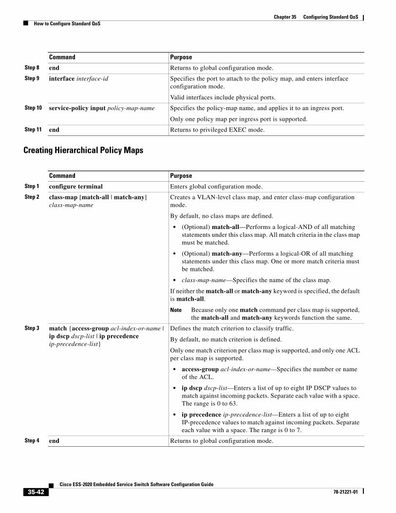
Chapter 35 Configuring Standard QoSHow to Configure Standard QoS
Creating Hierarchical Policy Maps
Step 8 end Returns to global configuration mode.
Step 9 interface interface-id Specifies the port to attach to the policy map, and enters interface configuration mode.
Valid interfaces include physical ports.
Step 10 service-policy input policy-map-name Specifies the policy-map name, and applies it to an ingress port.
Only one policy map per ingress port is supported.
Step 11 end Returns to privileged EXEC mode.
Command Purpose
Step 1 configure terminal Enters global configuration mode.
Step 2 class-map [match-all | match-any] class-map-name
Creates a VLAN-level class map, and enter class-map configuration mode.
By default, no class maps are defined.
• (Optional) match-all—Performs a logical-AND of all matching statements under this class map. All match criteria in the class map must be matched.
• (Optional) match-any—Performs a logical-OR of all matching statements under this class map. One or more match criteria must be matched.
• class-map-name—Specifies the name of the class map.
If neither the match-all or match-any keyword is specified, the default is match-all.
Note Because only one match command per class map is supported, the match-all and match-any keywords function the same.
Step 3 match {access-group acl-index-or-name | ip dscp dscp-list | ip precedence ip-precedence-list}
Defines the match criterion to classify traffic.
By default, no match criterion is defined.
Only one match criterion per class map is supported, and only one ACL per class map is supported.
• access-group acl-index-or-name—Specifies the number or name of the ACL.
• ip dscp dscp-list—Enters a list of up to eight IP DSCP values to match against incoming packets. Separate each value with a space. The range is 0 to 63.
• ip precedence ip-precedence-list—Enters a list of up to eight IP-precedence values to match against incoming packets. Separate each value with a space. The range is 0 to 7.
Step 4 end Returns to global configuration mode.
Command Purpose
35-42Cisco ESS-2020 Embedded Service Switch Software Configuration Guide
78-21221-01
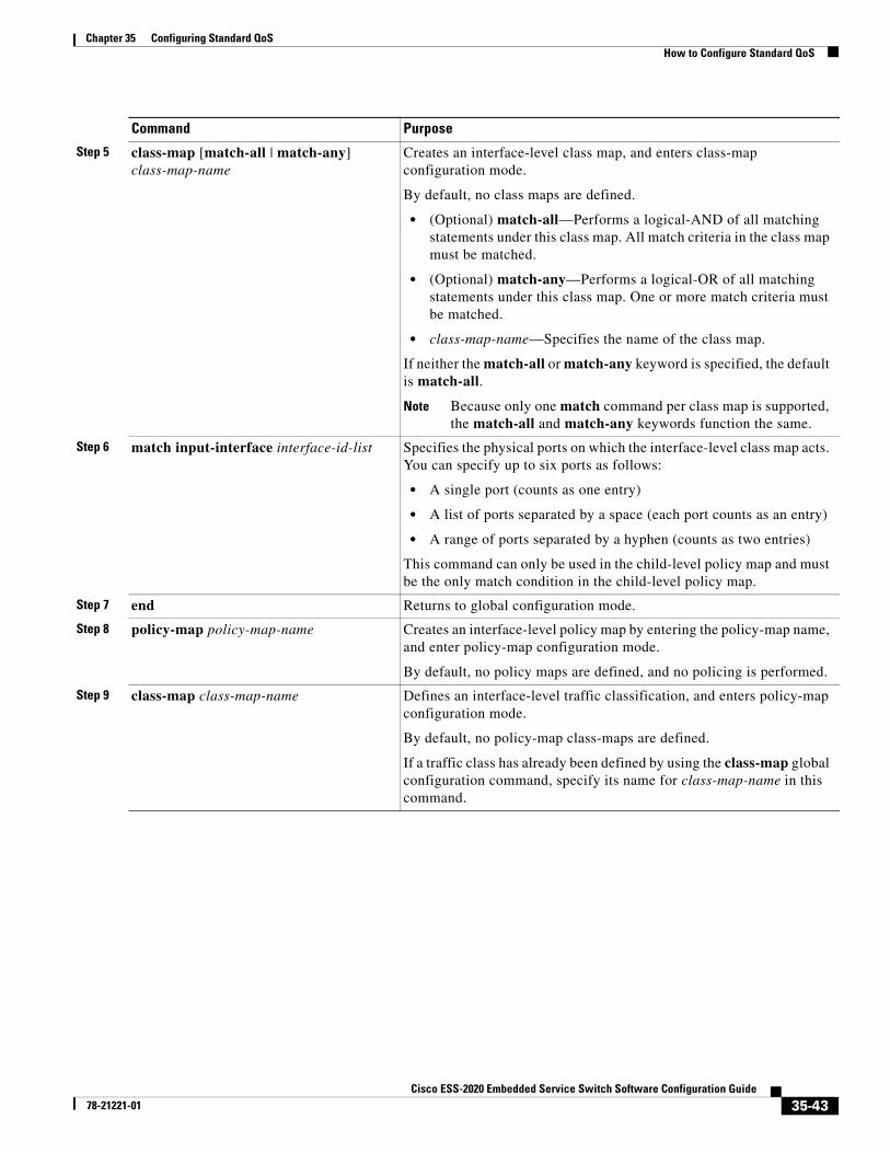
Chapter 35 Configuring Standard QoSHow to Configure Standard QoS
Step 5 class-map [match-all | match-any] class-map-name
Creates an interface-level class map, and enters class-map configuration mode.
By default, no class maps are defined.
• (Optional) match-all—Performs a logical-AND of all matching statements under this class map. All match criteria in the class map must be matched.
• (Optional) match-any—Performs a logical-OR of all matching statements under this class map. One or more match criteria must be matched.
• class-map-name—Specifies the name of the class map.
If neither the match-all or match-any keyword is specified, the default is match-all.
Note Because only one match command per class map is supported, the match-all and match-any keywords function the same.
Step 6 match input-interface interface-id-list Specifies the physical ports on which the interface-level class map acts. You can specify up to six ports as follows:
• A single port (counts as one entry)
• A list of ports separated by a space (each port counts as an entry)
• A range of ports separated by a hyphen (counts as two entries)
This command can only be used in the child-level policy map and must be the only match condition in the child-level policy map.
Step 7 end Returns to global configuration mode.
Step 8 policy-map policy-map-name Creates an interface-level policy map by entering the policy-map name, and enter policy-map configuration mode.
By default, no policy maps are defined, and no policing is performed.
Step 9 class-map class-map-name Defines an interface-level traffic classification, and enters policy-map configuration mode.
By default, no policy-map class-maps are defined.
If a traffic class has already been defined by using the class-map global configuration command, specify its name for class-map-name in this command.
Command Purpose
35-43Cisco ESS-2020 Embedded Service Switch Software Configuration Guide
78-21221-01
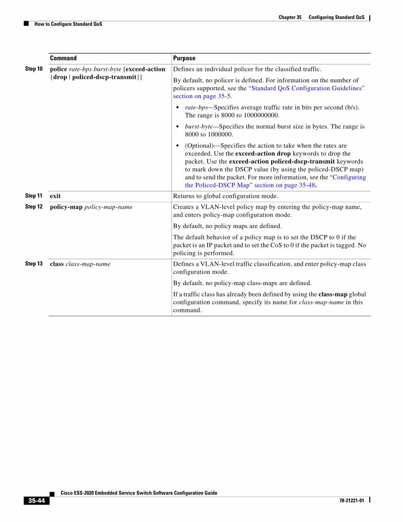
Chapter 35 Configuring Standard QoSHow to Configure Standard QoS
Step 10 police rate-bps burst-byte [exceed-action {drop | policed-dscp-transmit}]
Defines an individual policer for the classified traffic.
By default, no policer is defined. For information on the number of policers supported, see the “Standard QoS Configuration Guidelines” section on page 35-5.
• rate-bps—Specifies average traffic rate in bits per second (b/s). The range is 8000 to 1000000000.
• burst-byte—Specifies the normal burst size in bytes. The range is 8000 to 1000000.
• (Optional)—Specifies the action to take when the rates are exceeded. Use the exceed-action drop keywords to drop the packet. Use the exceed-action policed-dscp-transmit keywords to mark down the DSCP value (by using the policed-DSCP map) and to send the packet. For more information, see the “Configuring the Policed-DSCP Map” section on page 35-48.
Step 11 exit Returns to global configuration mode.
Step 12 policy-map policy-map-name Creates a VLAN-level policy map by entering the policy-map name, and enters policy-map configuration mode.
By default, no policy maps are defined.
The default behavior of a policy map is to set the DSCP to 0 if the packet is an IP packet and to set the CoS to 0 if the packet is tagged. No policing is performed.
Step 13 class class-map-name Defines a VLAN-level traffic classification, and enter policy-map class configuration mode.
By default, no policy-map class-maps are defined.
If a traffic class has already been defined by using the class-map global configuration command, specify its name for class-map-name in this command.
Command Purpose
35-44Cisco ESS-2020 Embedded Service Switch Software Configuration Guide
78-21221-01
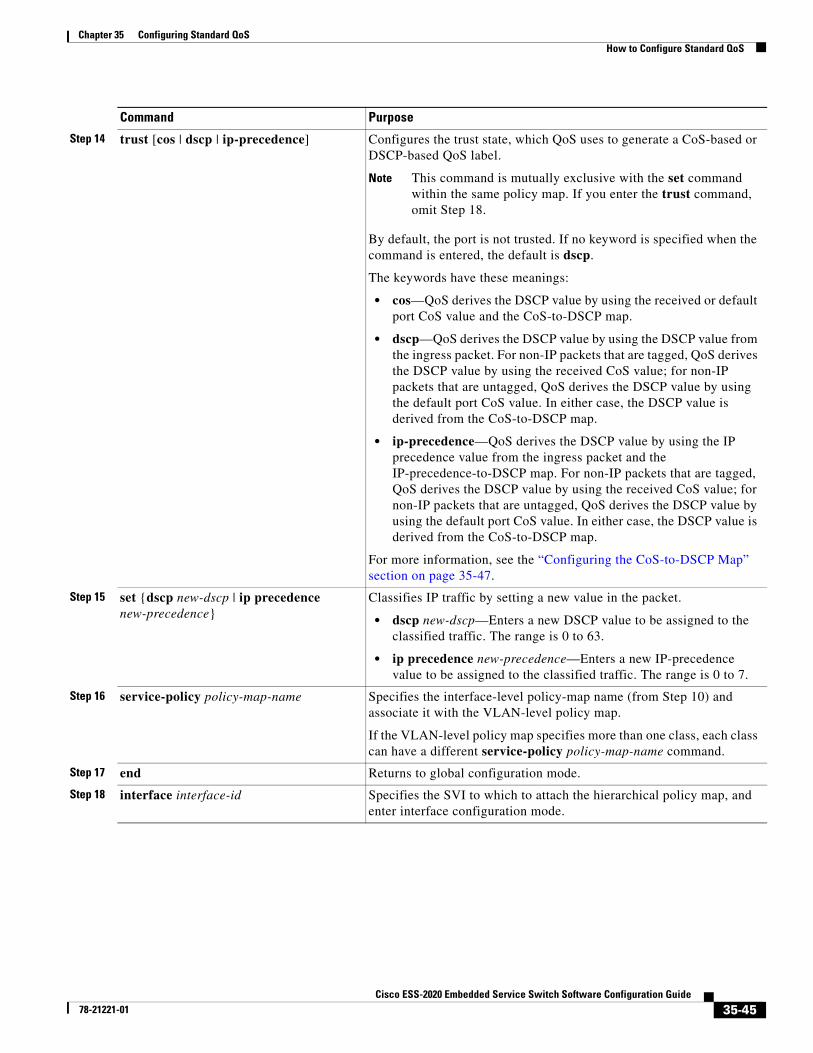
Chapter 35 Configuring Standard QoSHow to Configure Standard QoS
Step 14 trust [cos | dscp | ip-precedence] Configures the trust state, which QoS uses to generate a CoS-based or DSCP-based QoS label.
Note This command is mutually exclusive with the set command within the same policy map. If you enter the trust command, omit Step 18.
By default, the port is not trusted. If no keyword is specified when the command is entered, the default is dscp.
The keywords have these meanings:
• cos—QoS derives the DSCP value by using the received or default port CoS value and the CoS-to-DSCP map.
• dscp—QoS derives the DSCP value by using the DSCP value from the ingress packet. For non-IP packets that are tagged, QoS derives the DSCP value by using the received CoS value; for non-IP packets that are untagged, QoS derives the DSCP value by using the default port CoS value. In either case, the DSCP value is derived from the CoS-to-DSCP map.
• ip-precedence—QoS derives the DSCP value by using the IP precedence value from the ingress packet and the IP-precedence-to-DSCP map. For non-IP packets that are tagged, QoS derives the DSCP value by using the received CoS value; for non-IP packets that are untagged, QoS derives the DSCP value by using the default port CoS value. In either case, the DSCP value is derived from the CoS-to-DSCP map.
For more information, see the “Configuring the CoS-to-DSCP Map” section on page 35-47.
Step 15 set {dscp new-dscp | ip precedence new-precedence}
Classifies IP traffic by setting a new value in the packet.
• dscp new-dscp—Enters a new DSCP value to be assigned to the classified traffic. The range is 0 to 63.
• ip precedence new-precedence—Enters a new IP-precedence value to be assigned to the classified traffic. The range is 0 to 7.
Step 16 service-policy policy-map-name Specifies the interface-level policy-map name (from Step 10) and associate it with the VLAN-level policy map.
If the VLAN-level policy map specifies more than one class, each class can have a different service-policy policy-map-name command.
Step 17 end Returns to global configuration mode.
Step 18 interface interface-id Specifies the SVI to which to attach the hierarchical policy map, and enter interface configuration mode.
Command Purpose
35-45Cisco ESS-2020 Embedded Service Switch Software Configuration Guide
78-21221-01
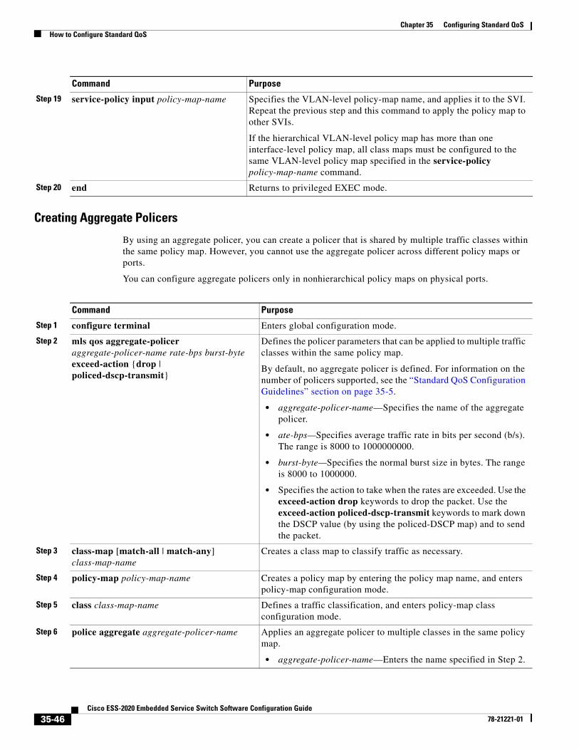
Chapter 35 Configuring Standard QoSHow to Configure Standard QoS
Creating Aggregate Policers
By using an aggregate policer, you can create a policer that is shared by multiple traffic classes within the same policy map. However, you cannot use the aggregate policer across different policy maps or ports.
You can configure aggregate policers only in nonhierarchical policy maps on physical ports.
Step 19 service-policy input policy-map-name Specifies the VLAN-level policy-map name, and applies it to the SVI. Repeat the previous step and this command to apply the policy map to other SVIs.
If the hierarchical VLAN-level policy map has more than one interface-level policy map, all class maps must be configured to the same VLAN-level policy map specified in the service-policy policy-map-name command.
Step 20 end Returns to privileged EXEC mode.
Command Purpose
Command Purpose
Step 1 configure terminal Enters global configuration mode.
Step 2 mls qos aggregate-policer aggregate-policer-name rate-bps burst-byte exceed-action {drop | policed-dscp-transmit}
Defines the policer parameters that can be applied to multiple traffic classes within the same policy map.
By default, no aggregate policer is defined. For information on the number of policers supported, see the “Standard QoS Configuration Guidelines” section on page 35-5.
• aggregate-policer-name—Specifies the name of the aggregate policer.
• ate-bps—Specifies average traffic rate in bits per second (b/s). The range is 8000 to 1000000000.
• burst-byte—Specifies the normal burst size in bytes. The range is 8000 to 1000000.
• Specifies the action to take when the rates are exceeded. Use the exceed-action drop keywords to drop the packet. Use the exceed-action policed-dscp-transmit keywords to mark down the DSCP value (by using the policed-DSCP map) and to send the packet.
Step 3 class-map [match-all | match-any] class-map-name
Creates a class map to classify traffic as necessary.
Step 4 policy-map policy-map-name Creates a policy map by entering the policy map name, and enters policy-map configuration mode.
Step 5 class class-map-name Defines a traffic classification, and enters policy-map class configuration mode.
Step 6 police aggregate aggregate-policer-name Applies an aggregate policer to multiple classes in the same policy map.
• aggregate-policer-name—Enters the name specified in Step 2.
35-46Cisco ESS-2020 Embedded Service Switch Software Configuration Guide
78-21221-01
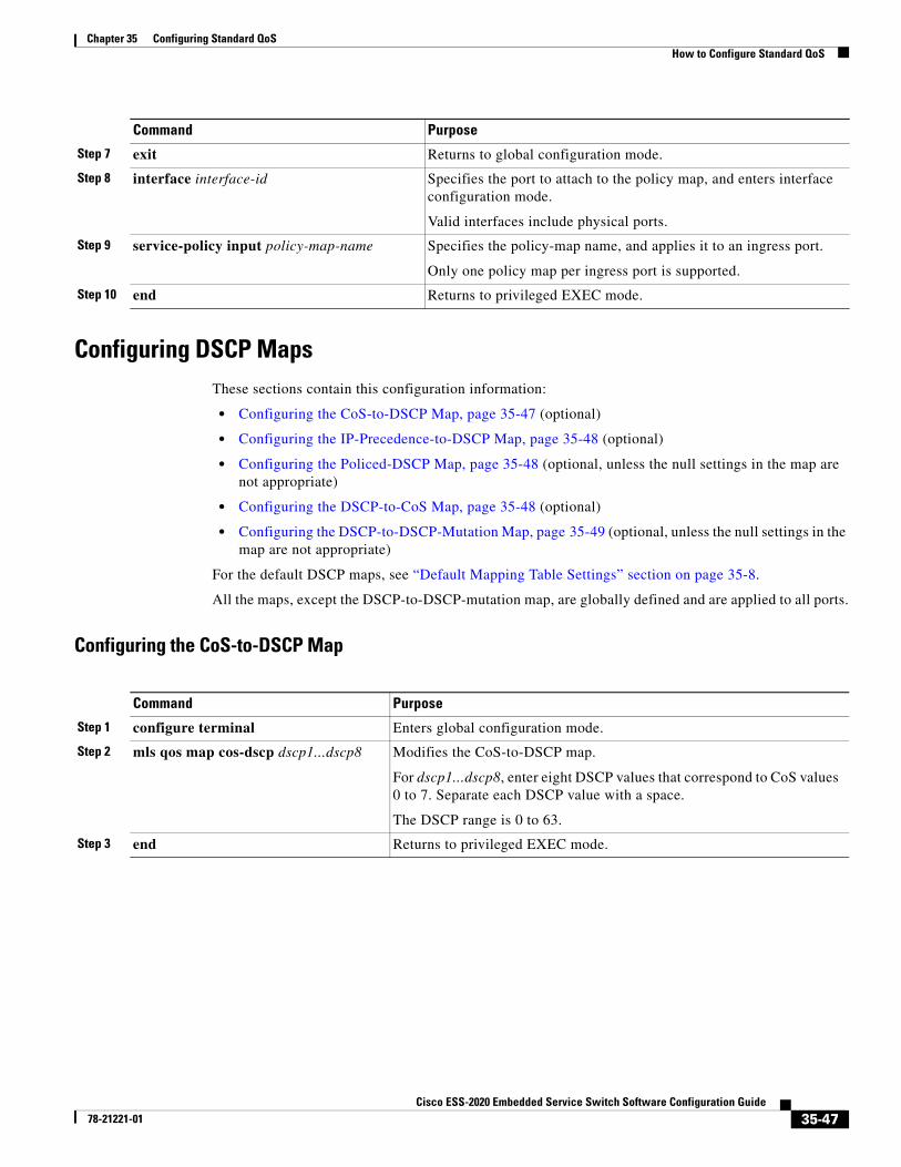
Chapter 35 Configuring Standard QoSHow to Configure Standard QoS
Configuring DSCP MapsThese sections contain this configuration information:
• Configuring the CoS-to-DSCP Map, page 35-47 (optional)
• Configuring the IP-Precedence-to-DSCP Map, page 35-48 (optional)
• Configuring the Policed-DSCP Map, page 35-48 (optional, unless the null settings in the map are not appropriate)
• Configuring the DSCP-to-CoS Map, page 35-48 (optional)
• Configuring the DSCP-to-DSCP-Mutation Map, page 35-49 (optional, unless the null settings in the map are not appropriate)
For the default DSCP maps, see “Default Mapping Table Settings” section on page 35-8.
All the maps, except the DSCP-to-DSCP-mutation map, are globally defined and are applied to all ports.
Configuring the CoS-to-DSCP Map
Step 7 exit Returns to global configuration mode.
Step 8 interface interface-id Specifies the port to attach to the policy map, and enters interface configuration mode.
Valid interfaces include physical ports.
Step 9 service-policy input policy-map-name Specifies the policy-map name, and applies it to an ingress port.
Only one policy map per ingress port is supported.
Step 10 end Returns to privileged EXEC mode.
Command Purpose
Command Purpose
Step 1 configure terminal Enters global configuration mode.
Step 2 mls qos map cos-dscp dscp1...dscp8 Modifies the CoS-to-DSCP map.
For dscp1...dscp8, enter eight DSCP values that correspond to CoS values 0 to 7. Separate each DSCP value with a space.
The DSCP range is 0 to 63.
Step 3 end Returns to privileged EXEC mode.
35-47Cisco ESS-2020 Embedded Service Switch Software Configuration Guide
78-21221-01
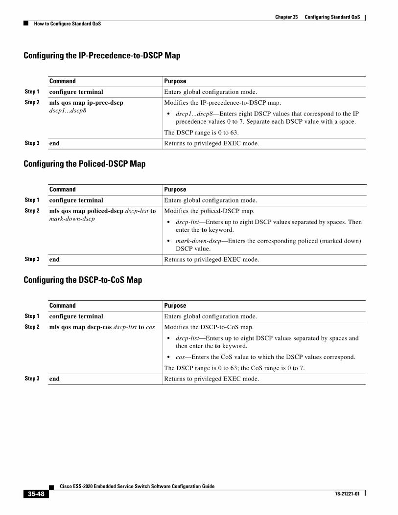
Chapter 35 Configuring Standard QoSHow to Configure Standard QoS
Configuring the IP-Precedence-to-DSCP Map
Configuring the Policed-DSCP Map
Configuring the DSCP-to-CoS Map
Command Purpose
Step 1 configure terminal Enters global configuration mode.
Step 2 mls qos map ip-prec-dscp dscp1...dscp8
Modifies the IP-precedence-to-DSCP map.
• dscp1...dscp8—Enters eight DSCP values that correspond to the IP precedence values 0 to 7. Separate each DSCP value with a space.
The DSCP range is 0 to 63.
Step 3 end Returns to privileged EXEC mode.
Command Purpose
Step 1 configure terminal Enters global configuration mode.
Step 2 mls qos map policed-dscp dscp-list to mark-down-dscp
Modifies the policed-DSCP map.
• dscp-list—Enters up to eight DSCP values separated by spaces. Then enter the to keyword.
• mark-down-dscp—Enters the corresponding policed (marked down) DSCP value.
Step 3 end Returns to privileged EXEC mode.
Command Purpose
Step 1 configure terminal Enters global configuration mode.
Step 2 mls qos map dscp-cos dscp-list to cos Modifies the DSCP-to-CoS map.
• dscp-list—Enters up to eight DSCP values separated by spaces and then enter the to keyword.
• cos—Enters the CoS value to which the DSCP values correspond.
The DSCP range is 0 to 63; the CoS range is 0 to 7.
Step 3 end Returns to privileged EXEC mode.
35-48Cisco ESS-2020 Embedded Service Switch Software Configuration Guide
78-21221-01
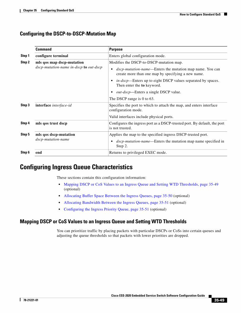
Chapter 35 Configuring Standard QoSHow to Configure Standard QoS
Configuring the DSCP-to-DSCP-Mutation Map
Configuring Ingress Queue CharacteristicsThese sections contain this configuration information:
• Mapping DSCP or CoS Values to an Ingress Queue and Setting WTD Thresholds, page 35-49 (optional)
• Allocating Buffer Space Between the Ingress Queues, page 35-50 (optional)
• Allocating Bandwidth Between the Ingress Queues, page 35-51 (optional)
• Configuring the Ingress Priority Queue, page 35-51 (optional)
Mapping DSCP or CoS Values to an Ingress Queue and Setting WTD Thresholds
You can prioritize traffic by placing packets with particular DSCPs or CoSs into certain queues and adjusting the queue thresholds so that packets with lower priorities are dropped.
Command Purpose
Step 1 configure terminal Enters global configuration mode.
Step 2 mls qos map dscp-mutation dscp-mutation-name in-dscp to out-dscp
Modifies the DSCP-to-DSCP-mutation map.
• dscp-mutation-name—Enters the mutation map name. You can create more than one map by specifying a new name.
• in-dscp—Enters up to eight DSCP values separated by spaces. Then enter the to keyword.
• out-dscp—Enters a single DSCP value.
The DSCP range is 0 to 63.
Step 3 interface interface-id Specifies the port to which to attach the map, and enters interface configuration mode.
Valid interfaces include physical ports.
Step 4 mls qos trust dscp Configures the ingress port as a DSCP-trusted port. By default, the port is not trusted.
Step 5 mls qos dscp-mutation dscp-mutation-name
Applies the map to the specified ingress DSCP-trusted port.
• dscp-mutation-name—Enters the mutation map name specified in Step 2.
Step 6 end Returns to privileged EXEC mode.
35-49Cisco ESS-2020 Embedded Service Switch Software Configuration Guide
78-21221-01
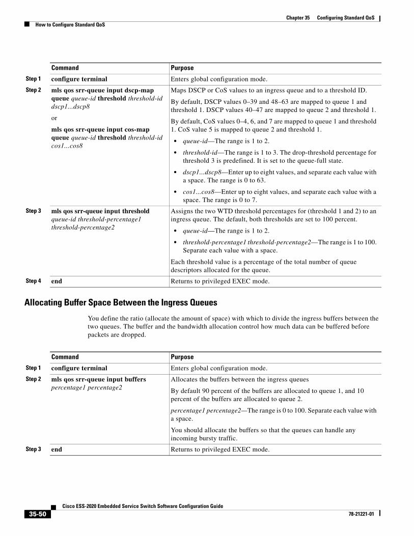
Chapter 35 Configuring Standard QoSHow to Configure Standard QoS
Allocating Buffer Space Between the Ingress Queues
You define the ratio (allocate the amount of space) with which to divide the ingress buffers between the two queues. The buffer and the bandwidth allocation control how much data can be buffered before packets are dropped.
Command Purpose
Step 1 configure terminal Enters global configuration mode.
Step 2 mls qos srr-queue input dscp-map queue queue-id threshold threshold-id dscp1...dscp8
or
mls qos srr-queue input cos-map queue queue-id threshold threshold-id cos1...cos8
Maps DSCP or CoS values to an ingress queue and to a threshold ID.
By default, DSCP values 0–39 and 48–63 are mapped to queue 1 and threshold 1. DSCP values 40–47 are mapped to queue 2 and threshold 1.
By default, CoS values 0–4, 6, and 7 are mapped to queue 1 and threshold 1. CoS value 5 is mapped to queue 2 and threshold 1.
• queue-id—The range is 1 to 2.
• threshold-id—The range is 1 to 3. The drop-threshold percentage for threshold 3 is predefined. It is set to the queue-full state.
• dscp1...dscp8—Enter up to eight values, and separate each value with a space. The range is 0 to 63.
• cos1...cos8—Enter up to eight values, and separate each value with a space. The range is 0 to 7.
Step 3 mls qos srr-queue input threshold queue-id threshold-percentage1 threshold-percentage2
Assigns the two WTD threshold percentages for (threshold 1 and 2) to an ingress queue. The default, both thresholds are set to 100 percent.
• queue-id—The range is 1 to 2.
• threshold-percentage1 threshold-percentage2—The range is 1 to 100. Separate each value with a space.
Each threshold value is a percentage of the total number of queue descriptors allocated for the queue.
Step 4 end Returns to privileged EXEC mode.
Command Purpose
Step 1 configure terminal Enters global configuration mode.
Step 2 mls qos srr-queue input buffers percentage1 percentage2
Allocates the buffers between the ingress queues
By default 90 percent of the buffers are allocated to queue 1, and 10 percent of the buffers are allocated to queue 2.
percentage1 percentage2—The range is 0 to 100. Separate each value with a space.
You should allocate the buffers so that the queues can handle any incoming bursty traffic.
Step 3 end Returns to privileged EXEC mode.
35-50Cisco ESS-2020 Embedded Service Switch Software Configuration Guide
78-21221-01
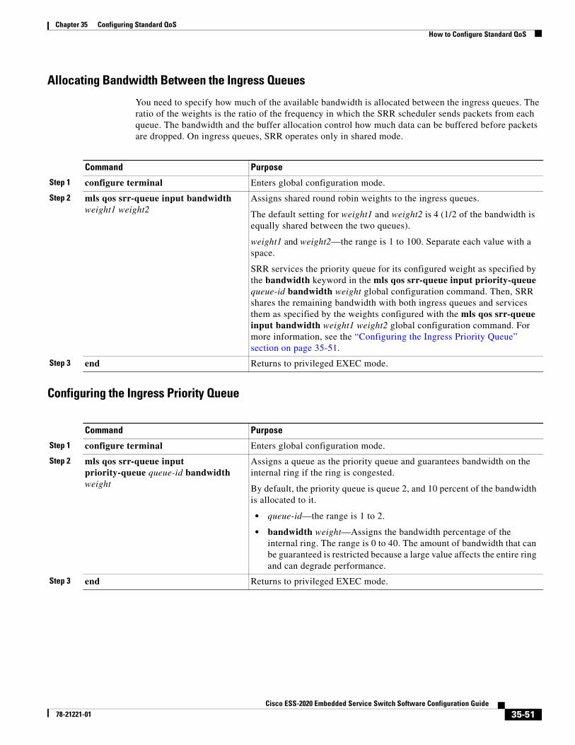
Chapter 35 Configuring Standard QoSHow to Configure Standard QoS
Allocating Bandwidth Between the Ingress Queues
You need to specify how much of the available bandwidth is allocated between the ingress queues. The ratio of the weights is the ratio of the frequency in which the SRR scheduler sends packets from each queue. The bandwidth and the buffer allocation control how much data can be buffered before packets are dropped. On ingress queues, SRR operates only in shared mode.
Configuring the Ingress Priority Queue
Command Purpose
Step 1 configure terminal Enters global configuration mode.
Step 2 mls qos srr-queue input bandwidth weight1 weight2
Assigns shared round robin weights to the ingress queues.
The default setting for weight1 and weight2 is 4 (1/2 of the bandwidth is equally shared between the two queues).
weight1 and weight2—the range is 1 to 100. Separate each value with a space.
SRR services the priority queue for its configured weight as specified by the bandwidth keyword in the mls qos srr-queue input priority-queue queue-id bandwidth weight global configuration command. Then, SRR shares the remaining bandwidth with both ingress queues and services them as specified by the weights configured with the mls qos srr-queue input bandwidth weight1 weight2 global configuration command. For more information, see the “Configuring the Ingress Priority Queue” section on page 35-51.
Step 3 end Returns to privileged EXEC mode.
Command Purpose
Step 1 configure terminal Enters global configuration mode.
Step 2 mls qos srr-queue input priority-queue queue-id bandwidth weight
Assigns a queue as the priority queue and guarantees bandwidth on the internal ring if the ring is congested.
By default, the priority queue is queue 2, and 10 percent of the bandwidth is allocated to it.
• queue-id—the range is 1 to 2.
• bandwidth weight—Assigns the bandwidth percentage of the internal ring. The range is 0 to 40. The amount of bandwidth that can be guaranteed is restricted because a large value affects the entire ring and can degrade performance.
Step 3 end Returns to privileged EXEC mode.
35-51Cisco ESS-2020 Embedded Service Switch Software Configuration Guide
78-21221-01
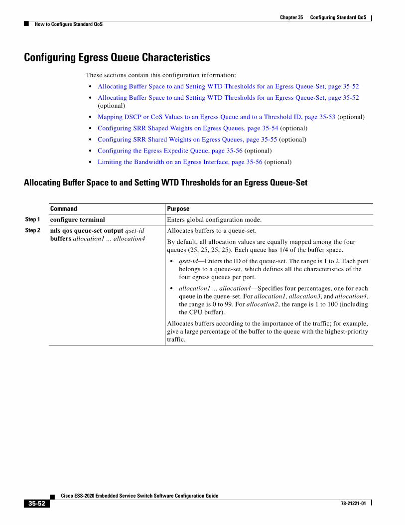
Chapter 35 Configuring Standard QoSHow to Configure Standard QoS
Configuring Egress Queue CharacteristicsThese sections contain this configuration information:
• Allocating Buffer Space to and Setting WTD Thresholds for an Egress Queue-Set, page 35-52
• Allocating Buffer Space to and Setting WTD Thresholds for an Egress Queue-Set, page 35-52 (optional)
• Mapping DSCP or CoS Values to an Egress Queue and to a Threshold ID, page 35-53 (optional)
• Configuring SRR Shaped Weights on Egress Queues, page 35-54 (optional)
• Configuring SRR Shared Weights on Egress Queues, page 35-55 (optional)
• Configuring the Egress Expedite Queue, page 35-56 (optional)
• Limiting the Bandwidth on an Egress Interface, page 35-56 (optional)
Allocating Buffer Space to and Setting WTD Thresholds for an Egress Queue-Set
Command Purpose
Step 1 configure terminal Enters global configuration mode.
Step 2 mls qos queue-set output qset-id buffers allocation1 ... allocation4
Allocates buffers to a queue-set.
By default, all allocation values are equally mapped among the four queues (25, 25, 25, 25). Each queue has 1/4 of the buffer space.
• qset-id—Enters the ID of the queue-set. The range is 1 to 2. Each port belongs to a queue-set, which defines all the characteristics of the four egress queues per port.
• allocation1 ... allocation4—Specifies four percentages, one for each queue in the queue-set. For allocation1, allocation3, and allocation4, the range is 0 to 99. For allocation2, the range is 1 to 100 (including the CPU buffer).
Allocates buffers according to the importance of the traffic; for example, give a large percentage of the buffer to the queue with the highest-priority traffic.
35-52Cisco ESS-2020 Embedded Service Switch Software Configuration Guide
78-21221-01
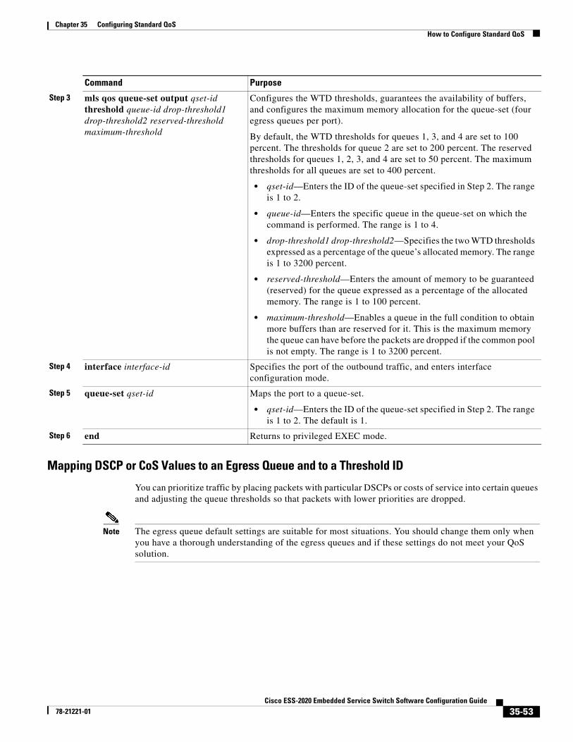
Chapter 35 Configuring Standard QoSHow to Configure Standard QoS
Mapping DSCP or CoS Values to an Egress Queue and to a Threshold ID
You can prioritize traffic by placing packets with particular DSCPs or costs of service into certain queues and adjusting the queue thresholds so that packets with lower priorities are dropped.
Note The egress queue default settings are suitable for most situations. You should change them only when you have a thorough understanding of the egress queues and if these settings do not meet your QoS solution.
Step 3 mls qos queue-set output qset-id threshold queue-id drop-threshold1 drop-threshold2 reserved-threshold maximum-threshold
Configures the WTD thresholds, guarantees the availability of buffers, and configures the maximum memory allocation for the queue-set (four egress queues per port).
By default, the WTD thresholds for queues 1, 3, and 4 are set to 100 percent. The thresholds for queue 2 are set to 200 percent. The reserved thresholds for queues 1, 2, 3, and 4 are set to 50 percent. The maximum thresholds for all queues are set to 400 percent.
• qset-id—Enters the ID of the queue-set specified in Step 2. The range is 1 to 2.
• queue-id—Enters the specific queue in the queue-set on which the command is performed. The range is 1 to 4.
• drop-threshold1 drop-threshold2—Specifies the two WTD thresholds expressed as a percentage of the queue’s allocated memory. The range is 1 to 3200 percent.
• reserved-threshold—Enters the amount of memory to be guaranteed (reserved) for the queue expressed as a percentage of the allocated memory. The range is 1 to 100 percent.
• maximum-threshold—Enables a queue in the full condition to obtain more buffers than are reserved for it. This is the maximum memory the queue can have before the packets are dropped if the common pool is not empty. The range is 1 to 3200 percent.
Step 4 interface interface-id Specifies the port of the outbound traffic, and enters interface configuration mode.
Step 5 queue-set qset-id Maps the port to a queue-set.
• qset-id—Enters the ID of the queue-set specified in Step 2. The range is 1 to 2. The default is 1.
Step 6 end Returns to privileged EXEC mode.
Command Purpose
35-53Cisco ESS-2020 Embedded Service Switch Software Configuration Guide
78-21221-01
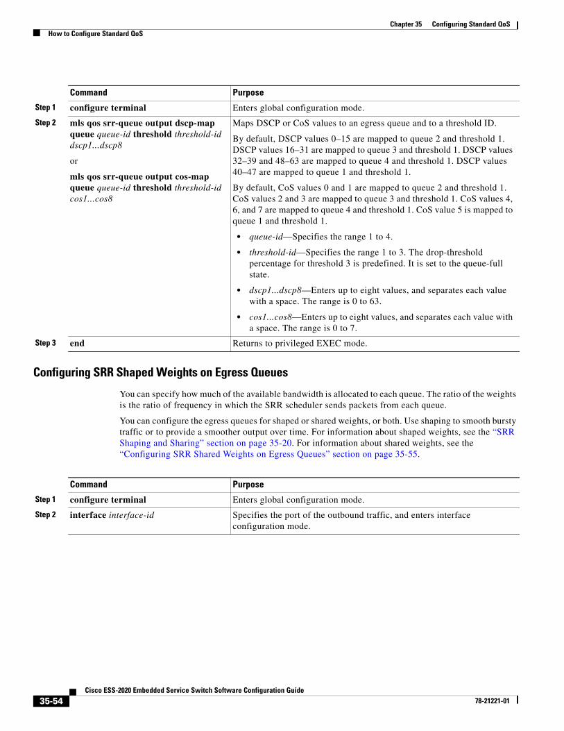
Chapter 35 Configuring Standard QoSHow to Configure Standard QoS
Configuring SRR Shaped Weights on Egress Queues
You can specify how much of the available bandwidth is allocated to each queue. The ratio of the weights is the ratio of frequency in which the SRR scheduler sends packets from each queue.
You can configure the egress queues for shaped or shared weights, or both. Use shaping to smooth bursty traffic or to provide a smoother output over time. For information about shaped weights, see the “SRR Shaping and Sharing” section on page 35-20. For information about shared weights, see the “Configuring SRR Shared Weights on Egress Queues” section on page 35-55.
Command Purpose
Step 1 configure terminal Enters global configuration mode.
Step 2 mls qos srr-queue output dscp-map queue queue-id threshold threshold-id dscp1...dscp8
or
mls qos srr-queue output cos-map queue queue-id threshold threshold-id cos1...cos8
Maps DSCP or CoS values to an egress queue and to a threshold ID.
By default, DSCP values 0–15 are mapped to queue 2 and threshold 1. DSCP values 16–31 are mapped to queue 3 and threshold 1. DSCP values 32–39 and 48–63 are mapped to queue 4 and threshold 1. DSCP values 40–47 are mapped to queue 1 and threshold 1.
By default, CoS values 0 and 1 are mapped to queue 2 and threshold 1. CoS values 2 and 3 are mapped to queue 3 and threshold 1. CoS values 4, 6, and 7 are mapped to queue 4 and threshold 1. CoS value 5 is mapped to queue 1 and threshold 1.
• queue-id—Specifies the range 1 to 4.
• threshold-id—Specifies the range 1 to 3. The drop-threshold percentage for threshold 3 is predefined. It is set to the queue-full state.
• dscp1...dscp8—Enters up to eight values, and separates each value with a space. The range is 0 to 63.
• cos1...cos8—Enters up to eight values, and separates each value with a space. The range is 0 to 7.
Step 3 end Returns to privileged EXEC mode.
Command Purpose
Step 1 configure terminal Enters global configuration mode.
Step 2 interface interface-id Specifies the port of the outbound traffic, and enters interface configuration mode.
35-54Cisco ESS-2020 Embedded Service Switch Software Configuration Guide
78-21221-01
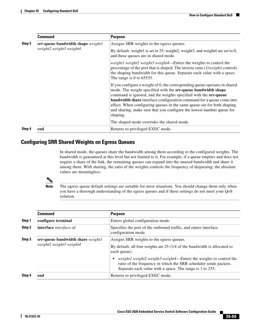
Chapter 35 Configuring Standard QoSHow to Configure Standard QoS
Configuring SRR Shared Weights on Egress Queues
In shared mode, the queues share the bandwidth among them according to the configured weights. The bandwidth is guaranteed at this level but not limited to it. For example, if a queue empties and does not require a share of the link, the remaining queues can expand into the unused bandwidth and share it among them. With sharing, the ratio of the weights controls the frequency of dequeuing; the absolute values are meaningless.
Note The egress queue default settings are suitable for most situations. You should change them only when you have a thorough understanding of the egress queues and if these settings do not meet your QoS solution.
Step 3 srr-queue bandwidth shape weight1 weight2 weight3 weight4
Assigns SRR weights to the egress queues.
By default, weight1 is set to 25; weight2, weight3, and weight4 are set to 0, and these queues are in shared mode.
weight1 weight2 weight3 weight4—Enters the weights to control the percentage of the port that is shaped. The inverse ratio (1/weight) controls the shaping bandwidth for this queue. Separate each value with a space. The range is 0 to 65535.
If you configure a weight of 0, the corresponding queue operates in shared mode. The weight specified with the srr-queue bandwidth shape command is ignored, and the weights specified with the srr-queue bandwidth share interface configuration command for a queue come into effect. When configuring queues in the same queue-set for both shaping and sharing, make sure that you configure the lowest number queue for shaping.
The shaped mode overrides the shared mode.
Step 4 end Returns to privileged EXEC mode.
Command Purpose
Command Purpose
Step 1 configure terminal Enters global configuration mode.
Step 2 interface interface-id Specifies the port of the outbound traffic, and enters interface configuration mode.
Step 3 srr-queue bandwidth share weight1 weight2 weight3 weight4
Assigns SRR weights to the egress queues.
By default, all four weights are 25 (1/4 of the bandwidth is allocated to each queue).
• weight1 weight2 weight3 weight4—Enters the weights to control the ratio of the frequency in which the SRR scheduler sends packets. Separate each value with a space. The range is 1 to 255.
Step 4 end Returns to privileged EXEC mode.
35-55Cisco ESS-2020 Embedded Service Switch Software Configuration Guide
78-21221-01
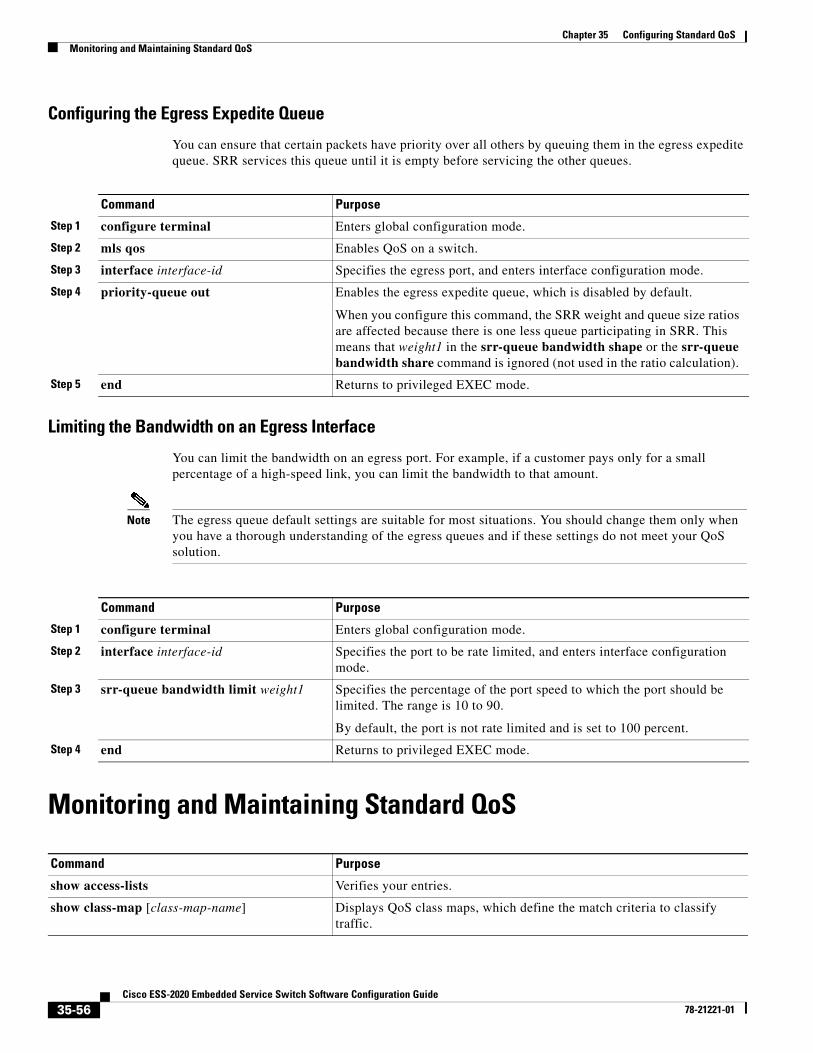
Chapter 35 Configuring Standard QoSMonitoring and Maintaining Standard QoS
Configuring the Egress Expedite Queue
You can ensure that certain packets have priority over all others by queuing them in the egress expedite queue. SRR services this queue until it is empty before servicing the other queues.
Limiting the Bandwidth on an Egress Interface
You can limit the bandwidth on an egress port. For example, if a customer pays only for a small percentage of a high-speed link, you can limit the bandwidth to that amount.
Note The egress queue default settings are suitable for most situations. You should change them only when you have a thorough understanding of the egress queues and if these settings do not meet your QoS solution.
Monitoring and Maintaining Standard QoS
Command Purpose
Step 1 configure terminal Enters global configuration mode.
Step 2 mls qos Enables QoS on a switch.
Step 3 interface interface-id Specifies the egress port, and enters interface configuration mode.
Step 4 priority-queue out Enables the egress expedite queue, which is disabled by default.
When you configure this command, the SRR weight and queue size ratios are affected because there is one less queue participating in SRR. This means that weight1 in the srr-queue bandwidth shape or the srr-queue bandwidth share command is ignored (not used in the ratio calculation).
Step 5 end Returns to privileged EXEC mode.
Command Purpose
Step 1 configure terminal Enters global configuration mode.
Step 2 interface interface-id Specifies the port to be rate limited, and enters interface configuration mode.
Step 3 srr-queue bandwidth limit weight1 Specifies the percentage of the port speed to which the port should be limited. The range is 10 to 90.
By default, the port is not rate limited and is set to 100 percent.
Step 4 end Returns to privileged EXEC mode.
Command Purpose
show access-lists Verifies your entries.
show class-map [class-map-name] Displays QoS class maps, which define the match criteria to classify traffic.
35-56Cisco ESS-2020 Embedded Service Switch Software Configuration Guide
78-21221-01
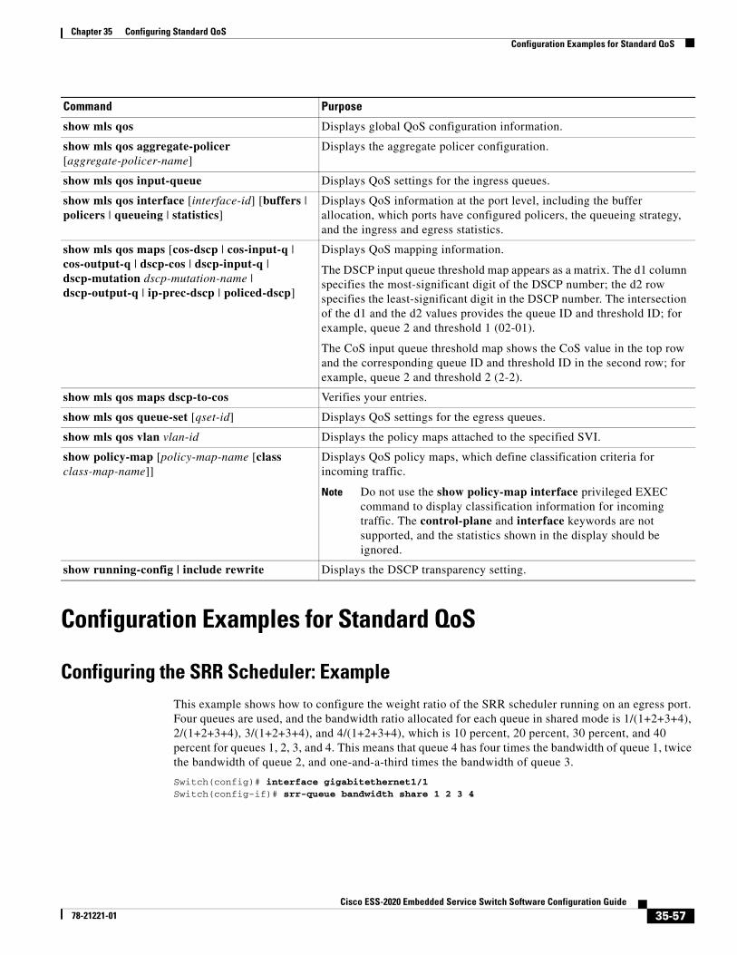
Chapter 35 Configuring Standard QoSConfiguration Examples for Standard QoS
Configuration Examples for Standard QoS
Configuring the SRR Scheduler: ExampleThis example shows how to configure the weight ratio of the SRR scheduler running on an egress port. Four queues are used, and the bandwidth ratio allocated for each queue in shared mode is 1/(1+2+3+4), 2/(1+2+3+4), 3/(1+2+3+4), and 4/(1+2+3+4), which is 10 percent, 20 percent, 30 percent, and 40 percent for queues 1, 2, 3, and 4. This means that queue 4 has four times the bandwidth of queue 1, twice the bandwidth of queue 2, and one-and-a-third times the bandwidth of queue 3.
Switch(config)# interface gigabitethernet1/1Switch(config-if)# srr-queue bandwidth share 1 2 3 4
show mls qos Displays global QoS configuration information.
show mls qos aggregate-policer [aggregate-policer-name]
Displays the aggregate policer configuration.
show mls qos input-queue Displays QoS settings for the ingress queues.
show mls qos interface [interface-id] [buffers | policers | queueing | statistics]
Displays QoS information at the port level, including the buffer allocation, which ports have configured policers, the queueing strategy, and the ingress and egress statistics.
show mls qos maps [cos-dscp | cos-input-q | cos-output-q | dscp-cos | dscp-input-q | dscp-mutation dscp-mutation-name | dscp-output-q | ip-prec-dscp | policed-dscp]
Displays QoS mapping information.
The DSCP input queue threshold map appears as a matrix. The d1 column specifies the most-significant digit of the DSCP number; the d2 row specifies the least-significant digit in the DSCP number. The intersection of the d1 and the d2 values provides the queue ID and threshold ID; for example, queue 2 and threshold 1 (02-01).
The CoS input queue threshold map shows the CoS value in the top row and the corresponding queue ID and threshold ID in the second row; for example, queue 2 and threshold 2 (2-2).
show mls qos maps dscp-to-cos Verifies your entries.
show mls qos queue-set [qset-id] Displays QoS settings for the egress queues.
show mls qos vlan vlan-id Displays the policy maps attached to the specified SVI.
show policy-map [policy-map-name [class class-map-name]]
Displays QoS policy maps, which define classification criteria for incoming traffic.
Note Do not use the show policy-map interface privileged EXEC command to display classification information for incoming traffic. The control-plane and interface keywords are not supported, and the statistics shown in the display should be ignored.
show running-config | include rewrite Displays the DSCP transparency setting.
Command Purpose
35-57Cisco ESS-2020 Embedded Service Switch Software Configuration Guide
78-21221-01
Chapter 35 Configuring Standard QoSConfiguration Examples for Standard QoS
Configuring DSCP-Trusted State on a Port: ExampleThis example shows how to configure a port to the DSCP-trusted state and to modify the DSCP-to-DSCP-mutation map (named gi0/2-mutation) so that incoming DSCP values 10 to 13 are mapped to DSCP 30:
Switch(config)# mls qos map dscp-mutation gi1/2-mutation 10 11 12 13 to 30Switch(config)# interface gigabitethernet1/2Switch(config-if)# mls qos trust dscpSwitch(config-if)# mls qos dscp-mutation gi1/2-mutationSwitch(config-if)# end
Allowing ACL Permission for IP Traffic: ExamplesThis example shows how to allow access for only those hosts on the three specified networks. The wildcard bits apply to the host portions of the network addresses. Any host with a source address that does not match the access list statements is rejected.
Switch(config)# access-list 1 permit 192.5.255.0 0.0.0.255Switch(config)# access-list 1 permit 128.88.0.0 0.0.255.255Switch(config)# access-list 1 permit 36.0.0.0 0.0.0.255! (Note: all other access implicitly denied)
This example shows how to create an ACL that permits IP traffic from any source to any destination that has the DSCP value set to 32:
Switch(config)# access-list 100 permit ip any any dscp 32
This example shows how to create an ACL that permits IP traffic from a source host at 10.1.1.1 to a destination host at 10.1.1.2 with a precedence value of 5:
Switch(config)# access-list 100 permit ip host 10.1.1.1 host 10.1.1.2 precedence 5
This example shows how to create an ACL that permits PIM traffic from any source to a destination group address of 224.0.0.2 with a DSCP set to 32:
Switch(config)# access-list 102 permit pim any 224.0.0.2 dscp 32
Configuring a Class Map: ExamplesThis example shows how to configure the class map called class1. The class1 has one match criterion, which is access list 103. It permits traffic from any host to any destination that matches a DSCP value of 10.
Switch(config)# access-list 103 permit ip any any dscp 10Switch(config)# class-map class1Switch(config-cmap)# match access-group 103Switch(config-cmap)# endSwitch#
This example shows how to create a class map called class2, which matches incoming traffic with DSCP values of 10, 11, and 12.
Switch(config)# class-map class2Switch(config-cmap)# match ip dscp 10 11 12Switch(config-cmap)# endSwitch#
35-58Cisco ESS-2020 Embedded Service Switch Software Configuration Guide
78-21221-01
Chapter 35 Configuring Standard QoSConfiguration Examples for Standard QoS
This example shows how to create a class map called class3, which matches incoming traffic with IP-precedence values of 5, 6, and 7:
Switch(config)# class-map class3Switch(config-cmap)# match ip precedence 5 6 7 Switch(config-cmap)# endSwitch#
Creating a Policy Map: ExampleThis example shows how to create a policy map and attach it to an ingress port. In the configuration, the IP standard ACL permits traffic from network 10.1.0.0. For traffic matching this classification, the DSCP value in the incoming packet is trusted. If the matched traffic exceeds an average traffic rate of 48000 b/s and a normal burst size of 8000 bytes, its DSCP is marked down (based on the policed-DSCP map) and sent:
Switch(config)# access-list 1 permit 10.1.0.0 0.0.255.255Switch(config)# class-map ipclass1Switch(config-cmap)# match access-group 1Switch(config-cmap)# exitSwitch(config)# policy-map flow1tSwitch(config-pmap)# class ipclass1Switch(config-pmap-c)# trust dscpSwitch(config-pmap-c)# police 1000000 8000 exceed-action policed-dscp-transmitSwitch(config-pmap-c)# exitSwitch(config-pmap)# exitSwitch(config)# interface gigabitethernet1/1Switch(config-if)# service-policy input flow1t
Creating a Layer 2 MAC ACL: ExampleThis example shows how to create a Layer 2 MAC ACL with two permit statements and attach it to an ingress port. The first permit statement allows traffic from the host with MAC address 0001.0000.0001 destined for the host with MAC address 0002.0000.0001. The second permit statement allows only Ethertype XNS-IDP traffic from the host with MAC address 0001.0000.0002 destined for the host with MAC address 0002.0000.0002.
Switch(config)# mac access-list extended maclist1Switch(config-ext-mac)# permit 0001.0000.0001 0.0.0 0002.0000.0001 0.0.0Switch(config-ext-mac)# permit 0001.0000.0002 0.0.0 0002.0000.0002 0.0.0 xns-idpSwitch(config-ext-mac)# exitSwitch(config)# mac access-list extended maclist2Switch(config-ext-mac)# permit 0001.0000.0003 0.0.0 0002.0000.0003 0.0.0Switch(config-ext-mac)# permit 0001.0000.0004 0.0.0 0002.0000.0004 0.0.0 aarpSwitch(config-ext-mac)# exitSwitch(config)# class-map macclass1Switch(config-cmap)# match access-group maclist1Switch(config-cmap)# exitSwitch(config)# policy-map macpolicy1Switch(config-pmap)# class macclass1Switch(config-pmap-c)# set dscp 63Switch(config-pmap-c)# exitSwitch(config-pmap)# class macclass2 maclist2Switch(config-pmap-c)# set dscp 45Switch(config-pmap-c)# exitSwitch(config-pmap)# exitSwitch(config)# interface gigabitethernet1/1Switch(config-if)# mls qos trust cosSwitch(config-if)# service-policy input macpolicy1
35-59Cisco ESS-2020 Embedded Service Switch Software Configuration Guide
78-21221-01
Chapter 35 Configuring Standard QoSConfiguration Examples for Standard QoS
Creating an Aggregate Policer: ExampleThis example shows how to create an aggregate policer and attach it to multiple classes within a policy map. In the configuration, the IP ACLs permit traffic from network 10.1.0.0 and from host 11.3.1.1. For traffic coming from network 10.1.0.0, the DSCP in the incoming packets is trusted. For traffic coming from host 11.3.1.1, the DSCP in the packet is changed to 56. The traffic rate from the 10.1.0.0 network and from host 11.3.1.1 is policed. If the traffic exceeds an average rate of 48000 b/s and a normal burst size of 8000 bytes, its DSCP is marked down (based on the policed-DSCP map) and sent. The policy map is attached to an ingress port.
Switch(config)# access-list 1 permit 10.1.0.0 0.0.255.255Switch(config)# access-list 2 permit 11.3.1.1Switch(config)# mls qos aggregate-police transmit1 48000 8000 exceed-action policed-dscp-transmitSwitch(config)# class-map ipclass1Switch(config-cmap)# match access-group 1Switch(config-cmap)# exitSwitch(config)# class-map ipclass2Switch(config-cmap)# match access-group 2Switch(config-cmap)# exitSwitch(config)# policy-map aggflow1Switch(config-pmap)# class ipclass1Switch(config-pmap-c)# trust dscpSwitch(config-pmap-c)# police aggregate transmit1Switch(config-pmap-c)# exitSwitch(config-pmap)# class ipclass2Switch(config-pmap-c)# set dscp 56Switch(config-pmap-c)# police aggregate transmit1Switch(config-pmap-c)# exitSwitch(config-pmap)# exitSwitch(config)# interface gigabitethernet1/1Switch(config-if)# service-policy input aggflow1Switch(config-if)# exit
Configuring COS-to-DSCP Map: ExampleThis example shows how to modify and display the CoS-to-DSCP map:
Switch(config)# mls qos map cos-dscp 10 15 20 25 30 35 40 45Switch(config)# endSwitch# show mls qos maps cos-dscp
Cos-dscp map: cos: 0 1 2 3 4 5 6 7 -------------------------------- dscp: 10 15 20 25 30 35 40 45
35-60Cisco ESS-2020 Embedded Service Switch Software Configuration Guide
78-21221-01
Chapter 35 Configuring Standard QoSConfiguration Examples for Standard QoS
Configuring DSCP Maps: ExamplesThis example shows how to modify and display the IP-precedence-to-DSCP map:
Switch(config)# mls qos map ip-prec-dscp 10 15 20 25 30 35 40 45Switch(config)# endSwitch# show mls qos maps ip-prec-dscp
IpPrecedence-dscp map: ipprec: 0 1 2 3 4 5 6 7 -------------------------------- dscp: 10 15 20 25 30 35 40 45
This example shows how to map DSCP 50 to 57 to a marked-down DSCP value of 0:
Switch(config)# mls qos map policed-dscp 50 51 52 53 54 55 56 57 to 0Switch(config)# endSwitch# show mls qos maps policed-dscpPoliced-dscp map: d1 : d2 0 1 2 3 4 5 6 7 8 9 --------------------------------------- 0 : 00 01 02 03 04 05 06 07 08 09 1 : 10 11 12 13 14 15 16 17 18 19 2 : 20 21 22 23 24 25 26 27 28 29 3 : 30 31 32 33 34 35 36 37 38 39 4 : 40 41 42 43 44 45 46 47 48 49 5 : 00 00 00 00 00 00 00 00 58 59 6 : 60 61 62 63
Note In this policed-DSCP map, the marked-down DSCP values are shown in the body of the matrix. The d1 column specifies the most-significant digit of the original DSCP; the d2 row specifies the least-significant digit of the original DSCP. The intersection of the d1 and d2 values provides the marked-down value. For example, an original DSCP value of 53 corresponds to a marked-down DSCP value of 0.
This example shows how to map DSCP values 0, 8, 16, 24, 32, 40, 48, and 50 to CoS value 0 and to display the map:
Switch(config)# mls qos map dscp-cos 0 8 16 24 32 40 48 50 to 0Switch(config)# endSwitch# show mls qos maps dscp-cosDscp-cos map: d1 : d2 0 1 2 3 4 5 6 7 8 9 --------------------------------------- 0 : 00 00 00 00 00 00 00 00 00 01 1 : 01 01 01 01 01 01 00 02 02 02 2 : 02 02 02 02 00 03 03 03 03 03 3 : 03 03 00 04 04 04 04 04 04 04 4 : 00 05 05 05 05 05 05 05 00 06 5 : 00 06 06 06 06 06 07 07 07 07 6 : 07 07 07 07
Note In the above DSCP-to-CoS map, the CoS values are shown in the body of the matrix. The d1 column specifies the most-significant digit of the DSCP; the d2 row specifies the least-significant digit of the DSCP. The intersection of the d1 and d2 values provides the CoS value. For example, in the DSCP-to-CoS map, a DSCP value of 08 corresponds to a CoS value of 0.
35-61Cisco ESS-2020 Embedded Service Switch Software Configuration Guide
78-21221-01
Chapter 35 Configuring Standard QoSConfiguration Examples for Standard QoS
This example shows how to define the DSCP-to-DSCP mutation map. All the entries that are not explicitly configured are not modified (remains as specified in the null map):
Switch(config)# mls qos map dscp-mutation mutation1 1 2 3 4 5 6 7 to 0Switch(config)# mls qos map dscp-mutation mutation1 8 9 10 11 12 13 to 10Switch(config)# mls qos map dscp-mutation mutation1 20 21 22 to 20Switch(config)# mls qos map dscp-mutation mutation1 30 31 32 33 34 to 30Switch(config)# interface gigabitethernet1/1Switch(config-if)# mls qos trust dscpSwitch(config-if)# mls qos dscp-mutation mutation1Switch(config-if)# endSwitch# show mls qos maps dscp-mutation mutation1Dscp-dscp mutation map: mutation1: d1 : d2 0 1 2 3 4 5 6 7 8 9 --------------------------------------- 0 : 00 00 00 00 00 00 00 00 10 10 1 : 10 10 10 10 14 15 16 17 18 19 2 : 20 20 20 23 24 25 26 27 28 29 3 : 30 30 30 30 30 35 36 37 38 39 4 : 40 41 42 43 44 45 46 47 48 49 5 : 50 51 52 53 54 55 56 57 58 59 6 : 60 61 62 63
Note In the above DSCP-to-DSCP-mutation map, the mutated values are shown in the body of the matrix. The d1 column specifies the most-significant digit of the original DSCP; the d2 row specifies the least-significant digit of the original DSCP. The intersection of the d1 and d2 values provides the mutated value. For example, a DSCP value of 12 corresponds to a mutated value of 10.
This example shows how to map DSCP values 0 to 6 to ingress queue 1 and to threshold 1 with a drop threshold of 50 percent. It maps DSCP values 20 to 26 to ingress queue 1 and to threshold 2 with a drop threshold of 70 percent:
Switch(config)# mls qos srr-queue input dscp-map queue 1 threshold 1 0 1 2 3 4 5 6Switch(config)# mls qos srr-queue input dscp-map queue 1 threshold 2 20 21 22 23 24 25 26Switch(config)# mls qos srr-queue input threshold 1 50 70
In this example, the DSCP values (0 to 6) are assigned the WTD threshold of 50 percent and will be dropped sooner than the DSCP values (20 to 26) assigned to the WTD threshold of 70 percent.
Configuring an Ingress Queue: ExampleThis example shows how to allocate 60 percent of the buffer space to ingress queue 1 and 40 percent of the buffer space to ingress queue 2:
Switch(config)# mls qos srr-queue input buffers 60 40
This example shows how to assign the ingress bandwidth to the queues. Priority queueing is disabled, and the shared bandwidth ratio allocated to queue 1 is 25/(25+75) and to queue 2 is 75/(25+75):
Switch(config)# mls qos srr-queue input priority-queue 2 bandwidth 0Switch(config)# mls qos srr-queue input bandwidth 25 75
To return to the default setting, use the no mls qos srr-queue input priority-queue queue-id global configuration command. To disable priority queueing, set the bandwidth weight to 0, for example, mls qos srr-queue input priority-queue queue-id bandwidth 0.
35-62Cisco ESS-2020 Embedded Service Switch Software Configuration Guide
78-21221-01
Chapter 35 Configuring Standard QoSConfiguration Examples for Standard QoS
This example shows how to assign the ingress bandwidths to the queues. Queue 1 is the priority queue with 10 percent of the bandwidth allocated to it. The bandwidth ratios allocated to queues 1 and 2 is 4/(4+4). SRR services queue 1 (the priority queue) first for its configured 10 percent bandwidth. Then SRR equally shares the remaining 90 percent of the bandwidth between queues 1 and 2 by allocating 45 percent to each queue:
Switch(config)# mls qos srr-queue input priority-queue 1 bandwidth 10Switch(config)# mls qos srr-queue input bandwidth 4 4
Configuring the Egress Queue: ExamplesThis example shows how to map a port to queue-set 2. It allocates 40 percent of the buffer space to egress queue 1 and 20 percent to egress queues 2, 3, and 4. It configures the drop thresholds for queue 2 to 40 and 60 percent of the allocated memory, guarantees (reserves) 100 percent of the allocated memory, and configures 200 percent as the maximum memory that this queue can have before packets are dropped:
Switch(config)# mls qos queue-set output 2 buffers 40 20 20 20Switch(config)# mls qos queue-set output 2 threshold 2 40 60 100 200Switch(config)# interface gigabitethernet1/1lSwitch(config-if)# queue-set 2
This example shows how to map DSCP values 10 and 11 to egress queue 1 and to threshold 2:
Switch(config)# mls qos srr-queue output dscp-map queue 1 threshold 2 10 11
This example shows how to configure bandwidth shaping on queue 1. Because the weight ratios for queues 2, 3, and 4 are set to 0, these queues operate in shared mode. The bandwidth weight for queue 1 is 1/8, which is 12.5 percent:
Switch(config)# interface gigabitethernet1/1Switch(config-if)# srr-queue bandwidth shape 8 0 0 0
This example shows how to enable the egress expedite queue when the SRR weights are configured. The egress expedite queue overrides the configured SRR weights.
Switch(config)# interface gigabitethernet1/1Switch(config-if)# srr-queue bandwidth shape 25 0 0 0Switch(config-if)# srr-queue bandwidth share 30 20 25 25Switch(config-if)# priority-queue outSwitch(config-if)# end
This example shows how to limit the bandwidth on a port to 80 percent:
Switch(config)# interface gigabitethernet1/1Switch(config-if)# srr-queue bandwidth limit 80
When you configure this command to 80 percent, the port is idle 20 percent of the time. The line rate drops to 80 percent of the connected speed, which is 800 Mb/s. These values are not exact because the hardware adjusts the line rate in increments of six.
Creating a Layer 2 MAC ACL: ExampleThis example shows how to create a Layer 2 MAC ACL with two permit statements. The first statement allows traffic from the host with MAC address 0001.0000.0001 to the host with MAC address 0002.0000.0001. The second statement allows only Ethertype XNS-IDP traffic from the host with MAC address 0001.0000.0002 to the host with MAC address 0002.0000.0002.
Switch(config)# mac access-list extended maclist1
35-63Cisco ESS-2020 Embedded Service Switch Software Configuration Guide
78-21221-01
Chapter 35 Configuring Standard QoSAdditional References
Switch(config-ext-macl)# permit 0001.0000.0001 0.0.0 0002.0000.0001 0.0.0Switch(config-ext-macl)# permit 0001.0000.0002 0.0.0 0002.0000.0002 0.0.0 xns-idp! (Note: all other access implicitly denied)
Additional ReferencesThe following sections provide references related to switch administration:
Related Documents
Standards
MIBs
RFCs
Related Topic Document Title
Cisco IE 2000 commands Cisco IE 2000 Switch Command Reference, Release 15.0(2)EC
Cisco IOS basic commands Cisco IOS Configuration Fundamentals Command Reference
Auto-QoS configuration Chapter 36, “Configuring Auto-QoS”
Standards Title
No new or modified standards are supported by this feature, and support for existing standards has not been modified by this feature.
—
MIBs MIBs Link
— To locate and download MIBs using Cisco IOS XR software, use the Cisco MIB Locator found at the following URL and choose a platform under the Cisco Access Products menu: http://cisco.com/public/sw-center/netmgmt/cmtk/mibs.shtml
RFCs Title
No new or modified RFCs are supported by this feature, and support for existing RFCs has not been modified by this feature.
—
35-64Cisco ESS-2020 Embedded Service Switch Software Configuration Guide
78-21221-01
Chapter 35 Configuring Standard QoSAdditional References
Technical Assistance
Description Link
The Cisco Technical Support website contains thousands of pages of searchable technical content, including links to products, technologies, solutions, technical tips, and tools. Registered Cisco.com users can log in from this page to access even more content.
http://www.cisco.com/techsupport
35-65Cisco ESS-2020 Embedded Service Switch Software Configuration Guide
78-21221-01
Chapter 35 Configuring Standard QoSAdditional References
35-66Cisco ESS-2020 Embedded Service Switch Software Configuration Guide
78-21221-01