Configuring IP Routing Protocol-Independent Features · Defines any route maps needed to control...
34
363 Cisco IOS IP and IP Routing Configuration Guide Configuring IP Routing Protocol-Independent Features This chapter describes how to configure IP routing protocol-independent features. For a complete description of the IP routing protocol-independent commands in this chapter, refer to the “IP Routing Protocol-Independent Commands” chapter of the Cisco IOS IP Command Reference, Volume 2 of 3: Routing Protocols publication. To locate documentation of other commands in this chapter, use the command reference master index, or search online. To identify the hardware platform or software image information associated with a feature, use the Feature Navigator on Cisco.com to search for information about the feature or refer to the software release notes for a specific release. For more information, see the “Identifying Supported Platforms” section in the “Using Cisco IOS Software” chapter in this book. Protocol-Independent Feature Task List Previous chapters addressed configurations of specific routing protocols. To configure optional protocol-independent features, perform any of the tasks described in the following sections: • Using Variable-Length Subnet Masks (Optional) • Configuring Static Routes (Optional) • Specifying Default Routes (Optional) • Changing the Maximum Number of Paths (Optional) • Configuring Multi-Interface Load Splitting (Optional) • Redistributing Routing Information (Optional) • Filtering Routing Information (Optional) • Enabling Policy Routing (PBR) (Optional) • Managing Authentication Keys (Optional) • Monitoring and Maintaining the IP Network (Optional) See the section “IP Routing Protocol-Independent Configuration Examples” at the end of this chapter for configuration examples.
Transcript of Configuring IP Routing Protocol-Independent Features · Defines any route maps needed to control...
363Cisco IOS IP and IP Routing Configuration Guide
Configuring IP Routing Protocol-IndependentFeatures
This chapter describes how to configure IP routing protocol-independent features. For a completedescription of the IP routing protocol-independent commands in this chapter, refer to the “IP RoutingProtocol-Independent Commands” chapter of theCisco IOS IP Command Reference, Volume 2 of 3:Routing Protocols publication. To locate documentation of other commands in this chapter, use thecommand reference master index, or search online.
To identify the hardware platform or software image information associated with a feature, use theFeature Navigator on Cisco.com to search for information about the feature or refer to the softwarerelease notes for a specific release. For more information, see the “Identifying Supported Platforms”section in the “Using Cisco IOS Software” chapter in this book.
Protocol-Independent Feature Task ListPrevious chapters addressed configurations of specific routing protocols. To configure optionalprotocol-independent features, perform any of the tasks described in the following sections:
• Using Variable-Length Subnet Masks (Optional)
• Configuring Static Routes (Optional)
• Specifying Default Routes (Optional)
• Changing the Maximum Number of Paths (Optional)
• Configuring Multi-Interface Load Splitting (Optional)
• Redistributing Routing Information (Optional)
• Filtering Routing Information (Optional)
• Enabling Policy Routing (PBR) (Optional)
• Managing Authentication Keys (Optional)
• Monitoring and Maintaining the IP Network (Optional)
See the section “IP Routing Protocol-Independent Configuration Examples” at the end of this chapterfor configuration examples.
Configuring IP Routing Protocol-Independent FeaturesUsing Variable-Length Subnet Masks
364Cisco IOS IP and IP Routing Configuration Guide
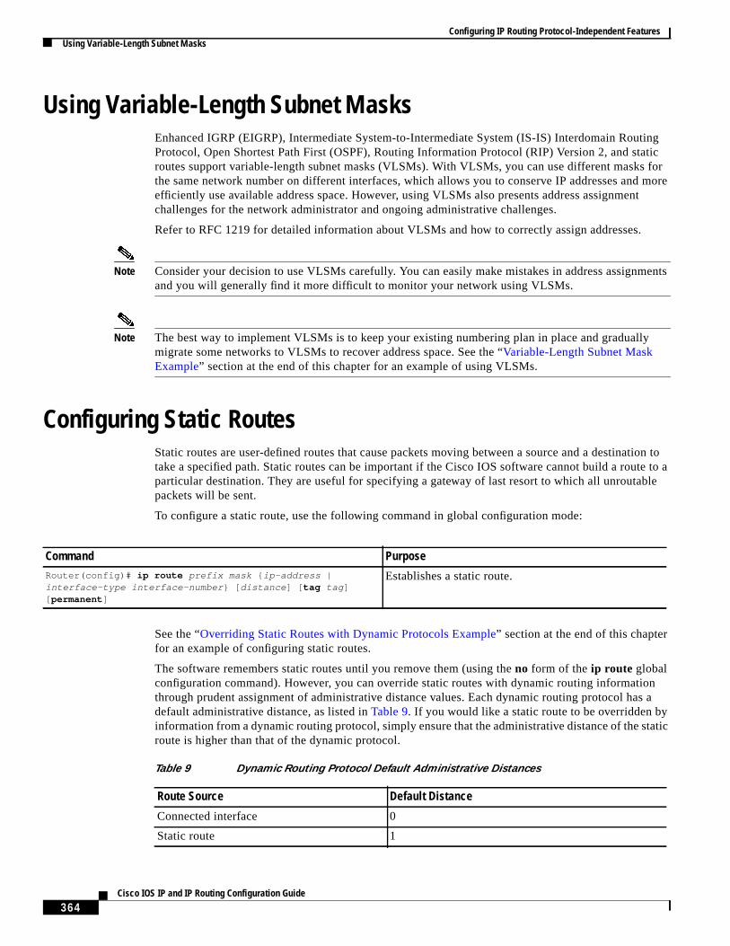
Using Variable-Length Subnet MasksEnhanced IGRP (EIGRP), Intermediate System-to-Intermediate System (IS-IS) Interdomain RoutingProtocol, Open Shortest Path First (OSPF), Routing Information Protocol (RIP) Version 2, and staticroutes support variable-length subnet masks (VLSMs). With VLSMs, you can use different masks forthe same network number on different interfaces, which allows you to conserve IP addresses and moreefficiently use available address space. However, using VLSMs also presents address assignmentchallenges for the network administrator and ongoing administrative challenges.
Refer to RFC 1219 for detailed information about VLSMs and how to correctly assign addresses.
Note Consider your decision to use VLSMs carefully. You can easily make mistakes in address assignmentsand you will generally find it more difficult to monitor your network using VLSMs.
Note The best way to implement VLSMs is to keep your existing numbering plan in place and graduallymigrate some networks to VLSMs to recover address space. See the “Variable-Length Subnet MaskExample” section at the end of this chapter for an example of using VLSMs.
Configuring Static RoutesStatic routes are user-defined routes that cause packets moving between a source and a destination totake a specified path. Static routes can be important if the Cisco IOS software cannot build a route to aparticular destination. They are useful for specifying a gateway of last resort to which all unroutablepackets will be sent.
To configure a static route, use the following command in global configuration mode:
See the “Overriding Static Routes with Dynamic Protocols Example” section at the end of this chapterfor an example of configuring static routes.
The software remembers static routes until you remove them (using theno form of theip route globalconfiguration command). However, you can override static routes with dynamic routing informationthrough prudent assignment of administrative distance values. Each dynamic routing protocol has adefault administrative distance, as listed inTable 9. If you would like a static route to be overridden byinformation from a dynamic routing protocol, simply ensure that the administrative distance of the staticroute is higher than that of the dynamic protocol.
Command PurposeRouter(config)# ip route prefix mask { ip-address |interface-type interface-number } [ distance ] [ tag tag ][ permanent ]
Establishes a static route.
Table 9 Dynamic Routing Protocol Default Administrative Distances
Route Source Default Distance
Connected interface 0
Static route 1

Configuring IP Routing Protocol-Independent FeaturesSpecifying Default Routes
365Cisco IOS IP and IP Routing Configuration Guide
Static routes that point to an interface will be advertised via RIP, IGRP, and other dynamic routingprotocols, regardless of whetherredistribute static router configuration commands were specified forthose routing protocols. These static routes are advertised because static routes that point to an interfaceare considered in the routing table to be connected and hence lose their static nature. However, if youdefine a static route to an interface that is not one of the networks defined in anetwork command, nodynamic routing protocols will advertise the route unless aredistribute static command is specified forthese protocols.
When an interface goes down, all static routes through that interface are removed from the IP routingtable. Also, when the software can no longer find a valid next hop for the address specified as the addressof the forwarding router in a static route, the static route is removed from the IP routing table.
Specifying Default RoutesA router might not be able to determine the routes to all other networks. To provide complete routingcapability, the common practice is to use some routers assmart routers and give the remaining routersdefault routes to the smart router. (Smart routers have routing table information for the entireinternetwork.) These default routes can be passed along dynamically, or can be configured into theindividual routers.
Most dynamic interior routing protocols include a mechanism for causing a smart router to generatedynamic default information that is then passed along to other routers.
Specifying a Default NetworkIf a router has a directly connected interface onto the specified default network, the dynamic routingprotocols running on that device will generate or source a default route. In the case of RIP, the routerwill advertise the pseudonetwork 0.0.0.0. In the case of IGRP, the network itself is advertised and flaggedas an exterior route.
A router that is generating the default for a network also may need a default of its own. One way a routercan generate its own default is to specify a static route to the network 0.0.0.0 through the appropriatedevice.
Enhanced IGRP (EIGRP) summary route 5
Exterior Border Gateway Protocol (BGP) 20
Internal EIGRP 90
IGRP 100
OSPF 110
IS-IS 115
RIP 120
EIGRP external route 170
Interior BGP 200
Unknown 255
Table 9 Dynamic Routing Protocol Default Administrative Distances (continued)
Route Source Default Distance
Configuring IP Routing Protocol-Independent FeaturesChanging the Maximum Number of Paths
366Cisco IOS IP and IP Routing Configuration Guide
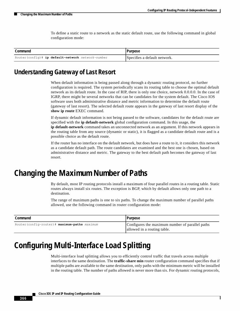
To define a static route to a network as the static default route, use the following command in globalconfiguration mode:
Understanding Gateway of Last ResortWhen default information is being passed along through a dynamic routing protocol, no furtherconfiguration is required. The system periodically scans its routing table to choose the optimal defaultnetwork as its default route. In the case of RIP, there is only one choice, network 0.0.0.0. In the case ofIGRP, there might be several networks that can be candidates for the system default. The Cisco IOSsoftware uses both administrative distance and metric information to determine the default route(gateway of last resort). The selected default route appears in the gateway of last resort display of theshow ip route EXEC command.
If dynamic default information is not being passed to the software, candidates for the default route arespecified with theip default-network global configuration command. In this usage, theip default-network command takes an unconnected network as an argument. If this network appears inthe routing table from any source (dynamic or static), it is flagged as a candidate default route and is apossible choice as the default route.
If the router has no interface on the default network, but does have a route to it, it considers this networkas a candidate default path. The route candidates are examined and the best one is chosen, based onadministrative distance and metric. The gateway to the best default path becomes the gateway of lastresort.
Changing the Maximum Number of PathsBy default, most IP routing protocols install a maximum of four parallel routes in a routing table. Staticroutes always install six routes. The exception is BGP, which by default allows only one path to adestination.
The range of maximum paths is one to six paths. To change the maximum number of parallel pathsallowed, use the following command in router configuration mode:
Configuring Multi-Interface Load SplittingMulti-interface load splitting allows you to efficiently control traffic that travels across multipleinterfaces to the same destination. Thetraffic-share min router configuration command specifies that ifmultiple paths are available to the same destination, only paths with the minimum metric will be installedin the routing table. The number of paths allowed is never more than six. For dynamic routing protocols,
Command PurposeRouter(config)# ip default-network network-number Specifies a default network.
Command PurposeRouter(config-router)# maximum-paths maximum Configures the maximum number of parallel paths
allowed in a routing table.

Configuring IP Routing Protocol-Independent FeaturesRedistributing Routing Information
367Cisco IOS IP and IP Routing Configuration Guide
the number of paths is controlled by themaximum-paths router configuration command. The staticroute source can always install six paths. If more paths are available, the extra paths are discarded. Ifsome installed paths are removed from the routing table, pending routes are added automatically.
When thetraffic-share min command is used with theacross-interfaceskeyword, an attempt is madeto use as many different interfaces as possible to forward traffic to the same destination. When themaximum path limit has been reached and a new path is installed, the router compares the installed paths.For example, if path X references the same interface as path Y and the new path uses a different interface,path X is removed and the new path is installed.
To configure traffic that is distributed among multiple routes of unequal cost for equal cost paths acrossmultiple interfaces, use the following command in router configuration mode:
Redistributing Routing InformationIn addition to running multiple routing protocols simultaneously, the Cisco IOS software can redistributeinformation from one routing protocol to another. For example, you can instruct the software toreadvertise IGRP-derived routes using RIP, or to readvertise static routes using the IGRP protocol.Redistributing information from one routing protocol to another applies to all of the IP-based routingprotocols.
You also can conditionally control the redistribution of routes between routing domains by defining amethod known asroute maps between the two domains.
The following four tables list tasks associated with route redistribution. Although redistribution is aprotocol-independent feature, some of thematch andsetcommands are specific to a particular protocol.
To define a route map for redistribution, use the following command in global configuration mode:
One or morematch commands and one or moreset commands typically follow aroute-map globalconfiguration command. If there are nomatch commands, then everything matches. If there are nosetcommands, nothing is done (other than the match). Therefore, you need at least onematch or setcommand.
To define conditions for redistributing routes from one routing protocol into another, use at least one ofthe following commands in route-map configuration mode, as needed:
Command PurposeRouter(config-router)# traffic-share min{ across-interfaces }
Configures multi-interface load splitting across differentinterfaces with equal cost paths.
Command PurposeRouter(config)# route-map map-tag [ permit | deny ][ sequence-number ]
Defines any route maps needed to controlredistribution.
Command PurposeRouter(config-route-map)# match as-path path-list-number Matches a BGP autonomous system path access list.
Router(config-route-map)# match community-listcommunity-list-number [ exact ]
Matches a BGP community list.
Configuring IP Routing Protocol-Independent FeaturesRedistributing Routing Information
368Cisco IOS IP and IP Routing Configuration Guide
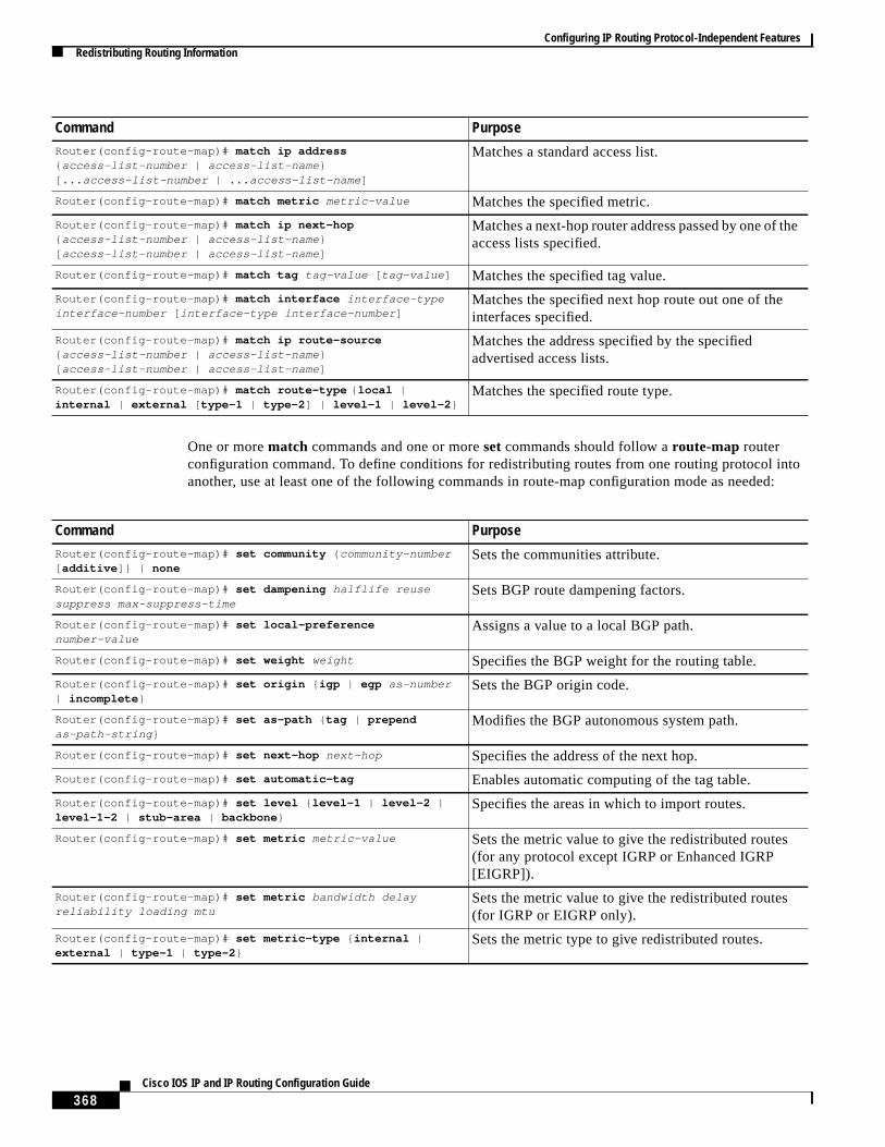
One or morematch commands and one or moreset commands should follow aroute-map routerconfiguration command. To define conditions for redistributing routes from one routing protocol intoanother, use at least one of the following commands in route-map configuration mode as needed:
Router(config-route-map)# match ip address{ access-list-number | access-list-name }[... access-list-number | ... access-list-name ]
Matches a standard access list.
Router(config-route-map)# match metric metric-value Matches the specified metric.
Router(config-route-map)# match ip next-hop{ access-list-number | access-list-name }[ access-list-number | access-list-name ]
Matches a next-hop router address passed by one of theaccess lists specified.
Router(config-route-map)# match tag tag-value [ tag-value ] Matches the specified tag value.
Router(config-route-map)# match interface interface-typeinterface-number [ interface-type interface-number ]
Matches the specified next hop route out one of theinterfaces specified.
Router(config-route-map)# match ip route-source{ access-list-number | access-list-name }[ access-list-number | access-list-name ]
Matches the address specified by the specifiedadvertised access lists.
Router(config-route-map)# match route-type { local |internal | external [ type-1 | type-2 ] | level-1 | level-2 }
Matches the specified route type.
Command Purpose
Command PurposeRouter(config-route-map)# set community { community-number[ additive ]} | none
Sets the communities attribute.
Router(config-route-map)# set dampening halflife reusesuppress max-suppress-time
Sets BGP route dampening factors.
Router(config-route-map)# set local-preferencenumber-value
Assigns a value to a local BGP path.
Router(config-route-map)# set weight weight Specifies the BGP weight for the routing table.
Router(config-route-map)# set origin { igp | egp as-number| incomplete }
Sets the BGP origin code.
Router(config-route-map)# set as-path { tag | prependas-path-string }
Modifies the BGP autonomous system path.
Router(config-route-map)# set next-hop next-hop Specifies the address of the next hop.
Router(config-route-map)# set automatic-tag Enables automatic computing of the tag table.
Router(config-route-map)# set level { level-1 | level-2 |level-1-2 | stub-area | backbone }
Specifies the areas in which to import routes.
Router(config-route-map)# set metric metric-value Sets the metric value to give the redistributed routes(for any protocol except IGRP or Enhanced IGRP[EIGRP]).
Router(config-route-map)# set metric bandwidth delayreliability loading mtu
Sets the metric value to give the redistributed routes(for IGRP or EIGRP only).
Router(config-route-map)# set metric-type { internal |external | type-1 | type-2 }
Sets the metric type to give redistributed routes.

Configuring IP Routing Protocol-Independent FeaturesRedistributing Routing Information
369Cisco IOS IP and IP Routing Configuration Guide
See the “BGP Route Map Examples” section in the “Configuring BGP” chapter for examples of BGProute maps. See the “BGP Community with Route Maps Examples” section in the “Configuring BGP”chapter for examples of BGP communities and route maps.
To distribute routes from one routing domain into another and to control route redistribution, use thefollowing commands in router configuration mode:
The metrics of one routing protocol do not necessarily translate into the metrics of another. For example,the RIP metric is a hop count and the IGRP metric is a combination of five quantities. In such situations,an artificial metric is assigned to the redistributed route. Because of this unavoidable tampering withdynamic information, carelessly exchanging routing information between different routing protocols cancreate routing loops, which can seriously degrade network operation.
Understanding Supported Metric TranslationsThis section describes supported automatic metric translations between the routing protocols. Thefollowing descriptions assume that you have not defined a default redistribution metric that replacesmetric conversions:
• RIP can automatically redistribute static routes. It assigns static routes a metric of 1 (directlyconnected).
• BGP does not normally send metrics in its routing updates.
Router(config-route-map)# set metric-type internal Sets the Multi Exit Discriminator (MED) value onprefixes advertised to Exterior BGP neighbor to matchthe Interior Gateway Protocol (IGP) metric of the nexthop.
Router(config-route-map)# set tag tag-value Sets the tag value to associate with the redistributedroutes.
Command Purpose
Command Purpose
Step 1 Router(config-router)# redistribute protocol[ process-id ] { level-1 | level-1-2 | level-2 } [ metricmetric-value ] [ metric-type type-value ] [ matchinternal | external type-value ] [ tag tag-value ][ route-map map-tag ] [ subnets ]
Redistributes routes from one routing protocol toanother routing protocol.
Step 2 Router(config-router)# default-metric number Causes the current routing protocol to use the samemetric value for all redistributed routes (BGP, OSPF,RIP).
Step 3 Router(config-router)# default-metric bandwidthdelay reliability loading mtu
Causes the IGRP or Enhanced IGRP (EIGRP) routingprotocol to use the same metric value for allnon-IGRP redistributed routes.
Step 4 Router(config-router)# no default-information { in |out }
Disables the redistribution of default informationbetween IGRP processes, which is enabled bydefault.

Configuring IP Routing Protocol-Independent FeaturesFiltering Routing Information
370Cisco IOS IP and IP Routing Configuration Guide
• IGRP can automatically redistribute static routes and information from other IGRP-routedautonomous systems. IGRP assigns static routes a metric that identifies them as directly connected.IGRP does not change the metrics of routes derived from IGRP updates from other autonomoussystems.
• Note that any protocol can redistribute other routing protocols if a default metric is in effect.
Filtering Routing InformationTo filter routing protocol information performing the tasks in the following sections. The tasks in thefirst section are required; the tasks in the remaining sections are optional:
• Preventing Routing Updates Through an Interface (Required)
• Controlling the Advertising of Routes in Routing Updates (Optional)
• Controlling the Processing of Routing Updates (Optional)
• Filtering Sources of Routing Information (Optional)
Note When routes are redistributed between OSPF processes, no OSPF metrics are preserved.
Preventing Routing Updates Through an InterfaceTo prevent other routers on a local network from learning about routes dynamically, you can keep routingupdate messages from being sent through a router interface. Keeping routing update messages frombeing sent through a router interface prevents other systems on the interface from learning about routesdynamically. This feature applies to all IP-based routing protocols except BGP.
OSPF and IS-IS behave somewhat differently. In OSPF, the interface address you specify as passiveappears as a stub network in the OSPF domain. OSPF routing information is neither sent nor receivedthrough the specified router interface. In IS-IS, the specified IP addresses are advertised without actuallyrunning IS-IS on those interfaces.
To prevent routing updates through a specified interface, use the following command in routerconfiguration mode:
See the “Passive Interface Examples” section at the end of this chapter for examples of configuringpassive interfaces.
Command PurposeRouter(config-router)# passive-interfaceinterface-type interface-number
Suppresses the sending of routing updates through thespecified interface.

Configuring IP Routing Protocol-Independent FeaturesFiltering Routing Information
371Cisco IOS IP and IP Routing Configuration Guide
Configuring Default Passive Interfaces
In Internet service provider (ISP) and large enterprise networks, many of the distribution routers havemore than 200 interfaces. Before the introduction of the Default Passive Interface feature, there were twopossibilities for obtaining routing information from these interfaces:
• Configure a routing protocol such as OSPF on the backbone interfaces and redistribute connectedinterfaces.
• Configure the routing protocol on all interfaces and manually set most of them as passive.
Network managers may not always be able to summarize type 5 link-state advertisements (LSAs) at therouter level where redistribution occurs, as in the first possibility. Thus, a large number of type 5 LSAscan be flooded over the domain.
In the second possibility, large type 1 LSAs might be flooded into the area. The Area Border Router(ABR) creates type 3 LSAs, one for each type 1 LSA, and floods them to the backbone. It is possible,however, to have unique summarization at the ABR level, which will inject only one summary route intothe backbone, thereby reducing processing overhead.
The prior solution to this problem was to configure the routing protocol on all interfaces and manuallyset thepassive-interface router configuration command on the interfaces where adjacency was notdesired. But in some networks, this solution meant coding 200 or more passive interface statements.With the Default Passive Interface feature, this problem is solved by allowing all interfaces to be set aspassive by default using a singlepassive-interface default command, then configuring individualinterfaces where adjacencies are desired using theno passive-interface command.
Thus, the Default Passive Interface feature simplifies the configuration of distribution routers and allowsthe network manager to obtain routing information from the interfaces in large ISP and enterprisenetworks.
To set all interfaces as passive by default and then activate only those interfaces that need to haveadjacencies set, use the following commands beginning in global configuration mode:
See the section “Default Passive Interface Example” at the end of this chapter for an example of a defaultpassive interface.
To verify that interfaces on your network have been set to passive, you could enter a network monitoringcommand such as theshow ip ospf interface EXEC command, or you could verify the interfaces youenabled as active using a command such as theshow ip interface EXEC command.
Command Purpose
Step 1 Router(config)# router protocol Configures the routing protocol on the network.
Step 2 Router(config-router)# passive-interface default Sets all interfaces as passive by default.
Step 3 Router(config-router)# no passive-interfaceinterface-type
Activates only those interfaces that need to haveadjacencies set.
Step 4 Router(config-router)# network network-address[ options ]
Specifies the list of networks for the routing process.Thenetwork-address argument is an IP addresswritten in dotted decimal notation—172.24.101.14,for example.

Configuring IP Routing Protocol-Independent FeaturesFiltering Routing Information
372Cisco IOS IP and IP Routing Configuration Guide
Controlling the Advertising of Routes in Routing UpdatesTo prevent other routers from learning one or more routes, you can suppress routes from being advertisedin routing updates. Suppressing routes in route updates prevents other routers from learning theinterpretation of a particular device of one or more routes. You cannot specify an interface name inOSPF. When used for OSPF, this feature applies only to external routes.
To suppress routes from being advertised in routing updates, use the following command in routerconfiguration mode:
Controlling the Processing of Routing UpdatesYou might want to avoid processing certain routes listed in incoming updates. This feature does notapply to OSPF or IS-IS. To suppress routes in incoming updates, use the following command in routerconfiguration mode:
Filtering Sources of Routing InformationFiltering sources of routing information prioritizes routing information from different sources, becausesome pieces of routing information may be more accurate than others. An administrative distance is arating of the trustworthiness of a routing information source, such as an individual router or a group ofrouters. In a large network, some routing protocols and some routers can be more reliable than others assources of routing information. Also, when multiple routing processes are running in the same router forIP, it is possible for the same route to be advertised by more than one routing process. By specifyingadministrative distance values, you enable the router to intelligently discriminate between sources ofrouting information. The router will always pick the route whose routing protocol has the lowestadministrative distance.
To filter sources of routing information, use the following command in router configuration mode:
There are no general guidelines for assigning administrative distances because each network has its ownrequirements. You must determine a reasonable matrix of administrative distances for the network as awhole.Table 9 shows the default administrative distance for various routing information sources.
Command PurposeRouter(config-router)# distribute-list{ access-list-number | access-list-name } out[ interface-name | routing-process | as-number ]
Permits or denies routes from being advertised inrouting updates depending upon the action listed in theaccess list.
Command PurposeRouter(config-router)# distribute-list{ access-list-number | access-list-name } in[ interface-type interface-number ]
Suppresses routes listed in updates from beingprocessed.
Command PurposeRouter(config-router)# distance { ip-address { wildcard-mask}} [ ip-standard-list ] [ ip-extended ]
Filters on routing information sources.
Configuring IP Routing Protocol-Independent FeaturesEnabling Policy Routing (PBR)
373Cisco IOS IP and IP Routing Configuration Guide
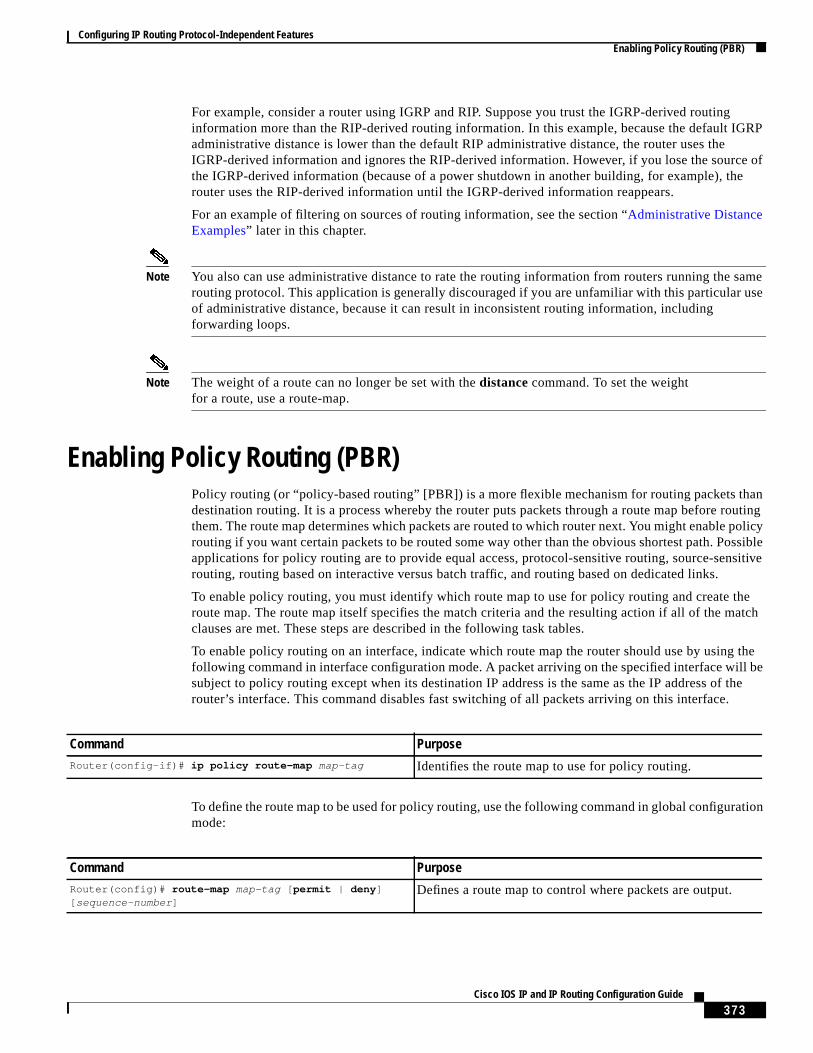
For example, consider a router using IGRP and RIP. Suppose you trust the IGRP-derived routinginformation more than the RIP-derived routing information. In this example, because the default IGRPadministrative distance is lower than the default RIP administrative distance, the router uses theIGRP-derived information and ignores the RIP-derived information. However, if you lose the source ofthe IGRP-derived information (because of a power shutdown in another building, for example), therouter uses the RIP-derived information until the IGRP-derived information reappears.
For an example of filtering on sources of routing information, see the section “Administrative DistanceExamples” later in this chapter.
Note You also can use administrative distance to rate the routing information from routers running the samerouting protocol. This application is generally discouraged if you are unfamiliar with this particular useof administrative distance, because it can result in inconsistent routing information, includingforwarding loops.
Note The weight of a route can no longer be set with thedistance command. To set the weightfor a route, use a route-map.
Enabling Policy Routing (PBR)Policy routing (or “policy-based routing” [PBR]) is a more flexible mechanism for routing packets thandestination routing. It is a process whereby the router puts packets through a route map before routingthem. The route map determines which packets are routed to which router next. You might enable policyrouting if you want certain packets to be routed some way other than the obvious shortest path. Possibleapplications for policy routing are to provide equal access, protocol-sensitive routing, source-sensitiverouting, routing based on interactive versus batch traffic, and routing based on dedicated links.
To enable policy routing, you must identify which route map to use for policy routing and create theroute map. The route map itself specifies the match criteria and the resulting action if all of the matchclauses are met. These steps are described in the following task tables.
To enable policy routing on an interface, indicate which route map the router should use by using thefollowing command in interface configuration mode. A packet arriving on the specified interface will besubject to policy routing except when its destination IP address is the same as the IP address of therouter’s interface. This command disables fast switching of all packets arriving on this interface.
To define the route map to be used for policy routing, use the following command in global configurationmode:
Command PurposeRouter(config-if)# ip policy route-map map-tag Identifies the route map to use for policy routing.
Command PurposeRouter(config)# route-map map-tag [ permit | deny ][ sequence-number ]
Defines a route map to control where packets are output.

Configuring IP Routing Protocol-Independent FeaturesEnabling Policy Routing (PBR)
374Cisco IOS IP and IP Routing Configuration Guide
To define the criteria by which packets are examined to learn if they will be policy-routed, use either oneor both of the following commands in route-map configuration mode. No match clause in the route mapindicates all packets.
To set the precedence and specify where the packets that pass the match criteria are output, use thefollowing commands in route-map configuration mode:
Note Theset ip next-hop andset ip default next-hop are similar commands but have a different order ofoperations. Configuring theset ip next-hopcommand causes the system to use policy routing first andthen use the routing table. Configuring theset ip default next-hopcauses the system to use the routingtable first and then policy route the specified next hop.
The precedence setting in the IP header determines whether, during times of high traffic, the packets willbe treated with more or less precedence than other packets. By default, the Cisco IOS software leavesthis value untouched; the header remains with the precedence value it had.
The precedence bits in the IP header can be set in the router when policy routing is enabled. When thepackets containing those headers arrive at another router, the packets are ordered for transmissionaccording to the precedence set, if the queueing feature is enabled. The router does not honor theprecedence bits if queueing is not enabled; the packets are sent in FIFO order.
You can change the precedence setting, using either a number or name. The names came from RFC 791,but are evolving. You can enable other features that use the values in theset ip precedence route-mapconfiguration command to determine precedence.Table 10 lists the possible numbers and theircorresponding name, from least important to most important.
Command PurposeRouter(config-route-map)# match length minimum-lengthmaximum-length
Matches the Level 3 length of the packet.
Router(config-route-map)# match ip address{ access-list-number | access-list-name }[ access-list-number | access-list-name ]
Matches the destination IP address that is permitted byone or more standard or extended access lists.
Command Purpose
Step 1 Router(config-route-map)# set ip precedence number | name Sets the precedence value in the IP header.
Step 2 Router(config-route-map)# set ip next-hop ip-address[ ip-address ]
Specifies the next hop to which to route thepacket.(It must be an adjacent router).
Step 3 Router(config-route-map)# set interface interface-typeinterface-number [... interface-type interface-number ]
Specifies the output interface for the packet.
Step 4 Router(config-route-map)# set ip default next-hopip-address [ ip-address ]
Specifies the next hop to which to route thepacket, if there is no explicit route for thisdestination.
Note Like theset ip next-hopcommand, theset ip default next-hopcommand needsto specify an adjacent router.
Step 5 Router(config-route-map)# set default interfaceinterface-type interface-number [... interface-typeinterface-number ]
Specifies the output interface for the packet, ifthere is no explicit route for this destination.

Configuring IP Routing Protocol-Independent FeaturesEnabling Policy Routing (PBR)
375Cisco IOS IP and IP Routing Configuration Guide
Theset commands can be used with each other. They are evaluated in the order shown in the previoustask table. A usable next hop implies an interface. Once the local router finds a next hop and a usableinterface, it routes the packet.
Preverifying Next-Hop AvailabilityIf the router is policy routing packets to the next hop and the next hop happens to be down, the routerwill try unsuccessfully to use Address Resolution Protocol (ARP) for the next hop (which is down). Thisbehavior will continue forever.
To prevent this situation, you can configure the router to first verify that the next hops of the route mapare CDP neighbors of the router before routing to that next hop.
This task is optional because some media or encapsulations do not support CDP, or it may not be a Ciscodevice that is sending the router traffic
To configure the route-map policy to verify that the next hop is available before the router attempts toroute traffic to it, use the following command in route-map configuration mode:
The set ip next-hop verify-availability has the following restrictions:
• It can cause some performance degradation due to CDP database lookup overhead per packet.
• CDP must be enabled on the interface.
Table 10 IP Precedence Values
Number Name
0 routine
1 priority
2 immediate
3 flash
4 flash-override
5 critical
6 internet
7 network
Command PurposeRouter(config-route-map)# set ip next-hopverify-availability
Causes the router to confirm that the next hop, specified in the routemap configuration, are active and available.
• This command relies on CDP to determine if the next hop is anactive CDP neighbor.
• If this command is not used, and the next hop is not available,the traffic will remain forever unrouted.
• If this command is used, and the next hop is not a CDPneighbor, the router looks to the subsequent next hop, if thereis one. If a subsequent next-hop is not defined, the packetssimply are not policy routed
Configuring IP Routing Protocol-Independent FeaturesEnabling Policy Routing (PBR)
376Cisco IOS IP and IP Routing Configuration Guide
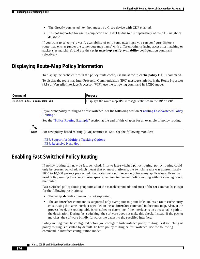
• The directly connected next hop must be a Cisco device with CDP enabled.
• It is not supported for use in conjunction with dCEF, due to the dependency of the CDP neighbordatabase.
If you want to selectively verify availability of only some next hops, you can configure differentroute-map entries (under the same route map name) with different criteria (using access list matching orpacket size matching), and use the set ip next-hop verify-availability configuration commandselectively.
Displaying Route-Map Policy InformationTo display the cache entries in the policy route cache, use theshow ip cache policy EXEC command.
To display the route map Inter Processor Communication (IPC) message statistics in the Route Processor(RP) or Versatile Interface Processor (VIP), use the following command in EXEC mode:
If you want policy routing to be fast switched, see the following section “Enabling Fast-Switched PolicyRouting.”
See the “Policy Routing Example” section at the end of this chapter for an example of policy routing.
Note For new policy-based routing (PBR) features in 12.4, see the following modules:
- PBR Support for Multiple Tracking Options- PBR Recursive Next Hop
Enabling Fast-Switched Policy RoutingIP policy routing can now be fast switched. Prior to fast-switched policy routing, policy routing couldonly be process switched, which meant that on most platforms, the switching rate was approximately1000 to 10,000 packets per second. Such rates were not fast enough for many applications. Users thatneed policy routing to occur at faster speeds can now implement policy routing without slowing downthe router.
Fast-switched policy routing supports all of thematch commands and most of thesetcommands, exceptfor the following restrictions:
• Theset ip default command is not supported.
• Theset interface command is supported only over point-to-point links, unless a route cache entryexists using the same interface specified in theset interfacecommand in the route map. Also, at theprocess level, the routing table is consulted to determine if the interface is on a reasonable path tothe destination. During fast switching, the software does not make this check. Instead, if the packetmatches, the software blindly forwards the packet to the specified interface.
Policy routing must be configured before you configure fast-switched policy routing. Fast switching ofpolicy routing is disabled by default. To have policy routing be fast switched, use the followingcommand in interface configuration mode:
Command PurposeRouter# show route-map ipc Displays the route map IPC message statistics in the RP or VIP.

Configuring IP Routing Protocol-Independent FeaturesManaging Authentication Keys
377Cisco IOS IP and IP Routing Configuration Guide
Enabling Local Policy RoutingPackets that are generated by the router are not normally policy routed. To enable local policy routingfor such packets, indicate which route map the router should use by using the following command inglobal configuration mode. All packets originating on the router will then be subject to local policyrouting.
Use theshow ip local policyEXEC command to display the route map used for local policy routing, ifone exists.
Managing Authentication KeysKey management is a method of controlling authentication keys used by routing protocols. Not allprotocols can use key management. Authentication keys are available for Director Response Protocol(DRP) Agent, Enhanced IGRP (EIGRP), and RIP Version 2.
Before you manage authentication keys, authentication must be enabled. See the appropriate protocolchapter to learn how to enable authentication for that protocol.
To manage authentication keys, define a key chain, identify the keys that belong to the key chain, andspecify how long each key is valid. Each key has its own key identifier (specified with thekey chainconfiguration command), which is stored locally. The combination of the key identifier and the interfaceassociated with the message uniquely identifies the authentication algorithm and Message Digest 5(MD5) authentication key in use.
You can configure multiple keys with lifetimes. Only one authentication packet is sent, regardless of howmany valid keys exist. The software examines the key numbers in order from lowest to highest, and usesthe first valid key it encounters. The lifetimes allow for overlap during key changes. Note that the routermust know the time. Refer to the Network Time Protocol (NTP) and calendar commands in the“Performing Basic System Management” chapter of theCisco IOS Configuration FundamentalsConfiguration Guide.
To manage authentication keys, use the following commands beginning in global configuration mode:
Command PurposeRouter(config-if)# ip route-cache policy Enables fast switching of policy routing.
Command PurposeRouter(config)# ip local policy route-map map-tag Identifies the route map to use for local policy routing.
Command Purpose
Step 1 Router(config)# key chain name-of-chain Identifies a key chain.
Step 2 Router(config-keychain)# key number Identifies the key number in key chainconfiguration mode.
Step 3 Router(config-keychain-key)# key-string text Identifies the key string in key chainconfiguration mode.
Configuring IP Routing Protocol-Independent FeaturesMonitoring and Maintaining the IP Network
378Cisco IOS IP and IP Routing Configuration Guide
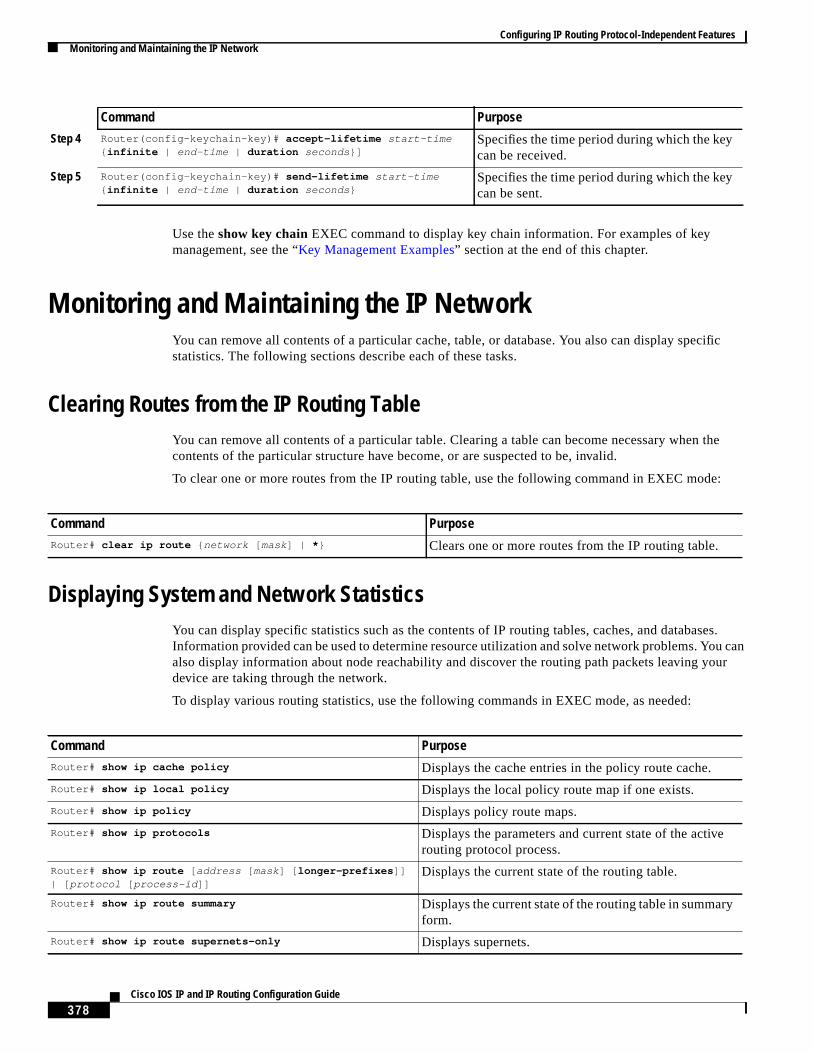
Use theshow key chain EXEC command to display key chain information. For examples of keymanagement, see the “Key Management Examples” section at the end of this chapter.
Monitoring and Maintaining the IP NetworkYou can remove all contents of a particular cache, table, or database. You also can display specificstatistics. The following sections describe each of these tasks.
Clearing Routes from the IP Routing TableYou can remove all contents of a particular table. Clearing a table can become necessary when thecontents of the particular structure have become, or are suspected to be, invalid.
To clear one or more routes from the IP routing table, use the following command in EXEC mode:
Displaying System and Network StatisticsYou can display specific statistics such as the contents of IP routing tables, caches, and databases.Information provided can be used to determine resource utilization and solve network problems. You canalso display information about node reachability and discover the routing path packets leaving yourdevice are taking through the network.
To display various routing statistics, use the following commands in EXEC mode, as needed:
Step 4 Router(config-keychain-key)# accept-lifetime start-time{ infinite | end-time | duration seconds }]
Specifies the time period during which the keycan be received.
Step 5 Router(config-keychain-key)# send-lifetime start-time{ infinite | end-time | duration seconds }
Specifies the time period during which the keycan be sent.
Command Purpose
Command PurposeRouter# clear ip route { network [ mask] | * } Clears one or more routes from the IP routing table.
Command PurposeRouter# show ip cache policy Displays the cache entries in the policy route cache.
Router# show ip local policy Displays the local policy route map if one exists.
Router# show ip policy Displays policy route maps.
Router# show ip protocols Displays the parameters and current state of the activerouting protocol process.
Router# show ip route [ address [ mask] [ longer-prefixes ]]| [ protocol [ process-id ]]
Displays the current state of the routing table.
Router# show ip route summary Displays the current state of the routing table in summaryform.
Router# show ip route supernets-only Displays supernets.
Configuring IP Routing Protocol-Independent FeaturesIP Routing Protocol-Independent Configuration Examples
379Cisco IOS IP and IP Routing Configuration Guide
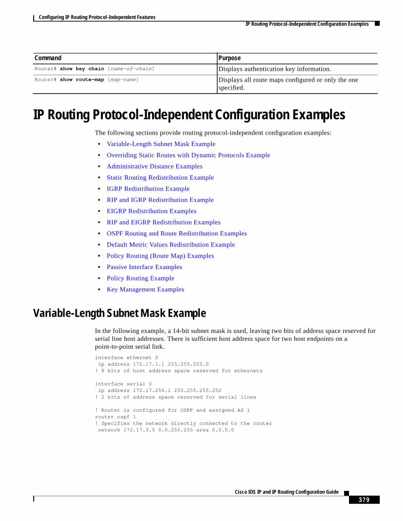
IP Routing Protocol-Independent Configuration ExamplesThe following sections provide routing protocol-independent configuration examples:
• Variable-Length Subnet Mask Example
• Overriding Static Routes with Dynamic Protocols Example
• Administrative Distance Examples
• Static Routing Redistribution Example
• IGRP Redistribution Example
• RIP and IGRP Redistribution Example
• EIGRP Redistribution Examples
• RIP and EIGRP Redistribution Examples
• OSPF Routing and Route Redistribution Examples
• Default Metric Values Redistribution Example
• Policy Routing (Route Map) Examples
• Passive Interface Examples
• Policy Routing Example
• Key Management Examples
Variable-Length Subnet Mask ExampleIn the following example, a 14-bit subnet mask is used, leaving two bits of address space reserved forserial line host addresses. There is sufficient host address space for two host endpoints on apoint-to-point serial link.
interface ethernet 0ip address 172.17.1.1 255.255.255.0
! 8 bits of host address space reserved for ethernets
interface serial 0ip address 172.17.254.1 255.255.255.252
! 2 bits of address space reserved for serial lines
! Router is configured for OSPF and assigned AS 1router ospf 1! Specifies the network directly connected to the router
network 172.17.0.0 0.0.255.255 area 0.0.0.0
Router# show key chain [ name-of-chain ] Displays authentication key information.
Router# show route-map [ map-name] Displays all route maps configured or only the onespecified.
Command Purpose

Configuring IP Routing Protocol-Independent FeaturesIP Routing Protocol-Independent Configuration Examples
380Cisco IOS IP and IP Routing Configuration Guide
Overriding Static Routes with Dynamic Protocols ExampleIn the following example, packets for network 10.0.0.0 from Router B (where the static route is installed)will be routed through 172.18.3.4 if a route with an administrative distance less than 110 is not available.Figure 62illustrates this example. The route learned by a protocol with an administrative distance of lessthan 110 might cause Router B to send traffic destined for network 10.0.0.0 via the alternatepath—through Router D.
ip route 10.0.0.0 255.0.0.0 172.18.3.4 110
Figure 62 Overriding Static Routes
Administrative Distance ExamplesIn the following example, therouter igrp global configuration command sets up IGRP routing inautonomous system 1. Thenetwork router configuration commands specify IGRP routing on networks192.168.7.0 and 172.16.0.0. The firstdistance router configuration command sets the defaultadministrative distance to 255, which instructs the router to ignore all routing updates from routers forwhich an explicit distance has not been set. The seconddistance command sets the administrativedistance to 90 for all routers on the Class C network 192.168.7.0. The thirddistancecommand sets theadministrative distance to 120 for the router with the address 172.16.1.3.
router igrp 1network 192.168.7.0network 172.16.0.0distance 255distance 90 192.168.7.0 0.0.0.255distance 120 172.16.1.3 0.0.0.0
The following example assigns the router with the address 192.168.7.18 an administrative distance of100 and all other routers on subnet 192.168.7.0 an administrative distance of 200:
distance 100 192.168.7.18 0.0.0.0distance 200 192.168.7.0 0.0.0.255
However, if you reverse the order of these two commands, all routers on subnet 192.168.7.0 are assignedan administrative distance of 200, including the router at address 192.168.7.18:
distance 200 192.168.7.0 0.0.0.255distance 100 192.168.7.18 0.0.0.0
Router C
Router D
Router B
Router A
172.18.3.4
12
69
a
10.0.0.0

Configuring IP Routing Protocol-Independent FeaturesIP Routing Protocol-Independent Configuration Examples
381Cisco IOS IP and IP Routing Configuration Guide
Assigning administrative distances is a problem unique to each network and is done in response to thegreatest perceived threats to the connected network. Even when general guidelines exist, the networkmanager must ultimately determine a reasonable matrix of administrative distances for the network as awhole.
In the following example, the distance value for IP routes learned is 90. Preference is given to these IProutes rather than routes with the default administrative distance value of 110.
router isisdistance 90 ip
Static Routing Redistribution ExampleIn the example that follows, three static routes are specified, two of which are to be advertised. The staticroutes are created by specifying theredistribute static router configuration command and thenspecifying an access list that allows only those two networks to be passed to the IGRP process. Anyredistributed static routes should be sourced by a single router to minimize the likelihood of creating arouting loop.
ip route 192.168.2.0 255.255.255.0 192.168.7.65ip route 192.168.5.0 255.255.255.0 192.168.7.65ip route 172.16.0.0 255.255.255.0 192.168.7.65access-list 3 permit 192.168.2.0access-list 3 permit 192.168.5.0!router igrp 1
network 192.168.7.0default-metric 10000 100 255 1 1500redistribute staticdistribute-list 3 out static
IGRP Redistribution ExampleEach IGRP routing process can provide routing information to only one autonomous system; theCisco IOS software must run a separate IGRP process and maintain a separate routing database for eachautonomous system that it services. However, you can transfer routing information between theserouting databases.
Suppose that the router has one IGRP routing process for network 10.0.0.0 in autonomous system 71 andanother IGRP routing process for network 192.168.7.0 in autonomous system 1, as the followingcommands specify:
router igrp 71network 10.0.0.0
router igrp 1network 192.168.7.0
To transfer a route to 192.168.7.0 into autonomous system 71 (without passing any other informationabout autonomous system 1), use the command in the following example:
router igrp 71redistribute igrp 1distribute-list 3 out igrp 1
access-list 3 permit 192.168.7.0
Configuring IP Routing Protocol-Independent FeaturesIP Routing Protocol-Independent Configuration Examples
382Cisco IOS IP and IP Routing Configuration Guide
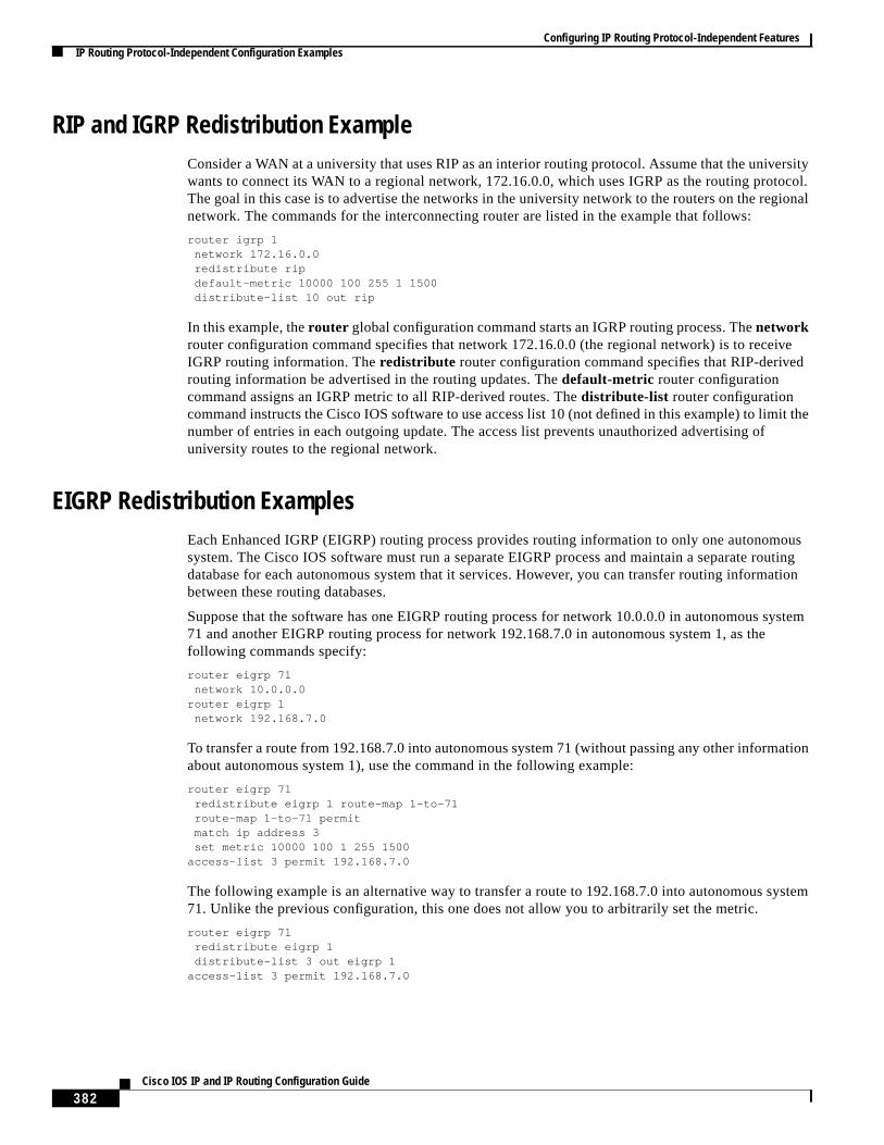
RIP and IGRP Redistribution ExampleConsider a WAN at a university that uses RIP as an interior routing protocol. Assume that the universitywants to connect its WAN to a regional network, 172.16.0.0, which uses IGRP as the routing protocol.The goal in this case is to advertise the networks in the university network to the routers on the regionalnetwork. The commands for the interconnecting router are listed in the example that follows:
router igrp 1network 172.16.0.0redistribute ripdefault-metric 10000 100 255 1 1500distribute-list 10 out rip
In this example, therouter global configuration command starts an IGRP routing process. Thenetworkrouter configuration command specifies that network 172.16.0.0 (the regional network) is to receiveIGRP routing information. Theredistribute router configuration command specifies that RIP-derivedrouting information be advertised in the routing updates. Thedefault-metric router configurationcommand assigns an IGRP metric to all RIP-derived routes. Thedistribute-list router configurationcommand instructs the Cisco IOS software to use access list 10 (not defined in this example) to limit thenumber of entries in each outgoing update. The access list prevents unauthorized advertising ofuniversity routes to the regional network.
EIGRP Redistribution ExamplesEach Enhanced IGRP (EIGRP) routing process provides routing information to only one autonomoussystem. The Cisco IOS software must run a separate EIGRP process and maintain a separate routingdatabase for each autonomous system that it services. However, you can transfer routing informationbetween these routing databases.
Suppose that the software has one EIGRP routing process for network 10.0.0.0 in autonomous system71 and another EIGRP routing process for network 192.168.7.0 in autonomous system 1, as thefollowing commands specify:
router eigrp 71network 10.0.0.0
router eigrp 1network 192.168.7.0
To transfer a route from 192.168.7.0 into autonomous system 71 (without passing any other informationabout autonomous system 1), use the command in the following example:
router eigrp 71redistribute eigrp 1 route-map 1-to-71route-map 1-to-71 permitmatch ip address 3set metric 10000 100 1 255 1500
access-list 3 permit 192.168.7.0
The following example is an alternative way to transfer a route to 192.168.7.0 into autonomous system71. Unlike the previous configuration, this one does not allow you to arbitrarily set the metric.
router eigrp 71redistribute eigrp 1distribute-list 3 out eigrp 1
access-list 3 permit 192.168.7.0
Configuring IP Routing Protocol-Independent FeaturesIP Routing Protocol-Independent Configuration Examples
383Cisco IOS IP and IP Routing Configuration Guide
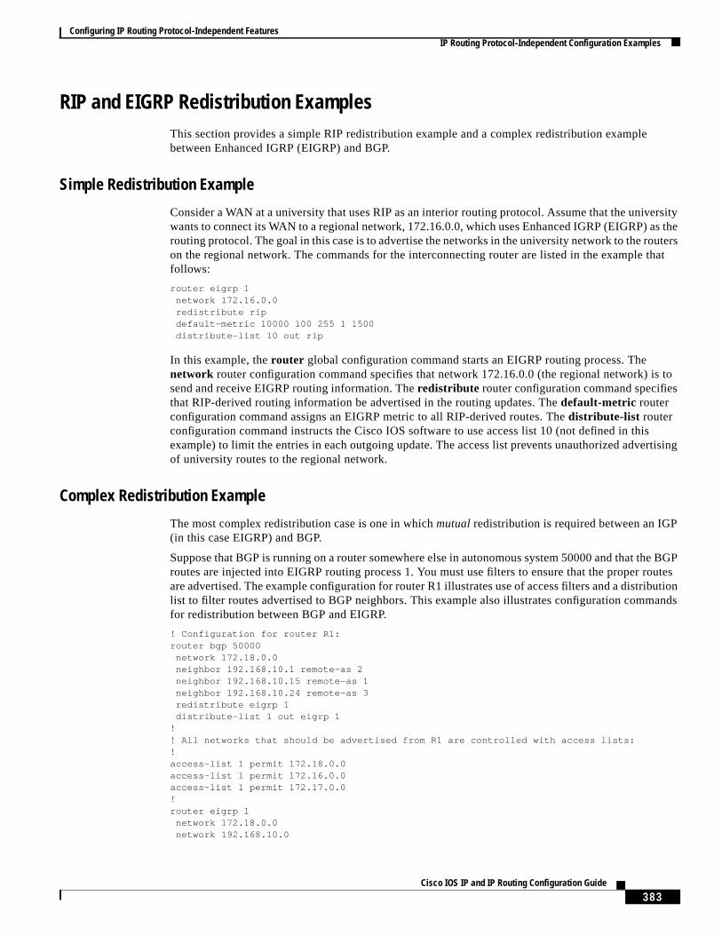
RIP and EIGRP Redistribution ExamplesThis section provides a simple RIP redistribution example and a complex redistribution examplebetween Enhanced IGRP (EIGRP) and BGP.
Simple Redistribution Example
Consider a WAN at a university that uses RIP as an interior routing protocol. Assume that the universitywants to connect its WAN to a regional network, 172.16.0.0, which uses Enhanced IGRP (EIGRP) as therouting protocol. The goal in this case is to advertise the networks in the university network to the routerson the regional network. The commands for the interconnecting router are listed in the example thatfollows:
router eigrp 1network 172.16.0.0redistribute ripdefault-metric 10000 100 255 1 1500distribute-list 10 out rip
In this example, therouter global configuration command starts an EIGRP routing process. Thenetwork router configuration command specifies that network 172.16.0.0 (the regional network) is tosend and receive EIGRP routing information. Theredistribute router configuration command specifiesthat RIP-derived routing information be advertised in the routing updates. Thedefault-metric routerconfiguration command assigns an EIGRP metric to all RIP-derived routes. Thedistribute-list routerconfiguration command instructs the Cisco IOS software to use access list 10 (not defined in thisexample) to limit the entries in each outgoing update. The access list prevents unauthorized advertisingof university routes to the regional network.
Complex Redistribution Example
The most complex redistribution case is one in whichmutualredistribution is required between an IGP(in this case EIGRP) and BGP.
Suppose that BGP is running on a router somewhere else in autonomous system 50000 and that the BGProutes are injected into EIGRP routing process 1. You must use filters to ensure that the proper routesare advertised. The example configuration for router R1 illustrates use of access filters and a distributionlist to filter routes advertised to BGP neighbors. This example also illustrates configuration commandsfor redistribution between BGP and EIGRP.
! Configuration for router R1:router bgp 50000
network 172.18.0.0neighbor 192.168.10.1 remote-as 2neighbor 192.168.10.15 remote-as 1neighbor 192.168.10.24 remote-as 3redistribute eigrp 1distribute-list 1 out eigrp 1
!! All networks that should be advertised from R1 are controlled with access lists:!access-list 1 permit 172.18.0.0access-list 1 permit 172.16.0.0access-list 1 permit 172.17.0.0!router eigrp 1
network 172.18.0.0network 192.168.10.0
Configuring IP Routing Protocol-Independent FeaturesIP Routing Protocol-Independent Configuration Examples
384Cisco IOS IP and IP Routing Configuration Guide
redistribute bgp 50000
OSPF Routing and Route Redistribution ExamplesOSPF typically requires coordination among many internal routers, ABRs, and Autonomous SystemBoundary Routers (ASBRs). At a minimum, OSPF-based routers can be configured with all defaultparameter values, with no authentication, and with interfaces assigned to areas. Three types of examplesfollow:
• The first examples are simple configurations illustrating basic OSPF commands.
• The second example illustrates a configuration for an internal router, ABR, and ASBRs within asingle, arbitrarily assigned, OSPF autonomous system.
• The third example illustrates a more complex configuration and the application of various toolsavailable for controlling OSPF-based routing environments.
Basic OSPF Configuration Examples
The following example illustrates a simple OSPF configuration that enables OSPF routing process 9000,attaches Ethernet interface 0 to area 0.0.0.0, and redistributes RIP into OSPF and OSPF into RIP:
interface ethernet 0ip address 172.16.1.1 255.255.255.0ip ospf cost 1
!interface ethernet 1
ip address 172.17.1.1 255.255.255.0!router ospf 9000
network 172.16.0.0 0.0.255.255 area 0.0.0.0redistribute rip metric 1 subnets
!router rip
network 172.17.0.0redistribute ospf 9000default-metric 1
The following example illustrates the assignment of four area IDs to four IP address ranges. In theexample, OSPF routing process 1 is initialized, and four OSPF areas are defined: 10.9.50.0, 2, 3, and 0.Areas 10.9.50.0, 2, and 3 mask specific address ranges, whereas area 0 enables OSPF forall othernetworks.
router ospf 1network 172.16.20.0 0.0.0.255 area 10.9.50.0network 172.16.0.0 0.0.255.255 area 2network 172.17.10.0 0.0.0.255 area 3network 0.0.0.0 255.255.255.255 area 0
!! Ethernet interface 0 is in area 10.9.50.0:interface ethernet 0
ip address 172.16.20.5 255.255.255.0!! Ethernet interface 1 is in area 2:interface ethernet 1
ip address 172.16.1.5 255.255.255.0!! Ethernet interface 2 is in area 2:interface ethernet 2
ip address 172.17.2.5 255.255.255.0
Configuring IP Routing Protocol-Independent FeaturesIP Routing Protocol-Independent Configuration Examples
385Cisco IOS IP and IP Routing Configuration Guide
!! Ethernet interface 3 is in area 3:interface ethernet 3
ip address 172.18.10.5 255.255.255.0!! Ethernet interface 4 is in area 0:interface ethernet 4
ip address 172.19.1.1 255.255.255.0!! Ethernet interface 5 is in area 0:interface ethernet 5
ip address 10.1.0.1 255.255.0.0
Eachnetwork router configuration command is evaluated sequentially, so the specific order of thesecommands in the configuration is important. The Cisco IOS software sequentially evaluates theaddress/wildcard-mask pair for each interface. See the “IP Routing Protocols Commands” chapter of theCisco IOS IP Command Reference, Volume 2 of 3: Routing Protocolspublication for more information.
Consider the firstnetwork command. Area ID 10.9.50.0 is configured for the interface on which subnet172.18.20.0 is located. Assume that a match is determined for Ethernet interface 0. Ethernet interface 0is attached to Area 10.9.50.0 only.
The secondnetwork command is evaluated next. For Area 2, the same process is then applied to allinterfaces (except Ethernet interface 0). Assume that a match is determined for Ethernet interface 1.OSPF is then enabled for that interface and Ethernet 1 is attached to Area 2.
This process of attaching interfaces to OSPF areas continues for allnetwork commands. Note that thelastnetwork command in this example is a special case. With this command, all available interfaces (notexplicitly attached to another area) are attached to Area 0.
Internal Router, ABR, and ASBRs Configuration Example
Figure 63 provides a general network map that illustrates a sample configuration for several routerswithin a single OSPF autonomous system.

Configuring IP Routing Protocol-Independent FeaturesIP Routing Protocol-Independent Configuration Examples
386Cisco IOS IP and IP Routing Configuration Guide
Figure 63 Example OSPF Autonomous System Network Map
In this configuration, five routers are configured in OSPF autonomous system 1:
• Router A and Router B are both internal routers within area 1.
• Router C is an OSPF ABR. Note that for Router C, area 1 is assigned to E3 and Area 0 is assignedto S0.
• Router D is an internal router in area 0 (backbone area). In this case, bothnetwork routerconfiguration commands specify the same area (area 0, or the backbone area).
• Router E is an OSPF ASBR. Note that BGP routes are redistributed into OSPF and that these routesare advertised by OSPF.
E1 E2
E3
E5
S2
S1
E4
Interface address:192.168.1.1
Interface address:192.168.1.2
Interface address:192.168.1.3
Network: 192.168.1.0
Network: 192.168.2.0
Network: 10.0.0.0
Interface address:10.0.0.4
Interface address:172.16.1.5
Interface address:10.0.0.5
Network: 172.16.1.0
Remote address:172.16.1.6in autonomoussystem 60000
Area 1
Area 0
OSPF domain (BGP autonomous system 50000)
S10
30a
Interface address:192.168.2.4
S0 Interface address:192.168.2.3
Router E
Router D
Router C
Router BRouter A

Configuring IP Routing Protocol-Independent FeaturesIP Routing Protocol-Independent Configuration Examples
387Cisco IOS IP and IP Routing Configuration Guide
Note It is not necessary to include definitions of all areas in an OSPF autonomous system in the configurationof all routers in the autonomous system. You must define only thedirectly connected areas. In theexample that follows, routes in Area 0 are learned by the routers in area 1 (Router A and Router B) whenthe ABR (Router C) injects summary LSAs into area 1.
Autonomous system 60000 is connected to the outside world via the BGP link to the external peer at IPaddress 172.16.1.6.
Following is the example configuration for the general network map shown inFigure 63.
Router A Configuration—Internal Routerinterface ethernet 1
ip address 192.168.1.1 255.255.255.0
router ospf 1network 192.168.1.0 0.0.0.255 area 1
Router B Configuration—Internal Routerinterface ethernet 2
ip address 192.168.1.2 255.255.255.0
router ospf 1network 192.168.1.0 0.0.0.255 area 1
Router C Configuration—ABRinterface ethernet 3
ip address 192.168.1.3 255.255.255.0
interface serial 0ip address 192.168.2.3 255.255.255.0
router ospf 1network 192.168.1.0 0.0.0.255 area 1network 192.168.2.0 0.0.0.255 area 0
Router D Configuration—Internal Routerinterface ethernet 4
ip address 10.0.0.4 255.0.0.0
interface serial 1ip address 192.168.2.4 255.255.255.0
router ospf 1network 192.168.2.0 0.0.0.255 area 0network 10.0.0.0 0.255.255.255 area 0
Router E Configuration—ASBRinterface ethernet 5
ip address 10.0.0.5 255.0.0.0
interface serial 2ip address 172.16.1.5 255.255.0.0
router ospf 1network 10.0.0.0 0.255.255.255 area 0redistribute bgp 50000 metric 1 metric-type 1

Configuring IP Routing Protocol-Independent FeaturesIP Routing Protocol-Independent Configuration Examples
388Cisco IOS IP and IP Routing Configuration Guide
router bgp 50000network 192.168.0.0network 10.0.0.0neighbor 172.16.1.6 remote-as 60000
Complex OSPF Configuration Example
The following example configuration accomplishes several tasks in setting up an ABR. These tasks canbe split into two general categories:
• Basic OSPF configuration
• Route redistribution
The specific tasks outlined in this configuration are detailed briefly in the following descriptions.Figure 64 illustrates the network address ranges and area assignments for the interfaces.
Figure 64 Interface and Area Specifications for OSPF Configuration Example
The basic configuration tasks in this example are as follows:
• Configure address ranges for Ethernet interface 0 through Ethernet interface 3.
• Enable OSPF on each interface.
• Set up an OSPF authentication password for each area and network.
• Assign link-state metrics and other OSPF interface configuration options.
• Create astub areawith area ID 10.0.0.0. (Note that theauthentication andstub options of thearearouter configuration command are specified with separatearea command entries, but they can bemerged into a singlearea command.)
• Specify the backbone area (area 0).
Configuration tasks associated with redistribution are as follows:
• Redistribute IGRP and RIP into OSPF with various options set (includingmetric-type, metric, tag,andsubnet).
• Redistribute IGRP and OSPF into RIP.
The following is an example OSPF configuration:
Router A
S10
31a
E3 E1
E2
E0
Network address range:192.168.110.0 through 192.168.110.255Area ID: 192.168.110.0
Network address range:10.56.0.0 through 10.56.255.255Area ID: 10.0.0.0Configured as stub area
Network address range:172.19.254.0 through 172.19.254.255Area ID: 0Configured as backbone area
Network address range:172.19.251.0 through 172.19.251.255Area ID: 0Configured as backbone area
Configuring IP Routing Protocol-Independent FeaturesIP Routing Protocol-Independent Configuration Examples
389Cisco IOS IP and IP Routing Configuration Guide
interface ethernet 0ip address 192.168.110.201 255.255.255.0ip ospf authentication-key abcdefghip ospf cost 10
!interface ethernet 1
ip address 172.19.251.201 255.255.255.0ip ospf authentication-key ijklmnopip ospf cost 20ip ospf retransmit-interval 10ip ospf transmit-delay 2ip ospf priority 4
!interface ethernet 2
ip address 172.19.254.201 255.255.255.0ip ospf authentication-key abcdefghip ospf cost 10
!interface ethernet 3
ip address 10.0.0.201 255.255.0.0ip ospf authentication-key ijklmnopip ospf cost 20ip ospf dead-interval 80
In the following configuration, OSPF is on network 172.19.0.0:
router ospf 1network 10.0.0.0 0.255.255.255 area 10.0.0.0network 192.168.110.0 0.0.0.255 area 192.168.110.0network 172.19.0.0 0.0.255.255 area 0area 0 authenticationarea 10.0.0.0 stubarea 10.0.0.0 authenticationarea 10.0.0.0 default-cost 20area 192.168.110.0 authenticationarea 10.0.0.0 range 10.0.0.0 255.0.0.0area 192.168.110.0 range 192.168.110.0 255.255.255.0area 0 range 172.19.251.0 255.255.255.0area 0 range 172.19.254.0 255.255.255.0
redistribute igrp 200 metric-type 2 metric 1 tag 200 subnetsredistribute rip metric-type 2 metric 1 tag 200
In the following configuration IGRP autonomous system 1 is on 172.19.0.0:
router igrp 1network 172.19.0.0
!! RIP for 192.168.110.0!router rip
network 192.168.110.0redistribute igrp 1 metric 1redistribute ospf 201 metric 1
Configuring IP Routing Protocol-Independent FeaturesIP Routing Protocol-Independent Configuration Examples
390Cisco IOS IP and IP Routing Configuration Guide
Default Metric Values Redistribution ExampleThe following example shows a router in autonomous system 1 using both RIP and IGRP. The exampleadvertises IGRP-derived routes using RIP and assigns the IGRP-derived routes a RIP metric of 10.
router ripdefault-metric 10redistribute igrp 1
Policy Routing (Route Map) ExamplesThe examples in this section illustrate the use of redistribution, with and without route maps. Examplesfrom both the IP and Connectionless Network Service (CLNS) routing protocols are given.
The following example redistributes all OSPF routes into IGRP:
router igrp 1redistribute ospf 110
The following example redistributes RIP routes with a hop count equal to 1 into OSPF. These routes willbe redistributed into OSPF as external LSAs with a metric of 5, metric a type of type 1, and a tag equalto 1.
router ospf 1redistribute rip route-map rip-to-ospf
!route-map rip-to-ospf permit
match metric 1set metric 5set metric-type type1set tag 1
The following example redistributes OSPF learned routes with tag 7 as a RIP metric of 15:
router ripredistribute ospf 1 route-map 5
!route-map 5 permit
match tag 7set metric 15
The following example redistributes OSPF intra-area and interarea routes with next hop routers on serialinterface 0 into BGP with an INTER_AS metric of 5:
router bgp 50000redistribute ospf 1 route-map 10
!route-map 10 permit
match route-type internalmatch interface serial 0set metric 5
The following example redistributes two types of routes into the integrated IS-IS routing table(supporting both IP and CLNS). The first type is OSPF external IP routes with tag 5; these routes areinserted into Level 2 IS-IS link-state packets (LSPs) with a metric of 5. The second type is ISO-IGRPderived CLNS prefix routes that match CLNS access list 2000; these routes will be redistributed intoIS-IS as Level 2 LSPs with a metric of 30.
router isisredistribute ospf 1 route-map 2

Configuring IP Routing Protocol-Independent FeaturesIP Routing Protocol-Independent Configuration Examples
391Cisco IOS IP and IP Routing Configuration Guide
redistribute iso-igrp nsfnet route-map 3!route-map 2 permit
match route-type externalmatch tag 5set metric 5set level level-2
!route-map 3 permit
match address 2000set metric 30
With the following configuration, OSPF external routes with tags 1, 2, 3, and 5 are redistributed into RIPwith metrics of 1, 1, 5, and 5, respectively. The OSPF routes with a tag of 4 are not redistributed.
router ripredistribute ospf 1 route-map 1
!route-map 1 permit
match tag 1 2set metric 1
!route-map 1 permit
match tag 3set metric 5
!route-map 1 deny
match tag 4!route map 1 permit
match tag 5set metric 5
Given the following configuration, a RIP learned route for network 172.18.0.0 and an ISO-IGRP learnedroute with prefix 49.0001.0002 will be redistributed into an IS-IS Level 2 LSP with a metric of 5:
router isisredistribute rip route-map 1redistribute iso-igrp remote route-map 1
!route-map 1 permit
match ip address 1match clns address 2set metric 5set level level-2
!access-list 1 permit 172.18.0.0 0.0.255.255
clns filter-set 2 permit 49.0001.0002...
The following configuration example illustrates how a route map is referenced by thedefault-information router configuration command. This type of reference is calledconditional defaultorigination. OSPF will originate the default route (network 0.0.0.0) with a type 2 metric of 5 if172.20.0.0 is in the routing table.
route-map ospf-default permitmatch ip address 1set metric 5set metric-type type-2
!access-list 1 172.20.0.0 0.0.255.255!router ospf 1
default-information originate route-map ospf-default
Configuring IP Routing Protocol-Independent FeaturesIP Routing Protocol-Independent Configuration Examples
392Cisco IOS IP and IP Routing Configuration Guide
See more route map examples in the “BGP Route Map Examples” and“BGP Community with RouteMaps Examples” sections of the 12.4 BGP documentation.
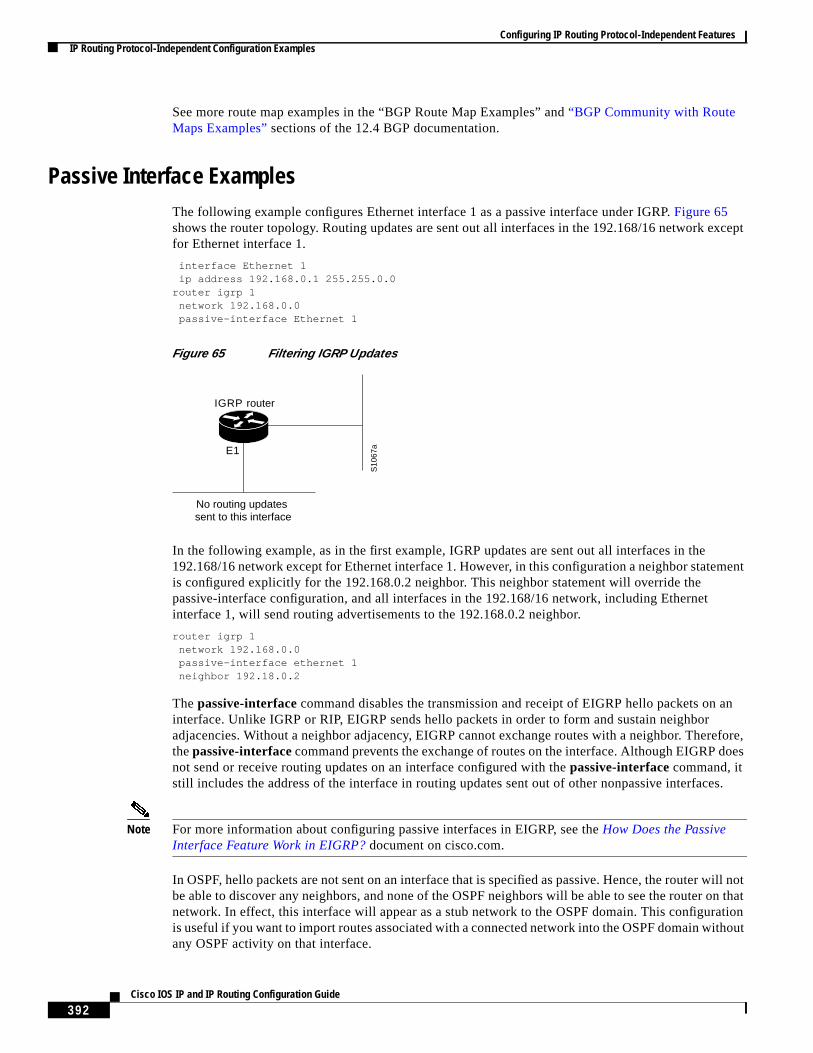
Passive Interface ExamplesThe following example configures Ethernet interface 1 as a passive interface under IGRP.Figure 65shows the router topology. Routing updates are sent out all interfaces in the 192.168/16 network exceptfor Ethernet interface 1.
interface Ethernet 1ip address 192.168.0.1 255.255.0.0
router igrp 1network 192.168.0.0passive-interface Ethernet 1
Figure 65 Filtering IGRP Updates
In the following example, as in the first example, IGRP updates are sent out all interfaces in the192.168/16 network except for Ethernet interface 1. However, in this configuration a neighbor statementis configured explicitly for the 192.168.0.2 neighbor. This neighbor statement will override thepassive-interface configuration, and all interfaces in the 192.168/16 network, including Ethernetinterface 1, will send routing advertisements to the 192.168.0.2 neighbor.
router igrp 1network 192.168.0.0passive-interface ethernet 1neighbor 192.18.0.2
Thepassive-interface command disables the transmission and receipt of EIGRP hello packets on aninterface. Unlike IGRP or RIP, EIGRP sends hello packets in order to form and sustain neighboradjacencies. Without a neighbor adjacency, EIGRP cannot exchange routes with a neighbor. Therefore,thepassive-interfacecommand prevents the exchange of routes on the interface. Although EIGRP doesnot send or receive routing updates on an interface configured with thepassive-interface command, itstill includes the address of the interface in routing updates sent out of other nonpassive interfaces.
Note For more information about configuring passive interfaces in EIGRP, see theHow Does the PassiveInterface Feature Work in EIGRP?document on cisco.com.
In OSPF, hello packets are not sent on an interface that is specified as passive. Hence, the router will notbe able to discover any neighbors, and none of the OSPF neighbors will be able to see the router on thatnetwork. In effect, this interface will appear as a stub network to the OSPF domain. This configurationis useful if you want to import routes associated with a connected network into the OSPF domain withoutany OSPF activity on that interface.
IGRP router
S10
67aE1
No routing updates sent to this interface
Configuring IP Routing Protocol-Independent FeaturesIP Routing Protocol-Independent Configuration Examples
393Cisco IOS IP and IP Routing Configuration Guide
Thepassive-interfacerouter configuration command is typically used when the wildcard specificationon thenetwork router configuration command configures more interfaces than is desirable. Thefollowing configuration causes OSPF to run on all subnets of 172.18.0.0:
interface ethernet 0ip address 172.18.1.1 255.255.255.0
interface ethernet 1ip address 172.18.2.1 255.255.255.0
interface ethernet 2ip address 172.18.3.1 255.255.255.0
!router ospf 1
network 172.18.0.0 0.0.255.255 area 0
If you do not want OSPF to run on 172.18.3.0, enter the following commands:
router ospf 1network 172.18.0.0 0.0.255.255 area 0passive-interface ethernet 2
Default Passive Interface Example
The following example configures the network interfaces, sets all interfaces that are running OSPF aspassive, and then enables serial interface 0:
interface Ethernet 0 ip address 172.19.64.38 255.255.255.0 secondary ip address 172.19.232.70 255.255.255.240 no ip directed-broadcast!interface Serial 0 ip address 172.24.101.14 255.255.255.252 no ip directed-broadcast no ip mroute-cache!interface TokenRing0 ip address 172.20.10.4 255.255.255.0 no ip directed-broadcast no ip mroute-cache ring-speed 16!router ospf 1 passive-interface default no passive-interface Serial0 network 172.16.10.0 0.0.0.255 area 0 network 172.19.232.0 0.0.0.255 area 4 network 172.24.101.0 0.0.0.255 area 4
Policy Routing ExampleThe following example provides two sources with equal access to two different service providers.Packets that arrive on asynchronous interface 1 from the source 10.1.1.1 are sent to the router at172.16.6.6 if the router has no explicit route for the destination of the packet. Packets that arrive fromthe source 172.17.2.2 are sent to the router at 192.168.7.7 if the router has no explicit route for thedestination of the packet. All other packets for which the router has no explicit route to the destinationare discarded.
access-list 1 permit ip 10.1.1.1access-list 2 permit ip 172.17.2.2!
Configuring IP Routing Protocol-Independent FeaturesIP Routing Protocol-Independent Configuration Examples
394Cisco IOS IP and IP Routing Configuration Guide
interface async 1ip policy route-map equal-access
!route-map equal-access permit 10
match ip address 1set ip default next-hop 172.16.6.6
route-map equal-access permit 20match ip address 2set ip default next-hop 192.168.7.7
route-map equal-access permit 30set default interface null0
Key Management ExamplesThe following example configures a key chain named trees. In this example, the software will alwaysaccept and send willow as a valid key. The key chestnut will be accepted from 1:30 p.m. to 3:30 p.m.and be sent from 2:00 p.m. to 3:00 p.m. The overlap allows for migration of keys or discrepancy in theset time of the router. Likewise, the key birch immediately follows chestnut, and there is a 30-minuteleeway on each side to handle time-of-day differences.
interface ethernet 0ip rip authentication key-chain treesip rip authentication mode md5
!router rip
network 172.19.0.0version 2
!key chain trees
key 1key-string willowkey 2key-string chestnutaccept-lifetime 13:30:00 Jan 25 1996 duration 7200send-lifetime 14:00:00 Jan 25 1996 duration 3600key 3key-string birchaccept-lifetime 14:30:00 Jan 25 1996 duration 7200send-lifetime 15:00:00 Jan 25 1996 duration 3600
The following example configures a key chain named trees:
key chain treeskey 1key-string willowkey 2key-string chesnutaccept-lifetime 00:00:00 Dec 5 1995 23:59:59 Dec 5 1995send-lifetime 06:00:00 Dec 5 1995 18:00:00 Dec 5 1995
!interface Ethernet0
ip address 172.19.104.75 255.255.255.0 secondaryip address 172.16.232.147 255.255.255.240ip rip authentication key-chain treesmedia-type 10BaseT
!interface Ethernet1
no ip addressshutdownmedia-type 10BaseT

Configuring IP Routing Protocol-Independent FeaturesIP Routing Protocol-Independent Configuration Examples
395Cisco IOS IP and IP Routing Configuration Guide
interface Fddi0ip address 10.1.1.1 255.255.255.0no keepalive
!interface Fddi1
ip address 172.16.1.1 255.255.255.0ip rip send version 1ip rip receive version 1no keepalive
!router rip
version 2network 172.19.0.0network 10.0.0.0network 172.16.0.0

Configuring IP Routing Protocol-Independent FeaturesIP Routing Protocol-Independent Configuration Examples
396Cisco IOS IP and IP Routing Configuration Guide