Configuring an ATM Interface
16
Configuring an ATM Interface Version: 3314 Copyright 2007-2010 ImageStream Internet Solutions, Inc., All rights Reserved.
Transcript of Configuring an ATM Interface

Configuring an ATM InterfaceVersion: 3314
Copyright 2007-2010 ImageStream Internet Solutions, Inc., All rights Reserved.


Table of ContentsRouter Installation and Configuration Manual/Configuring an ATM Interface.........................................1
WAN Port Uses.......................................................................................................................................1 Understanding the Network Interface Configuration File................................................................1 Configuring an ATM Master Interface............................................................................................1 Default ATM WAN Card Configuration.........................................................................................2 Customizing the Configuration........................................................................................................2 Setting ATM DS3/E3 Master Interface Parameters.........................................................................5 Setting ATM OC-3/OC-12 Master Interface Parameters.................................................................8 Configuring an ATM Subinterface...................................................................................................9
i

ii

Router Installation and ConfigurationManual/Configuring an ATM Interface
This chapter describes how to configure the ImageStream router ATM WAN interfaces and includesthe following topics:
WAN Port Uses◊ Understanding the Network Interface Configuration File◊ Configuring an ATM Master Interface◊ Default ATM Interface Configuration◊ Customizing the Configuration◊ Setting ATM Master Interface Parameters◊ Configuring an ATM Subinterface◊
Before configuring the WAN interface, you must make the appropriate cabling connection for yourneeds. Refer to the hardware installation guide for your ImageStream product for information onmaking the WAN connection. See the Technical Notes section on the ImageStream Web site or theCommand Reference for more detailed command descriptions, examples and instructions.
WAN Port Uses
WAN ports uses has been explained in Chapter 7, Router Installation and ConfigurationManual/Configuring a Synchronous Serial WAN Interface and in Chapter 31 Router Installation andConfiguration Manual/Basic Networking.
Understanding the Network Interface Configuration File
The wan.conf file is explained in detail in Chapter 5, Router Installation and ConfigurationManual/Configuring a LAN Interface, and in Chapter 31,Router Installation and ConfigurationManual/Basic Networking.
Configuring an ATM Master Interface
Asynchronous Transfer Mode (ATM) is a network protocol designed to facilitate the simultaneoustransfer of various types of traffic streams (voice, data, video) on public and private networks over thesame physical connection. By always using 53-byte cells, ATM simplifies the design of hardware,enabling it to quickly determine the destination address of each cell. This allows simple switching ofnetwork traffic at much higher speeds than are easily accomplished using protocols with variable sizesof transfer units, such as Frame Relay and TCP/IP.
ATM relies on the concepts of virtual paths and virtual circuits. A virtual path, represented by aspecific virtual path identifier (VPI), establishes a route between two devices in a network. Each VPIcan contain multiple virtual circuits, each represented by a virtual circuit identifier (VCI).
Router Installation and Configuration Manual/Configuring an ATM Interface 1
On an ImageStream router, each VPI/VCI pair is defined on the physical ATM interface as asubinterface. A subinterface is a logical (virtual) interface and is a part of a physical interface, such asan ATM DS3. Each physical ATM interface can be logically divided into as many as 64,000 differentlogical subinterfaces, depending on the card used.
The ATM port on each end of the connection must be configured prior to use. If your WAN interfacedoes not support ATM encapsulations, please See Chapter 7, Router Installation and ConfigurationManual/Configuring a Synchronous Serial WAN Interface or Chapter 8, Router Installation andConfiguration Manual/Configuring an Integrated CSU/DSU WAN Interface. Attempting toconfiguring non-ATM encapsulations on an ATM card will result in errors.
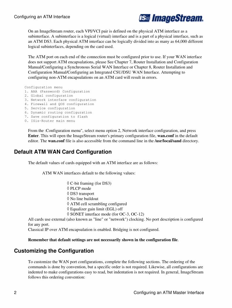
Configuration menu 1. AAA (Password) Configuration 2. Global configuration 3. Network interface configuration 4. Firewall and QOS configuration 5. Service configuration 6. Dynamic routing configuration 7. Save configuration to flash 0. ISis-Router main menu
From the :Configuration menu", select menu option 2, Network interface configuration, and pressEnter. This will open the ImageStream router's primary configuration file, wan.conf in the defaulteditor. The wan.conf file is also accessible from the command line in the /usr/local/sand directory.
Default ATM WAN Card Configuration
The default values of cards equipped with an ATM interface are as follows:
ATM WAN interfaces default to the following values:
C-bit framing (for DS3)◊ PLCP mode◊ DS3 transport◊ No line buildout◊ ATM cell scrambling configured◊ Equalizer gain limit (EGL) off◊ SONET interface mode (for OC-3, OC-12)◊
All cards use external (also known as "line" or "network") clocking. No port description is configuredfor any port.Classical IP over ATM encapsulation is enabled. Bridging is not configured.
Remember that default settings are not necessarily shown in the configuration file.
Customizing the Configuration
To customize the WAN port configurations, complete the following sections. The ordering of thecommands is done by convention, but a specific order is not required. Likewise, all configurations areindented to make configurations easy to read, but indentation is not required. In general, ImageStreamfollows this ordering convention:
Configuring an ATM Interface
2 Configuring an ATM Master Interface
Comments1. Port description2. Bandwidth scaling statement3. ATM interface settings4. Other optional settings5. IP address/netmask6. Secondary IP addresses/netmasks7. Subinterface configurations8.
Setting the Port Description
You can assign description to all WAN ports. Although this feature is optional, it may be particularlyuseful to assign names to facilitate administration. Setting a description does not change the operationor name of the port.
To assign a description to a port, enter this command in the wan.conf file in the Serial interfaceconfiguration section:
description string
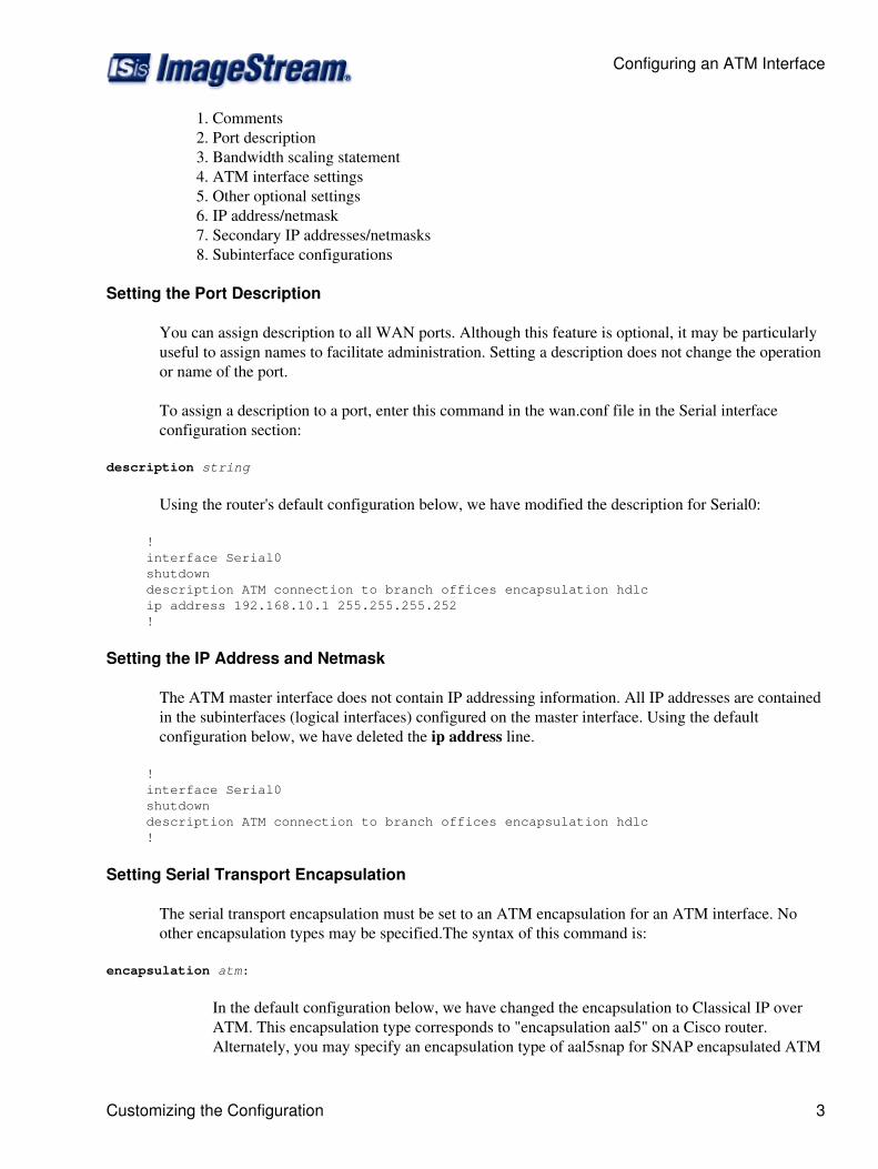
Using the router's default configuration below, we have modified the description for Serial0:
! interface Serial0 shutdown description ATM connection to branch offices encapsulation hdlc ip address 192.168.10.1 255.255.255.252 !
Setting the IP Address and Netmask
The ATM master interface does not contain IP addressing information. All IP addresses are containedin the subinterfaces (logical interfaces) configured on the master interface. Using the defaultconfiguration below, we have deleted the ip address line.
! interface Serial0 shutdown description ATM connection to branch offices encapsulation hdlc !
Setting Serial Transport Encapsulation
The serial transport encapsulation must be set to an ATM encapsulation for an ATM interface. Noother encapsulation types may be specified.The syntax of this command is:
encapsulation atm:
In the default configuration below, we have changed the encapsulation to Classical IP overATM. This encapsulation type corresponds to "encapsulation aal5" on a Cisco router.Alternately, you may specify an encapsulation type of aal5snap for SNAP encapsulated ATM
Configuring an ATM Interface
Customizing the Configuration 3

connections. See the ImageStream Technical Support Web site for additional ATMconfiguration examples.
! interface Serial0 shutdown description ATM connection to branch offices encapsulation atm !
Setting ATM DS3/E3 Circuit Transport
ImageStream's ATM DS3/E3 card supports either DS3 or E3 transport. By default, the card uses DS3transport. The transport type can be set using the transport command. The syntax of this commandis:
transport { ds3 | e3 }:
In the default configuration below, we have set the default transport type of DS3.
! interface Serial0 shutdown description ATM connection to branch offices encapsulation atm transport ds3 !
Setting ATM OC-3/OC-12 Circuit Transport
ImageStream's ATM OC-3 and OC-12 cards support either SONET or SDH as the underlyingnetwork transport for the ATM traffic. By default, the cards use SONET mode. The mode can be setusing the service-module { oc-3 | oc-12 } mode command and specifying a value of either sonet orsdh.
Enabling or Disabling a Serial Interface
To disable an interface, use the shutdown interface configuration command. Unlike other commandline interfaces, the wan.conf file does not require a "no" version of a command to reverse theoperation. Entering "no" followed by a command will be ignored by SAND.
By default, Serial0 is disabled in the default configuration below because the shutdown command hasbeen entered. Disabling a master interface will also disable all subinterfaces configured on the masterdevice.
! interface Serial0 shutdown description ATM connection to branch offices encapsulation atm transport ds3 !
Configuring an ATM Interface
4 Customizing the Configuration

To enable Serial0 in the configuration, remove the shutdown command. Do not use "no shutdown', asthis will be ignored by SAND. It is not necessary to enter "no" and a command to negate thecommand. Simply remove the command from the configuration file.
Adding Comments to a Serial Configuration
Comments may be added to the Serial configuration, or anywhere in the wan.conf file by inserting aline that begins with the # symbol. The contents of the line will be ignored by SAND. Comments maybe used to place contact information, ticket numbers, circuit IDs or any other information into thewan.conf file. There are no limits on the number or length of comments that may be inserted.
! interface Serial0 #NOC phone: 800-555-1212 - Our account #58935 description ATM connection to branch offices encapsulation atm transport ds3 !
Scaling The Connection Speed Calculation
For some media, such as Ethernet and Token Ring, the bandwidth is fixed; for other media, such asserial lines, you can change the actual bandwidth by adjusting the hardware. For both classes ofmedia, you can use the bandwidth configuration command to communicate the current bandwidth tothe router's statistical output program and other programs. The bandwidth command sets aninformational parameter only to communicate the current bandwidth to other programs.
The bandwidth command does not adjust the actual bandwidth of an interface. ATM portsautomatically calculate the bandwidth value based on the type of ATM device configured and thebandwidths of the subinterfaces. The syntax of the bandwidth command is:
bandwidth bits per second:
In the default example below, we have added a bandwidth equal to 10 Mbps line (less overhead) tothe Serial0 interface. This value is calculated automatically, so this command is optional:
! interface Serial0 #NOC phone: 800-555-1212 - Our account #58935 description ATM connection to branch offices bandwidth 10000000 encapsulation atm !
Setting ATM DS3/E3 Master Interface Parameters
The service-module command is used to configure the master interface for the ATM card. In mostcases, the defaults provided on the card will match the network configuration. Check with your lineprovider to determine if your line settings differ from the default configuration. The configurations inthe interface configuration must match in three places: on the router, on the ATM switch, and at theremote end. If these settings do not match, your serial interface will not function correctly.
Configuring an ATM Interface
Customizing the Configuration 5

Configuring the DS3/E3 Line Clocking Source
One and only one clock source should be configured on a line. In most cases, your line provider willprovide a clock source for the ATM circuit. The ATM DS3/E3 card can also be configured to providea clock source. The syntax of this command is:
service-module { ds3 | e3 } clock source { line | internal }
The line or internal keyword specifies the type of clocking to use on this interface. Line (also knownas "network" or "external") timing is the default value. Using the internal keyword will enable thecard's internal clock and will instruct the card to place this clock source on the line. Configuring morethan one clock source, or having no clock source, can cause a line to have synchronization problemsresulting in framing errors and data loss. Check with your line provider before enabling internalclocking to ensure that this
setting is needed. We have specified the default value in the default configuration below:
! interface Serial0 #NOC phone: 800-555-1212 - Our account #58935 description ATM connection to branch offices bandwidth 10000000 encapsulation atm service-module ds3 clock source line !
Configuring DS3/E3 Cell Mode
By default, DS3 and E3 ATM interfaces add a special header for the Physical Layer ConvergenceProtocol (PLCP). This mode can be disabled allowing the interface to operate in direct cell mappingmode (DCM) and eliminating the PLCP header. To enable DCM, include the command:
service-module { ds3 | e3 } mode dcm :
in the interface configuration. Cisco router configurations may refer to Direct Cell Mapping as ATMDirect Cell Mapping or ADM.
Configuring DS3 Line Buildout
The DS3 interface has a setting for line buildout. The line buildout setting is used to set the signalattenuation factor due to the impedance of copper cabling. The line buildout setting is used on whenthe connection between the integrated CSU/DSU and the line provider demarcation point is greaterthan 225 feet. By default, the DS3 interfaces use the shortest setting (none). To turn on line buildout,use the command:
service-module ds3 lbo
In E3 transport mode, the line buildout command is invalid.
Configuring an ATM Interface
6 Setting ATM DS3/E3 Master Interface Parameters

Configuring the DS3/E3 Equalizer Gain Limiter
The DS3/E3 interface has an equalizer gain limiter. This setting is used to turn on the receiver gainlimiter to overcome impedance of copper cabling. The gain limiter should be turned on when theconnection between the integrated CSU/DSU and the line provider demarcation point is greater than225 feet. By default, the DS3/E3 interfaces do not enable the gain limiter. To enable the equalizergain limiter, add the command service-module { ds3 | e3 } egl to the interface configuration. Thiscommand is normally used in conjunction with the line buildout command.
Configuring DS3 Framing
By default, ATM DS3 interfaces use c-bit parity for framing. This command is not valid in E3transport mode. To explicitly configure ESF framing, include the framing statement in the interfaceconfiguration for the serial device:
service-module ds3 framing cbit :
You can configure the m23 format as an alternative. To have the interface use the m23 framingformat, include the framing statement in the interface configuration, specifying the m23 option. In thedefault configuration below, we have specified the default c-bit framing:
! interface Serial0 #NOC phone: 800-555-1212 - Our account #58935 description ATM connection to branch offices bandwidth 10000000 encapsulation atm service-module ds3 clock source line service-module ds3 framing cbit !
Configuring DS3/E3 Cell Scrambling
By default, DS3/E3 ATM interfaces enable cell scrambling. Scrambling cells randomizes the ATMcell payload frames to avoid continuous non-variable bit patterns and improves the efficiency ofATM's cell delineation algorithms. Normally, the default setting for this command is sufficient.
To explicitly configure cell scrambling, include the scrambling statement in the interfaceconfiguration for the serial device:
service-module { ds3 | e3 } scrambling on :
You can turn off scrambling as an alternative. To have the interface disable cell scrambling,include the scrambling statement in the interface configuration, specifying the off option. Thissetting must match the remote router or your ATM master interface will not functioncorrectly. In the default configuration below, we have specified the default "scrambling":
! interface Serial0 #NOC phone: 800-555-1212 - Our account #58935 description ATM connection to branch offices bandwidth 10000000 encapsulation atm
Configuring an ATM Interface
Setting ATM DS3/E3 Master Interface Parameters 7

service-module ds3 clock source line service-module ds3 framing cbit service-module ds3 scrambling on !
Setting ATM OC-3/OC-12 Master Interface Parameters
The service-module command is used to configure the master interface for the ATM card. In mostcases, the defaults provided on the card will match the network configuration. Check with your lineprovider to determine if your line settings differ from the default configuration. The configurations inthe interface configuration must match in three places: on the router, on the ATM switch, and at theremote end. If these settings do not match, your serial interface will not function correctly
Configuring the OC-3/OC-12 Line Clocking Source
One and only one clock source should be configured on a line. In most cases, your line provider willprovide a clock source for the ATM circuit. The ATM OC-3/OC-12 card can also be configured toprovide a clock source. The syntax of this command is:
service-module { oc3 | oc12 } clock source { line | internal }
The line or internal keyword specifies the type of clocking to use on this interface. Line (also knownas "network" or "external') timing is the default value. Using the internal keyword will enable thecard's internal clock and will instruct the card to place this clock source on the line. Configuring morethan one clock source, or having no clock source, can cause a line to have synchronization problemsresulting in framing errors and data loss. Check with your line provider before enabling internalclocking to ensure that this setting is needed. We have specified the default value in the defaultconfiguration below:
! interface Serial0 #NOC phone: 800-555-1212 - Our account #58935 description ATM connection to branch offices bandwidth 10000000 encapsulation atm service-module oc3 clock source line !
Configuring OC-3/OC-12 Cell Scrambling
By default, OC-3/OC-12 ATM interfaces enable cell scrambling. Scrambling cells randomizes theATM cell payload frames to avoid continuous non-variable bit patterns and improves the efficiency ofATM's cell delineation algorithms. Normally, the default setting for this command is sufficient.
To explicitly configure cell scrambling, include the scrambling statement in the interfaceconfiguration for the serial device:
service-module { oc3 | oc12 } scrambling on
You can turn off scrambling as an alternative. To have the interface disable cell scrambling, includethe scrambling statement in the interface configuration, specifying the off option. This setting mustmatch the remote router or your ATM master interface will not function correctly. In the defaultconfiguration below, we have specified the default cell scrambling:
Configuring an ATM Interface
8 Setting ATM OC-3/OC-12 Master Interface Parameters

! interface Serial0 #NOC phone: 800-555-1212 - Our account #58935 description ATM connection to branch offices bandwidth 10000000 encapsulation atm service-module oc3 clock source line service-module oc12 scrambling on !
Configuring an ATM Subinterface
This section will use the example configuration from the ATM DS3 configuration section above.
ATM subinterfaces provide a mechanism for supporting partially meshed ATM networks. Mostprotocols assume transitivity on a logical network; that is, if station A can talk to station B, and stationB can talk to station C, then station A should be able to talk to station C directly. Transitivity is trueon LAN's, but not on ATM networks unless A is directly connected to C.
Additionally, certain protocols, such as AppleTalk and transparent bridging, cannot be supported onpartially meshed networks because they require "split horizon" in which a packet received on aninterface cannot be transmitted out the same interface even if the packet is received and transmitted ondifferent virtual circuits.
Configuring ATM subinterfaces ensures that a single physical interface is treated as multiple virtualinterfaces. This capability allows us to overcome split horizon rules. Packets received on one virtualinterface can now be forwarded out another virtual interface, even if they are configured on the samephysical interface.
SubInterfaces provide a way to subdivide an ATM network into a number of smaller, fully meshed (orpoint-to-point) subnetworks. Each subnetwork is assigned its own network number (Virtual CircuitIdentifier, or VCI) and appears to the protocols as if it is reachable through a separate interface. Notethat point-to-point subinterfaces can be unnumbered for use with IP, reducing the addressing burdenthat might otherwise result.
Adding an ATM Subinterface to a Configuration
Each virtual interface (ATM Permanent Virtual Circuit, or PVC) is configured using a subinterface inthe wan.conf file. Although the order of the devices in the file does not matter, ImageStream byconvention keeps the interfaces in order.
ATM subinterfaces are configured in the same manner as Serial0 in our example configuration. Addan additional interface command for each ATM serial interface, separating each section with a !symbol. The syntax of the interface command is:
interface DeviceName.subinterface#
This command creates an ATM subinterface under the specified interface name. A subinterface istreated as a separate interface dedicated for an ATM PVC to a remote site. In the example below,"Serial0" indicates that the subinterface belongs to the physical Serial0 interface and "1" is the unique
Configuring an ATM Interface
Configuring an ATM Subinterface 9

subinterface ID number. The subinterface ID number can be any unique value between zero and64,000 and does not have to be in any particular order (i.e. it is not necessary to begin with 1 andsequentially progress with 2, 3, 4, etc.). To reduce confusion, ImageStream recommends sequentialprogression or identifying a subinterface with the same number as the VPI/VCI used on thatsubinterface.
In the default example below, we have added a two ATM subinterfaces.
! interface Serial0 #NOC phone: 800-555-1212 - Our account #58935 description ATM connection to branch offices bandwidth 10000000 encapsulation atm service-module ds3 clock source line service-module ds3 framing cbit service-module ds3 scrambling on ! interface Serial0.1 description Connection to NYC office encapsulation atm ! interface Serial0.2 description Connection to Dallas office encapsulation atm !
Configuring the VPI and VCI for an ATM Subinterface
The configuration above is not yet complete. Each subinterface must contain a unique identifier usedto send traffic across the ATM network. ATM networks are connection oriented. Before informationis transferred from the router to the network, a logical/virtual connection is set. When you are usingATM encapsulation on an interface, you must map each subinterface to a virtual circuit identifier(VCI) and a virtual path identifier (VPI) assigned by your ATM line provider.
To configure a VCI and a VPI on a point-to-point ATM subinterface, include the pvc statement in thesubinterface configuration. The syntax of the pvc command is:
pvc { vpi }/{ vci }
For each subinterface, you must configure the VCI and VPI identifiers. On many networks, your lineprovider will not specify a VPI. Use a value of 0 as this is the most common VPI value. Your lineprovider will assign a unique VCI to each PVC. In the default example below, we have added pvcstatements. NOTE: These settings must match those used on the ATM network by your line provideror the ATM interface will not function correctly.
! interface Serial0 #NOC phone: 800-555-1212 - Our account #58935 description ATM connection to branch offices bandwidth 10000000 encapsulation atm service-module ds3 clock source line service-module ds3 framing cbit service-module ds3 scrambling on ! interface Serial0.1 description Connection to NYC office encapsulation atm pvc 0/10 !
Configuring an ATM Interface
10 Configuring an ATM Subinterface

interface Serial0.2 description Connection to Dallas office encapsulation atm pvc 1/22 !
Setting the IP Address and Netmask
During the subinterface setup process, you will set the IP address and netmask for the subinterface. Tochange the IP address and netmask of the Serial subinterface, modify the ip address command. Thesyntax of this command is:
ip address ipaddress netmask
Set the IP address to the address to be used by the ATM subinterface of the router on your network. Ifyou have divided your network into subnets, enter the subnet mask that identifies how your networkaddresses are divided between the network portion and the host portion.
Using the default configuration below, we have set the Serial0.1 IP address to 25.0.0.1 with a netmaskof 255.255.255.252. We have also set Serial0.2 to use an IP address of 30.0.0.1 and a /30 subnetmask. Often, with numbered point-to-point Serial links, the netmask will be a /30 (a subnet with 2valid addresses). NOTE: You will need to substitute your address and netmask for your network.
! interface Serial0 #NOC phone: 800-555-1212 - Our account #58935 description ATM connection to branch offices bandwidth 10000000 encapsulation atm service-module ds3 clock source line service-module ds3 framing cbit service-module ds3 scrambling on ! interface Serial0.1 description Connection to NYC office encapsulation atm pvc 0/10 ip address 25.0.0.1 255.255.255.252 ! interface Serial0.2 description Connection to Dallas office encapsulation atm pvc 1/22 ip address 30.0.0.1 255.255.255.252 !
Adding Secondary Serial Addresses
Although rarely necessary, depending on your network configuration, you may need to configuremore than one address on a subinterface. This task is accomplished by adding the secondary keywordto the ip address line used previously. The secondary keyword is used for all addresses on a Serialdevice other than the primary address. Only one primary address can be configured on a Serial device.
NOTE: Configuring more than one primary address or leaving the secondary keyword off of asecondary address configuration will cause the last primary IP address to be used when the port isconfigured by SAND.
Configuring an ATM Interface
Configuring an ATM Subinterface 11

Using the default configuration below, we have added two secondary IP addresses to Serial0.1. Only aportion of the previous configuration is shown.
! interface Serial0.1 description Connection to NYC office encapsulation atm pvc 0/10 ip address 25.0.0.1 255.255.255.252 ip address 20.0.1.1 255.255.255.0 secondary !
Note: You must save the settings to the router's non-volatile flash memory! If the router is rebootedbefore saving, your changes will be lost! See Chapter 26, "Backup/Restore Menu: ManagingConfigurations" for more information.
Configuring an ATM Interface
12 Configuring an ATM Subinterface