Configure the TwinCAT IO System - … · Configuring the TwinCAT I/O System Updated: 19/11/2004...
29
Beckhoff TwinCAT Configuring the TwinCAT I/O System Revision: 1.1 Updated: 16 November 2004
Transcript of Configure the TwinCAT IO System - … · Configuring the TwinCAT I/O System Updated: 19/11/2004...
Beckhoff TwinCAT Configuring the TwinCAT I/O System
Revision: 1.1 Updated: 16 November 2004
Configuring the TwinCAT I/O System
Updated: 19/11/2004 Page 2 of 29 Revision: 1.1
Table Of Contents 1. Introduction ......................................................................................3 2. Configuration of TwinCAT I/O System.......................................................4
2.1. Scan Devices Automatically ............................................................... 4 2.2. Scan Boxes Automatically ................................................................. 6 2.3. Scan Terminals Automatically ............................................................ 8
3. Manual Network Configuration ............................................................. 11 3.1. Add Device Manually ..................................................................... 11 3.2. Add Boxes Manually....................................................................... 13 3.3. Add Terminals Manually ................................................................. 15
4. Active TwinCAT System Configuration.................................................... 18 4.1. Generate Mappings ....................................................................... 18 4.2. Check Configuration...................................................................... 19 4.3. Activate Configuration ................................................................... 20
5. Testing the TwinCAT I/O System ........................................................... 22 5.1. Free-Run Mode ............................................................................ 22 5.2. Testing Digital Inputs..................................................................... 24 5.3. Testing Analogue Inputs ................................................................. 25 5.4. Testing Digital Outputs .................................................................. 26 5.5. Testing Analogue Outputs ............................................................... 28
Key Device a master controller for a fieldbus network, usually fitted in the PC Box a slave device connected to the fieldbus network Terminal an I/O terminal block fitted to a bus coupler
1. Numbered statements are actions that the user should perform in TwinCAT
Configuring the TwinCAT I/O System
Updated: 19/11/2004 Page 3 of 29 Revision: 1.1
1. Introduction The TwinCAT System Manager is used to configure:
• The PC-based communications hardware, e.g. PROFIBUS-DP master controller, Ethernet master controller, etc
• Devices connected to the communications system, e.g. BK3100, BC9000, etc • I/O terminals connected to bus coupler devices
This allows all inputs and outputs on the system to be made available for use by a higher-level controller, such as TwinCAT PLC or a custom-written external control program.
Configuring the TwinCAT I/O System
Updated: 19/11/2004 Page 4 of 29 Revision: 1.1
2. Configuration of TwinCAT I/O System TwinCAT System Manager has a “Scan Devices…” function that allows it to:
• Scan the PC for known communication “devices” and place them in System Manager under “I/O Devices”.
• Scan the network connected to a “device”, find any known “boxes” and place them in System Manager under the appropriate “device”.
• Scan the “terminals” connected to a bus coupler “box”, e.g. BC9000 Ethernet or BK2000 Lightbus, and place them in System Manager under the appropriate “box”.
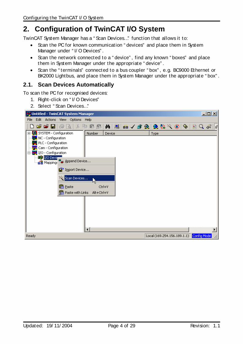
2.1. Scan Devices Automatically To scan the PC for recognised devices:
1. Right-click on “I/O Devices” 2. Select “Scan Devices…”
Configuring the TwinCAT I/O System
Updated: 19/11/2004 Page 5 of 29 Revision: 1.1
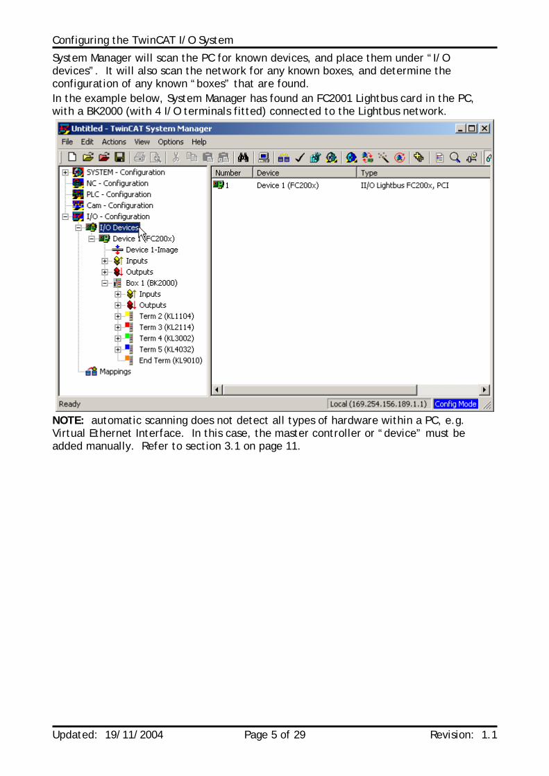
System Manager will scan the PC for known devices, and place them under “I/O devices”. It will also scan the network for any known boxes, and determine the configuration of any known “boxes” that are found. In the example below, System Manager has found an FC2001 Lightbus card in the PC, with a BK2000 (with 4 I/O terminals fitted) connected to the Lightbus network.
NOTE: automatic scanning does not detect all types of hardware within a PC, e.g. Virtual Ethernet Interface. In this case, the master controller or “device” must be added manually. Refer to section 3.1 on page 11.
Configuring the TwinCAT I/O System
Updated: 19/11/2004 Page 6 of 29 Revision: 1.1
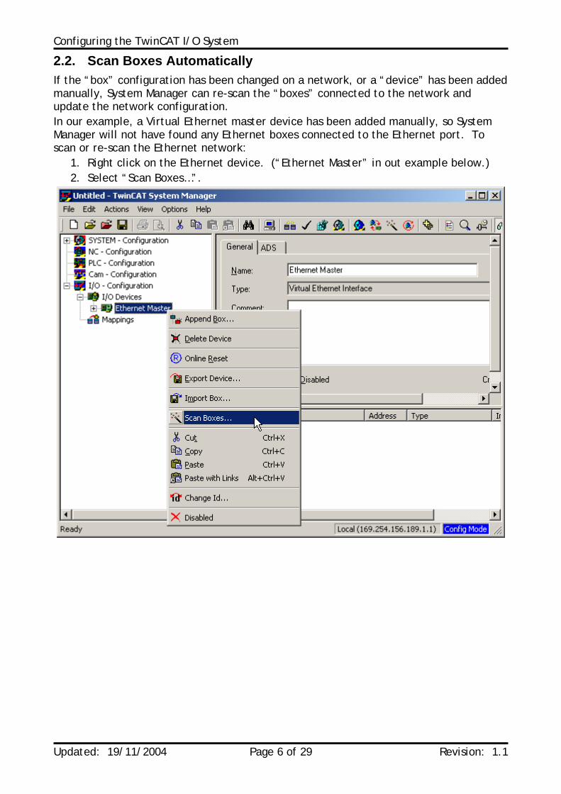
2.2. Scan Boxes Automatically If the “box” configuration has been changed on a network, or a “device” has been added manually, System Manager can re-scan the “boxes” connected to the network and update the network configuration. In our example, a Virtual Ethernet master device has been added manually, so System Manager will not have found any Ethernet boxes connected to the Ethernet port. To scan or re-scan the Ethernet network:
1. Right click on the Ethernet device. (“Ethernet Master” in out example below.) 2. Select “Scan Boxes…”.
Configuring the TwinCAT I/O System
Updated: 19/11/2004 Page 7 of 29 Revision: 1.1
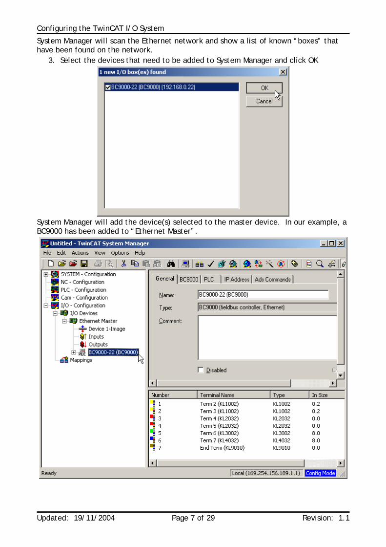
System Manager will scan the Ethernet network and show a list of known “boxes” that have been found on the network.
3. Select the devices that need to be added to System Manager and click OK
System Manager will add the device(s) selected to the master device. In our example, a BC9000 has been added to “Ethernet Master”.
Configuring the TwinCAT I/O System
Updated: 19/11/2004 Page 8 of 29 Revision: 1.1
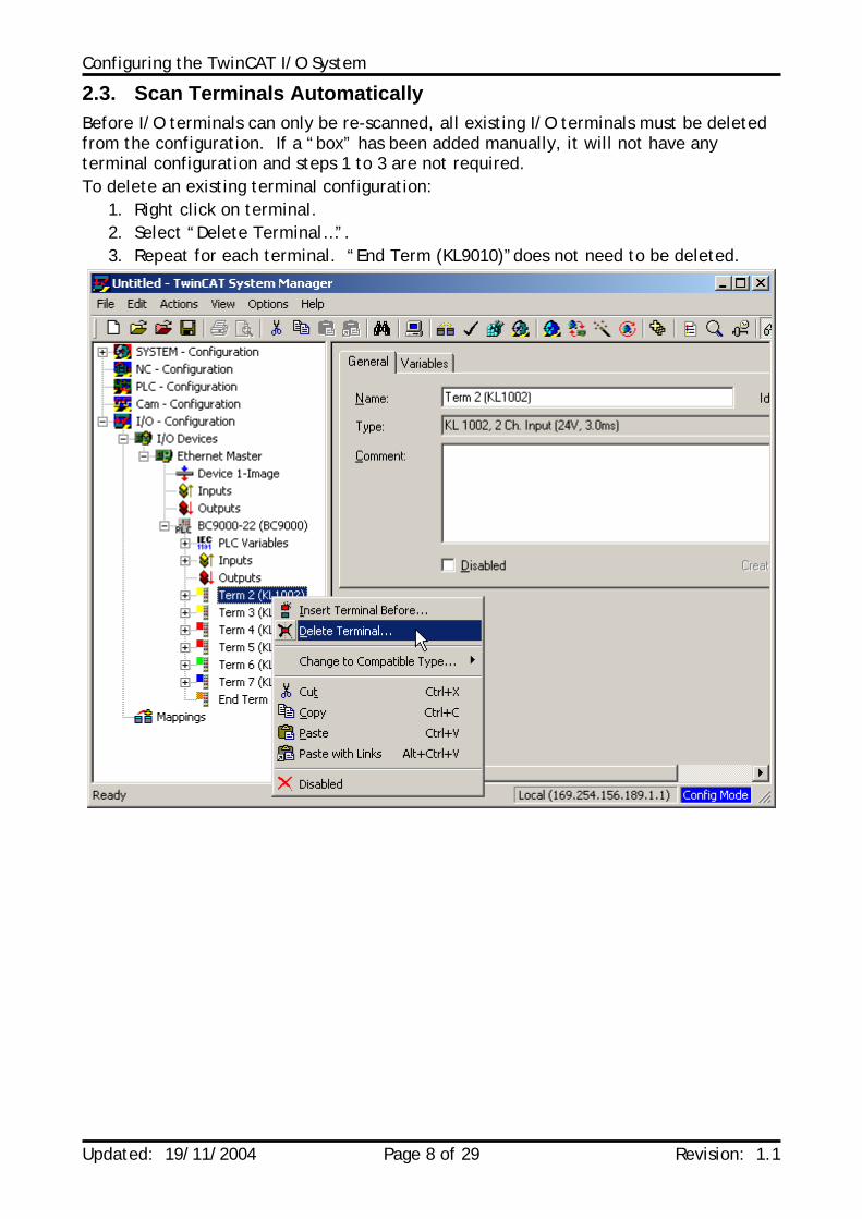
2.3. Scan Terminals Automatically Before I/O terminals can only be re-scanned, all existing I/O terminals must be deleted from the configuration. If a “box” has been added manually, it will not have any terminal configuration and steps 1 to 3 are not required. To delete an existing terminal configuration:
1. Right click on terminal. 2. Select “Delete Terminal…”. 3. Repeat for each terminal. “End Term (KL9010)”does not need to be deleted.
Configuring the TwinCAT I/O System
Updated: 19/11/2004 Page 9 of 29 Revision: 1.1
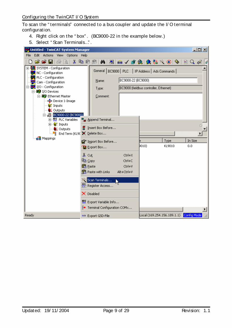
To scan the “terminals” connected to a bus coupler and update the I/O terminal configuration.
4. Right click on the “box”. (BC9000-22 in the example below.) 5. Select “Scan Terminals…”.
Configuring the TwinCAT I/O System
Updated: 19/11/2004 Page 10 of 29 Revision: 1.1
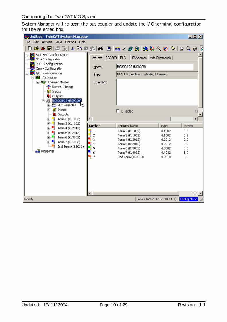
System Manager will re-scan the bus coupler and update the I/O terminal configuration for the selected box.
Configuring the TwinCAT I/O System
Updated: 19/11/2004 Page 11 of 29 Revision: 1.1
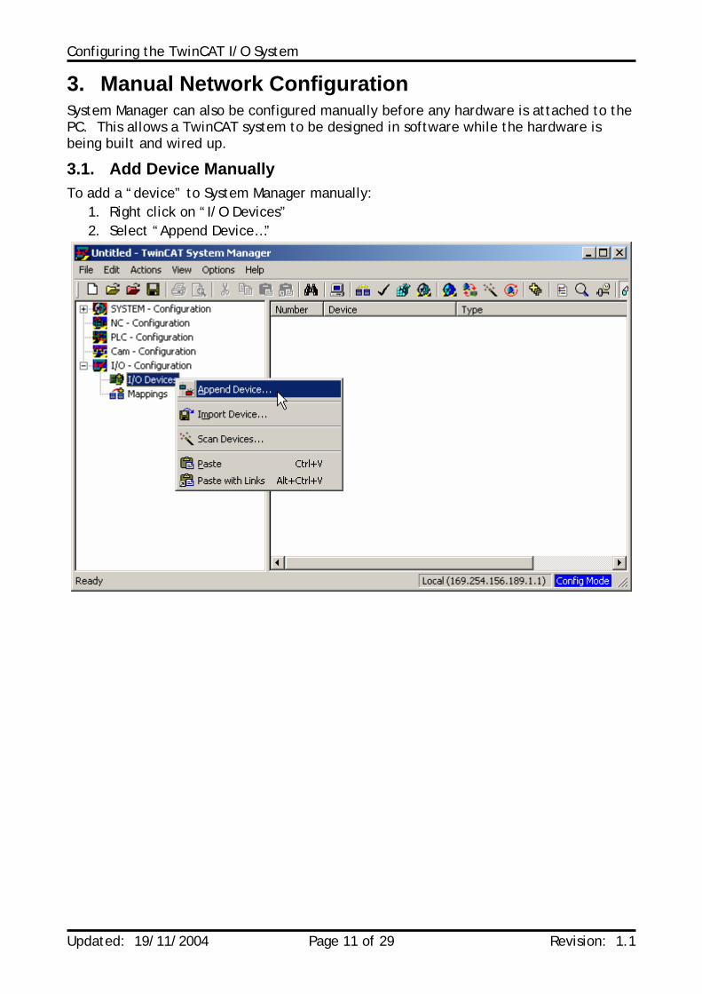
3. Manual Network Configuration System Manager can also be configured manually before any hardware is attached to the PC. This allows a TwinCAT system to be designed in software while the hardware is being built and wired up.
3.1. Add Device Manually To add a “device” to System Manager manually:
1. Right click on “I/O Devices” 2. Select “Append Device…”
Configuring the TwinCAT I/O System
Updated: 19/11/2004 Page 12 of 29 Revision: 1.1
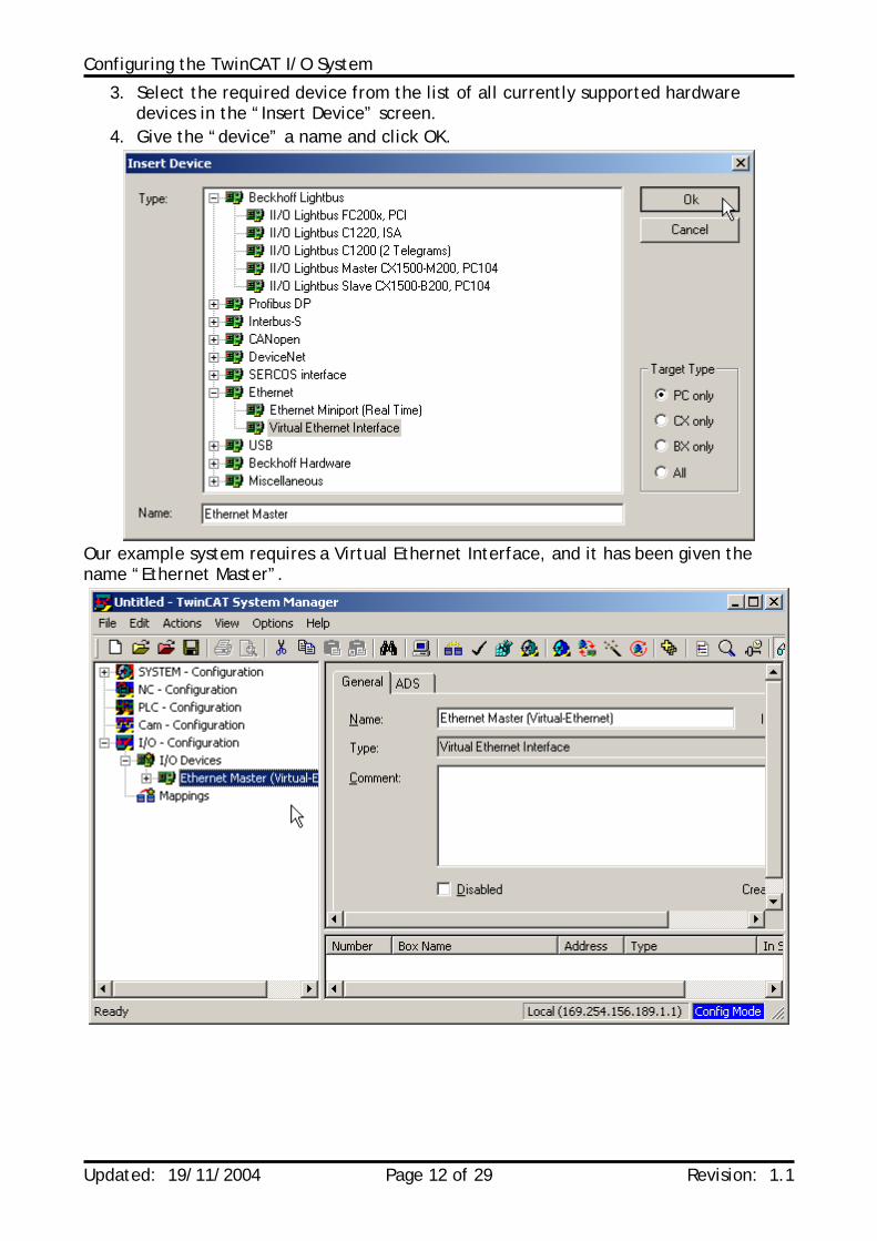
3. Select the required device from the list of all currently supported hardware devices in the “Insert Device” screen.
4. Give the “device” a name and click OK.
Our example system requires a Virtual Ethernet Interface, and it has been given the name “Ethernet Master”.
Configuring the TwinCAT I/O System
Updated: 19/11/2004 Page 13 of 29 Revision: 1.1
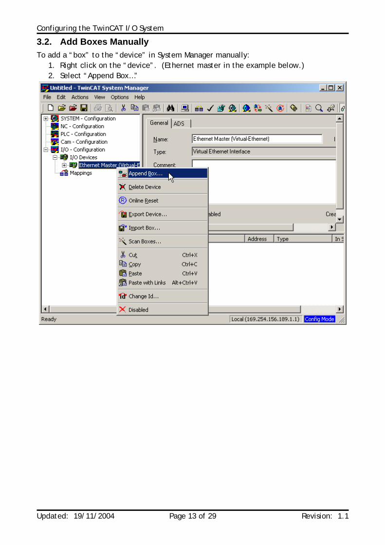
3.2. Add Boxes Manually To add a “box” to the “device” in System Manager manually:
1. Right click on the “device”. (Ethernet master in the example below.) 2. Select “Append Box…”
Configuring the TwinCAT I/O System
Updated: 19/11/2004 Page 14 of 29 Revision: 1.1
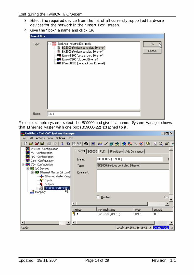
3. Select the required device from the list of all currently supported hardware devices for the network in the “Insert Box” screen.
4. Give the “box” a name and click OK.
For our example system, select the BC9000 and give it a name. System Manager shows that Ethernet Master with one box (BC9000-22) attached to it.
Configuring the TwinCAT I/O System
Updated: 19/11/2004 Page 15 of 29 Revision: 1.1
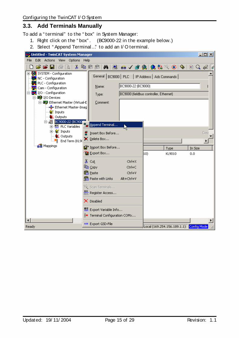
3.3. Add Terminals Manually To add a “terminal” to the “box” in System Manager:
1. Right click on the “box”. (BC9000-22 in the example below.) 2. Select “Append Terminal…” to add an I/O terminal.
Configuring the TwinCAT I/O System
Updated: 19/11/2004 Page 16 of 29 Revision: 1.1
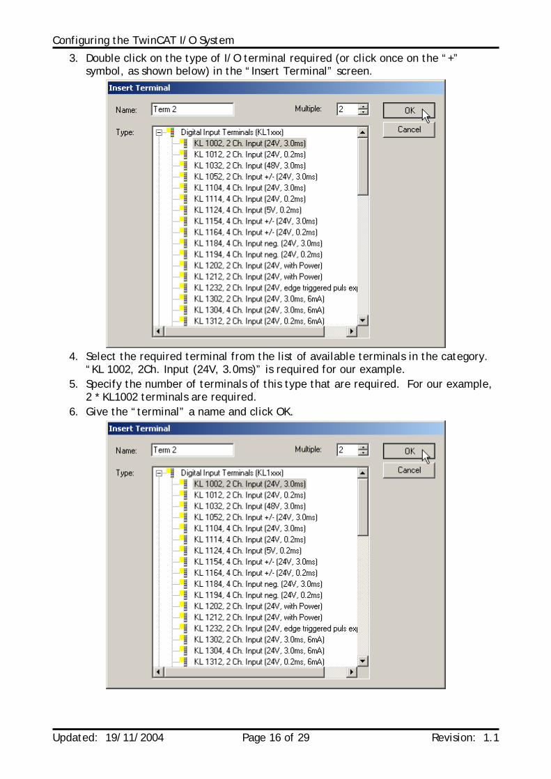
3. Double click on the type of I/O terminal required (or click once on the “+” symbol, as shown below) in the “Insert Terminal” screen.
4. Select the required terminal from the list of available terminals in the category.
“KL 1002, 2Ch. Input (24V, 3.0ms)” is required for our example. 5. Specify the number of terminals of this type that are required. For our example,
2 * KL1002 terminals are required. 6. Give the “terminal” a name and click OK.
Configuring the TwinCAT I/O System
Updated: 19/11/2004 Page 17 of 29 Revision: 1.1
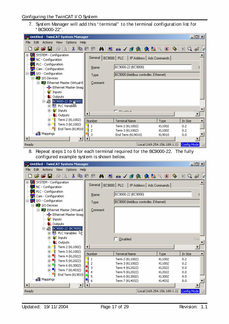
7. System Manager will add this “terminal” to the terminal configuration list for “BC9000-22”.
8. Repeat steps 1 to 6 for each terminal required for the BC9000-22. The fully
configured example system is shown below.

Configuring the TwinCAT I/O System
Updated: 19/11/2004 Page 18 of 29 Revision: 1.1
4. Activate TwinCAT System Configuration When a system configuration has been completed, it should be saved to disk and saved. To activate the new system configuration, 3 steps must be performed:
• Generate mappings • Check configuration • Activate configuration
4.1. Generate Mappings The first step to activating a TwinCAT I/O system configuration is to generate the mappings. This refreshes all links and I/O points within System Manager.
1. Click the Generate Mappings icon ( ) on the TwinCAT System Manager toolbar.
Configuring the TwinCAT I/O System
Updated: 19/11/2004 Page 19 of 29 Revision: 1.1
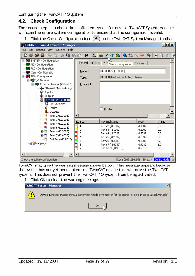
4.2. Check Configuration The second step is to check the configured system for errors. TwinCAT System Manager will scan the entire system configuration to ensure that the configuration is valid.
1. Click the Check Configuration icon ( ) on the TwinCAT System Manager toolbar.
TwinCAT may give the warning message shown below. This message appears because the system has not yet been linked to a TwinCAT device that will drive the TwinCAT system. This does not prevent the TwinCAT I/O system from being activated.
1. Click OK to clear the warning message.
Configuring the TwinCAT I/O System
Updated: 19/11/2004 Page 20 of 29 Revision: 1.1
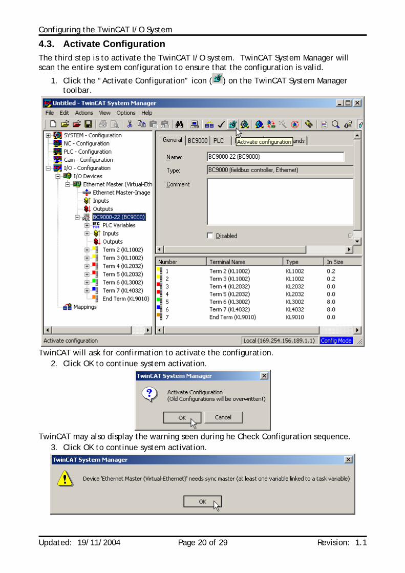
4.3. Activate Configuration The third step is to activate the TwinCAT I/O system. TwinCAT System Manager will scan the entire system configuration to ensure that the configuration is valid.
1. Click the “Activate Configuration” icon ( ) on the TwinCAT System Manager toolbar.
TwinCAT will ask for confirmation to activate the configuration.
2. Click OK to continue system activation.
TwinCAT may also display the warning seen during he Check Configuration sequence.
3. Click OK to continue system activation.
Configuring the TwinCAT I/O System
Updated: 19/11/2004 Page 21 of 29 Revision: 1.1
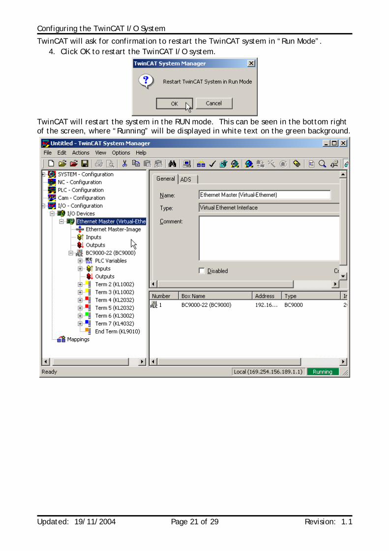
TwinCAT will ask for confirmation to restart the TwinCAT system in “Run Mode”. 4. Click OK to restart the TwinCAT I/O system.
TwinCAT will restart the system in the RUN mode. This can be seen in the bottom right of the screen, where “Running” will be displayed in white text on the green background.
Configuring the TwinCAT I/O System
Updated: 19/11/2004 Page 22 of 29 Revision: 1.1
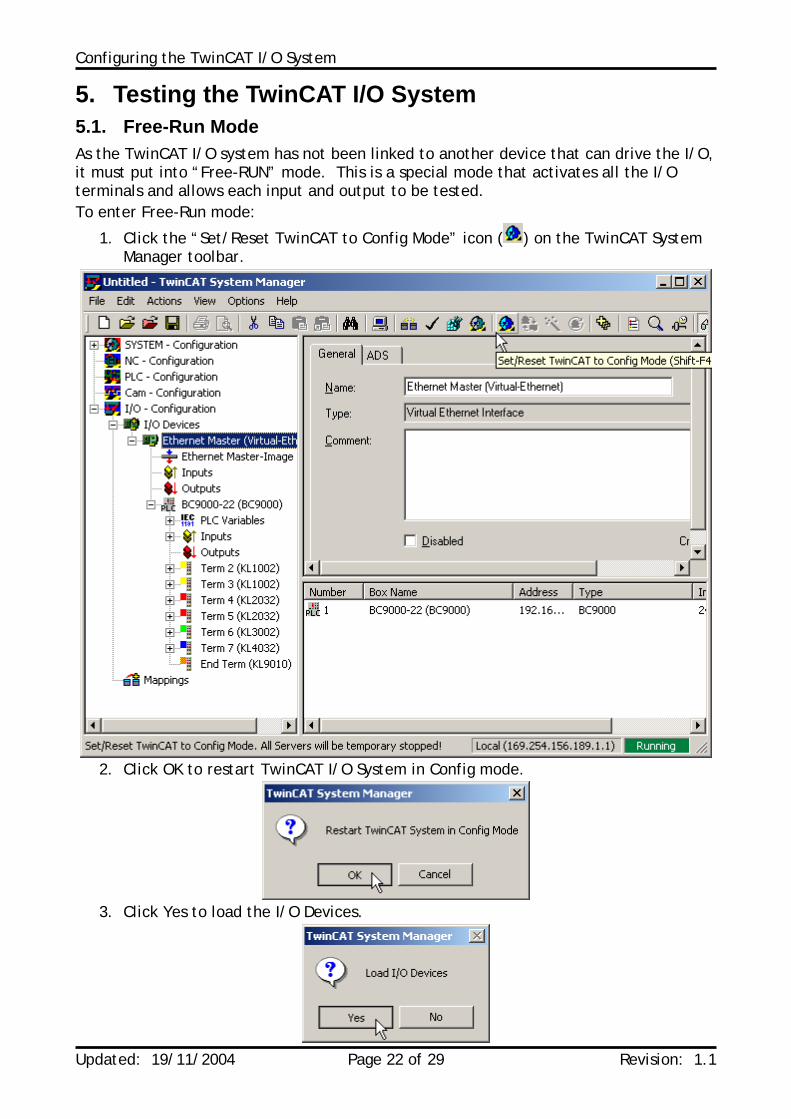
5. Testing the TwinCAT I/O System 5.1. Free-Run Mode As the TwinCAT I/O system has not been linked to another device that can drive the I/O, it must put into “Free-RUN” mode. This is a special mode that activates all the I/O terminals and allows each input and output to be tested. To enter Free-Run mode:
1. Click the “Set/Reset TwinCAT to Config Mode” icon ( ) on the TwinCAT System Manager toolbar.
2. Click OK to restart TwinCAT I/O System in Config mode.
3. Click Yes to load the I/O Devices.
Configuring the TwinCAT I/O System
Updated: 19/11/2004 Page 23 of 29 Revision: 1.1
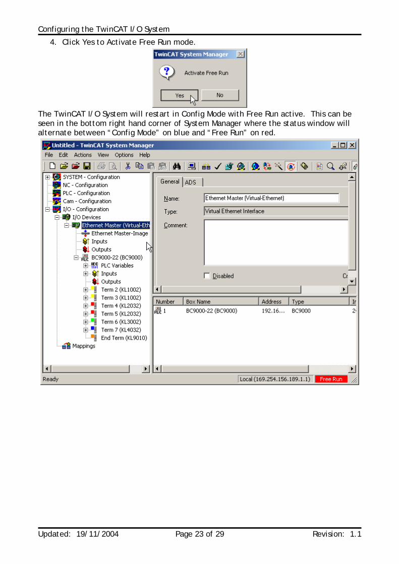
4. Click Yes to Activate Free Run mode.
The TwinCAT I/O System will restart in Config Mode with Free Run active. This can be seen in the bottom right hand corner of System Manager where the status window will alternate between “Config Mode” on blue and “Free Run” on red.
Configuring the TwinCAT I/O System
Updated: 19/11/2004 Page 24 of 29 Revision: 1.1
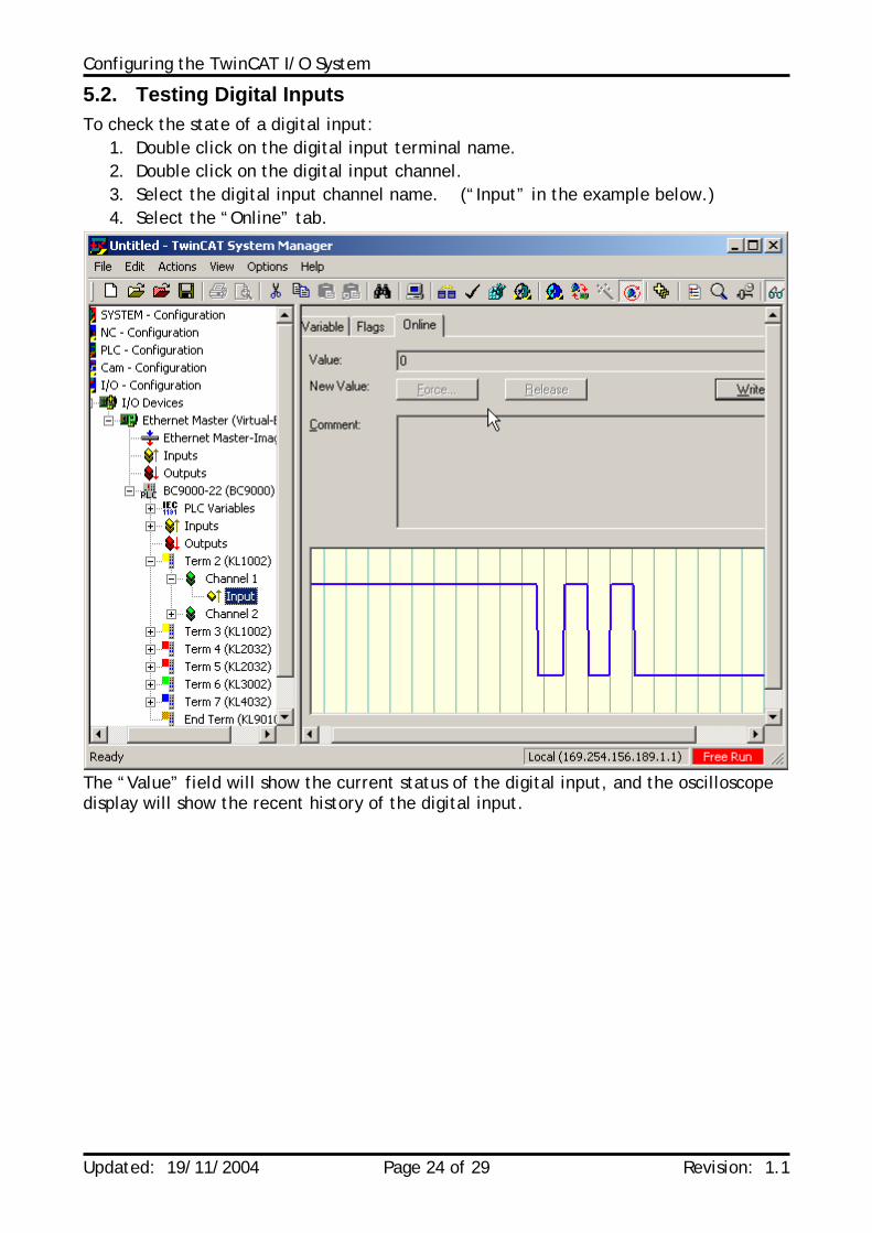
5.2. Testing Digital Inputs To check the state of a digital input:
1. Double click on the digital input terminal name. 2. Double click on the digital input channel. 3. Select the digital input channel name. (“Input” in the example below.) 4. Select the “Online” tab.
The “Value” field will show the current status of the digital input, and the oscilloscope display will show the recent history of the digital input.
Configuring the TwinCAT I/O System
Updated: 19/11/2004 Page 25 of 29 Revision: 1.1
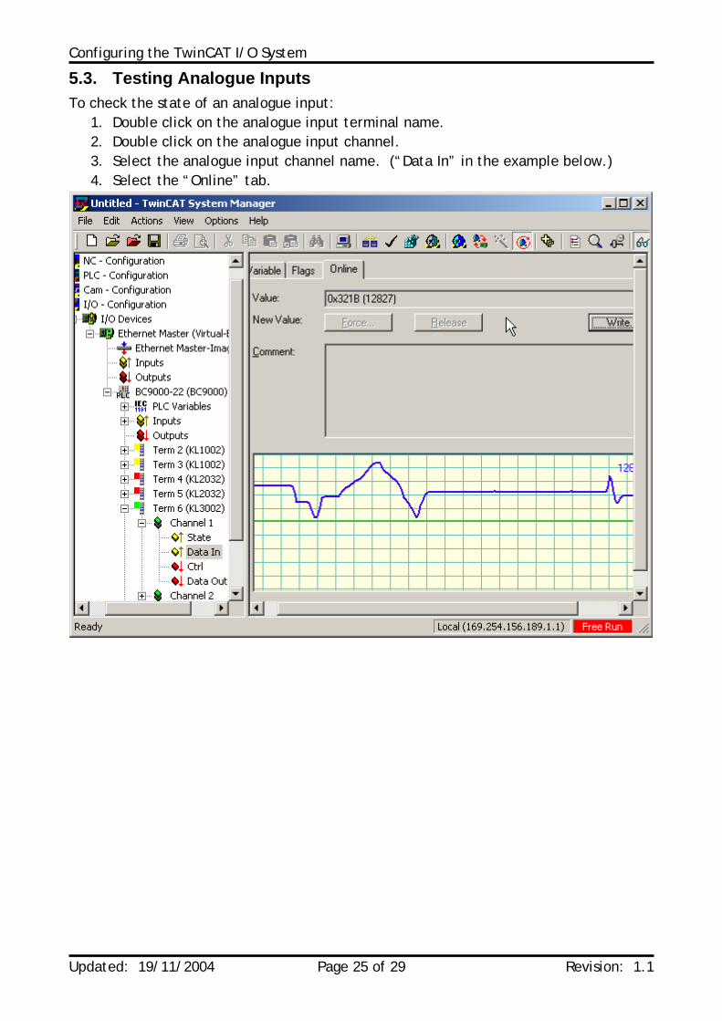
5.3. Testing Analogue Inputs To check the state of an analogue input:
1. Double click on the analogue input terminal name. 2. Double click on the analogue input channel. 3. Select the analogue input channel name. (“Data In” in the example below.) 4. Select the “Online” tab.
Configuring the TwinCAT I/O System
Updated: 19/11/2004 Page 26 of 29 Revision: 1.1
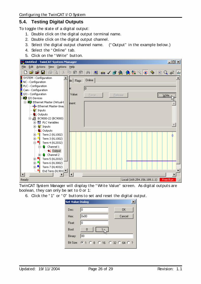
5.4. Testing Digital Outputs To toggle the state of a digital output:
1. Double click on the digital output terminal name. 2. Double click on the digital output channel. 3. Select the digital output channel name. (“Output” in the example below.) 4. Select the “Online” tab. 5. Click on the “Write” button.
TwinCAT System Manager will display the “Write Value” screen. As digital outputs are boolean, they can only be set to 0 or 1:
6. Click the “1” or “0” buttons to set and reset the digital output.
Configuring the TwinCAT I/O System
Updated: 19/11/2004 Page 27 of 29 Revision: 1.1
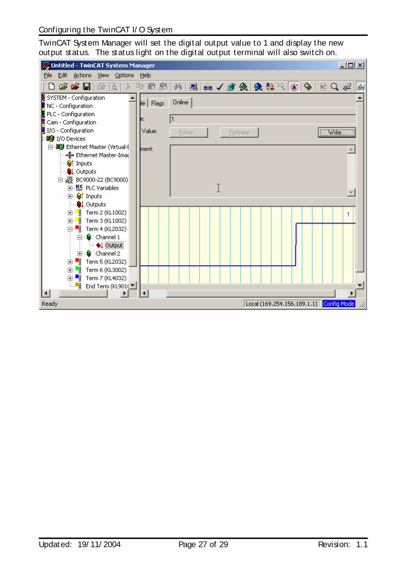
TwinCAT System Manager will set the digital output value to 1 and display the new output status. The status light on the digital output terminal will also switch on.
Configuring the TwinCAT I/O System
Updated: 19/11/2004 Page 28 of 29 Revision: 1.1
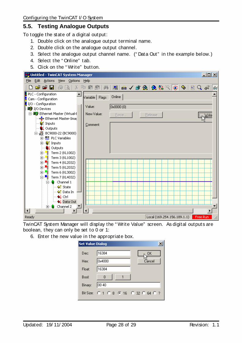
5.5. Testing Analogue Outputs To toggle the state of a digital output:
1. Double click on the analogue output terminal name. 2. Double click on the analogue output channel. 3. Select the analogue output channel name. (“Data Out” in the example below.) 4. Select the “Online” tab. 5. Click on the “Write” button.
TwinCAT System Manager will display the “Write Value” screen. As digital outputs are boolean, they can only be set to 0 or 1:
6. Enter the new value in the appropriate box.
Configuring the TwinCAT I/O System
Updated: 19/11/2004 Page 29 of 29 Revision: 1.1
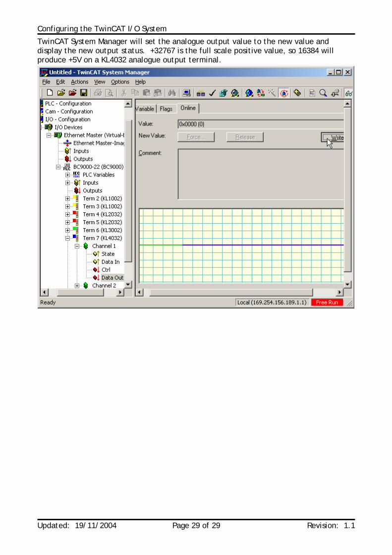
TwinCAT System Manager will set the analogue output value to the new value and display the new output status. +32767 is the full scale positive value, so 16384 will produce +5V on a KL4032 analogue output terminal.