Conference paper final - Department of ECE
8
Smart Cabinets Brenden Apwisch, Jacob Davis, Jacob Hernandez, Mohammad Hammad Dept. of Electrical and Computer Engineering University of Central Florida, Orlando, Florida, 32816-2450 Abstract — The goal of this project is to create smart cabinet model which features convenient security for it’s users. In order to do so our product features mobile access control, app interfaces, item tracking, and also remote function capabilities. Together these features will allow a user to seamlessly access their protected items without the worry of any unauthorized persons doing the same. Our project is sponsored by UniKey which is a leader in the mobile access control industry. In order to prove the usability of UniKey’s platform while also creating a product which we can foresee being in used in the future of smart homes, we decided to create our product called Smart Cabinets. Index Terms — BLE, capacitive touch, electromagnetic home automation, lock, mobile phone app, remote access control, security, smart cabinet I. INTRODUCTION With the rapid growth of smart homes and use of technology for every day functions in mind, our group decided to design a product which can set the tone for convenient security within the home. What we mean by “convenient security” is that a user should not have to find keys or wait to access their belongings within their own home. However, that does not mean they don’t desire to secure some items from guests, routine house workers, or even their children; therefore we set out to develop a product which will allow them to have security from others but seamless but also convenient access for themselves and other authorized users. Since our project is sponsored by UniKey we used their mobile access control platform to ensure our product features a trusted and robust security protocol. In doing so we were free to focus more on the overall functionality of our product and the mobile application which controls it, while they gave us the tools needed to handle all electronic key (e-key) transactions over Bluetooth Low Energy (BLE) communication. While the prototype of Smart Cabinet product is only demonstrated on a standard kitchen cabinet, it’s uses are intended to be applicable to any type of storage in the home which could require security. Specifically, we see our product being used for medicine cabinets, pantries, liquor cabinets, and home office set ups. Whether the goal is keeping children away from medicines, cleaning supplies, etc. or even protecting important office work, our goal is for our Smart Cabinet design to be the quintessence of convenient security within the home. II. SYSTEM HARDWARE The project is best represented as a collection of smaller parts, whether purchased or designed, that are interfaced together to create the final product. A. Cabinet The cabinet that was chosen for the project needed to fit the model of the cabinet in figure 1. The group wanted there to be at least 1 shelf inside the cabinet for storage and for there to be only 1 door that swings open rather than pulling and pushing closed. This is the most common cabinet design we found and wanted to design our product for common use. Fig 1. An example of a cabinet that fit the group’s design. B. Printed Circuit Board – Coprocessor and Host The Printed Circuit Board (PCB) is a hub for every major component within the cabinet and a model is shown in figure 2. The PCB has two major components in it that control most of the work for our system, the host and coprocessor. The host is an Atmega328-PU and the coprocessor is the MKW31Z512. The host works as our hardware controller, communicating with the coprocessor through serial lines. As an analogy, the coprocessor is the brain that does all the instructing and the host is the muscles that move all the extremities.
Transcript of Conference paper final - Department of ECE

Smart Cabinets Brenden Apwisch, Jacob Davis, Jacob
Hernandez, Mohammad Hammad Dept. of Electrical and Computer Engineering
University of Central Florida, Orlando, Florida, 32816-2450
Abstract — The goal of this project is to create smart cabinet model which features convenient security for it’s users. In order to do so our product features mobile access control, app interfaces, item tracking, and also remote function capabilities. Together these features will allow a user to seamlessly access their protected items without the worry of any unauthorized persons doing the same. Our project is sponsored by UniKey which is a leader in the mobile access control industry. In order to prove the usability of UniKey’s platform while also creating a product which we can foresee being in used in the future of smart homes, we decided to create our product called Smart Cabinets.
Index Terms — BLE, capacitive touch, electromagnetic home automation, lock, mobile phone app, remote access control, security, smart cabinet
I. INTRODUCTION
With the rapid growth of smart homes and use of technology for every day functions in mind, our group decided to design a product which can set the tone for convenient security within the home. What we mean by “convenient security” is that a user should not have to find keys or wait to access their belongings within their own home. However, that does not mean they don’t desire to secure some items from guests, routine house workers, or even their children; therefore we set out to develop a product which will allow them to have security from others but seamless but also convenient access for themselves and other authorized users. Since our project is sponsored by UniKey we used their mobile access control platform to ensure our product features a trusted and robust security protocol. In doing so we were free to focus more on the overall functionality of our product and the mobile application which controls it, while they gave us the tools needed to handle all electronic key (e-key) transactions over Bluetooth Low Energy (BLE) communication. While the prototype of Smart Cabinet product is only demonstrated on a standard kitchen cabinet, it’s uses are intended to be applicable to any type of storage in the home which could require security. Specifically, we see our product being used for medicine cabinets, pantries, liquor cabinets, and home office set ups. Whether the goal is keeping children away from
medicines, cleaning supplies, etc. or even protecting important office work, our goal is for our Smart Cabinet design to be the quintessence of convenient security within the home.
II. SYSTEM HARDWARE
The project is best represented as a collection of smaller parts, whether purchased or designed, that are interfaced together to create the final product.
A. Cabinet The cabinet that was chosen for the project needed to fit
the model of the cabinet in figure 1. The group wanted there to be at least 1 shelf inside the cabinet for storage and for there to be only 1 door that swings open rather than pulling and pushing closed. This is the most common cabinet design we found and wanted to design our product for common use.
Fig 1. An example of a cabinet that fit the group’s
design. B. Printed Circuit Board – Coprocessor and Host
The Printed Circuit Board (PCB) is a hub for every
major component within the cabinet and a model is shown in figure 2. The PCB has two major components in it that control most of the work for our system, the host and coprocessor. The host is an Atmega328-PU and the coprocessor is the MKW31Z512. The host works as our hardware controller, communicating with the coprocessor through serial lines. As an analogy, the coprocessor is the brain that does all the instructing and the host is the muscles that move all the extremities.

Fig. 2. A model of the CHU.
C. Coprocessor NXP’s MKW31Z512 is chosen as the coprocessor for
this project because of some key features it has relative to competitors. Not only does it meet the standards we are required to meet by UniKey, it is also the only coprocessor we found that has all the capabilities that we are looking for. The main selling points for this coprocessor are: programmable interrupt timer for capsense functions, true random number generator for security functions, low power mode, serial communication, and Bluetooth-LE v4.2 capability. It has 512 KB of flash memory and 26 GPIO pins. One downside is that there is not a built in BLE antenna, so an external one must be used. Another consideration to be made was the fact the MKW runs at 3.3V logic and the host runs at 5V, thus it must be level shifted to communicate with the host without damaging either processors.
D. BLE Antenna Due to the choice of coprocessor, an external BLE
antenna is required. With guidance from UniKey, one was built from scratch rather than buying one. This was done with a copper plate and wire, which then plugs into the PCB, and is routed to the coprocessor to amplify the BLE signal and is as shown in figure 3.
Fig. 3. The BLE antenna.
E. Host The Atmega328-PU is our hardware controller and is a
perfect suite due to its 23 GPIO pins, 32KB of flash memory and compatibility with UART/USART. There is also a lot of support for this hardware found online and it can be easily be programmed using an Arduino, thus making it a no brainer for our hardware controller. The host needs to have UART or SPI interfaces in order to communicate with the coprocessor. The host runs at logic level of 5V thus it must be level shifted to 3.3V in order to communicate with the coprocessor, to avoid damaging the processors.
E. Locking Mechanism The AGPtek 60kg Holding Force Electric Magnetic
Lock is used to keep the cabinet door locked unless a user is accessing the cabinet. The lock requires a constant supply of 12V in order to operate. Turning the lock off is done by switching a relay on the PCB. The relay is switches by applying a 5V signal to it.
F. Servo The project is designed to open and close automatically
and is done so by using an MG995 servo. The servo requires 4.8V in order to function and is able to supply a torque of 9.4 kg*cm. The servo is connected to an arm that will rotate a crank that will rotate the door. An example of this process is shown in figure 4.
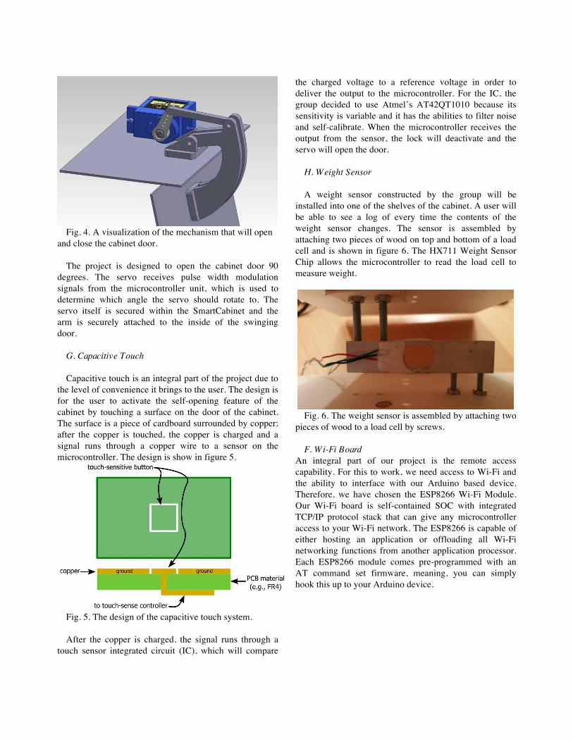
Fig. 4. A visualization of the mechanism that will open
and close the cabinet door. The project is designed to open the cabinet door 90
degrees. The servo receives pulse width modulation signals from the microcontroller unit, which is used to determine which angle the servo should rotate to. The servo itself is secured within the SmartCabinet and the arm is securely attached to the inside of the swinging door.
G. Capacitive Touch Capacitive touch is an integral part of the project due to
the level of convenience it brings to the user. The design is for the user to activate the self-opening feature of the cabinet by touching a surface on the door of the cabinet. The surface is a piece of cardboard surrounded by copper; after the copper is touched, the copper is charged and a signal runs through a copper wire to a sensor on the microcontroller. The design is show in figure 5.
Fig. 5. The design of the capacitive touch system. After the copper is charged, the signal runs through a
touch sensor integrated circuit (IC), which will compare
the charged voltage to a reference voltage in order to deliver the output to the microcontroller. For the IC, the group decided to use Atmel’s AT42QT1010 because its sensitivity is variable and it has the abilities to filter noise and self-calibrate. When the microcontroller receives the output from the sensor, the lock will deactivate and the servo will open the door.
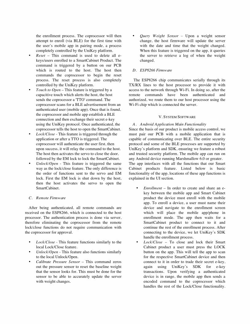
H. W eight Sensor A weight sensor constructed by the group will be
installed into one of the shelves of the cabinet. A user will be able to see a log of every time the contents of the weight sensor changes. The sensor is assembled by attaching two pieces of wood on top and bottom of a load cell and is shown in figure 6. The HX711 Weight Sensor Chip allows the microcontroller to read the load cell to measure weight.
Fig. 6. The weight sensor is assembled by attaching two
pieces of wood to a load cell by screws. F. W i-Fi Board
An integral part of our project is the remote access capability. For this to work, we need access to Wi-Fi and the ability to interface with our Arduino based device. Therefore, we have chosen the ESP8266 Wi-Fi Module. Our Wi-Fi board is self-contained SOC with integrated TCP/IP protocol stack that can give any microcontroller access to your Wi-Fi network. The ESP8266 is capable of either hosting an application or offloading all Wi-Fi networking functions from another application processor. Each ESP8266 module comes pre-programmed with an AT command set firmware, meaning, you can simply hook this up to your Arduino device.

III. POWER SYSTEM
The power will be supplied from a standard USA and
Canada wall outlet. Our power converter (Berls BS-24W1202000W) converts the 125V AC and 15A produced by the wall outlet into 12V DC and 3A.
A. Power Routing
All the major hardware components require one of three voltage levels to run: 3.3V, 5V, or 12V. The different levels are achieved through two voltage regulators that drop the voltage lines to our needed values. The power schematic can be seen in Figure 7. The two regulators, 3.3V and 5V, we have on the PCB are limited to a 1.2A current draw, which is enough current to power our on-board components. Our two highest current draws are from the servo and the EM lock. They are routed through the 12V line which is not current restricted by the regulators. The servo is routed through a separate regulator that is off of the main 12V power trace as it requires 5V to operate. Our main component consumption and requirements are listed in Table I. We supply the PCB with up to 3A in the case of a current spike from any components.
TABLE I
Component Voltage Requirements
Component Voltage Required
Current Required
Power Consumption
MKW31Z512 3.3V ~200mA 660mW
AT42QT1010 3.3V 1mA 3.3mW
MG995 5V 500mA 2.5W
HX711 5V 2mA 10mW
Atmega328 5V 200mA 1W
AGPtek Lock 12V 150mA 1.8W
Fig. 7. Representation of the two regulator power system.
IV. SYSTEM FIRMWARE
A. Firmware Overview
The firmware is implemented on a MKW31Z512 and a Atmega328-PU, referred to as the coprocessor and the host respectively. The coprocessor handles all BLE communications and security processes. The host controls all hardware and peripherals that the user will mostly interface with. The two processors communicate with each other through UART serial communication and together control the entire SmartCabinet. The UART serial communication is the only connection between the two processors. The general process between the coprocessor and the host begins when the user desires to operate the cabinet, through the app or through hardware interface. At the start of any event, the command is authenticated to determine if the user is authorized, and then continues to perform the desired function. User commands can be either transmitted/received locally or remotely, slightly altering our process. Local commands are authenticated by the communication between the coprocessor and the mobile app using UniKey’s security protocol, seen in figure 8. The main local commands are touch to open (TTO), enrollment, reset, lock/close, and unlock/open. The main remote access commands are authenticated through the communication between the mobile app and the server endpoint. The remote commands only include lock/close, unlock/open, and query weight sensor.
Fig. 8. UniKey’s Security Protocol
B. Local Firmware
• Enrollment - This command is used when enrolling a new user to a SmartCabinet product and granting the user an e-key which gives access to the SmartCabinet functions. Enrollment is triggered by a button on our PCB which is routed to the host. The host then commands the coprocessor to begin
the enrollment process. The coprocessor will then attempt to enroll (via BLE) for the first time with the user’s mobile app in pairing mode, a process completely controlled by the UniKey platform.
• Reset – This command is used to delete all e-keys/users enrolled to a SmartCabinet Product. The command is triggered by a button on our PCB which is routed to the host. The host then commands the coprocessor to begin the reset process. The reset process is also completely controlled by the UniKey platform.
• Touch to Open – This feature is triggered by a capacitive touch which alerts the host, the host sends the coprocessor a 'TTO' command. The coprocessor scans for a BLE advertisement from an authenticated user (mobile app). Once that is found, the coprocessor and mobile app establish a BLE connection and then exchange their secret e-key using the UniKey protocol. Once authenticated, the coprocessor tells the host to open the SmartCabinet.
• Lock/Close - This feature is triggered through the application or after a TTO is triggered. The coprocessor will authenticate the user first, then upon success, it will relay the command to the host. The host then activates the servo to close the door, followed by the EM lock to lock the SmartCabinet.
• Unlock/Open - This feature is triggered the same way as the lock/close feature. The only difference is the order of functions sent to the servo and EM lock. First the EM lock is shut down by the host, then the host activates the servo to open the SmartCabinet.
C. Remote Firmware
After being authenticated, all remote commands are
received on the ESP8266, which is connected to the host processor. The authentication process is done via server, therefore eliminating the coprocessor from the remote lock/close functions do not require communication with the coprocessor for approval.
• Lock/Close - This feature functions similarly to the
local Lock/Close feature. • Unlock/Open - This feature also functions similarly
to the local Unlock/Open. • Calibrate Pressure Sensor – This command zeros
out the pressure sensor to reset the baseline weight that the sensor looks for. This must be done for the sensor to be able to accurately update the server with weight changes.
• Query W eight Sensor – Upon a weight sensor change, the host firmware will update the server with the date and time that the weight changed. When this feature is triggered on the app, it queries the server to retrieve a log of when the weight changed.
D. ESP8266 Firmware
The ESP8266 chip communicates serially through its TX/RX lines to the host processor to provide it with access to the network through Wi-Fi. In doing so, after the remote commands have been authenticated and authorized, we route them to our host processor using the Wi-Fi chip which is connected the server.
V. SYSTEM SOFTWARE
A. Android Application Main Functionality Since the basis of our product is mobile access control, we must pair our PCB with a mobile application that is capable of communicating over BLE. The entire security protocol and some of the BLE processes are supported by UniKey’s platform and SDK, ensuring we feature a robust and trusted security platform. The mobile app can run on any Android device running Marshmallow 6.0 or greater. The app interfaces with all the functions that our Smart Cabinet products feature. Listed below is basic functionality of the app, locations of these app functions is explained in the UI section.
• Enrollment – In order to create and share an e-key between the mobile app and Smart Cabinet product the device must enroll with the mobile app. To enroll a device, a user must name their device and navigate to the enrollment screen which will place the mobile app/phone in enrollment mode. The app then waits for a SmartCabinet product to connect to it and continue the rest of the enrollment process. After connecting to the device, we let UniKey’s SDK handle the enrollment process.
• Lock/Close – To close and lock their Smart Cabinet product a user must press the LOCK button on the app. This will tell the app to scan for the respective SmartCabinet device and then connect to it in order to trade their secret e-key, again using UniKey’s SDK for e-key transactions. Upon verifying a authenticated device is in range, the mobile app then sends a encoded command to the coprocessor which handles the rest of the Lock/Close functionality.

The app waits for a confirmation of the lock/close with a lock status and then updates the app UI respectively.
• Unlock/Open - To unlock and open their Smart Cabinet product a user must press the UNLOCK button on the app. This will tell the app to scan for the respective SmartCabinet device and then connect to it in order to trade their secret e-key, again using UniKey’s SDK for e-key transactions. Upon verifying a authenticated device is in range, the mobile app then sends a encoded command to the coprocessor which handles the rest of the Unlock/Open functionality. The app waits for a confirmation of the lock/close with a lock status and then updates the app UI respectively.
• Touch to Open – The TTO or touch to open functionality of the app works a little differently than the other functions. Mainly because it does not have a user interface trigger/button and is initialized through a hardware interface. Upon a TTO signal, the coprocessor attempts to connect and pair with the mobile app. In order for this functionality to work seamlessly, the mobile app is constantly advertising its presence over BLE. The coprocessor scans this advertisement and connects to the app after trading the secret e-key, again using UniKey’s platform/SDK for e-key transactions. After that process the mobile app continues it the TTO process by retrieving the current lock state from the coprocessor, which in turn retrieves from the host. After receiving the current lock state, the mobile app toggles the lock state by sending the coprocessor a lock/close or unlock/open command respectively.
• Query W eight Sensor – The query weight sensor function is triggered by the user pressing the QUERY WEIGHT SENSOR button. This command is intended to be used remotely, so the app does not attempt to scan for a nearby SmartCabinet product. Instead it pings our secure server using its credentials to retrieve a log of movements recorded by our Weight Sensor System.
• Calibrate Sensor – This function is triggered by pressing the CALIBRATE WEIGHT SENSOR button and it commands the coprocessor to direct the host to recalibrate the weight sensor system. The system expects the desired object to be tracked to be placed on the weight sensor prior to pressing this button. Upon completion of this
function the Smart Cabinet device’s “smart shelf” is now tracking and logging a new item/weight.
Since we intended for our Smart Cabinet product to have the ability to be controlled remotely, we must add remote functionality to our app as well. Using the combinations of UniKey’s credentials and a secure server we implemented our remote functionalities. They can include:
• Lock/Close – Operates the same as a local
Lock/Close feature but is authenticated using UniKey credentials on a server which is connected to our host via the ESP8266.
• Unlock/Open - Operates the same as a local Unlock/Open feature but is authenticated using UniKey credentials on a server which is connected to our host via the ESP8266.
The TTO and Calibrate Weight Sensors are only intended to work locally, therefore will not operate in remote conditions.
B. Server Functionality In order to allow the ability to remotely control the cabinet, the PCB is connected to a server through Wi-Fi by utilizing the Wi-Fi board. Whenever a remote command is triggered via the mobile application, the phone connects to our secure server. It then authenticates and authorizes the command if it was transmitted by a user with a valid e-key that is shared with the SmartCabinet product. The remote security protocol is processed using the e-key which is tied to a user’s app account credentials. Storing and validating e-keys is done via UniKey’s platform, thus the main software implementation was for connecting our mobile app and SmartCabinet to the same server endpoints. Upon completing the UniKey security protocol our server relays all remote commands from the mobile app directly to our host processor, which will finish the command and update the mobile app respectively.
VI. USER INTERFACE
A. Login Screen
An important aspect to the SmartCabinet design is the simplicity of the user interface within the mobile app. As shown in figure 9, the login screen features fields for entering the user’s email address and password. Due to the group’s sponsorship from UniKey, they provide the login

credentials used for login. The username and password are the same credentials used for the user’s UniKey account.
Fig. 9. Screenshot of the login screen.
B. Key List
After logging into their account, a user will be brought to the Key List. The Key List shows all of the SmartCabinet devices that a user is registered with. As an example, figure 10 shows a sample Key List with “Loomis Home” listed as a registered device. The user sets the name of the device before they enroll the application with the cabinet. The page also includes the Logout and Enroll buttons on the top-right of the screen. Logout takes you back to the login screen. The enroll button begins the enrollment process for another SmartCabinet product.
Fig. 10. Screenshot of the Key List.
C. Device Dashboard
On the Device Dashboard, there are 7 different buttons that a user can trigger as shown in figure 11. On the top of the screen, a user can select to lock or unlock the cabinet. The lock button also closes the cabinet door and the unlock button opens the cabinet door. In addition, there is a button to switch between “local” and “remote” mode in order to control the SmartCabinet from within BLE range and when not within that range. There is a calibration button that allows the user to reset the weight sensor to track a specific weight. The user can select to query the weight sensor using the button “Query Weight Sensor” and the weight change log is presented in the white window. Selecting the “Device History” button brings up a separate window with a more expansive history of readings from the weight sensor. Above the log, the user can see the current state of the cabinet (either locked or unlocked) and this state is updated whenever the user has the mobile app open and can change the state of the cabinet by the push of a button or by the capacitive touch, if within BLE pairing range. In the top-left of the screen, the user can click the arrow to return to the Key List.
Fig. 11. Screenshot of the Device Dashboard.
VII. CONCLUSION
All of the aforementioned systems are in place to realize the SmartCabinet vision. All the systems were tested to work in conjuncture with the UniKey platform, which promises security, seamlessness, and reliability. From this undertaking much has been learned which helped us move forward and learn to work as a team as well as discovering new technologies and methods for accomplishing a task or

solving a problem. There is always room for improvement and a newer, more robust version of any product can always be made. For the second iteration, there are always improvements to be made and there are many different solutions to solve a real problem. That being said, many options were tested and through our experience we were able to learn to implement a better project for the future and a modern household security system.
ACKNOWLEDGEMENT
The authors wish to thank the assistance and support of UniKey and the University of Central Florida whom this project would not have been possible without.
REFERENCES
[1] UniKey: https://www.unikey.com/ [2] MKW41Z512: https://www.nxp.com/docs/en/data-sheet/MKW41Z512.pdf [3] ATmega328: http://ww1.microchip.com/downloads/en/DeviceDoc/Atmel-42735-8-bit-AVR-Microcontroller-ATmega328-328P_Datasheet.pdf [4] BLE Specifications: https://www.bluetooth.com/specifications/bluetooth-core-specification [5] HX711 Weight Sensor: https://cdn.sparkfun.com/datasheets/Sensors/ForceFlex/hx711_english.pdf
AUTHORS
Brenden Apwisch is a senior enrolled in the University of Central Florida's Computer Engineering program. He plans to graduate with his Bachelors in May 2018 and move directly into industry. He has a passion for both front-end and back-end software engineering, which allows him to see the whole picture of his works. He plans
to start a career in full-stack development including both mobile application and server development.
Jacob Davis is graduating in the Spring 2018 semester as a Provost Scholar. He is receiving his Bachelor’s Degree in Electrical Engineering. During his time as UCF, he worked as a Team Leader for the Honors College
and found a passion producing podcasts and other media. He has taken a full-time position as a Content Marketing Specialist with Empire Flippers.
Jacob Hernandez is receiving his Bachelor’s Degree in Electrical Engineering from the University of Central Florida. He has a job lined up at Lockheed Martin Missile and Fire Control as a Systems Engineer. While at UCF he was a Provost Scholar and worked at Lockheed Martin
through the College Work Education Program.
Mohammad Hammad is currently a senior at the University of Central Florida and will receive his B.S in Computer Engineering in the May 2018. He also interns at UniKey Technologies as a test engineer and plans on working there full-time upon graduation. His
primary goal is work as a form of systems engineer, enabling him to work hands-on with both hardware and software. He plans to work in the industry for a couple of years before returning to UCF to receive his Masters in a discipline related to security and automation.