Conference Article Control Strategy of Reactive Power ...
7
The 3rd Scientific Conference of Electrical and Electronic Engineering Researches (SCEEER) | (15-16) JUNE 2020 | BASRAH / IRAQ DOI: 10.37917/ijeee.sceeer.3rd.16 (15-16) June 2020 This is an open access article under the terms of the Creative Commons Attribution License, which permits use, distribution and reproduction in any medium, provided the original work is properly cited. © 2020 The Authors. Iraqi Journal for Electrical and Electronic Engineering by College of Engineering, University of Basrah. https://doi.org/10.37917/ijeee.sceeer.3rd.16 https://www.ijeee.edu.iq 112 Iraqi Journal for Electrical and Electronic Engineering Conference Article Open Access Control Strategy of Reactive Power Sharing in an Islanded Microgrids Ali Q. Almousawi* 1 , Ammar A. Aldair 2 1 Electrical Engineering Department, Faculty of Engineering, University of Kufa, Iraq 2 Electrical Engineering Department, College of Engineering, University of Basrah, Iraq Correspondence * Ali Q. Almousawi 1Electrical Engineering Department, Faculty of Engineering, University of Kufa, Iraq Email: [email protected] Abstract Precise power sharing considered is necessary for the effective operation of an Autonomous microgrid with droop controller especially when the total loads change periodically. In this paper, reactive power sharing control strategy that employs central controller is proposed to enhance the accuracy of fundamental reactive power sharing in an islanded microgrid. Microgrid central controller is used as external loop requiring communications to facilitate the tuning of the output voltage of the inverter to achieve equal reactive power sharing dependent on reactive power load to control when the mismatch in voltage drops through the feeders. Even if central controller is disrupted the control strategy will still operate with conventional droop control method. additionally, based on the proposed strategy the reactive power sharing accuracy is immune to the time delay in the central controller. The developed of the proposed strategy are validated using simulation with detailed switching models in PSCAD/EMTDC. KEYWORDS: Microgrid, reactive power control, Droop control, voltage control, central controller. I. INTRODUCTION With the expanded penetration of distributed generation (DG) units on the electrical grid systems, the renewable energy sources (RESs) including photovoltaic (PV) systems, fuel cells, microturbines, and wind energy systems have been widely used in the distributed power systems in the past decades [1]. The DG units play an important role in decreasing power transmission losses, reducing pollution, and improving local operation of RESs. A Microgrid (MG) consists of a collection of the distributed interconnection energy resource (DER) and many loads controlled intelligently by using a central controller. Most the DG, such as energy storage systems and RES, require interfaced by a power electronics such as inverter, rectifier to be linked to the MG, which permits them to be further adaptable in their control and operation [2]. DG also get difficulties to the distribution network system for example: voltage fluctuations, voltage profile, and inverse power flow. if an among of DG units are tied close proximity, this connection can make a MG have ability to solve the difficulties occurs by high penetration of DG effectively and makes the application of large-scale for DG systems possible [3]. Actually, the DG placed in various geographic sites therefore this methodology considered ineffective. MG can operate in two basic modes: islanded mode (autonomous) and grid connected mode. When the MG working in autonomous mode, the MG must share loads and each DG unit must be it has the ability to deliver the power proportion to its rating in order to share the total load [4]. Also, DG unit must adjust its own voltage and frequency separately dependent on the local information comes from the same DG and any DG activity mode exchanging must not influence the MG steady state operation. Many papers, focus on the load sharing specially with reactive power, what’s more, how to control the voltage and frequency of an autonomous droop-controlled MG. In operation of MG, to guarantee stability should be the active and reactive power of DG units shared instantaneously. The droop control method provides a decentralized control and the preferred favored strategy to control an enormous number of DG since does not required any type from communication lines between inverters and this enhances the reliability of the system, enables “plug-and-play” interfacing [5], and also can be utilized to accomplish each of the real and reactive power sharing by mimic the steady state features of the synchronous generator in autonomous MG. Several configurations and control schemes of droop control exist so as to permit great quality load sharing for nonlinear and fixed loads. The traditional droop control utilizes the reactive power-voltage (Q-V) control and the real
Transcript of Conference Article Control Strategy of Reactive Power ...

The 3rd Scientific Conference of Electrical and Electronic Engineering Researches (SCEEER) | (15-16) JUNE 2020 | BASRAH / IRAQ
DOI: 10.37917/ijeee.sceeer.3rd.16 (15-16) June 2020
This is an open access article under the terms of the Creative Commons Attribution License, which permits use, distribution and reproduction in any medium, provided the original work is properly cited.
© 2020 The Authors. Iraqi Journal for Electrical and Electronic Engineering by College of Engineering, University of Basrah.
https://doi.org/10.37917/ijeee.sceeer.3rd.16 https://www.ijeee.edu.iq 112
Iraqi Journal for Electrical and Electronic Engineering Conference Article
Open Access
Control Strategy of Reactive Power Sharing in an
Islanded Microgrids
Ali Q. Almousawi*1, Ammar A. Aldair2 1Electrical Engineering Department, Faculty of Engineering, University of Kufa, Iraq
2Electrical Engineering Department, College of Engineering, University of Basrah, Iraq
Correspondence
* Ali Q. Almousawi
1Electrical Engineering Department,
Faculty of Engineering, University of Kufa, Iraq Email: [email protected]
Abstract
Precise power sharing considered is necessary for the effective operation of an Autonomous microgrid with droop controller
especially when the total loads change periodically. In this paper, reactive power sharing control strategy that employs central
controller is proposed to enhance the accuracy of fundamental reactive power sharing in an islanded microgrid. Microgrid
central controller is used as external loop requiring communications to facilitate the tuning of the output voltage of the inverter
to achieve equal reactive power sharing dependent on reactive power load to control when the mismatch in voltage drops
through the feeders. Even if central controller is disrupted the control strategy will still operate with conventional droop control
method. additionally, based on the proposed strategy the reactive power sharing accuracy is immune to the time delay in the
central controller. The developed of the proposed strategy are validated using simulation with detailed switching models in
PSCAD/EMTDC.
KEYWORDS: Microgrid, reactive power control, Droop control, voltage control, central controller.
I. INTRODUCTION
With the expanded penetration of distributed generation
(DG) units on the electrical grid systems, the renewable
energy sources (RESs) including photovoltaic (PV) systems,
fuel cells, microturbines, and wind energy systems have been
widely used in the distributed power systems in the past
decades [1]. The DG units play an important role in
decreasing power transmission losses, reducing pollution,
and improving local operation of RESs.
A Microgrid (MG) consists of a collection of the
distributed interconnection energy resource (DER) and many
loads controlled intelligently by using a central controller.
Most the DG, such as energy storage systems and RES,
require interfaced by a power electronics such as inverter,
rectifier to be linked to the MG, which permits them to be
further adaptable in their control and operation [2].
DG also get difficulties to the distribution network system
for example: voltage fluctuations, voltage profile, and inverse
power flow. if an among of DG units are tied close proximity,
this connection can make a MG have ability to solve the
difficulties occurs by high penetration of DG effectively and
makes the application of large-scale for DG systems possible
[3]. Actually, the DG placed in various geographic sites
therefore this methodology considered ineffective.
MG can operate in two basic modes: islanded mode
(autonomous) and grid connected mode. When the MG
working in autonomous mode, the MG must share loads and
each DG unit must be it has the ability to deliver the power
proportion to its rating in order to share the total load [4].
Also, DG unit must adjust its own voltage and frequency
separately dependent on the local information comes from the
same DG and any DG activity mode exchanging must not
influence the MG steady state operation. Many papers, focus
on the load sharing specially with reactive power, what’s
more, how to control the voltage and frequency of an
autonomous droop-controlled MG.
In operation of MG, to guarantee stability should be the
active and reactive power of DG units shared instantaneously.
The droop control method provides a decentralized control
and the preferred favored strategy to control an enormous
number of DG since does not required any type from
communication lines between inverters and this enhances the
reliability of the system, enables “plug-and-play” interfacing
[5], and also can be utilized to accomplish each of the real
and reactive power sharing by mimic the steady state features
of the synchronous generator in autonomous MG.
Several configurations and control schemes of droop
control exist so as to permit great quality load sharing for
nonlinear and fixed loads. The traditional droop control
utilizes the reactive power-voltage (Q-V) control and the real
Almousawi & Aldair | 113
power-frequency (P-w) control to understand decoupling
control for each real and reactive power [6].
Under extreme situation, the frequency droop control can
achieve accurate real power sharing because the frequency of
the microgrid is not affected and remains constant during the
whole microgrid. therefore, the active power provided by the
DG units is shared accurately between the DG unit in any
even when mismatches are existing. also, the local load
demand should be not exceeding the maximum power rating
of the inverters connected to the whole MG.
The voltage droop control commonly results in poor
reactive which cause circulating current between the inverter
units and make microgrid network instability because the
various ratings of the DG units and the various values in the
impedances of the DG unit feeders. Communication lines can
be used, however, in addition to the droop control method to
improve the system performance without reducing reliability
and achieve accurate reactive power sharing [7].
various control techniques have been proposed in the
literature recently to address the reactive power sharing issue.
in [8] islanded microgrid could operate with two
operation modes, the first mode with single master operation
which has one master inverter entrusted with
voltage/frequency control and real-time load balancing
thereby offering a more straightforward control. The multi-
master operation used as the second mode, this mode have
more than one master inverter entrusted with supporting
coordinated voltage/frequency control and real-time load
sharing.
The virtual impedance idea presented in [9] to reduce
errors focus on reactive power sharing with the different
values in the output impedances for closed-loop controlled
inverters that are utilized to connect between PCC and the
DG units. using suitable strategy of the voltage controller, for
the closed-loop the output impedances should be negligible
especially at steady state about the reference operating
frequency. So, the virtual impedance is prevailing under this
condition, which yields precise reactive power sharing. the
study, However, the mismatch in the feeder’s impedance did
not consider, including links, transformers, and the interface
inductors related with every DG unit.
in [10] is proposed a unique approach to realize precise
reactive power sharing. The technique dependents injection
in the system a small AC voltage signal, but the quality of
line current and the result voltage may be reduced when
injection small voltage signal. Also, processing and
generating this signal may result in a difficult achievement.
A control technique utilizing only inductive virtual
impedance is used in [11] to guarantee precise reactive power
sharing. Design method and analysis in [11] are depend on
the virtual impedance which is a known parameter is
dominate when assumption that the impedance of feeder is
small. furthermore, to enhance the precision should be the
feeder physical impedance is estimated, and to contain the
impact of the impedance resistive part. The problem in this
method, the estimation method needs the MG it works first
in grid connected before islanded mode and simulated the
system with identical feeder physical impedances.
in [12] the analysis and control strategy require that the
impedances of feeder are resistive. Therefore, the control
method and the analysis yields in perfect power sharing if
used only the resistive. Actually, the feeders may have
resistive and inductive components and both cannot
negligible.
Communication is used in [13] to set the virtual
impedances to guarantee precise reactive power sharing after
estimation the impedances of feeders. using the point of
common coupling (PCC) voltage information transferred
through a communication link in order to estimate the feeder
impedance at each the local DG controller. This study
established on the hypothesis that the power angle variance
between the inverter output and the voltages at the PCC is
negligible. This assumption considered not appropriate for
higher power levels or for long feeders.
The distributed strategy presented in [14] coordinates the
voltage control mode (VCM) and power control mode (PCM)
units to share the real and reactive power. The droop control
and opposite droop control are added to the VCM and PCM
compensators to adjust the reactive power adaptively.
graph theory is presented in [15] utilizing optimized
algorithm to realize the sharing in reactive power when the
different values feeder impedance situation.
A secondary control technique is developed in [16] to
ensure precise reactive power sharing. Also, to restore the
voltage and the frequency. the controller is applied in every
DG unit for this technique instead of executing it in the MG
central controller unit. the state of a whole communication
when failure, however, is not studied.
in [17] a control strategy which combines droop control
and the MG central controller (MGCC) in order to share the
reactive power. In this paper, The MGCC is utilized to
regulate reactive power references to the corresponding
inverter units and compute the averaged reactive power.
basically, the physical modes of the MG are complex and the
reactive power can be seriously influenced by the
communication delay.
in [18] used only MGCC as a control method to share
both the active and reactive power. Also, The MGCC is used
to regulate active and reactive power references to the
corresponding DG units dependent on two paradigms
derived, quantity of real power bound and the quantity of
optimized reference active power. basically, the analysis and
control strategy in this proposed assuming that the feeder
impedances are inductance only. Also, if the MGCC is
disrupted the control strategy will not operate the droop
control.
In this paper, a central controller strategy is developed to
improve reactive power sharing precision. central controller
is used to tuning of the output voltage of the inverter to
achieve equal reactive power sharing dependent on reactive
power load to avoid time delay unlike [19] which be used
reactive power from all DG to compensate for the different
values in voltage drops across each feeder.

114 | Almousawi & Aldair
The layout of the remainder of the paper is as per the
following. In section II, explain the proposed structure and
control of an islanded microgrid, control of inverter unit with
explain the outer and inner control loop. Section III, power
sharing strategy discussed for the reactive power sharing and
explain the function of MGCC and how to operating in
system. Sections IV and V consist of simulation results and
conclusion respectively.
II. ISLANDED MICROGRID STRUCTURE AND CONTROL
A. Structure of the proposed Microgrid
The structure of the IEEE 4-bus test feeder [20] with one-
line diagram as appeared in Fig. 1 used to confirm the
reactive power sharing capability. The system is modified by
adding two cumulative loads, it is indicated L1 and L2,
additionally, switch will be used with each load. the loads in
this paper, are modeled as linear loads. Also, in the system
used, three DGs the MG contain: DG1, DG2, and DG3. Every
unit is demonstrated as a droop-controlled inverter linked
DG. PSCAD/EMTDC is used to develop the droop control
inverter model.
In this paper, the microgrid considered runs with low
voltage distribution level (480 Vll). LC output filters (not
appear in Fig.1) connected to output three phase inverters, the
feeder and then the isolation transformer connected each
inverter unit to the point of common connection (PCC). the
voltage converted by the transformer to the distribution
network close of (4.16 kVll). The focus in this work is on the
basic active and reactive power sharing. All quantities are in
per unit with base voltage used in the inverter side is 0.48 kVll
and base power is 1 MVA.
The switch (s) is open when operating in islanding mode,
and each inverter work alone to regulate the frequency. local
grid voltage regulated by MGCC for accurate load sharing.
Fig. 1 Structure of proposed Microgrid
B. inverter unit control
The basic control structure in islanded microgrid, outer
droop control loop which is also called primary loop used to
control on the real power and reactive power for the
microgrid, and Inner control loop to regulate the voltage and
current in three phase inverter voltage.
The (P-w) and (Q-V) droop control considered a straight
technique utilized to solve active and reactive load sharing
problem in MG. to developed the droop control method,
using Fig.2 to explain the power flow between two nodes can
expressions as (1) and (2) [11].
p =V∗
R2 + X2(V∗R − VPCCR cosδ + VPCCX sinδ) (1)
Q =V∗
R2 + X2(V∗X − VPCCX cosδ − VPCCR sinδ) (2)
Where VPCC and V∗ are the terminal node voltage and
magnitudes of the power output node, R represent the
resistance of the feeder impedance while X represent the
reactance, the phase angle variance between the two nodes
represented as δ. For high power flow the value of inductive
larger than resistance, may be neglect the resistance.
additional, when the δ is typically small, the (1) and (2) can
be simplified as:
p =V∗ VPCC sinδ
X (3)
Q =V∗
X(V∗ − VPCC) =
V∗
X∆V (4)
Therefore, the output active power is relative to δ and the
active power from every inverter can be controlled by
adjusting the inverter output frequency. Also, the reactive
power is proportional to ∆V and the inverter reactive power
can be adjusted by varying the inverter output voltage value.
The straightforward idea of droop control, if the power
output of a inverter exceeds the set point value, the power
output will be reduced by the droop control characteristics (P-
w) and (Q-V), which can be statement as:
w = w∗ − m (pm − p∗) (5)
V = V∗ − n (Qm − Q∗) (6)
Where p∗ and Q∗ are the set point real and reactive power
outputs that the DG can supply; w∗ and V∗ represented
frequency and the root mean square value of the nominal
voltage, respectively; pm and Qm represented the output
measurement for real and reactive power of the DG,
respectively; w and V represented the output reference
frequency and voltage value, respectively; m and n
represented the relative angular frequency and the voltage
drooping coefficients, respectively. These coefficients are
selected as a deviation in frequency and voltage divided by
set point active and reactive power, respectively.
Fig. 2 Equivalent Circuit MG in Islanded Mode
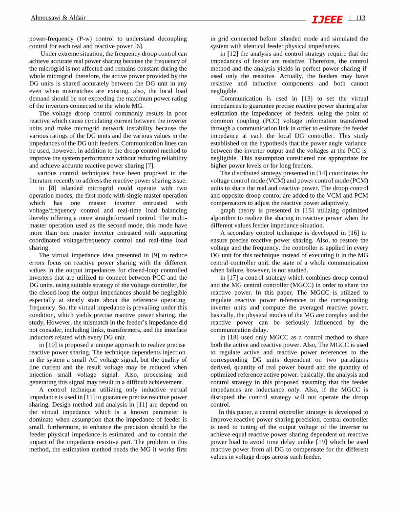
In this paper, the structure of each DG shown in Fig.3, VDC
represented the DC prime mover operating as input for three

Almousawi & Aldair | 115
phase voltage source inverter, where Lf and Cf represented
the filter inductor and filter capacitor, respectively. v
represented the capacitor voltage while i is the inductor
current.
Inner control loop identified as low-level current and
voltage compensators. This loop consists of a filter inductor
current control loop, a filter capacitor voltage control loop
also used, and maintains feed-forward compensators and the
feedback together with the linear control loop. The Clark and
park transformation (ABC-dq0) which be used in this loop.
Fig. 3 local controls and structure of a DG unit
III. POWER SHARING STRATEGY
Completing equivalent reactive power sharing for
islanded system among the DG that are linked to the MG is a
difficult job. When dependent on only local voltage and
current information the inverters cannot compensate for
mismatches in their reactive power productions, since the
working parameters of the other DG are unidentified. To
improve the work of the DG and complete equivalent sharing
of the reactive power request, must be made the MGCC to
adjust the reactive power provided by every DG connected to
the MG.
Every of the loads delivers information to the MGCC
related of the reactive power distributed to the microgrid (
QL1 and QL2 ). The MGCC than determines the quantity of
reactive power that every DG must be provide and adjusts the
reactive power of every DG through an external loop as
illustrate in Fig.3.
To allow good sharing of the reactive power, each inverter
should send the droop gain (n) to the MGCC. This operation
achieved through the setup time only i.e. when the DG is
linked to the MG for the first time. The reactive power
request for each DG can be determined by:
𝑄𝑥∗ =
𝑄𝑙𝑜𝑎𝑑
𝑛𝑥 ∑1𝑛𝑖
3𝑖=1
(7)
where 𝑄𝑙𝑜𝑎𝑑 is the reactive power consumed by all the
loads, the droop gain of inverter x represented by 𝑛𝑥, ∑1
𝑛𝑖
3𝑖=1
is the summation for all droop gains of the DG connected
with MG, and 𝑄𝑥∗ is the reactive power request namely
required to be provided by inverter X.
The MGCC adjusts the reactive power of each inverter by
using PI controllers. PI controllers in this paper, deliver an
extra modification in voltage production which additional to
the droop control output (∆V∗).
IV. SIMULATION RESULTS
In this paper, the case study simulated with program
PSCAD/EMTDC, there are three sequence of actions with
each lasting 4 seconds. Also, The MGCC was assumed to
adjust the voltage reference starting from the beginning of the
simulation. In this paper, two case study discussed: the first
case, the rating of the three DG units have same rating with
different feeder impedance, while another case discussed the
rating of the three DG units with different ratings.
A. First Case
At beginning, the three DGs were operated together with
load 1, while the load 2 were off. Loads were shared between
the inverter’s unit for both real and reactive power load
sharing according to the droop control and the equation (7).
Reactive power when the DG in the same rating was shared
in the same ratio. Additionally, reference points for voltage
inverter output for the droop controllers were determined as
previous discussed and transmitted to the every DGs by the
MGCC.
The rating of each DG in this case (0.2 MVA) while the
load 1 represented the fixed load with (0.27 MW, 0.135
MVAR). At 4 seconds simulation time, the load 2 was turned
on with (0.135 MW, 0.045 MVAR). Also, the real and
reactive power was shared according to droop control and the
equation (7). At 8 seconds, load 2 increased to (0.27 MW,
0.09 MVAR). Table 1 explained the parameters used for both
MG and DG while the results for real and reactive powers,
frequency, and voltage inverter output are shown in Fig. 4
and Fig. 5. Examining the plots in Figs. 4 (a) and (b), notice
that the active and the reactive power was shared accurately.

116 | Almousawi & Aldair
TABLE. 1
MG and DG parameters
Description parameter value
Rating of each DG
system
MVA 0.2
Nominal voltage Vo 480 V (L-L)
Nominal Frequency wo 377 rad/s
Input DC voltage VDC 850 V
Feeder 1 impedance R + J X (𝛺) 1.1 + j 0.434
Feeder 2 impedance R + J X (𝛺) 1.0 + j 0.563
Feeder 3 impedance R + J X (𝛺) 1.2 + j 0.372
(a)
(b)
(c)
Fig. 4 Output of (a) Real power (b) The reactive power (c)
drop frequency for three DG
We note that at the beginning of the simulation, the
transient will be occurring but quickly removed with less than
(0.03 sec.) by controlling ability for each of the real and
reactive power. In this paper, the droop frequency selected as
0.25 Hz and the result as shown in Fig. 4 (c). Also, it can be
seen that the DG3 differs slightly from the DG1 and DG2
because the distance between them.
Fig. (5) shown that the minimum drop voltage occurs when
any new load appears in the MG and then this drop quickly
removed.
(a)
(b)
(c)
Fig. 5 Inverter output voltage for (a) DG1 (b) DG2 (c)
DG3
B. Second Case
In this case, the DG operating with different rating (0.3
MVA for DG1, 0.2 MVA for DG2, and 0.1 MVA for DG3).
The active and reactive power sharing the load according to
rating of each DG with ratio (3:2:1).
At beginning, the three DGs were operated together with
load 1, while the load 2 were off. Loads were shared between
the inverter’s unit for both real and reactive power load
sharing according to the droop control and the equation (7).

Almousawi & Aldair | 117
Reactive power was shared according to ratio. The reference
points for voltage inverter output for the droop controllers
were determined as previous discussed and transmitted to the
DGs by the MGCC. Remaining parameters used the same
parameters in Table 1. The results for real and reactive
powers, frequency, voltage inverter output, and current
inverter output are shown in Fig. 6, Fig. 7, Fig. 8, and Fig. 9.
(a)
(b)
Fig. 6 Output of (a) Real power (b) The reactive power
(a)
(b)
Fig. 7 Output of (a) drop frequency for three DG (b) Zoom
the droop frequency
Fig. 8 Inverter output voltage for DG1, DG2, and DG3
Fig. 9 Inverter output current for DG1
V. CONCLUSION
In this work, an enhanced MG reactive power load sharing
strategy was proposed for parallel DGs in an islanded
microgrid. This strategy uses reactive power load information
to help calculated power sharing according to power rating
for each DG then compared with reactive measurement, the
error of reactive power load sharing is compensated by
utlizing PI controller. The output of PI controller used to
adjust the voltage reference output from each inverter.
Modelling of MG has been established by using
PSCAD/EMTDC. The simulated MG consist of three DG
units with two linear loads. DG operating with the equal
power rating and in this case DG units segment the load
equally. Also, DG operating with the different power rating
and in this case DG units share the load according to rating
for each DG. In two case, the feeder impedance different
from each DG to PCC.
REFERENCES
[1] Wang, Keyou et al. “Decentralized Power Sharing
Control for Parallel-Connected Inverters in Islanded
Single-Phase Micro-Grids.” IEEE Transactions on Smart
Grid 9 (2018): 6721-6730.
[2] Rezaee, Saeed et al. “Accurate and fast power sharing
among inverters in AC microgrids with constant power
loads.” 2017 IEEE 18th Workshop on Control and
Modeling for Power Electronics (COMPEL) (2017): 1-8.
[3] Yang, Jian et al. “A Distributed Cooperative Control
Algorithm for Optimal Power Flow and Voltage
Regulation in DC Power System.” IEEE Transactions on
Power Delivery 35 (2020): 892-903.

118 | Almousawi & Aldair
[4] Guerrero, Josep M. et al. “Advanced Control
Architectures for Intelligent Microgrids—Part I:
Decentralized and Hierarchical Control.” IEEE
Transactions on Industrial Electronics 60 (2013): 1254-
1262.
[5] Afshar, Zakaria et al. “A Novel Accurate Power Sharing
Method Versus Droop Control Include Autonomous
Microgrids With Critical Loads.” IEEE Access 7 (2019):
89466-89474.
[6] Milczarek, Adam et al. “Reactive Power Management in
Islanded Microgrid—Proportional Power Sharing in
Hierarchical Droop Control.” IEEE Transactions on
Smart Grid 6 (2015): 1631-1638.
[7] Guo, Qian et al. “Secondary Voltage Control for Reactive
Power Sharing in an Islanded Microgrid.” (2016).
[8] Chandorkar, M. C. et al. “Control of parallel connected
inverters in stand-alone AC supply systems.” Conference
Record of the 1991 IEEE Industry Applications Society
Annual Meeting (1991): 1003-1009 vol.1.
[9] Yao, Wei et al. “Design and Analysis of the Droop
Control Method for Parallel Inverters Considering the
Impact of the Complex Impedance on the Power
Sharing.” IEEE Transactions on Industrial Electronics 58
(2011): 576-588.
[10] Tuladhar, Anil et al. “Control of parallel inverters in
distributed AC power systems with consideration of line
impedance effect.” (2000).
[11] Li, Yun Wei and Ching-Nan Kao. “An Accurate
Power Control Strategy for Power-Electronics-Interfaced
Distributed Generation Units Operating in a Low-Voltage
Multibus Microgrid.” IEEE Transactions on Power
Electronics 24 (2009): 2977-2988.
[12] Zhong, Qing-Chang. “Robust Droop Controller for
Accurate Proportional Load Sharing Among Inverters
Operated in Parallel.” IEEE Transactions on Industrial
Electronics 60 (2013): 1281-1290.
[13] He, Jinwei et al. “An islanding microgrid reactive
power sharing scheme enhanced by programmed virtual
impedances.” 2012 3rd IEEE International Symposium
on Power Electronics for Distributed Generation Systems
(PEDG) (2012): 229-235.
[14] Wu, Dan et al. “Autonomous active and reactive
power distribution strategy in islanded microgrids.” 2014
IEEE Applied Power Electronics Conference and
Exposition - APEC 2014 (2014): 2126-2131.
[15] Simpson-Porco, John W. et al. “Secondary Frequency
and Voltage Control of Islanded Microgrids via
Distributed Averaging.” IEEE Transactions on Industrial
Electronics 62 (2015): 7025-7038.
[16] Shafiee, Qobad et al. “Distributed Secondary Control
for Islanded Microgrids—A Novel Approach.” IEEE
Transactions on Power Electronics 29 (2014): 1018-
1031.
[17] Zhu, Yixin et al. “Accurate power sharing strategy for
complex microgrid based on droop control method.” 2013
IEEE ECCE Asia Downunder (2013): 344-350.
[18] Bassey, Ogbonnaya et al. “Active and Reactive Power
Sharing in Inverter Based Droop-Controlled
Microgrids.” 2019 IEEE Power & Energy Society
General Meeting (PESGM) (2019): 1-5.
[19] Micallef, Alexander et al. “Secondary control for
reactive power sharing in droop-controlled islanded
microgrids.” 2012 IEEE International Symposium on
Industrial Electronics (2012): 1627-1633.
[20] PES Test Feeder [Online]. Available:
http://sites.ieee.org/pes-testfeeders/resources/