Conductor Sizing Article
159
Outdoor Substation Conductor Ratings Transmission and Substation Design Committee Substation Conductor Rating Task Force PJM Interconnection, LLC December 16, 2004 – Revision 1 PJM Substation Conductor Rating Task Force: Baltimore Gas & Electric Robert W. Munley (Chairman) Allegheny Power Joseph F. Leighty Conectiv William M. Ruggeri FirstEnergy Alan E. Kollar PECO Energy Bernie O’Hara PECO Energy Harry E. Hackman Potomac Electric Power Chih C. Chow PPL Electric Utilities Alan L. Tope Public Service Electric & Gas John Hearon
-
Upload
bhoirsandeep -
Category
Documents
-
view
206 -
download
5
Transcript of Conductor Sizing Article

Outdoor Substation Conductor Ratings
Transmission and Substation Design Committee Substation Conductor Rating Task Force
PJM Interconnection, LLC
December 16, 2004 – Revision 1
PJM Substation Conductor Rating Task Force:
Baltimore Gas & Electric Robert W. Munley (Chairman) Allegheny Power Joseph F. Leighty Conectiv William M. Ruggeri FirstEnergy Alan E. Kollar PECO Energy Bernie O’Hara PECO Energy Harry E. Hackman Potomac Electric Power Chih C. Chow PPL Electric Utilities Alan L. Tope Public Service Electric & Gas John Hearon

Table of Contents
1.0 Scope / Introduction.............................................................................................. 1
2.0 Definitions and Terms .......................................................................................... 2
3.0 Weather Assumptions........................................................................................... 3 3.1 Wind Speed.......................................................................................................... 3 3.2 Wind Direction..................................................................................................... 4 3.3 Ambient Temperature .......................................................................................... 4 3.4 Rating Tables ....................................................................................................... 4 3.5 Solar Gain & Atmosphere.................................................................................... 4
4.0 Method of Calculation .......................................................................................... 5 4.1 Calculating the Current-Temperature Relationship of Conductors ..................... 5 4.2 Description of IEEE Standard 605-1998 ............................................................. 5 4.3 Convective Heat Loss Considerations ................................................................. 6
4.3.1 Natural Convection ..................................................................................... 6 4.3.2 Forced Convection...................................................................................... 7
5.0 Emissivity and Absorptivity............................................................................... 10
6.0 Maximum Conductor Temperature Limitations............................................. 11
7.0 Conductor Materials........................................................................................... 13
8.0 Other Considerations.......................................................................................... 14 8.1 Connections to Station Equipment..................................................................... 14 8.2 Thermal Expansion ............................................................................................ 14 8.3 De-rating of Parallel Busses or Conductors....................................................... 14 8.4 Uneven Loading of Parallel Conductors............................................................ 14
9.0 Fittings and Accessories ..................................................................................... 15
10.0 Rating Assumptions ............................................................................................ 16
11.0 Risk....................................................................................................................... 17
11.1 Normal Ratings .................................................................................................. 20 11.2 Emergency Ratings ............................................................................................ 21
12.0 PJM Method Comparison.................................................................................. 22
13.0 Ampacity Tables.................................................................................................. 28
Appendices..................................................................................................................... 144

December 16, 2004 PJM Substation Conductor Ratings 1
1.0 Scope / Introduction The PJM Transmission and Substation Design Subcommittee (TSDS) was requested to review and update the existing Determination of Ratings for Tubular Bus document issued by the TSDS in August 1979. This document contains ampacity ratings for tubular bus used in substations and was based on calculations performed using a similar methodology and set of parameters determined for transmission line conductors. A task force consisting of representatives from PJM member operating companies was assigned the task of updating the tubular bus ratings. The results of the task force work are incorporated into this new document. The task force utilized the information and methodology contained in IEEE Std 605-1998, “Guide for Design of Substation Rigid-Bus Structures” as a primary reference in developing new ampacity ratings for tubular bus as well as other wire conductors used in substations. The task force analyzed existing industry standards on bus design and line conductor ampacities, and determined the recommended values for the key parameters used in calculating conductor ampacity. Several of the key parameter values used by the task force in the ampacity calculations were changed from the values used in the 1979 tubular bus ratings. This report includes a discussion of the key parameters used in calculating the ampacities of round shaped conductors used in outdoor substations. These parameters include wind speed and direction, ambient temperature, solar gain, emissivity, absorptivity, and maximum conductor temperature limitations for conditions of normal (continuous) and emergency (one hour and 24-hour) ratings. The report also contains a discussion on the calculation methodology, conductor materials, fittings and accessories, other ampacity considerations, and risk associated with wind speed different than assumed for calculations. Lastly, this report includes new revised ampacity ratings for substation conductors used in facilities under the control of PJM. The ratings provided in this document are for outdoor applications of aluminum and copper tubular bus, and bare aluminum and copper wire of various sizes.

December 16, 2004 PJM Substation Conductor Ratings 2
2.0 Definitions and Terms Normal Conditions All equipment in normal configuration, and normally
expected range of ambient weather conditions. Normal Rating The maximum permissible constant load at normal
conditions, at the maximum allowable conductor temperature for that conductor.
Emergency Conditions Equipment has been operating at Normal Rating. The
equipment is then exposed to an out of configuration condition.
Emergency Rating The maximum permissible constant load at emergency
conditions, at the maximum allowable conductor temperature. (for a period longer than 15 minutes, but not to exceed 24 hours)
Weather Conditions Ambient temperature, solar and sky radiated heat flux,
wind speed, wind direction, and elevation above sea level.
Max. Allowable Condr. Temp. The maximum temperature limit that is selected in
order to minimize loss of strength, conductor sag, line losses, or a combination of the above.
Time Risk The time during which the conductor is vulnerable to
operation at temperatures greater than the design temperature.
Temperature Risk The maximum increase in conductor temperature above
design temperature which can be experienced if the conductor carries its rated current simultaneously with an occurrence of the most severe set of ambient conditions.

December 16, 2004 PJM Substation Conductor Ratings 3
3.0 Weather Assumptions
Ambient weather conditions have a major effect on thermal ratings of a substation conductor. There are many factors to consider when determining the precise weather model to utilize in the ampacity calculations of substation bus conductors. However, wind (speed and direction) and ambient temperature are major variables to consider and have the most effect in determining the final thermal ratings of substation conductor. The following sections will outline these major variables that are critical in the calculation of the overall thermal rating. It is important to note that weather data was collected and analyzed in PJM work performed by the original transmission line conductor rating task force in 1973. The weather data included 10 years of data from Pittsburgh from January 1, 1949 through December 31, 1958 and 16 years of data from the Washington D.C. National Airport from January 1, 1949 through December 31, 1964. All of the data was combined to form an hourly composite record that was representative of the entire PJM service territory. The current task force evaluated this original data and believes it to remain representative of the weather conditions that exist within the present PJM territory.
3.1 Wind Speed Wind speed is an important variable in determining the ratings of a substation conductor. The 1979 PJM tubular bus rating document followed the recommendations of the 1973 PJM transmission line rating work and used a zero wind speed in determining the normal rating of bus and 3.38 feet per second (fps) wind speed in determining the emergency rating of bus. These wind speed values were modified from those used for the transmission line rating work to acknowledge that substation environments were more open and less shielded from winds. The current task force has decided to utilize a rating philosophy for substation bus that is more consistent with other substation equipment and depart from ratings based upon different weather conditions that was used previously and is currently used for transmission line conductors. These systems operate in different clearance and safety environments and have different inherent risk limitations and therefore can have different rating assumptions. The operation of substation bus within a fenced in substation which is accessible only by trained personnel is inherently different than a transmission line which crosses a roadway, or public lands. Also, the original PJM bus rating criteria is in contrast to what is recommended in the IEEE Standard 605. Section C.3 (Heat Transfer) in Annex C of the IEEE Standard 605 document states that a wind speed of 2 fps is used for all substation conductor thermal rating calculations. In IEEE Standard 605, it is concluded that assumption of a 2 fps wind is a conservative, yet realistic approach and was chosen for the basis of the IEEE document. In consideration of the above, the present task force recommends that a wind speed of 2 fps be used in the calculation of both normal and emergency thermal ratings of substation conductor and therefore is the basis for the published tables in this document. The inherent risks associated with utilizing this wind speed are discussed in Section 11 of this document.

December 16, 2004 PJM Substation Conductor Ratings 4
3.2 Wind Direction Both the 1979 PJM bus rating work and the IEEE Standard 605 agree in the utilization of a wind perpendicular to the substation conductor. A perpendicular wind (a 90o cross wind) is recommended by this task force for the calculations of substation conductor thermal ratings and is used in the published tables.
3.3 Ambient Temperature Ambient temperature is an important parameter to consider when calculating substation conductor thermal ratings. As stated in the 1979 PJM bus rating document, for the summer rating period, an ambient temperature of 35°C is to be used for substation conductor thermal rating calculations. Examination of the original PJM weather data indicates that the actual summer temperatures are less than or equal to 35°C over 99% of the time. For the winter rating period an ambient temperature of 10°C is to be used for substation conductor thermal rating calculations. This is a reduction in ambient temperature versus the 1979 PJM work (10oC versus 20oC) and is believed to be a conservative, yet realistic selection. Examination of the original PJM weather data indicates that the actual winter temperatures are less than or equal to 10°C over 88% of the time. The composite weather data supporting the above statistics can be found in Section 11. The inherent risk associated with utilizing the various ambient temperature parameters can be found in Section 11 of this document.
3.4 Rating Tables The rating tables for each type of substation conductor will provide a specific thermal rating based on the wind and ambient temperature recommendations discussed above. The tables are ambient temperature adjusted so as to allow the system operator to determine the ampacity of a substation conductor based on real time information known at that specific time. Each table provides thermal ratings based on ambient temperatures from -15°C to +40°C in 5° increments.
3.5 Solar Gain & Atmosphere The model utilized by the PJM task force is based upon the solar gain (solar heating) equations used in both IEEE Standard 605 and IEEE Standard 738-1993 “IEEE Standard for Calculating the Current-Temperature of Bare Overhead Conductors”. Both of these standards allow for adjustments in solar gain effects due to varying atmosphere clarity. The atmosphere clarity varies between a clear atmosphere and a hazy industrial atmosphere. The clear atmosphere allows for more solar heating of the bus conductor and results in a slightly lower bus ampacity rating when compared to the industrial atmosphere assumption. The bus ampacity tables published in IEEE Standard 605 are based upon a clear atmosphere. Utilizing this flexibility, the task force has chosen to utilize a clear atmosphere for ampacity calculations as defined by IEEE Standards 738 and 605. The task force believes this is a conservative, yet realistic approach and was chosen for the basis of this document.

December 16, 2004 PJM Substation Conductor Ratings 5
4.0 Method of Calculation
4.1 Calculating the Current-Temperature Relationship of Conductors Early in its deliberations, The PJM Tubular Bus Rating Task Force recognized that an updated method of calculating conductor ratings was needed to replace the original computer code that was written in FORTRAN in August 1979. Another goal of the task force was to have a user-friendly program that could operate in today’s PC oriented office environment.
The task force selected the method of IEEE Standard 605. Copies of the standard are widely available and earlier IEEE source documents discuss the calculations in greater detail than the standard. IEEE Standard 605 is widely accepted as a standard within the industry and forms a commonly accepted basis for calculations. With this in mind, the task force developed a Microsoft Excel © Spreadsheet to accommodate a wide base of possible users. The spreadsheet applies the IEEE Standard 605 approach to these calculations for use by all PJM member companies.
4.2 Description of IEEE Standard 605-1998 This standard presents a method of calculating the current-temperature relationship of bare substation rigid-bus conductors based on a 2 fps wind perpendicular to the length of the conductors. The authors of the standard chose a 2 fps wind because it was, “conservative, yet realistic” and had the additional advantage of simplifying many of the equations.
The conductor temperature is a function of:
a. Conductor material b. Conductor diameter c. Conductor surface condition d. Ambient weather conditions e. Conductor electrical current
IEEE Standard 605 includes mathematical models to calculate conductor temperatures and conductor thermal ratings. The standard contains calculated tables with numerous temperature-current relationships for specific conductors (materials and shapes) and weather conditions, in all cases with a 2 fps wind present. Each user of the standard must assess which weather data and conductor characteristics are appropriate for his needs.
The source document for the ampacity calculation and table portion of IEEE Standard 605, PAS 96, No. 4, July/August 1977, Page 1341, “Thermal Considerations for Outdoor Bus Conductor Design Ampacity Tables,“ notes an elevation of sea level was used in preparing the ampacity tables. Conductor temperatures ranged from 70 °C to 150 °C. Ambient temperature was 40 °C.
The equations relating electrical current to conductor temperature may be used in either of the following two ways:
• To calculate the conductor temperature when the electrical current is known • To calculate the current for a given conductor temperature (by iteration)

December 16, 2004 PJM Substation Conductor Ratings 6
The Standard’s approach to calculating ampacity requires first calculating the convective heat loss (qc), the radiation loss (qr), and the solar heat gain (qs), of the conductor under investigation. Since the Task Force decided that calculations should be able to be performed at any wind speed, the convection equations contained in IEEE Standard 605 were modified to be suitable for variable wind speeds. The modifications were based on IEEE Standard 738. Since both standards use the same sets of equations to calculate the radiation loss and the solar heat gain, the balance of this discussion will focus on convective heat loss considerations.
4.3 Convective Heat Loss Considerations Convective heat loss, or the cooling due to air movement, is a major factor in determining the thermal rating of a conductor. There are two conditions to consider: (a) cooling due to natural convection – or a zero wind speed, and (b) cooling due to forced convection – or a non-zero wind speed. This section reviews material taken from IEEE Standards 605 and 738, to permit bus ampacity calculations for any wind speed.
4.3.1 Natural Convection Natural convection applies to surfaces shielded from direct exposure to the wind. Assuming, however, that there is enough space for natural convection to occur, then surface heat loss can be calculated using generally accepted equations for natural convection. In Section C.3.2.3, IEEE Standard 605 (Substation Rigid-Bus Structures) gives equation (1.) below for natural convection over a cylindrical surface:
(1.) qc = 0.0022 * ∆T 1.25 * l -0.25 *A
∆T = temperature difference between the conductor surface and the surrounding air in degrees Celsius.
l = length of conductor surface in inches = 12 for a one foot length of conductor.
A = conductor surface area in inches2 / foot length. qc = convective heat loss in watts per linear foot.
Let’s turn this into a more useful equation that can be put into a spreadsheet and used to calculate qc.
A = area = π * D * 12 in2 / ft l = length of conductor surface in inches = 12 * L = 12 Substituting into (eq. 1.) gives: qc = 0.0022 * ∆T 1.25 * 12 -0.25 * 12 * π * D qc = 0.0022 * ∆T 1.25 * 20.255166 * D (2.) qc = .044561 * D * ∆T 1.25 watts / ft

December 16, 2004 PJM Substation Conductor Ratings 7
By comparison, IEEE Standard 738 (Bare Overhead Conductors) explicitly recognizes more of the factors involved in natural convection heat loss. As noted in Section 2.4.4 of that Standard:
(3.) qc0 = .283 * ρr0.5 * D0.75 * ∆ T1.25 watts/ft
qc0 = convective heat loss due to zero wind ρr= density of air in lb/ft3
D= conductor outer diameter in inches ∆T= temperature difference between the conductor surface and the surrounding air in degrees Celsius
Since the spreadsheet developed by the task force is based on the work of the previous Conductor Rating Task Force, equation (3.) above is used. This facilitates recognizing the effect of elevation upon conductor ratings (higher elevation results in lower air density and therefore lower heat transfer, all else being equal.).
4.3.2 Forced Convection IEEE Standard 605, section C.3.2 2 gives the following equation for heat transfer where there is a 2 fps wind.
(4.) qc = .010 * (D -0.4 ) * A * ∆T
D = outer diameter of cylinder in inches A = surface area of cylinder in inches2 per foot length ∆T = temperature difference in degrees Celsius between the conductor surface and the ambient air temperature.
Remembering that the surface area of a 12 inch long cylinder = 12 * π * D and then substituting in equation (4.) gives:
(5.) qc = 0.376991 * D 0.6 * ∆T
This equation, again, is valid only for a 2 fps wind. As stated in section C.3 of IEEE Standard 605, an assumption of a 2 fps wind is a conservative, yet realistic approach, and it will be used in the examples given herein. IEEE Standard 738 notes in section 2.6.1.2, “Since the wind velocity is greater than 0 ft/second, the forced convection heat loss for perpendicular wind is calculated according to equations (6a.) and (6b.) corrected for wind direction, and compared to the natural convection heat loss. The larger of the heat losses due to both natural and forced convection is then used in calculating the thermal rating.”
(6a.) qc1 = [ 1.01 + 0.371 * (3600 D ρr V/µr)0.52 ] * kf * (Tc – Ta)
(6b.) qc2 = .1695 * (3600 D ρr V/µr) 0.52 * kf * (Tc – Ta)
where V = wind velocity in feet per second.

December 16, 2004 PJM Substation Conductor Ratings 8
Taking this guidance leads to the conclusion that the proper method of calculating qc is to use the specific equations for qc0, qc1, and qc2 and then pick the one yielding the greatest value. To recap, qc0 is the convective heat loss due to zero wind, and qc1 is the convective heat loss due to low wind velocity. The qc1 equation applies at low wind speeds, but gives values that are too low at high wind speeds. qc2 is the convective heat loss due to high wind speed. This equation gives values that are too low at low wind speeds. Hence the largest heat loss value is chosen In the spreadsheet, the following equations will be used for the calculations:
qc = Maximum ( qc0, qc1, and qc2 )
qc0 = Equation (3.) = .283 * ρr0.5 * D0.75 * ∆ T1.25 watts/ft
qc1 = Equation (6a.) = [ 1.01 + 0.371*( 3600 D ρr V/µr)0.52 ] * kf * (Tc – Ta) watts/ft
qc2 = Equation (6b.) = .1695 * (3600 D ρr V/µr) 0.52 * kf * (Tc – Ta) watts/ft
The tables below compares the values of qc obtained for a 2 fps wind speed using the equations of IEEE Standard 605 and the Task Force’s spreadsheet for various diameter tubes.
6” Diameter Tubes Tc Ta qc 605 qc spreadsheet 605/spreadsheet 60 40 22.09 21.29 3.77% 80 40 44.19 42.34 4.36% 100 40 66.28 63.16 4.94% 120 40 88.37 83.78 5.48% 150 40 121.51 114.36 6.26% 180 40 154.65 144.46 7.06%
4” Diameter Tubes Tc Ta qc 605 qc spreadsheet 605/spreadsheet 60 40 17.32 16.70 3.73% 80 40 34.64 33.20 4.35% 100 40 51.97 49.52 4.94% 120 40 69.29 65.69 5.48% 150 40 95.27 89.66 6.26% 180 40 121.26 113.34 6.98%

December 16, 2004 PJM Substation Conductor Ratings 9
2” Diameter Tubes
Tc Ta qc 605 qc spreadsheet 605/spreadsheet 60 40 11.43 11.09 3.05% 80 40 22.86 22.15 3.19% 100 40 34.29 33.19 3.30% 120 40 45.71 44.22 3.38% 150 40 62.86 60.76 3.45% 180 40 80.00 77.28 3.52%
In conclusion, the qc calculation in the spreadsheet gives qc values that are between 3% and 7% lower than those calculated by the formula of IEEE Standard 605. The practical impact of these upon conductor ampacity is minimal, as shown in the tables below. These tables compare the spreadsheet against the values in IEEE Standard 605, Table B.3 for schedule 40 aluminum (6063 alloy – 53.0 % conductivity) tubular bus at a 40oC ambient at sea level. The small differences are attributable to rounding errors, errors due to curve fitting to data in the standard, and unavailability of the actual conductor constants that were used in preparing the original tables.
6” Diameter Tubes
4” Diameter Tubes
2” Diameter Tubes Conductor Temperature
Size 80oC 90 oC 100 oC 110 oC 140 oC 150 oC 2” from 605 1217 1402 1561 1703 1949 2161 2” spdsht 1235 1413 1566 1702 1942 2150 Difference 18 amps 11 amps 5 amps -1 amp -7 amps -11 amps
Conductor Temperature Size 80oC 90 oC 100 oC 110 oC 140 oC 150 oC
6” from 605 3771 4435 5003 5506 6382 7144 6” spdsht 3876 4506 5047 5528 6366 7096 Difference 105 amps 71 amps 44 amps 22 amps -16 amps -48 amps
Conductor Temperature Size 80oC 90 oC 100 oC 110 oC 140 oC 150 oC
4” from 605 2534 2954 3315 3535 4192 4675 4” spdsht 2589 2990 3335 3642 4176 4640 Difference 55 amps 46 amps 20 amps 7 amps -16 amps -35 amps

December 16, 2004 PJM Substation Conductor Ratings 10
5.0 Emissivity and Absorptivity
For all ampacity calculations within this guide the emissivity and absorptivity of rigid bus conductors are considered to be equal. The values used for emissivity and absorptivity for copper bus are 0.85 and for aluminum bus are 0.50. These values are typical after extended outdoor exposure resulting in weathered conductors and are in alignment with IEEE Standard 605. The values of emissivity and absorptivity used in the original PJM document for tubular bus were based upon tests made on stranded aluminum conductors. As stated above, the task force has chosen to utilize the values for emissivity and absorptivity from IEEE Standard 605. These changes have a small impact on the ampacity of the bus. For stranded aluminum and copper conductors used in a substation, an emissivity value of 0.7 and an absorptivity value of 0.9 will be used for both materials. These values are based on the 1973 study titled “Determination of Bare Overhead Conductor Ratings” and are identical to the values used in the previous tubular bus rating guide.

December 16, 2004 PJM Substation Conductor Ratings 11
6.0 Maximum Conductor Temperature Limitations
It is extremely important to choose conductor operating temperatures that will enable the conductor to operate without any significant reduction in mechanical strength or life. Many studies have been performed to determine the temperatures at which conductors can operate without loss of strength or life. ECAR (East Central Area Reliability) report 74-TFP-37, “Transmission Conductors Loss of Strength Due To Elevated Temperature”, and report 74-EEP-42, “A Uniform Method For the Determination of Load Capability of Line Terminal Equipment” have both been used to assist the task force in selecting the recommendations for substation conductor maximum operating temperatures. Much of the information in this section of the report has been taken from the referenced ECAR reports. When selecting the maximum temperature at which a conductor is to operate, one must consider the annealing characteristic of the conductor. The annealing process causes a loss of the conductor strength. A loss in strength occurs whenever the conductor is exposed to elevated temperature operation for a period of time. After a conductor is operated at an elevated temperature, there is no recovery of the amount of strength lost when the conductor is allowed to cool. Additional loss of strength from subsequent heating cycle will begin with the loss established by the previous heating cycle and will continue to accumulate as long as the elevated temperatures exist. The amount of loss of strength will increase rapidly under extreme emergency operating conditions and can be calculated if sufficient information on the conductor materials and operating history is available with respect to temperatures experienced and the duration of the exposure. ECAR report 74-TFP-37 provides a method for performing these calculations. Conductor loss of strength is a function of the conductor temperature and the duration of time the conductor is at that temperature. For stranded conductors, factors considered in the determination of conductor loss of strength include the loss of strength factor, the strength ratio of conductor components, the strength adjustment due to stranding of cabling factor, and the adjustment to test strand data. The loss of strength factor is a percent loss of strength of test strands taken from suppliers’ data. The ratios of the strength of each component part of a cable to the total strength of the cable are given in ECAR report 74-TFP-37, and reflect the composite effect of the rated strength of strands, cabling reduction, and metal proportions. The cabling process reduces the effective strength of the individual components of the cable relative to the sum of the individual strands. This factor is given by ASTM standards. The adjustment to test strand factor is needed since the entire cable is composed of strands that may not be of identical type and strength. The initial strength of strands is a function of the cold drawing process at the wire mill. The final strength in the fully annealed state is related only to the metal alloy. Consequently, the portion of the initial strength that can be lost through annealing will be greater for the higher strength strands than for the lower strength strands. The conductor temperature limitations chosen by the task force are based on ECAR report 74-EEP-42. The temperature limits are based on the annealing characteristics of hard-drawn copper and two representative aluminum conductor materials. The maximum

December 16, 2004 PJM Substation Conductor Ratings 12
normal conductor temperatures chosen are based on a normal temperature limit at which operation at this temperature will result in no reduction of conductor strength. The normal operating temperatures chosen are 75oC for copper wire, 90oC for aluminum and copper tube, and 105oC for aluminum wire (AAC, AAAC, ACAR, & ACSR). The maximum 24 hour conductor emergency operating temperatures chosen are based on a temperature limit at which operation at this temperature for 24 hours will rarely result in more than one percent loss of strength. The emergency 24 hour operating temperatures chosen are 95oC for copper wire, 115oC for aluminum and copper tube and 130oC for aluminum wire. The maximum one hour conductor emergency operating temperatures chosen are based on a temperature limit at which operation at this temperature for one hour will rarely result in more than one percent loss of strength. The emergency one hour operating temperatures chosen are 110oC for copper wire, 130oC for aluminum and copper tube, and 140oC for aluminum wire. A ten to fifteen percent loss of initial conductor tensile strength over the lifespan of the conductor is considered to be the limit for maintaining safe mechanical integrity of the conductor.

December 16, 2004 PJM Substation Conductor Ratings 13
7.0 Conductor Materials
Copper and aluminum are the main basic materials used in commercial manufacturing of most types of electrical conductors for current carrying applications in electric power systems. Conductivity standards of copper (percent International Annealed Copper Standard (IACS)1) apply to pure copper in the annealed or unrestrained condition, for as the metal is cold worked its resistance is increased and conductivity decreased. The cold working of copper greatly increases its ultimate tensile strength. Likewise, greater strength is obtained if certain alloying ingredients are added, but its conductivity is decreased. Commercial hard drawn copper conductor is considered as having conductivity of 97% IACS. Pure aluminum has an electrical conductivity of 65% IACS. Commercial high-purity aluminum alloys such as 1350, 6063 and 6061 are the forms of aluminum most widely used for electrical conductors. They have a conductivity of approximately 61, 53 and 41 % IACS respectively. Again, greater strength is obtained if certain alloying ingredients are added, but its conductivity is decreased. Aluminum conductors are manufactured to meet appropriate ASTM (American Society for Testing and Materials) specifications. In general, a high strength metallic alloy can only be produced at the expense of conductivity. Conversely, a high conductivity metallic alloy can only be produced at the expense of high strength. Improvement of strength may be achieved by: addition of alloying elements, cold working, or heat treatment (i.e. temper). The task force has decided to publish ampacity tables for various sized of copper and aluminum tube and wire. These tables are included in Section 13 of this document.
1 Note : International Annealed Copper Standard (IACS) – In 1913 the International Electro-Technical Commission established an annealed copper standard (IACS) which in terms of weight resistivity specifies the resistance of a copper wire one meter long that weighs one gram. The reference temperature is taken to be at 20ºC.

December 16, 2004 PJM Substation Conductor Ratings 14
8.0 Other Considerations
The purpose of this document is to define the ampacity rating method to be used for substation conductors. It is not intended to be a comprehensive bus design standard. Other elements of bus design are the responsibility of the design engineer. Some of the other elements that need to be considered are described below:
8.1 Connections to Station Equipment Bus ratings within this document are based on maximum allowable conductor temperatures over the specified time period to prevent significant loss of conductor strength. It is important to recognize that the heat generated by a bus conductor may be conducted to any attached equipment. While fittings and connectors often act as heat sinks and can dissipate heat generated by the bus, equipment temperature limitations must be considered to insure proper bus design. Equipment temperature limitations should be obtained from the applicable specification or equipment manufacturer.
8.2 Thermal Expansion Bus conductors expand and contract as their temperature changes. This expansion and contraction, if not properly designed for, can induce significant loadings on bus supports. For long bus spans, provisions should be made to allow for expansion and contraction of bus conductors over the operating temperature range through the use of expansion fittings.
8.3 De-rating of Parallel Busses or Conductors All ratings within this guide apply to bus configuration with one conductor per phase and sufficient spacing between phases as to not impact the conductor rating. When more than one conductor per phase is used and the conductors are in close proximity, the conductors’ ability to radiate heat is reduced. Consequently, the ampacity of the bus conductor is reduced. In these situations an appropriate ampacity rating reduction should be taken.
8.4 Uneven Loading of Parallel Conductors Parallel conductors are often used to increase the ampacity of a bus. Depending on their physical configuration, mutual inductance between conductors can result in an impedance imbalance and uneven loading. The uneven loading of parallel conductors should be considered when calculating the overall ampacity rating of the bus.

December 16, 2004 PJM Substation Conductor Ratings 15
9.0 Fittings and Accessories
The 1979 PJM Tubular Bus Rating task force contacted several manufacturers and electric utility companies to determine the effect of elevated temperatures on bus fittings and accessories. Replies confirmed that properly installed bus fittings and accessories can be operated at temperatures up to 120oC without incurring either electrical or mechanical limitations. Several tests conducted by manufacturers showed that many conductor accessories operated at temperatures 50oC to 100oC lower than the conductor when operating at temperatures above 180oC. This property is mainly dependent on the large mass and surface area of the fittings. The current PJM Tubular Bus Rating task force believes this information to still be valid. Overall, the quality of workmanship installing the fittings and accessories will directly affect the ability to operate at elevated temperatures. Therefore, it is imperative that fittings and accessories be properly installed in accordance with manufacturer’s recommendations to insure the desired performance.

December 16, 2004 PJM Substation Conductor Ratings 16
10.0 Rating Assumptions
Assumptions for Calculations shown in the results tables
Design Ambient Temperatures 35oC summer 10oC winter
Ambient Temperature Range -15oC to 40oC
Wind Speed 2 Ft. per sec. (Normal & Emergency)
Wind Direction 90o to the conductor
Maximum allowable conductor Temp. range 70oC to 140oC (table 12-1, pg. 23)
Solar / Sky Radiated Heat Flux Day Time / Clear
Elevation 1000 Ft. above sea level
latitude 40o North Latitude
Sun Time 14:00 Hrs. Maximum normal operating temperature Aluminum tube 90oC
Aluminum wire 105oC # Copper tube 90oC Copper wire 75oC
Maximum emergency (up to 24 hours) operating temperature Aluminum tube 115oC #
Aluminum wire 130oC # Copper tube 115oC # Copper wire 95oC #
Maximum SHORT TERM (up to 1 hour) emergency operating temperature Aluminum tube 130oC #
Aluminum wire 140oC # Copper tube 130oC # Copper wire 110oC #
# Since heat generated in the bus conductor may be conducted to attached equipment, allowable conductor temperatures may be governed by the temperature limitations of the attached equipment. Equipment temperature limitations should be obtained from the applicable specification or equipment manufacturer.

December 16, 2004 PJM Substation Conductor Ratings 17
11.0 Risk
As discussed previously, bus conductor ratings are affected by many factors. The most significant of these is wind speed. Unlike many of the other factors such as absorptivity, ambient temperature, conductor resistance, etc., wind speed is truly variable in magnitude and direction. In the early PJM work on transmission line conductors, summarized by the “Determination of Thermal Ratings for Bare Overhead Conductor, 1973”, weather data was collected from Washington DC over a period of 16 years, and from Pittsburgh over a 10 year period. These data were pooled to represent a 26-year span of conditions in the PJM service territory. The weather data were summarized on pages A18 and A19 in the 1973 Report in a table format for the frequency distribution of wind and ambient temperature conditions. The tables are reprinted below. In these tables each row lists the probability of occurrence of a given wind speed at a specified ambient temperature. Alternately, each row gives the probability of occurrence of different ambient temperatures given the particular wind speed.
COMPOSITE WEATHER DATA PITTSBURGH AND WASHINGTON, D.C.
PITTSBURGH 1/1/49 – 12/31/58 - 10 YEARS NATIONAL AIRPORT 1/1/49 – 12/31/64 - 16 YEARS TOTAL COMPOSITE HOURLY RECORD - 26 YEARS
FREQUENCY OF OCCURRENCE (PERCENT)
SUMMER DAYS
WIND SPEED-KNOTS AMBIENT TEMP.°C 0 1 2 3 4 5 OVER 5
0 0.009 0.025 0.042 0.024 0.059 0.070 1.830 5 0.038 0.115 0.195 0.247 0.326 0.427 6.455 10 0.059 0.176 0.299 0.345 0.519 0.634 8.811 15 0.070 0.209 0.355 0.484 0.741 0.955 11.147 20 0.103 0.311 0.528 0.655 1.049 1.401 14.559 25 0.109 0.324 0.550 0.791 1.405 1.743 17.949 30 0.059 0.178 0.302 0.496 0.962 1.381 14.708 35 0.012 0.034 0.058 0.127 0.261 0.389 4.650
Over 35 0.000 0.001 0.001 0.003 0.009 0.010 0.187 Total 0.459 1.373 2.330 3.172 5.331 7.010 80.296
SUMMER NIGHTS
WIND SPEED-KNOTS AMBIENT TEMP.°C 0 1 2 3 4 5 OVER 5
0 0.031 0.090 0.153 0.114 0.248 0.271 2.998 5 0.125 0.373 0.632 0.659 0.921 1.135 8.495
10 0.174 0.524 0.887 0.987 1.340 1.453 10.003 15 0.257 0.773 1.312 1.174 1.654 2.089 11.975 20 0.351 1.020 1.730 1.582 2.254 2.600 13.952 25 0.236 0.711 1.207 1.671 2.205 2.582 12.846 30 0.037 0.112 0.188 0.342 0.426 0.516 2.490 35 0.000 0.001 0.002 0.006 0.013 0.011 0.064
Over 35 0.000 0.000 0.000 0.000 0.000 0.000 0.000 Total 1.211 3.604 6.111 6.535 9.061 10.657 62.823
Note: Data is taken from page A-18 of 1973 PJM Report, “Determination of Thermal Ratings for Bare Overhead Conductors”.

December 16, 2004 PJM Substation Conductor Ratings 18
COMPOSITE WEATHER DATA PITTSBURGH AND WASHINGTON, D.C.
PITTSBURGH 1/1/49 – 12/31/58 - 10 YEARS NATIONAL AIRPORT 1/1/49 – 12/31/64 - 16 YEARS TOTAL COMPOSITE HOURLY RECORD - 26 YEARS
FREQUENCY OF OCCURRENCE (PERCENT)
WINTER DAYS
WIND SPEED-KNOTS AMBIENT TEMP.°C 0 1 2 3 4 5 OVER 5
0 0.105 0.321 0.541 0.751 1.315 1.649 22.146 5 0.233 0.695 1.184 1.633 2.380 2.912 31.418 10 0.118 0.354 0.600 0.875 1.079 1.351 16.749 15 0.046 0.134 0.230 0.282 0.344 0.433 7.302 20 0.007 0.023 0.039 0.062 0.062 0.082 2.164 25 0.000 0.000 0.000 0.003 0.000 0.003 0.348 30 0.000 0.000 0.000 0.000 0.000 0.000 0.007 35 0.000 0.000 0.000 0.000 0.000 0.000 0.000
Over 35 0.000 0.000 0.000 0.000 0.000 0.000 0.000 Total 0.509 1.527 2.594 3.606 5.180 6.430 80.134
WINTER NIGHTS
WIND SPEED-KNOTS AMBIENT TEMP.°C 0 1 2 3 4 5 OVER 5
0 0.287 0.856 1.453 1.581 2.709 3.038 27.265 5 0.450 1.345 2.282 2.778 3.286 3.592 28.548 10 0.136 0.411 0.791 0.709 0.884 1.073 10.873 15 0.023 0.078 0.132 0.151 0.213 0.190 3.953 20 0.004 0.008 0.016 0.004 0.012 0.012 0.918 25 0.000 0.000 0.000 0.000 0.000 0.000 0.008 30 0.000 0.000 0.000 0.000 0.000 0.000 0.000 35 0.000 0.000 0.000 0.000 0.000 0.000 0.000
Over 35 0.000 0.000 0.000 0.000 0.000 0.000 0.000 Total 0.900 2.698 4.674 5.223 7.104 7.905 71.565
Note: Data is taken from page A-19 of 1973 PJM Report, “Determination of Thermal Ratings for Bare Overhead Conductors”. When rating bus conductors, the choice of wind speed used is important due to the significant effect on the rating. While a higher wind speed is desired for the higher rating, there is a cost. What happens if the wind speed that actually occurs at the substation is less than the assumed value? As the original PJM work showed, the wind speed is characterized by a distribution of wind speeds with higher and lower values. A wind speed lower than assumed would result in a higher bus temperature than designed. For example, if a rating were based upon 100°C with 2 feet/sec. of wind and a lesser wind were to occur it would cause an increase in conductor temperature to a temperature above 100°C. The risk due to the magnitude of the over temperature condition is called temperature risk.

December 16, 2004 PJM Substation Conductor Ratings 19
The duration of these lower wind speeds is also of concern. The acceptability of a particular temperature risk changes with the duration of that risk. For example, while a temperature overrun of 25°C would not be of major concern for 5 minutes, it would be more problematic if it were for 6 hours during mid-day. The risk due to the duration of the over temperature condition is called time risk. The figure shown below illustrates these risks. On the horizontal axis are listed the wind speeds that could be used for the basis of a bus rating. On the left vertical axis are the bus temperatures that would result if the assumed wind conditions were not achieved. On the right are the durations for the wind speeds at or less than the rated values. For example with a rating of a section of 2” aluminum bus based upon 90oC and a wind speed of 2 feet per second, for times when the wind speed drops below 2 fps, the bus could rise in temperature up to approximately 115oC and may experience overheating above 90oC for about ¼% of the time. From this chart it can be seen that the magnitude of over temperature condition is higher with small bus sizes, and reduced with large bus sizes. Additionally, it can be seen that the duration of an over temperature condition does not vary by bus size.
While the original PJM transmission line work evaluated these risks and developed a reasonable approach to manage these risks using normal ratings based upon 0 knots of wind, this approach is not applicable for substation bus conductor. It is not appropriate for substation ratings because transmission conductors are often sag limited. The maximum sags are controlled by operating and legal limitations. For substation bus, sag limitations do not typically exist, but thermal expansion issues and loss of mechanical strength is of concern.
Aluminum Bus Temperature & Time Risk
90100110120130140150160170180190
0 2 4 6 8Wind Speed (FPS)
Bus
Tem
pera
ture
(C)
012345678
4" Max.Bus Temp 2" Max.Bus Temp Max. Duration of Overheating
Ris
k D
urat
ion
(hrs
) for
ove
rhea
ting
the
bus
base
d on
loss
of
assu
med
win
d sp
eed
0.3 hrs

December 16, 2004 PJM Substation Conductor Ratings 20
11.1 Normal Ratings The task force recommends normal ratings based upon 2 fps at normal bus operating temperatures of 90oC for aluminum tube, 105oC for aluminum wire, 90oC for copper tube, and 75oC for copper wire. These temperatures have been chosen to generally mitigate loss of mechanical strength of the aluminum or copper conductors through annealing. This philosophy includes an inherent temperature risk of overheating that can be quantified. For example, 4” schedule 80, 6063 aluminum bus has a proposed summer normal rating of 3713 amperes. This is based on a 35oC ambient temperature, a wind of 2 fps, and a bus operating temperature of 90oC. If during this period the wind speed were to fall to zero, then the bus temperature would rise due to the decrease in heat loss from the bus. In this case the bus temperature would rise to approximately 108oC. This represents a temperature risk of 18oC. While this may be relatively small, ratings based upon higher wind speeds will have commensurately higher temperature risk. The substation designer must consider the magnitude of temperature risk when designing for expansion and contraction of the bus over the wide range of possible operating temperatures. The temperature risk will change with changes in bus conductor size.
Once the temperature risk has been evaluated, the next logical question is how long will this over temperature condition exist. There are discrete probabilities that exist for weather conditions that will cause an overheated conductor based upon the assumed conditions. For a summer time assumed ambient temperature of 35oC and a wind speed of 2 fps, there is a possibility that the ambient temperature could actually be higher than 35oC and winds at or below 2 fps. From the composite weather figures shown earlier, it is possible to calculate the joint probability of summer daytime temperatures above 35oC and wind speeds of 2 fps. It is also possible to calculate the joint probabilities of occurrence for lesser wind speeds and ambient temperature combinations that result in bus overheating. These probabilities can then be summed to calculate the total probability of bus overheating for an assumed set of ambient conditions such as 35oC and 2 fps of wind. For the 4” aluminum bus described above, this calculation summing probabilities result in any bus overheating above 90oC yields a 0.3% duration of risk for summer daylight hours. Assuming 15 daylight hours per day in the summer time, and 180 days of summertime rating, this equates to 8 hours of risk per year.
Therefore, the bus conductor could be expected to overheat by up to 18oC for up to 0.3% of the time or about 8 hours per summer. This quantifies the magnitude of temperature and time risk in this example. In reality the probability is small of the bus operating at the rated load concurrently and with less than assumed wind.
Based on this type of analysis, it is possible to calculate the cumulative time and temperature risk for a 40 year expected lifetime of substation bus, and use these results to make a judgment about any concerns of loss of bus strength due to annealing. The task force believes the time and temperature risk in the magnitude depicted in this example does not represent a significant design concern for the substation bus conductor. The substation designer must make this evaluation for each individual substation design to determine what maximum operating temperature to utilize.

December 16, 2004 PJM Substation Conductor Ratings 21
11.2 Emergency Ratings Emergency ratings are provided for abnormal out of configuration system conditions. The duration of emergency conditions is much shorter, and based upon previous PJM work on transmission line conductors; PJM assumes emergency operations could exist for up to 4 hours per year. This is also a reasonable assumption for substation bus conductors. To help manage abnormal conditions, emergency ratings with durations of 24 hours and 1 hour are provided by this document. While there is some non-zero additional time and temperature risk that is accumulated by emergency operation, the various emergency operating temperatures (95oC, 115oC and 130oC) do not significantly increase loss of strength from annealing above the values previously described because the duration of temperatures above normal operating temperatures are small in the overall bus lifespan. The concern with emergency operations at high temperature becomes the adequate management of the expansion of the bus. Emergency rating periods are not to exceed 24 hours.

December 16, 2004 PJM Substation Conductor Ratings 22
12.0 PJM Method Comparison
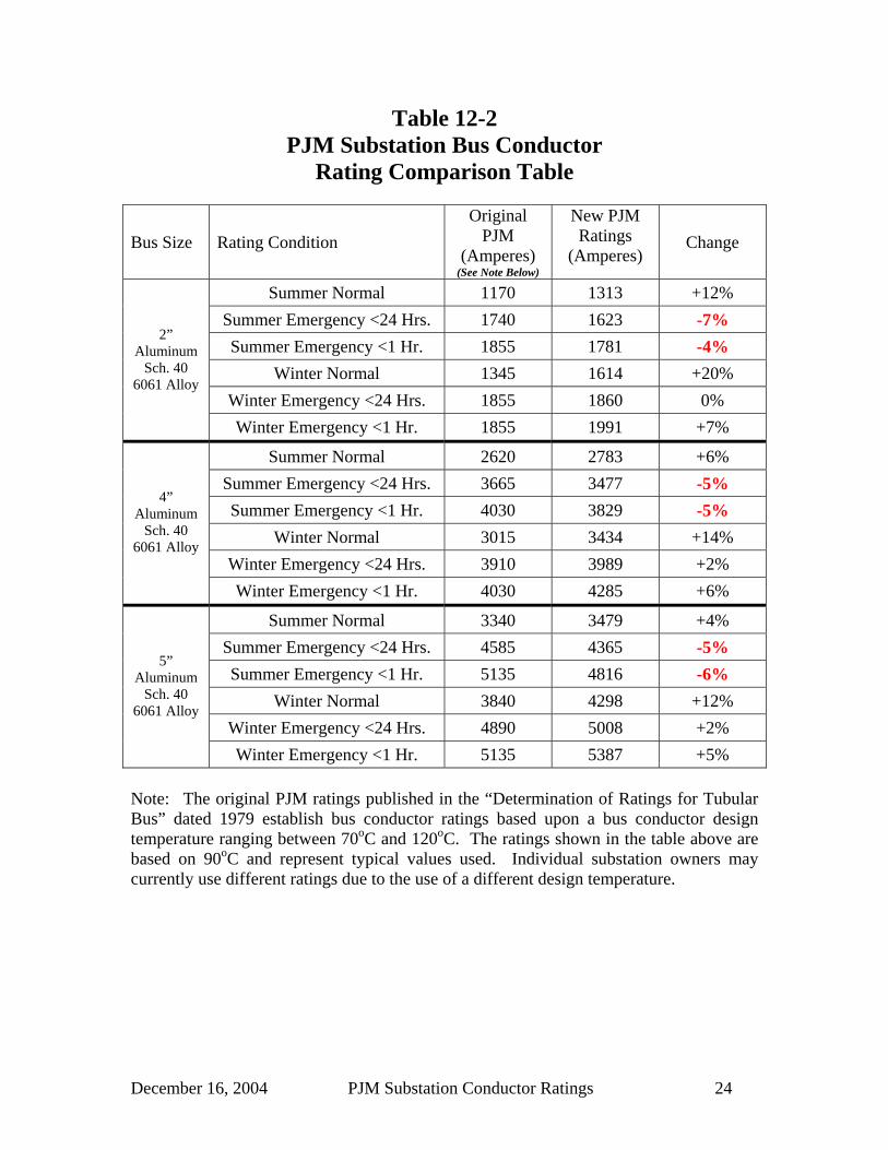
In the previous sections, the task force has detailed the changes recommended in the method and parameters for the calculation of substation bus conductor ratings. Table 12-1 summarizes the changes in input parameters and provides a qualitative impact to the ratings for the change. The effect of any change in individual parameter should not be considered excessively, but the cumulative effect of all of the changes needs to be evaluated. Table 12-2 summarizes the effective changes in ratings for 3 sizes of aluminum tubular bus between the original PJM ratings and the proposed ratings recommended in this document. It can be seen from the table that while the new ratings generally show an increase in capability when compared to the original PJM ratings, the table shows that there is a reduction in rating by between 5% and 8% for summer emergency conditions. The task force generally believes this reduction to be tolerable for a number of reasons. Firstly, some utility companies utilize the normal ratings for both normal and emergency conditions which render this concern meaningless. Second, some utility companies utilize a lower bus design temperature which provides a lower rating and therefore eliminates the concern. The task force believes that there will be an inherent variance between any old method and a new one due to rounding issues, and variability in the bus resistance and temperature values. As a result of these alone, the task force believes that ratings that are within a few percent tolerance essentially represent identical ratings. As a result, the 5% to 8% reduction shown for summer emergency conditions in Table 12-2 are thought to be of little concern.

December 16, 2004 PJM Substation Conductor Ratings 23
Table 12-1 PJM Substation Bus Conductor Ampacity Parameter Summary
Parameter Original PJM Value
New PJM Value
Resultant effect on ampacity
Normal 0 fps 2 fps Increase Wind Speed
Emergency 3.38 fps 2 fps Decrease
Normal 35oC 35oC No change Summer Ambient Emergency 20oC 35oC Decrease
Normal 20oC 10oC Increase Winter Ambient
Emergency 10oC 10oC No change
Al Tube 0.7 0.5 Decrease Emissivity
Cu Tube 0.7 0.85 Increase
Al Tube 0.9 0.5 Increase Absorptivity
Cu Tube 0.9 0.85 Increase
Atmosphere Clarity Clear Clear No Change
Al Tube * 90oC
Al Wire * 105oC
Cu Tube * 90oC
Normal Operating
Temperature
Cu Wire * 75oC
Al Tube * 115oC
Al Wire * 130oC
Cu Tube * 115oC
24 Hr. Emergency Operating
Temperature Cu Wire * 95oC
Al Tube * 130oC
Al Wire * 140oC
Cu Tube * 130oC
1 Hour Emergency Operating
Temperature Cu Wire * 110oC
Undefined : New values
based on ECAR Study 74-EEP-42
* Operating temperatures were selected by individual utility companies in the range of 70oC to 120oC
December 16, 2004 PJM Substation Conductor Ratings 24
Table 12-2 PJM Substation Bus Conductor
Rating Comparison Table
Bus Size Rating Condition Original
PJM (Amperes)
(See Note Below)
New PJM Ratings
(Amperes) Change
Summer Normal 1170 1313 +12% Summer Emergency <24 Hrs. 1740 1623 -7% Summer Emergency <1 Hr. 1855 1781 -4%
Winter Normal 1345 1614 +20% Winter Emergency <24 Hrs. 1855 1860 0%
2” Aluminum
Sch. 40 6061 Alloy
Winter Emergency <1 Hr. 1855 1991 +7%
Summer Normal 2620 2783 +6% Summer Emergency <24 Hrs. 3665 3477 -5% Summer Emergency <1 Hr. 4030 3829 -5%
Winter Normal 3015 3434 +14% Winter Emergency <24 Hrs. 3910 3989 +2%
4” Aluminum
Sch. 40 6061 Alloy
Winter Emergency <1 Hr. 4030 4285 +6%
Summer Normal 3340 3479 +4% Summer Emergency <24 Hrs. 4585 4365 -5% Summer Emergency <1 Hr. 5135 4816 -6%
Winter Normal 3840 4298 +12% Winter Emergency <24 Hrs. 4890 5008 +2%
5” Aluminum
Sch. 40 6061 Alloy
Winter Emergency <1 Hr. 5135 5387 +5% Note: The original PJM ratings published in the “Determination of Ratings for Tubular Bus” dated 1979 establish bus conductor ratings based upon a bus conductor design temperature ranging between 70oC and 120oC. The ratings shown in the table above are based on 90oC and represent typical values used. Individual substation owners may currently use different ratings due to the use of a different design temperature.

December 16, 2004 PJM Substation Conductor Ratings 25
Table 12-2 ( cont’d )
PJM Substation Bus Conductor Rating Comparison Table
Bus Size Rating Condition Original
PJM (Amperes)
(See Note Below)
New PJM Ratings
(Amperes) Change
Summer Normal 1310 1473 +12% Summer Emergency <24 Hrs. 1950 1808 -7% Summer Emergency <1 Hr. 2085 1977 -5%
Winter Normal 1505 1811 +20% Winter Emergency <24 Hrs. 2080 2073 0%
2” Aluminum
Sch. 40 6063 Alloy
Winter Emergency <1 Hr. 2085 2211 +6%
Summer Normal 2940 3122 +6% Summer Emergency <24 Hrs. 4115 3872 -6% Summer Emergency <1 Hr. 4555 4248 -7%
Winter Normal 3380 3852 +14% Winter Emergency <24 Hrs. 4385 4443 +1%
4” Aluminum
Sch. 40 6063 Alloy
Winter Emergency <1 Hr. 4555 4754 +4%
Summer Normal 3740 3899 +4% Summer Emergency <24 Hrs. 5135 4857 -5% Summer Emergency <1 Hr. 5825 5338 -8%
Winter Normal 4300 4817 +12% Winter Emergency <24 Hrs. 5475 5572 +2%
5” Aluminum
Sch. 40 6063 Alloy
Winter Emergency <1 Hr. 5825 5971 +3% Note: The original PJM ratings published in the “Determination of Ratings for Tubular Bus” dated 1979 establish bus conductor ratings based upon a bus conductor design temperature ranging between 70oC and 120oC. The ratings shown in the table above are based on 90oC and represent typical values used. Individual substation owners may currently use different ratings due to the use of a different design temperature.

December 16, 2004 PJM Substation Conductor Ratings 26
Table 12-2 ( cont’d ) PJM Substation Bus Conductor
Rating Comparison Table
Bus Size Rating Condition Original
PJM (Amperes)
(See Note Below)
New PJM Ratings
(Amperes) Change
Summer Normal 1370 1539 +12% Summer Emergency <24 Hrs. 2040 1902 -7% Summer Emergency <1 Hr. 2175 2087 -4%
Winter Normal 1575 1892 +20% Winter Emergency <24 Hrs. 2175 2180 0%
2” Aluminum
Sch. 80 6061 Alloy
Winter Emergency <1 Hr. 2175 2334 +7%
Summer Normal 3075 3263 +6% Summer Emergency <24 Hrs. 4305 4070 -5% Summer Emergency <1 Hr. 4980 4479 -10%
Winter Normal 3540 4025 +14% Winter Emergency <24 Hrs. 4590 4669 +2%
4” Aluminum
Sch. 80 6061 Alloy
Winter Emergency <1 Hr. 4980 5012 +1%
Summer Normal 3955 4115 +4% Summer Emergency <24 Hrs. 5425 5159 -5% Summer Emergency <1 Hr. 6495 5689 -12%
Winter Normal 4545 5084 +12% Winter Emergency <24 Hrs. 5785 5918 +2%
5” Aluminum
Sch. 80 6061 Alloy
Winter Emergency <1 Hr. 6495 6364 -2% Note: The original PJM ratings published in the “Determination of Ratings for Tubular Bus” dated 1979 establish bus conductor ratings based upon a bus conductor design temperature ranging between 70oC and 120oC. The ratings shown in the table above are based on 90oC and represent typical values used. Individual substation owners may currently use different ratings due to the use of a different design temperature.

December 16, 2004 PJM Substation Conductor Ratings 27
Table 12-2 ( cont’d )
PJM Substation Bus Conductor Rating Comparison Table
Bus Size Rating Condition Original
PJM (Amperes)
(See Note Below)
New PJM Ratings
(Amperes) Change
Summer Normal 1530 1722 +13% Summer Emergency <24 Hrs. 2280 2112 -7% Summer Emergency <1 Hr. 2435 2308 -5%
Winter Normal 1760 2116 +20% Winter Emergency <24 Hrs. 2435 2421 -1%
2” Aluminum
Sch. 80 6063 Alloy
Winter Emergency <1 Hr. 2435 2581 +6%
Summer Normal 3445 3713 +8% Summer Emergency <24 Hrs. 4815 4617 -4% Summer Emergency <1 Hr. 5575 5072 -9%
Winter Normal 3960 4580 +16% Winter Emergency <24 Hrs. 5135 5296 +3%
4” Aluminum
Sch. 80 6063 Alloy
Winter Emergency <1 Hr. 5575 5676 +2%
Summer Normal 4420 4586 +4% Summer Emergency <24 Hrs. 6065 5693 -6% Summer Emergency <1 Hr. 7265 6244 -14%
Winter Normal 5080 5665 +12% Winter Emergency <24 Hrs. 6470 6530 +1%
5” Aluminum
Sch. 80 6063 Alloy
Winter Emergency <1 Hr. 7265 6984 -4% Note: The original PJM ratings published in the “Determination of Ratings for Tubular Bus” dated 1979 establish bus conductor ratings based upon a bus conductor design temperature ranging between 70oC and 120oC. The ratings shown in the table above are based on 90oC and represent typical values used. Individual substation owners may currently use different ratings due to the use of a different design temperature.

December 16, 2004 PJM Substation Conductor Ratings 28
13.0 Ampacity Tables Below are tubular bus sizes and wire sizes that are included in the following in the published ampacity tables of this report:
Tubular Bus Conductors Aluminum Tubular Bus
Schedule 40, 6061 Alloy Schedule 80, 6061 Alloy Schedule 40, 6063 Alloy Schedule 80, 6063 Alloy 1" Alum, Sched 40, 6061 Alloy 1" Alum, Sched 80, 6061 Alloy 1" Alum, Sched 40, 6063 Alloy 1" Alum, Sched 80, 6063 Alloy 1-1/2" Alum, Sched 40, 6061 Alloy 1-1/2" Alum, Sched 80, 6061 Alloy 1-1/2" Alum, Sched 40, 6063 Alloy 1-1/2" Alum, Sched 80, 6063 Alloy 2" Alum, Sched 40, 6061 Alloy 2" Alum, Sched 80, 6061 Alloy 2" Alum, Sched 40, 6063 Alloy 2" Alum, Sched 80, 6063 Alloy 2-1/2" Alum, Sched 40, 6061 Alloy 2-1/2" Alum, Sched 80, 6061 Alloy 2-1/2" Alum, Sched 40, 6063 Alloy 2-1/2" Alum, Sched 80, 6063 Alloy 3" Alum, Sched 40, 6061 Alloy 3" Alum, Sched 80, 6061 Alloy 3" Alum, Sched 40, 6063 Alloy 3" Alum, Sched 80, 6063 Alloy 3-1/2" Alum, Sched 40, 6061 Alloy 3-1/2" Alum, Sched 80, 6061 Alloy 3-1/2" Alum, Sched 40, 6063 Alloy 3-1/2" Alum, Sched 80, 6063 Alloy 4" Alum, Sched 40, 6061 Alloy 4" Alum, Sched 80, 6061 Alloy 4" Alum, Sched 40, 6063 Alloy 4" Alum, Sched 80, 6063 Alloy 5" Alum, Sched 40, 6061 Alloy 5" Alum, Sched 80, 6061 Alloy 4-1/2" Alum, Sched 40, 6063 Alloy 4-1/2" Alum, Sched 80, 6063 Alloy 6" Alum, Sched 40, 6061 Alloy 6" Alum, Sched 80, 6061 Alloy 5" Alum, Sched 40, 6063 Alloy 5" Alum, Sched 80, 6063 Alloy 6" Alum, Sched 40, 6063 Alloy 6" Alum, Sched 80, 6063 Alloy Copper Tubular Bus
Schedule 40 Schedule 80 ¾” Schedule 40 1” Schedule 40 1” Schedule 80 1 ¼” Schedule 40 1 ½” Schedule 40 1 ½” Schedule 80 2” Schedule 40 2” Schedule 80 2 ½” Schedule 40 2 ½” Schedule 80 3” Schedule 40 3” Schedule 80 4” Schedule 40 4” Schedule 80

December 16, 2004 PJM Substation Conductor Ratings 29
Strain Bus Conductors AAC Wire 3/0 7 str 350 kcm 19 str 795 kcm 61 str 1590 kcm 61 str 250 kcm 19 str 500 kcm 19 str 1000 kcm 37 str 2000 kcm 127 str 300 kcm 19 str. 556.5 kcm 37 str 1033.5 kcm 61 str 3500 kcm 127 str. 336.4 kcm 19 str 795 kcm 37 str 1510.5 kcm 61 str ACAR Wire 2493 kcm 54/37 ACSR Wire 1/0 6/1 266.8 kcm 26/7 477 kcm 26/7 795 kcm 26/7 1272 kcm 45/7 2/0 6/1 266.8 kcm 30/7 795 kcm 30/7 3/0 6/1 795 kcm 30/19 4/0 6/1 336 kcm 18/1 556.5 kcm 24/7 954 kcm, 45/7 1590 kcm 45/7 336.4 kcm 26/7 556.5 kcm 26/7 954 kcm 48/7 1590 kcm 54/19 159 kcm 12/7 336.4 kcm 30/7 556.5 kcm 30/7 203.2 kcm 16/19 397.5 kcm 26/7 605 kcm 24/7 1033.5 kcm 45/7 2167 kcm 72/7 397.5 kcm 30/7 1033.5 kcm 54/7
Copper Wire 1/0 7 Str 4/0 7 str 350 kcm 19 str 750 kcm 37 str 1500 kcm SD 61 str 4/0 19 str 350 kcm 37 str 750 kcm HD 61 str 2/0 7 Str 250 kcm 19 str 500 kcm 19 str 1000 kcm 37 str 2000 kcm 127 str 500 kcm HD 37 Str 1000 kcm SD 61 str

December 16, 2004 PJM Substation Conductor Ratings 30
Bus Conductor: 1" Alum, Sched 40, 6061 Alloy
2 fps
Rating -15 -10 -5 0 5 10 15 20 25 30 35 4060 891 859 825 789 752 712 670 624 574 519 457 38470 949 920 889 857 823 788 751 711 669 624 574 52080 1003 976 948 918 888 856 823 787 751 711 669 624
Normal 90 1053 1028 1002 975 947 917 887 855 822 788 751 712100 1100 1076 1052 1027 1001 974 946 917 887 856 823 788110 1145 1122 1100 1076 1052 1027 1001 974 947 918 888 857
Emergency (<24 hrs) 115 1166 1144 1122 1100 1076 1052 1027 1001 975 947 918 889120 1187 1166 1144 1122 1100 1076 1052 1028 1002 975 948 919
Emergency (< 1 hr ) 130 1227 1208 1187 1166 1145 1123 1101 1077 1054 1029 1003 977140 1266 1248 1228 1209 1188 1168 1147 1125 1102 1079 1056 1031150 1304 1286 1268 1249 1230 1210 1190 1170 1149 1127 1105 1082
WINTER SUMMER
Weather Assumptions: Emissivity = 0.5 Suntime = 14Absorptivity = 0.5 Degrees North Latitude= 40Atmosphere = Clear Elevation Above Sea Level= 1000Azimuth of Conductor (N-S = 0, E-W = 90) = 90 Z1 (Angle between wind and conductor) 90
Conductor : 1" Alum, Sched 40, 6061 Alloy Outside Diameter = 1.315 inchesTlow = 20
oC Thigh = 70oC
Rlow = 4.1E-05 ohms/ft Rhigh = 4.7E-05 ohms/ft
Ambient Temperature (oC)Assumed Wind Speed =Rated
Operating Temperature

December 16, 2004 PJM Substation Conductor Ratings 31
Bus Conductor: 1-1/2" Alum, Sched 40, 6061 Alloy
2 fps
Rating -15 -10 -5 0 5 10 15 20 25 30 35 4060 1256 1209 1160 1109 1056 999 937 871 799 719 628 52070 1340 1298 1254 1208 1160 1110 1056 1000 939 873 802 72280 1418 1380 1339 1298 1254 1209 1161 1111 1058 1002 941 876
Normal 90 1492 1456 1419 1380 1340 1299 1256 1211 1163 1114 1061 1005100 1561 1527 1493 1457 1420 1382 1342 1301 1258 1213 1166 1117110 1626 1595 1562 1529 1495 1460 1423 1385 1346 1305 1262 1217
Emergency (<24 hrs) 115 1658 1627 1596 1564 1531 1496 1461 1425 1387 1348 1307 1264120 1689 1659 1629 1597 1565 1532 1498 1463 1427 1389 1350 1309
Emergency (< 1 hr ) 130 1748 1721 1692 1663 1632 1601 1570 1537 1503 1468 1432 1394140 1806 1780 1753 1725 1697 1667 1637 1607 1575 1542 1508 1474150 1862 1837 1811 1785 1758 1731 1702 1673 1643 1613 1581 1549
WINTER SUMMER
Weather Assumptions: Emissivity = 0.5 Suntime = 14Absorptivity = 0.5 Degrees North Latitude= 40Atmosphere = Clear Elevation Above Sea Level= 1000Azimuth of Conductor (N-S = 0, E-W = 90) = 90 Z1 (Angle between wind and conductor) 90
Conductor : 1-1/2" Alum, Sched 40, 6061 Alloy Outside Diameter = 1.9 inchesTlow = 20
oC Thigh = 70oC
Rlow = 2.5E-05 ohms/ft Rhigh = 2.9E-05 ohms/ft
Ambient Temperature (oC)Assumed Wind Speed =Rated
Operating Temperature

December 16, 2004 PJM Substation Conductor Ratings 32
Bus Conductor: 2" Alum, Sched 40, 6061 Alloy
2 fps
Rating -15 -10 -5 0 5 10 15 20 25 30 35 4060 1563 1504 1443 1378 1310 1238 1160 1076 984 882 766 62670 1669 1616 1560 1502 1441 1377 1309 1238 1161 1078 987 88580 1767 1718 1667 1614 1559 1501 1441 1378 1310 1239 1163 1080
Normal 90 1858 1812 1765 1717 1666 1614 1559 1502 1442 1379 1313 1242100 1944 1901 1858 1812 1766 1717 1667 1615 1561 1505 1445 1383110 2025 1985 1944 1902 1859 1814 1768 1720 1670 1619 1566 1510
Emergency (<24 hrs) 115 2064 2026 1986 1945 1903 1860 1816 1769 1722 1673 1623 1570120 2103 2065 2027 1987 1947 1905 1862 1818 1773 1726 1677 1626
Emergency (< 1 hr ) 130 2177 2142 2105 2068 2030 1991 1952 1911 1869 1826 1781 1734140 2249 2215 2181 2146 2111 2075 2038 2000 1961 1920 1878 1835150 2318 2287 2255 2223 2190 2156 2121 2085 2048 2010 1971 1931
WINTER SUMMER
Weather Assumptions: Emissivity = 0.5 Suntime = 14Absorptivity = 0.5 Degrees North Latitude= 40Atmosphere = Clear Elevation Above Sea Level= 1000Azimuth of Conductor (N-S = 0, E-W = 90) = 90 Z1 (Angle between wind and conductor) 90
Conductor : 2" Alum, Sched 40, 6061 Alloy Outside Diameter = 2.375 inchesTlow = 20
oC Thigh = 70oC
Rlow = 1.9E-05 ohms/ft Rhigh = 2.1E-05 ohms/ft
Ambient Temperature (oC)Assumed Wind Speed =Rated
Operating Temperature

December 16, 2004 PJM Substation Conductor Ratings 33
Bus Conductor: 2-1/2" Alum, Sched 40, 6061 Alloy
2 fps
Rating -15 -10 -5 0 5 10 15 20 25 30 35 4060 2091 2012 1930 1843 1751 1653 1548 1434 1310 1170 1011 81970 2236 2164 2089 2011 1929 1843 1752 1655 1551 1438 1314 117780 2369 2303 2235 2164 2090 2012 1931 1846 1755 1659 1555 1444
Normal 90 2494 2433 2370 2304 2236 2166 2092 2016 1935 1850 1760 1664100 2611 2554 2496 2435 2372 2307 2240 2170 2097 2021 1941 1856110 2723 2669 2614 2558 2500 2439 2377 2313 2246 2177 2104 2028
Emergency (<24 hrs) 115 2776 2724 2671 2617 2560 2502 2443 2381 2317 2250 2181 2108120 2829 2778 2727 2674 2620 2564 2506 2446 2385 2321 2254 2185
Emergency (< 1 hr ) 130 2931 2883 2835 2785 2734 2682 2628 2572 2515 2455 2394 2330140 3029 2984 2938 2891 2843 2794 2743 2691 2638 2582 2525 2466150 3125 3082 3039 2994 2949 2902 2854 2805 2755 2703 2650 2595
WINTER SUMMER
Weather Assumptions: Emissivity = 0.5 Suntime = 14Absorptivity = 0.5 Degrees North Latitude= 40Atmosphere = Clear Elevation Above Sea Level= 1000Azimuth of Conductor (N-S = 0, E-W = 90) = 90 Z1 (Angle between wind and conductor) 90
Conductor : 2-1/2" Alum, Sched 40, 6061 Alloy Outside Diameter = 2.875 inchesTlow = 20
oC Thigh = 70oC
Rlow = 1.2E-05 ohms/ft Rhigh = 1.4E-05 ohms/ft
Ambient Temperature (oC)Assumed Wind Speed =Rated
Operating Temperature

December 16, 2004 PJM Substation Conductor Ratings 34
Bus Conductor: 3" Alum, Sched 40, 6061 Alloy
2 fps
Rating -15 -10 -5 0 5 10 15 20 25 30 35 4060 2546 2450 2348 2241 2128 2008 1879 1738 1584 1412 1212 97070 2726 2638 2546 2451 2350 2244 2132 2013 1885 1746 1593 142280 2892 2811 2727 2640 2550 2455 2355 2250 2139 2020 1893 1755
Normal 90 3047 2972 2895 2815 2732 2646 2556 2461 2362 2258 2148 2030100 3192 3123 3051 2977 2901 2822 2739 2654 2564 2471 2372 2269110 3331 3266 3199 3130 3059 2986 2910 2831 2749 2664 2575 2482
Emergency (<24 hrs) 115 3398 3335 3270 3203 3135 3064 2991 2915 2837 2755 2670 2582120 3463 3402 3339 3275 3209 3140 3070 2997 2922 2843 2762 2677
Emergency (< 1 hr ) 130 3591 3533 3474 3413 3351 3287 3221 3153 3083 3011 2936 2858140 3714 3659 3603 3546 3488 3428 3366 3302 3237 3169 3100 3027150 3833 3781 3729 3674 3619 3562 3504 3445 3383 3320 3255 3188
WINTER SUMMER
Weather Assumptions: Emissivity = 0.5 Suntime = 14Absorptivity = 0.5 Degrees North Latitude= 40Atmosphere = Clear Elevation Above Sea Level= 1000Azimuth of Conductor (N-S = 0, E-W = 90) = 90 Z1 (Angle between wind and conductor) 90
Conductor : 3" Alum, Sched 40, 6061 Alloy Outside Diameter = 3.5 inchesTlow = 20
oC Thigh = 70oC
Rlow = 9.1E-06 ohms/ft Rhigh = 1E-05 ohms/ft
Ambient Temperature (oC)Assumed Wind Speed =Rated
Operating Temperature

December 16, 2004 PJM Substation Conductor Ratings 35
Bus Conductor: 3-1/2" Alum, Sched 40, 6061 Alloy
2 fps
Rating -15 -10 -5 0 5 10 15 20 25 30 35 4060 2901 2791 2675 2552 2423 2284 2136 1974 1797 1597 1366 108470 3122 3021 2916 2806 2690 2569 2439 2302 2154 1993 1816 161880 3328 3235 3138 3038 2933 2824 2709 2587 2459 2321 2174 2014
Normal 90 3522 3436 3346 3254 3158 3058 2954 2845 2730 2609 2481 2343100 3706 3626 3543 3457 3368 3276 3181 3081 2977 2868 2754 2633110 3883 3808 3730 3650 3567 3482 3393 3302 3206 3107 3003 2894
Emergency (<24 hrs) 115 3969 3896 3821 3743 3663 3580 3495 3407 3315 3220 3121 3017120 4054 3983 3909 3834 3757 3677 3595 3509 3421 3330 3234 3135
Emergency (< 1 hr ) 130 4219 4152 4083 4012 3939 3864 3787 3707 3625 3540 3452 3360140 4380 4316 4250 4183 4115 4044 3971 3897 3820 3740 3658 3573150 4537 4476 4414 4350 4285 4218 4150 4079 4007 3932 3856 3776
WINTER SUMMER
Weather Assumptions: Emissivity = 0.5 Suntime = 14Absorptivity = 0.5 Degrees North Latitude= 40Atmosphere = Clear Elevation Above Sea Level= 1000Azimuth of Conductor (N-S = 0, E-W = 90) = 90 Z1 (Angle between wind and conductor) 90
Conductor : 3-1/2" Alum, Sched 40, 6061 Alloy Outside Diameter = 4 inchesTlow = 20
oC Thigh = 70oC
Rlow = 8E-06 ohms/ft Rhigh = 8.6E-06 ohms/ft
Ambient Temperature (oC)Assumed Wind Speed =Rated
Operating Temperature

December 16, 2004 PJM Substation Conductor Ratings 36
Bus Conductor: 4" Alum, Sched 40, 6061 Alloy
2 fps
Rating -15 -10 -5 0 5 10 15 20 25 30 35 4060 3292 3166 3034 2894 2746 2588 2418 2234 2030 1801 1534 120670 3530 3416 3296 3172 3041 2902 2755 2599 2430 2247 2045 181880 3750 3645 3536 3423 3305 3181 3051 2914 2768 2612 2445 2263
Normal 90 3955 3858 3758 3654 3546 3434 3317 3194 3065 2928 2783 2629100 4148 4058 3965 3869 3770 3667 3560 3449 3332 3210 3081 2946110 4332 4248 4161 4072 3980 3885 3786 3684 3578 3467 3351 3229
Emergency (<24 hrs) 115 4421 4340 4256 4170 4081 3989 3894 3796 3694 3588 3477 3361120 4508 4429 4348 4265 4179 4090 3999 3904 3806 3704 3599 3488
Emergency (< 1 hr ) 130 4678 4603 4527 4449 4368 4285 4200 4112 4021 3927 3829 3728140 4842 4771 4699 4625 4550 4472 4392 4310 4225 4137 4047 3953150 5001 4934 4866 4796 4725 4652 4577 4499 4420 4338 4253 4166
WINTER SUMMER
Weather Assumptions: Emissivity = 0.5 Suntime = 14Absorptivity = 0.5 Degrees North Latitude= 40Atmosphere = Clear Elevation Above Sea Level= 1000Azimuth of Conductor (N-S = 0, E-W = 90) = 90 Z1 (Angle between wind and conductor) 90
Conductor : 4" Alum, Sched 40, 6061 Alloy Outside Diameter = 4.5 inchesTlow = 20
oC Thigh = 70oC
Rlow = 6.4E-06 ohms/ft Rhigh = 7.3E-06 ohms/ft
Ambient Temperature (oC)Assumed Wind Speed =Rated
Operating Temperature

December 16, 2004 PJM Substation Conductor Ratings 37
Bus Conductor: 5" Alum, Sched 40, 6061 Alloy
2 fps
Rating -15 -10 -5 0 5 10 15 20 25 30 35 4060 4104 3946 3779 3604 3417 3218 3003 2769 2510 2217 1874 144770 4407 4264 4115 3958 3793 3619 3434 3236 3023 2790 2534 224480 4688 4557 4420 4278 4130 3975 3811 3638 3454 3258 3046 2815
Normal 90 4950 4829 4704 4574 4439 4298 4150 3996 3833 3662 3479 3283100 5198 5085 4969 4849 4725 4596 4462 4322 4175 4022 3860 3689110 5433 5328 5220 5109 4994 4874 4751 4623 4489 4350 4204 4051
Emergency (<24 hrs) 115 5547 5446 5341 5233 5122 5008 4889 4766 4638 4504 4365 4220120 5659 5561 5459 5355 5248 5137 5023 4904 4781 4654 4521 4382
Emergency (< 1 hr ) 130 5877 5784 5689 5591 5491 5387 5281 5170 5057 4939 4816 4689140 6087 6000 5910 5818 5724 5627 5527 5424 5318 5208 5095 4977150 6292 6209 6125 6038 5949 5857 5763 5667 5568 5465 5359 5250
WINTER SUMMER
Weather Assumptions: Emissivity = 0.5 Suntime = 14Absorptivity = 0.5 Degrees North Latitude= 40Atmosphere = Clear Elevation Above Sea Level= 1000Azimuth of Conductor (N-S = 0, E-W = 90) = 90 Z1 (Angle between wind and conductor) 90
Conductor : 5" Alum, Sched 40, 6061 Alloy Outside Diameter = 5.563 inchesTlow = 20
oC Thigh = 70oC
Rlow = 4.7E-06 ohms/ft Rhigh = 5.4E-06 ohms/ft
Ambient Temperature (oC)Assumed Wind Speed =Rated
Operating Temperature

December 16, 2004 PJM Substation Conductor Ratings 38
Bus Conductor: 6" Alum, Sched 40, 6061 Alloy
2 fps
Rating -15 -10 -5 0 5 10 15 20 25 30 35 4060 4948 4756 4554 4341 4114 3871 3608 3322 3004 2643 2219 168370 5322 5148 4967 4777 4576 4364 4139 3898 3638 3353 3038 268180 5667 5508 5343 5171 4991 4802 4604 4393 4169 3930 3671 3389
Normal 90 5990 5844 5692 5535 5371 5200 5021 4834 4636 4427 4204 3966100 6295 6159 6019 5874 5723 5567 5404 5235 5057 4870 4673 4465110 6586 6459 6328 6194 6054 5910 5761 5605 5443 5274 5097 4911
Emergency (<24 hrs) 115 6726 6604 6478 6347 6213 6074 5931 5781 5626 5465 5296 5119120 6864 6746 6623 6498 6368 6234 6096 5952 5803 5649 5487 5319
Emergency (< 1 hr ) 130 7133 7021 6907 6789 6668 6543 6414 6280 6143 6000 5851 5697140 7394 7288 7180 7069 6955 6838 6718 6593 6465 6332 6195 6052150 7647 7548 7446 7341 7234 7123 7010 6893 6773 6649 6521 6389
WINTER SUMMER
Weather Assumptions: Emissivity = 0.5 Suntime = 14Absorptivity = 0.5 Degrees North Latitude= 40Atmosphere = Clear Elevation Above Sea Level= 1000Azimuth of Conductor (N-S = 0, E-W = 90) = 90 Z1 (Angle between wind and conductor) 90
Conductor : 6" Alum, Sched 40, 6061 Alloy Outside Diameter = 6.625 inchesTlow = 20
oC Thigh = 70oC
Rlow = 3.6E-06 ohms/ft Rhigh = 4.1E-06 ohms/ft
Ambient Temperature (oC)Assumed Wind Speed =Rated
Operating Temperature

December 16, 2004 PJM Substation Conductor Ratings 39
Bus Conductor: 1" Alum, Sched 80, 6061 Alloy
2 fps
Rating -15 -10 -5 0 5 10 15 20 25 30 35 4060 1014 977 938 898 855 810 762 710 653 591 520 43770 1080 1046 1011 975 937 896 854 809 761 710 653 59180 1141 1110 1078 1044 1010 974 936 896 854 809 761 710
Normal 90 1198 1169 1139 1109 1077 1044 1009 973 935 896 854 810100 1251 1225 1197 1168 1139 1108 1076 1043 1009 973 936 897110 1302 1277 1251 1224 1196 1168 1139 1108 1077 1044 1010 975
Emergency (<24 hrs) 115 1326 1302 1277 1251 1224 1197 1168 1139 1109 1077 1045 1011120 1350 1326 1302 1277 1251 1224 1197 1169 1140 1110 1078 1046
Emergency (< 1 hr ) 130 1396 1374 1351 1327 1303 1278 1252 1226 1199 1170 1141 1111140 1441 1419 1397 1375 1352 1328 1304 1280 1254 1228 1201 1173150 1483 1463 1442 1421 1399 1377 1354 1331 1307 1282 1257 1231
WINTER SUMMER
Weather Assumptions: Emissivity = 0.5 Suntime = 14Absorptivity = 0.5 Degrees North Latitude= 40Atmosphere = Clear Elevation Above Sea Level= 1000Azimuth of Conductor (N-S = 0, E-W = 90) = 90 Z1 (Angle between wind and conductor) 90
Conductor : 1" Alum, Sched 80, 6061 Alloy Outside Diameter = 1.315 inchesTlow = 20
oC Thigh = 70oC
Rlow = 3.2E-05 ohms/ft Rhigh = 3.6E-05 ohms/ft
Ambient Temperature (oC)Assumed Wind Speed =Rated
Operating Temperature

December 16, 2004 PJM Substation Conductor Ratings 40
Bus Conductor: 1-1/2" Alum, Sched 80, 6061 Alloy
2 fps
Rating -15 -10 -5 0 5 10 15 20 25 30 35 4060 1452 1397 1341 1282 1220 1154 1083 1007 924 831 726 60070 1548 1499 1449 1396 1341 1282 1221 1155 1085 1009 926 83480 1639 1594 1548 1499 1449 1397 1342 1284 1223 1157 1088 1012
Normal 90 1723 1682 1639 1595 1549 1501 1451 1399 1344 1286 1226 1161100 1803 1764 1724 1683 1641 1597 1551 1503 1454 1402 1348 1290110 1879 1842 1805 1767 1727 1686 1644 1600 1555 1507 1458 1406
Emergency (<24 hrs) 115 1915 1880 1844 1807 1768 1729 1688 1646 1602 1557 1510 1460120 1951 1917 1882 1845 1808 1770 1731 1690 1648 1605 1559 1512
Emergency (< 1 hr ) 130 2020 1988 1955 1921 1886 1850 1813 1775 1736 1696 1654 1610140 2087 2056 2025 1993 1960 1926 1891 1856 1819 1781 1742 1702150 2151 2122 2092 2062 2031 1999 1966 1933 1898 1863 1827 1789
WINTER SUMMER
Weather Assumptions: Emissivity = 0.5 Suntime = 14Absorptivity = 0.5 Degrees North Latitude= 40Atmosphere = Clear Elevation Above Sea Level= 1000Azimuth of Conductor (N-S = 0, E-W = 90) = 90 Z1 (Angle between wind and conductor) 90
Conductor : 1-1/2" Alum, Sched 80, 6061 Alloy Outside Diameter = 1.9 inchesTlow = 20
oC Thigh = 70oC
Rlow = 1.9E-05 ohms/ft Rhigh = 2.2E-05 ohms/ft
Ambient Temperature (oC)Assumed Wind Speed =Rated
Operating Temperature

December 16, 2004 PJM Substation Conductor Ratings 41
Bus Conductor: 2" Alum, Sched 80, 6061 Alloy
2 fps
Rating -15 -10 -5 0 5 10 15 20 25 30 35 4060 1832 1763 1691 1616 1536 1451 1360 1261 1154 1034 897 73470 1957 1894 1829 1761 1689 1614 1535 1451 1361 1263 1157 103880 2071 2013 1954 1892 1827 1760 1689 1615 1536 1453 1363 1266
Normal 90 2178 2125 2069 2012 1953 1892 1828 1761 1691 1617 1539 1456100 2279 2229 2177 2124 2070 2013 1954 1894 1830 1764 1694 1621110 2374 2327 2279 2230 2179 2126 2072 2016 1958 1898 1835 1770
Emergency (<24 hrs) 115 2420 2374 2328 2280 2231 2180 2128 2074 2019 1961 1902 1840120 2465 2421 2375 2329 2282 2233 2182 2131 2078 2023 1966 1906
Emergency (< 1 hr ) 130 2552 2510 2468 2424 2379 2334 2288 2240 2191 2140 2087 2033140 2636 2596 2556 2516 2475 2432 2389 2344 2298 2251 2202 2151150 2717 2680 2643 2605 2566 2527 2486 2444 2400 2356 2310 2263
WINTER SUMMER
Weather Assumptions: Emissivity = 0.5 Suntime = 14Absorptivity = 0.5 Degrees North Latitude= 40Atmosphere = Clear Elevation Above Sea Level= 1000Azimuth of Conductor (N-S = 0, E-W = 90) = 90 Z1 (Angle between wind and conductor) 90
Conductor : 2" Alum, Sched 80, 6061 Alloy Outside Diameter = 2.375 inchesTlow = 20
oC Thigh = 70oC
Rlow = 1.4E-05 ohms/ft Rhigh = 1.6E-05 ohms/ft
Ambient Temperature (oC)Assumed Wind Speed =Rated
Operating Temperature

December 16, 2004 PJM Substation Conductor Ratings 42
Bus Conductor: 2-1/2" Alum, Sched 80, 6061 Alloy
2 fps
Rating -15 -10 -5 0 5 10 15 20 25 30 35 4060 2401 2311 2216 2116 2010 1898 1777 1647 1504 1344 1161 94070 2566 2484 2398 2308 2214 2115 2011 1899 1780 1650 1509 135080 2719 2643 2564 2483 2398 2309 2216 2118 2014 1903 1785 1656
Normal 90 2861 2790 2718 2643 2565 2484 2400 2312 2219 2122 2019 1909100 2994 2929 2861 2792 2720 2646 2569 2488 2405 2317 2225 2129110 3121 3059 2997 2932 2865 2796 2725 2651 2575 2495 2412 2325
Emergency (<24 hrs) 115 3182 3122 3061 2999 2934 2868 2799 2729 2655 2579 2499 2416120 3241 3184 3125 3064 3002 2938 2872 2803 2733 2659 2583 2504
Emergency (< 1 hr ) 130 3357 3303 3247 3190 3132 3072 3010 2946 2881 2813 2743 2670140 3469 3418 3365 3312 3256 3200 3142 3082 3021 2958 2892 2825150 3578 3529 3479 3428 3376 3323 3268 3212 3154 3095 3034 2971
WINTER SUMMER
Weather Assumptions: Emissivity = 0.5 Suntime = 14Absorptivity = 0.5 Degrees North Latitude= 40Atmosphere = Clear Elevation Above Sea Level= 1000Azimuth of Conductor (N-S = 0, E-W = 90) = 90 Z1 (Angle between wind and conductor) 90
Conductor : 2-1/2" Alum, Sched 80, 6061 Alloy Outside Diameter = 2.875 inchesTlow = 20
oC Thigh = 70oC
Rlow = 9E-06 ohms/ft Rhigh = 1E-05 ohms/ft
Ambient Temperature (oC)Assumed Wind Speed =Rated
Operating Temperature

December 16, 2004 PJM Substation Conductor Ratings 43
Bus Conductor: 3" Alum, Sched 80, 6061 Alloy
2 fps
Rating -15 -10 -5 0 5 10 15 20 25 30 35 4060 2957 2844 2727 2603 2471 2332 2181 2019 1840 1639 1408 112770 3164 3062 2956 2844 2728 2605 2475 2336 2187 2026 1849 165080 3355 3261 3164 3063 2958 2848 2732 2611 2481 2344 2196 2036
Normal 90 3533 3447 3357 3264 3168 3068 2964 2855 2740 2619 2491 2354100 3701 3620 3537 3452 3363 3271 3176 3076 2973 2864 2750 2630110 3860 3785 3707 3627 3545 3460 3372 3281 3186 3088 2984 2877
Emergency (<24 hrs) 115 3937 3864 3789 3712 3632 3550 3466 3378 3287 3193 3094 2991120 4012 3941 3869 3794 3717 3638 3556 3472 3385 3294 3200 3102
Emergency (< 1 hr ) 130 4158 4092 4023 3953 3881 3807 3731 3652 3571 3487 3400 3310140 4299 4236 4172 4106 4038 3968 3897 3823 3747 3669 3588 3505150 4436 4376 4315 4253 4189 4123 4056 3987 3916 3842 3767 3689
WINTER SUMMER
Weather Assumptions: Emissivity = 0.5 Suntime = 14Absorptivity = 0.5 Degrees North Latitude= 40Atmosphere = Clear Elevation Above Sea Level= 1000Azimuth of Conductor (N-S = 0, E-W = 90) = 90 Z1 (Angle between wind and conductor) 90
Conductor : 3" Alum, Sched 80, 6061 Alloy Outside Diameter = 3.5 inchesTlow = 20
oC Thigh = 70oC
Rlow = 6.8E-06 ohms/ft Rhigh = 7.7E-06 ohms/ft
Ambient Temperature (oC)Assumed Wind Speed =Rated
Operating Temperature

December 16, 2004 PJM Substation Conductor Ratings 44
Bus Conductor: 3-1/2" Alum, Sched 80, 6061 Alloy
2 fps
Rating -15 -10 -5 0 5 10 15 20 25 30 35 4060 3405 3275 3139 2996 2843 2681 2507 2317 2109 1875 1604 127270 3647 3529 3406 3277 3142 3000 2849 2689 2516 2328 2121 188980 3869 3761 3649 3532 3411 3283 3150 3008 2859 2699 2527 2341
Normal 90 4077 3977 3874 3767 3656 3540 3419 3293 3160 3020 2871 2713100 4272 4179 4084 3985 3882 3776 3666 3551 3432 3306 3174 3035110 4458 4371 4282 4190 4095 3997 3895 3790 3680 3566 3447 3322
Emergency (<24 hrs) 115 4547 4463 4377 4288 4196 4102 4004 3903 3798 3689 3575 3456120 4635 4554 4470 4384 4295 4204 4110 4013 3912 3807 3698 3585
Emergency (< 1 hr ) 130 4806 4729 4650 4569 4486 4401 4313 4223 4129 4032 3932 3828140 4970 4898 4824 4747 4669 4589 4507 4422 4335 4245 4152 4055150 5130 5061 4991 4919 4846 4770 4693 4613 4531 4447 4360 4270
WINTER SUMMER
Weather Assumptions: Emissivity = 0.5 Suntime = 14Absorptivity = 0.5 Degrees North Latitude= 40Atmosphere = Clear Elevation Above Sea Level= 1000Azimuth of Conductor (N-S = 0, E-W = 90) = 90 Z1 (Angle between wind and conductor) 90
Conductor : 3-1/2" Alum, Sched 80, 6061 Alloy Outside Diameter = 4 inchesTlow = 20
oC Thigh = 70oC
Rlow = 5.5E-06 ohms/ft Rhigh = 6.3E-06 ohms/ft
Ambient Temperature (oC)Assumed Wind Speed =Rated
Operating Temperature

December 16, 2004 PJM Substation Conductor Ratings 45
Bus Conductor: 4" Alum, Sched 80, 6061 Alloy
2 fps
Rating -15 -10 -5 0 5 10 15 20 25 30 35 4060 3867 3719 3564 3400 3226 3040 2841 2624 2384 2115 1802 141770 4143 4009 3869 3723 3569 3406 3234 3050 2853 2637 2400 213480 4398 4275 4148 4015 3876 3731 3579 3418 3247 3064 2868 2654
Normal 90 4636 4522 4405 4283 4157 4025 3888 3744 3592 3432 3263 3081100 4860 4754 4646 4533 4417 4296 4171 4040 3904 3761 3610 3451110 5072 4974 4872 4768 4660 4549 4433 4313 4189 4059 3923 3781
Emergency (<24 hrs) 115 5175 5080 4982 4881 4777 4669 4558 4443 4324 4199 4070 3934120 5276 5183 5088 4991 4890 4786 4679 4569 4454 4335 4211 4082
Emergency (< 1 hr ) 130 5471 5384 5295 5203 5109 5012 4912 4809 4703 4593 4479 4360140 5660 5578 5493 5407 5319 5228 5134 5038 4939 4837 4731 4621150 5843 5765 5686 5604 5521 5435 5347 5257 5164 5068 4970 4868
WINTER SUMMER
Weather Assumptions: Emissivity = 0.5 Suntime = 14Absorptivity = 0.5 Degrees North Latitude= 40Atmosphere = Clear Elevation Above Sea Level= 1000Azimuth of Conductor (N-S = 0, E-W = 90) = 90 Z1 (Angle between wind and conductor) 90
Conductor : 4" Alum, Sched 80, 6061 Alloy Outside Diameter = 4.5 inchesTlow = 20
oC Thigh = 70oC
Rlow = 4.6E-06 ohms/ft Rhigh = 5.3E-06 ohms/ft
Ambient Temperature (oC)Assumed Wind Speed =Rated
Operating Temperature

December 16, 2004 PJM Substation Conductor Ratings 46
Bus Conductor: 5" Alum, Sched 80, 6061 Alloy
2 fps
Rating -15 -10 -5 0 5 10 15 20 25 30 35 4060 4861 4674 4477 4269 4048 3812 3557 3280 2973 2626 2220 171470 5218 5049 4871 4686 4491 4285 4065 3831 3579 3304 3000 265680 5548 5393 5231 5063 4888 4704 4510 4306 4088 3856 3605 3332
Normal 90 5856 5713 5564 5411 5251 5084 4910 4727 4535 4331 4115 3884100 6146 6013 5876 5734 5587 5435 5276 5110 4937 4756 4564 4362110 6423 6298 6171 6039 5903 5762 5616 5464 5306 5142 4969 4789
Emergency (<24 hrs) 115 6556 6436 6312 6185 6054 5918 5778 5632 5481 5324 5159 4987120 6687 6571 6451 6328 6201 6070 5935 5795 5650 5499 5342 5178
Emergency (< 1 hr ) 130 6942 6832 6720 6604 6486 6364 6238 6107 5973 5834 5689 5539140 7188 7085 6979 6870 6759 6644 6526 6405 6279 6150 6016 5877150 7428 7330 7230 7127 7022 6914 6804 6690 6572 6451 6326 6197
WINTER SUMMER
Weather Assumptions: Emissivity = 0.5 Suntime = 14Absorptivity = 0.5 Degrees North Latitude= 40Atmosphere = Clear Elevation Above Sea Level= 1000Azimuth of Conductor (N-S = 0, E-W = 90) = 90 Z1 (Angle between wind and conductor) 90
Conductor : 5" Alum, Sched 80, 6061 Alloy Outside Diameter = 5.563 inchesTlow = 20
oC Thigh = 70oC
Rlow = 3.4E-06 ohms/ft Rhigh = 3.8E-06 ohms/ft
Ambient Temperature (oC)Assumed Wind Speed =Rated
Operating Temperature

December 16, 2004 PJM Substation Conductor Ratings 47
Bus Conductor: 6" Alum, Sched 80, 6061 Alloy
2 fps
Rating -15 -10 -5 0 5 10 15 20 25 30 35 4060 6035 5801 5554 5294 5017 4721 4401 4051 3663 3224 2706 205270 6482 6271 6050 5818 5574 5316 5042 4748 4431 4084 3701 326680 6894 6701 6500 6291 6072 5843 5601 5345 5073 4781 4466 4123
Normal 90 7279 7101 6917 6726 6527 6319 6102 5874 5634 5380 5109 4819100 7641 7477 7306 7130 6948 6758 6560 6354 6138 5912 5673 5420110 7986 7832 7674 7511 7342 7167 6986 6797 6601 6396 6181 5955
Emergency (<24 hrs) 115 8153 8004 7851 7693 7531 7362 7188 7007 6819 6623 6419 6204120 8316 8172 8024 7872 7715 7552 7385 7211 7031 6843 6648 6443
Emergency (< 1 hr ) 130 8633 8498 8359 8217 8070 7918 7762 7601 7434 7261 7082 6895140 8940 8813 8682 8548 8411 8269 8123 7973 7817 7657 7491 7318150 9239 9119 8995 8869 8739 8606 8469 8328 8183 8033 7879 7719
WINTER SUMMER
Weather Assumptions: Emissivity = 0.5 Suntime = 14Absorptivity = 0.5 Degrees North Latitude= 40Atmosphere = Clear Elevation Above Sea Level= 1000Azimuth of Conductor (N-S = 0, E-W = 90) = 90 Z1 (Angle between wind and conductor) 90
Conductor : 6" Alum, Sched 80, 6061 Alloy Outside Diameter = 6.625 inchesTlow = 20
oC Thigh = 70oC
Rlow = 2.4E-06 ohms/ft Rhigh = 2.8E-06 ohms/ft
Ambient Temperature (oC)Assumed Wind Speed =Rated
Operating Temperature
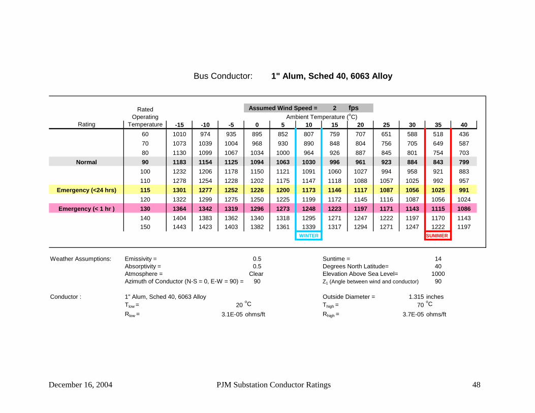
December 16, 2004 PJM Substation Conductor Ratings 48
Bus Conductor: 1" Alum, Sched 40, 6063 Alloy
2 fps
Rating -15 -10 -5 0 5 10 15 20 25 30 35 4060 1010 974 935 895 852 807 759 707 651 588 518 43670 1073 1039 1004 968 930 890 848 804 756 705 649 58780 1130 1099 1067 1034 1000 964 926 887 845 801 754 703
Normal 90 1183 1154 1125 1094 1063 1030 996 961 923 884 843 799100 1232 1206 1178 1150 1121 1091 1060 1027 994 958 921 883110 1278 1254 1228 1202 1175 1147 1118 1088 1057 1025 992 957
Emergency (<24 hrs) 115 1301 1277 1252 1226 1200 1173 1146 1117 1087 1056 1025 991120 1322 1299 1275 1250 1225 1199 1172 1145 1116 1087 1056 1024
Emergency (< 1 hr ) 130 1364 1342 1319 1296 1273 1248 1223 1197 1171 1143 1115 1086140 1404 1383 1362 1340 1318 1295 1271 1247 1222 1197 1170 1143150 1443 1423 1403 1382 1361 1339 1317 1294 1271 1247 1222 1197
WINTER SUMMER
Weather Assumptions: Emissivity = 0.5 Suntime = 14Absorptivity = 0.5 Degrees North Latitude= 40Atmosphere = Clear Elevation Above Sea Level= 1000Azimuth of Conductor (N-S = 0, E-W = 90) = 90 Z1 (Angle between wind and conductor) 90
Conductor : 1" Alum, Sched 40, 6063 Alloy Outside Diameter = 1.315 inchesTlow = 20
oC Thigh = 70oC
Rlow = 3.1E-05 ohms/ft Rhigh = 3.7E-05 ohms/ft
Ambient Temperature (oC)Assumed Wind Speed =Rated
Operating Temperature

December 16, 2004 PJM Substation Conductor Ratings 49
Bus Conductor: 1-1/2" Alum, Sched 40, 6063 Alloy
2 fps
Rating -15 -10 -5 0 5 10 15 20 25 30 35 4060 1424 1371 1315 1257 1196 1132 1062 988 906 815 712 58970 1513 1466 1416 1365 1310 1254 1193 1129 1061 987 906 81680 1597 1553 1508 1461 1412 1361 1308 1251 1191 1128 1060 987
Normal 90 1675 1634 1593 1549 1505 1458 1410 1359 1306 1250 1191 1128100 1747 1710 1671 1631 1590 1547 1503 1457 1409 1358 1306 1250110 1815 1780 1744 1707 1669 1629 1589 1546 1502 1457 1409 1359
Emergency (<24 hrs) 115 1848 1814 1779 1744 1707 1669 1629 1588 1546 1503 1457 1409120 1880 1847 1814 1779 1743 1706 1668 1629 1589 1547 1503 1458
Emergency (< 1 hr ) 130 1942 1911 1879 1847 1813 1779 1744 1707 1669 1630 1590 1548140 2002 1972 1942 1912 1880 1848 1815 1780 1745 1709 1672 1633150 2059 2031 2003 1974 1944 1914 1882 1850 1817 1783 1748 1712
WINTER SUMMER
Weather Assumptions: Emissivity = 0.5 Suntime = 14Absorptivity = 0.5 Degrees North Latitude= 40Atmosphere = Clear Elevation Above Sea Level= 1000Azimuth of Conductor (N-S = 0, E-W = 90) = 90 Z1 (Angle between wind and conductor) 90
Conductor : 1-1/2" Alum, Sched 40, 6063 Alloy Outside Diameter = 1.9 inchesTlow = 20
oC Thigh = 70oC
Rlow = 1.9E-05 ohms/ft Rhigh = 2.3E-05 ohms/ft
Ambient Temperature (oC)Assumed Wind Speed =Rated
Operating Temperature

December 16, 2004 PJM Substation Conductor Ratings 50
Bus Conductor: 2" Alum, Sched 40, 6063 Alloy
2 fps
Rating -15 -10 -5 0 5 10 15 20 25 30 35 4060 1771 1704 1635 1562 1484 1402 1314 1219 1115 1000 868 71070 1885 1824 1762 1696 1627 1555 1479 1398 1311 1217 1114 100080 1989 1934 1876 1817 1755 1690 1622 1551 1475 1395 1309 1216
Normal 90 2085 2034 1981 1927 1870 1811 1750 1686 1619 1548 1473 1394100 2175 2128 2079 2028 1976 1922 1866 1808 1747 1684 1617 1548110 2260 2215 2170 2123 2074 2024 1973 1919 1864 1807 1748 1685
Emergency (<24 hrs) 115 2301 2258 2213 2168 2121 2073 2023 1972 1919 1865 1808 1749120 2340 2299 2256 2212 2167 2120 2072 2023 1973 1921 1867 1810
Emergency (< 1 hr ) 130 2417 2378 2337 2296 2254 2211 2167 2122 2075 2027 1977 1925140 2491 2454 2416 2377 2338 2299 2258 2215 2172 2127 2081 2033150 2562 2527 2492 2457 2420 2382 2344 2304 2263 2221 2178 2133
WINTER SUMMER
Weather Assumptions: Emissivity = 0.5 Suntime = 14Absorptivity = 0.5 Degrees North Latitude= 40Atmosphere = Clear Elevation Above Sea Level= 1000Azimuth of Conductor (N-S = 0, E-W = 90) = 90 Z1 (Angle between wind and conductor) 90
Conductor : 2" Alum, Sched 40, 6063 Alloy Outside Diameter = 2.375 inchesTlow = 20
oC Thigh = 70oC
Rlow = 1.4E-05 ohms/ft Rhigh = 1.7E-05 ohms/ft
Ambient Temperature (oC)Assumed Wind Speed =Rated
Operating Temperature

December 16, 2004 PJM Substation Conductor Ratings 51
Bus Conductor: 2-1/2" Alum, Sched 40, 6063 Alloy
2 fps
Rating -15 -10 -5 0 5 10 15 20 25 30 35 4060 2370 2280 2186 2088 1984 1873 1754 1625 1484 1326 1145 92870 2525 2444 2359 2271 2179 2081 1978 1869 1751 1624 1484 132980 2667 2593 2516 2436 2352 2265 2174 2077 1976 1867 1751 1625
Normal 90 2799 2730 2659 2586 2510 2431 2348 2262 2171 2076 1975 1868100 2922 2858 2792 2724 2654 2582 2507 2428 2347 2261 2172 2077110 3038 2978 2917 2854 2789 2722 2653 2581 2506 2429 2348 2263
Emergency (<24 hrs) 115 3094 3036 2977 2916 2853 2789 2722 2653 2582 2507 2430 2349120 3148 3092 3035 2976 2915 2853 2789 2723 2654 2583 2509 2432
Emergency (< 1 hr ) 130 3253 3201 3147 3092 3035 2977 2917 2855 2791 2726 2658 2587140 3355 3305 3254 3202 3149 3094 3038 2980 2921 2860 2797 2731150 3452 3405 3357 3308 3258 3207 3154 3100 3044 2987 2928 2867
WINTER SUMMER
Weather Assumptions: Emissivity = 0.5 Suntime = 14Absorptivity = 0.5 Degrees North Latitude= 40Atmosphere = Clear Elevation Above Sea Level= 1000Azimuth of Conductor (N-S = 0, E-W = 90) = 90 Z1 (Angle between wind and conductor) 90
Conductor : 2-1/2" Alum, Sched 40, 6063 Alloy Outside Diameter = 2.875 inchesTlow = 20
oC Thigh = 70oC
Rlow = 9E-06 ohms/ft Rhigh = 1.1E-05 ohms/ft
Ambient Temperature (oC)Assumed Wind Speed =Rated
Operating Temperature

December 16, 2004 PJM Substation Conductor Ratings 52
Bus Conductor: 3" Alum, Sched 40, 6063 Alloy
2 fps
Rating -15 -10 -5 0 5 10 15 20 25 30 35 4060 2885 2775 2660 2539 2411 2275 2128 1969 1795 1599 1373 109970 3077 2978 2875 2767 2653 2534 2407 2272 2128 1970 1798 160580 3254 3163 3069 2971 2869 2762 2650 2532 2406 2273 2130 1974
Normal 90 3417 3333 3247 3157 3064 2967 2866 2761 2650 2533 2409 2277100 3570 3492 3412 3329 3244 3155 3063 2968 2868 2763 2653 2537110 3715 3642 3567 3491 3411 3329 3245 3157 3066 2971 2872 2768
Emergency (<24 hrs) 115 3784 3714 3642 3567 3491 3412 3331 3247 3159 3068 2974 2875120 3852 3784 3714 3642 3568 3492 3414 3333 3249 3162 3072 2977
Emergency (< 1 hr ) 130 3983 3919 3854 3786 3717 3646 3573 3498 3420 3340 3257 3170140 4109 4049 3987 3924 3859 3793 3724 3654 3582 3507 3430 3350150 4232 4174 4116 4056 3995 3933 3869 3803 3735 3665 3593 3519
WINTER SUMMER
Weather Assumptions: Emissivity = 0.5 Suntime = 14Absorptivity = 0.5 Degrees North Latitude= 40Atmosphere = Clear Elevation Above Sea Level= 1000Azimuth of Conductor (N-S = 0, E-W = 90) = 90 Z1 (Angle between wind and conductor) 90
Conductor : 3" Alum, Sched 40, 6063 Alloy Outside Diameter = 3.5 inchesTlow = 20
oC Thigh = 70oC
Rlow = 6.9E-06 ohms/ft Rhigh = 8.1E-06 ohms/ft
Ambient Temperature (oC)Assumed Wind Speed =Rated
Operating Temperature
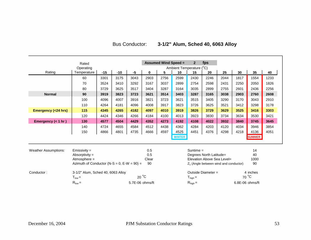
December 16, 2004 PJM Substation Conductor Ratings 53
Bus Conductor: 3-1/2" Alum, Sched 40, 6063 Alloy
2 fps
Rating -15 -10 -5 0 5 10 15 20 25 30 35 4060 3301 3175 3043 2903 2756 2599 2430 2246 2044 1817 1554 123370 3524 3410 3292 3167 3037 2899 2754 2598 2431 2250 2050 182680 3729 3625 3517 3404 3287 3164 3035 2899 2755 2601 2436 2256
Normal 90 3919 3823 3723 3621 3514 3403 3287 3165 3038 2903 2760 2608100 4096 4007 3916 3821 3723 3621 3515 3405 3290 3170 3043 2910110 4264 4181 4096 4008 3917 3823 3726 3625 3521 3412 3298 3178
Emergency (<24 hrs) 115 4345 4265 4182 4097 4010 3919 3826 3729 3629 3525 3416 3303120 4424 4346 4266 4184 4100 4013 3923 3830 3734 3634 3530 3421
Emergency (< 1 hr ) 130 4577 4504 4429 4352 4273 4192 4108 4022 3932 3840 3745 3645140 4724 4655 4584 4512 4438 4362 4284 4203 4120 4034 3946 3854150 4866 4801 4735 4666 4597 4525 4451 4376 4298 4218 4136 4051
WINTER SUMMER
Weather Assumptions: Emissivity = 0.5 Suntime = 14Absorptivity = 0.5 Degrees North Latitude= 40Atmosphere = Clear Elevation Above Sea Level= 1000Azimuth of Conductor (N-S = 0, E-W = 90) = 90 Z1 (Angle between wind and conductor) 90
Conductor : 3-1/2" Alum, Sched 40, 6063 Alloy Outside Diameter = 4 inchesTlow = 20
oC Thigh = 70oC
Rlow = 5.7E-06 ohms/ft Rhigh = 6.8E-06 ohms/ft
Ambient Temperature (oC)Assumed Wind Speed =Rated
Operating Temperature

December 16, 2004 PJM Substation Conductor Ratings 54
Bus Conductor: 4" Alum, Sched 40, 6063 Alloy
2 fps
Rating -15 -10 -5 0 5 10 15 20 25 30 35 4060 3729 3586 3437 3278 3111 2932 2739 2530 2299 2040 1738 136770 3985 3856 3721 3580 3432 3276 3110 2934 2743 2536 2308 205280 4219 4101 3979 3851 3718 3579 3433 3278 3114 2939 2751 2546
Normal 90 4436 4327 4215 4099 3978 3852 3720 3582 3437 3284 3122 2948100 4639 4539 4435 4327 4216 4101 3981 3857 3726 3590 3446 3294110 4831 4738 4641 4541 4439 4333 4223 4109 3990 3866 3737 3601
Emergency (<24 hrs) 115 4924 4833 4740 4644 4545 4443 4337 4227 4114 3996 3872 3744120 5014 4926 4836 4743 4648 4549 4448 4342 4233 4120 4002 3880
Emergency (< 1 hr ) 130 5189 5107 5022 4935 4846 4754 4660 4562 4461 4357 4248 4136140 5358 5280 5201 5119 5035 4949 4861 4770 4676 4579 4479 4375150 5522 5448 5373 5296 5217 5136 5053 4968 4880 4790 4696 4600
WINTER SUMMER
Weather Assumptions: Emissivity = 0.5 Suntime = 14Absorptivity = 0.5 Degrees North Latitude= 40Atmosphere = Clear Elevation Above Sea Level= 1000Azimuth of Conductor (N-S = 0, E-W = 90) = 90 Z1 (Angle between wind and conductor) 90
Conductor : 4" Alum, Sched 40, 6063 Alloy Outside Diameter = 4.5 inchesTlow = 20
oC Thigh = 70oC
Rlow = 4.8E-06 ohms/ft Rhigh = 5.7E-06 ohms/ft
Ambient Temperature (oC)Assumed Wind Speed =Rated
Operating Temperature

December 16, 2004 PJM Substation Conductor Ratings 55
Bus Conductor: 4-1/2" Alum, Sched 40, 6063 Alloy
2 fps
Rating -15 -10 -5 0 5 10 15 20 25 30 35 4060 4158 3998 3830 3653 3465 3265 3048 2813 2553 2260 1919 149670 4446 4302 4151 3993 3828 3653 3467 3269 3055 2823 2566 227780 4710 4578 4441 4299 4150 3994 3831 3657 3474 3277 3066 2836
Normal 90 4955 4833 4708 4578 4443 4302 4155 4001 3838 3667 3485 3290100 5184 5072 4956 4836 4712 4583 4450 4310 4164 4011 3850 3680110 5401 5296 5189 5078 4963 4844 4722 4594 4461 4323 4178 4026
Emergency (<24 hrs) 115 5506 5404 5300 5193 5083 4969 4851 4728 4601 4469 4331 4187120 5608 5510 5409 5306 5199 5089 4976 4858 4736 4610 4478 4340
Emergency (< 1 hr ) 130 5806 5714 5619 5523 5423 5321 5215 5106 4993 4876 4755 4630140 5997 5910 5821 5730 5637 5541 5442 5341 5236 5127 5015 4899150 6181 6100 6016 5930 5842 5752 5660 5564 5466 5365 5261 5154
WINTER SUMMER
Weather Assumptions: Emissivity = 0.5 Suntime = 14Absorptivity = 0.5 Degrees North Latitude= 40Atmosphere = Clear Elevation Above Sea Level= 1000Azimuth of Conductor (N-S = 0, E-W = 90) = 90 Z1 (Angle between wind and conductor) 90
Conductor : 4-1/2" Alum, Sched 40, 6063 Alloy Outside Diameter = 5 inchesTlow = 20
oC Thigh = 70oC
Rlow = 4.2E-06 ohms/ft Rhigh = 4.9E-06 ohms/ft
Ambient Temperature (oC)Assumed Wind Speed =Rated
Operating Temperature

December 16, 2004 PJM Substation Conductor Ratings 56
Bus Conductor: 5" Alum, Sched 40, 6063 Alloy
2 fps
Rating -15 -10 -5 0 5 10 15 20 25 30 35 4060 4647 4468 4279 4080 3869 3643 3400 3135 2842 2510 2122 163970 4973 4811 4642 4465 4279 4083 3874 3651 3410 3148 2858 253180 5271 5124 4971 4811 4644 4469 4285 4091 3884 3663 3425 3166
Normal 90 5548 5413 5272 5127 4975 4817 4652 4479 4297 4104 3899 3680100 5808 5683 5553 5419 5280 5136 4986 4829 4666 4494 4313 4122110 6054 5937 5817 5692 5564 5431 5294 5151 5002 4847 4684 4514
Emergency (<24 hrs) 115 6173 6060 5943 5823 5700 5572 5440 5303 5160 5012 4857 4696120 6288 6179 6067 5951 5832 5709 5581 5450 5313 5171 5024 4869
Emergency (< 1 hr ) 130 6513 6410 6305 6197 6085 5971 5852 5730 5604 5473 5338 5197140 6730 6633 6534 6432 6328 6221 6110 5996 5879 5758 5632 5502150 6940 6848 6755 6659 6561 6460 6357 6250 6141 6027 5911 5790
WINTER SUMMER
Weather Assumptions: Emissivity = 0.5 Suntime = 14Absorptivity = 0.5 Degrees North Latitude= 40Atmosphere = Clear Elevation Above Sea Level= 1000Azimuth of Conductor (N-S = 0, E-W = 90) = 90 Z1 (Angle between wind and conductor) 90
Conductor : 5" Alum, Sched 40, 6063 Alloy Outside Diameter = 5.563 inchesTlow = 20
oC Thigh = 70oC
Rlow = 3.6E-06 ohms/ft Rhigh = 4.2E-06 ohms/ft
Ambient Temperature (oC)Assumed Wind Speed =Rated
Operating Temperature

December 16, 2004 PJM Substation Conductor Ratings 57
Bus Conductor: 6" Alum, Sched 40, 6063 Alloy
2 fps
Rating -15 -10 -5 0 5 10 15 20 25 30 35 4060 5599 5382 5154 4912 4655 4380 4083 3759 3399 2991 2511 190470 6000 5804 5600 5385 5159 4921 4667 4395 4101 3781 3425 302380 6367 6188 6003 5810 5608 5396 5172 4936 4684 4415 4125 3807
Normal 90 6707 6544 6374 6198 6014 5823 5623 5413 5192 4957 4708 4441100 7027 6876 6719 6557 6389 6215 6033 5843 5645 5437 5217 4984110 7330 7189 7043 6893 6738 6578 6412 6239 6058 5870 5673 5466
Emergency (<24 hrs) 115 7476 7339 7199 7055 6905 6751 6591 6425 6253 6073 5886 5689120 7618 7487 7351 7211 7068 6919 6765 6606 6441 6269 6090 5903
Emergency (< 1 hr ) 130 7895 7772 7645 7514 7380 7242 7099 6952 6799 6641 6477 6306140 8163 8046 7927 7805 7679 7550 7416 7279 7137 6991 6839 6682150 8422 8312 8200 8085 7966 7845 7720 7592 7459 7323 7182 7036
WINTER SUMMER
Weather Assumptions: Emissivity = 0.5 Suntime = 14Absorptivity = 0.5 Degrees North Latitude= 40Atmosphere = Clear Elevation Above Sea Level= 1000Azimuth of Conductor (N-S = 0, E-W = 90) = 90 Z1 (Angle between wind and conductor) 90
Conductor : 6" Alum, Sched 40, 6063 Alloy Outside Diameter = 6.625 inchesTlow = 20
oC Thigh = 70oC
Rlow = 2.8E-06 ohms/ft Rhigh = 3.3E-06 ohms/ft
Ambient Temperature (oC)Assumed Wind Speed =Rated
Operating Temperature

December 16, 2004 PJM Substation Conductor Ratings 58
Bus Conductor: 1" Alum, Sched 80, 6063 Alloy
2 fps
Rating -15 -10 -5 0 5 10 15 20 25 30 35 4060 1149 1107 1064 1018 969 918 863 804 740 669 589 49670 1220 1182 1142 1101 1058 1013 965 914 860 802 738 66880 1285 1250 1214 1176 1137 1096 1054 1009 961 911 858 800
Normal 90 1345 1313 1279 1245 1209 1172 1133 1093 1050 1006 959 909100 1401 1371 1340 1308 1275 1241 1205 1168 1130 1090 1048 1004110 1454 1426 1397 1367 1336 1304 1272 1238 1203 1166 1128 1088
Emergency (<24 hrs) 115 1479 1452 1424 1395 1365 1335 1303 1270 1237 1202 1165 1127120 1504 1477 1450 1422 1393 1364 1333 1302 1269 1236 1201 1165
Emergency (< 1 hr ) 130 1552 1526 1501 1474 1448 1420 1391 1362 1332 1301 1268 1235140 1597 1573 1549 1524 1499 1473 1446 1419 1390 1361 1331 1300150 1641 1618 1595 1572 1548 1523 1498 1472 1446 1418 1390 1361
WINTER SUMMER
Weather Assumptions: Emissivity = 0.5 Suntime = 14Absorptivity = 0.5 Degrees North Latitude= 40Atmosphere = Clear Elevation Above Sea Level= 1000Azimuth of Conductor (N-S = 0, E-W = 90) = 90 Z1 (Angle between wind and conductor) 90
Conductor : 1" Alum, Sched 80, 6063 Alloy Outside Diameter = 1.315 inchesTlow = 20
oC Thigh = 70oC
Rlow = 2.4E-05 ohms/ft Rhigh = 2.8E-05 ohms/ft
Ambient Temperature (oC)Assumed Wind Speed =Rated
Operating Temperature
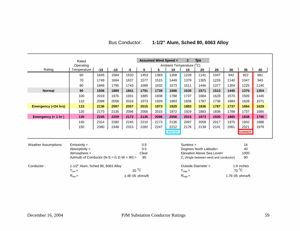
December 16, 2004 PJM Substation Conductor Ratings 59
Bus Conductor: 1-1/2" Alum, Sched 80, 6063 Alloy
2 fps
Rating -15 -10 -5 0 5 10 15 20 25 30 35 4060 1645 1584 1520 1453 1383 1308 1228 1141 1047 942 822 68170 1749 1694 1637 1577 1515 1449 1379 1305 1226 1140 1047 94380 1846 1795 1743 1689 1632 1573 1511 1446 1377 1304 1225 1140
Normal 90 1936 1889 1841 1791 1739 1686 1630 1571 1510 1445 1376 1304100 2019 1976 1931 1885 1838 1788 1737 1684 1628 1570 1509 1445110 2098 2058 2016 1973 1929 1883 1836 1787 1736 1684 1628 1571
Emergency (<24 hrs) 115 2136 2097 2057 2015 1973 1929 1883 1836 1787 1737 1684 1629120 2173 2135 2096 2056 2015 1972 1929 1883 1836 1788 1737 1685
Emergency (< 1 hr ) 130 2245 2209 2172 2135 2096 2056 2015 1973 1930 1885 1838 1790140 2314 2280 2245 2210 2173 2136 2097 2058 2017 1975 1932 1888150 2380 2348 2315 2282 2247 2212 2176 2139 2101 2061 2021 1979
WINTER SUMMER
Weather Assumptions: Emissivity = 0.5 Suntime = 14Absorptivity = 0.5 Degrees North Latitude= 40Atmosphere = Clear Elevation Above Sea Level= 1000Azimuth of Conductor (N-S = 0, E-W = 90) = 90 Z1 (Angle between wind and conductor) 90
Conductor : 1-1/2" Alum, Sched 80, 6063 Alloy Outside Diameter = 1.9 inchesTlow = 20
oC Thigh = 70oC
Rlow = 1.4E-05 ohms/ft Rhigh = 1.7E-05 ohms/ft
Ambient Temperature (oC)Assumed Wind Speed =Rated
Operating Temperature

December 16, 2004 PJM Substation Conductor Ratings 60
Bus Conductor: 2" Alum, Sched 80, 6063 Alloy
2 fps
Rating -15 -10 -5 0 5 10 15 20 25 30 35 4060 2072 1994 1913 1827 1737 1640 1538 1426 1305 1170 1015 83070 2204 2133 2060 1983 1903 1819 1729 1634 1533 1423 1303 116980 2325 2260 2193 2124 2051 1975 1896 1813 1724 1631 1530 1422
Normal 90 2437 2377 2315 2251 2185 2116 2045 1970 1892 1809 1722 1629100 2541 2485 2428 2369 2308 2245 2180 2112 2041 1967 1889 1808110 2639 2587 2534 2479 2422 2364 2304 2241 2177 2110 2041 1968
Emergency (<24 hrs) 115 2686 2636 2584 2531 2477 2421 2363 2303 2241 2178 2112 2042120 2732 2684 2634 2582 2529 2475 2419 2362 2304 2243 2179 2113
Emergency (< 1 hr ) 130 2821 2775 2728 2680 2631 2581 2529 2477 2422 2366 2308 2247140 2906 2863 2819 2774 2729 2682 2634 2585 2534 2482 2428 2372150 2988 2948 2907 2866 2823 2779 2734 2688 2640 2591 2541 2489
WINTER SUMMER
Weather Assumptions: Emissivity = 0.5 Suntime = 14Absorptivity = 0.5 Degrees North Latitude= 40Atmosphere = Clear Elevation Above Sea Level= 1000Azimuth of Conductor (N-S = 0, E-W = 90) = 90 Z1 (Angle between wind and conductor) 90
Conductor : 2" Alum, Sched 80, 6063 Alloy Outside Diameter = 2.375 inchesTlow = 20
oC Thigh = 70oC
Rlow = 1E-05 ohms/ft Rhigh = 1.2E-05 ohms/ft
Ambient Temperature (oC)Assumed Wind Speed =Rated
Operating Temperature

December 16, 2004 PJM Substation Conductor Ratings 61
Bus Conductor: 2-1/2" Alum, Sched 80, 6063 Alloy
2 fps
Rating -15 -10 -5 0 5 10 15 20 25 30 35 4060 2719 2616 2509 2395 2276 2149 2012 1864 1702 1522 1314 106470 2896 2802 2706 2604 2498 2387 2269 2143 2008 1862 1702 152480 3057 2972 2884 2792 2696 2596 2491 2381 2264 2140 2007 1862
Normal 90 3207 3128 3047 2963 2875 2785 2690 2591 2488 2379 2263 2140100 3346 3273 3198 3120 3040 2957 2871 2781 2688 2590 2487 2379110 3478 3409 3339 3267 3193 3116 3037 2955 2869 2780 2688 2591
Emergency (<24 hrs) 115 3541 3475 3407 3337 3266 3192 3115 3036 2955 2870 2781 2689120 3602 3538 3473 3405 3336 3265 3191 3115 3037 2955 2871 2783
Emergency (< 1 hr ) 130 3722 3661 3600 3537 3472 3405 3337 3266 3193 3118 3040 2959140 3836 3779 3721 3662 3601 3538 3474 3408 3340 3270 3198 3123150 3946 3893 3838 3782 3724 3665 3605 3543 3480 3414 3347 3278
WINTER SUMMER
Weather Assumptions: Emissivity = 0.5 Suntime = 14Absorptivity = 0.5 Degrees North Latitude= 40Atmosphere = Clear Elevation Above Sea Level= 1000Azimuth of Conductor (N-S = 0, E-W = 90) = 90 Z1 (Angle between wind and conductor) 90
Conductor : 2-1/2" Alum, Sched 80, 6063 Alloy Outside Diameter = 2.875 inchesTlow = 20
oC Thigh = 70oC
Rlow = 6.8E-06 ohms/ft Rhigh = 8.1E-06 ohms/ft
Ambient Temperature (oC)Assumed Wind Speed =Rated
Operating Temperature
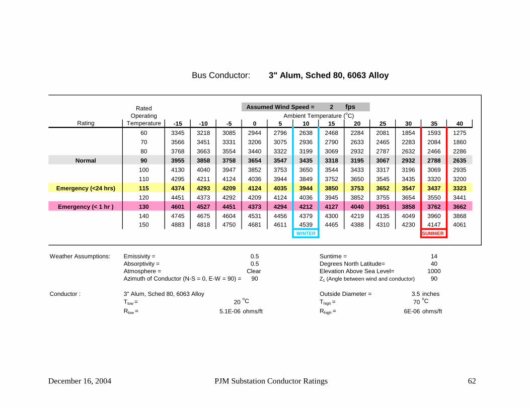
December 16, 2004 PJM Substation Conductor Ratings 62
Bus Conductor: 3" Alum, Sched 80, 6063 Alloy
2 fps
Rating -15 -10 -5 0 5 10 15 20 25 30 35 4060 3345 3218 3085 2944 2796 2638 2468 2284 2081 1854 1593 127570 3566 3451 3331 3206 3075 2936 2790 2633 2465 2283 2084 186080 3768 3663 3554 3440 3322 3199 3069 2932 2787 2632 2466 2286
Normal 90 3955 3858 3758 3654 3547 3435 3318 3195 3067 2932 2788 2635100 4130 4040 3947 3852 3753 3650 3544 3433 3317 3196 3069 2935110 4295 4211 4124 4036 3944 3849 3752 3650 3545 3435 3320 3200
Emergency (<24 hrs) 115 4374 4293 4209 4124 4035 3944 3850 3753 3652 3547 3437 3323120 4451 4373 4292 4209 4124 4036 3945 3852 3755 3654 3550 3441
Emergency (< 1 hr ) 130 4601 4527 4451 4373 4294 4212 4127 4040 3951 3858 3762 3662140 4745 4675 4604 4531 4456 4379 4300 4219 4135 4049 3960 3868150 4883 4818 4750 4681 4611 4539 4465 4388 4310 4230 4147 4061
WINTER SUMMER
Weather Assumptions: Emissivity = 0.5 Suntime = 14Absorptivity = 0.5 Degrees North Latitude= 40Atmosphere = Clear Elevation Above Sea Level= 1000Azimuth of Conductor (N-S = 0, E-W = 90) = 90 Z1 (Angle between wind and conductor) 90
Conductor : 3" Alum, Sched 80, 6063 Alloy Outside Diameter = 3.5 inchesTlow = 20
oC Thigh = 70oC
Rlow = 5.1E-06 ohms/ft Rhigh = 6E-06 ohms/ft
Ambient Temperature (oC)Assumed Wind Speed =Rated
Operating Temperature

December 16, 2004 PJM Substation Conductor Ratings 63
Bus Conductor: 3-1/2" Alum, Sched 80, 6063 Alloy
2 fps
Rating -15 -10 -5 0 5 10 15 20 25 30 35 4060 3851 3704 3550 3388 3215 3032 2835 2621 2385 2120 1813 143870 4108 3975 3837 3692 3540 3380 3210 3029 2834 2623 2390 212880 4343 4222 4096 3965 3829 3686 3536 3377 3209 3030 2837 2628
Normal 90 4561 4449 4334 4214 4090 3960 3825 3684 3535 3379 3212 3035100 4764 4661 4554 4444 4330 4211 4088 3960 3827 3687 3540 3384110 4956 4860 4760 4658 4553 4444 4331 4214 4092 3965 3833 3694
Emergency (<24 hrs) 115 5048 4955 4859 4760 4659 4554 4445 4333 4217 4095 3969 3837120 5139 5048 4955 4860 4762 4661 4556 4448 4337 4221 4100 3974
Emergency (< 1 hr ) 130 5313 5228 5141 5052 4960 4866 4768 4668 4565 4458 4347 4232140 5481 5401 5319 5235 5149 5060 4970 4876 4780 4680 4578 4471150 5643 5567 5490 5411 5330 5247 5161 5074 4984 4891 4796 4697
WINTER SUMMER
Weather Assumptions: Emissivity = 0.5 Suntime = 14Absorptivity = 0.5 Degrees North Latitude= 40Atmosphere = Clear Elevation Above Sea Level= 1000Azimuth of Conductor (N-S = 0, E-W = 90) = 90 Z1 (Angle between wind and conductor) 90
Conductor : 3-1/2" Alum, Sched 80, 6063 Alloy Outside Diameter = 4 inchesTlow = 20
oC Thigh = 70oC
Rlow = 4.2E-06 ohms/ft Rhigh = 5E-06 ohms/ft
Ambient Temperature (oC)Assumed Wind Speed =Rated
Operating Temperature

December 16, 2004 PJM Substation Conductor Ratings 64
Bus Conductor: 4" Alum, Sched 80, 6063 Alloy
2 fps
Rating -15 -10 -5 0 5 10 15 20 25 30 35 4060 4419 4250 4073 3885 3687 3475 3246 2998 2725 2417 2060 161970 4728 4575 4415 4248 4072 3887 3691 3481 3255 3010 2739 243580 5012 4871 4726 4575 4417 4251 4078 3894 3699 3492 3268 3025
Normal 90 5275 5146 5012 4874 4730 4580 4424 4260 4088 3906 3713 3506100 5523 5403 5279 5152 5019 4882 4740 4591 4436 4274 4102 3922110 5757 5645 5530 5412 5289 5163 5032 4896 4754 4607 4453 4291
Emergency (<24 hrs) 115 5870 5762 5651 5536 5418 5296 5170 5040 4905 4764 4617 4463120 5981 5876 5768 5658 5544 5426 5305 5179 5049 4914 4774 4627
Emergency (< 1 hr ) 130 6195 6097 5996 5892 5785 5676 5563 5446 5326 5201 5072 4938140 6402 6309 6214 6116 6016 5914 5808 5699 5587 5471 5351 5227150 6603 6515 6425 6333 6239 6142 6043 5940 5835 5727 5616 5501
WINTER SUMMER
Weather Assumptions: Emissivity = 0.5 Suntime = 14Absorptivity = 0.5 Degrees North Latitude= 40Atmosphere = Clear Elevation Above Sea Level= 1000Azimuth of Conductor (N-S = 0, E-W = 90) = 90 Z1 (Angle between wind and conductor) 90
Conductor : 4" Alum, Sched 80, 6063 Alloy Outside Diameter = 4.5 inchesTlow = 20
oC Thigh = 80oC
Rlow = 3.5E-06 ohms/ft Rhigh = 4.2E-06 ohms/ft
Ambient Temperature (oC)Assumed Wind Speed =Rated
Operating Temperature

December 16, 2004 PJM Substation Conductor Ratings 65
Bus Conductor: 4-1/2" Alum, Sched 80, 6063 Alloy
2 fps
Rating -15 -10 -5 0 5 10 15 20 25 30 35 4060 4895 4707 4510 4301 4080 3844 3589 3312 3006 2661 2259 176170 5227 5058 4881 4695 4501 4295 4077 3843 3592 3319 3017 267780 5530 5376 5215 5048 4873 4690 4498 4295 4079 3848 3600 3330
Normal 90 5811 5669 5522 5369 5211 5045 4873 4692 4502 4300 4087 3859100 6073 5942 5806 5666 5520 5369 5213 5049 4878 4699 4511 4311110 6321 6198 6072 5942 5808 5669 5525 5376 5221 5059 4890 4712
Emergency (<24 hrs) 115 6440 6321 6199 6074 5945 5811 5673 5530 5382 5227 5066 4897120 6556 6441 6324 6203 6078 5949 5817 5679 5537 5389 5235 5074
Emergency (< 1 hr ) 130 6781 6673 6563 6450 6334 6214 6091 5963 5832 5695 5554 5407140 6997 6896 6792 6686 6577 6465 6350 6232 6109 5983 5852 5717150 7207 7111 7014 6914 6811 6706 6598 6487 6373 6255 6134 6008
WINTER SUMMER
Weather Assumptions: Emissivity = 0.5 Suntime = 14Absorptivity = 0.5 Degrees North Latitude= 40Atmosphere = Clear Elevation Above Sea Level= 1000Azimuth of Conductor (N-S = 0, E-W = 90) = 90 Z1 (Angle between wind and conductor) 90
Conductor : 4-1/2" Alum, Sched 80, 6063 Alloy Outside Diameter = 5 inchesTlow = 20
oC Thigh = 70oC
Rlow = 3E-06 ohms/ft Rhigh = 3.6E-06 ohms/ft
Ambient Temperature (oC)Assumed Wind Speed =Rated
Operating Temperature

December 16, 2004 PJM Substation Conductor Ratings 66
Bus Conductor: 5" Alum, Sched 80, 6063 Alloy
2 fps
Rating -15 -10 -5 0 5 10 15 20 25 30 35 4060 5492 5281 5058 4823 4573 4307 4019 3705 3359 2967 2508 193770 5867 5676 5477 5269 5049 4817 4571 4308 4024 3715 3373 298780 6209 6035 5855 5667 5470 5265 5048 4819 4575 4315 4035 3729
Normal 90 6525 6366 6201 6029 5851 5665 5471 5268 5053 4827 4586 4328100 6821 6674 6521 6364 6201 6031 5855 5671 5479 5278 5065 4841110 7100 6963 6821 6676 6525 6369 6208 6040 5866 5684 5493 5293
Emergency (<24 hrs) 115 7234 7101 6965 6825 6680 6530 6375 6215 6048 5874 5693 5503120 7365 7237 7105 6969 6830 6686 6537 6383 6223 6056 5883 5703
Emergency (< 1 hr ) 130 7619 7498 7375 7248 7118 6984 6846 6703 6555 6402 6244 6079140 7863 7750 7634 7515 7393 7268 7139 7006 6869 6727 6580 6429150 8099 7992 7883 7771 7657 7539 7418 7294 7166 7034 6898 6757
WINTER SUMMER
Weather Assumptions: Emissivity = 0.5 Suntime = 14Absorptivity = 0.5 Degrees North Latitude= 40Atmosphere = Clear Elevation Above Sea Level= 1000Azimuth of Conductor (N-S = 0, E-W = 90) = 90 Z1 (Angle between wind and conductor) 90
Conductor : 5" Alum, Sched 80, 6063 Alloy Outside Diameter = 5.563 inchesTlow = 20
oC Thigh = 70oC
Rlow = 2.5E-06 ohms/ft Rhigh = 3E-06 ohms/ft
Ambient Temperature (oC)Assumed Wind Speed =Rated
Operating Temperature

December 16, 2004 PJM Substation Conductor Ratings 67
Bus Conductor: 6" Alum, Sched 80, 6063 Alloy
2 fps
Rating -15 -10 -5 0 5 10 15 20 25 30 35 4060 6762 6500 6224 5932 5622 5290 4931 4539 4105 3612 3032 230070 7222 6986 6740 6482 6210 5923 5617 5290 4936 4551 4123 363980 7640 7426 7203 6971 6729 6474 6206 5923 5621 5298 4949 4569
Normal 90 8025 7829 7626 7416 7196 6967 6728 6476 6212 5931 5633 5314100 8385 8204 8017 7824 7624 7416 7199 6973 6736 6487 6225 5948110 8724 8556 8383 8205 8020 7829 7631 7425 7211 6987 6752 6506
Emergency (<24 hrs) 115 8887 8725 8558 8386 8209 8025 7835 7638 7433 7220 6997 6763120 9046 8889 8728 8563 8392 8215 8033 7844 7648 7444 7231 7009
Emergency (< 1 hr ) 130 9353 9207 9057 8902 8743 8579 8410 8235 8055 7867 7673 7470140 9649 9512 9371 9226 9077 8925 8767 8605 8437 8264 8085 7899150 9936 9806 9674 9538 9398 9255 9108 8956 8800 8639 8473 8301
WINTER SUMMER
Weather Assumptions: Emissivity = 0.5 Suntime = 14Absorptivity = 0.5 Degrees North Latitude= 40Atmosphere = Clear Elevation Above Sea Level= 1000Azimuth of Conductor (N-S = 0, E-W = 90) = 90 Z1 (Angle between wind and conductor) 90
Conductor : 6" Alum, Sched 80, 6063 Alloy Outside Diameter = 6.625 inchesTlow = 20
oC Thigh = 70oC
Rlow = 1.8E-06 ohms/ft Rhigh = 2.2E-06 ohms/ft
Ambient Temperature (oC)Assumed Wind Speed =Rated
Operating Temperature

December 16, 2004 PJM Substation Conductor Ratings 68
Bus Conductor: 3/4" Copper, Schedule 40, 98% ICAS
2 fps
Rating -15 -10 -5 0 5 10 15 20 25 30 35 4060 1081 1041 998 954 906 855 801 742 677 604 519 41770 1154 1117 1079 1039 997 953 906 856 802 743 679 60780 1220 1187 1152 1116 1078 1038 997 953 906 857 803 745
Normal 90 1281 1250 1219 1186 1151 1115 1078 1039 998 954 908 859100 1339 1310 1281 1250 1219 1186 1152 1116 1079 1040 1000 956110 1393 1366 1339 1311 1281 1251 1220 1187 1154 1119 1082 1043
Emergency (<24 hrs) 115 1419 1393 1367 1339 1311 1282 1252 1221 1189 1155 1120 1083120 1444 1419 1394 1367 1340 1312 1283 1253 1222 1190 1157 1122
Emergency (< 1 hr ) 130 1493 1470 1446 1421 1396 1370 1343 1315 1286 1257 1226 1194140 1541 1519 1496 1473 1449 1425 1400 1374 1347 1319 1291 1261150 1586 1566 1544 1523 1500 1477 1453 1429 1404 1378 1352 1324
WINTER SUMMER
Weather Assumptions: Emissivity = 0.85 Suntime = 14Absorptivity = 0.85 Degrees North Latitude= 40Atmosphere = Clear Elevation Above Sea Level= 1000Azimuth of Conductor (N-S = 0, E-W = 90) = 90 Z1 (Angle between wind and conductor) 90
Conductor : 3/4" Copper, Schedule 40, 98% ICAS Outside Diameter = 1.05 inchesTlow = 20
oC Thigh = 70oC
Rlow = 2.5E-05 ohms/ft Rhigh = 3E-05 ohms/ft
Ambient Temperature (oC)Assumed Wind Speed =Rated
Operating Temperature

December 16, 2004 PJM Substation Conductor Ratings 69
Bus Conductor: 1" Copper, Schedule 40, 98% ICAS
2 fps
Rating -15 -10 -5 0 5 10 15 20 25 30 35 4060 1367 1316 1261 1204 1143 1078 1008 931 847 752 641 50570 1462 1415 1366 1315 1262 1205 1145 1080 1011 935 852 75880 1548 1505 1461 1415 1367 1317 1263 1207 1147 1084 1015 940
Normal 90 1628 1589 1548 1506 1463 1417 1369 1319 1266 1211 1151 1088100 1703 1667 1629 1591 1551 1509 1466 1420 1373 1323 1271 1216110 1774 1740 1705 1670 1632 1594 1554 1513 1470 1425 1378 1329
Emergency (<24 hrs) 115 1808 1775 1742 1707 1672 1635 1596 1557 1516 1473 1428 1381120 1841 1810 1777 1744 1710 1674 1637 1599 1560 1519 1476 1431
Emergency (< 1 hr ) 130 1906 1876 1846 1815 1783 1749 1715 1680 1643 1606 1566 1525140 1968 1940 1912 1882 1852 1821 1789 1756 1722 1687 1651 1613150 2028 2002 1975 1947 1919 1890 1860 1829 1798 1765 1731 1696
WINTER SUMMER
Weather Assumptions: Emissivity = 0.85 Suntime = 14Absorptivity = 0.85 Degrees North Latitude= 40Atmosphere = Clear Elevation Above Sea Level= 1000Azimuth of Conductor (N-S = 0, E-W = 90) = 90 Z1 (Angle between wind and conductor) 90
Conductor : 1" Copper, Schedule 40, 98% ICAS Outside Diameter = 1.315 inchesTlow = 20
oC Thigh = 70oC
Rlow = 1.8E-05 ohms/ft Rhigh = 2.1E-05 ohms/ft
Ambient Temperature (oC)Assumed Wind Speed =Rated
Operating Temperature

December 16, 2004 PJM Substation Conductor Ratings 70
Bus Conductor: 1-1/4" Copper, Schedule 40, 98% ICAS
2 fps
Rating -15 -10 -5 0 5 10 15 20 25 30 35 4060 1772 1704 1633 1558 1477 1392 1299 1198 1085 958 808 62170 1898 1837 1773 1707 1636 1562 1482 1397 1306 1205 1094 96980 2013 1958 1900 1840 1777 1711 1641 1567 1489 1405 1314 1214
Normal 90 2121 2070 2017 1962 1905 1846 1783 1718 1648 1575 1497 1413100 2221 2174 2126 2075 2023 1969 1912 1853 1791 1726 1657 1584110 2317 2273 2228 2181 2133 2083 2031 1977 1921 1862 1800 1736
Emergency (<24 hrs) 115 2363 2320 2277 2232 2186 2138 2088 2036 1982 1926 1867 1806120 2408 2367 2325 2281 2237 2190 2142 2093 2041 1987 1931 1873
Emergency (< 1 hr ) 130 2495 2456 2417 2377 2335 2292 2247 2201 2154 2104 2053 1999140 2579 2543 2506 2468 2429 2388 2347 2304 2260 2214 2167 2117150 2660 2626 2591 2556 2519 2481 2442 2402 2361 2318 2274 2229
WINTER SUMMER
Weather Assumptions: Emissivity = 0.85 Suntime = 14Absorptivity = 0.85 Degrees North Latitude= 40Atmosphere = Clear Elevation Above Sea Level= 1000Azimuth of Conductor (N-S = 0, E-W = 90) = 90 Z1 (Angle between wind and conductor) 90
Conductor : 1-1/4" Copper, Schedule 40, 98% ICAS Outside Diameter = 1.66 inchesTlow = 20
oC Thigh = 70oC
Rlow = 1.2E-05 ohms/ft Rhigh = 1.4E-05 ohms/ft
Ambient Temperature (oC)Assumed Wind Speed =Rated
Operating Temperature

December 16, 2004 PJM Substation Conductor Ratings 71
Bus Conductor: 1-1/2" Copper, Schedule 40, 98% ICAS
2 fps
Rating -15 -10 -5 0 5 10 15 20 25 30 35 4060 2009 1931 1849 1763 1671 1573 1466 1350 1221 1073 900 67970 2153 2083 2011 1935 1854 1769 1679 1581 1476 1361 1233 108880 2286 2223 2158 2089 2018 1942 1862 1778 1688 1592 1487 1373
Normal 90 2411 2353 2293 2230 2165 2098 2026 1951 1872 1789 1699 1604100 2527 2474 2418 2361 2302 2240 2175 2108 2037 1963 1884 1801110 2637 2588 2537 2484 2429 2372 2313 2252 2187 2120 2050 1976
Emergency (<24 hrs) 115 2691 2643 2593 2542 2490 2435 2378 2319 2258 2194 2127 2057120 2743 2696 2649 2600 2549 2496 2442 2385 2326 2265 2201 2135
Emergency (< 1 hr ) 130 2844 2800 2756 2710 2662 2614 2563 2511 2457 2400 2342 2281140 2941 2901 2859 2816 2771 2726 2679 2630 2580 2527 2473 2417150 3036 2998 2958 2918 2876 2833 2789 2744 2697 2648 2598 2546
WINTER SUMMER
Weather Assumptions: Emissivity = 0.85 Suntime = 14Absorptivity = 0.85 Degrees North Latitude= 40Atmosphere = Clear Elevation Above Sea Level= 1000Azimuth of Conductor (N-S = 0, E-W = 90) = 90 Z1 (Angle between wind and conductor) 90
Conductor : 1-1/2" Copper, Schedule 40, 98% ICAS Outside Diameter = 1.9 inchesTlow = 20
oC Thigh = 70oC
Rlow = 1E-05 ohms/ft Rhigh = 1.2E-05 ohms/ft
Ambient Temperature (oC)Assumed Wind Speed =Rated
Operating Temperature

December 16, 2004 PJM Substation Conductor Ratings 72
Bus Conductor: 2" Copper, Schedule 40, 98% ICAS
2 fps
Rating -15 -10 -5 0 5 10 15 20 25 30 35 4060 2486 2389 2286 2177 2061 1936 1801 1653 1488 1300 1076 78570 2669 2581 2490 2393 2292 2184 2069 1946 1813 1667 1504 131980 2836 2756 2674 2587 2497 2401 2301 2194 2081 1959 1827 1683
Normal 90 2991 2918 2843 2764 2682 2597 2507 2413 2313 2207 2095 1974100 3137 3070 3000 2928 2853 2775 2694 2609 2520 2427 2328 2224110 3275 3212 3148 3081 3012 2941 2867 2789 2709 2625 2538 2446
Emergency (<24 hrs) 115 3342 3281 3219 3155 3088 3020 2949 2875 2798 2719 2636 2549120 3407 3348 3288 3226 3162 3096 3028 2958 2885 2809 2730 2647
Emergency (< 1 hr ) 130 3533 3478 3422 3365 3305 3244 3182 3118 3051 2981 2908 2833140 3655 3604 3551 3498 3443 3387 3329 3269 3207 3143 3076 3006150 3774 3726 3678 3628 3577 3524 3470 3414 3356 3296 3235 3170
WINTER SUMMER
Weather Assumptions: Emissivity = 0.85 Suntime = 14Absorptivity = 0.85 Degrees North Latitude= 40Atmosphere = Clear Elevation Above Sea Level= 1000Azimuth of Conductor (N-S = 0, E-W = 90) = 90 Z1 (Angle between wind and conductor) 90
Conductor : 2" Copper, Schedule 40, 98% ICAS Outside Diameter = 2.375 inchesTlow = 20
oC Thigh = 70oC
Rlow = 7.6E-06 ohms/ft Rhigh = 9.1E-06 ohms/ft
Ambient Temperature (oC)Assumed Wind Speed =Rated
Operating Temperature

December 16, 2004 PJM Substation Conductor Ratings 73
Bus Conductor: 2-1/2" Copper, Schedule 40, 98% ICAS
2 fps
Rating -15 -10 -5 0 5 10 15 20 25 30 35 4060 3190 3064 2930 2789 2639 2477 2301 2107 1891 1643 1345 95070 3430 3317 3199 3074 2943 2803 2654 2494 2320 2129 1916 167280 3650 3548 3441 3329 3212 3089 2959 2821 2673 2515 2343 2154
Normal 90 3855 3761 3663 3562 3456 3346 3230 3108 2979 2842 2695 2538100 4047 3960 3870 3778 3681 3581 3476 3366 3251 3130 3002 2866110 4229 4148 4065 3980 3891 3799 3703 3603 3499 3390 3276 3155
Emergency (<24 hrs) 115 4317 4239 4159 4077 3991 3903 3811 3716 3616 3512 3404 3290120 4402 4328 4251 4171 4089 4004 3916 3824 3729 3630 3526 3418
Emergency (< 1 hr ) 130 4570 4500 4428 4353 4277 4198 4116 4032 3944 3853 3759 3660140 4731 4665 4598 4528 4457 4383 4307 4229 4148 4064 3976 3886150 4888 4826 4763 4698 4631 4562 4491 4417 4342 4264 4183 4099
WINTER SUMMER
Weather Assumptions: Emissivity = 0.85 Suntime = 14Absorptivity = 0.85 Degrees North Latitude= 40Atmosphere = Clear Elevation Above Sea Level= 1000Azimuth of Conductor (N-S = 0, E-W = 90) = 90 Z1 (Angle between wind and conductor) 90
Conductor : 2-1/2" Copper, Schedule 40, 98% ICAS Outside Diameter = 2.875 inchesTlow = 20
oC Thigh = 70oC
Rlow = 5.3E-06 ohms/ft Rhigh = 6.3E-06 ohms/ft
Ambient Temperature (oC)Assumed Wind Speed =Rated
Operating Temperature

December 16, 2004 PJM Substation Conductor Ratings 74
Bus Conductor: 3" Copper, Schedule 40, 98% ICAS
2 fps
Rating -15 -10 -5 0 5 10 15 20 25 30 35 4060 4065 3903 3732 3550 3356 3146 2918 2667 2385 2059 1663 112770 4380 4235 4083 3923 3753 3574 3381 3174 2949 2701 2423 210380 4668 4537 4400 4256 4106 3948 3780 3602 3412 3207 2984 2739
Normal 90 4936 4816 4691 4561 4426 4284 4135 3977 3811 3635 3446 3243100 5188 5077 4963 4844 4720 4591 4457 4316 4168 4012 3847 3671110 5426 5324 5218 5109 4995 4877 4754 4626 4493 4353 4205 4050
Emergency (<24 hrs) 115 5542 5443 5341 5236 5126 5013 4896 4773 4646 4512 4373 4226120 5655 5559 5461 5359 5254 5146 5033 4916 4794 4666 4533 4394
Emergency (< 1 hr ) 130 5874 5785 5693 5599 5501 5400 5296 5188 5075 4959 4837 4710140 6087 6003 5917 5829 5738 5644 5546 5446 5342 5234 5123 5006150 6294 6215 6134 6051 5966 5878 5787 5693 5597 5497 5393 5286
WINTER SUMMER
Weather Assumptions: Emissivity = 0.85 Suntime = 14Absorptivity = 0.85 Degrees North Latitude= 40Atmosphere = Clear Elevation Above Sea Level= 1000Azimuth of Conductor (N-S = 0, E-W = 90) = 90 Z1 (Angle between wind and conductor) 90
Conductor : 3" Copper, Schedule 40, 98% ICAS Outside Diameter = 3.5 inchesTlow = 20
oC Thigh = 70oC
Rlow = 3.7E-06 ohms/ft Rhigh = 4.4E-06 ohms/ft
Ambient Temperature (oC)Assumed Wind Speed =Rated
Operating Temperature

December 16, 2004 PJM Substation Conductor Ratings 75
Bus Conductor: 3-1/2" Copper, Schedule 40, 98% ICAS
2 fps
Rating -15 -10 -5 0 5 10 15 20 25 30 35 4060 4855 4660 4454 4235 4001 3748 3473 3168 2826 2428 1942 127070 5237 5063 4881 4689 4485 4269 4037 3787 3515 3215 2878 248880 5588 5431 5266 5095 4914 4724 4522 4308 4078 3831 3562 3265
Normal 90 5914 5770 5621 5465 5303 5132 4953 4764 4564 4352 4124 3879100 6221 6088 5951 5809 5661 5506 5345 5176 4998 4810 4612 4400110 6512 6389 6262 6131 5995 5854 5707 5553 5393 5225 5048 4861
Emergency (<24 hrs) 115 6652 6534 6412 6286 6155 6020 5879 5732 5579 5419 5251 5075120 6790 6676 6558 6437 6311 6181 6046 5905 5759 5606 5446 5279
Emergency (< 1 hr ) 130 7058 6951 6842 6728 6612 6491 6366 6236 6102 5962 5816 5664140 7317 7217 7115 7009 6900 6788 6671 6551 6427 6298 6163 6024150 7570 7476 7379 7280 7178 7073 6964 6853 6737 6617 6493 6364
WINTER SUMMER
Weather Assumptions: Emissivity = 0.85 Suntime = 14Absorptivity = 0.85 Degrees North Latitude= 40Atmosphere = Clear Elevation Above Sea Level= 1000Azimuth of Conductor (N-S = 0, E-W = 90) = 90 Z1 (Angle between wind and conductor) 90
Conductor : 3-1/2" Copper, Schedule 40, 98% ICAS Outside Diameter = 4 inchesTlow = 20
oC Thigh = 70oC
Rlow = 2.8E-06 ohms/ft Rhigh = 3.4E-06 ohms/ft
Ambient Temperature (oC)Assumed Wind Speed =Rated
Operating Temperature

December 16, 2004 PJM Substation Conductor Ratings 76
Bus Conductor: 4" Copper, Schedule 40, 98% ICAS
2 fps
Rating -15 -10 -5 0 5 10 15 20 25 30 35 4060 5376 5159 4930 4686 4424 4142 3833 3492 3107 2658 2106 132570 5807 5613 5410 5196 4969 4728 4469 4190 3886 3549 3170 273180 6201 6027 5844 5653 5452 5240 5015 4776 4520 4244 3942 3610
Normal 90 6569 6409 6243 6070 5889 5700 5501 5290 5067 4830 4576 4302100 6914 6767 6615 6457 6293 6121 5941 5753 5555 5346 5125 4889110 7242 7106 6966 6820 6669 6512 6349 6178 6000 5812 5615 5407
Emergency (<24 hrs) 115 7401 7270 7134 6995 6850 6699 6543 6380 6209 6031 5844 5647120 7556 7430 7299 7165 7025 6881 6730 6574 6412 6242 6064 5877
Emergency (< 1 hr ) 130 7858 7740 7619 7493 7364 7230 7091 6947 6798 6642 6480 6311140 8151 8040 7927 7810 7689 7564 7435 7302 7164 7020 6871 6716150 8436 8332 8225 8116 8003 7886 7766 7642 7513 7380 7242 7099
WINTER SUMMER
Weather Assumptions: Emissivity = 0.85 Suntime = 14Absorptivity = 0.85 Degrees North Latitude= 40Atmosphere = Clear Elevation Above Sea Level= 1000Azimuth of Conductor (N-S = 0, E-W = 90) = 90 Z1 (Angle between wind and conductor) 90
Conductor : 4" Copper, Schedule 40, 98% ICAS Outside Diameter = 4.5 inchesTlow = 20
oC Thigh = 70oC
Rlow = 2.5E-06 ohms/ft Rhigh = 3E-06 ohms/ft
Ambient Temperature (oC)Assumed Wind Speed =Rated
Operating Temperature

December 16, 2004 PJM Substation Conductor Ratings 77
Bus Conductor: 1" Copper, Schedule 80, 98% ICAS
2 fps
Rating -15 -10 -5 0 5 10 15 20 25 30 35 4060 1601 1541 1477 1410 1339 1263 1180 1091 992 881 751 59270 1712 1657 1600 1541 1478 1411 1341 1265 1184 1095 998 88880 1813 1763 1711 1657 1601 1542 1480 1414 1344 1269 1189 1101
Normal 90 1907 1861 1813 1764 1713 1660 1604 1545 1483 1418 1349 1274100 1994 1952 1908 1863 1816 1767 1717 1664 1608 1550 1489 1424110 2077 2038 1997 1955 1912 1867 1821 1772 1722 1669 1614 1556
Emergency (<24 hrs) 115 2117 2079 2040 2000 1958 1915 1870 1823 1775 1725 1672 1617120 2156 2120 2082 2043 2002 1961 1918 1873 1827 1779 1728 1676
Emergency (< 1 hr ) 130 2232 2197 2162 2125 2088 2049 2009 1968 1925 1880 1834 1786140 2305 2272 2239 2205 2169 2133 2096 2057 2017 1976 1934 1889150 2376 2345 2313 2281 2248 2214 2179 2142 2105 2067 2027 1986
WINTER SUMMER
Weather Assumptions: Emissivity = 0.85 Suntime = 14Absorptivity = 0.85 Degrees North Latitude= 40Atmosphere = Clear Elevation Above Sea Level= 1000Azimuth of Conductor (N-S = 0, E-W = 90) = 90 Z1 (Angle between wind and conductor) 90
Conductor : 1" Copper, Schedule 80, 98% ICAS Outside Diameter = 1.315 inchesTlow = 20
oC Thigh = 70oC
Rlow = 1.3E-05 ohms/ft Rhigh = 1.5E-05 ohms/ft
Ambient Temperature (oC)Assumed Wind Speed =Rated
Operating Temperature

December 16, 2004 PJM Substation Conductor Ratings 78
Bus Conductor: 1-1/2" Copper, Schedule 80, 98% ICAS
2 fps
Rating -15 -10 -5 0 5 10 15 20 25 30 35 4060 2302 2212 2118 2019 1914 1802 1680 1547 1398 1230 1031 77870 2466 2387 2304 2217 2125 2027 1923 1812 1691 1559 1413 124680 2619 2547 2472 2394 2311 2225 2134 2037 1934 1823 1704 1573
Normal 90 2762 2695 2627 2555 2481 2403 2321 2236 2145 2049 1947 1837100 2895 2834 2771 2705 2637 2566 2492 2415 2334 2249 2159 2063110 3022 2965 2906 2845 2783 2718 2650 2579 2506 2429 2348 2264
Emergency (<24 hrs) 115 3083 3028 2971 2913 2852 2790 2725 2657 2587 2514 2437 2357120 3142 3089 3035 2978 2920 2860 2797 2733 2665 2595 2522 2445
Emergency (< 1 hr ) 130 3258 3208 3157 3105 3050 2994 2936 2876 2814 2750 2683 2613140 3370 3323 3275 3226 3175 3123 3069 3013 2955 2896 2834 2769150 3478 3434 3389 3343 3295 3246 3195 3143 3089 3034 2976 2917
WINTER SUMMER
Weather Assumptions: Emissivity = 0.85 Suntime = 14Absorptivity = 0.85 Degrees North Latitude= 40Atmosphere = Clear Elevation Above Sea Level= 1000Azimuth of Conductor (N-S = 0, E-W = 90) = 90 Z1 (Angle between wind and conductor) 90
Conductor : 1-1/2" Copper, Schedule 80, 98% ICAS Outside Diameter = 1.9 inchesTlow = 20
oC Thigh = 70oC
Rlow = 7.7E-06 ohms/ft Rhigh = 9.2E-06 ohms/ft
Ambient Temperature (oC)Assumed Wind Speed =Rated
Operating Temperature

December 16, 2004 PJM Substation Conductor Ratings 79
Bus Conductor: 2" Copper, Schedule 80, 98% ICAS
2 fps
Rating -15 -10 -5 0 5 10 15 20 25 30 35 4060 2911 2797 2676 2549 2413 2267 2109 1936 1743 1522 1259 91970 3125 3022 2915 2802 2683 2557 2423 2279 2123 1952 1761 154480 3321 3228 3131 3029 2923 2812 2694 2569 2436 2294 2139 1970
Normal 90 3503 3417 3329 3236 3141 3040 2935 2825 2708 2585 2453 2311100 3673 3594 3513 3428 3341 3249 3154 3055 2951 2841 2726 2604110 3835 3761 3686 3608 3527 3443 3357 3266 3172 3074 2971 2864
Emergency (<24 hrs) 115 3913 3842 3769 3694 3616 3536 3453 3366 3277 3184 3086 2984120 3989 3921 3850 3778 3703 3626 3546 3463 3378 3289 3197 3099
Emergency (< 1 hr ) 130 4137 4073 4007 3940 3870 3799 3726 3650 3572 3490 3406 3317140 4280 4220 4158 4096 4032 3966 3898 3828 3755 3680 3602 3520150 4419 4363 4306 4248 4188 4127 4063 3998 3930 3860 3787 3712
WINTER SUMMER
Weather Assumptions: Emissivity = 0.85 Suntime = 14Absorptivity = 0.85 Degrees North Latitude= 40Atmosphere = Clear Elevation Above Sea Level= 1000Azimuth of Conductor (N-S = 0, E-W = 90) = 90 Z1 (Angle between wind and conductor) 90
Conductor : 2" Copper, Schedule 80, 98% ICAS Outside Diameter = 2.375 inchesTlow = 20
oC Thigh = 70oC
Rlow = 5.6E-06 ohms/ft Rhigh = 6.6E-06 ohms/ft
Ambient Temperature (oC)Assumed Wind Speed =Rated
Operating Temperature
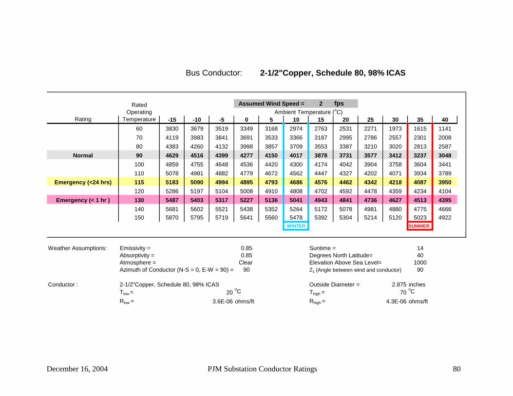
December 16, 2004 PJM Substation Conductor Ratings 80
Bus Conductor: 2-1/2"Copper, Schedule 80, 98% ICAS
2 fps
Rating -15 -10 -5 0 5 10 15 20 25 30 35 4060 3830 3679 3519 3349 3168 2974 2763 2531 2271 1973 1615 114170 4119 3983 3841 3691 3533 3366 3187 2995 2786 2557 2301 200880 4383 4260 4132 3998 3857 3709 3553 3387 3210 3020 2813 2587
Normal 90 4629 4516 4399 4277 4150 4017 3878 3731 3577 3412 3237 3048100 4859 4755 4648 4536 4420 4300 4174 4042 3904 3758 3604 3441110 5078 4981 4882 4779 4672 4562 4447 4327 4202 4071 3934 3789
Emergency (<24 hrs) 115 5183 5090 4994 4895 4793 4686 4576 4462 4342 4218 4087 3950120 5286 5197 5104 5008 4910 4808 4702 4592 4478 4359 4234 4104
Emergency (< 1 hr ) 130 5487 5403 5317 5227 5136 5041 4943 4841 4736 4627 4513 4395140 5681 5602 5521 5438 5352 5264 5172 5078 4981 4880 4775 4666150 5870 5795 5719 5641 5560 5478 5392 5304 5214 5120 5023 4922
WINTER SUMMER
Weather Assumptions: Emissivity = 0.85 Suntime = 14Absorptivity = 0.85 Degrees North Latitude= 40Atmosphere = Clear Elevation Above Sea Level= 1000Azimuth of Conductor (N-S = 0, E-W = 90) = 90 Z1 (Angle between wind and conductor) 90
Conductor : 2-1/2"Copper, Schedule 80, 98% ICAS Outside Diameter = 2.875 inchesTlow = 20
oC Thigh = 70oC
Rlow = 3.6E-06 ohms/ft Rhigh = 4.3E-06 ohms/ft
Ambient Temperature (oC)Assumed Wind Speed =Rated
Operating Temperature
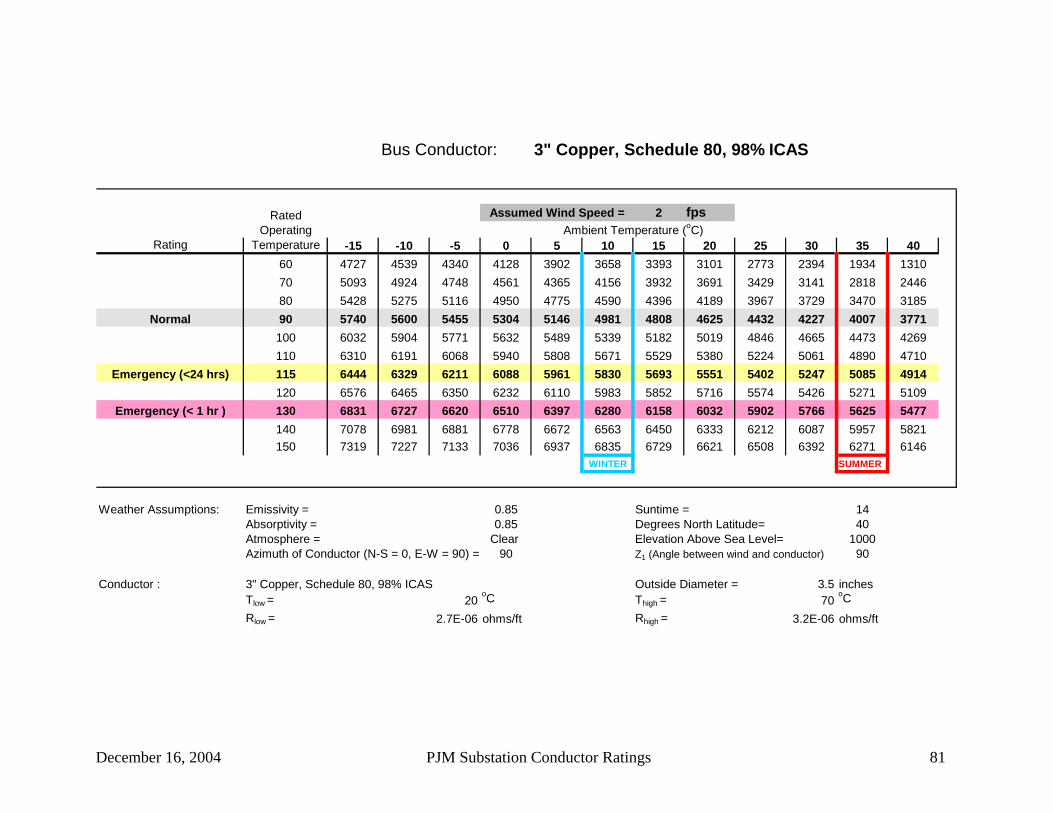
December 16, 2004 PJM Substation Conductor Ratings 81
Bus Conductor: 3" Copper, Schedule 80, 98% ICAS
2 fps
Rating -15 -10 -5 0 5 10 15 20 25 30 35 4060 4727 4539 4340 4128 3902 3658 3393 3101 2773 2394 1934 131070 5093 4924 4748 4561 4365 4156 3932 3691 3429 3141 2818 244680 5428 5275 5116 4950 4775 4590 4396 4189 3967 3729 3470 3185
Normal 90 5740 5600 5455 5304 5146 4981 4808 4625 4432 4227 4007 3771100 6032 5904 5771 5632 5489 5339 5182 5019 4846 4665 4473 4269110 6310 6191 6068 5940 5808 5671 5529 5380 5224 5061 4890 4710
Emergency (<24 hrs) 115 6444 6329 6211 6088 5961 5830 5693 5551 5402 5247 5085 4914120 6576 6465 6350 6232 6110 5983 5852 5716 5574 5426 5271 5109
Emergency (< 1 hr ) 130 6831 6727 6620 6510 6397 6280 6158 6032 5902 5766 5625 5477140 7078 6981 6881 6778 6672 6563 6450 6333 6212 6087 5957 5821150 7319 7227 7133 7036 6937 6835 6729 6621 6508 6392 6271 6146
WINTER SUMMER
Weather Assumptions: Emissivity = 0.85 Suntime = 14Absorptivity = 0.85 Degrees North Latitude= 40Atmosphere = Clear Elevation Above Sea Level= 1000Azimuth of Conductor (N-S = 0, E-W = 90) = 90 Z1 (Angle between wind and conductor) 90
Conductor : 3" Copper, Schedule 80, 98% ICAS Outside Diameter = 3.5 inchesTlow = 20
oC Thigh = 70oC
Rlow = 2.7E-06 ohms/ft Rhigh = 3.2E-06 ohms/ft
Ambient Temperature (oC)Assumed Wind Speed =Rated
Operating Temperature

December 16, 2004 PJM Substation Conductor Ratings 82
Bus Conductor: 3-1/2" Copper, Schedule 80, 98% ICAS
2 fps
Rating -15 -10 -5 0 5 10 15 20 25 30 35 4060 5449 5231 5000 4754 4491 4207 3898 3556 3172 2726 2180 142570 5878 5683 5478 5263 5034 4791 4531 4251 3945 3608 3230 279280 6272 6095 5911 5718 5515 5302 5076 4835 4577 4300 3998 3665
Normal 90 6638 6477 6309 6134 5952 5760 5559 5347 5123 4884 4629 4354100 6982 6834 6680 6520 6354 6180 5999 5809 5610 5399 5176 4939110 7309 7171 7029 6882 6729 6571 6406 6233 6053 5864 5666 5456
Emergency (<24 hrs) 115 7466 7334 7197 7055 6909 6757 6599 6434 6262 6082 5894 5696120 7621 7493 7361 7225 7084 6937 6786 6628 6464 6292 6113 5925
Emergency (< 1 hr ) 130 7922 7802 7679 7552 7421 7286 7145 7000 6849 6692 6528 6357140 8213 8101 7986 7867 7745 7618 7488 7353 7213 7068 6918 6761150 8496 8391 8283 8171 8057 7939 7817 7691 7561 7427 7287 7143
WINTER SUMMER
Weather Assumptions: Emissivity = 0.85 Suntime = 14Absorptivity = 0.85 Degrees North Latitude= 40Atmosphere = Clear Elevation Above Sea Level= 1000Azimuth of Conductor (N-S = 0, E-W = 90) = 90 Z1 (Angle between wind and conductor) 90
Conductor : 3-1/2" Copper, Schedule 80, 98% ICAS Outside Diameter = 4 inchesTlow = 20
oC Thigh = 70oC
Rlow = 2.2E-06 ohms/ft Rhigh = 2.7E-06 ohms/ft
Ambient Temperature (oC)Assumed Wind Speed =Rated
Operating Temperature

December 16, 2004 PJM Substation Conductor Ratings 83
Bus Conductor: 4" Copper, Schedule 80, 98% ICAS
2 fps
Rating -15 -10 -5 0 5 10 15 20 25 30 35 4060 6210 5960 5695 5413 5111 4784 4428 4034 3589 3071 2432 153070 6708 6484 6250 6002 5740 5462 5163 4840 4488 4100 3662 315480 7164 6962 6751 6530 6298 6053 5794 5517 5221 4902 4554 4170
Normal 90 7588 7404 7212 7012 6803 6584 6354 6111 5854 5579 5286 4969100 7987 7817 7642 7459 7269 7071 6863 6646 6417 6176 5920 5647110 8366 8209 8047 7879 7704 7523 7334 7137 6931 6714 6487 6246
Emergency (<24 hrs) 115 8549 8398 8241 8080 7912 7739 7558 7369 7173 6967 6751 6524120 8728 8582 8432 8276 8115 7948 7775 7594 7406 7210 7005 6789
Emergency (< 1 hr ) 130 9077 8941 8801 8656 8506 8352 8192 8025 7853 7673 7486 7290140 9416 9288 9157 9021 8882 8738 8589 8435 8275 8110 7937 7758150 9745 9625 9502 9375 9244 9110 8971 8827 8679 8525 8366 8200
WINTER SUMMER
Weather Assumptions: Emissivity = 0.85 Suntime = 14Absorptivity = 0.85 Degrees North Latitude= 40Atmosphere = Clear Elevation Above Sea Level= 1000Azimuth of Conductor (N-S = 0, E-W = 90) = 90 Z1 (Angle between wind and conductor) 90
Conductor : 4" Copper, Schedule 80, 98% ICAS Outside Diameter = 4.5 inchesTlow = 20
oC Thigh = 70oC
Rlow = 1.9E-06 ohms/ft Rhigh = 2.2E-06 ohms/ft
Ambient Temperature (oC)Assumed Wind Speed =Rated
Operating Temperature

December 16, 2004 PJM Substation Conductor Ratings 84
Bus Conductor: 1/0 ACSR 6/1
2 fps
Rating -15 -10 -5 0 5 10 15 20 25 30 35 4080 336 327 317 307 297 286 274 263 250 237 222 20790 349 340 332 322 313 303 293 282 271 260 247 234100 361 353 345 336 328 319 310 300 290 279 268 257
Normal 105 367 359 351 343 335 326 317 308 298 288 278 267110 372 365 357 349 341 333 324 316 306 297 287 277120 382 376 368 361 354 346 338 330 322 313 304 294
Emergency (<24 hrs) 130 392 386 379 372 365 358 351 343 335 327 319 310
Emergency (< 1 hr ) 140 401 395 389 383 376 369 362 355 348 341 333 325150 410 404 398 392 386 380 373 367 360 353 346 338160 418 413 407 402 396 390 384 378 371 365 358 351
WINTER SUMMER
Weather Assumptions: Emissivity = 0.7 Suntime = 14Absorptivity = 0.9 Degrees North Latitude= 40Atmosphere = Clear Elevation Above Sea Level= 1000Azimuth of Conductor (N-S = 0, E-W = 90) = 90 Z1 (Angle between wind and conductor) 90
Conductor : 1/0 ACSR 6/1 Outside Diameter = 0.398 inchesTlow = 25
oC Thigh = 75oC
Rlow = 0.00017 ohms/ft Rhigh = 0.00022 ohms/ft
Ambient Temperature (oC)Assumed Wind Speed =Rated
Operating Temperature

December 16, 2004 PJM Substation Conductor Ratings 85
Bus Conductor: 2/0 ACSR 6/1
2 fps
Rating -15 -10 -5 0 5 10 15 20 25 30 35 4080 383 373 362 350 338 326 313 299 285 270 253 23690 396 387 377 366 356 344 333 321 308 295 281 266100 409 400 390 381 371 361 350 339 328 316 304 291
Normal 105 414 406 397 388 378 368 358 348 337 326 314 302110 420 411 403 394 385 376 366 356 346 335 324 312120 430 422 414 406 398 389 380 371 362 352 342 331
Emergency (<24 hrs) 130 440 432 425 417 409 401 393 385 376 367 358 348
Emergency (< 1 hr ) 140 449 442 435 428 420 413 405 397 389 381 372 363150 457 451 444 438 431 424 417 409 402 394 386 378160 466 459 453 447 440 434 427 420 413 406 398 391
WINTER SUMMER
Weather Assumptions: Emissivity = 0.7 Suntime = 14Absorptivity = 0.9 Degrees North Latitude= 40Atmosphere = Clear Elevation Above Sea Level= 1000Azimuth of Conductor (N-S = 0, E-W = 90) = 90 Z1 (Angle between wind and conductor) 90
Conductor : 2/0 ACSR 6/1 Outside Diameter = 0.447 inchesTlow = 25
oC Thigh = 75oC
Rlow = 0.00013 ohms/ft Rhigh = 0.00018 ohms/ft
Ambient Temperature (oC)Assumed Wind Speed =Rated
Operating Temperature

December 16, 2004 PJM Substation Conductor Ratings 86
Bus Conductor: 3/0 ACSR 6/1
2 fps
Rating -15 -10 -5 0 5 10 15 20 25 30 35 4080 437 425 412 399 385 371 356 341 324 307 288 26890 451 440 429 417 405 392 379 365 350 335 319 302100 465 454 444 433 422 410 398 386 373 359 345 330
Normal 105 471 461 451 440 430 419 407 395 383 370 357 343110 477 467 458 448 437 427 416 404 393 380 368 354120 488 479 470 461 451 442 431 421 410 399 388 376
Emergency (<24 hrs) 130 498 490 482 473 464 455 446 436 426 416 406 395
Emergency (< 1 hr ) 140 508 501 493 485 476 468 459 450 441 432 422 412150 518 511 503 496 488 480 472 463 455 446 437 428160 527 520 513 506 498 491 483 476 468 459 451 442
WINTER SUMMER
Weather Assumptions: Emissivity = 0.7 Suntime = 14Absorptivity = 0.9 Degrees North Latitude= 40Atmosphere = Clear Elevation Above Sea Level= 1000Azimuth of Conductor (N-S = 0, E-W = 90) = 90 Z1 (Angle between wind and conductor) 90
Conductor : 3/0 ACSR 6/1 Outside Diameter = 0.502 inchesTlow = 25
oC Thigh = 75oC
Rlow = 0.0001 ohms/ft Rhigh = 0.00014 ohms/ft
Ambient Temperature (oC)Assumed Wind Speed =Rated
Operating Temperature

December 16, 2004 PJM Substation Conductor Ratings 87
Bus Conductor: 4/0 ACSR 6/1
2 fps
Rating -15 -10 -5 0 5 10 15 20 25 30 35 4080 496 482 468 453 437 421 404 386 368 348 326 30390 511 499 486 472 458 444 429 413 397 379 361 341100 526 514 502 490 477 464 450 436 422 406 390 373
Normal 105 532 521 510 498 486 473 460 447 433 418 403 387110 538 528 517 505 494 482 469 457 443 430 415 400120 550 540 530 520 509 498 487 475 463 450 437 424
Emergency (<24 hrs) 130 562 552 543 533 523 513 502 492 480 469 457 445
Emergency (< 1 hr ) 140 572 563 555 546 536 527 517 507 497 486 475 464150 582 574 566 557 548 540 530 521 512 502 492 481160 592 584 576 568 560 552 543 534 526 516 507 497
WINTER SUMMER
Weather Assumptions: Emissivity = 0.7 Suntime = 14Absorptivity = 0.9 Degrees North Latitude= 40Atmosphere = Clear Elevation Above Sea Level= 1000Azimuth of Conductor (N-S = 0, E-W = 90) = 90 Z1 (Angle between wind and conductor) 90
Conductor : 4/0 ACSR 6/1 Outside Diameter = 0.563 inchesTlow = 25
oC Thigh = 75oC
Rlow = 8.1E-05 ohms/ft Rhigh = 0.00012 ohms/ft
Ambient Temperature (oC)Assumed Wind Speed =Rated
Operating Temperature

December 16, 2004 PJM Substation Conductor Ratings 88
Bus Conductor: 159 kcm ACSR 12/7
2 fps
Rating -15 -10 -5 0 5 10 15 20 25 30 35 4080 433 421 408 395 381 367 352 336 320 302 283 26290 443 432 421 409 397 384 371 357 343 328 311 294100 452 442 432 421 410 399 387 375 362 349 335 320
Normal 105 456 447 437 427 416 405 394 383 371 358 345 331110 460 451 442 432 422 412 401 390 379 367 354 341120 468 459 451 442 433 423 414 404 393 383 372 360
Emergency (<24 hrs) 130 475 467 459 451 442 434 425 416 406 397 387 376
Emergency (< 1 hr ) 140 482 474 467 459 452 444 435 427 418 409 400 391150 488 481 474 467 460 453 445 437 429 421 413 404160 494 488 482 475 468 461 454 447 440 432 424 416
WINTER SUMMER
Weather Assumptions: Emissivity = 0.7 Suntime = 14Absorptivity = 0.9 Degrees North Latitude= 40Atmosphere = Clear Elevation Above Sea Level= 1000Azimuth of Conductor (N-S = 0, E-W = 90) = 90 Z1 (Angle between wind and conductor) 90
Conductor : 159 kcm ACSR 12/7 Outside Diameter = 0.756 inchesTlow = 25
oC Thigh = 75oC
Rlow = 0.0001 ohms/ft Rhigh = 0.00018 ohms/ft
Ambient Temperature (oC)Assumed Wind Speed =Rated
Operating Temperature

December 16, 2004 PJM Substation Conductor Ratings 89
Bus Conductor: 203.2 kcm ACSR 16/19
2 fps
Rating -15 -10 -5 0 5 10 15 20 25 30 35 4080 459 446 433 419 405 389 374 357 339 321 300 27990 467 455 443 431 418 405 391 377 361 345 328 310100 474 463 453 442 430 418 406 393 380 366 351 336
Normal 105 477 467 457 446 435 424 413 400 388 375 361 347110 480 471 461 451 440 430 419 407 395 383 370 357120 486 478 469 459 450 440 430 420 409 398 386 374
Emergency (<24 hrs) 130 492 484 476 467 459 450 440 431 421 411 401 390
Emergency (< 1 hr ) 140 498 490 482 475 467 458 450 441 432 423 413 404150 503 496 489 482 474 466 459 451 442 434 425 416160 508 502 495 488 481 474 467 459 452 444 436 428
WINTER SUMMER
Weather Assumptions: Emissivity = 0.7 Suntime = 14Absorptivity = 0.9 Degrees North Latitude= 40Atmosphere = Clear Elevation Above Sea Level= 1000Azimuth of Conductor (N-S = 0, E-W = 90) = 90 Z1 (Angle between wind and conductor) 90
Conductor : 203.2 kcm ACSR 16/19 Outside Diameter = 0.714 inchesTlow = 25
oC Thigh = 75oC
Rlow = 7.8E-05 ohms/ft Rhigh = 0.00016 ohms/ft
Ambient Temperature (oC)Assumed Wind Speed =Rated
Operating Temperature

December 16, 2004 PJM Substation Conductor Ratings 90
Bus Conductor: 266.8 kcm ACSR 26/7
2 fps
Rating -15 -10 -5 0 5 10 15 20 25 30 35 4080 640 622 603 584 564 543 521 498 474 448 420 39090 670 653 636 618 600 581 561 541 519 496 472 446100 697 682 666 650 633 616 597 579 559 539 517 494
Normal 105 711 696 680 665 648 632 614 596 578 558 538 516110 723 709 694 679 663 647 631 613 595 577 557 537120 748 734 720 706 692 677 661 645 629 612 594 576
Emergency (<24 hrs) 130 771 758 745 732 718 704 690 675 660 644 628 611
Emergency (< 1 hr ) 140 793 781 769 756 743 730 717 703 689 674 659 643150 814 803 791 779 767 755 742 729 716 702 688 673160 835 824 813 802 790 778 766 754 742 729 715 702
WINTER SUMMER
Weather Assumptions: Emissivity = 0.7 Suntime = 14Absorptivity = 0.9 Degrees North Latitude= 40Atmosphere = Clear Elevation Above Sea Level= 1000Azimuth of Conductor (N-S = 0, E-W = 90) = 90 Z1 (Angle between wind and conductor) 90
Conductor : 266.8 kcm ACSR 26/7 Outside Diameter = 0.642 inchesTlow = 25
oC Thigh = 75oC
Rlow = 6.5E-05 ohms/ft Rhigh = 7.8E-05 ohms/ft
Ambient Temperature (oC)Assumed Wind Speed =Rated
Operating Temperature

December 16, 2004 PJM Substation Conductor Ratings 91
Bus Conductor: 266.8 kcm ACSR 30/7
2 fps
Rating -15 -10 -5 0 5 10 15 20 25 30 35 4080 647 629 610 591 570 549 527 504 479 452 424 39490 677 661 643 626 607 588 568 547 525 502 477 451100 705 690 674 657 640 623 604 585 566 545 523 500
Normal 105 719 704 688 672 656 639 622 603 584 565 544 522110 732 717 702 687 671 655 638 621 602 584 564 543120 757 743 729 715 700 685 669 653 636 619 601 582
Emergency (<24 hrs) 130 780 767 754 741 727 713 698 683 668 652 635 618
Emergency (< 1 hr ) 140 803 790 778 765 752 739 725 711 697 682 667 651150 824 813 801 789 777 764 751 738 725 711 696 682160 845 834 823 812 800 788 776 764 751 738 724 711
WINTER SUMMER
Weather Assumptions: Emissivity = 0.7 Suntime = 14Absorptivity = 0.9 Degrees North Latitude= 40Atmosphere = Clear Elevation Above Sea Level= 1000Azimuth of Conductor (N-S = 0, E-W = 90) = 90 Z1 (Angle between wind and conductor) 90
Conductor : 266.8 kcm ACSR 30/7 Outside Diameter = 0.66 inchesTlow = 25
oC Thigh = 75oC
Rlow = 6.5E-05 ohms/ft Rhigh = 7.7E-05 ohms/ft
Ambient Temperature (oC)Assumed Wind Speed =Rated
Operating Temperature

December 16, 2004 PJM Substation Conductor Ratings 92
Bus Conductor: 336.4 kcm ACSR 18/1
2 fps
Rating -15 -10 -5 0 5 10 15 20 25 30 35 4080 727 707 686 664 641 617 592 566 538 508 476 44290 761 742 723 703 682 660 638 614 590 564 536 507100 793 775 758 739 720 700 679 658 636 612 588 562
Normal 105 808 791 774 756 737 718 699 678 657 635 611 587110 823 806 790 772 755 736 717 698 677 656 634 611120 851 835 820 804 787 770 752 734 715 696 676 655
Emergency (<24 hrs) 130 877 863 848 833 817 801 785 768 751 733 714 695
Emergency (< 1 hr ) 140 903 889 875 861 846 831 816 800 784 767 750 732150 927 914 901 887 874 860 845 830 815 799 783 767160 950 938 926 913 900 887 873 859 845 830 815 799
WINTER SUMMER
Weather Assumptions: Emissivity = 0.7 Suntime = 14Absorptivity = 0.9 Degrees North Latitude= 40Atmosphere = Clear Elevation Above Sea Level= 1000Azimuth of Conductor (N-S = 0, E-W = 90) = 90 Z1 (Angle between wind and conductor) 90
Conductor : 336.4 kcm ACSR 18/1 Outside Diameter = 0.684 inchesTlow = 25
oC Thigh = 75oC
Rlow = 5.2E-05 ohms/ft Rhigh = 6.2E-05 ohms/ft
Ambient Temperature (oC)Assumed Wind Speed =Rated
Operating Temperature

December 16, 2004 PJM Substation Conductor Ratings 93
Bus Conductor: 336.4 kcm ACSR 26/7
2 fps
Rating -15 -10 -5 0 5 10 15 20 25 30 35 4080 741 721 699 677 653 629 603 576 548 518 485 45090 776 757 737 717 696 673 650 626 601 574 546 516100 809 791 773 754 734 714 693 671 648 624 599 573
Normal 105 824 807 789 771 752 733 713 692 670 647 624 599110 839 823 806 788 770 751 732 712 691 669 647 623120 868 852 836 820 803 786 768 749 730 710 690 668
Emergency (<24 hrs) 130 895 881 866 850 834 818 801 784 766 748 729 709
Emergency (< 1 hr ) 140 921 908 893 879 864 849 833 817 800 783 766 748150 946 933 920 906 892 878 863 848 832 817 800 783160 971 958 945 932 919 906 892 877 863 848 832 817
WINTER SUMMER
Weather Assumptions: Emissivity = 0.7 Suntime = 14Absorptivity = 0.9 Degrees North Latitude= 40Atmosphere = Clear Elevation Above Sea Level= 1000Azimuth of Conductor (N-S = 0, E-W = 90) = 90 Z1 (Angle between wind and conductor) 90
Conductor : 336.4 kcm ACSR 26/7 Outside Diameter = 0.72 inchesTlow = 25
oC Thigh = 75oC
Rlow = 5.2E-05 ohms/ft Rhigh = 6.2E-05 ohms/ft
Ambient Temperature (oC)Assumed Wind Speed =Rated
Operating Temperature

December 16, 2004 PJM Substation Conductor Ratings 94
Bus Conductor: 336.4 kcm ACSR 30/7
2 fps
Rating -15 -10 -5 0 5 10 15 20 25 30 35 4080 750 729 707 684 661 636 610 583 554 523 490 45590 786 766 746 725 704 681 658 634 608 581 552 522100 819 801 782 763 743 722 701 679 656 632 606 580
Normal 105 834 817 799 781 761 742 721 700 678 655 631 606110 850 833 815 798 779 760 741 720 699 677 655 631120 879 863 847 830 813 795 777 759 739 719 698 676
Emergency (<24 hrs) 130 906 892 876 861 845 828 811 794 776 757 738 718
Emergency (< 1 hr ) 140 933 919 905 890 875 859 844 827 811 793 775 757150 958 945 931 918 903 889 874 859 843 827 810 793160 983 970 957 944 931 917 903 889 874 859 843 827
WINTER SUMMER
Weather Assumptions: Emissivity = 0.7 Suntime = 14Absorptivity = 0.9 Degrees North Latitude= 40Atmosphere = Clear Elevation Above Sea Level= 1000Azimuth of Conductor (N-S = 0, E-W = 90) = 90 Z1 (Angle between wind and conductor) 90
Conductor : 336.4 kcm ACSR 30/7 Outside Diameter = 0.741 inchesTlow = 25
oC Thigh = 75oC
Rlow = 5.1E-05 ohms/ft Rhigh = 6.1E-05 ohms/ft
Ambient Temperature (oC)Assumed Wind Speed =Rated
Operating Temperature

December 16, 2004 PJM Substation Conductor Ratings 95
Bus Conductor: 397.5 kcm ACSR 26/7
2 fps
Rating -15 -10 -5 0 5 10 15 20 25 30 35 4080 824 801 777 752 726 699 671 640 609 575 538 49990 864 843 820 798 774 749 724 697 668 639 607 574100 900 881 860 839 817 795 771 747 721 695 667 637
Normal 105 918 899 879 859 838 816 794 770 746 721 694 666110 935 916 897 878 857 837 815 793 770 745 720 694120 967 950 932 914 895 876 856 835 814 791 768 745
Emergency (<24 hrs) 130 998 982 965 948 930 912 893 874 854 834 813 791
Emergency (< 1 hr ) 140 1027 1012 996 980 963 946 929 911 893 874 854 834150 1055 1041 1026 1011 995 979 963 946 929 911 893 874160 1083 1069 1055 1040 1026 1010 995 979 963 946 929 911
WINTER SUMMER
Weather Assumptions: Emissivity = 0.7 Suntime = 14Absorptivity = 0.9 Degrees North Latitude= 40Atmosphere = Clear Elevation Above Sea Level= 1000Azimuth of Conductor (N-S = 0, E-W = 90) = 90 Z1 (Angle between wind and conductor) 90
Conductor : 397.5 kcm ACSR 26/7 Outside Diameter = 0.783 inchesTlow = 25
oC Thigh = 75oC
Rlow = 4.4E-05 ohms/ft Rhigh = 5.2E-05 ohms/ft
Ambient Temperature (oC)Assumed Wind Speed =Rated
Operating Temperature

December 16, 2004 PJM Substation Conductor Ratings 96
Bus Conductor: 397.5 kcm ACSR 30/7
2 fps
Rating -15 -10 -5 0 5 10 15 20 25 30 35 4080 834 811 787 761 735 707 678 648 616 581 544 50490 874 853 830 807 783 758 732 705 676 646 614 580100 912 891 871 849 827 804 781 756 730 703 675 645
Normal 105 929 910 890 869 848 826 803 780 755 730 703 675110 946 928 908 889 868 847 825 803 779 755 729 702120 979 962 944 925 906 887 866 845 824 801 778 754
Emergency (<24 hrs) 130 1011 994 977 960 942 924 905 885 865 845 823 801
Emergency (< 1 hr ) 140 1040 1025 1009 993 976 959 941 923 904 885 865 845150 1069 1054 1039 1024 1008 992 975 958 941 923 904 885160 1097 1083 1069 1054 1039 1024 1008 992 976 959 941 924
WINTER SUMMER
Weather Assumptions: Emissivity = 0.7 Suntime = 14Absorptivity = 0.9 Degrees North Latitude= 40Atmosphere = Clear Elevation Above Sea Level= 1000Azimuth of Conductor (N-S = 0, E-W = 90) = 90 Z1 (Angle between wind and conductor) 90
Conductor : 397.5 kcm ACSR 30/7 Outside Diameter = 0.806 inchesTlow = 25
oC Thigh = 75oC
Rlow = 4.3E-05 ohms/ft Rhigh = 5.2E-05 ohms/ft
Ambient Temperature (oC)Assumed Wind Speed =Rated
Operating Temperature

December 16, 2004 PJM Substation Conductor Ratings 97
Bus Conductor: 477 kcm ACSR 26/7
2 fps
Rating -15 -10 -5 0 5 10 15 20 25 30 35 4080 926 900 873 845 816 785 753 719 683 644 603 55990 971 947 922 896 870 842 813 783 751 717 682 644100 1013 990 967 944 919 894 867 840 811 781 749 716
Normal 105 1032 1011 989 966 942 918 893 866 839 810 781 749110 1052 1031 1009 987 965 941 917 892 866 838 810 780120 1088 1069 1049 1028 1007 985 963 940 916 891 865 838
Emergency (<24 hrs) 130 1123 1105 1086 1067 1047 1027 1006 984 962 939 915 891
Emergency (< 1 hr ) 140 1157 1140 1122 1104 1085 1066 1047 1026 1006 984 962 939150 1189 1173 1156 1139 1121 1103 1085 1066 1047 1027 1006 985160 1220 1205 1189 1173 1156 1139 1122 1104 1086 1067 1048 1028
WINTER SUMMER
Weather Assumptions: Emissivity = 0.7 Suntime = 14Absorptivity = 0.9 Degrees North Latitude= 40Atmosphere = Clear Elevation Above Sea Level= 1000Azimuth of Conductor (N-S = 0, E-W = 90) = 90 Z1 (Angle between wind and conductor) 90
Conductor : 477 kcm ACSR 26/7 Outside Diameter = 0.858 inchesTlow = 25
oC Thigh = 75oC
Rlow = 3.7E-05 ohms/ft Rhigh = 4.4E-05 ohms/ft
Ambient Temperature (oC)Assumed Wind Speed =Rated
Operating Temperature

December 16, 2004 PJM Substation Conductor Ratings 98
Bus Conductor: 556. 5 kcm ACSR 24/7
2 fps
Rating -15 -10 -5 0 5 10 15 20 25 30 35 4080 1015 986 957 926 894 860 825 787 748 705 660 61190 1064 1038 1011 983 953 923 891 858 823 786 747 705100 1110 1086 1061 1035 1008 980 951 921 889 856 822 785
Normal 105 1132 1109 1084 1059 1034 1007 979 950 920 889 856 821110 1154 1131 1107 1083 1058 1033 1006 978 950 920 888 856120 1194 1173 1151 1129 1105 1081 1057 1031 1005 978 949 919
Emergency (<24 hrs) 130 1233 1213 1192 1171 1150 1127 1104 1081 1056 1031 1005 978
Emergency (< 1 hr ) 140 1270 1251 1232 1212 1192 1171 1149 1127 1104 1081 1057 1032150 1306 1288 1270 1251 1232 1212 1192 1171 1150 1128 1105 1082160 1340 1323 1306 1288 1270 1251 1232 1213 1193 1172 1151 1129
WINTER SUMMER
Weather Assumptions: Emissivity = 0.7 Suntime = 14Absorptivity = 0.9 Degrees North Latitude= 40Atmosphere = Clear Elevation Above Sea Level= 1000Azimuth of Conductor (N-S = 0, E-W = 90) = 90 Z1 (Angle between wind and conductor) 90
Conductor : 556. 5 kcm ACSR 24/7 Outside Diameter = 0.914 inchesTlow = 25
oC Thigh = 75oC
Rlow = 3.1E-05 ohms/ft Rhigh = 3.8E-05 ohms/ft
Ambient Temperature (oC)Assumed Wind Speed =Rated
Operating Temperature

December 16, 2004 PJM Substation Conductor Ratings 99
Bus Conductor: 556.5 kcm ACSR 26/7
2 fps
Rating -15 -10 -5 0 5 10 15 20 25 30 35 4080 1022 993 963 932 899 865 830 792 752 710 664 61590 1071 1045 1017 989 960 929 897 863 828 791 751 709100 1118 1093 1068 1042 1015 986 957 927 895 862 827 790
Normal 105 1140 1116 1092 1067 1040 1013 986 957 926 895 862 827110 1161 1138 1115 1091 1065 1040 1013 985 956 926 894 862120 1203 1181 1159 1136 1113 1089 1064 1038 1012 984 956 926
Emergency (<24 hrs) 130 1242 1221 1201 1179 1158 1135 1112 1088 1064 1038 1012 984
Emergency (< 1 hr ) 140 1279 1260 1241 1221 1200 1179 1157 1135 1112 1088 1064 1039150 1315 1297 1279 1260 1240 1221 1200 1179 1158 1136 1113 1090160 1350 1333 1315 1297 1279 1260 1241 1222 1202 1181 1160 1138
WINTER SUMMER
Weather Assumptions: Emissivity = 0.7 Suntime = 14Absorptivity = 0.9 Degrees North Latitude= 40Atmosphere = Clear Elevation Above Sea Level= 1000Azimuth of Conductor (N-S = 0, E-W = 90) = 90 Z1 (Angle between wind and conductor) 90
Conductor : 556.5 kcm ACSR 26/7 Outside Diameter = 0.927 inchesTlow = 25
oC Thigh = 75oC
Rlow = 3.1E-05 ohms/ft Rhigh = 3.7E-05 ohms/ft
Ambient Temperature (oC)Assumed Wind Speed =Rated
Operating Temperature

December 16, 2004 PJM Substation Conductor Ratings 100
Bus Conductor: 556.5 kcm ACSR 30/7
2 fps
Rating -15 -10 -5 0 5 10 15 20 25 30 35 4080 1033 1004 974 943 910 875 839 801 761 718 671 62190 1084 1057 1029 1001 971 940 907 873 838 800 760 717100 1131 1106 1081 1054 1027 998 969 938 906 872 837 799
Normal 105 1154 1130 1105 1079 1053 1026 997 968 937 905 872 837110 1175 1152 1128 1104 1078 1052 1025 997 967 937 905 872120 1217 1195 1173 1150 1126 1102 1077 1051 1024 996 967 937
Emergency (<24 hrs) 130 1257 1236 1215 1194 1172 1149 1126 1102 1077 1051 1024 997
Emergency (< 1 hr ) 140 1295 1276 1256 1236 1215 1194 1172 1149 1126 1102 1077 1052150 1331 1313 1294 1275 1256 1236 1215 1194 1172 1150 1127 1103160 1367 1349 1332 1314 1295 1276 1257 1237 1217 1196 1174 1152
WINTER SUMMER
Weather Assumptions: Emissivity = 0.7 Suntime = 14Absorptivity = 0.9 Degrees North Latitude= 40Atmosphere = Clear Elevation Above Sea Level= 1000Azimuth of Conductor (N-S = 0, E-W = 90) = 90 Z1 (Angle between wind and conductor) 90
Conductor : 556.5 kcm ACSR 30/7 Outside Diameter = 0.953 inchesTlow = 25
oC Thigh = 75oC
Rlow = 3.1E-05 ohms/ft Rhigh = 3.7E-05 ohms/ft
Ambient Temperature (oC)Assumed Wind Speed =Rated
Operating Temperature

December 16, 2004 PJM Substation Conductor Ratings 101
Bus Conductor: 605 kcm ACSR 24/7
2 fps
Rating -15 -10 -5 0 5 10 15 20 25 30 35 4080 1070 1040 1009 976 942 907 869 830 788 743 695 64390 1123 1095 1066 1036 1006 973 940 904 867 828 787 743100 1172 1146 1119 1092 1063 1034 1003 971 938 903 867 828
Normal 105 1195 1170 1144 1118 1091 1062 1033 1003 971 938 903 867110 1218 1194 1169 1143 1117 1090 1062 1032 1002 971 938 903120 1261 1238 1215 1191 1167 1142 1116 1089 1061 1032 1002 971
Emergency (<24 hrs) 130 1302 1281 1259 1237 1214 1190 1166 1141 1115 1089 1061 1032
Emergency (< 1 hr ) 140 1342 1322 1301 1280 1259 1237 1214 1191 1167 1142 1116 1090150 1379 1361 1341 1321 1301 1280 1259 1237 1215 1192 1168 1143160 1416 1398 1380 1361 1342 1322 1302 1282 1261 1239 1217 1194
WINTER SUMMER
Weather Assumptions: Emissivity = 0.7 Suntime = 14Absorptivity = 0.9 Degrees North Latitude= 40Atmosphere = Clear Elevation Above Sea Level= 1000Azimuth of Conductor (N-S = 0, E-W = 90) = 90 Z1 (Angle between wind and conductor) 90
Conductor : 605 kcm ACSR 24/7 Outside Diameter = 0.953 inchesTlow = 25
oC Thigh = 75oC
Rlow = 2.9E-05 ohms/ft Rhigh = 3.5E-05 ohms/ft
Ambient Temperature (oC)Assumed Wind Speed =Rated
Operating Temperature
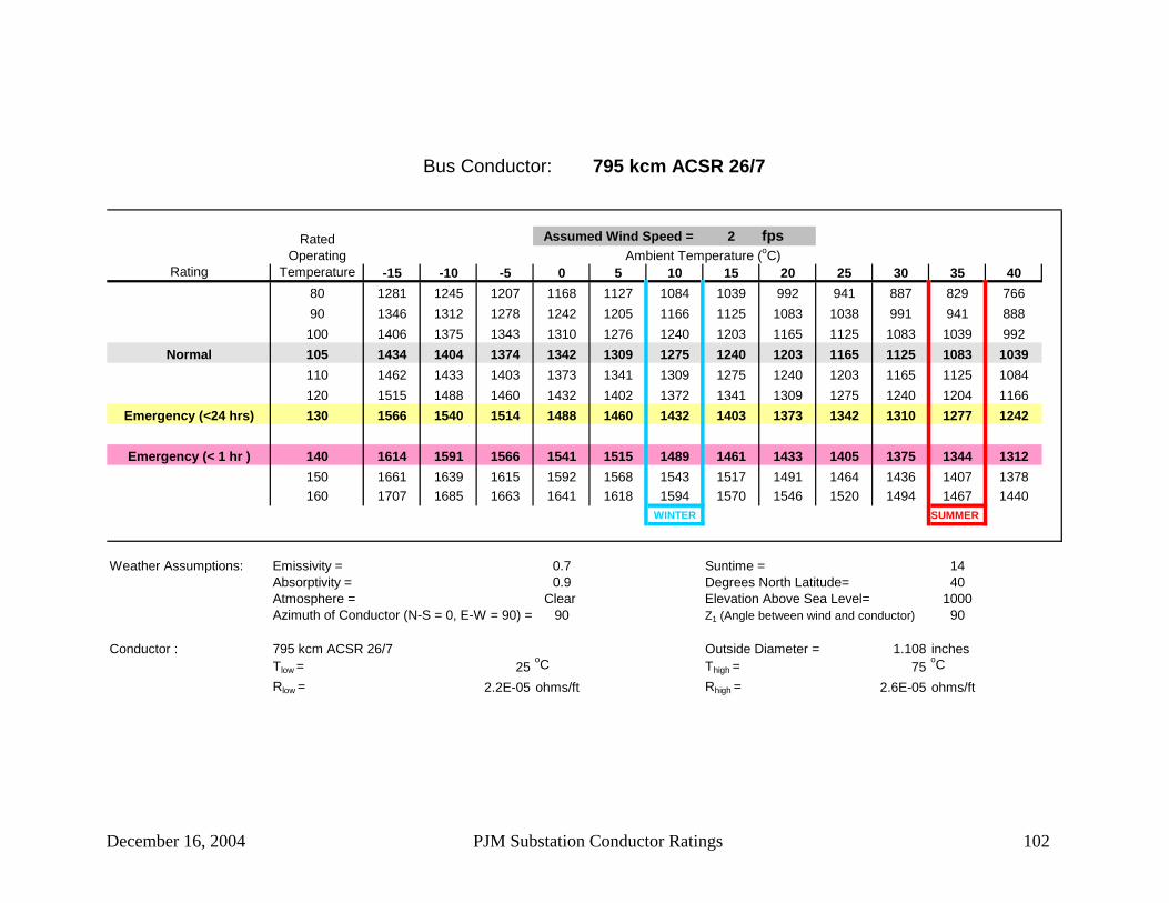
December 16, 2004 PJM Substation Conductor Ratings 102
Bus Conductor: 795 kcm ACSR 26/7
2 fps
Rating -15 -10 -5 0 5 10 15 20 25 30 35 4080 1281 1245 1207 1168 1127 1084 1039 992 941 887 829 76690 1346 1312 1278 1242 1205 1166 1125 1083 1038 991 941 888100 1406 1375 1343 1310 1276 1240 1203 1165 1125 1083 1039 992
Normal 105 1434 1404 1374 1342 1309 1275 1240 1203 1165 1125 1083 1039110 1462 1433 1403 1373 1341 1309 1275 1240 1203 1165 1125 1084120 1515 1488 1460 1432 1402 1372 1341 1309 1275 1240 1204 1166
Emergency (<24 hrs) 130 1566 1540 1514 1488 1460 1432 1403 1373 1342 1310 1277 1242
Emergency (< 1 hr ) 140 1614 1591 1566 1541 1515 1489 1461 1433 1405 1375 1344 1312150 1661 1639 1615 1592 1568 1543 1517 1491 1464 1436 1407 1378160 1707 1685 1663 1641 1618 1594 1570 1546 1520 1494 1467 1440
WINTER SUMMER
Weather Assumptions: Emissivity = 0.7 Suntime = 14Absorptivity = 0.9 Degrees North Latitude= 40Atmosphere = Clear Elevation Above Sea Level= 1000Azimuth of Conductor (N-S = 0, E-W = 90) = 90 Z1 (Angle between wind and conductor) 90
Conductor : 795 kcm ACSR 26/7 Outside Diameter = 1.108 inchesTlow = 25
oC Thigh = 75oC
Rlow = 2.2E-05 ohms/ft Rhigh = 2.6E-05 ohms/ft
Ambient Temperature (oC)Assumed Wind Speed =Rated
Operating Temperature

December 16, 2004 PJM Substation Conductor Ratings 103
Bus Conductor: 795 kcm ACSR 30/7
2 fps
Rating -15 -10 -5 0 5 10 15 20 25 30 35 4080 1297 1260 1222 1182 1141 1097 1051 1003 952 897 838 77490 1362 1328 1293 1257 1219 1180 1139 1096 1051 1003 952 898100 1423 1391 1359 1326 1291 1255 1218 1179 1138 1096 1051 1004
Normal 105 1452 1421 1390 1358 1325 1290 1255 1218 1179 1139 1096 1052110 1480 1450 1420 1389 1358 1324 1290 1255 1218 1179 1139 1097120 1534 1506 1478 1449 1420 1389 1357 1325 1291 1255 1219 1181
Emergency (<24 hrs) 130 1585 1559 1533 1506 1478 1450 1420 1390 1358 1326 1292 1257
Emergency (< 1 hr ) 140 1634 1610 1585 1560 1534 1507 1480 1451 1422 1392 1361 1328150 1682 1659 1635 1611 1587 1562 1536 1509 1482 1454 1425 1395160 1728 1706 1684 1661 1638 1614 1590 1565 1539 1513 1486 1458
WINTER SUMMER
Weather Assumptions: Emissivity = 0.7 Suntime = 14Absorptivity = 0.9 Degrees North Latitude= 40Atmosphere = Clear Elevation Above Sea Level= 1000Azimuth of Conductor (N-S = 0, E-W = 90) = 90 Z1 (Angle between wind and conductor) 90
Conductor : 795 kcm ACSR 30/7 Outside Diameter = 1.14 inchesTlow = 25
oC Thigh = 75oC
Rlow = 2.2E-05 ohms/ft Rhigh = 2.6E-05 ohms/ft
Ambient Temperature (oC)Assumed Wind Speed =Rated
Operating Temperature

December 16, 2004 PJM Substation Conductor Ratings 104
Bus Conductor: 795 kcm ACSR 30/19
2 fps
Rating -15 -10 -5 0 5 10 15 20 25 30 35 4080 1296 1260 1221 1182 1140 1097 1051 1003 952 897 838 77490 1361 1328 1293 1256 1219 1180 1139 1096 1050 1003 952 898100 1422 1391 1359 1325 1291 1255 1217 1179 1138 1095 1051 1003
Normal 105 1451 1421 1390 1358 1324 1290 1254 1217 1179 1138 1096 1051110 1479 1450 1420 1389 1357 1324 1290 1254 1217 1179 1139 1096120 1533 1506 1478 1449 1419 1389 1357 1324 1290 1255 1218 1180
Emergency (<24 hrs) 130 1585 1559 1533 1506 1478 1449 1420 1389 1358 1326 1292 1257
Emergency (< 1 hr ) 140 1634 1610 1585 1559 1533 1507 1479 1451 1422 1391 1360 1328150 1681 1658 1635 1611 1586 1561 1535 1509 1482 1453 1424 1395160 1727 1705 1683 1661 1637 1614 1589 1564 1539 1512 1485 1457
WINTER SUMMER
Weather Assumptions: Emissivity = 0.7 Suntime = 14Absorptivity = 0.9 Degrees North Latitude= 40Atmosphere = Clear Elevation Above Sea Level= 1000Azimuth of Conductor (N-S = 0, E-W = 90) = 90 Z1 (Angle between wind and conductor) 90
Conductor : 795 kcm ACSR 30/19 Outside Diameter = 1.14 inchesTlow = 25
oC Thigh = 75oC
Rlow = 2.2E-05 ohms/ft Rhigh = 2.6E-05 ohms/ft
Ambient Temperature (oC)Assumed Wind Speed =Rated
Operating Temperature
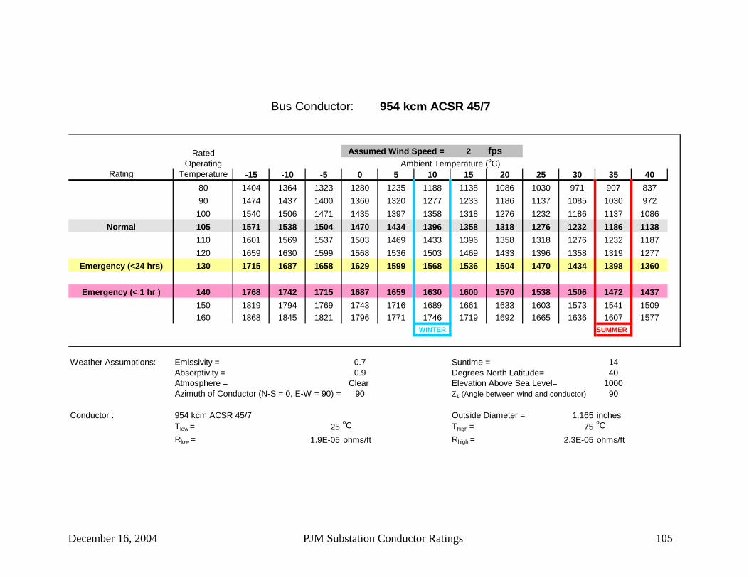
December 16, 2004 PJM Substation Conductor Ratings 105
Bus Conductor: 954 kcm ACSR 45/7
2 fps
Rating -15 -10 -5 0 5 10 15 20 25 30 35 4080 1404 1364 1323 1280 1235 1188 1138 1086 1030 971 907 83790 1474 1437 1400 1360 1320 1277 1233 1186 1137 1085 1030 972100 1540 1506 1471 1435 1397 1358 1318 1276 1232 1186 1137 1086
Normal 105 1571 1538 1504 1470 1434 1396 1358 1318 1276 1232 1186 1138110 1601 1569 1537 1503 1469 1433 1396 1358 1318 1276 1232 1187120 1659 1630 1599 1568 1536 1503 1469 1433 1396 1358 1319 1277
Emergency (<24 hrs) 130 1715 1687 1658 1629 1599 1568 1536 1504 1470 1434 1398 1360
Emergency (< 1 hr ) 140 1768 1742 1715 1687 1659 1630 1600 1570 1538 1506 1472 1437150 1819 1794 1769 1743 1716 1689 1661 1633 1603 1573 1541 1509160 1868 1845 1821 1796 1771 1746 1719 1692 1665 1636 1607 1577
WINTER SUMMER
Weather Assumptions: Emissivity = 0.7 Suntime = 14Absorptivity = 0.9 Degrees North Latitude= 40Atmosphere = Clear Elevation Above Sea Level= 1000Azimuth of Conductor (N-S = 0, E-W = 90) = 90 Z1 (Angle between wind and conductor) 90
Conductor : 954 kcm ACSR 45/7 Outside Diameter = 1.165 inchesTlow = 25
oC Thigh = 75oC
Rlow = 1.9E-05 ohms/ft Rhigh = 2.3E-05 ohms/ft
Ambient Temperature (oC)Assumed Wind Speed =Rated
Operating Temperature

December 16, 2004 PJM Substation Conductor Ratings 106
Bus Conductor: 954 kcm ACSR 48/7
2 fps
Rating -15 -10 -5 0 5 10 15 20 25 30 35 4080 1402 1362 1321 1278 1233 1186 1137 1084 1029 970 906 83690 1472 1435 1397 1358 1317 1275 1231 1184 1135 1083 1028 970100 1536 1502 1468 1432 1394 1355 1315 1273 1229 1183 1135 1084
Normal 105 1567 1534 1501 1466 1430 1393 1355 1314 1273 1229 1183 1135110 1597 1565 1533 1500 1465 1429 1392 1354 1314 1273 1229 1184120 1654 1625 1594 1563 1531 1498 1464 1429 1392 1354 1315 1273
Emergency (<24 hrs) 130 1709 1681 1653 1624 1594 1563 1531 1498 1465 1430 1393 1356
Emergency (< 1 hr ) 140 1761 1735 1708 1681 1653 1624 1594 1564 1532 1500 1466 1431150 1811 1786 1761 1735 1709 1682 1654 1626 1596 1566 1535 1503160 1859 1836 1812 1788 1763 1738 1711 1685 1657 1629 1600 1569
WINTER SUMMER
Weather Assumptions: Emissivity = 0.7 Suntime = 14Absorptivity = 0.9 Degrees North Latitude= 40Atmosphere = Clear Elevation Above Sea Level= 1000Azimuth of Conductor (N-S = 0, E-W = 90) = 90 Z1 (Angle between wind and conductor) 90
Conductor : 954 kcm ACSR 48/7 Outside Diameter = 1.175 inchesTlow = 25
oC Thigh = 75oC
Rlow = 1.9E-05 ohms/ft Rhigh = 2.3E-05 ohms/ft
Ambient Temperature (oC)Assumed Wind Speed =Rated
Operating Temperature

December 16, 2004 PJM Substation Conductor Ratings 107
Bus Conductor: 1033.5 kcm ACSR 45/7
2 fps
Rating -15 -10 -5 0 5 10 15 20 25 30 35 4080 1476 1434 1390 1345 1298 1248 1196 1141 1082 1020 952 87990 1550 1512 1472 1431 1388 1343 1296 1247 1195 1141 1083 1021100 1620 1584 1547 1509 1470 1429 1386 1342 1296 1247 1196 1142
Normal 105 1653 1618 1583 1546 1509 1469 1429 1386 1342 1296 1248 1197110 1685 1652 1618 1582 1546 1508 1469 1429 1387 1343 1297 1249120 1747 1716 1684 1651 1617 1582 1546 1509 1470 1430 1388 1345
Emergency (<24 hrs) 130 1805 1776 1746 1716 1684 1651 1618 1583 1548 1511 1472 1432
Emergency (< 1 hr ) 140 1862 1834 1806 1777 1748 1717 1686 1654 1620 1586 1551 1514150 1916 1890 1863 1836 1808 1780 1750 1720 1689 1657 1624 1590160 1968 1944 1919 1893 1867 1840 1812 1784 1754 1724 1694 1662
WINTER SUMMER
Weather Assumptions: Emissivity = 0.7 Suntime = 14Absorptivity = 0.9 Degrees North Latitude= 40Atmosphere = Clear Elevation Above Sea Level= 1000Azimuth of Conductor (N-S = 0, E-W = 90) = 90 Z1 (Angle between wind and conductor) 90
Conductor : 1033.5 kcm ACSR 45/7 Outside Diameter = 1.212 inchesTlow = 25
oC Thigh = 75oC
Rlow = 1.7E-05 ohms/ft Rhigh = 2.1E-05 ohms/ft
Ambient Temperature (oC)Assumed Wind Speed =Rated
Operating Temperature

December 16, 2004 PJM Substation Conductor Ratings 108
Bus Conductor: 1033.5 kcm ACSR 54/7
2 fps
Rating -15 -10 -5 0 5 10 15 20 25 30 35 4080 1479 1437 1393 1348 1301 1251 1198 1143 1084 1021 954 88090 1552 1513 1473 1432 1389 1344 1297 1248 1196 1141 1083 1021100 1619 1583 1546 1508 1469 1428 1386 1341 1295 1246 1195 1141
Normal 105 1651 1616 1581 1545 1507 1468 1427 1385 1341 1294 1246 1195110 1682 1649 1615 1579 1543 1505 1467 1426 1384 1340 1294 1246120 1741 1710 1679 1646 1612 1577 1541 1504 1466 1426 1384 1340
Emergency (<24 hrs) 130 1798 1769 1739 1708 1677 1645 1611 1577 1541 1504 1466 1426
Emergency (< 1 hr ) 140 1852 1825 1797 1768 1738 1708 1677 1645 1612 1578 1542 1506150 1904 1878 1852 1825 1797 1769 1739 1709 1679 1647 1614 1580160 1954 1930 1905 1879 1853 1826 1799 1771 1742 1712 1682 1650
WINTER SUMMER
Weather Assumptions: Emissivity = 0.7 Suntime = 14Absorptivity = 0.9 Degrees North Latitude= 40Atmosphere = Clear Elevation Above Sea Level= 1000Azimuth of Conductor (N-S = 0, E-W = 90) = 90 Z1 (Angle between wind and conductor) 90
Conductor : 1033.5 kcm ACSR 54/7 Outside Diameter = 1.245 inchesTlow = 25
oC Thigh = 75oC
Rlow = 1.7E-05 ohms/ft Rhigh = 2.1E-05 ohms/ft
Ambient Temperature (oC)Assumed Wind Speed =Rated
Operating Temperature

December 16, 2004 PJM Substation Conductor Ratings 109
Bus Conductor: 1272 kcm ACSR 45/7
2 fps
Rating -15 -10 -5 0 5 10 15 20 25 30 35 4080 1680 1632 1582 1530 1476 1420 1360 1297 1230 1158 1080 99690 1767 1723 1677 1630 1581 1530 1476 1420 1361 1298 1232 1161100 1848 1807 1765 1721 1676 1630 1581 1530 1477 1422 1363 1301
Normal 105 1886 1847 1807 1765 1722 1677 1630 1582 1531 1479 1423 1365110 1924 1886 1847 1807 1765 1722 1677 1631 1583 1533 1480 1425120 1996 1960 1924 1887 1848 1808 1767 1724 1680 1634 1586 1537
Emergency (<24 hrs) 130 2065 2032 1997 1962 1926 1889 1851 1811 1770 1728 1684 1639
Emergency (< 1 hr ) 140 2131 2100 2067 2034 2001 1966 1930 1893 1855 1816 1775 1733150 2195 2165 2135 2104 2072 2039 2006 1971 1936 1899 1861 1822160 2256 2228 2200 2170 2140 2109 2078 2045 2012 1978 1942 1906
WINTER SUMMER
Weather Assumptions: Emissivity = 0.7 Suntime = 14Absorptivity = 0.9 Degrees North Latitude= 40Atmosphere = Clear Elevation Above Sea Level= 1000Azimuth of Conductor (N-S = 0, E-W = 90) = 90 Z1 (Angle between wind and conductor) 90
Conductor : 1272 kcm ACSR 45/7 Outside Diameter = 1.345 inchesTlow = 25
oC Thigh = 75oC
Rlow = 1.4E-05 ohms/ft Rhigh = 1.7E-05 ohms/ft
Ambient Temperature (oC)Assumed Wind Speed =Rated
Operating Temperature

December 16, 2004 PJM Substation Conductor Ratings 110
Bus Conductor: 1590 kcm ACSR 45/7
2 fps
Rating -15 -10 -5 0 5 10 15 20 25 30 35 4080 1925 1870 1813 1754 1691 1626 1557 1484 1407 1324 1234 113690 2027 1977 1925 1870 1814 1755 1693 1629 1560 1488 1411 1329100 2123 2076 2028 1978 1926 1872 1816 1758 1697 1633 1565 1493
Normal 105 2168 2123 2077 2029 1979 1928 1874 1818 1760 1699 1635 1568110 2213 2169 2124 2078 2030 1981 1930 1876 1821 1763 1702 1638120 2298 2257 2215 2172 2128 2082 2035 1986 1935 1882 1827 1769
Emergency (<24 hrs) 130 2379 2341 2302 2262 2220 2178 2133 2088 2041 1992 1942 1889
Emergency (< 1 hr ) 140 2458 2422 2385 2347 2308 2268 2227 2185 2141 2096 2049 2000150 2533 2499 2464 2429 2392 2355 2316 2276 2235 2193 2150 2105160 2607 2574 2541 2508 2473 2438 2401 2364 2326 2286 2246 2204
WINTER SUMMER
Weather Assumptions: Emissivity = 0.7 Suntime = 14Absorptivity = 0.9 Degrees North Latitude= 40Atmosphere = Clear Elevation Above Sea Level= 1000Azimuth of Conductor (N-S = 0, E-W = 90) = 90 Z1 (Angle between wind and conductor) 90
Conductor : 1590 kcm ACSR 45/7 Outside Diameter = 1.504 inchesTlow = 25
oC Thigh = 75oC
Rlow = 1.2E-05 ohms/ft Rhigh = 1.4E-05 ohms/ft
Ambient Temperature (oC)Assumed Wind Speed =Rated
Operating Temperature

December 16, 2004 PJM Substation Conductor Ratings 111
Bus Conductor: 1590 kcm ACSR 54/19
2 fps
Rating -15 -10 -5 0 5 10 15 20 25 30 35 4080 1930 1875 1818 1758 1696 1630 1561 1488 1410 1327 1236 113890 2030 1979 1927 1872 1816 1757 1695 1630 1562 1489 1412 1330100 2122 2075 2027 1977 1925 1872 1816 1757 1696 1632 1564 1492
Normal 105 2166 2121 2075 2027 1977 1925 1872 1816 1758 1697 1633 1566110 2209 2165 2120 2074 2027 1977 1926 1873 1817 1759 1699 1635120 2291 2250 2208 2166 2121 2076 2028 1979 1929 1876 1821 1763
Emergency (<24 hrs) 130 2369 2331 2292 2252 2210 2168 2124 2079 2032 1983 1933 1881
Emergency (< 1 hr ) 140 2444 2408 2371 2334 2295 2255 2215 2172 2129 2084 2037 1989150 2516 2482 2448 2412 2376 2339 2301 2261 2221 2179 2136 2091160 2586 2554 2521 2488 2454 2419 2383 2346 2308 2269 2228 2187
WINTER SUMMER
Weather Assumptions: Emissivity = 0.7 Suntime = 14Absorptivity = 0.9 Degrees North Latitude= 40Atmosphere = Clear Elevation Above Sea Level= 1000Azimuth of Conductor (N-S = 0, E-W = 90) = 90 Z1 (Angle between wind and conductor) 90
Conductor : 1590 kcm ACSR 54/19 Outside Diameter = 1.545 inchesTlow = 25
oC Thigh = 75oC
Rlow = 1.2E-05 ohms/ft Rhigh = 1.4E-05 ohms/ft
Ambient Temperature (oC)Assumed Wind Speed =Rated
Operating Temperature

December 16, 2004 PJM Substation Conductor Ratings 112
Bus Conductor: 2167 kcm ACSR 72/7
2 fps
Rating -15 -10 -5 0 5 10 15 20 25 30 35 4080 2293 2227 2159 2087 2013 1935 1852 1764 1671 1571 1463 134490 2420 2360 2297 2232 2165 2094 2020 1942 1860 1773 1681 1582100 2540 2484 2426 2367 2305 2240 2173 2103 2029 1952 1871 1784
Normal 105 2597 2543 2488 2430 2371 2309 2245 2178 2108 2034 1957 1876110 2653 2601 2547 2492 2435 2375 2314 2250 2183 2113 2040 1963120 2761 2712 2662 2610 2557 2502 2445 2386 2325 2261 2195 2126
Emergency (<24 hrs) 130 2864 2818 2771 2723 2673 2622 2569 2514 2458 2399 2338 2275
Emergency (< 1 hr ) 140 2963 2920 2876 2831 2784 2736 2687 2636 2583 2528 2472 2414150 3060 3019 2977 2934 2890 2845 2799 2751 2702 2651 2599 2544160 3153 3115 3075 3035 2993 2950 2907 2862 2816 2768 2719 2669
WINTER SUMMER
Weather Assumptions: Emissivity = 0.7 Suntime = 14Absorptivity = 0.9 Degrees North Latitude= 40Atmosphere = Clear Elevation Above Sea Level= 1000Azimuth of Conductor (N-S = 0, E-W = 90) = 90 Z1 (Angle between wind and conductor) 90
Conductor : 2167 kcm ACSR 72/7 Outside Diameter = 1.735 inchesTlow = 25
oC Thigh = 75oC
Rlow = 9.2E-06 ohms/ft Rhigh = 1.1E-05 ohms/ft
Ambient Temperature (oC)Assumed Wind Speed =Rated
Operating Temperature

December 16, 2004 PJM Substation Conductor Ratings 113
Bus Conductor: 2493 kcm ACAR 54/37
2 fps
Rating -15 -10 -5 0 5 10 15 20 25 30 35 4080 2415 2345 2273 2198 2119 2037 1949 1857 1758 1653 1538 141290 2554 2490 2424 2355 2284 2209 2131 2049 1962 1870 1772 1667100 2685 2626 2565 2501 2436 2367 2296 2222 2144 2063 1976 1885
Normal 105 2748 2690 2632 2571 2508 2442 2374 2303 2229 2152 2070 1984110 2809 2754 2697 2638 2578 2515 2449 2382 2311 2237 2160 2078120 2927 2876 2823 2768 2711 2653 2593 2530 2465 2398 2327 2254
Emergency (<24 hrs) 130 3041 2993 2943 2891 2839 2784 2728 2670 2610 2548 2483 2416
Emergency (< 1 hr ) 140 3151 3105 3058 3010 2960 2909 2857 2803 2747 2689 2629 2567150 3257 3214 3170 3124 3078 3030 2980 2930 2877 2823 2767 2710160 3361 3320 3278 3235 3191 3146 3099 3051 3002 2952 2900 2846
WINTER SUMMER
Weather Assumptions: Emissivity = 0.7 Suntime = 14Absorptivity = 0.9 Degrees North Latitude= 40Atmosphere = Clear Elevation Above Sea Level= 1000Azimuth of Conductor (N-S = 0, E-W = 90) = 90 Z1 (Angle between wind and conductor) 90
Conductor : 2493 kcm ACAR 54/37 Outside Diameter = 1.821 inchesTlow = 20
oC Thigh = 100oC
Rlow = 8.5E-06 ohms/ft Rhigh = 1E-05 ohms/ft
Ambient Temperature (oC)Assumed Wind Speed =Rated
Operating Temperature

December 16, 2004 PJM Substation Conductor Ratings 114
Bus Conductor: 3/0 AAC 7 str
2 fps
Rating -15 -10 -5 0 5 10 15 20 25 30 35 4080 460 448 434 421 406 391 376 359 342 324 304 28390 481 469 457 444 431 418 404 389 373 357 340 322100 500 489 478 466 454 442 429 415 401 387 372 356
Normal 105 509 499 488 476 465 453 440 428 414 400 386 371110 518 508 497 486 475 464 452 439 427 413 399 385120 535 525 515 505 495 484 473 461 450 437 425 412
Emergency (<24 hrs) 130 551 541 532 523 513 503 492 482 471 460 448 436
Emergency (< 1 hr ) 140 566 557 548 539 530 521 511 501 491 480 469 458150 580 572 564 555 546 537 528 519 509 500 489 479160 594 586 578 570 562 554 545 536 527 518 508 499
WINTER SUMMER
Weather Assumptions: Emissivity = 0.7 Suntime = 14Absorptivity = 0.9 Degrees North Latitude= 40Atmosphere = Clear Elevation Above Sea Level= 1000Azimuth of Conductor (N-S = 0, E-W = 90) = 90 Z1 (Angle between wind and conductor) 90
Conductor : 3/0 AAC 7 str Outside Diameter = 0.464 inchesTlow = 25
oC Thigh = 75oC
Rlow = 0.0001 ohms/ft Rhigh = 0.00013 ohms/ft
Ambient Temperature (oC)Assumed Wind Speed =Rated
Operating Temperature
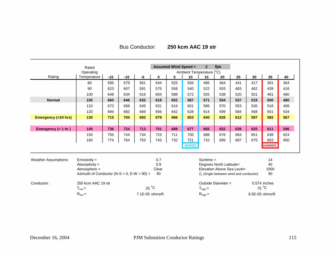
December 16, 2004 PJM Substation Conductor Ratings 115
Bus Conductor: 250 kcm AAC 19 str
2 fps
Rating -15 -10 -5 0 5 10 15 20 25 30 35 4080 595 579 561 544 525 506 485 464 441 417 391 36490 623 607 591 575 558 540 522 503 483 462 439 416100 648 634 619 604 588 572 555 538 520 501 481 460
Normal 105 660 646 632 618 602 587 571 554 537 519 500 480110 672 658 645 631 616 601 586 570 553 536 518 499120 694 682 669 656 642 628 614 599 584 568 551 534
Emergency (<24 hrs) 130 715 704 692 679 666 653 640 626 612 597 582 567
Emergency (< 1 hr ) 140 736 724 713 701 689 677 665 652 639 625 611 596150 755 744 734 723 711 700 688 676 663 651 638 624160 774 764 753 743 732 721 710 699 687 675 663 650
WINTER SUMMER
Weather Assumptions: Emissivity = 0.7 Suntime = 14Absorptivity = 0.9 Degrees North Latitude= 40Atmosphere = Clear Elevation Above Sea Level= 1000Azimuth of Conductor (N-S = 0, E-W = 90) = 90 Z1 (Angle between wind and conductor) 90
Conductor : 250 kcm AAC 19 str Outside Diameter = 0.574 inchesTlow = 25
oC Thigh = 75oC
Rlow = 7.1E-05 ohms/ft Rhigh = 8.5E-05 ohms/ft
Ambient Temperature (oC)Assumed Wind Speed =Rated
Operating Temperature

December 16, 2004 PJM Substation Conductor Ratings 116
Bus Conductor: 300 kcm AAC 19 str
2 fps
Rating -15 -10 -5 0 5 10 15 20 25 30 35 4080 668 650 630 610 589 567 545 520 495 468 439 40790 700 682 664 646 627 607 586 565 542 518 493 466100 728 712 696 679 661 643 624 604 584 563 540 517
Normal 105 742 727 711 694 677 660 642 623 603 583 562 539110 755 740 725 709 693 676 659 641 622 602 582 561120 781 767 752 738 722 707 691 674 657 639 620 601
Emergency (<24 hrs) 130 805 792 778 764 750 735 720 705 689 672 655 638
Emergency (< 1 hr ) 140 828 815 803 790 776 762 748 734 719 704 688 671150 850 838 826 814 801 788 775 761 747 733 718 703160 871 860 849 837 825 813 800 787 774 761 747 733
WINTER SUMMER
Weather Assumptions: Emissivity = 0.7 Suntime = 14Absorptivity = 0.9 Degrees North Latitude= 40Atmosphere = Clear Elevation Above Sea Level= 1000Azimuth of Conductor (N-S = 0, E-W = 90) = 90 Z1 (Angle between wind and conductor) 90
Conductor : 300 kcm AAC 19 str Outside Diameter = 0.629 inchesTlow = 25
oC Thigh = 75oC
Rlow = 5.9E-05 ohms/ft Rhigh = 7.1E-05 ohms/ft
Ambient Temperature (oC)Assumed Wind Speed =Rated
Operating Temperature

December 16, 2004 PJM Substation Conductor Ratings 117
Bus Conductor: 336.4 kcm AAC 19 str
2 fps
Rating -15 -10 -5 0 5 10 15 20 25 30 35 4080 719 699 678 656 634 610 585 559 532 503 471 43790 753 734 715 695 674 653 631 607 583 557 530 501100 784 767 749 730 711 692 671 650 628 605 581 556
Normal 105 799 782 765 747 729 710 691 670 649 627 604 580110 813 797 780 763 746 728 709 689 669 648 627 604120 841 825 810 794 778 761 743 726 707 688 668 647
Emergency (<24 hrs) 130 867 853 838 823 808 792 776 759 742 724 706 687
Emergency (< 1 hr ) 140 892 878 865 850 836 821 806 791 774 758 741 723150 916 903 890 877 863 849 835 820 805 790 774 757160 939 927 914 902 889 876 862 848 834 820 805 790
WINTER SUMMER
Weather Assumptions: Emissivity = 0.7 Suntime = 14Absorptivity = 0.9 Degrees North Latitude= 40Atmosphere = Clear Elevation Above Sea Level= 1000Azimuth of Conductor (N-S = 0, E-W = 90) = 90 Z1 (Angle between wind and conductor) 90
Conductor : 336.4 kcm AAC 19 str Outside Diameter = 0.666 inchesTlow = 25
oC Thigh = 75oC
Rlow = 5.3E-05 ohms/ft Rhigh = 6.3E-05 ohms/ft
Ambient Temperature (oC)Assumed Wind Speed =Rated
Operating Temperature

December 16, 2004 PJM Substation Conductor Ratings 118
Bus Conductor: 350 kcm AAC 19 str
2 fps
Rating -15 -10 -5 0 5 10 15 20 25 30 35 4080 737 716 695 673 650 625 600 573 545 515 483 44890 772 753 733 713 691 669 647 623 598 571 543 514100 804 786 768 749 730 709 689 667 644 621 596 570
Normal 105 819 802 784 766 747 728 708 687 666 643 620 595110 834 817 800 783 765 746 727 707 686 665 643 619120 862 847 831 814 798 780 763 744 725 705 685 664
Emergency (<24 hrs) 130 889 874 859 844 828 812 796 779 761 743 724 704
Emergency (< 1 hr ) 140 915 901 887 872 858 842 827 811 794 778 760 742150 939 926 913 899 885 871 856 841 826 810 794 777160 963 951 938 925 912 898 885 871 856 841 826 810
WINTER SUMMER
Weather Assumptions: Emissivity = 0.7 Suntime = 14Absorptivity = 0.9 Degrees North Latitude= 40Atmosphere = Clear Elevation Above Sea Level= 1000Azimuth of Conductor (N-S = 0, E-W = 90) = 90 Z1 (Angle between wind and conductor) 90
Conductor : 350 kcm AAC 19 str Outside Diameter = 0.679 inchesTlow = 25
oC Thigh = 75oC
Rlow = 5.1E-05 ohms/ft Rhigh = 6.1E-05 ohms/ft
Ambient Temperature (oC)Assumed Wind Speed =Rated
Operating Temperature

December 16, 2004 PJM Substation Conductor Ratings 119
Bus Conductor: 500 kcm AAC 19 str
2 fps
Rating -15 -10 -5 0 5 10 15 20 25 30 35 4080 924 898 871 843 814 783 751 717 682 644 603 55890 968 944 920 894 867 840 811 781 749 716 680 642100 1010 987 964 941 916 891 865 837 809 779 748 714
Normal 105 1029 1008 986 963 939 915 890 864 836 808 778 747110 1048 1027 1006 984 962 938 914 889 863 836 808 778120 1085 1065 1045 1025 1004 982 960 936 913 888 862 835
Emergency (<24 hrs) 130 1119 1101 1082 1063 1043 1023 1002 981 959 936 912 887
Emergency (< 1 hr ) 140 1153 1135 1118 1100 1081 1062 1042 1022 1002 980 958 936150 1184 1168 1151 1134 1117 1099 1081 1062 1042 1022 1002 981160 1215 1200 1184 1168 1151 1134 1117 1099 1081 1062 1043 1023
WINTER SUMMER
Weather Assumptions: Emissivity = 0.7 Suntime = 14Absorptivity = 0.9 Degrees North Latitude= 40Atmosphere = Clear Elevation Above Sea Level= 1000Azimuth of Conductor (N-S = 0, E-W = 90) = 90 Z1 (Angle between wind and conductor) 90
Conductor : 500 kcm AAC 19 str Outside Diameter = 0.811 inchesTlow = 25
oC Thigh = 75oC
Rlow = 3.6E-05 ohms/ft Rhigh = 4.3E-05 ohms/ft
Ambient Temperature (oC)Assumed Wind Speed =Rated
Operating Temperature

December 16, 2004 PJM Substation Conductor Ratings 120
Bus Conductor: 556.5 kcm AAC 37 str
2 fps
Rating -15 -10 -5 0 5 10 15 20 25 30 35 4080 989 961 933 903 871 838 804 768 729 688 644 59790 1037 1012 985 958 929 899 868 836 802 766 728 688100 1082 1058 1033 1008 982 955 926 897 866 834 801 765
Normal 105 1103 1080 1056 1032 1007 981 954 926 896 866 834 800110 1124 1101 1078 1055 1031 1006 980 953 925 896 865 834120 1163 1142 1121 1099 1076 1053 1029 1004 978 952 924 895
Emergency (<24 hrs) 130 1200 1181 1161 1140 1119 1097 1075 1052 1028 1003 978 952
Emergency (< 1 hr ) 140 1236 1218 1199 1180 1160 1139 1118 1097 1075 1052 1028 1004150 1271 1253 1235 1217 1198 1179 1160 1139 1119 1097 1075 1053160 1304 1287 1271 1253 1235 1217 1199 1180 1160 1140 1120 1098
WINTER SUMMER
Weather Assumptions: Emissivity = 0.7 Suntime = 14Absorptivity = 0.9 Degrees North Latitude= 40Atmosphere = Clear Elevation Above Sea Level= 1000Azimuth of Conductor (N-S = 0, E-W = 90) = 90 Z1 (Angle between wind and conductor) 90
Conductor : 556.5 kcm AAC 37 str Outside Diameter = 0.858 inchesTlow = 25
oC Thigh = 75oC
Rlow = 3.2E-05 ohms/ft Rhigh = 3.8E-05 ohms/ft
Ambient Temperature (oC)Assumed Wind Speed =Rated
Operating Temperature

December 16, 2004 PJM Substation Conductor Ratings 121
Bus Conductor: 795 kcm AAC 37 str
2 fps
Rating -15 -10 -5 0 5 10 15 20 25 30 35 4080 1238 1203 1167 1129 1090 1049 1005 959 911 859 803 74290 1300 1268 1235 1200 1164 1127 1088 1047 1004 959 910 859100 1358 1328 1297 1265 1232 1198 1162 1125 1087 1046 1004 959
Normal 105 1385 1356 1326 1296 1264 1231 1197 1162 1125 1087 1046 1004110 1412 1384 1355 1325 1295 1263 1231 1197 1162 1125 1087 1047120 1463 1437 1410 1382 1354 1325 1294 1263 1231 1197 1162 1126
Emergency (<24 hrs) 130 1511 1487 1462 1436 1409 1382 1354 1325 1295 1264 1232 1198
Emergency (< 1 hr ) 140 1558 1535 1511 1487 1462 1436 1410 1383 1355 1326 1296 1266150 1603 1581 1558 1535 1512 1488 1463 1438 1412 1385 1357 1329160 1646 1625 1604 1582 1560 1537 1514 1490 1466 1441 1415 1388
WINTER SUMMER
Weather Assumptions: Emissivity = 0.7 Suntime = 14Absorptivity = 0.9 Degrees North Latitude= 40Atmosphere = Clear Elevation Above Sea Level= 1000Azimuth of Conductor (N-S = 0, E-W = 90) = 90 Z1 (Angle between wind and conductor) 90
Conductor : 795 kcm AAC 37 str Outside Diameter = 1.026 inchesTlow = 25
oC Thigh = 75oC
Rlow = 2.3E-05 ohms/ft Rhigh = 2.7E-05 ohms/ft
Ambient Temperature (oC)Assumed Wind Speed =Rated
Operating Temperature
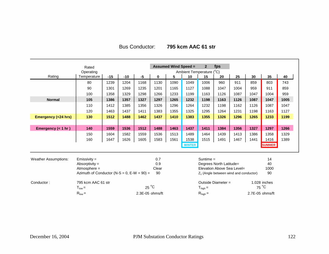
December 16, 2004 PJM Substation Conductor Ratings 122
Bus Conductor: 795 kcm AAC 61 str
2 fps
Rating -15 -10 -5 0 5 10 15 20 25 30 35 4080 1239 1204 1168 1130 1090 1049 1006 960 911 859 803 74390 1301 1269 1235 1201 1165 1127 1088 1047 1004 959 911 859100 1358 1329 1298 1266 1233 1199 1163 1126 1087 1047 1004 959
Normal 105 1386 1357 1327 1297 1265 1232 1198 1163 1126 1087 1047 1005110 1412 1385 1356 1326 1296 1264 1232 1198 1162 1126 1087 1047120 1463 1437 1411 1383 1355 1325 1295 1264 1231 1198 1163 1127
Emergency (<24 hrs) 130 1512 1488 1462 1437 1410 1383 1355 1326 1296 1265 1233 1199
Emergency (< 1 hr ) 140 1559 1536 1512 1488 1463 1437 1411 1384 1356 1327 1297 1266150 1604 1582 1559 1536 1513 1489 1464 1439 1413 1386 1358 1329160 1647 1626 1605 1583 1561 1538 1515 1491 1467 1441 1416 1389
WINTER SUMMER
Weather Assumptions: Emissivity = 0.7 Suntime = 14Absorptivity = 0.9 Degrees North Latitude= 40Atmosphere = Clear Elevation Above Sea Level= 1000Azimuth of Conductor (N-S = 0, E-W = 90) = 90 Z1 (Angle between wind and conductor) 90
Conductor : 795 kcm AAC 61 str Outside Diameter = 1.028 inchesTlow = 25
oC Thigh = 75oC
Rlow = 2.3E-05 ohms/ft Rhigh = 2.7E-05 ohms/ft
Ambient Temperature (oC)Assumed Wind Speed =Rated
Operating Temperature

December 16, 2004 PJM Substation Conductor Ratings 123
Bus Conductor: 1000 kcm AAC 37 str
2 fps
Rating -15 -10 -5 0 5 10 15 20 25 30 35 4080 1429 1388 1346 1303 1257 1209 1159 1105 1049 988 923 85390 1502 1464 1426 1386 1344 1301 1256 1208 1158 1106 1050 990100 1569 1535 1499 1462 1424 1385 1343 1301 1256 1209 1159 1107
Normal 105 1602 1568 1534 1499 1462 1424 1385 1344 1301 1256 1209 1160110 1633 1601 1568 1534 1498 1462 1424 1385 1344 1302 1257 1210120 1694 1663 1632 1601 1568 1534 1499 1463 1425 1386 1346 1304
Emergency (<24 hrs) 130 1751 1723 1694 1664 1633 1602 1569 1535 1501 1465 1428 1389
Emergency (< 1 hr ) 140 1806 1780 1752 1724 1695 1666 1635 1604 1572 1538 1504 1468150 1859 1834 1808 1782 1755 1727 1698 1669 1639 1608 1576 1543160 1911 1887 1862 1837 1812 1786 1759 1731 1703 1674 1644 1613
WINTER SUMMER
Weather Assumptions: Emissivity = 0.7 Suntime = 14Absorptivity = 0.9 Degrees North Latitude= 40Atmosphere = Clear Elevation Above Sea Level= 1000Azimuth of Conductor (N-S = 0, E-W = 90) = 90 Z1 (Angle between wind and conductor) 90
Conductor : 1000 kcm AAC 37 str Outside Diameter = 1.15 inchesTlow = 25
oC Thigh = 75oC
Rlow = 1.8E-05 ohms/ft Rhigh = 2.2E-05 ohms/ft
Ambient Temperature (oC)Assumed Wind Speed =Rated
Operating Temperature

December 16, 2004 PJM Substation Conductor Ratings 124
Bus Conductor: 1033.5 kcm AAC 61 str
2 fps
Rating -15 -10 -5 0 5 10 15 20 25 30 35 4080 1459 1418 1375 1330 1283 1234 1183 1128 1071 1009 942 87090 1534 1496 1456 1415 1373 1329 1282 1234 1183 1129 1072 1011100 1603 1568 1531 1494 1455 1414 1372 1328 1283 1235 1184 1131
Normal 105 1636 1602 1567 1531 1493 1455 1414 1373 1329 1283 1235 1185110 1668 1636 1602 1567 1531 1493 1455 1415 1373 1330 1284 1237120 1730 1700 1668 1635 1602 1567 1532 1495 1456 1417 1375 1332
Emergency (<24 hrs) 130 1789 1760 1731 1700 1669 1637 1603 1569 1534 1497 1459 1420
Emergency (< 1 hr ) 140 1846 1819 1791 1762 1733 1702 1671 1639 1606 1572 1537 1501150 1901 1875 1848 1821 1794 1765 1736 1706 1675 1643 1611 1577160 1953 1929 1904 1878 1852 1825 1798 1770 1741 1711 1680 1649
WINTER SUMMER
Weather Assumptions: Emissivity = 0.7 Suntime = 14Absorptivity = 0.9 Degrees North Latitude= 40Atmosphere = Clear Elevation Above Sea Level= 1000Azimuth of Conductor (N-S = 0, E-W = 90) = 90 Z1 (Angle between wind and conductor) 90
Conductor : 1033.5 kcm AAC 61 str Outside Diameter = 1.172 inchesTlow = 25
oC Thigh = 75oC
Rlow = 1.8E-05 ohms/ft Rhigh = 2.1E-05 ohms/ft
Ambient Temperature (oC)Assumed Wind Speed =Rated
Operating Temperature

December 16, 2004 PJM Substation Conductor Ratings 125
Bus Conductor: 1510.5 kcm AAC 61 str
2 fps
Rating -15 -10 -5 0 5 10 15 20 25 30 35 4080 1838 1785 1731 1674 1615 1553 1487 1418 1344 1265 1180 108790 1936 1887 1838 1786 1732 1676 1617 1555 1490 1422 1349 1271100 2027 1982 1936 1889 1839 1788 1735 1679 1621 1560 1495 1427
Normal 105 2071 2028 1983 1938 1890 1841 1790 1737 1681 1623 1562 1498110 2113 2072 2029 1985 1939 1892 1843 1792 1739 1684 1626 1565120 2195 2156 2116 2075 2033 1989 1944 1897 1848 1798 1745 1690
Emergency (<24 hrs) 130 2274 2237 2199 2161 2121 2080 2038 1995 1950 1903 1855 1805
Emergency (< 1 hr ) 140 2349 2314 2279 2243 2205 2167 2128 2087 2045 2002 1957 1911150 2421 2389 2355 2321 2286 2250 2213 2175 2136 2096 2054 2011160 2492 2461 2429 2397 2364 2330 2295 2259 2223 2185 2146 2106
WINTER SUMMER
Weather Assumptions: Emissivity = 0.7 Suntime = 14Absorptivity = 0.9 Degrees North Latitude= 40Atmosphere = Clear Elevation Above Sea Level= 1000Azimuth of Conductor (N-S = 0, E-W = 90) = 90 Z1 (Angle between wind and conductor) 90
Conductor : 1510.5 kcm AAC 61 str Outside Diameter = 1.417 inchesTlow = 25
oC Thigh = 75oC
Rlow = 1.3E-05 ohms/ft Rhigh = 1.5E-05 ohms/ft
Ambient Temperature (oC)Assumed Wind Speed =Rated
Operating Temperature

December 16, 2004 PJM Substation Conductor Ratings 126
Bus Conductor: 1590 kcm AAC 61 str
2 fps
Rating -15 -10 -5 0 5 10 15 20 25 30 35 4080 1895 1841 1785 1726 1665 1601 1533 1461 1385 1304 1216 112090 1996 1947 1895 1842 1786 1728 1668 1604 1537 1466 1391 1310100 2092 2045 1998 1949 1898 1845 1790 1732 1672 1609 1542 1472
Normal 105 2137 2093 2047 1999 1950 1900 1847 1792 1735 1675 1612 1546110 2181 2138 2094 2049 2001 1953 1902 1850 1795 1738 1678 1615120 2267 2226 2185 2143 2099 2054 2007 1958 1908 1856 1802 1745
Emergency (<24 hrs) 130 2348 2310 2272 2232 2191 2149 2105 2060 2014 1966 1916 1864
Emergency (< 1 hr ) 140 2427 2391 2354 2317 2279 2239 2198 2157 2113 2069 2023 1975150 2502 2469 2434 2399 2363 2326 2287 2248 2208 2166 2123 2079160 2576 2544 2511 2478 2444 2409 2373 2336 2298 2259 2219 2177
WINTER SUMMER
Weather Assumptions: Emissivity = 0.7 Suntime = 14Absorptivity = 0.9 Degrees North Latitude= 40Atmosphere = Clear Elevation Above Sea Level= 1000Azimuth of Conductor (N-S = 0, E-W = 90) = 90 Z1 (Angle between wind and conductor) 90
Conductor : 1590 kcm AAC 61 str Outside Diameter = 1.454 inchesTlow = 25
oC Thigh = 75oC
Rlow = 1.2E-05 ohms/ft Rhigh = 1.4E-05 ohms/ft
Ambient Temperature (oC)Assumed Wind Speed =Rated
Operating Temperature

December 16, 2004 PJM Substation Conductor Ratings 127
Bus Conductor: 2000 kcm AAC 127 str
2 fps
Rating -15 -10 -5 0 5 10 15 20 25 30 35 4080 2210 2146 2081 2012 1941 1865 1786 1702 1612 1516 1413 129990 2340 2282 2222 2159 2094 2025 1954 1879 1800 1716 1627 1532100 2464 2410 2354 2296 2236 2173 2108 2040 1969 1894 1816 1732
Normal 105 2524 2471 2417 2361 2303 2243 2181 2116 2048 1977 1903 1824110 2582 2531 2479 2425 2369 2311 2252 2189 2124 2057 1986 1911120 2695 2647 2598 2548 2496 2442 2386 2329 2269 2207 2142 2075
Emergency (<24 hrs) 130 2804 2759 2713 2665 2616 2566 2514 2461 2405 2348 2288 2226
Emergency (< 1 hr ) 140 2909 2866 2823 2778 2732 2685 2637 2586 2535 2481 2426 2369150 3011 2971 2930 2888 2844 2800 2754 2707 2658 2608 2557 2503160 3111 3073 3034 2994 2953 2911 2867 2823 2777 2730 2682 2632
WINTER SUMMER
Weather Assumptions: Emissivity = 0.7 Suntime = 14Absorptivity = 0.9 Degrees North Latitude= 40Atmosphere = Clear Elevation Above Sea Level= 1000Azimuth of Conductor (N-S = 0, E-W = 90) = 90 Z1 (Angle between wind and conductor) 90
Conductor : 2000 kcm AAC 127 str Outside Diameter = 1.63 inchesTlow = 25
oC Thigh = 75oC
Rlow = 0.00001 ohms/ft Rhigh = 1.1E-05 ohms/ft
Ambient Temperature (oC)Assumed Wind Speed =Rated
Operating Temperature
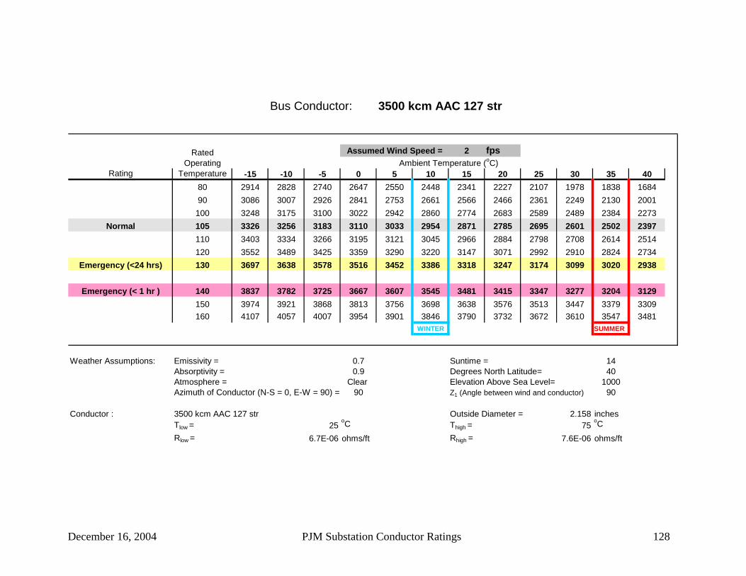
December 16, 2004 PJM Substation Conductor Ratings 128
Bus Conductor: 3500 kcm AAC 127 str
2 fps
Rating -15 -10 -5 0 5 10 15 20 25 30 35 4080 2914 2828 2740 2647 2550 2448 2341 2227 2107 1978 1838 168490 3086 3007 2926 2841 2753 2661 2566 2466 2361 2249 2130 2001100 3248 3175 3100 3022 2942 2860 2774 2683 2589 2489 2384 2273
Normal 105 3326 3256 3183 3110 3033 2954 2871 2785 2695 2601 2502 2397110 3403 3334 3266 3195 3121 3045 2966 2884 2798 2708 2614 2514120 3552 3489 3425 3359 3290 3220 3147 3071 2992 2910 2824 2734
Emergency (<24 hrs) 130 3697 3638 3578 3516 3452 3386 3318 3247 3174 3099 3020 2938
Emergency (< 1 hr ) 140 3837 3782 3725 3667 3607 3545 3481 3415 3347 3277 3204 3129150 3974 3921 3868 3813 3756 3698 3638 3576 3513 3447 3379 3309160 4107 4057 4007 3954 3901 3846 3790 3732 3672 3610 3547 3481
WINTER SUMMER
Weather Assumptions: Emissivity = 0.7 Suntime = 14Absorptivity = 0.9 Degrees North Latitude= 40Atmosphere = Clear Elevation Above Sea Level= 1000Azimuth of Conductor (N-S = 0, E-W = 90) = 90 Z1 (Angle between wind and conductor) 90
Conductor : 3500 kcm AAC 127 str Outside Diameter = 2.158 inchesTlow = 25
oC Thigh = 75oC
Rlow = 6.7E-06 ohms/ft Rhigh = 7.6E-06 ohms/ft
Ambient Temperature (oC)Assumed Wind Speed =Rated
Operating Temperature
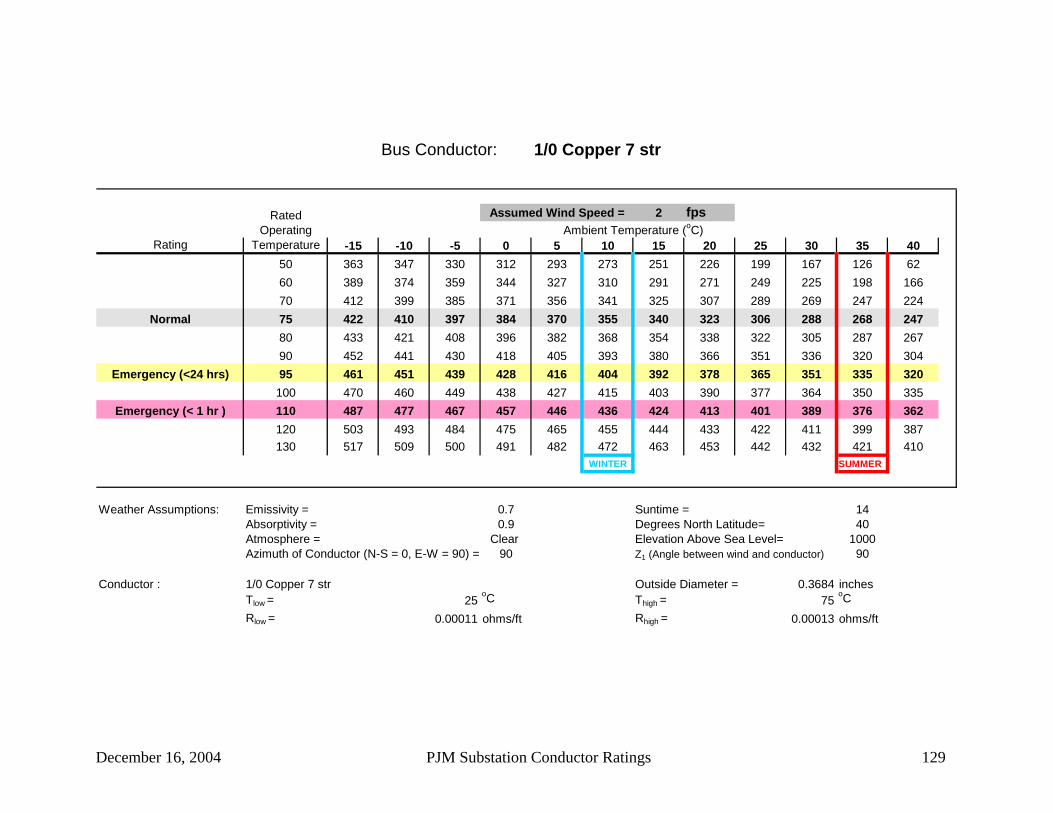
December 16, 2004 PJM Substation Conductor Ratings 129
Bus Conductor: 1/0 Copper 7 str
2 fps
Rating -15 -10 -5 0 5 10 15 20 25 30 35 4050 363 347 330 312 293 273 251 226 199 167 126 6260 389 374 359 344 327 310 291 271 249 225 198 16670 412 399 385 371 356 341 325 307 289 269 247 224
Normal 75 422 410 397 384 370 355 340 323 306 288 268 24780 433 421 408 396 382 368 354 338 322 305 287 26790 452 441 430 418 405 393 380 366 351 336 320 304
Emergency (<24 hrs) 95 461 451 439 428 416 404 392 378 365 351 335 320100 470 460 449 438 427 415 403 390 377 364 350 335
Emergency (< 1 hr ) 110 487 477 467 457 446 436 424 413 401 389 376 362120 503 493 484 475 465 455 444 433 422 411 399 387130 517 509 500 491 482 472 463 453 442 432 421 410
WINTER SUMMER
Weather Assumptions: Emissivity = 0.7 Suntime = 14Absorptivity = 0.9 Degrees North Latitude= 40Atmosphere = Clear Elevation Above Sea Level= 1000Azimuth of Conductor (N-S = 0, E-W = 90) = 90 Z1 (Angle between wind and conductor) 90
Conductor : 1/0 Copper 7 str Outside Diameter = 0.3684 inchesTlow = 25
oC Thigh = 75oC
Rlow = 0.00011 ohms/ft Rhigh = 0.00013 ohms/ft
Ambient Temperature (oC)Assumed Wind Speed =Rated
Operating Temperature

December 16, 2004 PJM Substation Conductor Ratings 130
Bus Conductor: 2/0 Copper 7 str
2 fps
Rating -15 -10 -5 0 5 10 15 20 25 30 35 4050 419 401 381 361 339 315 289 260 228 190 142 6260 450 433 416 397 378 358 336 313 287 259 227 18970 477 462 446 429 412 394 375 355 334 311 285 258
Normal 75 489 475 460 444 428 411 393 374 354 333 310 28580 501 487 473 458 443 426 410 392 373 353 332 30990 524 511 498 484 470 455 440 424 407 390 371 351
Emergency (<24 hrs) 95 535 522 510 496 483 469 454 439 423 406 389 370100 545 533 521 508 495 481 467 453 438 422 405 388
Emergency (< 1 hr ) 110 565 554 542 530 518 505 492 479 465 451 436 420120 583 573 562 551 539 528 516 503 490 477 463 449130 601 591 581 570 560 549 537 526 514 501 489 476
WINTER SUMMER
Weather Assumptions: Emissivity = 0.7 Suntime = 14Absorptivity = 0.9 Degrees North Latitude= 40Atmosphere = Clear Elevation Above Sea Level= 1000Azimuth of Conductor (N-S = 0, E-W = 90) = 90 Z1 (Angle between wind and conductor) 90
Conductor : 2/0 Copper 7 str Outside Diameter = 0.4137 inchesTlow = 25
oC Thigh = 75oC
Rlow = 8.4E-05 ohms/ft Rhigh = 1E-04 ohms/ft
Ambient Temperature (oC)Assumed Wind Speed =Rated
Operating Temperature

December 16, 2004 PJM Substation Conductor Ratings 131
Bus Conductor: 4/0 Copper 7 str
2 fps
Rating -15 -10 -5 0 5 10 15 20 25 30 35 4050 560 535 508 480 450 418 383 343 299 246 177 4460 601 579 555 531 505 477 447 416 381 342 298 24670 639 618 597 575 552 527 502 474 445 414 379 341
Normal 75 656 636 616 595 573 550 526 500 473 444 413 37980 673 654 634 614 593 571 549 524 499 472 443 41290 704 686 669 650 631 611 590 569 546 522 497 470
Emergency (<24 hrs) 95 719 702 685 667 648 629 610 589 567 545 521 496100 733 717 700 683 665 647 628 608 588 566 544 520
Emergency (< 1 hr ) 110 760 745 729 713 697 680 663 644 626 606 586 565120 785 771 757 742 727 711 695 678 660 643 624 605130 810 796 783 769 754 740 724 709 693 676 659 641
WINTER SUMMER
Weather Assumptions: Emissivity = 0.7 Suntime = 14Absorptivity = 0.9 Degrees North Latitude= 40Atmosphere = Clear Elevation Above Sea Level= 1000Azimuth of Conductor (N-S = 0, E-W = 90) = 90 Z1 (Angle between wind and conductor) 90
Conductor : 4/0 Copper 7 str Outside Diameter = 0.5217 inchesTlow = 25
oC Thigh = 75oC
Rlow = 5.3E-05 ohms/ft Rhigh = 6.3E-05 ohms/ft
Ambient Temperature (oC)Assumed Wind Speed =Rated
Operating Temperature

December 16, 2004 PJM Substation Conductor Ratings 132
Bus Conductor: 4/0 Copper 19 str
2 fps
Rating -15 -10 -5 0 5 10 15 20 25 30 35 4050 561 536 510 482 452 419 384 344 299 246 177 4160 603 581 557 532 506 478 449 417 382 343 299 24670 641 620 599 577 553 529 503 476 446 415 380 342
Normal 75 658 638 618 597 575 552 527 502 474 445 414 37980 675 656 636 616 595 573 550 526 501 473 444 41390 706 689 671 652 633 613 592 570 548 524 499 472
Emergency (<24 hrs) 95 721 704 687 669 650 631 611 591 569 547 523 498100 735 719 702 685 667 649 630 610 590 568 546 522
Emergency (< 1 hr ) 110 762 747 732 716 699 682 665 646 628 608 588 567120 788 774 759 744 729 713 697 680 663 645 626 607130 812 799 785 771 757 742 727 711 695 678 661 643
WINTER SUMMER
Weather Assumptions: Emissivity = 0.7 Suntime = 14Absorptivity = 0.9 Degrees North Latitude= 40Atmosphere = Clear Elevation Above Sea Level= 1000Azimuth of Conductor (N-S = 0, E-W = 90) = 90 Z1 (Angle between wind and conductor) 90
Conductor : 4/0 Copper 19 str Outside Diameter = 0.5275 inchesTlow = 25
oC Thigh = 75oC
Rlow = 5.3E-05 ohms/ft Rhigh = 6.3E-05 ohms/ft
Ambient Temperature (oC)Assumed Wind Speed =Rated
Operating Temperature

December 16, 2004 PJM Substation Conductor Ratings 133
Bus Conductor: 250 kcm Copper 19 str
2 fps
Rating -15 -10 -5 0 5 10 15 20 25 30 35 4050 623 595 565 534 500 464 424 380 330 269 190 #NUM!60 670 644 618 591 561 530 497 461 422 379 329 27070 711 689 665 640 614 587 558 528 495 459 421 378
Normal 75 731 709 687 663 638 613 585 557 526 494 459 42080 750 729 707 685 661 637 611 584 556 525 493 45890 785 765 745 725 703 681 658 634 609 582 554 524
Emergency (<24 hrs) 95 801 783 764 744 723 702 680 657 633 607 581 553100 817 799 781 762 742 722 701 679 656 632 607 580
Emergency (< 1 hr ) 110 848 831 814 796 778 759 739 719 698 676 654 630120 877 861 845 828 811 794 775 757 737 717 697 675130 904 889 874 858 842 826 809 792 774 755 736 716
WINTER SUMMER
Weather Assumptions: Emissivity = 0.7 Suntime = 14Absorptivity = 0.9 Degrees North Latitude= 40Atmosphere = Clear Elevation Above Sea Level= 1000Azimuth of Conductor (N-S = 0, E-W = 90) = 90 Z1 (Angle between wind and conductor) 90
Conductor : 250 kcm Copper 19 str Outside Diameter = 0.5735 inchesTlow = 25
oC Thigh = 75oC
Rlow = 4.5E-05 ohms/ft Rhigh = 5.3E-05 ohms/ft
Ambient Temperature (oC)Assumed Wind Speed =Rated
Operating Temperature

December 16, 2004 PJM Substation Conductor Ratings 134
Bus Conductor: 350 kcm Copper 19 str
2 fps
Rating -15 -10 -5 0 5 10 15 20 25 30 35 4050 767 732 695 656 614 569 519 463 399 323 219 #NUM!60 826 795 762 728 691 653 611 566 517 462 399 32470 879 851 821 790 758 724 688 650 609 565 516 462
Normal 75 904 877 848 819 789 756 723 687 649 608 564 51680 927 901 874 846 817 787 755 721 686 648 607 56490 972 948 923 897 871 843 814 784 753 719 684 647
Emergency (<24 hrs) 95 993 970 946 921 896 869 842 813 783 752 719 684100 1013 991 968 944 919 894 868 840 812 782 751 718
Emergency (< 1 hr ) 110 1052 1031 1009 987 965 941 917 892 866 839 811 781120 1088 1069 1049 1028 1007 985 963 939 915 890 865 838130 1123 1105 1086 1066 1047 1026 1005 984 961 938 914 890
WINTER SUMMER
Weather Assumptions: Emissivity = 0.7 Suntime = 14Absorptivity = 0.9 Degrees North Latitude= 40Atmosphere = Clear Elevation Above Sea Level= 1000Azimuth of Conductor (N-S = 0, E-W = 90) = 90 Z1 (Angle between wind and conductor) 90
Conductor : 350 kcm Copper 19 str Outside Diameter = 0.6785 inchesTlow = 25
oC Thigh = 75oC
Rlow = 3.2E-05 ohms/ft Rhigh = 3.8E-05 ohms/ft
Ambient Temperature (oC)Assumed Wind Speed =Rated
Operating Temperature

December 16, 2004 PJM Substation Conductor Ratings 135
Bus Conductor: 350 kcm Copper 37 str
2 fps
Rating -15 -10 -5 0 5 10 15 20 25 30 35 4050 768 733 696 657 615 569 519 464 400 323 219 #NUM!60 827 796 763 728 692 653 612 567 518 463 400 32470 880 852 822 791 759 725 689 651 610 565 517 462
Normal 75 905 877 849 820 789 757 723 688 650 609 565 51680 928 902 875 847 818 788 756 722 686 649 608 56490 973 949 924 898 872 844 815 785 753 720 685 647
Emergency (<24 hrs) 95 994 971 947 922 897 870 843 814 784 752 719 684100 1014 992 969 945 920 895 869 841 813 783 752 719
Emergency (< 1 hr ) 110 1053 1032 1011 988 966 942 918 893 867 840 811 782120 1090 1070 1050 1029 1008 986 964 940 916 891 866 839130 1124 1106 1087 1068 1048 1027 1006 985 962 939 916 891
WINTER SUMMER
Weather Assumptions: Emissivity = 0.7 Suntime = 14Absorptivity = 0.9 Degrees North Latitude= 40Atmosphere = Clear Elevation Above Sea Level= 1000Azimuth of Conductor (N-S = 0, E-W = 90) = 90 Z1 (Angle between wind and conductor) 90
Conductor : 350 kcm Copper 37 str Outside Diameter = 0.6811 inchesTlow = 25
oC Thigh = 75oC
Rlow = 3.2E-05 ohms/ft Rhigh = 3.8E-05 ohms/ft
Ambient Temperature (oC)Assumed Wind Speed =Rated
Operating Temperature

December 16, 2004 PJM Substation Conductor Ratings 136
Bus Conductor: 500 kcm Copper 19 str
2 fps
Rating -15 -10 -5 0 5 10 15 20 25 30 35 4050 955 911 865 815 762 704 641 570 488 388 249 #NUM!60 1031 991 950 907 861 812 759 702 640 570 489 39170 1098 1063 1026 987 946 903 858 810 758 701 640 570
Normal 75 1130 1096 1061 1024 985 945 902 857 809 757 701 64080 1160 1128 1094 1059 1022 984 943 901 856 808 757 70190 1217 1187 1156 1124 1090 1056 1019 981 942 900 855 808
Emergency (<24 hrs) 95 1244 1215 1185 1154 1122 1089 1055 1018 981 941 899 855100 1270 1243 1214 1184 1153 1121 1088 1054 1018 980 941 899
Emergency (< 1 hr ) 110 1320 1294 1267 1240 1211 1182 1151 1120 1087 1053 1017 980120 1368 1343 1318 1292 1266 1238 1210 1181 1151 1119 1087 1053130 1413 1390 1366 1342 1317 1291 1265 1238 1210 1181 1151 1120
WINTER SUMMER
Weather Assumptions: Emissivity = 0.7 Suntime = 14Absorptivity = 0.9 Degrees North Latitude= 40Atmosphere = Clear Elevation Above Sea Level= 1000Azimuth of Conductor (N-S = 0, E-W = 90) = 90 Z1 (Angle between wind and conductor) 90
Conductor : 500 kcm Copper 19 str Outside Diameter = 0.811 inchesTlow = 25
oC Thigh = 75oC
Rlow = 2.3E-05 ohms/ft Rhigh = 2.7E-05 ohms/ft
Ambient Temperature (oC)Assumed Wind Speed =Rated
Operating Temperature

December 16, 2004 PJM Substation Conductor Ratings 137
Bus Conductor: 500 kcm Copper 37 str
2 fps
Rating -15 -10 -5 0 5 10 15 20 25 30 35 4050 956 912 865 816 762 705 641 570 488 388 249 #NUM!60 1031 992 951 907 861 812 760 703 640 570 489 39170 1099 1064 1026 988 947 904 859 810 758 702 640 571
Normal 75 1131 1097 1061 1024 986 945 903 858 809 758 702 64080 1161 1129 1095 1059 1023 984 944 902 857 809 757 70290 1218 1188 1157 1125 1091 1057 1020 982 942 900 856 808
Emergency (<24 hrs) 95 1245 1216 1186 1155 1123 1090 1055 1019 982 942 900 856100 1272 1244 1215 1185 1154 1122 1089 1055 1019 981 942 900
Emergency (< 1 hr ) 110 1322 1295 1269 1241 1212 1183 1152 1121 1088 1054 1018 981120 1369 1344 1319 1293 1267 1239 1211 1182 1152 1120 1088 1054130 1414 1391 1367 1343 1318 1292 1266 1239 1211 1182 1152 1121
WINTER SUMMER
Weather Assumptions: Emissivity = 0.7 Suntime = 14Absorptivity = 0.9 Degrees North Latitude= 40Atmosphere = Clear Elevation Above Sea Level= 1000Azimuth of Conductor (N-S = 0, E-W = 90) = 90 Z1 (Angle between wind and conductor) 90
Conductor : 500 kcm Copper 37 str Outside Diameter = 0.8134 inchesTlow = 25
oC Thigh = 75oC
Rlow = 2.3E-05 ohms/ft Rhigh = 2.7E-05 ohms/ft
Ambient Temperature (oC)Assumed Wind Speed =Rated
Operating Temperature

December 16, 2004 PJM Substation Conductor Ratings 138
Bus Conductor: 750 kcm Copper 37 str
2 fps
Rating -15 -10 -5 0 5 10 15 20 25 30 35 4050 1219 1162 1102 1037 968 892 809 716 606 471 274 #NUM!60 1319 1268 1215 1159 1099 1035 967 892 810 718 610 47870 1409 1363 1315 1265 1212 1157 1097 1034 967 893 812 721
Normal 75 1451 1407 1362 1314 1264 1211 1156 1097 1035 967 894 81380 1492 1449 1406 1360 1313 1263 1211 1156 1097 1035 968 89590 1568 1529 1489 1447 1404 1359 1312 1263 1211 1156 1098 1036
Emergency (<24 hrs) 95 1604 1566 1528 1488 1446 1403 1359 1312 1263 1211 1157 1099100 1639 1603 1566 1527 1487 1446 1403 1359 1312 1263 1212 1158
Emergency (< 1 hr ) 110 1706 1672 1637 1602 1565 1527 1487 1446 1404 1360 1313 1265120 1769 1738 1705 1672 1638 1602 1566 1528 1489 1448 1406 1362130 1830 1800 1770 1738 1706 1673 1639 1604 1568 1530 1491 1451
WINTER SUMMER
Weather Assumptions: Emissivity = 0.7 Suntime = 14Absorptivity = 0.9 Degrees North Latitude= 40Atmosphere = Clear Elevation Above Sea Level= 1000Azimuth of Conductor (N-S = 0, E-W = 90) = 90 Z1 (Angle between wind and conductor) 90
Conductor : 750 kcm Copper 37 str Outside Diameter = 0.9968 inchesTlow = 25
oC Thigh = 75oC
Rlow = 1.6E-05 ohms/ft Rhigh = 1.8E-05 ohms/ft
Ambient Temperature (oC)Assumed Wind Speed =Rated
Operating Temperature

December 16, 2004 PJM Substation Conductor Ratings 139
Bus Conductor: 750 kcm Copper 61 str
2 fps
Rating -15 -10 -5 0 5 10 15 20 25 30 35 4050 1219 1162 1102 1037 968 893 809 716 607 471 274 #NUM!60 1320 1269 1215 1159 1099 1036 967 892 810 718 610 47870 1410 1364 1316 1265 1213 1157 1098 1035 967 893 812 721
Normal 75 1452 1408 1362 1314 1264 1212 1156 1098 1035 967 894 81380 1492 1450 1406 1361 1313 1264 1211 1156 1098 1035 968 89590 1568 1529 1489 1448 1404 1359 1312 1263 1211 1157 1099 1037
Emergency (<24 hrs) 95 1604 1567 1528 1488 1447 1404 1359 1312 1263 1212 1157 1099100 1639 1603 1566 1528 1488 1447 1404 1359 1312 1264 1212 1158
Emergency (< 1 hr ) 110 1706 1673 1638 1602 1565 1527 1488 1447 1405 1360 1314 1265120 1770 1738 1706 1672 1638 1603 1566 1528 1489 1449 1406 1363130 1831 1801 1770 1739 1707 1674 1640 1605 1568 1531 1492 1452
WINTER SUMMER
Weather Assumptions: Emissivity = 0.7 Suntime = 14Absorptivity = 0.9 Degrees North Latitude= 40Atmosphere = Clear Elevation Above Sea Level= 1000Azimuth of Conductor (N-S = 0, E-W = 90) = 90 Z1 (Angle between wind and conductor) 90
Conductor : 750 kcm Copper 61 str Outside Diameter = 0.9981 inchesTlow = 25
oC Thigh = 75oC
Rlow = 1.6E-05 ohms/ft Rhigh = 1.8E-05 ohms/ft
Ambient Temperature (oC)Assumed Wind Speed =Rated
Operating Temperature

December 16, 2004 PJM Substation Conductor Ratings 140
Bus Conductor: 1000 kcm Copper 37 str
2 fps
Rating -15 -10 -5 0 5 10 15 20 25 30 35 4050 1440 1372 1299 1222 1139 1048 948 835 702 535 278 #NUM!60 1562 1501 1437 1370 1298 1222 1140 1050 951 839 708 54570 1671 1617 1559 1499 1436 1370 1299 1223 1142 1053 955 845
Normal 75 1723 1670 1616 1559 1499 1436 1370 1300 1224 1143 1055 95880 1772 1722 1670 1615 1559 1499 1437 1371 1301 1226 1145 105790 1865 1819 1771 1721 1670 1616 1560 1501 1439 1373 1304 1230
Emergency (<24 hrs) 95 1910 1865 1819 1771 1722 1670 1617 1561 1502 1440 1375 1306100 1952 1909 1865 1819 1772 1723 1671 1618 1562 1504 1442 1377
Emergency (< 1 hr ) 110 2035 1995 1953 1911 1867 1821 1774 1725 1675 1622 1566 1508120 2113 2075 2037 1997 1956 1914 1870 1825 1778 1730 1679 1626130 2187 2152 2116 2078 2040 2001 1960 1918 1875 1830 1783 1735
WINTER SUMMER
Weather Assumptions: Emissivity = 0.7 Suntime = 14Absorptivity = 0.9 Degrees North Latitude= 40Atmosphere = Clear Elevation Above Sea Level= 1000Azimuth of Conductor (N-S = 0, E-W = 90) = 90 Z1 (Angle between wind and conductor) 90
Conductor : 1000 kcm Copper 37 str Outside Diameter = 1.1508 inchesTlow = 25
oC Thigh = 75oC
Rlow = 1.2E-05 ohms/ft Rhigh = 1.4E-05 ohms/ft
Ambient Temperature (oC)Assumed Wind Speed =Rated
Operating Temperature

December 16, 2004 PJM Substation Conductor Ratings 141
Bus Conductor: 1000 kcm Copper 61 str
2 fps
Rating -15 -10 -5 0 5 10 15 20 25 30 35 4050 1440 1372 1300 1222 1139 1049 948 835 702 535 278 #NUM!60 1562 1501 1438 1370 1299 1222 1140 1050 951 839 708 54570 1672 1617 1560 1500 1437 1370 1299 1224 1142 1053 956 845
Normal 75 1723 1671 1616 1559 1500 1437 1370 1300 1225 1144 1055 95880 1773 1722 1670 1616 1559 1500 1437 1371 1301 1226 1146 105890 1866 1820 1772 1722 1670 1616 1560 1501 1439 1374 1304 1230
Emergency (<24 hrs) 95 1910 1866 1819 1772 1722 1671 1617 1561 1503 1441 1376 1306100 1953 1910 1866 1820 1772 1723 1672 1619 1563 1504 1443 1378
Emergency (< 1 hr ) 110 2035 1995 1954 1911 1867 1822 1775 1726 1675 1622 1567 1509120 2113 2076 2037 1997 1956 1914 1871 1825 1779 1730 1680 1627130 2188 2153 2116 2079 2041 2001 1961 1919 1875 1831 1784 1736
WINTER SUMMER
Weather Assumptions: Emissivity = 0.7 Suntime = 14Absorptivity = 0.9 Degrees North Latitude= 40Atmosphere = Clear Elevation Above Sea Level= 1000Azimuth of Conductor (N-S = 0, E-W = 90) = 90 Z1 (Angle between wind and conductor) 90
Conductor : 1000 kcm Copper 61 str Outside Diameter = 1.152 inchesTlow = 25
oC Thigh = 75oC
Rlow = 1.2E-05 ohms/ft Rhigh = 1.4E-05 ohms/ft
Ambient Temperature (oC)Assumed Wind Speed =Rated
Operating Temperature

December 16, 2004 PJM Substation Conductor Ratings 142
Bus Conductor: 1500 kcm Copper 61 str HD
2 fps
Rating -15 -10 -5 0 5 10 15 20 25 30 35 4050 1973 1878 1777 1669 1552 1425 1283 1121 930 684 257 #NUM!60 2159 2074 1985 1890 1790 1682 1566 1439 1298 1138 949 70870 2329 2252 2171 2087 1998 1904 1804 1697 1581 1455 1315 1156
Normal 75 2409 2336 2259 2178 2094 2005 1911 1811 1705 1589 1463 132380 2487 2416 2343 2266 2186 2102 2013 1919 1819 1713 1597 147290 2636 2570 2502 2432 2358 2282 2202 2118 2030 1936 1837 1730
Emergency (<24 hrs) 95 2707 2644 2578 2510 2440 2367 2291 2211 2127 2039 1945 1846100 2776 2715 2652 2587 2519 2449 2376 2300 2220 2136 2048 1955
Emergency (< 1 hr ) 110 2911 2854 2795 2734 2671 2606 2538 2468 2395 2319 2239 2156120 3040 2986 2931 2874 2815 2754 2691 2626 2559 2489 2416 2340130 3165 3114 3061 3008 2952 2896 2837 2776 2714 2649 2582 2512
WINTER SUMMER
Weather Assumptions: Emissivity = 0.7 Suntime = 14Absorptivity = 0.9 Degrees North Latitude= 40Atmosphere = Clear Elevation Above Sea Level= 1000Azimuth of Conductor (N-S = 0, E-W = 90) = 90 Z1 (Angle between wind and conductor) 90
Conductor : 1500 kcm Copper 61 str HD Outside Diameter = 1.411 inchesTlow = 20
oC Thigh = 70oC
Rlow = 7.3E-06 ohms/ft Rhigh = 8E-06 ohms/ft
Ambient Temperature (oC)Assumed Wind Speed =Rated
Operating Temperature

December 16, 2004 PJM Substation Conductor Ratings 143
Bus Conductor: 2000 kcm Copper 127 str HD
2 fps
Rating -15 -10 -5 0 5 10 15 20 25 30 35 4050 2299 2187 2068 1940 1801 1649 1480 1286 1054 750 80 #NUM!60 2500 2401 2296 2185 2068 1941 1804 1655 1488 1297 1071 77670 2680 2590 2497 2399 2296 2186 2070 1945 1810 1662 1498 1310
Normal 75 2763 2678 2590 2497 2399 2297 2188 2072 1948 1814 1667 150380 2844 2762 2678 2590 2497 2400 2298 2190 2075 1952 1818 167290 2995 2920 2843 2763 2679 2592 2500 2404 2303 2196 2082 1960
Emergency (<24 hrs) 95 3067 2995 2921 2844 2764 2681 2594 2503 2407 2307 2200 2087100 3136 3067 2996 2922 2846 2766 2683 2597 2506 2411 2311 2205
Emergency (< 1 hr ) 110 3269 3205 3139 3071 3000 2927 2851 2772 2690 2604 2514 2420120 3395 3335 3274 3210 3145 3077 3007 2934 2859 2781 2699 2614130 3516 3460 3402 3342 3281 3218 3153 3086 3017 2944 2870 2792
WINTER SUMMER
Weather Assumptions: Emissivity = 0.7 Suntime = 14Absorptivity = 0.9 Degrees North Latitude= 40Atmosphere = Clear Elevation Above Sea Level= 1000Azimuth of Conductor (N-S = 0, E-W = 90) = 90 Z1 (Angle between wind and conductor) 90
Conductor : 2000 kcm Copper 127 str HD Outside Diameter = 1.632 inchesTlow = 20
oC Thigh = 70oC
Rlow = 5.5E-06 ohms/ft Rhigh = 6.6E-06 ohms/ft
Ambient Temperature (oC)Assumed Wind Speed =Rated
Operating Temperature

December 16, 2004 PJM Substation Conductor Ratings 144
Appendix A
Substation Bus Rating Calculation Spreadsheet Program File (EXCEL Spreadsheet)
File name: PJM Bus Rating 100604.xls

December 16, 2004 PJM Substation Conductor Ratings 145
Appendix B
Explanation of Substation Bus Rating Calculation
Spreadsheet
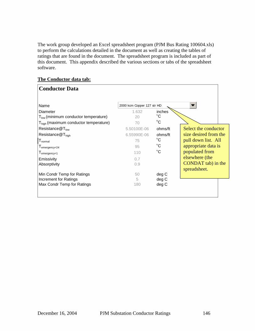
December 16, 2004 PJM Substation Conductor Ratings 146
The work group developed an Excel spreadsheet program (PJM Bus Rating 100604.xls) to perform the calculations detailed in the document as well as creating the tables of ratings that are found in the document. The spreadsheet program is included as part of this document. This appendix described the various sections or tabs of the spreadsheet software. The Conductor data tab:
Conductor Data
NameDiameter 1.632 inchesTlow (minimum conductor temperature) 20
oCThigh (maximum conductor temperature) 70
oCResistance@Tlow 5.50100E-06 ohms/ftResistance@Thigh 6.55990E-06 ohms/ftTnormal 75
oCTemergency<24 95
oCTemergency<1 110
oC
Emissivity 0.7Absorptivity 0.9
Min Condr Temp for Ratings 50 deg CIncrement for Ratings 5 deg CMax Condr Temp for Ratings 180 deg C
2000 kcm Copper 127 str HD
Select the conductor size desired from the pull down list. All appropriate data is populated from elsewhere (the CONDAT tab) in the spreadsheet.

December 16, 2004 PJM Substation Conductor Ratings 147
The Weather data tab: Weather Data
Drop Down Boxes and Red Entries are User Changeable
Suntime 3 14:00 Hours recomended by the PJM Bus Ampacity Taskforce
Degrees North Latitude 40 o 40 o recom by the PJM Bus Ampacity T. F.
Atmosphere 40 "Clear atmosphere recommended by the PJM Bus Ampacity TaskforceEmissivity ( 1 0.7 (selected when chosing conductor)Absorptivity ( 1 0.9 (selected when chosing conductor)
Ambient Temperature Range -15oC to 40oCElevation Above Sea Level 1000 ft 1000 ft recomended by the PJM Bus Ampacity TaskforceUser defined Wind speed for comparison V1 0 (ft/sec) User definable comparison wind speedWind speed for Published Ratings V2 2 (ft/sec)Azimuth of Conductor (N-S = 0, E-W = 90) 90 o 90 o recomended by the PJM Bus Ampacity Taskforce
Z1 (Angle between wind and conductor) 90 o 90 o recomended by the PJM Bus Ampacity Taskforce
Kangle (Wind direction factor) 1
Hc (Altitude of the sun) at 14:00 Hours 59.73 o
Qs (Total heat flux) at 14:00 Hours 96.09 (W/ft2)Zc (Azimuth of the sun) 245.20 o
1(Effective angle of incidence of the sun's rays) 117.23 o 2.00 Knots = 3.38 (ft/sec)5.00 miles/hr = 7.33 (ft/sec)
Total Heat Flux - Industrial Atmosphere 73.96 (W/ft2)Total Heat Flux - Clear Atmosphere 96.09 (W/ft2)
To convert from Knots or mph to fps, enter belowValue used
in calculations and derived
from the above data
Clear
14:00 Hours
The Publication Table Tab:
Bus Conductor: 2000 kcm Copper 127 str HD
2 fps
Rating -15 -10 -5 0 5 10 15 20 25 30 35 4050 2299 2187 2068 1940 1801 1649 1480 1286 1054 750 80 #NUM!60 2500 2401 2296 2185 2068 1941 1804 1655 1488 1297 1071 77670 2680 2590 2497 2399 2296 2186 2070 1945 1810 1662 1498 1310
Normal 75 2763 2678 2590 2497 2399 2297 2188 2072 1948 1814 1667 150380 2844 2762 2678 2590 2497 2400 2298 2190 2075 1952 1818 167290 2995 2920 2843 2763 2679 2592 2500 2404 2303 2196 2082 1960
Emergency (<24 hrs) 95 3067 2995 2921 2844 2764 2681 2594 2503 2407 2307 2200 2087100 3136 3067 2996 2922 2846 2766 2683 2597 2506 2411 2311 2205
Emergency (< 1 hr ) 110 3269 3205 3139 3071 3000 2927 2851 2772 2690 2604 2514 2420120 3395 3335 3274 3210 3145 3077 3007 2934 2859 2781 2699 2614130 3516 3460 3402 3342 3281 3218 3153 3086 3017 2944 2870 2792
WINTER SUMMER
Weather Assumptions: Emissivity = 0.7 Suntime = 14Absorptivity = 0.9 Degrees North Latitude= 40Atmosphere = Clear Elevation Above Sea Level= 1000Azimuth of Conductor (N-S = 0, E-W = 90) = 90 Z1 (Angle between wind and conductor) 90
Conductor : 2000 kcm Copper 127 str HD Outside Diameter = 1.632 inchesTlow = 20
oC Thigh = 70oC
Rlow = 5.5E-06 ohms/ft Rhigh = 6.6E-06 ohms/ft
Ambient Temperature (oC)Assumed Wind Speed =Rated
Operating Temperature
Select weather parameters from pull down boxes, and adjust the RED entries as appropriate. PJM recommendations are shown on the right.
This table has no changeable items. All values are calculated. This table was used to publish the tables in this document.

December 16, 2004 PJM Substation Conductor Ratings 148
The Comparison Table Tab:
Bus Conductor: 2000 kcm Copper 127 str HD
0 fps
Rating -15 -10 -5 0 5 10 15 20 25 30 35 40
50 1814 1694 1566 1428 1277 1108 910 659 214 #NUM! #NUM! #NUM!60 2032 1927 1816 1699 1574 1440 1293 1128 937 699 323 #NUM!70 2227 2132 2033 1930 1822 1707 1585 1454 1311 1151 966 739
Normal 75 2318 2227 2133 2035 1933 1826 1713 1592 1462 1320 1162 98180 2404 2317 2228 2135 2038 1937 1831 1719 1599 1471 1331 117590 2567 2487 2405 2320 2232 2141 2046 1947 1843 1733 1616 1490
Emergency (<24 hrs) 95 2644 2567 2488 2407 2323 2236 2145 2052 1953 1850 1741 1625100 2719 2645 2568 2490 2409 2326 2240 2151 2058 1960 1858 1750
Emergency (< 1 hr ) 110 2862 2792 2721 2648 2574 2497 2418 2336 2251 2164 2072 1976120 2997 2932 2865 2797 2728 2656 2583 2507 2429 2349 2266 2179130 3126 3065 3002 2938 2873 2806 2737 2667 2595 2521 2444 2365
WINTER SUMMER
2 fps
Rating -15 -10 -5 0 5 10 15 20 25 30 35 4050 2299 2187 2068 1940 1801 1649 1480 1286 1054 750 80 #NUM!60 2500 2401 2296 2185 2068 1941 1804 1655 1488 1297 1071 77670 2680 2590 2497 2399 2296 2186 2070 1945 1810 1662 1498 1310
Normal 75 2763 2678 2590 2497 2399 2297 2188 2072 1948 1814 1667 150380 2844 2762 2678 2590 2497 2400 2298 2190 2075 1952 1818 167290 2995 2920 2843 2763 2679 2592 2500 2404 2303 2196 2082 1960
Emergency (<24 hrs) 95 3067 2995 2921 2844 2764 2681 2594 2503 2407 2307 2200 2087100 3136 3067 2996 2922 2846 2766 2683 2597 2506 2411 2311 2205
Emergency (< 1 hr ) 110 3269 3205 3139 3071 3000 2927 2851 2772 2690 2604 2514 2420120 3395 3335 3274 3210 3145 3077 3007 2934 2859 2781 2699 2614130 3516 3460 3402 3342 3281 3218 3153 3086 3017 2944 2870 2792
WINTER SUMMER
Weather Assumptions: Emissivity = 0.7 Suntime = 14Absorptivity = 0.9 Degrees North Latitude= 40Atmosphere = Clear Elevation Above Sea Level= 1000Azimuth of Conductor (N-S = 0, E-W = 90) = 90 Z1 (Angle between wind and conductor) 90
Operating Temperature
Ambient Temperature (oC)
Assumed Wind Speed =
Assumed Wind Speed =
Ambient Temperature (oC)Rated
Operating Temperature
This table shows a comparison in rating based on a 2 fps wind speed recommended by PJM, and another wind speed that is chosen form the Weather Data tab. Here the alternative wind speed is 0 fps or no wind.
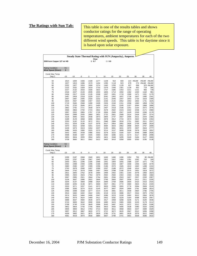
December 16, 2004 PJM Substation Conductor Ratings 149
The Ratings with Sun Tab:
Clear 2000 kcm Copper 127 str HD 1 0.7 1 0.9
Rating Condition: V1Wind Speed (ft/sec): 0
Condr Max Temp Deg C -15 -10 -5 0 5 10 15 20 25 30 35 40
50 1814 1694 1566 1428 1277 1108 910 659 214 #NUM! #NUM! #NUM!55 1927 1815 1696 1570 1434 1285 1118 923 679 274 #NUM! #NUM!60 2032 1927 1816 1699 1574 1440 1293 1128 937 699 323 #NUM!65 2132 2032 1928 1819 1703 1579 1446 1301 1139 952 719 36670 2227 2132 2033 1930 1822 1707 1585 1454 1311 1151 966 73975 2318 2227 2133 2035 1933 1826 1713 1592 1462 1320 1162 98180 2404 2317 2228 2135 2038 1937 1831 1719 1599 1471 1331 117585 2487 2404 2318 2229 2137 2042 1942 1837 1726 1607 1480 134190 2567 2487 2405 2320 2232 2141 2046 1947 1843 1733 1616 149095 2644 2567 2488 2407 2323 2236 2145 2052 1953 1850 1741 1625100 2719 2645 2568 2490 2409 2326 2240 2151 2058 1960 1858 1750105 2791 2720 2646 2571 2493 2413 2331 2245 2157 2064 1968 1866110 2862 2792 2721 2648 2574 2497 2418 2336 2251 2164 2072 1976115 2930 2863 2794 2724 2652 2578 2502 2423 2342 2258 2171 2080120 2997 2932 2865 2797 2728 2656 2583 2507 2429 2349 2266 2179125 3063 2999 2935 2869 2801 2732 2661 2589 2514 2436 2357 2274130 3126 3065 3002 2938 2873 2806 2737 2667 2595 2521 2444 2365135 3189 3129 3068 3006 2943 2878 2812 2744 2674 2602 2529 2453140 3250 3192 3133 3072 3011 2948 2884 2818 2751 2682 2611 2537145 3311 3254 3196 3137 3078 3017 2954 2891 2826 2759 2690 2619150 3370 3315 3258 3201 3143 3084 3023 2962 2898 2834 2767 2699155 3428 3374 3319 3264 3207 3150 3091 3031 2970 2907 2843 2777160 3486 3433 3380 3325 3270 3214 3157 3099 3039 2978 2916 2852165 3542 3491 3439 3386 3332 3278 3222 3165 3107 3048 2988 2926170 3598 3548 3497 3445 3393 3340 3286 3231 3174 3117 3058 2998175 3653 3604 3555 3504 3453 3401 3348 3295 3240 3184 3127 3069180 3708 3660 3611 3562 3512 3462 3410 3358 3305 3250 3195 3138
Rating Condition: V2Wind Speed (ft/sec): 2
Condr Max Temp Deg C -15 -10 -5 0 5 10 15 20 25 30 35 40
50 2299 2187 2068 1940 1801 1649 1480 1286 1054 750 80 #NUM!55 2403 2297 2186 2067 1940 1802 1652 1484 1291 1062 763 16960 2500 2401 2296 2185 2068 1941 1804 1655 1488 1297 1071 77665 2592 2498 2400 2296 2186 2069 1943 1807 1658 1493 1304 107970 2680 2590 2497 2399 2296 2186 2070 1945 1810 1662 1498 131075 2763 2678 2590 2497 2399 2297 2188 2072 1948 1814 1667 150380 2844 2762 2678 2590 2497 2400 2298 2190 2075 1952 1818 167285 2921 2843 2762 2678 2590 2499 2402 2301 2193 2078 1955 182390 2995 2920 2843 2763 2679 2592 2500 2404 2303 2196 2082 196095 3067 2995 2921 2844 2764 2681 2594 2503 2407 2307 2200 2087100 3136 3067 2996 2922 2846 2766 2683 2597 2506 2411 2311 2205105 3204 3137 3069 2998 2924 2848 2769 2686 2600 2510 2415 2315110 3269 3205 3139 3071 3000 2927 2851 2772 2690 2604 2514 2420115 3333 3271 3207 3141 3073 3003 2930 2855 2776 2694 2609 2519120 3395 3335 3274 3210 3145 3077 3007 2934 2859 2781 2699 2614125 3456 3398 3339 3277 3214 3149 3081 3011 2939 2864 2786 2705130 3516 3460 3402 3342 3281 3218 3153 3086 3017 2944 2870 2792135 3574 3520 3464 3406 3347 3286 3223 3159 3092 3022 2950 2876140 3632 3579 3524 3469 3411 3352 3292 3229 3164 3098 3029 2957145 3688 3637 3584 3530 3474 3417 3358 3298 3235 3171 3105 3036150 3743 3693 3642 3590 3536 3480 3424 3365 3305 3243 3178 3112155 3798 3749 3700 3649 3596 3543 3487 3431 3372 3312 3250 3186160 3852 3804 3756 3706 3656 3603 3550 3495 3438 3380 3320 3258165 3905 3859 3812 3763 3714 3663 3611 3558 3503 3447 3389 3329170 3957 3912 3867 3820 3772 3722 3672 3620 3567 3512 3456 3398175 4009 3965 3921 3875 3828 3780 3731 3681 3629 3576 3522 3465180 4061 4018 3974 3930 3884 3837 3790 3741 3691 3639 3586 3532
Steady State Thermal Rating with SUN (Ampacity), Amperes
This table is one of the results tables and shows conductor ratings for the range of operating temperatures, ambient temperatures for each of the two different wind speeds. This table is for daytime since it is based upon solar exposure.

December 16, 2004 PJM Substation Conductor Ratings 150
The Ratings without Sun Tab:
2000 kcm Copper 127 str HD 1 0.7 1 0.9
Rating Condition: V1Wind Speed (ft/sec): 0
Condr Max Temp Deg C -15 -10 -5 0 5 10 15 20 25 30 35 40
50 2235 2139 2039 1935 1826 1712 1591 1462 1323 1170 999 80055 2321 2229 2134 2035 1931 1824 1710 1590 1462 1323 1171 100060 2404 2315 2224 2129 2031 1929 1822 1709 1589 1462 1324 117265 2483 2398 2310 2220 2126 2028 1927 1820 1708 1589 1462 132570 2560 2478 2394 2306 2217 2123 2027 1926 1820 1708 1590 146375 2634 2555 2474 2390 2304 2214 2122 2026 1925 1820 1709 159180 2706 2630 2551 2470 2387 2301 2213 2121 2025 1926 1821 171085 2776 2702 2626 2548 2468 2385 2300 2212 2121 2026 1926 182290 2844 2772 2698 2623 2546 2466 2384 2300 2212 2122 2027 192895 2910 2840 2769 2696 2621 2544 2465 2384 2300 2213 2123 2029
100 2974 2906 2837 2767 2694 2620 2544 2466 2385 2301 2215 2125105 3037 2971 2904 2836 2765 2694 2620 2544 2467 2386 2303 2217110 3099 3035 2969 2903 2835 2765 2694 2621 2546 2468 2388 2306115 3159 3097 3033 2968 2902 2835 2766 2695 2623 2548 2471 2391120 3218 3157 3096 3033 2969 2903 2836 2767 2697 2625 2551 2474125 3276 3217 3157 3096 3033 2970 2904 2838 2770 2700 2628 2554130 3333 3275 3217 3157 3096 3035 2971 2907 2841 2773 2704 2632135 3389 3333 3276 3218 3159 3098 3037 2974 2910 2844 2777 2708140 3445 3390 3334 3277 3220 3161 3101 3040 2978 2914 2849 2782145 3499 3445 3391 3336 3280 3222 3164 3105 3044 2982 2919 2854150 3553 3500 3447 3393 3339 3283 3226 3168 3109 3049 2988 2925155 3606 3555 3503 3450 3397 3342 3287 3231 3173 3115 3055 2994160 3658 3608 3558 3506 3454 3401 3347 3292 3236 3179 3121 3061165 3710 3661 3612 3561 3510 3459 3406 3352 3298 3242 3186 3128170 3762 3714 3665 3616 3566 3516 3464 3412 3359 3305 3249 3193175 3813 3766 3718 3670 3621 3572 3522 3471 3419 3366 3312 3257180 3863 3817 3771 3724 3676 3628 3579 3529 3478 3427 3374 3320
Rating Condition: V2Wind Speed (ft/sec): 2
Condr Max Temp Deg C -15 -10 -5 0 5 10 15 20 25 30 35 40
50 2644 2547 2445 2338 2224 2103 1973 1832 1678 1505 1308 107155 2729 2637 2540 2439 2332 2219 2098 1969 1828 1674 1502 130560 2810 2722 2631 2534 2434 2327 2214 2094 1965 1825 1671 150065 2888 2804 2716 2625 2529 2429 2323 2210 2091 1962 1822 166970 2962 2882 2798 2711 2620 2525 2425 2319 2207 2088 1959 182075 3034 2957 2877 2793 2707 2616 2521 2421 2316 2204 2085 195780 3103 3029 2952 2872 2789 2703 2613 2518 2419 2314 2202 208385 3170 3099 3025 2948 2869 2786 2700 2610 2516 2417 2312 220190 3235 3166 3095 3022 2945 2866 2784 2698 2608 2514 2415 231195 3299 3232 3163 3092 3019 2943 2864 2782 2697 2607 2513 2414
100 3360 3296 3229 3161 3090 3017 2942 2863 2781 2696 2606 2513105 3420 3358 3294 3228 3160 3089 3016 2941 2862 2781 2695 2606110 3479 3418 3356 3292 3227 3159 3089 3016 2941 2862 2781 2696115 3536 3477 3417 3356 3292 3227 3159 3089 3016 2941 2863 2782120 3592 3535 3477 3417 3356 3292 3227 3160 3090 3018 2943 2865125 3647 3592 3535 3478 3418 3357 3294 3228 3161 3091 3019 2944130 3701 3648 3593 3537 3479 3419 3358 3295 3230 3163 3094 3022135 3754 3702 3649 3594 3538 3481 3422 3361 3298 3233 3166 3097140 3807 3756 3704 3651 3597 3541 3484 3425 3364 3301 3236 3169145 3858 3809 3759 3707 3654 3600 3544 3487 3428 3367 3305 3240150 3909 3861 3812 3762 3711 3658 3604 3548 3491 3432 3372 3309155 3959 3913 3865 3816 3766 3715 3662 3608 3553 3496 3437 3377160 4009 3964 3917 3869 3821 3771 3720 3667 3614 3558 3501 3443165 4058 4014 3968 3922 3875 3826 3777 3726 3673 3620 3564 3507170 4107 4064 4019 3974 3928 3881 3832 3783 3732 3680 3626 3571175 4155 4113 4070 4026 3981 3935 3887 3839 3790 3739 3687 3633180 4203 4162 4120 4077 4033 3988 3942 3895 3847 3797 3747 3694
Steady State Thermal Rating without SUN (Ampacity), Amperes
This table is another of the results tables and shows conductor ratings for the range of operating temperatures, ambient temperatures for each of the two different wind speeds. This table is for night time since it is absent solar exposure.

December 16, 2004 PJM Substation Conductor Ratings 151
The CONDAT Tab: Conductor Data Table Note: FOR COPPER TUBES:
R70c = 1.1925*R20cEmissivity Absorptivity
Name Outside Diam. Rlow Tlow Rhigh Thigh Tnormal Temergency<24 Temergency<1
inches u ohm/ft deg C u ohm/ft deg C deg C deg C deg C
1" Alum, Sched 40, 6061 Alloy 1.315 41.210 20 46.680 70 90 115 130 0.5 0.51-1/2" Alum, Sched 40, 6061 Alloy 1.900 25.450 20 28.820 70 90 115 130 0.5 0.52" Alum, Sched 40, 6061 Alloy 2.375 18.940 20 21.450 70 90 115 130 0.5 0.52-1/2" Alum, Sched 40, 6061 Alloy 2.875 11.950 20 13.530 70 90 115 130 0.5 0.53" Alum, Sched 40, 6061 Alloy 3.500 9.138 20 10.350 70 90 115 130 0.5 0.53-1/2" Alum, Sched 40, 6061 Alloy 4.000 7.957 20 8.613 70 90 115 130 0.5 0.54" Alum, Sched 40, 6061 Alloy 4.500 6.415 20 7.280 70 90 115 130 0.5 0.55" Alum, Sched 40, 6061 Alloy 5.563 4.735 20 5.373 70 90 115 130 0.5 0.56" Alum, Sched 40, 6061 Alloy 6.625 3.648 20 4.140 70 90 115 130 0.5 0.51" Alum, Sched 80, 6061 Alloy 1.315 31.860 20 36.080 70 90 115 130 0.5 0.51-1/2" Alum, Sched 80, 6061 Alloy 1.900 19.060 20 21.590 70 90 115 130 0.5 0.52" Alum, Sched 80, 6061 Alloy 2.375 13.780 20 15.610 70 90 115 130 0.5 0.52-1/2" Alum, Sched 80, 6061 Alloy 2.875 9.033 20 10.270 70 90 115 130 0.5 0.53" Alum, Sched 80, 6061 Alloy 3.500 6.751 20 7.683 70 90 115 130 0.5 0.53-1/2" Alum, Sched 80, 6061 Alloy 4.000 5.536 20 6.313 70 90 115 130 0.5 0.54" Alum, Sched 80, 6061 Alloy 4.500 4.620 20 5.284 70 90 115 130 0.5 0.55" Alum, Sched 80, 6061 Alloy 5.563 3.361 20 3.833 70 90 115 130 0.5 0.56" Alum, Sched 80, 6061 Alloy 6.625 2.425 20 2.790 70 90 115 130 0.5 0.51" Alum, Sched 40, 6063 Alloy 1.315 31.120 20 36.570 70 90 115 130 0.5 0.51-1/2" Alum, Sched 40, 6063 Alloy 1.900 19.220 20 22.590 70 90 115 130 0.5 0.52" Alum, Sched 40, 6063 Alloy 2.375 14.300 20 16.820 70 90 115 130 0.5 0.52-1/2" Alum, Sched 40, 6063 Alloy 2.875 9.020 20 10.610 70 90 115 130 0.5 0.53" Alum, Sched 40, 6063 Alloy 3.500 6.896 20 8.122 70 90 115 130 0.5 0.53-1/2" Alum, Sched 40, 6063 Alloy 4.000 5.735 20 6.759 70 90 115 130 0.5 0.54" Alum, Sched 40, 6063 Alloy 4.500 4.842 20 5.713 70 90 115 130 0.5 0.54-1/2" Alum, Sched 40, 6063 Alloy 5.000 4.167 20 4.920 70 90 115 130 0.5 0.55" Alum, Sched 40, 6063 Alloy 5.563 3.574 20 4.221 70 90 115 130 0.5 0.56" Alum, Sched 40, 6063 Alloy 6.625 2.754 20 3.257 70 90 115 130 0.5 0.51" Alum, Sched 80, 6063 Alloy 1.315 24.06 20 28.270 70 90 115 130 0.5 0.51-1/2" Alum, Sched 80, 6063 Alloy 1.900 14.39 20 16.910 70 90 115 130 0.5 0.52" Alum, Sched 80, 6063 Alloy 2.375 10.41 20 12.300 70 90 115 130 0.5 0.52-1/2" Alum, Sched 80, 6063 Alloy 2.875 6.819 20 8.068 70 90 115 130 0.5 0.53" Alum, Sched 80, 6063 Alloy 3.500 5.096 20 6.048 70 90 115 130 0.5 0.53-1/2" Alum, Sched 80, 6063 Alloy 4.000 4.179 20 4.974 70 90 115 130 0.5 0.54" Alum, Sched 80, 6063 Alloy 4.500 3.488 20 4.172 80 90 115 130 0.5 0.54-1/2" Alum, Sched 80, 6063 Alloy 5.000 2.967 20 3.559 70 90 115 130 0.5 0.55" Alum, Sched 80, 6063 Alloy 5.563 2.515 20 3.032 70 90 115 130 0.5 0.56" Alum, Sched 80, 6063 Alloy 6.625 1.829 20 2.248 70 90 115 130 0.5 0.53/4" Copper, Schedule 40, 98% ICAS 1.050 24.79 20 29.562 70 90 115 130 0.85 0.851" Copper, Schedule 40, 98% ICAS 1.315 17.600 20 20.988 70 90 115 130 0.85 0.851-1/4" Copper, Schedule 40, 98% ICAS 1.660 11.970 20 14.274 70 90 115 130 0.85 0.851-1/2" Copper, Schedule 40, 98% ICAS 1.900 10.080 20 12.020 70 90 115 130 0.85 0.852" Copper, Schedule 40, 98% ICAS 2.375 7.620 20 9.087 70 90 115 130 0.85 0.852-1/2" Copper, Schedule 40, 98% ICAS 2.875 5.250 20 6.261 70 90 115 130 0.85 0.853" Copper, Schedule 40, 98% ICAS 3.500 3.682 20 4.391 70 90 115 130 0.85 0.853-1/2" Copper, Schedule 40, 98% ICAS 4.000 2.822 20 3.365 70 90 115 130 0.85 0.854" Copper, Schedule 40, 98% ICAS 4.500 2.490 20 2.969 70 90 115 130 0.85 0.851" Copper, Schedule 80, 98% ICAS 1.315 12.830 20 15.300 70 90 115 130 0.85 0.851-1/2" Copper, Schedule 80, 98% ICAS 1.900 7.680 20 9.158 70 90 115 130 0.85 0.852" Copper, Schedule 80, 98% ICAS 2.375 5.558 20 6.628 70 90 115 130 0.85 0.852-1/2"Copper, Schedule 80, 98% ICAS 2.875 3.641 20 4.342 70 90 115 130 0.85 0.853" Copper, Schedule 80, 98% ICAS 3.500 2.723 20 3.247 70 90 115 130 0.85 0.853-1/2" Copper, Schedule 80, 98% ICAS 4.000 2.240 20 2.671 70 90 115 130 0.85 0.854" Copper, Schedule 80, 98% ICAS 4.500 1.866 20 2.225 70 90 115 130 0.85 0.851/0 ACSR 6/1 0.398 169.508 25 216.856 75 105 130 140 0.7 0.92/0 ACSR 6/1 0.447 128.977 25 176.515 75 105 130 140 0.7 0.93/0 ACSR 6/1 0.502 102.462 25 144.318 75 105 130 140 0.7 0.94/0 ACSR 6/1 0.563 81.250 25 118.939 75 105 130 140 0.7 0.9159 kcm ACSR 12/7 0.756 103.409 25 181.439 75 105 130 140 0.7 0.9203.2 kcm ACSR 16/19 0.714 77.841 25 155.303 75 105 130 140 0.7 0.9266.8 kcm ACSR 26/7 0.642 65.095 25 77.898 75 105 130 140 0.7 0.9266.8 kcm ACSR 30/7 0.660 64.640 25 77.330 75 105 130 140 0.7 0.9336.4 kcm ACSR 18/1 0.684 52.197 25 62.462 75 105 130 140 0.7 0.9336.4 kcm ACSR 26/7 0.720 51.667 25 61.818 75 105 130 140 0.7 0.9336.4 kcm ACSR 30/7 0.741 51.288 25 61.364 75 105 130 140 0.7 0.9
Rated Operating Temperatures
This table is the source data for all of the wire and bus sizes available in the spreadsheet. 40 rows are available at the bottom for user additions.

December 16, 2004 PJM Substation Conductor Ratings 152
The DeltaT Tab:
2000 kcm Copper 127 str HD
Rating Condition
Wind Speed (ft/sec)
Condr Max
Temp Deg C -15 -10 -5 0 5 10 15 20 25 30 35 40
V1 0 50 65.0 60.0 55.0 50.0 45.0 40.0 35.0 30.0 25.0 20.0 15.0 10.0V2 2 50 65.0 60.0 55.0 50.0 45.0 40.0 35.0 30.0 25.0 20.0 15.0 10.0
V1 0 55 70.0 65.0 60.0 55.0 50.0 45.0 40.0 35.0 30.0 25.0 20.0 15.0V2 2 55 70.0 65.0 60.0 55.0 50.0 45.0 40.0 35.0 30.0 25.0 20.0 15.0
V1 0 60 75.0 70.0 65.0 60.0 55.0 50.0 45.0 40.0 35.0 30.0 25.0 20.0V2 2 60 75.0 70.0 65.0 60.0 55.0 50.0 45.0 40.0 35.0 30.0 25.0 20.0
V1 0 65 80.0 75.0 70.0 65.0 60.0 55.0 50.0 45.0 40.0 35.0 30.0 25.0V2 2 65 80.0 75.0 70.0 65.0 60.0 55.0 50.0 45.0 40.0 35.0 30.0 25.0
V1 0 70 85.0 80.0 75.0 70.0 65.0 60.0 55.0 50.0 45.0 40.0 35.0 30.0V2 2 70 85.0 80.0 75.0 70.0 65.0 60.0 55.0 50.0 45.0 40.0 35.0 30.0
V1 0 75 90.0 85.0 80.0 75.0 70.0 65.0 60.0 55.0 50.0 45.0 40.0 35.0V2 2 75 90.0 85.0 80.0 75.0 70.0 65.0 60.0 55.0 50.0 45.0 40.0 35.0
V1 0 80 95.0 90.0 85.0 80.0 75.0 70.0 65.0 60.0 55.0 50.0 45.0 40.0V2 2 80 95.0 90.0 85.0 80.0 75.0 70.0 65.0 60.0 55.0 50.0 45.0 40.0
V1 0 85 100.0 95.0 90.0 85.0 80.0 75.0 70.0 65.0 60.0 55.0 50.0 45.0V2 2 85 100.0 95.0 90.0 85.0 80.0 75.0 70.0 65.0 60.0 55.0 50.0 45.0
V1 0 90 105.0 100.0 95.0 90.0 85.0 80.0 75.0 70.0 65.0 60.0 55.0 50.0V2 2 90 105.0 100.0 95.0 90.0 85.0 80.0 75.0 70.0 65.0 60.0 55.0 50.0
V1 0 95 110.0 105.0 100.0 95.0 90.0 85.0 80.0 75.0 70.0 65.0 60.0 55.0V2 2 95 110.0 105.0 100.0 95.0 90.0 85.0 80.0 75.0 70.0 65.0 60.0 55.0
V1 0 100 115.0 110.0 105.0 100.0 95.0 90.0 85.0 80.0 75.0 70.0 65.0 60.0V2 2 100 115.0 110.0 105.0 100.0 95.0 90.0 85.0 80.0 75.0 70.0 65.0 60.0
V1 0 105 120.0 115.0 110.0 105.0 100.0 95.0 90.0 85.0 80.0 75.0 70.0 65.0V2 2 105 120.0 115.0 110.0 105.0 100.0 95.0 90.0 85.0 80.0 75.0 70.0 65.0
V1 0 110 125.0 120.0 115.0 110.0 105.0 100.0 95.0 90.0 85.0 80.0 75.0 70.0V2 2 110 125.0 120.0 115.0 110.0 105.0 100.0 95.0 90.0 85.0 80.0 75.0 70.0
V1 0 115 130.0 125.0 120.0 115.0 110.0 105.0 100.0 95.0 90.0 85.0 80.0 75.0V2 2 115 130.0 125.0 120.0 115.0 110.0 105.0 100.0 95.0 90.0 85.0 80.0 75.0
V1 0 120 135.0 130.0 125.0 120.0 115.0 110.0 105.0 100.0 95.0 90.0 85.0 80.0V2 2 120 135.0 130.0 125.0 120.0 115.0 110.0 105.0 100.0 95.0 90.0 85.0 80.0
V1 0 125 140.0 135.0 130.0 125.0 120.0 115.0 110.0 105.0 100.0 95.0 90.0 85.0V2 2 125 140.0 135.0 130.0 125.0 120.0 115.0 110.0 105.0 100.0 95.0 90.0 85.0
V1 0 130 145.0 140.0 135.0 130.0 125.0 120.0 115.0 110.0 105.0 100.0 95.0 90.0V2 2 130 145.0 140.0 135.0 130.0 125.0 120.0 115.0 110.0 105.0 100.0 95.0 90.0
V1 0 135 150.0 145.0 140.0 135.0 130.0 125.0 120.0 115.0 110.0 105.0 100.0 95.0V2 2 135 150.0 145.0 140.0 135.0 130.0 125.0 120.0 115.0 110.0 105.0 100.0 95.0
V1 0 140 155.0 150.0 145.0 140.0 135.0 130.0 125.0 120.0 115.0 110.0 105.0 100.0V2 2 140 155.0 150.0 145.0 140.0 135.0 130.0 125.0 120.0 115.0 110.0 105.0 100.0
V1 0 145 160.0 155.0 150.0 145.0 140.0 135.0 130.0 125.0 120.0 115.0 110.0 105.0V2 2 145 160.0 155.0 150.0 145.0 140.0 135.0 130.0 125.0 120.0 115.0 110.0 105.0
V1 0 150 165.0 160.0 155.0 150.0 145.0 140.0 135.0 130.0 125.0 120.0 115.0 110.0V2 2 150 165.0 160.0 155.0 150.0 145.0 140.0 135.0 130.0 125.0 120.0 115.0 110.0
V1 0 155 170.0 165.0 160.0 155.0 150.0 145.0 140.0 135.0 130.0 125.0 120.0 115.0V2 2 155 170.0 165.0 160.0 155.0 150.0 145.0 140.0 135.0 130.0 125.0 120.0 115.0
DELTA t (degrees C) = (T c - T a)
This tab is used for intermediate steps in the calculation. No user inputs are required. The table shows the difference in temperature between the conductor temperature and ambient temperature.

December 16, 2004 PJM Substation Conductor Ratings 153
The TFilm tab:
2000 kcm Copper 127 str HD
Rating Con
Wind Speed (ft/sec)
Condr Max Temp
Deg C -15 -10 -5 0 5 10 15 20 25 30 35 40
V1 0 50 17.5 20.0 22.5 25.0 27.5 30.0 32.5 35.0 37.5 40.0 42.5 45.0V2 2 50 17.5 20.0 22.5 25.0 27.5 30.0 32.5 35.0 37.5 40.0 42.5 45.0
V1 0 55 20.0 22.5 25.0 27.5 30.0 32.5 35.0 37.5 40.0 42.5 45.0 47.5V2 2 55 20.0 22.5 25.0 27.5 30.0 32.5 35.0 37.5 40.0 42.5 45.0 47.5
V1 0 60 22.5 25.0 27.5 30.0 32.5 35.0 37.5 40.0 42.5 45.0 47.5 50.0V2 2 60 22.5 25.0 27.5 30.0 32.5 35.0 37.5 40.0 42.5 45.0 47.5 50.0
V1 0 65 25.0 27.5 30.0 32.5 35.0 37.5 40.0 42.5 45.0 47.5 50.0 52.5V2 2 65 25.0 27.5 30.0 32.5 35.0 37.5 40.0 42.5 45.0 47.5 50.0 52.5
V1 0 70 27.5 30.0 32.5 35.0 37.5 40.0 42.5 45.0 47.5 50.0 52.5 55.0V2 2 70 27.5 30.0 32.5 35.0 37.5 40.0 42.5 45.0 47.5 50.0 52.5 55.0
V1 0 75 30.0 32.5 35.0 37.5 40.0 42.5 45.0 47.5 50.0 52.5 55.0 57.5V2 2 75 30.0 32.5 35.0 37.5 40.0 42.5 45.0 47.5 50.0 52.5 55.0 57.5
V1 0 80 32.5 35.0 37.5 40.0 42.5 45.0 47.5 50.0 52.5 55.0 57.5 60.0V2 2 80 32.5 35.0 37.5 40.0 42.5 45.0 47.5 50.0 52.5 55.0 57.5 60.0
T film (degrees C) = (T c + T a)/2
The Air Density tab:
2000 kcm Copper 127 str HD
Rating Con
Wind Speed (ft/sec)
Condr Max Temp
Deg C -15 -10 -5 0 5 10 15 20 25 30 35 40
V1 0 50 0.073134 0.072509 0.071894 0.07129 0.070696 0.070112 0.069537 0.068972 0.068415 0.067868 0.067329 0.066799V2 2 50 0.073134 0.072509 0.071894 0.07129 0.070696 0.070112 0.069537 0.068972 0.068415 0.067868 0.067329 0.066799
V1 0 55 0.072509 0.071894 0.07129 0.070696 0.070112 0.069537 0.068972 0.068415 0.067868 0.067329 0.066799 0.066277V2 2 55 0.072509 0.071894 0.07129 0.070696 0.070112 0.069537 0.068972 0.068415 0.067868 0.067329 0.066799 0.066277
V1 0 60 0.071894 0.07129 0.070696 0.070112 0.069537 0.068972 0.068415 0.067868 0.067329 0.066799 0.066277 0.065763V2 2 60 0.071894 0.07129 0.070696 0.070112 0.069537 0.068972 0.068415 0.067868 0.067329 0.066799 0.066277 0.065763
V1 0 65 0.07129 0.070696 0.070112 0.069537 0.068972 0.068415 0.067868 0.067329 0.066799 0.066277 0.065763 0.065258V2 2 65 0.07129 0.070696 0.070112 0.069537 0.068972 0.068415 0.067868 0.067329 0.066799 0.066277 0.065763 0.065258
V1 0 70 0.070696 0.070112 0.069537 0.068972 0.068415 0.067868 0.067329 0.066799 0.066277 0.065763 0.065258 0.064759V2 2 70 0.070696 0.070112 0.069537 0.068972 0.068415 0.067868 0.067329 0.066799 0.066277 0.065763 0.065258 0.064759
V1 0 75 0.070112 0.069537 0.068972 0.068415 0.067868 0.067329 0.066799 0.066277 0.065763 0.065258 0.064759 0.064269V2 2 75 0.070112 0.069537 0.068972 0.068415 0.067868 0.067329 0.066799 0.066277 0.065763 0.065258 0.064759 0.064269
V1 0 80 0.069537 0.068972 0.068415 0.067868 0.067329 0.066799 0.066277 0.065763 0.065258 0.064759 0.064269 0.063785V2 2 80 0.069537 0.068972 0.068415 0.067868 0.067329 0.066799 0.066277 0.065763 0.065258 0.064759 0.064269 0.063785
Air Density ( f), (lb/ft3)
This tab is used for intermediate steps in the calculation. No user inputs are required. The table shows the temperature of the air film between the conductor and ambient environment.
This tab is used for intermediate steps in the calculation. No user inputs are required. The table shows the air density around the conductor based on temperature.

December 16, 2004 PJM Substation Conductor Ratings 154
The Air Viscosity tab:
2000 kcm Copper 127 str HD
Rating Con
Wind Speed (ft/sec)
Condr Max Temp
Deg C -15 -10 -5 0 5 10 15 20 25 30 35 40
V1 0 50 0.043572 0.043863 0.044152 0.04444 0.044727 0.045012 0.045297 0.04558 0.045862 0.046143 0.046423 0.046701V2 2 50 0.043572 0.043863 0.044152 0.04444 0.044727 0.045012 0.045297 0.04558 0.045862 0.046143 0.046423 0.046701
V1 0 55 0.043863 0.044152 0.04444 0.044727 0.045012 0.045297 0.04558 0.045862 0.046143 0.046423 0.046701 0.046979V2 2 55 0.043863 0.044152 0.04444 0.044727 0.045012 0.045297 0.04558 0.045862 0.046143 0.046423 0.046701 0.046979
V1 0 60 0.044152 0.04444 0.044727 0.045012 0.045297 0.04558 0.045862 0.046143 0.046423 0.046701 0.046979 0.047255V2 2 60 0.044152 0.04444 0.044727 0.045012 0.045297 0.04558 0.045862 0.046143 0.046423 0.046701 0.046979 0.047255
V1 0 65 0.04444 0.044727 0.045012 0.045297 0.04558 0.045862 0.046143 0.046423 0.046701 0.046979 0.047255 0.047531V2 2 65 0.04444 0.044727 0.045012 0.045297 0.04558 0.045862 0.046143 0.046423 0.046701 0.046979 0.047255 0.047531
V1 0 70 0.044727 0.045012 0.045297 0.04558 0.045862 0.046143 0.046423 0.046701 0.046979 0.047255 0.047531 0.047805V2 2 70 0.044727 0.045012 0.045297 0.04558 0.045862 0.046143 0.046423 0.046701 0.046979 0.047255 0.047531 0.047805
V1 0 75 0.045012 0.045297 0.04558 0.045862 0.046143 0.046423 0.046701 0.046979 0.047255 0.047531 0.047805 0.048078V2 2 75 0.045012 0.045297 0.04558 0.045862 0.046143 0.046423 0.046701 0.046979 0.047255 0.047531 0.047805 0.048078
V1 0 80 0.045297 0.04558 0.045862 0.046143 0.046423 0.046701 0.046979 0.047255 0.047531 0.047805 0.048078 0.04835V2 2 80 0.045297 0.04558 0.045862 0.046143 0.046423 0.046701 0.046979 0.047255 0.047531 0.047805 0.048078 0.04835
Absolute Viscosity of Air ( f), (lb/ft*h)
The qc tab:
2000 kcm Copper 127 str HD
Rating Condition
Wind Speed (ft/sec)
Condr Max
Temp Deg C -15 -10 -5 0 5 10 15 20 25 30 35 40
V1 0 50 20.40 18.37 16.41 14.51 12.66 10.88 9.17 7.53 5.97 4.50 3.13 1.88V2 2 50 32.65 30.12 27.60 25.08 22.56 20.04 17.53 15.02 12.51 10.01 7.50 5.00
V1 0 55 22.28 20.22 18.22 16.27 14.39 12.56 10.80 9.10 7.47 5.93 4.47 3.11V2 2 55 35.14 32.61 30.09 27.57 25.05 22.54 20.03 17.52 15.01 12.50 10.00 7.50
V1 0 60 24.18 22.09 20.05 18.07 16.14 14.27 12.46 10.71 9.03 7.42 5.88 4.43V2 2 60 37.63 35.11 32.58 30.06 27.55 25.03 22.52 20.01 17.50 15.00 12.49 9.99
V1 0 65 26.10 23.98 21.91 19.89 17.92 16.01 14.15 12.36 10.62 8.96 7.36 5.84V2 2 65 40.12 37.60 35.08 32.56 30.04 27.53 25.01 22.50 20.00 17.49 14.99 12.49
V1 0 70 28.04 25.89 23.78 21.73 19.73 17.78 15.88 14.04 12.26 10.54 8.89 7.30V2 2 70 42.61 40.09 37.56 35.05 32.53 30.02 27.51 25.00 22.49 19.98 17.48 14.98
V1 0 75 29.99 27.81 25.68 23.59 21.55 19.57 17.64 15.76 13.93 12.17 10.46 8.82V2 2 75 45.10 42.57 40.05 37.53 35.02 32.51 30.00 27.49 24.98 22.48 19.97 17.47
V1 0 80 31.96 29.75 27.59 25.47 23.40 21.38 19.42 17.50 15.63 13.83 12.07 10.38V2 2 80 47.58 45.06 42.54 40.02 37.51 35.00 32.49 29.98 27.47 24.97 22.46 19.96
Convected Heat Loss (q c), Watts Per Foot of Conductor ( max of qc0, kqc1, or kqc2)
This tab is used for intermediate steps in the calculation. No user inputs are required. The table shows the viscosity of the air around the conductor.
This tab is used for intermediate steps in the calculation. No user inputs are required. The table shows the convection heat loss from a 1 foot length of conductor.

December 16, 2004 PJM Substation Conductor Ratings 155
The µr tab:
2000 kcm Copper 127 str HD
Rating Con
Wind Speed (ft/sec)
Condr Max Temp
Deg C -15 -10 -5 0 5 10 15 20 25 30 35 40
V1 0 50 0.007786 0.007843 0.0079 0.007957 0.008014 0.00807 0.008127 0.008184 0.008241 0.008297 0.008354 0.008411V2 2 50 0.007786 0.007843 0.0079 0.007957 0.008014 0.00807 0.008127 0.008184 0.008241 0.008297 0.008354 0.008411
V1 0 55 0.007843 0.0079 0.007957 0.008014 0.00807 0.008127 0.008184 0.008241 0.008297 0.008354 0.008411 0.008467V2 2 55 0.007843 0.0079 0.007957 0.008014 0.00807 0.008127 0.008184 0.008241 0.008297 0.008354 0.008411 0.008467
V1 0 60 0.0079 0.007957 0.008014 0.00807 0.008127 0.008184 0.008241 0.008297 0.008354 0.008411 0.008467 0.008524V2 2 60 0.0079 0.007957 0.008014 0.00807 0.008127 0.008184 0.008241 0.008297 0.008354 0.008411 0.008467 0.008524
V1 0 65 0.007957 0.008014 0.00807 0.008127 0.008184 0.008241 0.008297 0.008354 0.008411 0.008467 0.008524 0.008581V2 2 65 0.007957 0.008014 0.00807 0.008127 0.008184 0.008241 0.008297 0.008354 0.008411 0.008467 0.008524 0.008581
V1 0 70 0.008014 0.00807 0.008127 0.008184 0.008241 0.008297 0.008354 0.008411 0.008467 0.008524 0.008581 0.008637V2 2 70 0.008014 0.00807 0.008127 0.008184 0.008241 0.008297 0.008354 0.008411 0.008467 0.008524 0.008581 0.008637
V1 0 75 0.00807 0.008127 0.008184 0.008241 0.008297 0.008354 0.008411 0.008467 0.008524 0.008581 0.008637 0.008694V2 2 75 0.00807 0.008127 0.008184 0.008241 0.008297 0.008354 0.008411 0.008467 0.008524 0.008581 0.008637 0.008694
V1 0 80 0.008127 0.008184 0.008241 0.008297 0.008354 0.008411 0.008467 0.008524 0.008581 0.008637 0.008694 0.00875V2 2 80 0.008127 0.008184 0.008241 0.008297 0.008354 0.008411 0.008467 0.008524 0.008581 0.008637 0.008694 0.00875
Thermal Conductivity of Air (k f) at Temperature , T film W/ft (degrees C)
The qs tab:
Clear 2000 kcm Copper 127 str HD [ 0.7 [ 0.9
Rating Condition
Wind Speed (ft/sec)
Condr Max
Temp Deg C -15 -10 -5 0 5 10 15 20 25 30 35 40
V1 0 50 10.458 10.458 10.458 10.458 10.458 10.458 10.458 10.458 10.458 10.458 10.458 10.458V2 2 50 10.458 10.458 10.458 10.458 10.458 10.458 10.458 10.458 10.458 10.458 10.458 10.458
V1 0 55 10.458 10.458 10.458 10.458 10.458 10.458 10.458 10.458 10.458 10.458 10.458 10.458V2 2 55 10.458 10.458 10.458 10.458 10.458 10.458 10.458 10.458 10.458 10.458 10.458 10.458
V1 0 60 10.458 10.458 10.458 10.458 10.458 10.458 10.458 10.458 10.458 10.458 10.458 10.458V2 2 60 10.458 10.458 10.458 10.458 10.458 10.458 10.458 10.458 10.458 10.458 10.458 10.458
V1 0 65 10.458 10.458 10.458 10.458 10.458 10.458 10.458 10.458 10.458 10.458 10.458 10.458V2 2 65 10.458 10.458 10.458 10.458 10.458 10.458 10.458 10.458 10.458 10.458 10.458 10.458
V1 0 70 10.458 10.458 10.458 10.458 10.458 10.458 10.458 10.458 10.458 10.458 10.458 10.458V2 2 70 10.458 10.458 10.458 10.458 10.458 10.458 10.458 10.458 10.458 10.458 10.458 10.458
V1 0 75 10.458 10.458 10.458 10.458 10.458 10.458 10.458 10.458 10.458 10.458 10.458 10.458V2 2 75 10.458 10.458 10.458 10.458 10.458 10.458 10.458 10.458 10.458 10.458 10.458 10.458
V1 0 80 10.458 10.458 10.458 10.458 10.458 10.458 10.458 10.458 10.458 10.458 10.458 10.458V2 2 80 10.458 10.458 10.458 10.458 10.458 10.458 10.458 10.458 10.458 10.458 10.458 10.458
Solar Heat Gain (q s), Watts Per Foot of Conductor
This tab is used for intermediate steps in the calculation. No user inputs are required. The table shows the thermal conductivity of the air around the conductor.
This tab is used for intermediate steps in the calculation. No user inputs are required. The table shows the heat gain to the conductor due to solar heat input. This is only used for day time ratings.

December 16, 2004 PJM Substation Conductor Ratings 156
The qr tab:
2000 kcm Copper 127 str HD [ 0.7 [ 0.9
Rating Condition
Wind Speed (ft/sec)
Condr Max
Temp Deg C -15 -10 -5 0 5 10 15 20 25 30 35 40
V1 0 50 10.2563 9.6944 9.0995 8.4703 7.8057 7.1041 6.3644 5.5852 4.7650 3.9025 2.9962 2.0447V2 2 50 10.2563 9.6944 9.0995 8.4703 7.8057 7.1041 6.3644 5.5852 4.7650 3.9025 2.9962 2.0447
V1 0 55 11.3525 10.7905 10.1957 9.5665 8.9018 8.2003 7.4606 6.6814 5.8612 4.9987 4.0924 3.1409V2 2 55 11.3525 10.7905 10.1957 9.5665 8.9018 8.2003 7.4606 6.6814 5.8612 4.9987 4.0924 3.1409
V1 0 60 12.4999 11.9380 11.3431 10.7140 10.0493 9.3478 8.6081 7.8289 7.0087 6.1462 5.2399 4.2883V2 2 60 12.4999 11.9380 11.3431 10.7140 10.0493 9.3478 8.6081 7.8289 7.0087 6.1462 5.2399 4.2883
V1 0 65 13.7003 13.1384 12.5435 11.9143 11.2497 10.5482 9.8085 9.0292 8.2090 7.3465 6.4402 5.4887V2 2 65 13.7003 13.1384 12.5435 11.9143 11.2497 10.5482 9.8085 9.0292 8.2090 7.3465 6.4402 5.4887
V1 0 70 14.9551 14.3932 13.7983 13.1692 12.5045 11.8030 11.0633 10.2840 9.4638 8.6013 7.6950 6.7435V2 2 70 14.9551 14.3932 13.7983 13.1692 12.5045 11.8030 11.0633 10.2840 9.4638 8.6013 7.6950 6.7435
V1 0 75 16.2660 15.7041 15.1092 14.4801 13.8154 13.1139 12.3742 11.5949 10.7747 9.9122 9.0059 8.0544V2 2 75 16.2660 15.7041 15.1092 14.4801 13.8154 13.1139 12.3742 11.5949 10.7747 9.9122 9.0059 8.0544
V1 0 80 17.6347 17.0727 16.4779 15.8487 15.1840 14.4825 13.7428 12.9636 12.1434 11.2809 10.3746 9.4231V2 2 80 17.6347 17.0727 16.4779 15.8487 15.1840 14.4825 13.7428 12.9636 12.1434 11.2809 10.3746 9.4231
Radiated Heat Loss (q r), Watts Per Foot of Conductor
The Resistance tab:
2000 kcm Copper 127 str HD
Rating Condition
Wind Speed (ft/sec)
Condr Max
Temp Deg C -15 -10 -5 0 5 10 15 20 25 30 35 40
V1 0 50 6.1E-06 6.1E-06 6.1E-06 6.1E-06 6.1E-06 6.1E-06 6.1E-06 6.1E-06 6.1E-06 6.1E-06 6.1E-06 6.1E-06V2 2 50 6.1E-06 6.1E-06 6.1E-06 6.1E-06 6.1E-06 6.1E-06 6.1E-06 6.1E-06 6.1E-06 6.1E-06 6.1E-06 6.1E-06
V1 0 55 6.2E-06 6.2E-06 6.2E-06 6.2E-06 6.2E-06 6.2E-06 6.2E-06 6.2E-06 6.2E-06 6.2E-06 6.2E-06 6.2E-06V2 2 55 6.2E-06 6.2E-06 6.2E-06 6.2E-06 6.2E-06 6.2E-06 6.2E-06 6.2E-06 6.2E-06 6.2E-06 6.2E-06 6.2E-06
V1 0 60 6.3E-06 6.3E-06 6.3E-06 6.3E-06 6.3E-06 6.3E-06 6.3E-06 6.3E-06 6.3E-06 6.3E-06 6.3E-06 6.3E-06V2 2 60 6.3E-06 6.3E-06 6.3E-06 6.3E-06 6.3E-06 6.3E-06 6.3E-06 6.3E-06 6.3E-06 6.3E-06 6.3E-06 6.3E-06
V1 0 65 6.5E-06 6.5E-06 6.5E-06 6.5E-06 6.5E-06 6.5E-06 6.5E-06 6.5E-06 6.5E-06 6.5E-06 6.5E-06 6.5E-06V2 2 65 6.5E-06 6.5E-06 6.5E-06 6.5E-06 6.5E-06 6.5E-06 6.5E-06 6.5E-06 6.5E-06 6.5E-06 6.5E-06 6.5E-06
V1 0 70 6.6E-06 6.6E-06 6.6E-06 6.6E-06 6.6E-06 6.6E-06 6.6E-06 6.6E-06 6.6E-06 6.6E-06 6.6E-06 6.6E-06V2 2 70 6.6E-06 6.6E-06 6.6E-06 6.6E-06 6.6E-06 6.6E-06 6.6E-06 6.6E-06 6.6E-06 6.6E-06 6.6E-06 6.6E-06
V1 0 75 6.7E-06 6.7E-06 6.7E-06 6.7E-06 6.7E-06 6.7E-06 6.7E-06 6.7E-06 6.7E-06 6.7E-06 6.7E-06 6.7E-06V2 2 75 6.7E-06 6.7E-06 6.7E-06 6.7E-06 6.7E-06 6.7E-06 6.7E-06 6.7E-06 6.7E-06 6.7E-06 6.7E-06 6.7E-06
V1 0 80 6.8E-06 6.8E-06 6.8E-06 6.8E-06 6.8E-06 6.8E-06 6.8E-06 6.8E-06 6.8E-06 6.8E-06 6.8E-06 6.8E-06V2 2 80 6.8E-06 6.8E-06 6.8E-06 6.8E-06 6.8E-06 6.8E-06 6.8E-06 6.8E-06 6.8E-06 6.8E-06 6.8E-06 6.8E-06
Conductor Electrical Resistance (R), (Ohms/ft.)
This tab is used for intermediate steps in the calculation. No user inputs are required. The table shows the heat loss due to radiation from the hot conductor.
This tab is used for intermediate steps in the calculation. No user inputs are required. The table shows the resistance of the conductor based upon the conductor temperature.

December 16, 2004 PJM Substation Conductor Ratings 157
Appendix C
References This PJM Substation Conductor Rating document was prepared using various industry standards as guides and references. These referenced documents are:
1. IEEE Standard for Calculating the Current-Temperature Relationship of Bare Overhead Conductors, IEEE Std 738-1993
2. IEEE Guide for Design of Substation Rigid-Bus Structures, IEEE Std 605-1998
3. A Uniform Method for the determination of load capability of line terminal equipment, ECAR 74-EEP-42, revised June 1974.
4. ECAR Transmission Conductors Loss of Strength Due to Elevated Temperature, ECAR 74-TFP-37, May 1974.
5. Determining the Loadability of Line Terminal Equipment, ECAR 88-EEP-42, July 1988
6. Transmission Conductor Thermal Ratings, ECAR 89-TFP-28, October 1989
7. Bare Overhead Transmission Conductor Ratings, PJM Interconnection, November 2000.