Conductivity meter CG 853 - SI · PDF filestant support your work with the conductivity meter....
74
Conductivity meter CG 853 ba12245e_2 09/99 Operating Manual 75
Transcript of Conductivity meter CG 853 - SI · PDF filestant support your work with the conductivity meter....

Operating Manual
Conductivity meterCG 853
ba12245e_2 09/99 75

Accuracy whengoing to press
All details contained in this operating manual are valid data at the time of going to press. However, SCHOTT may add details for both technical and commercial reasons, or in or-der to fulfil legal requirements of different countries. This does not affect the characteristics described.
Warrantydeclaration
The designated instrument is covered by a warranty of three years from the date of purchase. The instrument warranty extends to manufacturing faults that are determined within the period of warranty. The warranty excludes components that are replaced during maintenance such as batteries, etc.
The warranty claim extends to restoring the instrument to readiness for use but not, however, to any further claim for damages. Improper handling or unauthorized opening of the instrument invalidates any warranty claim.
To ascertain the warranty liability, return the instrument and proof of purchase together with the date of purchase freight paid or prepaid.
Copyright © Hofheim SCHOTT Geräte GmbH 1999Reprinting - even as excerpts - is only allowed with the explicit written authorization of SCHOTT Geräte GmbH, Hofheim.Printed in Germany.
76
List of contents
1 Overview . . . . . . . . . . . . . . . . . . . . . . . . . . . . . . . . 791.1 Keyboard . . . . . . . . . . . . . . . . . . . . . . . . . . . . . . . .801.2 Display . . . . . . . . . . . . . . . . . . . . . . . . . . . . . . . . . .81
1.3 Sockets . . . . . . . . . . . . . . . . . . . . . . . . . . . . . . . . .811.4 Declaration of Conformity . . . . . . . . . . . . . . . . . . .821.5 Technical data . . . . . . . . . . . . . . . . . . . . . . . . . . . .83
2 Safety . . . . . . . . . . . . . . . . . . . . . . . . . . . . . . . . . . 892.1 Authorized use . . . . . . . . . . . . . . . . . . . . . . . . . . .90
2.2 General safety instructions . . . . . . . . . . . . . . . . . .90
3 Commissioning . . . . . . . . . . . . . . . . . . . . . . . . . . 93
4 Operation . . . . . . . . . . . . . . . . . . . . . . . . . . . . . . . 954.1 Switch on the instrument . . . . . . . . . . . . . . . . . . . .954.2 Measuring . . . . . . . . . . . . . . . . . . . . . . . . . . . . . . .97
4.2.1 Conductivity . . . . . . . . . . . . . . . . . . . . . . . .994.2.2 Salinity . . . . . . . . . . . . . . . . . . . . . . . . . . .1004.2.3 TDS (total dissolved solids) . . . . . . . . . . .1014.2.4 Transmitting measured values . . . . . . . .102
4.3 Determining/setting up the cell constant [C] . . . .1034.4 Storing . . . . . . . . . . . . . . . . . . . . . . . . . . . . . . . . .114
4.4.1 Manual storage . . . . . . . . . . . . . . . . . . . . .1144.4.2 Switching on AutoStore (Int 1) . . . . . . . . .1164.4.3 Outputting the data storage . . . . . . . . . . .1184.4.4 Clearing the storage . . . . . . . . . . . . . . . . .124
4.5 Data transmission . . . . . . . . . . . . . . . . . . . . . . . .1254.5.1 Data transmission interval (Int 2) . . . . . . .1254.5.2 Recorder (analog output) . . . . . . . . . . . . .1274.5.3 PC/external printer (RS232 interface) . . .128
4.6 Configuration . . . . . . . . . . . . . . . . . . . . . . . . . . . .1294.7 Reset . . . . . . . . . . . . . . . . . . . . . . . . . . . . . . . . . .134
77
List of contents
5 Maintenance, cleaning, disposal . . . . . . . . . . . 1375.1 Maintenance . . . . . . . . . . . . . . . . . . . . . . . . . . . .1375.2 Cleaning . . . . . . . . . . . . . . . . . . . . . . . . . . . . . . .138
5.3 Disposal . . . . . . . . . . . . . . . . . . . . . . . . . . . . . . . .138
6 What to do if... . . . . . . . . . . . . . . . . . . . . . . . . . . 139
7 Lists . . . . . . . . . . . . . . . . . . . . . . . . . . . . . . . . . . 141
78
Overview
1 Overview
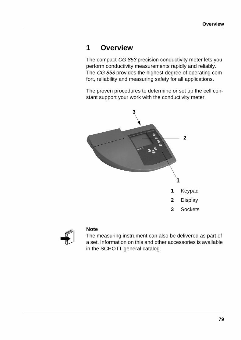
The compact CG 853 precision conductivity meter lets you perform conductivity measurements rapidly and reliably.The CG 853 provides the highest degree of operating com-fort, reliability and measuring safety for all applications.
The proven procedures to determine or set up the cell con-stant support your work with the conductivity meter.
NoteThe measuring instrument can also be delivered as part of a set. Information on this and other accessories is available in the SCHOTT general catalog.
1 Keypad
2 Display
3 Sockets
3
2
1
79

Overview
1.1 Keyboard
Measuring instrument ON/OFF <on/off>
Select measuring mode<ì>
Set up or determine cell constant; select temperature compensation <CAL>
Activate/deactivate AutoRead function <auto read>
Store measured value<STO>
Display/transmit measured values<RCL>
Reduce values, scroll <>
Confirm inputs, start AutoRead <run/enter>
Increase values, scroll<>
80

Overview
1.2 Display
1.3 Sockets
CautionOnly connect probes to the instrument that cannot feed ex-cessive voltages or currents (> SELV and > circuit with cur-rent limiter). Almost all commercial electrodes - especially SCHOTT electrodes - meet these requirements.
Connections:
1 8 pole socket with pin contacts
2 RS 232 interface/analog output
3 Plug-in power supply (optional)
Status line
Measured value display
Function and temperature display
1 2 3
81
Overview
1.4 Declaration of Conformity
29.03.99
SCHOTT Geräte GmbHIm Langgewann 5
D 65719 Hofheim am TaunusDeutschland, Germany, Allemagne
29. März, March 29rd, 29, Mars, 1999AGQSF0000-A059-00/990329
82
Overview
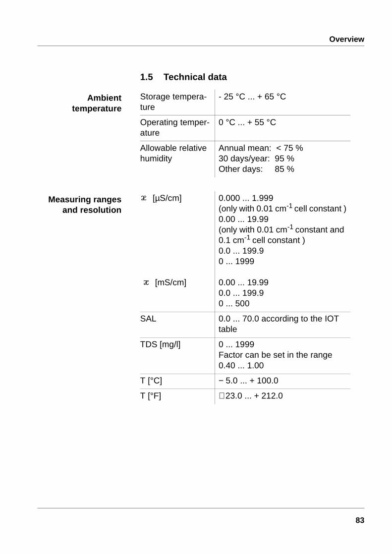
1.5 Technical data
Storage tempera-ture
- 25 °C ... + 65 °C
Operating temper-ature
0 °C ... + 55 °C
Allowable relative humidity
Annual mean: < 75 %30 days/year: 95 %Other days: 85 %
[µS/cm]
[mS/cm]
0.000 ... 1.999(only with 0.01 cm-1 cell constant )0.00 ... 19.99(only with 0.01 cm-1 constant and 0.1 cm-1 cell constant )0.0 ... 199.90 ... 1999
0.00 ... 19.990.0 ... 199.90 ... 500
SAL 0.0 ... 70.0 according to the IOT table
TDS [mg/l] 0 ... 1999 Factor can be set in the range0.40 ... 1.00
T [°C] − 5.0 ... + 100.0
T [°F] + 23.0 ... + 212.0
Ambienttemperature
Measuring rangesand resolution
83
Overview
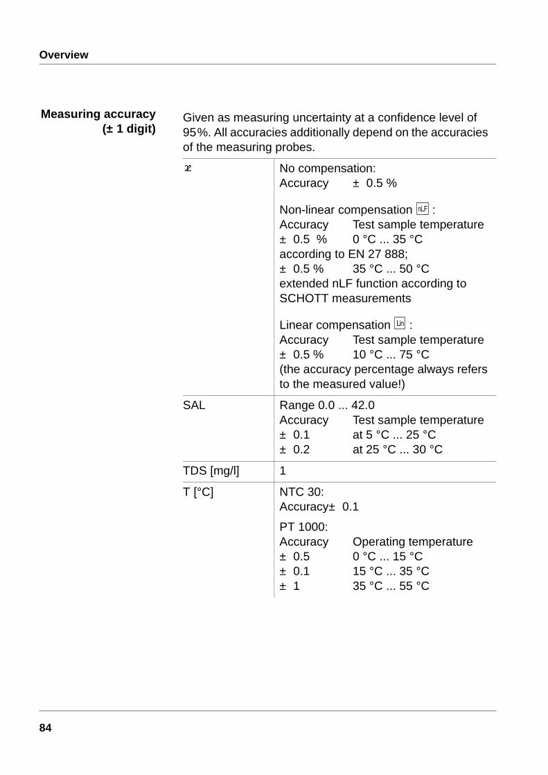
Given as measuring uncertainty at a confidence level of 95%. All accuracies additionally depend on the accuracies of the measuring probes.
No compensation:Accuracy ± 0.5 %
Non-linear compensation :Accuracy Test sample temperature± 0.5 % 0 °C ... 35 °C according to EN 27 888; ± 0.5 % 35 °C ... 50 °C extended nLF function according toSCHOTT measurements
Linear compensation :Accuracy Test sample temperature± 0.5 % 10 °C ... 75 °C(the accuracy percentage always refers to the measured value!)
SAL Range 0.0 ... 42.0Accuracy Test sample temperature± 0.1 at 5 °C ... 25 °C± 0.2 at 25 °C ... 30 °C
TDS [mg/l] 1
T [°C] NTC 30:Accuracy± 0.1
PT 1000:Accuracy Operating temperature± 0.5 0 °C ... 15 °C± 0.1 15 °C ... 35 °C± 1 35 °C ... 55 °C
Measuring accuracy(± 1 digit)
84

Overview
T [°F] NTC 30: Accuracy ± 0.2
PT 1000:Accuracy Operating temperature± 0.9 at 32 °F ... 59 °F ± 0.2 at 59 °F ... 95 °F± 1.8 at 95 °F ... 131 °F
C [cm-1] 0.010.10.250 ... 2.500
C [cm-1] 0.450 ... 0.5000.800 ... 1.200
TREF [°C] 2025
Manual [°C] - 5 ... +100
Length [mm] 240
Width [mm] 285
Height [mm] 85
Weight [kg] Approx. 1.1(without plug-in power supply unit)
Measuring accuracy(± 1 digit)
(Continuation)
Cell constant,to be set
Cell constant,calibrated
Reference tempera-ture, selectable
Temperature input
Dimensions andweight
85
Overview
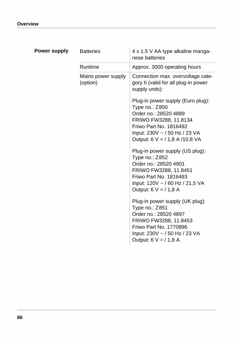
Batteries 4 x 1.5 V AA type alkaline manga-nese batteries
Runtime Approx. 3000 operating hours
Mains power supply(option)
Connection max. overvoltage cate-gory II (valid for all plug-in power supply units):
Plug-in power supply (Euro plug):Type no.: Z850Order no.: 28520 4889FRIWO FW3288, 11.8134Friwo Part No. 1816492Input: 230V ~ / 50 Hz / 23 VAOutput: 6 V = / 1,8 A /10,8 VA
Plug-in power supply (US plug):Type no.: Z852Order no.: 28520 4901FRIWO FW3288, 11.8451Friwo Part No. 1816493Input: 120V ~ / 60 Hz / 21,5 VAOutput: 6 V = / 1,8 A
Plug-in power supply (UK plug):Type no.: Z851Order no.: 28520 4897FRIWO FW3288, 11.8453Friwo Part No. 1770896Input: 230V ~ / 50 Hz / 23 VAOutput: 6 V = / 1,8 A
Power supply
86

Overview
Test marks TÜV GS, UL/CUL, CE
Display Multifunctional LCD
Keypad Foil keypad (Polyester)
Data storage Ring store for 200 value pairs, conductivity/salinity/TDS, temperature
Interference emis-sion (generic stan-dard)
EN 50081-1FCC class A
Interference immuni-ty (generic standard)
EN 50082-1
Protective class 3, EN 61010-1
Climatic class 2, VDI/VDE 3540
EMC andVDE norms
Automatic with Pt 1000/NTC (30 kW)
-5 ... 100,0 °C
Manual input -5 ... 100 °C resolution 1K
Measuring cell 8 pole socket with pin contacts
RS interface/analog output
Bidirectional RS 232 interface or analog output with autom. recogni-tion of the PC, printer, or recorder connected
Plug-in power supply (option)
2 pole special Friwo
Temperaturecompensation
Connectors
87

Overview
88
Safety
2 Safety
This operating manual contains basic instructions that you must follow during the commissioning, operation and main-tenance of the instrument. Consequently, all responsible personnel must read this operating manual before working with the instrument. The operating manual must always be available within the vicinity of the instrument.
Target group This measuring instrument was developed for use in the lab-oratory. Thus, we assume that, as a result of their professional train-ing and experience, the operators will know the necessary safety precautions to take when handling chemicals.
Symbols used
Cautionindicates instructions that have to be followed to prevent damage to your instrument.
Warningindicates instructions that have to be followed to protect yourself and the instrument from dangerous electrical volt-age.
NoteIndicates notes that draw your attention to special features.
NoteIndicates cross-references to other documents, e.g. appli-cation reports, operating manuals of measuring cells, etc.
89
Safety
2.1 Authorized useThis instrument is authorized exclusively for measuring the conductivity, salinity, temperature and TDS (total dissolved solids) in the laboratory. The technical specifications as given in the section 1.5 TECHNICAL DATA, must be observed. Only the operation and running of the measuring instrument according to the in-structions given in this operating manual is authorized.Any other use is considered unauthorized.
2.2 General safety instructionsThis instrument is constructed and tested in compliance with the EN 61010-1 safety regulations for electronic measuring instruments. It left the factory in a safe and secure technical condition.
Function and opera-tional safety
The smooth functioning and operational safety of the instru-ment can only be guaranteed if the generally applicable safety measures and the specific safety instructions in this operating manual are followed.
The smooth functioning and operational safety of the instru-ment can only be guaranteed under the climatic conditions specified in the section 1.5 TECHNICAL DATA.
If the instrument was transported from a cold environment to a warm environment, the formation of condensate can lead to the faulty functioning of the instrument. In this event, wait until the temperature of the instrument reaches room tem-perature before putting the instrument back into operation.
CautionThe instrument is only allowed to be opened by personnel authorized by SCHOTT.
90

Safety
Safe operation If safe operation is no longer possible, the instrument must be taken out of service and secured against inadvertent op-eration.Safe operation is no longer possible if:
l the instrument has been damaged in transport
l the instrument has been stored under adverse conditions for a lengthy period of time
l the instrument is visibly damaged
l the instrument no longer operates as described in this manual
If you are in doubt contact the supplier of the instrument.
Obligations of theoperator
The operator of this measuring instrument must ensure that the following laws and guidelines are observed when using dangerous substances:
l EEC directives for protective labor legislation
l National protective labor legislation
l Safety regulations
l Safety datasheets of the chemical manufacturer.
91
Safety
92

Commissioning
3 Commissioning
Perform the following activities for initial comissioning:
l Set the date and time
l Connect the plug-in power supply (option).
1 Press and hold down the <ì> key.
2 Press the <on/off> key.The display test appears briefly on the display.The measuring instrument then switches automati-cally to the setting of the baud rate.
3 Press the <run/enter> key repeatedly until the date flashes on the display.
4 Set today’s date by pressing <> <>.
5 Confirm with <run/enter>.The date (month) flashes on the display.
6 Set the current month by pressing <> <>.
7 Confirm with <run/enter>. The year appears on the display.
8 Set the current year by pressing <> <>.
9 Confirm with <run/enter>.The hour field flashes on the display.
10 Set the current time by pressing <> <>.
11 Confirm with <run/enter>.The minutes field flashes on the display.
12 Set the current time by pressing <> <>.
13 Confirm with <run/enter>. The measuring instrument then switches to the measuring mode.
14 Switch off the instrument by pressing <on/off>.
Setting the dateand time
93
Commissioning
Connecting theplug-in power
supply (optional)
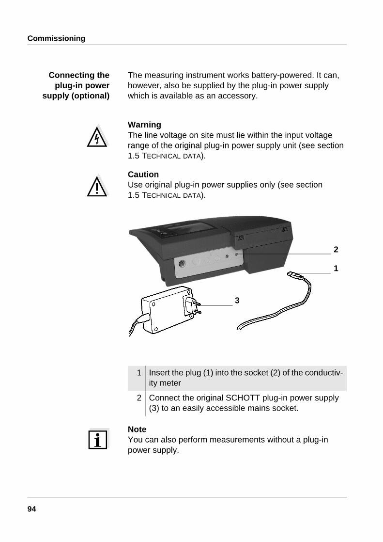
The measuring instrument works battery-powered. It can, however, also be supplied by the plug-in power supply which is available as an accessory.
WarningThe line voltage on site must lie within the input voltage range of the original plug-in power supply unit (see section 1.5 TECHNICAL DATA).
CautionUse original plug-in power supplies only (see section 1.5 TECHNICAL DATA).
NoteYou can also perform measurements without a plug-in power supply.
1 Insert the plug (1) into the socket (2) of the conductiv-ity meter
2 Connect the original SCHOTT plug-in power supply (3) to an easily accessible mains socket.
1
2
3
94

Operation
4 Operation
4.1 Switch on the instrument
NoteThe instrument has an energy saving feature to avoid unnecessary battery depletion. The energy saving feature switches the instrument off if no key has been pressed for an hour.The energy saving feature is not active:
l if the power is supplied by the plug-in power supply
l if the AutoStore function is active
l if a PC is connected
l if the recorder cable is connected
l if the printer cable is connected(for external printers)
1 Place the instrument on a flat surface and protect it against intense light and heat.
2 Connect the conductivity measuring cell to the instru-ment.
3 Press the <on/off> key.The display test appears briefly on the display.The instrument then switches automatically to the previously selected measuring mode.
4 Check or determine the cell constant [C]. The proce-dure is described in section 4.3, on page 103.
95
Operation
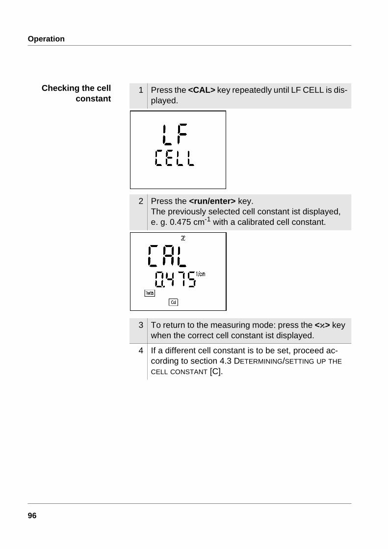
Checking the cellconstant
1 Press the <CAL> key repeatedly until LF CELL is dis-played.
2 Press the <run/enter> key. The previously selected cell constant ist displayed, e. g. 0.475 cm-1 with a calibrated cell constant.
3 To return to the measuring mode: press the <ì> key when the correct cell constant ist displayed.
4 If a different cell constant is to be set, proceed ac-cording to section 4.3 DETERMINING/SETTING UP THE CELL CONSTANT [C].
96

Operation
4.2 MeasuringPreparatory
activitiesPerform the following activities when you want to measure:
CautionWhen connecting an earthed PC/printer, measurements cannot be performed in earthed media as incorrect values would result.The RS232 interface is not galvanically isolated.
Temperature probe Measurements can be performed with and without a temper-ature probe. A connected temperature probe is indicated by TP on the display. If you want to use a SCHOTT conductivity measuring cell without a temperature probe, you have to connect it with an adapter (available at SCHOTT).
NoteThe conductivity meter automatically recognizes the type of the temperature probe used. As a result, you can connect electrodes with the NTC30 or Pt1000.
The temperature measurement is absolutely essential for a reproducible conductivity measurement. If the measure-ment is made without a temperature probe, proceed as fol-lows:
1 Connect the measuring cell to the instrument.
2 Adjust the temperature of the test solutions or mea-sure the current temperature if the measurement is made without a temperature probe.
3 Calibrate the instrument with the measuring cell or check the cell constant set up.
4 Select the measuring mode by pressing <ì>.
1 Determine the current temperature using a thermom-eter.
2 Set up the temperature by pressing <> <>.
97
Operation
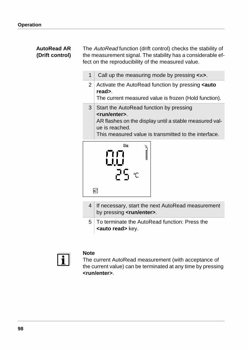
AutoRead AR(Drift control)
The AutoRead function (drift control) checks the stability of the measurement signal. The stability has a considerable ef-fect on the reproducibility of the measured value.
NoteThe current AutoRead measurement (with acceptance of the current value) can be terminated at any time by pressing <run/enter>.
1 Call up the measuring mode by pressing <ì>.
2 Activate the AutoRead function by pressing <auto read>.The current measured value is frozen (Hold function).
3 Start the AutoRead function by pressing <run/enter>.AR flashes on the display until a stable measured val-ue is reached.This measured value is transmitted to the interface.
4 If necessary, start the next AutoRead measurement by pressing <run/enter>.
5 To terminate the AutoRead function: Press the <auto read> key.
98
Operation
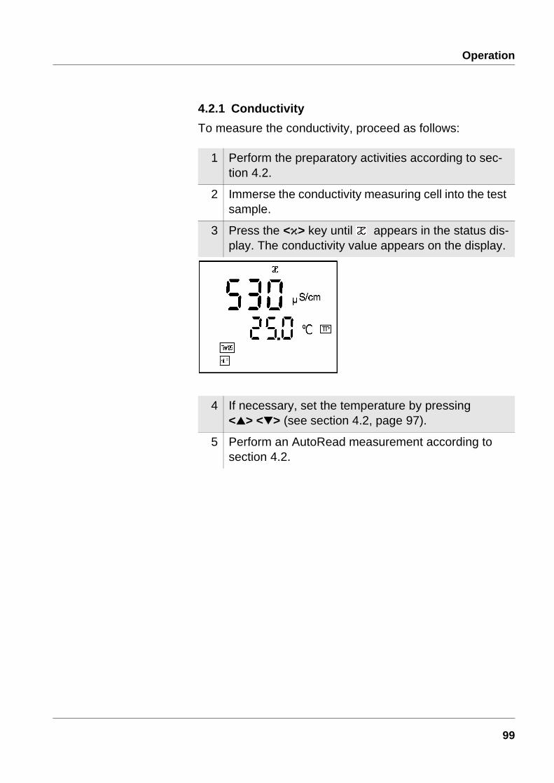
4.2.1 Conductivity
To measure the conductivity, proceed as follows:
1 Perform the preparatory activities according to sec-tion 4.2.
2 Immerse the conductivity measuring cell into the test sample.
3 Press the <ì> key until appears in the status dis-play. The conductivity value appears on the display.
4 If necessary, set the temperature by pressing <> <> (see section 4.2, page 97).
5 Perform an AutoRead measurement according to section 4.2.
99
Operation
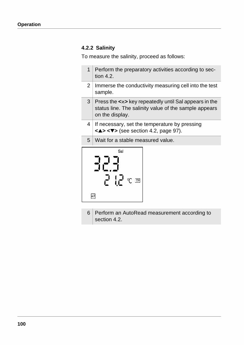
4.2.2 Salinity
To measure the salinity, proceed as follows:
1 Perform the preparatory activities according to sec-tion 4.2.
2 Immerse the conductivity measuring cell into the test sample.
3 Press the <ì> key repeatedly until Sal appears in the status line. The salinity value of the sample appears on the display.
4 If necessary, set the temperature by pressing <> <> (see section 4.2, page 97).
5 Wait for a stable measured value.
6 Perform an AutoRead measurement according to section 4.2.
100
Operation
4.2.3 TDS (total dissolved solids)
To measure the TDS, proceed as follows:
1 Perform the preparatory activities according to sec-tion 4.2.
2 Immerse the conductivity measuring cell into the test sample.
3 When measuring with an integrated temperature probe continue with step 4.When measuring without temperature probe:
– Determine the temperature of the test sample using a thermometer
– Press the <ì> key repeatedly until appears in the status line
– Enter the temperature using <> <>.
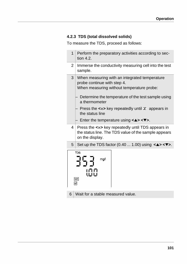
4 Press the <ì> key repeatedly until TDS appears in the status line. The TDS value of the sample appears on the display.
5 Set up the TDS factor (0.40 ... 1.00) using <> <>.
6 Wait for a stable measured value.
101
Operation
4.2.4 Transmitting measured values
You can transmit measured values (data records) in 3 ways:
l Switch on the data transmission (Int 2) (see page 125)
– After expiry of the selected interval, the current data record is sent to the interface.
l Switch on AutoStore (Int 1) (see page 116)
– After expiry of the selected interval, the current data record is sent to the interface and in addition is stored in the data store of the instrument
– AutoStore (Int 1) covers the data transmission interval (Int 2).
l Press the <run/enter> keyThis manually transmits the current measured values at any time - independently of the selected intervals.
NoteIf you connect a recorder (analog output), the output to the digital output is switched off.
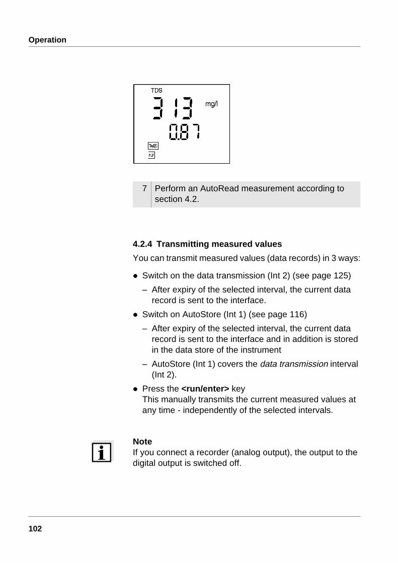
7 Perform an AutoRead measurement according to section 4.2.
102
Operation
4.3 Determining/setting up the cell constant [C]Why determine/set
up the cellconstant?
Due to ageing, the cell constant slightly changes. As a result, an inexact measured value is displayed. Calibration determines the current value of the cell constant and stores this value in the instrument. Thus, you should calibrate at regular intervals.
You can determine the cell constant of the conductivity mea-suring cell in the range 0.450 ... 0.500 cm-1 or 0,800 ... 1,200 cm-1 by calibrating in the control standard or set it up manually in the range 0.250... 2.500 cm-1. Additionally, you can select one of the fixed cell constants 0.1 cm-1 or 0.01 cm-1.
Determining the cellconstant
(calibration incontrol standard)
Determine the cell constant as follows:
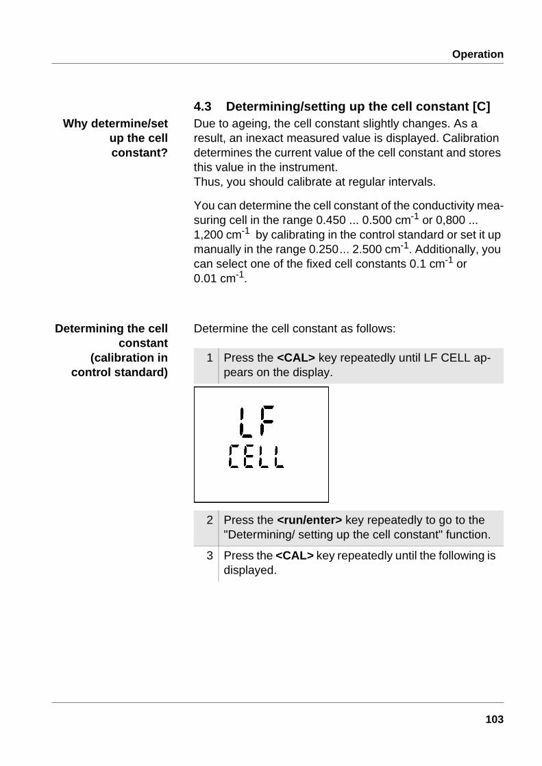
1 Press the <CAL> key repeatedly until LF CELL ap-pears on the display.
2 Press the <run/enter> key repeatedly to go to the "Determining/ setting up the cell constant" function.
3 Press the <CAL> key repeatedly until the following is displayed.
103
Operation
NoteIf error message appears see chapter 6 WHAT TO DO IF...
AutoRead During calibrating, the AutoRead function is automatically activated. The AR display flashes. The calibration procedure is finished when the AR display stops flashing.
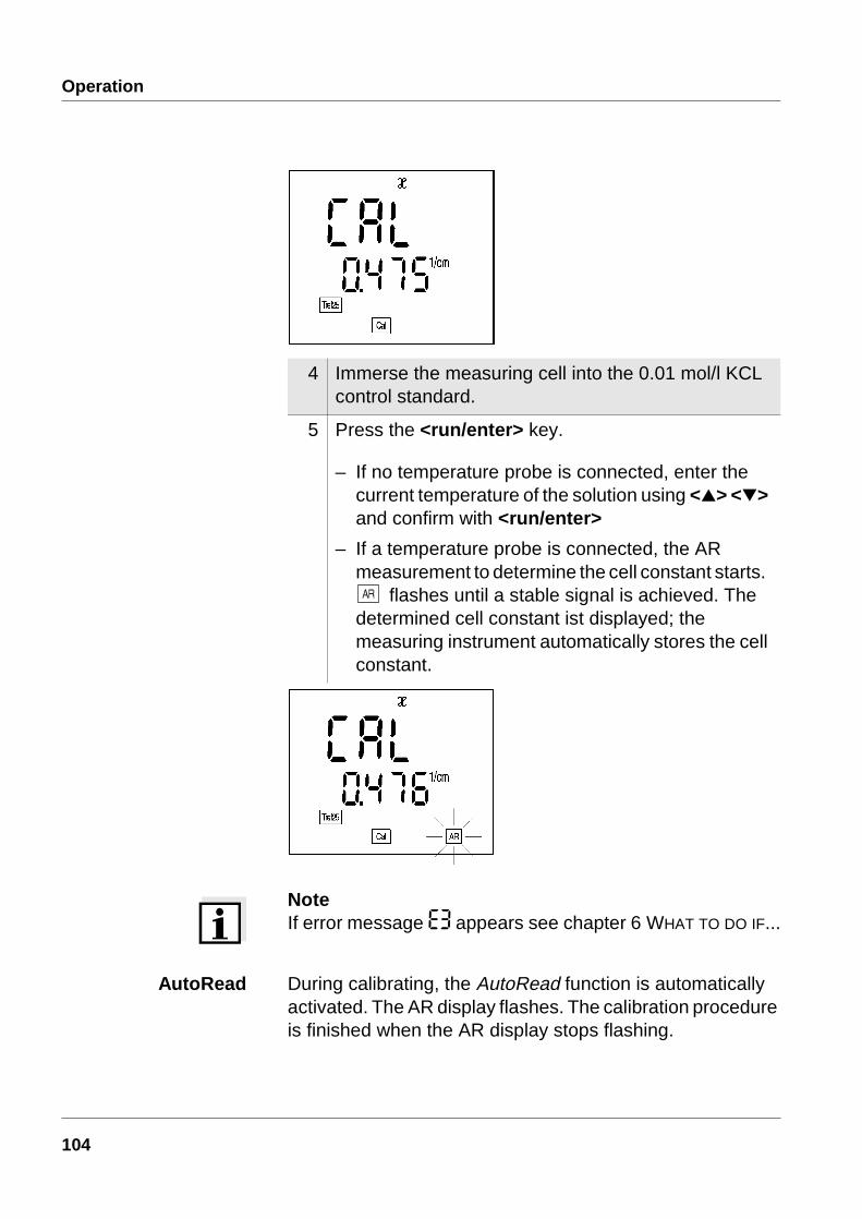
4 Immerse the measuring cell into the 0.01 mol/l KCL control standard.
5 Press the <run/enter> key.
– If no temperature probe is connected, enter the current temperature of the solution using <> <> and confirm with <run/enter>
– If a temperature probe is connected, the AR measurement to determine the cell constant starts.
flashes until a stable signal is achieved. The determined cell constant ist displayed; the measuring instrument automatically stores the cell constant.
104
Operation
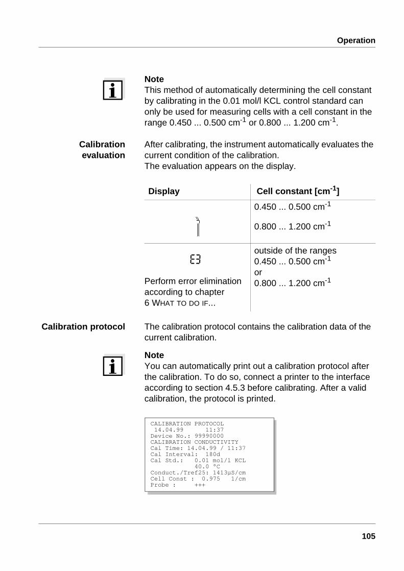
NoteThis method of automatically determining the cell constant by calibrating in the 0.01 mol/l KCL control standard can only be used for measuring cells with a cell constant in the range 0.450 ... 0.500 cm-1 or 0.800 ... 1.200 cm-1.
Calibrationevaluation
After calibrating, the instrument automatically evaluates the current condition of the calibration. The evaluation appears on the display.
Calibration protocol The calibration protocol contains the calibration data of the current calibration.
NoteYou can automatically print out a calibration protocol after the calibration. To do so, connect a printer to the interface according to section 4.5.3 before calibrating. After a valid calibration, the protocol is printed.
Display Cell constant [cm-1]
0.450 ... 0.500 cm-1
0.800 ... 1.200 cm-1
Perform error elimination according to chapter 6 WHAT TO DO IF...
outside of the ranges0.450 ... 0.500 cm-1
or0.800 ... 1.200 cm-1
CALIBRATION PROTOCOL 14.04.99 11:37Device No.: 99990000CALIBRATION CONDUCTIVITYCal Time: 14.04.99 / 11:37Cal Interval: 180dCal Std.: 0.01 mol/l KCL 40.0 °CConduct./Tref25: 1413µS/cmCell Const : 0.975 1/cmProbe : +++
105
Operation
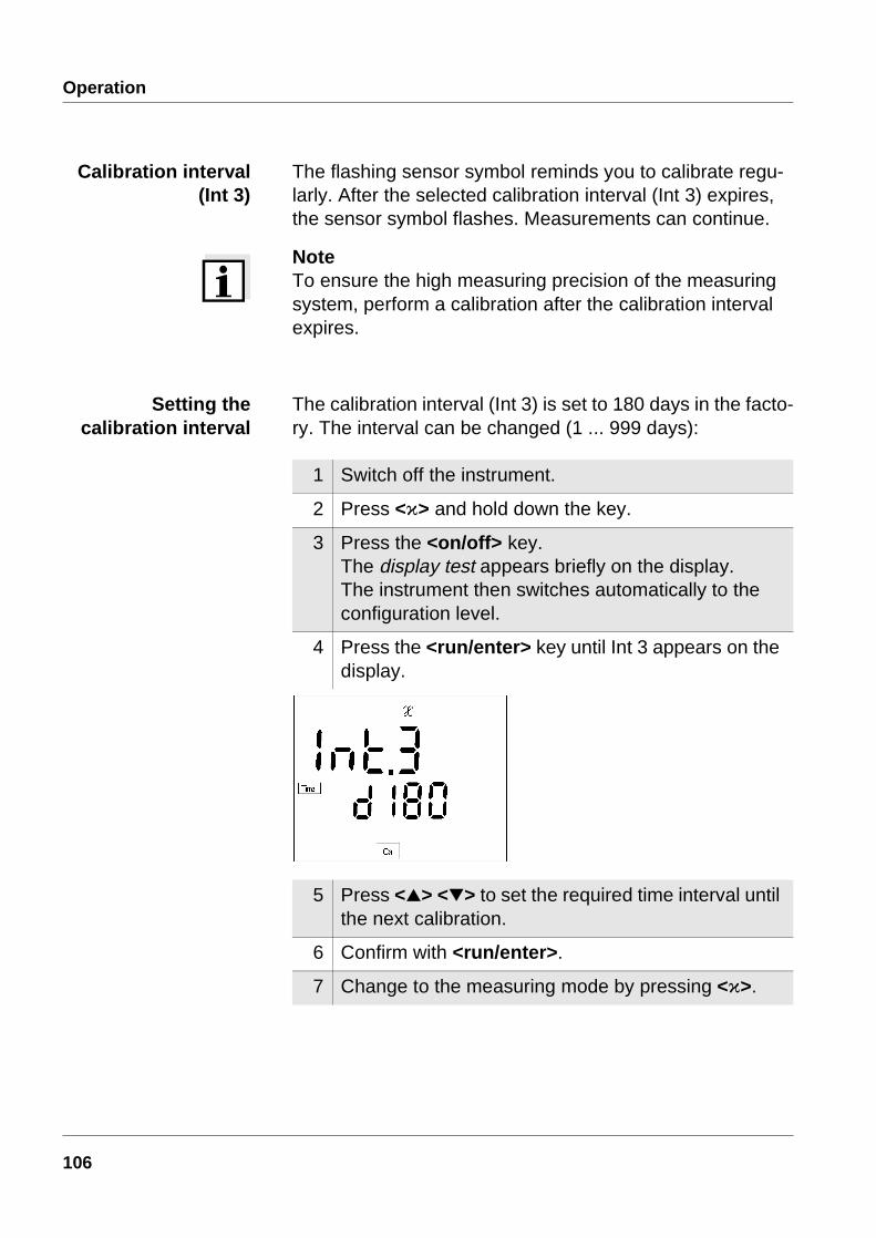
Calibration interval(Int 3)
The flashing sensor symbol reminds you to calibrate regu-larly. After the selected calibration interval (Int 3) expires, the sensor symbol flashes. Measurements can continue.
NoteTo ensure the high measuring precision of the measuring system, perform a calibration after the calibration interval expires.
Setting thecalibration interval
The calibration interval (Int 3) is set to 180 days in the facto-ry. The interval can be changed (1 ... 999 days):
1 Switch off the instrument.
2 Press <ì> and hold down the key.
3 Press the <on/off> key.The display test appears briefly on the display.The instrument then switches automatically to the configuration level.
4 Press the <run/enter> key until Int 3 appears on the display.
5 Press <> <> to set the required time interval until the next calibration.
6 Confirm with <run/enter>.
7 Change to the measuring mode by pressing <ì>.
106

Operation
Setting up the cellconstant manually
To set up the cell constant manually, proceed as follows:
Note
1 Press the <CAL> key repeatedly until LF CELL ap-pears on the display.
2 Press the <run/enter> key.
3 Press the <CAL> key repeatedly until the cell con-stant to be set, e. g. 0.475 cm-1 is displayed.
4 Set up the cell constant to be used by pressing <> <>, e. g. 0.614 cm-1.
5 To return to the measuring mode: press the <ì> key.
107

Operation
The cell constant to be set up must either be taken from the operating manual of the measuring cell or is printed on the measuring cell.
Selecting the
0.1 cm-1
cell constant
To select the 0.1 cm-1 cell constant proceed as follows:
1 Press the <CAL> key repeatedly until LF CELL ap-pears on the display.
2 Press the <run/enter> key.
3 Press the <CAL> key repeatedly until the 0.100 cm-1 cell constant appears on the display.
4 To return to the measuring mode: press the <ì> key.
108

Operation
Selecting the
0.01 cm-1
cell constant
To select the 0.01 cm-1 cell constant proceed as follows:
1 Press the <CAL> key repeatedly until LF CELL ap-pears on the display.
2 Press the run/enter> key.
3 Press the <CAL> key repeatedly until the 0.010 cm-1 cell constant appears on the display.
4 To return to the measuring mode: press the <ì> key.
109
Operation
Setting up the temperature
compensation TC
The calculation of the temperature compensation is based on the preset reference temperature, Tref 20 or Tref 25 (see section 4.6 CONFIGURATION).
You can select one of the following temperature compensa-tions:
l Non-linear temperature compensation "nLF"according to DIN 38404 or EN 27 888
l linear temperature compensation "Lin" with a coefficient that can be set in the range 0.001 ... 3.000 %/K
l no temperature compensation
Noteips Select the following temperature compensations to work
with the test samples given in the table:
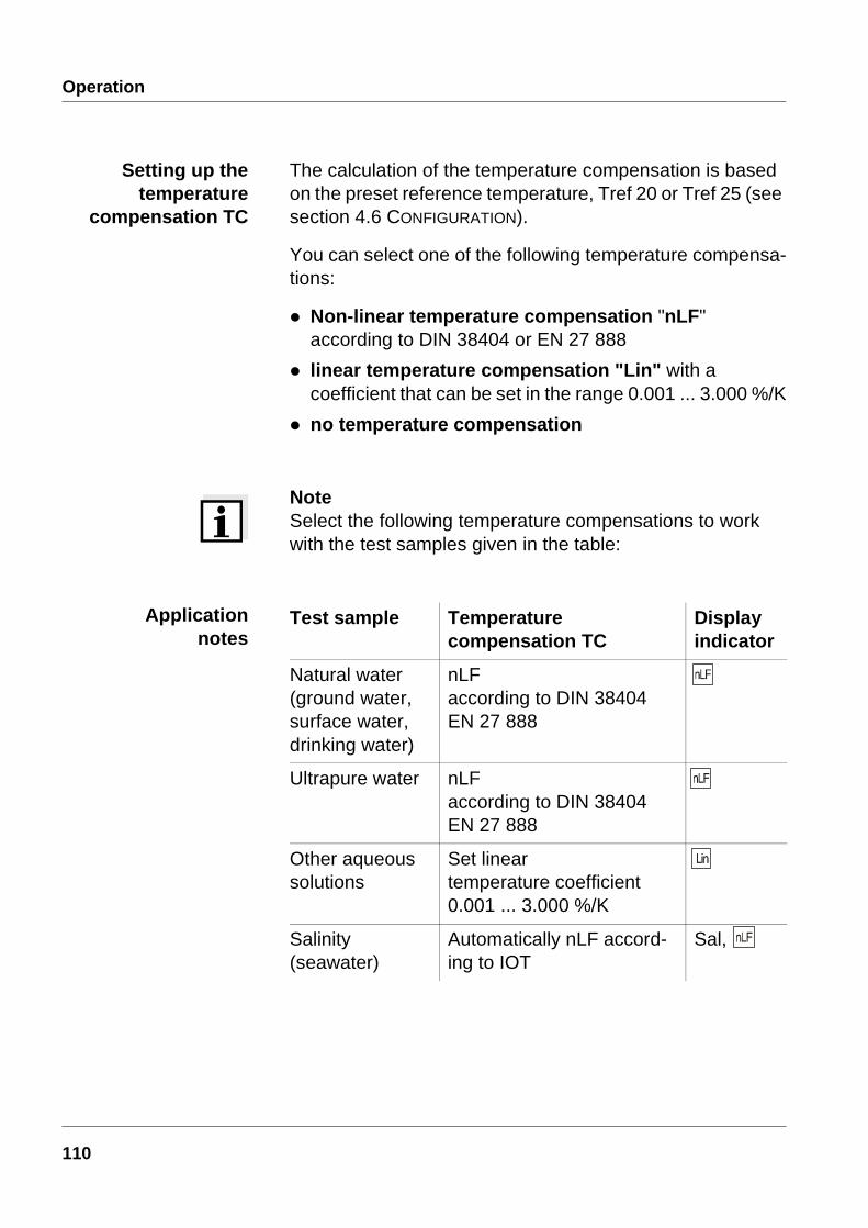
Applicationnotes
Test sample Temperature compensation TC
Display indicator
Natural water (ground water, surface water, drinking water)
nLFaccording to DIN 38404EN 27 888
Ultrapure water nLFaccording to DIN 38404EN 27 888
Other aqueous solutions
Set linear temperature coefficient0.001 ... 3.000 %/K
Salinity (seawater)
Automatically nLF accord-ing to IOT
Sal,
110
Operation
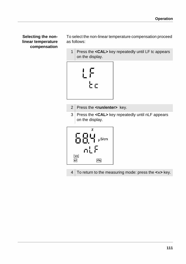
Selecting the non-linear temperature
compensation
To select the non-linear temperature compensation proceed as follows:
1 Press the <CAL> key repeatedly until LF tc appears on the display.
2 Press the <run/enter> key.
3 Press the <CAL> key repeatedly until nLF appears on the display.
4 To return to the measuring mode: press the <ì> key.
111
Operation
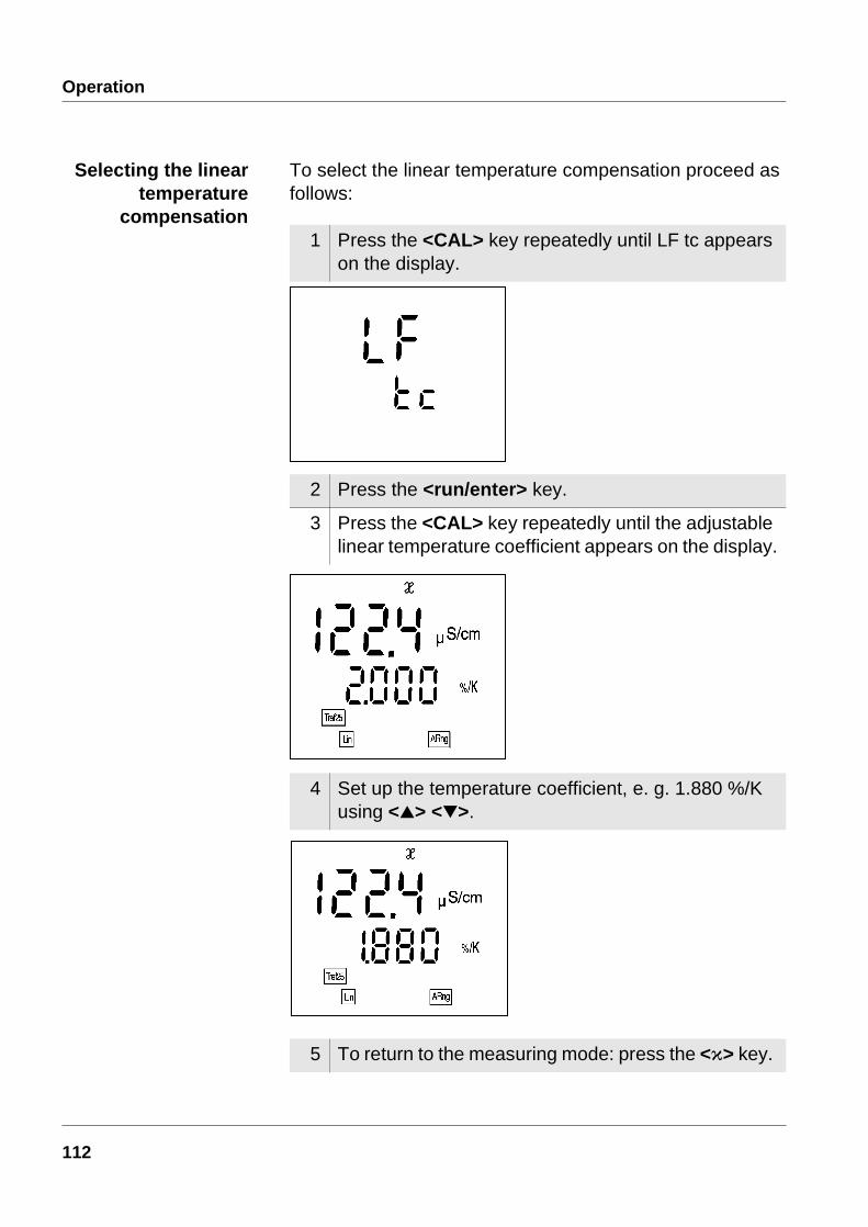
Selecting the lineartemperature
compensation
To select the linear temperature compensation proceed as follows:
1 Press the <CAL> key repeatedly until LF tc appears on the display.
2 Press the <run/enter> key.
3 Press the <CAL> key repeatedly until the adjustable linear temperature coefficient appears on the display.
4 Set up the temperature coefficient, e. g. 1.880 %/K using <> <>.
5 To return to the measuring mode: press the <ì> key.
112

Operation
Switching off thetemperature
compensation
To switch off the temperature compensation proceed as fol-lows:
1 Press the <CAL> key repeatedly until LF tc appears on the display.
2 Press the <run/enter> key.
3 Press the <CAL> key repeatedly until the following display appears.
4 The temperature compensation has been switched off.
5 To return to the measuring mode: press the <ì> key.
113

Operation
4.4 StoringThe conductivity meter has an internal data storage device. Up to 200 data records can be stored in it. A complete data record consists of:
l Memory location
l Date
l Time
l Measured value
l Temperature
l I.D. number
You can transmit measured values (data records) to the data storage in 2 ways:
l Manual storage
l Switching on the AutoStore function (Int 1), see page 116.
4.4.1 Manual storage
You can transmit a measured value to the data storage as follows:
1 Press the <STO> key.The current number of the next free memory location appears on the display.
114
Operation
*(+,, message This message appears if all 200 memory locations are full.
You have the following options:
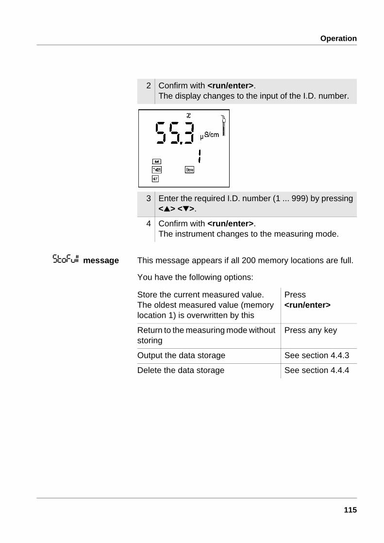
2 Confirm with <run/enter>.The display changes to the input of the I.D. number.
3 Enter the required I.D. number (1 ... 999) by pressing<> <>.
4 Confirm with <run/enter>.The instrument changes to the measuring mode.
Store the current measured value. The oldest measured value (memory location 1) is overwritten by this
Press <run/enter>
Return to the measuring mode without storing
Press any key
Output the data storage See section 4.4.3
Delete the data storage See section 4.4.4
115
Operation
4.4.2 Switching on AutoStore (Int 1)
The storage interval (Int 1) determines the time interval between automatic storage processes. After the time interval expires, the current data record is transmitted to the data storage and to the interface.
The storage interval (Int 1) is set to OFF in the factory. Thus, the AutoStore function is switched off. To switch the function on, set up a time interval (5 s, 10 s, 30 s, 1 min, 5 min, 10 min, 15 min, 30 min, 60 min).
NoteIf the AutoStore function is active, the setting of the data transmission interval (int 2) is ineffective (see page 125).
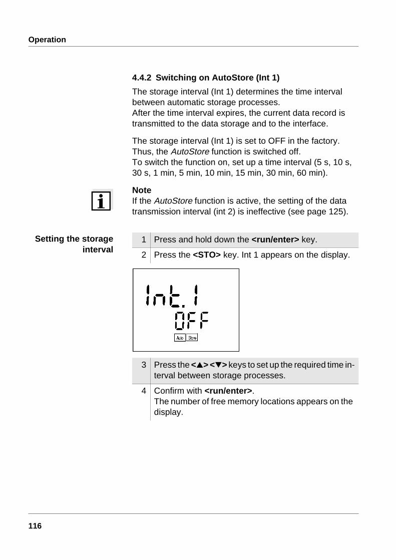
1 Press and hold down the <run/enter> key.
2 Press the <STO> key. Int 1 appears on the display.
3 Press the <> <> keys to set up the required time in-terval between storage processes.
4 Confirm with <run/enter>.The number of free memory locations appears on the display.
Setting the storageinterval
116

Operation
5 As soon as all 200 memory locations are full, the Au-toStore function is terminated (Int 1 = OFF). If too few storage locations are available for your measurements:
– backup the data storage (see page 118) and
– clear the data stored (see page 124).
6 Confirm with <run/enter>.The prompt for the I.D. number appears on the dis-play.
7 Press <> <> to set the required I.D. number.
8 Confirm with <run/enter>.The instrument changes to the measuring mode and starts the measuring and storage procedure.AutoStore flashes on the display.
117
Operation
NoteThe AutoStore function is interrupted if you perform other functions, e.g. output data storage. After completing the other function, the AutoStore function continues. However, as a result, gaps can occur in the recording of the measured values.
Switching off theAutoStore
Switch off the AutoStore function by:
l Setting the storage interval (Int 1) to OFF or
l Switch the conductivity meter off and on again.
4.4.3 Outputting the data storage
The contents of the data storage can be output to the:
l display
l interface
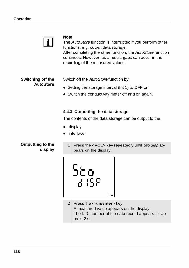
1 Press the <RCL> key repeatedly until Sto disp ap-pears on the display.
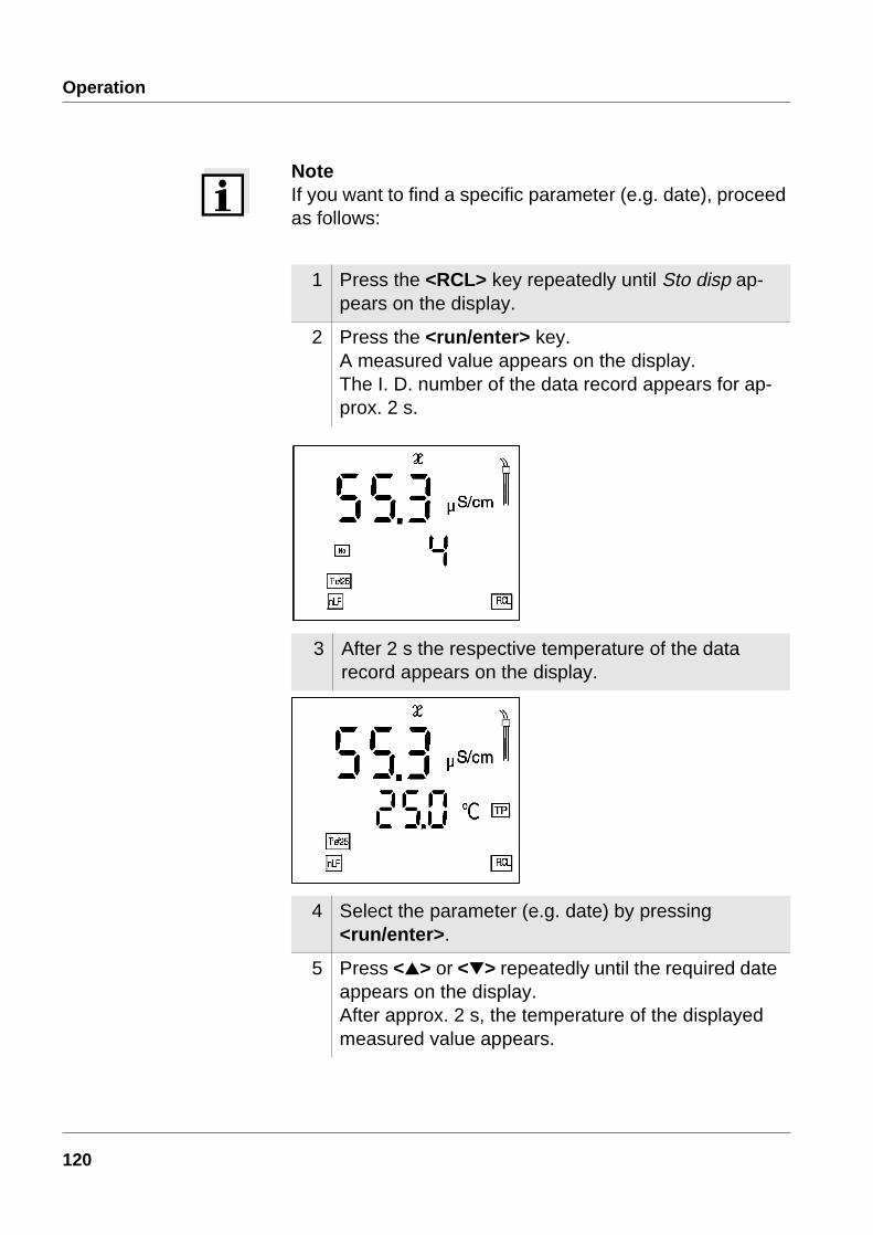
2 Press the <run/enter> key. A measured value appears on the display. The I. D. number of the data record appears for ap-prox. 2 s.
Outputting to thedisplay
118

Operation
You can perform the following activities:
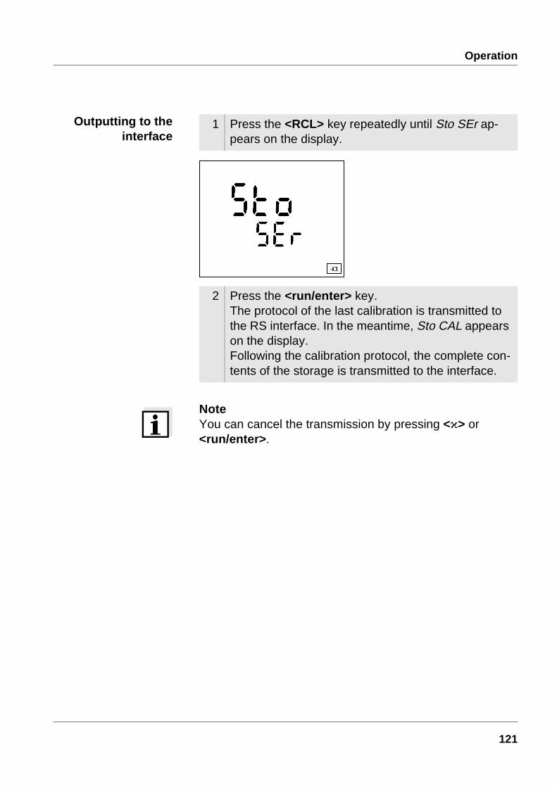
3 After 2 s the respective temperature of the data record appears on the display. Stored data records are displayed together with the RCL display indica-tor.
Display further parameters of the data record (I.D. no., date, time, memory loca-tion)
Press <run/enter>
Advance one data record (memory loca-tion)
Press <>
Go back one data record (memory loca-tion)
Press <>
119
Operation
NoteIf you want to find a specific parameter (e.g. date), proceed as follows:
1 Press the <RCL> key repeatedly until Sto disp ap-pears on the display.
2 Press the <run/enter> key. A measured value appears on the display. The I. D. number of the data record appears for ap-prox. 2 s.
3 After 2 s the respective temperature of the data record appears on the display.
4 Select the parameter (e.g. date) by pressing <run/enter>.
5 Press <> or <> repeatedly until the required date appears on the display. After approx. 2 s, the temperature of the displayed measured value appears.
120
Operation
NoteYou can cancel the transmission by pressing <ì> or <run/enter>.
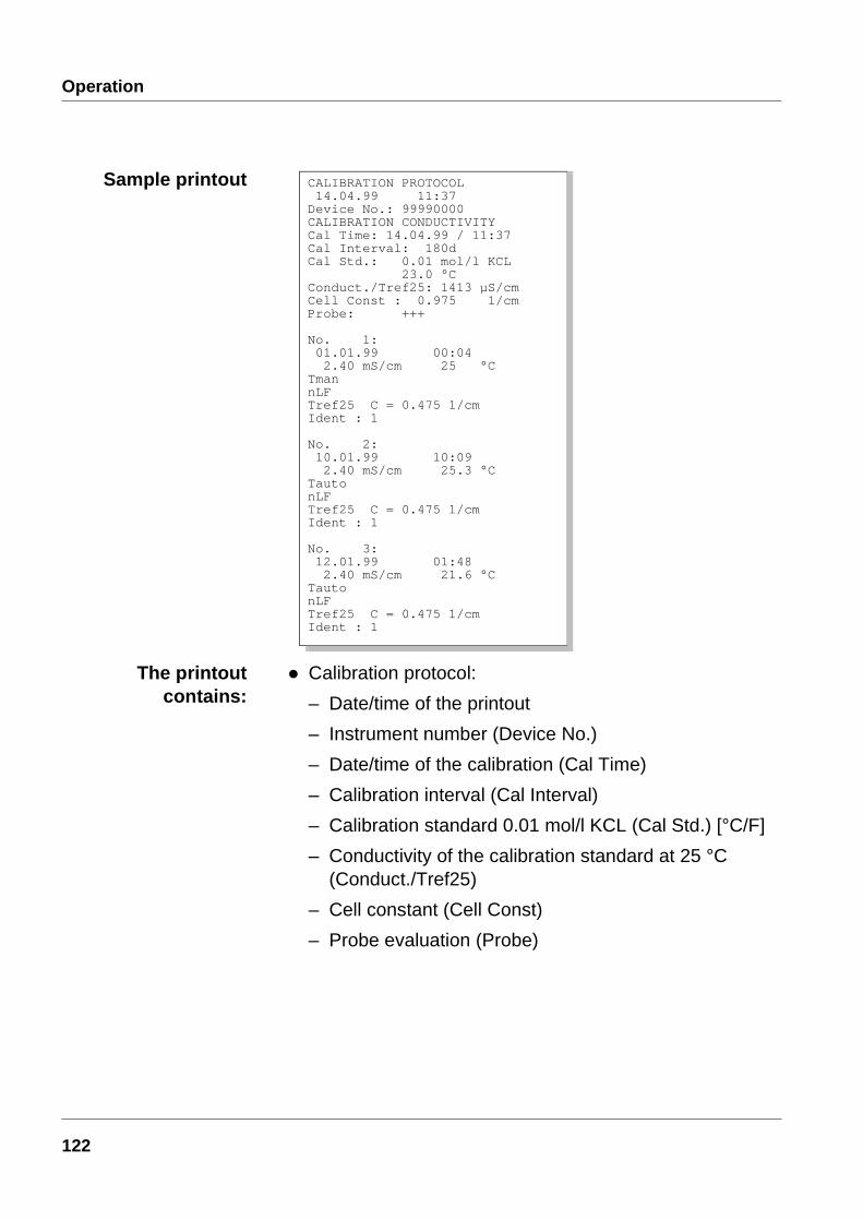
1 Press the <RCL> key repeatedly until Sto SEr ap-pears on the display.
2 Press the <run/enter> key. The protocol of the last calibration is transmitted to the RS interface. In the meantime, Sto CAL appears on the display. Following the calibration protocol, the complete con-tents of the storage is transmitted to the interface.
Outputting to theinterface
121
Operation
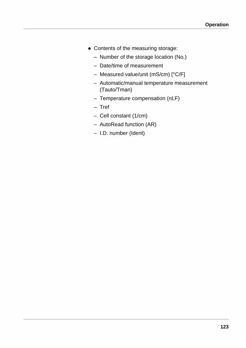
The printoutcontains:
l Calibration protocol:
– Date/time of the printout
– Instrument number (Device No.)
– Date/time of the calibration (Cal Time)
– Calibration interval (Cal Interval)
– Calibration standard 0.01 mol/l KCL (Cal Std.) [°C/F]
– Conductivity of the calibration standard at 25 °C(Conduct./Tref25)
– Cell constant (Cell Const)
– Probe evaluation (Probe)
Sample printout CALIBRATION PROTOCOL 14.04.99 11:37Device No.: 99990000CALIBRATION CONDUCTIVITYCal Time: 14.04.99 / 11:37Cal Interval: 180dCal Std.: 0.01 mol/l KCL 23.0 °CConduct./Tref25: 1413 µS/cmCell Const : 0.975 1/cmProbe: +++
No. 1: 01.01.99 00:04 2.40 mS/cm 25 °CTman nLFTref25 C = 0.475 1/cmIdent : 1
No. 2: 10.01.99 10:09 2.40 mS/cm 25.3 °CTauto nLFTref25 C = 0.475 1/cmIdent : 1
No. 3: 12.01.99 01:48 2.40 mS/cm 21.6 °CTauto nLFTref25 C = 0.475 1/cmIdent : 1
122
Operation
l Contents of the measuring storage:
– Number of the storage location (No.)
– Date/time of measurement
– Measured value/unit (mS/cm) [°C/F]
– Automatic/manual temperature measurement(Tauto/Tman)
– Temperature compensation (nLF)
– Tref
– Cell constant (1/cm)
– AutoRead function (AR)
– I.D. number (Ident)
123
Operation
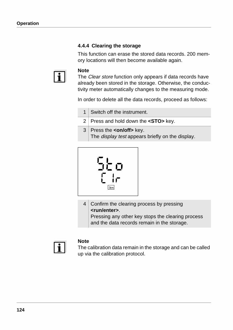
4.4.4 Clearing the storage
This function can erase the stored data records. 200 mem-ory locations will then become available again.
NoteThe Clear store function only appears if data records have already been stored in the storage. Otherwise, the conduc-tivity meter automatically changes to the measuring mode.
In order to delete all the data records, proceed as follows:
NoteThe calibration data remain in the storage and can be called up via the calibration protocol.
1 Switch off the instrument.
2 Press and hold down the <STO> key.
3 Press the <on/off> key.The display test appears briefly on the display.
4 Confirm the clearing process by pressing <run/enter>.Pressing any other key stops the clearing process and the data records remain in the storage.
124

Operation
4.5 Data transmissionYou can use the following options to transmit data:
l One of the following options:
– The AutoStore function (page 116) is used to periodically (Int 1 storage interval) save measured values internally and output them on the interface.
– The data transmission interval (Int 2) function is used to periodically output measured values to the interface (see below).
l The Output data store function (page 118) is used to out-put calibration data and stored measured values to the in-terface.
l The analog recorder output (page 127) is used to output measured values as voltages.
4.5.1 Data transmission interval (Int 2)
The interval for the data transmission (Int 2) determines the time interval between automatic data transmissions. After the time interval expires, the current data record is transmit-ted to the RS interface.
NoteThe setting of the interval (Int 2) only has an effect when the storage interval (AutoStore function) is switched off.
125

Operation
Setting thedata transmission
interval
The interval is set to OFF in the factory. To start the data transmission, set up an interval (5 s, 10 s, 30 s, 1 min, 5 min, 10 min, 15 min, 30 min, 60 min):
NoteIf the AutoStore function is active, the data transmission is performed according to the setting of the storage interval (Int1). Set the storage interval (Int1) to OFF to activate the data transmission interval (Int2).
NoteYou can also set the data transmission interval (Int2) in the Configuration menu (see page 125).
1 Press and hold down the <run/enter> key.
2 Press the <auto read> key.Int 2 appears on the display.
3 Press <> <> to set up the required time interval be-tween storage processes.
4 Confirm with <run/enter>. The instrument changes automatically to the measur-ing mode.
126

Operation
4.5.2 Recorder (analog output)
You can transmit the data to a recorder via the analog out-put. Connect the analog output to the recorder via the Z394 interface cable. The data output switches automatically to recorder output.
NoteActivate the analog output by connecting 2 and 3 or use the original cable.
The signal range of the analog output depends on the mea-sured parameter and the measuring range:
Measuring range Voltage Resolution
0.000 ... 1.999 µS/cm 0 ... 1999 mV 1 mV
0.00 ... 19.99 µS/cm 0 ... 1999 mV 1 mV
0.0 ... 199.9 µS/cm 0 ... 1999 mV 1 mV
0 ... 1999 µS/cm 0 ... 1999 mV 1 mV
0.00 ... 19.99 mS/cm 0 ... 1999 mV 1 mV
0.0 ... 199.9 mS/cm 0 ... 1999 mV 1 mV
0 ... 500 mS/cm 0 ... 500 mV 1 mV
Measuring range Voltage Resolution
0 ... 70.0 0 ... 700 mV 1 mV
Measuring range Voltage Resolution
0 ... 1999 mg/l 0 ... 1999 mV 1 mV
Socket assignment 1 Free2 Plug coding3 Ground4 Analog output
(Internal resistance < 5 Ohm)
Conductivity/resistance
Salinity
TDS
127
Operation
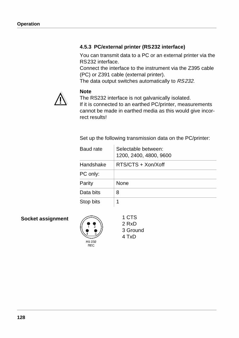
4.5.3 PC/external printer (RS232 interface)
You can transmit data to a PC or an external printer via the RS232 interface. Connect the interface to the instrument via the Z395 cable (PC) or Z391 cable (external printer). The data output switches automatically to RS232.
NoteThe RS232 interface is not galvanically isolated. If it is connected to an earthed PC/printer, measurements cannot be made in earthed media as this would give incor-rect results!
Set up the following transmission data on the PC/printer:
Baud rate Selectable between: 1200, 2400, 4800, 9600
Handshake RTS/CTS + Xon/Xoff
PC only:
Parity None
Data bits 8
Stop bits 1
1 CTS2 RxD3 Ground4 TxD
Socket assignment
128
Operation
4.6 ConfigurationYou can adapt the conductivity meter to your individual requirements. To do this, the following parameters can be called up/changed (the status on delivery is marked in bold):
NoteYou can leave the configuration menu at any time. Parame-ters that have already been changed are stored. To do this, press the <ì> key.
Baud rate 1200, 2400, 4800, 9600
Data transmission inter-val (Int 2)
OFF, 5 s, 10 s, 30 s,1 min, 5 min, 10 min,15 min, 30 min, 60 min
Calibration interval (Int 3) 1 ... 180 ... 999 d
AutoRange ARng yes, no
TREF 25/TREF 20 * or *
Measured values given as conductivity or resi-stance values
S/cm or MΩ
Temperature unit °C or °F
Date/time as required
1 Switch off the instrument.
2 Press and hold down the <ì> key.
3 Press the <on/off> key.The display test appears briefly on the display.The instrument then switches automatically to the setting of the baud rate.
129
Operation
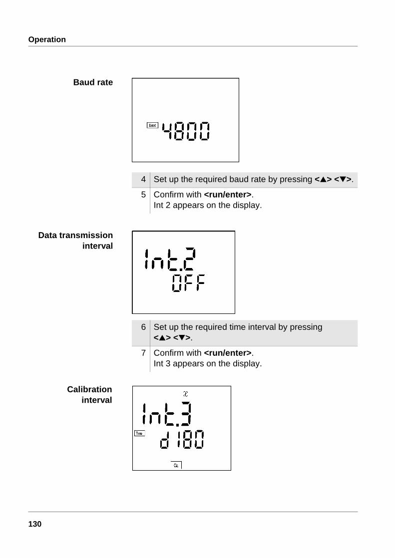
4 Set up the required baud rate by pressing <> <>.
5 Confirm with <run/enter>.Int 2 appears on the display.
6 Set up the required time interval by pressing <> <>.
7 Confirm with <run/enter>. Int 3 appears on the display.
Baud rate
Data transmissioninterval
Calibrationinterval
130

Operation
8 Set up the required time interval by pressing <> <>.
9 Confirm with <run/enter>. ARng appears on the display.
10 With <> <> select between YES and no.
11 Confirm with <run/enter>. t25 appears on the dis-play.
12 With <> <> select between t25 and t20 .
13 Confirm with <run/enter>. LF appears on the display.
ARng (AutoRange)
Referencetemperature
131
Operation
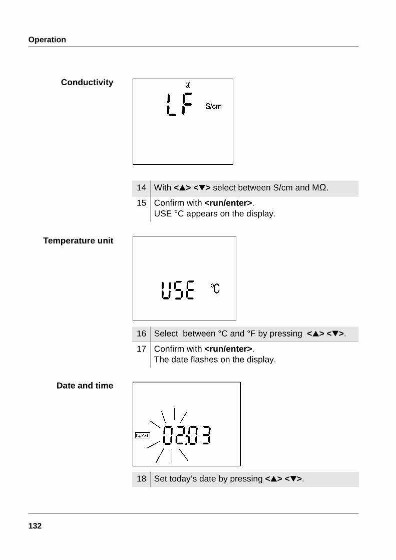
14 With <> <> select between S/cm and MΩ.
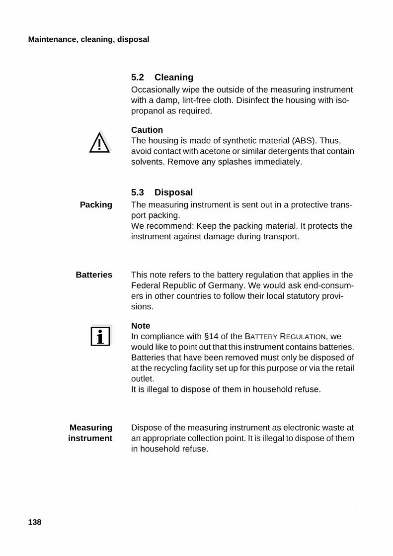
15 Confirm with <run/enter>.USE °C appears on the display.
16 Select between °C and °F by pressing <> <>.
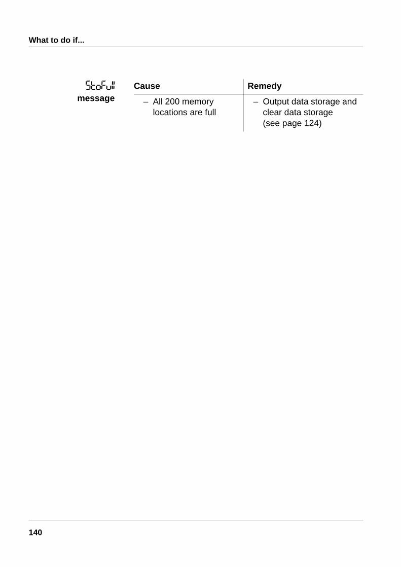
17 Confirm with <run/enter>.The date flashes on the display.
18 Set today’s date by pressing <> <>.
Conductivity
Temperature unit
Date and time
132

Operation
19 Confirm with <run/enter>.The date (month) flashes on the display.
20 Set the current month by pressing <> <>.
21 Confirm with <run/enter>.The year appears on the display.
22 Set the current year by pressing <> <>.
23 Confirm with <run/enter>.The hours flash on the display.
24 Set the current time by pressing <> <>.
25 Confirm with <run/enter>.The minutes flash on the display.
26 Set the current time by pressing <> <>.
27 Confirm with <run/enter>.The instrument changes automatically to the conduc-tivity measuring mode.
133

Operation
4.7 ResetYou can reset (initialize) measuring and configuration parameters separately from one another.
Measuringparameters
The following measuring parameters (Cond InI) are reset to the values they had on delivery:
NoteWhen the measuring parameters are reset, the calibration data are lost. After the parameters have been reset, cali-brate!
Configurationparameters
The following configuration parameters (InI) are reset to the values they had on delivery:
Measuring mode
Cell constant 0.475 cm-1 (calibrated)0.475 cm-1 (set up)
Temperature compensation
nLF
Reference temperature
Temperature coefficient of the linear temperature compensation
2.000 %/K
TDS factor 1.00
Baud rate 4800
Interval 1(automatic storing) OFF
Interval 2(for data transmission) OFF
134

Operation
1 Press and hold down the <run/enter> key.
2 Press the <CAL> key.
3 Use <> <> to toggle between no and yes.yes: reset measuring parameters.no: retain settings.
4 Confirm with <run/enter>.The instrument changes to the configuration parameters.
5 Toggle between no and yes by pressing <> <>.yes: reset configuration parameters.no: retain settings.
6 Confirm with <run/enter>.The instrument changes automatically to the conduc-tivity measuring mode.
Resettingmeasuring
parameters
Resettingconfiguration
parameters
135

Operation
136

Maintenance, cleaning, disposal
5 Maintenance, cleaning, disposal
5.1 MaintenanceThe measuring instrument is almost maintenance-free. The only maintenance task is replacing the batteries.
NoteSee the relevant operating manual of the electrode for in-structions on maintenance.
CautionMake sure that the poles of the batteries are the right way round. The ± signs in the battery compartment must corre-spond to the ± signs on the batteries. Only use leakproof alkaline manganese batteries.
1 Open the battery compartment (1) on the underside of the instrument.
2 Remove the four batteries from the battery compart-ment.
3 Insert four new batteries (Type Mignon AA) into the battery compartment.
4 Close the battery compartment (1).The date (day) flashes on the display.
5 Set up the date and time according to chapter 3 COM-MISSIONING.
1
137
Maintenance, cleaning, disposal
5.2 CleaningOccasionally wipe the outside of the measuring instrument with a damp, lint-free cloth. Disinfect the housing with iso-propanol as required.
CautionThe housing is made of synthetic material (ABS). Thus, avoid contact with acetone or similar detergents that contain solvents. Remove any splashes immediately.
5.3 DisposalPacking The measuring instrument is sent out in a protective trans-
port packing. We recommend: Keep the packing material. It protects the instrument against damage during transport.
Batteries This note refers to the battery regulation that applies in the Federal Republic of Germany. We would ask end-consum-ers in other countries to follow their local statutory provi-sions.
NoteIn compliance with §14 of the BATTERY REGULATION, we would like to point out that this instrument contains batteries. Batteries that have been removed must only be disposed of at the recycling facility set up for this purpose or via the retail outlet. It is illegal to dispose of them in household refuse.
Measuringinstrument
Dispose of the measuring instrument as electronic waste at an appropriate collection point. It is illegal to dispose of them in household refuse.
138

What to do if...
6 What to do if...
Cause Remedy
– Measuring cell not connected
– Connect measuring cell
– Cable broken – Replace electrode
Cause Remedy
– Measuring cell contaminated
– Clean measuring cell; if necessary, replace it
– Unsuitable calibration solution
– Check calibration solutions
Cause Remedy
– Batteries almost depleted
– Replace batteries(see section 5.1 MAINTENANCE)
Cause Remedy
– Operating state undefined or EMC electric stress unallowed
– Processor reset:Press the <auto read> key and switch on instrument
Cause Remedy
– Timeout of the interface – Check connected instrument
Error message,I/
Error message,
LoBat
Instrument does notreact to keystroke
*(display
139
What to do if...
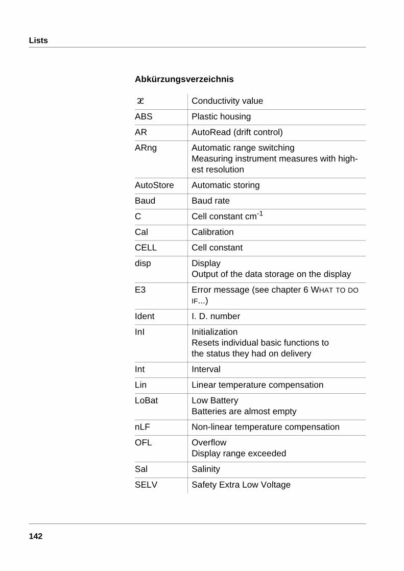
Cause Remedy
– All 200 memory locations are full
– Output data storage and clear data storage(see page 124)
*(+,,message
140

Lists
7 Lists
This chapter provides additional information and orientation aids.
Abbreviations The list of abbreviations explains abbreviations that appear on the display or when dealing with the instrument.
Specialist terms The glossary briefly explains the meaning of the specialist terms. However, terms that should already be familiar to the target group are not described here.
Index The index helps you find the topics that you are looking for.
141
Lists
Abkürzungsverzeichnis
Conductivity value
ABS Plastic housing
AR AutoRead (drift control)
ARng Automatic range switchingMeasuring instrument measures with high-est resolution
AutoStore Automatic storing
Baud Baud rate
C Cell constant cm-1
Cal Calibration
CELL Cell constant
disp DisplayOutput of the data storage on the display
E3 Error message (see chapter 6 WHAT TO DO IF...)
Ident I. D. number
InI InitializationResets individual basic functions to the status they had on delivery
Int Interval
Lin Linear temperature compensation
LoBat Low BatteryBatteries are almost empty
nLF Non-linear temperature compensation
OFL OverflowDisplay range exceeded
Sal Salinity
SELV Safety Extra Low Voltage
142
Lists
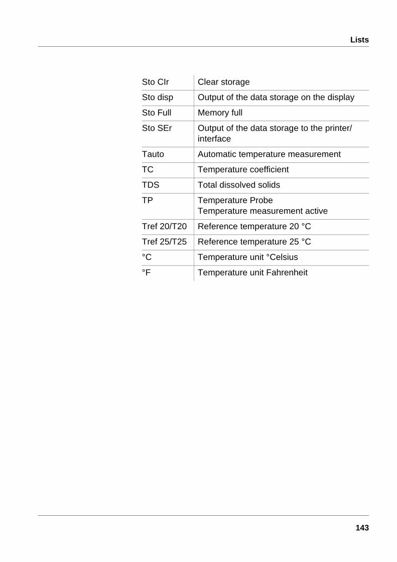
Sto CIr Clear storage
Sto disp Output of the data storage on the display
Sto Full Memory full
Sto SEr Output of the data storage to the printer/interface
Tauto Automatic temperature measurement
TC Temperature coefficient
TDS Total dissolved solids
TP Temperature ProbeTemperature measurement active
Tref 20/T20 Reference temperature 20 °C
Tref 25/T25 Reference temperature 25 °C
°C Temperature unit °Celsius
°F Temperature unit Fahrenheit
143
Lists
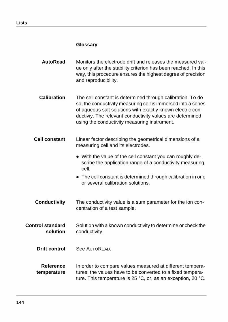
Glossary
AutoRead Monitors the electrode drift and releases the measured val-ue only after the stability criterion has been reached. In this way, this procedure ensures the highest degree of precision and reproducibility.
Calibration The cell constant is determined through calibration. To do so, the conductivity measuring cell is immersed into a series of aqueous salt solutions with exactly known electric con-ductiviy. The relevant conductivity values are determined using the conductivity measuring instrument.
Cell constant Linear factor describing the geometrical dimensions of a measuring cell and its electrodes.
l With the value of the cell constant you can roughly de-scribe the application range of a conductivity measuring cell.
l The cell constant is determined through calibration in one or several calibration solutions.
Conductivity The conductivity value is a sum parameter for the ion con-centration of a test sample.
Control standardsolution
Solution with a known conductivity to determine or check the conductivity.
Drift control See AUTOREAD.
Referencetemperature
In order to compare values measured at different tempera-tures, the values have to be converted to a fixed tempera-ture. This temperature is 25 °C, or, as an exception, 20 °C.
144

Lists
Resistance All substances (solids, liquids, or gases) with mobile charge carriers like for example electrons or ions have a finite ohmic resistance, which means they have an electric conductance that can be measured or an electric conducitivtiy.
Salinity The salinity is a sum parameter especially for seawater;it gives the salt content of seawater.
Temperaturecompensation (TC)
The temperature has a very strong impact on the electrical conductivity. To be able to compare measured values, it is necessary to temper or convert the test sample to a refer-ence temperature.
Test sample The substance to be measured. It can be liquid or solid.
Total dissolvedsolids (TDS)
Mass that remains of the substances dissolved in an aque-ous solution after a fixed filtering and drying procedure, as far as these substances are not volatile under the conditions of this procedure. The total dissolved solids refer to the vol-ume of the filtered aqueous sample used und are given in mg/l.
145

Lists
146

Lists
Index
Aanalog output 127authorized use 90AutoRange 131AutoRead 98AutoStore 116
Bbatteries, replacing 137battery compartment 137baud rate, setting 130
Ccalibration 103
interval 106protocol 105
calibration evaluation 105cell constant 96, 103cleaning 138commissioning 93condition on delivery 134conductivity 132conductivity measurement 99conductivity/resistance 127
Ddata record 114data transmission (interval) 126date, setting 132display 81disposal 138drift control 98
Eenergy saving feature 95error messages 139
Iinitialize 134interval
calibration (Int 3) 106storing (Int 1) 116
Kkeys 80
Llinear temperature compensation 110, 112LoBat 139
Mmaintenance 137manual storing 114measuring 97measuring precision 106
Nno temperature compensation 110non-linear temperature compensation 110, 111
Ooperation 95operational safety 90output data storage 118
Pplace of the instrument 95plug-in power supply 94power supply 94printing
calibration protocol 105measured values 102
147

Lists
Rrecorder output 127reference temperature 131replacing the batteries 137reset 134RS232 interface 128
Ssafety 89safety precautions 89salinity 127salinity measurement 100sockets 81storing 114
TTDS 127TDS (total dissolved solids) 101temperature compensation 110
linear 112non-linear 111setting 110switch off 113
temperature probe 97temperature unit 132time
setting 93time, setting 132total dissolved solids measurement 101transmit data 125transmitting measured values 102
WWhat to do if... 139
148