Condition Code Register (CCR)ece.eng.umanitoba.ca/undergraduate/ECE3610/LectureNotes...4-BIT SIGNED...
38
1 Condition Code Register (CCR)
Transcript of Condition Code Register (CCR)ece.eng.umanitoba.ca/undergraduate/ECE3610/LectureNotes...4-BIT SIGNED...

1
Condition Code Register (CCR)

2
• The purpose of the CCR is to retain the characteristics of the last ALU operation.
• For example– Did the last ALU operation produce a most significant carry/borrow?– Did the last ALU operation produce a zero result?– Did the last ALU operation produce a negative or positive result?
• CCR is important, when writing assembly language programs:– Need to know for division (by zero)– Need to know if one number is equal/greater/bigger/less
than/smaller/same to another number.– Need to know for other general processing tasks.

3
CONDITION CODE REGISTERCCR AND LOGIC CIRCUIT CONNECTION TO ALU
07CarryoVerflowZeroNegativeInterruptHalf-carryX interrupt maskStop disable
Condition Code Register (CCR)
A Inputs
8
B Inputs
Output
8
R7 R6 R5 R4 R3 R2 R1 R0
ALU
CombinationalLogicCircuit
Cout
RBUS
Cout
R7
CVZNHS X I
CCR
ZD
CLK
QZ
ND
CLK
QN
VD
CLK
QV
CD
CLK
QC

4
The Carry Flag in the CCR indicates the state of the carry
or borrow that was produced in the last ALU operation that
affected the Carry Flag.

5
• Recall the meaning of the most significant carry in the addition of two n-bit operands.
• Recall the meaning of the most significant borrow in the subtraction of two n-bit operands.
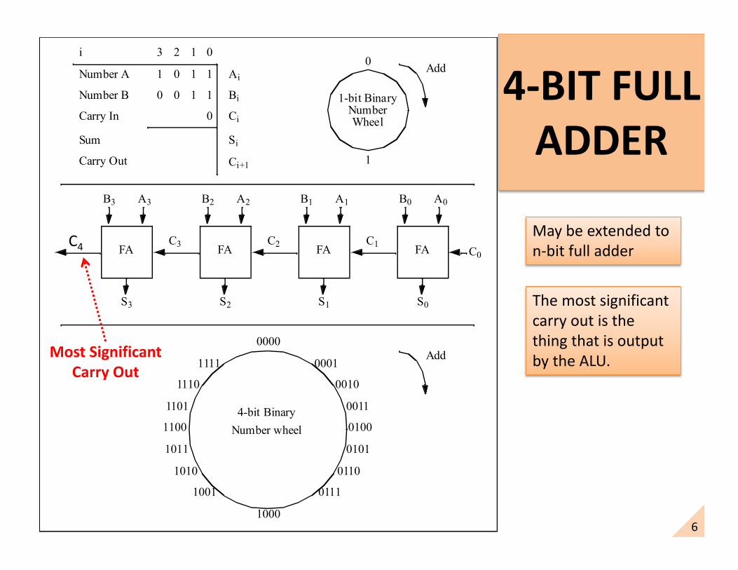
6
4-BIT FULL ADDER
1 0 1 1Number A
Number B
Carry In
0
1
1-bit BinaryNumberWheel
Sum
Carry Out
FA
Add
Ci
Ai
Bi
Si
Ci+1
0 0 1 1
0
3 2 1 0i
B0 A0
C0
S0
C1FA
B1 A1
S1
C2FA
B2 A2
S2
C3FA
B3 A3
S3
C4
0000
1000
0001
0010
0011
0100
0101
0110
0111
1111
1110
1101
1100
1011
1010
1001
4-bit BinaryNumber wheel
Add
C4
Most SignificantCarry Out
May be extended to n-bit full adder
The most significant carry out is the thing that is output by the ALU.

7
4-BIT FULL SUBTRACTOR
1 0 1 1Number A
Number B
Carry In
0
1
1-bit BinaryNumberWheel
Sum
Carry Out
FA
Add
Ci
Ai
Bi
Si
Ci+1
0 0 1 1
0
3 2 1 0i
B0 A0
C0
S0
C1FA
B1 A1
S1
C2FA
B2 A2
S2
C3FA
B3 A3
S3
C4
0000
1000
0001
0010
0011
0100
0101
0110
0111
1111
1110
1101
1100
1011
1010
1001
4-bit BinaryNumber wheel
Add
B0B1B2B3B4
SUB
SUB
Borrow In
Borrow Out
Most SignificantBorrow Out
May be extended to n-bit full adder
The most significant borrow out is the thing that is output by the ALU.
8
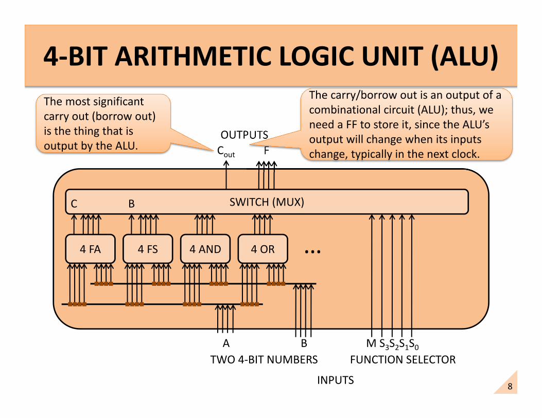
4-BIT ARITHMETIC LOGIC UNIT (ALU)
4 FA 4 FS 4 AND 4 OR …
SWITCH (MUX)
A B
F
M S3S2S1S0
FUNCTION SELECTOR
INPUTS
OUTPUTS
C B
Cout
TWO 4-BIT NUMBERS
The most significant carry out (borrow out) is the thing that is output by the ALU.
The carry/borrow out is an output of a combinational circuit (ALU); thus, we need a FF to store it, since the ALU’soutput will change when its inputs change, typically in the next clock.
9
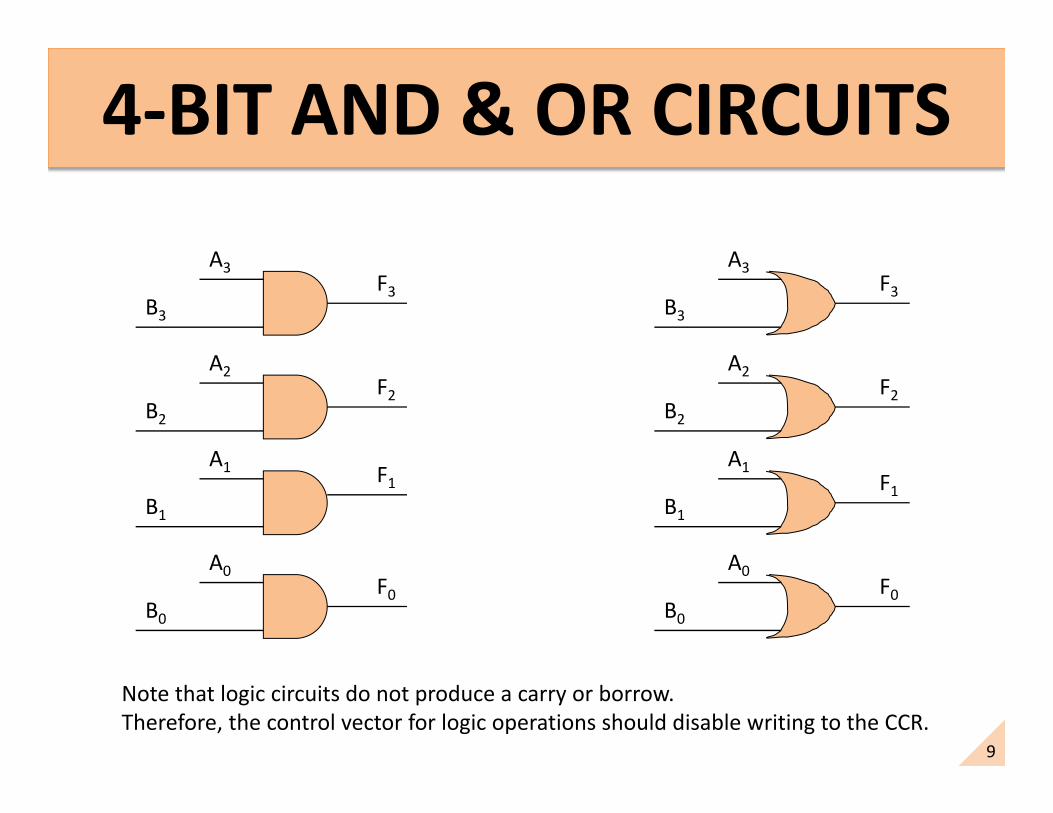
A3
B3
A2
B2
A1
B1
A0
B0
F3
F2
F1
F0
A3
B3
A2
B2
A1
B1
A0
B0
F3
F2
F1
F0
Note that logic circuits do not produce a carry or borrow.Therefore, the control vector for logic operations should disable writing to the CCR.

10
ALU FUNCTION TABLEEXAMPLE 4-BIT
S3 S2 S1 S0 LOGIC(M=1)
ARITHMETIC(M=0)
0 0 0 0 A’ A
0 0 0 1 B’ B
0 0 1 0 A AND B A PLUS B
0 0 1 1 A OR B A MINUS B
0 1 0 0 A NAND B A + 1
0 1 0 1 A A - 1
0 1 1 0 B B + 1
0 1 1 1 A XOR B B - 1
Only arithmetic operations should cause the Carry FF to write.
11
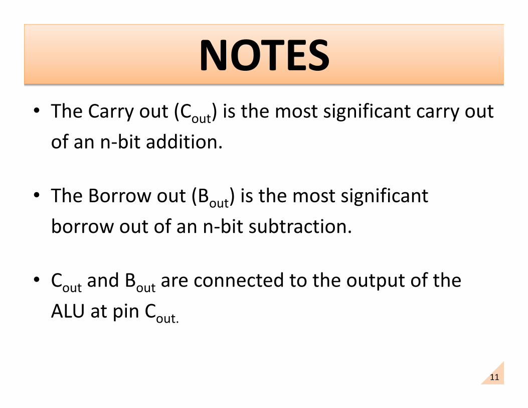
• The Carry out (Cout) is the most significant carry out of an n-bit addition.
• The Borrow out (Bout) is the most significant borrow out of an n-bit subtraction.
• Cout and Bout are connected to the output of the ALU at pin Cout.

12
• Cout and Bout do not make sense for logical operations.
• In the case the ALU performs a logic operation, the state of the Cout
pin of the ALU will not be known, because a logic operation does not generate Cout.
• The carry flag (i.e., carry flip flop) of the CCR should be updated ONLY when the ALU is performing an arithmetic operation, (i.e., either an addition or a subtraction).
• The instruction set designer determines when the carry flag of the CCR should be updated by creating a Carry FF enable signal in the control vector for a micro-operation of an instruction.

13
• If EC = TRUE, then:• If the last ALU result produced a MS
carry=1, then QC = 1, when φ2 negedge.• Otherwise, if the last ALU result produced
MS carry=0, then QC = 0 , when φ2 negedge.
• Where does EC come from?• It is a component of the control vector, and
its state must be specified by the designers for every instruction in the instruction set.
CCR
φ2EC
ZD
CLK
QZ
ND
CLK
QN
VD
CLK
QV
CD
CLK
QC
COUT
n-bit Full Adder/Subtractor Most
Significant (MS) carry out or borrow out: i.e., Cout of
ALU.
φ2
14
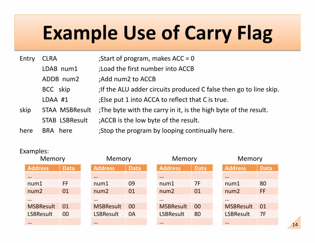
Example Use of Carry FlagEntry CLRA ;Start of program, makes ACC = 0
LDAB num1 ;Load the first number into ACCBADDB num2 ;Add num2 to ACCBBCC skip ;If the ALU adder circuits produced C false then go to line skip.LDAA #1 ;Else put 1 into ACCA to reflect that C is true.
skip STAA MSBResult ;The byte with the carry in it, is the high byte of the result.STAB LSBResult ;ACCB is the low byte of the result.
here BRA here ;Stop the program by looping continually here.
Examples:Memory
Address Data…num1 FFnum2 01…MSBResult 01LSBResult 00…
MemoryAddress Data…num1 09num2 01…MSBResult 00LSBResult 0A…
MemoryAddress Data…num1 7Fnum2 01…MSBResult 00LSBResult 80…
MemoryAddress Data…num1 80num2 FF…MSBResult 01LSBResult 7F…
15
The Zero Flag in the CCR indicates whether the last ALU operation produced a
zero or not a zero.

16
R7R6R5R4R3R2R1R0
• If EZ = TRUE, then:• If the last ALU result produced an 8-bit zero,
then QZ = 1, when φ2 negedge.• Otherwise, if at least one bit of the last ALU
result is 1, then QZ = 0 , when φ2 negedge.
Last
ALU
Res
ult
CCR
ZD
CLK
ND
CLK
VD
CLK
CD
CLK
QZ
QN
QV
QC
EZ: Is a Control vector component.
φ2EZ

17
• The Z-flag makes sense for arithmetic and logical operations.
• But, the Z-flag may not make sense for other operations, such as branch and jump (discussed later).
• The zero flag (i.e., zero flip flop) of the CCR should be updated ONLY when the ALU is performing arithmetic and logic operations.
• The instruction set designer determines when the zero flag of the CCR should be updated by creating a Zero FF enable signal in the control vector.
18
WHAT IS THE OVERFLOW FLAG?
The Overflow Flag in the CCR indicates the state of
the overflow that was produced in the last ALU
operation.

19
• Let’s look at an example signed number system.
• 4-bit signed number system.
• Analyze addition and subtraction.
• Show what overflow is and how it can be detected.
20
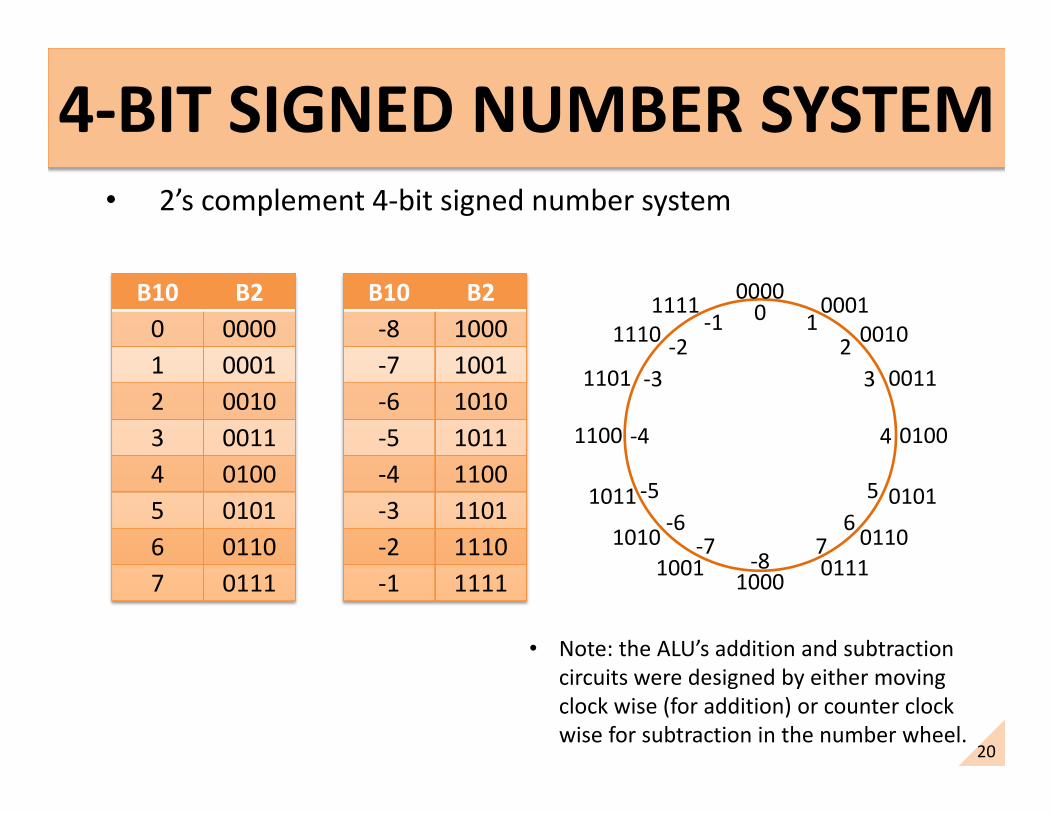
4-BIT SIGNED NUMBER SYSTEM • 2’s complement 4-bit signed number system
B10 B20 00001 00012 00103 00114 01005 01016 01107 0111
B10 B2-8 1000-7 1001-6 1010-5 1011-4 1100-3 1101-2 1110-1 1111
0000
0010
0011
0100
0101
0110
0001
0111100010011010
1011
1100
1101
11101111 0
-8
12
3
4
56
7-7-6
-5
-4
-3-2
-1
• Note: the ALU’s addition and subtraction circuits were designed by either moving clock wise (for addition) or counter clock wise for subtraction in the number wheel.

21
• Consider addition/subtraction of numbers with the same sign
– Will show that the answer given by the ALU is correct, while in other cases, the answer is incorrect, due to the overflow problem.
– Therefore, we need another indicator called oVerflow to tell the programmers (i.e., us) when the ALU arithmetic circuits experienced an overflow.
• Consider addition/subtraction of numbers with opposite sign
– Will show that for all cases, the answer given by the circuit in the ALU is correct.
– Therefore, for these cases, the overflow condition is always false.

22
2’s COMPLEMENT NUMBER SYSTEMEXCEEDING THE CAPACITY (OVERFLOW)
• When adding (or subtracting) binary numbers, the signed capacity of the 2’s complement number system may be exceeded. This is called overflow.
• Example: 7 + 1 = 0111 + 0001 = 1000 (negative result? Can’t be!)• Example: -8 + -1 = 1000 + 1111 = 0111 (positive result? Can’t be!)
0000
0010
0011
0100
0101
0110
0001
0111100010011010
1011
1100
1101
11101111 0
-8
12
3
4
56
7-7-6
-5
-4
-3-2
-1
23
ADDITION COMBINATIONS THAT DO NOT OVERFLOW THE SYSTEM
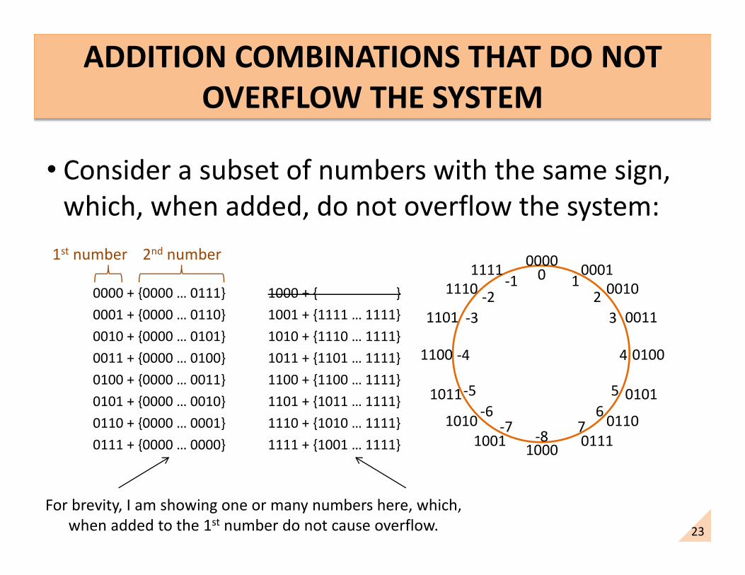
• Consider a subset of numbers with the same sign, which, when added, do not overflow the system:
0000 + {0000 … 0111}0001 + {0000 … 0110}0010 + {0000 … 0101}0011 + {0000 … 0100}0100 + {0000 … 0011}0101 + {0000 … 0010}0110 + {0000 … 0001}0111 + {0000 … 0000}
1000 + { }1001 + {1111 … 1111}1010 + {1110 … 1111}1011 + {1101 … 1111}1100 + {1100 … 1111}1101 + {1011 … 1111}1110 + {1010 … 1111}1111 + {1001 … 1111}
0000
0010
0011
0100
0101
0110
0001
0111100010011010
1011
1100
1101
11101111 0
-8
12
3
4
56
7-7-6
-5
-4
-3-2
-1
1st number 2nd number
For brevity, I am showing one or many numbers here, which, when added to the 1st number do not cause overflow.
24
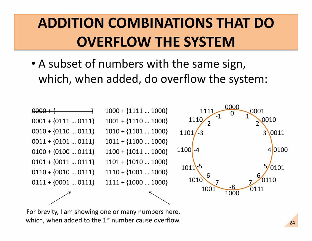
ADDITION COMBINATIONS THAT DO OVERFLOW THE SYSTEM
• A subset of numbers with the same sign, which, when added, do overflow the system:
0000 + { }0001 + {0111 … 0111}0010 + {0110 … 0111}0011 + {0101 … 0111}0100 + {0100 … 0111}0101 + {0011 … 0111}0110 + {0010 … 0111}0111 + {0001 … 0111}
1000 + {1111 … 1000}1001 + {1110 … 1000}1010 + {1101 … 1000}1011 + {1100 … 1000}1100 + {1011 … 1000}1101 + {1010 … 1000}1110 + {1001 … 1000}1111 + {1000 … 1000}
0000
0010
0011
0100
0101
0110
0001
0111100010011010
1011
1100
1101
11101111 0
-8
12
3
4
56
7-7-6
-5
-4
-3-2
-1
For brevity, I am showing one or many numbers here, which, when added to the 1st number cause overflow.

25
ADDITION COMBINATIONS THAT WILL NEVER OVERFLOW THE SYSTEM
• Adding numbers of opposite sign will never overflow the system:
0000 + {1000 … 1111}0001 + {1000 … 1111}0010 + {1000 … 1111}0011 + {1000 … 1111}0100 + {1000 … 1111}0101 + {1000 … 1111}0110 + {1000 … 1111}0111 + {1000 … 1111}
1000 + {0000 … 0111}1001 + {0000 … 0111}1010 + {0000 … 0111}1011 + {0000 … 0111}1100 + {0000 … 0111}1101 + {0000 … 0111}1110 + {0000 … 0111}1111 + {0000 … 0111}
0000
0010
0011
0100
0101
0110
0001
0111100010011010
1011
1100
1101
11101111 0
-8
12
3
4
56
7-7-6
-5
-4
-3-2
-1
• This tested all possible combinations of adding two 4-bit numbers of opposite sign, and none of them caused an overflow.
• Note: Without loss of generality, the addition of two n-bit numbers of the same sign will never overflow the number system.

26
• The addition of some numbers of the same sign in the ALU full adder circuit do not cause overflow.
• The addition of some numbers of the same sign in the ALU full adder circuit cause overflow.
• Some additions cause overflow, while some additions do not cause overflow.
• The addition of numbers of opposite sign do not cause overflow.
• The signed number handling capacity of the adder circuits in the ALU will not be exceeded when adding numbers of the same sign.

27
• Let V represent (or indicate) the state of the oVerflow of the ALUarithmetic circuits.– Let V=1 (true) mean that overflow had occurred.– Let V=0 (false) mean that overflow had not occurred.
• Definition and detection of overflow (for addition)
– If two numbers of the same sign are added in the ALU adder circuit, and the result has an opposite sign, then overflow has occurred; Our indicator should be set to V=TRUE.
– If two numbers of the same sign are added in the ALU adder circuit, and the result has the same sign, then overflow has not occurred; Our indicator should be set to V=FALSE.
– If two numbers of opposite sign are added, then overflow V=FALSE, because our analysis found that adding numbers of opposite sign always does not cause an overflow problem.

28
ADDITION OVERFLOW DETECTOR CIRCUIT(R = A + B)
• The overflow indicator should be set to V=TRUE when two numbers of the same sign are added and the result has an opposite sign.
• Example: design an addition overflow detector for a 4-bit system
– For addition, overflow is TRUE whenever two positive numbers are added, and the result is negative, OR, whenever two negative numbers are added, and the result is positive.
– Note: When two numbers of opposite sign are added, the circuits output V=0, as desired.
A3B3R3
A3B3R3
V
Recall: MSb indicates the sign of the number.0: positive1: negative
29
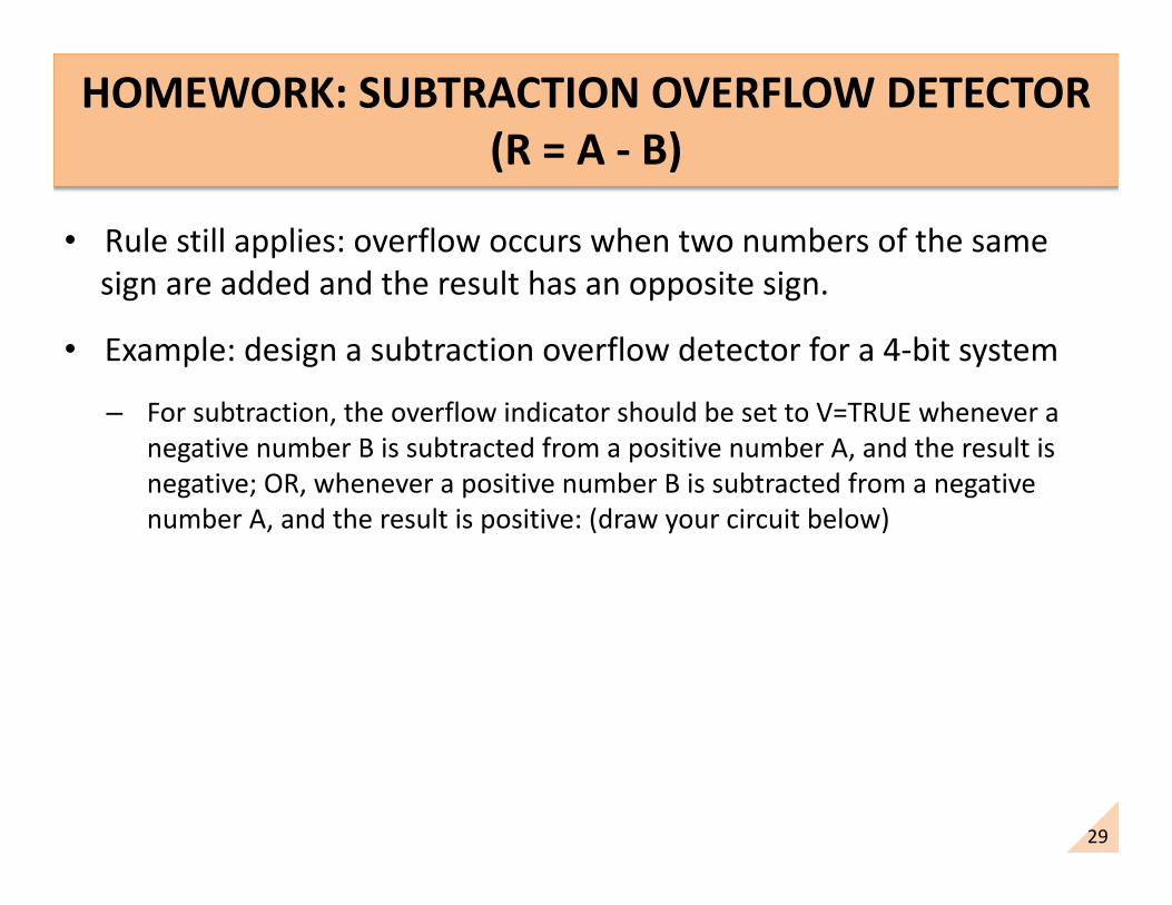
HOMEWORK: SUBTRACTION OVERFLOW DETECTOR (R = A - B)
• Rule still applies: overflow occurs when two numbers of the same sign are added and the result has an opposite sign.
• Example: design a subtraction overflow detector for a 4-bit system
– For subtraction, the overflow indicator should be set to V=TRUE whenever a negative number B is subtracted from a positive number A, and the result is negative; OR, whenever a positive number B is subtracted from a negative number A, and the result is positive: (draw your circuit below)

30
HOMEWORK: SUBTRACTION OVERFLOW DETECTOR (R = A - B)
V = A3B3R3 + A3B3R3

31
“Overflow is NOT defined for unsigned numbers, and we ignore the overflow indicator when
performing arithmetic with unsigned numbers.”
IRRELEVANCE TO UNSIGNED NUMBER SYSTEM
• Note: Overflow has no meaning for unsigned numbers, because unsigned numbers do not have a sign, and the definition of overflow specifies the sign of a number.
• For example, if we are adding 7 + 1 (0111 + 0001), the ALU output would be 1000, which, when interpreted as an unsigned number, is interpreted as 8 (1000), the correct result.
– Our overflow indicator in the CCR would be set to V=TRUE, but, as programmers, we ignore the overflow indicator when adding unsigned numbers.
32
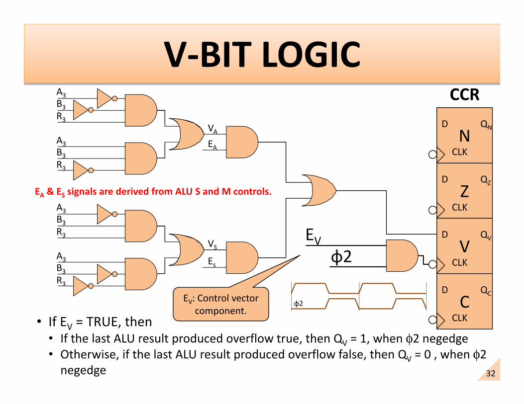
• If EV = TRUE, then• If the last ALU result produced overflow true, then QV = 1, when φ2 negedge• Otherwise, if the last ALU result produced overflow false, then QV = 0 , when φ2
negedge
CCR
EV
ZD
CLK
QZ
ND
CLK
QN
VD
CLK
QV
CD
CLK
QC
VS
A3B3R3
A3B3R3
VA
A3B3R3
A3B3R3
EA
Es
EA & ES signals are derived from ALU S and M controls.
EV: Control vector component.
φ2
φ2
33
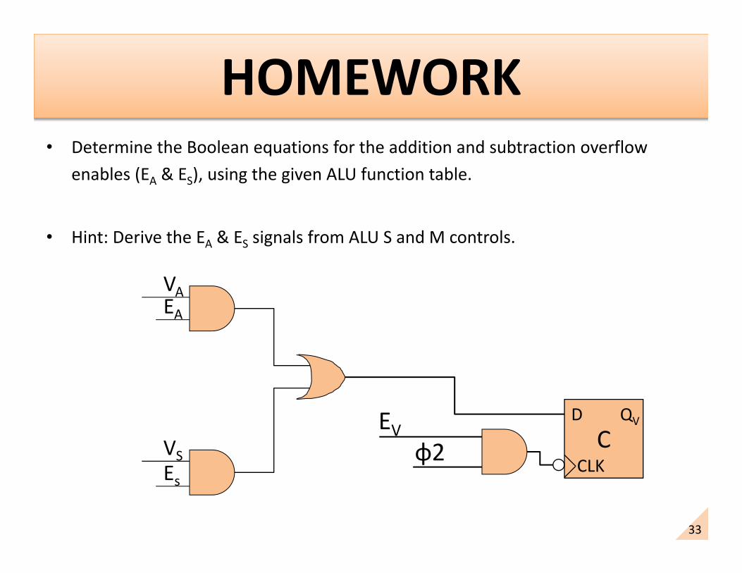
• Determine the Boolean equations for the addition and subtraction overflow enables (EA & ES), using the given ALU function table.
• Hint: Derive the EA & ES signals from ALU S and M controls.
CD
CLK
QV
VS
VAEA
Es
EVφ2
34
WHAT IS THE NEGATIVE FLAG ?
• The Negative Flag in the CCR indicates whether the last ALU operation produced a result with MSb = 1 (which we would interpret as a negative result), or MSb=0 (which we would interpret as a positive result).

35
• If EN = TRUE, then
• If the last ALU result produced negative result, then QN = 1, when φ2 negedge.
• Otherwise, if the last ALU result produced positive result, then QN= 0 , when φ2 negedge.
CCR
ZD
CLK
QZ
ND
CLK
QN
VD
CLK
QV
CD
CLK
QC
R7Most
significant bit of ALU result
EN : Control vector component.
ENφ2
36
• Instructions affect the CCR bits in different ways. For example:– A logic instruction would not affect the V-bit– An arithmetic instruction would affect all bits {NZVC}– A Load/store instruction would only affect the {NZ} bits
• The enable signals {EN EZ EV EC} are components of the control vector of an instruction that control which bits of the CCR will be affected by the instruction.
• The instruction set designer determines which enable signal should be true and which should be false for a given instruction.
• If an enable signal {EN EZ EV EC} is true, the respective bit in the CCR is written with a state that depends on the instruction.
• If an enable signal {EN EZ EV EC} is false, the respective bit in the CCR is not written (φ2would be blocked) and the CCR bit retains its value.

37
CARRY/OVERFLOW SUMMARY• For unsigned arithmetic, the C-bit is important and V-bit is ignored.
For example:255 + 1 = 0b1111 1111 + 0b0000 0001 = 0b0000 0000 with C = 1 and V = 0.The result should be written as = 0b0000 000C 0000 0000
= 0b0000 0001 0000 0000 = 0x0100
Another example:127 + 1 = 0b0111 1111 + 0b0000 0001 = 0b1000 0000 with C = 0 and V = 1.THe result should be written as = 0b0000 000C 1000 0000
= 0b0000 0000 1000 0000 = 0x0080

38
CARRY/OVERFLOW SUMMARY• For signed arithmetic, the V-bit is important and C-bit is ignored.
– We determined that the C-bit should be ignored by considering all possible addition and subtraction combinations of 4-bit numbers, and found that the C-bit was not needed, and we found cases where we needed to ignore the C-bit.
For example:-1 + 1 = 0b1111 1111 + 0b0000 0001 = 0b0000 0000 with C = 1 and V = 0.Our result should be written as = 0b0000 0000 0000 0000 = 0x0000– By considering all possible addition and subtraction combinations of 4-bit signed
numbers, we found that the V-bit was needed to let us know if the circuits had undergone an overflow.
For example:+127 + 1 = 0b0111 1111 + 0b0000 0001 = 0b1000 0000 with C = 0 and V = 1.The result cannot be written as = 0b1000 0000
= -128