Condition Assessment of William Beaumont General … Approved for public release; distribution is...
170
Approved for public release; distribution is unlimited. ERDC/CERL TR-02-26 Condition Assessment of William Beaumont General Hospital Historic Buildings at Fort Bliss, Texas Construction Engineering Research Laboratory Thomas R. Napier and Sheila A. McCarthy September 2002 us Army Corps of Engineers® Engineer Research and Development Center
Transcript of Condition Assessment of William Beaumont General … Approved for public release; distribution is...

Approved for public release; distribution is unlimited.
ERD
C/C
ERL
TR-0
2-26
Condition Assessment of William Beaumont General Hospital Historic Buildings at Fort Bliss, Texas
Con
stru
ctio
n E
ngin
eeri
ng
Res
earc
h La
bora
tory
Thomas R. Napier and Sheila A. McCarthy September 2002
us Army Corps of Engineers® Engineer Research and Development Center

2 ERDC/CERL TR-02-26
Foreword This study was conducted for the Department of Environment, Fort Bliss, TX, under Military Interdepartmental Purchase Request (MIPR) 2042-96, “William Beaumont Army Medical Center Mitigation,” dated 30 September 1996. The technical monitor was Daniel Delahaye, ATZC-DOE-C.
The work was performed by the Facilities Maintenance Branch (CF-F) of the Facili-ties Division (CF), Construction Engineering Research Laboratory (CERL). The CERL Principal Investigator was Thomas R. Napier. The technical editor was Gordon L. Cohen, Information Technology Laboratory – Champaign. Mark W. Slaughter is Chief, CEERD-CF-F, and L. Michael Golish is Chief, CEERD-CF. The Technical Director of the Facility Acquisition and Revitalization business area is Dr. Paul A. Howdyshell, CEERD-CV-ZT, and the Director of CERL is Dr. Alan W. Moore.
CERL is an element of the Engineer Research and Development Center (ERDC), U.S. Army Corps of Engineers. The Commander and Executive Director of ERDC is COL John W. Morris III, EN, and the Director is Dr. James R. Houston.
DISCLAIMER: The contents of this report are not to be used for advertising, publication, or promotional purposes. Citation of trade names does not constitute an official endorsement or approval of the use of such commercial products. All product names and trademarks cited are the property of their respective owners. The findings of this report are not to be construed as an official Department of the Army position unless so designated by other authorized documents. DESTROY THIS REPORT WHEN IT IS NO LONGER NEEDED. DO NOT RETURN IT TO THE ORIGINATOR.

ERDC/CERL TR-02-26 3
Contents Foreword ............................................................................................................................................2
List of Illustrations ............................................................................................................................6
1 Introduction.................................................................................................................................9 1.1 Background...................................................................................................................9 1.2 Objective.....................................................................................................................10 1.3 Research Methodology...............................................................................................10 1.4 Organization of Report ............................................................................................... 11 1.5 Units of Weight and Measure .....................................................................................13
2 Building 7122: Bandstand......................................................................................................14 2.1 Description..................................................................................................................14 2.2 Condition Assessment ................................................................................................15
2.2.1 Foundation and Slab ....................................................................................................15 2.2.2 Columns and Rail .........................................................................................................17 2.2.3 Roof..............................................................................................................................18
2.3 Recommendations......................................................................................................19
3 Building 7151: Chapel.............................................................................................................20 3.1 Description..................................................................................................................20 3.2 Condition Assessment ................................................................................................22
3.2.1 Substructure .................................................................................................................22 3.2.2 Superstructure..............................................................................................................23 3.2.3 Floor Construction ........................................................................................................23 3.2.4 Roof Construction.........................................................................................................24
3.3 Exterior Closure..........................................................................................................24 3.3.1 Walls.............................................................................................................................24 3.3.2 Windows and Doors .....................................................................................................25 3.3.3 Roofing .........................................................................................................................27
3.4 Interior Construction ...................................................................................................28 3.4.1 Partition Construction ...................................................................................................29 3.4.2 Finishes ........................................................................................................................31 3.4.3 Other Interior Construction ...........................................................................................32
3.5 Services ......................................................................................................................33 3.5.1 Plumbing ......................................................................................................................33 3.5.2 Heating, Ventilating, and Air Conditioning (HVAC) .......................................................34 3.5.3 Electrical.......................................................................................................................34
3.6 Sitework ......................................................................................................................34 3.7 Recommendations......................................................................................................35
4 Building 7152: Theater............................................................................................................38

4 ERDC/CERL TR-02-26
4.1 Description..................................................................................................................38 4.2 Condition Assessment ................................................................................................40
4.2.1 Substructure .................................................................................................................40 4.2.2 Superstructure..............................................................................................................40 4.2.3 Floor Construction ........................................................................................................40 4.2.4 Roof Construction.........................................................................................................41
4.3 Exterior Closure..........................................................................................................41 4.3.1 Walls.............................................................................................................................41 4.3.2 Windows and Doors .....................................................................................................42 4.3.3 Roofing .........................................................................................................................42
4.4 Interior Construction ...................................................................................................43 4.5 Services ......................................................................................................................45 4.6 Sitework ......................................................................................................................45 4.7 Recommendations......................................................................................................45
5 Building 7155: Gymnasium....................................................................................................47 5.1 Description..................................................................................................................47 5.2 Condition Assessment ................................................................................................48
5.2.1 Substructure .................................................................................................................48 5.2.2 Superstructure..............................................................................................................51 5.2.3 Floor Construction ........................................................................................................52 5.2.4 Roof Construction.........................................................................................................52
5.3 Exterior Closure..........................................................................................................53 5.3.1 Walls.............................................................................................................................53 5.3.2 Windows and Doors .....................................................................................................56 5.3.3 Roofing .........................................................................................................................58
5.4 Interior Construction ...................................................................................................60 5.4.1 Partition Construction ...................................................................................................61 5.4.2 Finishes ........................................................................................................................63 5.4.3 Other Interior Construction ...........................................................................................64
5.5 Services ......................................................................................................................65 5.5.1 Plumbing ......................................................................................................................65 5.5.2 Heating, Ventilating, and Air Conditioning (HVAC) .......................................................66 5.5.3 Electrical.......................................................................................................................66 5.5.4 Sitework........................................................................................................................67
5.6 Recommendations......................................................................................................68
6 Buildings 7157, 7158, and 7159: Barracks...........................................................................71 6.1 Description..................................................................................................................71 6.2 Condition Assessment ................................................................................................72
6.2.1 Substructure .................................................................................................................72 6.2.2 Superstructure..............................................................................................................74 6.2.3 Floor Construction ........................................................................................................74 6.2.4 Roof Construction.........................................................................................................79
6.3 Exterior Enclosure ......................................................................................................80 6.3.1 Walls.............................................................................................................................81 6.3.2 Windows and Doors .....................................................................................................83 6.3.3 Roofing .........................................................................................................................86

ERDC/CERL TR-02-26 5
6.4 Interior Construction ...................................................................................................87 6.4.1 Partition Construction ...................................................................................................87 6.4.2 Finishes ........................................................................................................................87
6.5 Services ......................................................................................................................89 6.5.1 Plumbing ......................................................................................................................90 6.5.2 Fire Suppression ..........................................................................................................90 6.5.3 Heating, Ventilating and Air Conditioning (HVAC) ........................................................91 6.5.4 Electrical.......................................................................................................................92
6.6 Sitework ......................................................................................................................93 6.7 Building-Specific Observations...................................................................................93
6.7.1 Building 7157................................................................................................................93 6.7.2 Building 7158................................................................................................................99 6.7.3 Building 7159..............................................................................................................105 6.7.4 Fire Suppression ........................................................................................................112
6.8 Recommendations.................................................................................................... 112
7 Building 7166: Bachelor Officers Quarters .......................................................................116 7.1 Description................................................................................................................ 116 7.2 Condition Assessment .............................................................................................. 117
7.2.1 Substructure ...............................................................................................................117 7.2.2 Superstructure............................................................................................................119
7.3 Exterior Closure........................................................................................................120 7.3.1 Walls...........................................................................................................................120 7.3.2 Windows and Doors ...................................................................................................121 7.3.3 Roofing .......................................................................................................................123
7.4 Interior Construction .................................................................................................126 7.5 Services ....................................................................................................................127 7.6 Sitework ....................................................................................................................127 7.7 Recommendations....................................................................................................129
8 Building 7167: Conference Center......................................................................................130 8.1 Description................................................................................................................130 8.2 Condition Assessment ..............................................................................................131
8.2.1 Substructure ...............................................................................................................131 8.2.2 Superstructure............................................................................................................136 8.2.3 Exterior Closure..........................................................................................................140 8.2.4 Interior Construction ...................................................................................................144 8.2.5 Services......................................................................................................................144
8.3 Recommendations....................................................................................................145
Appendix A: Building Condition Matrix ................................................................Unattached
Appendix B: Rehabilitation Schematic Designs................................................................147
CERL Distribution .........................................................................................................................169
REPORT DOCUMENTATION PAGE ............................................................................................170

6 ERDC/CERL TR-02-26
List of Illustrations Drawings
Drawing 1. Building 7122 key plan..................................................................................15 Drawing 2. Building 7151 key plan..................................................................................22 Drawing 3. Building 7152 key plan..................................................................................39 Drawing 4. Building 7155 key plan..................................................................................48 Drawing 5. Building 7157 key plan..................................................................................94 Drawing 6. Building 7158 key plan................................................................................100 Drawing 7. Building 7159 key plan................................................................................105 Drawing 8. Building 7166 key plan................................................................................ 118 Drawing 9. Building 7167 key plan................................................................................132
Photographs
Photograph 1. Exterior photograph of Building 7122 (bandstand). ................................14 Photograph 2. Detail of spalled concrete on bandstand. ................................................16 Photograph 3. Detail of exposed concrete reinforcement on bandstand........................17 Photograph 4. Detail of bandstand entrance. .................................................................18 Photograph 5. Detail of bandstand roof structure deterioration. .....................................19 Photograph 6. Exterior photograph of Building 7151 (chapel)........................................21 Photograph 7. Detail of chapel wall damage. .................................................................25 Photograph 8. Damaged sacristy window sashes. .........................................................26 Photograph 9. Deteriorated sacristy door. ......................................................................27 Photograph 10. Detail of paint failure on chapel trim......................................................28 Photograph 11. Minor damage around chapel air conditioning duct. .............................30 Photograph 12. Damaged chapel lobby door. ................................................................31 Photograph 13. Detail of chapel cabinetry. .....................................................................33 Photograph 14. Chapel site drainage detail....................................................................35 Photograph 15. Exterior photograph of Building 7152 (theater). ....................................39 Photograph 16. Minor theater wall cracking around vent hood. .....................................42 Photograph 17. Deterioration of theater eave trim..........................................................43 Photograph 18. Theater washroom door vent detail.......................................................44

ERDC/CERL TR-02-26 7
Photograph 19. Exterior photograph of Building 7155 (gymnasium)..............................48 Photograph 20. Minor gymnasium foundation cracking..................................................49 Photograph 21. Minor gymnasium pilaster cracking.......................................................50 Photograph 22. Concrete damage on gymnasium loading dock....................................51 Photograph 23. Unused gymnasium fire escape tower. .................................................54 Photograph 24. Gymnasium wall damage where fire escape was removed..................55 Photograph 25. Inconsistent use of film on gymnasium windows. .................................56 Photograph 26. Deteriorated gymnasium entry doors. ...................................................57 Photograph 27. Gymnasium roof abrasion. ....................................................................59 Photograph 28. 'Fish-mouth' shingle warpage on gymnasium gable. ............................60 Photograph 29. Ornamental pilasters inside gymnasium. ..............................................61 Photograph 30. Historically incompatible modifications of gymnasium locker room
portal. ...............................................................................................................................62 Photograph 31. Exterior gymnasium light fixtures with globes missing..........................67 Photograph 32. Exterior photograph of Building 7157 (barracks). .................................72 Photograph 33. Detail of minor barracks foundation damage. .......................................73 Photograph 34. Detail of barracks porch slab cracks. ....................................................75 Photograph 35. Water damage from leaking barracks washroom fixtures.....................76 Photograph 36. Typical deteriorated wood trim on second-story barracks porches.......77 Photograph 37. Water-damaged stucco detail on barracks porch column. ....................78 Photograph 38. Typical water damage to barracks porch roof. ......................................80 Photograph 39. Typical minor stucco damage on barracks exterior. ..............................81 Photograph 40. Typical deteriorated exterior trim on barracks. ......................................82 Photograph 41. Non-historic second-story barracks porch enclosure............................83 Photograph 42. Seriously deteriorated barracks windows..............................................84 Photograph 43. Non-historic washroom window modification. .......................................85 Photograph 44. Non-historic barracks replacement door. ..............................................86 Photograph 45. Typical water-damaged barracks ceiling in first-floor washroom. .........88 Photograph 46. Typical barracks porch roof damage. ....................................................89 Photograph 47. Historically inappropriate barracks cooling equipment..........................92 Photograph 48. Signs of roof leakage in porch of Building 7157....................................96 Photograph 49. Non-historic plumbing modifications in Building 7157...........................97 Photograph 50. Building 7157 cooling equipment. .........................................................99 Photograph 51. Signs of porch roof leakage in Building 7158......................................102 Photograph 52. Signs of water damage in Building 7158 washrooms. ........................103 Photograph 53. Damaged vinyl flooring in Building 7158 washrooms. ........................104 Photograph 54. Building 7159 foundation crack. ..........................................................106

8 ERDC/CERL TR-02-26
Photograph 55. Detail of Building 7159 floor joists. ......................................................107 Photograph 56. Makeshift repair of floor framing under Building 7159. .......................108 Photograph 57. Possible structural problem with barracks porch support beam. ........109 Photograph 58. Non-historic modification of Building 7159 exterior stairways............. 110 Photograph 59. Non-historic modification of window sashes in Building 7159............. 111 Photograph 60. Exterior photograph of Building 7166 (BOQ). ..................................... 117 Photograph 61. BOQ foundation crack......................................................................... 119 Photograph 62. Minor BOQ wall crack..........................................................................121 Photograph 63. Damage to BOQ entry door.................................................................122 Photograph 64. Deteriorated BOQ basement door.......................................................123 Photograph 65. Shingles missing on BOQ roof. ...........................................................124 Photograph 66. Water stain on BOQ ceiling. ................................................................125 Photograph 67. Stains on BOQ wallboard indicate leaking exterior walls. ...................126 Photograph 68. Exterior slab at BOQ. ..........................................................................128 Photograph 69. Water damage on BOQ basement wall from runoff. ...........................128 Photograph 70. Exterior photograph of Building 7167 (conference center). ................131 Photograph 71. Conference center foundation crack. ..................................................133 Photograph 72. Crack in north porch slab of Conference Center.................................134 Photograph 73. Crack in west porch of Conference Center. ........................................135 Photograph 74. Badly cracked Conference Center stairs.............................................136 Photograph 75. Notched floor beam in Conference Center crawl space. ....................137 Photograph 76. Spongy floor area on Conference Center utility room. ........................138 Photograph 77. Cut flooring joists under the spongy floor area....................................138 Photograph 78. Split trim work on Conference Center’s porch columns. .....................140 Photograph 79. Original arch opening in Conference Center. ......................................141 Photograph 80. Boarded windows in the south wall of Conference Center..................142 Photograph 81. Missing Conference Center shingles. .................................................143

ERDC/CERL TR-02-26 9
1 Introduction
1.1 Background
The William Beaumont General Hospital (WBGH) at Fort Bliss, TX, was con-structed in 1920 – 21 as a regional medical facility for the U.S. Army. At its peak, during World War II, the complex included 174 buildings. The William Beaumont Army Medical Complex (WBAMC) was opened in 1970, consolidating functions into a single eight-story building. At present, all but 61 of the WBGH buildings have been demolished. Of the remaining buildings, only four are currently occupied by the WBAMC.
Since most of these buildings are no longer required to support hospital facilities, some have deteriorated to the extent that they now pose a health and safety hazard. In addition, Fort Bliss has planned construction of 3,720 new Army Family Housing (AFH) units in the WBAMC area in the long term master plan.
The facilities and landscape features in the William Beaumont General Hospital Historic District (WBGHHD) are eligible for inclusion in the National Register of Historic Places (NHRP). Therefore, redevelopment of this area must preserve the character and history of the WBGHHD, as well as reduce excess facilities and pro-vide the required AFH.
Fort Bliss Directorate of Environment (DOE) has developed an “Environmental As-sessment for William Beaumont General Hospital Historic District Demolition and Construction.” This document analyzes seven alternatives for demolishing, retain-ing and laying away, and reusing buildings, and proposes one of the alternatives for implementation.
A Memorandum of Agreement (MOA) has been developed between Fort Bliss and the Texas State Historic Preservation Officer. The MOA included a requirement to develop a rehabilitation and reuse plan for the following buildings:
• 7122: Bandstand • 7151: Chapel • 7152: Theater

10 ERDC/CERL TR-02-26
• 7155: Gymnasium • 7157, 7158, and 7159: Barracks • 7166: Bachelor Officers’ Quarters • 7167: Conference Center.
This plan must include a Condition Assessment, Building and Structure Rehabilita-tion Plan, Landscape Rehabilitation, and Timetable for Rehabilitation and Reuse.
1.2 Objective
The objective of this project was to assess the present condition of buildings 7122, 7151, 7152, 7155, 7157, 7158, 7159, 7166, and 7167.
This assessment is a first step in determining the feasibility of rehabilitating the buildings and developing adaptive reuse designs. The focus of this assessment is to determine the overall integrity of the major building systems, gather evidence of failure or performance shortcomings, and determine the potential for continued ser-viceability through rehabilitation and reuse.
The findings of this assessment will be forwarded as a CERL Technical Report to the Fort Bliss DOE for their use in determining whether rehabilitating and adapt-ing these buildings to other uses is feasible. Subsequent steps would include identi-fying occupants’ requirements, developing architectural programs and design con-cepts, cost analyses, design development, and finally rehabilitation or construction for adaptive reuse. CERL will develop adaptive design concepts for buildings 7151, chapel; 7155, gymnasium; and 7157, 7158, and 7159, barracks.
A final determination on these building’s uses will be made by Fort Bliss personnel.
1.3 Research Methodology
CERL researchers performed an on-site inspection of the subject buildings on 18 – 21 April and 9 – 12 May 2000. An assessment protocol was developed to promote a systematic and thorough examination of critical building components. Observations were noted according to this protocol. The Construction Specifications Institute’s UNIFORMATTM was used as the basis of this assessment protocol. UNIFORMATTM is a systems-based building taxonomy (as opposed to materials-based) and is well suited to building inspection and performance evaluation. An updated UNIFORMAT IITM has been developed by the National Institute of Standards and

ERDC/CERL TR-02-26 11
Technology and has been adopted as an industry standard as American Society of Testing and Materials (ASTM) E 1557.
The inspection was conducted in a thorough fashion by observing all major building elements in all locations within the buildings. In general, assessment was con-ducted in a qualitative manner. Measurements were taken, level and plumb were verified, and members and materials were visually examined. Where appropriate, materials were probed to determine if any deterioration had taken place. Photo-graphs were taken to illustrate the condition of building elements and specific con-ditions were photographed. No instrumentation or other analytical devices were used.
The focus of the assessment was the overall integrity of the buildings. Therefore, emphasis was placed on structural systems, exterior envelope components, and the major interior construction systems. As mechanical and electrical systems would ordinarily be upgraded or replaced in a rehabilitation and reuse design, these sys-tems were not examined in detail at this time.
Record drawings were obtained for all buildings except the bandstand. Some are original construction drawings, while others depict various stages of remodeling. Knowledge of the overall construction type is useful in assessing the buildings’ cur-rent condition.
No evaluation of hazardous materials was done for this report. Types of materials that frequently contain asbestos and other hazardous material (such as 9-in. square floor tile, older fluorescent light fixtures, or thermostats) are noted. Analysis, either by DOE personnel or laboratory test, must confirm whether they do or do not con-tain hazardous materials.
Cost estimates were not developed for any recommended repairs, rehabilitation work, or construction of adaptive reuse designs. However, it is acknowledged that funding will not be unlimited. Therefore, the recommendations do represent some element of cost constraints, if only intuitive.
1.4 Organization of Report
The body of this document contains a narrative description of each of the inspected buildings. The descriptions are accompanied by drawings and photographs.

12 ERDC/CERL TR-02-26
Building Condition Matrix
Appendix A (published under a separate cover) provides an “at-a-glance” display of each building’s condition, described by major systems and components. The condi-tion as a whole is represented, but not specific instances or requirements. Condi-tions are described as follows:
Indicates the system or its components are generally serviceable as is, but may require cleaning, reconditioning, or other routine re-commissioning tasks.
Indicates repair or minor repairs will be required. These may include the system as a whole, or some of its components within the building.
Indicates that extensive repair or rehabilitation will be required. This may include the system as a whole, or many of its components throughout the building.
Indicates that replacement of the system or components is appropriate, either because of deterioration or damage, or because it may be inappro-priate in a rehabilitation context.
Note that the serviceability of a building system or component can vary according to the perspective from which it is evaluated. Performance of an item may be com-pletely satisfactory in absolute terms. That is, it is functioning as intended or ex-pected, and may even have been recently installed. However, in a rehabilitation context, a component may be inappropriate due to its appearance, or effect on the overall appearance of the building.
Therefore, two perspectives are provided. The “Serviceability” perspective repre-sents the system’s or component’s condition in their current state. That is: (1) if the item performing as intended, (2) if repair or upgrade would be necessary, and (3) what is the extent of deficiency or damage and what level of repair or upgrade would be necessary to restore its performance. The “Rehabilitation” perspective considers the appropriateness of the existing system or component within a reha-bilitation context, as well as its current serviceability or performance.
Appendix B contains schematic-level designs developed for the rehabilitation of buildings 7151, chapel; 7155, gymnasium; and 7157 – 7159, barracks. The purpose of this design work was to present concepts for these buildings’ continued use and service to Fort Bliss’ requirements.

ERDC/CERL TR-02-26 13
1.5 Units of Weight and Measure
U.S. standard units of measure are used throughout this report. A table of conver-sion factors for Standard International (SI) units is provided below.
SI conversion factors
1 in. = 2.54 cm 1 ft = 0.305 m 1 yd = 0.9144 m 1 sq in. = 6.452 cm2 1 sq ft = 0.093 m2 1 sq yd = 0.836 m2 1 cu in. = 16.39 cm3 1 cu ft = 0.028 m3 1 cu yd = 0.764 m3 1 gal = 3.78 L 1 lb = 0.453 kg 1 kip = 453 kg 1 psi = 6.89 kPa °F = (°C x 1.8) + 32 1 BTU = 1.055056+e021 attjoules 1 psf = 47.88026 pascals

14 ERDC/CERL TR-02-26
2 Building 7122: Bandstand
2.1 Description
The bandstand (Photograph 1) is an elevated octagonal, open sided pavilion. It is 12.5 ft in diameter, or 125 sq ft in plan area. The floor slab is roughly 30 in. above grade. The foundation, floor slab, rails, and columns are reinforced concrete. A parged finish (a cementitious finish coating) is applied to the above ground concrete. The roof structure is framed with rafters converging in a point at the roof’s center. The bead board ceiling conceals the roof structure. Asbestos shingle was the origi-nal roofing material. This roofing remains on the structure. Drawing 1. presents the key plan used in discussion of the structure.
Photograph 1. Exterior photograph of Building 7122 (bandstand).

ERDC/CERL TR-02-26 15
Drawing 1. Building 7122 key plan.
2.2 Condition Assessment
2.2.1 Foundation and Slab
The foundation was observed around the bandstand’s perimeter. The top of the foundation walls remain visible on all sides. Any occurrence of cracking, deforma-tion, deflection in either horizontal or vertical plane, differential settlement, heav-ing, lateral displacement, leakage, concrete deterioration, exposed reinforcing, or other signs of distress were noted.
The top of the foundation remains level all around the bandstand. There is no evi-dence of settlement.
No serious cracks appear in the foundation wall, although the concrete has spalled on all sides of the foundation. Also, no reinforcing in the foundation wall has be-come exposed. The east side foundation wall is the most seriously deteriorated (Drawing 1, A) and the concrete surface will have to be repaired.

16 ERDC/CERL TR-02-26
The floor slab is cracked in the slab’s interior (Drawing 1, B). Although the cracking is significant, no differential settlement or displacement of slab sections is evident. Furthermore, the floor slab is seriously cracked at the corners. Some concrete has fallen away, with the northwest corner being the most seriously damaged. In addi-tion, reinforcing is visible. There is also a pipe embedded in the slab, presumably for floor drainage, that discharges runoff at the slab’s corners. Roughly 1 in. of con-crete covering this pipe has spalled away (Drawing 1, C; Photograph 2). The bottom edges of the slab are also spalling at places around the perimeter. Repairing this slab may be possible, although replacing it may be more practical. Sloping the slab toward the perimeter and eliminating the embedded drains should provide a sim-pler and more durable solution.
Concrete stairs remain at the south side of the bandstand, and they are in service-able condition.
Photograph 2. Detail of spalled concrete on bandstand.

ERDC/CERL TR-02-26 17
2.2.2 Columns and Rail
The concrete columns are generally intact, although minor deterioration is evident in certain areas. Although the rail around the outside of the slab is generally intact, it does contain some cracks. Such cracks will require filling.
One column is cracking at the base (Drawing 1, D). The northeast side column is badly spalled and the reinforcing is exposed (Drawing 1, E; Photograph 3). Concrete spalling and cracking will have to be repaired.
The entrance at the southeast side of the bandstand has apparently been enlarged by chopping away at the concrete rail. The edges are rough-cut (Drawing 1, F) and will need to be either ground smooth or patched to remove a hazard and improve appearance (Photograph 4).
If the concrete surface is sealed from water intrusion, repairs to the columns and rails should remain effective upon rehabilitation.
Photograph 3. Detail of exposed concrete reinforcement on bandstand.

18 ERDC/CERL TR-02-26
Photograph 4. Detail of bandstand entrance.
2.2.3 Roof
The roof structure is badly deteriorated, especially at the south eaves (Photograph 5), and is inhabited by pigeons. A bead board ceiling conceals the roof structure from below, and is badly deteriorated in several places.
The existing roofing shingles appear to be asbestos shingles. Fragments of shingle are scattered around the bandstand. They should be removed from the site and tested for presence of asbestos.
The roof structure may be difficult to repair, due to the extent of deterioration. Re-building the roof may be the only practical alternative. The ornamental spire at the roof’s point appears to remain intact. Although the spire is weathered, it should be restorable with scraping, sealing, priming, and painting.

ERDC/CERL TR-02-26 19
Photograph 5. Detail of bandstand roof structure deterioration.
2.3 Recommendations
The bandstand is badly deteriorated, but can be repaired and returned to a service-able condition. The reinforced concrete foundation remains sound, as do the con-crete columns supporting the roof structure. The following repairs will have to be accomplished. These tasks are common and straightforward, and should be com-pleted without great difficulty.
• Surface repairs and refinishing of the foundation walls, railing, and columns will be necessary. This includes refinishing the rail opening.
• The floor slab may be repairable, although it may also be more practical to replace it and reconfigure the drainage without embedded drains and piping.
• The roof structure is seriously deteriorated and will in all likelihood have to be rebuilt.
• The existing roofing will have to be removed. Tiles should be tested for as-bestos content and, if asbestos containing, must be disposed of according to State asbestos removal regulations. A historically appropriate shingle style will have to be selected.
• Electrical power will have to be run to the bandstand. Exterior lighting is advisable. Power receptacles will likely be required, depending on the in-tended function and uses planned for this structure.
While the bandstand’s original context within a hospital complex may be lost, this structure should make an attractive anchor or focal point to a residential outdoor common area.

20 ERDC/CERL TR-02-26
3 Building 7151: Chapel
3.1 Description
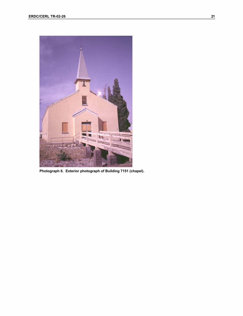
The chapel, Building 7151, is a one-story rectangular building, 37 ft wide by 96.5 ft long, or 3570 sq ft in plan area (Photograph 6). Drawing 2 presents the key plan used in discussion of the structure.
The building has an entry lobby on the south side that is flanked by two rooms. In the west room is located the stairs to the choir loft, which is located above the entry. Behind the altar, to the north of the nave, are sacristy and restroom. A boiler room is located at the north end of the building.
The foundation is reinforced concrete, with one row of interior piers running longitudinally down the centerline of the building. Wood joists frame the floor, bearing on the exterior foundation and interior piers. The exterior walls are terra cotta tile masonry with a stucco exterior finish. The roof structure consists of wood trusses that span the width of the building, purlins, and rafters.
The interior is finished mostly in painted plaster, with a knotty pine wainscot on the walls. The nave floor is finished pine. The roof trusses are exposed to the inte-rior and are a significant feature of the chapel’s design.
ERDC/CERL TR-02-26 21
Photograph 6. Exterior photograph of Building 7151 (chapel).

22 ERDC/CERL TR-02-26
Drawing 2. Building 7151 key plan.
Building 7151 is seriously contaminated by pigeon excrement. Researchers were reluctant to expose themselves to airborne contamination. Therefore, the following observations are made primarily from examination of the building’s exterior, with only cursory review of the chapel’s interior. Prolonged exposure to the closed inte-rior environment was inadvisable.
3.2 Condition Assessment
3.2.1 Substructure
The foundation walls were observed around the chapel’s perimeter from the exte-rior. Any occurrence of cracking, deformation, deflection in either horizontal or ver-tical plane, differential settlement, heaving, lateral displacement, leakage, concrete deterioration, exposed reinforcing, or other signs of distress were noted, and are de-scribed in the following paragraphs.
The grade slopes generally northwest-to-southeast and has built up onto the exte-rior wall at the north and west sides of the building. The foundation wall is visible at the east and south sides of the building. The crawl space was inaccessible due to the grade building up around the scuttles, and there is almost no clearance below the floor structure. Therefore, no observations of the foundation’s interior surfaces or components were made.

ERDC/CERL TR-02-26 23
The foundation system appears to be generally sound. The top of the wall remains level, at least where it remains above grade. No significant deformation or settle-ment was observed, although minor cracking occurs throughout the foundation and exterior walls near the foundation.
Some minor vertical cracking has occurred at the west wall and extend downward at the foundation (Drawing 2, A). The location of these cracks corresponds to the location of the pilasters supporting the roof trusses on the building’s interior. Some minor settlement or movement may have occurred at one time, opening these cracks. However, these cracks do not suggest any significant structural movement. Minor spalling was observed at the east side of the north boiler room wall (Drawing 2, B). The grade runs toward the building at this point. This minor cracking should be sealed during the exterior’s refinishing.
3.2.2 Superstructure
Structural components were examined in all locations of the building. Where fram-ing or load-bearing members were concealed, floor or wall assemblies were exam-ined for signs of distress. Any occurrence of cracking, deformation, deflection in ei-ther horizontal or vertical plane, differential settlement, lateral displacement, and other signs of distress in any load-bearing components were noted, and are de-scribed in the following paragraphs.
3.2.3 Floor Construction
The floors in the nave, sanctuary, and sacristy areas of the chapel did not exhibit any signs of extraordinary bounce or deflection when walking, bouncing, or jumping at any location. They appeared to be quite rigid under impact. The first floor re-mains reasonably level and did not exhibit any significant sagging or settlement. Because of inaccessibility of the crawl space, the floor structure could not be exam-ined from below.
The choir loft stairs and floor framing, likewise, appeared sound. No extraordinary bounce or deflection was observed in these areas. Framing members were concealed and could not be directly examined. However no deformations or water damage was observed, suggesting the structure was sound.

24 ERDC/CERL TR-02-26
3.2.4 Roof Construction
The primary roof structural members are wood trusses, which are supported at the exterior wall by pilasters. The roof was examined from the building’s exterior. The trusses and pilasters were examined from the building’s interior.
When viewed from the ground, the side of each gable appears to be generally flat and straight. The ridge also appears to be straight. Some minor sagging in the roof planes was evident between the trusses, although the roof at the trusses’ upper chords remains straight between the eaves and ridge.
The steeple roof appears sound from the exterior. No leaning, deflection, or other structural distress was evident. The ends of the steeple rafters are visible at the open eave. The rafter ends are aligned, with no signs of deflection or displacement. The planes and ridges appeared straight and true. Absence of the access ladder and pigeon contamination prevented examination of the steeple structure from the inte-rior.
From the interior, no evidence of deflection, deformation, or distress was observed in the trusses. The roof’s secondary structural members were concealed by the plas-ter ceiling. The ceiling surface did not exhibit any cracking or other evidence of movement or failure in the roof structure
The trusses bearing on the pilasters were concealed by the plaster finish. However, no cracking or crushing in the finish or pilasters, or other signs of compression or displacement in the trusses or pilasters was evident.
3.3 Exterior Closure
All exterior components were observed. Any occurrences of cracking, deformation, leakage, weathering, material deterioration, and other signs of distress in any wall or roof components were noted, as described in the following paragraphs.
3.3.1 Walls
The exterior wall system is generally sound. Few cracks in the stucco were ob-served, primarily on the chapel’s east wall. Also, no significant cracking, bowing, differential settling, or other signs of distress were observed.
ERDC/CERL TR-02-26 25
The aforementioned minor cracking at the east wall’s pilasters will have to be sealed. These cracks should then be monitored to see if they reappear.
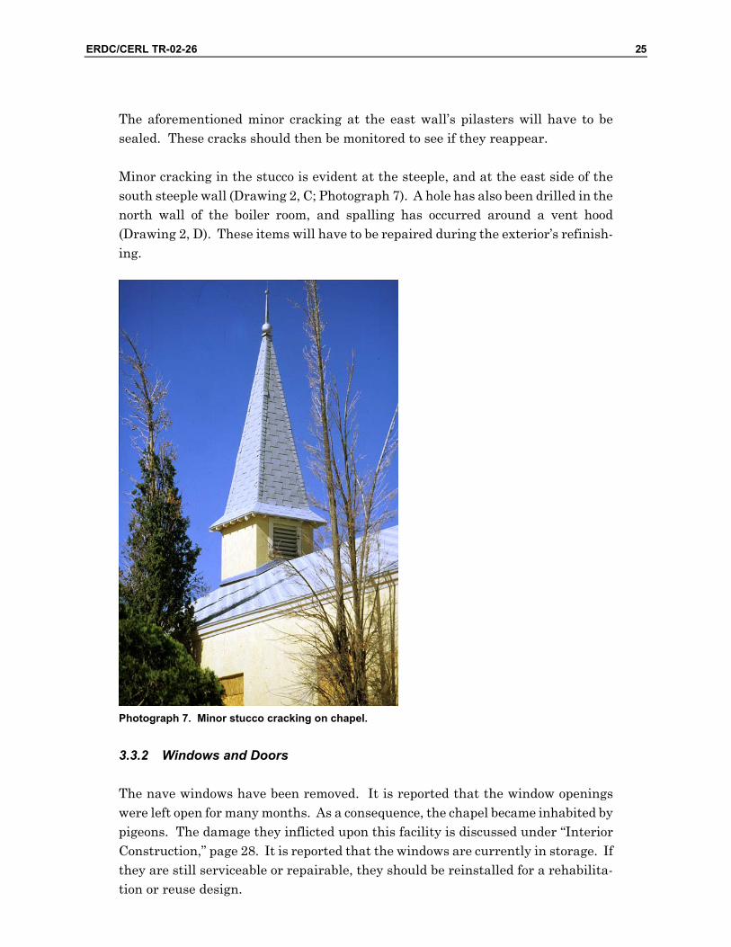
Minor cracking in the stucco is evident at the steeple, and at the east side of the south steeple wall (Drawing 2, C; Photograph 7). A hole has also been drilled in the north wall of the boiler room, and spalling has occurred around a vent hood (Drawing 2, D). These items will have to be repaired during the exterior’s refinish-ing.
Photograph 7. Minor stucco cracking on chapel.
3.3.2 Windows and Doors
The nave windows have been removed. It is reported that the window openings were left open for many months. As a consequence, the chapel became inhabited by pigeons. The damage they inflicted upon this facility is discussed under “Interior Construction,” page 28. It is reported that the windows are currently in storage. If they are still serviceable or repairable, they should be reinstalled for a rehabilita-tion or reuse design.

26 ERDC/CERL TR-02-26
Windows in the foyer areas and sacristy remain in place, although they are boarded on the exterior. They are double hung with six-over-six sashes. In general, they are intact and not seriously deteriorated. Amber colored textured glass appears to be the original glazing material. Many panes have been broken. Some have been re-placed with clear glass, and some have not been replaced at all. Serious damage was observed to only two sashes, apparently by vandalism (Drawing 2, E; Photograph 8). It should be possible to repair and refinish these windows. The window below the steeple on the south wall remains unboarded. It is intact, al-though it will require repair and refinishing.
Photograph 8. Damaged sacristy window sashes.
The glass was broken out of the aluminum entry door (Drawing 2, F). However, this door should be replaced with a historically appropriate style of entry in an adaptive use design.
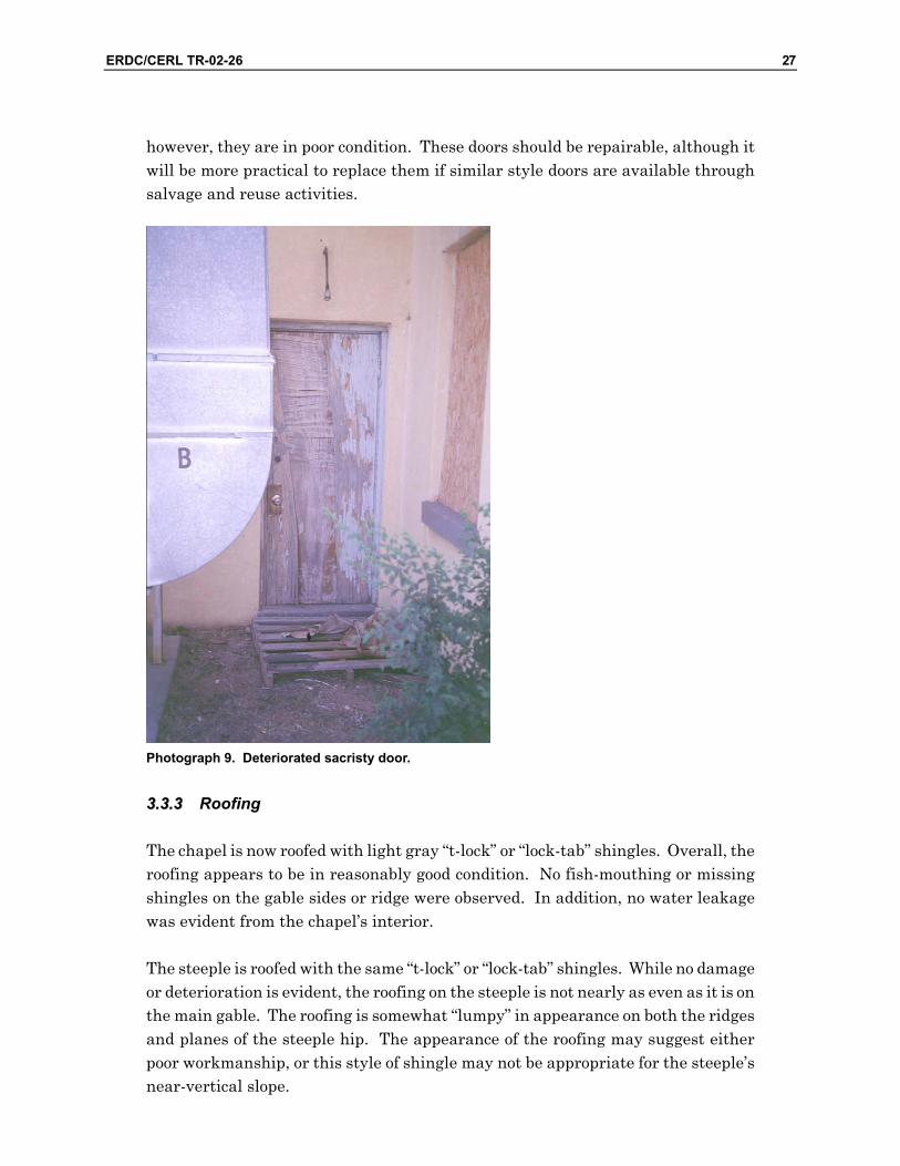
The exterior door on the west side of the sacristy had been replaced with a flush wood door, which is seriously deteriorated (Photograph 9). The doors on the east side of the sacristy and on the boiler room appear to be the original five-panel doors;
ERDC/CERL TR-02-26 27
however, they are in poor condition. These doors should be repairable, although it will be more practical to replace them if similar style doors are available through salvage and reuse activities.
Photograph 9. Deteriorated sacristy door.
33..33..33 Roofing
The chapel is now roofed with light gray “t-lock” or “lock-tab” shingles. Overall, the roofing appears to be in reasonably good condition. No fish-mouthing or missing shingles on the gable sides or ridge were observed. In addition, no water leakage was evident from the chapel’s interior.
The steeple is roofed with the same “t-lock” or “lock-tab” shingles. While no damage or deterioration is evident, the roofing on the steeple is not nearly as even as it is on the main gable. The roofing is somewhat “lumpy” in appearance on both the ridges and planes of the steeple hip. The appearance of the roofing may suggest either poor workmanship, or this style of shingle may not be appropriate for the steeple’s near-vertical slope.

28 ERDC/CERL TR-02-26
In an adaptive use design, the historical appropriateness of the shingle style must be determined. If the roofing will be replaced, consideration must be given to the type of shingle appropriate for the slope at the steeple.
Minor deterioration of the eave trim occurs around the building. For example, paint has failed at the fascia at the north end of the east wall, at the rake trim on the north gable end (Drawing 2, G; Photograph 10), and at the rake trim at the south gable end below the steeple (Drawing 2, H). Scraping, priming, and repainting should be an effective repair.
Photograph 10. Detail of paint failure on chapel trim.
3.4 Interior Construction
Partitions, finishes, doors and windows, and other interior construction were exam-ined visually. Cracking, movement, finish damage, and other signs of deterioration were noted, as described in the following paragraphs. Obvious removal or replace-ment of original features was also noted.
Pigeon excrement has defaced all of the Chapel’s interior spaces and surfaces. Car-casses lay everywhere.

ERDC/CERL TR-02-26 29
3.4.1 Partition Construction
The original partitioning at the lobby, altar, and sacristy areas remains intact.
Some cubicles have been added in the choir loft. It is assumed these will be re-moved with an adaptive reuse design.
Air conditioning ducts have been cut into the north wall of the nave on both east and west sides of the altar (Drawing 2, I). Cracks radiate from the opening’s cor-ners in a stair-step pattern (Photograph 11). While noticeable, these cracks are not major, and no serious deflection in the roof above or deformation in the wall has oc-curred. The wall appears to remain stable. The cracks will have to be filled.
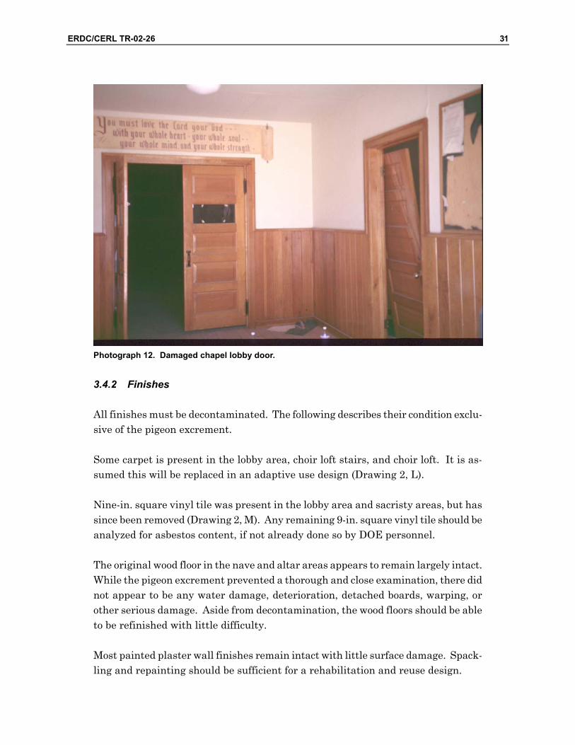
Most of the interior doors and trim remain in place; however, the east side interior lobby door has been removed from its original location and has been damaged, (Drawing 2, J). At present, the door remains in the room (Photograph 12). How-ever, the door and frame should be able to be repaired and refinished fairly easily.
A metal pipe rail is currently in place at the choir loft (Drawing 2, K). This is ap-parently a replacement for the original rail. A wood rail is in place in the “German Chapel” on Fort Bliss, which was recently rehabilitated.

30 ERDC/CERL TR-02-26
Photograph 11. Minor damage around chapel air conditioning duct.
ERDC/CERL TR-02-26 31
Photograph 12. Damaged chapel lobby door.
3.4.2 Finishes
All finishes must be decontaminated. The following describes their condition exclu-sive of the pigeon excrement.
Some carpet is present in the lobby area, choir loft stairs, and choir loft. It is as-sumed this will be replaced in an adaptive use design (Drawing 2, L).
Nine-in. square vinyl tile was present in the lobby area and sacristy areas, but has since been removed (Drawing 2, M). Any remaining 9-in. square vinyl tile should be analyzed for asbestos content, if not already done so by DOE personnel.
The original wood floor in the nave and altar areas appears to remain largely intact. While the pigeon excrement prevented a thorough and close examination, there did not appear to be any water damage, deterioration, detached boards, warping, or other serious damage. Aside from decontamination, the wood floors should be able to be refinished with little difficulty.
Most painted plaster wall finishes remain intact with little surface damage. Spack-ling and repainting should be sufficient for a rehabilitation and reuse design.

32 ERDC/CERL TR-02-26
A mural has been painted on the sanctuary’s north wall behind the altar (Drawing 2, N). If an occupancy other than religious purposes is found for this building, con-sideration should be given to either displaying this mural as an artifact of the build-ing’s original use, or shielding and protecting it.
A fiberboard wall surface has been applied to the room to the west of the lobby, around the underside of the choir loft stairs, and in the choir loft (Drawing 2, O). The condition of the plaster under the fiberboard is unknown. It is assumed that the fiberboard will be removed, and the plaster repaired or replaced with gypsum wallboard in an adaptive reuse design.
Knotty pine wainscot is present throughout the lobby, nave, and sacristy spaces. It is generally intact with little evidence of surface damage, detached boards, warping, or other serious defects.
The painted plaster ceiling surfaces in the lobby area, nave, and sacristy areas re-main generally intact. Spackling and repainting should be sufficient for a rehabili-tation and reuse design.
An area of gypsum wallboard has been added at the choir loft ceiling (Drawing 2, P). Some joints are delaminating. The gypsum wallboard can be repaired, or the under-lying plaster repaired in an adaptive reuse design.
An area of fiberboard ceiling above the altar has become detached. This does not appear to be caused by water leakage. This should be replaced in an adaptive reuse design.
3.4.3 Other Interior Construction
The cabinetry at the back of the sanctuary area remains largely intact, although other materials have been strewn in this area (Drawing 2, Q; Photograph 13). The doors are still in place and operable. This cabinetry should be serviceable with re-finishing. Alternatively, it can be removed if it is unsuitable for future occupancy.

ERDC/CERL TR-02-26 33
Photograph 13. Detail of chapel cabinetry.
3.5 Services
Very little could be determined about the condition, serviceability, and capacity of the plumbing, HVAC, and electrical systems. The observations are made with re-spect to upgrading these systems for a rehabilitation and reuse design.
3.5.1 Plumbing
Water service is active, as evidenced by a leaking spigot near the chapel’s entrance.
A washroom behind the sacristy includes a toilet and lavatory, and is the only washroom in the building (Drawing 2, R). These fixtures, however, were fouled and their serviceability was not tested. It is assumed that new fixtures will be used in a rehabilitation and reuse design. Alternatively, historically appropriate fixtures can be obtained through salvage and reuse activities.
34 ERDC/CERL TR-02-26
The Department of Public Works (DPW) reports the sanitary drain is original. If future occupancy requires additional fixtures, the capacity of this line to carry an additional burden must be verified.
3.5.2 Heating, Ventilating, and Air Conditioning (HVAC)
The performance of the boiler and air conditioning could not be determined. It is assumed that a rehabilitation and reuse design will also involve upgrading the HVAC system to accommodate future occupancy and the intended function.
According to the Department of Public Works and Logistics (DPWL), a 400,000 BTU gas-fired boiler was installed 8 years ago. The fan-coil heaters suspended from the roof structure are not original, and are reported to be operable. Two 10,000 CFM evaporative coolers had been added at the north side of the building, although only the cabinets remain at present. Therefore, there is currently no cooling in this building.
3.5.3 Electrical
Electrical service was active and lights in the nave were operable.
The light fixtures in the nave appear to be original wrought-iron style pendant lights with stained glass panels. These fixtures are a significant feature of the building’s original use and design. All but one of the light fixtures is still operable. Repairing and refinishing these fixtures should be accomplished with little problem.
Surface mounted incandescent fixtures remained in all the other spaces. No fluo-rescent fixtures were observed. Therefore, mercury (Hg) or PCB disposal should not be required.
DPWL reports that the electrical system has not been upgraded in 50 years. It is assumed that an adaptive use design will also involve upgrading of the power and lighting systems to accommodate future occupancy and intended function.
3.6 Sitework
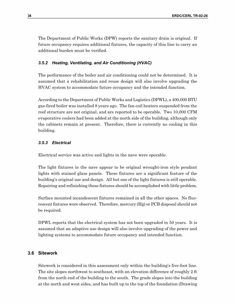
Sitework is considered in this assessment only within the building’s five-foot line. The site slopes northwest to southeast, with an elevation difference of roughly 2 ft from the north end of the building to the south. The grade slopes into the building at the north and west sides, and has built up to the top of the foundation (Drawing
ERDC/CERL TR-02-26 35
2, S; Photograph 14). No damage from water intrusion was evident in the building’s floor or wall finishes near the floor. However the crawl space vents at the building’s northwest corner were almost closed by the coarse soil carried by runoff, indicating runoff is entering the crawl space. Regrading to ensure positive drainage away from all sides of the buildings should be included as part of the adaptive use design.
Photograph 14. Chapel site drainage detail.
3.7 Recommendations
The chapel building is fundamentally sound. The structural systems appear to be performing as intended. With the exception of the absence of the nave’s windows, the exterior closure systems are generally intact. With the appropriate upgrades, repairs, and refinishing, the building should be completely serviceable.
The following tasks will be necessary for an adaptive use design. With the excep-tion of decontamination from pigeon droppings, these tasks are common and straightforward, and should be completed without great difficulty.
• Decontaminate the building’s interior. • Replace the nave windows, repairing and refinishing as necessary. • Repair and refinish the windows and frames in the sacristy and lobby areas.
Use the same glazing materials throughout these windows.
f ] 7151
H t^j

36 ERDC/CERL TR-02-26
• Repair and refinish the five-panel doors in the sacristy area and boiler room. Replacing some pieces may be necessary. Replace the flush wood door with a historically appropriate door. Refinish the door frames.
• Replace the aluminum entry with a historically appropriate entry. • Perform the necessary minor repairs to the exterior (stucco surfaces and
trim) and refinish. • If the roofing will be replaced as part of the adaptive reuse design, select a
historically appropriate style of shingle. Verify the appropriateness of the se-lected shingles for the near-vertical surfaces of the steeple.
• Regrade around the building, especially at the west and north sides, to en-sure positive drainage away from the foundation and prevent the build-up of soil over the top of the foundation wall. Protect the grade adjacent to the building with planting, rock blanket, or other surface that will prevent ero-sion and sediment build-up.
• Remove the partitioning from the choir loft. • Replace the pipe rail at the choir loft with a historically appropriate style, in
conformance to the prevailing safety standard for railings. • Replace the ceiling panels above the sanctuary, perform the required minor
repairs to interior components and finishes (doors, walls, ceilings, trim, and other interior features) and refinish.
• The treatment of the mural must be considered with regard to the building’s future occupancy. If a secular occupancy or activity dictates the mural should not be displayed, it should be protected and preserved, as opposed to being destroyed by repainting the sanctuary’s back wall.
• Refinish the wood floor in the nave. • Remove the other flooring finishes. Test the tiles in the foyer for asbestos
and, if they are asbestos containing, dispose of them according to State asbes-tos removal regulations. Replace flooring as appropriate for the spaces' occu-pancy and use.
• Depending on the building’s future occupancy, the HVAC system may require upgrading. In addition to servicing the interior spaces, as configured to fu-ture uses, air and steam distribution must also be designed with respect to the unique context of the building’s interior design.
• Additional restroom facilities will likely be required. • Electrical systems will require upgrading to meet prevailing standards.
Lighting, power, and electronic, systems will require upgrading to accommo-date future occupant’s function and activities. Consideration should be given to modularity and flexibility in reconfiguring lighting electrical distribution for future change in occupancy and function.
• Conformance to egress requirements will have to be verified. There should be a sufficient number of exits for a variety of occupancies. Dimensions,

ERDC/CERL TR-02-26 37
hardware, other egress provisions will require upgrading to prevailing fire safety standards.
The chapel’s interior is unique within an otherwise utilitarian architectural envi-ronment of the WBGHHD. While the ecclesiastical casework will likely be removed, the elegance of the space, roof structure, and woodwork can be recaptured. The clear dimensions of the nave would provide flexibility to accommodate a variety of community-types of activities and functions.

38 ERDC/CERL TR-02-26
4 Building 7152: Theater
44..11 Description
The theater is a one-story rectangular building, 37 ft wide by 99 ft long, or 3663 sq ft in plan area. It was recently remodeled and is being used for lectures and train-ing.
An entry lobby on the south side of the building includes washrooms and an office. The theater floor is inclined toward a stage at the north end of the theater. A boiler room is located at the north end of the building.
The foundation and floor slab are reinforced concrete. The exterior walls are terra cotta tile masonry with a stucco exterior finish. The roof structure consists of wood trusses, purlins, and rafters.
The interior is finished mostly in painted plaster or gypsum wallboard, with acous-tic material applied to the theater walls. The original ceiling is painted plaster, and a suspended acoustical ceiling system now hangs below that.
An exterior photograph of Building 7152 is shown in Photograph 15. Drawing 3 presents the key plan used in discussion of the structure.
The theater building is currently being used as an assembly / classroom building. The interior has been remodeled to its current configuration within the past 10 years. Occupants report that the building is performing as intended.

ERDC/CERL TR-02-26 39
Photograph 15. Exterior photograph of Building 7152 (theater).
Drawing 3. Building 7152 key plan.
40 ERDC/CERL TR-02-26
4.2 Condition Assessment
4.2.1 Substructure
The foundation walls were observed around the theater’s perimeter from the exte-rior. The foundation was covered by the grade at the north wall, and north end of the west wall, but is still visible at the remainder of the building’s perimeter. Any occurrence of cracking, deformation, deflection in either horizontal or vertical plane, differential settlement, heaving, lateral displacement, leakage, concrete deteriora-tion, exposed reinforcing, or other signs of distress were noted, as described in the following paragraphs.
The top of the foundation wall is level, and there is no evidence of settlement or dis-placement.
A lateral crack occurs at the east wall at the interface of the foundation and exterior wall (Drawing 3, A). However, there is no lateral displacement of the wall off of the foundation. This crack will have to be sealed during exterior refinishing.
The stoop that is located at the exit on the east side of the building is badly cracked (Drawing 3, B) and its corners appear to be settling. While it may be possible to re-pair the stoop, replacing it may be more practical.
The floor slab at the vestibule is cracked longitudinally (Drawing 3, C). No other evidence of movement in this slab was observed. It may be possible this crack was not filled or smoothed prior to installation of the current flooring, and the crack is now showing through the flooring.
4.2.2 Superstructure
Structural components were examined in all locations of the building. Where fram-ing or load-bearing members were concealed, floor or wall assemblies were exam-ined for signs of distress. Any occurrence of cracking, deformation, deflection in ei-ther horizontal or vertical plane, differential settlement, lateral displacement, and other signs of distress in any load-bearing components were noted, and are de-scribed in the following paragraphs.
4.2.3 Floor Construction
A second floor is framed over the south end of the building for control and projection rooms. These spaces are no longer used for these purposes. The stairs and the floor

ERDC/CERL TR-02-26 41
appear to be sound with no extraordinary deflection or bouncing when walking, jumping, or bouncing. No cracking in the ceilings or excessive deflection was ob-served from below.
4.2.4 Roof Construction
The wood truss structure was concealed by an original plaster ceiling with a sus-pended acoustical ceiling hanging below the original.
When viewed from the ground, the side of each gable appears to be quite flat and straight. The ridge also appears to be straight. No sagging was evident in any part of the roof.
A flat canopy extends over the south end of the building to shelter the entry (Drawing 3, D). The roof itself appears sound, although its supporting columns are split at the bottoms, some severely. It is not known whether this roof is an original feature of the theater’s design because the roof appears to be an addition but it is visible on aerial photographs taken prior to WWII. Porch roofs on other buildings are low slope hip shapes. The roof is well flashed at the interface with the build-ing’s south wall. If this roof is retained in future rehabilitation designs, the col-umns will have to be repaired and/or replaced. Increasing the pitch for drainage should also be considered.
4.3 Exterior Closure
44..33..11 Walls
The exterior walls are in generally good condition. Minor cracking occurs around a metal vent hood at the north wall (Drawing 3, E; Photograph 16), around a light fix-ture over the east exit (Drawing 3, F), at pipe penetrations at the east wall (Drawing 3, G), and around the south exit at the west wall (Drawing 3, H). Louvers and grills on the north wall will require minor repair and refinishing. These repairs should present no problems when refinishing the exterior.

42 ERDC/CERL TR-02-26
Photograph 16. Minor theater wall cracking around vent hood.
4.3.2 Windows and Doors
The windows in the office and washroom areas on the south end of the building are intact. The washroom panes are painted. While none of the windows are in good condition, all windows can be repaired and refinished.
All exterior doors and frames have been replaced with flush metal personnel doors and metal frames. If the exterior is to be rehabilitated, a historically appropriate style of door will have to be found to replace existing metal doors.
4.3.3 Roofing
The theater is now roofed with light gray “t-lock” or “lock-tab” shingles. Overall, the roofing appears to be in reasonably good condition. While no water leakage was evident when viewed from below, the fiberglass insulation installed in the attic space may mask minor leakage.
Since re-roofing is common in a rehabilitation and reuse program, the historic ap-propriateness of the existing style of shingle will have to be determined.
The roof that is sheltering the entry at the south wall is built-up with gravel ballast. If the slope of this roof is increased for drainage purposes, an alternative roofing
ERDC/CERL TR-02-26 43
material should be considered. If the roof is rebuilt to a low slope hip shape, similar to adjacent buildings, metal roofing is recommended.
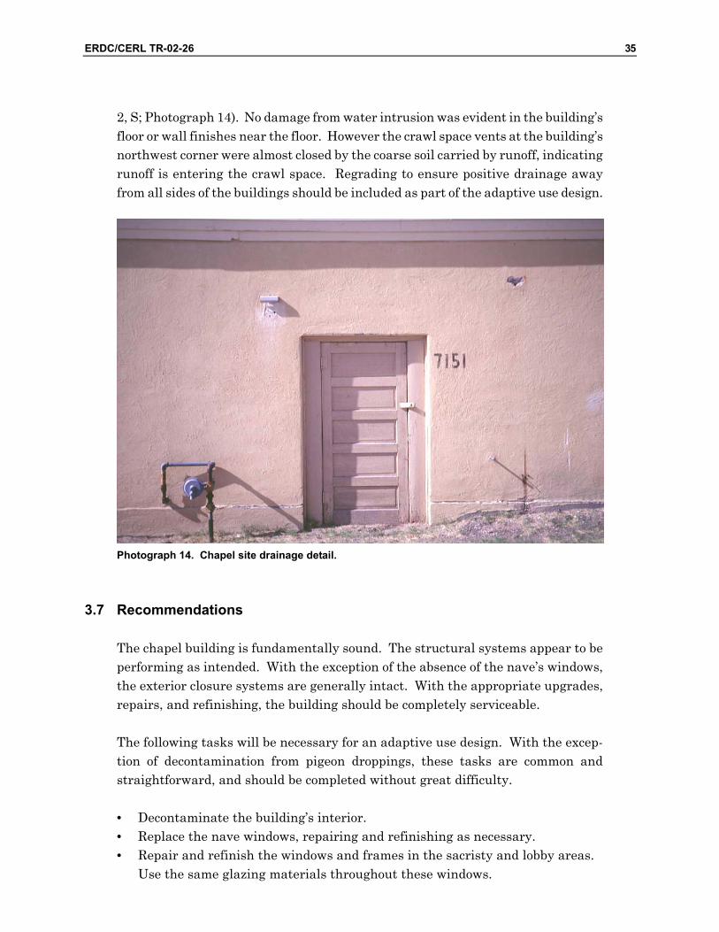
Some minor deterioration is evident in the eave trim (Photograph 17). Splitting has occurred in the rake board at the west end of the north eave, and in the fascia board at the north end of the west eave. Also, the fascia around the porch roof over the entry is badly peeled. However, scraping, filling, priming, and painting should be sufficient to rehabilitate these areas.
Photograph 17. Deterioration of theater eave trim.
4.4 Interior Construction
It is assumed that the current interior configuration will remain. Therefore, no ex-tended discussion will be made about apparent modifications to the building’s plan or description of existing features.
All partition construction appears to be sound. Five-panel doors remain in the ves-tibule and washroom area. An innovative vent detail has been incorporated into the washroom doors (Photograph 18). Also, a new flush metal door is in place adjacent to the stage.

44 ERDC/CERL TR-02-26
Photograph 18. Theater washroom door vent detail.
All finishes are in good condition. The vinyl composition tile flooring is sound, with the exception of the aforementioned cracking in the vestibule. All painted plaster or gypsum wallboard wall finishes are sound. Carpet and acoustic panels also appear on the auditorium walls. The ceiling finishes are clean with the exception of two stains attributed to leaks. There is evidence that a sprinkler pipe has leaked over the vestibule, although DPWL personnel report this leak has been repaired. There is also evidence of a leak in the auditorium towards the stage (Drawing 3, I), how-ever its origin could not be determined.
The former control and projection rooms are generally unfinished, although nothing is deteriorating or damaged. Only the rubber tread surface of the stairs is failing.

ERDC/CERL TR-02-26 45
4.5 Services
Plumbing, HVAC, and electrical services were reported to be serviceable and gener-ally perform as intended. All plumbing fixtures and lighting were found to be oper-able.
4.6 Sitework
Sitework is considered in this assessment only within the building’s five-foot line. The site slopes north to south, with an elevation difference of roughly 1 ft from the north end of the building to the south. The grade slopes into the building at the north and west sides, and has built up above the top of the foundation (Drawing 3, J). Water intrusion from runoff does not appear to have damaged the building. However, regrading should be conducted on all sides of the building to ensure posi-tive drainage away from the building to prevent future water intrusion problems.
4.7 Recommendations
It is assumed the theater will remain in its current occupancy and configuration. This building should remain completely serviceable in its present condition. How-ever, the following tasks would be appropriate for an exterior renovation, to be con-sistent with the adjacent building’s upgrades. These tasks are common and straightforward, and should be completed without great difficulty.
• Replace the stoop at the east door. • Upgrade the porch at the building’s entry. As a minimum, replace the col-
umns. Also, consider installing low-slope metal roofing to improve drainage and to be consistent (without duplicating) the porch roof detailing depicted in the surrounding building’s original designs.
• Repair and refinish the windows and frames in the entry, office, and restroom areas. Use frosted glazing materials for the restroom windows.
• Perform the necessary minor repairs to the exterior (stucco surfaces and trim) and refinish.
• If the roofing will be replaced as part of the adaptive use design, select a his-torically appropriate style of shingle.
• If not already done, seal the leak in the sprinkler piping at the entry. De-termine whether the leak over the auditorium seating is from sprinkler pip-ing and, if so, seal it.

46 ERDC/CERL TR-02-26
• Regrade around the building, especially on the west and north sides, to en-sure positive drainage away from the foundation and to prevent the build-up of soil over the top of the foundation wall. Protect the grade adjacent to the building with planting, rock blanket, or other surface that will prevent ero-sion and sediment build-up.

ERDC/CERL TR-02-26 47
5 Building 7155: Gymnasium
5.1 Description
The gymnasium is a one-story rectangular building, 60 ft wide by 119 ft long, or 7140 sq ft in plan area.
The building has an entry lobby on the south side that is flanked by two offices. Locker / shower rooms are located to the west of the gymnasium. The gymnasium itself consists of one full-size basketball court. An elevated spectator gallery wraps around the west and south sides of the gymnasium, above the lobby and locker / shower areas. An elevated stage is located at the north end of the building, and at one time was open to the gymnasium.
The foundation and floor slab are reinforced concrete. Wood floor joists frame the gymnasium area of the building. Wood floor joists frame the spectator gallery. The exterior walls are terra cotta tile masonry with a stucco exterior finish. The roof structure consists of steel trusses and wood purlins and rafters, the trusses span the width of the building.
The lobby areas are finished in painted plaster. The remainder of the spaces are finished in painted brick. The gymnasium floor is hard maple. The roof structure is exposed to the interior and is a significant feature of the gymnasium design.
An exterior photograph of Building 7155 is shown in Photograph 19, and the key plan is illustrated in Drawing 4.

48 ERDC/CERL TR-02-26
Photograph 19. Exterior photograph of Building 7155 (gymnasium).
Drawing 4. Building 7155 key plan.
5.2 Condition Assessment
5.2.1 Substructure
The foundation walls were observed around the gymnasium’s perimeter from the exterior of the building. The top of the foundation walls remains visible at the south

ERDC/CERL TR-02-26 49
side, north side, and most of the west side of the gymnasium. The foundation is concealed by the grade at the north end of the west wall and by the handicapped ramp on the east side. Any occurrence of cracking, deformation, deflection in either horizontal or vertical plane, differential settlement, heaving, lateral displacement, leakage, concrete deterioration, exposed reinforcing, or other signs of distress were noted, and are described in the following paragraphs.
5.2.1.1 Foundation Construction
The foundation system appears to be generally sound. The top of the wall remains level at the main part of the gymnasium and around the stage. No significant de-formation or settlement was observed.
Minor cracking occurs throughout the foundation. A crack appears at the east wall, tracing from the lower corner of a crawl space vent, through the wall, and into the foundation (Drawing 4, A; Photograph 20). However, no differential movement or settlement was evident. This minor cracking should be sealed as part of the exte-rior refinishing. As the cracking appears to have not progressed for some period of time, repair should remain effective.
Photograph 20. Minor gymnasium foundation cracking.
Concrete has spalled at the tops of two foundation pilasters on the north side of the building, adjacent to the loading dock (Photograph 21). Minor cracking in the wall pilasters was observed, although no settlement has occurred.

50 ERDC/CERL TR-02-26
Photograph 21. Minor gymnasium pilaster cracking.
Cracks are present throughout the loading dock (Drawing 4, B). The deck slab is badly cracked, especially at the corners where the pipe railing has rusted and spalled away the concrete (Photograph 22). The slab is also deteriorated around the edges where anchor bolts held wood bumpers. The bumpers themselves are almost totally deteriorated, and the anchor bolts are exposed. Impact from vehicles may also have contributed to cracking and eventual deterioration. Repair of the loading dock may be possible, although replacement may be more feasible.

ERDC/CERL TR-02-26 51
Photograph 22. Concrete damage on gymnasium loading dock.
Water intrusion is evident in the locker / shower room at the north end of the build-ing. The floor slab is below grade at this location, and water apparently is entering at the foundation. This condition is discussed under “Walls,” page 53.
5.2.1.2 Slab on Grade
The floor slabs in the lobby areas, locker rooms, and stage were observed. Surface features of the slab are visible through the floor finish. These slabs appeared to be level and sound. No significant cracking, settling, or displacement out-of-plane was observed.
The stage slab is inclined slightly from the back of the stage (north) to the front of the stage (south) (Drawing 4, C). This incline is shown on the original drawings. The stage slab surface is somewhat irregular (i.e., slightly lumpy), but did not ex-hibit any serious deformations. If future occupancy requires a dead-level floor, a topping can be poured over the existing slab, once the flooring and residual mastic has been removed.
5.2.2 Superstructure
Structural components were examined in all locations of the building. Where framing or load-bearing members were concealed, floor or wall assemblies were
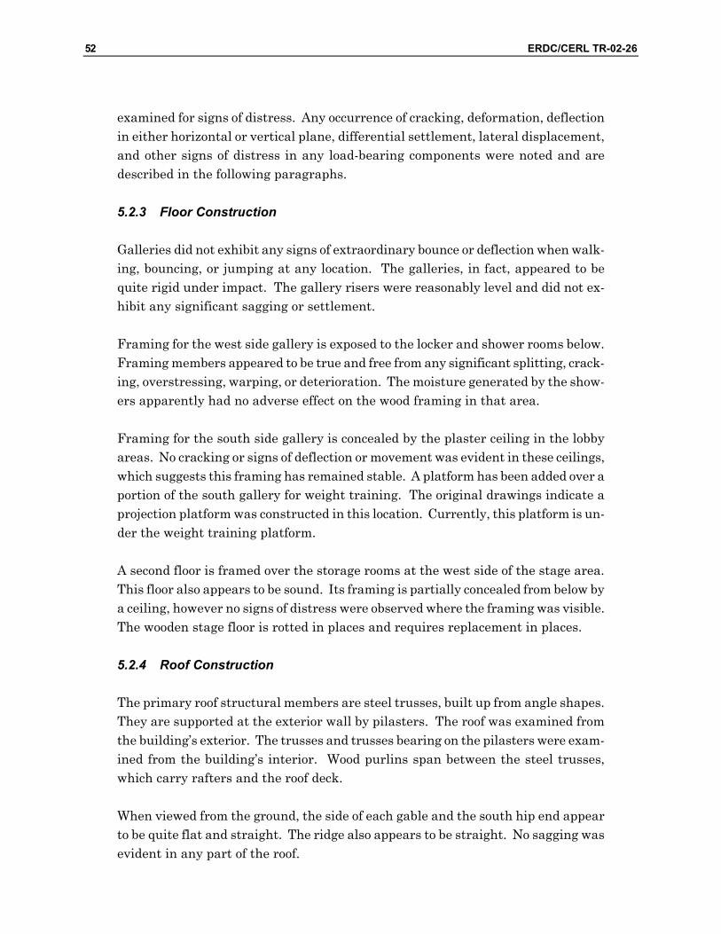
52 ERDC/CERL TR-02-26
examined for signs of distress. Any occurrence of cracking, deformation, deflection in either horizontal or vertical plane, differential settlement, lateral displacement, and other signs of distress in any load-bearing components were noted and are described in the following paragraphs.
5.2.3 Floor Construction
Galleries did not exhibit any signs of extraordinary bounce or deflection when walk-ing, bouncing, or jumping at any location. The galleries, in fact, appeared to be quite rigid under impact. The gallery risers were reasonably level and did not ex-hibit any significant sagging or settlement.
Framing for the west side gallery is exposed to the locker and shower rooms below. Framing members appeared to be true and free from any significant splitting, crack-ing, overstressing, warping, or deterioration. The moisture generated by the show-ers apparently had no adverse effect on the wood framing in that area.
Framing for the south side gallery is concealed by the plaster ceiling in the lobby areas. No cracking or signs of deflection or movement was evident in these ceilings, which suggests this framing has remained stable. A platform has been added over a portion of the south gallery for weight training. The original drawings indicate a projection platform was constructed in this location. Currently, this platform is un-der the weight training platform.
A second floor is framed over the storage rooms at the west side of the stage area. This floor also appears to be sound. Its framing is partially concealed from below by a ceiling, however no signs of distress were observed where the framing was visible. The wooden stage floor is rotted in places and requires replacement in places.
5.2.4 Roof Construction
The primary roof structural members are steel trusses, built up from angle shapes. They are supported at the exterior wall by pilasters. The roof was examined from the building’s exterior. The trusses and trusses bearing on the pilasters were exam-ined from the building’s interior. Wood purlins span between the steel trusses, which carry rafters and the roof deck.
When viewed from the ground, the side of each gable and the south hip end appear to be quite flat and straight. The ridge also appears to be straight. No sagging was evident in any part of the roof.
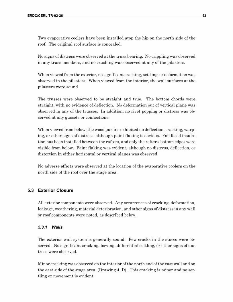
ERDC/CERL TR-02-26 53
Two evaporative coolers have been installed atop the hip on the north side of the roof. The original roof surface is concealed.
No signs of distress were observed at the truss bearing. No crippling was observed in any truss members, and no crushing was observed at any of the pilasters.
When viewed from the exterior, no significant cracking, settling, or deformation was observed in the pilasters. When viewed from the interior, the wall surfaces at the pilasters were sound.
The trusses were observed to be straight and true. The bottom chords were straight, with no evidence of deflection. No deformation out of vertical plane was observed in any of the trusses. In addition, no rivet popping or distress was ob-served at any gussets or connections.
When viewed from below, the wood purlins exhibited no deflection, cracking, warp-ing, or other signs of distress, although paint flaking is obvious. Foil faced insula-tion has been installed between the rafters, and only the rafters’ bottom edges were visible from below. Paint flaking was evident, although no distress, deflection, or distortion in either horizontal or vertical planes was observed.
No adverse effects were observed at the location of the evaporative coolers on the north side of the roof over the stage area.
5.3 Exterior Closure
All exterior components were observed. Any occurrences of cracking, deformation, leakage, weathering, material deterioration, and other signs of distress in any wall or roof components were noted, as described below.
5.3.1 Walls
The exterior wall system is generally sound. Few cracks in the stucco were ob-served. No significant cracking, bowing, differential settling, or other signs of dis-tress were observed.
Minor cracking was observed on the interior of the north end of the east wall and on the east side of the stage area. (Drawing 4, D). This cracking is minor and no set-tling or movement is evident.

54 ERDC/CERL TR-02-26
The original service entry at the north end of the stage area had been altered. The rough opening dimensions were decreased and a smaller door was installed. Cracks outlining the original opening are visible in the wall. However, no movement or dis-location of the masonry is evident. If this portal is not returned to its original con-figuration in a rehabilitation design, this cracking will have to be repaired.
Holes were drilled on the east wall for grates, which have since been removed. This damage will have to be repaired (Drawing 4, E).
A fire escape stair structure has been added to the south end of the east wall (Drawing 4, F; Photograph 23). The stairs have been removed, but the tower struc-ture remains. It is assumed that this structure will be removed and replaced in a rehabilitation design. The damage to the wall from the structure’s anchor bolts will have to be repaired.
Photograph 23. Unused gymnasium fire escape tower.
A fire escape stair structure has also been added to the north end of the west wall, but has since been removed (Drawing 4, G; Photograph 24). It is assumed that this

ERDC/CERL TR-02-26 55
structure will be replaced in some fashion in a rehabilitation design. The damage to the wall from the removed structure will have to be repaired.
Photograph 24. Gymnasium wall damage where fire escape was removed.
Water seepage is evident in the shower / locker rooms on the north end of the west wall. The floor slab is below grade at this location (Drawing 4, H). The original drawings of the west elevation depict the finished grade below the top of the founda-tion wall along the length of this wall. Apparently, over time, the grade has built up several inches over the top of the foundation at this end of the building, and no longer drains away from the building. The top of the stain on the interior of this wall approximates the current grade line. It is, therefore, likely that seepage occurs through the wall at the current grade line. Regrading around the building should eliminate this path of water intrusion.
Pipe rails currently protect the entry stairs at the south side of the building. The railings are in generally sound condition. The original drawings do not depict any railing. The historical appropriateness of the existing railing must be determined. If it is to remain, it will require routine maintenance in the form of refinishing.

56 ERDC/CERL TR-02-26
5.3.2 Windows and Doors
Windows are generally intact throughout the building. Frames appear to be in overall good condition, although repairs and refinishing will be necessary in a reha-bilitation or reuse design. No significant leakage around window frames was ob-served.
Reflective film has been installed on the glass panes. At present, many of the panes have been replaced without replacing the film (Photograph 25). In a rehabilitation or reuse design, film should be either restored to all glazing, or should be removed altogether.
Photograph 25. Inconsistent use of film on gymnasium windows.
Many panes have been broken throughout the building but not replaced, especially in the east and west walls. As a result, a sizeable pigeon population now inhabits this building.
The windows at both levels of the storage rooms on the northwest corner of the building have been boarded over. The frames and glazing are intact, although they are painted over on the inside surface. The two windows on the north wall of the stage area are likewise boarded over from the exterior.

ERDC/CERL TR-02-26 57
The triple sets of double-leaf doors at the south entry are a significant element of the original south elevation (Drawing 4, I). The doors have been replaced with flush wood doors, which are seriously deteriorated (Photograph 26). These will have to be replaced with a historically appropriate style of door. Two-panel doors are depicted on the original drawings. The transoms above the entry doors are intact, although repair and refinishing will be necessary.
Photograph 26. Deteriorated gymnasium entry doors.
The ground level exit doors on both the east and west sides of the gymnasium have been replaced with flush wood doors, which are also somewhat deteriorated. Three-panel doors with a vision panel are depicted in the original drawings. The transoms above these doors are also intact.
Fire exit doors have been added for the gallery on the east and west sides of the building. The doors have been framed into original window openings. The doors are flush wood doors. A reuse design will require at least two means of egress at this level, depending on the building’s occupancy. The selection of a door style and de-tailing of the exits will have to be developed in consideration of the overall fenestra-tion scheme and detailing of the building.

58 ERDC/CERL TR-02-26
5.3.3 Roofing
The original drawings do not indicate an original roofing material, but show only a “prepared roofing” note. No pattern or roofing material is shown. The gymnasium is now roofed with light gray “t-lock” or “lock-tab” shingles. Overall, the roofing ap-pears to be in reasonably good condition. No water leakage was evident when viewed from below. However, the fiberglass batt insulation that was installed over the entire roof’s interior surface can mask minor leakage.
The batt insulation installed between rafters appears to be intact. It is, however, unsightly and inconsistent with the overall character of the gymnasium’s roof fram-ing system. Whether this insulation remains in place, is removed, or is replaced with a different material must be considered along with the HVAC upgrade in-cluded in a rehabilitation or reuse design.
Re-roofing is common in a rehabilitation and reuse program. The historic appropri-ateness of the existing style of shingle will have to be determined. If the existing roofing is judged to be appropriate for an exterior restoration, some repair will be necessary.
There is serious damage at the south eave (Drawing 4, J) caused by tree branches that overhang the south hip at the building’s corners and are abrading the roofing (Photograph 27). Damage has occurred to both the roofing and the eave trim. The roofing in this area will have to be replaced, and the eave trim repaired and refin-ished. The louver at the south hip will also require scraping, priming, and painting.

ERDC/CERL TR-02-26 59
Photograph 27. Gymnasium roof abrasion.
Some fish-mouthing is evident near the east and west eaves (Drawing 4, K, Photograph 28). That is, some shingles are bent so they are not laying flat upon the roof deck or the shingles below them. The metal edge flashing of the roof sheathing is also damaged in one location on the east side (Drawing 4, L). In addition, some shingles are missing at the south end of the ridge (Drawing 4, M).
~r ■:■-'.. -i/^
4.J
V#
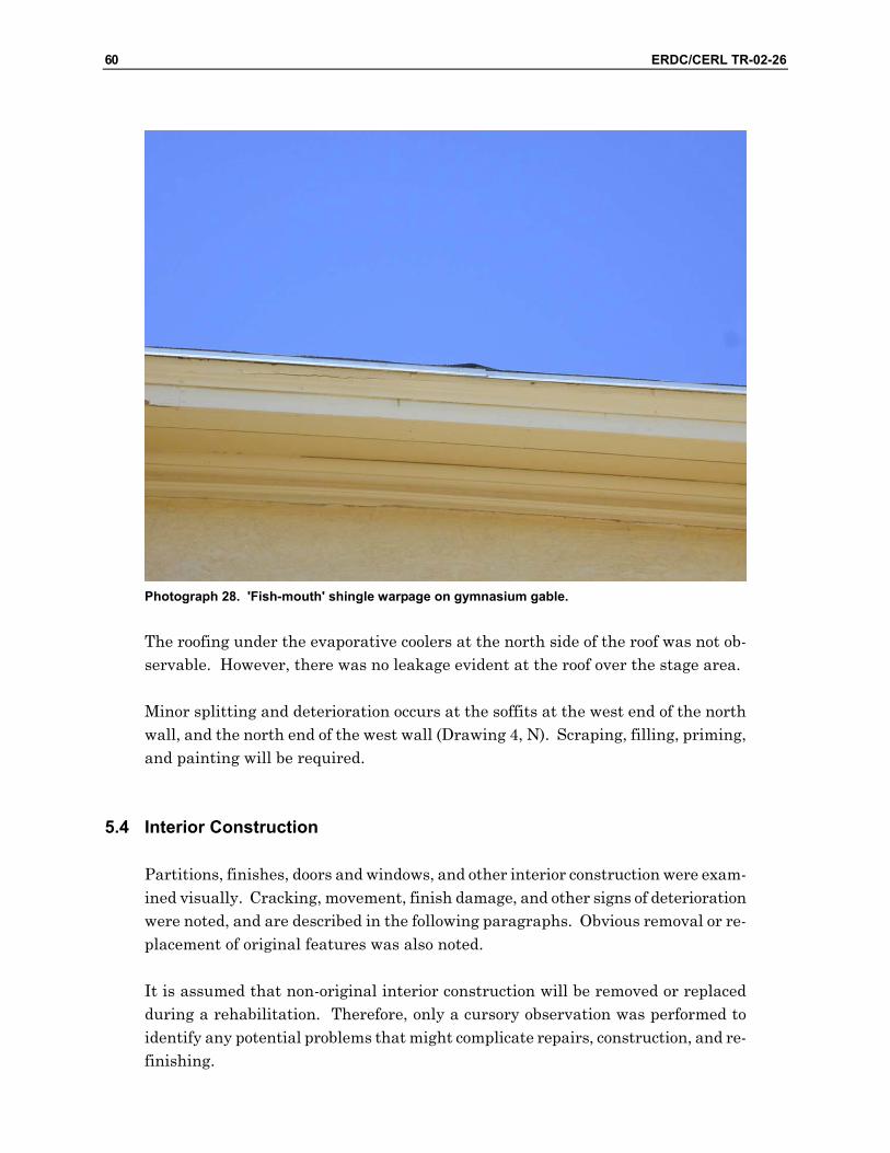
60 ERDC/CERL TR-02-26
Photograph 28. 'Fish-mouth' shingle warpage on gymnasium gable.
The roofing under the evaporative coolers at the north side of the roof was not ob-servable. However, there was no leakage evident at the roof over the stage area.
Minor splitting and deterioration occurs at the soffits at the west end of the north wall, and the north end of the west wall (Drawing 4, N). Scraping, filling, priming, and painting will be required.
5.4 Interior Construction
Partitions, finishes, doors and windows, and other interior construction were exam-ined visually. Cracking, movement, finish damage, and other signs of deterioration were noted, and are described in the following paragraphs. Obvious removal or re-placement of original features was also noted.
It is assumed that non-original interior construction will be removed or replaced during a rehabilitation. Therefore, only a cursory observation was performed to identify any potential problems that might complicate repairs, construction, and re-finishing.
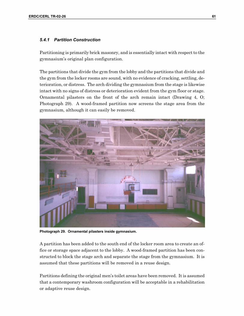
ERDC/CERL TR-02-26 61
5.4.1 Partition Construction
Partitioning is primarily brick masonry, and is essentially intact with respect to the gymnasium’s original plan configuration.
The partitions that divide the gym from the lobby and the partitions that divide and the gym from the locker rooms are sound, with no evidence of cracking, settling, de-terioration, or distress. The arch dividing the gymnasium from the stage is likewise intact with no signs of distress or deterioration evident from the gym floor or stage. Ornamental pilasters on the front of the arch remain intact (Drawing 4, O; Photograph 29). A wood-framed partition now screens the stage area from the gymnasium, although it can easily be removed.
Photograph 29. Ornamental pilasters inside gymnasium.
A partition has been added to the south end of the locker room area to create an of-fice or storage space adjacent to the lobby. A wood-framed partition has been con-structed to block the stage arch and separate the stage from the gymnasium. It is assumed that these partitions will be removed in a reuse design.
Partitions defining the original men’s toilet areas have been removed. It is assumed that a contemporary washroom configuration will be acceptable in a rehabilitation or adaptive reuse design.

62 ERDC/CERL TR-02-26
The original design depicts the following:
• A single door providing access from the lobby to the gym. • A set of three double-leaf doors providing access from the lobby to the gym. • A double-leaf door between the office area and the gym. • A single door to the locker room at both the north and south ends of the gym.
The single door from the lobby to the gym and the north locker room door remain intact. The others have been removed and the openings filled (Drawing 4, P). Pad-ding is installed on the gym walls. The door trim remains, although it has been painted. These portals, especially the former entrance from the lobby, are signifi-cant elements in the building’s design (Photograph 30). It would be possible to re-store these doorways if historically appropriate replacements can be found for the doors. In deciding such a rehabilitation measure, items such as the building’s fu-ture occupancy, must be considered, especially with regard to the building’s func-tion, safety, and circulation.
Photograph 30. Historically incompatible modifications of gymnasium locker room portal.
At least two original five-panel doors, or doors of similar vintage, are still in place. The remainder have been removed or replaced.
The original design depicts a small ticket window between the office and the lobby. This window has been filled, although the original outline is visible. This, too, would seem to be a noteworthy feature of the building’s original function and de-
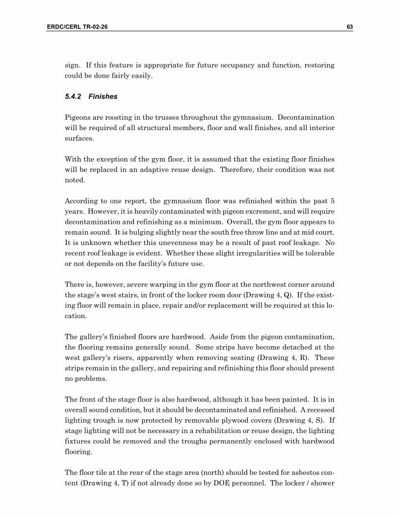
ERDC/CERL TR-02-26 63
sign. If this feature is appropriate for future occupancy and function, restoring could be done fairly easily.
5.4.2 Finishes
Pigeons are roosting in the trusses throughout the gymnasium. Decontamination will be required of all structural members, floor and wall finishes, and all interior surfaces.
With the exception of the gym floor, it is assumed that the existing floor finishes will be replaced in an adaptive reuse design. Therefore, their condition was not noted.
According to one report, the gymnasium floor was refinished within the past 5 years. However, it is heavily contaminated with pigeon excrement, and will require decontamination and refinishing as a minimum. Overall, the gym floor appears to remain sound. It is bulging slightly near the south free throw line and at mid court. It is unknown whether this unevenness may be a result of past roof leakage. No recent roof leakage is evident. Whether these slight irregularities will be tolerable or not depends on the facility’s future use.
There is, however, severe warping in the gym floor at the northwest corner around the stage’s west stairs, in front of the locker room door (Drawing 4, Q). If the exist-ing floor will remain in place, repair and/or replacement will be required at this lo-cation.
The gallery’s finished floors are hardwood. Aside from the pigeon contamination, the flooring remains generally sound. Some strips have become detached at the west gallery’s risers, apparently when removing seating (Drawing 4, R). These strips remain in the gallery, and repairing and refinishing this floor should present no problems.
The front of the stage floor is also hardwood, although it has been painted. It is in overall sound condition, but it should be decontaminated and refinished. A recessed lighting trough is now protected by removable plywood covers (Drawing 4, S). If stage lighting will not be necessary in a rehabilitation or reuse design, the lighting fixtures could be removed and the troughs permanently enclosed with hardwood flooring.
The floor tile at the rear of the stage area (north) should be tested for asbestos con-tent (Drawing 4, T) if not already done so by DOE personnel. The locker / shower

64 ERDC/CERL TR-02-26
room floor slabs have a topping that visually resembles oxychloride flooring (Drawing 4, U). Oxychloride is an asbestos-containing material. If these tiles are found to contain asbestos, they will have to be either encapsulated or removed and disposed of, in accordance with the prevailing State environmental regulations.
The painted plaster wall and ceiling finish in the lobby appear to be sound. Very little wear or surface damage was observed. No other significant soft spots, crack-ing, efflorescence, or other surface defects are evident.
The painted brick wall finish in the gym appears to be sound in all locations. The existing graphics may be reconsidered in a rehabilitation or reuse design. The exist-ing padding around the gym’s perimeter is not damaged, although it may not be ac-ceptable in the context of a rehabilitation or reuse.
The wall finish in the stage area is painted brick, with joints that are untooled and unfinished in appearance. If a rehabilitation and reuse design involves a more for-mal use for this space, the brick veneer can be pointed, tooled, and painted to pro-vide a higher level of finish than is presently in place.
The shower / locker room wall finishes are painted brick. With the exception of the seepage staining and paint blistering, they appear to remain sound. Very little flak-ing, blistering, or other surface defects were observed. An upgraded washroom facility, however, will likely use wall finishes that are better suited to wet environ-ments than painted brick, at least in part. The brickwork should provide a suitable base for another applied finish.
The existing wall paneling in the office area and room to the west of the lobby will have to be removed in rehabilitation or reuse design.
5.4.3 Other Interior Construction
The gallery rails are only 30 in. high, and allow passage of objects greater than 6 in. in diameter. The rails will have to be replaced by railings conforming to the prevail-ing building code.
The existing seating in the gallery is heavily contaminated by pigeon excrement. The seats will have to be thoroughly cleaned or replaced with appropriate seating. Alternatively, if seating is not required for the future occupancy and function, it can be removed and the hardwood risers refinished.
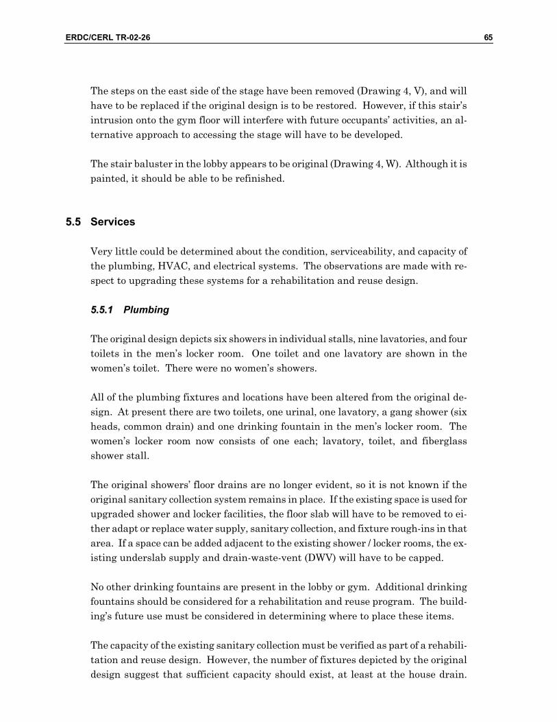
ERDC/CERL TR-02-26 65
The steps on the east side of the stage have been removed (Drawing 4, V), and will have to be replaced if the original design is to be restored. However, if this stair’s intrusion onto the gym floor will interfere with future occupants’ activities, an al-ternative approach to accessing the stage will have to be developed.
The stair baluster in the lobby appears to be original (Drawing 4, W). Although it is painted, it should be able to be refinished.
55..55 Services
Very little could be determined about the condition, serviceability, and capacity of the plumbing, HVAC, and electrical systems. The observations are made with re-spect to upgrading these systems for a rehabilitation and reuse design.
55..55..11 Plumbing
The original design depicts six showers in individual stalls, nine lavatories, and four toilets in the men’s locker room. One toilet and one lavatory are shown in the women’s toilet. There were no women’s showers.
All of the plumbing fixtures and locations have been altered from the original de-sign. At present there are two toilets, one urinal, one lavatory, a gang shower (six heads, common drain) and one drinking fountain in the men’s locker room. The women’s locker room now consists of one each; lavatory, toilet, and fiberglass shower stall.
The original showers’ floor drains are no longer evident, so it is not known if the original sanitary collection system remains in place. If the existing space is used for upgraded shower and locker facilities, the floor slab will have to be removed to ei-ther adapt or replace water supply, sanitary collection, and fixture rough-ins in that area. If a space can be added adjacent to the existing shower / locker rooms, the ex-isting underslab supply and drain-waste-vent (DWV) will have to be capped.
No other drinking fountains are present in the lobby or gym. Additional drinking fountains should be considered for a rehabilitation and reuse program. The build-ing’s future use must be considered in determining where to place these items.
The capacity of the existing sanitary collection must be verified as part of a rehabili-tation and reuse design. However, the number of fixtures depicted by the original design suggest that sufficient capacity should exist, at least at the house drain.

66 ERDC/CERL TR-02-26
DPWL personnel report that both the supply and sanitary drainage systems are original.
A gas-fired water heater and 250-gallon hot water storage tank are currently lo-cated in a small enclosure immediately outside the east side of the building. DPWL personnel report these were installed in 1994, and should remain serviceable for 20 years.
5.5.2 Heating, Ventilating, and Air Conditioning (HVAC)
The boiler is also located in the enclosure with the water heater and storage tank. This, too, was installed in 1994, and should have a service life of approximately 20 years.
Four evaporative coolers have been added atop the north side of the roof, with a to-tal capacity of 14,000 CFM. However, DPWL personnel report that the coolers cur-rent serviceability is not known. A single duct supplies the gym, running its length along this area, supported by the roof trusses. The performance of this equipment and suitability for future cooling demand must be verified.
No other air conditioning or evaporative cooling is present in any of the other spaces. Multi-zone cooling should be considered, especially if different activities will occur in this facility after rehabilitation and reuse.
5.5.3 Electrical
The electrical system was inactive at the time of observation.
The appropriate upgrades to the lighting and power systems will have to be incorpo-rated into a reuse design. Electrical capacity will have to be verified. DPWL per-sonnel report that the electrical system has not been upgraded in roughly 50 years.
Fluorescent tubes and ballasts must be removed and disposed of according to the prevailing State regulations.
Two ornamental exterior light fixtures flank the entry at the south side of the build-ing (Drawing 4, X). The glass globes have been removed (Photograph 31). As they are the only ornament on the building’s exterior, they assume some significance to the building’s original design. These fixtures should be able to be upgraded and re-finished as part of the exterior restoration.

ERDC/CERL TR-02-26 67
Photograph 31. Exterior gymnasium light fixtures with globes missing.
5.5.4 Sitework
Sitework is considered in this assessment only within the building’s five-foot line. The site slopes northwest to southeast, with an elevation difference of roughly 2 ft from the north end of a building to the south. The grade slopes towards the build-ing at the north and west sides and has built up above the top of the foundation. The original design shows the west entrance to be at grade. However, the west door’s threshold is now roughly 21 in. below grade. A concrete stairwell now leads down to the door. Whether this was a modification to the original design or a later addition is unknown.
Water intrusion from runoff is evident in the locker room on the west side of the building (Drawing 4, Y). As part of the reuse design, regrading should be conducted on all sides of the building to ensure positive drainage away from the building.
■HI BI:L--- ""^^^ BE
'^1
W ^'%, ■

68 ERDC/CERL TR-02-26
5.6 Recommendations
The gymnasium building is fundamentally sound. The structural systems appear to be performing as intended. With the exception of some broken windows, the exte-rior closure systems are generally intact. In addition, the interior systems are rea-sonably sound. With the appropriate upgrades, repairs, and refinishing, the build-ing should be completely serviceable.
The following tasks will be necessary for an adaptive use design. With the excep-tion of decontamination from pigeon droppings, these tasks are common and straightforward, and should be completed without great difficulty.
• Decontaminate the building’s interior. • While it may be possible to repair the loading dock, it may be more practical
to replace it. The original design depicted stairs on both the east and west sides. Consider also the potential to integrate wheelchair access, mechanical equipment placement and closure, emergency egress, and other upgrade fea-tures into the loading dock’s placement and configuration.
• While it may be possible to repair the concrete wheel chair ramp on the building’s east side, it may be more practical to remove and rebuild it, espe-cially if it does not conform to current ADA guidance. Consider also relocat-ing wheelchair access to better integrate it with parking, entry, and other upgrade features of an adaptive use design.
• Upgrade the emergency egress from the gallery to prevailing fire safety stan-dards. If the locker / shower rooms are to be extended to the west as part of an adaptive use design, consider integrating that means of egress into the building’s volume. Integrate the east egress into the building’s design.
• Repair and refinish the windows and frames. Evaluate alternative glazing materials to reduce heat gain, especially from the east- and west-facing win-dows. Consider replacing all glazing with reflective or low-emissivity glazing.
• Replace the entry doors and other exterior doors with a historically appropri-ate style of door. Repair and refinish the frames and transoms.
• Repair the damaged roofing and trim at the south hip and south ridge. Trim landscaping away from the roof.
• If the roofing will be replaced as part of the adaptive use design, select a his-torically appropriate style of shingle.
• Perform the necessary minor repairs to the exterior (stucco surfaces and trim) and refinish.
• Test the locker / shower room flooring and determine whether it is oxychlo-ride. Oxychloride is an asbestos material that was popular as a floor finish

ERDC/CERL TR-02-26 69
through the 1940’s. If this floor finish is oxychloride, remove and dispose of it in accordance with State asbestos regulations.
• Remove the non-original interior partitions and finishes (for example floor, wall, and ceiling finishes in the office, locker / shower, and stage areas).
• Perform routine interior repairs, repaint walls and ceilings, and refinish trim and other interior features per the adaptive reuse design.
• Conformance to egress requirements must be verified. The number of exits presently in the building should be sufficient. Dimensions, hardware, and other provisions will require upgrading.
• Additional locker and shower facilities will have to be added to upgrade the building to contemporary standards. Expanding or moving the locker / shower facilities to the west side of the building is feasible. Capacity of the sanitary collection system must be verified, although the number of fixtures depicted on the original design would suggest capacity should be sufficient for contemporary locker / shower room requirements.
• Additional restroom facilities will likely be required. • Depending on the building’s future occupancy, upgrading the HVAC system
will probably be required. Consider air conditioning in lieu of evaporative cooling. The feasibility of relocating mechanical equipment within the build-ing and restoring the north end of the roof to its original configuration should be evaluated. Mechanical equipment space can be created at the stage area for cooling the gymnasium space. Mechanical space should be included in the locker / shower room extension to service those areas. Zoning or independent cooling equipment is recommended to service spaces of different functions, volumes, and cooling loads. If equipment is located external to the building, screening, landscaping, or other means of concealment should be integrated into the adaptive design.
• The electrical system will likely require upgrading to meet prevailing stan-dards and accommodate the future occupancy. Fluorescent fixtures must be examined for mercury (Hg) and PCB content. If Hg and PCBs are present, fixtures must be disposed of according to State hazardous material regula-tions.
• Regrade around the building, especially at the west side, to ensure positive drainage away from the foundation and to prevent the build-up of soil over the top of the foundation wall. It may also be advisable to lower the grade at the west side to enable the west door to discharge at grade, instead of below grade as it does now. There should be sufficient elevation change to enable surface drainage toward the arroyo to the south of the gymnasium. Protect the grade adjacent to the building with planting, rock blanket, or other sur-face that will prevent erosion.

70 ERDC/CERL TR-02-26
Soldiers’ physical development appears to be no longer a requirement for this facil-ity. Any number of functions and occupancy types could be accommodated in it, much as a speculative building would be promoted in the private marketplace.

ERDC/CERL TR-02-26 71
6 Buildings 7157, 7158, and 7159: Barracks
66..11 Description
These three buildings are identical in their original design, although each has been modified over time. They have recently been used as barracks.
The barracks are two-story rectangular buildings, 35 ft wide by 110 ft long, or 3630 gross sq ft in plan area. Each floor is identical in plan. There is an 11-ft wide open porch on the east side of each building, running its full length. In addition, building 7159 has a basement below the porch. The porch includes a stairway at each end that serves as the only access to the second floor. The two-story porches are signifi-cant features of these buildings.
Originally, each floor consisted of an open sleeping room, with two semi-private rooms at the south end of the floor, a washroom and a third semi-private room at the north end. Entries to each floor are from the north and south ends of the porch.
All three buildings have been partitioned into individual rooms on each floor. For example, the semi-private room adjacent to the washroom has been converted into a second washroom. A single corridor runs the length of Buildings 7157 and 7158 ad-jacent to the porch. A double-loaded corridor bisects Building 7159 longitudinally. The barracks have also been altered in that the second floor porches on Buildings 7157 and 7158 were enclosed to create more interior space.
The foundation is reinforced concrete, with one row of interior piers running longi-tudinally down the centerline of the building. Wood joists frame the floor, bearing on the exterior foundation and interior piers. A concrete topping was installed in each washroom floor. Interior columns support the second floor. In addition, the exterior walls are terra cotta tile masonry with a stucco exterior finish. The roof structure consists of wood rafters spanning the width of the building.
The interior of these buildings is finished in painted plaster. Building 7158 retains its plaster ceiling. Acoustic tile has since been applied to Building 7157’s ceiling, and a suspended ceiling has been added to Building 7159.

72 ERDC/CERL TR-02-26
An exterior photograph of Building 7157 is shown in Photograph 32. All three buildings are similar enough that their general characteristics and condition can be identified using common key letters across Drawing 5, Drawing 6, and Drawing 7. Conditions or features that are unique to each building are identified with a unique letter for the given building.
Photograph 32. Exterior photograph of Building 7157 (barracks).
6.2 Condition Assessment
6.2.1 Substructure
Foundation walls were observed around the buildings’ perimeters from the exterior, where visible, and from the crawl space where accessible. Any occurrence of crack-ing, deformation, deflection in either horizontal or vertical plane, differential set-tlement, heaving, lateral displacement, leakage, concrete spalling or deterioration, exposed reinforcing steel, and other signs of distress in any foundation components were noted, as described in the following paragraphs.
6.2.1.1 Foundation Construction
Exterior walls bear on a concrete perimeter foundation wall. It is assumed that the concrete is reinforced. In addition, one row of interior piers supports a built-up
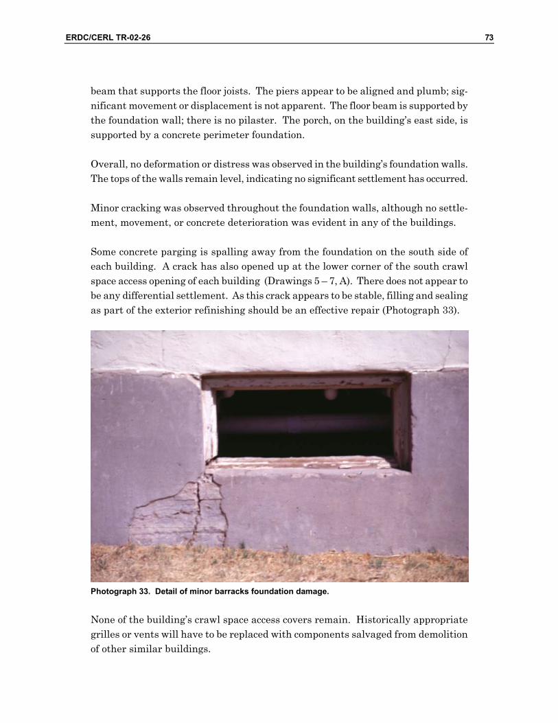
ERDC/CERL TR-02-26 73
beam that supports the floor joists. The piers appear to be aligned and plumb; sig-nificant movement or displacement is not apparent. The floor beam is supported by the foundation wall; there is no pilaster. The porch, on the building’s east side, is supported by a concrete perimeter foundation.
Overall, no deformation or distress was observed in the building’s foundation walls. The tops of the walls remain level, indicating no significant settlement has occurred.
Minor cracking was observed throughout the foundation walls, although no settle-ment, movement, or concrete deterioration was evident in any of the buildings.
Some concrete parging is spalling away from the foundation on the south side of each building. A crack has also opened up at the lower corner of the south crawl space access opening of each building (Drawings 5 – 7, A). There does not appear to be any differential settlement. As this crack appears to be stable, filling and sealing as part of the exterior refinishing should be an effective repair (Photograph 33).
Photograph 33. Detail of minor barracks foundation damage.
None of the building’s crawl space access covers remain. Historically appropriate grilles or vents will have to be replaced with components salvaged from demolition of other similar buildings.

74 ERDC/CERL TR-02-26
66..22..11..22 Firestopping
There are no fire barriers in the crawl spaces. Fire Marshall personnel indicated that installing sprinklers in the crawlspace would be an acceptable alternative to fire barriers, if fire barriers were required for the future occupancy type.
6.2.2 Superstructure
Structural components were examined at all locations of each building. Where framing members were concealed, floor or wall assemblies were examined for signs of distress. Any occurrence of cracking, deformation, deflection in either horizontal or vertical plane, differential settlement, lateral displacement, and other signs of distress in any load-bearing components were noted, as described in the following paragraphs.
6.2.3 Floor Construction
6.2.3.1 First Floor
The first floors did not exhibit any signs of extraordinary bounce or deflection when walking, bouncing, or jumping at any location in any of the three barracks build-ings. The floor systems are as rigid and sound as can be expected for buildings of wood frame construction and their age.
Overall, the first floors remains reasonably level. Some minor deflection or sagging was evident at several locations. As expected, sagging typically occurs at the joists’ midspan. However, there are generally no surface irregularities that would com-promise a rehabilitation or reuse design for these buildings.
Penetrations for plumbing and steam lines occur throughout the first floor. These penetrations must be sealed with the appropriate fire-stopping material.
Two washrooms are located at the north end of the building. The west-side wash-room was originally designed as a shower and latrine facility. The east-side room was originally an NCO room, which has been converted to a washroom. The origi-nal washroom floor, on the west side, has a concrete topping. The original design depicts floor-mounted urinals in this northeast corner of this room. The floor has settled noticeably in Buildings 7158 and 7159. The low point in each of these build-ings is at the north end of the partition dividing the washrooms (Drawings 5 – 7, B).

ERDC/CERL TR-02-26 75
It was reported that the sanitary sewer servicing the barracks buildings is ob-structed, and that the toilets and showers back up and overflow. Water damage is evident in all three barracks buildings. As part of a rehabilitation or reuse design, the floor framing in this area should be checked for potential deterioration due to water damage.
Original drawings depict a framed floor for the porch. The wooden floor has been replaced with concrete slab on all three buildings. The porch columns bear on the concrete slab at the porch’s first floor. Significant cracking has occurred in each building at the exterior corners of the floor slab, at the corner columns of the porch (Drawings 5 – 7, C; Photograph 34). As a result, the corner is breaking away from the slab. No such cracking is evident at the other columns.
Photograph 34. Detail of barracks porch slab cracks.
66..22..33..22 Second Floor
The second floors are supported by one row of 8-in. by 8-in. columns at the center of the building. The columns have been incorporated into the first floor partitions, and are only partially exposed in most cases. However, there is no evidence of deflec-tion, displacement, or distress in columns or partitions in any of the barracks build-ings.
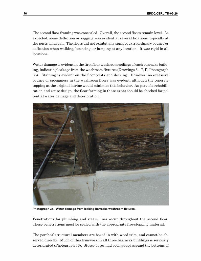
76 ERDC/CERL TR-02-26
The second floor framing was concealed. Overall, the second floors remain level. As expected, some deflection or sagging was evident at several locations, typically at the joists’ midspan. The floors did not exhibit any signs of extraordinary bounce or deflection when walking, bouncing, or jumping at any location. It was rigid in all locations.
Water damage is evident in the first floor washroom ceilings of each barracks build-ing, indicating leakage from the washroom fixtures (Drawings 5 – 7, D; Photograph 35). Staining is evident on the floor joists and decking. However, no excessive bounce or sponginess in the washroom floors was evident, although the concrete topping at the original latrine would minimize this behavior. As part of a rehabili-tation and reuse design, the floor framing in these areas should be checked for po-tential water damage and deterioration.
Photograph 35. Water damage from leaking barracks washroom fixtures.
Penetrations for plumbing and steam lines occur throughout the second floor. These penetrations must be sealed with the appropriate fire-stopping material.
The porches’ structural members are boxed in with wood trim, and cannot be ob-served directly. Much of this trimwork in all three barracks buildings is seriously deteriorated (Photograph 36). Stucco bases had been added around the bottoms of

ERDC/CERL TR-02-26 77
columns. This detail was not flashed or sealed, and water penetration and damage is evident (Photograph 37). Also, the stucco and wood trim enclosing the column bases is seriously deteriorated in many places. While the loadbearing members of the column assembly could not be observed, deterioration may have occurred in these components as well. DOE personnel recently observed the demolition of a similar porch, and reported that no structural problems were encountered with that building. However, it is recommended that the structures supporting the porches’ second floor decks and roofs be thoroughly evaluated as part of a rehabilitation or reuse design.
Photograph 36. Typical deteriorated wood trim on second-story barracks porches.

78 ERDC/CERL TR-02-26
Photograph 37. Water-damaged stucco detail on barracks porch column.
The porch’s second floor deck framing is exposed from below. Beam and joist con-nections appeared intact in all three barracks buildings. No distress was evident at floor framing connections and no significant bounce or deflection was observed when walking, jumping, or bouncing on any of the porch floors. The porch decking seemed to be intact (as observed from below) in all three barracks buildings, although split-ting is evident at the decking boards’ ends.
6.2.3.3 Stair Construction
The porch stairs are the only means of egress for the second floors. They are ex-posed wood and may not be acceptable under NFPA 101 for new construction. How-ever, Fire Marshall personnel indicated that as long as each entry is to the exterior, and there are two means of egress, these stairs would be acceptable for quarters-type occupancy.
Some splitting is evident at the bases of columns supporting the stair structures. The bottom ends of several stair stringers are split as well. No excessive deflection,
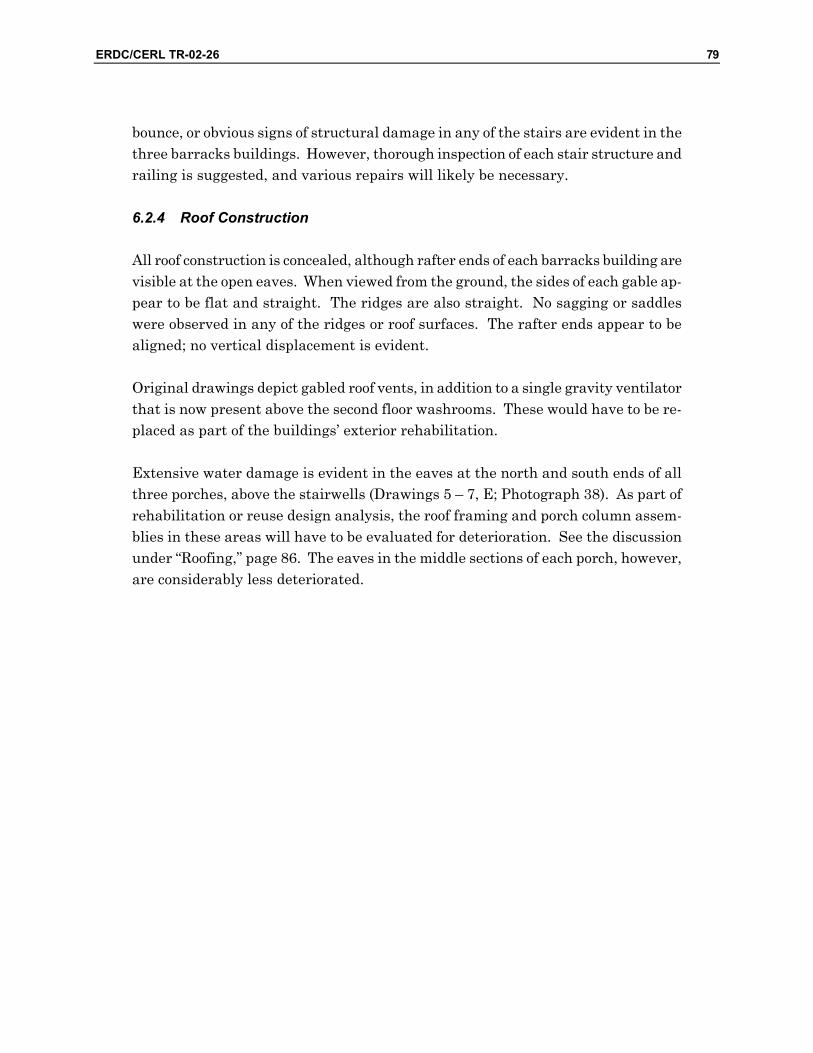
ERDC/CERL TR-02-26 79
bounce, or obvious signs of structural damage in any of the stairs are evident in the three barracks buildings. However, thorough inspection of each stair structure and railing is suggested, and various repairs will likely be necessary.
6.2.4 Roof Construction
All roof construction is concealed, although rafter ends of each barracks building are visible at the open eaves. When viewed from the ground, the sides of each gable ap-pear to be flat and straight. The ridges are also straight. No sagging or saddles were observed in any of the ridges or roof surfaces. The rafter ends appear to be aligned; no vertical displacement is evident.
Original drawings depict gabled roof vents, in addition to a single gravity ventilator that is now present above the second floor washrooms. These would have to be re-placed as part of the buildings’ exterior rehabilitation.
Extensive water damage is evident in the eaves at the north and south ends of all three porches, above the stairwells (Drawings 5 – 7, E; Photograph 38). As part of rehabilitation or reuse design analysis, the roof framing and porch column assem-blies in these areas will have to be evaluated for deterioration. See the discussion under “Roofing,” page 86. The eaves in the middle sections of each porch, however, are considerably less deteriorated.

80 ERDC/CERL TR-02-26
Photograph 38. Typical water damage to barracks porch roof.
The original design indicates a “fire stop” in the attic space midway in the buildings’ lengths. However, this was not accessible for observation in any of the three build-ings. As there is no load-bearing wall or structure below this “fire stop,” it is as-sumed to be a framed wall with some plaster or non-combustible surface. It is doubtful that this construction would comply with a contemporary definition of fire resistive. The Fire Marshall indicated that a fire sprinkler system can be installed in the attic space in lieu of constructing fire barriers, if required for the future occu-pancy.
6.3 Exterior Enclosure
All exterior components were observed. Any occurrences of cracking, deformation, leakage, weathering, material deterioration, and other signs of distress in any wall or roof components were noted, and are described as follows.
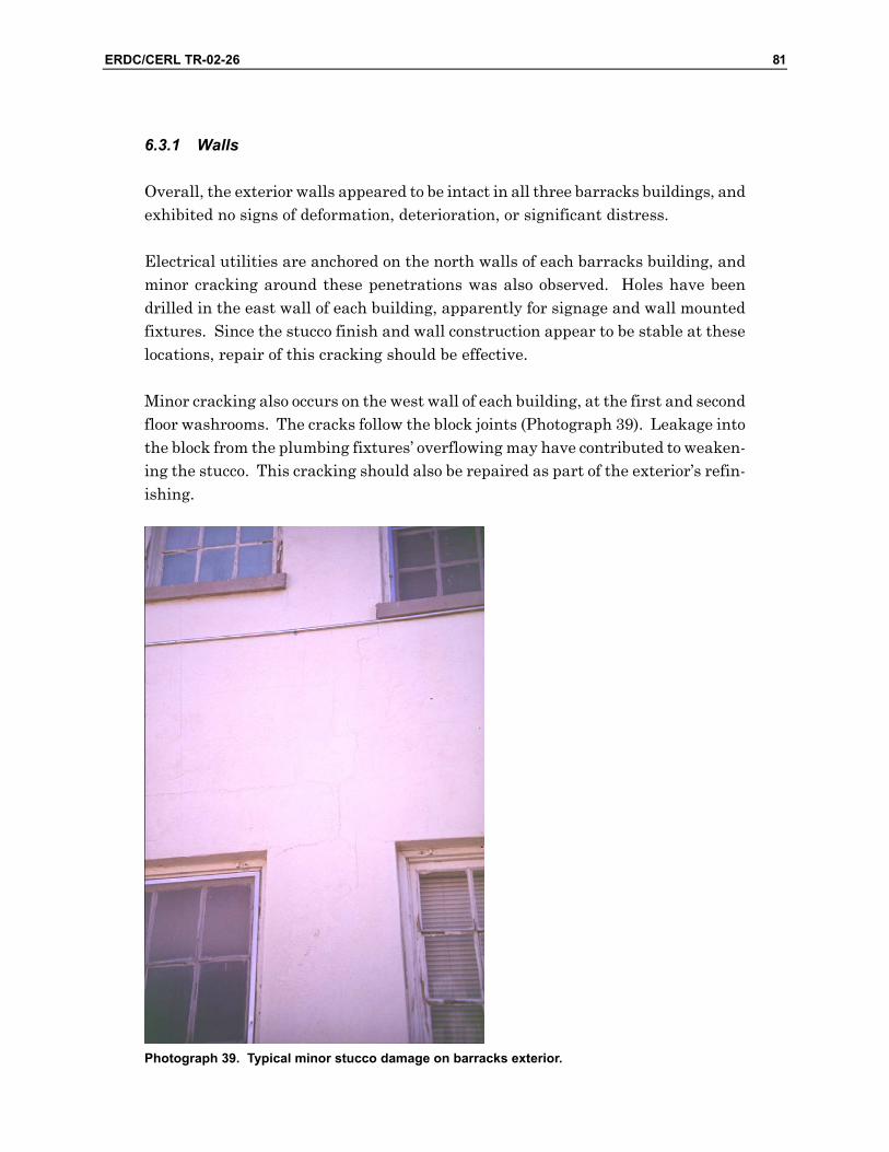
ERDC/CERL TR-02-26 81
6.3.1 Walls
Overall, the exterior walls appeared to be intact in all three barracks buildings, and exhibited no signs of deformation, deterioration, or significant distress.
Electrical utilities are anchored on the north walls of each barracks building, and minor cracking around these penetrations was also observed. Holes have been drilled in the east wall of each building, apparently for signage and wall mounted fixtures. Since the stucco finish and wall construction appear to be stable at these locations, repair of this cracking should be effective.
Minor cracking also occurs on the west wall of each building, at the first and second floor washrooms. The cracks follow the block joints (Photograph 39). Leakage into the block from the plumbing fixtures’ overflowing may have contributed to weaken-ing the stucco. This cracking should also be repaired as part of the exterior’s refin-ishing.
Photograph 39. Typical minor stucco damage on barracks exterior.

82 ERDC/CERL TR-02-26
The exterior trim enclosing the porches’ structural members is seriously deterio-rated, especially at the stairwells at the north and south ends of the building (Draw-ings 5 – 7, F; Photograph 40). Painting has apparently been neglected for some time. Many, if not most, of the trim boards are severely split and warped. Many baluster pieces are missing. While some of the original trim may be repairable, ex-tensive replacement probably will be necessary. The stucco “base” detail should be replaced to restore the original detail and prevent water accumulation.
Photograph 40. Typical deteriorated exterior trim on barracks.
Several elements of the original porch design have been modified throughout the buildings’ lives. For example, the porches’ second floors have been enclosed in Buildings 7157 and 7158 (Photograph 41). Also, the balusters on the porch’s first floor and stairs were replaced by steel pipe rails. These features should be restored to the original configuration as part of the buildings’ adaptive reuse. Components salvaged from previously demolished buildings may be applicable.

ERDC/CERL TR-02-26 83
Photograph 41. Non-historic second-story barracks porch enclosure.
6.3.2 Windows and Doors
The windows remain generally intact and operable, although their condition varies considerably. As part of an exterior restoration, minor repairs, replacement of glaz-ing compound, scraping, priming, and painting will be required as a minimum.
The most serious damage occurs on the west walls where several windows in each building will require some extensive repair (Photograph 42). For instance, most mullions dividing the first floor double windows are split at the bottoms. In addi-tion, several mullions are deteriorated to the point that some original components may have to be replaced rather than repaired. Several bottom sash rails are seri-ously deteriorated. Second floor windows on the east side generally have suffered less deterioration.

84 ERDC/CERL TR-02-26
Photograph 42. Seriously deteriorated barracks windows.
The upper sashes of the four north windows (at the washrooms) were replaced by vent hoods in all three buildings (Drawings 5 – 7, G; Photograph 43). These sashes will have to be replaced; salvaged components may be applicable.
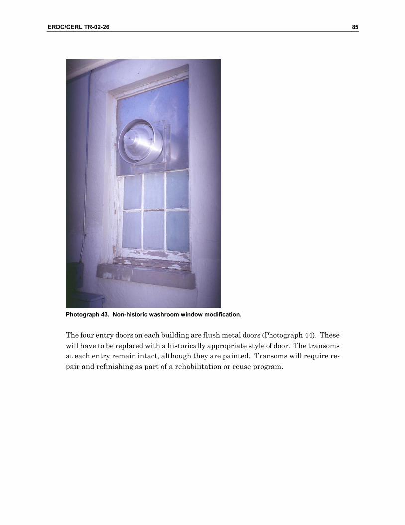
ERDC/CERL TR-02-26 85
Photograph 43. Non-historic washroom window modification.
The four entry doors on each building are flush metal doors (Photograph 44). These will have to be replaced with a historically appropriate style of door. The transoms at each entry remain intact, although they are painted. Transoms will require re-pair and refinishing as part of a rehabilitation or reuse program.

86 ERDC/CERL TR-02-26
Photograph 44. Non-historic barracks replacement door.
Egress requirements will be determined by the building’s future occupancy. Fire Marshall personnel indicate the two existing doorways on each floor are satisfactory for quarters-types of facilities. If other occupancies are considered, additional exits may be required, and will have to be a historically appropriate style of door.
66..33..33 Roofing
The roofing on each barracks building is light gray “t-lock” or “lock-tab” style as-phalt shingle. In general, the roofing appears to be fairly new and in generally good condition. No curling, gaps, fish-mouths, or missing shingles were observed. One gravity ventilator penetrates the roof at the ridge on the north end of each building. The ceilings below these vents did not exhibit signs of leakage, although leakage could have migrated elsewhere within the roof structure, such as to the eaves. The attic space was inaccessible for direct observation.
Other roof vents are portrayed in the original design, three on each side of the build-ing and two vents at the hip ends. A roof scuttle was also located on the west side of

ERDC/CERL TR-02-26 87
the roof. However, these features have since been removed from each building, and the openings have been closed and roofed over.
The roofing on each porch has the same style of asphalt shingle. However, the slope of the porch roof is only approximately 1:12, as opposed to approximately 4:12 for the main roofs. Shingle roofing is inappropriate for a roof of such low slope. It is likely that this type of roofing contributed to water intrusion and damage to the porchs’ roof, trim, and structure.
The original design depicts asbestos shingle roofing for the buildings and metal roof-ing for the porches. While asbestos shingles will not be used in a rehabilitation pro-ject, another shingle type may be historically more appropriate. For instance, a wide variety of metal roofing systems would be available for the porch roofs.
6.4 Interior Construction
It is assumed that non-original interior construction will be expendable during a rehabilitation or reuse. Therefore, only a cursory observation was performed to identify any potential problems that might undermine repairs, construction, and refinishing.
66..44..11 Partition Construction
At present, both the first and second floors of each building are partitioned into separate rooms. Both plaster and gypsum wallboard surfaces are present, suggest-ing the current space division has evolved over some period of time. In general, the partitioning in each of the three buildings, both original and added, appears to be sound.
6.4.2 Finishes
Plaster damage has occurred on the washroom partitions of each building. The plaster damage is visible on the partition dividing the washrooms and the lateral partition at the south side of the washrooms. This damage is presumably caused by water leakage and overflow from plumbing fixtures above. These are original parti-tions. Extensive finish repair will be required as part of an adaptive design. There does not, however, appear to be any severe deformation in the partition construction itself.

88 ERDC/CERL TR-02-26
The interior surfaces of the exterior walls appear to be generally sound and intact. Overall, little cracking or surface distress was observed. Minor repairs to the plas-ter surface will be necessary where fixtures, conduit, and other surface mounted at-tachments will be removed.
The first floor washroom ceilings are damaged from water leakage or overflow from plumbing fixtures above (Drawings 5 – 7, H; Photograph 45). The original plaster ceilings and the suspended ceiling systems added at a later date are both damaged. Plaster damage is more severe at the north end of the partition dividing the wash-rooms. Extensive repair will be required as part of a rehabilitation or reuse design.
Photograph 45. Typical water-damaged barracks ceiling in first-floor washroom.
The porches’ roof structures are enclosed with wood bead board ceilings. Deteriora-tion has occurred over the stairs at the north and south ends of each porch, where water damage to the roofs is most evident (Drawings 5 – 7, I; Photograph 46). Re-pair and refinishing may be possible, but replacement of some boards is likely to be required. Otherwise, the bead board ceilings appear to be reasonably sound, and rehabilitation may require only scraping, priming, and painting.

ERDC/CERL TR-02-26 89
Photograph 46. Typical barracks porch roof damage.
It is assumed that floor finishes will be replaced as part of a rehabilitation or reuse design. Specific conditions were not recorded. Sheet vinyl flooring was installed in the washrooms and is peeling because of water leakage, typically at the north end of the rooms.
The original interior doors have been replaced with flush wood doors. These would have to be replaced with historically appropriate interior doors as part of a rehabili-tation or reuse program. The original design depicts four-panel doors. Frames at the original door openings will require refinishing, but otherwise are intact.
66..55 Services
As part of a rehabilitation or reuse design, the plumbing, HVAC, and electrical sys-tems will typically require extensive upgrade. Therefore, a detailed assessment was not performed on these systems.
90 ERDC/CERL TR-02-26
6.5.1 Plumbing
The water supply is currently active in each barracks building. DPWL personnel report that the water supply lines are original. However, since they have not been used regularly in many months, sanitizing the water supply system as part of the rehabilitation and reuse design is suggested.
The sanitary sewer collection system will have to be cleared as part of a rehabilita-tion or reuse program.
The buildings’ original design depicts one washroom on each floor, containing five toilets and urinals, five lavatories and sinks, and a two-head shower stall with a single drain. Additional fixtures have been added to the adjacent room to accom-modate female occupants. The number of plumbing fixtures required for an adap-tive use will depend on the building’s occupancy. A sufficient fixture count and ca-pacity should be available for occupancies up to well over 100 people.
Plumbing fixtures are contemporary and were reported by DPWL personnel to be operable. Random operation of several fixtures indicated they are still serviceable. Whether they are appropriate for reuse will depend on future occupancy.
A gas-fired water heater and 250-gallon hot water storage tank that were installed in 1994 are located in a small enclosure at the north end of Building 7159 (Drawing 7, J). This water heating equipment serves all three barracks buildings. The ade-quacy of this size tank will have to be considered in a rehabilitation or reuse design, and it will probably depend on the occupancy and domestic hot water demand.
6.5.2 Fire Suppression
Sprinklers have been installed in Buildings 7157 and 7159. Fire Marshall person-nel indicate the distribution equipment is in working order. Sprinkler heads are compatible with the other sprinkler hardware at Fort Bliss, and appear to be in good working order.
The future occupancy of the buildings will dictate if and where sprinklers will be required. Fire Marshall personnel indicate installing sprinklers in attics and crawl spaces will be satisfactory in lieu of constructing fire barriers, where fire barriers would ordinarily be required. They also recommend installing sprinklers in other occupied spaces at a distribution of one sprinkler head per roughly every 240 sq ft.
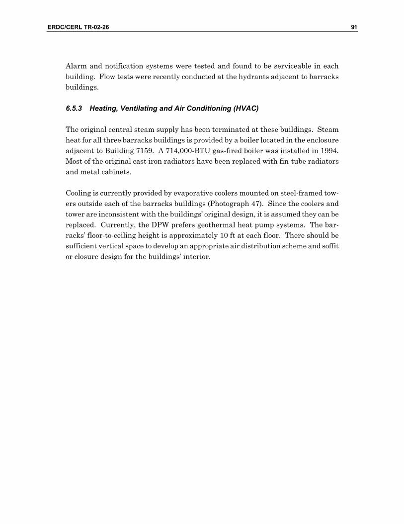
ERDC/CERL TR-02-26 91
Alarm and notification systems were tested and found to be serviceable in each building. Flow tests were recently conducted at the hydrants adjacent to barracks buildings.
6.5.3 Heating, Ventilating and Air Conditioning (HVAC)
The original central steam supply has been terminated at these buildings. Steam heat for all three barracks buildings is provided by a boiler located in the enclosure adjacent to Building 7159. A 714,000-BTU gas-fired boiler was installed in 1994. Most of the original cast iron radiators have been replaced with fin-tube radiators and metal cabinets.
Cooling is currently provided by evaporative coolers mounted on steel-framed tow-ers outside each of the barracks buildings (Photograph 47). Since the coolers and tower are inconsistent with the buildings’ original design, it is assumed they can be replaced. Currently, the DPW prefers geothermal heat pump systems. The bar-racks’ floor-to-ceiling height is approximately 10 ft at each floor. There should be sufficient vertical space to develop an appropriate air distribution scheme and soffit or closure design for the buildings’ interior.
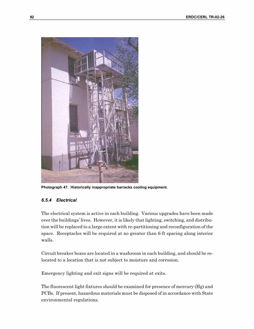
92 ERDC/CERL TR-02-26
Photograph 47. Historically inappropriate barracks cooling equipment.
6.5.4 Electrical
The electrical system is active in each building. Various upgrades have been made over the buildings’ lives. However, it is likely that lighting, switching, and distribu-tion will be replaced to a large extent with re-partitioning and reconfiguration of the space. Receptacles will be required at no greater than 6-ft spacing along interior walls.
Circuit breaker boxes are located in a washroom in each building, and should be re-located to a location that is not subject to moisture and corrosion.
Emergency lighting and exit signs will be required at exits.
The fluorescent light fixtures should be examined for presence of mercury (Hg) and PCBs. If present, hazardous materials must be disposed of in accordance with State environmental regulations.

ERDC/CERL TR-02-26 93
There should be sufficient vertical space to develop an appropriate troffer or soffit detail for ambient lighting, power distribution, and cabling throughout the building.
6.6 Sitework
Sitework is generally considered in this assessment only within the buildings’ five-foot lines. However, the following should be noted relative to the building’s condi-tion and performance.
The site slopes northwest to southeast, with an elevation difference of 2 ft or more from the north end of a building to the south. The grade slopes into each building at the north end, has built up above the top of the foundation (Drawings 5 – 7, K), and is closing the crawl space access portals on the west side. Water intrusion from runoff does not appear to be a problem. However, regrading to ensure positive drainage away from the buildings on all sides should be included as part of the re-habilitation and reuse design.
The sanitary sewer from the barracks buildings is reported to be broken or clogged. Recent troop occupancy has resulted in sanitary fixtures and showers backing up and overflowing into the buildings. Water damage is evident, as described above. The sanitary drainage from these buildings must be cleared and/or repaired as part of the rehabilitation design.
6.7 Building-Specific Observations
6.7.1 Building 7157
6.7.1.1 Substructure
A shallow basement is located under the porch. Access to the basement is via a stairwell on the porch’s north end. There were no atypical conditions observed in this basement or the remainder of the building’s foundation systems.
6.7.1.2 Superstructure
There is a low spot in the first floor, in the northwest corner of room 107 (Drawing 5, L). Plumbing fixture rough-ins are located on the north wall of this room, and the floor appears to have suffered water damage. The floor framing and sheathing at this location should be evaluated as part of a reuse design. The crawl space in

94 ERDC/CERL TR-02-26
Building 7157 was too narrow to permit access and visual observation at this loca-tion. However, in the same location in Building 7159, several joists had been notched at the bottom (tension) edge for an electrical conduit. It is possible a simi-lar modification may have taken place in all three barracks buildings.
Drawing 5. Building 7157 key plan.
The top edges of the floor beam, which carry the joists, were observed to be deterio-rated and crushed under the washrooms at the north end of the building. While se-rious settlement was not obvious from the washroom floor above, the condition of the beam and joists should be evaluated. Repair and realigning of some framing members will likely be necessary.
A vertical crack appears at the northwest corner of room 208, which is directly above room 107. This suggests that settlement from the floor below may have pulled this partition with it.

ERDC/CERL TR-02-26 95
The second floors are supported by one row of 8-in. by 8-in. columns at the center of the building. The second floor columns remain free standing in room 103, but have been incorporated into the partitions in rooms 104, 105, and 106. There is no evi-dence of deflection, displacement, or distress in the columns or partitions.
6.7.1.3 Exterior Closure
Some stucco is spalling around pipes near the grade at the north end of the west wall.
Cracking has occurred on the west wall, emanating from the bottom corners of a first floor window at the south end of the building (Drawing 5, M). No vertical dis-placement or differential settling is evident, but this crack is more prominent than the simple stair-step cracking occurring elsewhere in the buildings’ walls. It ex-tends from the wall downward into the foundation. However, as this crack appears to be stable, repair and sealing should remain effective as long as the stucco itself remains intact.
An evaporative cooling unit is mounted on a steel tower at the south end of the building (Drawing 5, N). Ductwork enters the second floor through the wall. If the cooling unit will be removed, the opening in the wall will have to be filled and fin-ished to match the existing stucco.
The second floor of the porch has been enclosed. The columns and trim remain in-place, but the baluster has been replaced with a framed wall and windows. This enclosure will have to be removed and the balusters replaced as part of the exterior restoration. Components salvaged from previously demolished buildings may be applicable.
Roof leakage is evident throughout the enclosed porch. Water stains appear on the walls at the north and south ends of the porch (Photograph 48). Ceiling-mounted light fixtures show signs of having been filled with water.

96 ERDC/CERL TR-02-26
Photograph 48. Signs of roof leakage in porch of Building 7157.
A window sash has been removed to allow entry of a duct from an evaporative cooler to Room 105 (Drawing 5, O). This sash will have to be replaced; a unit salvaged from the demolition of other similar buildings should be appropriate.
Where the porch is enclosed, the exterior windows at the second floor east wall have been removed. The openings have been filled with metal stud framing and gypsum wallboard. The windows enclosing the porch are not the same dimension as the windows removed from the wall, so historically appropriate replacements salvaged from the demolition of other similar buildings will be appropriate.
6.7.1.4 Interior Construction
Room 101 was enlarged by removing the original partition and building a new parti-tion several feet to the north.
The original design does not show any plumbing in rooms 101, 102, 201, or 202. However, a partial-height plumbing chase has been added to the west wall dividing rooms 101 and 201 (Drawing 5, P; Photograph 49). The rough-ins are still in place. Electrical conduit has also been surface mounted. These items should be removed as part of a rehabilitation design, and the plaster finishes should be repaired.
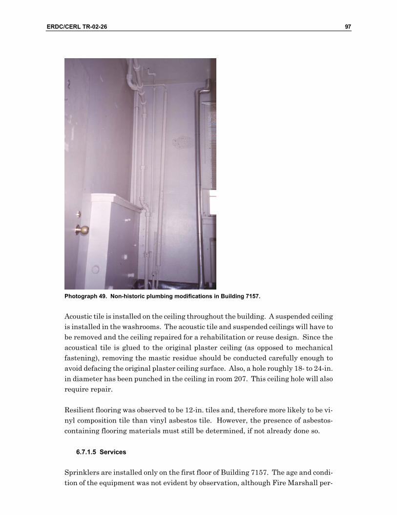
ERDC/CERL TR-02-26 97
Photograph 49. Non-historic plumbing modifications in Building 7157.
Acoustic tile is installed on the ceiling throughout the building. A suspended ceiling is installed in the washrooms. The acoustic tile and suspended ceilings will have to be removed and the ceiling repaired for a rehabilitation or reuse design. Since the acoustical tile is glued to the original plaster ceiling (as opposed to mechanical fastening), removing the mastic residue should be conducted carefully enough to avoid defacing the original plaster ceiling surface. Also, a hole roughly 18- to 24-in. in diameter has been punched in the ceiling in room 207. This ceiling hole will also require repair.
Resilient flooring was observed to be 12-in. tiles and, therefore more likely to be vi-nyl composition tile than vinyl asbestos tile. However, the presence of asbestos-containing flooring materials must still be determined, if not already done so.
6.7.1.5 Services
Sprinklers are installed only on the first floor of Building 7157. The age and condi-tion of the equipment was not evident by observation, although Fire Marshall per-

98 ERDC/CERL TR-02-26
sonnel indicate it is serviceable. Sprinkler heads are reported to be serviceable as well.
If sprinklers are required for a rehabilitation or reuse design, the adequacy of the existing equipment for extension to the attic, second floor, and crawl space must be verified.
On the building’s west side, the radiators are located under each window. On the building’s east side, the radiators have been moved into the enclosed porch. The supply and return lines, however, remain accessible, and will have to be relocated to the building’s interior when the porches are reopened.
The first floor is serviced by an evaporative cooler located at grade level outside of room 105. A duct enters the room through one window’s upper sash, which tees into the supply duct running the length of the building and supplying each room. The second floor is serviced by a cooler mounted on a steel-framed tower at the south end of the building outside of room 202. A duct enters the room through the wall and runs the length of the building, supplying each room. The coolers were in-stalled 5 years ago and are reported by DPW personnel to be serviceable (Photograph 50).
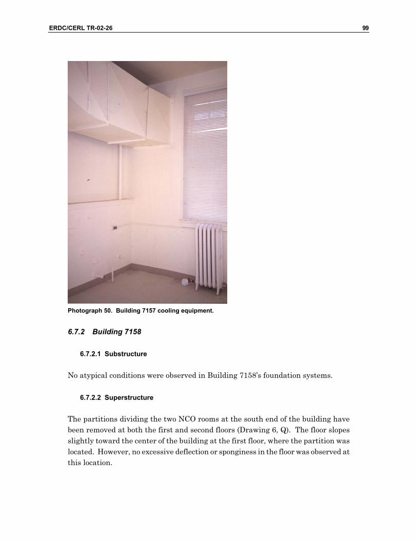
ERDC/CERL TR-02-26 99
Photograph 50. Building 7157 cooling equipment.
6.7.2 Building 7158
6.7.2.1 Substructure
No atypical conditions were observed in Building 7158’s foundation systems.
6.7.2.2 Superstructure
The partitions dividing the two NCO rooms at the south end of the building have been removed at both the first and second floors (Drawing 6, Q). The floor slopes slightly toward the center of the building at the first floor, where the partition was located. However, no excessive deflection or sponginess in the floor was observed at this location.

100 ERDC/CERL TR-02-26
Drawing 6. Building 7158 key plan.
Similar to Building 7157, there is a low spot in the first floor, in the northwest cor-ner of room 106 (Drawing 6, R). Leakage and water damage is apparent by the buckling in the underlayment. While no other sponginess, deflection, or distress was evident, evaluating the floor framing and subfloor at this location is recom-mended as part of a reuse design. Several joists had been notched at the bottom (tension) edge for an electrical conduit in the same location in Building 7159. It is possible a similar modification may have also been made in Building 7157 and 7158 as well.
A large area of the plaster ceiling at the east first floor washroom has been removed or has fallen (Drawing 6, S). Water damage to the joists and floor sheathing is evi-dent when viewed from below. Framing and sheathing should be examined as part of the rehabilitation and reuse design analysis.
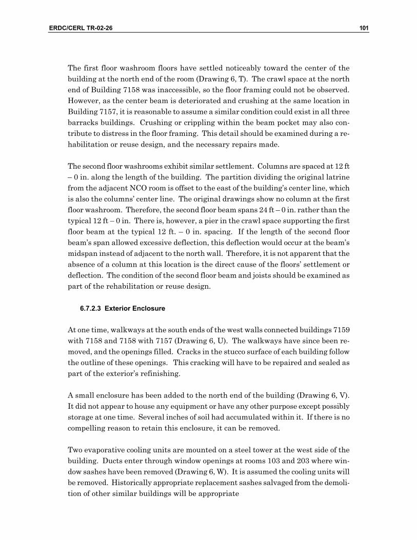
ERDC/CERL TR-02-26 101
The first floor washroom floors have settled noticeably toward the center of the building at the north end of the room (Drawing 6, T). The crawl space at the north end of Building 7158 was inaccessible, so the floor framing could not be observed. However, as the center beam is deteriorated and crushing at the same location in Building 7157, it is reasonable to assume a similar condition could exist in all three barracks buildings. Crushing or crippling within the beam pocket may also con-tribute to distress in the floor framing. This detail should be examined during a re-habilitation or reuse design, and the necessary repairs made.
The second floor washrooms exhibit similar settlement. Columns are spaced at 12 ft – 0 in. along the length of the building. The partition dividing the original latrine from the adjacent NCO room is offset to the east of the building’s center line, which is also the columns’ center line. The original drawings show no column at the first floor washroom. Therefore, the second floor beam spans 24 ft – 0 in. rather than the typical 12 ft – 0 in. There is, however, a pier in the crawl space supporting the first floor beam at the typical 12 ft. – 0 in. spacing. If the length of the second floor beam’s span allowed excessive deflection, this deflection would occur at the beam’s midspan instead of adjacent to the north wall. Therefore, it is not apparent that the absence of a column at this location is the direct cause of the floors’ settlement or deflection. The condition of the second floor beam and joists should be examined as part of the rehabilitation or reuse design.
6.7.2.3 Exterior Enclosure
At one time, walkways at the south ends of the west walls connected buildings 7159 with 7158 and 7158 with 7157 (Drawing 6, U). The walkways have since been re-moved, and the openings filled. Cracks in the stucco surface of each building follow the outline of these openings. This cracking will have to be repaired and sealed as part of the exterior’s refinishing.
A small enclosure has been added to the north end of the building (Drawing 6, V). It did not appear to house any equipment or have any other purpose except possibly storage at one time. Several inches of soil had accumulated within it. If there is no compelling reason to retain this enclosure, it can be removed.
Two evaporative cooling units are mounted on a steel tower at the west side of the building. Ducts enter through window openings at rooms 103 and 203 where win-dow sashes have been removed (Drawing 6, W). It is assumed the cooling units will be removed. Historically appropriate replacement sashes salvaged from the demoli-tion of other similar buildings will be appropriate

102 ERDC/CERL TR-02-26
Other window panes have been broken. Pigeons have occupied several rooms and pigeon excrement will have to be cleaned.
The second floor of the porch has been enclosed. The columns and trim remain in-place, but the baluster has been replaced with a wall and windows. This enclosure will have to be removed as part of a rehabilitation or reuse design. The original ex-terior windows within the enclosed space remain in place and operable.
An evaporative cooler is cantilevered from the north wall of the second floor porch enclosure (Drawing 6, X). The supply line is leaking and dripping water is accumu-lating on the porch deck. Furthermore, the framed wall onto which the cooler is hung is deflecting. It is assumed that this unit will be removed should the porch be rehabilitated to its original open configuration.
Roof leakage is evident throughout the enclosed porch. For example, the wall sur-faces are stained at the north end of the porch (Drawing 6, Y). Also, ceiling mounted light fixtures show signs of having been filled with water (Photograph 51).
Photograph 51. Signs of porch roof leakage in Building 7158.
/i
H 7 rl //A
1 ^^^/ " >■
fe 1 ll

ERDC/CERL TR-02-26 103
6.7.2.4 Interior Construction
Water leakage and overflow has damaged the plaster in the washroom partitions on both the first and second floors (Drawing 6, Z; Photograph 52). Water leakage has also damaged the vinyl flooring to the extent it is peeling off of the floor (Drawing 6, AA; Photograph 53). These items will require extensive repair.
Photograph 52. Signs of water damage in Building 7158 washrooms.

104 ERDC/CERL TR-02-26
Photograph 53. Damaged vinyl flooring in Building 7158 washrooms.
A crack has opened at the northwest corner of Rooms 106 and 206 (Drawing 6, BB). It is apparent that the floor settlement is pulling the partition away from the exte-rior wall. Once the floor deflection is stabilized, this crack should be repaired as part of the interior’s rehabilitation and should remain effective.
Pigeon contamination occurs throughout the building. It is heaviest where the evaporative cooling ducts enter the building on the west side.
Acoustical tile was adhered to the ceilings in Building 7158. Additional cleaning and surface repair will be required once the tiles are removed.
6.7.2.5 Fire Suppression
Building 7158 is not protected by a sprinkler system. The future occupancy of the buildings will dictate if and where sprinklers will be required. Fire Marshall per-sonnel indicate installing a sprinkler system in attics and crawl spaces will be satis-factory in lieu of constructing fire barriers, where barriers would ordinarily be re-quired. They also recommend installing sprinklers within other occupied spaces at a distribution of one sprinkler head per roughly every 240 sq ft.
^k
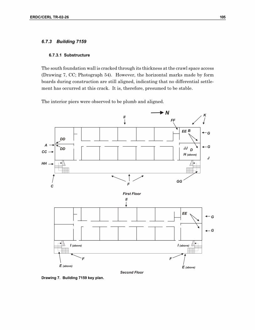
ERDC/CERL TR-02-26 105
6.7.3 Building 7159
6.7.3.1 Substructure
The south foundation wall is cracked through its thickness at the crawl space access (Drawing 7, CC; Photograph 54). However, the horizontal marks made by form boards during construction are still aligned, indicating that no differential settle-ment has occurred at this crack. It is, therefore, presumed to be stable.
The interior piers were observed to be plumb and aligned.
Drawing 7. Building 7159 key plan.
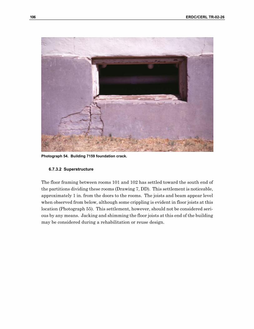
106 ERDC/CERL TR-02-26
Photograph 54. Building 7159 foundation crack.
6.7.3.2 Superstructure
The floor framing between rooms 101 and 102 has settled toward the south end of the partitions dividing these rooms (Drawing 7, DD). This settlement is noticeable, approximately 1 in. from the doors to the rooms. The joists and beam appear level when observed from below, although some crippling is evident in floor joists at this location (Photograph 55). This settlement, however, should not be considered seri-ous by any means. Jacking and shimming the floor joists at this end of the building may be considered during a rehabilitation or reuse design.
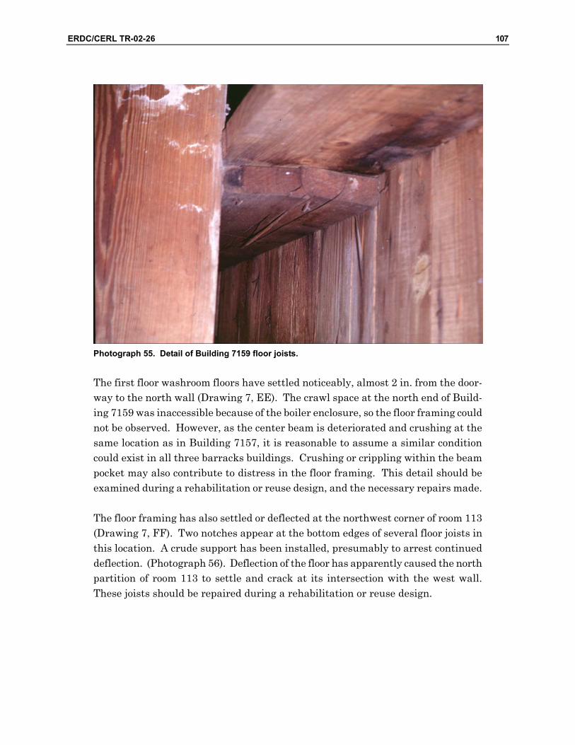
ERDC/CERL TR-02-26 107
Photograph 55. Detail of Building 7159 floor joists.
The first floor washroom floors have settled noticeably, almost 2 in. from the door-way to the north wall (Drawing 7, EE). The crawl space at the north end of Build-ing 7159 was inaccessible because of the boiler enclosure, so the floor framing could not be observed. However, as the center beam is deteriorated and crushing at the same location as in Building 7157, it is reasonable to assume a similar condition could exist in all three barracks buildings. Crushing or crippling within the beam pocket may also contribute to distress in the floor framing. This detail should be examined during a rehabilitation or reuse design, and the necessary repairs made.
The floor framing has also settled or deflected at the northwest corner of room 113 (Drawing 7, FF). Two notches appear at the bottom edges of several floor joists in this location. A crude support has been installed, presumably to arrest continued deflection. (Photograph 56). Deflection of the floor has apparently caused the north partition of room 113 to settle and crack at its intersection with the west wall. These joists should be repaired during a rehabilitation or reuse design.
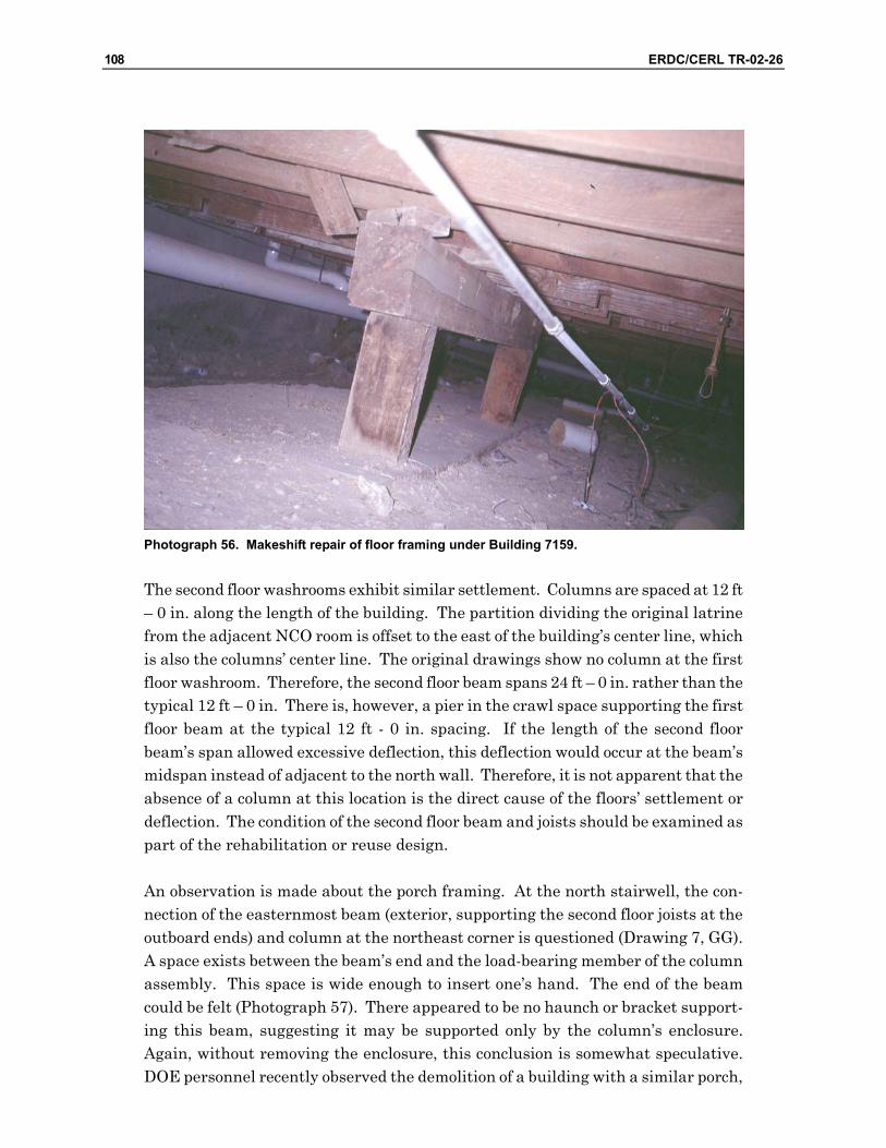
108 ERDC/CERL TR-02-26
Photograph 56. Makeshift repair of floor framing under Building 7159.
The second floor washrooms exhibit similar settlement. Columns are spaced at 12 ft – 0 in. along the length of the building. The partition dividing the original latrine from the adjacent NCO room is offset to the east of the building’s center line, which is also the columns’ center line. The original drawings show no column at the first floor washroom. Therefore, the second floor beam spans 24 ft – 0 in. rather than the typical 12 ft – 0 in. There is, however, a pier in the crawl space supporting the first floor beam at the typical 12 ft - 0 in. spacing. If the length of the second floor beam’s span allowed excessive deflection, this deflection would occur at the beam’s midspan instead of adjacent to the north wall. Therefore, it is not apparent that the absence of a column at this location is the direct cause of the floors’ settlement or deflection. The condition of the second floor beam and joists should be examined as part of the rehabilitation or reuse design.
An observation is made about the porch framing. At the north stairwell, the con-nection of the easternmost beam (exterior, supporting the second floor joists at the outboard ends) and column at the northeast corner is questioned (Drawing 7, GG). A space exists between the beam’s end and the load-bearing member of the column assembly. This space is wide enough to insert one’s hand. The end of the beam could be felt (Photograph 57). There appeared to be no haunch or bracket support-ing this beam, suggesting it may be supported only by the column’s enclosure. Again, without removing the enclosure, this conclusion is somewhat speculative. DOE personnel recently observed the demolition of a building with a similar porch,

ERDC/CERL TR-02-26 109
and no structural problems were evident in the porch’s construction. However, cau-tion should still be exercised when removing the column and beam enclosure to en-sure that load-carrying members are not supported by trim alone.
Photograph 57. Possible structural problem with barracks porch support beam.
6.7.3.3 Exterior Enclosure
The original design depicts two sets of stairs at the front of the porch from grade to the first floor. The south set has been moved to the south side of the porch (Drawing 7, HH; Photograph 58). In an adaptive use project, the porch stairs should be returned to their original location and detailing.

110 ERDC/CERL TR-02-26
Photograph 58. Non-historic modification of Building 7159 exterior stairways.
Two evaporative cooling units are mounted on a steel tower at the west side of the building. Ducts enter through window openings on the first and second floors where window sashes have been removed (Drawing 7, II; Photograph 59). It is assumed the cooling units will be removed. Once this is accomplished, the sashes will have to be replaced. Replacing these items with components that were salvaged from demo-lition of similar buildings would be appropriate.
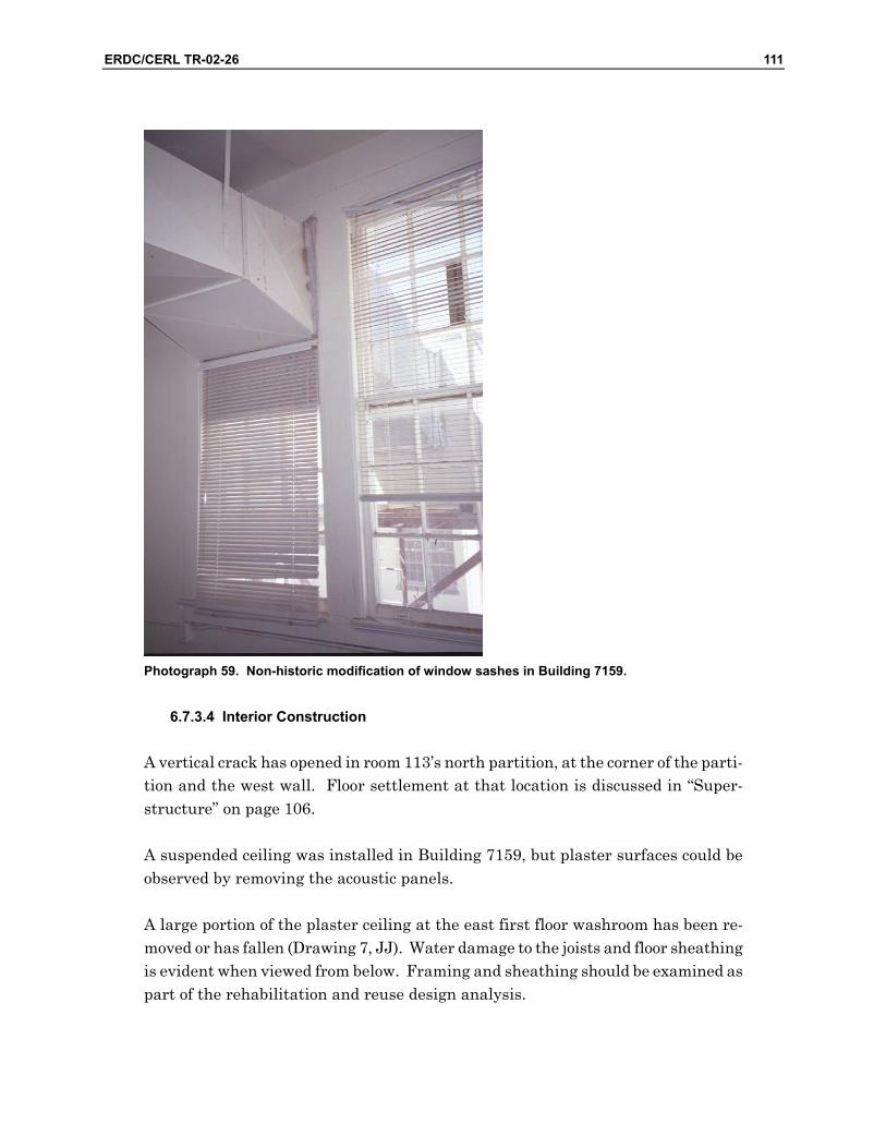
ERDC/CERL TR-02-26 111
Photograph 59. Non-historic modification of window sashes in Building 7159.
6.7.3.4 Interior Construction
A vertical crack has opened in room 113’s north partition, at the corner of the parti-tion and the west wall. Floor settlement at that location is discussed in “Super-structure” on page 106.
A suspended ceiling was installed in Building 7159, but plaster surfaces could be observed by removing the acoustic panels.
A large portion of the plaster ceiling at the east first floor washroom has been re-moved or has fallen (Drawing 7, JJ). Water damage to the joists and floor sheathing is evident when viewed from below. Framing and sheathing should be examined as part of the rehabilitation and reuse design analysis.

112 ERDC/CERL TR-02-26
6.7.4 Fire Suppression
A sprinkler system is installed in Building 7159. Fire Marshall personnel indicate that the sprinkler and alarm system is serviceable. Fire Marshall personnel also indicate installing sprinklers in attics and crawl spaces will be satisfactory in lieu of constructing fire barriers, where barriers would ordinarily be required. They also recommend spacing sprinkler heads within occupied spaces at a distribution of one sprinkler head per roughly every 240 sq ft.
Alarm systems were tested by Fire Marshall personnel and found to be serviceable.
6.8 Recommendations
All three barracks building are fundamentally sound. The structural systems ap-pear to be performing as intended, although further evaluation of some components is advised. The exterior closure systems are generally intact. The original interior construction is reasonably sound, with the exception of the water damage at the washrooms. Non-original partitioning can be removed. With the appropriate up-grades, repairs, and refinishing, the building should be completely serviceable.
The following tasks will be necessary for an adaptive use design. Adaptive use for housing and administrative functions is assumed. Most tasks are common and straightforward, and should be completed without great difficulty. Fire safety pro-visions (fire area separation, egress) may present a design challenge, although it should not be insurmountable.
• Seal the foundation cracks at the access scuttles. • Provide wheelchair access, as required for the occupancy. Accessibility ac-
commodations could be omitted on the justification that all occupants will be able-bodied persons. However this premise may be quite difficult to support. Wheelchair access must be provided to administrative buildings. It would also be advisable to design some number of first floor dwelling units to be handicapped accessible.
• Analyze the floor system’s design and capability to carry the live loads re-quired for their occupancy type. Verify the floor system’s sufficiency for the intended occupancy. ASCE-7, Minimum Design Loads for Buildings and Other Structures, requires the following: Office: 50 psf distributed live load, 2000 pounds concentrated load, 100 psf distributed live
load for lobbies and first floor corridors, and 80 psf for corridors above the first floor. Hotel/Motel: 50 psf

ERDC/CERL TR-02-26 113
Multifamily residential: 50 psf • There are some areas of concern regarding some structural components.
While there is no profound damage or failure evident, a more detailed exami-nation should be performed for each building at the following: Roof framing and sheathing at the porches, especially on the north and south ends. Porch framing, including stairs. First and second floor framing at the semi-private rooms (south ends of the buildings), at the
washrooms (north ends of the buildings), and at the other locations identified on pages 74,75,93,99, and 106.
Porch floor slabs at their southeast corners, where they are cracked under the porch columns. • Pending further evaluation, replacement of roof sheathing and possibly re-
pair or replacement of some rafters, may be necessary at the north and south ends of the porches.
• While no failure is evident, it would be advisable to rebuild the stairs for each building. Non combustible or fire resistive construction may be required, de-pending on the future occupancy and egress incorporated into the adaptive use design.
• Re-level the first floor framing at the semi-private rooms (south ends of the buildings), at the washrooms (north ends of the buildings), and at the other locations identified on pages 74, 75, 93, 99, and 106. Repair the notched and cut joists. Replace deteriorated sub-floor in the washrooms, and repair or re-place joists if necessary.
• Repair each concrete porch slab at the southeast corners. The nature of this repair will depend on further evaluation of the failure mode.
• Specific fire safety requirements will be dictated by occupancy type, features of the adaptive use design, and the constraints of existing construction. The following issues must be resolved during design development. Numbers and location of means of egress. Construction and protection of means of egress. Fire area separation. Firestopping in attics and crawl spaces. Sprinkler requirements.
• Remove the enclosure from the second floor balconies in Buildings 7157 and 7158. Restore or replace the appropriate column and baluster detailing.
• Remove gypsum wallboard and metal stud infill and reinstall the second floor east windows in Building 7157.
• Repair / replace and refinish the trim enclosing the porches’ structural mem-bers. Restore or replace the appropriate column and baluster detailing.
• Repair and refinish the windows. Replace sashes where they have been re-moved.

114 ERDC/CERL TR-02-26
• Replace the entry doors with a historically appropriate style of door. Repair and refinish the frames and transoms. Replace the door securing the “base-ment” under Building 7159’s porch.
• Reinstall the original roof vents and re-roof with a historically appropriate style of shingle. Use metal roofing for the porches.
• Remove the enclosure added to the north end of Building 7158. • Perform the necessary minor repairs to the buildings’ exteriors (stucco sur-
faces and trim), and refinish. • Repair and/or replace damaged plaster partitions and ceilings at the build-
ings’ washrooms. • Remove the plumbing chase from the former semi-private patient rooms on
the south ends of the buildings. • Remove the non-original partitions. Repair ceiling and interior finish at the
exterior walls, as necessary. The first floor interior space is interrupted only by one row of columns and the second floor interior space is open. Therefore, adaptive reuse designs can be developed for a wide variety of uses and spatial configurations.
• Replace the floor finishes as appropriate for the adaptive use design(s). Car-pet and resilient flooring are appropriate materials, as the wood-framed floor will deflect to some extent. Ceramic flooring should be installed only over a rigid cementitious underlayment board.
• Remove extraneous plumbing from the former semi-private patient rooms at the south ends of the buildings, and from the washrooms where not required by the adaptive reuse design.
• Relocate and replace plumbing fixtures according to the adaptive reuse de-sign. Accessibility of supply and drain-waste-vent systems from the crawl space should allow flexibility in a new plumbing plan. The open interior plan and potential for a variety of partitioning schemes should allow flexibility in fixture placement and riser location.
• Sanitize the water supply system. • Verify the viability of each building’s sprinkler system. • Upgrade the HVAC system in each building.
The existing steam distribution system should be adaptable to a variety of interior configura-tions. Provide for individual control of radiators within each enclosed space or housing unit.
Consider air conditioning in lieu of evaporative cooling. Package units can be located within the buildings’ interiors. Alternatively, external compressor/condenser units can be screened and/or integrated with external building features such as stair towers or wheel chair ramps.
Consider zoning the east and west spaces within the buildings separately with multizone air handling equipment or individual air conditioning equipment to address differential cool-
ERDC/CERL TR-02-26 115
ing loads resulting from building configuration and orientation. As the barracks buildings are long and narrow and oriented north-and-south, cooling loads can vary considerably within the building throughout the day.
• The electrical system will likely require substantial upgrading to meet pre-vailing standards and accommodate the future occupancy. Fluorescent fix-tures must be examined for mercury (Hg) and PCB content. If Hg and PCBs are present, fixtures must be disposed of according to State hazardous mate-rial regulations.
• Regrade around the buildings, especially at the buildings’ north and west sides, to ensure positive drainage away from the foundations and to prevent the build-up of soil over the tops of the foundation walls. Protect the grade adjacent to the buildings with planting, rock blanket, or other surface that will prevent erosion.
• The barracks buildings can be adapted to a variety of uses. Three design concepts will be developed by CERL as a follow-on to this condition assess-ment: Restore a building to its original configuration, upgrade it to contemporary use and standards,
and adapt it to an administrative occupancy. Develop a hotel/motel-type facility design. Basing such a design on the Army Standard De-
signs for Visiting Officers Quarters would be a reasonable point of departure. Develop an apartment-type design for families. Basing such a design on Army Family Hous-
ing (AFH) standards would be a reasonable point of departure.

116 ERDC/CERL TR-02-26
7 Building 7166: Bachelor Officers Quarters
7.1 Description
The Bachelor Officer’s Quarters (BOQ) was originally built as a library and was re-ported to have been modified for a variety of administrative functions. It is a one-story rectangular building and is currently 30.5 ft wide by 60.5 ft long, or 4392 sq ft in plan area. An addition to the north end of the building significantly increased its floor area. It has recently been converted to Bachelor Officer’s Quarters (BOQ).
The main entry is through a porch on the west side of the building. The south half of the building consists of a living room and kitchen. The north half of the building includes two sleeping rooms with bathrooms.
The foundation is reinforced concrete. The floor is framed with joists, whose orien-tation and span vary. The exterior walls are terra cotta tile masonry with a stucco exterior finish. The roof structure consists of wood rafters spanning the width of the building.
The interior of the former library is finished in painted plaster and gypsum wall-board. The floors are either carpeted or vinyl composition tile, with ceramic tile in-stalled at the main entry foyer. The ceilings are painted gypsum board.
An exterior photograph of Building 7166 is shown in Photograph 60.

ERDC/CERL TR-02-26 117
Photograph 60. Exterior photograph of Building 7166 (BOQ).
7.2 Condition Assessment
7.2.1 Substructure
7.2.1.1 Foundation Construction
Foundation walls were observed around the building’s perimeter from the exterior. Any occurrence of cracking, deformation, deflection in either horizontal or vertical plane, differential settlement, heaving, lateral displacement, leakage, concrete dete-rioration, exposed reinforcing, or other signs of distress were noted.
The foundation is visible around the building’s perimeter, with the exception of the west side. This condition is discussed under Sitework, on page 127. The top of the foundation wall is level, and there is generally no evidence of differential settlement or displacement.
The foundation for the north part of the building was accessible from the basement. No distress was observed.
A vertical crack occurs in the parging on the east side of the foundation, where an addition was constructed (Drawing 8,A; Photograph 61). The crack continues up

118 ERDC/CERL TR-02-26
into the wall. However, there is no evidence of differential settlement between these two areas of the building.
Drawing 8. Building 7166 key plan.

ERDC/CERL TR-02-26 119
Photograph 61. BOQ foundation and wall crack.
7.2.1.2 Slab on Grade
The basement slab on the north end of the building was observed to be in good con-dition. The basement at the south end of the building was inaccessible.
7.2.2 Superstructure
Structural components were examined in all locations of the building. Where fram-ing or load-bearing members were concealed, floor or wall assemblies were exam-ined for signs of distress. Any occurrence of cracking, deformation, deflection in ei-ther horizontal or vertical plane, differential settlement, lateral displacement, and other signs of distress in any load-bearing components were noted, and are de-scribed in the following paragraphs.
120 ERDC/CERL TR-02-26
7.2.2.1 Floor Construction
The floor did not exhibit any signs of extraordinary bounce or deflection when walk-ing, bouncing, or jumping at any location. In addition, it was reasonably level and did not exhibit any significant sagging or settlement.
Floor framing for the north end of the building was exposed to the basement below. Framing members appeared to be fairly new, and were true and free from any sig-nificant splitting, cracking, overstressing, warping, or deterioration. Water intru-sion occurs at the west wall (see Sitework, page 127), but the floor framing does not appear to have suffered any damage.
There is a basement door on the south end of the original part of the building. However, this door was blocked and observation of the south part of the floor from below could not be made.
7.2.2.2 Roof Construction
The roof’s structural components were concealed with the exception of rafter ends at the open eaves.
When viewed from the ground, the side of each gable and the north and south hip ends appear to be quite flat and straight. The ridge also appears to be straight. No sagging was evident in any part of the roof. The rafter ends were aligned at the eaves with no sign of sagging or deflection. When viewed from the interior, no cracking, sagging, or deformation in the ceiling is apparent.
An evaporative cooler has been installed atop the east side of the roof. No deflection or distress is evident at this location.
7.3 Exterior Closure
7.3.1 Walls
The exterior walls are in generally good condition. A minor crack occurs on the east wall where the original building and addition adjoin Drawing 8, A; Photograph 62. Sealing this joint with a flexible sealant rather than stucco may provide a more durable repair. Minor cracking occurs on the west wall at the south window, radiating from both top and bottom corners Drawing 8, B. These repairs should present no problems in a rehabilitation project.

ERDC/CERL TR-02-26 121
Photograph 62. Minor BOQ wall crack.
7.3.2 Windows and Doors
The windows have been recently replaced and are in good working condition. Dust was found at the sill and windows’ interior surfaces, presumably windblown. This suggests that upgrading the weatherstripping is needed.
All exterior doors and frames have recently been replaced.
Wood five-panel doors have been installed at the main entrances on the west side of the building, and at the exit on the north side. One of the doors at the west entry is damaged from vandalism Drawing 8, C; Photograph 63 and will have to be repaired. The other wood doors are in good condition.

122 ERDC/CERL TR-02-26
Photograph 63. Damage to BOQ entry door.
The basement door at the south side is a wood flush door, and is badly deteriorated Drawing 8, D; Photograph 64. Furthermore, the grade has built up around the bot-tom of the door so that it cannot be opened. This area will have to be regraded to provide positive drainage away from the building.

ERDC/CERL TR-02-26 123
Photograph 64. Deteriorated BOQ basement door.
7.3.3 Roofing
The BOQ is now roofed with light gray “t-lock” or “lock-tab” shingles. Overall, the roofing appears to be in reasonably good condition. However, there are shingles missing at the south end of the ridge (Drawing 8, E; Photograph 65). These will have to be replaced.

124 ERDC/CERL TR-02-26
Photograph 65. Shingles missing on BOQ roof ridge.
One water stain occurs in the (living room) ceiling (Drawing 8, F; Photograph 66) directly below the evaporative cooler and diffuser. Leakage from other evaporative coolers suggests this may be a roof leak, or a leak from the cooling equipment. If the cooler is to be removed as part of an adaptive reuse design, the roofing at this area will have to be replaced or repaired. If the cooler is to remain, the integrity of the flashing at the cooler’s supporting structure must be verified.

ERDC/CERL TR-02-26 125
Photograph 66. Water stain on BOQ ceiling.
No other water leakage was evident when viewed from the building’s interior.
Re-roofing is common with a rehabilitation project. The historic appropriateness of the existing style of shingle will have to be determined.
The roof sheltering the entry at the south wall is built-up with gravel ballast. If the slope of this roof is increased for drainage purposes, an alternative roofing material should be considered.
Some minor deterioration is evident in the eave trim, especially on the bead board roof sheathing in the south eave (Drawing 8, G). However, scraping, filling, prim-ing, and painting should be sufficient for an adaptive use.
The paint has deteriorated on the gable vents at the north and south ends of the roof (Drawing 8, H). Scraping, priming, and painting should be a sufficient repair.

126 ERDC/CERL TR-02-26
7.4 Interior Construction
It is assumed that the current interior configuration will remain. Therefore, no ex-tended discussion will be made about apparent modifications to the building’s plan or description of existing features.
All partition construction appears to be sound. Flush wood doors and contemporary trim are used throughout the interior. Cabinetry and trim are in good condition, although miscellaneous minor repairs will be necessary. For example, despite nu-merous attempts to reposition it, the closet door in the second bedroom does not stay on its track.
All finishes are in generally good condition. Wind-blown dust has infiltrated the building. A thorough cleaning will be required.
All painted plaster or gypsum wallboard wall finishes are generally sound. How-ever, there are stains at the bottom of the west wall indicating leakage at the exte-rior walls (Drawing 8, I; Photograph 67). Runoff was reported to cascade eastward down Beaumont Street, into the west wall (see Sitework). While the gypsum wall-board has not yet deteriorated to any great extent, it will through continued expo-sure to leakage.
Photograph 67. Stains on BOQ wallboard indicate leaking exterior walls.
1

ERDC/CERL TR-02-26 127
The ceramic floor in the main entry foyer and vinyl composition tile in the bath-rooms and kitchen are sound. The carpet on the west side of the living room and on the west side of the north bedroom has been stained by water intrusion (Drawing 8, J). Thorough carpet cleaning may provide satisfactory results. Otherwise, new carpet will be required.
The finished floor or underlayment under the damaged area in the living room ap-pears to have warped or loosened (Drawing 8, J). At least one board or corner of a sheet of underlayment has curled under the carpet, and can be felt when walking. This area of floor or underlayment should be replaced.
The ceiling finishes are clean with the exception of the aforementioned leak. Once this leak is stopped, patching and repainting the ceiling should remain an effective repair.
7.5 Services
Plumbing, HVAC, and electrical services were reported to be serviceable and gener-ally perform as intended. All plumbing fixtures were found to be operable. The ca-pacity and performance of the evaporative cooler could not be verified. However, it could be turned on with the thermostat. All lights were operable. A sampling of receptacles indicated electrical power was also active.
The illumination in the kitchen area seemed to be excessive for the purposes. Four 4-tube fluorescent fixtures may not represent the optimum lighting design. The re-gion’s potential for daylighting, combined with task lighting at the counters, should certainly provide better life-cycle lighting economy, as well as more performance for the intended purpose.
7.6 Sitework
The site slopes from the northwest to the southeast.
An exterior slab is present at the north end of the west side of the building, adjacent to an entry (Drawing 8, K). Parking is immediately west of the slab at this entry (Photograph 68). The west entries’ thresholds are at grade, which are below the grade and paving to the west. Rainwater runoff flows down Beaumont Drive, over the paving, collects against the building, and leaks into the building through the wall and under the door. Water intrusion under the west entry doors and through
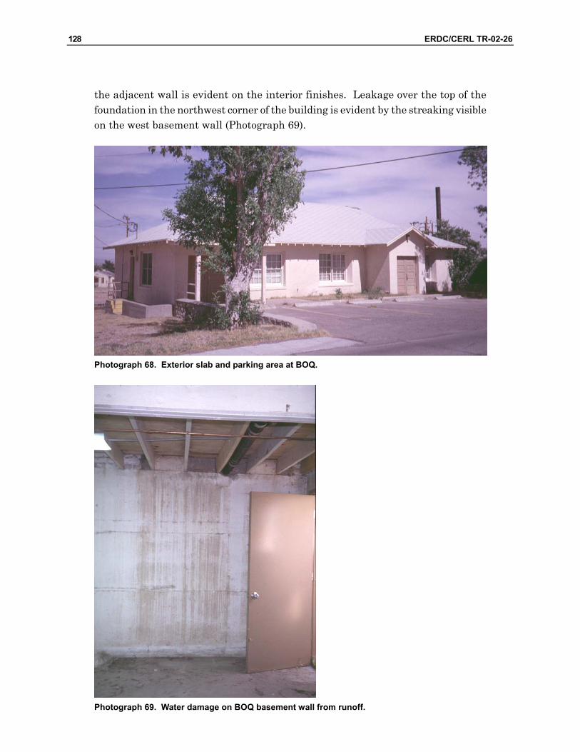
128 ERDC/CERL TR-02-26
the adjacent wall is evident on the interior finishes. Leakage over the top of the foundation in the northwest corner of the building is evident by the streaking visible on the west basement wall (Photograph 69).
Photograph 68. Exterior slab and parking area at BOQ.
Photograph 69. Water damage on BOQ basement wall from runoff.
p p*^rj
ipi
m -'^
- —
1 j
1
1. A
1 1
■ ■■ 1 4 t 11 1
^

ERDC/CERL TR-02-26 129
The south portion of the basement should be accessible through a basement level door at the south side of the building (Drawing 8,L; Photograph 69). However, this entry was blocked by sedimentation, apparently deposited by runoff collecting against the south side of the foundation.
The site should be regraded to provide positive drainage away from the building. Drainage structures may be required at the west side of the site. As the site slopes dramatically to the east, runoff can be directed toward the south and east of the building and into the arroyo.
7.7 Recommendations
The BOQ building is fundamentally sound. The structural systems appear to be performing as intended. The exterior closure systems are generally intact. Also, the original interior construction is reasonably sound, with the exception of the wa-ter intrusion at the west wall. This building has recently been renovated so with modest repair and refinishing, it should remain completely serviceable.
The following tasks will be appropriate for upgrading this facility. The tasks are common and straightforward, and should be completed without great difficulty.
• Redevelop the site’s drainage at the west and south sides of the building to ensure positive drainage away from the building.
• Repair missing shingles. Consider increasing the slope of the porch at the north door on the west wall and installing metal roofing more consistent with the porch roofing depicted on original designs of surrounding buildings.
• Replace the south basement door with a historically appropriate style. • Examine the evaporative cooler for leakage; repair as appropriate. • Perform exterior repairs and repaint walls and trim. • Examine the floor framing adjacent to the main (west) entry. Repair the sub-
floor and/or underlayment as required. • Thoroughly clean the carpet, or replace if necessary. • Perform routine interior repairs and repaint walls and ceilings.
130 ERDC/CERL TR-02-26
8 Building 7167: Conference Center
8.1 Description
The conference center was originally built as a mess hall and has recently been con-verted to a conference center. It is assumed that the building will serve a similar function in the future and its configuration will not change dramatically. It is a one-story rectangular building, 35 ft wide by 144 ft long, or 2118 sq ft in plan area.
The main entry to the former mess hall is through a porch on the west side of the building. The south half of the building was originally the dining area, and is now an open conference space. The north half of the building was the food preparation area, and is now partitioned into office space.
A small attendant’s apartment was located at the north end of the building, with its own entry at the north wall. An open archway through the building (laterally) de-fined the kitchen area from the attendant’s area. It has since been closed and all spaces are now offices. This archway is a significant element in the building’s origi-nal design.
The foundation is reinforced concrete, with one row of interior piers running longitudinally down the centerline of the building. Wood floor joists frame the floor in two spans. The exterior walls are terra cotta tile masonry with a stucco exterior finish. The roof structure consists of wood trusses, purlins, and rafters spanning the width of the building.
The interior of the building is finished in painted plaster or gypsum wallboard. The floors are either carpeted or vinyl composition tile. Roll vinyl flooring was installed in the washrooms and utility room. The ceiling in the conference room is composed of painted gypsum board, while a suspended acoustical ceiling has been installed throughout the remainder of the building.
A new wall has been constructed at the interior of the south end of the building, which reportedly protects a significant mural painted on the interior surface of the south wall.

ERDC/CERL TR-02-26 131
An exterior photograph of Building 7167 is shown in Photograph 70.
Photograph 70. Exterior photograph of Building 7167 (conference center).
88..22 Condition Assessment
88..22..11 Substructure
8.2.1.1 Foundation Construction
Foundation walls were observed around the building’s perimeter from the exterior. Any occurrence of cracking, deformation, deflection in either horizontal or vertical plane, differential settlement, heaving, lateral displacement, leakage, concrete dete-rioration, exposed reinforcing, or other signs of distress were noted.
The foundation is visible around the building’s perimeter, with the exception of the north side, where it is concealed by a porch. The top of the foundation wall is level, and there is generally no evidence of differential settlement or displacement.
Parging is peeling off of the concrete at the south wall (Drawing 9, A). There are several minor cracks in the foundation. For example, there are some minor cracks that occur at the crawl space vents on the east and south walls (Drawing 9, B). One noticeable crack occurs at the southwest corner of the building (Drawing 9, C; Photograph 71). This crack has been patched in the past, but has since broken
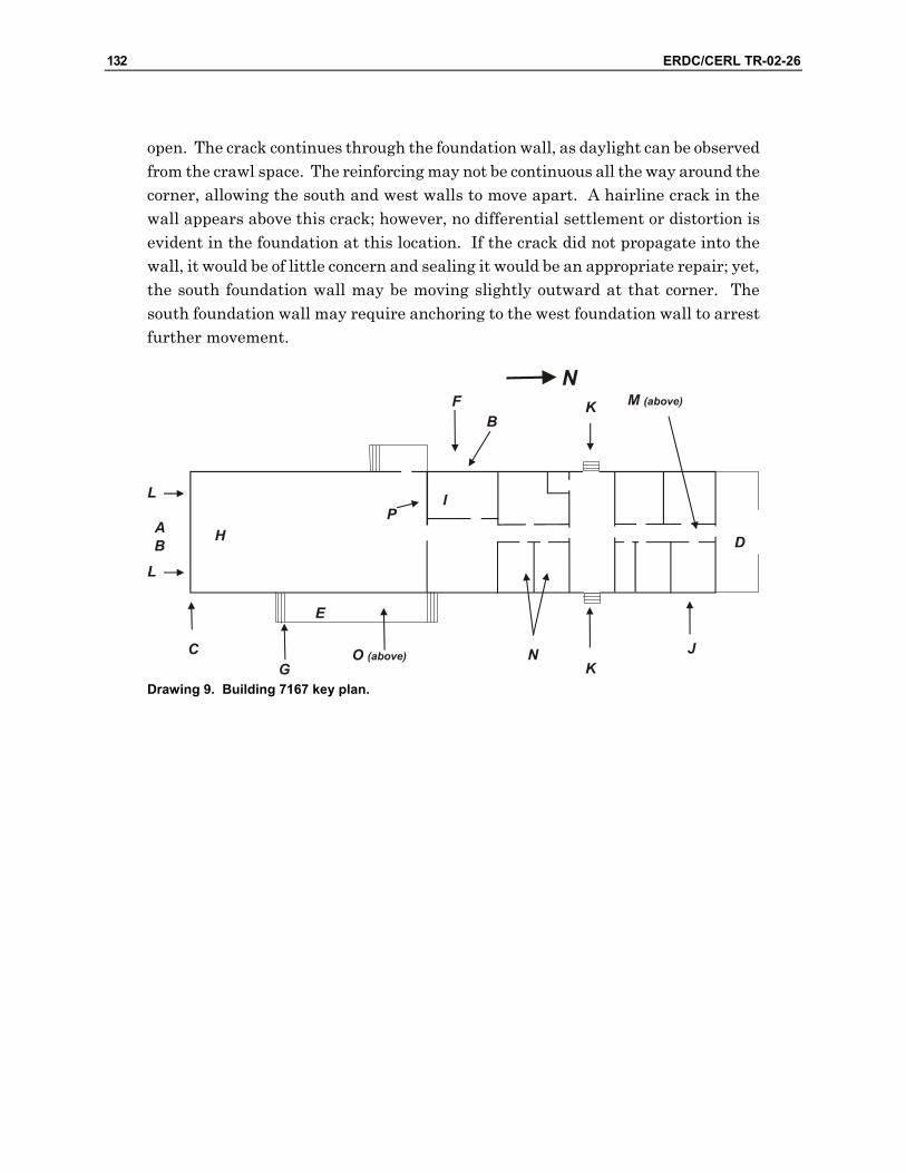
132 ERDC/CERL TR-02-26
open. The crack continues through the foundation wall, as daylight can be observed from the crawl space. The reinforcing may not be continuous all the way around the corner, allowing the south and west walls to move apart. A hairline crack in the wall appears above this crack; however, no differential settlement or distortion is evident in the foundation at this location. If the crack did not propagate into the wall, it would be of little concern and sealing it would be an appropriate repair; yet, the south foundation wall may be moving slightly outward at that corner. The south foundation wall may require anchoring to the west foundation wall to arrest further movement.
Drawing 9. Building 7167 key plan.

ERDC/CERL TR-02-26 133
Photograph 71. Conference center foundation crack.
The interior of the foundation wall and interior piers were accessible from the crawl space. No deflection or differential settlement in the foundation wall was observed from the interior. The piers were generally plumb and aligned. No settlement, overturning, misalignment, or other signs of distress were evident.
The access door to the crawl space is secured only with a bent nail. This access should be secured when rehabilitating the building’s exterior.
8.2.1.2 Slabs on Grade
The porch slab on the north side of the building is cracked in a north-south direction (Drawing 9, D; Photograph 72). The slab on the west porch is also cracked (Drawing 9, E; Photograph 73). The wheelchair access ramp on the east side of the building is also cracked and is falling away from the building (Drawing 9, F).
V V,,^v.>SvS^*'
■v>-..

134 ERDC/CERL TR-02-26
Photograph 72. Crack in north porch slab of Conference Center.

ERDC/CERL TR-02-26 135
Photograph 73. Crack in west porch of Conference Center.
The stairs at the west porch are badly cracked, especially the south stairs (Drawing 9, G; Photograph 74). The exterior retaining wall appears to be falling away from the building, and opening a crack between the wall and the stairs.

136 ERDC/CERL TR-02-26
Photograph 74. Badly cracked Conference Center stairs.
These cracks appear to be caused by uneven settlement of the slabs, possibly be-cause of insufficient compaction in the fill below them. While it may be possible to repair these concrete structures, it may be more practical to rebuild them.
8.2.2 Superstructure
Structural components were examined in all locations of the building. Where fram-ing or load-bearing members were concealed, floor or wall assemblies were exam-ined for signs of distress. Any occurrence of cracking, deformation, deflection in ei-ther horizontal or vertical plane, differential settlement, lateral displacement, and other signs of distress in any load-bearing components were noted.
8.2.2.1 Floor Construction
The floor did not exhibit any signs of extraordinary bounce or deflection when walk-ing, bouncing, or jumping at any location. It was also reasonably level and did not exhibit any significant sagging or settlement.

ERDC/CERL TR-02-26 137
Floor framing was exposed to the basement below. Joists and beams overall ap-peared to be level, true, and free from any significant splitting, cracking, overstress-ing, warping, or deterioration.
Hot water piping installed under the floor has been cut into the bottom edges (the tension side) of the floor beam at the south end of the crawlspace side (Drawing 9, H; Photograph 75). However, no deflection is evident in the floor at this location. This piping should be re-routed and the cut beams repaired.
Photograph 75. Notched floor beam in Conference Center crawl space.
The floor was spongy only at one area in the utility room on the building’s east side (Drawing 9, I; Photograph 76). A utility sink is present at the south wall of this room. An electrical panel box is also mounted adjacent to the sink. The flooring and underlayment have been damaged by water overflow or leakage. Furthermore, joists immediately below this area had been cut to allow conduit servicing the panel box from below (Photograph 77). The conduit should be rerouted and the cut joists repaired in an adaptive use project. Separating the sink from the panel box would also be advisable.

138 ERDC/CERL TR-02-26
Photograph 76. Spongy floor area on Conference Center utility room.
Photograph 77. Cut flooring joists under the spongy floor area.

ERDC/CERL TR-02-26 139
8.2.2.2 Roof Construction
The roof’s structural components were concealed with the exception of the rafter ends at the open eaves.
When viewed from the ground, the side of each gable and the north and south hip ends appear to be quite flat and straight. The ridge also appears to be straight. No sagging was evident in any part of the roof. The rafter ends were aligned at the eaves with no sign of sagging or deflection. When viewed from the interior, no cracking, sagging, or deformation in the ceiling is apparent.
Evaporative coolers or air conditioning units have been installed within the attic space. No deflection is evident at these locations.
The porches’ columns are boxed in with wood trim, and cannot be observed. This trim work is deteriorated at several columns and splitting and deterioration is evi-dent (Photograph 78). Stucco “bases” had been added around the bottoms of col-umns. This detail was not flashed or sealed, and water penetration and damage is evident. While the load-bearing members of the column assembly could not be ob-served, similar deterioration may have occurred. The structures supporting the porch’s roof must be thoroughly evaluated as part of an adaptive use program.
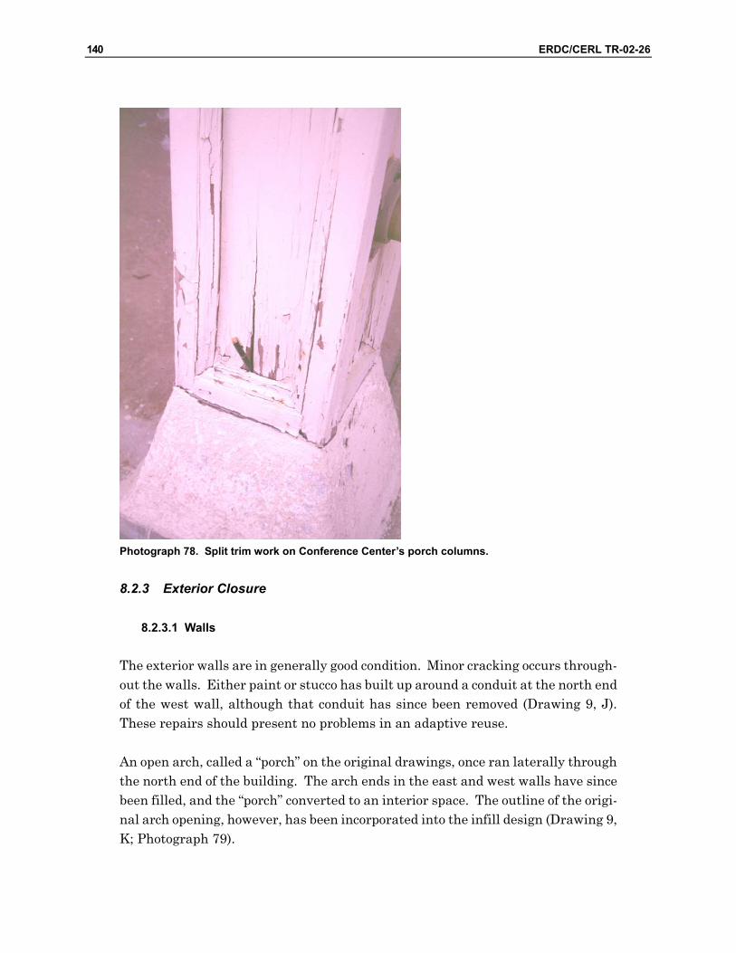
140 ERDC/CERL TR-02-26
Photograph 78. Split trim work on Conference Center’s porch columns.
8.2.3 Exterior Closure
8.2.3.1 Walls
The exterior walls are in generally good condition. Minor cracking occurs through-out the walls. Either paint or stucco has built up around a conduit at the north end of the west wall, although that conduit has since been removed (Drawing 9, J). These repairs should present no problems in an adaptive reuse.
An open arch, called a “porch” on the original drawings, once ran laterally through the north end of the building. The arch ends in the east and west walls have since been filled, and the “porch” converted to an interior space. The outline of the origi-nal arch opening, however, has been incorporated into the infill design (Drawing 9, K; Photograph 79).
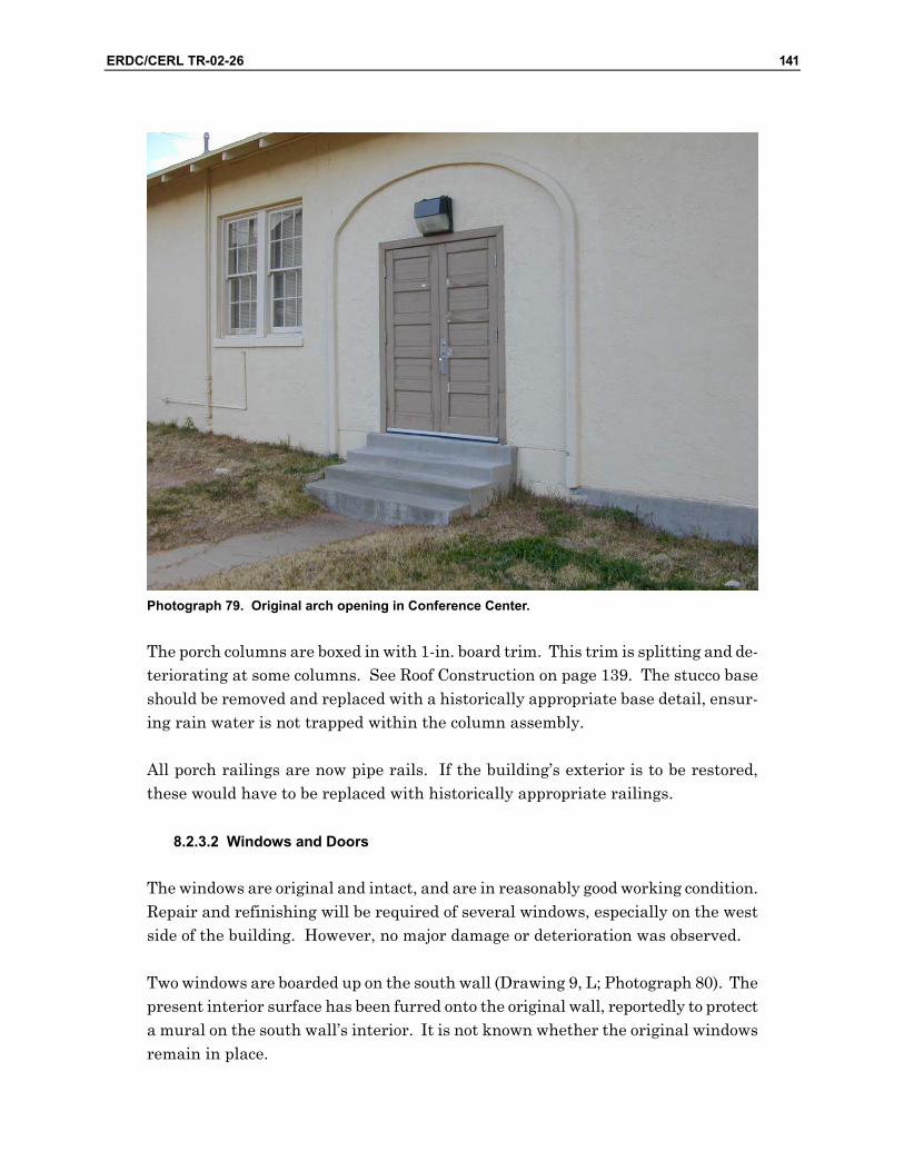
ERDC/CERL TR-02-26 141
Photograph 79. Original arch opening in Conference Center.
The porch columns are boxed in with 1-in. board trim. This trim is splitting and de-teriorating at some columns. See Roof Construction on page 139. The stucco base should be removed and replaced with a historically appropriate base detail, ensur-ing rain water is not trapped within the column assembly.
All porch railings are now pipe rails. If the building’s exterior is to be restored, these would have to be replaced with historically appropriate railings.
8.2.3.2 Windows and Doors
The windows are original and intact, and are in reasonably good working condition. Repair and refinishing will be required of several windows, especially on the west side of the building. However, no major damage or deterioration was observed.
Two windows are boarded up on the south wall (Drawing 9, L; Photograph 80). The present interior surface has been furred onto the original wall, reportedly to protect a mural on the south wall’s interior. It is not known whether the original windows remain in place.
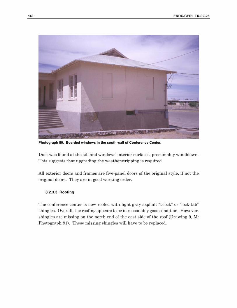
142 ERDC/CERL TR-02-26
Photograph 80. Boarded windows in the south wall of Conference Center.
Dust was found at the sill and windows’ interior surfaces, presumably windblown. This suggests that upgrading the weatherstripping is required.
All exterior doors and frames are five-panel doors of the original style, if not the original doors. They are in good working order.
8.2.3.3 Roofing
The conference center is now roofed with light gray asphalt “t-lock” or “lock-tab” shingles. Overall, the roofing appears to be in reasonably good condition. However, shingles are missing on the north end of the east side of the roof (Drawing 9, M: Photograph 81). These missing shingles will have to be replaced.

ERDC/CERL TR-02-26 143
Photograph 81. Missing shingles on Conference Center.
Water stains occur in both the men’s and women’s washrooms on the west side of the building (Drawing 9, N). For instance, staining appears on each ceiling, and the partition between the two rooms. A drain-waste-vent stack is enclosed in this parti-tion and penetrates the roofing at this location. The original plaster ceiling pre-vents examination of the underside of the roof sheathing. However, leakage at the vent stack is suspected. The vent stack should be reflashed as part of an adaptive use project.
No other water leakage was evident when viewed from the building’s interior.
Re-roofing is common in an adaptive use project. The historic appropriateness of the existing style of shingle will have to be determined.
The roofing on the west porch is the same style of asphalt shingle (Drawing 9, O). However, the slope of the porch roof is only approximately 1:12 or 2:12, as opposed to approximately 4:12 for the main roofs. Shingle roofing is inappropriate for a roof of such low slope. An alternative type of roofing should be considered for an adap-tive reuse design.

144 ERDC/CERL TR-02-26
Some minor paint deterioration is evident in the exposed eaves. However, scraping, filling, priming, and painting should be sufficient for an adaptive use project.
The paint has deteriorated on the gable vents at the north and south ends of the roof. Scraping, priming, and painting should be a sufficient repair.
8.2.4 Interior Construction
It is assumed that the current interior configuration will remain essentially as it is. Therefore, no extended discussion will be made about apparent modifications to the building’s plan or description of existing features.
All partition construction appears to be sound. Flush wood doors and contemporary trim are used throughout the interior. Trim is in reasonably good condition, al-though miscellaneous minor repairs will be necessary.
All finishes are in reasonably good condition. However, wind blown dust has infil-trated the building. A thorough cleaning will be required. Interior painting will also be advisable.
The finished floor and underlayment in the utility room should be replaced. See Floor Construction on page 136.
All painted plaster or gypsum wallboard wall finishes are sound. The ceiling fin-ishes are clean with the exception of the aforementioned leaks in the washrooms. Once the leaks are stopped, patching and repainting the wall and replacing the ceil-ing tiles should remain effective repairs.
8.2.5 Services
Plumbing, HVAC, and electrical services were reported to be serviceable and gener-ally perform as intended. All plumbing fixtures were found to be operable. The ca-pacity and performance of the evaporative coolers or air conditioning could not be verified, although they were reported to be performing as intended. Nonetheless, each unit could be turned on at the circuit breaker box in the utility room.
All lights were operable. Some sconce lights that were adjacent to the doors on the north side of the conference room, were damaged by these doors (Drawing 9, P). Damage to these lights can be prevented by installing door stops to limit the doors’ swing. An appropriate lighting design will have to be developed according to the future occupant and function.
ERDC/CERL TR-02-26 145
The illumination in the office areas seemed to be excessive for the purposes. Multi-ple 4-tube fluorescent fixtures in each office may not represent the optimum lighting design. The region’s potential for daylight, combined with task lighting at desks or workstations, should certainly provide better life-cycle lighting economy as well as improved lighting performance.
A sampling of receptacles indicated electrical power was also active.
8.3 Recommendations
It is assumed the conference center will remain in its current occupancy and con-figuration. This building should remain completely serviceable in its present condi-tion. However, the following tasks would be appropriate for upgrading the building so that it would be consistent with those of the adjacent buildings. These tasks are common and straightforward, and should be completed without great difficulty.
• It may be possible to repair the concrete slabs and stairs at the west and north porches and the wheelchair ramp on the east side of the building. However, it may be more practical to rebuild these items. If they are rebuilt, ensure the fill below the slabs and ramp is sufficiently compacted, that the slabs and ramp themselves are sufficiently reinforced, and that bearing is uniform throughout their areas to prevent local overstressing and cracking.
• Repair the cut floor joists, subfloor, and underlayment under the utility room. • Re-flash the soil vent at the washrooms on the west side of the building
where it penetrates the roof. • Alternatively, replace the roofing with a historically appropriate style of
shingle. Replace the porch’s roofing with metal roofing to be consistent with the original design.
• Repair the porch columns’ enclosures and restore the original base detail. Replace pipe railings with historically appropriate balusters.
• Perform the necessary minor repairs to the buildings’ exterior (stucco sur-faces, windows, and trim), and refinish.
• Perform routine interior repairs and repaint walls and ceilings.
146 ERDC/CERL TR-02-26
Appendix A: Building Condition Matrix This appendix (published under a separate cover) provides an “at-a-glance” display of the each building’s condition, described by major systems and components. Two perspectives are provided. The “Serviceability” perspective represents the system’s or component’s condition in their current state. The “Rehabilitation” perspective considers the appropriateness of the existing system or component within a reha-bilitation context, as well as its current serviceability or performance.

ERDC/CERL TR-02-26 147
Appendix B: Rehabilitation Schematic Designs
B.1 General
Schematic-level designs were developed for the rehabilitation of Buildings 7151, chapel; 7155, gymnasium; and 7157 – 7159, barracks. The purpose of this design work was to present concepts for these buildings’ continued use and service to Fort Bliss’ requirements.
At this time, no specific tenants have been identified for the buildings. Therefore, there is currently no identified occupant and no specific programmatic require-ments. Fort Bliss is attempting to attract tenants, and exhibit the buildings’ poten-tial. Buildings 7151 and 7155 are to be considered as simply “buildings,” no longer limited to their most recent functions. Therefore, designations as “chapel” and “gymnasium” are discontinued. Buildings 7157 – 7159 are candidates for office-type occupancies, or a variety of housing-type occupancies.
Designs portray rehabilitation of the buildings’ exteriors in a historically appropri-ate fashion. Minimal interior reconfiguration is proposed for Buildings 7151 and 7155. Buildings 7157-1759 are reconfigured to represent potentially feasible occu-pancies.
As these designs are developed only to the schematic level of detail, they portray the fundamental composition and architectural character of the buildings. It must be recognized that further development will be required to enable construction of these designs. This will include completion of Design Development and Construction Documentation services, and incorporating the final engineering of the structural and mechanical systems. However, it is felt that the schematic designs have been developed in a thorough enough manner to enable their completion without signifi-cant revisions to the overall layout.

148 ERDC/CERL TR-02-26
B.2 Design Concept Summaries
B.2.1 Building 7151
This building is a one-story rectangular building, 37 ft wide by 96.5 ft long, or 3570 sq ft in plan area.
The interior consists primarily of a large, clear span central space, of approximately 1880 square ft. A gabled ceiling follows the contour of the roof.
A mezzanine is located at the south end of the building, overlooking the interior space. Adjacent to the main entry, under the mezzanine, is a room of approximately 140 sq ft. This space may be used as an enclosed office, or for reception, access con-trol, storage, or a similar function. The schematic design retains the open mezza-nine. However, the mezzanine could be enclosed if further enclosed space is re-quired.
At the north end of the building there are two restrooms and a small closet or stor-age space.
No partitioning is shown in the main space. The elegance of the roof structure (i.e., the composite wood trusses) suggests that it should remain visible throughout the space. Any subdivision of this space could be accomplished by using furniture or equipment groupings, office landscape systems, or other less intrusive methods of space division. The two smaller spaces at the north and south ends of the building would be available for office space, enclosed storage, or similar uses.
As the building is one story, accessibility features include only a ramp to the north-west exterior door, and an elevator to the mezzanine adjacent to the main entry.
The exterior includes no major modifications from the building’s current configura-tion.
The original nave windows will be reinstalled.
The entry at the northwest corner of the building is made accessible. This is the closest entry to parking, and grade is at the highest elevation relative to the finish floor level.
A historically appropriate door is shown at the south entry. It is assumed that the wood walkway spanning the swale at the main entry will remain.

ERDC/CERL TR-02-26 149
The steeple remains intact, as it is a significant feature of this building.
The schematic design portrays upgraded washroom facilities. Since no further me-chanical or electrical features are portrayed, additional mechanical and electrical upgrades will be necessary for a rehabilitation design, and will have to be included with Design Development tasks. Replacing the fan coil heaters that are suspended from the roof trusses with baseboard or radiant panels around the building’s pe-rimeter, would be a less obtrusive solution to heating and cooling.
CLOSET
OPEN AREA
OFFICE/CONTROL
FOYERMEZZANINE ABOVE
RAMP
LIFT
MECH ROOM
Building 7151 Floor Plan
Building 7151 South Elevation Building 7151 North Elevation
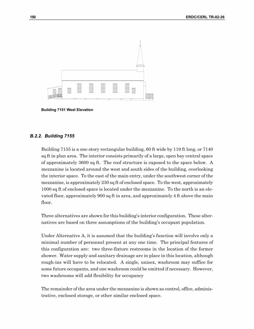
150 ERDC/CERL TR-02-26
Building 7151 West Elevation
B.2.2. Building 7155
Building 7155 is a one-story rectangular building, 60 ft wide by 119 ft long, or 7140 sq ft in plan area. The interior consists primarily of a large, open bay central space of approximately 3600 sq ft. The roof structure is exposed to the space below. A mezzanine is located around the west and south sides of the building, overlooking the interior space. To the east of the main entry, under the southwest corner of the mezzanine, is approximately 230 sq ft of enclosed space. To the west, approximately 1000 sq ft of enclosed space is located under the mezzanine. To the north is an ele-vated floor, approximately 900 sq ft in area, and approximately 4 ft above the main floor.
Three alternatives are shown for this building’s interior configuration. These alter-natives are based on three assumptions of the building’s occupant population.
Under Alternative A, it is assumed that the building’s function will involve only a minimal number of personnel present at any one time. The principal features of this configuration are: two three-fixture restrooms in the location of the former shower. Water supply and sanitary drainage are in place in this location, although rough-ins will have to be relocated. A single, unisex, washroom may suffice for some future occupants, and one washroom could be omitted if necessary. However, two washrooms will add flexibility for occupancy
The remainder of the area under the mezzanine is shown as control, office, adminis-trative, enclosed storage, or other similar enclosed space.
ERDC/CERL TR-02-26 151
Under Alternative B, it assumed that a significant number of personnel will occupy the building (perhaps 100 or more), and will require shower facilities in addition to basic washroom accommodations. This alternative maximizes the existing space on the west side of the building as restroom / locker / shower facilities.
Male and female facilities are provided. While a male/female occupancy ratio is un-known, it is assumed a larger male population will be present. Twelve sanitary fix-tures are shown in the Men’s washroom, and five are shown for the Women’s wash-room. Each shower accommodates six. Water supply and sanitary drainage are in place at this location, although lines will have to be extended to the south end of this space, and rough-ins will have to be relocated.
Plumbing fixtures and partitions can be installed below the elevated windowsills on the west side of the building. The two windows at the southwest corner, however, will have to be glazed with translucent or textured glass, as sanitary fixtures are located there.
Column showers, multi-station lavatory fixtures, and (in the Men’s washroom) trough urinals are shown. All of these items are currently available from a number of manufacturers. The purpose of using these group-type fixtures is to minimize the amount of new supply and sanitary piping required, as well as to maximize utility of the existing space. However, conventional independent fixtures can also be used within the same spaces, if they are more appropriate for a future occupant.
Alternative C portrays a simple building addition, if expansion becomes necessary to accommodate a future tenant. No interior configuration is shown in the addition.
Two washroom facilities are shown. The addition is set apart from the original building. Exterior materials would be similar to the existing building. The same shingles can be used. The wall finish could be either stucco or exterior insulation and finish system (EIFS). A stucco surface will certainly be more consistent with the architectural context. However, EIFS will provide a more economical solution, and may be an aesthetically acceptable alternative.
The proportions of the addition are similar to the existing building. Detailing is in-tended to be consistent with the existing building, but to not compete with it. Therefore, exterior features are greatly simplified. Window openings are propor-tional to the existing building, although the expressed sills and lintels have been omitted. Surface features would be scored into the exterior surface, as opposed to being rendered in full relief. Doing so would provide visual relief of unbroken sur-faces, as well as provide control joints for the wall construction.

152 ERDC/CERL TR-02-26
Storm water management becomes an issue at the west side of the existing build-ing. While the schematic nature of this design does not portray details, it is antici-pated gutters will be necessary to carry rainfall off the west side of the existing building, the east side of the addition, and the connecting structure. Gutters would be integrated into the fascia of the connecting structure, which would be recessed from the north and south elevations of the addition. Gutters would be added to the west eave of the existing building, but can be screened by extending the rafters to carry the gutter and a fascia outboard of the existing wall line. A similar detail would be followed at the east eave of the addition. Gutters themselves would be half-round and downspouts would be straight rectangular in profile to be more con-sistent with the style of the period.
No significant reconfiguration is shown within the main interior spaces in any of the three options. As the mezzanine was originally constructed as a gallery, the floor consists of a series of risers, as opposed to a single level floor surface. This configu-ration remains in Alternatives A and B.
Alternative C, however, shows a level floor for the mezzanine, which by necessity would be at the top riser level of the existing gallery. If future occupancy requires a level floor, it can be constructed at the mezzanine for any of the alternative designs.
The schematic designs show the building’s exterior in essentially its original con-figuration. Historically appropriate doors are shown to replace the flush doors cur-rently in place. Fenestration remains unchanged, with the exception of privacy glazing installed in two the southwest windows for Alternative B.
Accessibility features include the following. Only the existing ramp on the east side of the building is shown on Alternatives A and B. A ramp to the northwest exterior door is shown on Alternative C. This is the closest entry to parking, and is at a higher elevation than most of the building’s perimeter. A lift to the elevated floor level, and a lift to the mezzanine are shown with Alternative C. A wheelchair lift is shown for access to the elevated floor in all alternatives. An elevator is shown for access to the mezzanine for Alternative C. Any of these accessibility features, how-ever, can be incorporated into any of the alternatives.
Fire exits from the mezzanine, which have previously been removed, are added at the west and east sides of the existing building. If, however, future occupancy will not require occupancy and egress from the mezzanine, these fire stairs can be omit-ted and the existing door openings can be returned to the window openings por-trayed in the original design.
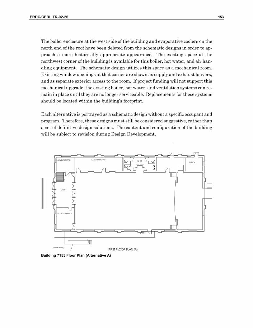
ERDC/CERL TR-02-26 153
The boiler enclosure at the west side of the building and evaporative coolers on the north end of the roof have been deleted from the schematic designs in order to ap-proach a more historically appropriate appearance. The existing space at the northwest corner of the building is available for this boiler, hot water, and air han-dling equipment. The schematic design utilizes this space as a mechanical room. Existing window openings at that corner are shown as supply and exhaust louvers, and as separate exterior access to the room. If project funding will not support this mechanical upgrade, the existing boiler, hot water, and ventilation systems can re-main in place until they are no longer serviceable. Replacements for these systems should be located within the building’s footprint.
Each alternative is portrayed as a schematic design without a specific occupant and program. Therefore, these designs must still be considered suggestive, rather than a set of definitive design solutions. The content and configuration of the building will be subject to revision during Design Development.
Building 7155 Floor Plan (Alternative A)

154 ERDC/CERL TR-02-26
Building 7155 Floor Plan (Alternative B)
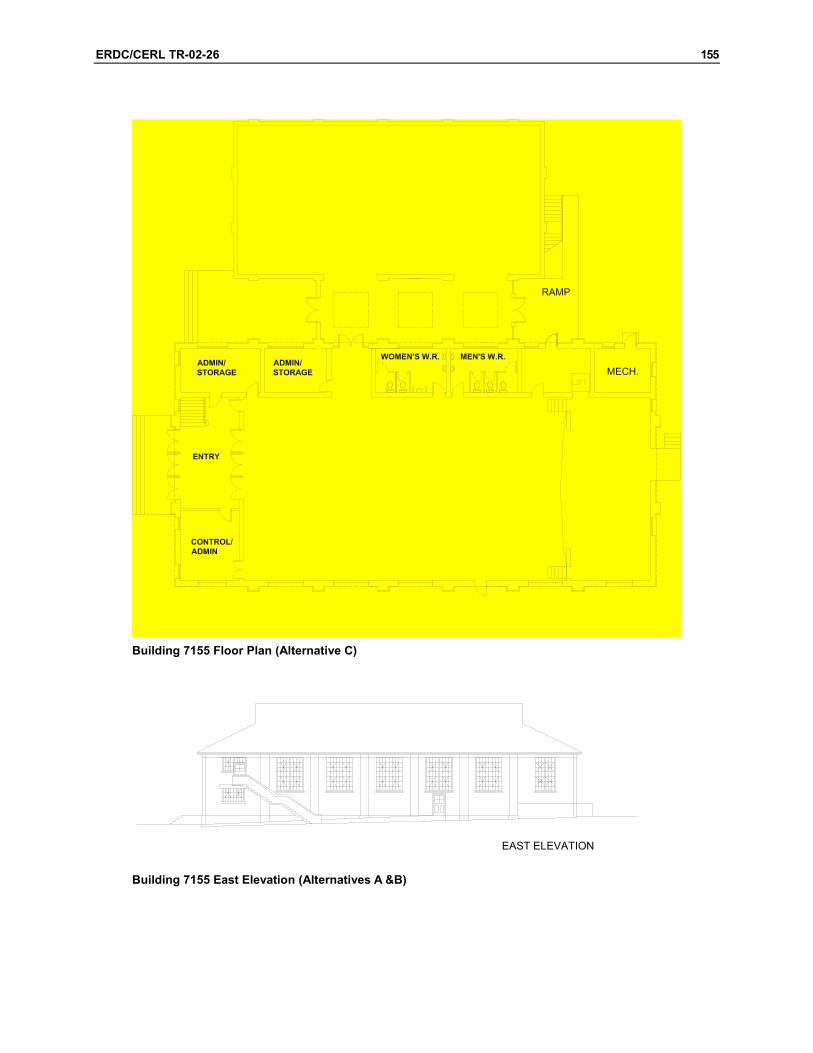
ERDC/CERL TR-02-26 155
Building 7155 Floor Plan (Alternative C)
EAST ELEVATION
Building 7155 East Elevation (Alternatives A &B)

156 ERDC/CERL TR-02-26
SOUTH ELEVATION
Building 7155 South Elevation (Alternatives A & B)
Building 7155 North Elevation (Alternatives A & B)
WEST ELEVATION
Building 7155 West Elevation (Alternatives A & B)

ERDC/CERL TR-02-26 157
SOUTH ELEVATION
Building 7155 South Elevation (Alternative C)
NORTH ELEVATION
Building 7155 North Elevation (Alternative C)
WEST ELEVATION Building 7155 West Elevation (Alternative C)
B.2.3. Buildings 7157, 7158, and 7159
Buildings 7157, 7158, and 7159 are two-story rectangular buildings, 35 ft wide by 110 ft long, or 3,850 sq ft in enclosed plan area. Each floor was identical in plan, although each building has been partitioned in different configurations over the years. There is an 11 ft wide open porch on the east side of each building, running its full length.
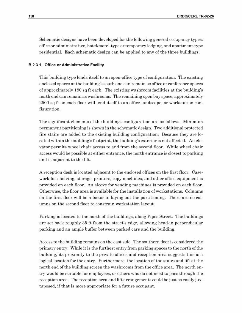
158 ERDC/CERL TR-02-26
Schematic designs have been developed for the following general occupancy types: office or administrative, hotel/motel-type or temporary lodging, and apartment-type residential. Each schematic design can be applied to any of the three buildings.
B.2.3.1. Office or Administrative Facility
This building type lends itself to an open-office type of configuration. The existing enclosed spaces at the building’s south end can remain as office or conference spaces of approximately 180 sq ft each. The existing washroom facilities at the building’s north end can remain as washrooms. The remaining open bay space, approximately 2500 sq ft on each floor will lend itself to an office landscape, or workstation con-figuration.
The significant elements of the building’s configuration are as follows. Minimum permanent partitioning is shown in the schematic design. Two additional protected fire stairs are added to the existing building configuration. Because they are lo-cated within the building’s footprint, the building’s exterior is not affected. An ele-vator permits wheel chair access to and from the second floor. While wheel chair access would be possible at either entrance, the north entrance is closest to parking and is adjacent to the lift.
A reception desk is located adjacent to the enclosed offices on the first floor. Case-work for shelving, storage, printers, copy machines, and other office equipment is provided on each floor. An alcove for vending machines is provided on each floor. Otherwise, the floor area is available for the installation of workstations. Columns on the first floor will be a factor in laying out the partitioning. There are no col-umns on the second floor to constrain workstation layout.
Parking is located to the north of the buildings, along Pipes Street. The buildings are set back roughly 35 ft from the street’s edge, allowing head-in perpendicular parking and an ample buffer between parked cars and the building.
Access to the building remains on the east side. The southern door is considered the primary entry. While it is the furthest entry from parking spaces to the north of the building, its proximity to the private offices and reception area suggests this is a logical location for the entry. Furthermore, the location of the stairs and lift at the north end of the building screen the washrooms from the office area. The north en-try would be suitable for employees, or others who do not need to pass through the reception area. The reception area and lift arrangements could be just as easily jux-taposed, if that is more appropriate for a future occupant.
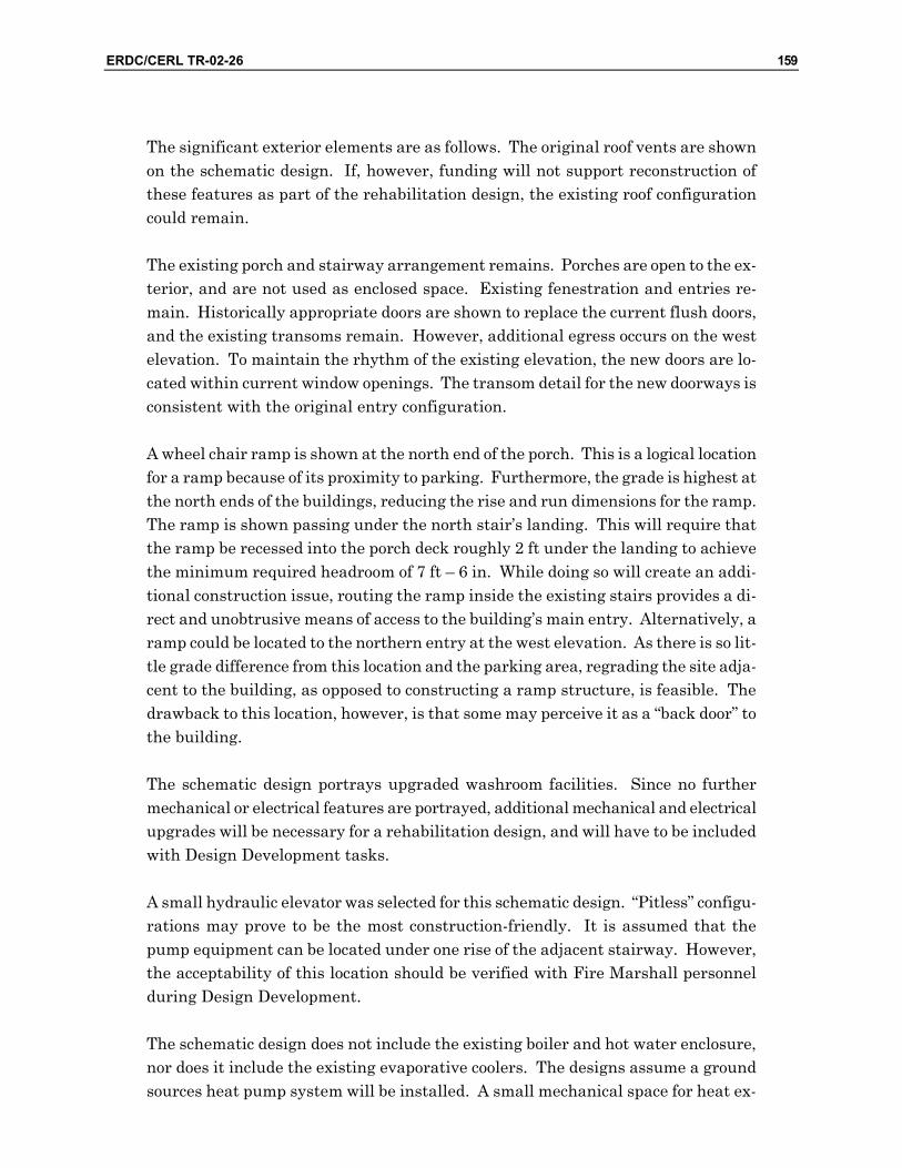
ERDC/CERL TR-02-26 159
The significant exterior elements are as follows. The original roof vents are shown on the schematic design. If, however, funding will not support reconstruction of these features as part of the rehabilitation design, the existing roof configuration could remain.
The existing porch and stairway arrangement remains. Porches are open to the ex-terior, and are not used as enclosed space. Existing fenestration and entries re-main. Historically appropriate doors are shown to replace the current flush doors, and the existing transoms remain. However, additional egress occurs on the west elevation. To maintain the rhythm of the existing elevation, the new doors are lo-cated within current window openings. The transom detail for the new doorways is consistent with the original entry configuration.
A wheel chair ramp is shown at the north end of the porch. This is a logical location for a ramp because of its proximity to parking. Furthermore, the grade is highest at the north ends of the buildings, reducing the rise and run dimensions for the ramp. The ramp is shown passing under the north stair’s landing. This will require that the ramp be recessed into the porch deck roughly 2 ft under the landing to achieve the minimum required headroom of 7 ft – 6 in. While doing so will create an addi-tional construction issue, routing the ramp inside the existing stairs provides a di-rect and unobtrusive means of access to the building’s main entry. Alternatively, a ramp could be located to the northern entry at the west elevation. As there is so lit-tle grade difference from this location and the parking area, regrading the site adja-cent to the building, as opposed to constructing a ramp structure, is feasible. The drawback to this location, however, is that some may perceive it as a “back door” to the building.
The schematic design portrays upgraded washroom facilities. Since no further mechanical or electrical features are portrayed, additional mechanical and electrical upgrades will be necessary for a rehabilitation design, and will have to be included with Design Development tasks.
A small hydraulic elevator was selected for this schematic design. “Pitless” configu-rations may prove to be the most construction-friendly. It is assumed that the pump equipment can be located under one rise of the adjacent stairway. However, the acceptability of this location should be verified with Fire Marshall personnel during Design Development.
The schematic design does not include the existing boiler and hot water enclosure, nor does it include the existing evaporative coolers. The designs assume a ground sources heat pump system will be installed. A small mechanical space for heat ex-

160 ERDC/CERL TR-02-26
change and pump equipment is shown at in the center of the building. As the loca-tion of the coil field is yet unknown, the location of this equipment is subject to revi-sion during Design Development. In any case, exterior air-to-air heat pumps or compressor/condenser units are not required.
The floor-to-ceiling height at the first floor leaves ample space for air distribution. While a suspended ceiling may not be appropriate for the whole building, a discrete enclosure for ductwork would be appropriate. Space is available in the attic for air distribution to the second floor. Alternatively, a discrete enclosure for ductwork can also be constructed. If project funding will not support replacement of the existing heating and evaporative cooling systems, the existing systems can remain in place without compromising the building’s function.
The number and size of windows suggest that natural lighting (i.e., daylighting) may be able to provide at least ambient lighting levels for much of the time the building is occupied. In addition to reducing electrical consumption, reduced light-ing loads also will reduce waste heat and air conditioning load. Natural lighting schemes should be evaluated during Design Development.
LOBBY
ADMIN.
MEN'S
WOMEN'S
OFFICE
CONFERENCEROOM
OPEN OFFICE AREA
0 5'-0" 10'-0" 20'-0" 40'-0"
MECH.
FIRST FLOOR PLAN
STORAGECASEWORK
ELEV.VENDING
N
RAMP
Administrative Facility First Floor Plan

ERDC/CERL TR-02-26 161
OPEN OFFICE AREA
OFFICE
OFFICE
WOMEN'S
SECOND FLOOR PLAN5'-0"0 10'-0" 20'-0" 40'-0"
STORAGECASEWORK
ELEV.CLOSET
N
PRINTERS/COPIERS MEN'S
Administrative Facility Second Floor Plan
EAST ELEVATION
Administrative Facility East Elevation
WEST ELEVATION
Administrative Facility West Elevation

162 ERDC/CERL TR-02-26
B.2.3.2. Hotel / Motel – Type Facility
Six suite-type lodging units are portrayed with this design: three downstairs and three upstairs. As a point of comparison, the proposed design provides accommoda-tions similar to the Army Standard Design for Long Term Visiting Officers Quar-ters, but exceeds the Standard Design in floor area.
Significant features of the building’s configuration are as follows. The existing win-dow location and columns at the first floor essentially dictated placement of parti-tions. Furthermore, the building is not symmetrical about its east/west axis, so con-figurations at the north and south ends are slightly different.
Each suite provides over 800 sq ft of living space. Each suite includes a bedroom, living room, bathroom, and a small kitchen. An alternative configuration is also shown, providing two enclosed rooms for the bedroom and living room. This will lend more flexibility for the building’s occupancy. All first floor bathrooms are ac-cessible.
Building service (i.e., mechanical and custodial spaces) and lounge spaces are pro-vided at the north end of the building. However, other functions can also occupy the lounge space, as appropriate for a future occupant.
Parking is located to the north of the buildings, along Pipes Street. The buildings are set back roughly 35 ft from the street’s edge, allowing head-in perpendicular parking and an ample buffer between parked cars and the building.
Access remains on the building’s east side. The existing porch and stairway ar-rangement remains. Porches are open to the exterior, consistent with the building’s original design.
For each unit to have two means of egress, two additional protected stairwells are provided. Because they are located within the building’s footprint, the building’s exterior is not affected.
Significant exterior elements include the following. The original roof vents are shown on the schematic design. If, however, funding will not support reconstruction of these features as part of the rehabilitation design, the existing roof configuration could remain. The original detailing can be reinstalled the next time the roofing is replaced.

ERDC/CERL TR-02-26 163
The existing porch and stairway arrangement remains. Porches are open to the ex-terior, and are not used as enclosed space.
Existing fenestration and entries remain. Historically appropriate doors are shown to replace the current flush doors. The existing transoms remain. However, the south entry and adjacent window have been juxtaposed to accommodate units’ ac-cess at the south half of the building. To maintain the rhythm of the existing eleva-tion, a door/window combination replaces the current double window.
A wheel chair ramp is shown at the north end of the porch, and is described with the “Office/Administrative” schematic design.
No further mechanical or electrical features are portrayed. However, additional mechanical and electrical upgrades will be necessary for a rehabilitation design, and will have to be included with Design Development tasks.
The schematic design does not include the existing boiler and hot water enclosure, nor does it include the existing evaporative coolers. In the designs, it is assumed that a ground source heat pump system will be installed. Heat exchange and pump equipment is located within the building service space at the south end of the build-ing. A utility closet for air handling and hot water equipment is provided within each unit. Because the location of the coil field is yet unknown, the location of this equipment will be subject to revision during Design Development. In any case, ex-terior air-to-air heat pumps or compressor/condenser units are not required.
The floor-to-ceiling height at the first floor leaves ample space for air distribution within each unit. Distribution to each room from above the entry area is feasible. If project funding will not support replacement of the existing heating system, the ex-isting system can remain in place. Baseboard radiators or radiant panels can be accommodated within the plan, and can be installed where radiators are now lo-cated. However, it would be difficult to retain the existing evaporative cooling dis-tribution within the proposed plan configuration.

164 ERDC/CERL TR-02-26
Hotel / Motel Facility First Floor Plan
Hotel / Motel Facility Second Floor Plan
Hotel / Motel Facility East Elevation
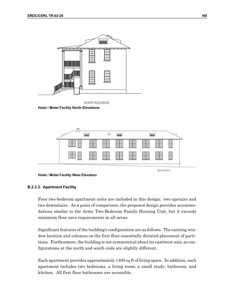
ERDC/CERL TR-02-26 165
Hotel / Motel Facility North Elevations
Hotel / Motel Facility West Elevation
B.2.3.3. Apartment Facility
Four two-bedroom apartment units are included in this design: two upstairs and two downstairs. As a point of comparison, the proposed design provides accommo-dations similar to the Army Two-Bedroom Family Housing Unit, but it exceeds minimum floor area requirements in all areas.
Significant features of the building’s configuration are as follows. The existing win-dow location and columns on the first floor essentially dictated placement of parti-tions. Furthermore, the building is not symmetrical about its east/west axis, so con-figurations at the north and south ends are slightly different.
Each apartment provides approximately 1400 sq ft of living space. In addition, each apartment includes two bedrooms, a living room, a small study, bathroom, and kitchen. All first floor bathrooms are accessible.

166 ERDC/CERL TR-02-26
Access remains on the building’s east side. The existing porch and stairway ar-rangement remains. Porches are open to the exterior, consistent with the building’s original design.
For each unit to have two means of egress, an additional protected stairwell is pro-vided. This will be the primary entry to each apartment. Because it is located within the building’s footprint, the building’s exterior is not affected. The existing entries remain as secondary entries to each apartment.
Significant exterior elements include the following. The original roof vents are shown on the schematic design. If, however, funding will not support reconstruction of these features as part of the rehabilitation design, the existing roof configuration could remain. The original detailing can be reinstalled at a later date.
The existing porch and stairway arrangement remains. Porches are open to the ex-terior, and are not used as enclosed space.
Existing fenestration and entries remain. Historically appropriate doors are shown to replace the current flush doors. The existing transoms remain. A new entry is located at the center of the east elevation on each floor. To maintain the rhythm of the existing elevation, a door/window combination replaces the current double win-dow. The transom detail for the new doorways is consistent with the original entry configuration. An exterior entry is also required in the mechanical space at the west first floor. A door/window combination replaces the current double window in this location as well.
A wheel chair ramp is shown at the north end of the porch, and is described with the “Office/Administrative” schematic design.
No further mechanical or electrical features are portrayed. However, additional mechanical and electrical upgrades will be necessary for a rehabilitation design, and will have to be included with Design Development tasks. The schematic design does not include the existing boiler and hot water enclosure, nor does it include the exist-ing evaporative coolers. In the designs it is assumed a ground source heat pump system will be installed. Heat exchange and pump equipment is located within the mechanical space at the center of the building. A utility closet for air handling and hot water equipment is provided within each unit. Because the location of the coil field is yet unknown, the location of this equipment will be subject to revision dur-ing Design Development. In any case, exterior air-to-air heat pumps or compres-sor/condenser units are not required.

ERDC/CERL TR-02-26 167
The floor-to-ceiling height at the first floor leaves ample space for air distribution within each unit. Distribution to each room from above the central utility core area is feasible.
If project funding will not support replacement of the existing heating system, the existing system can remain in place. Baseboard radiators or radiant panels can be accommodated within the plan, and can be installed where radiators are now lo-cated. However, it would be difficult to retain the existing evaporative cooling dis-tribution within the proposed plan configuration.
Apartment Facility First Floor Plan
Apartment Facility Second Floor Plan

168 ERDC/CERL TR-02-26
Apartment Facility East Elevation
Apartment Facility West Elevation

ERDC/CERL TR-02-26 169
CERL Distribution
Chief of Engineers ATTN: CEHEC-IM-LH (2) Commander USAADACENFB (10) Fort Bliss, TX 79916-6816 Engineer Research and Development Center (Libraries) ATTN: ERDC, Vicksburg, MS ATTN: Cold Regions Research, Hanover, NH ATTN: Topographic Engineering Center, Alexandria, VA Defense Tech Info Center 22304 ATTN: DTIC-O 16 9/02

REPORT DOCUMENTATION PAGE Form Approved
OMB No. 0704-0188 Public reporting burden for this collection of information is estimated to average 1 hour per response, including the time for reviewing instructions, searching existing data sources, gathering and maintaining the data needed, and completing and reviewing this collection of information. Send comments regarding this burden estimate or any other aspect of this collection of information, including suggestions for reducing this burden to Department of Defense, Washington Headquarters Services, Directorate for Information Operations and Reports (0704-0188), 1215 Jefferson Davis Highway, Suite 1204, Arlington, VA 22202-4302. Respondents should be aware that notwithstanding any other provision of law, no person shall be subject to any penalty for failing to comply with a collection of information if it does not display a currently valid OMB control number. PLEASE DO NOT RETURN YOUR FORM TO THE ABOVE ADDRESS. 1. REPORT DATE (DD-MM-YYYY)
09-2002 2. REPORT TYPE
Final 3. DATES COVERED (From - To)
5a. CONTRACT NUMBER 5b. GRANT NUMBER
4. TITLE AND SUBTITLE Condition Assessment of William Beaumont General Hospital Historic Buildings at Fort Bliss, Texas
5c. PROGRAM ELEMENT NUMBER 5d. PROJECT NUMBER MIPR 5e. TASK NUMBER 2042-96
6. AUTHOR(S) Thomas R. Napier and Sheila A. McCarthy
5f. WORK UNIT NUMBER 8. PERFORMING ORGANIZATION REPORT
NUMBER 7. PERFORMING ORGANIZATION NAME(S) AND ADDRESS(ES) U.S. Army Engineer Research and Development Center (ERDC) Construction Engineering Research Laboratory (CERL) PO Box 9005 Champaign, IL 61826-9005
ERDC/CERL TR-02-26
9. SPONSORING / MONITORING AGENCY NAME(S) AND ADDRESS(ES) 10. SPONSOR/MONITOR’S ACRONYM(S) ATZC-DOE-C USAADACENFB
Building 624, Pleasonton Road Fort Bliss, TX 79916-6816
11. SPONSOR/MONITOR’S REPORT NUMBER(S)
12. DISTRIBUTION / AVAILABILITY STATEMENT Approved for public release; distribution is unlimited.
13. SUPPLEMENTARY NOTES Copies are available from the National Technical Information Service, 5285 Port Royal Road, Springfield, VA 22161.
14. ABSTRACT The facilities and landscape features in the William Beaumont General Hospital Historic District at Fort Bliss, Texas are eligible for inclusion in the National Register of Historic Places. Therefore, redevelopment of this area must preserve its character and history. The Fort Bliss Directorate of Environment has developed an Environmental Assessment for the District. A Memorandum of Agree-ment developed between Fort Bliss and the Texas State Historic Preservation Officer includes a requirement to develop a rehabilitation and reuse plan for selected buildings. Among other things, this plan must include a condition assessment and a structure rehabilitation plan. The objective of this project was to assess the present condition of the Bandstand, Chapel, Theater, Gymnasium, three Barracks, a Bachelor Officers Quarters, and a Conference Center in the District. Researchers conducted on-site inspections of all major building elements in all locations within the buildings. Photographs are included to illustrate the condition of selected building elements. Ap-pendix A (published under separate cover) provides an “at-a-glance” display of each building’s condition, described by major systems and components. Appendix B contains schematic-level designs developed for the rehabilitation of the chapel, gymnasium, and the bar-racks.
15. SUBJECT TERMS William Beaumont General Hospital service life historic buildings Fort Bliss, Texas condition assessment Army facilities 16. SECURITY CLASSIFICATION OF: 17. LIMITATION
OF ABSTRACT 18. NUMBER
OF PAGES 19a. NAME OF RESPONSIBLE PERSON
Thomas R. Napier a. REPORT
Unclassified b. ABSTRACT
Unclassified c. THIS PAGE
Unclassified
SAR
170 19b. TELEPHONE NUMBER (in-
clude area code) (217) 352-6511, ext 3497
NSN 7540-01-280-5500 Standard Form 298 (Rev. 8-98) Prescribed by ANSI Std. 239.18
![William Morrison [Berthier, Canada] to W. Beaumont [Saint Louis, … · 2017. 2. 14. · William Morrison [Berthier, Canada] to W. Beaumont [Saint Louis, MO] regarding: attempt to](https://static.fdocuments.in/doc/165x107/61192d10e5869b43ad02ce7e/william-morrison-berthier-canada-to-w-beaumont-saint-louis-2017-2-14.jpg)