Condens 5000 W - bosch-climate.com.au · Condens 5000 W ZSB 30-2 A ... a weather-compensated cont...
44
Operating Instructions Hydronic Gas Condensing Boiler Condens 5000 W 6 720 613 085-00.1O ZSB 30-2 A ...| ZWB 37-2 A ... 6 720 644 144 (2010/09) NZ/AU
Transcript of Condens 5000 W - bosch-climate.com.au · Condens 5000 W ZSB 30-2 A ... a weather-compensated cont...

Operating Instructions
Hydronic Gas Condensing Boiler
Condens 5000 W
6 72
0 61
3 08
5-00
.1O
ZSB 30-2 A ...| ZWB 37-2 A ...
6 72
0 64
4 14
4 (2
010/
09)
NZ/
AU

2
Contents
6 720 644 144 (2010/09)
Contents
1 Key to symbols and safety instructions . . . . . . . . . . . . . . 41.1 Explanation of symbols . . . . . . . . . . . . . . . . . . . . . . . 41.2 Safety instructions . . . . . . . . . . . . . . . . . . . . . . . . . . 6
2 Product details . . . . . . . . . . . . . . . . . . . . . . . . . . . . . . . . . 82.1 Intended use . . . . . . . . . . . . . . . . . . . . . . . . . . . . . . . 82.2 Explanation of model code . . . . . . . . . . . . . . . . . . . . 8
3 Preparing the appliance for use . . . . . . . . . . . . . . . . . . . . 93.1 Turn on the gas service cock . . . . . . . . . . . . . . . . . . 93.2 Turn on the isolators . . . . . . . . . . . . . . . . . . . . . . . . 103.3 Opening the control panel cover . . . . . . . . . . . . . . 113.4 Check the central heating system pressure . . . . . . 123.5 Top up the heating system . . . . . . . . . . . . . . . . . . . 13
4 Operation . . . . . . . . . . . . . . . . . . . . . . . . . . . . . . . . . . . . . 144.1 Overview of controls . . . . . . . . . . . . . . . . . . . . . . . . 164.2 Switching the appliance on/off . . . . . . . . . . . . . . . . 184.3 Starting the central heating . . . . . . . . . . . . . . . . . . 194.4 Setting the heating control unit . . . . . . . . . . . . . . . 214.5 Appliances with hot water cylinder:
setting the hot water temperature . . . . . . . . . . . . . . 224.6 ZWB appliances - setting hot water temperature . . 244.7 Summer mode (central heating off, DHW only) . . . 264.8 Frost protection . . . . . . . . . . . . . . . . . . . . . . . . . . . 274.9 Holiday mode . . . . . . . . . . . . . . . . . . . . . . . . . . . . . 284.10 Further displays . . . . . . . . . . . . . . . . . . . . . . . . . . . 29

3
Contents
6 720 644 144 (2010/09)
5 Carry out thermal disinfection . . . . . . . . . . . . . . . . . . . . . 30
6 Tips on saving energy . . . . . . . . . . . . . . . . . . . . . . . . . . . . 32
7 Troubleshooting . . . . . . . . . . . . . . . . . . . . . . . . . . . . . . . . 34
8 Maintenance . . . . . . . . . . . . . . . . . . . . . . . . . . . . . . . . . . . 36
9 Environment / disposal . . . . . . . . . . . . . . . . . . . . . . . . . . . 37
10 Operating instructions quick reference . . . . . . . . . . . . . . 38
Index . . . . . . . . . . . . . . . . . . . . . . . . . . . . . . . . . . . . . . . . . 39
4 | Key to symbols and safety instructions
6 720 644 144 (2010/09)
1 Key to symbols and safety instructions
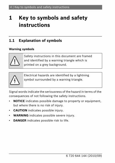
1.1 Explanation of symbols
Warning symbols
Signal words indicate the seriousness of the hazard in terms of the consequences of not following the safety instructions.
• NOTICE indicates possible damage to property or equipment, but where there is no risk of injury.
• CAUTION indicates possible injury.
• WARNING indicates possible severe injury.
• DANGER indicates possible risk to life.
Safety instructions in this document are framed and identified by a warning triangle which is printed on a grey background.
Electrical hazards are identified by a lightning symbol surrounded by a warning triangle.

Key to symbols and safety instructions | 5
6 720 644 144 (2010/09)
Important information
Additional symbols
Notes contain important information in cases where there is no risk of personal injury or material losses and are identified by the symbol shown on the left. They are bordered by horizontal lines above and below the text.
Symbol Meaning
B a step in an action sequence
a reference to a related part in the document or to other related documents
• a list entry
– a list entry (second level)
Table 1

6 | Key to symbols and safety instructions
6 720 644 144 (2010/09)
1.2 Safety instructions
If you smell gas
B Turn off gas tap ( page 16).
B Open windows and doors.
B Do not operate any electrical switches.
B Extinguish any naked flames.
B Leave the building and telephone your gas supply utility and authorised contractor from an outside phone.
If you smell flue gas from the appliance
B Switch off the appliance ( page 16).
B Open windows and doors.
B Inform your heating contractor.
Installation and conversion
B This appliance may only be installed or converted by an approved installer.
B Never modify any parts of the flue system.
B If the appliance has a type B.. flue system: Do not seal off or reduce the size of air vents in doors, windows or walls. If draught-sealed windows are installed, ensure there is an adequate supply of air to the appliance for combustion.
Thermal disinfection
B Risk of scalding!It is imperative to monitor operation at temperatures over 60 °C ( page 30).

Key to symbols and safety instructions | 7
6 720 644 144 (2010/09)
Risk of damage due to operator error
Operator errors can result in injury and damage to property.
B Ensure that children never operate this appliance unsupervised or play with it.
B Ensure that only personnel who can operate this appliance correctly have access to it.
Inspection/Maintenance
B We recommend that you take out a contract to have the system regularly serviced in order to ensure that it functions reliably and safely.
B The user is responsible for the general and environmental safety of the system.
B Only use genuine spare parts!
Combustible materials
B Do not store or use any combustible materials (paper, thinners, paints etc.) in the vicinity of the appliance.
Combustion air/Ambient air
B Keep combustion air/ambient air free of corrosive substances (e.g. halogenated hydrocarbons which contain chlorine or fluorine compounds). In that way corrosion can be prevented.

8 | Product details
6 720 644 144 (2010/09)
2 Product details
2.1 Intended useThe appliance may only be installed in sealed hot-water central heating systems to EN 12828.
Using the appliance for any other purpose will be considered incorrect use. Bosch accepts no liability for any damage resulting from such use.
The commercial and industrial use of appliance to generate process heat is not permitted.
2.2 Explanation of model code
Z Central heating applianceS Cylinder connectionW DHW heatingB Condensing boiler technology30 Output up to 30 kW37 DHW output up to 37 kW-2 VersionA Fan-assisted appliance without draught hood
Condens 5000 W ZSB 30-2 A
ZWB 37-2 A
Table 2

Preparing the appliance for use | 9
6 720 644 144 (2010/09)
3 Preparing the appliance for use
3.1 Turn on the gas service cockB Using a screwdriver, turn the square tap handle so that the slot
is in line with the direction of flow.Slot at right-angles to direction of flow = off.
Fig. 1
6 720 644 144-01 .1O

10 | Preparing the appliance for use
6 720 644 144 (2010/09)
3.2 Turn on the isolatorsB Using a screwdriver, turn the square tap handle so that the slot
is in line with the direction of flow.Slot at right-angles to direction of flow = off.
Fig. 2
6 720 644 143-02.1O
Preparing the appliance for use | 11
6 720 644 144 (2010/09)
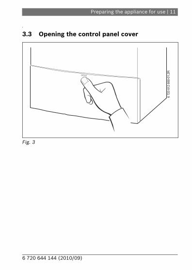
3.3 Opening the control panel cover
Fig. 3
6 72
0 61
2 66
0-01
.2R
12 | Preparing the appliance for use
6 720 644 144 (2010/09)
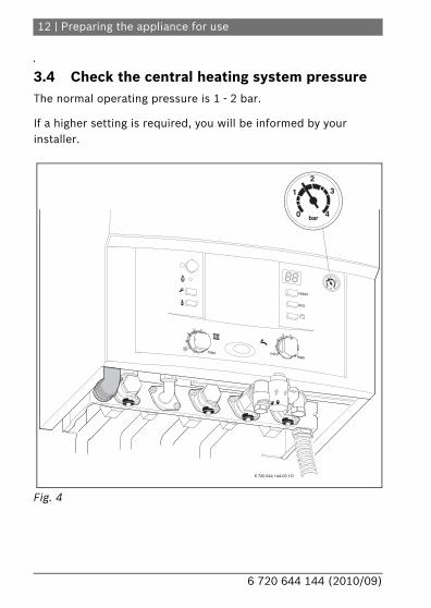
3.4 Check the central heating system pressureThe normal operating pressure is 1 - 2 bar.
If a higher setting is required, you will be informed by your installer.
Fig. 4
6 720 644 144-03.1O
1
0
2
3
4bar

Preparing the appliance for use | 13
6 720 644 144 (2010/09)
3.5 Top up the heating systemThe way in which the heating system is topped up is different on every system. Therefore, you should ask your installer to show you how it is done.
Maximum pressure of 3 bar at maximum heating water temperature must not be exceeded (safety valve will open).
CAUTION: Risk of damaging the appliance.
B Only top up the heating system when the appliance is cold.

14 | Operation
6 720 644 144 (2010/09)
4 OperationThese Operating Instructions apply only to the boiler. Depending on the heating controller used, some functions may be controlled differently.
The following possibilities for controlling the heating system may be employed:
• weather-dependent controller built into the boiler page 16, item 7.
• weather-dependent controller external to the appliance
• room thermostat
Therefore, please read the operating instructions for the heating controller used.
Operation | 15
6 720 644 144 (2010/09)
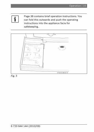
Fig. 5
Page 38 contains brief operation instructions. You can fold this outwards and push the operating instructions into the appliance facia for safekeeping.
max
6 720 613 086-04.1O

16 | Operation
6 720 644 144 (2010/09)
4.1 Overview of controls
Fig. 6
6 720 644 144-04.1O
1819
reset 10
11
12
eco
15161714
4
3
2
5
1
687 9
2013

Operation | 17
6 720 644 144 (2010/09)
1 Flow temperature control2 DHW temperature control3 Chimney sweep button4 Service button5 Burner ON indicator6 Main switch7 Here, a weather-compensated control unit or a time switch
(accessories) can be plugged in8 Display9 Pressure gauge10 reset button11 eco button12 Holiday button13 Drain from pressure relief valve (heating circuit)14 Gas tap15 CH return isolator16 Filling loop (ZWB)17 Cold water tap (ZWB),
cylinder return (ZSB)18 DHW connection (ZWB),
cylinder flow (ZSB)19 CH flow isolator20 Condensate hose
18 | Operation
6 720 644 144 (2010/09)
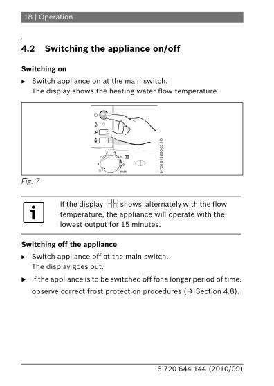
4.2 Switching the appliance on/off
Switching on
B Switch appliance on at the main switch.The display shows the heating water flow temperature.
Fig. 7
Switching off the appliance
B Switch appliance off at the main switch.The display goes out.
B If the appliance is to be switched off for a longer period of time:
observe correct frost protection procedures ( Section 4.8).
If the display shows alternately with the flow temperature, the appliance will operate with the lowest output for 15 minutes.
max
1
2
3 45
6
6 72
0 61
3 89
6-05
.1O

Operation | 19
6 720 644 144 (2010/09)
4.3 Starting the central heatingThe maximum flow temperature can be matched to the heating system by the flow temperature controller. The current flow temperature is shown on the display.
Setting on flow temperature controller
Flow temperature
Sample application
1 Approx. 35 °C
2 Approx. 43 °C
3 Approx. 50 °C Underfloor heating system
4 Approx. 60 °C
5 Approx. 67 °C
6 Approx. 75 °C Radiator heating system
max. Approx. 90 °C Convector heating system
Table 3
With underfloor heating systems, take care to observe the maximum permissible CH flow temperatures.
20 | Operation
6 720 644 144 (2010/09)
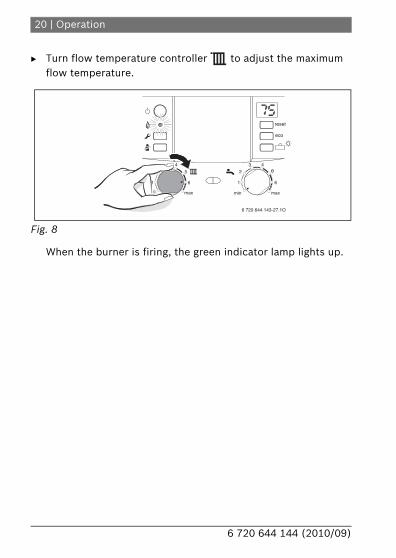
B Turn flow temperature controller to adjust the maximum flow temperature.
Fig. 8
When the burner is firing, the green indicator lamp lights up.
eco
reset
6 720 644 143-27.1O
max
1
23 4
5
6
max
1
2
3 4e
6
min
Operation | 21
6 720 644 144 (2010/09)
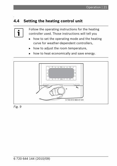
4.4 Setting the heating control unit
Fig. 9
Follow the operating instructions for the heating controller used. Those instructions will tell you
B how to set the operating mode and the heating curve for weather-dependent controllers,
B how to adjust the room temperature,
B how to heat economically and save energy.
9 12 h 15
18
2124 h3
6
6 720 612 660-07.2O

22 | Operation
6 720 644 144 (2010/09)
4.5 Appliances with hot water cylinder: setting the hot water temperature
B Set the DHW temperature on the DHW temperature control .
The set DHW temperature flashes on the display for 30 seconds.
Fig. 10
WARNING: Danger of scalding!
B In normal operation, do not set the temperature higher than 60 °C.
To prevent bacterial contamination such as legionella, we recommend setting the DHW temperature controller to “6” (60 °C).
6 720 644 143-28.1O
max
1
2
3 4
5
6
reset
eco
max
1
23 4
e
6

Operation | 23
6 720 644 144 (2010/09)
eco button
Pressing and holding the eco button until it lights up switches between Comfort mode and Economy mode.
Comfort mode, Eco button is not lit (default setting)
In Comfort mode, the hot water cylinder has priority. The hot water cylinder is heated to the set temperature first. Then the appliance switches to central heating mode.
Economy mode, Eco button lit
In Economy mode, the appliance switches between central heating mode and hot water mode every ten minutes.
DHW thermostat DHW temperature
min Approx. 5 °C (frost protection)
e Approx. 55 °C
6 Approx. 60 °C
max. Approx. 70 °C
Table 4
24 | Operation
6 720 644 144 (2010/09)
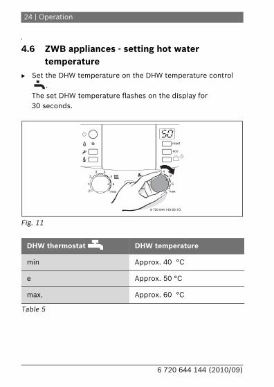
4.6 ZWB appliances - setting hot water temperature
B Set the DHW temperature on the DHW temperature control .
The set DHW temperature flashes on the display for 30 seconds.
Fig. 11
DHW thermostat DHW temperature
min Approx. 40 °C
e Approx. 50 °C
max. Approx. 60 °C
Table 5
eco
reset
max
1
23 4
e
6
6 720 644 143-29.1O
max
1
2
3 4
5
6

Operation | 25
6 720 644 144 (2010/09)
eco button
Pressing and holding the eco button until it lights up switches between Comfort mode and Economy mode.
Comfort mode, (Eco button is not lit - default setting)
The appliance is held constantly at the set temperature. This means that hot water is available almost instantaneously at the tap.Consequently the appliance will switch on at intervals, even if no hot water is being drawn.
Economy mode, Eco button lit
• The water is not heated up until a hot water tap is turned on.
• With a demand signal (only with start delay switched off for the supply of water preheated by solar energy). Briefly turning a hot water tap on and then off signals demand so that the water is then heated up to the set temperature.
If a start delay for the supply of water preheated by solar energy has been set (service function b.F), the appliance does not switch on until the start delay has elapsed.
The demand signal enables gas and water savings.

26 | Operation
6 720 644 144 (2010/09)
4.7 Summer mode (central heating off, DHW only)
B Note position of CH flow temperature control .
B Turn CH flow temperature control anti-clockwise as far as the stop .The heating circuit pump and consequently central heating are switched OFF. However, the DHW supply as well as the power supply to the heating programmer and timer remain 'live'.
Fig. 12
Additional instructions are contained in the operating instructions for the heating programmer.
NOTE: Heating system at risk from frost.
6 720 644 143-30.1O
eco
reset
max
1
2
35
6
max
1
2
3 4e
6
min
Operation | 27
6 720 644 144 (2010/09)
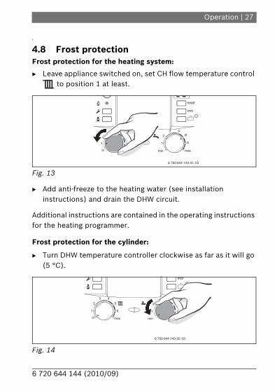
4.8 Frost protectionFrost protection for the heating system:
B Leave appliance switched on, set CH flow temperature control to position 1 at least.
Fig. 13
B Add anti-freeze to the heating water (see installation instructions) and drain the DHW circuit.
Additional instructions are contained in the operating instructions for the heating programmer.
Frost protection for the cylinder:
B Turn DHW temperature controller clockwise as far as it will go (5 °C).
Fig. 14
eco
reset
max
1
2
35
6
max
1
2
3 4e
6
6 720 644 143-31.1O
min
max
1
2
3e
6
max
1
2
3 4
5
6
eco
6 720 644 143-32.1O
min

28 | Operation
6 720 644 144 (2010/09)
4.9 Holiday modeTo switch on holiday mode:
B Press and hold holiday button on the appliance until it lights up, and switch on holiday mode on the heating controller.In holiday mode, heating and DHW heating are switched off; frost protection remains active ( chap. 4.8).
To switch off holiday mode:
B Press and hold holiday button on the appliance until it goes out, and cancel holiday mode on the heating controller.The appliance returns to operation in standard mode according to the settings at the heating control unit.

Operation | 29
6 720 644 144 (2010/09)
4.10 Further displays
Display code Description
Fault code ( chapter 7)
Inspection due
Pump anti-seize function active
Trap filling function active
Bleeding function active
Excessively rapid increase in CH flow temperature (temp. gradient monitoring). Heating mode is disabled for two minutes.
Drying function. If the floor drying function is activated on the weather-dependent controller, refer to controller instructions.
Table 6

30 | Carry out thermal disinfection
6 720 644 144 (2010/09)
5 Carry out thermal disinfection To prevent the DHW becoming contaminated by bacteria such as legionella, we recommend you pasteurise the system after longer idle periods.
Pasteurisation covers the DHW system including the draw-off points. For solar DHW cylinders, the solar portion of the cylinder is not covered.
B Turn off all hot water points.
B Warn occupants of risk of scalding.
B If the heating programmer has a DHW program, set the time and DHW temperature accordingly.
B If there is a circulation pump, set it to run continuously.
With some heating controllers, thermal disinfection can be programmed for a fixed time; see heating controller operating instructions.
DANGER: Risk of scalding!
Hot water can result in severe scalding.
B Carry out thermal disinfection only outside the normal hours of use.
B The water in the tank will take a while to cool down to the set hot water temperature as a result of heat loss. Be aware that, after thermal disinfection, the hot water may be hotter than the set temperature.

Carry out thermal disinfection | 31
6 720 644 144 (2010/09)
B Turn hot water temperature control clockwise as far as the stop (approx. 70 °C).
Fig. 15
B Wait until the water reaches the maximum temperature.
B Draw off water in turn from the nearest to the furthest hot water point until hot water has been running out at a temperature of 70 °C for 3 minutes.
B Reset DHW temperature control, circulation pump and heating programmer to their standard settings.
If you want to interrupt thermal disinfection:
B Switch the appliance off and then on again at the main switch.The appliance will start up again and the central heating flow temperature will be displayed.
6 720 644 143-33.1O
max
1
2
3 4
5
6
reset
eco
max
1
23 4
e
6

32 | Tips on saving energy
6 720 644 144 (2010/09)
6 Tips on saving energy
Heating economically
The boiler is designed to provide a high level of comfort while keeping gas consumption and the resulting environmental impact as low as possible. The gas supply to the burner is controlled according to the level of demand for heat. The boiler continues to operate with a low flame if the demand for heat reduces. The technical term for this process is modulating control. Modulating control keeps temperature fluctuations small and provides even distribution of heat throughout the home. This means that the boiler may stay on for relatively long periods but will use less gas than an appliance that continually switches on and off.
Inspection/Maintenance
To ensure that gas consumption and environmental impact (pollution, etc.) remain as low as possible over an extended period of time, we recommend that you take out an inspection/maintenance contract with an authorised installer covering the annual inspection and servicing and maintenance at other times as required.
Heating control system
Additional instructions are contained in the operating instructions for the heating controller.
Tips on saving energy | 33
6 720 644 144 (2010/09)
Thermostat
Fully open the thermostat to ensure that the required room temperature is reached in all cases. Only after the required temperature has been reached and maintained for an extended period of time should you change the setting for the heating curve or the room temperature on the controller.
Underfloor heating
Do not set the heating-up temperature higher than the maximum level recommended by the manufacturer.
Ventilating
Do not keep windows slightly open for ventilation purposes. This would continuously cool down the room without significantly improving the air in the room. It is better to ventilate fully for a short time (with completely open windows).
Turn off the thermostat when ventilating.
Hot water
Always set the hot water temperature to as low as possible.A lower setting on the thermostat means a higher rate of energy savings.Furthermore, higher hot water temperatures result in increased limescale deposits and thereby impair the function of the appliance (e.g. longer heating-up times or lower output).
Circulation pump
If there is a circulation pump for hot water, use a timer programme to control its operation according to the specific requirements (e.g. morning, afternoon, evening).
34 | Troubleshooting
6 720 644 144 (2010/09)
7 TroubleshootingAll safety, modulation and control components are monitored by the Heatronic system.
If a fault occurs during operation, a warning tone sounds.
The display indicates a fault (e. g. ) and the reset-button may also flash.
If the reset button flashes:
B Press and hold the reset button until the display shows .The appliance will start up again and the flow temperature will be displayed.
If the reset button does not flash:
B Switch the appliance off and then on again at the main switch.The appliance will start up again and the central heating flow temperature will be displayed.
If the fault persists:
B Contact your authorised contractor or customer service for assistance, providing details of the fault and the appliance.
If you press a button, the warning tone stops.
An overview of the display indications can be found on page 29.
Troubleshooting | 35
6 720 644 144 (2010/09)
Appliance details
If you need to call Customer Services, it is helpful if you have the precise details of your appliance at hand.Those details can be found on the identification plate or identification sticker inside the control panel cover.
Condens 5000 W (e. g. ZWB 37-2A...)..............................
Serial number.................................................................
Date commissioned: ........................................................
System installed by: ........................................................
36 | Maintenance
6 720 644 144 (2010/09)
8 Maintenance
Inspection and maintenance
The operator is responsible for the safety and environmental compatibility of the heating system (see local regulations).
It is therefore recommended that you enter into a maintenance and inspection contract with an approved contractor that provides annual inspection and maintenance. This ensures high efficiency and environmentally compatible combustion.
Cleaning the outer casing
Wipe down with a damp cloth. Do not use any abrasive or corrosive cleaning agents.
Environment / disposal | 37
6 720 644 144 (2010/09)
9 Environment / disposalEnvironmental protection is a fundamental corporate strategy of Bosch Group. The quality of our products, their economy and environmental safety are all of equal importance to us and all environmental protection legislation and regulations are strictly observed.We use the best possible technology and materials for protecting the environment taking account of economic considerations.
Packaging
We participate in the recycling programmes of the countries in which our products are sold to ensure optimum recycling. All of our packaging materials are environmental-friendly and can be recycled.
Used appliances
Used appliances contain valuable materials that should be recycled.The various assemblies can be easily dismantled and synthetic materials are marked accordingly. Assemblies can therefore be sorted by composition and passed on for recycling or disposal.

38 | Operating instructions quick reference
6 720 644 144 (2010/09)
10 Operating instructions quick reference
Switching on
Switching on the central heating
Heating controlSet weather-dependent heating controller to the relevant heating curve and operating mode or set room thermostat to the desired temperature.
Domestic hot water temperature
Eco button lit – Economy mode.Eco button not lit – Comfort mode.
Frost protection
max
1
2
3 45
6
6 72
0 61
3 89
6-05
.1O
eco
reset
6 720 644 143-27.1O
max
1
23 4
5
6
max
1
2
3 4e
6
min
WARNING: Risk of scalding
B Do not set the temperature control to more than “e”.
6 720 644 143-28.1O
max
1
2
3 4
5
6
reset
eco
max
1
23 4
e
6
eco
reset
max
1
2
35
6
max
1
2
3 4e
6
6 720 644 143-31.1O
min

Index | 39
6 720 644 144 (2010/09)
Index
AAppliance - Switching off......................................................................... 18
CCarry out thermal disinfection ................................................... 30Central heating - Switching on ................................................................... 19, 38Comfort mode...................................................................... 23, 25
EEco button ........................................................................... 23, 25Economy mode .................................................................... 23, 25Environment / disposal .............................................................. 37Explanation of model code .......................................................... 8
FFrost protection......................................................................... 27
HHeating control .......................................................................... 38
IIntended use ................................................................................ 8
OOperation................................................................................... 14
40 | Index
6 720 644 144 (2010/09)
PPackaging................................................................................... 37Preparing the appliance for use................................................... 9Product details ............................................................................ 8 - Explanation of model code ..................................................... 8
RRecycling.................................................................................... 37
SSafety instructions....................................................................... 6Setting the heating control unit................................................. 21Setting the hot water temperature - Appliances with hot water cylinder ...................................... 22Summer mode ........................................................................... 26Switching off the appliance ....................................................... 18Switching on the central heating ......................................... 19, 38
TThermal disinfection .................................................................. 30Troubleshooting......................................................................... 34
UUsed appliances......................................................................... 37

| 41
6 720 644 144 (2010/09)
Notes

42 |
6 720 644 144 (2010/09)
Notes

| 43
6 720 644 144 (2010/09)
Notes
������������������� ���������������������������������������������� !��������""��"�#"��#$�%���""��"�#"��!&&&'����'��('��)���&����
�� �������������"!""�*��������"!��*����+&&&'����'��'�,