CONCRETE MASONRY - Tennessee Structural Engineers … TNSEA Masonry Presentation… · CONCRETE...
60
CONCRETE MASONRY Changes to the 2011 / 2013 TMS 402 & 602 Building Code Requirements and Specifications for Masonry Structures
-
Upload
duongduong -
Category
Documents
-
view
223 -
download
2
Transcript of CONCRETE MASONRY - Tennessee Structural Engineers … TNSEA Masonry Presentation… · CONCRETE...
CONCRETE MASONRY
Changes to the 2011 / 2013
TMS 402 & 602 Building Code Requirements and
Specifications for Masonry Structures

Quick Survey – Get to Know
� How many are currently involved in projects which require the IBC 2012?
� How many design structures utilizing Concrete Masonry?
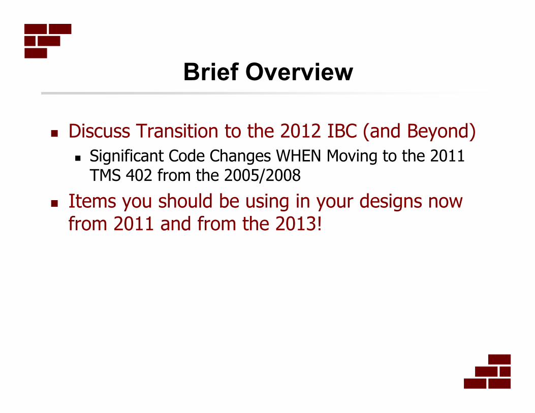
Brief Overview
� Discuss Transition to the 2012 IBC (and Beyond)
� Significant Code Changes WHEN Moving to the 2011 TMS 402 from the 2005/2008
� Items you should be using in your designs now from 2011 and from the 2013!

TMS 402 – 2011 – HERE IT IS!
� 2011 TMS 402 – Building Code
Requirements for Masonry
Structures (TMS 402/ACI 530/ASCE
5) and Commentary - referenced
afterwards as the “Code”
� Specification for Masonry Structures
(TMS 602/ACI 530.1/ASCE 6) and
its Commentary – referenced
afterwards as the “Specification”
� DON’T BUY IT!
4

The “MSJC” Standard
� MSJC or ACI 530? The document is under
the control of TMS as the main body.
� Typically published ever 3 years� IBC 2006 – 2005 TMS 402/602 (MSJC / ACI 530)
� IBC 2009 – 2008 TMS 402/602 (MSJC / ACI 530)
� IBC 2012 – 2011 TMS 402/602 (MSJC / ACI 530)
� IBC 2015 – 2013 TMS 402/602 (MSJC / ACI 530)
� IBC 2018 – 2016 TMS 402/602 (MSJC / ACI 530)
� Why a 2013 Code?? Just getting to 2011…� International Code Council (ICC / IBC) rule changes: Additional time
required to review standards before incorporation into the
International Building Code (IBC).
� 2013 TMS 402/602 was developed in a “shortened cycle” to allow
adoption by the 2015 IBC. Next edition of TMS 402/602 targeted for
2016 to get back on the 3-year revision cycle.
4
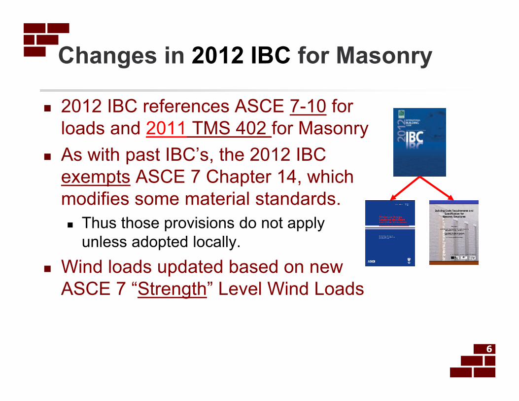
Changes in 2012 IBC for Masonry
� 2012 IBC references ASCE 7-10 for
loads and 2011 TMS 402 for Masonry
� As with past IBC’s, the 2012 IBC
exempts ASCE 7 Chapter 14, which
modifies some material standards.
� Thus those provisions do not apply
unless adopted locally.
� Wind loads updated based on new
ASCE 7 “Strength” Level Wind Loads
6
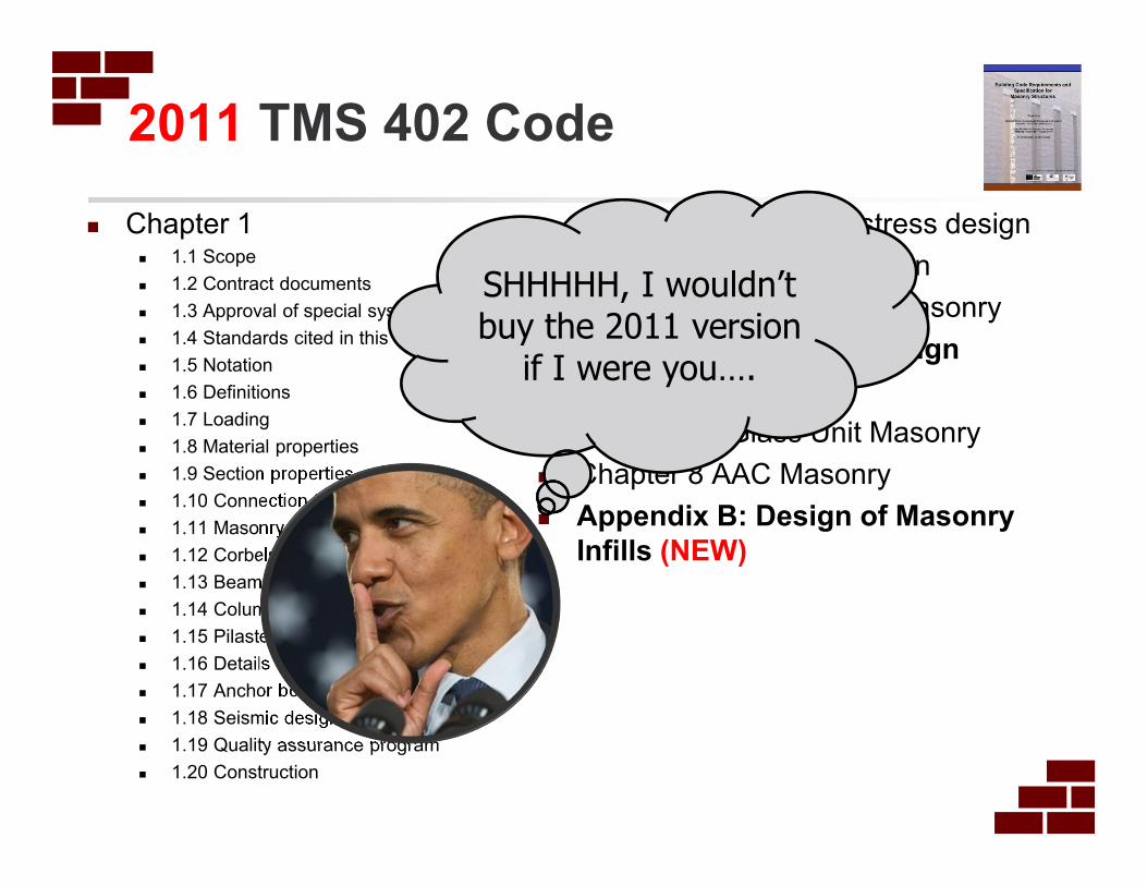
2011 TMS 402 Code
� Chapter 1� 1.1 Scope
� 1.2 Contract documents
� 1.3 Approval of special systems
� 1.4 Standards cited in this Code
� 1.5 Notation
� 1.6 Definitions
� 1.7 Loading
� 1.8 Material properties
� 1.9 Section properties
� 1.10 Connection to structural frames
� 1.11 Masonry not laid in running bond
� 1.12 Corbels
� 1.13 Beams
� 1.14 Columns
� 1.15 Pilasters
� 1.16 Details of reinforcement
� 1.17 Anchor bolts
� 1.18 Seismic design requirements
� 1.19 Quality assurance program
� 1.20 Construction
� Chapter 2: Allowable stress design
� Chapter 3: Strength design
� Chapter 4: Prestressed masonry
� Chapter 5: Empirical design
� Chapter 6: Veneer
� Chapter 7: Glass Unit Masonry
� Chapter 8 AAC Masonry
� Appendix B: Design of Masonry
Infills (NEW)
SHHHHH, I wouldn’t buy the 2011 version
if I were you….
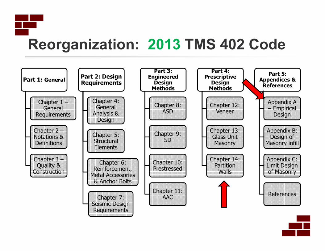
Reorganization: 2013 TMS 402 Code
Part 1: General
Chapter 1 –General
Requirements
Chapter 2 –Notations & Definitions
Chapter 3 –Quality &
Construction
Part 2: Design Requirements
Chapter 4: General
Analysis & Design
Chapter 5: Structural Elements
Chapter 6: Reinforcement,
Metal Accessories & Anchor Bolts
Chapter 7: Seismic Design Requirements
Part 3: Engineered
Design Methods
Chapter 8: ASD
Chapter 9: SD
Chapter 10: Prestressed
Chapter 11: AAC
Part 4: Prescriptive
Design Methods
Chapter 12: Veneer
Chapter 13: Glass Unit Masonry
Chapter 14: Partition
Walls
Part 5: Appendices &
References
Appendix A – Empirical
Design
Appendix B: Design of
Masonry infill
Appendix C: Limit Design of Masonry
References

New Look 2011 TMS 402
� New Side-by-Side
format for the Code
& Commentary and
the Specification &
Commentary for
easier use by users
9
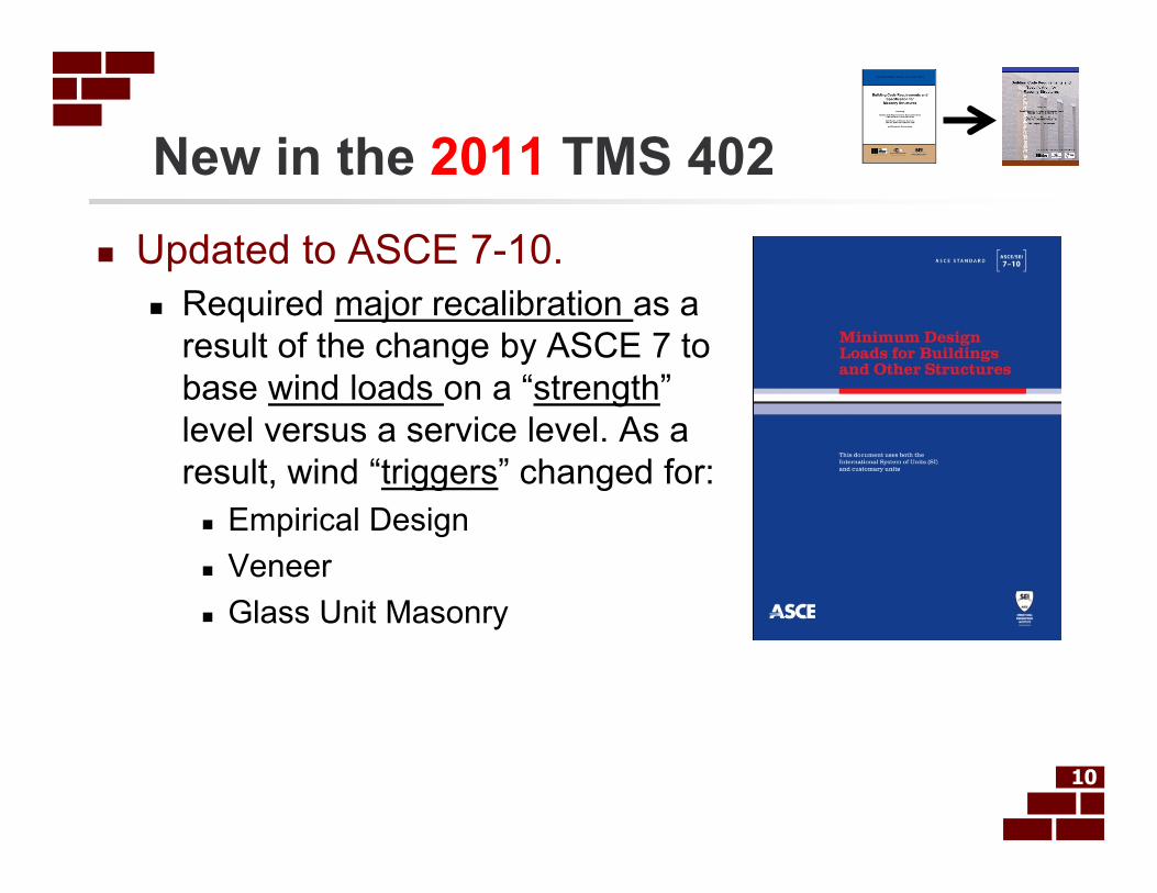
New in the 2011 TMS 402
� Updated to ASCE 7-10.
� Required major recalibration as a
result of the change by ASCE 7 to
base wind loads on a “strength”
level versus a service level. As a
result, wind “triggers” changed for:
� Empirical Design
� Veneer
� Glass Unit Masonry
10

New in the 2011 TMS 402
� Recalibration of Stresses
� Removal of 1/3 stress increase option that was
formerly permitted for Allowable Stress Design
when considering wind or seismic loads (Don’t
worry there are other benefits coming later!)
� Harmonization of ASD and SD shear provisions
� Some Allowable Stresses increased.
� Reduces impact of removal of 1/3 stress increase
� Eliminated the conflict between the TMS 402 -
ASD loading provisions permitting the 1/3 stress
increase and the ASCE 7-05 prohibition of the
1/3 stress increase. 11
2011 Allowable Stresses - General
� Anchor Bolts: No change
� A major Revision took place in 2008 which increased
Allowables; Harmonized with Strength Design
� Bearing Stress
� Increased from 0.25 f′m to 0.33 f′m
� Nominal strength also increased from 0.60 f′mto 0.80 f′m
� Changes based on comparison with other codes
12
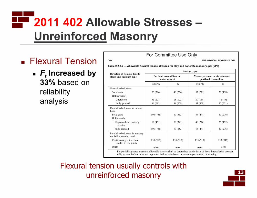
2011 402 Allowable Stresses –
Unreinforced Masonry
� Flexural Tension
� Ft Increased by
33% based on
reliability
analysis
13Flexural tension usually controls with
unreinforced masonry
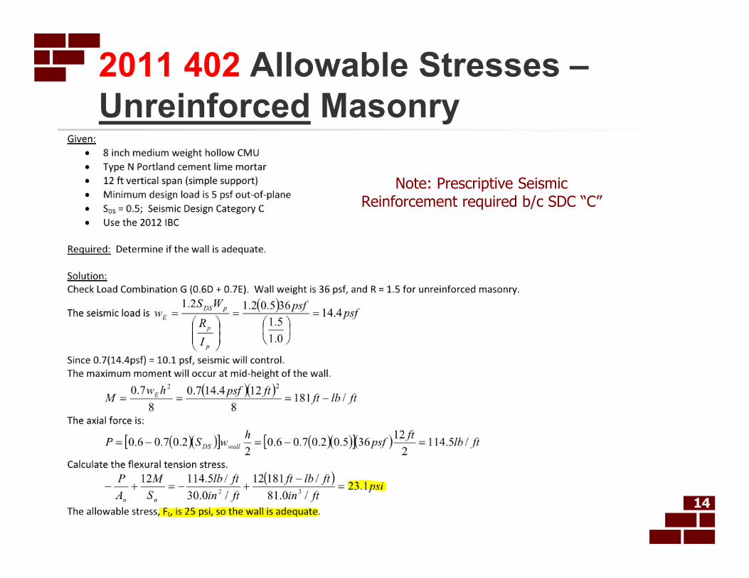
2011 402 Allowable Stresses –
Unreinforced Masonry
14
Note: Prescriptive Seismic Reinforcement required b/c SDC “C”
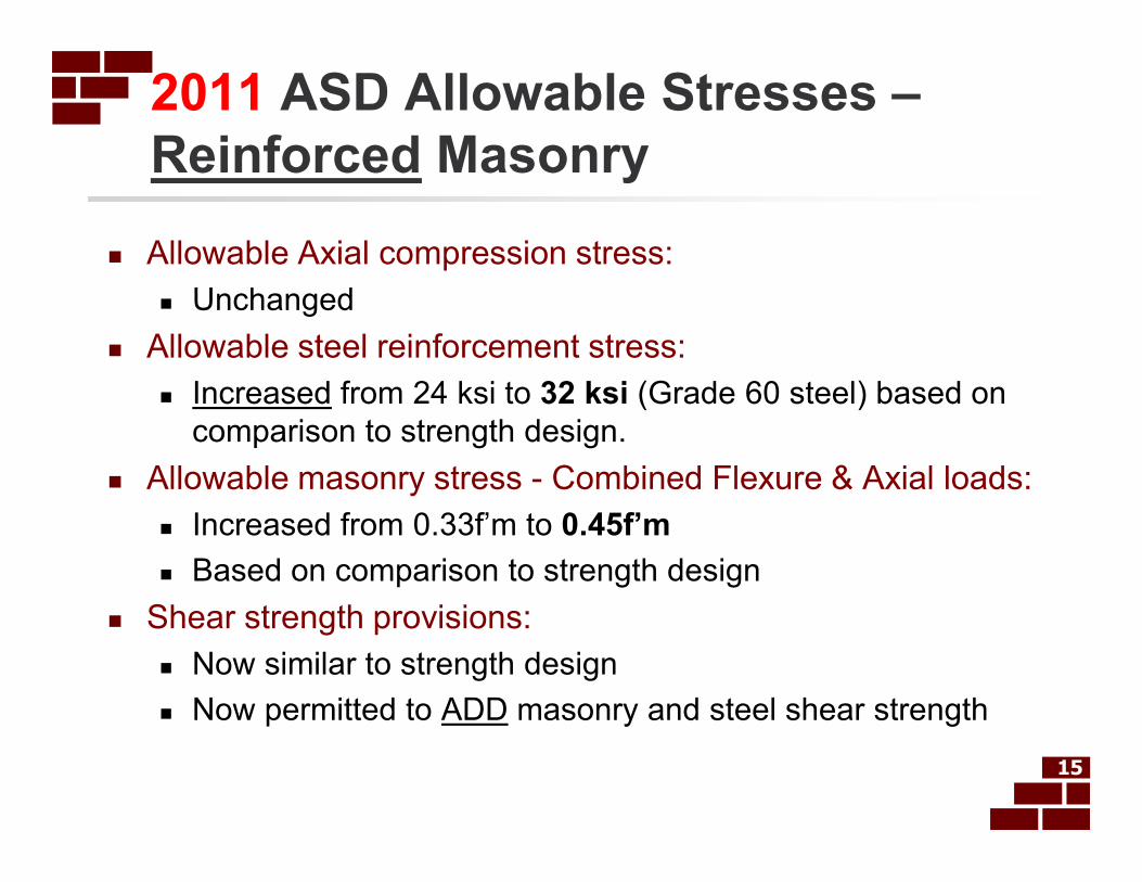
2011 ASD Allowable Stresses –
Reinforced Masonry
� Allowable Axial compression stress:
� Unchanged
� Allowable steel reinforcement stress:
� Increased from 24 ksi to 32 ksi (Grade 60 steel) based on
comparison to strength design.
� Allowable masonry stress - Combined Flexure & Axial loads:
� Increased from 0.33f’m to 0.45f’m
� Based on comparison to strength design
� Shear strength provisions:
� Now similar to strength design
� Now permitted to ADD masonry and steel shear strength
15
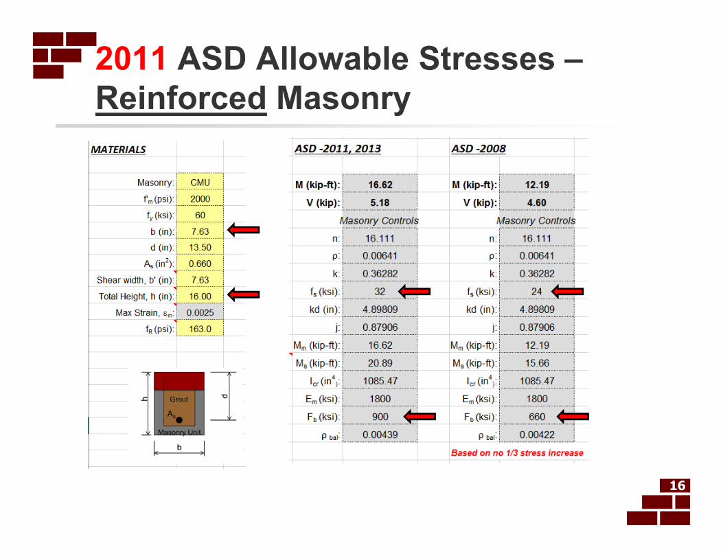
2011 ASD Allowable Stresses –
Reinforced Masonry
16
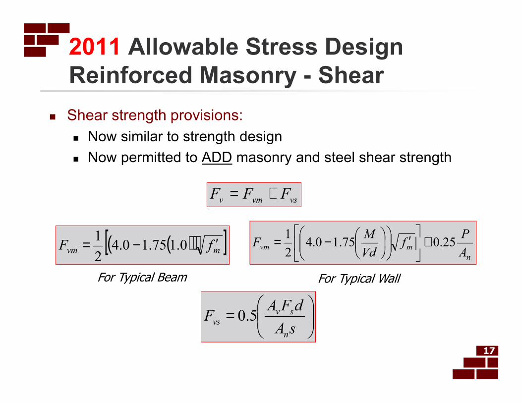
2011 Allowable Stress Design
Reinforced Masonry - Shear
17
vsvmv FFF +=
n
mvmA
Pf
Vd
MF 25.075.10.4
2
1 +
′
−=
=
sA
dFAF
n
svvs 5.0
� Shear strength provisions:
� Now similar to strength design
� Now permitted to ADD masonry and steel shear strength
( )( )[ ]mvm fF ′−= 0.175.10.42
1
For Typical Beam For Typical Wall
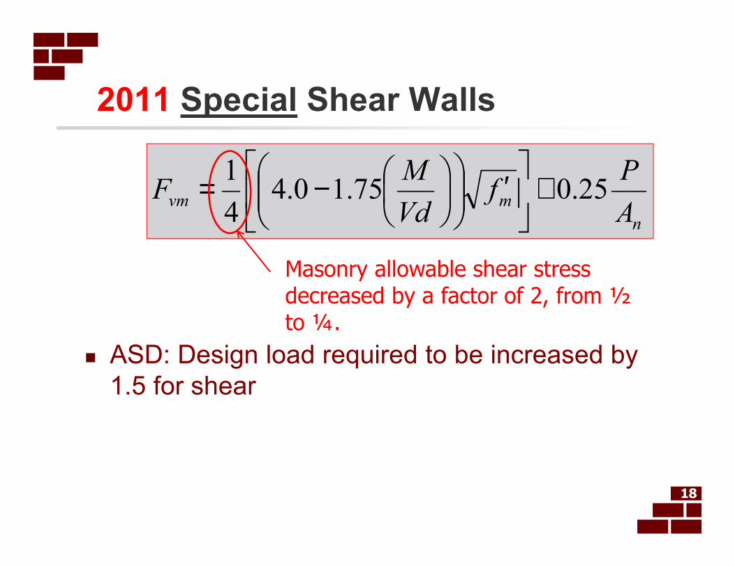
2011 Special Shear Walls
� ASD: Design load required to be increased by
1.5 for shear
18
n
mvmA
Pf
Vd
MF 25.075.10.4
4
1 +
′
−=
Masonry allowable shear stress decreased by a factor of 2, from ½ to ¼.
Impact of 2011 Shear Provisions
� 2011 ASD shear provisions require
approximately the same amount of reinforcement
as strength design provisions
� 2011 ASD shear provisions require significantly
less reinforcement than the 2008 ASD provisions
for ordinary shear walls
� 2011 ASD shear provisions require
approximately the same amount of reinforcement
as the 2008 ASD provisions for special shear
walls19
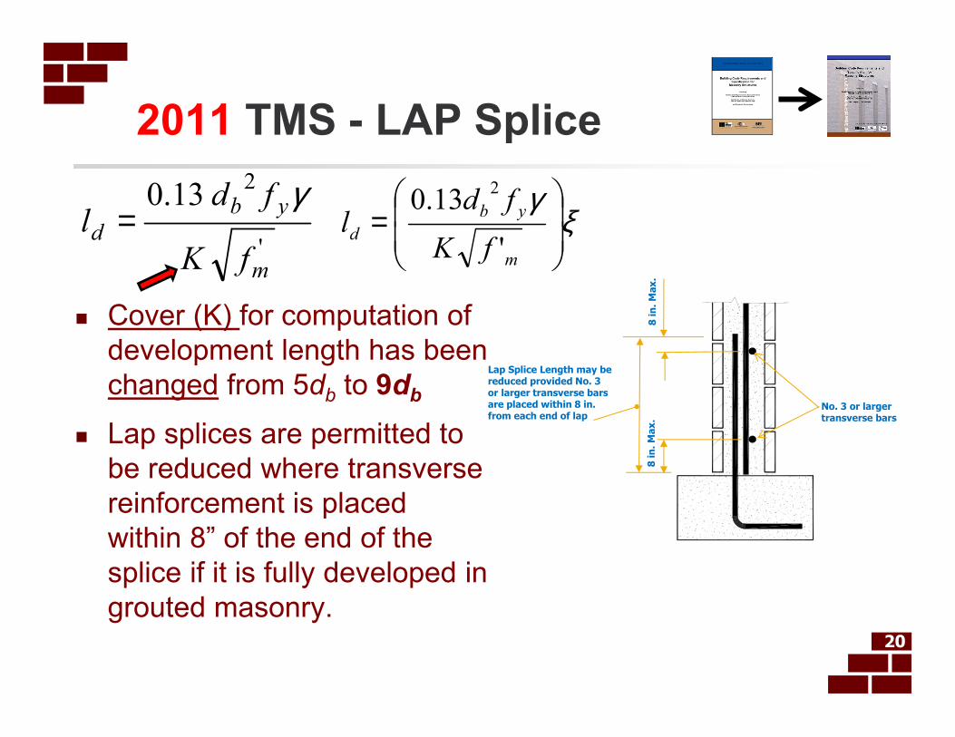
2011 TMS - LAP Splice
20
Lap Splice Length may be reduced provided No. 3 or larger transverse bars are placed within 8 in. from each end of lap
No. 3 or larger transverse bars
8 in
. M
ax
.8
in
. M
ax
.
'
213.0
m
yb
d
fK
fdl
γ= ξ
γ
=
m
yb
dfK
fdl
'
13.02
� Cover (K) for computation of
development length has been
changed from 5db to 9db
� Lap splices are permitted to
be reduced where transverse
reinforcement is placed
within 8” of the end of the
splice if it is fully developed in
grouted masonry.
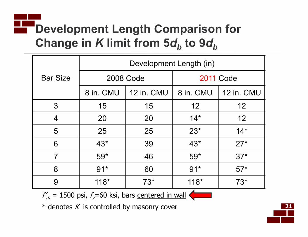
Development Length Comparison for
Change in K limit from 5db
to 9db
21
Bar Size
Development Length (in)
2008 Code 2011 Code
8 in. CMU 12 in. CMU 8 in. CMU 12 in. CMU
3 15 15 12 12
4 20 20 14* 12
5 25 25 23* 14*
6 43* 39 43* 27*
7 59* 46 59* 37*
8 91* 60 91* 57*
9 118* 73* 118* 73*
f’m = 1500 psi, fy=60 ksi, bars centered in wall
* denotes K is controlled by masonry cover
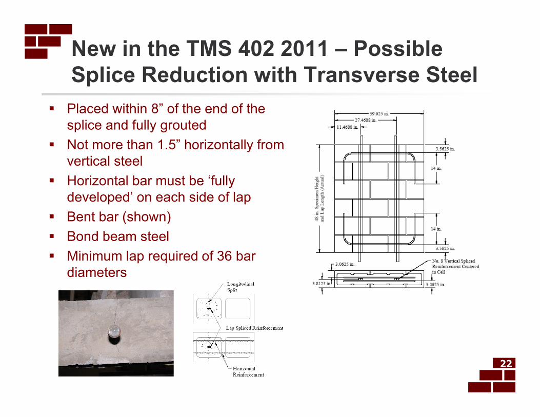
New in the TMS 402 2011 – Possible
Splice Reduction with Transverse Steel
22
� Placed within 8” of the end of the
splice and fully grouted
� Not more than 1.5” horizontally from
vertical steel
� Horizontal bar must be ‘fully
developed’ on each side of lap
� Bent bar (shown)
� Bond beam steel
� Minimum lap required of 36 bar
diameters
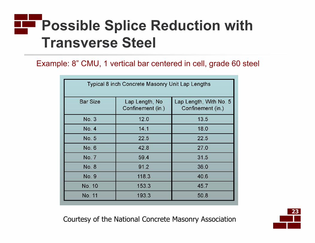
Possible Splice Reduction with
Transverse Steel
Example: 8” CMU, 1 vertical bar centered in cell, grade 60 steel
23
Courtesy of the National Concrete Masonry Association

New in the 2011 TMS 402
� Deep Beam Provisions
added. Apply to beams where
the effective span-to-depth
ratio, Leff /dv is less than:
� 3 for continuous span
� 2 for simple span
24
� Requires additional analysis as well as
minimum flexural and shear reinforcement
(Code Section 1.13.2)
Leff per 1.13.1
dv

Deep Beam Clarification (2013) 5.2.2 Commentary
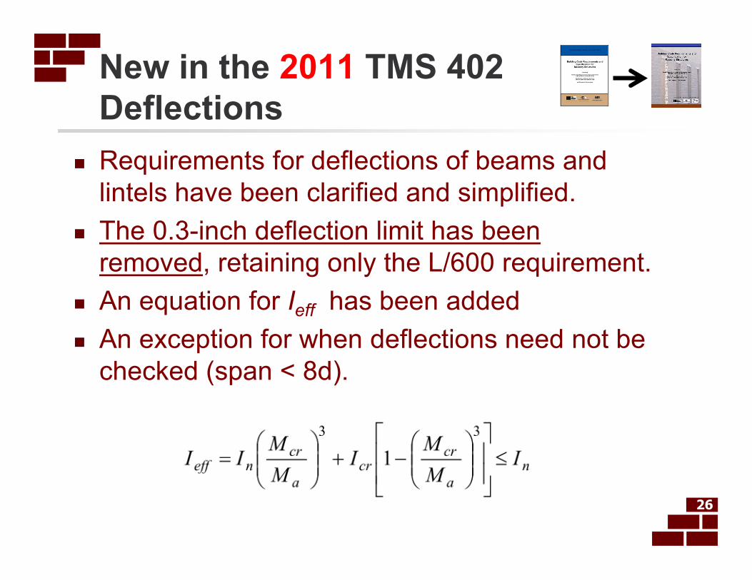
New in the 2011 TMS 402
Deflections
� Requirements for deflections of beams and
lintels have been clarified and simplified.
� The 0.3-inch deflection limit has been
removed, retaining only the L/600 requirement.
� An equation for Ieff has been added
� An exception for when deflections need not be
checked (span < 8d).
26
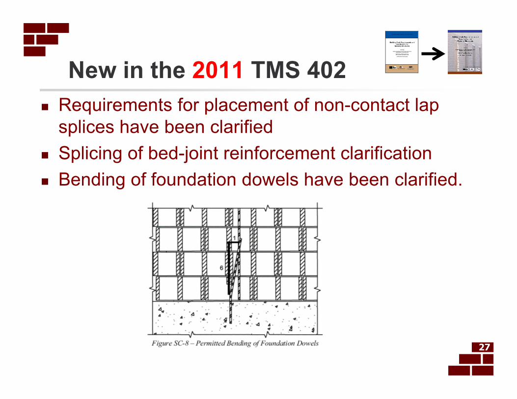
New in the 2011 TMS 402
� Requirements for placement of non-contact lap
splices have been clarified
� Splicing of bed-joint reinforcement clarification
� Bending of foundation dowels have been clarified.
27
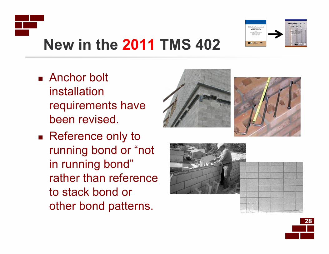
New in the 2011 TMS 402
� Anchor bolt
installation
requirements have
been revised.
� Reference only to
running bond or “not
in running bond”
rather than reference
to stack bond or
other bond patterns.28

2012 IBC Special Inspection
� Special Inspection
Tables for Masonry have
been deleted from IBC
Chapter 17, and it now
simply references the
2011 TMS 402 Quality
Assurance Tables
29
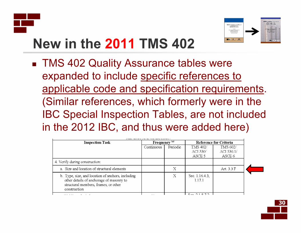
New in the 2011 TMS 402
� TMS 402 Quality Assurance tables were
expanded to include specific references to
applicable code and specification requirements.
(Similar references, which formerly were in the
IBC Special Inspection Tables, are not included
in the 2012 IBC, and thus were added here)
30
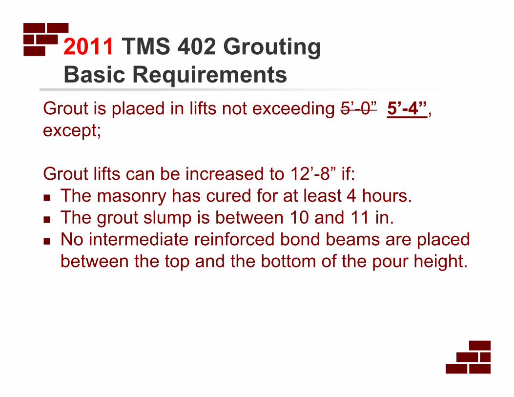
2011 TMS 402 Grouting
Basic Requirements
Grout is placed in lifts not exceeding 5’-0” 5’-4”,
except;
Grout lifts can be increased to 12’-8” if:
� The masonry has cured for at least 4 hours.
� The grout slump is between 10 and 11 in.
� No intermediate reinforced bond beams are placed
between the top and the bottom of the pour height.
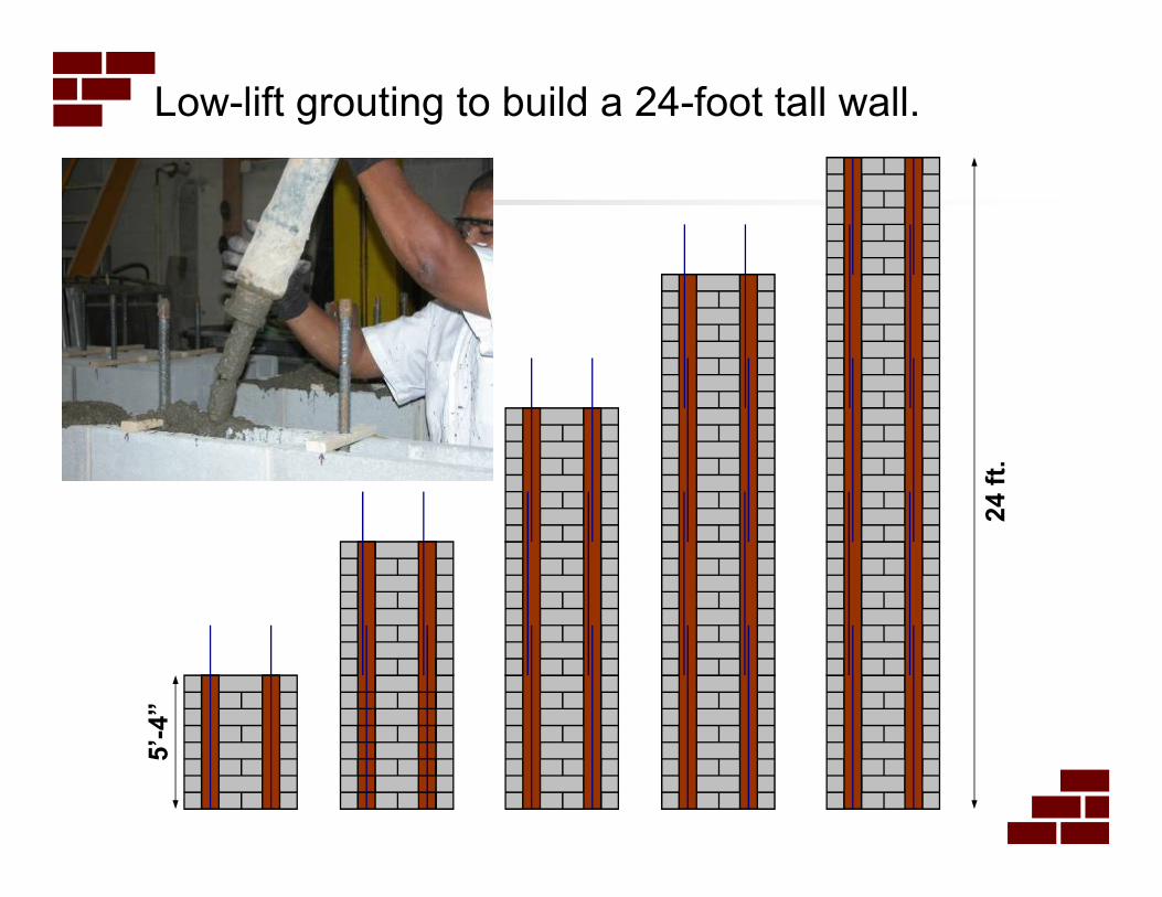
Low-lift grouting to build a 24-foot tall wall.
5’-
4”
24 f
t.
24 f
t.
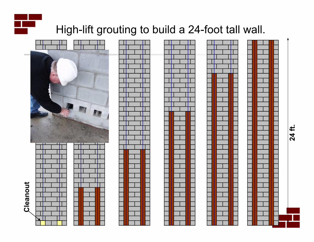
High-lift grouting to build a 24-foot tall wall.C
lean
ou
t
24 f
t.
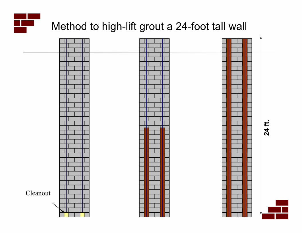
Method to high-lift grout a 24-foot tall wall
Cleanout
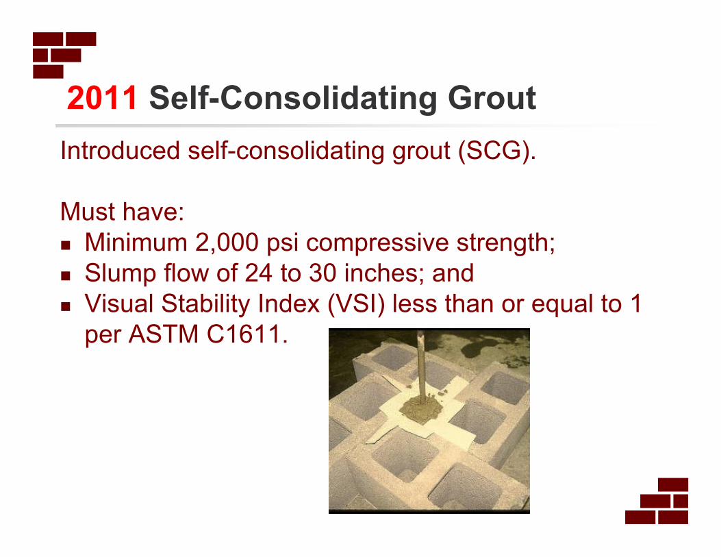
2011 Self-Consolidating Grout
Introduced self-consolidating grout (SCG).
Must have:
� Minimum 2,000 psi compressive strength;
� Slump flow of 24 to 30 inches; and
� Visual Stability Index (VSI) less than or equal to 1
per ASTM C1611.
36
PARTITIONS
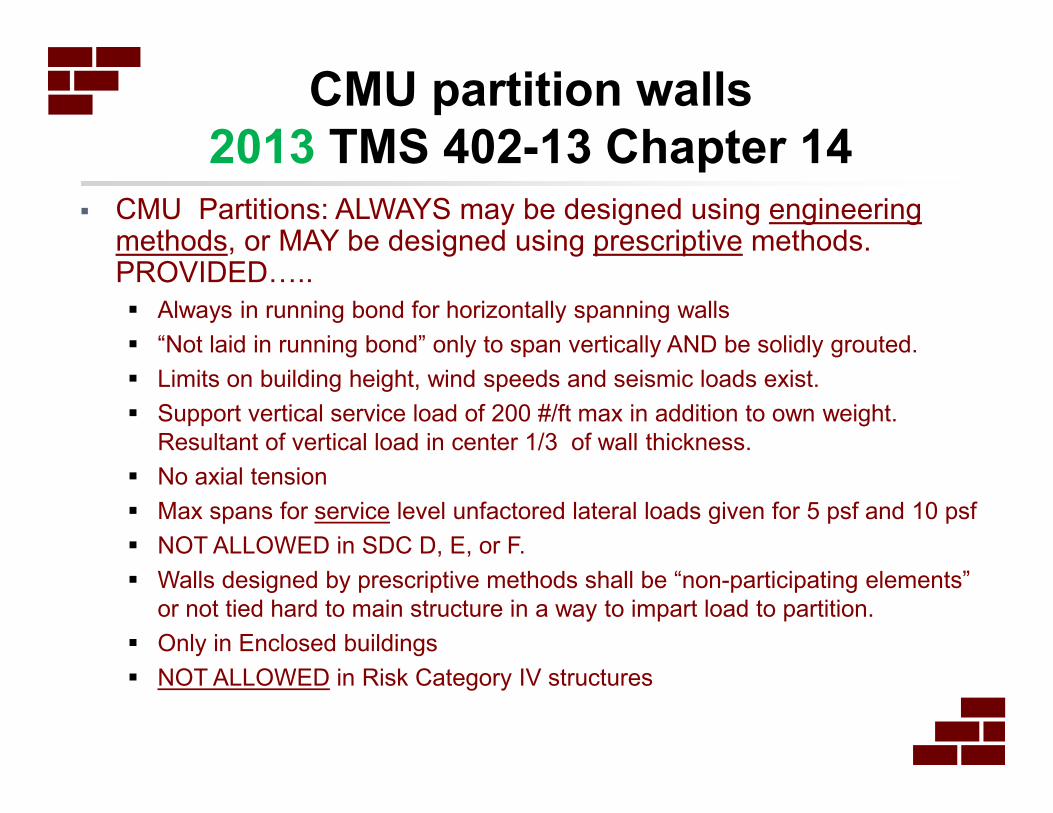
CMU partition walls
2013 TMS 402-13 Chapter 14� CMU Partitions: ALWAYS may be designed using engineering
methods, or MAY be designed using prescriptive methods. PROVIDED…..
� Always in running bond for horizontally spanning walls
� “Not laid in running bond” only to span vertically AND be solidly grouted.
� Limits on building height, wind speeds and seismic loads exist.
� Support vertical service load of 200 #/ft max in addition to own weight.
Resultant of vertical load in center 1/3 of wall thickness.
� No axial tension
� Max spans for service level unfactored lateral loads given for 5 psf and 10 psf
� NOT ALLOWED in SDC D, E, or F.
� Walls designed by prescriptive methods shall be “non-participating elements”
or not tied hard to main structure in a way to impart load to partition.
� Only in Enclosed buildings
� NOT ALLOWED in Risk Category IV structures
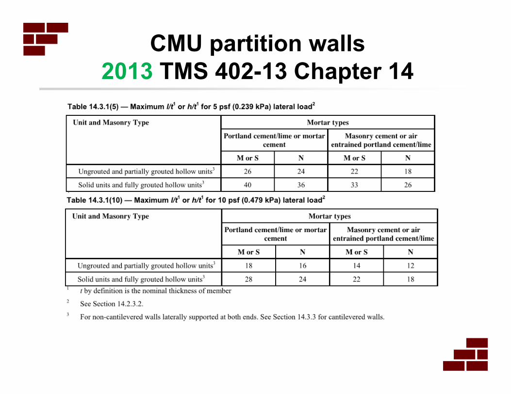
CMU partition walls
2013 TMS 402-13 Chapter 14
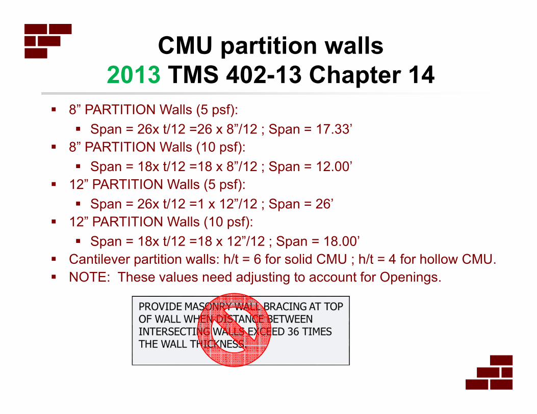
� 8” PARTITION Walls (5 psf):
� Span = 26x t/12 =26 x 8”/12 ; Span = 17.33’
� 8” PARTITION Walls (10 psf):
� Span = 18x t/12 =18 x 8”/12 ; Span = 12.00’
� 12” PARTITION Walls (5 psf):
� Span = 26x t/12 =1 x 12”/12 ; Span = 26’
� 12” PARTITION Walls (10 psf):
� Span = 18x t/12 =18 x 12”/12 ; Span = 18.00’
� Cantilever partition walls: h/t = 6 for solid CMU ; h/t = 4 for hollow CMU.
� NOTE: These values need adjusting to account for Openings.
CMU partition walls
2013 TMS 402-13 Chapter 14
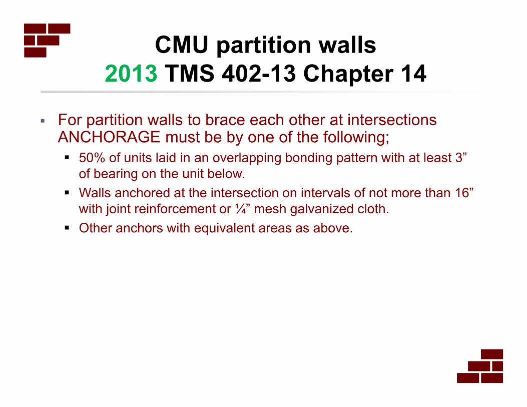
� For partition walls to brace each other at intersections ANCHORAGE must be by one of the following;
� 50% of units laid in an overlapping bonding pattern with at least 3”
of bearing on the unit below.
� Walls anchored at the intersection on intervals of not more than 16”
with joint reinforcement or ¼” mesh galvanized cloth.
� Other anchors with equivalent areas as above.
CMU partition walls
2013 TMS 402-13 Chapter 14
41
F’m
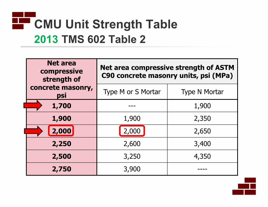
CMU Unit Strength Table
2013 TMS 602 Table 2
Net area compressive strength of
concrete masonry, psi
Net area compressive strength of ASTM C90 concrete masonry units, psi (MPa)
Type M or S Mortar Type N Mortar
1,700 --- 1,900
1,900 1,900 2,350
2,000 2,000 2,650
2,250 2,600 3,400
2,500 3,250 4,350
2,750 3,900 ----
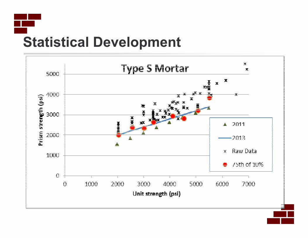
Statistical Development
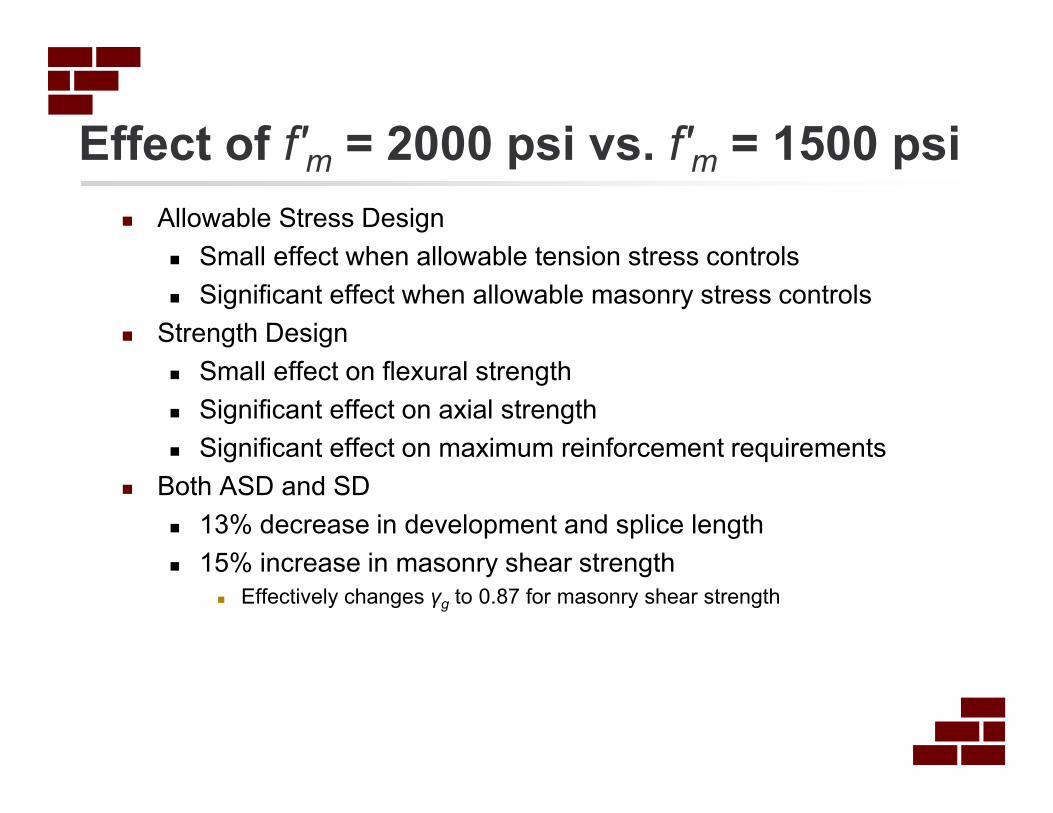
Effect of f′m = 2000 psi vs. f′m = 1500 psi
� Allowable Stress Design
� Small effect when allowable tension stress controls
� Significant effect when allowable masonry stress controls
� Strength Design
� Small effect on flexural strength
� Significant effect on axial strength
� Significant effect on maximum reinforcement requirements
� Both ASD and SD
� 13% decrease in development and splice length
� 15% increase in masonry shear strength
� Effectively changes γg to 0.87 for masonry shear strength
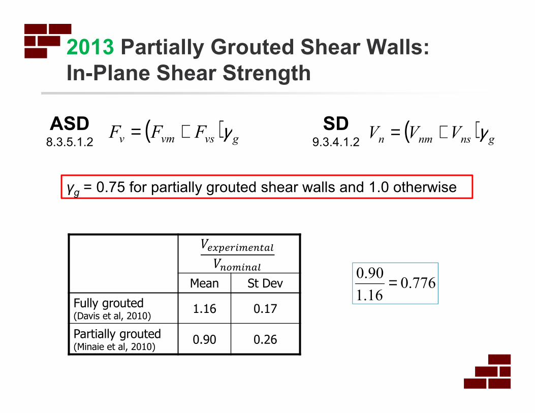
2013 Partially Grouted Shear Walls:
In-Plane Shear Strength
�����������
�������
Mean St Dev
Fully grouted(Davis et al, 2010)
1.16 0.17
Partially grouted(Minaie et al, 2010)
0.90 0.26
776.016.1
90.0 =
( ) gvsvmv FFF γ+=ASD8.3.5.1.2
SD9.3.4.1.2
( ) gnsnmn VVV γ+=
γg = 0.75 for partially grouted shear walls and 1.0 otherwise
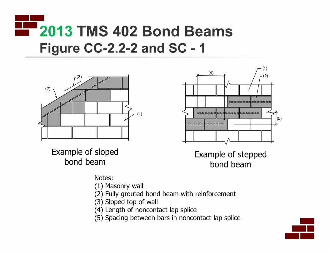
2013 TMS 402 Bond BeamsFigure CC-2.2-2 and SC - 1
3)(
(2)
1)(
4)((2)
1)(
(5)
Example of sloped bond beam
Example of stepped bond beam
Notes:(1) Masonry wall(2) Fully grouted bond beam with reinforcement(3) Sloped top of wall(4) Length of noncontact lap splice(5) Spacing between bars in noncontact lap splice
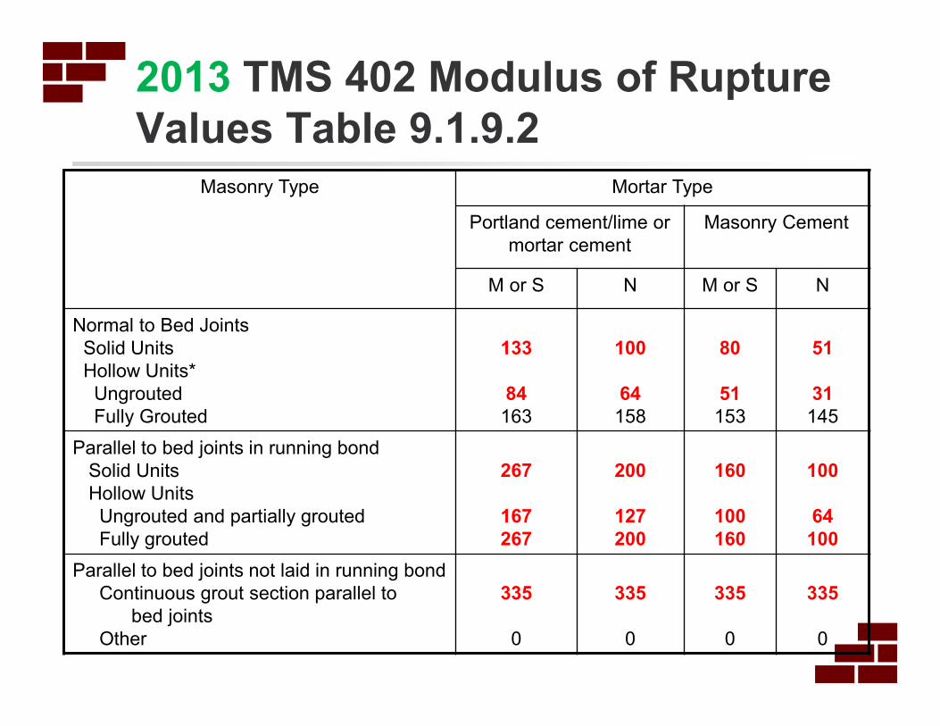
2013 TMS 402 Modulus of Rupture
Values Table 9.1.9.2
Masonry Type Mortar Type
Portland cement/lime or
mortar cement
Masonry Cement
M or S N M or S N
Normal to Bed Joints
Solid Units
Hollow Units*
Ungrouted
Fully Grouted
133
84
163
100
64
158
80
51
153
51
31
145
Parallel to bed joints in running bond
Solid Units
Hollow Units
Ungrouted and partially grouted
Fully grouted
267
167
267
200
127
200
160
100
160
100
64
100
Parallel to bed joints not laid in running bond
Continuous grout section parallel to
bed joints
Other
335
0
335
0
335
0
335
0

2013 Modulus of Rupture:
Effect of Increase
2011:
2013:
( ) psicells
cellgroutedpsi
cells
cellsungroutedpsifr 57
6
1153
6
538 =
+
=
Example: 8 inch CMU, bars at 48 inch, Type S masonry cement
( ) psicells
cellgroutedpsi
cells
cellsungroutedpsifr 68
6
1153
6
551 =
+
=
Load Combination δ (inch)
fr = 57 psi fr = 68 psi
D+0.6W 0.70 0.55
0.6D+0.6W 0.65 0.50
D+0.75(0.6W)+0.75Lr 0.38 0.22
Results from 18 ft high bearing wall trial design: out-of-plane loads
Primary impact is to reduce calculated deflections under out-of-plane loading
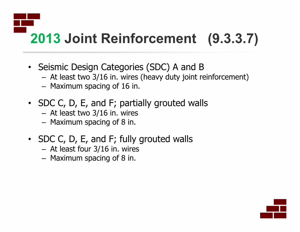
2013 Joint Reinforcement (9.3.3.7)
• Seismic Design Categories (SDC) A and B– At least two 3/16 in. wires (heavy duty joint reinforcement)– Maximum spacing of 16 in.
• SDC C, D, E, and F; partially grouted walls– At least two 3/16 in. wires– Maximum spacing of 8 in.
• SDC C, D, E, and F; fully grouted walls– At least four 3/16 in. wires– Maximum spacing of 8 in.

2013 Joint ReinforcementEquivalent Reinforcement Options
Joint ReinforcementEquivalent Bar
Reinforcement
Replaces this
Reinforcement
2 - 3/16 in. wires at 16 in. 0.0347 in2/ft #4 @ 56in.; #5 @ 80 in.
2 – 3/16 in. wires at 8 in. 0.0694 in2/ft #4 @ 32 in.; #5 @ 40 in.
4 – 3/16 in. wires at 8 in. 0.1388 in2/ft #4 @ 16 in.; #5 @ 24 in.
Bar reinforcement yield stress = 60 ksiJoint reinforcement yield stress = 70 ksi
Splice length: 48db (9.3.3.4 (e))
Anchor around edge reinforcing bar, either by bar placement between adjacent cross-wires or with a 90° bend in longitudinal wires and at least 3-in. bend extensions. (9.3.3.3.2.3)
2013 Reinforcement and Mortar
Reinforcement
• Mechanical splices in flexural reinforcement in plastic hinge zones of special reinforced walls: required to develop the specified tensile strength of the spliced bar, rather than 1.25fy (7.3.2.6 (e))
• Welded splices: reinforcement required to either conform to ASTM A706, or a chemical analysis and carbon equivalent of the reinforcement steel will need to be determined. (8.1.6.7.2, 9.3.3.4 (c))
Mortar
• Masonry cement mortar is now permitted for fully grouted participating elements in Seismic Design Category (SDC) D and higher. (7.4.4.2.2)
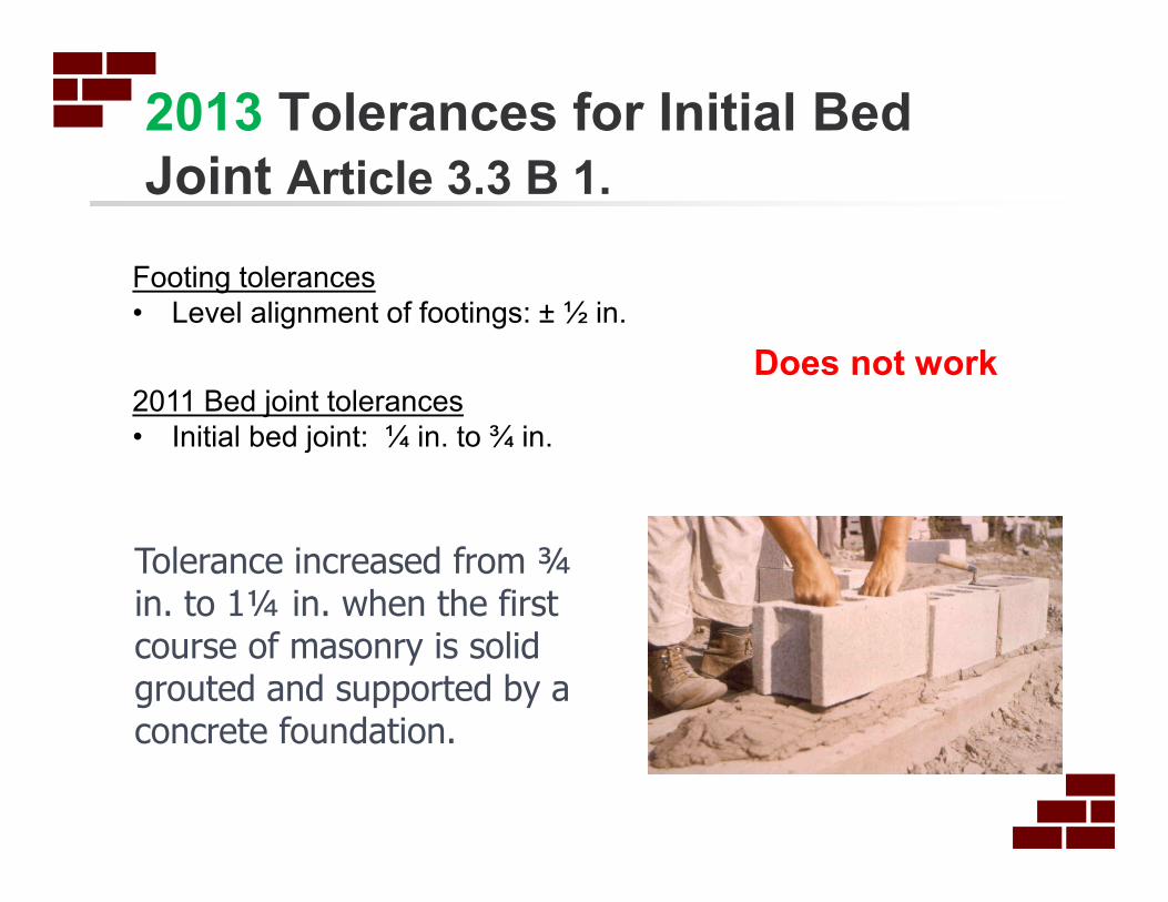
2013 Tolerances for Initial Bed
Joint Article 3.3 B 1.
Tolerance increased from ¾ in. to 1¼ in. when the first course of masonry is solid grouted and supported by a concrete foundation.
Footing tolerances
• Level alignment of footings: ± ½ in.
2011 Bed joint tolerances
• Initial bed joint: ¼ in. to ¾ in.
Does not work
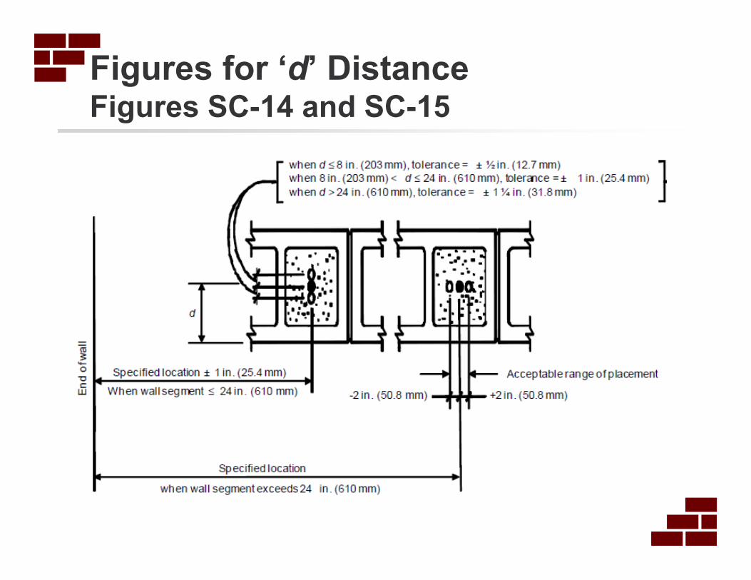
Figures for ‘d’ DistanceFigures SC-14 and SC-15

54
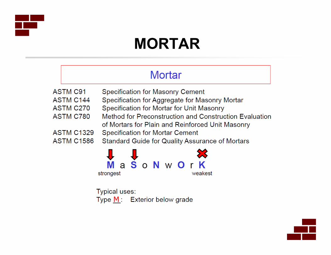
MORTAR
MORTAR
M

MORTAR Confusion
� What is the minimum required compressive strength for masonry mortars? We often get Low Mortar tests.
� Simply put, there are NO minimum compressive strength requirements for field-batched masonry mortar in any current ASTM or building code.
� There are, however, minimum compressive strength requirements for mortars prepared and tested in the laboratory (ASTM C270).
� TWO Primary ASTM testing for Masonry Mortar:
� ASTM C270 Standard Specification for Mortar for Unit Masonry
� ASTM C780 Standard test Method for Preconstruction and Construction Evaluation of Mortars for Plan and Reinforced Unit Masonry
� ASTM C780: Section 5.2.6 states “………The measured value shall not, however, be construed as being representative of the actual strength of the mortar in the masonry.
� ASTM C270: Section 3.1 “Specification C 270 is NOT a specification to determine mortar strengths through field testing. (ie, only applies to lab prepared mortar)
� In practice, the compressive strength requirements for masonry mortar contained in ASTM C270 are often misapplied to field-batched mortar.
2013 ASTM C90:
Normalized Web Area
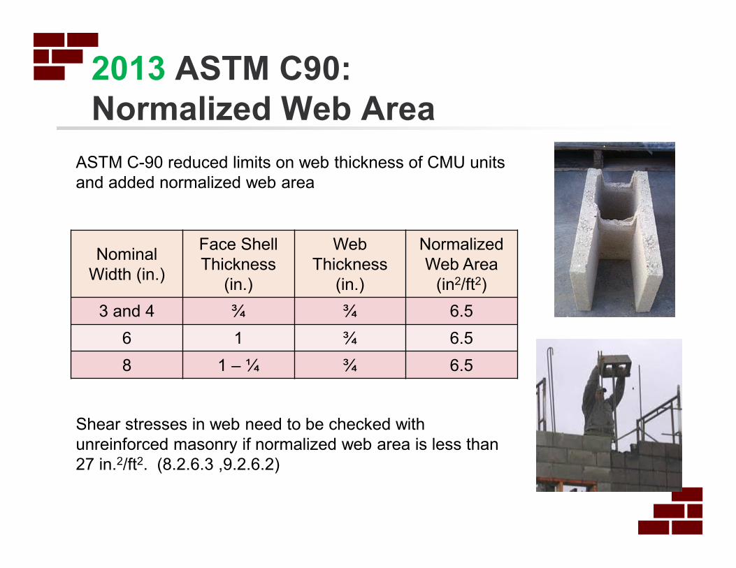
ASTM C-90 reduced limits on web thickness of CMU units
and added normalized web area
Nominal
Width (in.)
Face Shell
Thickness
(in.)
Web
Thickness
(in.)
Normalized
Web Area
(in2/ft2)
3 and 4 ¾ ¾ 6.5
6 1 ¾ 6.5
8 1 – ¼ ¾ 6.5
Shear stresses in web need to be checked with
unreinforced masonry if normalized web area is less than
27 in.2/ft2. (8.2.6.3 ,9.2.6.2)
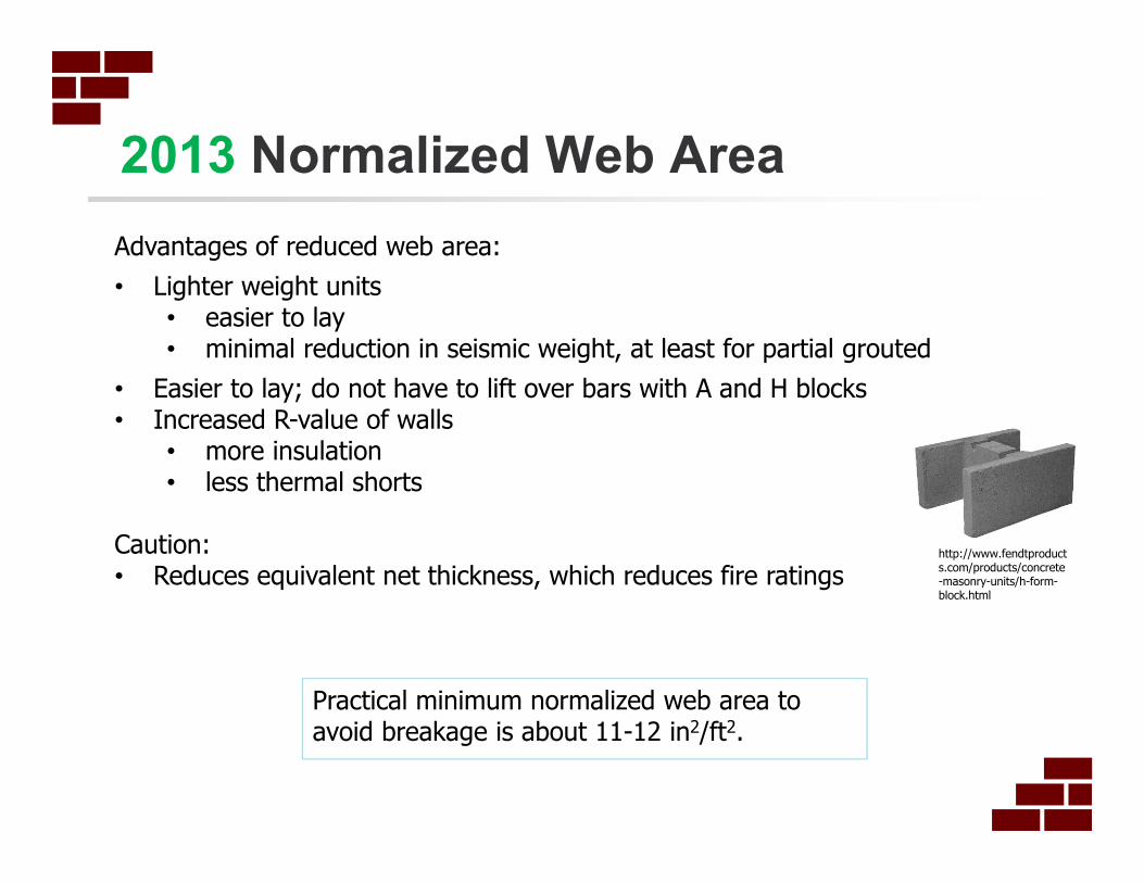
2013 Normalized Web Area
Advantages of reduced web area:
• Lighter weight units• easier to lay• minimal reduction in seismic weight, at least for partial grouted
• Easier to lay; do not have to lift over bars with A and H blocks• Increased R-value of walls
• more insulation• less thermal shorts
Caution:• Reduces equivalent net thickness, which reduces fire ratings
http://www.fendtproducts.com/products/concrete-masonry-units/h-form-block.html
Practical minimum normalized web area to avoid breakage is about 11-12 in2/ft2.

Example: Normalized Web Area
Given:• 8 ft high unreinforced 8 inch CMU wall• Type S PCL mortar; face shell bedding• Factored wind load of 46 psf• Flexural tensile stress = 32.7 psi; allowable = 33 psi
Required: Check shear stress in webs for a unit with a single center web that is 1.25 in. thick and 4-5/8 in. high.
Solution: From ASTM C90, find normalized web area
( )( )( )( )
( )( )22
/.5.6144.8.16
.63.4.25.1144 ftin
inin
inin
HL
AA
nn
wtwn =×=×=
Awn - normalized web areaAwt - minimum web areaLn - nominal length of unitHn - nominal height of the unit
This is minimum normalized web area; most block will have at least twice this area.
Example: Normalized Web Area
OK
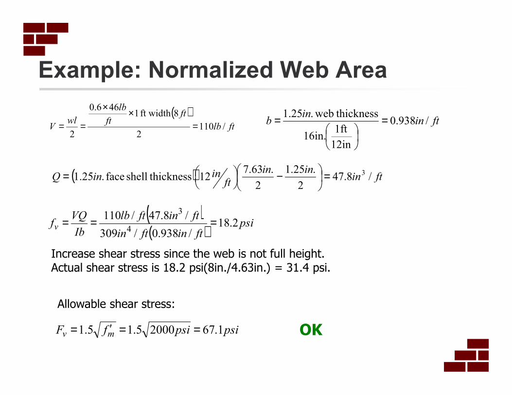
( )ftlb
ftft
lb
wlV /110
2
8ft width 1 466.0
2=
××
==
( ) ftininin
ftininQ /8.47
2
.25.1
2
.63.712 thicknessshell face .25.1
3=
−
=
ftinin
b /938.0
12in
1ft16in.
thickness web.25.1 =
=
( )( )
psiftinftin
ftinftlb
Ib
VQfv 2.18
/938.0/309
/8.47/110
4
3
===
Increase shear stress since the web is not full height.Actual shear stress is 18.2 psi(8in./4.63in.) = 31.4 psi.
psipsifF mv 1.6720005.15.1 ==′=
Allowable shear stress:
![Engineering Notes for Design with Concrete Block Masonry … · 2021. 5. 19. · for Masonry Structures [TMS 402-13] and the corresponding Specification [TMS 602-13] along with the](https://static.fdocuments.in/doc/165x107/6146621d7599b83a5f002fb3/engineering-notes-for-design-with-concrete-block-masonry-2021-5-19-for-masonry.jpg)