
Concrete Filled Steel Tube Bridge Pier Connections - An ABC Solution
57
Concrete Filled Steel Tube Bridge Pier Connections - An ABC Solution Bijan Khaleghi State Bridge Design Engineer WSDOT Dawn Lehman Professor, University of Washington Charles Roeder Professor, University of Washington
Transcript of Concrete Filled Steel Tube Bridge Pier Connections - An ABC Solution
Concrete Filled Steel Tube Bridge Pier Connections - An ABC Solution
Bijan Khaleghi State Bridge Design Engineer WSDOT
Dawn Lehman Professor, University of
Washington
Charles Roeder Professor, University of
Washington
Presentation Outline • Advantages of CFT for ABC • CFT Design and Construction • Concerns and Need for Research
• UW Research on CFST
Bridges for ABC • Flexural and Shear Design Expressions • Advantages of CFT for Seismic Applications • CFT to Cap and Footing Connections • CFT Implementation and Projects
Date, time and initials of last edit 2
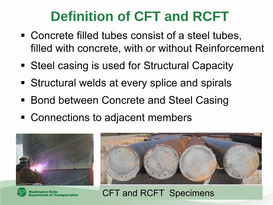
Definition of CFT and RCFT Concrete filled tubes consist of a steel tubes,
filled with concrete, with or without Reinforcement Steel casing is used for Structural Capacity Structural welds at every splice and spirals Bond between Concrete and Steel Casing Connections to adjacent members
CFT and RCFT Specimens
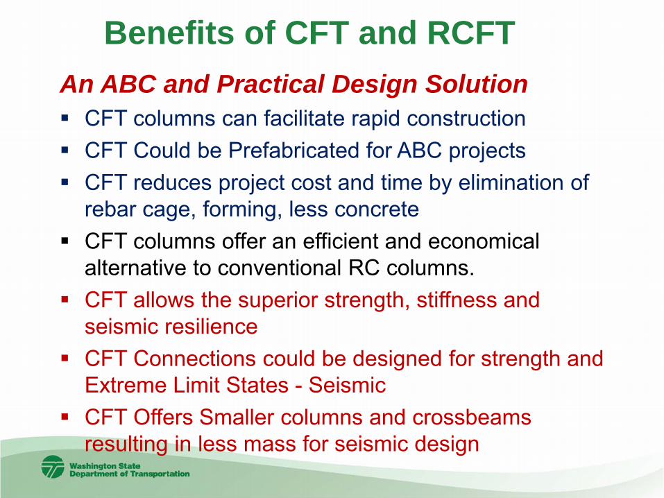
An ABC and Practical Design Solution CFT columns can facilitate rapid construction CFT Could be Prefabricated for ABC projects CFT reduces project cost and time by elimination of
rebar cage, forming, less concrete CFT columns offer an efficient and economical
alternative to conventional RC columns. CFT allows the superior strength, stiffness and
seismic resilience CFT Connections could be designed for strength and
Extreme Limit States - Seismic CFT Offers Smaller columns and crossbeams
resulting in less mass for seismic design
Benefits of CFT and RCFT

CFT- An ABC & Practical Design Solution
Date, time and initials of last edit 5
CFT eliminate the need for reinforcing steel and forming Reduce construction time and cost CFT Offers Smaller columns and crossbeams resulting
in less mass for seismic design

Challenges with CFT – Need for Research
• Lack of Design Guidance for Axial, Flexural and Shear Strength for CFT and RCFT
• Account for Strength and stiffness of steel casing in the analysis and design
• Connections to Pier Cap and Foundation for Strength and Extreme Limit States
• CFT & RCFT Embedment into Cap/Foundation • Bond between concrete and steel casing • Long term performance and longevity of CFT

Design Consideration: Lateral Loads
Ductility
Deep Foundation Lateral EQ Load
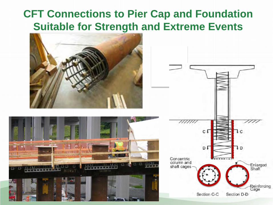
CFT Connections to Pier Cap and Foundation Suitable for Strength and Extreme Events
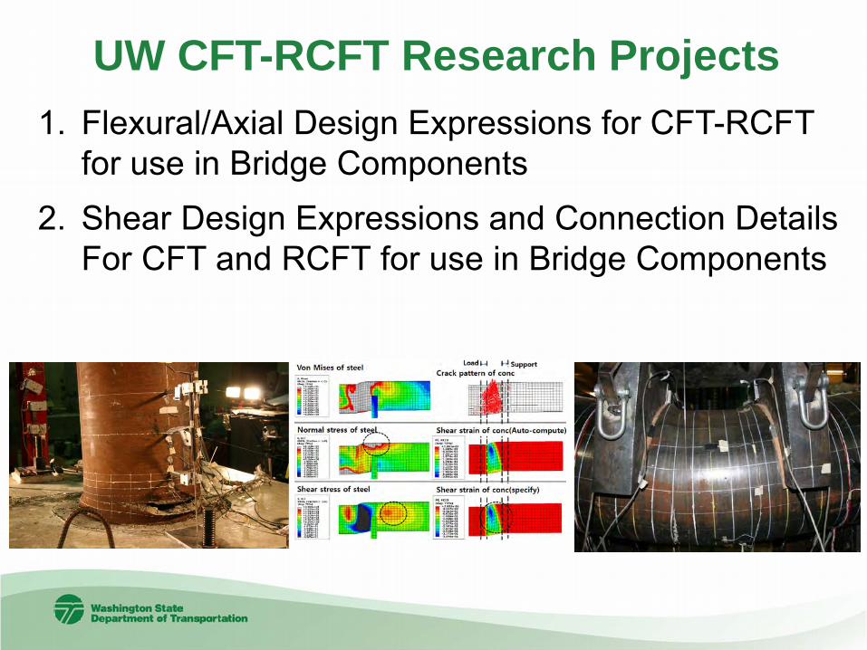
1. Flexural/Axial Design Expressions for CFT-RCFT for use in Bridge Components
2. Shear Design Expressions and Connection Details For CFT and RCFT for use in Bridge Components
UW CFT-RCFT Research Projects

Research on CFST Bridges for ABC
Professor Dawn Lehman & Professor Charles Roeder Max Stephens (Graduate Student Researcher) University of Washington
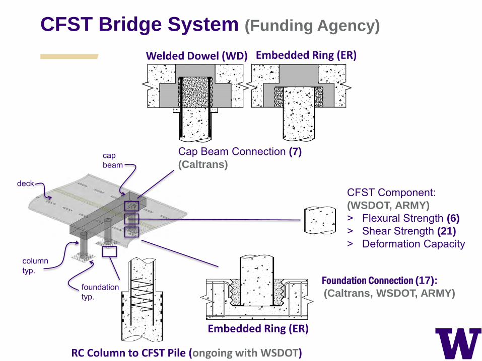
CFST Bridge System (Funding Agency)
CFST Component: (WSDOT, ARMY) ˃ Flexural Strength (6) ˃ Shear Strength (21) ˃ Deformation Capacity
Foundation Connection (17): (Caltrans, WSDOT, ARMY)
cap beam
column typ.
deck
foundation typ.
Cap Beam Connection (7) (Caltrans)
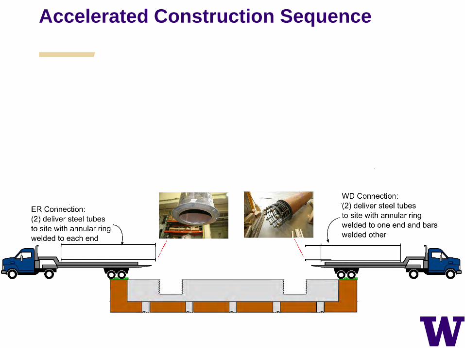
Welded Dowel (WD) Embedded Ring (ER)
Embedded Ring (ER)
RC Column to CFST Pile (ongoing with WSDOT)

Application of CFST to ABC
> Relative to RC construction – No formwork to construct,
tear down or store – Internal reinforcement not
required – Self-consolidating concrete – Smaller diameters than RC
columns > Relative to precast
– Lighter than precast columns; facilitate placement
– Length and diameters can easily vary within a structure
– Can be integrated with precast components including cap beams.
Photo Courtesy of MDT
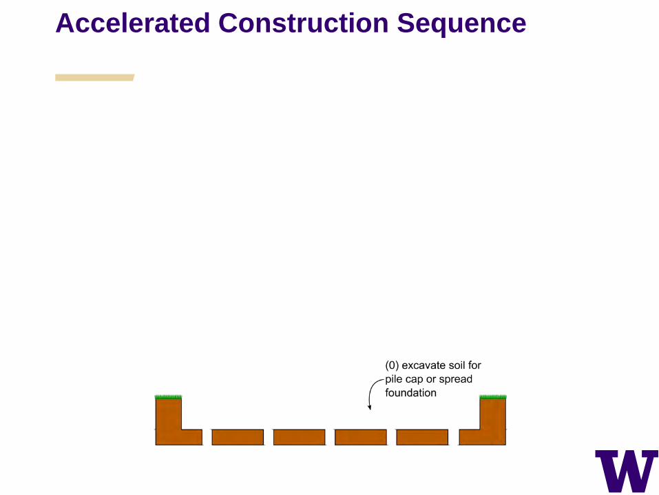
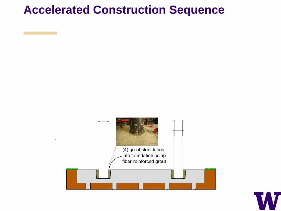
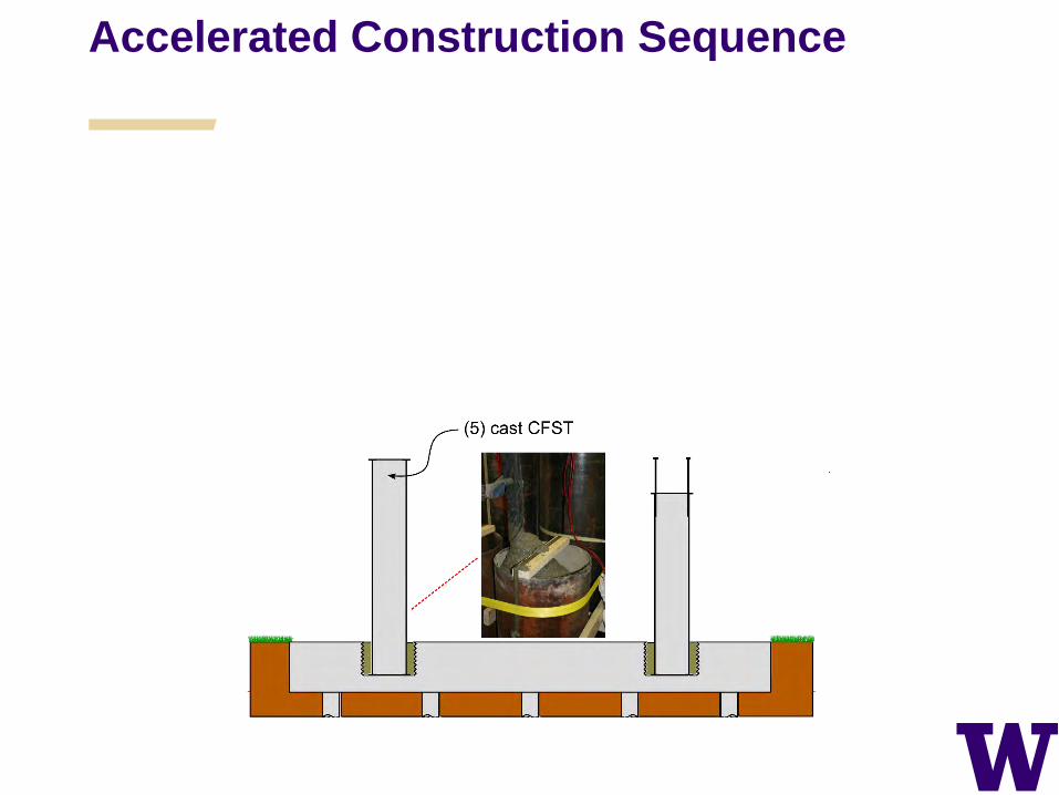
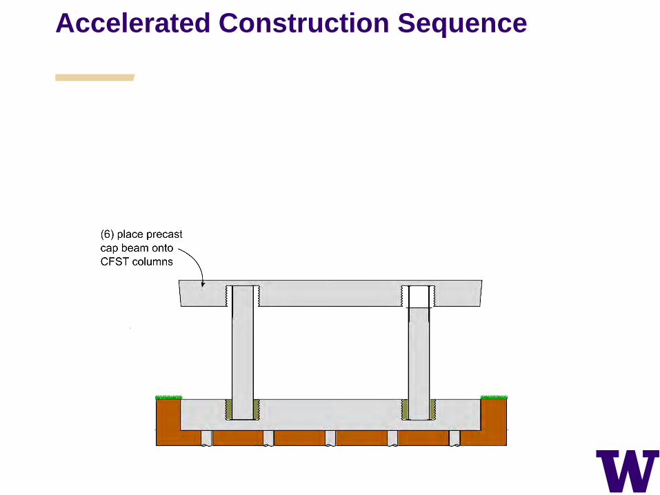
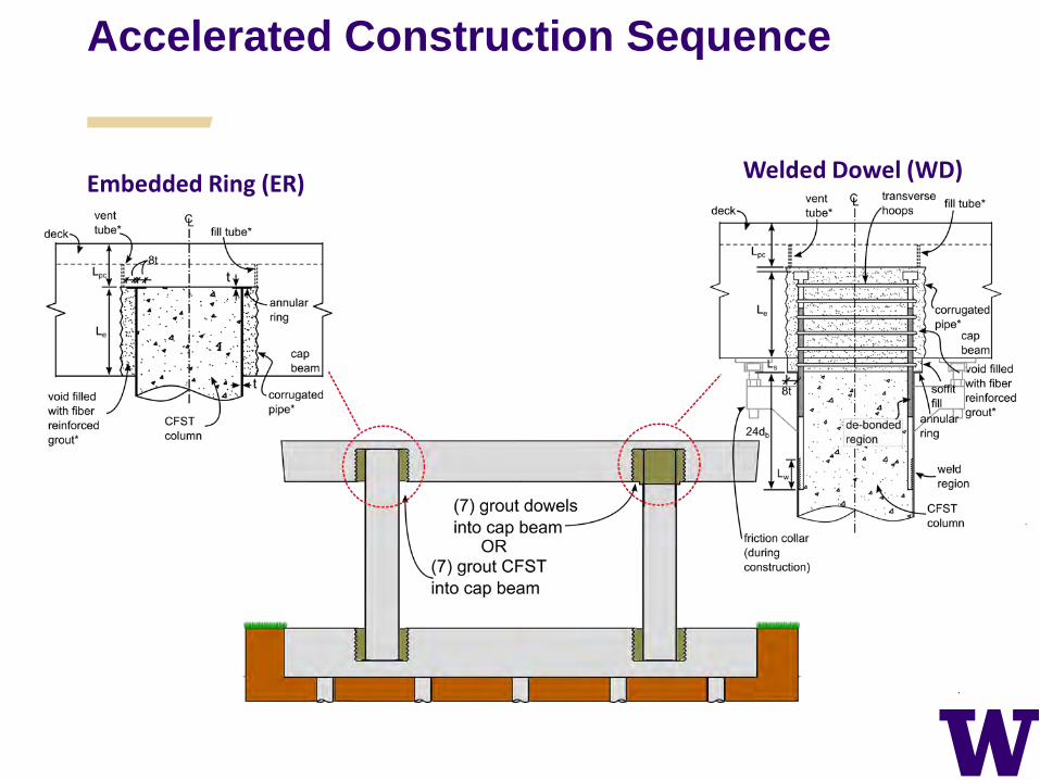
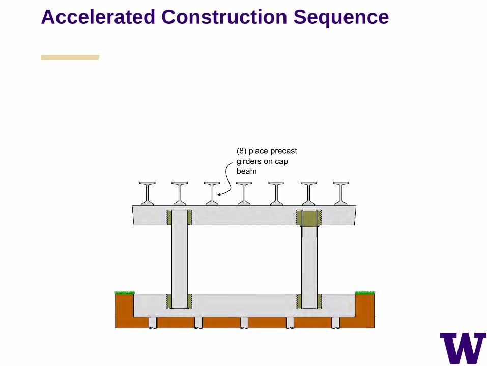
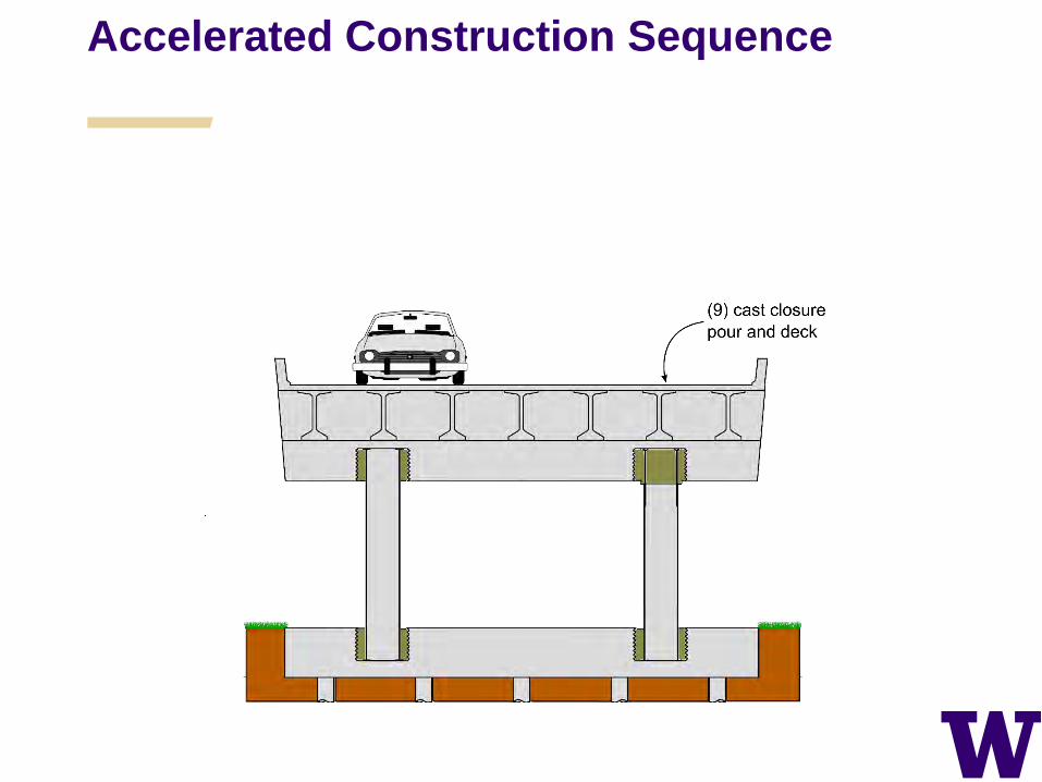
Accelerated Construction Sequence

Accelerated Construction Sequence
Accelerated Construction Sequence
Accelerated Construction Sequence
Accelerated Construction Sequence
Accelerated Construction Sequence
Accelerated Construction Sequence
Welded Dowel (WD) Embedded Ring (ER)
Accelerated Construction Sequence
Accelerated Construction Sequence
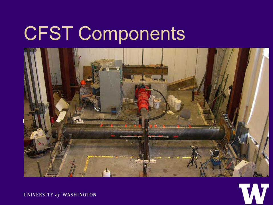
CFST Components
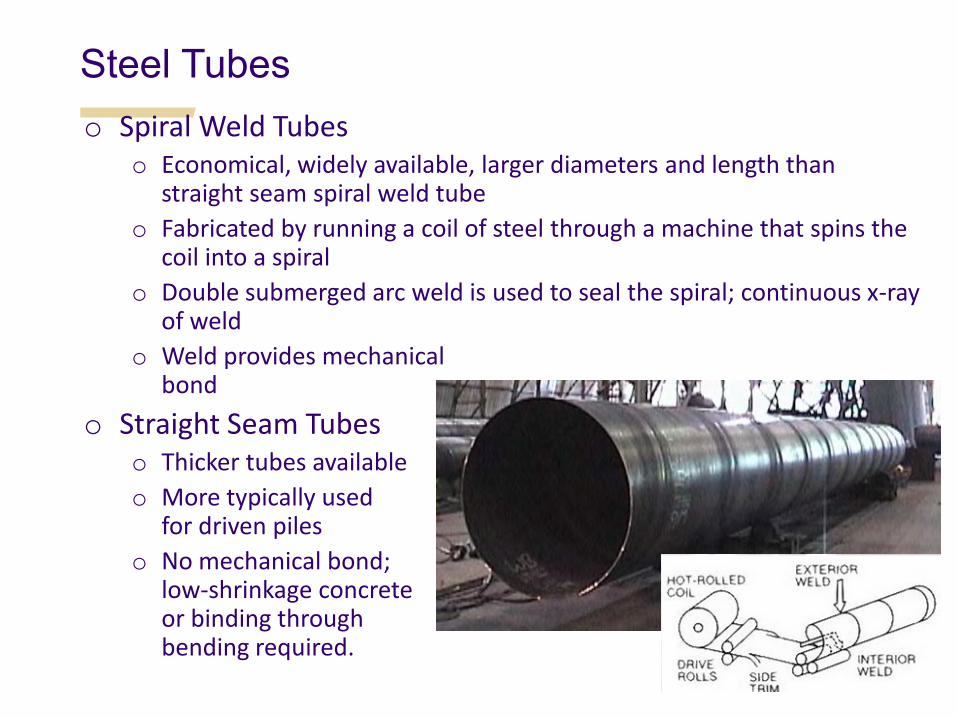
Steel Tubes o Spiral Weld Tubes
o Economical, widely available, larger diameters and length than straight seam spiral weld tube
o Fabricated by running a coil of steel through a machine that spins the coil into a spiral
o Double submerged arc weld is used to seal the spiral; continuous x-ray of weld
o Weld provides mechanical bond
o Straight Seam Tubes o Thicker tubes available o More typically used
for driven piles o No mechanical bond;
low-shrinkage concrete or binding through bending required.
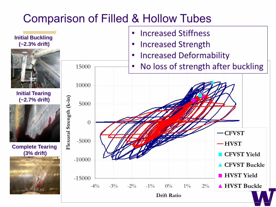
Comparison of Filled & Hollow Tubes
-15000
-10000
-5000
0
5000
10000
15000
-4% -3% -2% -1% 0% 1% 2% 3% 4%
Drift Ratio
Flex
ural
Str
engt
h (k
-in)
CFVST
HVST
CFVST Yield
CFVST Buckle
HVST Yield
HVST Buckle
• Increased Stiffness • Increased Strength • Increased Deformability • No loss of strength after buckling
Initial Buckling (~2.3% drift)
Initial Tearing (~2.7% drift)
Complete Tearing (3% drift)

B6KJM31TTBYW
Simple, filled-tube push-through tests and 3-point bending tests
t = ¼” d = 19 ½”
strain gage location typ.
rigid base support
air gap to allow slip
concrete fill length = 60”
applied load
welded wire gage location typ.
Applied Load 2.4m lb. UTM
Instrumented 20 in. Dia. Tube
Tube Concrete
Conventional
Low Shrinkage
Conventional
Low Shrinkage
Straight Seam
Spiral Weld
4-Test Matrix
Composite Action in CFST
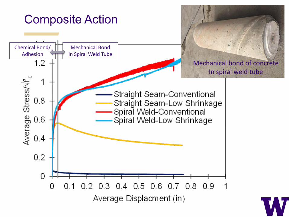
Composite Action
Chemical Bond/ Adhesion
Mechanical Bond In Spiral Weld Tube
Mechanical bond of concrete In spiral weld tube
Shear Strength of CFST
> Current design expressions include steel tube only or treat CFST as an RC section with Vn = Vs + Vc
> Neither approach is correct > Both underestimate the shear strength by a factor of at
least two > Testing investigated: (a) aspect ratio, (b) D/t, (c)
concrete strength, (d) internal reinforcement ratio, (e) tail (anchorage) length, (f) axial load ratio
> Results show that CFST sections are very strong in shear.
21 tests on CFST specimens conducted. New expression proposed.

o Steel rupture
o Significant permanent shear deformation in steel
o Large localized deformation at bearing locations
o No visible flexural deformation in pure moment region
Example of Shear Failure of CFST
> a/D = 0.25 > D/t = 80 > f’c = 6 ksi
Post-Test Internal Concrete Damage

Connection Tests
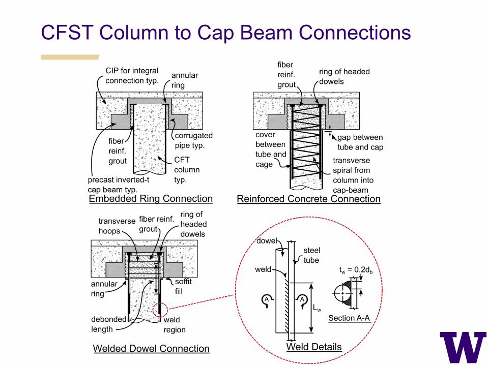
CFST Column to Cap Beam Connections

Embedded Ring (ER) Connection
buckling visible
①
② ③
④
initiation of tearing
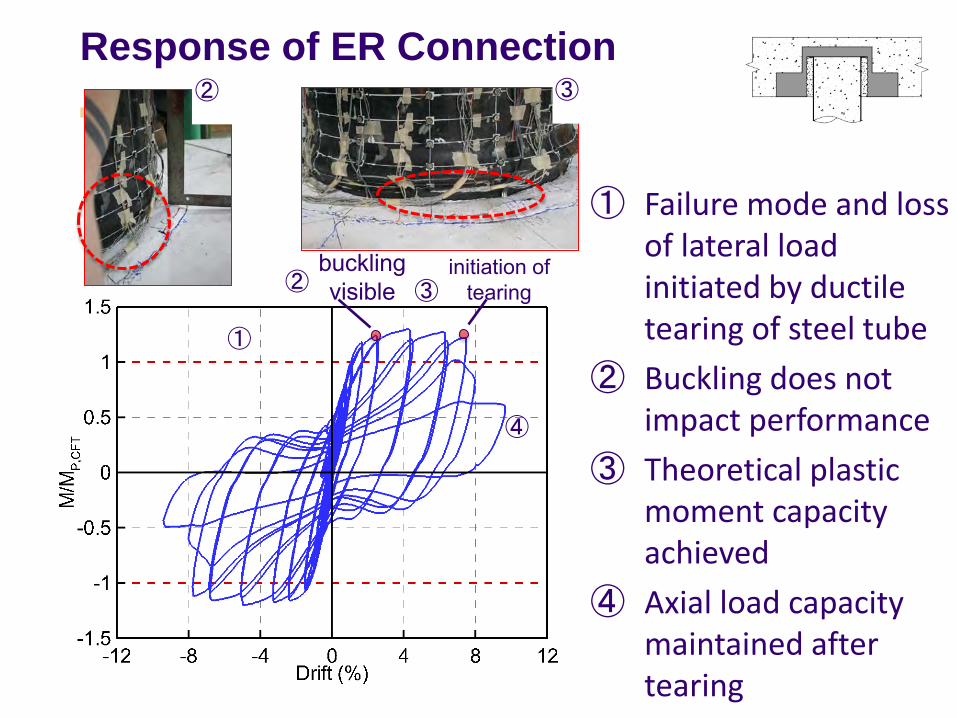
Response of ER Connection
① Failure mode and loss of lateral load initiated by ductile tearing of steel tube
② Buckling does not impact performance
③ Theoretical plastic moment capacity achieved
④ Axial load capacity maintained after tearing
②
③
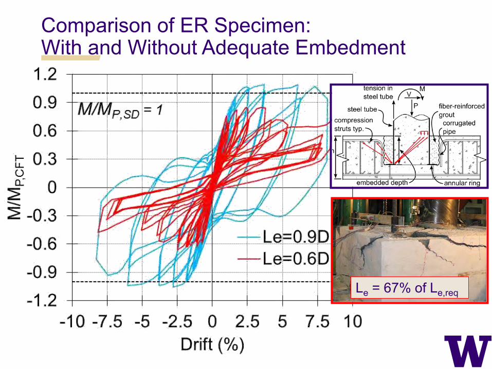
Comparison of ER Specimen: With and Without Adequate Embedment
Le = 67% of Le,req

Debonded, Welded Dowel Connection
D (in) t (in) D/t P/Po Reinforcing Steel Fy (ksi) f’c (ksi) ρL(%) (fy/f’c)ρL
25.75 0.25 103 0.10 A706 Grade 60 68 7.7 3 0.3

Performance of WD Connection
① Achieved symmetric drifts of up to 9% with no degradation
② Theoretical plastic moment capacity of CFT achieved due to similar mechanical reinforcing ratio
7.5% Drift
Rocking

Reinforced Concrete (RC) Connection

Performance of RC Connection
north bar fracture
northwest and northeast bar fracture
south bar fracture
southwest and southeast bar fracture
o Failure mode fracture of reinforcing bars (~8% drift)
o Strength limited by reinforcing ratio and moment arm
12% Drift
Final State Grout damage

Key Considerations for ER Connection
① Annular Ring Dimensions ② Anchorage Depth of CFST ③ Punching Shear above Annular Ring ④ Cap beam reinforcing
1
3
2
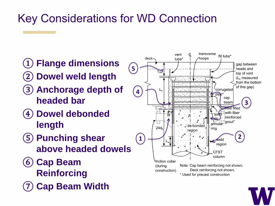
Key Considerations for WD Connection
① Flange dimensions ② Dowel weld length ③ Anchorage depth of
headed bar ④ Dowel debonded
length ⑤ Punching shear
above headed dowels ⑥ Cap Beam
Reinforcing ⑦ Cap Beam Width
1
4
2
5
3
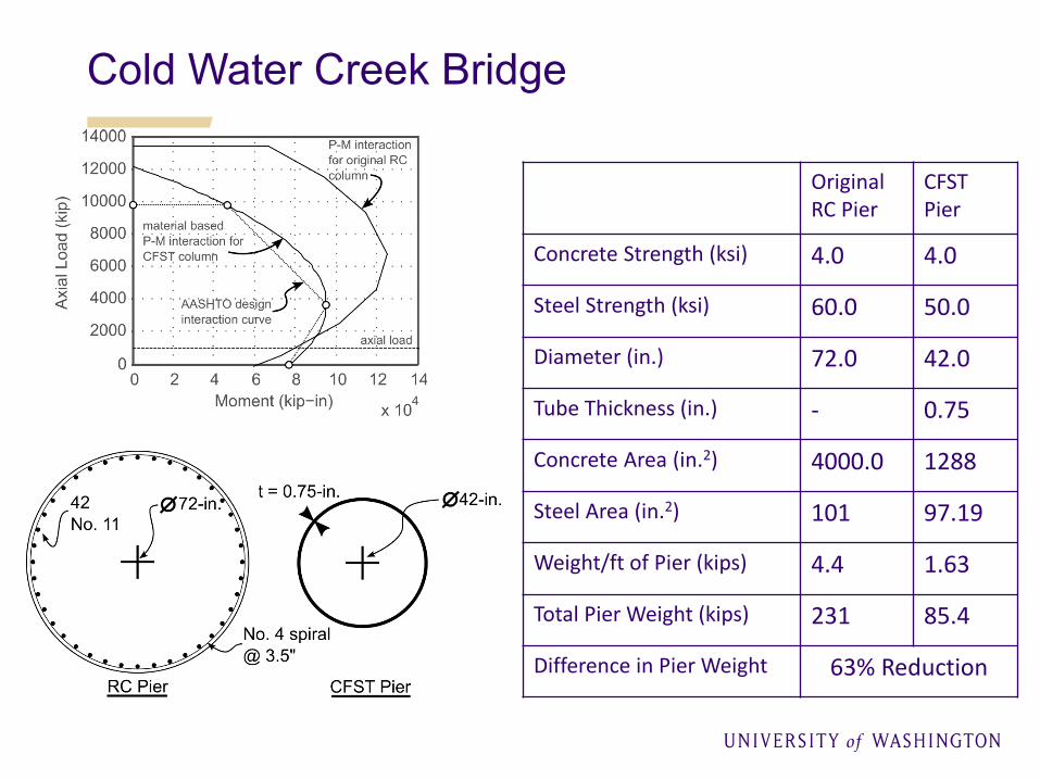
Original RC Pier
CFST Pier
Concrete Strength (ksi) 4.0 4.0
Steel Strength (ksi) 60.0 50.0
Diameter (in.) 72.0 42.0
Tube Thickness (in.) - 0.75
Concrete Area (in.2) 4000.0 1288
Steel Area (in.2) 101 97.19
Weight/ft of Pier (kips) 4.4 1.63
Total Pier Weight (kips) 231 85.4
Difference in Pier Weight 63% Reduction
Cold Water Creek Bridge

Comparison in Terms of Accelerated Bridge Construction
> ER connection offers several advantages in terms of ABC – No dowels or transverse reinforcing required – Precast cap can be placed directly onto column
> WD connection has several drawbacks – Welding and inspecting welds within the steel tube is
difficult – Temporary shoring required when using precast cap beam – Transverse reinforcing required around longitudinal dowels
> RC connection not conducive to ABC – Requires flexible reinforcing cage supported within the
steel tube – Temporary shoring required when using precast cap
From Research to Implementation • Design and Detailing Recommendations
for Bridge Design Manual • Material Specifications for Concrete and
Steel Casing • Bond Slip Requirements • Design Expressions for Flexure, Axial, and
Shear Resistance • CFT and RCFT Connections to Cap and
Foundation (Column, pile and Shaft)
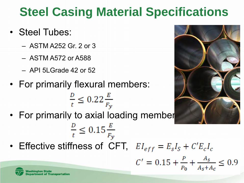
Steel Casing Material Specifications • Steel Tubes:
– ASTM A252 Gr. 2 or 3
– ASTM A572 or A588
– API 5LGrade 42 or 52
• For primarily flexural members:
• For primarily to axial loading members: • Effective stiffness of CFT,

Welding and Inspection - AASHTO/AWS D1.1 Structural
longitudinal or spiral seam submerged-arc welded tube
Visual testing (VT) throughout Ultrasonic testing (UT) in high
stress areas Complete Joint Penetration
welds w/ backing
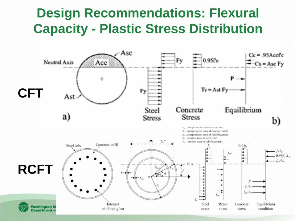
Design Recommendations: Flexural Capacity - Plastic Stress Distribution
CFT
RCFT
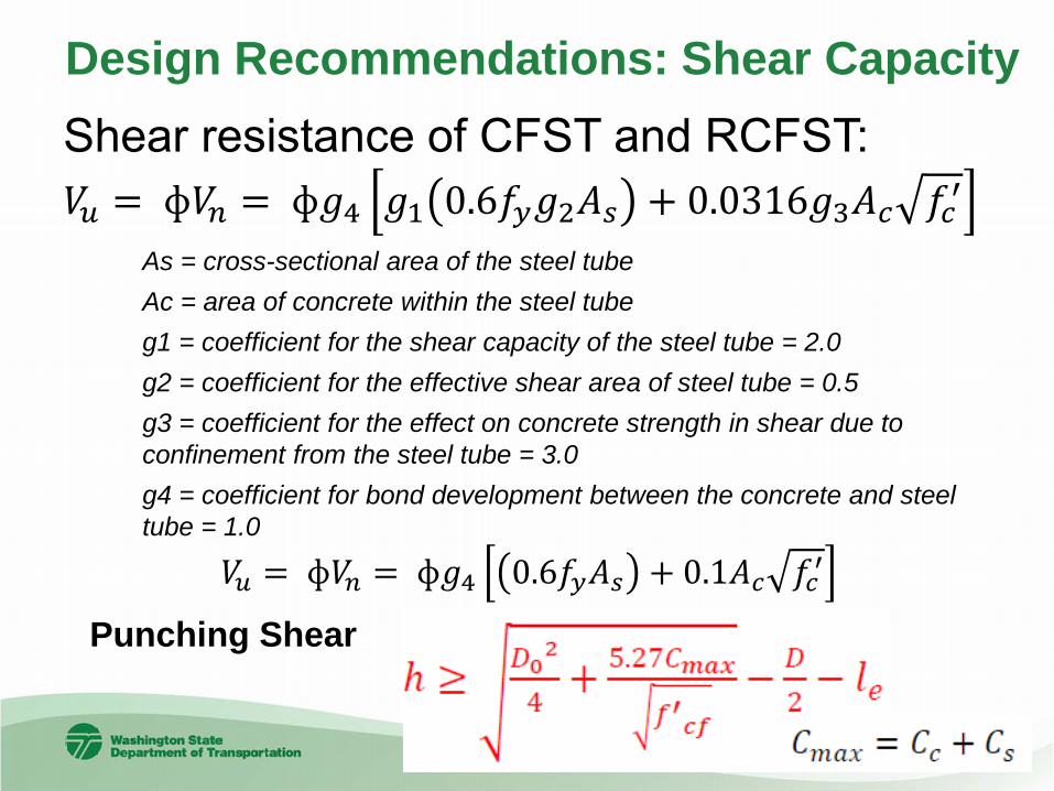
Shear resistance of CFST and RCFST: 𝑉𝑉𝑢𝑢 = ф𝑉𝑉𝑛𝑛 = ф𝑔𝑔4 𝑔𝑔1 0.6𝑓𝑓𝑦𝑦𝑔𝑔2𝐴𝐴𝑠𝑠 + 0.0316𝑔𝑔3𝐴𝐴𝑐𝑐 𝑓𝑓𝑐𝑐′
Design Recommendations: Shear Capacity
As = cross-sectional area of the steel tube Ac = area of concrete within the steel tube g1 = coefficient for the shear capacity of the steel tube = 2.0 g2 = coefficient for the effective shear area of steel tube = 0.5 g3 = coefficient for the effect on concrete strength in shear due to confinement from the steel tube = 3.0 g4 = coefficient for bond development between the concrete and steel tube = 1.0
Punching Shear
𝑉𝑉𝑢𝑢 = ф𝑉𝑉𝑛𝑛 = ф𝑔𝑔4 0.6𝑓𝑓𝑦𝑦𝐴𝐴𝑠𝑠 + 0.1𝐴𝐴𝑐𝑐 𝑓𝑓𝑐𝑐′
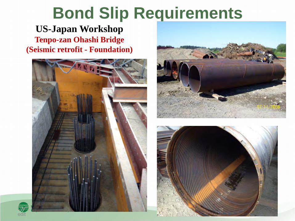
Bond Slip Requirements
Date, time and initials of last edit
47
US-Japan Workshop Tenpo-zan Ohashi Bridge
(Seismic retrofit - Foundation)
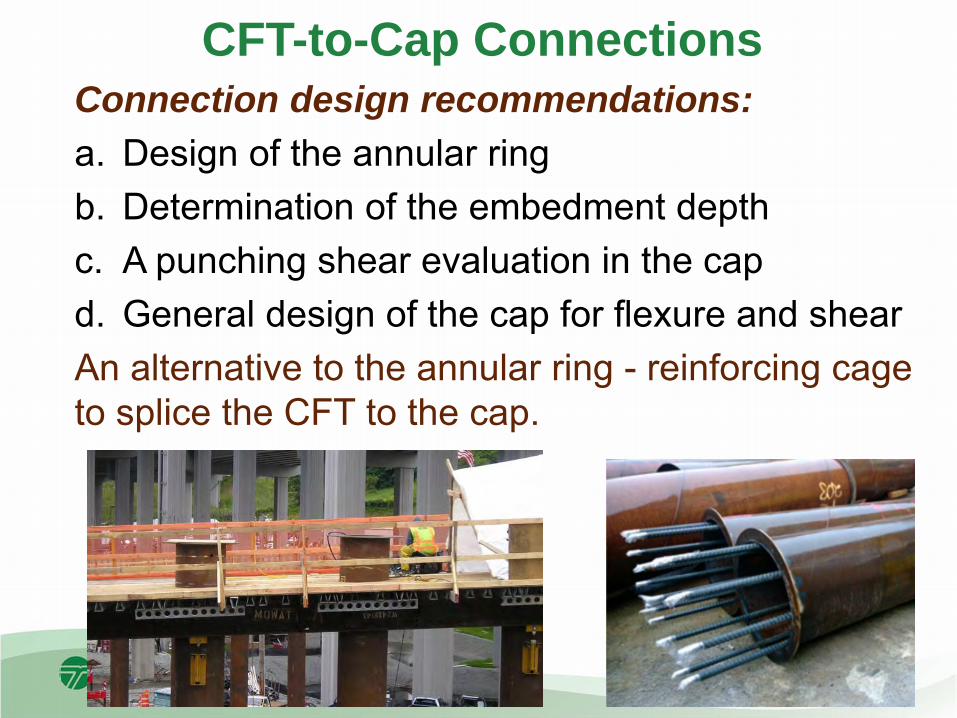
CFT-to-Cap Connections Connection design recommendations: a. Design of the annular ring b. Determination of the embedment depth c. A punching shear evaluation in the cap d. General design of the cap for flexure and shear An alternative to the annular ring - reinforcing cage to splice the CFT to the cap.

CFT-to-Cap Connections - Annular Ring Embedded flange connection: • Size the flange to develop the
casing, 16t • Embed the flange to prevent
pullout of the tension side • Provide cover to prevent
breakout on compression side • Cone Pullout Mechanism for
Cap Connections • Fillet welds to develop the full
tensile capacity of the tube
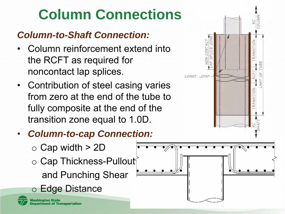
Column Connections: Column-to-Shaft Connection: • Column reinforcement extend into
the RCFT as required for noncontact lap splices.
• Contribution of steel casing varies from zero at the end of the tube to fully composite at the end of the transition zone equal to 1.0D.
• Column-to-cap Connection: o Cap width > 2D o Cap Thickness-Pullout and Punching Shear o Edge Distance
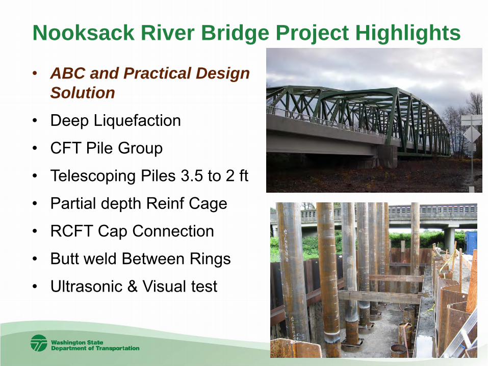
Nooksack River Bridge Project Highlights
• ABC and Practical Design Solution
• Deep Liquefaction
• CFT Pile Group
• Telescoping Piles 3.5 to 2 ft
• Partial depth Reinf Cage
• RCFT Cap Connection
• Butt weld Between Rings
• Ultrasonic & Visual test

Date, time and initials of last edit 52
Alaskan Way Viaduct Highlights
• ABC and Practical Design Solution
• Deep Liquefaction and Lateral Spread
• CFT Pile Group
• RCFT and CFT
• Partial depth Reinf. Cage
• Telescoping Piles 5 to 3 ft
• RCFT Cap Connection

Ebey Slough Bridge Highlights
• ABC and Practical
Design Solution
• RCFT and CFT - 5’ and 6’
• Partial depth Reinf Cage
• Liquefaction/Lateral
Spread • RCFT Cap Connection
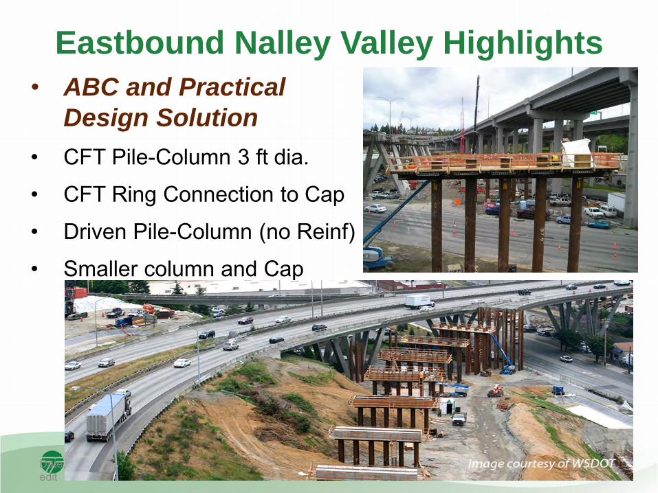
Eastbound Nalley Valley Highlights
Date, time and initials of last edit 54
• ABC and Practical Design Solution
• CFT Pile-Column 3 ft dia.
• CFT Ring Connection to Cap
• Driven Pile-Column (no Reinf)
• Smaller column and Cap
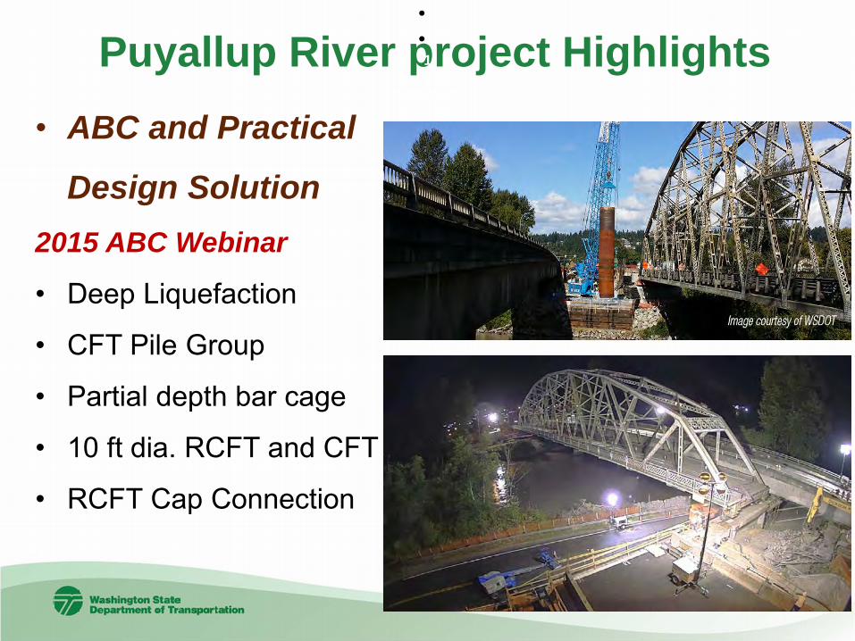
Puyallup River project Highlights • ABC and Practical
Design Solution 2015 ABC Webinar
• Deep Liquefaction
• CFT Pile Group
• Partial depth bar cage
• 10 ft dia. RCFT and CFT
• RCFT Cap Connection
• • 1 2
PrevNext
Future: CFT – RCFT Could be used in:
Accelerated Bridge Construction Projects Temporary Piers and Columns Bridge with Deep Foundation Sites where permanent casing is required
for caving soils Sites with Liquefiable soils where plastic
hinging is required Other applications as appropriate

Resources: • WSDOT BDM and UW Research Reports BDM - http://www.wsdot.wa.gov/publications/manuals/fulltext/M23-50/Chapter7.pdf UW Report-http://www.wsdot.wa.gov/Research/Reports/700/776.1.htm UW Report-http://www.wsdot.wa.gov/research/reports/fullreports/776.1.pdf
University of Washington Contacts: Research: Dawn Lehman: [email protected] Research: Charles Roeder: [email protected] WSDOT Contacts: Foundation: Anthony Mizumori [email protected] Steel: Geoff Swett, [email protected] ABC: Jed Bingle, [email protected] [email protected] Thank You


![a c:] 5 ooÐ L B 10.5 1 - Microsoft Word Abc Abc Abc Abc Abc Abc Abc Abc Abc Abc Abc Abc 1 - Microsoft Word Abc Abc Abc 505 7ï—L Mic SmartArt 1 - Microsoft Word Aa MS B 10.5 (Ctrl+L)](https://static.fdocuments.in/doc/165x107/5b180d777f8b9a19258b6a1e/a-c-5-ood-l-b-105-1-microsoft-word-abc-abc-abc-abc-abc-abc-abc-abc-abc-abc.jpg)