Concrete Cracks in Swimming Pool Basins - Diva1105755/FULLTEXT01.pdf · Concrete Cracks in Swimming...
59
KTH Byggvetenskap Samhällsbyggnad Kungliga Tekniska Högskolan Concrete Cracks in Swimming Pool Basins Betongssprickor I Simbassänger Examensarbete i byggnadsteknik No 456 Byggvetenskap 2017 06 02 Ragheed Hussain and Salman Shawkat Handledare Tord Af Klintberg, KTH Byggvetenskap Folke Björk, KTH Byggvetenskap
Transcript of Concrete Cracks in Swimming Pool Basins - Diva1105755/FULLTEXT01.pdf · Concrete Cracks in Swimming...
KTH Byggvetenskap
Samhällsbyggnad
Kungliga Tekniska Högskolan
Concrete Cracks in Swimming Pool Basins
Betongssprickor I Simbassänger
Examensarbete i byggnadsteknik
No 456
Byggvetenskap
2017 06 02
Ragheed Hussain and Salman Shawkat
Handledare
Tord Af Klintberg, KTH Byggvetenskap
Folke Björk, KTH Byggvetenskap
Abstract
Majority of the swimming facilities in Sweden are facing some form of renovation or
total substitution.
The report analyses cracks in two different public bath facilities namely
Eriksdalsbadet and Enskedehallen. The text also discusses different solution
strategies for cracks in concrete.
The aim with this thesis is to discuss how facility managers can extend the service life
of these facilities by taking measures against the crack damages. Since renovation
can be expensive, it is important to study cracks early on when they appear. This
thesis also emphasizes on how important it is to add resources for preventing cracks,
already during casting. Resources should also be added for maintaining the basins,
managing repair methods for all types of cracking problems.
This thesis is more of a generalized study for cracks in concrete, however it concludes
with taking a more specific approach by discussing the problems in swimming
basins. Causes of cracks, different types of cracks and evolution of cracks are studied
and discussed with emphasis on the structural damages that can occur.
With pictures taken and analyzed from the two facilities and a visitation with a
experienced concrete investigator from CBI, this thesis concludes with a decision to
immediately take repair actions against cracks that are shown in the report. The
report discusses two perspectives, one where the authors of the thesis discusses
solutions derived from information given in the report, and the other perspective is
derived from guided inspection with consultant from CBI.
Keywords
Concrete, Cracks, Corrosion, Swimming facilities, Repair methods
i

Sammanfattning
Majoriteten av simhallarna i Sverige står inför någon form av renovering, eller total
substitution.
Den här rapporten analyserar sprickor i två olika offentliga badanläggningar,
nämligen Eriksdalsbadet och Enskedehallen. Texten diskuterar också olika
lösningsstrategier för sprickor i betong.
Syftet med denna avhandling är att diskutera hur anläggningsansvariga kan förlänga
livslängden för dessa anläggningar genom att vidta åtgärder mot sprickskador.
Eftersom renovering kan vara dyrt är det viktigt att studera sprickor, strax efter de
dyker upp. Avhandlingen betonar också hur viktigt det är att lägga resurser för att
förhindra sprickor, redan vid första steget. Resurser borde också läggas för att
upprätthålla bassängerna, hantera reparationsmetoder för alla typer av
sprickproblem-
Denna avhandling är mer av en generaliserad studie för sprickor i betong, men det
slutar med att ta en mer specifik rutt genom att diskutera mer om problemen i
simhallsbassänger. Orsaker till sprickor, olika typer av sprickor och sprickutveckling
studeras och diskuteras med vikt på dom strukturala skador som kan uppstå.
Med bilder tagna och analyserade från de två anläggningarna, och en visitation med
en erfaren betong utredare from CBI, så resulteras avhandlingen med ett beslut att
omedelbart vidta reparationsåtgärder mot sprickor som visas i rapporten. Rapporten
diskuterar två perspektiv, en där uppsatsens författare diskuterar lösningar som
härrör från information som ges i rapporten, och det andra perspektivet härrör från
guidad inspektion med konsult från CBI.
Nyckelord
Betong, Sprickor, Korrosion, Simhallar, Reparationsmetoder
ii
Preface
As completion of our studies on the master’s program Civil and Architectural
Engineering in KTH (Royal Institute of Technology), this thesis has been written.
This report has been written for the “Neris project” with a collaboration between
KTH and Stockholm Stad. We would like to take this opportunity to thank our
supervisors Folke Björk and Tord Af Klintberg, who have helped us greatly to
complete the report. We would also like to thank Elvy Löfvenberg from Stockholm
Stad for helping us with visitations to the facilities. Finally, we would like to give
thanks to Dennis Lundgren who gave us an experienced perspective to add to the
thesis.
Stockholm 30 May 2017
Ragheed Hussain and Salman Shawkat
iii
Table of Contents Abstract.................................................................................................................................. i
Sammanfattning ..................................................................................................................... ii
Preface ................................................................................................................................. iii
1. Introduction ....................................................................................................................... 1
2 Aim .................................................................................................................................... 2
3 Method ............................................................................................................................... 2
3.1 Delimitations ................................................................................................................ 2
3.2 Expectations ................................................................................................................ 2
4 Result................................................................................................................................. 3
4.1 Concrete ...................................................................................................................... 3
4.11 Water cement ratio ................................................................................................. 4
4.12 General swimming basin construction .................................................................... 5
4.2 Cracks ......................................................................................................................... 6
4.21 Introduction ............................................................................................................ 6
4.22 Classification of cracks ........................................................................................... 6
4.23 Causes of cracks.................................................................................................... 8
4.3 Solutions.................................................................................................................... 26
4.31 Measurement of cracks ........................................................................................ 26
4.32 Methods for repairing cracks and corrosion .......................................................... 31
6. Discussion ...................................................................................................................... 37
7. Conclusion ...................................................................................................................... 39
8. Future Studies ................................................................................................................. 39
7. References ..................................................................................................................... 40
8. Appendix ......................................................................................................................... 42
1
1. Introduction
In the field of structural engineering, swimming pools are considered to be special
constructions. For designing and constructing swimming pools, a high level of
expertise is required. In addition to this, the requirements are high for the quality of
the material used in the construction. Since swimming pools are constructed for an
environment where high level of moisture is present, it becomes even more
important to act according to the requirements. Because the purpose of the
construction is to function as a water container, a large amount of additional
material is required for example to reduce the permeability in the concrete.
Knowledge for extensive concrete technology, detailed planning of joint formation
and high quality safety measures are needed, before the construction of a waterproof
concrete shell can begin. Mistakes in design of the execution of the construction can
lead to devastating repair works. The knowledge for how to distribute the chloride in
the water (in the pool) and the variation in temperatures in the swimming facilities
will greatly influence the service life of the construction.
Eriksdalsbadet was built 1999 and this facility is Sweden’s national swimming
facility. It has two main swimming basins which are built for an attendance of 2900
people together. Apart from these basins there are smaller basins for teaching and
other purposes.
Enskedehallen is a smaller swimming- and sports facility located south of Stockholm.
This facility was built in 1967. So, it is about 30 years older than Eriksdalsbadet. The
concrete of these two facilities were examined for this thesis. Mainly, the cracks were
looked upon and pictures were taken. Later in the thesis these pictures will be
categorized in a form of how severe the cracks are.
This report is dedicated to the cracks in the concrete of the two swimming pools
mentioned above. How these cracks appear and how cracking problems can be
solved. Cracking in concrete is a phenomenon which is recognized world-wide. Some
cracks are acceptable and will not harm the entire construction. But in some
constructions, there are cracks that can lead to serious defects. In those
constructions, the cracks can affect the strength, function, appearance and general
health issues. The current reaction to cracking is often dissociated from the
significance of the crack in the situation in which it occurs. There is some sort of
attention that is paid to the problems that occur because of cracks, but this attention
needs to be much larger. The reaction can vary a lot between concerns about the
presence of a single hair crack to the view that cracks are a part of the nature in
concrete. Those who share this view believe that even wider cracks can be ignored
since they are a part of the concrete nature. This report discusses the how cracks can
damage a structure, and how to take measures against these cracks to repair them.
There are many factors why cracks can occur and one of the biggest factors is from
corrosion, and some of the other factors are discussed in this report.

2
The corrosion of reinforcing steel is often recognized as the major cause of damaging
concrete structures around the world. It is important to mention that corrosion can
occur without any direct limitation of the concrete itself. Whether it is normal
Portland cement concrete quality (OPCC) or high performance concrete quality
(HPC). In fact, OPCC provides an ideal environment for protecting the structure
from corrosion, but even then, corrosion can occur, depending on the function of the
structure.
2 Aim
The aim of this report is to find cracks in swimming facilities, study them and discuss
methods for repairing these cracks, to extend the service life of these facilities.
Constructing swimming pools is expensive, hence it is important to often
strategically renovate and manage repairs of the constructions.
3 Method
This report was based on three method choices:
1) Literature study: Most of this thesis is based on studies made by the authors,
where several types of references was used: Books, websites, reports and
journals.
2) Study visit: Initially, before starting this report a study visit was made to the
two different swimming facilities in question. Pictures were taken and
analyzed for this thesis.
3) Visit with consultant from CBI: This visit was made in the later stages in the
thesis to conclude all the literature study that has been made. During this visit,
a visual investigation and simple knocking on concrete test was performed by
an experienced concrete consultant from CBI concrete institute. The results
from the investigation can be found in the appendix section of this report.
3.1 Delimitations
This report assumes that the swimming basins are made of concrete.
The repair methods, solutions and strategies are intended for concrete structures, in
particular concrete structures with swimming purposes.
3.2 Expectations
Our expectation for this report is to give the reader an insight and understanding of
what problems the concrete in a swimming pool facility can meet. We also expect to
learn more about the material concrete and reinforcement steel. We also want to
understand more about how damages can be prevented.
3
4 Result
4.1 Concrete
Concrete is a long-lasting and durable material which is cost-effective. When
something is built with concrete, it is built to last a long time. The service life of
concrete structures is about 100 years. Obviously, this service life is based on repairs
and maintenance on the structure. However, usually it all adds up to a solid
investment. Concrete is also economical, when it comes to energy-efficient
structures, where it provides one of the most efficient ways of constructing energy-
efficient buildings. Concrete is also considered to be safe. It does not burn, feed rot or
mildew. It provides excellent indoor air quality and does not release any organic
compounds. Another reason concrete is the leading material for construction is
because it occurs naturally; hence it has been around for a while. For this reason,
concrete has been refined over time and is today well understood unlike new
materials or systems which could compromise health. Concrete is also
environmentally friendly. In the life cycle of concrete, recycling exists from start to
finish. Many wastes that usually would end up in landfills for other materials are
used in the cement or can be added to other concrete mixes. Used concrete is
recycled and serves as aggregate for other structures. (Concretesask, 2017)
Concrete is a mix of cement, water and aggregate. In addition, sometimes there are
admixtures added. The cement combined with the water functions as a glue to hold
the different materials (aggregate) together, like stone, sand and gravel. Suitable
materials must be included or used for making the concrete to ensure that the
concrete is of high quality. The strength and the durability are also dependent on
what kind of concrete is used. The use of the concrete is also important for quality
requirements, such as handling the concrete, compaction, finishing the casting...etc.
Following is a brief description of what is important to know about the different
components in concrete;
1) Cement
Cement plays a great role when it comes to the properties of the concrete. There are
many of important characteristics in cement that should be considered. What type of
cement it is, what the main compound is and minor compounds such as alkalis and
phosphates.
The compressive strength and fineness is also important to look at. The cement
should be considered from the beginning for many reasons but one of the most
important reason is because during maintenance and defect treatment, the same
cement type should be used.
2) The aggregate
The aggregate (gravel and sand) represents normally 75 % of the concrete. As
mentioned above, the cement and the water is there to function as glue to hold the
4
aggregate mixture together. It is important to know what kind of aggregate is used,
what the maximum aggregate size is and the sulfate content in the aggregate. The
percentage of organic materials is also important to study.
3) Water
The water can be used to produce fresh concrete and to repair hardened concrete.
The water must be clean, meaning it cannot contain any acidic materials, salts or
other chemicals. Generally, water in Sweden is clean and does not need to go through
complex cleaning processes.
4) Admixtures
As mentioned above, sometimes admixtures are used in the concrete, to get closer to
the desired characteristics of the concrete. Some of the admixtures are accelerators,
retarders, air entrained admixtures and water expelling admixtures. According to
Europe specifications, one can study the admixture quality. Generally, what must be
known is what type of admixture, side effects, suitability for the structure and future
treatment.
5) Concrete handling and compaction
How the concrete is processed and how it is handled is important for the quality of
the concrete. To insure high quality concrete and avoid defects there must be some
limitations. For example, homogenous mixture, good compaction to assure highest
possible density and the casting process of concrete must take place in limited time.
The concrete also must be workable enough to fill the form.
4.11 Water cement ratio
The water cement ratio is of great importance when it comes to the consistency of the
concrete. The water cement ratio can be defined as volume of water over the volume
of cement used in the concrete mix. When additive materials are used the water
cement ratio is volume of water over the volume of cement and additive materials. As
mentioned above, water plays an important role in the concrete and affects the
workability and strength.
Figure 1, Diagram of water cement ratio and compressive strength (Dailycivil, 2017)
5
Figure 1 illustrates how the compressive strength changes depending on what the
water cement ratio is. The diagram shows that the less water there is in the concrete,
the higher the compressive strength is. But water is inevitable and must be present in
the concrete mix. Water is also important for the concrete to be workable as
mentioned above. If less water is used, the concrete will dry faster and that will make
it more difficult for the concrete to be placed in the shape that is desired. If more
water is used then it decreases the durability, strength and density of the concrete,
creating construction problems. Hence, the water cement ratio needs to be examined
and determined according to the function of the structure. (Dailycivil, 2017)
When it comes to the water cement ratio, slump test is the simplest test for finding
the workability (implying the water cement ratio) of the concrete. But there are
various factors that can affect the concrete slump value. This test is well known and
often used because it involves low cost and provides immediate results. Slump test is
proceeded as stated in ASTM C143 in the United States and EN 12350-2 in Europe.
This method is reliable when it comes to determining how fresh concrete will behave
during casting. (Shetty, December)
4.12 General swimming basin construction
The construction for the swimming basin is performed almost with the same
principles, as it was performed in the 50-60 century. The basin construction includes
the basin and its body, with connecting basin deck around the basin. Reinforced cast
concrete has always been the recommended solution for almost every pool
constructions in Sweden. Concrete is a flexible material that can be molded into
almost any geometric shape. Concrete is also used in swimming facilities since it is
waterproof and requires little maintenance. It will be mentioned below but since
swimming facilities are obviously used for environments where the moisture level is
extremely high, it is extremely important to waterproof the concrete even more.
Sealing layers’ needs be used so that the water cannot penetrate through the
concrete. Usually the sealing layer is chosen after the additional material in the
swimming water is known, since the additional material affect the layer. If the
concrete that is used is waterproof then the entire basin is waterproof in itself,
provided that the corners and the joints are performed correctly. Ardex is one of
many companies in Sweden that works with sealing layers for concrete constructions
that are not so waterproof. If the concrete is of inferior quality then the constructions
needs to be protected with, for instance Epoxy-membrane.
Normally if the construction is done performed according to Europe standard, with
regards to Sweden’s, or in this case Stockholm’s environment, then the construction
usually meets its service life with a few repairs done.
How were the basin constructed? What concrete?

6
4.2 Cracks
4.21 Introduction
Cracking in concrete is a phenomenon which is recognized world-wide. Because
cracks cause damages to buildings and concrete structures, it is extremely important
to keep studying it. Defects commonly appear in both reinforced and plain concrete
structures, especially in countries where most of the constructions are built with
concrete. In some situations, the cracks do not harm the constructions and are totally
acceptable. In other constructions, cracks are serious defects and it adversely affect
function, quality, strength, or appearance. In these cases, causes of cracks and the
methods to repair them are to be studied to maintain building safety and ensure long
service life and durability. Cracks may be different according to their types, shapes,
and their causes. Hence, it is important to know what type of crack it is to find a
suitable repair method and in addition suggest suitable materials to repair with.
4.22 Classification of cracks
Cracked concrete is usually a symptom rather than a fault. Cracks do not result in
structural failure in many cases, but they can result in definite loss of performance of
the structure by causing accelerated weakening and potentially rendering the
structure to become unserviceable.
Generally, there are two crack types and there are many reasons behind them;
1. Structural cracks
These are the cracks that take place in reinforcement structural members. Usually
these cracks take place in foundations, columns or beams. They are often dangerous
and need rapid treatment.
2. Non-structural cracks
These are the cracks that occur due to other reasons, that are not those of structural
cracks. Usually these cracks are initially not dangerous; hence they do not harm the
structure. However, when ignored they can transform into dangerous cracks and the
effect of this may accumulate to be damaging to the structure.
Cracks can be classified by their direction and dimensions. Like width, depth,
whether they are vertical or diagonal…etc. Regarding the direction at the surface of a
concrete wall or slab, there are usually two main kind of cracks; map cracks or
pattern cracks. Map cracks are uniformly distributed cracks and they run in all
directions. Map cracks indicate that there is restraint of surface layer by the concrete
or the backing. The other is pattern cracks. These cracks are parallel at definite
intervals. The indication of these cracks is that there is restraint perpendicular to
them. Usually, cracks that appear and continue to expand and move are considered
active cracks. Cracking is called dormant, when the cause is a factor that is not
expected to occur again. Under this category, plastic cracks and cracks that come
from temporary overloading exists. (A.M, 2005)

7
Generally, there are three width ranges of cracks that commonly referred to:
• Fine – usually less than 1 mm in width
• Medium - between 1 and 2 mm
• Wide over 2 mm (Murray, 1978)
Cracks up to 0.3 mm wide are usually aesthetically acceptable. However, they can be
damaging. Below is a list of when different widths for cracks are recognized for
severe exposures:
• 0.1 mm – In industrial or marine environment where water tightness is
essential
• 0.2 mm – For general external exposures, or internal exposure of the
members in a humid or rather aggressive atmosphere
• 0.3 mm – For internal and protected members (Murray, 1978)
Cracks can also be classified into two broad categories. These cracks occur before the
hardening process of the concrete, and after hardening process, when the concrete
has hardened.
Below is a general crack classification:
• Moving cracks – Cracks which “moves”, meaning their lengths, widths or
depths expands. These are the most severe and damaging cracks and requires
experience and studies for reparation
• The constant cracks – The factors that caused these cracks have been repaired
or removed. So, these cracks stay constant in their dimensions. They are less
dangerous since they stopped expanding and increasing, hence they are easier
to repair
• Fresh concrete cracks (before hardened concrete) – These cracks usually take
place during the casting process of the concrete. The “hair line cracks”, which
these cracks are called, appears on the surface of the concrete soon after the
casting process
• Hardened concrete cracks – These cracks take place once the concrete has
hardened. There are many reasons why these cracks appear but some of them
are; chemical attacks, shrinkage from drying, sulfate attack and settlement
effects (A.M, 2005)

8
4.23 Causes of cracks
There are many factors that cause cracks to occur. There are factors that can be
removed or repaired, so that they do not occur again and affect the existing cracks or
create new cracks. There are also factors that cannot be removed, for example usage
factors, like in swimming facilities water with chloride is in constant use which is a
factor for corrosion in the reinforcement. These factors need to be monitored and
minimized as much as possible. (Australia, 1978)
Below is a list of the main factors that cause cracks to appear:
• Poor quality of concrete – too high water content and use of excessively high
cement contents
• Poor structural design
• Hydration - the development of thermal stresses due to heat
• Tensile stresses that are developed due to restrained thermal expansion.
Tensile stresses appear also from contraction from temperature changes
• Cycles of wetting and drying leading to dimensional expansion and
contraction
• Bad workmanship, negligence and errors
• Corrosion of steel by chloride ions and carbonation of concrete
• Structural adjustments - movement in the foundation by settlement or
expansive soils
• Chemical attacks on the concrete both externally (sulfate attacks) and
internally (Alkali-aggregate)
• Improper use of the facility
• Heavy loading
4.231 The causes of non-structural cracks in concrete
4.2311 Before hardening
Cracks due to construction movement
Cracks take place when the soil goes down below the concrete within the period of
placing the concrete and gaining strength. The soil goes down due to the load,
because of two reasons. Either it’s moisture level changes which makes the soil
weaker or the soil is not compact enough. These cracks usually appear after some
hours or days post casting process. In conclusion, these are cracks that appear due to
soil movement.
Cracks that appear due to form movement usually appear when the concrete is newly
casted. Cracks may appear from the simple movements, and this usually happens
when the form design is unsuitable, the form wood saturates, the pins are loose or
too much concrete compaction. These cracks also appear within the early hours of
casting.

9
Cracks due to settlement shrinkage
Cracks near the steel bars occur when the upper part of the concrete partially sets
while aggregate particles still in sedimentation. Aggregate particles are the gravel,
crushed stone and sand in the concrete mixture. The sedimentation causes the water
to rise between aggregate particles, and then reduction in volume occurs and
concrete starts to fall in the form area. This leads to vertical cracks parallel to steel
bars. These cracks can damage and cause the concrete and steel bars to loosen bond.
Cracks like this occur usually in deep beams and within the early hours of casting.
Figure 2 below demonstrates this process. The gap is clearly shown under the steel
bar, hence, there is a loose bond between the concrete and the steel bar. Above the
steel bar, a surface crack is shown which occurs due to this process.
Figure 2, the sedimentation and shrinkage around the steel bars
We also have cracks around aggregate occurring due to the settlement shrinkage and
the process is similar to the process described above on steel bars.
Cracks due to setting shrinkage
Plastic shrinkage cracks occur when the evaporation from the surface of the concrete
occurs in a high velocity leading to bleeding meaning, the water rises to the concrete
surface. This occurs due to high wind velocity, high temperature and low relative
humidity, leading to shrinkage in the concrete surface more than the shrinkage
beneath the concrete. This leads also to tensile stresses in the concrete surface and
between 2 to 3 mm cracks starts to appear in the early hours.
Figure 3, plastic shrinkage cracks
There are also drying shrinkage cracks. These cracks appear due to evaporation of
the water that is between the concrete particles. The process usually lasts for a period
10
more than two years and causes the concrete to contract. The structural parts are
restrained by other structural parts and by the steel bars. Another reason for
movement restraint is that the surface is dryer than beneath the concrete. And as
mentioned above when the surface shrinkage is more than the shrinkage in the
concrete beneath the surface it leads to tensile stresses. The tensile stresses make
cracks occur that may penetrate the concrete within time and expands when the
concrete is exposed to drying shrinkage continuously. These cracks usually appear
after a couple of hours, and sometimes even after some weeks.
4.2312 After hardening
There are many reasons for cracks to appear when the concrete has hardened.
Late drying shrinkage cracks
The late drying shrinkage cracks, the mechanism of these cracks is similar to the
process of drying shrinkage cracks as mentioned above. However, these cracks are
deeper and appear after weeks or months.
Cracks due to chemical reactions
We also have cracks due to chemical reasons and some of them are listed below:
● Carbonation – cracks appear due to chemical reaction between the concrete
and the carbon dioxide from the atmosphere. These cracks usually are thin
and distributed irregularly on the concrete surface (see section 4.2342)
● The aggregate alkali reaction – These types of cracks form when the reaction
between active silica and cement alkalis. The product of this reaction forms in
an alkali silica gel, which has the ability to swell when there is a presence of
external moisture. The swelling leads to internal stresses, which leads to
cracks appearing. The appearance of these cracks resembles the appearance of
the cracks that form due to carbonation
● Corrosion (oxidation cracks) – These cracks are caused by the volume
expansion of the steel bars due to corrosion. From corrosion, longitudinal
cracks appear parallel to the reinforcement. These types of cracks appear in a
period of months to years (see section 4.2341)
● Cracks from salt attacks – The main salts compounds that cause the cracks
are sulfates, calcium, chlorides, potassium and magnesium carbonate. Salt
attacks the concrete in two ways. There are external salt attacks from the soil
and the water that contains salts. Then there are internal attacks where the
salt is present in the concrete elements. (Gharpedia, 2016)
Thermal cracks
1) Cement hydration – Cement hydration is an exothermic reaction where heat is
emitted. This causes stresses to appear during the setting process and the
solidification process. The difference in the temperature between the concrete
surface and the inner concrete layers causes the cracks to appear. This difference
increases when ambient temperature increases during the casting process.

11
The surface of the concrete cools much faster than the inside the concrete. These
stresses may be caused in the early stages after casting. The depth of these cracks
usually does not exceed a few centimeters. These cracks also close when the
temperature inside the concrete equals the temperature on the concrete surface.
2) The temperature fluctuation during the day and the night can also cause
cracks to appear. During night time the temperature on the concrete surface is
colder than the temperature inside the concrete. This will cause the surface to
shrink more than the concrete beneath layers. As mentioned above this leads to
stresses that try to bend the concrete and the concrete weight will resist these
stresses. When this process is undergoing, there will be tensile stresses on the
upper part of the concrete surface and compressive stresses on the lower part of
the concrete surface. In day time, it is the opposite process where the temperature
of the concrete surface is higher than inside the concrete.
3) Freezing cracks – When there is water present inside the concrete that freezes
before the setting, there is a risk that it affects the setting. When freezing occur
after the casting of the concrete, ice crystals are formed. As the principal, water
increases in volume when frozen, leading to cracks in the concrete. When these
cracks are filled with water and the water freezes again, the cracks expand and it
may also lead to other cracks to form. The volume expansion leads to tensile
stresses in the concrete.
4) Cracks that form due to the difference in the consolidation – The large
temperature difference from different sections of the structure causes thermal
stresses. This is usually the case when casting a large concrete mass. The outer
layer of the concrete may have hardened; however, the inner concrete mass may
still be unhardened. This causes difference in volume in the entire structure
leading to cracks to form. (Party, 1992)
4.232 The causes of structural cracks in concrete
1) Design mistakes such as mistakes in the loading calculations, soil bearing
capacity and the quantity of reinforcement
2) The structure is loaded more than the designed load. This can happen when
the structure is used for other purposes than the purpose it was designed for
3) Mistakes when constructing such as poor quality control, material limitations
like poor concrete mix or compaction of the concrete. Mistakes on leveling the
soil can also lead to cracks, as well as bad form work. Poor execution of the
construction is also a factor that can happen for example, early loading before
the structure has enough strength.
4) Accidents that can happen to the concrete structure, such as fire, earthquake
and impact from other natural disasters. Unexpected loads appear from these
accidents that are not considered when the structure is designed.
5) Ignorance of non-structural cracks which leads to damaging the structure.

12
4.233 Appearance of types of cracks in reinforcement cracks
Sometimes by observing the appearance of the cracks we can understand the cause of
the crack and what type of crack it is. Below are some pictures indicating what kind
of crack could occur. The pictures are also compared to some of the pictures taken in
Eriksdalsbadet. In the figure text, there are small explanations of how these cracks
appear and why they appear in specific shapes. We would also want to note that this
is just an assessment of what we think. This is an estimation from observing cracks
and this will help the investigation of finding the causes for the cracks, and allowing
the investigator to come up with quick responses for the causes. (Types of cracks in
reinforced concrete slabs, 2015)
Cracks in reinforced concrete due to steel corrosion
Figure 4, In case of corrosion on the steel bars, the volume expands leading to surface cracks that resemble the
reinforcement (parallel to the reinforcement). The volume expansion will induce tensile stresses leading to these
kinds of cracks. (Types of cracks in reinforced concrete slabs, 2015) Cracks in reinforced concrete due to shrinkage of concrete
Figure 5, In case of shrinkage of concrete, the cracks appear diagonally on the surface. Due to high
temperature, the hardening concrete will start to shrink when the water evaporates. This shrinkage takes place
in the weaker area of the concrete that has less cohesion and long distance as in the diagonal of the wall o r the
slab.(Types of cracks in reinforced concrete slabs, 2015)

13
Cracks in reinforced concrete due to increased load
Figure 6, In case of the increased load, the cracks appear from the center and moves to the corners of the slab or
walls. Stresses due to increased load will occur mostly in the center of structure leading to crack movements
towards the corner directions. These types of cracks are shown this figure. (Types of cracks in reinforced
concrete slabs, 2015) Cracks in reinforced concrete due to sulfate attacks
Figure 7, In case of sulfate attacks, the cracks in irregular shapes on the surface. Due to the chemical interaction
of the sulfate and the concrete, the temperature increases leading to evaporation of the water in the concrete.
This will increase the shrinkage of the concrete surface, leading to hairline cracks in all directions. (Types of
cracks in reinforced concrete slabs, 2015)

14
Cracks in reinforced concrete due to alkaline aggregates
Figure 8, In the case of aggregate alkali reaction, the cracks appears like the figure illustrates. The product that
forms is an alkali silica gel which has the ability to swell up in the presence of moisture. The swelling leads to
internal stresses which lead to cracks appearing. (Types of cracks in reinforced concrete slabs, 2015)

15
4.234 Cracks classification of pictures taken in the two different facilities
Below we have categorized the pictures according to our own interpretation.
1. Surface cracks, where the leakage has not started yet. These are cracks are shallow
and are not very harmful at this stage.
Figure 9, Picture taken in Eriksdalsbadet
Figure 10, Picture taken in Eriksdalsbadet

16
2. Surface cracks where you can see tracks of leakage. There are some formations of
brown patches which mean that there is some occurrence of corrosion.
Figure 11, Picture taken in Eriksdalsbadet
Figure 12, Picture taken in Eriksdalsbadet
Figure 13, Picture taken in Eriksdalsbadet
17
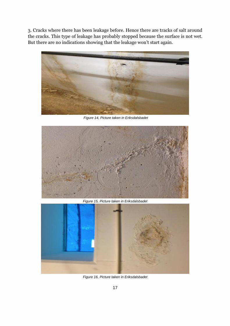
3. Cracks where there has been leakage before. Hence there are tracks of salt around
the cracks. This type of leakage has probably stopped because the surface is not wet.
But there are no indications showing that the leakage won’t start again.
Figure 14, Picture taken in Eriksdalsbadet
Figure 15, Picture taken in Eriksdalsbadet
Figure 16, Picture taken in Eriksdalsbadet

18
4. Cracks where there is continues leakage. There is salt around the cracks and the
surface is still wet.
Figure 17, Picture taken in Eriksdalsbadet
Figure 18, Picture taken in Eriksdalsbadet
Figure 19, Picture taken in Eriksdalsbadet

19
Figure 20, Picture taken in Eriksdalsbadet
Figure 21, Picture taken in Eriksdalsbadet
Figure 22, Picture taken in Eriksdalsbadet

20
Figure 23, Picture taken in Eriksdalsbadet
Figure 24, Picture taken in Enskedehallen
Figure 25, Picture taken in Enskedehallen

21
5. Missing concrete cracks. In this case, we can see the reinforcement bar and this is
the most severe and damaged cracks. On the last two pictures, here you can also
clearly see corrosion on the reinforcement. This is probably due to heavy leakage
from the pools, where the chloride and carbonation have been the larger factor for
the corrosion leading to these kinds of cracks.
Figure 26, Picture taken in Eriksdalsbadet
Figure 27, Picture taken in Eriksdalsbadet
Figure 28, Picture taken in Enskedehallen

22
Figure 29, Picture taken in Enskedehallen
Figure 30, Picture taken in Enskedehallen
Figure 31, Picture taken in Enskedehallen

23
4.235 Cracks due to chloride induced corrosion and carbonation
Since this report is about cracks in swimming facilities, chloride induced corrosion
and carbonation are factors that should be considered. Hence, apart from
mentioning these causes above, below this report studies chloride-induced corrosion
and carbonation in detail. In addition, in the solution section (4.3) there are methods
for treating corrosion and carbonation in concrete.
4.2341 Chloride-induced corrosion
Reinforcement within concrete constructions is usually in a passive state that is
caused by a high alkalinity (ph > 12.5). This makes the reinforcement protected from
corrosion. However, concrete in wet surroundings are affected by the aggressive
surrounding and because of this there are two factors that can break down the
passive state of the reinforcement. These factors are carbonation and chloride
ingress. (Sandell, 2015)
The mechanism of corrosion that is chloride-induced is a standard problem in
swimming facilities. Corrosion of reinforcement in concrete structures is something
that needs to be examined and repaired; otherwise it can lead to devastating load
capacity problems. When steel (reinforcement) is embedded, it develops a protective
passive layer and this layer is generated by itself due to the hydration of cement. A
thin layer on the surface of the metal that has undergone oxidation is called an oxide
film. The oxide film itself is a product of initial corrosion. In the early stages of
corrosion, a ferrous hydroxide (FeOH2) compound is formed. This hydroxide has low
solubility and when water and oxygen is present the compound oxidizes to iron oxide
(Fe2O3) which forms the passive film. As this film is being formed, the oxygen
diffusion is reduced leading to reduction of the corrosion rate. (T. Paul Teng, 2000)
If this layer is present the steel remains protected.
However, when chloride ions penetrate the concrete, the passive layer is destroyed.
After this process, in the presence of oxygen and water, corrosion occurs. (Neville,
1995)
According to “Betonghandbok (Material)”, surroundings where salt can penetrate the
concrete from the surface, the risk for corrosion is high. Thus, there should be high
requirements and demands on both material and when constructing the swimming
pools. An intact concrete gives a lower corrosion speed. This can be done by using
concrete with a low water-cement-ratio and additives. According to BBK 94 wet
surroundings with presence of salt are divided into two different environment
classes. These are aggressive reinforcement environment and extremely aggressive
reinforcement environment. The expected life span of these are also divided into two
classes. 50 years for class 1 and 100 years for class 2. In the table below there are
examples on what the equivalent water-cement-ratio should be, and what the cover
should be. (Christer Ljungkrantz, 1997)
24
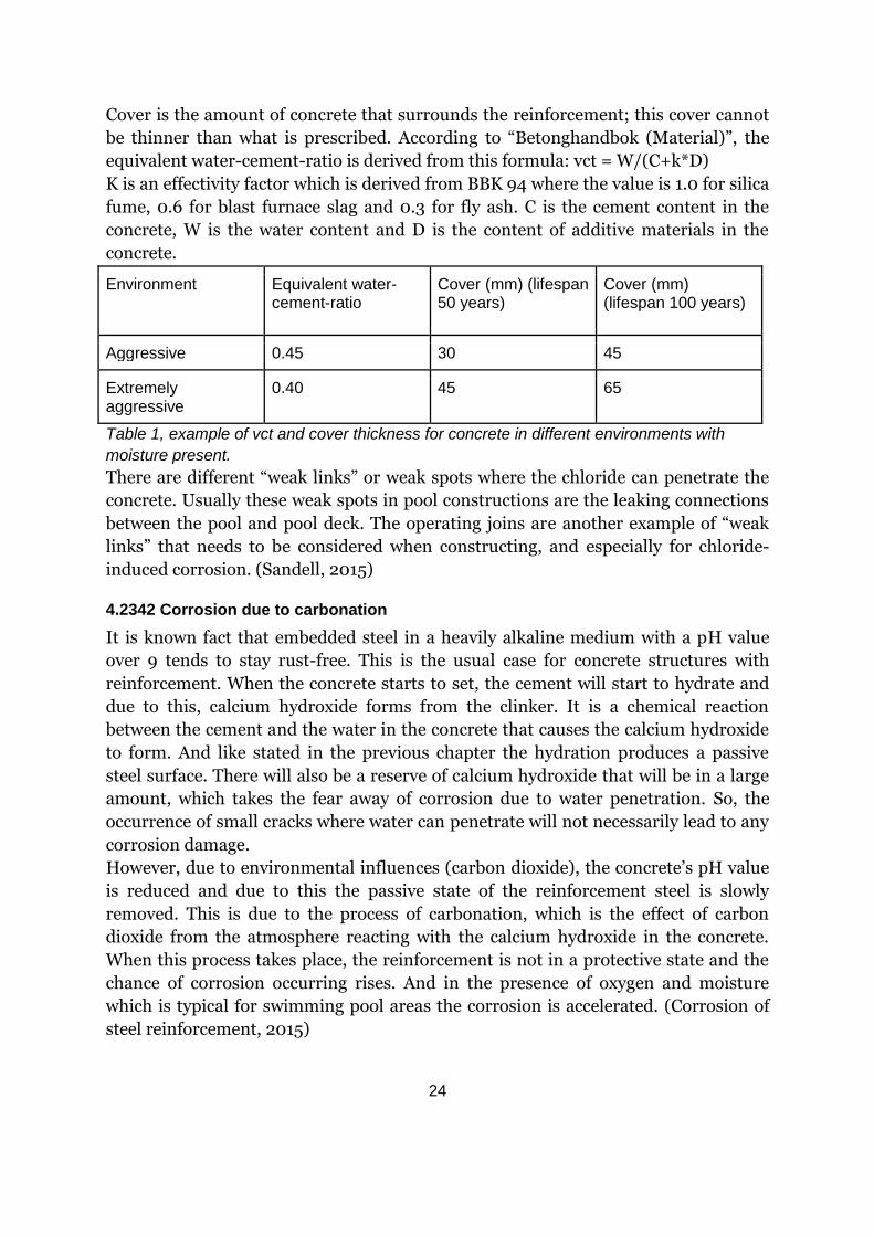
Cover is the amount of concrete that surrounds the reinforcement; this cover cannot
be thinner than what is prescribed. According to “Betonghandbok (Material)”, the
equivalent water-cement-ratio is derived from this formula: vct = W/(C+k*D)
K is an effectivity factor which is derived from BBK 94 where the value is 1.0 for silica
fume, 0.6 for blast furnace slag and 0.3 for fly ash. C is the cement content in the
concrete, W is the water content and D is the content of additive materials in the
concrete.
Environment Equivalent water-cement-ratio
Cover (mm) (lifespan 50 years)
Cover (mm) (lifespan 100 years)
Aggressive 0.45 30 45
Extremely aggressive
0.40 45 65
Table 1, example of vct and cover thickness for concrete in different environments with
moisture present.
There are different “weak links” or weak spots where the chloride can penetrate the
concrete. Usually these weak spots in pool constructions are the leaking connections
between the pool and pool deck. The operating joins are another example of “weak
links” that needs to be considered when constructing, and especially for chloride-
induced corrosion. (Sandell, 2015)
4.2342 Corrosion due to carbonation
It is known fact that embedded steel in a heavily alkaline medium with a pH value
over 9 tends to stay rust-free. This is the usual case for concrete structures with
reinforcement. When the concrete starts to set, the cement will start to hydrate and
due to this, calcium hydroxide forms from the clinker. It is a chemical reaction
between the cement and the water in the concrete that causes the calcium hydroxide
to form. And like stated in the previous chapter the hydration produces a passive
steel surface. There will also be a reserve of calcium hydroxide that will be in a large
amount, which takes the fear away of corrosion due to water penetration. So, the
occurrence of small cracks where water can penetrate will not necessarily lead to any
corrosion damage.
However, due to environmental influences (carbon dioxide), the concrete’s pH value
is reduced and due to this the passive state of the reinforcement steel is slowly
removed. This is due to the process of carbonation, which is the effect of carbon
dioxide from the atmosphere reacting with the calcium hydroxide in the concrete.
When this process takes place, the reinforcement is not in a protective state and the
chance of corrosion occurring rises. And in the presence of oxygen and moisture
which is typical for swimming pool areas the corrosion is accelerated. (Corrosion of
steel reinforcement, 2015)

25
4.2343 Damages to the concrete due to corrosion in the reinforcement
The factors that influence corrosion of the reinforcement in concrete are many but
the most obvious are: pH value, moisture level, oxygen, carbonation, chlorides,
quality of the construction materials and concrete, the cover to the reinforcement
and the formations of cracks. Corrosion due to chloride appears more than
carbonation, especially in a swimming hall basin where the water used contains
chloride. There is a typical process of how the damages to the concrete appear due to
corrosion of the reinforcement. Such a process is described below. (Corrosion of steel
reinforcement, 2015)
Stage 1 - Formation of white patches
If the concrete is permeable enough to allow water and carbon dioxide to penetrate
through the concrete, then carbonation which previously attack the surface of the
concrete, advances to the interior concrete. Then we have the process which is
described above where the carbon dioxide reacts with the calcium hydroxide and
forms calcium carbonate. With the water moving freely and carrying the calcium
carbonate to the surface, indications of white patches starts to appear. This is a sign
that indicates that carbonation has occurred inside the concrete.
Stage 2 - Brown patches along the reinforcement
When reinforcement has started to corrode due to the numerous reasons mentioned
above, especially chloride corrosion, brown products (a layer of ferric oxide) starts to
appear on the reinforcement surface. Along with the moisture in the concrete, this
brown product can break through and appear on the concrete surface. Usually this
stage accompanies cracking, or indicates that cracking in the concrete occurs shortly
after this process.
Stage 3 - Cracks starts to occur
When the reinforcement starts to corrode, the products that are created from
corrosion normally expands to between 6 to 10 times the volumes of the
reinforcement. Since they occupy a great amount of space inside the concrete, the
pressure of the volume expansion results in cracking. When you have a thin crack
line on the surface above the reinforcement, and the line is running parallel to the
reinforcement, it is a direct indication of possible reinforcement corrosion. These
cracks indicate that the rust from corrosion is expanding enough for the concrete to
crack. However, at this stage if the reinforcement would be investigated, it would
seem like it is rust free.
Stage 4 - Formation of multiple cracks
As the corrosion continues, several layers of ferric oxide on the reinforcement will
appear. This will in turn pose pressure on the concrete which will expand the existing
cracks. And in addition to this, several thin cracks will be formed. There will also be a
reduction of the bond between the concrete and the reinforcement. A way to test this
is when you tap the concrete surface with a light hammer; there will be a hollow
sound like plaster walls.

26
Stage 5 - Damage on the cover concrete
Due to the loose bonds between the concrete and the steel and in addition to this the
formation of several layers of scales, the cover concrete starts to loosen its grip. At
this phase, there is a reduction of the size of the steel bars.
Stage 6 - Steel bars starts to snap
With the previous stage continuing without any repair measures taken, the continued
reduction of the size of the bars results in snapping. At this stage, the main bars will
also have a considerable reduction in the size.
Stage 7 - Bars buckling and concrete bulging
Stage 5 and stage 6 leads to the main bars to buckle thus the concrete starts bulging
in that specific region where the main bars have been damaged. What follows is
enormous damage and collapse of the structure. (Corrosion of steel reinforcement,
2015)
4.3 Solutions
Looking at the cracks and their development in swimming facilities, one can
understand that these cracks need to be repaired as soon as possible. When doing a
visual inspection on the pictures from the swimming facilities that were visited, and
how damaging these cracks are to the structure we suggest that these cracks should
be examined and taken measures against as soon as possible. After reading all the
symptoms of cracks and how they appear, one can understand the severity of these
cracks and how damaging these cracks are. As mentioned above, not only is it the
width and the depth that plays a role, but also the movement of these cracks, how
they expand and in which direction. There are several methods for measuring cracks
but some of the most common methods are mentioned below:
4.31 Measurement of cracks
There are many ways for measuring the dimensions of cracks. Measuring the
dimensions of cracks is essential to know how severe and damaging the cracks are.
It is important to mention the necessity to use non-destructive testing. These
methods can be applied to both old and new structures without damaging the
structure. If destructive methods are used, for example, by removing cores for
compression testing, it can damage the entire construction. Usually non-destructive
methods for the concrete are used to locate and determine the dimensions of cracks.
Below, some of these methods are mentioned. The methods that are mentioned are
used for measuring the dimensions and the severity of cracks. (Perkins, 1997)
27
4.311 Visual inspection
Visual inspection should always be the first stage. An experienced engineer within
concrete structures may be able to determine the causes and extent of cracks by only
observing. A visual inspection can also be used as the first step to determine which
cracks are the most severe cracks so that the measurements can be done on those
cracks first. (Perkins, 1997)
4.312 Width of cracks
Measuring the width of cracks that appear on surface can be done by using a simple
comparator. The comparator consists of a plastic strip and it has fixed lines that
represent the width. Alternatively, a hand-held microscope can also be used with a
suitable scale. These are some easy methods to use the width of cracks are used
world-wide.
There are also ways of measuring if the cracks are still moving. The width of the
cracks can expand due to temperature changes or to early thermal contraction.
4.313 Movement of cracks
If one would like to measure “movement” of the cracks or expansion of the cracks
then it can be done by putting tell-tales bonds across the cracks, and this will show if
movement takes place. (Society, 2016)
If further measurements are required to study the crack movements, then a
mechanical strain gauge (DEMEC) can be used. DEMEC consists of a digital dial
gauge or standard gauge attached to an invar bar. A fixed point that is conical is set at
one end of the invar bar. Another moving point that is conical is set on a knife edge
pivot at the opposite end. The pivoting movement of the second point is measured by
the gauge. Then a setting out bar is used to put steel discs with holes in position
which will be attached to the concrete by using acceptable adhesive. Each time a
reading is made, the conical points are inserted into the holes in the discs and then
the reading of the gauge is observed. If there is any form of strain change in the
structure will lead to a change in the reading of the gauge. And then there are
software program which the readings can be inserted in which will calculate the
strain changes. A picture showing the different parts described above is shown below.
(Association, 2017)

28
Figure 32, Demec gauge instrument (Association, 2017)
4.314 Ultrasonic testing for depth of cracks
Ultrasonic testing is performed by sending high-frequency waves (over 20 kHz)
through the concrete. The background for this testing is based on the principle that
waves travels faster through denser media than looser media. So by following this
principle the testers can interpret the quality of the concrete by reading the different
velocity of the wave.
The method is fairly simple if one understands the reading. Two transducers are used
sending and receiving frequency (Ultrasonic Test for Concrete, 2015).These
transducers are set in each side of the crack, one working as a transmitter and one
working as a receiver. Usually some sort of thin grease layer is applied to the surface
of the concrete in order to ensure an effective transfer of the waves between the
transducers and the concrete. The transducers are also set in two different distances
between each other with the surface crack in the middle two get better reading. This
method is good as it is a non-destructive method for measuring depth of surface
cracks. However, there are some factors than can disturb the measurements from
this process. Below are some of these factors mentioned: (Perkins, 1997)
• Moving cracks can sometimes move outside of the transducers measuring
field. When this happens, the instrument thinks that the movement of the
cracks has stopped when in case it continues outside of the measuring field.
• The moisture content in the concrete can affect the results a lot and due to
this, ultrasonic testing is usually used on dry concrete.
• The reinforcement can disturb the sound waves leading to unreliable
measurements.
It is important to know whether the cracks are filled with water or not. With this
knowledge one can calibrate the instruments so it will give better results.
29
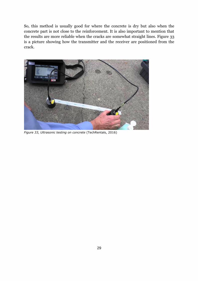
So, this method is usually good for where the concrete is dry but also when the
concrete part is not close to the reinforcement. It is also important to mention that
the results are more reliable when the cracks are somewhat straight lines. Figure 33
is a picture showing how the transmitter and the receiver are positioned from the
crack.
Figure 33, Ultrasonic testing on concrete (TechRentals, 2016)
30
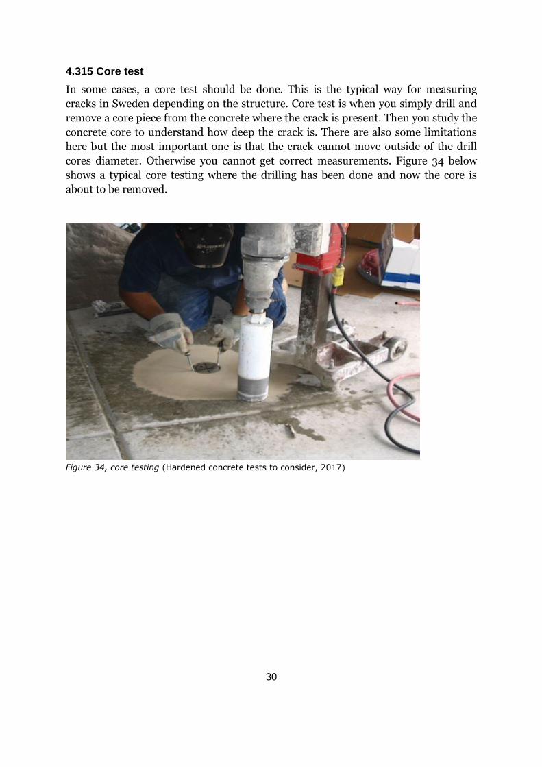
4.315 Core test
In some cases, a core test should be done. This is the typical way for measuring
cracks in Sweden depending on the structure. Core test is when you simply drill and
remove a core piece from the concrete where the crack is present. Then you study the
concrete core to understand how deep the crack is. There are also some limitations
here but the most important one is that the crack cannot move outside of the drill
cores diameter. Otherwise you cannot get correct measurements. Figure 34 below
shows a typical core testing where the drilling has been done and now the core is
about to be removed.
Figure 34, core testing (Hardened concrete tests to consider, 2017)
31
4.32 Methods for repairing cracks and corrosion
Cracks in a basin can be detected by a water filling test of the shell construction. For
finer cracks, which are up to 0.1 mm, when exposed to water, autogenously healing
can take place. This self-healing process is chemical, mechanical and physical. In the
physical process, the hardened cement paste expands. In the chemical process, the
development of calcium carbonate with an increased volume has the best effect. The
mechanical process can be explained as, when the rainwater flows through the
streets and picks up material on the way. So basically, the mechanical process is
when the water transports loose material in the concrete to the cracks to fill up the
narrow spots. Studies shows that crack with the width of 0.1 mm can be repaired by
the three processes mentioned above. Cracks that are wider must be injected. (Repair
of cracks, 2017)
4.321 Classification of the repairing methods for cracks
There are several injection materials and they are classified depending on their
composition. They are listed below:
• Epoxy
• Gels
• Hydraulic binders
• Polyurethane
They are also classified depending on their functions:
• Force transmitting
• Ductile filling
• Swelling filling
4.322 Repair of cracks in concrete by using Epoxy and Polyurethane injection
resins
Concrete that is based on hydraulic binders such as standard Portland cement, have
a tendency to crack. As we mentioned above there are many different types of cracks
and the causes for these cracks come in even more different ways. In some cases, the
cracks are small, and in these cases the cracks can be ignored since they are able to
go through the self-healing processes that are mentioned above. But when cracks
start to expand and penetrate deeper in the concrete, it starts to affect the service life
time of the concrete. This creates a need to repair these cracks with proper materials
and strategies. We also mentioned some ways to tend these cracks but the most
efficient and effective methods are crack injection using either epoxy resin or
polyurethane resin based grouts. Although these techniques have existed for a long
time, the materials used in these techniques have been getting more refined and
better for some time now. (Repair of cracks, 2017)
32
4.3221 Materials and considerations
In order to decide whether crack injection should be used, it is important to study the
cracking in a particular place or structure in detail. There may be many reasons why
the cracks have appeared. The investigators need to know if the cause is drying
shrinkage cracking, cracking due to corrosion for example if alkali aggregate
reactions are involved.
Further, there is a need to understand whether the crack is structural or non-
structural, i.e. on an element that is non-load bearing. Also like mentioned above,
some cracks may still be developing. There are cracks that move or expand in
different directions. Some are due to settlements or due to damages. There are many
different types of cracks and such must be studied so that the best possible repair
method can be used. When cracks are subjected to subsequent movement, an epoxy
repair method may not be suitable. Low viscosity epoxy resins and polyurethane
resins will be discussed in this section. Where the epoxy resins are mainly used for
structural crack repair and polyurethane used for mainly where movement is
expected or water leakages needs to be stopped. Sometimes a combination of these
two materials is a good solution.
Both Epoxy resins and polyurethanes are sensitive to water. Epoxy resins have some
difficulties in setting and developing the desired strength, when water is present.
Some epoxy resin systems are tolerant to a decent amount of damp, and some are
used in water. In addition, handling epoxy injection resins underwater could prove to
be more difficult and more expensive than polyurethane resins. On the other hand,
polyurethane resins are available in one or several pack systems. One pack resins
usually act like foam when water is present, hence it will stop the flow of water in
cracks rather quickly. When several pack systems are used, they offer either a flexible
sealing solution or foam like solution. The foam that is generated by using a several
pack systems is generally more flexible. (Repair of cracks, 2017)
4.3222 Structural crack repair using epoxy resins
This procedure is dependent on the application and the location of the cracks.
Vertical, horizontal and overhead cracks require approaches that are different to each
other. Another consideration is the size and the accessibility of the cracks. Depending
on these requirements, crack repaired by epoxy injections can restore the structural
characteristics and reduce moisture penetration through the concrete cracks, from to
0.05 mm in width and greater.
4.3223 Preparation for the surface
Like all procedures, preparation is the key. For repair processes the preparation on
the surface area is the key for injection. Depending on the condition and location of
the cracks, all foreign materials and loose or damaged concrete must be removed. It
is necessary that the surface where the injections take place is strong and be able to
33
handle to the pressure of the injected resin. In addition, sealing of the crack surface
must be proper as it is necessary to avoid losses and damages during injections.
4.3224 Repair procedure
The equipment that is used for injection is an air assisted gun, hand actuated delivery
systems and spring or balloon actuated capsules.
The procedure begins with installing the injection ports with a proper spacing of
generally 40 mm from the center of each port. Wider cracks may require wider
spacing. The cracks are then sealed through their length with a suitable sealing
material. If the inspected crack penetrates through an entire section of concrete then
both sides of the concrete must be sealed for the best outcome and effect of the
injection. Epoxy, polyester, cement and silicone based materials may be used for this
purpose. After this process, injections are carried out with the cap seal set. On the
horizontal areas, the injection should start at the widest sections. Vertical cracks are
injection from the bottom of the structure to the top. Usually, cracks are injected
until the material flows out from the ports. Smaller cracks also require higher
pressure since they tend to be more difficult to penetrate through.
Once the injection is complete, the ports can be removed. The cap seal may also be
removed using procedures such as grinding or they can remain if they do not
interfere.
To verify that this process has succeeded, cores at suitable areas needs be taken out,
as mentioned above in core test (see section 4.315). Non-destructive testing is also a
type of verifying process that should take place after the epoxy injection have been
done, like an ultrasonic test. (see section 4.314).
4.3225 Non-structural crack repair using polyurethane resins
When the crack does not compromise the structural characteristics, then an injection
with polyurethane grouts or other non-structural materials may be more suitable. As
discussed above, generally two types of polyurethane materials are used. One system
for sealing dry cracks and the other one is used for stopping water flowing through
the cracks. Both single and several pack systems may be used for generating foam, as
mentioned above. The process is quick and the foam takes form in usually less than a
few seconds. When using several pack systems of polyurethane, multicomponent
guns are used depending on the reaction time. It is important to mention that mixing
and delivering materials must be properly controlled. The procedure is similar to the
epoxy injection procedure just a change in the material injected.

34
4.323 Methods for extracting chloride and measuring chloride level in concrete
4.3231 Electrochemical chloride extraction (ECE)
ECE is a process to increase the pH value in a concrete structure, in addition
preventing corrosion in the reinforcement or reducing the corrosion level to an
accepted level.
The method generally works by applying high current density for a short period of
time, typically a couple of weeks. The reinforcement in the concrete will act as the
cathode and an anode will then be placed in an electrolyte near the concrete surface.
The positive terminal will then be connected to the secondary anode and the negative
terminal will be connected to the reinforcement. This will make the steel to achieve a
negative polarity which means it will repulse anions and attract cations that exists in
the concrete pore solution. These will act as an electrolyte which makes it possible for
current to move between anode and the cathode.
So succinctly, ECE is a method for treating reinforced concrete that has already
suffered or is about to suffer from chloride-induced corrosion.
Chemically speaking, the negatively charged chlorides will be pulling towards the
positive pole. With a high voltage, the chloride will migrate out of concrete. With the
process of chloride migrating, simultaneously there will be a production of hydroxyl
ions which will result to an increased pH-value around the reinforcement. After
reducing the chloride level the voltage will be turned off. This is where the
reinforcement wants to be in a chloride-free alkaline surrounding which results in a
strong passivation of the steel. This alkaline environment will protect the steel
against future corrosion. It is also important to mention that ECE does not replace
already corroded steel. Another limitation that ECE has is that the reinforcing (steel)
must be electrically continuous for the process to succeed. The figure below gives a
general understanding of the process, where the steel is the reinforcement in the
concrete which is working as a cathode. Below is an illustration of the method:
Figure 35, Figure explaining how ECE-process works (Broomfield J. P., 2017)
35
This process has been applied to structures like highway structures and car parks, in Europe
and North America. (Jan Lindland, 2004)
4.3232 Measurement of chloride level
Measurements of chloride content in concrete can be done in several ways. The most
common method is to take out concrete from different levels and the chloride profile
is determined by analysis of chloride content with a titration method. You can also
measure the state of the corrosion with non-destructive methods. The method is
called RapiCore (between 5 to 10 seconds of measurements). With this method, you
can get results for the potential of the corrosion, the speed of the corrosion and the
concrete resistivity.
Another method is to perform a core test. This test is described above as for
measuring and analyzing a concrete section. The chloride level in this concrete
section can also be tested. You take out a core between 4-5 cm in depth and 1cm in
diameter, and it is sent to the laboratory and tested for chloride, for each cm depth.
4.324 Method for minimizing carbonation
Due to carbonation, the reinforcement concrete structure can start to show signs of
damage much earlier than the expected service life. Previously, the most common
repair method for increasing the service life of concrete structures with
reinforcement that has been damaged by carbonation has been to replace elements
or remove contaminated concrete sections. Usually it has been replaced by steel plate
bonding or some form of installation of additional supports. However, these
procedures are way too expensive and questionable for the sustainability of the
repair. Removal of concrete sections can cause problems to the entire structure.
Until recently, these procedures have been the dominating repair methods. Now we
have an alternative method that is non-destructive, called the electrochemical
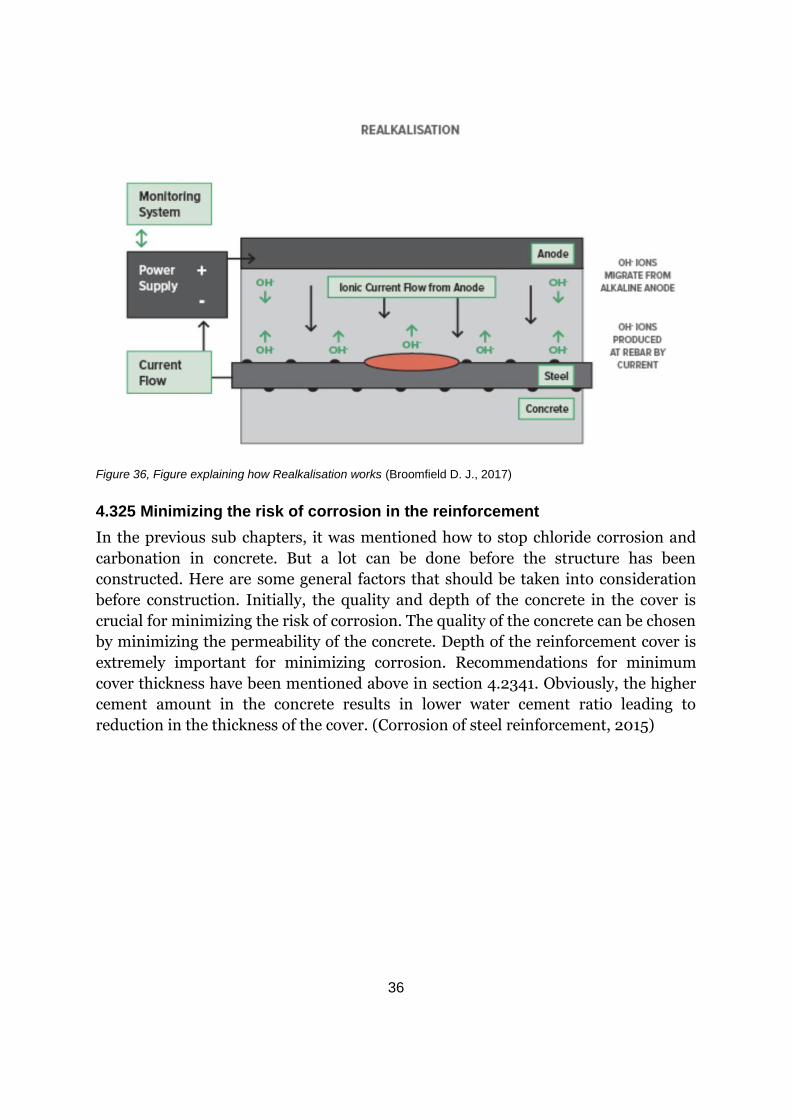
realkalisation (RE). (Gonzalez, 2011)
The method for realkalisation is described as the equivalent of ECE, which is
described in section 4.4. This process is a shorter treatment than ECE, usually days
instead of weeks. The system uses a calcium carbonate electrolyte to help the
regeneration of the alkalinity in the concrete. The process is the same as ECE, as the
same anode systems are used. The problem with this process is that the pH of
calcium carbonate is not far above the pH for the corrosion threshold. (Broomfield D.
J., 2017)
Figure 36 illustrates this method.
36
Figure 36, Figure explaining how Realkalisation works (Broomfield D. J., 2017)
4.325 Minimizing the risk of corrosion in the reinforcement
In the previous sub chapters, it was mentioned how to stop chloride corrosion and
carbonation in concrete. But a lot can be done before the structure has been
constructed. Here are some general factors that should be taken into consideration
before construction. Initially, the quality and depth of the concrete in the cover is
crucial for minimizing the risk of corrosion. The quality of the concrete can be chosen
by minimizing the permeability of the concrete. Depth of the reinforcement cover is
extremely important for minimizing corrosion. Recommendations for minimum
cover thickness have been mentioned above in section 4.2341. Obviously, the higher
cement amount in the concrete results in lower water cement ratio leading to
reduction in the thickness of the cover. (Corrosion of steel reinforcement, 2015)

37
6. Discussion
Swimming pool facilities are generally highly affected by the environment as we
mentioned above. Due to direct contact with water with chloride, and carbonation,
maintenance on these kinds of structures is highly needed. The execution of the
casting process needs be thorough; otherwise the structure can take larger damages
and cause high subsequent costs. In this project, cracks have been studied and
different repair methods have been mentioned specifically for these cracks. As for all
structures, stronger regulations in monitoring during the construction phase will
provide quality functions and bring improvements to similar facilities. It is important
to consider the relation between higher investment costs, higher quality and
sustainability. After studying these facilities and looking at Eriksdalsbadet which is
only about 20 years old, we agree that high investment should be made from the
start, to reduce repair costs. By higher investment we mean, production, processing
of concrete, casting…etc. These needs to be monitored and performed with caution,
and in this way the best possible facilities will be provided, and the service life of
swimming pools will be extended.
From visiting the facilities, especially with Dennis Lundgren from CBI, we learnt a lot
about how a visual inspection is performed. From the pictures, Enskedehallen needs
to be repaired immediately, since it is an older structure. We were also surprised by
how easy one can just by knocking on cracks, find out or get an understand of
whether a crack is deep or not. The trick is to look for hollow sounds. Obviously, this
requires experience just like the visual inspection does. In addition, we noticed that
the concrete that is not a part of the basin in Enskedehallen seems to be much
healthier. Maybe, they have been treated differently, or maybe it has a lot to do with
the swimming pool water. We assume that the healthier concrete has been less in
touch with chloride then the basin concrete.
After the visit with Lundgren from CBI we also saw that in some places of both
constructions, there are reinforcement bars very close to the sides of the walls. So,
either the cover thickness has not been considered or there have been some damages
that have reduced the thickness (look at picture 8 in appendix).
We strongly recommend that the smaller cracks should be examined in
Eriksdalsbadet, because they may be deeper that what is thought. And this cannot be
determined with just a visual inspection. Because like mentioned above, since a crack
can be very thin on the surface, it does not mean that the crack is deep inside the
concrete. By knocking on cracks, you find out if you may have a deep crack or not.
But to find out how deep the crack really is, there are different methods as mentioned
in this thesis, such as ultra-sonic testing or a core test. Also, there are many causes
for cracks to appear and by measuring cracks from time to time, we can determine if

38
the causes are repaired or not. There are different methods to detect whether
corrosion has occurred or not, and it does not cost very much to examine concrete.
In could be the reason why Enskedehallen looks damaged, and the cracks that we
could see in Enskedehallen are probably mainly caused by corrosion. Joints are also
very important to consider. We have noticed in Eriksdalsbadet that there is leakage
from the casting joints around the basin. We assume that when the workers try to put
the rubber in the joins to avoid water leakage, they were not careful enough with
putting the protection or rubber. Look at picture 13 in the report from Lundgren
from CBI. There is a clear example for leakage from casting joints.
Another consideration is to decrease the chloride level in the swimming water.
Chloride is put into swimming water to reduce bacteria level, but there are other
ways to kill bacteria. Studies show that blue light at 405 to 470 nm is bactericidal.
There are also studies that purple light can also reduce bacteria level in the water. So,
by installing blue or purple lights, one can reduce the chloride level in the water. By
reducing the chloride level in the swimming water, we think that it could be a
possibility for minimizing the risk for corrosion. Obviously, a lot of studies should be
carried out before blue or purple light can substitute the chloride in the water.
There is an interesting article from Laser Therapy about this. (Lubart, 2011).
There are also other methods for reducing leakage through the concrete cracks, for
example by placing PVC cloth inside the swimming basin. In this way, we can avoid
the chloride in the water from damaging the reinforcement and avoid corrosion.
However, this method is aesthetically not preferred because usually swimming pools
are cover with ceramics. If PVC cloth is used, it is difficult to have a swimming pool
with white tiles as it is usually preferred.
To conclude this thesis, our advice is to pay more attention of the workers during
casting. It is also important to manage cracks from the beginning and not postpone
examinations until damages appear, and perform measurements on cracks
frequently to see if the factors that causes the cracks are fully repaired.
39
7. Conclusion
After doing research for this thesis we have learnt:
• That cracking is a phenomenon that often occurs in concrete.
• That corrosion in reinforcement plays an important role when it comes to
forming and expanding cracks.
• That there are many methods for figuring out what the cause is for a crack,
however, it can also be determined by just studying the shape of the crack.
• That the resources needed for investigating and repairing cracks is
underestimated.
• That cracks can lead to devastating structure problems and should not be
taken lightly
8. Future Studies
Something that should be studied is how the concrete quality today is compared to
how the concrete quality was in the past. From personal experience, we have noticed
that concrete that was used for structures that were built 50-60 years ago, are harder
to remove, than concrete from 10-20 years ago. During demolition of old concrete
structures in Iraq we noticed that the concrete was strong and much harder than
concrete in structures from 10-20 years ago. Perhaps the reason is due to the
increase of salinity in different places around the world. Perhaps the salt level in
concrete affects the strength of the concrete. Or perhaps it is something just in the
concrete in Iraq.
We encourage that furthered researches are performed so the quality of concrete can
increase, and by doing so, increasing the service life of constructions.
40
7. References
A.M, N. a. (2005). Concrete Technology. NewYork.
Association, B. C. (2017). Retrieved April 19, 2017, from www.mastrad.com:
http://www.mastrad.com/demecsg.htm
Australia, C. a. (1978, May). Design of concrete structures for serviceability.
Bergström, S. G. (1987). Betong Handbok. Stockholm, Sverige: Svenskt Tryck AB.
Broomfield, D. J. (2017). Realkalisation. Retrieved April 19, 2017, from
www.jpbroomfield.co.uk: http://www.jpbroomfield.co.uk/pages/realkalisation.php
Broomfield, J. P. (2017). Electrochemical Chloride Extraction. Retrieved April 19, 2017, from
www.jpbroomfield.co.uk: http://www.jpbroomfield.co.uk/pages/electrochemical-
chloride-extraction.php
Christer Ljungkrantz, G. M. (1997). Betonghandbok. Stockholm: Svenskt Tryck AB.
Concretesask. (2017). Retrieved April 19, 2017, from www.concretesask.org:
http://www.concretesask.org/resources/why-is-concrete-better
Corrosion of steel reinforcement in concrete- causes and damages to concrete. (2015).
Retrieved April 19, 2017, from www.theconstructor.org:
https://theconstructor.org/concrete/corrosion-steel-reinforcement-concrete/6179/
Dailycivil. (2017, January 17). Water cement ratio. Retrieved April 25, 2017, from
www.dailycivil.com: http://www.dailycivil.com/water-cement-ratio/
Gharpedia. (2016). Retrieved April 19, 2017, from www.gharpedia.com:
https://gharpedia.com/major-causes-influences-cracks-building/
Gonzalez, F. (2011). Electrochemical Realkalisation of Carbonated Concrete. International
Journal of Electrochemical Science, 6332-6349.
Hardened concrete tests to consider. (2017). Retrieved April 19, 2017, from
www.concretenetwork.com: https://www.concretenetwork.com/concrete-
testing/considerations.html
Jan Lindland, S. a. (2004). Veiledning i metoder for utbedring av karbonatisert betong i
verneverdige bygninger.
Murray, G. B. (1978). Thermal and shrinkage cracking in reinforced concrete.
Neville, A. (1995). Material and Structures. London.
Party, C. S. (1992). Non-structural cracks in concrete - third edition. The Concrete Society.
Perkins, P. H. (1997). Repair, Protection and Waterproofing of Concrete Structures, Third
edition. London: Taylor and Francis Group.
Repair of cracks. (2017). Retrieved April 19, 2017, from www.nbmc.com:
http://www.nbmcw.com/chemicals-admixtures-additives/29899-repair-of-cracks-in-
concrete-by-using-epoxy-and-polyurethane-injection-resins.html
Sandell, C. (2015). Förstudie, Vattenpalatset, Lerums kommun. Göteborg: Tellstedt.
Shetty, M. S. (December). Concrete Technology Theory and Practice. New Delhi: S. Chand
publishing.
Society, T. C. (2016). Retrieved April 19, 2017, from www.concrete.org.uk:
http://www.concrete.org.uk/fingertips-nuggets.asp?cmd=display&id=464

41
TechRentals (Director). (2016). Determine Concrete Crack Depth using the Proceq PL-
200PE [Motion Picture].
Types of cracks in reinforced concrete slabs. (2015). Retrieved April 19, 2017, from
www.theconstructor.org: https://theconstructor.org/concrete/types-of-cracks-in-
reinforced-concrete-slabs/5941
Ultrasonic Test for Concrete. (2015). Retrieved April 19, 2017, from www.theconstructor.org:
https://theconstructor.org/concrete/ultrasonic-test-on-concrete/2847/

42
8. Appendix
The next pages consist of the report from Dennis Lundgren from CBI. Where he discusses
what was done in our second visit and what his opinion is on some of the cracks that we
visually examined.
Kontaktperson RISE: Datum Beteckning Sida
Dennis Lundgren 2017-05-18 7P00394 1 (3) Utredningar
010-516 68 75
Er referens:
Folke Björk
Kungliga Tekniska Högskolan
Avd. för Byggnadsteknik
100 44 Stockholm
PM Sprickor i bassängkonstruktioner, Eriksdalsbadet och Enskedebadet (1 bilaga)
RISE CBI Betonginstitutet AB
Postadress Besöksadress Telefon E-post / Internet Org.nummer
Drottning Kristinas väg 26 100 44 STOCKHOLM
Drottning Kristinas väg 26 114 28 STOCKHOLM
010-516 68 00 [email protected] www.ri.se
556352-5699
1 Bakgrund och Uppdrag
På uppdrag av KTH har CBI Betonginstitutet undersökt sprickor i tre bassängkonstruktioner i
samband med ett examensarbete. Bassängerna som undersökts är ”Stora bassängen” och
”Djupa bassängen” i Eriksdalsbadet och bassängen i Enskedehallen. Undersökningen har
utförts okulärt och översiktligt. Syftet med uppdraget är att bedöma sprickornas art.
Bassängernas tillstånd och orsaken till sprickorna behandlas ej.
2 Beskrivning av objekten
Eriksdalsbadet byggdes i slutet av 1990-talet.
Enskedehallen byggdes ca år 1960.
2.1 Dokumentation
Ingen dokumentation har tillhandahållits.
3 Allmänt om skador på simbassänger
Läckage, armeringskorrosion och sprickbildning i betongen är vanligt förekommande skador i
simbassänger och badanläggningar från 1960- och 1970-talen.
Armeringskorrosion kan orsakas av huvudsakligen två saker, betongens karbonatisering och
förekomst av klorider i betongen. Karbonatisering, som kan sägas vara ett naturligt åldrande
hos betong, innebär att alkaliska komponenter i betongen reagerar med luftens koldioxid,
varvid betongens pH-värde sjunker och den ursprungliga rostskyddande förmågan hos
betongen därmed går förlorad.
Om betongen tillförs klorider i viss mängd kan dessa också sätta igång armeringskorrosion,
även om ingen karbonatisering skett. I simbassänger exponeras betongen ofta för klorider
genom att badvattnet neutraliseras med saltsyra. Klorider kan också från början vara ingjutna i
betongen.
Om betongen karbonatiseras in till armeringen eller om kloridhalten vid armeringen uppnår
kritiskt värde börjar armeringen rosta, om betongen är fuktig och det finns tillgång till syre. I
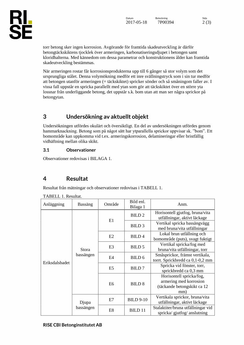
Datum Beteckning Sida
2017-05-18 7P00394 2 (3)
RISE CBI Betonginstitutet AB
torr betong sker ingen korrosion. Avgörande för framtida skadeutveckling är därför
betongtäckskiktens tjocklek över armeringen, karbonatiseringsdjupet i betongen samt
kloridhalterna. Med kännedom om dessa parametrar och konstruktionens ålder kan framtida
skadeutveckling bestämmas.
När armeringen rostar får korrosionsprodukterna upp till 6 gånger så stor volym som det
ursprungliga stålet. Denna volymökning medför ett inre svällningstryck som i sin tur medför
att betongen utanför armeringen (= täckskiktet) spricker sönder och så småningom faller av. I
vissa fall uppstår en spricka parallellt med ytan som gör att täckskiktet över en större yta
lossnar från underliggande betong, det uppstår s.k. bom utan att man ser några sprickor på
betongytan.
3 Undersökning av aktuellt objekt
Undersökningen utfördes okulärt och översiktligt. En del av undersökningen utfördes genom
hammarknackning. Betong som på något sätt har ytparallella sprickor uppvisar sk. ”bom”. Ett
bomområde kan uppkomma vid t.ex. armeringskorrosion, delamineringar eller bristfällig
vidhäftning mellan olika skikt.
3.1 Observationer
Observationer redovisas i BILAGA 1.
4 Resultat
Resultat från mätningar och observationer redovisas i TABELL 1.
TABELL 1. Resultat.
Anläggning Bassäng Område Bild enl.
Bilaga 1 Anm.
Eriksdalsbadet
Stora
bassängen
E1
BILD 2 Horisontell gjutfog, bruna/vita
utfällningar, aktivt läckage
BILD 3 Vertikal spricka bassängvägg
med bruna/vita utfällningar
E2 BILD 4 Lokal brun utfällning och
bomområde (puts), svagt fuktigt
E3 BILD 5 Vertikal spricka/fog med
bruna/vita utfällningar, torr
E4 BILD 6 Småsprickor, främst vertikala,
torrt. Sprickbredd ca 0,1-0,2 mm
E5 BILD 7 Spricka vid fönster, torr,
sprickbredd ca 0,3 mm
E6 BILD 8
Horisontell spricka/fog,
armering med korrosion
(täckande betongskikt ca 12
mm)
Djupa
bassängen
E7 BILD 9-10 Vertikala sprickor, bruna/vita
utfällningar, aktivt läckage
E8 BILD 11 Stalaktiter/bruna utfällningar vid
spricka/ gjutfog/ anslutning

Datum Beteckning Sida
2017-05-18 7P00394 3 (3)
RISE CBI Betonginstitutet AB
Anläggning Bassäng Område Bild enl.
Bilaga 1 Anm.
mellan två konstruktionsdelar.
Aktivt läckage längst större
delar av kortsidan
E9 BILD 12 Vertikal spricka, bredd ca 0,2-
0,3 mm, torr.
E10 BILD 13
Stalaktiter/bruna utfällningar vid
spricka/ gjutfog/ anslutning
mellan två konstruktionsdelar.
Enskedehallen -
Undersida BILD 14
Omfattande vita/bruna
utfällningar på undersidan samt
anslutning mot vägg. Aktivt
läckage.
Kortsida BILD 15 Aktivt läckage,
armeringskorrosion, bruna och
vita utfällningar.
Långsida BILD 16
Kortsida BILD 17
Kortsida BILD 18
5 Diskussion
Bruna utfällningar kan vara tecken på korrosion men kan även vara en anrikning av
föroreningar från bassängvattnet. De vita utfällningarna som observerats brukar vara
kalkutfällningar, och i det här fallet sannolikt även i kombination med en viss mängd klorider.
Sprickor med aktivt läckage är nästan alltid genomgående. Läckage kan även ske genom andra
otätheter som t.ex. gjutfogar och i anslutning mellan konstruktionsdelar. Sprickor med
kalkutfällningar som är torra är sannolikt också genomgående men har självläkt. Vattenförande
sprickor upp till en viss sprickbredd kommer med tiden att självläka. Torra sprickor behöver
inte vara genomgående för aktuell miljö. Saknas tätskikt är torra sprickor sannolikt inte
genomgående. Bassängerna i Eriksdalsbadet har dock eventuellt ett invändigt tätskikt.
För bassängväggar gäller exponeringsklass XD2 (korrosion orsakad av andra klorider än från
havsvatten) enligt gällande dimensioneringsregler. Acceptabel sprickbredd för nya
konstruktioner anges till 0,2-0,3 mm, beroende på livslängdsklass. För sprickor som är torra är
dock en sprickbredd på 0,3 mm inget som påverkar livslängen. Sprickor med aktivt läckage
bör tätas för att bromsa skadeutvecklingen. Förutom att läckaget kan orsaka korrosion på
armering som korsar sprickan medför även läckaget en kloridexponering över en större yta.
Den förhållandevis torra betongen på bassängens utsida suger kloridhaltigt vatten kapillärt som
anrikas och på sikt orsakar armeringskorrosion. Jämförs t.ex. BILD 7 och 9 med BILD 15-18
syns en tydligt skillnad i skadeutvecklingen för samma typ av konstruktion med åldern ca 20
respektive 50 år.
RISE CBI Betonginstitutet AB Utredningar
__SSignature_2
Dennis Lundgren

Datum Beteckning Sida
2017-05-18 7P00394 1 (9)
Bilaga 1
RISE CBI Betonginstitutet AB
Bilder
BILD 1. Översiktsbild, område E1.
BILD 2. Område E1 (bakom röret), horisontell fog/spricka.
Spricka, forts.
på BILD 3

Datum Beteckning Sida
2017-05-18 7P00394 2 (9)
Bilaga 1
RISE CBI Betonginstitutet AB
BILD 3. Område E1, vertikal spricka.
BILD 4. Område E2, brun utfällning och bomområde (puts).
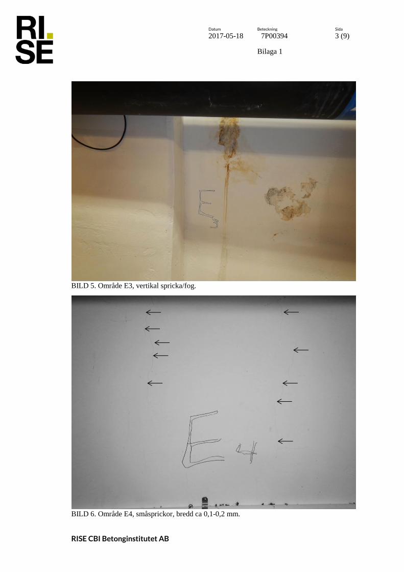
Datum Beteckning Sida
2017-05-18 7P00394 3 (9)
Bilaga 1
RISE CBI Betonginstitutet AB
BILD 5. Område E3, vertikal spricka/fog.
BILD 6. Område E4, småsprickor, bredd ca 0,1-0,2 mm.

Datum Beteckning Sida
2017-05-18 7P00394 4 (9)
Bilaga 1
RISE CBI Betonginstitutet AB
BILD 7. Område E5, spricka, bredd ca 0,3 mm.
BILD 8. Område E6, spricka/fog, korrosion på armering med täckskikt 12 mm.
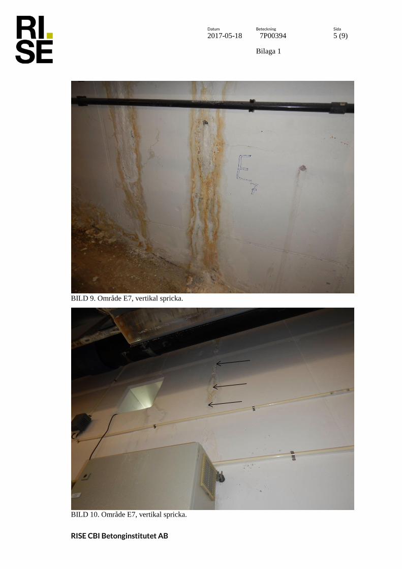
Datum Beteckning Sida
2017-05-18 7P00394 5 (9)
Bilaga 1
RISE CBI Betonginstitutet AB
BILD 9. Område E7, vertikal spricka.
BILD 10. Område E7, vertikal spricka.
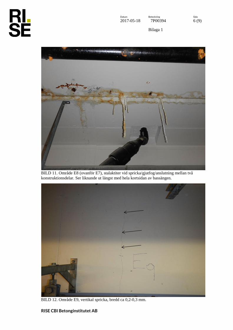
Datum Beteckning Sida
2017-05-18 7P00394 6 (9)
Bilaga 1
RISE CBI Betonginstitutet AB
BILD 11. Område E8 (ovanför E7), stalaktiter vid spricka/gjutfog/anslutning mellan två
konstruktionsdelar. Ser liknande ut längst med hela kortsidan av bassängen.
BILD 12. Område E9, vertikal spricka, bredd ca 0,2-0,3 mm.

Datum Beteckning Sida
2017-05-18 7P00394 7 (9)
Bilaga 1
RISE CBI Betonginstitutet AB
BILD 13. Område E10, stalaktiter vid spricka/gjutfog/anslutning mellan två
konstruktionsdelar.
BILD 14. Undersida bassäng Enskedehallen.
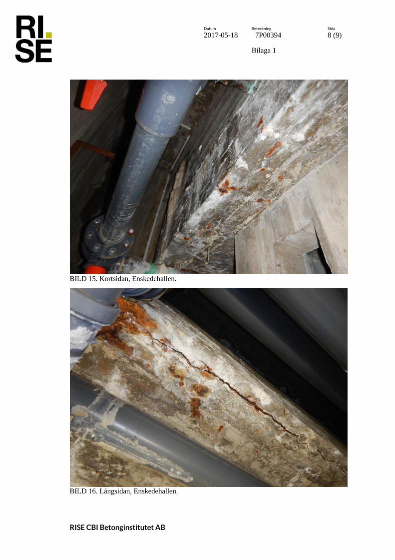
Datum Beteckning Sida
2017-05-18 7P00394 8 (9)
Bilaga 1
RISE CBI Betonginstitutet AB
BILD 15. Kortsidan, Enskedehallen.
BILD 16. Långsidan, Enskedehallen.

Datum Beteckning Sida
2017-05-18 7P00394 9 (9)
Bilaga 1
RISE CBI Betonginstitutet AB
BILD 17. Kortsidan, Enskedehallen.
BILD 18. Kortsidan, Enskedehallen.