Concrete construction for wind energy towersicjonline.com/views/POV_Wind_energy_tower.pdfConcrete...
7
43 AUGUST 2007 THE INDIAN CONCRETE JOURNAL Point of View A.N. Singh Concrete construction for wind energy towers With the increasing emphasis on sustainability, the providers of electrical energy have recognised the need to tap wind energy for power generation. To meet the ever increasing demand, the wind energy towers will have to become taller so that the rotors receive more wind and currents. Concrete as a material of construction can play an important role in realising the potential of wind energy. This paper provides the scenario of wind energy in India and also an overview of design concepts of concrete towers used for hoisting the rotors. Functioning of wind turbine Modern wind turbine works by taking energy from the wind to turn a rotor, which can rotate round either in a vertical or horizontal axis. In the case of horizontal axis machines, the rotor is fixed atop a tall tower either steel /concrete. The low speed, high torque rotation of the rotor is converted into high speed low torque rotation by a gearbox and this motion is then converted into electricity by an onboard generator. Wind turbines typically start generating electricity once the wind speed reaches 3-4 m/s and meet their rated output at around 13 m/s and shutoff at about 25 m/s to prevent damage to the generator and other components 1 . Wind energy scenario As the economy of the country grows, its energy requirement also grows. Figure 1 gives the rate of growth of economy and Table 1 gives the power requirement. With the proclaimed need for reducing the dependence on fossil fuels because of environmental reasons, alternative methods of generating power are needed immediately. The burning of fossil fuels affects the environment by releasing green house gases. Therefore, now the renewable sources of energy are increasingly looked upon as the one which holds promise not only for meeting the demand of power but also being environmentally friendly. In the recent times India has been realising the potential of wind energy and creating capacities. In the total world capacity of 74,223 MW in 2006, India’s share stood at 8.45%. The present capacity of wind energy installation in India is 6270 MW. (2006). This sector has been showing more than 40% growth on year to year basis, Figure 2. The attraction for wind energy comes from the fact that it is essentially carbon neutral and the carbon dioxide released from conventional fossil fuel usage has a market cost under the new emission norms. Wind energy is the only renewable source that has grown faster than the set targets. For the tenth and eleventh plan periods, the ministry of new and renewable energy, These columns of ICJ offer an opportunity to the engineering fraternity to express their views on the current practices in design, construction and management being followed in the industry. To share your opinion with our readers, you may send in your inputs in about 1500 words via e-mail to [email protected]
Transcript of Concrete construction for wind energy towersicjonline.com/views/POV_Wind_energy_tower.pdfConcrete...

43AUGUST 2007 The IndIan ConCreTe Journal
Point of View
A.N. Singh
Concrete construction for wind energy towers
With the increasing emphasis on sustainability, the providers of electrical energy have recognised the need to tap wind energy for power generation. To meet the ever increasing demand, the wind energy towers will have to become taller so that the rotors receive more wind and currents. Concrete as a material of construction can play an important role in realising the potential of wind energy. This paper provides the scenario of wind energy in India and also an overview of design concepts of concrete towers used for hoisting the rotors.
Functioning of wind turbineModern wind turbine works by taking energy from the wind to turn a rotor, which can rotate round either in a vertical or horizontal axis. In the case of horizontal axis machines, the rotor is fixed atop a tall tower either steel /concrete. The low speed, high torque rotation of the rotor is converted into high speed low torque rotation by a gearbox and this motion is then converted into electricity by an onboard generator. Wind turbines typically start generating electricity once the wind speed reaches 3-4 m/s and meet their rated output at around 13 m/s and shutoff at about 25 m/s to prevent damage to the generator and other components1.
Wind energy scenarioAs the economy of the country grows, its energy requirement also grows. Figure 1 gives the rate of growth of economy and Table 1 gives the power requirement. With the proclaimed need for reducing the dependence on fossil fuels because of environmental reasons, alternative methods of generating power are needed immediately. The burning of fossil fuels affects the
environment by releasing green house gases. Therefore, now the renewable sources of energy are increasingly looked upon as the one which holds promise not only for meeting the demand of power but also being environmentally friendly. In the recent times India has been realising the potential of wind energy and creating capacities. In the total world capacity of 74,223 MW in 2006, India’s share stood at 8.45%. The present capacity of wind energy installation in India is 6270 MW. (2006). This sector has been showing more than 40% growth on year to year basis, Figure 2. The attraction for wind energy comes from the fact that it is essentially carbon neutral and the carbon dioxide released from conventional fossil fuel usage has a market cost under the new emission norms.
Wind energy is the only renewable source that has grown faster than the set targets. For the tenth and eleventh plan periods, the ministry of new and renewable energy,
These columns of ICJ offer an opportunity to the engineering fraternity to express their views on the current practices in design, construction and management being followed in the industry. To share your opinion with our readers, you may send in your inputs in about 1500 words via e-mail to [email protected]
The IndIan ConCreTe Journal AUGUST 200744
Point of View
government of India has set a wind power capacity addition target of 5000 MW1.
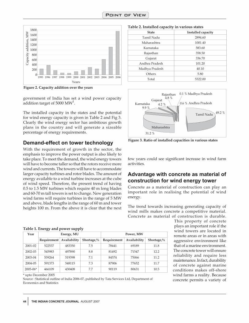
The installed capacity in the states and the potential for wind energy capacity is given in Table 2 and Fig 3. Clearly the wind energy sector has ambitious growth plans in the country and will generate a sizeable percentage of energy requirements.
demand-effect on tower technologyWith the requirement of growth in the sector, the emphasis to improve the power output is also likely to take place. To meet the demand, the wind energy towers will have to become taller so that the rotors receive more wind and currents. The towers will have to accommodate larger capacity turbines and rotor blades. The amount of energy available to a wind turbine increases at the cube of wind speed. Therefore, the present trend of having 0.5 to 1.5 MW turbines which require 40 m long blades and 60-70 m tall towers is set to change. New generation wind farms will require turbines in the range of 5 MW and above, blade lengths in the range of 60 m and tower heights 100 m. From the above it is clear that the next
few years could see significant increase in wind farm activities.
advantage with concrete as material of construction for wind energy towerConcrete as a material of construction can play an important role in realising the potential of wind energy.
The trend towards increasing generating capacity of wind mills makes concrete a competitive material. Concrete as material of construction is durable.
This property of concrete plays an important role if the wind towers are located in remote areas or in areas with aggressive environment like that of a marine environment. The concrete tower will ensure reliability and require less maintenance. In fact, durability of concrete against marine conditions makes off-shore wind farms a reality. Because concrete permits a variety of
Table 1. Energy and power supplyYear Energy, MU Power, MW
Requirement Availability Shortage,% Requirement Availability Shortage,%
2001-02 522537 483350 7.5 78441 69189 11.8
2002-03 545983 497890 8.8 81492 71547 12.2
2003-04 559264 519398 7.1 84574 75066 11.2
2004-05 591373 548115 7.3 87906 77652 11.7
2005-06* 466109 430408 7.7 90119 80631 10.5
* upto December 2005Source : Statistical outline of India 2006-07, published by Tata Services Ltd, Department of Economics and Statistics
Table 2. Installed capacity in various statesState Installed capacity
Tamil Nadu 2894.60Maharashtra 1001.40
Karnataka 583.60Rajasthan 358.50Gujarat 336.70
Andhra Pradesh 101.20Madhya Pradesh 40.10
Others 5.80Total 5322.00
45AUGUST 2007 The IndIan ConCreTe Journal
Point of View
mix designs, it can be made suitable for a wide range of site conditions for both foundation and pylon2. Through the use of admixture and special reinforcements, not just the strength of concrete can be improved but also its resistance to corrosion. Concrete can be tailor-made to meet specific requirements. Depending upon the site conditions both in-situ and pre-cast construction methods are suitable for wind tower construction.
Wind tower designA typical wind tower has two elements viz. foundation and the tower itself. Given below are basic pointers that help design the concrete towers for windmill installations
Foundation design for wind turbine towers3
Reinforced concrete spread footing is commonly used because it is simple and economic solution for the tower. This is useful for site conditions with good soil bearing capacity. However, if the soil is weak or the site has uncommon conditions such as constraint of space, or if the terrain is sloping or involves off shore construction, other types of foundation are used. These include pile foundations, drilled shafts, caissons, etc. In this section rectangular and hexagonal concrete spread footings are discussed.
The spread footing design aims at meeting stability and strength requirement against shear and flexural loads. Tie down rock anchors or micro-piles may be applied to reduce the size of the spread footing. The design basis requires details of soil bearing capacity, safety factor to be assumed and strength of concrete.
Af = L x Swhere, Af is the contact area of the soil with footing, L is the length of the footing and S is width of the footing.
I = SL3/12
where, I is moment of inertial of the area
Maximum soil stress is expressed by,
where, P is the tower axial load and e is the eccentricity of the load on the spread footing.
e = M/P
where, M is the ratio of the overturning moment
For service design with wind load, the soil bearing capacity should be higher than the maximum soil bearing stress.
The depth D of the spread footing is determined by the concrete shear strength of footing and the depth required for resisting the applied shear.
where, Vu = ultimate shear force, f = material reduction factor, f’c = design compressive strength of the concrete
The required reinforcement ratio rs of the spread footing can be determined by
where, fy = the yielding stress of the reinforcementMu = the ultimate moment
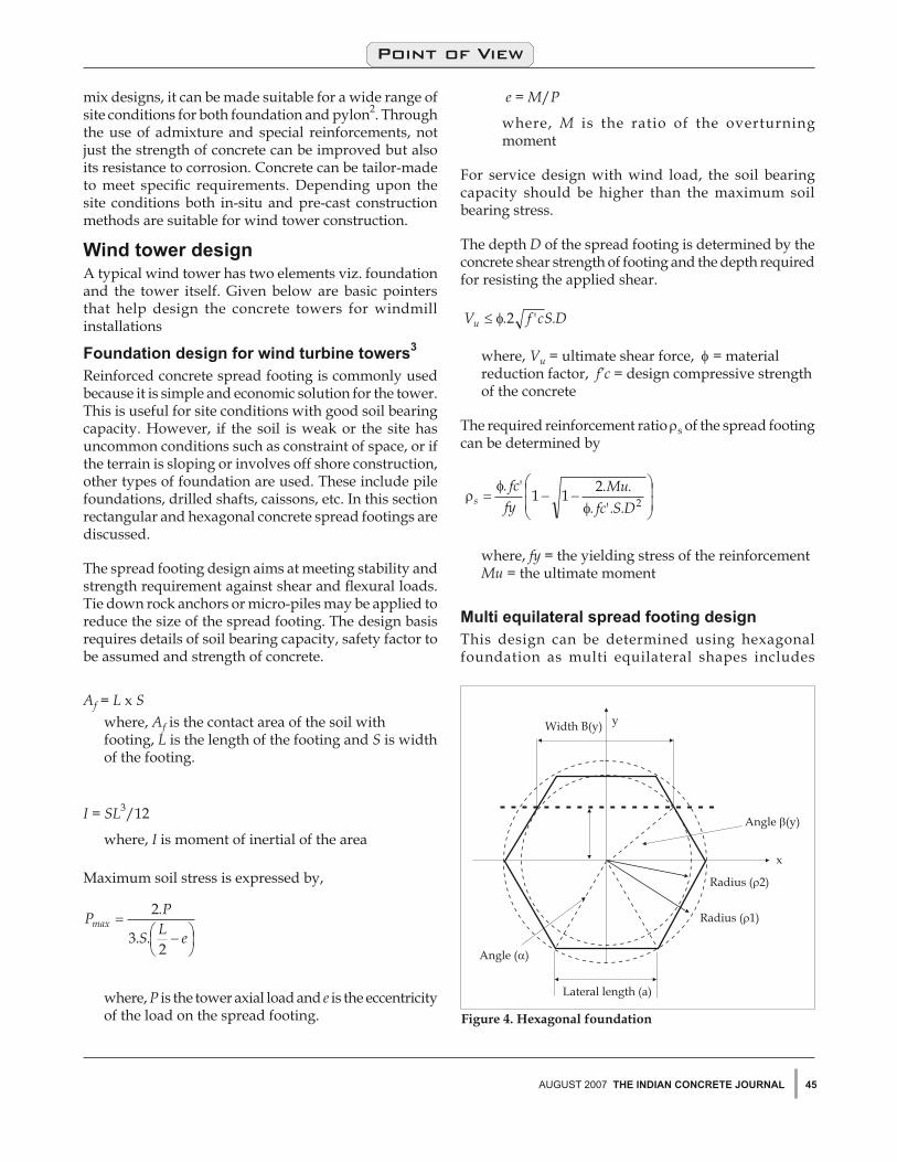
Multi equilateral spread footing designThis design can be determined using hexagonal foundation as multi equilateral shapes includes
The IndIan ConCreTe Journal AUGUST 200746
Point of View
hexagonal and octagonal, and easier to form than circular shape during construction.
The design requirement includes determination of area of the footing for hexagonal shape, calculation of outer and inner radius of the hexagon, calculation of the moment of inertia of the footing about x-x direction, evaluating maximum soil pressure by the applied axial load and bending moment.
The maximum soil stress with zero stress in the tension is one of the prerequisites for proceeding with the calculations. The results show that the square type of footing is less conservative than the hexagonal shape of footing for the same volume of concrete in the spread footing. Figure 4 gives a typical hexagonal footing design3.
Tower design based on concrete as the material of construction3
The windmill tower can be constructed following an approach similar to chimney construction.
design loadsWind loadsThe wind load applied on the turbine tower comprises of effects of direct wind pressure on the tower and the wind turbine loads. In designing the tower therefore calculations are made to reflect each characteristic load and suitable safety factor. Those loads that occur simultaneously are combined wherever necessary.
Wind turbine loadThe different loads that act as wind turbine loads both stationary and cyclic must be understood as aerodynamic loads from a uniform, steady wind speed and centrifugal forces generate a stationary load. A stationary but spatially uneven flow field over the swept areas causes cyclic load changes on the turning rotor.
Further, the mass forces that result from the rotating rotor blade weight cause periodic, non-stationary loads. In addition to the stationary and cyclic loads, the rotor is exposed to non-periodic and random loads caused by wind turbulence.
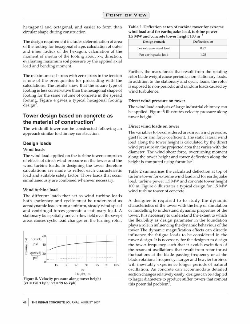
Direct wind pressure on towerThe wind load analysis of large industrial chimney can be applied. Figure 5 illustrates velocity pressure along tower height.
Direct wind loads on towerThe variables to be considered are direct wind pressure, gust factor and force coefficient. The static lateral wind load along the tower height is calculated by the direct wind pressure on the projected area that varies with the diameter. The wind shear force, overturning moment along the tower height and tower deflection along the height is computed using formulae3.
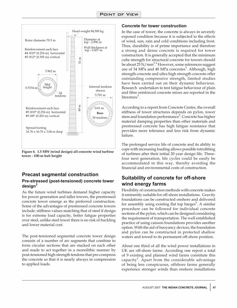
Table 2 summarises the calculated deflection at top of turbine tower for extreme wind load and for earthquake load, turbine power 1.5 MW and concrete tower height 100 m. Figure 6 illustrates a typical design for 1.5 MW wind turbine tower of concrete.
A designer is required to to study the dynamic characteristics of the tower with the help of simulation or modelling to understand dynamic properties of the tower. It is necessary to understand the extent to which the flexibility as design parameter in the foundation plays a role in influencing the dynamic behaviour of the tower The dynamic magnification effects can directly influence the fatigue loads to be considered in the tower design. It is necessary for the designer to design the tower frequency such that it avoids excitation of the resonant oscillations that result from rotor thrust fluctuations at the blade passing frequency or at the blade rotational frequency. Larger and heavier turbines will inevitably experience longer periods of natural oscillation. As concrete can accommodate detailed section changes relatively easily, designs can be adapted to larger diameters to produce stiffer towers that combat this potential problem2.
Table 2. Deflection at top of turbine tower for extreme wind load and for earthquake load, turbine power 1.5 MW and concrete tower height 100 m 3
Design remark Deflection, m
For extreme wind load 0.27
For earthquake load 1.25
47AUGUST 2007 The IndIan ConCreTe Journal
Point of View
Precast segmental constructionPre-stressed (post-tensioned) concrete tower design3 As the future wind turbines demand higher capacity for power generation and taller towers, the prestressed concrete tower emerge as the preferred construction. Some of the advantages of prestressed concrete towers include: stiffness values matching that of steel if design is for extreme load capacity, better fatigue properties over steel, unlike steel tower there is no risk of buckling and lower material cost.
The post-tensioned segmental concrete tower design consists of a number of arc segments that combine to form circular sections that are stacked on each other and made to act together in a monolithic manner by post-tensioned high strength tendons that pre-compress the concrete so that it is nearly always in compression to applied loads.
Concrete for tower constructionIn the case of tower, the concrete is always in severely exposed condition because it is subjected to the effects of wind, sun, rain and cold conditions including frost. Thus, durability is of prime importance and therefore a strong and dense concrete is required for tower construction. It is generally accepted that the minimum cube strength for structural concrete for towers should be about 25 N/mm2.4 However, some references suggest use of 34 MPa and 48 MPa concretes3. Although, high strength concrete and ultra high strength concrete offer outstanding compressive strength, limited studies have been carried out on their dynamic behaviour. Research undertaken to test fatigue behaviour of plain and fibre reinforced concrete mixes are reported in the literature5.
According to a report from Concrete Centre, the overall stiffness of tower structures depends on pylon, tower stem and foundation performance2. Concrete has higher material damping properties than other materials and prestressed concrete has high fatigue resistance that provides more tolerance and less risk from dynamic failure.
The prolonged service life of concrete and its ability to cope with increasing loading allows possible retrofitting of turbines after their initial 20 year design life. Three-four next generation, life cycles could be easily be accommodated in this way, thereby avoiding the financial and environmental costs of construction.
Suitability of concrete for off-shore wind energy farmsFlexibility of construction methods with concrete makes it eminently suitable for off-shore installations. Gravity foundations can be constructed onshore and delivered for assembly using existing flat top barges6. A similar procedure can be followed for individual concrete sections of the pylon, which can be designed considering the requirement of transportation. The well established practice of using caisson foundations provides another option. With the aid of buoyancy devices, the foundation and pylon can be constructed in protected shallow waters and towed to its permanent off-shore position.
About one third of all the wind power installations in UK are off-shore farms. According one report a total of 9 existing and planned wind farms constitute this capacity1. Apart from the considerable advantage of being less conspicuous, offshore farms generally experience stronger winds than onshore installations
The IndIan ConCreTe Journal AUGUST 200748
Point of View
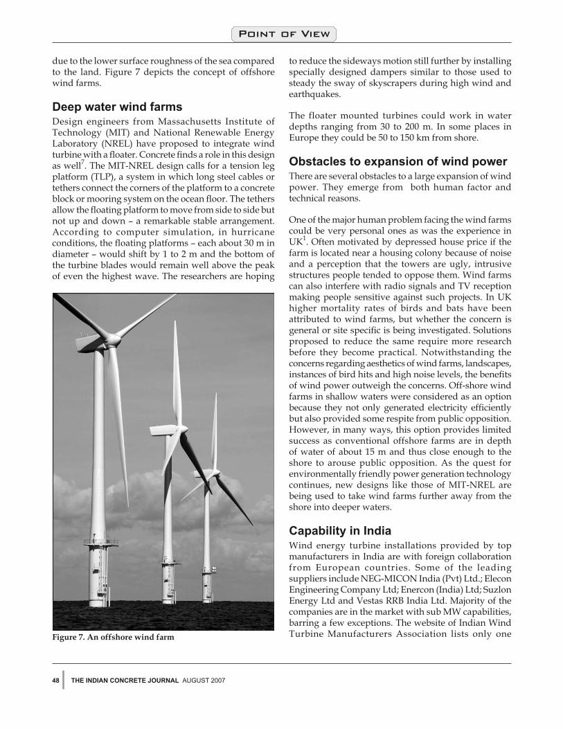
due to the lower surface roughness of the sea compared to the land. Figure 7 depicts the concept of offshore wind farms.
deep water wind farmsDesign engineers from Massachusetts Institute of Technology (MIT) and National Renewable Energy Laboratory (NREL) have proposed to integrate wind turbine with a floater. Concrete finds a role in this design as well7. The MIT-NREL design calls for a tension leg platform (TLP), a system in which long steel cables or tethers connect the corners of the platform to a concrete block or mooring system on the ocean floor. The tethers allow the floating platform to move from side to side but not up and down – a remarkable stable arrangement. According to computer simulation, in hurricane conditions, the floating platforms – each about 30 m in diameter – would shift by 1 to 2 m and the bottom of the turbine blades would remain well above the peak of even the highest wave. The researchers are hoping
to reduce the sideways motion still further by installing specially designed dampers similar to those used to steady the sway of skyscrapers during high wind and earthquakes.
The floater mounted turbines could work in water depths ranging from 30 to 200 m. In some places in Europe they could be 50 to 150 km from shore.
obstacles to expansion of wind powerThere are several obstacles to a large expansion of wind power. They emerge from both human factor and technical reasons.
One of the major human problem facing the wind farms could be very personal ones as was the experience in UK1. Often motivated by depressed house price if the farm is located near a housing colony because of noise and a perception that the towers are ugly, intrusive structures people tended to oppose them. Wind farms can also interfere with radio signals and TV reception making people sensitive against such projects. In UK higher mortality rates of birds and bats have been attributed to wind farms, but whether the concern is general or site specific is being investigated. Solutions proposed to reduce the same require more research before they become practical. Notwithstanding the concerns regarding aesthetics of wind farms, landscapes, instances of bird hits and high noise levels, the benefits of wind power outweigh the concerns. Off-shore wind farms in shallow waters were considered as an option because they not only generated electricity efficiently but also provided some respite from public opposition. However, in many ways, this option provides limited success as conventional offshore farms are in depth of water of about 15 m and thus close enough to the shore to arouse public opposition. As the quest for environmentally friendly power generation technology continues, new designs like those of MIT-NREL are being used to take wind farms further away from the shore into deeper waters.
Capability in IndiaWind energy turbine installations provided by top manufacturers in India are with foreign collaboration from European countries. Some of the leading suppliers include NEG-MICON India (Pvt) Ltd.; Elecon Engineering Company Ltd; Enercon (India) Ltd; Suzlon Energy Ltd and Vestas RRB India Ltd. Majority of the companies are in the market with sub MW capabilities, barring a few exceptions. The website of Indian Wind Turbine Manufacturers Association lists only one Figure 7. An offshore wind farm

49AUGUST 2007 The IndIan ConCreTe Journal
Point of View
company viz. Enercon (India) Ltd which offers tower construction with concrete9.
Almost all the top suppliers of windmill farms make their own towers in India. However, the most important capability, namely designing a tower for the wind turbine is still lacking in India.10 Both tubular towers and lattice towers are still designed in Europe and both the types are used in India. Although reputed agencies in India such as Structural Engineering and Research Centre (SERC) and Centre for Wind Energy Technology (C-WET) evaluate tower designs and participate in load measurement exercises for wind turbine towers, the required in-depth knowledge of loads on the towers in different operating conditions, tower dynamics, material specifications and the economics of design are areas that need to be strengthened along with increased knowledge of tower design software. There is a high level of dependence on the designer of the wind turbine while designing the tower and this is also a major hurdle to self reliance in tower design because not a single wind turbine manufacturer in India as of today designs wind turbines in India.
ConclusionIndia has considerable untapped wind energy potential. Future wind turbine design inevitably will have to be based on need for greater power generation. Concrete as a material of construction offers flexibility in design for wind tower construction including those for off-shore farms. The design professionals in the country need to develop design capability to meet the challenges of future energy requirement.
referencesFenwick, Sam, Wind power in the UK , International Cement Review, May 2007, pp. 109-110.)______Wind Power, Indian Infrastructure, May 2007, pp. 48-50Bromage Alan, Concrete for the next generation of wind farms, Concrete, January/February 2006, pp. 24-25.LWST Phase I Project Conceptual design Study : Evaluation of design and Construction Approaches for Economical Hybrid Steel/Concrete Wind Turbine Towers, M.W. LaNier, Berger/ABAM Engineers Inc. , Federal Way, Washington, National Renewable Energy Laboratory, Colorado, USA.______Reinforced Concrete Chimneys, Cement and Concrete Association, UK, 1975, pp. 84. Lohaus, L. and Anders, S., High cycle fatigue of ultra high performance concrete – Fatigue strength and damage development, FIB, Proceedings of the Second International Congress, June 5-8, 2006, Naples, Italy, Section 13, pp 1-10.______ Winds of change, Concrete, Cement and Concrete Association of New Zealand, September 2006, Vol. 50, No. 3.______http://www.whatsnextnetwork.com______http://www.indianwindpower.comPillai, G.M., Indigenisation and challenges in manufacturing, Wind power development in India.
1.
2.3.
4.
5.
6.
7.
8.9.10.