Concrete constituents, concrete technology and concrete ... · V Concrete constituents, concrete...
33
V Concrete constituents, concrete technology and concrete engineering 75 First concrete roundabout in Germany (Bad Sobernheim) Concrete constituents, concrete technology and concrete engineering V
Transcript of Concrete constituents, concrete technology and concrete ... · V Concrete constituents, concrete...

V Concrete constituents, concrete technology and concrete engineering
75
First concrete roundabout in Germany (Bad Sobernheim)
Concrete constituents, concrete technology and concrete engineering
V

VDZ Activity Report 2007 – 2009
76
Cements with several main constituents
Historically, raw materials that were avail-able in the various regions have been used to manufacture efficient cements that en-sure safe and reliable concrete structures. Consequently, there has been a long tradi-tion of using cements containing several main constituents. These days, because of increasing demands in terms of environ-mental protection, the manufacture and use of cements with several main constituents has taken on a new level of significance due to their ecological benefits.
With reference to conditions in Germany, the successful use in the building industry has proven the efficiency of CEM II and CEM III cements for challenging and du-rable concrete structures. The technical ap-plication properties of these cements, the ecological advantages of using them and examples of practical applications were described in a customer-oriented manner in the VDZ brochure “CEM II- und CEM III/A-Zemente im Betonbau – Nachhaltige Lösungen für das Bauen mit Beton”[CEM II- and CEM III/A cements in concrete con-structions – sustainable solutions for build-ing with concrete] from the German Ce-ment Works Association (can be purchased from www.beton.org).
Ecological advantagesThe positive ecological effect gained from the increasing use of cements with several main constituents can be seen in the changes in the building material profile for a met-ric ton of cement in Germany (Table V-1). In 2006, the contribution to the greenhouse effect and other environmental impacts was determined for an average German cement, consisting of the average proportions of ce-ment clinker and other main constituents. The environmental impacts of upstream supply chains, for example the electric- ity used to produce the material, were also considered. Compared to 1996, the contri-bution to the greenhouse effect had been re-duced by 23 % and consumption of non-re-newable energies had fallen by 38 %; con-tributions to other environmental impacts were also drastically reduced. These reduc-tions reflect the fact that in Germany more cement is produced with several main con-stituents and that the increased use of sec-ondary fuels has also had a positive effect on many key values.
Application regulations in GermanyThe current concrete standards DIN EN 206-1 and the German DIN 1045-2 con-
tain the application regulations for stand-ard cements in relation to exposure classes. When these standards were introduced, ap-plication restrictions applied to some stand-ard cements – based mainly on the lack of practical experience with these cements in Germany. In these cases, proof of suitabil-ity for use in specific exposure classes was provided by a general building authority approval (Technical Approval, TA) from the German Institute for Building Tech-nology (DIBt).
Currently, in Germany the following ce-ment types may be used in all exposure classes:
Portland cement CEM I Portland-blastfurnace cements CEM II/
A-S and CEM II/B-S Portland-burnt shale cements CEM II/
A-T and CEM II/B-T Portland-limestone cements CEM II/
A-LL Portland-fly ash cements CEM II/A-V
and CEM II/B-V Portland-composite cements CEM II/
A-M with other main constituents S, LL, T, D and V
Portland-composite cements CEM II/ B-M with national technical approval for application
Blastfurnace cements CEM III/A *)
*) Exposure class XF4: CEM III/A in strength class ≥ 42,5 N or strength class 32,5 R with up to 50 mass % blastfurnace slag
Since 2003, 18 general building authority approvals have been granted for CEM II/B-M (S-LL) and 4 approvals for CEM II/ B-M (V-LL) in Germany. Apart from the approvals for CEM II/B-M (V-LL), 16 ap-provals are currently valid for CEM II/ B-M (S-LL). In all the approvals, use is approved for concrete, reinforced con-crete and pre-stressed concrete according to DIN EN 206-1 in conjunction with DIN
1045-2 for exposure classes XC3, XC4, XD1 to XD3, XS1 to XS3, XF1 to XF4, XA1 to XA3, XM1 to XM3 as a sup- plement to the exposure classes X0, XC1 and XC2 already permitted in DIN 1045-2. In all approvals reference is made to use in mortar and concrete according to the old DIN 1045:1988 and the former pre-stressed concrete standard DIN 4227-1. Not permit-ted is use in grout for pre-stressing tendons according to DIN EN 447. In the meantime, uses for the manufacture of bore piles ac-cording to DIN EN 1536 in conjunction with DIN Technical Report 129 and for the manufacture of water-impermeable concrete according to the DAfStb Guide-line on concrete structures with water-en-dangering materials have been included in four approvals. From a technical point of view, the extension applies to all these approvals. However, the owner of the ap-proval must make a formal request to the DIBt. In addition to the above list of appli-cations, CEM II-M cements with general building authority approval may be used in all areas where the corresponding regula-tions refer to cement according to DIN EN 197-1, DIN 1164 or include cement gener-al building authority approval and with no specific usage restrictions. The following list contains several examples
DIN 1053-1 Masonry DIN 4158 Filler concrete joists for re-
inforced and pre-stressed concrete floors DIN EN 12843 Concrete masts and
poles DIN 4261-1 Small sewage treatment
plants DIN 18551 Sprayed concrete DIN 18148 (DIN 18162) Hollow light-
weight concrete blocks for walls (not reinforced)
DAfStb Guideline “Manufacture and use of dry concrete and dry mortar” (dry concrete guideline)
DAfStb Guideline “Manufacture and use of cement-based flowable concrete and flowable mortar”
1996 2006
Effect category
global Greenhouse effect (GWP) 872 670 kg CO2 equiv.
Ozone depletion (ODP) 1) 0 1.6 x 10⁻⁵ kg R11 equiv.
regional Acidification (AP) 1.68 0.92 kg SO2 equiv
Overfertilisation (NP) 0.20 0.12 kg PO43- equiv.
Summer smog (POCP) 2) 0.07 0.10 kg C2H4 equiv.
Primary energy (not renewable) 4 355 2 713 MJ
Table V-1: Building material profile for cement: potential effects and consumption of primary energy (from non-renewable energies) for the manufacture of 1 t of cement in Germany (aver-age)
1) Indicator was set to zero in 1996 2) In 1996 the indicator was based on a different calculation method

V Concrete constituents, concrete technology and concrete engineering
77
Fig. V-1: Aver-age standard compressive strengths of dif-ferent types of cement based on the results of third-party inspection
2 d70
60
50
40
30
20
10
0
28 d
CEM I32,5 R
Cem
ent s
treng
th in
N/m
m2
CEM II/A32,5 R
CEM II/B32,5 R
CEM II/B42,5 N
CEM III/A42,5 N
Fig. V-2: Rela-tive compres-sive strength of concretes with various CEM II and CEM III/A cements com-pared to CEM I concrete
CEM I 32,5 RCEM II/A-S 42,5 NCEM II/A-LL 32,5 RCEM II/B-S 42,5 NCEM II/B-T 42,5 NCEM II/B-M (S-LL) 32,5 RCEM II/B-M (V-LL) 32,5 RCEM III/A 42,5 NCEM III/A 32,5 N
w/c = 0.50 - 0.60c = 300 - 320 kg/m3
Age in days0 10 20 30
1.1
1.0
0.9
0.8
0.7
0.6
0.5
0.4
0.3
0.2
0.1
0.0
Relat
ive co
mpr
essiv
e stre
ngth
of c
oncr
ete
More information on uses of cement ac-cording to EN 197-1 can be found in Build-ing Rules List A, Part 1, Appendix 1.33 (2006/1). When engineering structures are built near highways in Germany (ZTV-ING) the customer must agree to the use of CEM II-M cements. Despite the restriction, numerous practical examples have also proven the suitability of CEM II/B-M ce-ments with technical approval in this area of application. In the long term it should be possible to remove this addendum.
A working group of CEN/TC 104/SC1 “Concrete” has developed a synopsis of the national application documents (NAD) for the European concrete standard EN 206-1. It describes some considerable dif-ferences in the use of cement. Apart from the traditional differences in market condi-tions and construction practice, it also re-flects the philosophies underlying the im-position of rules (see VDZ Activity Report 2005-2007). While the German applica-tion standard DIN 1045-2 lays down speci- fications for the application of all 27 basic cement types and for a number of CEM II-M cements, other NADs only regulate the application of a few cement types that have traditionally played a role in the respective national markets.
Cement propertiesThe properties of CEM II and CEM III/A cements have been continuously improved in the course of technical developments in the manufacturing process. They have also been adapted to suit current requirements, which has, in turn, considerably increased the bandwidth of potential applications. In particular, as regards early strength the manufacturers have adjusted the CEM II and CEM III/A cements so that they can be used in a similar way to the CEM I cements (Fig. V-1).
Properties of concrete in construction practiceIn addition to the environmentally compat-ible manufacture of CEM II and CEM III/A cements, because of their composition and especially considering the many different technological guidelines for concrete, they also have several advantages when used in fresh concrete and hardened concrete. For specific applications – including bridge and tunnel construction and road and building construction – it is possible to produce op-timally adjusted concretes. A number of im-portant properties are described below:
Strength developmentUnder practical building conditions, the strength development of concrete with
CEM II and CEM III/A cements is simi-lar to that of CEM I concretes. To satisfy practical requirements for early strength CEM II/B and CEM III/A cements are also available in strength class 42,5 N. Fig. V-2 shows the relative compressive strength development of concretes based on conventional CEM I, CEM II and CEM III/A cements with similar concrete com-positions and curing conditions. The rela-tive values result from the relation of the compressive strength of concrete after 2, 7 and 28 days to the 28-day compressive strength of the concrete. The test values for a CEM III/A 32,5 N are shown as a comparison. These results allow the in-vestigated concretes to be classified into medium and slow strength development classes. Accordingly, the concrete with the
CEM III/A 32,5 N cement can be classified as a slow strength developer. This classifi-cation is important to define the time need-ed for after-treatment.
DurabilityThe durability of the concrete is one of the key requirements for every structure. The most important feature is that the concrete element used must be resistant to loads and environmental impacts for its intended pe-riod of use, assuming it is maintained and repaired adequately.
CarbonationInvestigations of reinforced concrete and pre-stressed concrete structures that were constructed with concretes of different strength classes and with different com-

VDZ Activity Report 2007 – 2009
78
Fig. V-3: Influence of the cement type on the resistance to chloride penetration of concrete using the rapid test method
Age of concrete: 35 dc = 320 kg/m3
w/c = 0.50Storage in water
Increasing resistance to chloride penetration
Chlo
ride p
enet
ratio
n (m
igra
tion
coef
ficien
t) D CI
,M in
10-1
2 m2 /s
CEM I CEM II-LL CEM II-S CEM IIICEM II-M(V-LL)
CEM II-M(S-LL)
20
15
10
5
0
Fig. V-4: Freeze thaw resistance with de-icing salt of air-entrained concretes using the CDF method, cement content 320 to 365 kg/m3; w/c ratio 0.41 to 0.50; strength classes of the cements: 32,5 R and 42,5 N
Minimum Maximum
CDF assessment criterium for laboratory test samples ≤ 1 500 g/m2
CEM III/A CEM II-B-S CEM II/B-M(S-LL)
CEM II/B-M(V-LL)
CEM II/B-T CEM II/A-LL
1 800
1 600
1 400
1 200
1 000
800
600
400
200
0
Scali
ng in
g/m
2 (CDF
test)
positions have shown that with construc-tion components that were weathered out-doors, the type of cements used in Germany generally have no effect on the carbonation behaviour. Although higher carbonation depths may be found on dry, interior el-ements, because of the lower moisture con-tent of these elements there is no risk of the reinforcement corroding.
Chloride penetration resistanceDue to the finer pore system, in some cases the use of cements containing blastfurnace slag and fly ash can cause a marked increase in the concrete’s resistance to the penetra-tion of chlorides (Fig. V-3). With concretes intended for massive construction com-ponents according to the DAfStb Guide-line and when a CEM III/A or CEM III/B cement of exposure class XD3 or XS3 is used, the highest permissible water-cement ratio of 0.45 may be increased to 0.50 with
no change in the corrosion protection for the reinforcement.
Freeze-thaw resistance with or without de-icing saltWith the correct composition, process-ing and after-treatment according to DIN 1045, concretes with CEM II and CEM III/A cements have a high freeze-thaw resistance with or without de-icing salt. Consequently, they are very suita-ble for engineering structures and traf-fic areas. Only CEM III/A in strength class 32,5 N and CEM III/A 32,5 R with more than 50 mass % blastfurnace slag are excluded for exposure class XF4. Fig. V-4 shows some results from freeze-thaw-test with de-icing salt on concretes containing different cement types us-ing the CDF method. If freeze-thaw re-sistance with de-icing salt has to be test-ed, as a general rule the following cri-
terion is applied to evaluate the results: after 28 freeze-thaw cycles, scaling must not exceed 1 500 g/m² for a concrete that is meant to have adequate freeze-thaw resist-ance with de-icing salt. This corresponds to a scaling depth of around just 0.6 mm. This criterion may not be applied to sam-ples taken from structures.
Application examplesIn terms of the workability characteris-tics, strength development and durability of concrete, the CEM II and CEM III/A ce-ments that have been produced in Germa-ny to date have proven their reliability in practical applications over many decades. The current VDZ brochure “CEM II- und CEM III/A-Zemente im Betonbau – Nach-haltige Lösungen für das Bauen mit Beton” [CEM II- and CEM III/A cements in con-crete constructions – sustainable solutions for building with concrete] contains many practical examples from different areas of concrete construction.
OutlookAs an industry that uses a high volume of energy and raw materials, the cement in-dustry is very much affected by demands to conserve resources and reduce the use of energy and also by the global issue of climate control. Cement manufacturers are facing these challenges by continu-ously improving their production process-es in terms of energy and raw materials consumption.
If the industry wishes to continue along this path consistently, this raises the is-sue of producing cement types that have, in the past, only been produced and used in small quantities or which are not even included in the European cement stand-ard DIN EN 197-1, even if their composi-tions are not vastly different from the ce-ments covered by DIN EN 197-1. A cur-rent research project entitled “Ecological-ly and technically optimised cements with several main constituents” is involved in investigating these and similar cement compositions. This project is being car-ried out within the framework of the “kli-mazwei” research measure which is car-rying out research work into climate con-trol and controlling the effects of climate change (www.klimazwei.de) and is funded by the German Federal Ministry for Edu- cation and Research (BMBF).
The investigations are focussing on Port-land-limestone cements with 30 and 35 mass % limestone and cements with 10 to 25 mass % limestone in combination with blastfurnace slag and siliceous fly ash. The

V Concrete constituents, concrete technology and concrete engineering
79
Fig. V-5: Compressive strength of cements in relation to test age
80
70
60
50
40
30
20
10
0
Com
pres
sive s
treng
th in
MPa
0 20 40 60 80 100Test age in days
30 % LL10 % S 25 % LL20 % S 20 % LL40 % S 10 % LL10 % V 25 % LL20 % V 20 % LL
Fig. V-6: Compressive strength of concrete in relation to test age
80
70
60
50
40
30
20
10
0
Conc
rete
com
pres
sive s
treng
th in
MPa
0 20 40 60 80 100Test age in days
30 % LL10 % S 25 % LL20 % S 20 % LL40 % S 10 % LL10 % V 25 % LL20 % V 20 % LL
w/c = 0.50c = 320 kg/m³
Table V-2: Composition of the test cements with several main constituents
cements to be investigated were manufac-tured in the laboratory and also by large-scale cement works. During the manufac-turing process granulometric optimisation of the main constituents of the cement and optimisation of the sulphur agents were carried out with consideration of the ce-ments’ setting behaviour. Moreover, differ-ent types of main constituents were varied (for example, according to origin). The fo-cus of the investigations was placed on the durability of concretes manufactured using these cement types. The results of sever-al selected investigations that provide an overview of the cements and their com-positions are presented below Table V-2. The following results cannot be general-ized. They can, however, be used for fur-ther development work.
Compressive strength developmentThe development of compressive strength in several cements produced in the labora-
tory is shown in Fig. V-5. The results show that, in general, the strength of the cements produced in the laboratory for the durabil-ity investigations develops in the same way as in normal practice. To manufacture the concretes, aggregate (coarse Rhine sand from the research facility’s stocks) with a grain composition A16/B16 according to DIN 1045-2, Annex L was used. The com-positions of the concrete mixtures are based on the limit values for the composition and properties of concretes according to DIN Technical Report 100 “Concrete”.
Fig. V-6 presents examples of the develop-ment of compressive strength in concrete with a water-cement ratio w/c = 0.50 and a cement content c = 320 kg/m³ using se-lected cements produced in the laboratory. As expected, the early strengths of the con-cretes with CEM II cements were higher than concretes manufactured with cements not included in DIN EN 197-1. Apart from
two exceptions, the concretes at the age of 28 days had a similar strength level. Thus, it is generally possible to make a direct com-parison of the properties that are relevant for durability even after this time.
CarbonationFig. V-7 shows examples of the develop-ment of carbonation depths over time in several concretes that were investigated. The concretes were manufactured with a cement content of c = 260 kg/m³ and a wa-ter-cement ratio of w/c = 0.65. The carbon-ation depths of the concretes containing the laboratory cements investigated here were almost all below the values of the CEM III/A concrete given as a reference. CEM III/A can be used for all applications (exposure classes).
Chloride penetration resistanceThe concrete’s resistance to chloride pen-etration was determined with a rapid test
CementLimestone fineness approx.
7 000 cm²/g (Blaine)
Blastfurnace slag fineness approx.
4 000 cm²/g (Blaine)
Fly ash fineness ap-prox. 4 000 cm²/g
(Blaine)
Fineness of cement in cm²/g (Blaine)
Water demand in mass %
Origin of the constituents
30 % LL30 mass % limestone with
70 mass % CaCO3- - 6 265 31.5 Region 1
10 % S 25 % LL25 mass % limestone with
70 mass % CaCO3
10 mass % blast-furnace slag
- 6 195 30.5 Region 1
20 % S 20 % LL20 mass % limestone with
80 mass % CaCO3
20 mass % blast-furnace slag
- 5 150 30.5 Region 2
40 % S 10 % LL10 mass % limestone with
80 mass % CaCO3
40 mass % blast-furnace slag
- 4 970 30.0 Region 2
10 % V 25 % LL25 mass % limestone with
70 mass % CaCO3-
10 mass % siliceous fly ash
6 325 30.0 Region 1
20 % V 20 % LL20 mass % limestone with
70 mass % CaCO3-
20 mass % siliceous fly ash
5 955 29.0 Region 1

VDZ Activity Report 2007 – 2009
80
Fig. V-7: Carbonation depth of concrete in relation to test age
12
11
10
9
8
7
6
5
4
3
2
1
0
Carb
onat
ion
dept
h in
mm
0 100 200 300 400Test age in days
30 % LL10 % S 25 % LL20 % S 20 % LL40 % S 10 % LL10 % V 25 % LL20 % V 20 % LLCEM III/A Reference
w/c = 0.65c = 260 kg/m3
Fig. V-8: Chloride migration coefficients of the concretes in rela- tion to test age
30
25
20
15
10
5
0
D CI,M
in 10
-12 m
2 /s
30 % LL 10 % V25 % LL
20 % V20 % LL
10 % S25 % LL
20 % S20 % LL
40 % S10 % LL
35 d 98 d
w/c = 0.50c = 320 kg/m3
Fig. V-9: Scaling of concretes in the CF method in relation to the number of freeze-thaw cycles
2.00
1.75
1.50
1.25
1.00
0.75
0.50
0.25
0.00
Scali
ng in
kg/m
2
0 7 14 21 28 35 42 49 56 63Number of freeze-thaw cycles
30 % LL10 % S 25 % LL20 % S 20 % LL40 % S 10 % LL10 % V 25 % LL20 % V 20 % LL
w/c = 0.50c = 320 kg/m3
Fig. V-10: Relative dynamic elastic modulus of concretes in the CIF method in relation to the number of freeze-thaw cycles
120
100
80
60
40
20
0
Relat
ive d
ynam
ic ela
stic m
odul
us in
%
0 7 14 21 28 35 42 49 56 63Number of freeze-thaw cycles
30 % LL10 % S 25 % LL20 % S 20 % LL40 % S 10 % LL10 % V 25 % LL20 % V 20 % LL
w/c = 0.50c = 320 kg/m3
method (migration test). The test samples were cured in water for 35 and 98 days respectively. Concretes in exposure class XD2/XS2 were manufactured with a wa-ter-cement ratio of w/c = 0.50 and a ce-ment content of c = 320 kg/m3. The chlo-ride migration coefficients DCl,M (Fig. V-8) that were determined when laboratory ce-ments containing 30 mass % limestone was used were approximately 28 · 10-12 m2/s after 35 days and approx. 18 · 10-12 m2/s after 98 days, and are thus in the same range as concretes made with Portland ce-ment. The concretes that were manufac-tured with cements containing fly ash or blastfurnace slag exhibited a lower chloride migration coefficient DCl,M, which was in the range of approx. 4 to 24 · 10-12 m2/s af-ter 35 days and approx. 3 to 10 · 10-12 m2/s after 98 days.
Freeze-thaw resistance with or without de-icing salt Results of the frost resistance tests accord-ing to the CF/CIF method and results of the tests into frost de-icing salt resistance ac-cording to the CDF method are presented and evaluated below. In Germany, asses-ment criterions for scaling (CF/CDF meth-od) and assesment criterions for internal structural damage (CIF method) are defined by the German Federal Waterways Engi-neering and Research Institute (BAW) in the “Frost test of concrete” fact sheet.
In the investigations that were conducted with the CF method, the concretes (cement content c = 320 kg/m³, water-cement ratio w/c = 0.50) exhibited scaling well below the assessment criterion of 1.0 kg/m² after 28 frost-thawing sequences that is defined
in the “Freeze-thaw test of concrete” fact sheet issued by the German Federal Wa-terways Engineering and Research Insti-tute (BAW) (Fig. V-9). The BAW assess-ment criterion for the CIF method is a rel-ative dynamic elastic modulus of 75 % after 28 freeze-thaw cycles. As Fig. V-10 shows, the concretes containing cements with 30 mass % limestone and 10 mass % blastfurnace slag and 25 mass % limestone exhibited a relative dynamic elastic modu-lus of more than 80 % after 28 freeze-thaw cycles. When cements with a composition outside the standard were used, the crite-rion was not fulfilled within the scope of the investigations conducted by the Re-search Institute.
The CDF test is used to test resistance to freeze-thaw attack with simultaneous de-

V Concrete constituents, concrete technology and concrete engineering
81
Fig. V-11: Scaling of air-entrained concretes in the CDF method in relation to the number of freeze-thaw cycles
2.00
1.75
1.50
1.25
1.00
0.75
0.50
0.25
0.00
Scali
ng in
kg/m
2
0 7 14 21 28Number of freeze-thaw cycles
w/c = 0.50c = 320 kg/m3
Air content approx. 5.0 Vol. %
30 % LL10 % S 25 % LL20 % S 20 % LL40 % S 10 % LL10 % V 25 % LL20 % V 20 % LL
Fig. V-12: Chlo-ride migration coefficients of concretes con-taining labora-tory and works cements in rela-tion to test age
30
25
20
15
10
5
0
D CI,M
in 10
-12 m
2 /s
30 % LL Laboratory
30 % LL Works
20 % V 20 % LLLaboratory
20 % V 20 % LLWorks
35 d 98 d
w/c = 0.50c = 320 kg/m3
Fig. V-13: Rela-tive dynamic elastic modulus of concretes containing laboratory and works ce-ments in the CIF method in relation to the number of freeze-thaw cycles
120
100
80
60
40
20
0
Relal
tive d
ynam
ic ela
stic m
odul
us in
%
0 7 14 21 28 35 42 49 56 63Number of freeze-thaw cycles
w/c = 0.50c = 320 kg/m3
30 % LL Works30 % LL Laboratory20 % V 20 % LL Works20 % V 20 % LL Laboratory
icing agent stress. Generally, a defined de-icing salt solution is used (3 % NaCl solu-tion). In the test for freeze-thaw resistance with de-icing salt (CDF) of air-entrained concrete surface scaling is dominant and has priority for the assessment. The CDF-method was tested on concretes with a ce-ment content of c = 320 kg/m³ and a wa-ter-cement ratio of w/c = 0.50. The results are shown in Fig. V-11. Concrete scal-ing was between 0.35 and 1.25 kg/m² af-ter 28 freeze-thaw cycles and was thus be-low the assessment criterion of 1.5 kg/m² after 28 freeze-thaw cycles which applies to this method.
Figures V-12 and V-13 show compara-tive results of further investigations of concretes manufactured using cements produced in the laboratory and in cement works. A requirement for the large-scale manufacture of cements in the works was that the manufacturing process had to be adapted to suit constituents that were avail-able locally. As the figures show, the du- rability of concretes containing cements with 30 mass % limestone and 20 mass % fly ash in combination with 20 mass % lime-stone was improved in some cases. Field site tests using the works cements under XF3 conditions will show how the con-cretes behave in practice.
Cement and admixtures
The use of concrete admixtures to control the properties of the fresh and hardened concrete is state of the art in concrete pro-duction today. Some 90 % of the concrete produced in Germany contains concrete admixtures. In 2007, consumption of ad-mixtures in Germany was about 12 kg per metric tonne of cement. Overall, more than 550 concrete admixtures which can be clas-sified in 15 different functional groups are presently available in Germany. At approx. 75 %, concrete plasticisers and super-plas-ticisers account for the lion’s share.
There is still a substantial lack of scientifi-cally backed understanding of the precise working mechanisms of some concrete ad-mixtures. The influence that concrete ad-mixtures have on the hydration of cement and thus on the properties of fresh and/or hardened concrete is usually determined empirically and is the subject of some con-troversial discussion. This applies espe-cially to super-plasticisers based on poly-carboxylate ether, shrinkage reducing ad-mixtures and new air-entraining concrete admixtures. These have been extensively investigated by the Research Institute.
Super-plasticisersSynthetic organic polymers with carboxy-lic groups, such as polycarboxylate ethers (PCE), constitute an advance in the field of active ingredients contained in super-plasti-cisers. Some 45 % of the super-plasticisers
used today are based on PCE, and the ten-dency is rising. PCEs consist of main chain molecules, such as polyacrylic acid, and side chain molecules, such as polyethylene oxide, which are fixed to the main chain. Via their negatively charged main chain,

VDZ Activity Report 2007 – 2009
82 Fig. V-14: Zeta potential of pastes from Portland-composite and blastfurnace cements manufactured in the laboratory with the same clinker components
Cement paste with w/c = 0.5
-20
-15
-10
-5
0
0 20 40 60 80 100
S or LL in mass %
Zeta
pot
entia
l in m
V
LL1 LL2S1 S2
BET- Content of Methylene Surface CaCO3 blue value in cm2/g in % in g/100 g LL1 11 881 99.1 0.03 LL2 73 812 83.5 0.33 S1 15 463 – – S2 11 593 – –
Fig.V-15: Zeta potential of pastes from Portland-composite and blastfurnace cements manufactured in the laboratory with the same clinker components in relation to the amount of PCE super-plasti-ciser that was added
Zeta
pot
entia
l in m
V
Cement paste w/c = 0.5
-20
-15
-10
-5
0
0.00 0.10 0.20 0.30 0.40 0.50
Super-plasticiser in mass % of cement
without S/LL35 mass % LL135 mass % LL235 mass % S165 mass % S1
the PCEs adsorb on the positively charged surfaces of the cement, its hydration prod-ucts and other fine solids particles. The dis-persing effect is largely attributable to the steric repulsion of the side chains. Vari- ation of the charge and the length ratio of the main chain and the side chains allows adjustment of different properties, such as a strong initial plasticising effect and/or ex-tended workability of fresh concrete.
In addition to parameters such as the exact point when the material is added, the mix-ing time and the temperature of the fresh concrete, the effects of the super-plasti- cisers are also affected by the cement that is used. Practical experience has shown that even if the same type and quantity of super-plasticiser and the same type of cement are used, in unfavourable cases effects such as rapid loss of consistency, segregation, in-tensive bleeding and delayed strength de-velopment may occur. While knowledge of the effects that traditional super-plasti- cisers have on Portland cement exists, there is still need for more research into the inter- actions between Portland-composite/blast-furnace cements and super-plasticisers based on polycarboxylate ether.
The Research Institute is investigating the effects of the main constituents of cement (clinker, blastfurnace slag and limestone) on super-plasticiser adsorption. In combi-nation with rheological measurements it is being determined whether conclusions can be drawn as regards initial plasticising and
the duration of plasticising of super-plasti-cisers on the basis of the zeta potential. The aim is to determine substance parameters that must be known to understand the me-thodical interaction between cement and su-per-plasticisers e.g. in order to prevent dis-colouration of fair-faced concrete surfaces as a result of sedimentation.
Zeta potential investigationsThe zeta potential is an electro-kinetic po-tential in the interface between the mo-bile and the rigid part of the double lay-er formed at the transition zone between solids and aqueous solutions. The poten-tial indicates the charge conditions on the particle surface. Changing this poten-tial by adding super-plasticisers allows to investigate the adsorption of the su-per-plasticiser molecules on the surfaces of various main constituents of cement. In the Research Institute the zeta po-tential can be determined on suspen-sions rich in solids with normal w/c ratios using an electro-acoustic meas- uring method.
Fig. V-14 shows the effect that various pro-portions of blastfurnace slag (S1, S2) and limestone (LL1, LL2) have on the zeta po-tential of laboratory cement pastes contain-ing the same Portland cement clinker com-ponents. The zeta potential of the cement paste with no main constituents other than clinker was approx. -17 mV.
The zeta potential of the cement pastes containing blastfurnace slag shifted in the same manner from the negative range to-wards the isoelectric point (0 mV) as the content of S1 and S2 was increased. The reduction in zeta potential did not corre-late with the increase in blastfurnace slag. In water the blastfurnace slags exhibited a zeta potential of approx. -15 mV. LL1 re-duced the negative zeta potential of the pastes. This course is generally expected in limestone with a very high CaCO3 con-tent, which usually exhibits a positive zeta potential in water. On the other hand, LL2 caused an increase in the negative zeta po-tential of the pastes. Based on initial find-ings, this can be attributed to the clay con-stituents in LL2.
The results show that blastfurnace slag and limestone can have a considerable influ-ence on the zeta potential of cement pastes. Consequently, the sorption of super-plasti-ciser molecules can also be affected.
Fig. V-15 presents the course of the ze-ta potential in pastes of selected labora-tory cements containing blastfurnace slag and limestone respectively with increasing quantities of super-plasticiser (PCE). As the quantity of anionic PCE increased, the negative zeta potential of the cement paste with no other main constituents shifted to-wards the isoelectric point. This contradic-tory behaviour is attributed to a shift in the measuring level of the zeta potential caused by the adsorbed PCE molecules.

V Concrete constituents, concrete technology and concrete engineering
83
Fig. V-16: Total shrinkage (top) and shrinkage reduction (bot-tom) of concrete with Portland cement and w/c = 0.50 after dry curing in a 20/65 climate; SRA amount: 4.5 mass % of water
Concrete with CEM Iw/c = 0.50Storage 1 d formworkafter this 20/65
1 10Age in d
Shrin
kage
redu
ction
in %
Tota
l shr
inka
ge in
mm
/m
0.6
0.4
0.2
0.0100
80
60
40
20
0100 1,000
ReferenceSRA1SRA2
Fig. V-17: Total shrinkage (top) and shrinkage reduction (bot-tom) of concrete with Portland cement and w/c = 0.50 after cur-ing for six days under water and then in a 20/65 climate; SRA amount: 4.5 mass % of water
Concrete with CEM Iw/c = 0.50Storage1 d formwork,6 d under waterafter this 20/65
Shrin
kage
redu
ction
in %
Tota
l shr
inka
ge in
mm
/m
0.6
0.5
0.4
0.3
0.2
0.1
0.0
-0.1100
80
60
40
20
0
-201 10
Age in d100 1,000
ReferenceSRA1SRA2
The zeta potential of the cement paste with 35 mass % S1 and 35 mass % LL1 was al-ready reduced considerably in the same way as the cement with no other main con-stituents with small quantities of super-plasticiser. The zeta potential of the ce-ment paste with 65 mass % S1 was affected slightly by the addition of super-plasticiser. It is likely that the molecules adsorb main-ly on the clinker components and not on the blastfurnace slag S1 or limestone LL1.
The zeta potential of the paste with 35 mass % LL2 changed only slightly when about 0.3 mass % super-plasticiser was added. This is attributed to the large surface area of the clay constituents on to which a cer-tain proportion of the super-plasticiser mol-ecules adsorb non-specifically. When more super-plasticiser was added, this produced a marked shift of the zeta potential in the direction of the isoelectric point.
Shrinkage reducing admixtures Shrinkage is caused by changes in the moisture content in concrete which result in changes in the inner forces in the struc-ture of the hardened cement paste matrix due to environmental effects or drying in the concrete. This creates tensile stress that causes the hardened cement paste matrix to contract. Shrinkage of concrete leads to deformations that may cause stress in struc-tural elements in case of constraint. As a consequence, cracks can occur that have a negative effect on the durability of the con-crete. The Research Institute of the Cement Industry is currently investigating whether potentially negative effects can be signifi-cantly reduced through the use of shrink-age reducing admixtures.
To reduce shrinkage of concrete, shrinkage reducing admixtures (SRA) were devel-oped in Japan at the start of the 1980s and have also been used in Europe since about 1997. In Germany, SRAs have been used only in the manufacture of screeds and ce-ment-based mixtures. Since at present no general building inspectorate approvals have been issued for this type of admix-ture, SRAs may not be used in load-bear-ing structural elements made from con-crete, reinforced concrete or pre-stressed concrete.
The Research Institute of the Cement In-dustry conducted investigations into the working mechanisms of shrinkage reduc-ing admixtures as part of an AiF-sponsored research project. The results show that the shrinkage reducing effect does not corre-late with the reduction in surface tension as assumed in a number of other inves-
tigations. Active substances in the SRAs may increase the so-called disjoining pres-sure effect of the pore solution, the reduc-tion of which is essentially responsible for shrinkage of cement paste. Increased rel-ative moisture in hardened cement paste may intensify the disjoining pressure ef-fect of the pore solution. However, some active substances exhibit no shrinkage re-ducing effect. In fact, they increase shrink-age of hardened cement paste under sealed conditions and also when the paste is dried at 20 °C and 65 % relative humidity (dry curing). One of the reasons for this could be the considerable increase in the gel pore content compared to hardened ce-ment pastes with no SRA. On the basis
of these findings, the Research Institute is currently conducting a subsequent research project funded by AiF. In this project the effect of SRA on shrinkage, the mechani- cal properties and the durability of concrete are being investigated.
Effect of SRA on concrete shrinkageThe first results show that the properties of fresh concrete are not significantly affect-ed by SRA, regardless of the water/cement ratio or the cement paste content.
Total shrinkage of concrete containing Portland cement can be reduced by up to about 40 % by SRA depending on the ce-ment paste content and the form of cur-

VDZ Activity Report 2007 – 2009
84
ing. Fig. V-16 shows an example of total shrinkage (top) and shrinkage reduction (bottom) when the concrete was cured at 20 °C and 65 % relative humidity (20/65). The reduction in shrinkage is the shrink-age of concretes containing SRA in rela-tion to the reference sample without SRA. During curing (L1), the test samples dry directly after demoulding within 24 hours. After one year, total shrinkage was reduced by shrinkage reducing admixture SRA1 and SRA2 respectively by about 20 % and 40 % respectively (see Fig. V-16, bot-tom). Fig. V-17 presents total shrinkage (top) and the corresponding shrinkage re-duction (bottom) of concrete containing Portland cement after being cured for six days under water, followed by curing in a 20/65 climate (L2). In the top picture it can be seen that the subsequent curing of the concretes in water had only a minor effect on the extent of reduction after one year. When the sample was cured in wa-ter for seven days, the respective reduction in shrinkage (see Fig. V-17, bottom) was slightly less than with dry curing after one year and was approx. 10 % with SRA1 and approx. 30 % with SRA2. In the research project it is currently being investigated whether this behaviour also occurs in con-cretes containing different cements and dif-ferent water/cement ratios. The results of investigations into the effect of SRA on the shrinkage of concrete with varying cement paste contents show that the increased ex-tent of shrinkage associated with increas-ing cement paste content can be reduced with SRA. Hence, easily workable con-cretes rich in cement paste can be manu-factured with low shrinkage.
Effect of SRA on the mechanical pro-perties of concretesMany publications state that the compres-sive strength of concretes can be reduced through SRA. The effect of SRA on the compressive strength of concrete was been investigated so far on Portland cement con-cretes with a water/cement ratio of w/c = 0.50. The concretes were cured in climates (L1), (L2) and sealed (L3). The concretes with SRA1 and SRA2 exhibited roughly 20 % (SRA2) less compressive strength than the respective reference concrete with-out SRA – largely regardless of age and curing method. The concrete with shrink-age reducing admixture SRA1 exhibited a higher compressive strength than the con-crete with shrinkage reducing admixture SRA2 at all ages and with all three meth-ods of curing.
The static modulus of elasticity of concrete with Portland cement and a water/cement
ratio of w/c = 0.50 was reduced by up to 7 % with shrinkage reducing admixtures SRA1 and SRA2 with curing method L2 and after 91 days. With curing method L1 after 2 days the flexural tensile strength was about 12 % (SRA2) and approx. 20 % (SRA1) higher than in the concrete with-out SRA. In contrast, after 2 days curing in water the flexural tensile strength of the concretes with SRA was about 15 % lower than the reference sample with no SRA. Af-ter 91 days the effect of the SRA on flexural tensile strength was insignificant.
The results of the investigations into the effect of SRA on the mechanical proper-ties of concrete largely confirm the results already determined for cement paste (see VDZ Activity Report 2005-2007).
Air-entraining admixtures In unset concrete air-entraining admixtures are added to create a lot of small, evenly distributed air voids with a diameter ≤ 300 µm. In hardened concrete these voids serve as an expansion space to relieve the pres-sure created when the pore solution freezes. The air voids also interrupt the capillary pore system and reduce water absorption in the concrete. Both mechanisms of action contribute to the adequacy of the concrete’s resistance to freeze-thaw with de-icing salt. Road paving concrete which is covered with de-icing salt in winter must be man-ufactured as air-entrained concrete. Other areas of application are bridge caps, scrap-er tracks and concretes used in hydraulic engineering (exposure class XF3).
Manufacturing of proper air-entrained con-crete requires a suitability test in which the main effects that the composition of the concrete, the temperature of the unset con-crete and the mixing time have on the for-mation of air voids are determined. Suit-able regulations for the composition and manufacture of air-entrained concrete are defined and have proven their worth in the past. Traditional super-plasticisers based on melamine, naphthalene and lignin sul-phonate have long been used to regulate consistency for the manufacture of air-en-trained concrete.
When super-plasticisers based on poly-carboxylate ether (PCE) are used, it has been determined that the requirements for the formation of the air void system are not always fulfilled. Accordingly, in some cases the air void structure is not stable, which means that the total air content and the air void distribution can change. In a few cases, despite compliance with the to-tal air content in the fresh concrete, the
requirements for the air void parameters measured on hardened concrete (spacing factor and micro air void content) are not achieved. In cases such as this, the accu-rate adjustment of the micro air void con-tent, which prevents frost and de-icing salt damage, is no longer guaranteed. To clarify the facts, in 2006 the German Committee for Structural Concrete (DAfStb) formed a working group headed by the Research Institute. Extensive research work was also commenced.
Research at the Institute Insufficient information is available about the precise interactions between air-en-training admixtures and super plasti- cisers, especially PCE. Because of this, dur- ing the period under review the Research Institute started work on an AiF-funded re-search project. The investigations will pro-vide fundamental knowledge about the ef-fects and interactions between the air-en-training admixtures and super plasticisers in combination with cement. The aim is to manufacture appropriate air-entrained concrete containing super plasticisers by identifying “robust” admixture combina-tions that enable the specific formation of air voids.
The formation of air voids is being inves-tigated in cement pastes, mortar and con-crete with different combinations of air-entraining admixtures, super plasticisers and cement. In cement paste and mortar, the formation of air voids and foam is be-ing analysed in relation to the admixture- cement combination. Sorption of the super plasticiser on cement particles is de-termined with paste and flotation exper-iments. In addition, the formation of air voids on unset and hardened concrete will be determined using selected admixture- cement combinations. In the course of these experiments, the air entraining parameters will be determined for hardened concrete and the concretes’ de-icing resistance will be analysed using the CDF method. The re-search project is being carried out in close collaboration with the Institute of Build-ing Materials Research (IBAC) at Aachen University in Germany. One of the focus-es here is research into the interactions be-tween air-entraining admixtures and super plasticisers when fly ash is used.
Formation of foam Initial research has been carried out on the foam formation capacity of air-entraining admixture/super plasticiser combinations in cement suspensions. The maximum per-missible amount of super plasticiser was added (3 mass % of cement). In a stand-

V Concrete constituents, concrete technology and concrete engineering
85Fig. V-18: Formation of foam in a cement suspension in relation to the type and amount of air-entraining admixture (AEA) added and the time when the super plasticiser (SP) is added.
0
2
4
6
8
10
12
14
16
0.00 0.05 0.10 0.15 0.20 0.25 0.30 0.35 0.40
Amount of active agent of air-entraining admixture in mass % of cement
Foam
, heig
ht in
cm
Only AEA (Natural active agent)
Synthetic surfactant
Modified wood resin
Only AEAFirst AEA
First SP
Addition of SP (approx. 8 cm)
Only AEA (Synthetic active agent)
First AEA(Natural active agent) then SP
First AEA (Synthetic active agent) then SP
First SP (Natural active agent) then AEA
First SP (Synthetic active agent) then AEA
ardised experiment water, cement and ad-mixture were mixed in a plain cylinder, fine air bubbles were introduced to the suspen-sion and the height of the foam that formed was measured. Fig. V-18 shows the forma-tion of foam in relation to the amount of active agent in the air-entraining admix-ture and super plasticiser (PCE for ready-mixed concrete) that was added. The ex-periment was stopped when the foam over-flowed from the cylinder (height of foam > 16 cm). This status is shown by the arrow in Figure V-18. First, in a “reference ex-periment” the formation of foam of a syn-thetic air-entraining admixture (syn. sur-factant) and a natural air-entraining admix-ture (modified wood resin) with no added super plasticiser (only air-entraining ad-mixture) were determined. Subsequently, the effect of the time when the super plas-ticiser was added was also investigated. In one case the super plasticiser was added before the air-entraining admixture (first SP) and in the second case the air-entrain-ing admixture was added (height of foam approx. 8 cm) before the super plasticiser (first AEA). In the second option the aim was also to investigate whether the forma-tion of foam was affected by the subsequent addition of super plasticiser.
With the same concentration of active agents, the synthetic air-entraining admix-ture exhibited a much stronger foam for-mation than the air-entraining admixture based on a natural active agent. Apart from this, the sequence in which the admixtures were added also had a major effect on the formation of foam. If about 8 cm of foam was produced by adding the air-entraining admixture first before the super plasticiser was added, there was less overall formation of foam. The formation of foam was hardly affected at all by the subsequent addition of the super plasticiser and the foam height of approximately 8 cm fell only slightly. If the super plasticiser was added before the air-entraining admixture, much more foam formed. A possible reason for this is the reduced sorption of the air-entraining admixture molecules on the cement parti-cles when the sorption places are already filled by the super plasticiser molecules. The air-entraining admixture molecules can stabilise more air bubbles and more foam forms. It is possible that in practice the effects that occur during the formation of air voids in concrete can be attributed to these differences in the sequence in which the admixtures are added. Generally, when concrete is being manufactured the air-entraining admixture is added before the super plasticiser.
Alkali-silica reaction
In an alkali-silica reaction (ASR), all con-stituents in the aggregate containing sili-ca that is sensitive to alkalis react with the alkalis of the pore solution in the cement paste. The reaction product is an alkali sili-ca gel that endeavours to absorb water. The associated increase in volume is described as concrete expansion and can cause cracks in the concrete. In many concretes an ASR takes place with no damage. The triggers for and the course of a damaging ASR in concrete depend on the type, reactivity, quantity and particle size distribution of the alkali-reactive aggregate, the effective alkali content in the pore solution and on sufficient moisture being present. If one of the three requirements is missing, no dam-aging ASR occurs. If the conditions for a damaging ASR exist, visible cracks can ap-pear in the concrete. However, it is not al-ways possible to distinguish these cracks from other cracks that are the result of oth-er damage, such as frost attack. If a damag-ing ASR is suspected, it is imperative that an expert carries out a thorough examina-tion to clarify whether a damaging ASR has taken place.
Regulations In Germany, the German Committee for Structural Concrete (DAfStb) issues guide-lines – “Preventive measures against a damaging alkali reaction in concrete” – to prevent ASR damage, these guidelines
are generally known simply as the Alka-li Guidelines. The latest version of the Al-kali Guidelines was published in Febru-ary 2007. The guidelines are introduced by the building authorities with publication in Version 2008/1 of Construction Products List A, Part 1.
The Alkali Guidelines are split into three parts:Part 1: GeneralPart 2: Aggregates containing opaline sand-stone and flintPart 3: Crushed alkali-reactive aggregates
Effects on building with concreteThe guidelines offer practical solutions for building with concrete which, how- ever, must be applied. In this connection, it must be mentioned that there is also the option of classifying an aggregate as non-reactive (E I) on the basis of a petrograph-ic description with no other test being re-quired. This applies to aggregates that are not listed in the guidelines or which are not excavated in regions listed in the guide-lines. A requirement is that no damag-ing ASR has occurred with the aggregate when used under normal building condi-tions (Fig. V-19).
With the concrete formulations and ce-ment contents generally used these days, there are also many uses in civil engineer-ing and engineering structures (moisture classes WO, WF, and WA, Table V-3) for

VDZ Activity Report 2007 – 2009
86
Fig. V-19: Re-quirements for classifying an aggregate as non-reactive (E I) on the ba-sis of a petro-graphic descrip-tion with no other tests
Fig. V-20: ASR effects on build-ing with con-crete when using aggregates from a region ac-cording to Part 2 of the Alkali Guidelines (c = cement content, NA = NA ce-ment according to DIN 1164-10)
Fig. V-21: ASR effects on build-ing with con-crete when using aggregates ac-cording to Part 3 of the Alkali Guidelines (c = cement content, NA = NA ce-ment according to DIN 1164-10)
Aggregate is■ not from a region according to Part 2 of the Alkali Guidelines■ not crushed aggregate according to Part 3 and is not gravel with more than 10% crushed aggregate according to Part 3
No damage caused by ASR in real concrete structures – petrographic description
E I (non-reactive)
No restrictionsCement/cement content
aggregate
WO, WF, WA, WS 1)
1) Use of road paving cements Follow the regulations of TL Beton-StB 07 and ARS
Aggregate is
■ from a region according to Part 2 of the Alkali Guidelines
Test according to the Alkali Guidelines: test method according to Part 2 of the Guidelines
E I-O/OF (non-reactive)
E II-O
EI III-O/OF 2)
(reactive)
No restrictions
Cements / cement contentsaggregates
WOWFWA
WS 1)
E II-OF
E II-O/OF (medium reactive)
E III-O E III-OF
No restrictionsCements / aggregates
No restrictionsCements / aggregates
c ≤ 330 kg/m3
WO, WF(WA with NA)
c ≤ 330 kg/m3
WO, WF(WA with NA)
c ≤ 330 kg/m3
WO(WF, WA w. NA)
WO(WF with NA)
1) Use of road paving cements Follow the regulations of TL Beton-StB 07 and ARS
2) Applies also to aggregates that have not been assessed
Aggregate is
■ crushed aggregate according to Part 3 or is gravel with more than 10% crushed aggregate according to Part 3
Test according to Alkali Guidelinesaccelerated mortar bar test/concrete prism test
E I-S (non-reactive) E III-S 2) (reactive)
No restrictions
Cements / cement contentsaggregates
WO, WF, WA, WS 1)
No restrictionsCements / aggregates
c ≤ 300 kg/m3: WO, WF, WA, WS 1)
300 < c ≤ 350 kg/m3: WO, WF (WA with NA)c > 350 kg/m3: WO (WF with NA)
aggregates that are classified as E II (medi-um reactive) or E III (reactive). Figures V-20 and V-21 illustrate the fact that in many cases even for aggregates classified as E II or E III according to Parts 2 and 3 of the Alkali Guidelines either no measures at all are required or that technically reliable and economically feasible solutions are avail- able. Moisture class WA applies to concrete structural elements that are often moist or moist for long periods of time while they
are in use and which are exposed to an ex-ternal alkali supply often or for long pe-riods. Examples of this are structural el-ements exposed to seawater and elements that are exposed to de-icing salt with no ad-ditional high dynamic stress, such as paved and parking areas in multi-storey car parks or bridge caps (Table V-3).
Concrete road pavements and airfields re-quire special treatment in the regulations
because of the particular stress that they are subject to. Therefore, General Circulars on Road Constructions issued by the German Federal Ministry of Transport, Construc-tion and Housing will continue to include requirements above and beyond the regu-lations contained in the Alkali Guidelines. These circulars allow flexible responses to new developments – such as the recent in-troduction of exposed aggregate concrete. In future, the Alkali Guidelines will thus in-clude a description of moisture class WS. But the regulations for this moisture class will be included in TL Beton (German tech-nical requirements of delivery for concrete) (see the section on road construction) and perhaps also in the General Circulars on Road Constructions. Preventive measures regarding concrete for airfields are not cov-ered by the Alkali Guidelines, but have to be determined by experts because special de-icing agents are applied on airfields.
Alkali reactivity of concrete compositionsFor aggregates that are classified as medi-um reactive (E II-O, E II-OF) or reactive (E III-O, E III-OF, E III-S), the Alkali Guide-lines require that measures must be tak-en depending on the moisture class of the structural element and the cement content. In the past, these measures have included replacing the aggregate or using cements with a low effective alkali content (NA ce-ment). So as not to unnecessarily exclude aggregates or cements from being used, the suitability of a concrete composition can be investigated in performance tests within the scope of expert opinions. The test allows a statement to be made as to whether for a specific concrete composition there is a risk of an ASR damaging the concrete in relation to its exposure (moisture class). To simulate impingement with de-icing agents or salts, concretes for moisture classes WA and WS and for airfields are tested with an external alkali supply.
In Germany, the accelerated concrete prism test at 60 °C with and without external alka-li supply and the alternating climate meth-od are currently used as performance test procedures. The procedure may be included in a future Part 4 of the Alkali Guidelines. Comparative investigations for the per-formance test were conducted at the Re-search Institute (accelerated concrete prism test at 60 °C with and without ex-ternal alkali supply) and at Bauhaus Uni-versity Weimar (climate simulation cham-ber). As a basis for the performance tests a practice-oriented concrete formula-tion with w/c = 0.42, c = 370 kg/m³, air-
1) Use of road paving cements Follow the regulations of TL Beton-StB 07 and ARS
2) Applies also to aggregates that have not been assessed

V Concrete constituents, concrete technology and concrete engineering
87
Fig. V-22: Expansion of concrete in accelerated concrete prism test with external alkali supply
-0.5
0.0
0.5
1.0
1.5
0 28 56 84 112 140 168 196Age in days
Effect of 10 % NaCl solutionLimit value
CEM I 42,5 N (st), Na2O equiv. = 0.67 mass %
31 % Sand 0/2, Safe370 kg/m3, w/c = 0.42
15 % Gravel 2/8, Central Germany18 % Gravel 8/16, Central Germany36 % Rhyolite 16/22, non-reactive
Expa
nsio
n in
mm
Fig. V-23: Expansion of concrete in FIB alternating climate test with de-icing effect
-0.5
0.0
0.5
1.0
1.5
0 21 42 63 84 105 126 147 168 189Age in days
Expa
nsio
n in
mm
/m
CEM I 42,5 N (st), Na2O equiv. = 0.67 mass %
31 % Sand 0/2, Safe370 kg/m3, w/c = 0.42
15 % Gravel 2/8, Central Germany18 % Gravel 8/16, Central Germany36 % Rhyolite 16/22, non-reactive
Limit value with de-icing agentEffect of 0.6 mol NaCl solution
Time slot for assessment
entraining admixture (air content 4.5 ± 0.5 % by volume) was used.
As variables, five different alkali-reac-tive aggregates and four Portland cements CEM I (32,5 R and 42,5 N) with Na2O equivalent values in the range be-tween 0.56 and 0.89 mass % were in-cluded in the test programme. Figures V-22 and V-23 show the expansion of a concrete during the accelerated concrete prism test at 60 °C with a 10 % sodium chloride solution and in the climate
simulation chamber with a 0.6 mole sodium chloride solution. To summarise, the inves-tigations produced the following picture:
A total of 12 concrete compositions for concrete road pavings were tested with FIB alternating climate test (ASR per-formance test) and the accelerated con-crete prism test at 60 °C with and with-out external alkali supply (NaCl).
In the examination of concrete com-positions in moisture class WS in per-formance tests with external alkali sup-
ply, similar results were obtained for 11 concrete compositions with both meth-ods; the results differed for only one concrete composition
The same results were obtained when 12 concretes were tested for moisture class WF (without alkali supply).
Test cementA test cement with a high alkali content was used to test the alkali reactivity of ag-gregates according to Part 3 of the Alka-li Guidelines. Cement that fulfils the re-
Table V-3: Moisture classes according to the Alkali Guidelines or DIN 1045-2
1) Building classes according to RStO; according to TL Beton-StB 07
Name of class Description of the environmentExamples for allocating exposure classes(informative)
WO
Concrete, which after normal curing is not moist for long periods and which remains largely dry after it has dried out under normal use.
Interior elements in building construction;
Building elements which are exposed to outdoor air but not, for example, atmospheric water, surface water or soil moisture and/or which are not constantly exposed to relative humidity of more than 80 %.
WFConcrete that is moist often or for long periods during normal use.
Unprotected outdoor building elements that are subject, for example, to at-mospheric water, surface water or soil moisture;
Interior building elements in building construction for wet rooms, such as in-door swimming pools, laundries and commercial wet rooms in which relative humidity is generally higher than 80 %;
Building elements that are regularly below the dew point, such as chimneys, heat transfer stations, filter chambers and cattle sheds;
Bulky building elements according to the DAfStb Guideline “Bulky concrete building elements”, whose smallest dimension is larger than 0.80 m (regard-less of the presence of moisture).
WA
Concrete which, in addition to stress according to Class WF is subjected to an external alkali supply frequently or for long periods.
Building elements exposed to seawater;
Building elements exposed to de-icing salt with no additional high dynamic stress (e.g. spray water areas, driving and parking areas in multi-storey car parks);
Building elements in industrial and agricultural buildings (e.g. manure tank) exposed to alkali salts.
Concrete road surfaces in Class IV -VI 1)
WSConcrete that is subjected to high dynam- ic stress and an external alkali supply.
Building elements exposed to de-icing salt with additional high dynamic stress (concrete road pavements in Classes SV and I -III) 1)

VDZ Activity Report 2007 – 2009
88
Cement Cement type Works K2Oin mass %
Na2Oin mass %
Na2O equiv.in mass %
Test cement A CEM 32,5 R C 1.52 0.26 1.26
Test cement B CEM 32,5 R D 1.55 0.18 1.20
Cement 1 CEM 32,5 R A 1.02 0.20 0.86
Cement 2 CEM 32,5 R B 1.21 0.13 0.93
Cement 3 CEM 32,5 R C 1.19 0.24 1.02
Fig. V-24: Expansion of mortar bars in the accelerated mortar bar test with the refer-ence method according to the Alkali Guide-lines
0.0
0.5
1.0
1.5
2.0
0 2 4 6 8 10 12 14Storage duration in days
Expa
nsio
n in
mm
/m
Cement 1Cement 2Cement 3Test cement BLimit value
Crushed greywackeNa2O equiv. of the cement = 1.20 mass %
Fig. V-25: Ex-pansion of con-crete prisms in the accelerated concrete prism test at 60 °C with concrete containing dif-ferent cements and an Na2O equivalent of 1.26 mass % in relation to the cement
0.0
0.5
1.0
1.5
0 28 56 84 112 140 168Age in days
Expa
nsio
n in
mm
/m
Cement 1Cement 2Cement 3Test cement ALimit value
Accelerated concrete prism test at 60 °C CEM I 32,5 Rc = 400 kg/m3
Na2O equiv. = 1.26 mass %w/c = 0.45Sand 0/2 mm Rhine sandRhyolite 2/16 mm
Table V-4: Cements and alkali contents
quirements of a test cement according to Part 3 of the Alkali Guidelines is no long-er available in Germany. The Research In-stitute conducted experiments in order to make recommendations for future require-ments for a test cement according to the Al-kali Guidelines.
For this purpose three Portland cements with an Na2O equivalent of (0.90 ± 0.15) mass % were chosen (Table V-4). The ce-ments were boosted with potassium sul-phate to obtain an Na2O equivalent of 1.20 and 1.26 mass % (alkali content of earli-er delivery batches of the test cement, de-scribed below as Test cement A and Test cement B).
Cement pastes were manufactured with the boosted cements. The chemical com-positions of extruded pore solutions and supernatant solutions according to TGL 28104/17 were determined. The pH values of the boosted cements were similar to those of Test cement A. The addition of potas- sium sulphate is suitable to obtain a simi-lar pH value in the pore solution to that of the unboosted cement.
Accelerated mortar bar tests (reference method according to Alkali Guidelines) were carried out using a crushed greywacke and the boosted cement. In all cases, the investigations would lead to the aggregate having the same classification in the alka-li reactivity class E I-S (Fig. V-24). The accelerated mortar bar test with Cement 3
reproduced the results of the test with the test cement best of all.
Accelerated concrete prism tests at 60 °C according to Part 3 of the Alkali Guide-lines, informative appendix B, were car-ried out with crushed rhyolite (Fig. V-25). In the case of the boosted cements, ex-pansion after 84 days at 0.47 mm/m, 0.51 mm/m and 0.56 mm/m was slightly high-er than the expansion of 0.45 mm/m in the event of Test cement A. Cement 3 exhibit-ed the most expansion. In the accelerated concrete prism test at 60 °C using boost-ed cements and unboosted Test cement A, the aggregate was identified as being al-kali reactive.
Effect of alkali reactivity of test sands on the assessment of potentially alkali-reactive aggregatesTo test potentially alkali-reactive aggre-gates the Alkali Guidelines specify, among other things, concrete tests in which the ag-gregates with a particle size of > 2 mm are used. As a particle fraction < 2 mm an “in-ert natural sand” is to be used. Test sam-ples are made from the concrete which are investigated in aggregate tests (con-crete prism test with fog chamber curing (40 °C), accelerated concrete prism test at 60 °C).
In a previous test of an aggregate in com-bination with different sands, different expansion behaviour was observed in the concrete, which may be attributable to al-kali reactivity of the quartz sand fraction in laboratory tests, which should actually be inert. According to our current knowl-edge, there are no adequate criteria that could prove the suitability of a test sand for aggregate tests. Consequently, assess-ments of coarse aggregates in which an unsuitable sand is used could have sys-tematic errors.
To quantify the effects of a not completely inert test sand on the results of ASR con-crete prism tests, a research project was initiated and funded by the German Fed-eration of Industrial Research Associa-tions (AiF).
Firstly, natural sands rich in quartz from various regions were selected, which dif-fered in terms of their mineralogy and par-ticle size distribution. In addition, crushed aggregates < 2 mm from pure limestone were used as an inert sand and crushed ag-gregates from alkali-reactive greywacke with a similar particle size were used as reactive sand. The characterisation of the

V Concrete constituents, concrete technology and concrete engineering
89
Fig. V-26: Expansion of mortar bars in the accelerated mortar bar test with the refer-ence method according to Part 3 of the Al-kali Guidelines for different sands
-0.5
0.0
0.5
1.0
1.5
2.0
2.5
3.0
3.5
0 7 14 21 28Storage duration in days
Expa
nsio
n in
mm
/m
GreywackeQuartz sand 1Quartz sand 2Quartz sand 3Quartz sand 4Quartz sand 5Quartz sand 6Limestone
Fig. V-27: Ex-pansion of con-crete prisms in the accelerated concrete prism test at 60 °C for different combinations of sand and coarse aggregates
0.0
0.5
1.0
1.5
2.0
0 28 56 84 112 140 168
Expa
nsio
n in
mm
/m
Age in days
Limestone sand / coarse limestoneGreywacke sand / coarse limestoneQuartz sand 1 / coarse limestoneQuartz sand 2 / coarse limestoneLimestone sand / coarse greywackeGreywacke sand / coarse greywackeQuartz sand 1 / coarse greywackeQuartz sand 2 / coarse greywackeLimit value
CEM I 32,5 R
Na2O equiv. = 1.20 mass %c = 400 kg/m 3
w/c = 0.4530 % by volume 0/2 mm70 % by volume 2/16 mm
sands (petrography, alkali solubility, cal-cium-binding capacity) show differenc-es in the detail, but it is not possible to clearly identify reactive sands. The test according to ASTM C289 (soluble sili-ca) also showed no differences between the sands. In the accelerated mortar bar test the use of sands instead of crushed aggregate produced different expansion behaviour in some cases (Fig. V-26). All quartzitic sands caused increased ex-pansion in the mortar; however, in some types a degressive tendency was exhibited. Other sands produced a constant increase in expansion, so that with an extended test-ing period even the expansion of the mortar with the reactive crushed greywacke sand was exceeded.
These sands were chosen for the accelerat-ed concrete prism test and were combined with inert limestone or reactive coarse ag-gregate in a ratio of 30 % sand to 70 % coarse aggregate. The concretes were man-ufactured with a test cement according to the Alkali Guidelines. The concretes were tested according to the Alkali Guidelines with fog chamber storage at 40 °C, with storage in an outdoor exposure site and with the accelerated concrete prism test at 60 °C. Regardless of the test method used, the reactivity of the sands suggested in the accelerated mortar bar test had no effect on the assessment of the aggregate (Fig. V-27). Concrete expansion was achieved on-ly with the reactive crushed greywacke sand in combination with inert limestone, which was in the range of the preliminary limit value. In some cases, the combina-tion of quartzitic sands with the reactive aggregates led to less concrete expansion than when inert crushed limestone sand was used. However, in every case the ex-pansion values were well above the lim-it value set for the test method. In oth-er words, there is no need to fear incor-rect classification of alkali-reactive aggre-gates as a non-reactive aggregate because of the reactivity of quartzitic test sand. To estimate whether the observed minor effects have any effect on the perform-ance test of concrete compositions, more investigations are currently being car-ried out on concrete made with road pav-ing cement (CEM I with Na2O equivalent ≤ 0.80 mass %) and CEM II/B-S.
Field site testsAs with all laboratory tests on concrete that are relevant to the durability of the con-crete, it is important to ensure that the re-sults from these tests can be transferred to how the concrete actually behaves in actu-al construction situations. The EU PART-
NER project, partially funded by the Euro- pean Union, had the overall objective of establishing a unified test procedure for evaluating the alkali reactivity of aggre-gates. In the project, the suitability of RILEM test methods and some region-al test procedures have been investigat-ed with different aggregates and types of aggregates that are excavated throughout Europe. The results of the accelerated laboratory tests were compared with the behaviour of these aggregates in real con-crete structures and in concrete samples stored in field test sites. The Research In-stitute was in charge of the field tests.
To take account of different climatic con-ditions in Europe, the behaviour of con-crete samples in various field sites was in-vestigated. One of the issues pursued in the project was whether concrete that is par-tially submerged in water is damaged fast-er and more severely as a result of an ASR than concrete that is only exposed to am-bient rainfall. Laboratory tests in the past have also shown that concrete samples con-taining reactive aggregates expand more when they are exposed to a de-icing salt
solution rather than water. Therefore, it is generally assumed that de-icing salt could facilitate a damaging ASR in concretes containing reactive aggregate.
For the field site tests all the concrete cubes were manufactured for every ag-gregate combination and every aggre-gate. These were then transported to the laboratories and field sites of the partic-ipating partners. 13 aggregate combi-nations with which concrete was man-ufactured in 5 laboratories were moni-tored and investigated in 8 different field sites from Norway to Spain. (Fig. V-28). In Sweden, samples were stored in a forest in Borås and beside a motorway between Borås and Goteborg to examine the added effects of external alkali supply.
For each field site two 300 mm con-crete cubes were made for each ag-gregate combination that was to be in-vestigated. The concrete composition corresponded to that of the concrete prisms in the RILEM tests AAR-3 (con-crete prism test at 38 °C) and AAR-4 (accelerated concrete prism test at 60 °C).

VDZ Activity Report 2007 – 2009
90
Fig. V-29: Average expansion of concrete cubes B1(C+NRF); left: the bottom of the cube is submerged in water to about 5 cm; right: the cube is exposed only to ambient rainfall
-0.1
0.0
0.1
0.2
0.3
0.4
0 1 2 3 4Storage duration in years
Expa
nsio
n in
%
ValenciaMilanWatfordBorås forestTrondheim -0.1
0.0
0.1
0.2
0.3
0.4
0 1 2 3 4Storage duration in years
Expa
nsio
n in
%
ValenciaMilanWatfordBorås forestTrondheim
Fig. V-28: Location of out-door exposure sites
Trondheim
BrevikBorås
Watford
Valencia
Milan
Düsseldorf
The samples were manufactured with a ce-ment content of 440 kg/m³ and a Portland cement with a high alkali content (1.26 mass % Na2O equivalent). To record any damage resulting from an ASR, the length changes on the top side and on two oppo-site sides as well as the width of any cracks were periodically recorded.
In 2008, the samples had been stored out-doors for about 4 years. For slowly react-ing aggregates this period is too short to
cause a damaging ASR. Because of this, it is only possible to draw preliminary con-clusions. Table V-5 shows the current re-sults of the field site tests and the laboratory experiments together so that a comparison can be made. The results of the accelerated laboratory tests were taken from other sub-projects of the PARTNER project.
The concrete cubes with aggregate compo-sition B1(C+NRF) exhibit a lot of expan-sion > 0.04% (Fig. V-29) and cracks with
a maximum width of ≥ 0.20 mm in all field sites from Norway to Spain, regardless of how they were stored.
Aggregate mixtures D2, G1, N1 and UK1 expanded more and had larger cracks in mild (Düsseldorf, Watford) and in warm climates (Milan, Valencia). Fig. V-30 illus-trates this for aggregate mixture N1, which showed high expansion in Valencia, Düs-seldorf and Watford, but which, to date, has not expanded in cold climates (Borås, Trondheim). The increase in expansion was higher in Southern Europe (Valencia) than in Central Europe (Düsseldorf, Watford). Fig. V-31 illustrates the expansion of ag-gregate composition G1, the crushed grav-el from the Upper Rhine Valley.
The results suggest that a damaging ASR occurs in a similar manner in North and Southern Europe, the only difference be-ing that with the same concrete compo-sition the reaction can take place quick-er in Southern Europe – which can prob-ably be attributed to the higher average temperature.
It is also noteworthy and surprising that the samples which were exposed only to am-bient rainfall expanded more and exhibit-ed larger cracks than the samples that were stored partly immersed in water.
To date no differences have been detect-ed in the behaviour of the concretes stored in a forest in Borås (without alkali supply) and alongside a motorway between Borås and Goteborg in Sweden (with external al-kali supply).
After 4 years outdoor storage, the slow-ly reacting aggregates IT2, N2, N4, S1 and P1 and the non-reactive aggregates F1 and F2 are not exhibiting any notice- able expansion or cracks.
One of the conclusions of the PARTNER project was that in most cases the RILEM test procedures were suitable for identify-ing the alkali reactivity of the investigated aggregates (see Table V-5). The tests were especially suitable for identifying aggre-gate combinations that either react within a “normal” time scale (i.e. 5 to 20 years) or which are non-reactive. There was less certainty as regards identifying slowly re-acting aggregates that react after more than 20 years. Further tests must be car-ried out to see whether these experiences can be generalised. Generally, in the cases where differences were observed between the results from the laboratory tests and practical experience, they can be attribut-

V Concrete constituents, concrete technology and concrete engineering
91
Table V-5: Comparison of results from laboratory tests with behaviour in field sites and structures; the results are taken from other sub-projects of the PARTNER project
AggregateFraction/ Combina-
tion
Reactivity/Evaluation
AAR-1 AAR-2 AAR-3AAR-4/ AAR-
old
TI-B51/ Chat-terji
Germany/ Norway
Field site test after 4
years*
Reported reactivi-ty in structures?
“Normally” reactive aggregate combination
B1 - Silicified limestone
F R R R/R
YesC R
C+F R R/R R/R R
C+NRF R R/R R
UK1 - Greywacke
F R R R/R
YesC R
C+F R R/R R/R R
G1 - Crushed Gravel with siliceous limestone and chert
C R R R/-Yes
C+NRF R R/R R/- R
G2 - Gravel with opal-ine sandstone and flint C R R R/- Yes
N1 - CataclasiteC R R R/R
YesC+NRF R R/R R/R R
D2 - Sea Gravel with semi-dense flint
F R R R/R
Yes, 10 - 15 yearsC R R
F+NRC NR/MR R/MR R
“Slowly” reactive aggregate combination
IT2 - Gravel with quarzite
F R R NR/-Yes,
50 yearsC R R
C+F NR R/R n.r.
N2 - SandstoneC R R NR/R Yes,
15 - 20 yearsC+NRF R -/R n.r..
N4 - Gravel with sand-stone and cataclastic rocks
F R R R/RYes,
20 - 25 yearsC R R
C+F MR R/- MR/MR n.r.
“Non-reactive” aggregate combination
F1 - Gravel with flint C R NR NR/R No, but known pessimum effectC+NRF NR NR/NR NR/- n.r.
F2 - Non-reactive limestone
F NR NR
NoC NR
C+F NR NR/NR NR/NR n.r.
S1 - Gravel with meta-rhyolite and greywacke
F R R R/R Yes, but source variable in
compositionC R
C+F NR MR/- NR/MR n.r.
P1 - Silicified limestoneC R NR NR/- Yes, but the in-
formation about the aggregate is
uncertain C+NRF NR MR/MR n.r.
F = fine aggregate C = coarse aggregateNRF = non-reactive fine aggregate (=N3F) NRC = non-reactive coarse aggregate (=F2C)R = reactive (according to the limit values for the different test methods)NR = non-reactive (according to the limit values for the different test methods)MR = marginally reactive (i.e. expansion was just above the limit value for the different test methods)n.r. = no rating yet possible* = The evaluation of preliminary results from the field site tests is based on measuring the maximum width of the crack after 4 years of storage outdoors and expansion during the last 3 years (measurement of expansion was re-started in 2005 as there were problems with zero measurement in some of the field sites.)AAR-1 = RILEM method AAR-1: petrographic methodAAR-2 = RILEM method AAR-2: accelerated mortar bar test at 80 °C in 1 mole sodium hydroxideAAR-3 = RILEM method AAR-3: concrete prism test at 38 °C AAR-4 = RILEM method AAR-4: accelerated concrete prism test at 60 °C TI-B51 = Danish accelerated mortar bar test at 50 °C in a saturated sodium chloride solutionChatterji = Chemical test method according to ChatterjiGermany = Concrete test on concrete bars and cubes with storage in the 40 °C fog chamber according to the Alkali GuidelinesNorway = Norwegian concrete prism test at 38 °C

VDZ Activity Report 2007 – 2009
92
Fig. V-30: Average expansion of concrete cubes N1; left: the bottom of the cube is submerged in water to about 5 cm; right: the cube is exposed only to ambient rainfall
-0.1
0.0
0.1
0.2
0.3
0.4
0 1 2 3 4Storage duration in years
Expa
nsio
n in
%
ValenciaDüsseldorfWatfordBorås motorwayBorås forestTrondheim
-0.1
0.0
0.1
0.2
0.3
0.4
0 1 2 3 4Storage duration in years
Expa
nsio
n in
%
ValenciaDüsseldorfWatfordBorås motorwayBorås forestTrondheim
Fig. V-31: Average expansion of concrete cubes G1; left: the bottom of the cube is submerged in water to about 5 cm; right: the cube is exposed only to ambient rainfall
-0.1
0.0
0.1
0.2
0.3
0.4
0 1 2 3 4Storage duration in years
Expa
nsio
n in
%
MilanDüsseldorfTrondheim
-0.1
0.0
0.1
0.2
0.3
0.4
0 1 2 3 4Storage duration in years
Expa
nsio
n in
%
MilanDüsseldorfTrondheim
ed to variability in the aggregate source, pessimum behaviour or unreliable infor-mation about the behaviour of the aggre-gates under practical conditions. In many cases, the accelerated mortar bar test (RILEM AAR-2) and the accelerated con-crete prism test at 60 °C (RILEM AAR-4) mirrored practical experience. One excep-tion seems to be aggregates with pessimum behaviour. Thus, these procedures are suit-able to assess aggregates with no pessimum behaviour against the background of lo-cal experience where these damage cases appear necessary in practice.
Sulphate resistance
In 2006, the German Committee for Struc-tural Concrete (DAfStb) initiated a special research project entitled “An in-depth in-
vestigation into the sulphate resistance of concrete”. Funded by the German Con-crete and Construction Engineering Asso-ciation (DBV), the German Ready-Mixed Concrete Industry Association (BTB), VGB Power Tech and VDZ, experiments were started to underpin the existing sul-phate resistance regulation when concretes containing fly ash are used. In particular, the aim was to check the results of labora- tory-based experiments by means of field storage experiments under natural sul-phate attack conditions. The series of ex-periments were started at the end of 2006. After a two-year exposure period, the find-ings obtained up until that point were ag-gregated in the form of a report at the be-ginning of 2009. Apart from the Research Institute of the Cement Industry (FIZ), the research programme also involved the Cen-tre for Building Materials at the Technical
University of Munich (cbm) and the F. A. Finger-Institute for Building Material Sci-ence at (FIB) Weimar University.
Effects of aggregate containing carbonate/test in synthetic soils and waters In particular, investigations in the UK showed that in the event of a sulphate at-tack, carbonate from the binder or from the aggregate can act as a reaction part-ner, leading to damage as a result of thau-masite formation. Since these results were published, cements and aggregates con-taining limestone are suspected of having a negative effect on the sulphate resistance of standard concretes. Since in addition to that only quartzitic sands and gravels are used in the normal sulphate resistance tests, there is a lack of experience as regards the effect of aggregates containing carbonate. For this reason, in the Research Institute’s work package concrete test samples were manufactured with quartzitic and carbon-ate aggregates and subjected to a sulphate attack similar to the attacks that take place in practice. Table V-6 shows the formula-tions of the concretes used in the research programme.
The Research Institute carried out the field storage experiments in a gypsum/anhydrite opencast mine in the state of Lower Sax-ony, Germany. A total of 60 concrete test samples were stored in a calcium sulphate saturated lake near Stadtoldendorf. After one and two years’ exposure, test samples were removed from the lake and investigat-ed. The remaining samples are to be stored as long as possible in the sulphurous lake water (10 years storage is planned). On-ly then will it be possible to make state-ments about the long-term behaviour of the concretes.
In the second focus of the Research Insti-tute’s investigation, concrete test samples were subjected to a defined practice-re-lated sulphate attack in a synthetic soil. A 300-l plastic tank, called a lysimeter, was filled with alternate layers of limestone chippings, greywacke chippings and meal, quartz sand and potting soil. The concrete test samples were then stored in this “syn-thetic soil”. The sulphate attack was car-ried out using a sodium sulphate solution (1 500 mg sulphate per litre), with which the soil material was saturated. At regular intervals the sulphate solution was drained off so that the soil could be dried and then filled with a fresh solution. This simulat-ed natural fluctuations in the groundwater. The soil was kept at 8 °C, which is the av-erage soil temperature in Germany.

V Concrete constituents, concrete technology and concrete engineering
93
Table V-6: Names and formulations of the six concretes; Figures in kg/m³ or mass % of the cement
M1 M2 M3 M4 M5 M6
Cement type CEM I-SR CEM I-SR CEM III/B CEM III/B CEM I CEM II/A-LL
Cement content 360 360 360 360 327 327
Fly ash – – – – 82 82
Water 180 180 180 180 180 180
Q 0/02 98 – 97 – – 94
Q 0/2 409 – 407 – – 393
Q 1/2 80 – 79 – – 77
Q 2/8 569 – 566 – – 547
Q 8/16 622 – 619 – – 698
K 0/2 – 591 – 587.5 569 –
K 2/8 – 591 – 587.5 569 –
K 8/16 – 665 – 661 641 –
Q/K total 1 778 1 847 1 768 1 836 1 779 1 709
FM – 1 % – 0,75 % 2 % –Q: quartzitic aggregateK: carbonatic aggregate (limestone)
Fig. V-32: Con-crete test sam-ples after two years storage in the lake of a gypsum/anhy-drite opencast mine and in the lysimeter (syn-thetic soil)
Table V-7: Sulphate and cation contents of water samples from the lake and the lysimeter
LakeJanuary
2007July 2007
January 2008
July 2008
March 2009
Sulphate mg/l 1 825 1 744 1 482 1 774 1 477
Calcium mg/l – 610 588 656 564
Sodium mg/l – 568 527 564 183
Potassium mg/l – 12.3 8.2 9.6 6.5
Magnesium mg/l – 70.2 61.3 73.8 49.8
LysimeterFebruary
2007July 2007
January 2008
July 2008
January 2009
Sulphate mg/l 1 449 1 197 1 537 1 514 1 152
Calcium mg/l 235 96 102 115 106
Sodium mg/l 432 685 788 749 760
Potassium mg/l 158 62.0 48.7 50.3 37.4
Magnesium mg/l – – 13.3 12.4 17.9
ResultsWater samples were taken and analysed at the start of the investigation and every time the samples were assessed. In the lake water the sulphate concentration fluctuated between about 1 500 and 1 800 mg/l. Apart from about 600 mg/l calcium, roughly 500 mg/l of sodium and approximately 50 to 70 mg/l magnesium were discov-ered as cations (Table V-7). According to DIN 4030, concentrations above 300 mg/l magnesium are classified as slightly severe in terms of the level of attack.
At the end of the observation period no damage was identified on the samples in the lysimeter or on those stored in the lake (Fig. V-32). No flaking, cracks or par-tial surface softening was observed. Par-tial surface discolouration can be attribut-ed to algae deposits and contact with var-ious surrounding materials (e.g. the soil). Fig. V-33 shows the compressive strengths of the samples. Even in the second year, an increase in strength was identified in all six concretes. Although no damage was identified, investigations were carried out on hardened concrete structures near the edge using scanning electron microscopy (SEM). In all of the concrete samples, un-disturbed, dense structures were observed with no signs of expansion reactions or structural weakening.
In contrast to the results of the Research Institute, in the FIB field storage experi-ments damage was discovered on the con-cretes manufactured with Portland-lime-stone cement and fly ash (M6). The con-crete test samples stored in water in a gypsum cave containing sulphate exhib-
ited signs of flaking and surface weaken-ing after just one year. Ettringite and thau-masite had formed. The reasons for these
different observations are to be clarified in supplementary investigations. These investigations are being funded by the

VDZ Activity Report 2007 – 2009
94
Fig. V-33: Changes in compressive strength in concrete test samples stored for two years in a lake and in synthetic soil (lysimeter)
0
10
20
30
40
50
60
70
80
90
M1
Com
pres
sive s
treng
th in
N/m
m2
M2 M3 M4 M5 M6
2 days 30 days400 days lysimeter 400 days lake760 days lake 730 days lysimeter
Samples
Fig. V-34: Diagram of the flow cone and the slump flow plate, dimen-sions in mm
194±2
63±2
390±
225
0±2
(dist
ance
to
base
plat
e)flap
metal base plate (> 900 x 900)
Table V-8: Precise data for cone slump flow and cone flow time determined with the flow cone in mm or as a % of the average value. Values in brackets calculated from data from a European round robin test (slump flow according to EN 12350-8, flow time according to EN 12350-9)
Cone slump flow in mm in % of the average value
Repeatability r 29 3.9 (approx. 2.5–7.5)
Reproducibility R 81 10.8 (6.0)
Cone flow time in s
Repeatability r 1.1 20.8 (approx. 30–40)
Reproducibility R 1.4 28.4 (39.0)
German Committee for Structural Concrete (DAfStb). The research facilities named above are again involved in these investi-gations. The particular focus is on the sim-ultaneous effect of sulphate and magnesi-um. In the mountain cave water (FIB in-vestigation) magnesium concentrations of up to 180 mg/l were measured.
In conclusion, it can be said that the core statements of the DAfStb status paper “Sul-phate attacks on concrete” from 2003 still apply: “Where the standard definitions for concrete with a high sulphate resistance have been complied with, no damage has been reported to date.”
Self-compacting concrete
To assess the workability of self-compact-ing concretes, according to the DAfStb Guidelines for “Self-Compacting Con-crete” the slump flow and the V-funnel flow time are to be tested during the initial test, the manufacturing works’ own production control and when the concrete is delivered to the building site. According to the DIN EN 12350 series of standards, two separate test procedures are necessary, namely the slump-flow test according to Part 8 and the V-funnel test according to Part 9. An alter-native to these procedures is the flow-cone test, in which a cone slump flow and a cone flow time can be determined in one exper-iment on a concrete sample.
Precise data for the flow coneThe flow cone (Fig. V-34) was developed in the Research Institute of the Cement In-dustry between 2002 and 2006. In earlier experiments it was shown that there was no significant difference between cone slump flow and slump flow according to DIN EN 12350-8. Cone flow time is pro-portional to the flow time according to DIN EN 12350-9. Previously there has been a lack of precise data that would al-low the process to be standardised through-out Europe. This was determined in a round robin test managed by the Research Insti-tute. The round robin test was funded by the German Ready-Mixed Concrete Asso-ciation, the German Society for Concrete and Construction Technology and the Ger-man Cement Works Association.
Concrete testers from four companies in the ready-mixed concrete industry were invited to the Research Institute. Together with a concrete tester from the Institute, over a period of two days they tested sev-en mixtures of a self-compacting concrete with the flow cone. In accordance with DIN EN 12350, the self-compacting con-crete (powder type) used for the tests had an average slump flow of 770 mm and an average flow time of 5.0 seconds. To determine the precise data according to ISO 5725-2, a 5 % error probability was assumed. The reproducibility R (different testers) and the repeatability r (one test-er) was then 2.78 times the standard de-viation. Accordingly, with a 95 % prob-ability the maximum difference between two individual results is r or R. Table V-8 shows the precise data that was deter-mined for testing the cone slump flow and the cone flow time with the flow cone. The values in brackets show the results of a round robin test for corresponding

V Concrete constituents, concrete technology and concrete engineering
95
Tafel V-9: Investigated concrete compositions (data in kg/m³)
1 A 1A SAP 1 A SRA 1A HSM
Cement (c) 1) 800 800 800 200
Mixing water (w) 168 168 168 176
Silica fume (s) 2) 130 130 130 130
Super plasticiser 3) 24 24 24 13
Quartz sand 4) 1 019 1 019 1 000 1 019
Quartz meal 5) 220 220 220 220
SAP 6) – 2.4 – –
SRA 7) – – 7.56 –
GGBS 8) – – – 600
tests according to DIN EN 12350 Parts 8 and 9 as a comparison.
Ultra-high performance concrete Due to its very dense structure, ultra-high performance concrete (UHPC) is extreme-ly durable when it is undamaged. How- ever, it has not yet been clarified wheth-er and under which conditions cracks that have a negative effect on the durability of the material can occur due to the high autog- enous shrinkage of the concrete. Since the end of 2005, the Research Institute of the Cement Industry has been funded by the German Research Foundation (DFG) within the scope of the priority programme “Sustainable building with ultra-high per-formance concrete” to carry out research work into this aspect, which is very impor-tant for practical applications.
Free autogenous shrinkageAutogenous shrinkage is the main shrink-age component in concretes that contain much less water than they require for the complete reaction of their hydraulically re-active constituents. This applies especial-ly to UHPC. Here the equivalent water-ce-ment ratio is usually between 0.15 and 0.25. Most autogenous shrinkage takes place in the first 24 to 48 hours. Since it is caused by inner drying and as UHPC has a very dense structure, it is difficult to affect autogenous shrinkage with external after-treatment. If deformation is prevented, which is often the case in practice, this can cause consid-erable restraint stress and result in a high cracking tendency.
Start and measurement of autogenous shrinkage Autogenous shrinkage is part of the chem-ical shrinkage process. The latter starts when water and cement come into contact with each other; the reaction products oc-curring with hydration have a smaller vol-ume than the starting materials. Autog- enous shrinkage starts as soon as a solid pore system forms and the relative moisture in the initially water-saturated pores reduc-es due to continuing hydration. The inner drying of the increasingly solid structure causes a macroscopic volume reduction.
It is extremely difficult to determine ex-actly when inner drying starts. Therefore, experimental conventions are used to dif-ferentiate between autogenous chemical shrinkage and the chemical shrinkage that takes place prior to this. The start of autog-enous shrinkage to be determined for spe-
1) CEM I 52,5 R-HS/NA 5) Particle size 0–0.125 mm2) 16.2 mass % of cement; proportion of amorphous SiO2
6) Super-absorbent polymers (0.3 mass % of cement)
approx. 98% 7) Shrinkage-reducing admixture3) Polycarboxylate ether basis (3.0 mass % of cement) (4.5 mass % of cement)4) Particle size 0.125–0.5 mm 8) Ground granulated blastfurnace slag
cific concretes and in relation to the tem-perature with these conventions is called time-zero (t0). According to the definition from the Japan Concrete Institute, the start of hardening is to be determined with the needle penetration method. However, the end of hardening is also often used as a cri-terion. In addition to this, numerous other methods have been proposed to determine time-zero, including the rate of shrinkage, ultrasound time-of-flight and the tempera- ture changes. Depending on the criterion used, there can be vast differences in the determination of when autogenous shrink-age starts and, thus, on the results of the shrinkage.
Measuring the shrinkage is another difficul-ty. Worldwide there are many different test procedures in which autogenous shrinkage is measured linearly or volumetrically, hor-izontally or vertically and on test samples of different shapes and sizes. In combi-nation with the above-mentioned issue of when to start the evaluation (time-zero), the different measuring methods have re-sulted in considerable variances in the past. It was thus necessary to improve the meth-odology. A new test procedure was there-fore needed to provide evidence of good repeatability and reproducibility. It also had to be economical in order to allow as large a number of measurements as possi-ble. Ideally, the measuring assembly need-ed to be a serially produced product that third parties could purchase. To investi-gate the effect of temperature on autog- enous shrinkage, it needed to be possible to actively influence the temperature of the concrete. The experimental difficulties
have prevented clarification of these con-nections in the past.
Against this background, a new method was developed with the help of the shrink-age cone from Schleibinger, which is usu-ally used to investigate plastic shrinkage. With a large number of experiments, the new shrinkage cone method for determin-ing autogenous shrinkage was optimised and its good repeat and comparison accu-racy at a constant temperature of 20 °C was proven. The experiments will soon be con-tinued for other temperatures with various European partners.
Restrained autogenous shrinkageThe “ring test” was adapted in order to in-vestigate restraint stress and cracking ten-dency as a result of restrained autogenous shrinkage. This procedure is especially popular in the USA to investigate crack-ing tendency as a result of restrained dry-ing shrinkage. The shrinkage reduction of a concrete ring is restrained by an internal steel ring. Strain gauges on the inside of the steel ring allow restraint deformation to be measured, from which it is possible to cal-culate the maximum tensile stress in con-crete. To calculate cracking tendency the restraint stress that is determined is con-sidered in relation to the tensile strength. A sudden reduction in the deformation of the steel ring indicates the formation of a larger crack.
In an extensive test programme, the cracking tendency of various ultra-high performance concretes was investigated (Table V-9). On the basis of a reference concrete (1A),

VDZ Activity Report 2007 – 2009
96
0.0
0.2
0.4
0.6
0.8
1.0
6 8 10 12 14 16 18 20 22 24Age in h
Crac
king
tend
ency
forc
ed
1A1A SAP1A SRA1A HSM
Fig. V-35: Autogenous shrinkage of concretes 1A, 1A SAP, 1A SRA and 1A HSM up to 24 hours, aver-age values of 3 measurements with the shrink-age cone meth-od, evaluations from the start of restraint stress in the ring test
0.0
0.2
0.4
0.6
0.8
1.0
6 8 10 12 14 16 18 20 22 24Age in h
Auto
geno
us sh
rinka
ge in
mm
/m
1A1A SAP1A SRA1A HSM
Fig. V-36: Cracking tendency as a ratio between restraint stress and tensile split-ting strength, dotted area: extrapolated trend
through the use of super-absorbent poly-mers (1A SAP), a blastfurnace slag meal (1A HSM) and a shrinkage-reducing ad-mixture (1A SRA), it was possible to re-duce free autogenous shrinkage to various degrees (Fig. V-35). The cracking tenden-cy reduced considerably in concretes 1A SAP and 1A SRA (Fig. V-36). In spite of less shrinkage, concrete 1A HSM still ex-hibited a similarly high cracking tendency to concrete 1A. This was mainly attributed to the very slow development of strength. Very small cracks, irrelevant for durabili-ty, developed in concrete 1A HSM. There were no visible cracks in the other con-cretes. With all concretes the maximum cracking tendency occurred in the first 24 hours. Up to about 70 % of the stress that would be expected with purely elastic be-haviour of the concrete in this timeframe was compensated for by creep. With all concretes the level of restraint in the first 24 hours was in excess of 80 %.
In the investigations that were conducted the ring test proved to be a very promising
method for testing autogenous shrinkage cracking tendency. This relatively simple method also has a lot of potential for fur-ther research. With the fine-particle con-cretes used here it was possible to choose cross-sections so small that quasi-isother-mal and non-isothermal experiments would be easily possible. This is an important pre-condition for answering open questions about the effects of temperature. It will still have to be clarified to what extent the cracking tendencies determined here un-der quasi-isothermal conditions are suit-able for describing the behaviour of con-cretes in the temperatures that are general-ly experienced in practice. The shrinkage cone method and the ring test are suitable methods for this purpose.
Earth-dry concrete
Earth-dry concrete is used for products such as paving slabs, paving blocks, kerb-stones and concrete pipes. The concrete is compacted in steel moulds with an inten-
sive vibration-compression process and can then be removed from the mould immedi-ately, retaining the shape of the mould, due to what is known as green stability. When the composition is correctly formulated, the compressed concrete achieves a high level of stability and density as well as a high resistance to freeze-thaw with de-ic-ing salt or chemical attack.
Modified slab testThe regulations for concrete products, standard series EN 1338, 1339 and 1340, are currently being revised. The modi-fied slab test, a method for determining the resistance to freeze-thaw with de-ic-ing salt attack, is on the test rig. Essen-tially, the method differs from the slab test according to DIN CEN/TS 12390-9 in terms of the size and properties of the test areas, the preliminary storage of the specimens, the test age and the number of freeze-thaw cycles (Table V-10).
The evaluation of about 40 tests by VDZ member companies using the modified slab test showed scaling of roughly 20 g/m² to approx. 850 g/m² after 28 freeze-thaw cycles. In practise no damages have been recorded for concrete products with such scaling. This would confirm that the maxi-mum scaling of 1000 g/m² according to the standard is an adequate criterion for dura-ble concrete products. In addition to the sta-tistical variation, the main reasons for the somewhat large range of individual scal-ing results would appear to be the sampling procedure itself, the condition of the sam-ples and the number of samples. Because of this, it is recommended that the number of samples be increased from the present three to at least five and that representative sampling is ensured. Experience and rec-ommendations are being discussed inten-sively in the BDB-VDZ Discussion Panel „Quality of concrete construction compo-nents“ and the results of these discussions should be considered in the regulations.
Colour deviation in concrete productsThe above-mentioned discussion panel also examined the possible causes of occasion-al colour deviations in concrete products. At present there is very little known about the causes for colour deviations in con-crete products.
Currently, the discussion panel is develop-ing an investigation programme in which the effects of the concrete composition, the cement properties and the production tech-nology will be examined systematically.
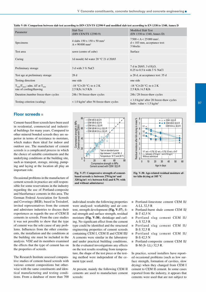
V Concrete constituents, concrete technology and concrete engineering
97
80
60
40
20
0
Compressive strength in MPaCement screed with CEM I 32,5 R
0 20 40 60 80
Com
pres
sive s
treng
th in
MPa
Cem
ent s
cree
d wi
th C
EM II
CEM II/B-S 32,5 RCEM II/B-S 42,5 NCEM II/A-LL 32,5 RCEM II/B-M (V-LL) 32,5 RCEM II/B-M (S-LL) 32,5 R
Test on standard prismAge between 1 d and 56 dTemperature: 10 °C and 20 °C
8
7
6
5
4
3
2
1
0
Age in days20 40 50 60100 30
Resid
ual m
oistu
re af
ter k
iln d
ryin
g in
mas
s % CEM I 32,5 RCEM II/B-S 32,5 RCEM II/A-LL 32,5 RV1
V2
V3
V1: w/c = 0.79; V2: w/c = 0.78; V3 w/c = 0.47c = between 270 kg/m 3 and 310 kg/m3
Without admixture
Floor screeds
Cement-based floor screeds have been used in residential, commercial and industri-al buildings for many years. Compared to other mineral bonded screeds they are su-perior in terms of resistance to moisture, which makes them ideal for indoor and outdoor use. The manufacture of cement screeds is a complicated process in which the choice of suitable constituents and the underlying conditions at the building site, such as transport, storage, mixing, pump-ing and laying at the location all play an important role.
Occasional problems in the manufacture of cement screeds in practice are still respon-sible for some reservations in the industry regarding the use of Portland-composite and blastfurnace cements in this area. The German Federal Association for Screeds and Coverings (BEB), based in Troisdorf, invited representatives from the cement and admixture industries to discuss their experiences as regards the use of CEM II cements in screeds. From the case studies it was not possible to show that the type of cement was the sole cause of any prob-lems. Influences from the other constitu-ents, the installation and the conditions at the building site must be included in the analysis. VDZ and its members examined the effects that the type of cement has on the properties of screeds.
The Research Institute assessed compara-tive studies of cement-based screeds with various cement compositions but other-wise with the same constituents and iden-tical manufacturing and testing condi-tions. From a database of more than 700
individual results the following properties were analysed: workability and air con-tent, strength development (Fig. V-37), fi-nal strength and surface strength, residual moisture (Fig. V-38), shrinkage and curl-ing. No significant effect from the cement type could be identified and the structural engineering properties of cement screeds containing CEM I, CEM II and CEM III/A cements were similar in the laboratory and under practical building conditions. In the evaluated investigations any effects on the test results resulting from tempera-ture, the shape of the test piece or the test-ing method were independent of the ce-ment type used.
At present, mainly the following CEM II cements are used to manufacture cement screeds:
Portland-limestone cement CEM II/ A-LL 32,5 R
Portland-burnt shale cement CEM II/ B-T 42,5 N
Port land s lag cement CEM II / A-S 32,5 R
Port land s lag cement CEM II / B-S 32,5 R
Port land s lag cement CEM II / B-S 42,5 N
Portland-composite cement CEM II/ B-M (S- LL) 32,5 R.
In practice, screed installers have report-ed occasional problems (such as low sur-face strength, formation of cavities, slow drying) when they changed from CEM I cement to CEM II cement. In some cases reported from the industry, it appears that cements were used that are not subject to
Table V-10: Comparison between slab test according to DIN CEN/TS 12390-9 and modified slab test according to EN 1338 to 1340, Annex D
ParameterSlab Test (DIN CEN/TS 12390-9)
Modified Slab Test (EN 1338 to 1340, Annex D)
Specimens4 slabs 150 x 150 x 50 mm³ A = 90 000 mm²
7 500 < A < 25 000 mm², d < 103 mm, acceptance test: 3 blocks
Test area sawn (centre of cube) Surface
Curing 1d mould; 6d water 20 °C 21 d 20/65 –
Preliminary storage 3 d with 3 % NaCl7 d in 20/65, 3 d H2O, 0.25 to 0.5 h with 3 % NaCl
Test age at preliminary storage 28 d ≥ 28 d, at acceptance test: 35 d
Testing direction one side one side
Tmin/Tmax; adm. ∆T at Tmin rate of cooling/thawing
-18 °C/+20 °C; to ± 2 K 2.5 K/h / 6.5 K/h
-18 °C/+20 °C; to ± 2 K 2.5 K/h / 6.5 K/h
Duration /number freeze-thaw cycles 24h / 56 freeze-thaw cycles 24h / 28 freeze-thaw cycles
Testing criterion (scaling) < 1.0 kg/m² after 56 freeze-thaw cycles< 1.0 kg/m² after 28 freeze-thaw cyclesIndiv. value < 1.5 kg/m³
Fig. V-37: Compressive strength of cement-based screeds (c between 270 kg/m³ and 320 kg/m³; w/c between 0.42 and 0.79; with and without admixtures)
Fig. V-38: Age-related residual moisture af-ter kiln drying at 105 °C

VDZ Activity Report 2007 – 2009
98
Fig. V-39: Im-pregnating the concrete road surface with linseed oil
third-party inspection by the VDZ quality surveillance organisation and which were manufactured by companies that do not be-long to VDZ. In some cases it has been re-ported that also “CEM II-M cements” were delivered with no data about the main con-stituents and without a conformity certifi- cate or the national compliance marks. These products should not be used.
The meetings between the German Ce-ment Works Association (VDZ), the Ger-man Federal Association for Screeds and Coverings (BEB) and the Federal Special-ist Group for Screeds and Coverings in the Central Association of the German Con-struction Industry (ZDB) in May 2008 re-sulted in a joint statement – “Information to manufacture cement-based screeds.” This statement paves the way for ensuring and disseminating high-quality methods for us-ing cement screeds. In line with this, VDZ in collaboration with BEB and representa- tives of the cement and admixture industries examined the issues associated with the manufacture of cement screeds in relation to the different influences. The effects of the constituents and also of the manufacturing process, the installation and the conditions on the building site were all considered. The basis for manufacturing screeds is the list of requirements in DIN EN 13813 as regards the construction method and the specific building project. Screed installers generally check the suitability of the screed composition with the planned constituents in the initial test at a working consistency normally found on building sites. If unde-sired screed properties (such as inadequate workability, inadequate strengths) are iden-tified, suitable measures must be taken to improve the quality of the screed mortar.
These measures include choosing a dif-ferent aggregate (quality, supplier, grad-ing curve), a different screed admixture (type of admixture, admixture manufactur-er, amount of admixture) or a different ce-ment (cement type, cement manufacturer, cement strength class) or changing the mix-ing ratio of the mortar and extending the af-ter-treatment and the length of time that the screed must not be walked upon. The results of the collaboration between VDZ and BEB are contained in instruc-tions for the manufacture of cement screed mortars.
Traffic route engineering
It is expected that the amount of traffic on European roads will continue to increase in the long term; this is especially true for heavy transport. Despite the expansion of rail networks throughout Europe, a large proportion of the goods will still be moved by road. It is thus an advantage to have du-rable, low-maintenance construction meth-ods that allow traffic to flow smoothly with-out any hindrances, for example due to road works. Within the scope of the infrastruc-ture programme from 2009 funding will be provided to develop infrastructure fa-cilities. Concrete construction methods are characterised by high load-bearing capaci-ties and stability against deformation, low maintenance costs and a long service life and have, in the past, mainly been used to build major roads with a high proportion of heavy goods traffic. Concrete construc-tion methods are also to be extended to cover the area of municipal road building. An important requirement for the planned expansion of the application areas is that
the concrete structures are extremely du-rable. Because of this, durability has been one of the focuses of the Research Insti-tute’s activities.
Alkali-Silica ReactionDuring the period under review the new version of the Alkali Guidelines from the German Committee for Structural Concrete (DAfStb) “Preventive measures against damaging alkali reactions in concrete” was adopted. Road surfaces made from con-crete in Classes SV and I to III are to be classified in moisture class “moist + exter-nal alkali supply + strong dynamic stress” (WS), road surfaces in Classes IV to VI are to be classified in the moisture class “moist + external alkali supply” (WA). In addi-tion, TL Beton-StB 07 contains require-ments for the cements and aggregates for concrete road surfaces (see article on Al-kali-Silica Reaction). The measures taken there should prevent the occurrence of a damaging alkali-silica reaction (ASR) in future. Early measures to maintain road surfac-es already damaged as a result of an ASR could possibly prolong their service life. A working group from the German Feder-al Ministry of Transport with the partici-pation of the Research Institute compiled a list of technical options to maintain these concrete road surfaces. The targeted use of suitable measures should extend the life of the affected roads and avoid them hav-ing to be renewed prematurely. The meas-ures were defined in relation to the degree of damage.
Three damage categories were formed: 1: start of crack formation, 2: serious cracking and 3: very serious cracking and concrete breaking off (loss of load-bearing capac-ity). Road surfaces in damage categories 2 and 3 have to be covered with asphalt in varying thicknesses to improve their load-bearing capacity. The effectiveness of oth-er measures is to be investigated for road surfaces in Category 1, with only shallow cracks and where the load-bearing capac-ity is not reduced. For this purpose, a test section was set up on the A14 motorway in Germany (built in 2000). The road surface has two layers in which a reactive aggre-gate was used in the top course concrete. Various test sections were set up in sum-mer 2008. Two different methods were in-vestigated which are used in road mainte-nance to e.g. improve grip: a bitumen emul-sion applied as DSK slurry surfacing and an epoxy resin coating. DSK slurry or coating was applied to the road surface and then a

V Concrete constituents, concrete technology and concrete engineering
99
Fig. V-40: Con-crete round-about in Bad Sobernheim
polishing-resistant aggregate was spread over the surface. Two sections were also impregnated with linseed oil (Fig. V-39) and a hydrophobing agent respectively. With these four variants the moisture ab-sorption of the concrete was reduced. If the effect is long term, this removes the con-ditions for a damaging ASR – swelling of the gel that occurs as a result of water ab-sorption. In another variant the surface of the concrete road was treated with a lithi-um nitrate solution. Lithium bonds much better to the alkali-silicate gels than sodi-um or potassium. The gel that is formed does not swell as much when it comes in-to contact with water. A requirement is that the lithium can penetrate sufficiently deep into the roughly 7 cm thick damaged top course concrete. The fundamentals for lithi-um treatment were developed in a previous research project carried out by the Research Institute for the German Federal Ministry for Transport, Building and Urban Devel-opment (BMVBS). To assess the success of the measures, the test sections and ad-ditional reference sections are being moni-tored by the Federal Highway Research In-stitute (BASt). Crack development is deter-mined at various points in time.
Concrete in municipal road construction Areas of application for concrete road sur-faces in the municipal area are, for exam-ple, roundabouts, bus stops and bus lanes, inner-city crossings, heavily used approach roads in major cities and also whitetop-ping, where a concrete overlay is applied to an existing asphalt surface. So far, there has been little use of concrete construction methods in these areas, which would sug-gest that there is a lot of potential. Conse-quently, pilot projects are to be carried out for the named areas to gather experience in all phases from planning through to im-plementation. The planned equipment engi-neering has to be adapted to suit the respec-tive local conditions. If necessary, a part-ner-like cooperation should be established with the local concrete suppliers. The con-struction work can be carried out by re-gional construction companies. The only requirement is that these companies have sufficient experience in concrete construc-tion. Upon completion of the pilot projects the knowledge gained from them should be documented and published.
One example of a successful pilot project is the first concrete roundabout in Germa-ny, which was built in 2008 (Fig. V-40). Concrete roundabouts are now widespread in Austria, Belgium, the Netherlands and Switzerland.
Regulations To achieve a standard design of the con-tractual fundamentals in terms of the spe-cial needs of municipal road construction, it would be advantageous to adapt the reg-ulations (TL and ZTV Beton-StB 07). Suit-able codes of practice should be drafted, for roundabouts for example. Experience has shown that this makes implementation much easier.
Modelling On the basis of 50 normal cements manu-factured in Germany with different compo-sitions, investigations were carried out in the Research Institute within the scope of AiF research project no. 14767 N to iden-tify the boundary conditions under which it is possible to calculate the standard com-pressive strength of 28-day old cement based on key cement data with the help of the Virtual Cement and Concrete Testing Laboratory (VCCTL) software product.
The input data for the simulation calcu-lation were chemical-mineralogical and physical parameters of cement and aggre-gate as well as key data that was determined by digital image analysis (e.g. clinker phase distribution). The simulation calculations were compared with the results from the experimental investigations (e.g. hydration heat, composition of the pore solution, po-rosity, compressive strength).
Simulation of cement hydrationAge-related simulation of cement hydra-tion was carried out through iteration un-til a desired end point. The connection
between the iteration steps and the actu-al progress of hydration was calculated in VCCTL for every cement via a time con-version factor, which determines the time comparison with the measured hydration heat. To simulate compressive strength af-ter 28 days, as late a time as possible was chosen for the comparison, the hydration heat values after seven days.
Fig. V-41 shows the progress of hydration heat for two Portland cements CEM I 32,5 R from different origins. The 7-day compar-ison of the simulated hydration heat to the hydration heat determined by heat flow ca-lorimetry (TAM) produced with some ce-ments (Fig. V-41, left) a good correlation with the hydration heat trend while with others (Fig. V-41, right) the correlation was not so good.
The simulated hydration heat trend devi-ated from the measured hydration heat in many cements. In many cases the simulat-ed development of hydration heat was well above the measured hydration heat. In these cases the simulated hydration proceeded faster than the actual hydration.
In the investigation as to whether groups of cements could be aggregated for the simu-lation calculations by choosing certain pa-rameters, no direct connection between the strength class and the time conversion fac-tor was identified.
While the simulation calculations for the effect of the tricalcium silicate content on compressive strength largely matched the experience values, the effect of sulphate agents on hydration heat development did not meet expectations.

VDZ Activity Report 2007 – 2009
100
Fig. V-41: Hydration heat of two Portland cements CEM I 32,5 R from different origins simulated and determined using heat flow calorimetry (TAM); left good, right less good correlation of the hydration heat after comparison with the 7-day value (168 h)
SimulationTAM-1TAM-2
400
300
200
100
00 24 48 72
Age in h
Hyd.
hea
t in
J/g
96 120 124 168
400
300
200
100
00 24 48 72
Age in h
Hyd.
hea
t in
J/g
96 120 124 168
SimulationTAM-1TAM-2
With some cements, simulation of the com-position of the pore solution produced sul-phate and calcium ion concentrations in the pore solution that were clearly too high. Even when the sulphate agent was fully consumed with these cements, the simulat-ed sulphate ion concentration in the pore solution remained at almost the same level. The programme code needs to be examined as regards consideration of the setting regu- lator types.
PorosityThe porosities for cement paste aged 7 and 28 days determined with mercury intrusion were up to 10 % by volume above the re-spective values of the simulation calcula-tion. Among other things, this can be at-tributed to the fact that only “capillary po-rosity” is contained in the VCCTL pro-gramme. In many cases, the pore volume determined with mercury intrusion po-rosimetry was ≥ 0.01 µm of the simulat-ed porosity. The measured porosities of standard mortar were, as expected, well be-low the measured porosity of the respec-tive cement paste. In contrast, the mor-tar porosity simulated with VCCTL more or less matched the simulated porosity of the respective cement paste. This allows the conclusion to be drawn that the poros- ity of mortar has not been simulated cor-rectly to date.
Compressive strengthSimulation of cement hydration provid-ed the composition of the structure and, consequently, data about the space filling behaviour of the hydration products X(t) and about porosity P(t). With the help of Powers' approach, which assumes a basic strength of the structure D0 which is re-duced by porosity, the course of the com-
pressive strength was calculated using the following equations
D(t) = D0 · X (t)n1 and D(t) = D0 · (1 – P(t))n2))
The measured compressive strengths of ce-ment paste and standard mortar were com-pared with the corresponding simulated de-velopment of compressive strength. To re-flect the measured development of com-pressive strength by means of the simulated development of compressive strength, for each cement the variables D0 and n had to be determined separately on the basis of the measured compressive strengths. Com-pared to the values D0 = 203 MPa and n = 4.67 mentioned by Locher, the compres-sive strength of the pore-free cement paste D0 and also the variable n were lower for most of the investigated cements. No gen-eral values for D0 or n to approximate the development of compressive strength in different cement types and strength class-es could be derived.
Alternatively, with the VCCTL software it is possible to calculate compressive strength on the basis of correlations with the modulus of elasticity independently from the simulated porosity. The values of the modulus of elasticity from the simula-tion calculations were, on average, about 2.6 GPa above the measured values. The compressive strengths measured on the basis of the simulated modulus of elastic-ity were below the measured compressive strengths and correlated with the simu- lated high porosities of standard mortar but not with the simulated high modulus-es of elasticity.
Consideration of the aggregateTo investigate the deviations between the simulated porosity and the calculated com-pressive strength and the corresponding measured value for standard mortar, the influence of various parameters were con-sidered to take account of the aggregate in simulation calculations.
On the whole it became clear that especial-ly the choice of the modulus of elasticity for the aggregate, the particle size distribution of the standard sand and the size and prop-erties of the contact zone are important fac-tors for the simulation calculation of com-pressive strength after 28 days.
SummaryTo summarise, it can be said that the simu-lation of the development of compressive strength in standard mortar up to 28 days old could not be predicted reliably for the different cements without using informa-tion concerning the aggregate.
Apart from the parameters of the cements used, the parameters of the aggregate and the transition zone from stone to unaffect-ed cement matrix are also important for the result of the simulation. Simply vary- ing these parameters within the normal fluctuation range can have a serious effect on the result of the simulation.
Basically, the VCCTL model seems suit-able for mapping hydration of cement. However, the software requires further development especially in terms of simu-lating porosity of mortar and the compo-sition of the pore solution and also as re-gards the influence of sulphate on the hy-dration process.

V Concrete constituents, concrete technology and concrete engineering
101
Table V-11: Exposure class-related requirements for a planned life of at least 50 years in terms of the minimum and maximum values and the most frequently used value for minimum concrete cover, the minimum compressive strength class, the maximum permissible water-cement value and the minimum cement content
Exposureclass
Minimum con-crete cover,
mmMinimum compressive strength class
Maximum permissible water-cement value
minimum cement content in kg/m³
min max min max m.f.u.v. min max m.f.u.v. min max m.f.u.v.
XC1 10 20 NS C25/30 C20/25 0.60 NS 0.65 NS 300 260
XC2 15 35 NS C28/35 C25/30 0.55 NS 0.60 150 300 280
XC3 10 35 NS C32/40 NS, C25/30 0.45 NS 0.55 150 340 280
XC4 15 40 NS C32/40 NS 0.45 NS 0.50 150 340 300
XD1 25 40 NS C40/50 C30/37 0.45 0.60 0.55 150 360 300
XD2 25 55 NS C40/50 C30/37 0.40 0.550.50, 0.55
150 360 300
XD3 33 55 NS C50/60 C35/45 0.40 0.45 0.45 150 400 320
XS1 25 40 NS C40/50 C30/37 0.45 0.550.50, 0.45
150 360 300
XS2 25 45 NS C40/50 C35/45 0.40 0.55 0.45 150 360 320, 360
XS3 30 50 NS C50/60 C35/45 0.35 0.45 0.45 150 400 320
XF1 – – NS C32/40 NS 0.55 0.60 0.60 NS 300 300
XF2 – – NS C35/45 NS 0.45 NS 0.55 NS 340 300
XF3 – – NS C40/50 NS 0.45 0.60 0.50 NS 340 300, 320
XF4 NS C40/50 NS 0.40 NS 0.45 NS 400 340
XA1 – – NS C35/45 NS 0.40 0.60 0.55 150 380 300
XA2 – – NS C40/50 C35/45 0.40 0.50 0.50 150 380 320
XA3 – – NS C40/50 NS, C35/45, C40/50 0.35 0.45 0.45 150 400 360
m.f.u.v.: most frequently used valueNS: No specification
Standardisation
The European concrete standard EN 206-1According to the CEN regulations, CEN standards have to be routinely reviewed every five years. For European concrete standard EN 206-1 this review would have been due in 2005. However, since at that time the standard had not yet been applied in some EU countries and in oth-ers had only recently been adopted, the re-sponsible bodies had little experience with the standard. Consequently, it was decid-ed that there would be little point in CEN/TC 104, “Concrete and related products” reviewing EN 206-1 before 2010. This de-cision was confirmed at the CEN meetings in Larnaca in November 2005 in the corre-sponding resolutions.
A working group of CEN/TC 104/SC1 “Concrete” has developed a synopsis of the national application documents (NAD) for the European concrete standard EN 206-1. This synopsis has made it clear that it will
be almost impossible to further standard-ise definitions that are relevant to durabil-ity. Table V-11 provides an overview of the requirements in terms of minimum and maximum values and the most frequently used values as regards minimum concrete cover, the minimum compressive strength class, the maximum permissible water-ce-ment value and the minimum cement con-tent. The most frequently used value is the value that has been chosen by more CEN member states than any other; but this should not immediately be interpreted as meaning that this value is actually used by most CEN member states. The following conclusions were drawn:
In the majority of cases the values used most frequently for the maximum per-missible water-cement value and the minimum cement content correspond to the values recommended in EN 206-1, Table F.1.
In five cases (XC1, XC2, XC4, XD1 and XD3) the most frequently used values for the minimum compressive strength
class, the maximum permissible water-cement value and the minimum cement content in all three categories match the values recommended in EN 206-1, Ta-ble F.1.
In Denmark, where the lowest minimum cement contents are prescribed, compli-ance with a minimum powder content is also required. In Denmark, the mini-mum cement content cannot be reduced if Type II additions are used.
At its meeting in Stockholm in June 2007, CEN/TC 104/SC1 defined a road map for further revision of the European concrete standard EN 206-1. In June 2008, CEN/TC 104/SC1 put the road map into more specif-ic terms. For the revision date in 2010 sta-tus papers have been compiled for issues such as the equivalent durability concept, the use of concrete additions, conformity assessment of concrete and alkali-silica re-actions (ASR). These papers are the corner- stones for the subsequent new version of the standard.

VDZ Activity Report 2007 – 2009
102
Principles for revision of European concrete standard EN 206-1
Equivalent durability procedure (EDP)The concept described in Annex E of EN 206-1 has hardly been applied anywhere in Europe to date. The Dutch system of so-called “Attestbeton” or certified concrete could be described as an exception. The concept according to Annex E can be used to prove that the performance (essentially the durability) of concrete with additions is at least equivalent to a reference composed according to the descriptive rules (min c, max w/c, etc.) of the corresponding nation-al annex. In Germany, this principle can on-ly be applied within the scope of national technical approvals from the German Insti-tute for Building Technology (DIBt). In the course of the revision it is now to be exam-ined to what extent the procedure described in Annex E, which has so far been limited to proof for concrete additions, could be used in case of deviations from the descriptive approach and, at the same time, how this procedure can be put into more specific terms. This includes defining the reference situation (“reference concrete”) and the is-sue of which test methods are suitable and generally acceptable. The aim is to discover both opportunities (proof of equivalent du-rability of new concrete constituents) and challenges (softening well-tried and proven descriptive rules or negative assessments of solutions that have been proven in prac-tice). The principle of equivalent durabil-ity should not be confused with the con-cept described in the UK concrete stand-ard: the combinations principle. In the com-binations principle, defined combinations of certain cements and concrete additions
Equivalent durability procedure (EDP) – Regulation for durability-relevant aspects – Application possible only if put into force nationally (definition of a “reference concrete”)
Type II additions – The currently standardised additions, fly ash, silica fume and ground-
granulated blastfurnace slag are handled – The k-value concept can be used for all Type II additions – Cements with several main constituents should be considered
In principle, the regulations for conformity assessment and production control for concrete should remain unchanged
Alkali-Silica Reaction – No general classification of aggregates at an European level – Preventative measures regulated nationally
are to be inspected; largely corresponding to the inspection prescribed in EN 197-2. The “equivalence” of combinations of Port-land cement together with GGBS, fly ash or limestone meal with cements of a suit-able composition is implied on the basis of the results of a strength test pursuant to EN 196-1. Even if it is accepted that this procedure can be used only for known combinations of Portland cement and ad-ditions, in Germany it is inconceivable at the present time that it could be applied without an initial test and the correspond-ing durability tests. Apart from that, further national technical approvals would be re-quired. The following principles were de-fined for the revision:
A principle of equivalent durabili-ty should be included for all exposure classes.
A detailed description will be possible for exposure classes XC, XD and XS.
The option of specifying performance (= durability) directly on the basis of limit values should still be available. EN 206-1 may possibly recommend the test methods but will not specify any values.
The concept can be used only when a CEN member state has defined its “ref-erence concretes”.
Concrete additionsThe general suitability of concrete additions for manufacturing concrete according to EN 206-1 is proven for stone dusts accord-ing to EN 12620, pigments according to EN 12878 (almost inactive additions Type I),
the pozzolanic concrete additions fly ash according to EN 450-1 and silica fume ac-cording to EN 13263-1 (Type II). Type II additions may be counted together with the cement content and the water-cement value if they have been proven to be suit-able in the concrete composition (k-value approach). The suitability of this approach is deemed to have been proven for fly ash and silica fume. However, the k-value approach in the form described in EN 206-1 is not used in many countries – and also not in Germany. Thus, the aim should be to get a general description and extend this to ce-ments with several main constituents. The future EN 206-1 should also contain a ref-erence to the European product standard for granulated blastfurnace slag, EN 15167-1. Apart from the k-value approach, which most countries with a national applica-tion rule have chosen for GGBS as a con-crete addition, the principle of the equiva-lent durability concept and the UK combi-nations concept should also be examined. The following principles have been defined for the revision:
The k-value concept and the equiva-lent durability concept will remain un-changed.
General aspects of the combinations concept used in the UK should be add-ed.
A reference to GGBS should be made in combination with the above-mentioned concepts.
The concepts for using additions should be described together with CEM II ce-ments and in a general form. Detailed rules for their use will continue to be regulated nationally.
Alkali-Silica Reaction (ASR)To coordinate further activities in regard to ASR (see section on Alkali-Silica Re-action), a joint working group of the CEN standardisation committees for cement and building lime (TC 51), aggregates (TC 154) and concrete (TC 104) has been set up un-der the leadership of the Research Institute of the Cement Industry. The working group makes the following recommendations:
A (complete) specification to prevent damaging ASR is not possible within the scope of European concrete stand-ard EN 206-1. Only principles can be described.
Alkali reactivity of aggregates can be classified only on a national level.
EN 206-1 cannot contain any limit values for effective alkali contents in concrete, as this requires a classification of aggre-gate combinations with consideration of national experience.

V Concrete constituents, concrete technology and concrete engineering
103
A2 and A3 changes to DIN 1045-2The European concrete standard EN 206-1 “Concrete – Part 1: Specification, per-formance, production and conformity; Ger-man version of EN 206-1:2000” allows as a non-mandated and, thus, non-harmo-nised standard National Application Doc-uments (NAD) with various sections in order to take account of different climat-ic and geographical conditions, different protection levels and long-established re-gional customs and experience. In Germa-ny, these National Application rules are de-fined in DIN 1045-2. The national stand-ards committee on concrete technology has voted on a list of changes to be made to DIN 1045-2. This was necessary due to application experience and the updating of other product standards for concrete con-stitu-ents and their national application reg-ulations. The A2 changes were published in June 2007.
Within the scope of the A2 changes the standard was revised with regard to the following points:
Adaptation to the new and revised Euro-pean standards for concrete constituents In the meantime, European standards for silica fume (EN 13263) and an amended version of the standard for fly ash (EN 450) have been published. Reference is made to these standards. The application regulations from the drafts of the E DIN V 20000-106/107 series of standards envisaged for Ger-many in terms of the environmental compatibility of fly ash and the appli-cation regulations for silica fume and silica suspensions have been adopted.
K-value concept for fly ash also in expo-sure classes XF2 and XF4 for frost at-tack with de-icing agents and the corre-sponding change to the application reg-ulations for cements containing fly ash It is now also possible to use the k-value concept for fly ash for exposure classes XF2 and XF4 (frost with de-ic-ing agent) with the known regulations. In this connection the use of cements containing fly ash is no longer exclud-ed in these and other exposure class-es. For example, in the past if Port-land-fly ash cement CEM II/A-V or Portland-composite cement CEM II/A-M (P-V) were used in concrete for ex-posure class XF3, it was not permis-sible use the k-value concept with fly ash used as a concrete addition for the water-cement value or for the mini-mum cement content. This restriction no longer exists, nor do the usage re-
strictions for CEM II/A-V in expo-sure classes XF2 and XF4 or CEM II/B-V in exposure classes XF2, XF3 and XF4. In addition, CEM II/A-M (S-V) and CEM II/A-M (V-T) can now be used in concretes according to DIN EN 206-1 and DIN 1045-2 with no restrictions. For cements CEM II/B-M (D-V) and CEM II/B-M (P-V) there is no long-er any restriction on use for exposure class XF3. The application regulation for fly ash as a concrete addition goes further than the ZTV-ING regulations. In these regulations fly ash can be count-ed only for exposure class XF2 and only for tunnel construction. In the ZTV-ING area, the “saturation value“ of the concrete must also be determined with-in the scope of an extended initial test (see ZTV-ING, Part 3 “Massive Con-struction”, Section 1 “Concrete”, Par-agraph 3.2 (7) “Use of additions“).
Consideration of the definitions of the Al-kali Guidelines from the German Com-mittee for Structural Concrete (DAfStb). Integration of the moisture classes on the basis of the exposure classes The German Committee for Structural Concrete (DAfStb) has revised and is-sued a new version of the “Alkali Guide-lines”. The regulations were integrated into the respective points of DIN 1045-2/A2. The so-called moisture class must now be stated in the definition of a con-crete. The “Exposure Class” table of DIN 1045-2 has been supplemented by a corresponding section for the moisture classes of the “Alkali Guidelines” (see section on “Alkali-Silica Reaction“). Since the customer must state the mois-ture class for every definition of a con-crete, consequently, the ready-mixed concrete delivery specification must also contain the moisture class. In future, every ready-mixed concrete deliv-ery ticket must include the moisture classes that are possible for the respec-tive concrete (WO, WF, WA or WS). In the past, this was necessary only in the “core application area“ of the Al-kali Guidelines (e.g. North Germany).
Consideration of fibres according to European standard EN 14889-1/2. Fibres for concrete (steel fibres and poly- mer fibres) have now been standardised throughout Europe. Use in concrete ac-cording to EN 206-1/DIN 1045-2 will be allowed with the A2 change. Fi-bres according to this standard may be added to the concrete; however, their load-bearing effect may not be con-sidered. Further national technical ap-
provals are required here; for instance, in the same way as steel fibres are to be considered in a DAfStb guideline. With the A2 change general informa-tion is provided for handling and add-ing fibres based on the regulations for additions. Polymer fibres and steel fi-bres formed into bundles in a metering package (paper bags) require nation-al technical approval proving that they mix evenly throughout the concrete.
Stating the sulphate content of the groundwater in exposure class XA when the concrete is specified and ordered. Another footnote has been included in Table 2 of DIN 1045-2. According-ly, in exposure class XA and with sul-phate concentrations above 600 mg/l in the groundwater, the customer must state the sulphate content when spec-ifying the concrete. The ready-mixed concrete manufacturer can then choose a suitable cement with a high sul-phate resistance (HS-cement), take ac-count of the regulations for the use of fly ash and identify the concretes in the delivery documents accordingly.
Adapting the procedure to determine strength development in a concrete in case of a proof age for compres-sive strength other than 28 days. The regulations from the DAfStb guide-line for “Massive concrete construc-tion components“ have been adopted If in special applications the compres-sive strength of a concrete is determined after more than 28 days, for these con-cretes the calculation of strength de-velopment (see DIN 1045-2, Tab. 12, r-value) must be adapted. Strength de-velopment should then be determined from the ratio of average compressive strength after two days and the aver-age compressive strength at the time the compressive strength is determined. That means that it is not the strength after 28 days that is used for the calculation, but rather the value after 56 or 91 days. This procedure corresponds with the regulation that was already introduced in the DAfStb guideline for “Massive concrete construction components”.
Integration of the A1 changes to DIN 1045-2 from 2005. The A1 changes already published in 2005 have been adopted and integrated into the A2 changes.
The following points were implemented in another change (A3 change):

VDZ Activity Report 2007 – 2009
104
The previous standards DIN V 20000-100 (application regulations for con-crete admixtures), DIN V 20000-103 (application regulations for aggregates) and DIN V 20000-104 (application reg-ulations for lightweight aggregates) have been adopted;
Supplementary definitions from the Technical Construction Regulations (e.g. for pigments) and the list of con-struction rules were integrated into the A3 change;
Application regulations for cements ac-cording to DIN EN 197-1, German ver-sion of EN 197-1:2001+A1:2004+A2 (SR cements) +A3 (fly ash) have been adopted.
As an application regulation for the SR cements the following comment has been added at the appropriate places: “Until DIN EN 197-1/A2 is available, the definitions in DIN 1164-10 must be complied with for HS cements. As soon as E DIN EN 197-1/A2 can be used, the requirements for HS ce-ments are deemed to be fulfilled if a cement with high sulphate resistance according to E DIN EN 197-1/A2 (CEM I-SR 3 or low-er, CEM III/B-SR, CEM III/C-SR) is used.“ Cements containing fly ash used to manu-facture concrete according to DIN 1045-2 may contain only fly ash with up to 5% loss on ignition.
A consolidated version of DIN 1045-2 was published in August 2008. This now con-tains the A2 and A3 changes to DIN 1045-2:2001-07 and the requirements from DIN V 20000-100, DIN V 20000-103, DIN V 20000-104, DIN V 20000-106 and DIN V 20000-107. The changes to DIN 1045-2:2001-07, resulting from DIN 1045-2/A2:2007-06, E DIN 1045-2/A3:2008-01 and the results of the consultations re-garding objections to E DIN 1045-2/A3 are marked with vertical lines beside the text. In addition, changes were made to the standard references to take account of the current status of the reference documents; however, these are not marked. An updat-ed version of DAfStb booklet 526 will be published some time in 2009.
DAfStb Guideline “Massive concrete construction components“The reason for the revision of the guide-line was the new issue of DIN 1045, Parts 1 to 3, in August 2008. Use of the k-value concept for fly ash also in exposure class-es XF2 and XF4 for frost attack with de-ic-ing agents (see above) as described in DIN 1045-2:2008-08 was transfered to con-
crete compositions for massive construc-tion components.
Fire protection
In terms of fire protection, a distinction is generally made between preventive and defensive fire protection. Defensive fire protection applies only when a fire has al-ready started and essentially covers the fire brigade's work in extinguishing the fire. In contrast, preventive fire protection is used to prevent or limit the start or spread of fires. In addition to technical fire pro-tection, which in particular includes fire alarm systems and automatic fire extin-guishing systems, structural fire protection is one of the crucial pillars for the neces-sary level of safety in the area of preven-tive fire protection. Structural fire measures are permanent and offer the required lev-el of protection without having to be trig-gered by operational or mechanical pro- cesses, which always harbour a risk of fail-ure. Defensive fire protection depends on the deployment of the fire brigade, where there is also a risk of failure.
Concrete structural elements are a relative-ly simple way of fulfilling fire protection requirements and usually involve no major additional expenditure. The non-flammable construction material, concrete, can be used to build structural elements with a high re-sistance to fire and with a corresponding-ly stable shielding effect. This means that in the event of a fire, concrete structures retain their stability for a long time and that fires can be restricted to confined are-as. These fire protection properties of con-crete and concrete building members con-tribute to safety for human life, which has top priority in statutory fire protection re-quirements. However, saving the building itself or the contents of the building are also important in terms of protecting assets. Even if legislation has made protection of property the personal responsibility of the building owner and users, saving assets is in the interest of both private individuals and the general public. Furthermore, structural fire protection measures also protect the en-vironment if effective fire limitation reduc-es smoke and gas emissions as well as the amount of extinguishing water that is need-ed and when the extinguishing water, which is generally contaminated, can be retained. National regulations (Germany)DIN 4102 “Fire behaviour of building materials and building components“VDZ participated in the development of the A2 change to DIN 4102-4 “Synop-
sis and application of classified building materials, components and special com- ponents“ and the A1 change to DIN 4102-22 “Application standard for DIN 4102-4 based on the design of partial safety fac-tors“. Both parts of the standards and a con-solidated version, containing both parts are to be published in the second quarter of 2009 as a “yellow print”.
In addition to a new section dealing with the fire behaviour of construction compo-nents made from high strength concrete, one of the main changes compared to the last version of the standard is the revision of a design table for reinforced concrete columns made with normal-weight con-crete. The underlying conditions for the use of this revised table exclude its appli-cation for cantilever columns. However, since the fire design of cantilever columns is very important in practice (e.g. for fac-tory buildings), the Institute for Construc-tion Materials, Concrete Structures and Fire Protection at Braunschweig Universi-ty in Germany was commissioned to devel-op a simplified calculation method to verify the fire resistance class F90 for cantilever columns. This research project, which was supported by VDZ, was completed in No-vember 2008 and the method can thus be included in the revised DIN 4102.
DIN 18230-1 “Structural fire protec-tion in industrial buildings – Part 1: Analytically required fire resistance time“DIN 18230-1 defines a calculation pro- cess with which the technical fire protection design of supporting components in indus-trial buildings can be carried out. It is based on the proof that the construction compo-nents meet the required fire resistance time. The yellow print of a new version of DIN 18230-1 was published in 2008. One im-portant change compared to the 1998 ver-sion is the introduction of the term “lev-el” in industrial buildings: while by defi-nition floors are separated from each oth-er in terms of technical fire protection and each forms a separate fire compartment, levels can also have open spaces or can be made up from partial sections. The area of a fire compartment is then calculated from its floor area and the total area of the levels above it. According to the new DIN, platforms or scaffolds without the required fire resistance time are no longer counted as part of the calculated area and the fire load of these areas is added to the next cal-culable area below. This represents a tight-ening of the regulations.
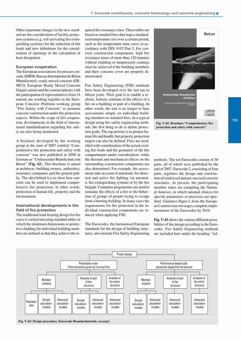
V Concrete constituents, concrete technology and concrete engineering
105Fig. V-42: Brochure “Comprehensive fire protection and safety with concrete”
Fig. V-43: Design procedure (Eurocode-Brandschutzteile, excerpt)
Project design
Tabulated data
Simplecalculation
models
Simplecalculation
models
Advanced calculation
models
Simplecalculation
models
Advanced calculation
models
Advanced calculation
models
Advanced calculation
models
Advanced calculation
models
Advanced calculation
models
Performance-based code (physically based thermal actions)
Analysis of part of the
structure
Member analysis
Analysis of the entire structure
Member analysis
Analysis of part of the
structure
Analysis of the entire structure
Prescriptive rules (Thermal actions given by nominal fire)
Other important changes in the new stand-ard are the consideration of facility protec-tion systems (e.g. self-activating fire extin-guishing systems) for the reduction of fire loads and new definitions for the consid-eration of openings in the calculation of heat dissipation.
European cooperation The European associations for precast con-crete (BIBM, Bureau International du Béton Manufacturé), ready-mixed concrete (ER-MCO, European Ready Mixed Concrete Organi-sation) and the cement industry with the participation of representatives from 14 nations are working together in the Euro- pean Concrete Platform working group “Fire Safety with Concrete” to promote concrete construction under fire protection aspects. Within the scope of this coopera-tion, developments in the field of interna-tional standardisation regarding fire safe-ty are also being monitored.
A brochure developed by the working group at the start of 2007 entitled “Com-prehensive fire protection and safety with concrete” was also published in 2008 in German as “Umfassender Brandschutz mit Beton” (Fig. 42). This brochure is aimed at architects, building owners, authorities, insurance companies and the general pub-lic. The idea behind it is to show how con-crete can be used to implement compre-hensive fire protection; in other words, protection of human life, property and the environment.
International developments in the field of fire protectionThe traditional load-bearing design for fire cases is carried out using standard tables in which the minimum dimensions or protec-tive cladding for individual building mem-bers are defined so that they achieve the re-
quired fire resistance class. These tables are based on standard fires that map a standard-ised temperature rise over a certain period, such as the temperature-time curve in ac-cordance with DIN 4102 Part 2. For con-crete construction components, high fire resistance times of more than 120 minutes without cladding or intuprescent coatings must be achieved if the building members and their concrete cover are properly di-mensioned.
Fire Safety Engineering (FSE) methods have been developed over the last ten to fifteen years. Their goal is to enable a re-alistic, holistic estimate of the effects of a fire on a building or part of a building. In other words, the aim is no longer to base assessments simply on individual build-ing members or standard fires. In a typical design using fire safety engineering meth-ods, the first thing to do is define protec-tion goals. The top priority is to protect hu-man life and health; but property protection targets can also be defined. Fires are mod-elled with consideration of the actual exist-ing fire loads and the geometry of the fire compartments under consideration, while the thermal and mechanical effects on the surrounding construction components are also determined. For example, the assess-ments take account of automatic fire detec-tion and active fire fighting via automat-ic fire extinguishing systems or by the fire brigade. Computer programmes are used to simulate the effects of a fire or the behav-iour of groups of people trying to escape from a burning building. In many cases the requirements for fire protection in the in-dividual construction components are re-duced when applying FSE.
The Eurocodes, the harmonised European standards for the design of building struc-tures, also include Fire Safety Engineering
methods. The ten Eurocodes consist of 58 parts, all of which were published by the end of 2007. Eurocode 2, consisting of four parts, regulates the design and construc-tion of reinforced and pre-stressed concrete structures. At present, the participating member states are compiling the Nation-al Annexes, in which national choices for specific parameters or processes are spec-ified. Guidance Paper L from the Europe-an Commission envisages complete imple-mentation of the Eurocodes by 2010.
Fig. V-43 shows the various different possi-bilities of fire design according to the Euro- codes. Fire Safety Engineering methods are included here under the heading “Ad-

VDZ Activity Report 2007 – 2009
106
Fig. V-44: AVR experimental reactor with material lock (left) and con-struction site tent to fill the reactor cham-ber (right)
vanced Calculation Models”. The decision as to whether use of advanced calculation models is permitted in a member state is regulated in the National Annexes. Many member states allow use only with restric-tions. For example, it is defined that use is limited to experts with adequate experi-ence. The concrete and cement industries welcome these restrictions, as improper use of FSE can easily result in faulty assump-tions in the calculations, which, in turn, can lead to requirements being wrong-ly defined.
Within the scope of the European cooper-ation at the European Concrete Platform (ECP) level, the European Cement Re-search Academy (ECRA) has taken over an important role and will now active-ly support further work on the Eurocodes concerning concrete and fire protection in the corresponding standardisation com-mittees. In addition, the National Annexes to Euro-code 2, Parts 1-2, which regulates fire safety designs of concrete structures, will be assessed and compared to encour-age more harmonisation in Europe.
Consultancy and expert advisory services
Demand for concrete technology consul-tancy and expert advisory services rendered by the Research Institute of the Cement In-dustry has increased considerably over the past years. This principally applies to the following key areas:
Development of optimised concrete and mortar mixes for the respective clients’ area of application,
Structural analyses and assessments,
Development of repair concepts, Clarifying issues related to alkali-silica
reactions and assessing aggregates (see section on Alkali-Silica Reaction)
Chemical attacks on concrete.
Experts in all areas of concrete engineering who are represented on the corresponding national and international committees and who have extensive experience from labora- tory and practical work find efficient solu-tions to what are sometimes very complex problems. The interdisciplinary coopera-tion with experts in the fields of mineral-ogy, chemistry, physics and applied tech-nology in the other departments of the Re-search Institute is a particular advantage in this connection.
Below we would like to present a project concerned with developing optimised con-crete and mortar mixes in which the con-crete engineering support of the Research Institute was requested. In particular, the Institute’s extensive experience in research work and the development of self-compact-ing concrete as well as experience in the area of special concretes helped it devel-op efficient solution proposals.
Filling the experimental reactor of AVR GmbHThe experimental nuclear power plant of Ar-beitsgemeinschaft Versuchsreaktor GmbH (AVR) was designed in the 1950s al-though it only started supplying electric-ity to the grid at the end of 1967. The plant was decommissioned on 31 De-cember 1988 after 21 years of operation. The experimental nuclear power plant is a graphite moderated high-tempera- ture helium gas-cooled reactor (HTGR) with an output of 15 MW. In accordance
with the nuclear law approvals, since 1994 work has been carried out to decommission the plant, to defuel the core of the reactor, dismantle parts of the plant and to set up a material lock (Fig. V-44). To complete-ly dismantle the plant AVR plans to fill the reactor chamber with lightweight con-crete (LC) in order to fix the internal com-ponents in the reactor chamber for disman-tling. The reactor chamber filled with LC is to be removed from the reactor building in one piece so that it can be transported to an interim storage area on Jülich Research Centre’s grounds. There the reactor cham-ber is to be stored safely until it has been conditioned suitably for storage in its per-manent repository.
Requirements for the LCThe concrete engineering development of the LC was carried out by Schlumberger Oilfield Services GmbH, Vechta (SLB) with the support of the Research Institute. Apart from fixing the internal components in the reactor chamber, increased safety to exclude the chance of a major incident was absolutely vital and included binding dust-like radioactive graphite. The LC had to fulfil the following main requirements:
Low bulk density as the most impor-tant requirement for the LC. To limit the maximum weight of the reactor cham-ber the LC had to have a bulk density of ρ ≈ 0.7 kg/dm³ in an installed, hard-ened and conserved condition.
Compressive strength of at least 2 N/mm² to fix the internal components and to guarantee safety against a major inci-dent,
Workability and pumping capacity over a period of several hours,
Ability to fill small cavities, Chemically “inert“ behaviour towards
graphite, carbon brick and steel, Fixing powdered graphite, Low hydration heat, Radiological resistance, Long life
The fresh and hardened properties of LC were investigated and documented in many laboratory experiments at the Re-search Institute and in experiments car-ried out under practical conditions at SLB's premises. The bulk density of the fresh and hardened concrete at atmos-pheric pressure was, as planned, approx. 0.7 kg/dm³. Under the influence of in-creased pressure, such as can occur dur-ing pumping or due to the hydrostat-ic pressure head of the reactor cham-ber, the bulk density increased to a max-imum of 0.8 kg/dm³. The compressive

V Concrete constituents, concrete technology and concrete engineering
107Fig. V-45: View of four of the eight mixing tanks, some of the silos containing constituents and the mobile crane inside the construction site tent
strength of the sealed LC was approx. 4 N/mm² after six months. The flowabil-ity of the LC was assessed on the basis of rheological investigations. The labora- tory results showed that the LC flowed suf-ficiently well and was easily pumped up to temperatures of 30 °C and for about six hours. Under practical conditions with tem-peratures of approximately 20 °C, the LC flowed and could be pumped for roughly 11 hours. The LC exhibited no corrosion-promoting effects on steel.
Filling the reactor chamberTo ensure the quality of the LC, the Re-search Institute drafted a monitoring con-cept defining measures for third-party in-spection of the constituents, of the proper-ties of the fresh concrete while the reactor chamber was being filled and of the hard-ened concrete properties after the cham-ber had been filled. Within the scope of this third-party inspection concept, the Re-search Institute inspected the quality and uniformity of the constituents before the filling process commenced. The suitabil-ity of the constituents for manufacturing LC for the filling was investigated on the basis of chemical-mineralogical analyses and performance tests. The portioning of the constituents before the filling was also monitored. During the filling the following fresh concrete properties were monitored:
Bulk density of the fresh concrete, Temperature of the fresh concrete,
pH-value, Shearing resistance, Sedimentation stability.
A total of 20 batches of LC each approx. 25 m³ were mixed (Fig. V-45). All batches fulfilled the requirements defined in the third-party inspection concept and the cli-ent's requirements. The filling of about 500 m³ LC into the reactor chamber was completed in roughly 10 hours.
Besides providing concrete technology consultancy and expert advisory services, the Research Institute can also carry out virtually all concrete technology investi-gations and tests under the terms of con-tract investigations. Customary standard-ised testing is accredited according to EN ISO 17025. In order to be braced for any future questions arising, the pool of testing equipment is continually extended.