CONCRETE BRIDGE DECK CONDITION ASSESSMENT GUIDELINES
19
Report No. UT-05.01 CONCRETE BRIDGE DECK CONDITION ASSESSMENT GUIDELINES Prepared For: Utah Department of Transportation Research and Development Division Submitted By: Brigham Young University Department of Civil & Environmental Engineering Authored By: W. Spencer Guthrie, Ph.D. John Hema, E.I.T. Graduate Research Assistant November 2005
Transcript of CONCRETE BRIDGE DECK CONDITION ASSESSMENT GUIDELINES
Report No. UT-05.01
CONCRETE BRIDGE DECK CONDITION ASSESSMENT GUIDELINES Prepared For: Utah Department of Transportation Research and Development Division Submitted By: Brigham Young University Department of Civil & Environmental Engineering Authored By: W. Spencer Guthrie, Ph.D. John Hema, E.I.T. Graduate Research Assistant November 2005
DISCLAIMER
The contents of this report reflect the views of the authors, who are responsible for the
facts and the accuracy of the data presented herein. The contents do not necessarily
reflect the official views or policies of the Utah Department of Transportation (UDOT).
This report does not constitute a standard, specification, or regulation.
UDOT RESEARCH & DEVELOPMENT REPORT ABSTRACT
1. Report No. UT-05-01
2. Government Accession No.
3. Recipient’s Catalog No.
5. Report Date: November 2005
4. Title and Subtitle: CONCRETE BRIDGE DECK CONDITION ASSESSMENT GUIDELINES
6. Performing Organization Code:
7. Author(s): John Hema and W. Spencer Guthrie
8. Performing Organization Report No. 10. Work Unit No. 9. Performing Organization Name and address:
Brigham Young University Department of Civil Engineering 368 Clyde Building Provo, UT 84602
11. Contract No. Project 03-9192
13. Type of Report and Period Covered Research: April 2003-December 2005
12.Sponsoring Agency Name and Address: Utah Department of Transportation Research Division 4501 South 2700 West Taylorsville, UT 84119
14. Sponsoring Agency Code 81FR0210
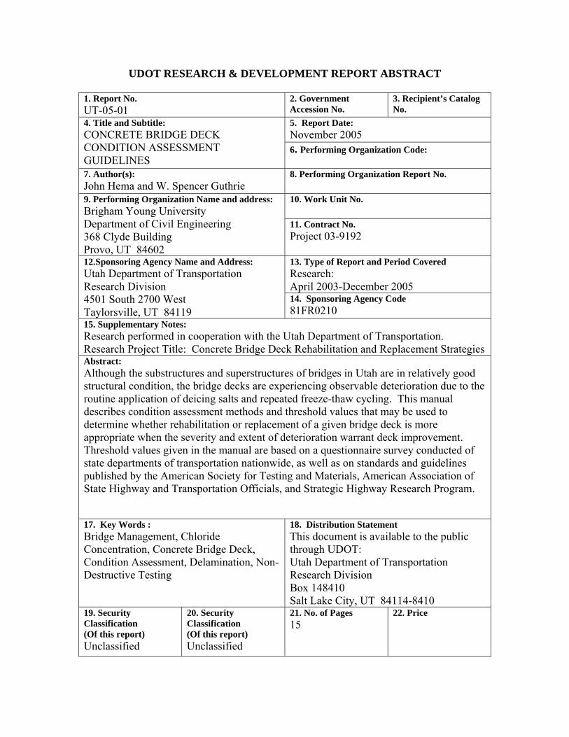
15. Supplementary Notes: Research performed in cooperation with the Utah Department of Transportation. Research Project Title: Concrete Bridge Deck Rehabilitation and Replacement Strategies Abstract: Although the substructures and superstructures of bridges in Utah are in relatively good structural condition, the bridge decks are experiencing observable deterioration due to the routine application of deicing salts and repeated freeze-thaw cycling. This manual describes condition assessment methods and threshold values that may be used to determine whether rehabilitation or replacement of a given bridge deck is more appropriate when the severity and extent of deterioration warrant deck improvement. Threshold values given in the manual are based on a questionnaire survey conducted of state departments of transportation nationwide, as well as on standards and guidelines published by the American Society for Testing and Materials, American Association of State Highway and Transportation Officials, and Strategic Highway Research Program.
17. Key Words : Bridge Management, Chloride Concentration, Concrete Bridge Deck, Condition Assessment, Delamination, Non-Destructive Testing
18. Distribution Statement This document is available to the public through UDOT: Utah Department of Transportation Research Division Box 148410 Salt Lake City, UT 84114-8410
19. Security Classification (Of this report) Unclassified
20. Security Classification (Of this report) Unclassified
21. No. of Pages 15
22. Price

THIS PAGE LEFT BLANK INTENTIONALLY
INTRODUCTION
The aging and deterioration of bridges in Utah mandates increasingly cost-effective strategies
for bridge maintenance, rehabilitation, and replacement (MR&R). The Utah Department of
Transportation (UDOT) is responsible for 1,700 bridges throughout the state, of which 46
percent are older than 30 years. Although the substructures and superstructures of bridges in
Utah are in relatively good structural condition, the bridge decks are experiencing observable
deterioration due to the routine application of deicing salts, repeated freeze-thaw cycles, and
other damaging effects. Therefore, the purpose of this manual is to provide guidance about
when a bridge deck should be rehabilitated or replaced.
Ultimately, development of a decision-making protocol that utilizes bridge deck
condition assessment information in combination with life-cycle costs is especially
important, since the costs associated with replacing every bridge deck in Utah are extremely
high. Identification of typical damage mechanisms and test methods for determining the
extent of damage sustained by concrete bridge decks are therefore important elements of this
manual. In particular, the utility of non-destructive testing to accurately and rapidly assess
bridge deck condition is emphasized. This manual describes viable condition assessment
methods and threshold values that UDOT may use to determine whether rehabilitation or
replacement of a given bridge deck is more appropriate when the severity and extent of
deterioration warrant deck improvement. Threshold values given in this manual are based on
a questionnaire survey conducted of state departments of transportations (DOTs) nationwide
(1), as well as on standards and guidelines published by the American Society of Testing and
Materials (ASTM), the American Association of State Highway and Transportation Officials
(AASHTO), and the Strategic Highway Research Program (SHRP).
CONDITION ASSESSMENT METHODS
Table 1 provides a summary of condition assessment methods appropriate for specific deck
distress types. A preliminary plan of action can be formulated by identifying the types of
bridge distresses to be investigated and then selecting the condition assessment methods that
are appropriate for measuring the severity and mapping the extent of deck deterioration.
Once condition assessment methods are selected from Table 1, ASTM, AASHTO, and SHRP
1

standards corresponding to each condition assessment method can be identified from Table 2.
The title of each ASTM, AASHTO, and SHRP standard is listed in Table 3.
TABLE 1 Condition Assessment Methods for Specific Deck Distresses
Distresses Condition Assessment Methods Air Pockets and Chain Dragging, Coring, Ground Penetrating Radar, Honeycombing Hammer Sounding, Impact-Echo, Ultrasonics,
Visual Inspection
Alkali-Silica Reaction Coring, Petrographic Analysis, Visual Inspection
Carbonation Coring, Penetration Dyes, Petrographic Analysis
Chloride-Induced Corrosion Chloride Concentration Testing, Coring, Half-Cell Potential, Rapid Chloride Permeability, Resistivity
Cracking Impact-Echo, Penetration Dyes, Ultrasonics, Visual Inspection
Delamination Chain Dragging, Coring, Ground Penetrating Radar, Hammer Sounding, Impact-Echo, Infrared Thermography, Ultrasonics
Polishing Skid Resistance Testing
Popouts Visual Inspection
Potholing Visual Inspection
Scaling Visual Inspection
Spalling Visual Inspection
Sulfate Attack Coring, Petrographic Analysis
2
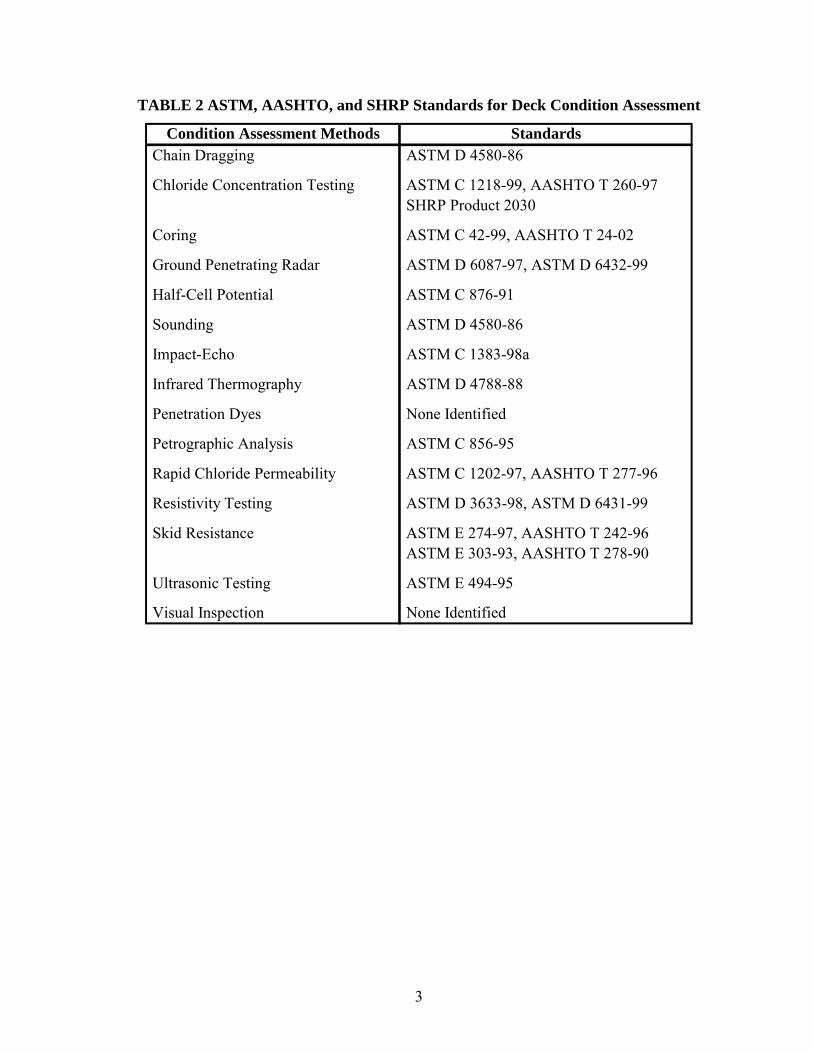
TABLE 2 ASTM, AASHTO, and SHRP Standards for Deck Condition Assessment
Condition Assessment Methods Standards Chain Dragging ASTM D 4580-86
Chloride Concentration Testing ASTM C 1218-99, AASHTO T 260-97 SHRP Product 2030
Coring ASTM C 42-99, AASHTO T 24-02
Ground Penetrating Radar ASTM D 6087-97, ASTM D 6432-99
Half-Cell Potential ASTM C 876-91
Sounding ASTM D 4580-86
Impact-Echo ASTM C 1383-98a
Infrared Thermography ASTM D 4788-88
Penetration Dyes None Identified
Petrographic Analysis ASTM C 856-95
Rapid Chloride Permeability ASTM C 1202-97, AASHTO T 277-96
Resistivity Testing ASTM D 3633-98, ASTM D 6431-99
Skid Resistance ASTM E 274-97, AASHTO T 242-96 ASTM E 303-93, AASHTO T 278-90
Ultrasonic Testing ASTM E 494-95
Visual Inspection None Identified
3
TABLE 3 Titles of ASTM, AASHTO, and SHRP Standards
Standards Titles ASTM C 42-99 Standard Test Method for Obtaining and Testing Drilled Cores and Sawed Beams of Concrete ASTM C 856-95 Standard Practice for Petrographic Examination of Hardened Concrete ASTM C 876-91 Standard Test Method for Half-Cell Potentials of Uncoated Reinforcing Steel in Concrete ASTM C 1202-97 Standard Test Method for Electrical Indication of Concrete's Ability to Resist Chloride Ion Penetration ASTM C 1218-99 Standard Test Method for Water-Soluble Chloride in Mortar and Concrete ASTM C 1383-98a Standard Test Method for Measuring the P-Wave Speed and the Thickness of Concrete Plates
Using the Impact-Echo Method ASTM D 3633-98 Standard Test Method for Electrical Resistivity of Membrane-Pavement Systems ASTM D 4580-86 Standard Practice for Measuring Delaminations in Concrete Bridge Decks by Sounding ASTM D 4788-88 Standard Test Method for Detecting Delaminations in Bridge Decks Using Infrared Thermography ASTM D 6087-97 Standard Test Method for Evaluating Asphalt-Covered Concrete Bridge Decks
Using Ground Penetrating Radar ASTM D 6431-99 Standard Guide for Using the Direct Current Resistivity Method for Subsurface Investigation ASTM D 6432-99 Standard Guide for Using the Surface Ground Penetrating Radar Method for Subsurface Investigation ASTM E 274-97 Standard Test Method for Skid Resistance of Paved Surfaces Using a Full-Scale Tire ASTM E 303-93 Standard Test Method for Measuring Surface Frictional Properties Using the British Pendulum Tester ASTM E 494-95 Standard Practice for Measuring Ultrasonic Velocity in Materials
AASHTO T 24-02 Obtaining and Testing Drilled Cores and Sawed Beams of Concrete AASHTO T 242-96 Frictional Properties of Paved Surfaces Using a Full-Scale Tire AASHTO T 260-97 Sampling and Testing for Chloride Ion in Concrete and Concrete Raw Materials AASHTO T 277-96 Electrical Indication of Concrete's Ability to Resist Chloride Ion Penetration AASHTO T 278-90 Surface Frictional Properties Using the British Pendulum Tester
SHRP Product 2030 Standard Test Method for Chloride Content in Concrete
4

THIS PAGE LEFT BLANK INTENTIONALLY
DATA EVALUATION
Both technical and economic factors influence the decision to rehabilitate or replace a bridge
deck. Project-level information is obtained from condition assessment surveys to determine
the overall condition of a bridge deck. Typically, this information includes measurements
associated with specific distresses and deterioration mechanisms. The information is then
analyzed to determine the types of rehabilitation methods that should be employed to extend
the service life of the bridge deck or to determine if a full-deck replacement is required.
The decision to rehabilitate or replace a bridge deck typically requires an economics
analysis for identifying the approach that will minimize the life-cycle cost of a bridge deck.
An economics analysis determines whether the costs for rehabilitation are more economical
over a given period of time than a full-deck replacement. However, bridge decks that exhibit
significant deterioration may not require an economics analysis; condition assessment alone
may be sufficient to eliminate rehabilitation as a viable option. In these cases, deterioration
would be so severe that the cost of a full-deck replacement would be unmistakably less
expensive than rehabilitative measures. Nonetheless, the use of economic analyses is usually
vital for bridge deck management and must be used in combination with technical factors to
provide optimal solutions in managing individual bridge decks.
Although the value of correct economics analyses cannot be over-emphasized, this
manual focuses strictly on providing technical information concerning threshold values for
several condition assessment methods and parameters; the mechanics of economics analyses
are not addressed. Condition assessment methods and parameters available for evaluating
existing damage and predicting the occurrence of future damage are presented. These
specifically include chloride concentration, cracking, delamination, half-cell potential,
popouts, potholes, rapid chloride permeability, resistivity, spalling, skid number, and
ultrasonic velocity. To the extent possible, threshold values associated with both the severity
of the distress and the percentage of the deck that is affected are discussed in the following
sections.
Chloride Concentration
In condition assessments of chloride-damaged bridge decks, chloride concentrations in the
vicinity of the top mat of reinforcement generally govern the decision to rehabilitate or
replace the deck. In general, state DOTs require action when chloride concentrations exceed
a threshold of 2.0 lbs/yd3 of concrete (1). The North Carolina DOT suggested in the DOT
survey that a full-deck replacement may be required if this threshold level is exceeded on
more than 30 percent of the deck area (1). While chloride concentration testing provides a
valuable assessment of the condition of concrete, the test cannot stand alone as a means for
determining an appropriate deck improvement strategy. Chloride concentration testing
should be used in conjunction with other condition assessment methods to determine whether
a bridge deck should be rehabilitated or replaced. For example, if not accompanied by
cracking, delaminations, or other deteriorative elements, corrosion may not be occurring even
though chloride concentrations may be high.
Cracking
A crack is defined as a break without a complete separation of parts. In bridge decks, cracks
are the precursors to more significant problems since they allow for the infiltration of
harmful chemicals and substances. The severity of deterioration caused by cracking is based
on crack width, crack density, and precipitation of solids in the cracks (1). In general, the
survey respondents indicated that action should be taken to correct crack deterioration when
crack thickness exceeds 0.0625 in. (1/16 in.) with moderate crack density, the extent of
cracking is greater than 30 percent of the total deck area, or efflorescence is evident in the
vicinity of the crack (1). The New Jersey DOT specified that any crack that is thought to be
more than a shrinkage crack should be sealed (1).
Delamination
Corrosion-related delaminations form when the upper layer of reinforcing steel rusts, thereby
breaking the bond between the steel and the surrounding concrete. Debonding of the
concrete from the reinforcing steel reduces the structural capacity of the deck and allows for
harmful substances to migrate at accelerated rates towards the reinforcement. In general,
DOTs indicated that the extent of concrete delamination that requires action is between 5 and
20 percent of the total deck area. The New Jersey DOT requires action when 40 percent or
more of the deck area exhibits spalling or delaminations (1). The Wyoming DOT indicated
that patching is utilized when up to 5 percent of the deck area is delaminated; however,
6
delaminations exceeding 5 percent of the deck area require patching with silica fume
concrete followed by a bridge deck overlay (1).
The Washington DOT suggested that delaminations should be repaired and a 1.5-in.
modified concrete overlay should be applied when delaminations exceed more than 2 percent
of the total deck area (1). This criterion for repair is deliberately conservative since a year or
more is often required to secure funding for the repair project; the Washington DOT
indicated that during the waiting period the extent of delaminations typically increases to 5
percent or more.
The AASHTO Guide for Commonly Recognized (CoRe) Structural Elements gives
guidelines for delaminations exhibited on bare concrete decks with uncoated reinforcement,
with coated reinforcement, or with a cathodic system (2). Delaminations affecting less than
10 percent of the deck area may be repaired, or a protective system may be installed to mask
the damage. Delaminations affecting 10 to 50 percent of the deck area should be repaired,
and an optional protective system may be applied to the entire deck surface. If delaminations
are present on more than 50 percent of the deck area, the deteriorated areas should be
repaired, and a protective system should be installed across the entire deck; otherwise, a full-
deck replacement is required.
The AASHTO Guide for Commonly Recognized (CoRe) Structural Elements gives
additional guidelines for delaminations exhibited on concrete decks with thin or rigid
overlays (2). Delaminations affecting less than 25 percent of the deck area should be
repaired; however, if delaminations affect more than 25 percent of the deck area, the existing
overlay should be removed, and the repairs should be followed with installation of a new
protective overlay.
Half-Cell Potential
The severity of steel corrosion in concrete can be determined by measuring the electrical
half-cell potential of uncoated reinforcing steel (3). ASTM C 876 (Standard Test Method for
Half-Cell Potentials of Uncoated Reinforcing Steel in Concrete) specifies that potential
measurements more negative than −0.35 V using a copper-copper sulfate electrode (CSE)
indicate a probability greater than 90 percent that corrosion is occurring. Potential
7
measurements more positive than −0.20 V CSE indicate a probability greater than 90 percent
that corrosion is not occurring in that area. Potential measurements between −0.20 and
−0.35 V CSE indicate that corrosion in that area is uncertain. However, studies have been
conducted that conflict with these threshold values designated in ASTM C 876 (4, 5).
Therefore, published threshold values in ASTM C 876 should only be used as guidelines
since a precise delineation of steel from a passive to an active state cannot be made to
encompass all bridges.
Nonetheless, the threshold values reported in the DOT surveys are consistent with
ASTM C 876. The Connecticut DOT specified that action should be taken when more than
40 percent of the potential measurements are more negative than −0.35 V CSE (1). The
Rhode Island DOT confirmed that action should be taken when values are below −0.35 V
CSE, provided that other forms of deterioration are present (1).
The Oklahoma DOT provided several threshold values for rehabilitation and
replacement (1). A full-depth replacement of the bridge deck is required when potential
measurements are more negative than −0.40 V CSE. Potential measurements between −0.35
and −0.40 V CSE require reparations to delaminations, spalls, and cracks below the top mat
of reinforcement. Repair of the top mat of reinforcement is required when potential
measurements are between −0.25 and −0.35 V CSE.
Popouts
Popouts are conically shaped depressions that are associated with the removal or rupturing of
aggregate particles near the concrete surface. DOTs indicated in the questionnaire survey
that popouts should be repaired when deterioration impacts the traveling public; such impacts
may appear in the form of roughness of the roadway surface or vehicle damage caused by
popouts being projected into the air (1).
Potholes
Potholes are bowl-shaped holes of various sizes with a minimum width of 6 in. They
constitute a dangerous safety hazard that can produce substantial damage to vehicles, force
drivers to veer suddenly in traffic, or even cause drivers to lose control of their vehicles after
8
contact. State DOTs reported taking remedial action when the deck area exhibits any sign of
potholes.
The AASHTO Guide for Commonly Recognized (CoRe) Structural Elements gives
guidelines for repairing potholes exhibited on concrete decks with or without asphalt
concrete overlays (2). Potholes occurring on less than 10 percent of the total deck area
should be repaired. If potholes affect 10 to 50 percent of the deck area, the deteriorated areas
should be repaired, and a new protective overlay should be applied to the entire deck surface
upon removal of an existing overlay, if present. Potholes exhibited on more than 50 percent
of the deck area may also be repaired in this manner but may also warrant a full-deck
replacement instead.
Rapid Chloride Permeability
Low-permeability concrete generally possesses high strength and is resistant to the
infiltration of water and chlorides. Conversely, extremely porous concrete allows water,
salts, and oxygen to more easily reach the reinforcing steel, which accelerates corrosion of
the reinforcement. By measuring the chloride permeability of concrete, durability problems
can be detected early so that timely and cost-effective protective measures can be
implemented before the occurrence of significant steel corrosion or concrete deterioration.
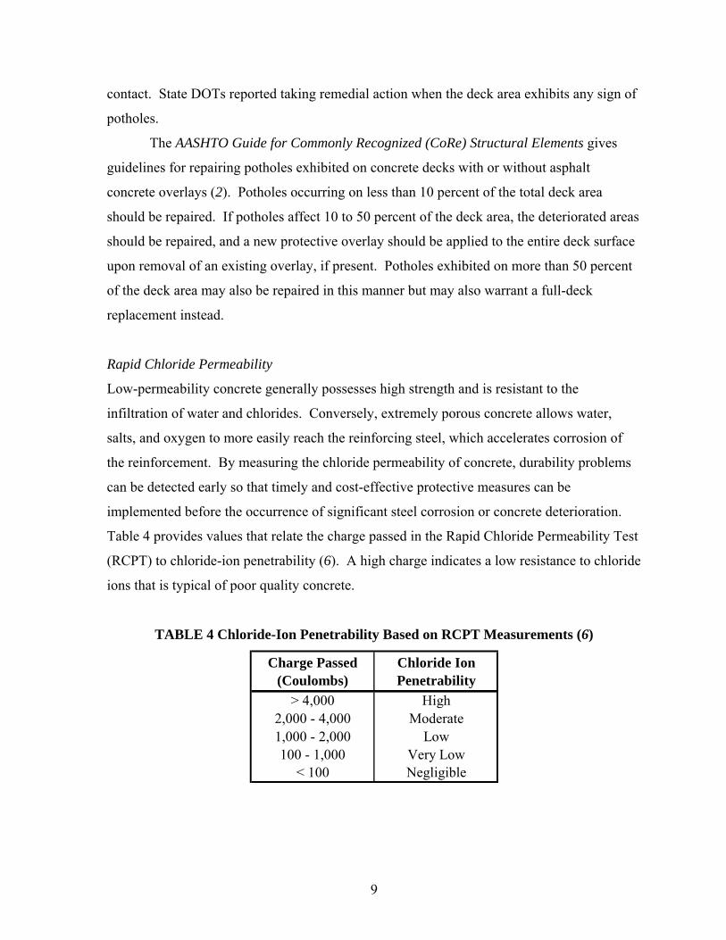
Table 4 provides values that relate the charge passed in the Rapid Chloride Permeability Test
(RCPT) to chloride-ion penetrability (6). A high charge indicates a low resistance to chloride
ions that is typical of poor quality concrete.
TABLE 4 Chloride-Ion Penetrability Based on RCPT Measurements (6)
Charge Passed (Coulombs)
Chloride Ion Penetrability
> 4,000 High2,000 - 4,000 Moderate1,000 - 2,000 Low100 - 1,000 Very Low
< 100 Negligible
9
Resistivity
Resistivity testing is a method that uses electrical resistance to evaluate the quality of
reinforced concrete. The technique measures the likelihood of the reinforcing steel to
corrode, rather than the amount of distress that has already occurred due to corrosion (7).
Tests have been performed to investigate the resistivity of concrete in various conditions.
Moist concrete typically displays a resistivity of 10 Kohm-cm, while oven-dried concrete
exhibits a resistivity of 10 Mohm-cm (7). Data from a study in Great Britain indicate that
corrosion is almost certain to occur when resistivity measurements are less than 5 Kohm-cm
(7). When resistivity measurements are between 5 and 12 Kohm-cm, corrosion is probable
(7). The research results suggest that corrosion is unlikely to occur when resistivity
measurements are in excess of 12 Kohm-cm (7). The instruction manual for the James RM-
8000 resistivity meter provides a table that correlates resistivity measurements to possible
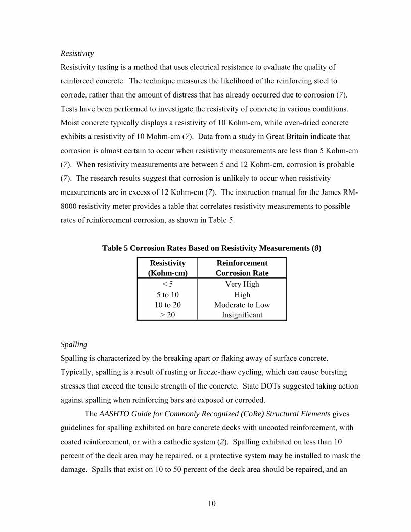
rates of reinforcement corrosion, as shown in Table 5.
Table 5 Corrosion Rates Based on Resistivity Measurements (8)
< 5 Very High5 to 10 High
10 to 20 Moderate to Low> 20 Insignificant
Resistivity (Kohm-cm)
Reinforcement Corrosion Rate
Spalling
Spalling is characterized by the breaking apart or flaking away of surface concrete.
Typically, spalling is a result of rusting or freeze-thaw cycling, which can cause bursting
stresses that exceed the tensile strength of the concrete. State DOTs suggested taking action
against spalling when reinforcing bars are exposed or corroded.
The AASHTO Guide for Commonly Recognized (CoRe) Structural Elements gives
guidelines for spalling exhibited on bare concrete decks with uncoated reinforcement, with
coated reinforcement, or with a cathodic system (2). Spalling exhibited on less than 10
percent of the deck area may be repaired, or a protective system may be installed to mask the
damage. Spalls that exist on 10 to 50 percent of the deck area should be repaired, and an
10
optional protective system may be applied to the entire deck surface. Spalling exhibited on
more than 50 percent of the deck area requires repair and installation of a protective system;
otherwise, a full-deck replacement is required.
The AASHTO Guide for Commonly Recognized (CoRe) Structural Elements gives
additional guidelines for spalling exhibited on concrete decks with a thin or rigid overlay (2).
Spalling exhibited on less than 25 percent of the deck area should be repaired. However,
when spalling exists on more than 25 percent of the deck area, simple repairs may be
inappropriate; instead, the existing overlay may need to be removed and replaced with a new
protective overlay.
Skid Number
The skid number reflects the surface texture of a bridge deck. State DOTs reported taking
corrective measures for skid resistance numbers below 30 to 35 when measured according to
ASTM E 274 (Standard Test Method for Skid Resistance of Paved Surfaces Using a Full-
Scale Tire).
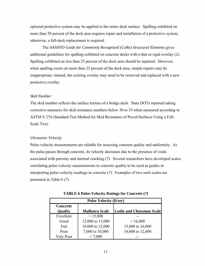
Ultrasonic Velocity
Pulse-velocity measurements are reliable for assessing concrete quality and uniformity. As
the pulse passes through concrete, its velocity decreases due to the presence of voids
associated with porosity and internal cracking (7). Several researchers have developed scales
correlating pulse-velocity measurements to concrete quality to be used as guides in
interpreting pulse-velocity readings in concrete (7). Examples of two such scales are
presented in Table 6 (7).
TABLE 6 Pulse-Velocity Ratings for Concrete (7)
Excellent > 15,000 --Good 12,000 to 15,000 > 16,000Fair 10,000 to 12,000 13,000 to 16,000Poor 7,000 to 10,000 10,000 to 12,000
Very Poor < 7,000 --
Pulse Velocity (ft/sec)Concrete Quality Malhotra Scale Leslie and Cheesman Scale
11
THIS PAGE LEFT BLANK INTENTIONALLY
CONCLUSION
This manual describes viable condition assessment methods and threshold values that UDOT
may use to determine whether rehabilitation or replacement of a given bridge deck is more
appropriate when the severity and extent of deterioration warrant deck improvement.
Condition assessment methods and parameters for evaluating existing damage and predicting
the occurrence of future damage are presented. Corresponding threshold values are based on
data collected through a questionnaire survey conducted of state DOTs nationwide, as well as
on standards and guidelines published by ASTM, AASHTO, and SHRP. This information
should be useful to bridge engineers responsible for rating concrete bridge deck condition
and programming MR&R strategies at primarily the project level of bridge management.
While in some cases deck condition information may directly dictate whether or not the deck
should be replaced, the value of economics analyses to compute life-cycle costs cannot be
over-emphasized. The results of economic analyses must be considered in combination with
technical data to provide optimal management solutions for individual bridge decks.
ACKNOWLEDGMENTS
The authors wish to acknowledge Mr. Daniel Hsiao of UDOT for directing this project.
Also, appreciation is given to the individuals who participated in the round table discussion
held at the beginning of this research effort, including Mr. Bruce Collins of Restruction
Corporation, Mr. Jerry Hall of Geneva Rock, Mr. Tod Wadsworth of Ralph Wadsworth
Construction, Mr. David Nazare of UDOT, and Mr. Bill Lawrence of UDOT.
13
REFERENCES
1. Hema J., W. S. Guthrie, and F. Fonseca. Concrete Bridge Deck Condition Assessment
and Improvement Strategies. Report UT-04-16. Department of Civil and Environmental
Engineering, Brigham Young University, Provo, UT, 2004.
2. AASHTO Guide for Commonly Recognized (CoRe) Structural Elements. Subcommittee
on Bridge and Structures of the Standing Committee of Highways, American Association of
State Highway and Transportation Officials, Washington, D.C., 1997.
3. Standard Test Method for Half-Cell Potentials of Uncoated Reinforcing Steel in Concrete.
ASTM C 876-99, American Society of Testing and Materials, West Conshohocken, PA,
1999, pp. 9-14.
4. Stratfull, R. F. Half-Cell Potentials and the Corrosion of Steel in Concrete. In Highway
Research Record 433, HRB, National Research Council, Washington, D.C., 1973, pp. 12-21.
5. Elsener B. and H. Bohni. Potential Mapping and Corrosion of Steel in Concrete. In
ASTM Special Technical Publication No. 1065, Philadelphia, PA, 1990, pp. 143-156.
6. Standard Test Method for Electrical Indication of Concrete’s Ability to Resist Chloride
Ion Penetration. ASTM C 1202-97, American Society of Testing and Materials, West
Conshohocken, PA, 1999, pp. 646-651.
7. Manning, D. G. Detecting Defects and Deterioration in Highway Structures. In National
Cooperative Highway Research Program Synthesis of Highway Practice 118, TRB, National
Research Council, Washington, D.C., 1985.
8. RM-8000 Resistivity Meter Instruction Manual. James Instruments Inc., Chicago, IL,
2004.
14