Conceptual design study Kriegers Flak 090618 redused
42
© Vattenfall AB Conceptual Design Study Kriegers Flak Windforce 09, 18th june, 2009 Thomas Stalin, Vattenfall Wind Power AB
-
Upload
thomas-stalin -
Category
Documents
-
view
281 -
download
4
Transcript of Conceptual design study Kriegers Flak 090618 redused
© Vattenfall AB
Conceptual Design Study Kriegers Flak
Windforce 09, 18th june, 2009 Thomas Stalin, Vattenfall Wind Power AB
© Vattenfall AB 2
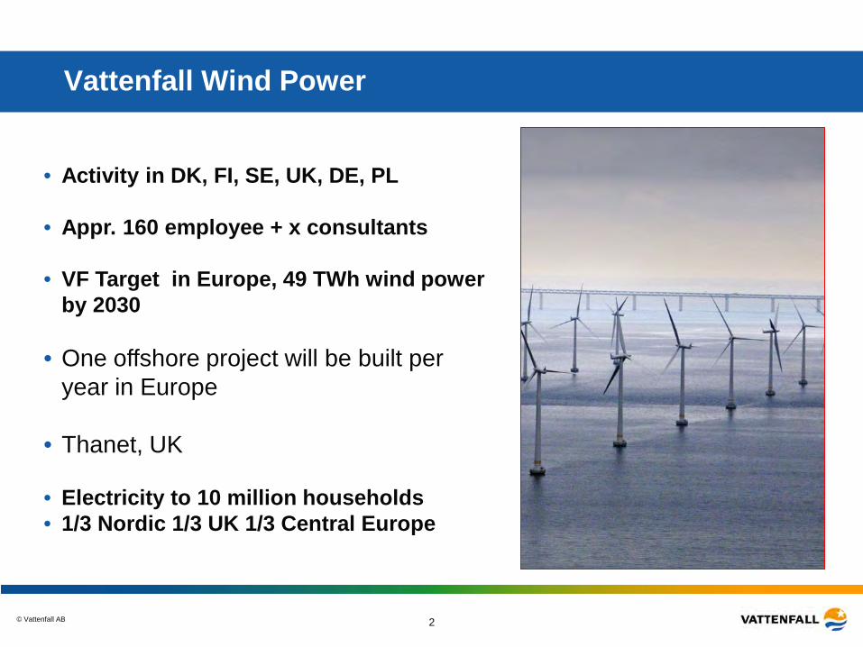
Vattenfall Wind Power
• Activity in DK, FI, SE, UK, DE, PL
• Appr. 160 employee + x consultants • VF Target in Europe, 49 TWh wind power
by 2030
• One offshore project will be built per year in Europe
• Thanet, UK
• Electricity to 10 million households • 1/3 Nordic 1/3 UK 1/3 Central Europe
© Vattenfall AB 3
Targets for Sweden
• Vattenfall share 8 TWh of 16 TWh to 2016 – 4 TWh onshore – 4 TWh offshore
• New political target 25 TWh to 2020 – Vattenfalls share even larger!!!!
• Focus in Sweden first be onshore in the forest • Offshore has high technical risk and high investment cost • Price for green certificates equal for onshore and offshore
• Vattenfall will first build offshore in the countries where we can
meet profitability, GB and DE
• When turbines have matured and total price for green electricity has increased we will build offshore in Sweden
– Political process • Kriegers flak is planned to be built in phases starting 2013
© Vattenfall AB 4 4
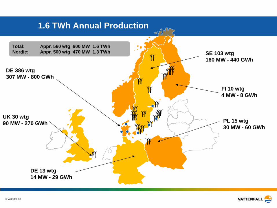
SE 103 wtg 160 MW - 440 GWh
FI 10 wtg 4 MW - 8 GWh
DE 386 wtg 307 MW - 800 GWh
UK 30 wtg 90 MW - 270 GWh
Total: Appr. 560 wtg 600 MW 1.6 TWh Nordic: Appr. 500 wtg 470 MW 1.3 TWh
1.6 TWh Annual Production
PL 15 wtg 30 MW - 60 GWh
DE 13 wtg 14 MW - 29 GWh
© Vattenfall AB 5
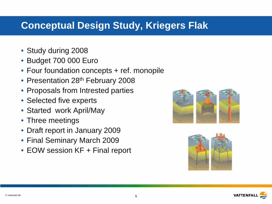
Conceptual Design Study, Kriegers Flak
• Study during 2008 • Budget 700 000 Euro • Four foundation concepts + ref. monopile • Presentation 28th February 2008 • Proposals from Intrested parties • Selected five experts • Started work April/May • Three meetings • Draft report in January 2009 • Final Seminary March 2009 • EOW session KF + Final report
© Vattenfall AB 6
Aim of Project
• Costefficient Foundations for 15 to 45 meter water deepths – Calculations and drawings – Installation method and specification of equipment – Including estimate of fabrication and installation cost
• Reduce the cost = Reduce the risk – Use the time to investigate the conditions – Find areas that needs further investigations
• Conceptual design for the tender process – Good base for estimate of volumes of material and labour – Detailed drawings and worked through concepts
• Establish contacts to Contractors well in advance of tender – Good knowledge of the project
• Transfer of knowledge to Vattenfall – Ability to make conceptual design and estimate cost
• Support the generall knowledge – Develop concepts for deeper waters
© Vattenfall AB 7
Prehistory
• Year 2003 to 2005 Project development focused on permits and not on implementations and long term ownership
– Millions on environmental investigation – Before permit => 100% risk to loose money invested in technical
problem solving – Long technical lead times when permit ready
=> Work in parallel • Project development without knowing final cost • No projects built on deep waters • STEM Call for Offshore Pilot Studies • Application in March April 2004 • In May 2005 project sold to Vattenfall
– Long term ownership • Funds approved by STEM 2005
© Vattenfall AB 8
Background
• Started Design Basis 2007 • Detailed geotechnical investigation 2007
– Geobore S, CPTs, Vibro core – Analyse first half 2008
• How to utilize time to reduce risk – While project starts 2013
• How to get lower prices for foundations – Better information for tendering phase – Several pre-engineered concepts – Contractors see possibilities and understand risk
• Optimal time schedule for tendering process – Adopt time to allow the best solution a chance to win
• Volunteer before tendering in order to get the things done in advance that should be done but normally first is done after the contract is signed
© Vattenfall AB 9
Consultants
• Ramböll and MTHojgaard – Jacket – Ref. Monopile
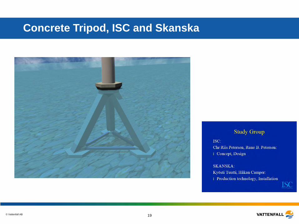
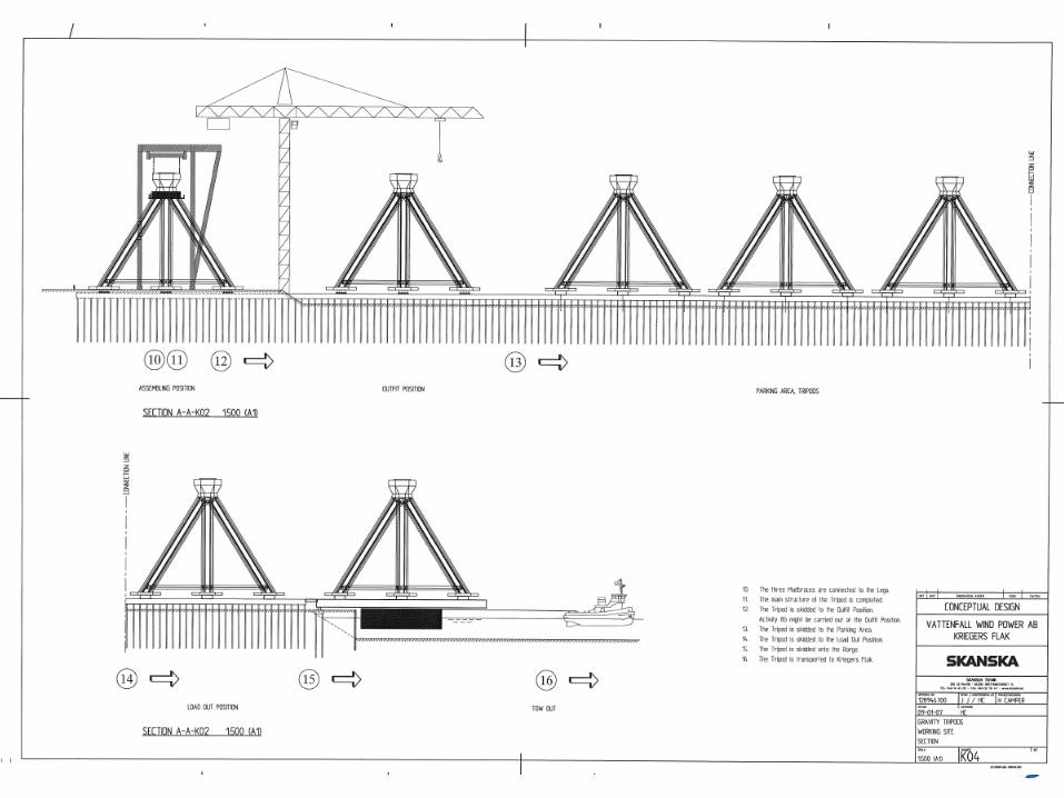
• ISC and Skanska – Concrete Tripod
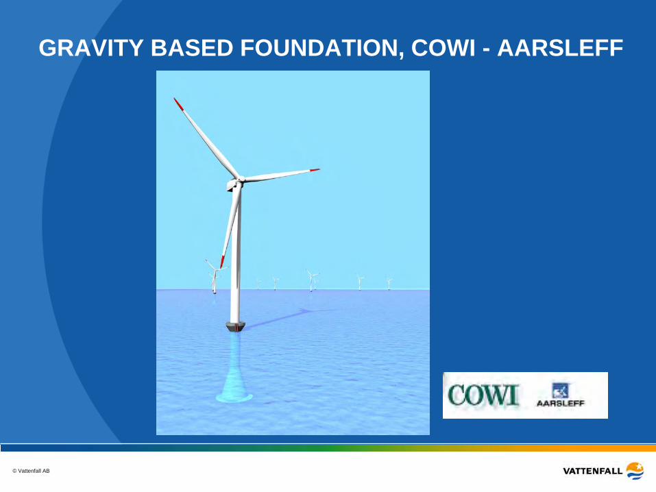
• COWI and Aahrsleff – Cone Gravity foundation
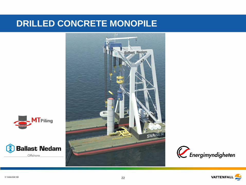
• Ballast Nedam and MTPiling – Drilled Concrete Monopile
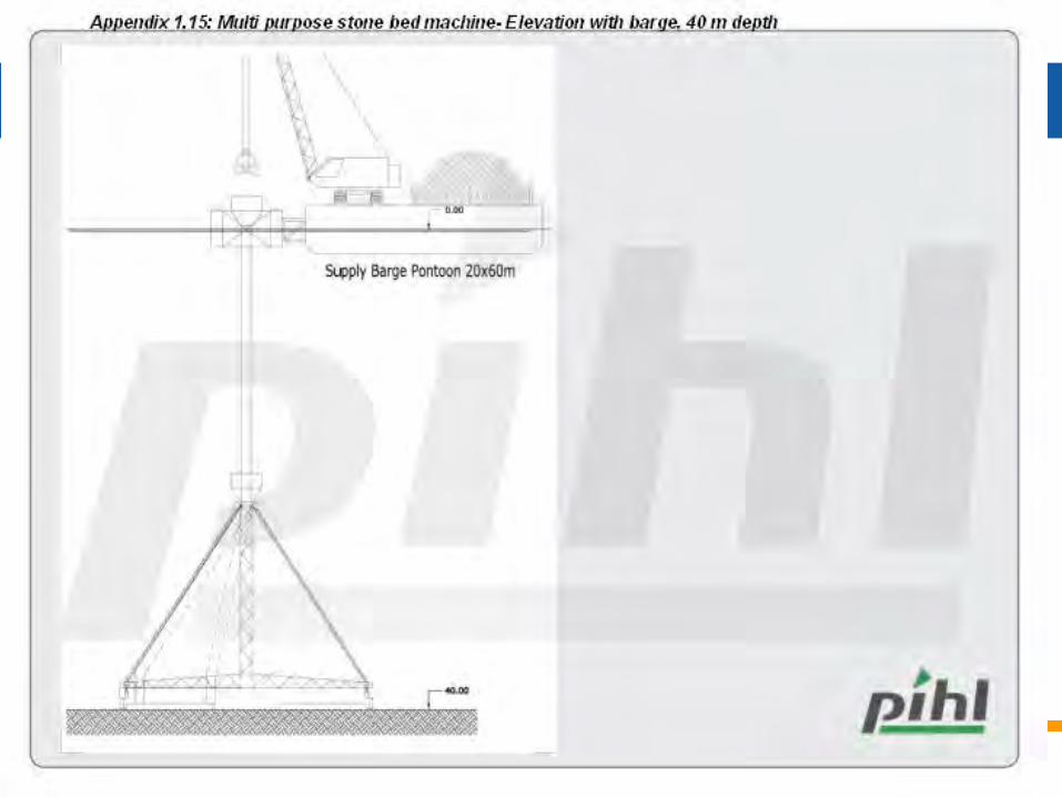
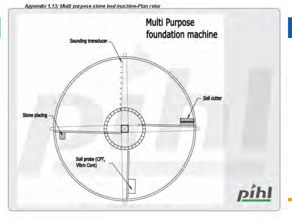
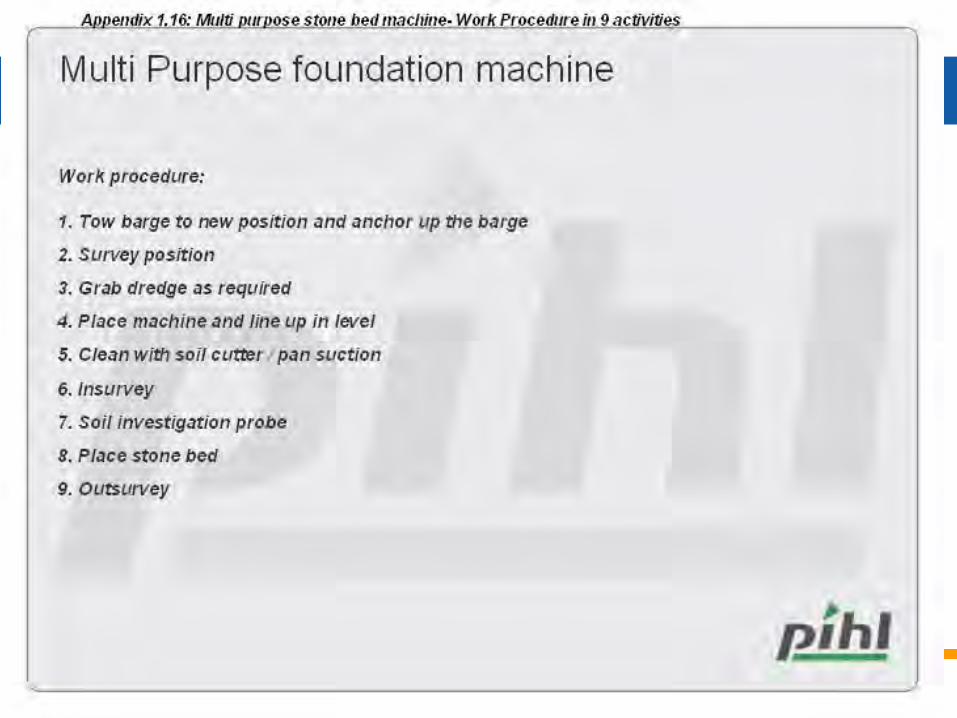
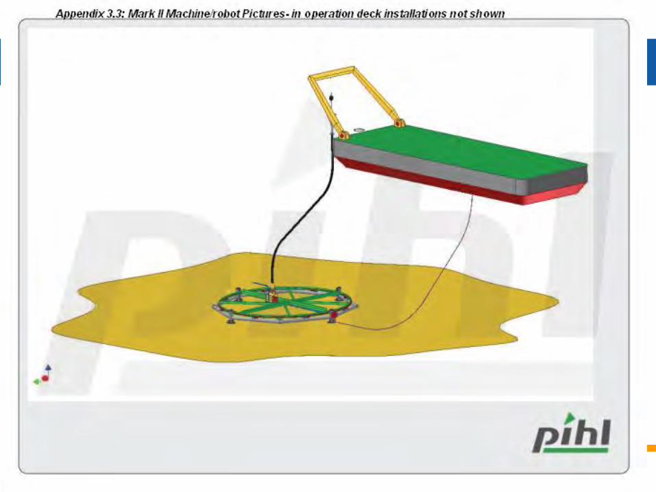
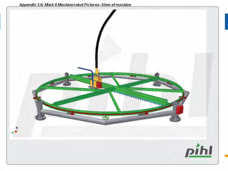
• Pihl – Automatic stone bed preparation robot
© Vattenfall AB 10
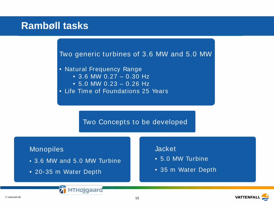
Rambøll tasks
Two generic turbines of 3.6 MW and 5.0 MW • Natural Frequency Range
• 3.6 MW 0.27 – 0.30 Hz • 5.0 MW 0.23 – 0.26 Hz
• Life Time of Foundations 25 Years
Monopiles • 3.6 MW and 5.0 MW Turbine
• 20-35 m Water Depth
Jacket • 5.0 MW Turbine
• 35 m Water Depth
Two Concepts to be developed
© Vattenfall AB 11
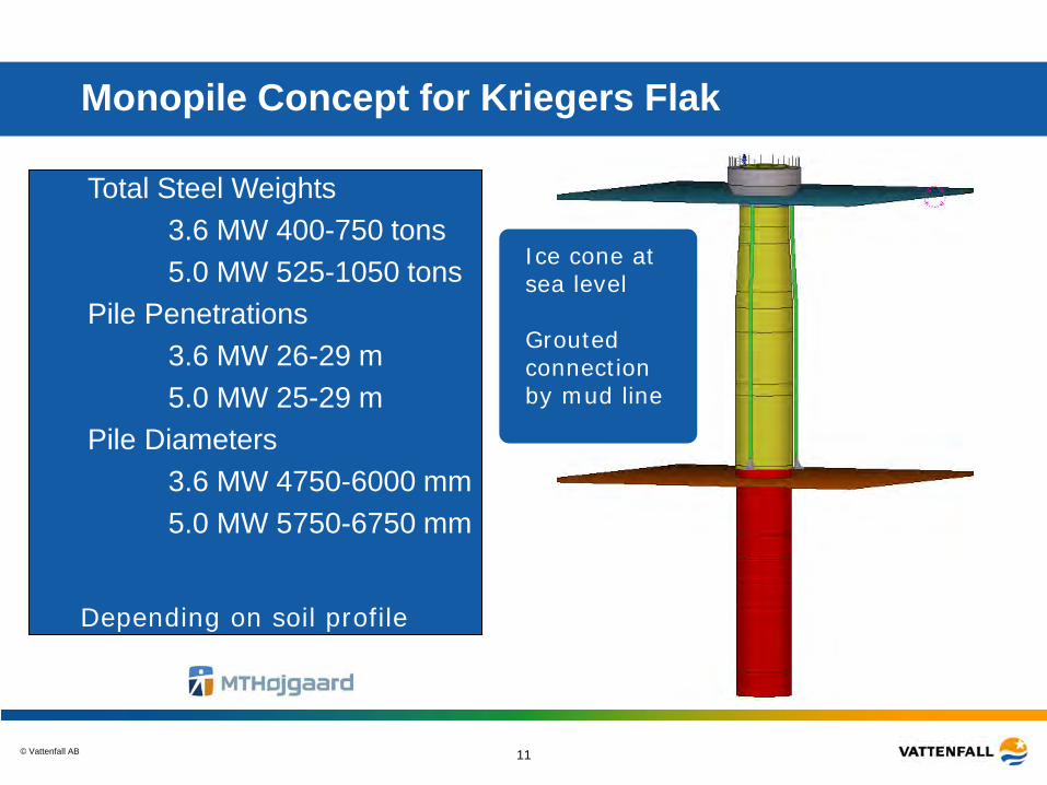
Monopile Concept for Kriegers Flak
Total Steel Weights • 3.6 MW 400-750 tons • 5.0 MW 525-1050 tons
Pile Penetrations • 3.6 MW 26-29 m • 5.0 MW 25-29 m
Pile Diameters • 3.6 MW 4750-6000 mm • 5.0 MW 5750-6750 mm
Ice cone at sea level Grouted connection by mud line
Depending on soil profile
© Vattenfall AB 12
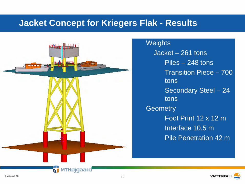
Jacket Concept for Kriegers Flak - Results
Weights – Jacket – 261 tons
• Piles – 248 tons • Transition Piece – 700
tons • Secondary Steel – 24
tons Geometry
• Foot Print 12 x 12 m • Interface 10.5 m • Pile Penetration 42 m
© Vattenfall AB
GRAVITY BASED FOUNDATION, COWI - AARSLEFF
© Vattenfall AB 27/03/2015
Gravity Based Foundation - Conceptual design 14
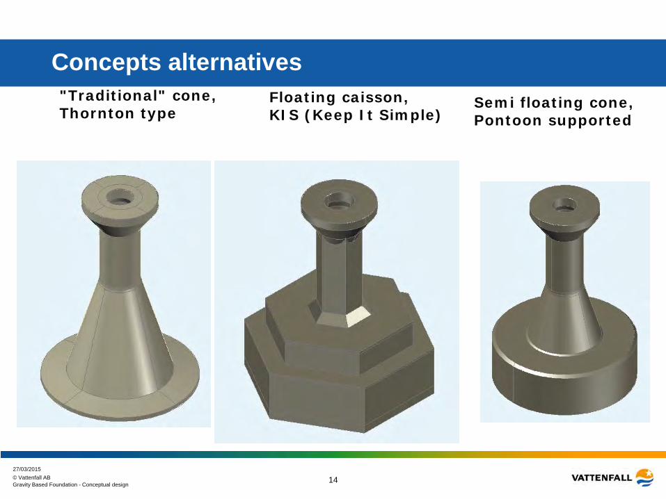
Concepts alternatives "Traditional" cone, Thornton type
Floating caisson, KIS (Keep It Simple)
Semi floating cone, Pontoon supported
© Vattenfall AB 27/03/2015
Gravity Based Foundation - Conceptual design 15
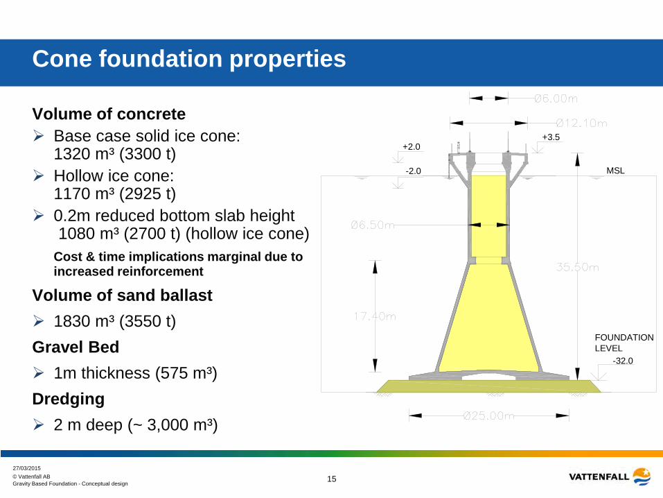
Cone foundation properties
Volume of concrete Base case solid ice cone:
1320 m³ (3300 t) Hollow ice cone:
1170 m³ (2925 t) 0.2m reduced bottom slab height
1080 m³ (2700 t) (hollow ice cone) Cost & time implications marginal due to
increased reinforcement
Volume of sand ballast 1830 m³ (3550 t) Gravel Bed 1m thickness (575 m³) Dredging 2 m deep (~ 3,000 m³)
-32.0
FOUNDATIONLEVEL
+2.0
-2.0
+3.5
MSL
© Vattenfall AB 16
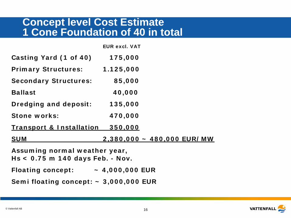
Concept level Cost Estimate 1 Cone Foundation of 40 in total
EUR excl. VAT
Casting Yard (1 of 40) 175,000
Primary Structures: 1.125,000
Secondary Structures: 85,000
Ballast 40,000
Dredging and deposit: 135,000
Stone works: 470,000
Transport & Installation 350,000
SUM 2,380,000 ~ 480,000 EUR/MW
Assuming normal weather year, Hs < 0.75 m 140 days Feb. - Nov.
Floating concept: ~ 4,000,000 EUR
Semi floating concept: ~ 3,000,000 EUR
© Vattenfall AB 17
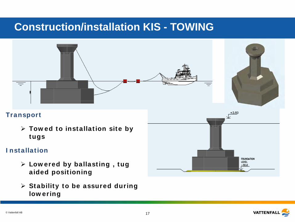
Construction/installation KIS - TOWING
Transport
Towed to installation site by tugs
Installation
Lowered by ballasting , tug aided positioning
Stability to be assured during lowering
© Vattenfall AB 18
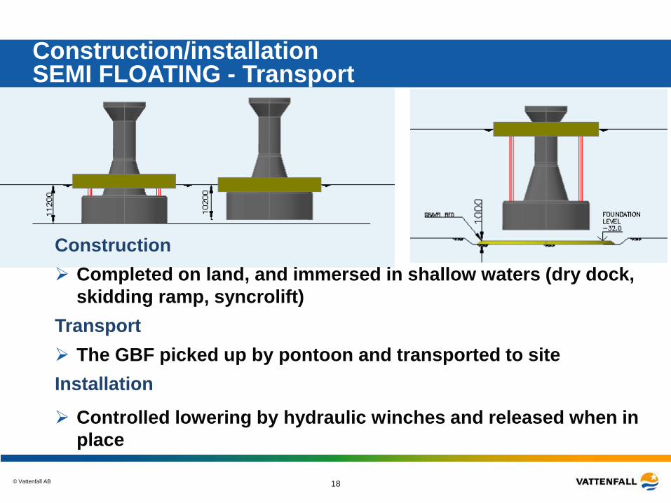
Construction/installation SEMI FLOATING - Transport
Construction Completed on land, and immersed in shallow waters (dry dock,
skidding ramp, syncrolift) Transport The GBF picked up by pontoon and transported to site Installation
Controlled lowering by hydraulic winches and released when in place
© Vattenfall AB 19
Concrete Tripod, ISC and Skanska
© Vattenfall AB 20
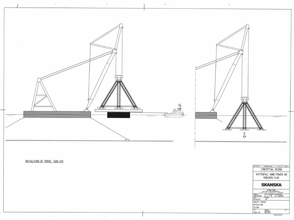
© Vattenfall AB 21
© Vattenfall AB 22
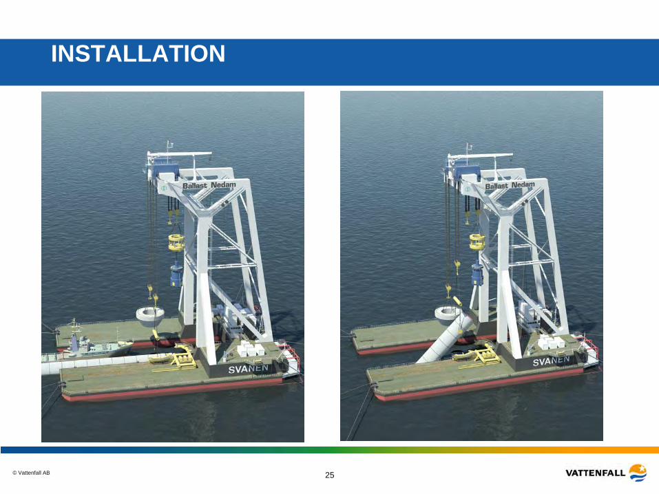
DRILLED CONCRETE MONOPILE
© Vattenfall AB 23
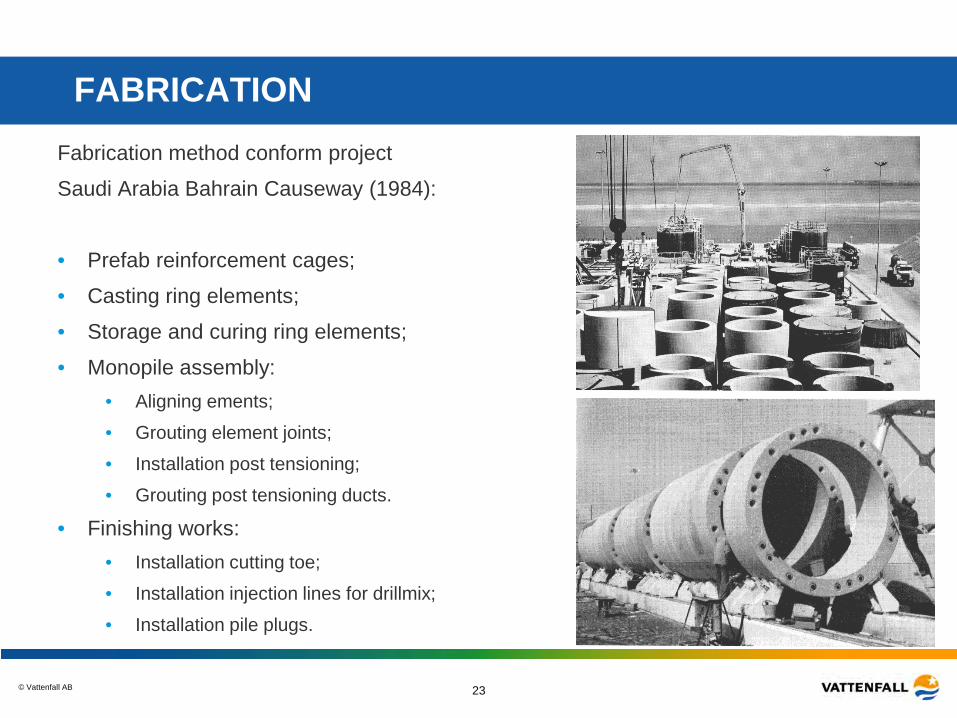
FABRICATION Fabrication method conform project
Saudi Arabia Bahrain Causeway (1984):
• Prefab reinforcement cages;
• Casting ring elements;
• Storage and curing ring elements;
• Monopile assembly: • Aligning ements;
• Grouting element joints;
• Installation post tensioning;
• Grouting post tensioning ducts.
• Finishing works: • Installation cutting toe;
• Installation injection lines for drillmix;
• Installation pile plugs.
© Vattenfall AB 24
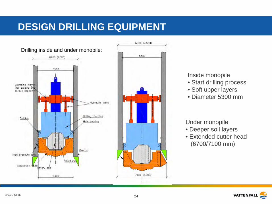
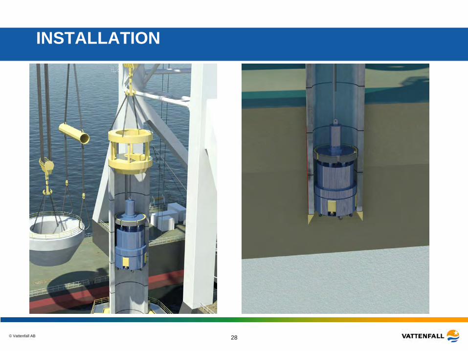
Drilling inside and under monopile:
Inside monopile • Start drilling process • Soft upper layers • Diameter 5300 mm
DESIGN DRILLING EQUIPMENT
Under monopile • Deeper soil layers • Extended cutter head (6700/7100 mm)
© Vattenfall AB 25
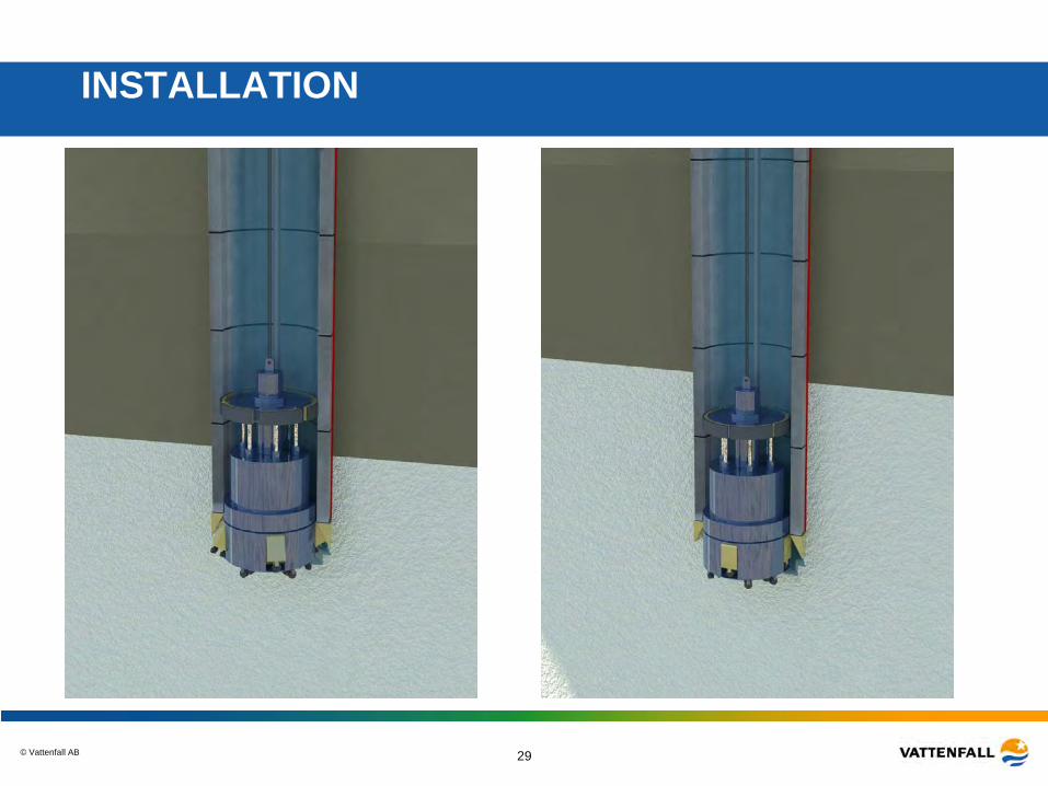
INSTALLATION
© Vattenfall AB 26
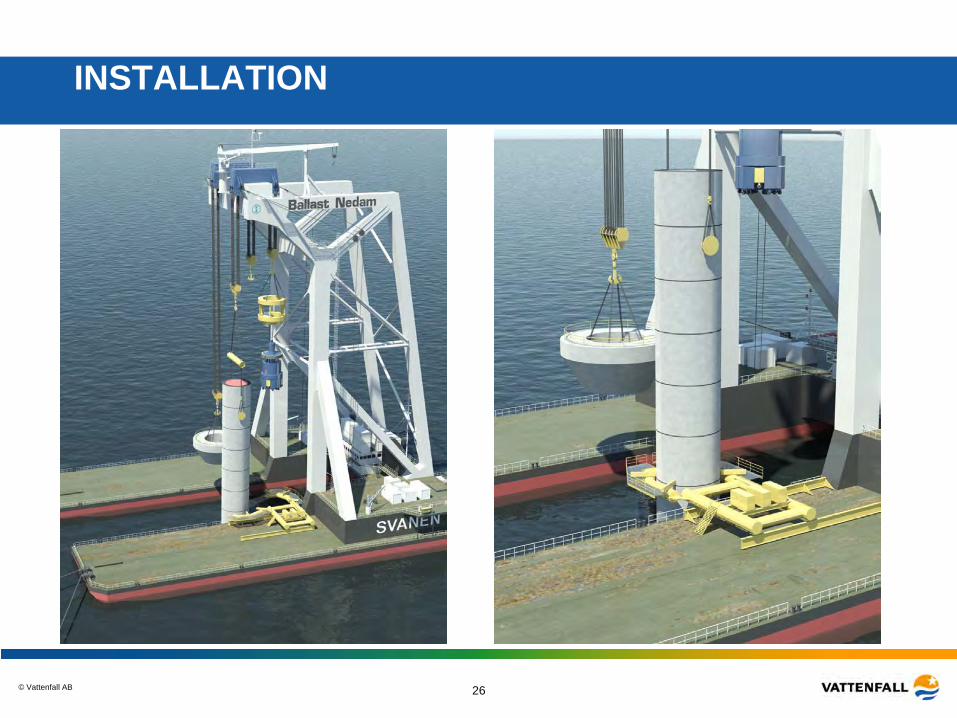
INSTALLATION
© Vattenfall AB 27
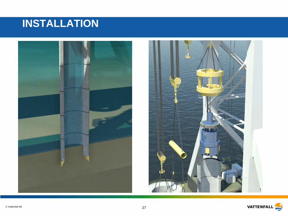
INSTALLATION
© Vattenfall AB 28
INSTALLATION
© Vattenfall AB 29
INSTALLATION
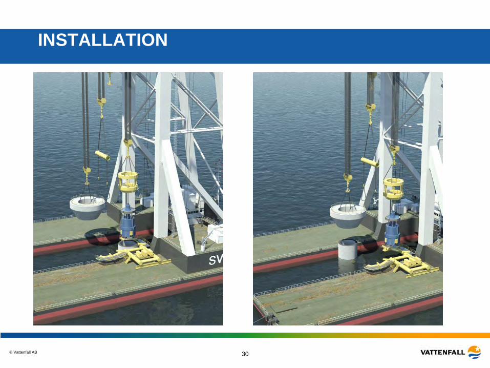
© Vattenfall AB 30
INSTALLATION
© Vattenfall AB 31
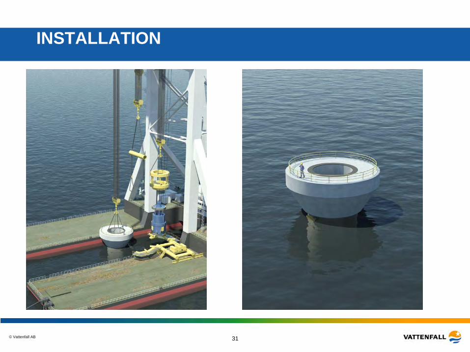
INSTALLATION
© Vattenfall AB 32
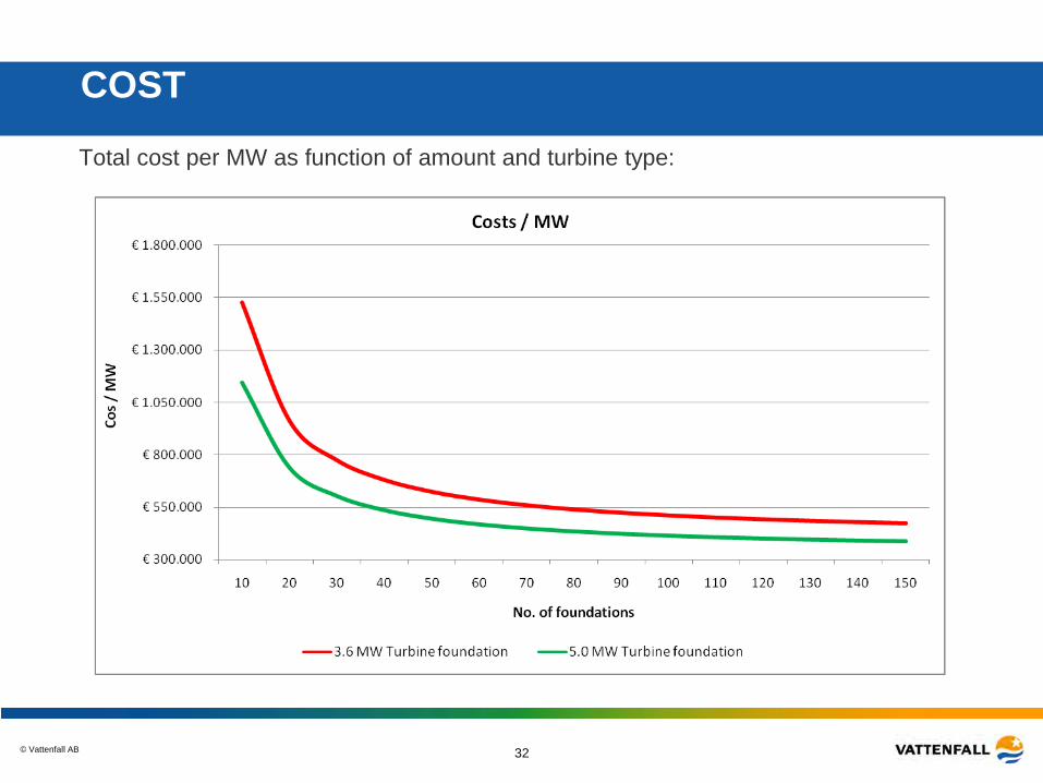
COST
Total cost per MW as function of amount and turbine type:
© Vattenfall AB 33
© Vattenfall AB 34
© Vattenfall AB 35
© Vattenfall AB 36
© Vattenfall AB 37
© Vattenfall AB 38
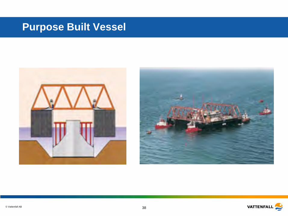
Purpose Built Vessel
© Vattenfall AB 39
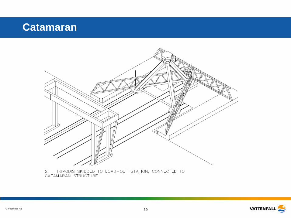
Catamaran
© Vattenfall AB 40
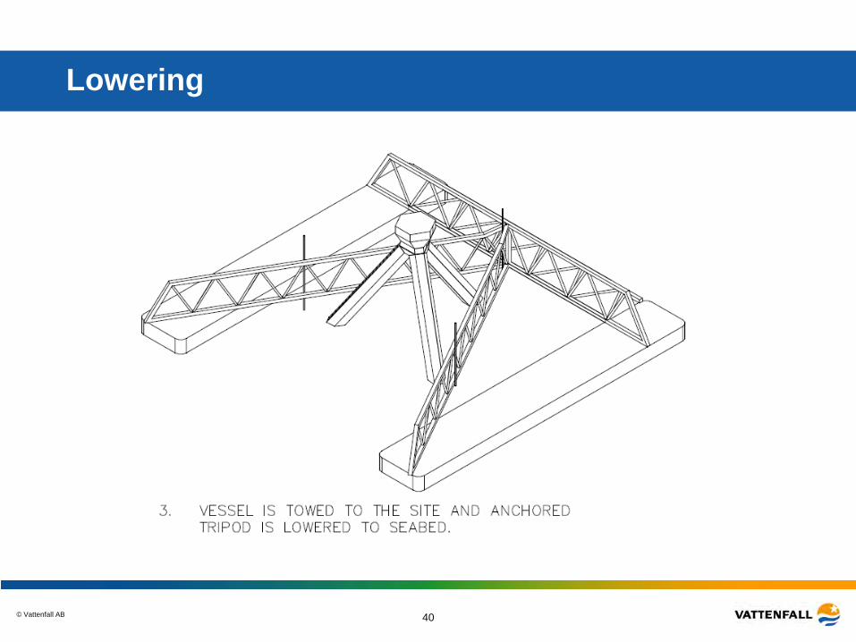
Lowering
© Vattenfall AB 41
Result
• Based on Geotechnical investigations and measurements on Wind and Waves we have developed a Design Basis that was used in the project
– First test of design basis • Individual experts developed the concepts with comments from the others
experts, team-work under competition, sharing of experience. Helge Gravesen was the project manager
• Worked out five foundation concepts and one seabed preparation robot • Managed to find some solutions in the range below 500 Euro/kW • For the coming Tender process we have a good material in form of the five
worked out Conceptual designs • Vattenfall gained knowledge on volumes, prices and time schedules • The contractors knows about KF
– the conditions, the potential alternatives and the competition. • Proved to be possible to create exchange between competitive parties • Two complete new concepts have been developed • All participants have enjoyed the process
© Vattenfall AB
Thanks!