Conceptual Design Document ARGUS Auto-tracking RF Ground ... · The main objective of ARGUS is to...
29
Conceptual Design Document ARGUS A uto-tracking R FG round U nit for S -Band University of Colorado Department of Aerospace Engineering Sciences ASEN 4018 Monday 1 st October, 2018 1. Information 1.1. Project Customers Name: Steve Thilker Email: [email protected] Phone: (303) 344-6233 1.2. Team Members Name: Michael Tzimourakas Email: [email protected] Phone: (281) 723-4719 Name: Stuart Penkowsky Email: [email protected] Phone: (720) 280-8425 Name: Tyler Murphy Email: [email protected] Phone: (719) 207-0732 Name: Trevor Barth Email: [email protected] Phone: (951) 333-2095 Name: Adam Dodge Email: [email protected] Phone: (303) 947-4685 Name: Thomas Fulton Email: [email protected] Phone: (970) 708-4039 Name: Adam Hess Email: [email protected] Phone: (702) 755-7370 Name: Diana Mata Email: [email protected] Phone: (303) 547-5709 Name: Janell Lopez Email: [email protected] Phone: (720) 949-3763 Name: Anahid Blaisdell Email: [email protected] Phone: (719) 685-6844 Name: Geraldine Fuentes Email: [email protected] Phone: (303) 476-1484
Transcript of Conceptual Design Document ARGUS Auto-tracking RF Ground ... · The main objective of ARGUS is to...

Conceptual Design Document
ARGUSAuto-tracking RF Ground Unit for S-Band
University of ColoradoDepartment of Aerospace Engineering Sciences
ASEN 4018
Monday 1st October, 2018
1. Information
1.1. Project Customers
Name: Steve ThilkerEmail: [email protected]: (303) 344-6233
1.2. Team Members
Name: Michael TzimourakasEmail: [email protected]: (281) 723-4719
Name: Stuart PenkowskyEmail: [email protected]: (720) 280-8425
Name: Tyler MurphyEmail: [email protected]: (719) 207-0732
Name: Trevor BarthEmail: [email protected]: (951) 333-2095
Name: Adam DodgeEmail: [email protected]: (303) 947-4685
Name: Thomas FultonEmail: [email protected]: (970) 708-4039
Name: Adam HessEmail: [email protected]: (702) 755-7370
Name: Diana MataEmail: [email protected]: (303) 547-5709
Name: Janell LopezEmail: [email protected]: (720) 949-3763
Name: Anahid BlaisdellEmail: [email protected]: (719) 685-6844
Name: Geraldine FuentesEmail: [email protected]: (303) 476-1484

Aerospace Senior Projects ASEN 4018 ARGUS
Table of Contents
1 Information 11.1 Project Customers . . . . . . . . . . . . . . . . . . . . . . . . . . . . . . . . . . . . . . . . . . . . . 11.2 Team Members . . . . . . . . . . . . . . . . . . . . . . . . . . . . . . . . . . . . . . . . . . . . . . 1
2 Project Description 42.1 Purpose . . . . . . . . . . . . . . . . . . . . . . . . . . . . . . . . . . . . . . . . . . . . . . . . . . 42.2 Objectives . . . . . . . . . . . . . . . . . . . . . . . . . . . . . . . . . . . . . . . . . . . . . . . . . 42.3 Concept of Operations . . . . . . . . . . . . . . . . . . . . . . . . . . . . . . . . . . . . . . . . . . 52.4 Functional Block Diagram . . . . . . . . . . . . . . . . . . . . . . . . . . . . . . . . . . . . . . . . 62.5 Functional Requirements . . . . . . . . . . . . . . . . . . . . . . . . . . . . . . . . . . . . . . . . . 7
3 Design Requirements 7
4 Key Design Options Considered 114.1 Antenna Type . . . . . . . . . . . . . . . . . . . . . . . . . . . . . . . . . . . . . . . . . . . . . . . 11
4.1.1 Helical Antenna . . . . . . . . . . . . . . . . . . . . . . . . . . . . . . . . . . . . . . . . . 124.1.2 Yagi Antenna . . . . . . . . . . . . . . . . . . . . . . . . . . . . . . . . . . . . . . . . . . . 134.1.3 Parabolic Antenna . . . . . . . . . . . . . . . . . . . . . . . . . . . . . . . . . . . . . . . . 13
4.2 Container/Rack - No Trade Study . . . . . . . . . . . . . . . . . . . . . . . . . . . . . . . . . . . . 144.2.1 Hard Case . . . . . . . . . . . . . . . . . . . . . . . . . . . . . . . . . . . . . . . . . . . . . 154.2.2 Case With Wheels . . . . . . . . . . . . . . . . . . . . . . . . . . . . . . . . . . . . . . . . 154.2.3 Backpack . . . . . . . . . . . . . . . . . . . . . . . . . . . . . . . . . . . . . . . . . . . . . 154.2.4 Cart . . . . . . . . . . . . . . . . . . . . . . . . . . . . . . . . . . . . . . . . . . . . . . . . 15
4.3 Central Processor - No Trade Study . . . . . . . . . . . . . . . . . . . . . . . . . . . . . . . . . . . 164.3.1 Small Single-Board Computer . . . . . . . . . . . . . . . . . . . . . . . . . . . . . . . . . . 164.3.2 Laptop . . . . . . . . . . . . . . . . . . . . . . . . . . . . . . . . . . . . . . . . . . . . . . 16
4.4 Tracking Software . . . . . . . . . . . . . . . . . . . . . . . . . . . . . . . . . . . . . . . . . . . . . 174.5 Control Software . . . . . . . . . . . . . . . . . . . . . . . . . . . . . . . . . . . . . . . . . . . . . 174.6 Radio - No Trade Study . . . . . . . . . . . . . . . . . . . . . . . . . . . . . . . . . . . . . . . . . . 184.7 Low-Noise Amplifier - No Trade Study . . . . . . . . . . . . . . . . . . . . . . . . . . . . . . . . . 184.8 Motor Hardware . . . . . . . . . . . . . . . . . . . . . . . . . . . . . . . . . . . . . . . . . . . . . . 19
5 Trade Study Process and Results 215.1 Antenna Type . . . . . . . . . . . . . . . . . . . . . . . . . . . . . . . . . . . . . . . . . . . . . . . 215.2 Control Software . . . . . . . . . . . . . . . . . . . . . . . . . . . . . . . . . . . . . . . . . . . . . 245.3 Motor Hardware . . . . . . . . . . . . . . . . . . . . . . . . . . . . . . . . . . . . . . . . . . . . . . 255.4 Flowchart of Trade Study Selections . . . . . . . . . . . . . . . . . . . . . . . . . . . . . . . . . . . 26
6 Selection of Baseline Design 276.1 Central Processor . . . . . . . . . . . . . . . . . . . . . . . . . . . . . . . . . . . . . . . . . . . . . 276.2 Antenna Type . . . . . . . . . . . . . . . . . . . . . . . . . . . . . . . . . . . . . . . . . . . . . . . 286.3 Radio . . . . . . . . . . . . . . . . . . . . . . . . . . . . . . . . . . . . . . . . . . . . . . . . . . . 286.4 Motor System . . . . . . . . . . . . . . . . . . . . . . . . . . . . . . . . . . . . . . . . . . . . . . . 286.5 Control Software . . . . . . . . . . . . . . . . . . . . . . . . . . . . . . . . . . . . . . . . . . . . . 286.6 Container Type . . . . . . . . . . . . . . . . . . . . . . . . . . . . . . . . . . . . . . . . . . . . . . 286.7 Tracking Software . . . . . . . . . . . . . . . . . . . . . . . . . . . . . . . . . . . . . . . . . . . . . 28
10/01/18 2 of 29
University of Colorado-Boulder
CDD

Aerospace Senior Projects ASEN 4018 ARGUS
Table of Acronyms
Acronym DefinitionLEO Low Earth OrbitSDR Software Defined RadioSmallSat Small SatelliteTLE Two Line Element SetEIRP Equivalent Isotropically Radiated PowerG/T Antenna Gain-to-Noise-TemperatureQPSK Quadrature Phase Shift KeyingBER Bit Error RateRF Radio FrequencyLNA Low Noise AmplifierDR Derived RequirementFR Functional RequirementOSHA Occupational Safety and Health AdministrationAC Alternating CurrentDC Direct CurrentCONOPS CONcept of OPerationSFBD Functional Block DiagramAuto-Track Satellite tracking with TLE dataProgram-Track Satellite tracking based of received signal strengthCOTS Commercial Off-The-ShelfS/C Spacecraft
10/01/18 3 of 29
University of Colorado-Boulder
CDD

Aerospace Senior Projects ASEN 4018 ARGUS
2. Project Description2.1. Purpose
Small satellites provide significant science data and communication with minimal size and cost. From forecastingweather to providing internet, SmallSats require reliable Earth communication via a ground station. Current groundstation systems are primarily stationary. Thus, engineers are unable to transport them to locations around the worldfor on-demand data collection. With as many as 3000 SmallSats predicted to launch into low Earth orbit between2016 and 2022, autonomous and portable ground stations are of emerging interest. Mobile ground stations are farmore versatile, establishing the ability to autonomously communicate with LEO SmallSats to uplink commands anddownlink data while in remote locations.1
The purpose of ARGUS, with collaboration from Raytheon, will be to develop a communication solution to down-link data from future large LEO constellations more often than currently possible (with more portable, cheaper groundstations), as well as with more geographic diversity. This will allow for a network of ground stations similar in sizeto the constellation for constant communication. Raytheon may eventually have one of these constellations of variouspriority-level satellites requiring communication access to any location around the world. The overarching motivationfor ARGUS includes the ability to quickly receive an image of a specified location. For example, this could be amilitary unit needing an immediate image of an out of sight location to ensure their safety.
The markets for this mobile ground station will be large constellation operators including commercial and govern-ment customers. As it is envisioned to be relatively cheap compared to current systems, the ground station could alsobe marketed towards academia and other single satellite operators.
2.2. Objectives
The main objective of ARGUS is to create a portable ground station system capable of S-Band downlink. Thisground station may be transported using person(s) or a small truck to a remote location where assembly will occur.The ground station will use simulated Two-Line Element satellite data to mechanically sweep across the sky using thepre-programmed path calculated from the TLE data, as well as be able to fine-tune the satellite’s location based on thestrength of the received signal. The ground station dish must have an Equivalent Isotropically Radiated Power (EIRP)specification of 10 dbW to allow communication for future satellite missions. This unit will be designed to allow forupgrades such as multi-band and uplink capabilities in the future.
Table 1 below specifically defines the project’s objectives. ARGUS level 1 completion will result in a functionalbut less-than-ideal portable S-band communication solution. Portability will be limited to a standard pickup truck andtracking will rely on TLE data. Levels 2 and 3 reflect easier portability and more accurate communication, as well asreconfigurability to other bands such as X-band. Level 3 is the current design goal, which includes decryption as wellas auto-tracking based on signal strength.
10/01/18 4 of 29
University of Colorado-Boulder
CDD

Aerospace Senior Projects ASEN 4018 ARGUS
Level Communication Ground Station Structure Software1 • The ground station
shall be capable ofgenerating datapackets from asimulated LEOsatellite usingS-band frequencieswith a G/T of at least3dB/K‡
• Received datapackets shall have abit error rate nogreater than 10−5‡
• The ground station shall be able tobe transported in the back of astandard pickup truck• Two people shall be able to assemblethe ground station within two hours‡
• The ground station antenna shall beable to track LEO satellite at 3.4°/sazimuth and elevation rates• The ground station antenna shall beable to communicate with LEOsatellite at and above 10° elevation‡
• The ground station software shall beable to ingest TLE data to provide theappropriate pointing commands to theantenna to establish communications.• The ground station shall interfacewith a standard personal laptopcomputer• Received data packets shall bedemodulated using QPSK modulationstandards
2 • The ground stationshall bereconfigurable*tocommunication inother frequencybands‡
• Two people shall be able to transportground station using unpoweredrolling vehicle• Two people shall be able to assemblethe ground station within one hour‡
• Transmitted data packets shall bemodulated using QPSK modulationstandards
3 • Transmitted andreceived data packetsshall have a bit errorrate no greater than10−9 ‡
• Two people shall be capable ofcarrying ground station of 45 kg total• Two people shall be able to assemblethe ground station within half an hour‡
• The ground station software shall beable to predict LEO satellite locationto 0.1° accuracy using trackingalgorithm based on signal strength• Downlinked data shall have theability to be decrypted according toAES-256 encryption standard‡
* Reconfigurability is defined as the ability to replace certain components of the device used for S-band communicationwith components used for other bands such as X-band, i.e. the antenna dish and RF components.‡ Customer specified requirements.
Table 1. ARGUS levels of success
2.3. Concept of Operations
Ground stations are an important product in the aerospace community as they provide the ability to communicatewith objects orbiting the Earth, such as satellites and spacecraft. The need for these ground stations continues to growas the number of objects orbiting Earth increases due to more smallsat launches and deployment as well as spacedebris. Traditional ground stations use a large satellite dish that operates at a fixed location. This limits the ability toprovide support as communication with the satellite can only occur when it passes overhead, which can be infrequent.The ground station is operational for this fixed location, but is unable to track outside of those bounds due to its lackof mobility. This leads to a need for portable ground stations that can be used in military reconnaissance operationsto track and command satellites in remote locations. The following CONOPS describes the portable ground stationdesign and a high level overview of how it will operate.
The first element for the project is the ability to be transported. The user shall be able to travel with the portablesystem to non-traditional locations across the world. This allows the use of the ground station to be dynamic andflexible. The user can then assemble the necessary components and set up the station at any desired location. Onceassembled, the ground station will be powered by a provided external source. For a minimum of one pass, the groundstation will operate by tracking Low Earth Orbit (LEO) satellites across the sky by following the satellite’s signal.Using its downlink capabilities, the user may receive data from a desired satellite, transmitting to a computer connectedto the ground station.
Figure 1 describes the goal of this project. ARGUS will be able to receive data packages from LEO satellites thatcurrently transmit in S-Band. The ground station will be connected to a standard, constant power source. ARGUS shallalso be able to be transported by two people to any desired location. Figure 1 shows the overall concept of projects likeARGUS, where the ground station will be able to downlink successfully from satellites in the field. Figure 2 shows
10/01/18 5 of 29
University of Colorado-Boulder
CDD

Aerospace Senior Projects ASEN 4018 ARGUS
the specifications of the ground station, showing the steps of acquiring the signal, amplifying it, demodulating it, andreturning it to the user.
Figure 1. Concept of Operations for the testing and simulation of the project
Figure 2. Concept of Operations for specific components of the ground station
2.4. Functional Block Diagram
Figure 3 shows the major project components and interfaces recognized at this stage of the design process in afunctional block diagram. The power source, as defined by Raytheon, will consist of a 120V Alternating Current (AC)source. This source must be converted to a Direct Current (DC) for most, if not all, components. These componentswill also need to operate at specific and varying voltages. These tasks will be completed within the power regulationblock. It is uncertain at this time what voltage these power lines (red) will operate at.
10/01/18 6 of 29
University of Colorado-Boulder
CDD

Aerospace Senior Projects ASEN 4018 ARGUS
The portable computer handles the data feed to and from the radio controlled by a user interface that is to bedeveloped. The portable computer will also run the tracking software and convert that information into commandsfor the pointing control hardware using the pointing control software which is also to be developed. The antenna unitblock consists of the physical antenna as well as the pointing control hardware, including servos and potentiometers,responsible for keeping the antenna pointed in the correct direction during a satellite pass. The signal processing circuitwill consist of Radio-Frequency (RF) components such as low-noise amplifiers and other conditioning components thegroup may need in order to close the link with a satellite in LEO. Prior to completion of the link budget it is assumedthat the signal processing circuit shall consist of a band-pass filter for the desired frequency window and an amplifier tomake the best use of the radio’s ADC. The radio demodulates from QPSK to a bit stream to the user portable computerfor processing.
Figure 3. Functional Block Diagram (rev. 1.5)
2.5. Functional Requirements
ARGUS has five functional requirements that are driven by the customer’s requirements as well as the project’sconcept of operations. These requirements are at the project’s highest conceptional level and drive all other designrequirements. These functional requirements are summarized as follows:
FunctionalRequirement
Description
FR 1 The ground station shall be capable of tracking a LEO satellite between an orbitalelevation of 200 km and 600 km between 10° elevation and 170° elevation.
FR 2 The ground station shall be capable of receiving signals from a LEO satellite between2.0 to 2.5 GHz. ‡
FR 3 The ground station shall be reconfigurable to be used for different RF bands.*
FR 4 Two people shall be capable of carrying and assembling the ground station.‡
FR 5 The ground station shall interface with a laptop using a Cat-5 ethernet cable.‡
* Reconfigurability is defined as the ability to replace certain components of the device used for S-bandcommunication with components used for other bands such as X-band, i.e. the antenna dish and RFcomponents.‡ Customer specified requirements.
3. Design RequirementsFR 1: The ground station shall be capable of tracking a LEO satellite between an orbital altitude of 200km and 600 km between 10° elevation and 170° elevation.
Motivation: This requirement is necessary to downlink data from the satellite. The antenna feed must be
10/01/18 7 of 29
University of Colorado-Boulder
CDD

Aerospace Senior Projects ASEN 4018 ARGUS
able to collect data through the focal point of the feed. This requires tracking the satellite accurately as itpasses overhead.Verification: Test: A satellite that transmits in S-Band will be followed across the sky using TLE data. Thedemonstration will indicate movement capabilities between 10° and 170°. The fact that we are actuallypointing at the satellite will be verified by ensuring the signal-to-noise ratio is greater than 5.
DR 1.1: The antenna shall have pointing control in azimuth and elevation to mechanically follow a satellitepassing overhead.
Motivation: The antenna must be capable of tracking the satellite in both the azimuth and elevationdirections to utilize downlink capabilities.Verification: Inspection/Test: This requirement will be verified through the design of the motor con-trollers (one in azimuth, one in elevation), which will be able to demonstrate multi-axis trackingcapability.
DR 1.2: The pointing control accuracy must be within one degree to maintain downlink capabilitiesthroughout the entire pass.
Motivation: An inaccurate tracking mechanism results in the ground station being unable to commu-nicate due to loss of signal stemming from pointing loss.Verification: Test: An S-band satellite will be tracked to ensure the signal-to-noise ratio is above 5and we are within the beamwidth.
DR 1.3: The antenna motor shall be able to move the antenna at a slew rate of 3.4 degrees per second.
Motivation: The antenna must be able to track LEO satellites from 10◦ to 170◦ elevation with a speedof 2.267 degrees per second, calculated assuming the worst case of a hyperbolic orbit with a perigeealtitude of 200km and an apogee altitude of 600km, at the point where the satellite is in a retrogradeorbit at perigee directly overhead the ground station. With a factor of safety of 1.5, the antenna willrequire a slew rate of 3.4 degrees per second.Verification: Test: The pointing motors will be commanded to move at a rate of 3.4 degrees per secondand the action will be timed to verify that the motors are capable of the worst-case angular velocityfor tracking a LEO satellite.
DR 1.4: The mechanism for tracking the satellite must contain capabilities of movement between 10◦ and170◦ elevation angles.
Motivation: To properly track the satellite between 10◦ and 170◦ elevation angles, the mechanicaldevice must have movement within this range to track for a full pass.Verification: Test: After mechanical assembly, the motor will demonstrate movement between 10◦
and 170◦ elevation angles against backdrop indicating range of motion.
FR 2: The ground station shall be capable of receiving data from a LEO satellite in the S-Band frequency.
Motivation: The main goal of the project is to be able to downlink with a LEO satellite through the S-band.Verification: Test: Will downlink data from LEO S-band satellite passing overhead through the assembledground station.
DR 2.1: The ground station shall receive between 2.0 GHz and 2.5 GHz.
Motivation: The S-band frequency range required by the customer is defined between 2.0 GHz - 2.5GHz, and the specific desired frequency for downlink is between 2.2 and 2.3 GHz.Verification: Test: The ground station shall track an S-band satellite transmitting between 2.0 and 2.5GHz and ensure accurate data.
DR 2.2: The downlink bit error rate (BER) shall be no more than 10−9.
Motivation: The received data packets must have a low bit error rate to ensure that the incoming datais accurate.Verification: Test: A test signal will be created, attenuated to a power level similar to what will bereceived by our antenna, and sent through our RF system and compared to the original test signal.This comparison will be performed on 5 billion bits to ensure that the BER is less than 10−9 at 99%confidence.
10/01/18 8 of 29
University of Colorado-Boulder
CDD

Aerospace Senior Projects ASEN 4018 ARGUS
DR 2.3: The ground station shall passively filter signals outside the target window from the received signalto less than -6 dB.
Motivation: In order to accurately track satellites using the signal to noise ratio, any signal outside ofthe target frequency window should be weakened to lower the noise floor.Verification: Test: Generated signals outside of the target frequency window can be run through thedownlink signal conditioning circuit to measure the signal loss in dB.
DR 2.4: The ground station shall be capable of demodulating the signal using the QPSK modulationscheme.
Motivation: The SeeMe satellite uses QPSK modulation for downlink and so all received signals mustbe demodulated using this scheme.Verification: Test: A signal will be put through our SDR and MATLAB’s comm.QPSKModulatorfunction and the output signals will be compared to ensure functionality.
DR 2.5: The ground station antenna shall have a gain of at least 24.3 dBi.
Motivation: To be able to communicate with the satellite, the antenna must have sufficient gain forthe signal to reach the satellite and back.Verification: Inspection: The antenna shall be purchased and the antenna gain will be found in thedata sheet.
DR 2.6: The ground station shall have a G/T of at least 3 dB/K.
Motivation: This is a customer-defined requirement to ensure the ability to communicate with thesatellite.Verification: Analytic: This will be shown using the antenna noise temperature and the antenna gain.
DR 2.7: The ground station antenna shall have an EIRP of at least 10 dbW.
Motivation: This is a customer-defined requirement to ensure the ability to communicate with thesatellite.Verification: Analytic: This will be shown using the transmitter power and antenna gain.
DR 2.8: The ground station shall be capable of decrypting signals using AES-256 encryption standards.
Motivation: The satellite downlink data uses AES-256 encryption and to be able to communicate, ourground station must be able to perform the decryption.Verification: Demonstration: An encrypted data packet will be decrypted using our code and com-pared to the actual data to ensure correctness.
DR 2.9: The ground station link budget shall have an overall margin of 5 dB.
Motivation: This is a customer-defined requirement to ensure the ability to communicate with thesatellite.Verification: Analytic: This shall be verified using our link budget calculations.
DR 2.10: The ground station shall be able to receive a data rate of at least 2 million bits per second.
Motivation: The SeeMe satellite transmits at 2 million bits per second, and to be able to receive datafrom that satellite our ground station must be able to handle that data rate.Verification: Inspection: This requirement will be verified by looking at the purchased componentsand ensuring this high speed capability.DR 2.10.1: The SDR shall have a sampling frequency of at least 5 MHz.
Motivation: The SDR needs to be able to sample at at least double the data rate to ensure aliasingdoes not occur.Verification: Inspection: This will be verified by looking at the SDR datasheet and ensuring thatit has a high enough sampling rate to capture the received data.
DR 2.11: The antenna shall be capable of receiving Right Hand Circular Polarized (RHCP) signals.
Motivation: This is the polarization that SeeMe satellite (along with many other S-band satellites)uses to send signals to ground stations.Verification: Inspection: This shall be verified through the type of antenna purchased.
FR 3: The ground station shall be reconfigurable to be used for different RF bands.
10/01/18 9 of 29
University of Colorado-Boulder
CDD

Aerospace Senior Projects ASEN 4018 ARGUS
Motivation: LEO satellites communicate over a large range of frequencies. The ability to downlink withinmultiple RF bands is critical for unconstrained, reliable communication.Verification: Inspection: Ensure that the S-Band signal conditioning circuit and associated antenna are ableto be removed and replaced with the equivalent for other bands such as X-band without fully dissemblingthe system.
DR 3.1: The signal conditioning circuit and antenna shall be easily accessible and removable.
Motivation: Removes the constraint of communication only with S-Band.Verification: Test: Removal of the conditioning circuit and antenna shall take less than 30 minutes.
DR 3.1.1: Removal and installation of alternate RF components shall require minimal tools.Motivation: Ground station needs to be easily carried and assembled by two people.Verification: Inspection: Total tooling will not exceed a standard toolbox.
FR 4: Two people shall be capable of carrying and assembling the ground station.
Motivation: ARGUS must be smaller and more portable than current systems that weigh several hundredkilograms.
Verification: Test: Two people will demonstrate carrying ARGUS for 100 meters.
DR 4.1: The entire system shall weigh less than 45 kg, with each operator carrying less than 22 kgindividually.
Motivation: The OSHA requirements for periodic heavy-lifting state that the maximum carry weightshould not exceed 50 lbs (22.7 kg) per person.Verification: Test: The ground station, in assembled and/or travel configurations, will undergo aweight test and physical 2 person lift demonstration.
DR 4.2: ARGUS shall be able to be assembled by 2 operators in less than 30 minutes.
Motivation: Customer driven requirement for maximization of ease of in-field assembly.Verification: Test: Timed assembly by 2 trained operators.
DR 4.2.1: Minimal Tools - the assembly process shall need minimal hand tools (less than 10) toassemble the station.
Motivation: The ground station is to be assembled in the field where tools may be limited, alsothe more tools required for assembly is proportional to the overall complexity of set up.Verification: Inspection: The number of required tools shall be counted.
DR 4.2.2: All Tools Included - ARGUS shall equip and store all tools necessary to assemble. Thenumber of required tools shall be less than 10.
Motivation: Due to assembly in the field it may not be possible to bring separate tools along,therefore the ground station shall be able to store all necessary tools.Verification: Inspection/Test: The number of required tools shall be counted and it shall be shownthat the tools all fit within the ground station.
FR 5: The ground station shall interface with a laptop using a Cat-5 Ethernet cable.
Motivation: Data from ground station to user computer will be transmitted through Cat-5 Ethernet cableper user request.Verification: SDR control software on users computer shall send signals to microcontroller. When datais received, external light on ground station shall indicate reception of signal. When data is received tocomputer, user shall see data in portal.
DR 5.1: The ground station laptop shall run Linux to ensure compatibility.
Motivation: The SDR will run Linux, and most likely the programs will be run in C and Python whichrun much better on Linux than other operating systems.Verification: Inspection: Linux will be installed on the purchased computer.
DR 5.2: The ground station laptop shall have an Ethernet port pre-installed.
Motivation: The computer shall communicate with the ground station using an Ethernet cable, so thisis a requirement for the kind of computer we decide to buy.
10/01/18 10 of 29
University of Colorado-Boulder
CDD
Aerospace Senior Projects ASEN 4018 ARGUS
Verification: Inspection: This will be determined when deciding on the computer to buy.
DR 5.3: The ground station laptop shall have a high-end processor (i7+) and sufficient RAM (8gb+).
Motivation: The laptop must be powerful enough to process the high rate of data coming from theSDR.Verification: Inspection: This requirement will be verified through the type of computer purchased.
4. Key Design Options Considered4.1. Antenna Type
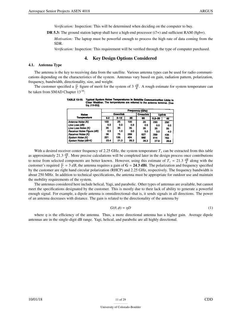
The antenna is the key to receiving data from the satellite. Various antenna types can be used for radio communi-cations depending on the characteristics of the system. Antennas vary based on gain, radiation pattern, polarization,frequency, bandwidth, directionality, size, and weight.
The customer specified a GTs
figure of merit for the system of 3 dBK . A rough estimate for system temperature can
be taken from SMAD Chapter 1310:
With a desired receiver center frequency of 2.25 GHz, the system temperature Ts can be extracted from this tableas approximately 21.3 dB
K . More precise calculations will be completed later in the design process once contributionsto noise from selected components are better known. However, using this estimate of Ts = 21.3 dB
K along with thecustomer’s required G
Ts= 3 dB, the antenna requires a gain of G = 24.3 dBi. The polarization and frequency specified
by the customer are right hand circular polarization (RHCP) and 2.25 GHz, respectively. The frequency bandwidth isabout 250 MHz. In addition to technical specifications, the antenna must be appropriate for outdoor use and maintainthe mobility requirements of the system.
The antennas considered here include helical, Yagi, and parabolic. Other types of antennas are available, but cannotmeet the specifications designated by the customer. This is mostly due to their lack of ability to generate a powerfulenough signal. For example, a dipole antenna is omnidirectional–that is, it sends signals in all directions. The powerof an antenna decreases with distance. The gain is related to the directionality of the antenna by
G(θ, φ) = ηD (1)
where η is the efficiency of the antenna. Thus, a more directional antenna has a higher gain. Average dipoleantennas are in the single-digit dB range. Yagi, helical, and parabolic are all highly directional.
10/01/18 11 of 29
University of Colorado-Boulder
CDD
Aerospace Senior Projects ASEN 4018 ARGUS
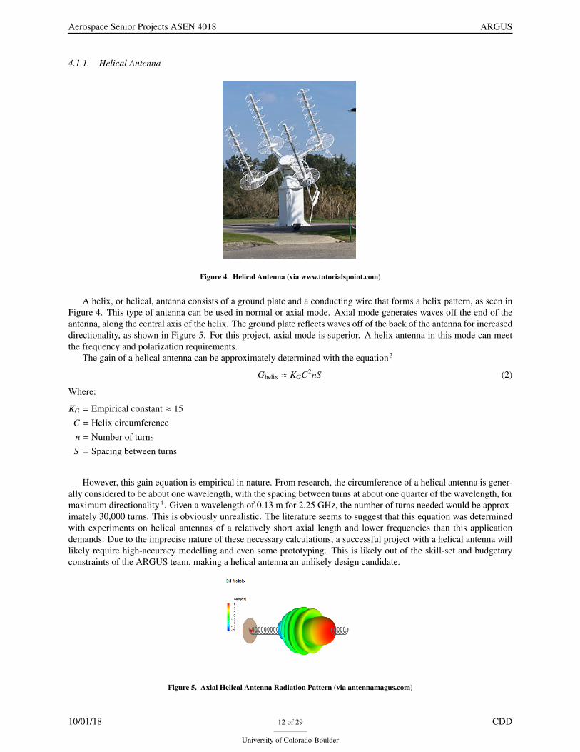
4.1.1. Helical Antenna
Figure 4. Helical Antenna (via www.tutorialspoint.com)
A helix, or helical, antenna consists of a ground plate and a conducting wire that forms a helix pattern, as seen inFigure 4. This type of antenna can be used in normal or axial mode. Axial mode generates waves off the end of theantenna, along the central axis of the helix. The ground plate reflects waves off of the back of the antenna for increaseddirectionality, as shown in Figure 5. For this project, axial mode is superior. A helix antenna in this mode can meetthe frequency and polarization requirements.
The gain of a helical antenna can be approximately determined with the equation3
Ghelix ≈ KGC2nS (2)
Where:
KG = Empirical constant ≈ 15C = Helix circumferencen = Number of turnsS = Spacing between turns
However, this gain equation is empirical in nature. From research, the circumference of a helical antenna is gener-ally considered to be about one wavelength, with the spacing between turns at about one quarter of the wavelength, formaximum directionality4. Given a wavelength of 0.13 m for 2.25 GHz, the number of turns needed would be approx-imately 30,000 turns. This is obviously unrealistic. The literature seems to suggest that this equation was determinedwith experiments on helical antennas of a relatively short axial length and lower frequencies than this applicationdemands. Due to the imprecise nature of these necessary calculations, a successful project with a helical antenna willlikely require high-accuracy modelling and even some prototyping. This is likely out of the skill-set and budgetaryconstraints of the ARGUS team, making a helical antenna an unlikely design candidate.
Figure 5. Axial Helical Antenna Radiation Pattern (via antennamagus.com)
10/01/18 12 of 29
University of Colorado-Boulder
CDD

Aerospace Senior Projects ASEN 4018 ARGUS
4.1.2. Yagi Antenna
A Yagi antenna is made up of a dipole antenna at the base with a reflector and several directors added parallel tothe dipole, as seen in Figure 6. The directors positively interfere with the dipole and increase the directionality andradiation pattern of the antenna depending on their separation distance, as seen in Figure 7. The length of the antennais generally proportional to the gain, so that more directors can be added to increase the gain. However, there is a limitto its length; the gain decreases with increasing number of directors after approximately fifteen directors5.
Figure 6. Yagi Antenna (via www.lairdtech.com)
Figure 7. Yagi Antenna Radiation Pattern (via www.rfwireless-world.com)
Despite its directionality and modifiability, there are several downsides to the Yagi. To achieve circular polar-ization, two Yagi arrays must be arranged at right angles5. This adds considerable weight and bulk to the system.Additionally, Yagi antenna gain is typically determined with an experimental table look-up, which will mean addi-tional testing would be necessary to find the definitive gain of the antenna.
4.1.3. Parabolic Antenna
A parabolic antenna is designed with a feed in the center of a parabolic dish. The parabola of the dish determinesthe focus and reflectivity of the signal emitted from the feed.
10/01/18 13 of 29
University of Colorado-Boulder
CDD

Aerospace Senior Projects ASEN 4018 ARGUS
Figure 8. Parabolic Antenna (via www.q-files.com)
The parabolic dish antenna provides the highest gain of the antennas considered here. This gain is directly propor-tional to the efficiency and diameter of the dish and inversely proportional to the wavelength of the frequency used.More specifically, the gain of a parabolic dish antenna can be calculated with
Gparabolic = η(πDλ
)2(3)
Where:
η = Aperture efficiencyD = Dish diameterλ =Wavelength
Assuming an efficiency of η = 50% and the required gain of 24.3 dBi, the diameter of the dish must be at leastD = 0.984 m. This is the best choice of size when compared to the Yagi or helical antennas. Right hand circularpolarization and the desired frequency range is easily achieved with a parabolic antenna. Furthermore, the dish canbe made out of mesh, which greatly decreases the wind loading on the antenna. The feed can be encapsulated in aweatherproof container and the dish has no electrical or moving parts that need to be protected from the weather.
Description Helical Yagi ParabolicThe antenna can be placed outdoors with minimal additional pro-tective cases
7 7 3
The generated signal can be pointed in a specific direction 3 3 3
The antenna can achieve the required gain with its largest dimen-sion 1.5 meters or less
7 7 3
The antenna can be made relatively lightweight while stillachieving the required gain
7 7 3
A single antenna can receive the required RHCP polarization 3 7 3
An antenna can be purchased off-the-shelf with the ability tocommunicate at the required frequency
7 3 3
No part of the antenna’s signal is blocked by its own components 3 3 7
The antenna’s contributions to a link budget are mathematicallywell-defined and do not require empirical modeling
7 7 3
The antenna’s 3dB beamwidth is large compared to alternatives,which allows for more wiggle-room in tracking precision
3 3 7
Table 2. Antenna Pros/Cons
4.2. Container/Rack - No Trade Study
The ground station needs a container to allow the user to be able to transport it and use it in various locations. Itmust be able to withstand weather conditions and must be light enough to be carried by two people. The kinds of
10/01/18 14 of 29
University of Colorado-Boulder
CDD

Aerospace Senior Projects ASEN 4018 ARGUS
containers ARGUS is considering are hard cases with handles, cases with wheels, large hiking backpacks, and cartswith wheels. The ground station will have different uses, either backcountry or remote locations. For the possiblefuture of ARGUS being a military reconnaissance aid out in the field, a backpack or a hard case that can be carriedbetween two people would be the most likely option due to their ease of transport. In order to comply with Departmentof Defense regulations for military gear and safety regulations, all cases will be cross referenced with InternationalProduct Outdoor Cases and will have a certificate by the company for guarantees and specifications.2
4.2.1. Hard Case
A hard case with handles would be a durable, compact, waterproof container that could hold the entirety of theground station’s components. This would be able to be transported to remote locations without the components beingdamaged. This case would be relatively light weight and would have lots of organized space. Most Pelican hard caseshave dual casing to protect the components from the elements as well as any submersion in water. The hard caseswill have a foam inside to protect the various components of the ground station, which can be cut into divisions tocompletely secure each part. Hard cases come in different sizes, but a medium size hard case with side handles caneasily be carried by two people. Therefore, cost based on the durability, inside foam protection, and buoyancy in caseof water will be key elements for the protection of all the ground station components.
4.2.2. Case With Wheels
A case with wheels would be a commercial, off-the-shelf, and variably sized container that could hold the entiretyof the ground station’s components. It would be an affordable and easily found option that could be replaced forfuture iterations. A case like this would be cased in plastic which allows for durability, but would be heavy anddifficult to carry. In addition, these cases would be difficult to transport on their wheels if the terrain was not perfect.Furthermore, if the wheels were used, it would be difficult to find an off the shelf affordable container like this thatwould be guaranteed to work in remote locations. In addition, most cases with wheels have handles to carry the case,yet they are not in easy access locations, making it quite difficult to carry.
4.2.3. Backpack
A large backpack would be a commercial, off the shelf, and easily portable option for the container for the project’sground station. Most backpacks are considered water resistant, light weight, and easy to carry. However, backpackslack a large space that could easily fit the components of the ground station. Also due to the size of our antenna andalso requirement to protect the antenna it will be harder to find a reasonable size backpack that can maintain all thecomponents secured.
4.2.4. Cart
A cart would allow for heavier components to be transported. However, the components would be open to damagefrom the environment, would not be able to be carried by two people, and would be difficult to transport over rockyand variable terrain. Moreover, a cart would most likely be the most expensive option. A cart would be a good optionif the ground station were to be transported in and out of a building on flat terrain, but it would be very difficult andheavy to move over variable terrain likes rocks and dirt. Transportation carts can be used by Raytheon when loadingand unloading the ground station from an aircraft if this were to be shipped, but the ground station itself should be inone case for the success of this project.
Description Hard Case Case with Wheels Backpack CartThe container can be knocked over or dropped from short dis-tances with little damage to components
3 3 7 7
The container can be picked up and carried easily over long dis-tances
3 7 3 7
The container is lighter than alternatives 3 7 3 7
Space within the container can be structured and well-organized 3 3 7 3
The container is not prohibitively expensive 3 3 3 7
Table 3. Container Pros/Cons
10/01/18 15 of 29
University of Colorado-Boulder
CDD

Aerospace Senior Projects ASEN 4018 ARGUS
With the table listed above, it is clear which option the team will use as the container for the components. TheHard Case, with handles for hassle-free carrying, is the most advantageous choice that fits all of the project’s needs.Therefore, there will be no trade study done. It is likely that the team will consider the Pelican iM2450, MonopriceWeatherproof Hard Case, and the Condition 1 16inch Medium Case as possible options for the actual container.All these cases are not only certified by the Department of Defense’s International Product Outdoor Cases, but alsorecommended by various outdoor personnel of multiple status (military, hobbies, hunters etc).
4.3. Central Processor - No Trade Study
4.3.1. Small Single-Board Computer
The first option looked at for a processor was a small single-board computer for the tracking software. This is acheap option, however may not have the processing power and speed to be able to both track the satellite and handlethe SDR output. Some examples looked at were the Raspberry Pi 3 Model B+ (pictured below), the BeagleBoneBlack, and the Odroid XU4. It was determined that this was not a good option to be able to handle the SDR output,and a separate computer would be needed to handle the user interface.
Figure 9. Raspberry Pi 3 - Model B Plus (https://www.raspberrypi.org/products/raspberry-pi-3-model-b-plus/)
4.3.2. Laptop
The other option looked at was to use a Laptop as both the user interface and the processor. This is a better optionthan the small single-board computer, as it should have a lot more processing power as long as it has a high-qualityprocessor such as an Intel Core i7 or i9. The laptop seems to be a much more expensive option, but a laptop isnecessary in either case to interface with the ground station so in reality it is cheaper to combine all functionality intoone computer. This makes the laptop a much better option than the small single-board computer. Some options theteam is considering are the Inspiron 15 5000 (pictured below), the Acer Travelmate 4, and the Lenovo Ideapad 530s.
Figure 10. Inspiron 15 5000 (https://www.dell.com/)
10/01/18 16 of 29
University of Colorado-Boulder
CDD
Aerospace Senior Projects ASEN 4018 ARGUS
4.4. Tracking Software
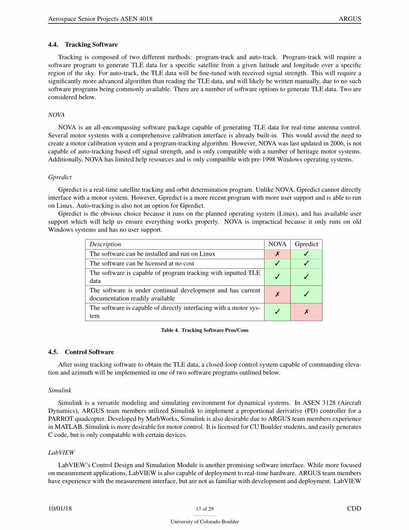
Tracking is composed of two different methods: program-track and auto-track. Program-track will require asoftware program to generate TLE data for a specific satellite from a given latitude and longitude over a specificregion of the sky. For auto-track, the TLE data will be fine-tuned with received signal strength. This will require asignificantly more advanced algorithm than reading the TLE data, and will likely be written manually, due to no suchsoftware programs being commonly available. There are a number of software options to generate TLE data. Two areconsidered below.
NOVA
NOVA is an all-encompassing software package capable of generating TLE data for real-time antenna control.Several motor systems with a comprehensive calibration interface is already built-in. This would avoid the need tocreate a motor calibration system and a program-tracking algorithm. However, NOVA was last updated in 2006, is notcapable of auto-tracking based off signal strength, and is only compatible with a number of heritage motor systems.Additionally, NOVA has limited help resources and is only compatible with pre-1998 Windows operating systems.
Gpredict
Gpredict is a real-time satellite tracking and orbit determination program. Unlike NOVA, Gpredict cannot directlyinterface with a motor system. However, Gpredict is a more recent program with more user support and is able to runon Linux. Auto-tracking is also not an option for Gpredict.
Gpredict is the obvious choice because it runs on the planned operating system (Linux), and has available usersupport which will help us ensure everything works properly. NOVA is impractical because it only runs on oldWindows systems and has no user support.
Description NOVA GpredictThe software can be installed and run on Linux 7 3
The software can be licensed at no cost 3 3
The software is capable of program tracking with inputted TLEdata
3 3
The software is under continual development and has currentdocumentation readily available
7 3
The software is capable of directly interfacing with a motor sys-tem
3 7
Table 4. Tracking Software Pros/Cons
4.5. Control Software
After using tracking software to obtain the TLE data, a closed-loop control system capable of commanding eleva-tion and azimuth will be implemented in one of two software programs outlined below.
Simulink
Simulink is a versatile modeling and simulating environment for dynamical systems. In ASEN 3128 (AircraftDynamics), ARGUS team members utilized Simulink to implement a proportional derivative (PD) controller for aPARROT quadcopter. Developed by MathWorks, Simulink is also desirable due to ARGUS team members experiencein MATLAB. Simulink is more desirable for motor control. It is licensed for CU Boulder students, and easily generatesC code, but is only compatable with certain devices.
LabVIEW
LabVIEW’s Control Design and Simulation Module is another promising software interface. While more focusedon measurement applications, LabVIEW is also capable of deployment to real-time hardware. ARGUS team membershave experience with the measurement interface, but are not as familiar with development and deployment. LabVIEW
10/01/18 17 of 29
University of Colorado-Boulder
CDD

Aerospace Senior Projects ASEN 4018 ARGUS
is more desirable for motor control. It is licensed for CU Boulder students, and easily generates C code, while havinga comprehensive embedded development module.
The pros and cons for each software are tabulated below.
Description Simulink LabviewTeam members are more familiar with the framework 3 7
The program is licensed by the University of Colorado 3 3
Hardware deployment is compatible with a wide array of devices 7 3
The program easily generates C code to interface with hardware 3 3
Table 5. Control Software Pros/Cons
4.6. Radio - No Trade Study
In order to track the satellite using signal communication, as well as receive data from the satellite, a radio mustbe implemented in the design of the ground station. This will aid in the tracking of the satellite as the ground stationdish and antenna track across the sky. For this system, the frequency in which RX will be operating is 2.1 GHz - 2.3GHz. Given the data rate of 2 Mbps, the necessary resolution was calculated to be between 8-12 bits. The maximumbandwidth of the radio is 2 MHz, which is proportional to the data rate given the QPSK demodulation scheme. Withthis information and the requirements established by the customer, a trade study will be performed to determine whichradio system is the most qualified and cost effective. An important aspect that will be taken into consideration will bethe portability and mobility of the radio, this ties into the motivation for this project.
HAM Radio
An amateur radio (HAM radio) can transmit and receive radio signals in which ever frequency is desired. Thisradio requires licensing and is often times bulky. There are a transceiver systems that can be implemented for receiveand transmit capabilities, these systems are expensive but it is comparable to buying two separate receive and transmitradios.
Software Defined Radio
A Software Defined Radio (SDR) can cover a wide range of frequency as well as large bandwidths. This systemis also small, which aids in keeping the ground system mobile and portable. The SDR is compatible with software todemodulate the signal. The software that will be used in partnership with the SDR is GNU radio, an open source freetoolkit for these applications.
Description HAM SDRThe radio system does not require a significant portion of thebudget
7 7
The radio system is well-documented 3 3
The radio system is small and light enough to be comfortablycarried by one person over a long distance
7 3
The radio system can be reconfigured to handle signals with dif-ferent frequencies and modulation schemes
7 3
The radio system only requires one unit to be capable of trans-mitting as well as receiving
7 3
Table 6. Radio Pros/Cons
4.7. Low-Noise Amplifier - No Trade Study
A low-noise amplifier (LNA) must be used when downlinking data from a satellite. This is because the receivedsignal will be too weak for the SDR to accurately convert to a digital signal. Each LNA considered has SMA-type
10/01/18 18 of 29
University of Colorado-Boulder
CDD

Aerospace Senior Projects ASEN 4018 ARGUS
connections and require a constant DC voltage as they are an active component. All considered LNAs are configuredsimilar to the following image.
Figure 11. Low-Noise Amplifier (via minicircuits.com)
LNAs differ from one another in their frequency window, signal gain in dB, noise floor levels in dB, and connectortypes. There is no trade study necessary at this stage of the project, but an LNA will end up being used. Until theexact link budget is finished it will be unknown what signal gain will be needed to close the link between the groundstation and the satellite. A low noise amplifier is preferred because the automatic track function will likely follow thehighest signal-to-noise ratio. Therefore, background noise and signals outside of the desired frequency window shouldbe minimized. LNAs have a more narrow band and lower noise figure than most other types of amplifiers.
4.8. Motor Hardware
In pursuit of designing a two axis (azimuth and elevation) pointing system, motor hardware is at the forefront ofmaking the system possible. Some simple back of the envelope calculations determined that a motor between 5 to 25Nm would be required to point and hold the elevation component of the antenna. This number is fairly high, limitingavailable motors. Additional research will be done to more accurately determine the required torque once a baselinedirection has been decided. There are numerous kinds and types of motors to consider including; AC, DC brushless,direct drive, servos, stepper, and torque motors. Each of these motors are very applicable for the intended design, buteach has drawbacks if used.
AC
An AC motor is one of the most common types of motors available. AC motors use the basic concepts of elec-tromagnets and rotating shafts. One main concern with this selection would be the use of electromagnets, which cancause interference with radio signals. In addition, most general AC motors use analog controls based on frequencymanipulation. This would require the use of an encoder to determine position and a motor controller to control speed.
DC Brushless
Brushless DC motors are a type of synchronous motor which receive a DC current that passes through an inverteror switching power supply to drive the motor phases. Due to the fact that the alternating power supply is created by anembedded controller, DC motor have the advantage of excellent speed control in both directions yet are less efficientthan AC motors. Additionally, DC motors are characteristic for high power to weight ratios and high speeds.
Direct Drive
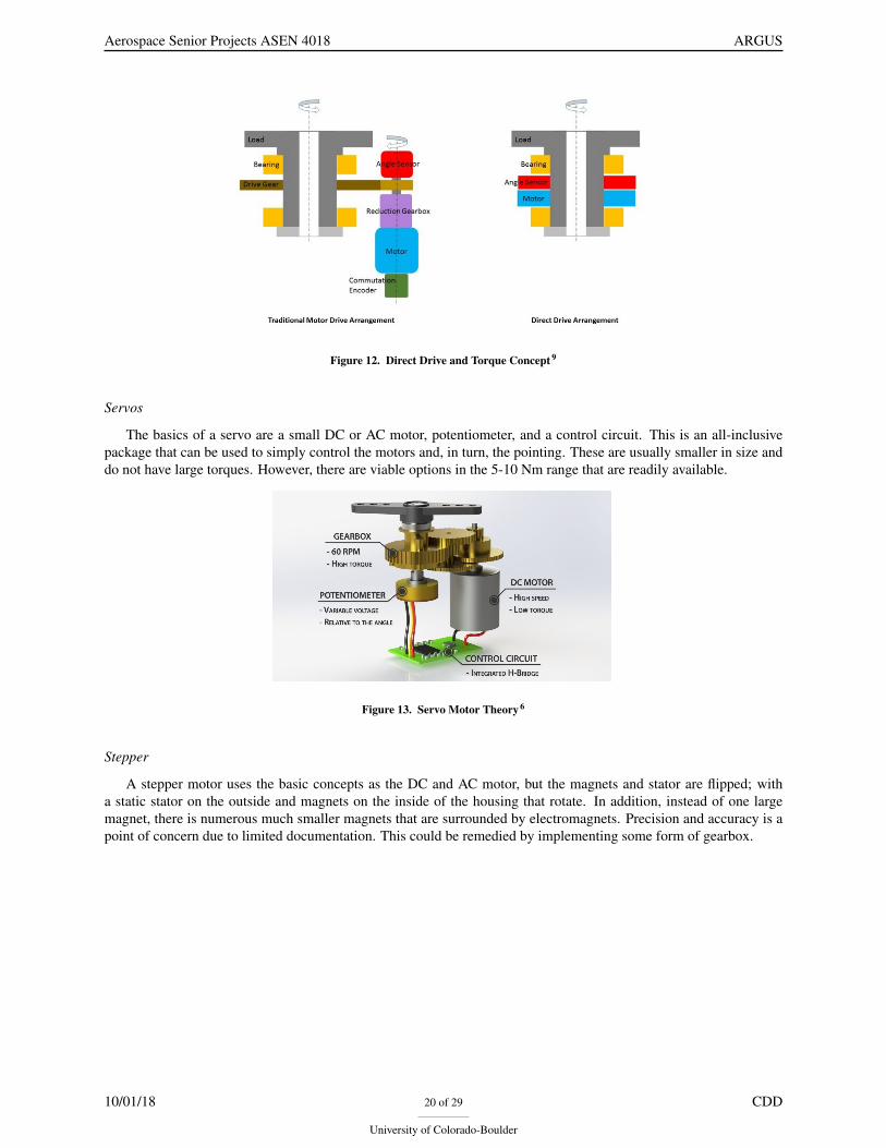
Direct drive motors are a type of permanent-magnet synchronous motor, in which the power is directly providedfrom the shaft to the load. This is advantageous because it eliminates the need for any belt or gear system resultingin a lower torque-inertia ratio. This means less torque required to accelerate the motor and increased speed control.Additionally, the direct drive motor requires fewer moving parts than alternative electric motors meaning, decreasedsize and complexity, and increased life span. Direct drive motors are also susceptible to torque ripple during operation.Overall direct drive type motors are small, lightweight, low power, and provide optimal speed control.
10/01/18 19 of 29
University of Colorado-Boulder
CDD
Aerospace Senior Projects ASEN 4018 ARGUS
Figure 12. Direct Drive and Torque Concept 9
Servos
The basics of a servo are a small DC or AC motor, potentiometer, and a control circuit. This is an all-inclusivepackage that can be used to simply control the motors and, in turn, the pointing. These are usually smaller in size anddo not have large torques. However, there are viable options in the 5-10 Nm range that are readily available.
Figure 13. Servo Motor Theory 6
Stepper
A stepper motor uses the basic concepts as the DC and AC motor, but the magnets and stator are flipped; witha static stator on the outside and magnets on the inside of the housing that rotate. In addition, instead of one largemagnet, there is numerous much smaller magnets that are surrounded by electromagnets. Precision and accuracy is apoint of concern due to limited documentation. This could be remedied by implementing some form of gearbox.
10/01/18 20 of 29
University of Colorado-Boulder
CDD

Aerospace Senior Projects ASEN 4018 ARGUS
Figure 14. Stepper Motor Theory 7
Figure 15. Stepper Motor 7
Torque
A torque motor is a specialized form of electric motor which can operate indefinitely while stalled, that is, with therotor blocked from turning, without incurring damage. Torque motors is less of a type of motor, but a special versionof a motor. This is still an attractive option due to operating near stall conditions. These motors produce large torquesat low to no RPMs. One downside of all the available torque is these motor tend to be very expensive, and will stillrequire an encoder to determine position.
Description AC DC DD Servo Stepper TorqueCan generate enough torque to point antenna 3 3 3 3 3 3
Accurate enough to meet pointing criteria 3 3 3 3 7 3
Within budget 3 3 3 7 3 7
Uses digital control/input 7 7 3 3 3 3
Robust/Reliable 3 3 3 7 3 3
Feedback Sensor Included 7 7 7 3 3 3
Light and small 7 3 3 3 7 3
Table 7. Motor Hardware Pros/Cons
At the conclusion of the research for each of these viable options, all still remained valid solutions. In addition, theneed for a digital format was determined to be essential over an analog motor, as determined by other group membersas to not require a DAC. The importance of having high torque at low RPMs was another essential constraint. Thisincluded stepper, torque and direct drive. With this information in mind, a trade study will be conducted on all possiblemotors to determine the ideal motor type for the system.
5. Trade Study Process and Results5.1. Antenna Type
One ARGUS critical project element is closing the communications link budget, and the main contribution to thisproject element is the design of an antenna. With this in mind, the first design decision for an antenna is choosing ageneral type of antenna. For reasons discussed earlier, the team is considering three different types: helical, yagi, andparabolic. Several criteria have been selected to choose this critical design component, and are discussed in Table 8below.
10/01/18 21 of 29
University of Colorado-Boulder
CDD

Aerospace Senior Projects ASEN 4018 ARGUS
Criteria Weight Rationale
Size-to-Gain 20% Portability is a CPE, so the antenna size should be small relative to thegain it is able to produce.
Beamwidth Size 10% A larger beamwidth allows tracking accuracy requirements to be lessstrict.
Available COTS 35%Having available components-off-the-shelf at the required gain relievespressure on the design process for a component that team membershave little experience with.
Ease of Modeling 35%Having strong analytical knowledge of an antenna system’sperformance is vital to properly modeling the system andunderstanding how it will behave upon construction.
Table 8. Antenna Type Criteria Definitions
A large beamwidth size would make designing the tracking system easier, but this is ultimately less important thanthe other criteria listed here. The size-to-gain is important to designing a portable system; however, both the availabilityof components off-the-shelf and ease of modelling are vital to obtaining any level of success in this project. The levelsof these criteria are tabulated below.
10/01/18 22 of 29
University of Colorado-Boulder
CDD

Aerospace Senior Projects ASEN 4018 ARGUS
Criteria 1 2 3 4 5
Size-to-Gain
Achieving therequired gainnecessitates anantenna thatdoes not fit in apickup truck
Achieving therequired gainnecessitates anantenna that fitsin a pickuptruck
Achieving therequired gainnecessitates anantenna that canbe rolled by twopeople
Achieving therequired gainnecessitates anantenna that canbe carried bytwo people
Achieving therequired gainnecessitates anantenna that canbe carried byone person
BeamwidthSize
The antenna canproduce a 3dBbeamwidthsmaller than 5°at the requiredgain
The antenna canproduce a 3dBbeamwidthsmaller than10° at therequired gain
The antenna canproduce a 3dBbeamwidthsmaller than15° at therequired gain
The antenna canproduce a 3dBbeamwidthsmaller than20° at therequired gain
The antenna canproduce a 3dBbeamwidthsmaller than25° at therequired gain
AvailableCOTS
Fewcomponents areavailableoff-the-shelf,and othercomponentscannot be easilymanufactured
Fewcomponents areavailableoff-the-shelf,and othercomponents canbe easilymanufactured
Mostcomponents areavailableoff-the-shelf,with theexception of adifficult-to-manufacturecomponent
Mostcomponents areavailableoff-the-shelf,with theexception of aneasily-manufacturablecomponent
The entireantenna systemis availableoff-the-shelf
Ease ofModeling
No analyticalexpressionsexist forantennaperformanceand noempiricalapproximationsexist for thisapplication’sfrequency andgainrequirements
No analyticalexpressionsexist forantennaperformance,but empiricalapproximationsexist for thisapplication’sfrequency andgainrequirements
Approximateanalyticalexpressionsexist forantennaperformanceand cannot beeasilyoptimized withsome modeling
Approximateanalyticalexpressionsexist forantennaperformanceand can beoptimized withsome modeling
Clear analyticalexpressionsexist forantennaperformance
Table 9. Antenna Type Criteria Levels
These criteria have been applied to the three types of antennas, seen in Table 10. As discussed in the key designoptions, the size of both the Yagi and helix antennas increase with an increase in gain. The beamwidth size is better forthe Yagi, but the ease of modeling is far less. The helical antenna has slightly better modeling options, though neitherare as accurate as that available for a parabolic antenna.
Helical Yagi ParabolicSize-to-Gain 1 2 5
Beamwidth Size 3 4 2Available COTS 1 2 5
Ease of Modeling 3 1 5Weighted Total 1.90 2.45 4.70
Table 10. Antenna Type Scoring
Overall, it has been determined that the parabolic antenna is the best choice for ARGUS. There are many optionsavailable off the shelf at the desired frequency, gain, and polarization. Many of these options are small enough to meetthe mobility requirement, while larger ones will still fit in the back of a truck. Finally, the parabolic system will be
10/01/18 23 of 29
University of Colorado-Boulder
CDD

Aerospace Senior Projects ASEN 4018 ARGUS
easy to model and verify. The beamwidth, as explained in the scoring, is not as critical as these other elements.
5.2. Control Software
Simulink and Labview are the two software programs of interest for motor control. Four criteria areas are used ona one to five scale to determine ranking and are specified by Table 11 below.
Criteria Weight Rationale
User support 30% Online assistance or from CU students/faculty is critical for whenproblems arise.
Team Experience 30% Less problems will arise with previous team knowledge.
Hardware Compatibility 30% Selection of hardware should not be contingent on compatiblesoftware.
User Interface Compatibility 10% GUI-oriented programs helpful but not necessary.
Table 11. Control Software Criteria Definitions
Both user support, team experience, and hardware compatibility have the same 30% weight. It is equally importantto have the resources and hardware compatibility for a successful control system. The user interface compatibility isweighted significantly lower at 10%. While a user interface would make the control system more user-friendly, it isnot required.
The scoring level criteria is given in Table 12. A score of one is the least-desirable (red), and five is the most-desirable (green). The final scoring between the two programs is given in Table 13.
The elected control software after scoring is Simulink. While both programs are equally capable, the ARGUSteam has more experience with Simulink (and/or MATLAB). Despite a score of 3 in team experience, there are manyresources available on the CU campus as well as online for troubleshooting.
Criteria 1 2 3 4 5
User Support Not supported No longersupported
Current,minimalsupport
Current, fullsupport
Currentlysupported w/online andon-campusresources
TeamExperience None
1 member w/minimalexperience
1 member w/proficientexperience
1+ membersw/ proficientexperience
Full teamexperience
HardwareCompatibility
Nocompatibleexternalhardware
1-2compatibledevices/-drivers
2-5compatibledevices
5-10compatibledevices
10+compatibledevices
User InterfaceCompatibility Not supported
Supported butnot well-documented,hard toimplement
Supportedand well-documented,hard toimplement
Moderate inimplementa-tion
Fullysupported andeasilyimplemented
Table 12. Control Software Criteria Levels
10/01/18 24 of 29
University of Colorado-Boulder
CDD
Aerospace Senior Projects ASEN 4018 ARGUS
Simulink LabViewUser Support 5 5
Team Experience 3 1Hardware Compatibility 5 5
User Interface Compatibility 5 5Weighted Total 4.4 3.8
Table 13. Control Software Scoring
5.3. Motor Hardware
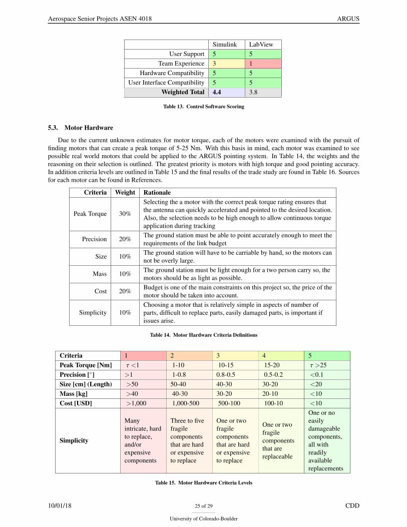
Due to the current unknown estimates for motor torque, each of the motors were examined with the pursuit offinding motors that can create a peak torque of 5-25 Nm. With this basis in mind, each motor was examined to seepossible real world motors that could be applied to the ARGUS pointing system. In Table 14, the weights and thereasoning on their selection is outlined. The greatest priority is motors with high torque and good pointing accuracy.In addition criteria levels are outlined in Table 15 and the final results of the trade study are found in Table 16. Sourcesfor each motor can be found in References.
Criteria Weight Rationale
Peak Torque 30%
Selecting the a motor with the correct peak torque rating ensures thatthe antenna can quickly accelerated and pointed to the desired location.Also, the selection needs to be high enough to allow continuous torqueapplication during tracking
Precision 20% The ground station must be able to point accurately enough to meet therequirements of the link budget
Size 10% The ground station will have to be carriable by hand, so the motors cannot be overly large.
Mass 10% The ground station must be light enough for a two person carry so, themotors should be as light as possible.
Cost 20% Budget is one of the main constraints on this project so, the price of themotor should be taken into account.
Simplicity 10%Choosing a motor that is relatively simple in aspects of number ofparts, difficult to replace parts, easily damaged parts, is important ifissues arise.
Table 14. Motor Hardware Criteria Definitions
Criteria 1 2 3 4 5Peak Torque [Nm] τ <1 1-10 10-15 15-20 τ >25Precision [◦] >1 1-0.8 0.8-0.5 0.5-0.2 <0.1Size [cm] (Length) >50 50-40 40-30 30-20 <20Mass [kg] >40 40-30 30-20 20-10 <10Cost [USD] >1,000 1,000-500 500-100 100-10 <10
Simplicity
Manyintricate, hardto replace,and/orexpensivecomponents
Three to fivefragilecomponentsthat are hardor expensiveto replace
One or twofragilecomponentsthat are hardor expensiveto replace
One or twofragilecomponentsthat arereplaceable
One or noeasilydamageablecomponents,all withreadilyavailablereplacements
Table 15. Motor Hardware Criteria Levels
10/01/18 25 of 29
University of Colorado-Boulder
CDD

Aerospace Senior Projects ASEN 4018 ARGUS
AC DC Direct Drive Servo Stepper TorquePeak Torque 5 5 5 3 2 5
Precision 3 3 5 5 2 5Size 4 3 5 3 5 4
Mass 1 4 4 5 5 5Cost 3 3 4 2 4 3
Simplicity 4 4 5 3 5 5Weighted Total 3.6 3.8 4.7 3.4 3.3 4.5
Table 16. Motor Hardware Trade Study
As can be seen from Table 16 direct drive and torque motor are ahead of the other candidates. This is due to thesimilarity between the two motors, but direct drive is the ideal selection based on the above trade study.
5.4. Flowchart of Trade Study Selections
ARGUS can be broken down into three generally separate sections. Figure 16 shows the progression the projecthas taken through key design considerations and down into the trade study. The elements in green are the winningresults of the trade study for each section.
10/01/18 26 of 29
University of Colorado-Boulder
CDD

Aerospace Senior Projects ASEN 4018 ARGUS
Figure 16. Summary of ARGUS’s Trade Study Selections
6. Selection of Baseline Design6.1. Central Processor
The central processor unit was determined to be a laptop. The required sample rate is 5 MHz which can only beachieved using a laptop (with a processor at least as powerful as an Intel i7) connected to the SDR. This will allowthe user to process the data real-time, track the satellite (program and auto track), and collect telemetry data. Thesecond reason for choosing a laptop is it contains a user interface. In order to downlink from the satellite and testrequirements, a radio-commanding user interface is required. A single small board computer cannot run software likethis and does not have the interface to allow command if it could. Similarly, the tracking software would be difficult oreven impossible to use without some kind of interface. Lastly, the central processor must be capable of computing thetracking algorithm that will command the motors. The use of a laptop provides flexibility on what type of algorithm,language, and user interface used. The laptop is the clear choice, as a small single-board processor would not befeasible to be controlled by a user.
10/01/18 27 of 29
University of Colorado-Boulder
CDD

Aerospace Senior Projects ASEN 4018 ARGUS
6.2. Antenna Type
The antenna best suited for this design is a parabolic antenna. Through the key design analysis, the parabolicshaped antenna was found to be the type best for satisfying the design requirements. The gain, polarization andfrequency requirements are all met through the parabolic dish. These factors cannot be compromised, as the entiresystem will not work without the correct specifications. Furthermore, this type of dish is also lightweight and fairswell in meeting the size requirements at the necessary gain. Overall, the parabolic dish is the best design to satisfy ourdesign requirements.
6.3. Radio
The team will use an SDR as the radio system, which was determined through research and comparison of HAMradio transceivers and receivers. The SDR is a smaller system that would be required for a hardware based radio. AnSDR is also more flexible in varying the frequency. This system is more complicated than a hardware based radio dueto its configuration requiring the usage of Linux programming; however, it is also less expensive than a hardware basedradio. The SDR is the best fit for radio hardware and signal processing to ensure modularity to different frequencies,cost, and size advantages. It is also of key importance to the digital data processing required. It will interface with asoftware on the computer which is able to control the SDR and graphically show output for validation.
6.4. Motor System
The motor type chosen to best satisfy the needs of the system was the direct drive motor. This decision was basedoff of the on the pros/cons and trade study performed earlier in this document. Direct drive motors were the optimalchoice because of their ability to produce and sustain significant torques at low to zero RPM. Additionally, directdrive motors experience little to no backlash, are small relative to their torque output, and are relatively simply in bothconstruction and maintenance. Lastly, a direct drive motor can be coupled with a high resolution encoder to deliveraccurate angular position and rate information.
6.5. Control Software
While equally capable programs, the results of the trade study placed Simulink at 4.4/5 and Labview at 3.8/5. Thisis due entirely to the increased team experience with Simulink. Therefore, Simulink will be used for implementing theauto and program-tracking algorithms. Within Simulink there are multiple control design toolboxes capable of hard-ware deployment. While ARGUS team members have little experience in Simulink, their experience using MATLABcan be easily translated.
6.6. Container Type
The container the team determined is most beneficial for ARGUS is a hard cased carry container. This containeroption would have durable handles and would be lightweight for two person carry. It would be durable enough totransport the components to remote locations without damage and would be spacious enough for organized storagewith foam protection. The other options all had disadvantages that detracted from their appeal and only workedunder very specific circumstances. This does not comply with our main goal of two person carry ground station withbackcountry use. The pros and cons for each are listed earlier in the document, and the hard cased carry containeris the obvious choice. The team is currently looking into possible options for the hard carry cases, but the PelicaniM2450, Monoprice Weatherproof Hard Case, and the Condition 1 16inch Medium Case are the most likely optionsfor this.
6.7. Tracking Software
The tracking software we determined is the most applicable for our use is Gpredict. This is because it is a freeopen-source software which can be run on Linux. Our SDR will run Linux, and the rest of our code will be mucheasier to run on a Linux system than any other operating system. It has an excellent user interface, and can output alist of elevation and azimuth angles for our antenna to point towards during any given pass. It has the ability to controlthe motor, but this will most likely not be used because this can only use the program track function; this means theimplementation of auto-track will require a different software using the azimuth and elevation angles from Gpredictas inputs. Gpredict will simply be used to track the satellite using TLE data, transform the output into azimuth andelevation angles based on the ground station location, and output to the separate motor control software.
10/01/18 28 of 29
University of Colorado-Boulder
CDD

Aerospace Senior Projects ASEN 4018 ARGUS
References[1] Thilker, Steve. “Small Satellite Ground Terminal,” Raytheon, Retrieved September 4, 2018, from https://
canvas.colorado.edu.
[2] BW Container Trade Study “Outdoor Cases Military Grade”, September 23, 2018. from https://www.b-w-international.com/products/outdoor-cases/
[3] Volakis, John.“Antenna Engineering Handbook”, Retrieved from September 28, 2018 fromhttps://www-accessengineeringlibrary-com.colorado.idm.oclc.org/browse/antenna-engineering-handbook-fourth-edition#p200129ad99703_1001
[4] Kraus, John.“Antennas for All Applications”, Retrieved from September 28, 2018 fromhttps://www.researchgate.net/profile/Sajeed_Mulla/post/If_the_E-Field_pattern_of_an_antenna_varies_as_a_bcostheta_where_a_b_are_some_integers_Then_how_to_calculate_the_HPBW/attachment/59d6465c79197b80779a1611/AS3A457537502879744401486096849945/download/John.+D.+Kraus2C+Ronald+J.+Marhefka-Antennas-for-All-Applications.pdf
[5] Poole, Ian.“Yagi Antenna Theory”, Retrieved from September 28, 2018 from https://www.radio-electronics.com/info/antennas/yagi/yagi-antenna-gain.php
[6] Parker Motin, ”BE Series Motors”. BE344 J Motor Data Sheet. September 30, 2018 from http://www.parkermotion.com/products/Rotary_Servo_Motors__5209__30_32_80_567_29.html.
[7] Lin Engineering. ”E5718 Series High Torque Stepper Motor”. Standard Motors. September29, 2018 from https://www.linengineering.com/products/stepper-motors/e5718-series-high-torque-stepper-motor/#fndtn-standard_motor.
[8] ETEL. ”TML Torque Motors - Specifications”. Data Sheet. September 28, 2018 from https://www.etel.ch/torque-motors/tml/specifications/.
[9] Howard, Mark. ”Direct Drives & Direct Sensors”. September 27, 2018 from https://www.zettlex.com/articles/direct-drives-direct-sensors/.
[10] Wiley J. Larson and James R. Wertz, ”Communications Architecture.” Space Mission Analysis and Design,Microcosm Press, 2010, pp. 533-585.
10/01/18 29 of 29
University of Colorado-Boulder
CDD