
Conceptual Design and Analysis of Roads and Road ...
206
Conceptual Design and Analysis of Roads and Road Construction Machinery for Initial Lunar Base Operations Submitted to: Mr. James Aliberti NATIONAL AERONAUTICS AND SPACE ADMINISTRATION Kennedy Space Center Florida Prepared by: Joel Banks Keyanoush Efatpenah Jeffrey L. Sines (Team Leader) Mechanical Engineering Department THE UNIVERSITY OF TEXAS AT AUSTIN Austin, Texas Spring 1990 "iJc :_L .... Y i :iT _,^L,, i.. };," _.:, ":Liri_+'tl-T;;_ . t T "" ,+, !!iiiv. 7 _,,', C<:t;.[ ] __'"
Transcript of Conceptual Design and Analysis of Roads and Road ...

Conceptual Design and Analysisof Roads and Road Construction Machinery
for Initial Lunar Base Operations
Submitted to:
Mr. James Aliberti
NATIONAL AERONAUTICS AND SPACE ADMINISTRATION
Kennedy Space Center
Florida
Prepared by:
Joel Banks
Keyanoush Efatpenah
Jeffrey L. Sines (Team Leader)
Mechanical Engineering Department
THE UNIVERSITY OF TEXAS AT AUSTIN
Austin, Texas
Spring 1990
"iJc :_L .... Y i :iT _,^L,, i.. };," _.:, ":Liri_+'tl-T;;_ .
t T "" ,+, !!iiiv. 7 _,,', C<:t;.[ ] __'"

MECHANICAL ENGINEERING DESIGN PROJECTS PROGRAM
THE UNIVERSITY OF TEXAS AT AUSTIN
ETC 4.102" Austin, Texas 78712-1063" ( 512 ) 471-3900
9 April 1990
Mr. James Aliberti
Mail Stop PT-PMONational Aeronautics and Space AdministrationKennedy Space Center, Florida 32899
Dear Mr. Aliberti:
Attached is our final report for the design of a road construction system for initiallunar base operations. Our design team selected a compacted lunar soil road as the mostfeasible type of road for initial lunar base operations and concluded that only a grader andcompactor were necessary to build this road. The road construction system we developedconsists of a main drive unit for propulsion and control, a detachable grader assembly, anda towed compactor.
This report contains a complete description of the alternate designs we investigated,our decision matrices, and the final design solution we developed, including machineryconfiguration, mass, and power requirements, and operating features of each of the threemachines. We also present a thorough evaluation of the design and recommendations forfurther work.
It has been a pleasure working on this project for NASA/USRA, and we look
forward to seeing you at our design presentation. The presentation will take place onTuesday, April 24, 1990, at 10:00 am in the Engineering Teaching Center II, Room 4.110,on the campus of The University of Texas at Austin. A catered luncheon will follow the
presentation.
Sincerely,
Joel Banks
oush Efatpen_
Jeffrey Sines, Team Leader

AC KNOWLEDGEMENTS
The design team members thank the National Aeronautics and Space Administration
and the Universities Space Research Association (NASA/USRA) for sponsoring this
project and Mr. James Aliberti for his continued support of our project.
We thank Mr. Richard B. Connell (NASA/USRA contact engineer) for his
assistance throughout the semester. Mr. Connell helped clarify our design problem, gave
us guidance at critical times during the project, and provided much needed morale boosts.
A special thanks goes to Dr. Kristin Wood (faculty advisor) for his unending
support and valuable technical expertise on many different areas of our project. His
enthusiasm and optimism gave us a positive attitude for our project at all times and made us
strive to produce the best design we could.
We also thank Mr. Brian Muirhead and Mr. Don Bickler (JPL engineers) for their
assistance in the areas of material selection and lunar soil mechanics. Mr. Frank Wood (of
the New Mexico State Highway and Transportation Department) provided much needed
information on terrestrial road construction and machinery.
We also express our appreciation to Professor Torfason for helping us maintain our
design notebooks, to Mr. Wendell Deen for critiquing our design drawings, and to Mr.
Bert Herigstad for providing administrative services, material, and advice.
Finally, we would like to thank Dr. Steven P. Nichols for overseeing the
Mechanical Engineering Design Projects Program and providing informative and practical
lectures on the many different aspects of engineering.

ABSTRACT
Conceptual Design and Analysis of Roads and Road Construction
Machinery for Initial Lunar Base Operations
Recent developments have made it possible for scientists and engineers to considerreturning to the Moon to build a manned lunar base. The base can be used to conductscientific research, develop new space technology, and utilize the natural resources of theMoon. Areas of the base will be separated, connected by a system of roads that reduce the
power requirements of vehicles traveling on them. For a senior design project sponsoredby the University of Texas Mechanical Engineering Design Project Program, NASA/USRAasked the design team to analyze feasible road types for the lunar surface and design a roadconstruction system for initial lunar base operations. The design team also constructed amodel to show the system configuration and key operating features.
The alternate designs for the lunar road construction system were developed in fourstages: analyze and select a road type, determine operations and machinery needed toproduce the road, develop machinery configurations, and develop alternates for severalmachine components.
The design team selected a compacted lunar soil road for initial lunar base
operations. The only machinery required to produce this road were a grader and acompactor. The road construction system the design team developed consists of a maindrive unit which is used for propulsion, a detachable grader assembly, and a towedcompactor.
KEY WORDS: MOTOR GRADER, COMPACTOR, ROAD CONSTRUCTION,LUNAR BASE
Joel Banks
Jeffrey Sines, Team Leader
°..
Ill

TABLE OF CONTENTS
ACKNOWLEDGEMENTS ...................................................................... ii
ABSTRACT ...................................................................................... iii
TABLE OF CONTENTS ....................................................................... iv
LIST OF FIGURES ............................................................................. vi
LIST OF TABLES ............................................................................... ix
INTRODUCTION ................................................................................ 1
Background ................................................................................. 1Project Requirements ...................................................................... 4Design Criteria .............................................................................. 4Solution Methodology ..................................................................... 6
ALTERNATE DESIGNS ........................................................................ 7
Selection of a Feasible Road Type ....................................................... 8Characteristics of Road Surfaces ................................................ 8
Road Type Selected .............................................................. 11
Construction Processes and Machinery Selection ..................................... 13Machinery Configurations ................................................................ 15
Graders ............................................................................ 15Compactors ....................................................................... 20
Component Selection for the Grader and Compactor ................................. 24Blade Types ....................................................................... 24Drive Mechanisms ................................................................ 29
Compactor Roller Types ......................................................... 34
DESIGN SOLUTION ........................................................................... 36
Evaluation of Alternate Designs ......................................................... 36Machine Configtwation .......................................................... 36Machine Components ............................................................ 37Materials Selection ............................................................... 39Power Sources .................................................................... 40
Road Construction Processes ............................................................ 42
Road Construction Machinery ........................................................... 43Main Drive Unit .................................................................. 45Grader Assembly ................................................................. 50Compactor ......................................................................... 63
EVALUATION OF THE DESIGN SOLUTION ............................................ 70
Road Type .................................................................................. 70System Mass ............................................................................... 70
iv

TABLE OF CONTENTS (continued)
Power Requirements ...................................................................... 71Material Selection .......................................................................... 71
Automatic and Remote Operation ........................................................ 72Machine Versatility ........................................................................ 72
RECOMMENDATIONS FOR FURTHER WORK ......................................... 73
Machine and Process Optimization ...................................................... 73Lunar Soil Mechanics ..................................................................... 73
Control Systems ........................................................................... 74Power Systems ............................................................................ 74Road Survey and Layout ................................................................. 75Annotated Bibliography .................................................................. 75
REFERENCES ................................................................................... 77
APPENDICES ................................................................................... 80
Appendix AAppendix BAppendix CAppendix DAppendix EAppendix FAppendix GAppendix HAppendix IAppendix J
Decision Matrices ......................................................... A1Material Selection ......................................................... B 1
Traction Analysis ......................................................... C 1Cutting Force, Energy, and Power Calculations ...................... D1Stress Calculations ....................................................... E1
Grader Assembly Mass Calculations ................................... F 1Compaction ................................................................ G1Compactor Mass .......................................................... H 1Relevant Patents ........................................................... I 1
Dimensioned Drawings ................................................... J 1
V

LIST OF FIGURES
FIGURENUMBER
4
5
6
9
10
11
12
13
14
15
16
17
18
19
20
21
PAGENUMBER
Roads Connecting the Different Areas of the Proposed Lunar Base ......... 3
Grader With Relractable Frame and Stowable Blade and Scarifier ......... 16
Main Drive Unit Configuration With Frame Retracted and Blade andScarifier Stowed .................................................................. 17
Grader With Extended Frame, Blade, Scarifier, and Soil Hopper .......... 18
Modified Terrestrial Grader With Removable Center Section ............... 19
Modified Terrestrial Grader With Removable, Articulated CenterSection ............................................................................. 19
Roller Compactor ................................................................. 20
Static Compactor .................................................................. 21
"Thumper"-Type Impact Compactor ........................................... 22
Self-driven Compactor ........................................................... 23
Standard Grader Blade ........................................................... 25
Articulated Blade ................................................................. 26
Combination Blade ............................................................... 27
Auger ............................................................................... 28
Scarifier ............................................................................ 29
Tracked Drive Mechanism ....................................................... 30
Wire Mesh Wheel ................................................................. 31
Metal Elastic Wheel ............................................................... 32
Cone Shaped Wheel .............................................................. 33
Hemispherical Dome Wheel ..................................................... 33
Smooth Roller ..................................................................... 34
vi

LIST OF FIGURES (Continued)
FIGURENUMBER
22
23
24
25
26
27
28
29
30
31
32
33
34
35
36
C1
C2
C3
C4
C5
D1
PAGENUMBER
Tamping-Foot Roller ............................................................. 35
Road Construction Machinery ................................................... 44
Main Drive Unit ................................................................... 46
Main Drive Unit Towing Hitch .................................................. 47
Components of the Grader Assembly .......................................... 51
Grader Blade ...................................................................... 52
Blade Positioning Assembly ..................................................... 53
Front End Assembly .............................................................. 56
Section Through Rocking Axle, Front View .................................. 57
Grader Attachment Mechanism .................................................. 58
Section Through Grader Attachment Mechanism ............................. 59
Alignment Mechanism For Joining Drive Unit and Grader .................. 60
Compactor ......................................................................... 64
Regolith Ballast Hopper ......................................................... 65
Compactor Frame and Towing Ring ........................................... 67
Geometry of Wheel -Soil Contact ............................................... C6
Net Traction Force of Drive Unit as a Function of Vehicle Mass andWheel Diameter - Soft Soil ..................................................... C12
Net Traction Force of Drive Unit as a Function of Vehicle Mass andWheel Diameter- Firm Soil ..................................................... C14
Parametric Sensitivity of Traction .............................................. C24
Parametric Sensitivity of Rolling Resistance ................................. C25
Cutting Force vs. Depth of Cut ................................................. 139
vii

LIST OF FIGURES (Continued)
FIGURENUMBER
PAGENUMBER
D2 Cutting Force vs. Angle of Bite ................................................ D10
D3 Cutting Force vs. Cutting Angle ............................................... D11
D4 Cutting Force vs. Angle of Friction ........................................... D12
D5 Cutting Force vs. Soil Density ................................................. D13
D6 Cutting Force vs. Soil Cohesion ............................................... D14
D7 Cutting Force vs. Blade Length ................................................ D15
G 1 Vibratory Roller ................................................................... G5
G2 Maximum Normal Pressure vs. Roller Radius ................................ G7
G3 Angular Velocity vs. Eccentricity ............................................... G8
G4 Power vs. Eccentricity ........................................................... G9
o°o
VIII

LIST OF TABLES
TABLENUMBER
1
2
3
4
A.1
A.2
PAGENUMBER
Properties of Alloys Used By NASA ......................................... 40
Mass of the Grader Assembly .................................................. 61
Mass of the Compactor Assembly ............................................. 67
Mass of the Lunar Road Construction System ............................... 71
Decision Matrix for Grader ..................................................... A2
Decision Matrix for Compactor ................................................ A3
ix

INTRODUCTION
In 1958, the United States Congress established the National Aeronautics and
Space Administration (NASA), an independent government agency whose purposes
include coordinating and conducting space research and exploration. NASA has many
research centers across the United States. One of the main centers, the Lyndon B. Johnson
Space Center (JSC), is located near Houston, Texas. In 1969, the National Academy of
Sciences created the Universities Space Research Association (USRA), also based in
Houston, to encourage joint projects between universities across the United States and
commercial research companies. Together, NASA and USRA have established the
Advanced Design Program, which brings NASA engineers and university students and
faculty together on projects. The main purposes of the Advanced Design Program are to
enhance the students' design experience and provide NASA engineers with new design
ideas for their research.
In conjunction with the University of Texas at Austin's Mechanical Engineering
Design Project Program, NASA/USRA has asked he design team to analyze feasible road
types for the lunar surface and design a road construction system for initial lunar base
operations.
Background
In July 1969, Neil Armstrong and Edwin Aldrin made the first moon landing.
Recent developments have made it possible for JSC scientists and engineers to consider
returning to the Moon and building a manned lunar base soon after the year 2000. The
base can be used to conduct scientific research, develop new space technology, and utilize
the natural resources of the Moon. The Solar System Exploration Division at JSC has

2
recommendedasiteon theMareOrientaleplainsasapossiblelocationfor thelunaroutpost
[1].* Thisregionhasarelativelyhigh concentrationof mineralswhich canbemined and
processedto extractlunaroxygen(LOX). LOX will beanimportantelementin life support
systems,waterproduction,andfuel for thelunar landersandothervehicles.
Onelunarbasedesignis comprisedof a habitatfacility, a lunaroxygenpilot plant,
apowerplant,andalandingsite. (SeeFigure1.) Thelandingsitemustbeseparatedfrom
the habitationareain order to minimize the damagefrom material expelled by rocket
exhaust,chemicalcontaminationfrom therocketplumes,andpotentialdamagein caseof a
landercrashor explosion. Thepowerplant will beseparatedfrom theotherareasof the
basefor safetyreasons.Oneway to connecttheseareastogetherandprovideeasytravel
betweenthemis by a systemof roads. Theseroadsmust be smootherthan the natural
surfaceto reducethe powerrequirementsof vehicles travelingon them. In addition,a
finishedsurfacewill reduceproblemscausedby dustraisedfrom the lunarsurfaceby the
vehicles.
* Referencesarelistedonpages77-79of thisreport.

3
Temporary Landing Sites
Landing Pad
Servicing
Base (2.5 km) 250 m
OxygenPilot Plant
Habitat
_V_h¢le Maintanance Facility
Oxygen Storage Tanks
Figure 1: ROADS CONNECTING THE DIFFERENT AREAS OF THE PROPOSEDLUNAR BASE (FROM LUNAR OUTPOST, ADVANCED PROGRAMOFFICE, JOHNSON SPACE CENTER. USED WITH PERMISSION.)

Project Requirements
The design team was asked to accomplish the following two tasks:
.
.
Select a feasible road type for the lunar surface and design a roadconstruction system for initial lunar base operations.
Construct a demonstration model to show the system configuration and
key operating features.
Design Criteria
NASA/USRA has set forth the following design goals for all lunar base equipment:
.
.
.
°
Minimize mass and size. The mass of the system must be minimized to
reduce the cost of transportation to the lunar surface, and the size mustbe minimized to meet the space requirements on the lift vehicle.
Minimize power required for operation. Power will be a valuablecommodity on the Moon and there will be intense competition for thelimited amount of power that will be available. For this reason, the
power consumption of the system should be minimized.
Use materials and components which are resistant to the lunarenvironment. All material and components must be able to withstandthe harsh lunar environment, including a lack of atmosphere (vacuum),
extreme temperature variations, high solar and galactic radiation, andabrasive lunar dust.
Minimize manpower. The first phases of construction of the lunar basewill be dependent on supplies brought from Earth. In order to conserveresources such as food, water, and oxygen, the machinery should
require minimal human operation. The machinery should be automatedor require little human attention so that the astronauts will be able toconcentrate on other tasks.

Thedesignteamsetadditionaldesigncriteriafor theroadconstructionsystem:
. Maximize ooerator safety. Safety is the highest priority in all spaceoperations. -The road construction system must incorporate several
safety features to minimize the risk of harm to the operator and basefacilities.
°
.
.
.
Maximize the use of indigenous lunar materials for road construction.Due to the high cost of transportation, the design team must avoidconstruction processes which required materials from Earth.
Produce a smooth road. A smooth surface (compared to the naturallunar surface layer) is needed to reduce the power requirements ofvehicles traveling on the road.
Multiple-purpose components. The road construction system must
perform all operations necessary to produce a finished road. When roadconstruction is not m progress, the components of the system should beadaptable to other tasks such as mining and transportation.
Easily maintained roads and machinery. Due to limited manpower onthe lunar base, the roads and machiner} must require little maintenance
to remain functional. Maintenance procedures should be simple andtake into account the limited mobility of EVA suits and remotemanipulators. The procedures should also be designed to take littletime.

Solution Methodology
6
The f'wst phase of the design project was a thorough review of pertinent background
information. This review included information about the physical characteristics of the
lunar surface layer, the effects of the lunar environment on the materials used in the design
of the construction equipment, and the methods and machinery used to construct roads on
Earth. The design team also conducted a patent search of motor graders and grader
equipment.
The design team examined several alternates for feasible road types for the lunar
surface. The best alternate was the one that required the least amount of energy to
construct, minimized the use of non-lunar materials, was easy to maintain, and provided a
smooth surface to minimize the power requirements of the vehicles traveling on the roads.
The design team selected the type of road, defined the construction processes
needed to produce the road, and developed several alternate designs for the road
construction system. The best overall configuration was chosen for full development based
on the design criteria given above and on criteria that were developed during the
formulation and synthesis of the alternates.
The design team also built a scale model of the road construction system. This
model shows the overall configuration and demonstrates key operating features of the
machinery.

ALTERNATE DESIGNS
The alternate designs for the lunar road construction system were developed in four
stages: analysis and selection of a road type, determination of the operations and
machinery needed to produce the road, development of machinery configurations, and
development of alternates for several machine components.
The design team examined the types of roads that are constructed on Earth to
determine which road type was suitable for initial lunar base development and what
operations and machinery were required to construct the road. A simple dirt road was
selected as the most feasible road type, with only a grader and a compactor needed for
construction.
To determine the overall machinery configuration, the design team considered both
the modification of terrestrial graders and compactors and the development of entirely new
machines. The alternates were designed considering the high energy costs and limited
amount of space available for transport to the Moon, the effects of the lunar environment on
the machinery, and the ability to adapt the machinery for uses other than their primary
tasks.
The alternates for individual components for the grader and compactor were
developed independently from the general configuration of the machinery. The
components the design team concentrated on were the blade and drive mechanism for the
grader and the roller for the compactor.
7

SELECTION OF A FEASIBLE ROAD TYPE
8
The first design issue was the selection of the type of road to build on the lunar
surface. This choice specified the materials needed and the operations required to produce
the road, which formed the basis for the design of the construction machinery.
There were several criteria for the selection of a feasible road type for the lunar
surface. The road surface must be smooth and firm to reduce vehicle power requirements,
must withstand the lunar environment and vehicle traffic, and must be easy to maintain.
The construction process must minimize energy use and the need for non-lunar materials.
In addition, road building should begin during the early stages of construction of the lunar
base, and not depend on other activities such as mining or oxygen extraction to provide
materials or equipment.
The types of roads the design team studied were those with paved surfaces
(concrete, asphalt, paving tiles, and fused soil) and those using only compacted lunar soil
(gravel and dirt).
Characteristics of Road Surfaces
Concrete
Concrete is a strong, durable material which can be formed with a smooth surface
finish. It can withstand extreme temperature variations with little loss of strength, is
resistant to the radiation and vacuum, and is resistant to abrasive wear from vehicle traffic.
However, concrete does have limitations. It requires reinforcement to provide
tensile strength, and point impacts (such as from micrometeorites) can cause fragmentation
of the surface. Thermal shock from rapidly changing temperature can also cause cracking.
Most lunar soils and rocks can be processed to produce cement. This is done by
melting the rock in a vacuum and boiling off the more volatile elements. If the process is

9
cardedout at 1800degreesCelsius(°C), thecompositionof themolten residu_becomes
thatof aluminacement.However,thisprocesshasalow yield, producingonly 5%cement
by weight from the original material. Theprocessis alsoenergy-intensiveand requires
complicatedequipment[2].
Concretealsorequireswater,whichmustbebroughtfrom theEarthor producedon
the Moon from oxygenand hydrogengases.Oxygencanbe extractedfrom lunar soils
(which is one of the primary resourcedevelopmentobjectivesof the lunar base),but
virtually all of thehydrogenmustbebrought from Earth. Theproduction of wateralso
requiresalargeamountof energy. As aresult,waterwill be toopreciousacommodityto
beproducedandthenlockedawayin concreteroadsurfaces[3].
Concretemustalsobecastandcuredundercontrolledtemperatureandhumidity for
up to 28days. This timeis neededfor theconcretetoreachfull strengthandto removeall
excesswater to preventcracking from freezing or rapid drying [4]. Since the lunar
environmentcannotberegulated,theconcretecannotbecastin placeto producetheroad
surface.Facilitieswith acontrolledenvironmentwill haveto bebuilt to castandcureslabs
of concrete,andtheseslabswill thenhaveto bemovedout to theroadsite.
Although the physicalpropertiesof concretearewell suited to road paving, the
greatcost in energyand materialsmakesit unsatisfactoryfor useon the lunar base. In
addition,the manufacturingfacilities will not beavailableduring theinitial stagesof the
constructionof a lunarbase.
AsphaR
Another choice for paving materials was to use asphalt (a heavy, viscous petroleum
product) as a binder for lunar gravel or soil. Asphalt produces a surface which is more
resilient than concrete, is fairly resistant to vehicle wear, and is easily maintained and
repaired. However, there are severe problems with this material. All asphalt must be
brought from Earth since it is unlikely that suitable compounds will be found on the Moon.

10
Theasphaltcontentfor apavingmix is 5-10%by weight,so largequantitiesof asphaltwill
berequiredfor evenamodestsystemof roads[5].
The physicalpropertiesof asphaltalsomakeit unsuitablefor lunar use. Asphalt
hasa glasstransitiontemperatureof approximately-20°C, belowwhich it becomesbrittle
and is likely to fractureon impact. It haspoor strengthat high temperaturesdue to a
decreasein viscosity. This reducesthelife of theroad,andmaycausetheasphaltto drain
awayfrom theaggregate,resultingin a lossof surfacecohesion.Asphaltis usuallyapplied
attemperaturesbelow 105°C[6]. Becausethis is lessthanthelunar daytimetemperature
of 110-130°C,the asphaltwill be too fluid to supportvehicle loads. The high cost of
transportationto the Moon andits poor physicalpropertiesmadeasphaltunsuitablefor
lunarpaving.
P_ving Tiles
The road surface can also be made of preformed blocks or tiles placed on a prepared
road base. Tiles share most of the drawbacks of concrete: high use of energy and
materials, difficult production, and the need for extensive road base preparation. It also
takes a good deal of time and effort to place the tiles, and they are difficult to stabilize so
that the surface remains level. The roads will also require frequent maintenance. For these
reasons, this road surface was not suitable.
Fused Soil
Focused solar heat can be used to fuse the lunar soil, also called regolith, to
produce a hard, durable, dust-free surface [7]. There are difficulties with this process,
however. It will take a great deal of energy to melt the regolith to a useful depth for
supporting vehicles. The fused surface must have adequate support and will require

11
extensiveroad basepreparation. The fusedmaterialwill be glassyand brittle and have
poor resistanceto impactloadingfrom vehiclesandmeteorites.This road type wasalso
notsuitablefor the lunarbase.
Gravel
A type of road that provides a smooth, level surface without paving is a gravel
road. The gravel is spread over a prepared base, leveled, and compacted to produce the
finished surface. Gravel roads have several advantages. They require only lunar materials,
provide a relatively smooth surface with a fairly simple construction process, can support
large vehicle loads, are very easy to repair, and are fairly insensitive to the thermal effects
of the lunar day/night cycle. In addition, the base required for a paved surface is essentially
a gravel road, so that the surface may be improved later with little additional work.
The disadvantages are that the road will not be as smooth and durable as a paved
surface, and large amounts of gravel of appropriate size and physical properties are
required. This gravel can be produced by sifting the regolith, by crushing larger rocks, or
as a by-product of mining and oxygen extraction processes.
Dirt (Compacted Regolith)
A dirt road, the simplest type of improved surface, requires the least amount of time
or energy for construction. The only operations required are leveling and compaction and
the only material needed is regolith, so little excavation or material processing will be
required. The surface will be fairly smooth and finn, and will be very easy to repair.
However, the surface will have relatively low durability and may be easily damaged by
heavy vehicles and meteorites.

Road Type Selected
12
The paved surfaces have severe drawbacks because of high energy requirements for
production, the need for materials to be brought from Earth, and physical properties which
are not suited for the lunar environment. As a result, the choice of road type was limited to
gravel and dirt roads, which use only lunar materials and require less time and energy to
construct. They are not as durable as paved surfaces, but their ease of repair overcomes
this disadvantage.
One problem with gravel roads is in finding or producing sufficient amounts of
gravel of an appropriate size. This is especially significant in the early phases of
establishing the lunar base, when roads are desired, but mining and oxygen extraction
activities have not yet begun. As a result, any gravel needed for road construction must be
extracted from the regolith. The soil found at a typical base site on the lunar plains is
relatively fine, with only 1-5% of the grains being larger than 4 millimeters (ram) [8]. This
will require the sifting of extremely large amounts of regolith to extract enough gravel for
road construction (roughly 4000 metric tons of gravel per kilometer of road).
Because of this limitation, the design team decided that a compacted soil road was
the most appropriate alternative for the early stages of lunar base operation. A dirt road will
be an improvement over the natural lunar surface; it will be smooth and firm, reducing
vehicle energy requirements and problems from lunar dust. It is not as durable as gravel,
but it is much more practical for the early stages of base operation. The dirt roads will also
provide a base for later gravel or paved roads. Once mining and oxygen extraction begins,
waste gravel and sintered soil from these operations can be spread over the dirt roads,
providing a better surface.

CONSTRUCTION PROCESSES AND MACHINERY SELECTION
13
There are three basic steps needed to construct a dirt road: removal of the surface
dust layer, grading and leveling, and compaction. The construction machinery must be
able to grade and level the lunar surface, perform minor excavation and fill work, smooth
and spread the soil, and compact both loose and undisturbed soil to a desired density.
There are three machines used for road building on Earth that will be suitable for
these operations: a bulldozer, a grader, and a compactor. The design team examined the
functions of each of these machines and determined that only the grader and compactor
were needed to construct a basic dirt road on the Moon.
The lunar base will most likely be located on a relatively flat plain of the Moon [9].
Although the surveying for the lunar base roads was beyond the scope of this report, the
design team assumed that the roadways were designed to avoid obstacles such as large
craters and rock outcrops. For these reasons, the excavation and movement of large
amounts of regolith was not required, so the power of a bulldozer was not needed. A
grader can perform light-duty soil work as well as level and finish the road surface, and is
thus more versatile than a bulldozer. Most fill work will only require regolith to be moved
short distances, usually from areas at the side of the roadway, so there was no need for
trucks or other specialized soil transport equipment.
The purpose of a compactor is to increase the density of soil so that it can support a
greater load than an uncompacted surface. Compaction can be accomplished with both
loose soil that has been spread during fill work and with undisturbed soil. The compaction
is done by rearranging the soil grains and forcing them into a more tightly packed
arrangement.
There are four main methods of providing the force for compaction: static weight,
vibration, kneading, and impact. A concentrated static weight can overcome the frictional
forces between the grains and cause them to slide past each other. Dynamic methods such
as vibration, kneading and impact can also cause movement between grains, increasing the

14
effectiveweightof thecompactor.Themostcommonlyusedmethodsto producevibration
arewith amassmountedeccentricallyon arotatingshaftor with a piezoelectrictransducer,
adevicewhichconvertselectriccurrentintovibration.
Becausethelunar soil densityincreasesexponentiallywith depth[10], thegrader
canbeusedtoremovethesoil until acertainpercentageof the maximum density is reached.
The compactor can then be used to further increase the density to a level necessary to
support vehicle loads and to provide a smooth, firm surface. Measurements of soil density
must be made during the road surveying and layout process, and an appropriate depth of
excavation determined to minimize overall energy use.

MACHINERY CONFIGURATIONS
15
The design team followed two approaches to develop the road construction
machinery. The fin'st was to adapt terrestrial machinery for use in the lunar environment,
and the other was to develop entirely new machinery based on the functional requirements
and the environmental constraints.
Some features were common to all configurations, and were thus not considered in
the development of alternates. Electrical power provided by batteries, fuel cells, or
radioisotope generators will be used by all machines. The motors will be mounted as close
as possible to the components being driven in order to simplify power transmission and
minimize mechanical losses, and control systems for the machinery will allow both remote
and local operation.
Graders
Grader Alternate #1
A typical grader has two main characteristics: (1) a long wheelbase to ensure little
variation in cutting depth and to smooth out surface irregularities, and (2) a blade to remove
layers of soil. The design team used these characteristics to develop the first alternate for a
lunar grader. (See Figure 2.) This alternate has a retractable frame to give the grader a
shorter turning radius when it is used as a drive unit for other machinery and to decrease its
size during transport to the Moon. Each wheel of the grader is powered by an independent
motor, eliminating the problem of transferring power to the wheels through the telescoping
frame. A scarifier may be mounted in front of the blade to loosen the regolith prior to
grading and to remove rocks which could damage the grader blade. The blade and scarifier

16
canbesecurelystowedor completelyremovedwhenthegraderis usedasthedrive unit for
othermachines.(SeeFigure3.)
Although this design very versatile, it requires a complicated telescoping
mechanism for the retractable frame. This mechanism has problems with thermal
expansion due to the extreme temperature variations on the Moon. The design also
produces stress concentrations at the points of contact between the sections of the frame.
In addition, there will be high loads on the frame because most of the weight is
concentrated in the center of the vehicle.
Control Unit
Retractable Fram_ 1
I
Retractable Frame
Figure 2: GRADER WITH RETRACTABLE FRAME AND STOWABLE BLADEAND SCARIFIER

17
Stowed Blade
Figure 3: MAIN DRIVE UNIT CONFIGURATION WITH FRAME RETRACTEDAND BLADE AND SCARIFIER STOWED
Grader Alternate #2
Another alternate was a modification of a grader used on Earth for road leveling.
(See Figure 4.) This design also incorporates independent motors for each wheel and a
telescoping frame to reduce the size of the machine when it is transported to the Moon. The
grader can have a scadfier mounted in front of the main blade to loosen the rocks and the
lunar soil. A hopper filled with regolith mounted above the front wheels provides
additional weight to increase the wheels' traction in the low-gravity environment of the
Moon. However, the addition of the hopper requires a device to load regolith.
This design also has difficulties with thermal expansion of the telescoping frame
and will not function well as a drive unit for other machines due to the limited
maneuverability caused by the large turning radius.

Power and Control Unit
Extended Frame
I I
! I
18
Figure 4: GRADER WITH EXTENDED FRAME, BLADE, SCARIFIER, AND SOILHOPPER
Grader Alternate #_
The terrestrial grader can also be modified to have a removable center section. (See
Figure 5.) During transport to the Moon, the center frame disconnects from the main body
and the front wheel assembly of the grader in order to save space. The front wheel
assembly attaches directly to the main body to use the grader as a drive unit for other
machinery. This design has no telescoping parts, but will still be subject to thermal
stresses at the joints between the main body, center section, and front wheel assembly.
This alternate requires assembly on the Moon before use and takes more time and effort to
change configurations than the telescoping designs.
The joints between the sections can be fixed or articulated. (See Figure 6.) An
articulated frame allows greater flexibility in blade positioning, but requires a complex
mechanism to keep the frame positioned properly. The loads will be concentrated at the
articulated joints, requiring high-strength bearing assemblies at the joints.

19
Power and Control Unit L _1 A J
Blad
Soil Hopper
),,,_y_fier
Figure 5: MODIFIED TERRESTRIAL GRADER WITH REMOVABLE CENTERSECTION
Power andControl Unit
IIIIIIII!
Control Cabin
/
m
Articulated Frame
Figure 6: MODIFIED TERRESTRIAL GRADER WITH REMOVABLE, ARTIC-ULATED CENTER SECT/ON

Compactors
2O
Compactor Alternate #1
One of the simplest forms of a compactor is a roller. (See Figure 7.) The roller is
hollow to minimize mass for transport and can be filled with regolith to increase its mass
for use. The roller uses a combination of the static weight of the roller and a dynamic force
produced by a vibrating mass to compact the soil. The roller is towed behind a drive unit,
and several rollers can be joined to form a train for additional compacting. The roller is
small compared to the other types of compactors and can be easily used for minor road
repairs.
Smooth Roller
Frame
Towing Coupling
Figure 7: ROLLER COMPACTOR

Compactor Alternate #2
21
Compaction can also be achieved by the static weight of a vehicle alone. An
alternate using this concept was the static compactor, which uses a large hopper for regolith
to provide the compacting force for the wheels. (See Figure 8.) This compactor is a
simple mechanical design, has low mass for transport, and can be used as a soil or cargo
carrier when it is not used for compaction. The static compactor requires a large amount of
regolith to produce the necessary compacting forces and requires additional machinery to
load the regolith into the hopper.
Regolith
Compacting Roller
TowingCoupling
Figure 8: STATIC COMPACTOR

Compactor Alternate #3
22
A small, lightweight "thumper" compactor uses impact forces to dynamically
compact the lunar soil. (See Figure 9.) The pads of the compactor pound the soil at a high
rate, producing movement between the soil grains and packing them to the desired density.
A high-power piezoelectric transducer can be used to supply the vibratory force of the
thumper.
The impact force of the thumper compactor is limited by its total weight. In order to
obtain sufficient pressure for compaction, the contact pad must be relatively small,
requiring many pads to obtain a sufficient rate of operation. This results in a complicated
mechanism with many moving parts. There will also be difficulties in producing even
compaction and a smooth, level surface.
Vibration Mechanism
Roller
TowingCoupling
Figure 9: "THUMPER"-TYPE IMPACT COMPACTOR

Compactor Alternate #4
23
The compactor can also be a self-driven, independent machine. (See Figure 10.)
Because it can operate independently, compaction can be accomplished at the same time as
grading, with each machine able to operate at an optimum rate. This parallel operation
speeds the road construction process and simplifies roadway maintenance and repair
procedures. Fitted with a lightweight blade, the compactor can move regolith to fill in
meteorite craters and wheel ruts, and then compact the regolith to restore the road surface.
Because this machine has its own power and control system, it is more massive
than the towed designs and requires more energy for transport to the Moon. Simultaneous
operation of both machines requires more complex remote control systems and more
attention from the operators.
Ballast Cavity
°_!
Smooth t_Finishing Roller
Power and Control Uni
Control Cabin
/'"'111
Wheel Roller
Figure 10: SELF-DRIVEN COMPACTOR

COMPONENTSELECTION FOR THE GRADER AND COMPACTOR
24
There were several alternates for the components of the grader and compactor. The
design team had to select a feasible blade and wheel design for the grader and an effective
roller for the compactor.
Blade Types
There were three alternates for the grader blade: a standard blade used on terrestrial
machines, an articulated blade, and a combination of the standard and articulated types.
Another option was to use an auger to excavate the regolith instead of a blade. In addition,
the design team considered the use of a scarifier in conjunction with the blade to loosen soil
and remove rocks.
$[andard Blade
The standard grader blade is a curved plate mounted below the center frame of the
grader. (See Figure 11.) This blade is rigid and strong due to the curvature, is
mechanically simple, and has good soil cutting characteristics. The curvature of the blade
creates a rolling action in the loosened soil that reduces the force required to move it [11].
During normal grading operations, the loose soil fills in low spots, with the excess soil
spilling off the end of the blade. This spillage limits the amount of soil carried if the grader
is used for bulldozing operations.

25
Figure11: STANDARDGRADERBLADE
Articulated Blade
An articulated blade can be used in many configurations. (See Figure 12.) One
problem with a standard blade is that when the blade is at an angle to the direction of travel,
a side force is produced on the grader. An articulated blade set in a wedge-shaped
configuration allows for symmetrical grading, eliminating this side force. Also, a U-
shaped configuration allows the blade to push a larger volume of soil than the standard
blade if the grader is used as a bulldozer. However, the articulated blade must have a flat
profile to allow the sections to pivot forwards and backwards and the entire blade must be
tilted to obtain the best cutting action. The mechanism for positioning the blade will be
complicated and the pivot mechanisms will be subject to abrasion and can be jammed by the
lunar dust.

26
(a)
(b)
Figure 12: ARTICULATED BLADE (a) OVERALL CONFIGURATION(b) POSSIBLE POSITIONS FOR BLADE

Combination Blade
27
A standard blade can be modified with flaps on each end to aid in collecting the soil
for bulldozer operations. (See Figure 13.) The flaps are strong and easily positioned, but
are more mechanically complex than a standard blade. The pivots for the end plates require
lubrication and dust seals.
Figure 13: COMBINATION GRADER BLADE

Au__ug
28
An auger is a power screw mechanism that cuts into the soil and moves it to the
side. (See Figure 14.) Using an auger instead of a blade reduces the magnitude of tractive
forces required from the drive unit because the cutdng is not done by pushing the blade
through the soil. The auger can have two screw sections, each separately controlled for
direction and speed, allowing the soil to be moved to either side, to both sides, or to the
middle. Symmetrical cutting eliminates the side thrust on the grader [12]. However, the
auger is more mechanically complicated than the standard blade, has a limited depth of cut,
and is subject to high abrasive wear from the soil. If two screw sections are used, the drive
and control systems will be more complicated.
Figure 14: AUGER

Scarifier
29
A scarifier can be mounted in front of the blade to break up packed regolith and rake
out large rocks. (See Figure 15.) This reduces the cutting force on the blade and protects
the blade from rock damage [13]. The addition of the scarifier increases the overall weight
of the grader and requires support and positioning mechanisms.
Figure 15: SCARIFIER

Drive Mechanisms
30
The standard terrestrial grader's drive mechanism will need to be modified to
accommodate the low-gravity conditions of the Moon. The two basic options for the drive
components were tracks and wheels.
.T_rar
Tracks have a large bearing surface in contact with the ground, which produces
more traction than wheels [14]. (See Figure 16.) Because the tracks distribute the weight
over a larger area, the vehicle is less likely to sink into soft soil. However, tracks are
mechanically complex, subject to fatigue, and require lubrication and seals at joints between
sections. Tracks also require a complicated suspension system and tend to "dig up" road
surfaces, especially when turning.
Figure 16: TRACKED DRIVE MECHANISM

Wheel
31
Wheels are a very simple type of drive mechanism which are easy to steer and can
pivot to track along a desired path. Since wheels have a smaller bearing surface than
tracks, they generate less traction before slippage occurs, and unless all the wheels on the
vehicle are driven, the effective weight of the vehicle which produces traction is reduced.
Wheels also tend to penetrate the surface more, especially in soft soil [15].
Wir_ Mesh Wheels. Wire mesh wheels were used on the original lunar rover due to
their flotation characteristics, light weight, and resilient suspension. (See Figure 17.) On
heavy machinery, these wheels produce very low traction unless they are fitted with
separate treads [ 16]. Wire mesh wheels have a limited weight bearing capacity and raise a
large amount of dust.
Figure 17: WIRE MESH WHEEL

32
Metal Elastic Wheels. Metal elastic wheels consist of a concentric hub and tread
joined with cylindrical springs. (See Figure 18.) These wheels are lightweight, provide
passive suspension, and have a moderate weight capacity [ 17]. However, these wheels are
inefficient in torque transmission due to the deformation of the spring elements (a "wind-up
action") and undergo substantial deformation when heavily loaded.
Figure 18: METAL ELASTIC WHEEL
Cone Wheels. Cone wheels can support heavy loads and have a simply
constructed, durable tread and rim [18]. (See Figure 19.) These wheels are relatively
heavy and have a high stress concentration at the points where the rim joins the body.

I
r--"
33
Figure 19: CONE SHAPED WHEEL
Hemispherical Dome Wh¢¢l_. Hemispherical dome wheels are similar to the cone
wheels except that the body is curved to eliminate the angle where the rim joins the body,
thus eliminating the high sa'ess concentration at the joint [19]. (See Figure 20.)
Figure 20: HEMISPHERICAL DOME WHEEL

Compactor Roller Types
34
Smooth Roll¢r_
Smooth rollers produce a good surface finish, are lightweight, and are of simple
construction. (See Figure 21.) Smooth rollers have low traction if driven and require
ballast or a vibratory mechanism to produce good compaction [20].
Figure 21: SMOOTH ROLLER
T_mping-Foot Roller
A tamping-foot roller is a drum with projecting feet. (See Figure 22.) This
configuration provides several mechanisms for soil compaction. The reduced area of the
individual feet concentrates the weight of the roller, increasing the static pressure for
compaction. The feet penetrate the loose soil, creating a kneading action which eliminates
voids and compacts the soil from the bottom up. In addition, as the roller turns, the point
of maximum pressure moves from foot to foot. This produces a vibrating action which
aids soil settlement [21]. Although the tamping-foot roller produces effective compaction,

it is difficult to achieveuniform density and a smooth surface.
finish the compaction with a smooth roller [22].
35
It is usually necessary to
Figure 22: TAMPING-FOOT ROLLER

DESIGN SOLUTION
The road construction system the design team developed consists of a main drive
unit for propulsion and control, a detachable grader assembly, and a towed compactor.
These three components are the only machinery required to produce a compacted lunar soil
road. The main drive unit (MDU) was designed as a multiple-purpose machine and can be
used for mining operations and cargo transportation in addition to road construction. The
grader assembly connects to the MDU and is used to excavate and contour the lunar
regolith to produce a level road. The compactor does the finishing work on the road to
produce a smooth, firrn surface for vehicle traffic.
This section presents the final design developed for the lunar road construction
equipment. The process of road construction is described to explain the use of the
machinery. A discussion of the decision process the design team used to choose among the
alternate designs is given, followed by considerations for materials selection and power
sources. The final design is then presented, beginning with an overall description of the
system and followed by a detailed discussion of each machine, including final
configuration, operation and features, power requirements, and mass. Finally, the team
gives its evaluation of the final design and recommendations for further work.
36

EVALUATION OF ALTERNATE DESIGNS
37
Machine Configuration
The alternate designs developed for the grader and compactor were evaluated
according to the design criteria specified by NASA/USRA and the design team. A decision
matrix was set up for this purpose based on the method of pairs [23]. Each criterion was
compared to the others one at a time, with the more important criterion given a tally mark.
The number of tally marks for each criterion was divided by the total number of tally marks
to yield a weighting factor. The most important criterion was received the highest
weighting factor, with the sum of all the weighting factors being unity. Each alternate
design was rated on how well it satisfied each criterion and given a score between 1 and
10. The scores were multiplied by the weighting factors and then added to give an overall
score for each alternate.
The decision matrices are given in Appendix A. The alternate selected for the
grader was the terrestrial grader with the removable center section, and the best alternate for
the compactor was the static compactor. Both alternates have been further developed and
modified for the final design, which will be discussed in detail later in this section.
Machine Components
Decision matrices were not used for the individual components such as wheels,
blades, and rollers. These components were judged according to their performance
characteristics and suitability for the lunar environment.

Drive Mechanism
38
The drive mechanism selected for the MDU and the grader is the hemispherical
dome wheel. These wheels have a greater weight capacity, are more durable, and are
simpler to construct than the wire mesh and metal elastic wheels. The treads on the dome
wheels provide good traction, and the smooth curve where the tread joins the hemispherical
shell eliminates the stress concentration found in cone wheels.
Tracks are poorly suited to the lunar environment. They require a mechanically
complicated suspension and drive system. Segmented tracks require lubricated joints with
complicated seals to prevent abrasion from lunar dust, while elastic treads are subject to
fatigue and damage from rock penetration and radiation. Although tracks have a greater
contact area with the ground, this does not produce a significant increase in traction because
the lunar soil is loose and noncohesive.
Grader Blade
The blade type used for the grader is the standard blade used on terrestrial
machines. It is mechanically simple, strong, and lightweight. The articulated and
combination blades and the auger are mechanically complicated and have problems with
lubrication and lunar dust. The main drive unit is capable of producing sufficient traction to
push the blade through the regolith, so the auger is not required. The steering mechanism
of the grader can compensate for the side force on the blade, eliminating the need for the
symmetrical cutting of the articulated blade and auger. Because the lunar soil is relatively
noncohesive and fine grained, the scarifier is not needed to loosen the soil and remove
rocks.

Rollers
39
Of the two rollers introduced in the alternate design section, the design team
selected the smooth roller as the best suited to the lunar soil. Although the tamping foot
roller provides compacting action to a greater depth than a smooth roller, it is most effective
for compacting cohesive soils [24]. Also, the tamping foot roller produces a rough surface
and must be followed by a smooth roller to finish the roadway. This roller also requires
more power to overcome rolling resistance. For these reasons, the design team decided
that smooth rollers are better suited to lunar road construction.
Materials Selection
The materials selected for the machinery of the lunar road construction system must
be capable of withstanding the harsh lunar environment, including exposure to high
radiation levels, micrometeorite bombardment, abrasive dust, extreme variations in
temperature, and a vacuum. A detailed discussion of the factors involved in material
selection is given in Appendix B. Based on information from several sources, including a
conversation with Mr. Brian Muirhead of NASA's Jet Propulsion Laboratory [25], the
design team selected an aluminum alloy and a titanium alloy as the two main structural
materials for the machinery.
The aluminum alloy, AI-Li 2090, has a low density, a high strength-to-weight ratio,
and is relatively inexpensive to produce and machine. The titanium alloy, Ti-6 A1-4 V, has
a very high strength-to-weight ratio and is more resistant to residual stresses and abrasive
wear than aluminum. Although it is considerably more expensive than aluminum, the
physical properties of titanium make it more suitable for critical load-bearing members and
interfacing parts. The properties of these materials are shown in Table 1 below and in
Appendix B.

40
Table1: PROPERTIESOFALLOYS USEDBY NASA
ALLOY
A17075A12024A1-Li2090Ti-6 A1-4 V
TENSILE
STRENGTH
(psi)
70,000
70,000
78,000
160,000
YIELD
STRENGTH
(psi)
57,000
64,000
72,000
145,000
DENSITY
(_cm^3)2.80
2.80
2.56
4.42
Power Sources
The road construction machinery will use electrical power. Although the source of
the electricity was not specifically addressed in the design, there are several established
technologies which can be used. These include batteries, fuel ceils, radioisotope
generators, and solar panels. The power source can be contained within the main drive unit
or placed on an independent vehicle that follows the machinery it supplies. The power
source must have relatively low mass and provide enough power to operate the machinery.
Batteries tend to be relatively massive and have limited power storage capacity.
Solar panels require a large surface area to produce sufficient power, and are not practical
for mobile machinery. Radioisotope generators present safety and mass problems due to
the need for radiation shielding.
One alternative for the power supply is a mobile fuel-cell cart proposed by Eagle
Engineering [26]. This cart carries tanks of oxygen and hydrogen which are combined in a
fuel cell to produce electricity and water. The cart can be self-propelled or towed behind
the construction machinery, with electrical power distributed by a connecting cable. The
system can be recharged by separating the water produced into its component gases by
electrolysis, using electricity from the main base power supply. The disadvantage of

41
having a mobile fuel cart is that the cart may interfere with the operation and
maneuverabilityof theconstructionequipment.Also,acomplicatedcontrolsystemwill be
required to synchronizethe movementsand speedof the fuel cart and the construction
machinery.
Anotheralternativeis to havethissametypeof powersystemmountedon themain
drive unit. The advantageof this alternative is that therewill be no needto have a
complicatedcontrol systemandtheconstructionprocesswill notbe interferedwith by the
fuel cart. However,theadditionof thepowersupplywill increasethesizeandmassof the
drive unit.
Sincethepowersourcewasbeyondthescopeof thisproject, thedesignteamdid
notconsiderthelocationof thesupplyin thefinal designsolution.

ROAD CONSTRUCTION PROCESSES
42
Before actual construction can begin, the lunar surface must be surveyed and the
proposed roadways laid out. The land surveying and the road planning was beyond the
scope of this project, so the design team assumed that these tasks were already completed
and that navigation markers and remote control systems were in place.
The In'st task of road construction is to scrape off the dust layer and grade the lunar
soil to the desired depth. The grader assembly is attached to the main drive unit and the
grader blade is placed in the desired position. The grader proceeds along the path laid out,
excavating and filling as necessary to produce a level road. This process is primarily
designed for remote control from the lunar base or from Earth, but in tight maneuvering
situations, or if the remote control system fails, the grader can be manually controlled by an
astronaut in an EVA suit.
The second task is to compact the graded surface to achieve an optimum soil density
and give the road a smooth finish. This is accomplished by loading the compactor hopper
with regolith, removing the grader assembly from the MDU, and attaching the compactor.
The MDU/compactor assembly is then ready for operation. This process is also designed
for remote control, but can be accomplished by manual operation.
Upon completion of compaction, the dirt road will be ready for vehicle traffic. If
the road is damaged by micrometeorite impact or normal traffic wear, the grader and
compactor can be used to perform repairs using the same techniques used to construct the
road.

ROAD CONSTRUCTION MACHINERY
43
The final design of the road construction machinery has three main components: a
main drive unit, a grader attachment, and a compactor. (See Figure 23.) The main drive
unit provides propulsion for the grading and compacting processes, and can be used for
other tasks when it is not used for road construction. The grader attachment mounts to the
front of the drive unit and consists of a support and positioning mechanism for the grader
blade and a steerable front wheel assembly. The compactor is towed by the drive unit and
has two smooth, wide rollers which compact the road surface. The force needed for
compaction is provided by regolith ballast carried in a hopper and by a vibratory
mechanism. With the rollers on the compactor replaced with wheels, the hopper can be
used to carry soil or other materials for mining operations.

J
E
,<
"10
I1'
.,<
Z0
Z
8.,<0
°_
44

Main Drive Unit
45
The main drive unit (MDU) is a tractor-like machine which provides propulsion and
control for the grader and compactor. It has been designed as a multiple-purpose machine
and can be used for mining operations and transport of cargo in addition to road
construction. This section presents the configuration, mass, power requirements, and
operating features of the MDU.
The main drive unit was based on the lunar truck proposed by the Advanced
Programs Office of the Johnson Space Center [27]. The drive unit is a compact vehicle
with four independently driven wheels mounted on a rigid frame. (See Figure 24.)
Directional control is provided by differential wheel speed, and the relatively short and
wide frame allows for a short turning radius. The MDU has a central hopper for regolith
ballast, which increases the working mass of the drive unit to provide greater traction. A
bench seat and control panel is provided for direct operation of the MDU by the base crew.
The grader section connects to a mounting plate at the front of the MDU, and a hitch at the
rear is used for towing the compactor or other equipment. (See Figure 25.)

46
I!1 II II IIII
Rego,ith__YHopper
II
IIIII IIII
Y
II II_
Dome Wheel --_
Ladder
Antenna
Operator's Seat _ I_'_
Control Paneland Pedals
- YGrader AttachmentMechanism
Figure 24: MAIN DRIVE UNIT

47
Figure 25: MAIN DRIVE UNIT TOWING HITCH
The wheels of the main drive unit are hemispherical dome wheels, which are well
suited to supporting heavy loads at the relatively low speeds (2-5 kilometers per hour
[km/hr] ) of the MDU. Flexing of the hemispherical shell under load provides some
passive suspension, but due to the low operating speed, dynamic loads on the vehicle will
not be large and a complicated suspension system will not be necessary. To provide the
required traction, the hemispherical dome wheels must be 1.6 meters (m) in diameter, with
the shell made of 5 mm thick aluminum plate. The treads of the wheels are titanium, 30
centimeters (cm) wide and 2 cm thick. The calculations used to determine the traction and
derive these dimensions are shown in Appendix C.
Mass
Because time did not permit a detailed analysis of the mass of the MDU, the design
team assumed that the mass will be 1400-1600 kilograms (kg), similar to that of the lunar
truck. Regolith ballast is added to increase the working mass of the main drive unit to

provideadequatetraction for gradingandcompaction.
5000-7000kg for typicalroadconstructionoperations.
48
The total working masswill be
Power Requirements
The traction force requirements of the MDU were based on an analysis of the
cutting forces on the grader blade when making a 3 cm deep cut. As shown in the
description of the grader and in Appendix D, this force was calculated to be 6 kilonewtons
(kN). The drive unit must be able to provide this force in addition to the force required to
overcome the rolling resistance of the MDU wheels. A complete discussion of traction,
rolling resistance, and the related soil mechanics is given in Appendix C. The resulting
gross traction force developed by the MDU is 8.5 kN. At an operating speed of 2 km/hr,
the power transmitted to the wheels is approximately 4.75 kilowatts (kW). Assuming 50%
electrical and mechanical losses in the motors and transmission, and allowing 500 W for
control systems and sensors, the input power required by the MDU for grading or
compacting operations is 10 kW. The 50% efficiency is a conservative figure and includes
an allowance for additional power required when climbing typical lunar slopes of up to 5
degrees.
Oper_dng Features
Automatic and Remote Ooeration. Although the MDU can be operated directly by a
base crew member, it has the capacity for automatic or remote control. Automatic operation
frees crew members for other tasks and help to conserve resources such as food, water,
and oxygen. Automatic or remote operation also minimizes the amount of time that crew
members must work on the lunar surface, exposed to the risks of radiation, vacuum, and
accidents.

49
The designteamdid not specifically addressthedetails of remote or automatic
operation, but several approaches are possible. The machinery may be designed to follow
guide markers placed during the survey and layout process. During grading, sensing
equipment determines when the roadway has been excavated to the proper soil density and
surface contour. Similar sensors control the speed of the machinery during compacting so
that the finished road surface has the proper firmness.
Remote operation, from the lunar base or from Earth, is probably more practical
than automatic operation. Because road construction is a rather complex operation
requiring constant monitoring of progress, an automatic control system needs to be highly
sophisticated and have feedback and artificial intelligence capabilities.
Control signals to and from the machinery can be carded by a high-frequency
digital radio beam. The operator receives stereoscopic images from cameras on the MDU,
as well as information on vehicle forces and power consumption. Because radio signals
travel in a straight line in a vacuum, it will be necessary to maintain a line of sight between
the control station and the MDU. This can be done with a series of relay antennas, or a
satellite can be placed in synchronous orbit above the lunar operations area.
If the machinery is controlled from Earth, the crew at the lunar base will be free to
concentrate on other tasks. However, the 3 second time delay involved in signal trans-
mission from the Earth to the Moon may make this approach impractical.
For safety purposes, any automatic or remote control system will be designed to
shut the machinery down if the control signal is lost or if the machinery malfunctions. The
system will also send an alarm signal to the lunar base indicating the need for attention.
Rapid Travel. The transmission of the drive unit is equipped with a selectable high
gear to permit faster travel when grading or compaction is not being performed. This
allows more efficient use of the operator's time, which is especially important if a crew
member is directly controlling the MDU. In an emergency, the operator can travel to a
place of shelter quickly.

50
Alternate Us_. Because the MDU has been designed as an all-purpose tractor, it
can be used for operations other than road construction, such as cargo transport or mining.
The trailer hitch at the rear allows the drive unit to pull cargo wagons, mobile fuel tanks, or
other equipment needed for lunar base operations. It can similarly be used to pull regolith
carders for mining operations. Excavators or other equipment can be mounted to the front
of the MDU in place of the grader assembly. The amount of ballast can be increased to
provide greater traction or reduced to lessen losses from rolling resistance. The short
wheelbase makes the MDU highly maneuverable, and the wide stance and low center of
gravity provide for good stability on slopes and under heavy load.
Grader Assembly
The grader assembly is connected to the main drive unit to excavate and contour the
lunar regolith to produce a level road. This section will discuss the grader assembly in
detail, including a description of the structure and configuration, mass, power
requirements, connection to the main drive unit, and operating features.
Configuration
The grader assembly consists of a grader blade, a blade positioning mechanism, a
main support beam, a front end assembly, two front wheels, and a grader attachment
mechanism. (See Figure 26.) The dimensions of the grader assembly are similar to those
of terrestrial graders, and were not determined by detailed structural analysis.

51
chment 1 " _ Main Support Beam
Dome Wheel
Figure 26: COMPONENTS OF THE GRADER ASSEMBLY
t_rader Blade. The grader blade is a standard blade design commonly used on
terrestrial graders [28]. The body of the blade is made of aluminum and is 3 m long, 50 cm
high, and 2.5 cm thick. The radius of curvature of the blade is 40 cm. The cutting edge is
made of titanium and is in 3 sections, each 1 m long, 10 cm high, and 5 cm thick. The
edge sections are bolted to the body of the blade, and are easily replaced in case of wear or
damage. (See Figure 27.)

52
Aluminum Blade
Reinforcing Ribs
Titanium Cutting Edge
Figure 27: GRADER BLADE
Blade Positioning Assembly. The blade positioning assembly consists of a rotating
positioning ring, two support arms which connect the blade to the ring, a triangular frame
which supports the ring, motors which rotate the ring assembly, and power screws which
change the height and horizontal angle of the blade. (See Figure 28.)

53
S Blade
O
D I _ Rotating Positioning Ring
D
D
Power Screw ' _ Triangular Support Frame
Support I-" iI
i
Pm
Main Support Beam
f"j("_[ .._ __](f _ Power Screw
,,5 _ Ring Positioning Motor
' ' "" _Bl'aieii"'"__DrivePinion
[]
Figure 28: BLADE POSITIONING ASSEMBLY

54
The rotating positioning ring is used to change the blade's angle of bite, which is
the angle the blade makes to the direction of motion. The ring is made of titanium and has
an outside diameter of 1.2 m, an inside diameter of 1.0 m, and a thickness of 5 cm. The
outside of the ring has gear teeth which mesh with pinions on the shafts of the ring
positioning motors. The two aluminum blade support arms are attached to the ring 180
degrees apart and connect to the back of the blade.
The triangular ring support is connected to the grader frame with a universal joint at
the front and two power screws at the rear. The universal joint allows vertical and tilting
movement of the blade. Two 1.5 m long, 5 cm diameter power screws connected between
the main support beam and the triangular frame raise and lower the blade assembly to adjust
the depth of cut and horizontal tilt of the blade. When the grader is not connected to the
drive unit, the blade is lowered to support the free end of the assembly. The triangular
flame is made of aluminum and the positioning gears and power screws are made of
titanium.
Main Support Beam. The main support beam is a 6 m long box beam made of
aluminum. One end of the beam connects to the front wheel assembly and the other end
has a mounting plate which connects the grader assembly to the main drive unit. A
preliminary stress calculation was performed assuming that a maximum cutting force of
6kN acted on the center of the blade. The stress calculation resulted in the section modulus
required for the box beam and the beam's dimensions. A 13 cm x 13 cm wide, 6 mm thick
box beam will adequately support the load expected on the main support beam. The full
analysis of cutting forces is given in Appendix D, and the stress calculations for the support
structure are given in Appendix E.
Front End Assembly. The front end assembly consists of a front end support
containing the steering mechanism, a universal joint for the ring support frame, and a

55
rocking axle with an axle support frame. (See Figure 29.) The axle shafts and wheel
treads are titanium; all other components are aluminum.
The front end support is a box frame which attaches to the main support beam at a
90 degree angle. The support houses the steering mechanism and provides a mount for the
universal joint that attaches to the triangular ring support. The exact configurations and
dimensions of the steering mechanism and universal joint were not determined.
The rocking axle allows the front wheels to follow the contour of the lunar surface
independently from the main drive unit. The axle frame rotates about the vertical axis for
steering and joins the rocking axle to the front end support. The axle shafts are separate to
allow the wheels to rotate independently. (See Figure 30.)

56
(3{3.Q.
C/)
"0
UJ
c-9LL
I
I .__2 x
__ _t:
._ ,,. rr {/-j
.J
©

57
.... Bearing /_ Rocking Axle
\°°"°"' /Axle Shaft
Figure 30: SECTION THROUGH ROCKING AXLE, FRONT VIEW
Front Wheels. The front wheels are hemispherical dome wheels like those on the
MDU, although much smaller and not driven. The hemispherical shells are aluminum,
with a diameter of 1.0 m and a thickness of 5 mm. A titanium tread 15 cm wide and 2 cm
thick is connected to the outer edge of the shell.
Grader Attachment Mechanism. The grader attachment mechanism is used to
connect the grader assembly to the main drive unit. It consists of one plate mounted to the
main drive unit and a mating plate mounted on the end of the grader main support beam.
(See Figure 31.) Sleeves on the MDU plate fit through slots in the grader plate. The
sleeves are tapered to help align the plates when the grader assembly is joined to the MDU,
and the openings of the sleeves on the grader plate are slighdy tapered to accommodate any
final misalignment when the plates are joined. Two locking pins are inserted through the
sleeves to securely connect the assemblies. (See Figure 32.)

Locking Pins
Plate on MDU
Plate on Grader Assembly
58
Figure 31: GRADER ATTACHMENT MECHANISM
The sleeves and locking pins provide the mechanical coupling between the drive
unit and grader, and must therefore be strong and fit together tightly. They will be subject
to cyclical shear loads from the grader cutting and steering forces. Due to the need for
strength, the pins, sleeves, and mounting plates are made of titanium.
The design team selected this pinned connection instead of a bolted connection for
two reasons. The pins can be inserted more quickly and easily than bolts; the only tool
required may be a hammer. In addition, bolts are subject to binding due to dust
accumulation on the threads.

fJ
,/f
fJ
ff
fJ
fJ
JJ
fJ
fJ
fJ
fJ
fJ
ff
JJ
ff
Jf
fJ
ff
ff
Jf
ff
ff
ff
ff
ff
ff
fJ
fJ
Jf
ff
fJ
fJ
f/
JJ
Jf
Jf
Jfi r
f f
Lock Pin
Sleeve onGrader Plate
Sleeve onMDU Plate
59
Figure 32: SECTION THROUGH GRADER ATTACHMENT MECHANISM
The connection between the grader attachment plate and the main support beam is a
pivot which allows vertical movement of the front wheels of the grader relative to the drive
unit. This arrangement minimizes the stresses placed on the support beam due to variations
in terrain. It also allows the weight distribution on the MDU wheels to remain constant for
best traction characteristics. The pivot can be locked to keep the mechanism properly
aligned for coupling to the drive unit.
Alignment of the drive unit and the grader is achieved by means of a "gunsight"
device and the use of the grader blade positioning mechanism. The gunsight device
consists of a circular sight mounted on the front of the MDU and a diamond-shaped sight

60
andavertical postmountedon topof themainsupportbeamof the graderassembly.(See
Figure 33.) As the MDU approachesthe grader,thedriver keepsall threesighting posts
centeredso that the drive unit and grader are properly aligned for joining. Before
connectingthetwo machines,theoperatorattachesthepowercableto the gradersection
andusesthebladepositioningmechanismto makeanynecessaryheightadjustments.The
operatorthenmakesthefinal connection,andinsertsthe lockingpinsto holdtheMDU and
gradertogether.
Circular Sighting Post
_--- Diamond _ Sighting Post,_, _ghting Post II_
U • I
: : Grader _u,y^--^m'-""Main Drive Unit
Q• °.
°'°°
"''o° _ °.,°°°°
• , ,.°
• "".•°i..°. °"
©Figure 33: ALIGNMENT MECHANISM FOR JOINING DRIVE UNIT AND
GRADER

Mas_
61
The grader assembly mass was calculated using estimates for the shape and size of
each component. The dimensions of the components were based on terrestrial graders
since time did not permit a detailed structural analysis. The design team also assumed that
much of the technology for terrestrial road construction machinery is valid for lunar
applications, so a complete redesign of the grader would not be necessary. Other than a
preliminary stress analysis used to determine the cross-section of the main support beam,
no structural analyses were performed.
The calculations for the grader assembly mass are shown in Appendix F and are
summarized in Table 2 below. The total mass of the grader assembly is approximately
400kg. Because the mass calculations only include the major components of the grader, an
adjustment factor of 25% is added to the mass. This brings the total mass to approximately
500 kg.
Table 2: MASS OF THE GRADER ASSEMBLY
COMPONENT
Grader Blade
Blade Positioning Ring
Blade Connectors (2)
Triangular Ring Support
Power Screws (2)
Main Support Beam
Front End Support
Front Wheels (2)
Titanium Wheel Rims
MASS (kg)
142
76
2O
16
26
45
8
40
18
TOTAL MASS 391

Power Requirements
62
In order to determine the power required for the grader attachment, four separate
equations were used to calculate the force to cut the lunar soil. These equations are shown
in Appendix D, along with a description and value for each variable in the equations.
Although the results of the equations varied, they substantially agreed for shallow depths of
cut. A cutting force of 6 kN was calculated for a depth of cut of 3 cm. This cutting force is
small compared to those experienced on Earth, but is reasonable considering the low
cohesion of lunar soil, low lunar gravity, and shallow depth of cut. Time did not allow
optimization of the depth of cut, and since the value of the cutting force was within the
traction capabilities of the main drive unit, the design team selected the 3 cm cut for all
subsequent calculations.
The total grading depth was determined by two factors. The first factor is that the
regolith must be contoured to produce a level road by removing high spots and filling in
low areas. It will take several passes with the grader to achieve this. Secondly, the
optimum soil density for a firm road is 95% of maximum density [29], and since the
density of the regolith increases logarithmically with depth, this optimum density is reached
within 15 cm of the surface [30]. The road construction process involves using the grader
to excavate to a certain depth (with a corresponding density) and then compacting the
remaining soil to the density required for the road. The process may be optimized to find
the best grading depth and density to minimize power use by both the grader and the
compactor. However, time did not permit this optimization analysis, so the design team
selected 10 cm (80% of maximum density) as an estimate of the optimum depth.
Using a value of 6 kN for the cutting force and assuming a grading rate of 2 km/hr,
3.3 kW will be required to push the blade through the regolith and move the excavated soil
aside. A higher grading rate can be used if desired, but the design team selected the 2krn/hr
speed in order to keep the power requirements low.
The design team also calculated the energy required to grade a 1 km long, 8 m wide
road. Assuming a depth of cut of 3 cm, an angle of bite of 35 degrees, and a blade length

63
of 3 m, it will take 16passesto gradeto adepthof 10cm. Thetotal energyrequiredper
kilometerof roadis 96megajoules(MJ). Thetime requiredto fully grade 1km of road
will be8 hours.This estimatedoesnot includethetimerequiredto turn thegraderaround
aftereachpass. This alsoassumesa gradingrateof 2 km/hr, which is slow comparedto
thegradingspeedson Earth. (See calculations in Appendix D.)
Operating Features
The grader blade has the capability of rotating from an angle of bite of -40* to an
angle of +40". One source suggests that an angle of -35" or +35" is the most desirable
angle for economic reasons [31]. The blade also has an adjustable cutting angle with a
range from 20" to 45" [32]. The depth of cut and the horizontal angle of the blade can be
adjusted by means of the power screws of the blade positioning assembly.
Unlike the main drive unit and the compactor, the grader is specialized for road
construction. It can be used for excavation in mining operations and other similar tasks,
but alternate uses are limited.
Compactor
The compactor does the finishing work on the road. Towed behind the main drive
unit, it compacts the soil to the density needed to support vehicle traffic and produces a
smooth surface. This section will discuss the configuration, mass, power requirements,
and operating features of the compactor.

Confimaration
64
The final configuration selected for the compactor was a modification of the static
compactor design, with a vibratory mechanism added to increase the compaction force.
(See Figure 34.) The machine consists of two compacting rollers, a soil hopper for
regolith ballast, a vibratory mechanism, and a frame which supports the components and
provides connection to the drive unit.
Vibratory MechanismRegolith
Regolith BallastHopper
=i i-==l
Clamshell Door
-- Smooth HollowRoller
Figure 34:
Hinge
COMPACTOR
Supporting Frame
Coupling Ring
Rollers. The design team selected the smooth roller as best suited to the lunar soil.
The rollers used on the compactor are hollow cylinders made of titanium, 1 m in diameter,
1.5 m wide, and with a wall thickness of 1 cm. The rollers are narrower than the grader
blade and drive unit track to provide adequate pressure under the rollers without making the
compactor excessively massive. Increasing the roller mass causes a greater rolling
resistance and requires more pulling power from the drive unit. A full discussion of the

65
compactionprocessandtheanalysisto determinetheroller dimensionsandforcesneeded
to compactthesoil is giveninAppendixG.
Regolith Ballast Hoper. The hopper carries regolith to increase the static weight of
the compactor, producing a greater compaction force. Using lunar regolith for ballast
reduces the mass which has to be transported from Earth. The hopper is made from thin
aluminum sheet with reinforcement trusses to add rigidity and strength. (See Figure 35.)
Although time did not permit a complete development of the structure, the hopper will be
designed to collapse for transportation from the Earth to the Moon to minimize the space
used in the lift vehicle. The storage capacity of the hopper must be approximately 5 cubic
meters (m 3) to hold the regolith required for the ballast.
U]Cavity tor the
Vibrating System
Regolith Hopper 7
J
f d--! |
Hinge
Clamshell Door
Figure 35: REGOLITH BALLAST HOPPER

66
Vibratory_ Mechanism. The calculations presented in Appendix G show that the
mass of the compactor, even when the hopper is loaded with regolith, is not enough to
produce the desired compaction force. The additional force required is provided by a
vibratory mechanism which adds dynamic loading to the static weight of the rollers and
ballast. Vibration also helps to overcome cohesive and frictional forces, inducing relative
motion between the soil particles. The combined effects of the static weight and vibration
compact the soil to a greater depth than any other method evaluated.
The vibratory force is produced by rapidly rotating, eccentrically-mounted weights.
As shown in Appendix G, for the roller described above, the best compaction will be
produced with an effective force of 8120 N. The weight of the compactor and the ballast
per roller is approximately 7340 N. The remaining 780 N is obtained from the vibratory
mechanism. To obtain this force, an eccentric mass of 15 kg is required to rotate at a 20 cm
radius and at a speed of 154 revolutions per minute (rpm). Increasing the power required
by 10% to account for expected losses in the motor, a 2.75 kW motor will be needed for
each roller. The calculations for the required power are given in Appendix G.
Frame. The frame supports the rollers, hopper, and vibratory mechanism, and
connects the compactor to the grader. The frame has a simple design and is made of
aluminum. (See Figure 36.) The towing coupling is a ring at the end of the frame which
connects to a hook mounted on the back of the drive unit. This arrangement is commonly
used for terrestrial equipment, and provides for secure attachment and free movement
between the machines. The dimensions of the frame are estimates; the exact dimensions
must be determined by a detailed structural analysis.

67
I!I:I o
Aii11, i
Roller Axle
Towing Ring
Vibrating MechanismSupporting Plate
Hinge _o_!-1
Figure 36: COMPACTOR FRAME AND TOWING RING
Mass
The design team estimated the mass of the compactor from the approximate
dimensions and materials of the components. The calculations are shown in Appendix H
and the results are summarized in Table 3. Because a more detailed mass calculation was
performed for the compactor, only an additional 10% was added for oversimplifying the
calculations (compared to 25% for the grader mass). The unloaded mass of the compactor
is approximately 920 kg. The total mass of the compactor will be 9050 kg when the
hopper is filled with regolith.

Table 3: MASS OF THE COMPACTOR ASSEMBLY
68
COMPONENT MASS (ks)
Rollers (2) 551
FralTle
Axles (2)
Hopper
Vibrating Mechanisms (2)
Towing Coupling
Hopper TrussTOTAL MASS
67
67
86
50
9
10
840
Power Requirements
There are two factors involved in compactor power consumption. The main drive
unit must provide enough tractive power to overcome the rolling resistance of the
compactor. In addition, electrical power must be supplied to the compactor to operate the
vibratory mechanism.
The rolling resistance of the fully loaded compactor is approximately 7.6 kN. The
main drive unit requires approximately 12 kW to tow this load at a speed of 2 km/hr. The
weight of the ballast on the drive unit must also be increased to produce a greater traction
than is required for the grader. As stated earlier, the motors of the vibratory mechanism for
each roller require 2.75 kW, so the electrical power required is 5.5 kW. The total power
required for compacting operations is approximately 17.5 kW. Experience shows that for
noncohesive soils on Earth, 4-6 passes are required to obtain the optimum 95% density
[33]. However, the number of passes required for compaction of the lunar soil will have to
be determined empirically.

Operating Features
69
_.al]gg..k9._[i_. One aspect of the compactor design that was not addressed was
the loading of regolith into the hopper. A loading device can be developed at a later time,
or other lunar base equipment can be used if available. Most lunar base plans suggest
covering habitats with regolith to provide radiation shielding, and the equipment used for
this purpose can also be used to load regolith into the ballast hopper.
Alternate Us¢_. The compactor can also be used as a soil carrier for mining
operations by replacing the rollers with large-diameter dome wheels. The design team did
not have time to work out the details of this conversion.

EVALUATION OF THE DESIGN SOLUTION
The design team feels that the selection of a compacted dirt road and the design of
the lunar road construction system satisfy the design criteria set forth by NASA/USRA and
the design team. Six of the more important aspects of the lunar road and road construction
machinery are listed below, with an evaluation of how well these features satisfy the design
criteria.
Road Type
A compacted dirt road is the most feasible type of surface for initial lunar base
operations given the limited material resources available. The dirt road has a relatively
smooth surface and requires no material which must be brought from Earth or transported
over long distances on the Moon. The main disadvantage of the dirt road is that it is easily
damaged by micrometeorite impacts and vehicle traffic. However, a dirt road is also easily
repaired and can be upgraded to a gravel or paved surface at later stages of base operation.
System Mass
The mass of the entire system was kept low, which was an essential design
criterion. The total mass of the road construction machinery is approximately 3,020 kg, as
shown in Table 4 below. This figure compares favorably to the 2,650 kg estimate by the
JSC Advanced Program Office for a simpler road construction system which does not
include a machine for compaction [34]. In addition, the design team did not attempt to
optimize the machinery for low mass. A detailed structural analysis of the design and a
more varied selection of materials will likely result in a lower overall mass.
70

Table4: MASSOFTHE LUNAR ROAD CONSTRUCTIONSYSTEM
71
COMF_NENTMainDriveUnitGraderAssemblyCompactor
TOTAL MASS
MASS (k_)1600
500
920
3020
Power Requirements
It is difficult to eva/uate the accuracy of the power requirements for the machinery.
The forces for compacting and grading were based on soil properties for which the data
available are incomplete and conflicting. Values used for the efficiencies of motors and
drive components were only estimates based on textbook examples which assume worst-
case conditions. No attempt was made to optimize the road construction processes to
minimize energy use. The design team expects that a thorough analysis will produce more
accurate and reliable results.
The power levels calculated for the machinery were higher than those specified for
similar machines developed by others. The excavator and angle dozer proposed by the JSC
Advanced Program Office has an estimated power consumption of 5 kW [35]. However,
due to a lack of information on the methods used by JSC to calculate the power
requirements and the uncertainties stated above, it is difficult to ascertain whether this
difference in power levels is significant.
Material Selection
The materials used for the structure of the road construction machinery were
selected for to their ability to withstand the harsh lunar environment. The aluminum alloy

72
is resistantto the extremetemperaturevariations, thevacuum,and the high solar and
galacticradiationlevel. Thetitanium alloyalsopossessestheseproperties,andis resistant
to residualstressesand abrasivewear. Both alloys havea high strength-to-weightratio.
Since the purposeof this project was to produce a conceptual design for the road
constructionmachinery,only thematerialsfor the structureandinterfacingcomponents
wereselected.A moredetailedmaterialselectionanalysisfor eachpart of themachinery
mustbeperformed.
Automatic and Remote Operation
The final design solution minimizes the amount of manpower required to operate
the road construction machinery by providing the capability for automated operation. Some
processes, such as connecting or disconnecting the grader and compactor or critical grading
and road maintenance operations, require direct manipulation by base crew members.
However, other processes such as compacting can be fully automated. In most cases, the
machinery can be remotely operated either from Earth or the lunar base, minimizing the
need for crew members to be exposed to the lunar surface environment.
Machine Versatility
The main drive unit and compactor were designed to be used for tasks other than
grading and compacting. The drive unit is a multiple-purpose tractor, and can be used for a
wide range of operations. The compactor can be used for soil or cargo transportation when
it is not used for road construction. The grader assembly, however, will be limited in the
number of other tasks that it will be able to perform. These tasks are primarily limited to
excavation, mining, and light bulldozing. Modifications of the grader assembly may make
it more versatile.

RECOMMENDATIONS FOR FURTHER WORK
The aim of this project was to conceptually design a road construction system for
the lunar surface. The design team accomplished this task, but much detailed work must be
completed in order to produce a more thorough design. Three major areas recommended
for further study are optimization of the designs for minimum mass, optimization of the
road construction process for minimum energy use, and experimentation with the lunar soil
to obtain accurate values for soil properties. Other areas for further work include remote
control and guidance systems, power systems, and roadway survey and layout. An
annotated bibliography of material related to lunar engineering would also be useful for
future design projects.
Machine and Process Optimization
Much analysis must be performed to optimize the road construction machines and
processes in order to minimize the system mass and energy consumption. Loads must be
analyzed to design structures which are strong yet lightweight. The operating
characteristics of the mechanical components such as the wheels and the grader blade must
be examined in order to maximize performance. For example, an ellipsoidal wheel shell
will reduce wheel width, and may also give better performance than a hemispherical wheel.
The road construction process must also be carefully studied. The grading and
compaction process can be optimized to find the best grading depth to minimize the power
used by both machines. Although road construction uses a large amount of energy, the
power required can be reduced by slowing down the machinery. A review of the mission
schedule will help to determine the optimum rate for the road construction process.
73

Lunar Soil Mechanics
74
One of the most important areas requiring further study is the soil mechanics of the
lunar surface. Soil mechanics form the basis for traction, grading, and compaction
analysis. The design team had a difficult time finding information on lunar soil mechanics,
and much of this information was contradictory. More accurate and extensive information
on the cohesive and frictional moduli of soil deformation, which are essential for
calculation of traction and rolling resistance, would be particularly useful.
Control Systems
The remote and automatic control systems for the machinery need to be developed.
Remote control systems using digital radio control are currently available, and can be
adapted for the road construction machinery. Sensing equipment which allows the operator
to monitor machine operation must be developed and refined.
The option for remote control from Earth needs to be studied. This approach has
several advantages. The first is that the crew of the lunar base will be freed for other tasks,
conserving resources such as oxygen, food, and energy. Another advantage of Earth-
based operation is that experienced road-construction personnel can operate the equipment,
eliminating the need to train base crew. One obstacle to Earth-based control is the time
delay involved in signal transmission. However, the machinery is designed to move
slowly, so this should not present major difficulties.
The options for automatic control vary widely. The machinery may be designed to
follow a series of guide markers using radio or laser beams. This will be suitable for
simple processes such as compacting the fully graded road. More complicated systems
involving feedback and artificial intelligence may allow the entire road construction process
to be fully automated. Various approaches must be studied and evaluated.

Power Systems
75
A practical power system for the road construction machinery must be developed.
It must be portable, have relatively low mass, and provide the power for extended
operation without the need for recharging. The system must be able to respond to dynamic
loads from the machinery.
As discussed before, one of the most likely approaches is the use of fuel cells.
However, high-efficiency batteries and dynamic radioisotope generator systems also offer
possibilities.
Road Survey and Layout
Before construction of the road can start, the path for the road must be selected and
marked. Survey work can be done from lunar orbit by satellites equipped with optical or
radar sensors. Automated or remotely-controlled rovers may be used to explore the lunar
surface, measuring soil properties and placing guidance markers.
It is likely that some work will have to be done on the lunar surface by the base
crew. Although the path for the road will be chosen to avoid obstacles such as large rocks
and craters, it may be necessary for base personnel to use explosives to remove some
rocks.
The best method for road survey work must be selected, and any necessary
equipment and procedures developed.
Annotated Bibliography
One of the most frustrating problems the design team faced was finding information
on the lunar environment and work performed by other NASA design teams that was

76
relevantto this project. Somesourcescould be found in the referencesectionsof other
reports,or in collections of technicalpaperssuchasEngineering. Construction. and
Operations in Space. However, it was often necessary to go through long lists of titles,
and it was difficult to tell what material would be relevant. This problem can be alleviated
by an annotated bibliography that will provide references for future design teams.

REFERENCES
,
.
.
.
.
.
.
.
11.
12.
13.
14.
15.
Lunar Outpost, (Advanced Programs Office, Johnson Space Center, Houston, TX:1989), pp. 23-25.
T.D. Lin, "Concrete for Lunar Base Construction," in Lunar Bases and SpaceActivities of the 21st Century, W. W. Mendell, ed., (Lunar and PlanetaryInstitute, Houston, TX: 1985), pp. 382-385.
J. Frances Young, "Concrete and Other Cement-Based Composites for Lunar BaseConstruction", op. cit., pp. 392-395.
Handbook of Concrete Engineering, 2nd Edition, Mark Fintel, ed., (Van Nostrand
Reinhold Company, New York: 1985), pp. 169-172.
Asphalt Pocketbook of Useful Information, (The Asphalt Institute, College Park,
MD: 1982), pp. 16-17.
"The Physical Properties and Chemical Structure of Coal Tar Pitch" in BituminousMaterials: Asphalts, Tars and Pitches, Arnold J. Hoiberg, ed., (Robert E. KreigerPublishing Company, Huntington, NY: 1979), pp. 146-151.
E. Nader Khalili, "Magma, Ceramic and Fused Adobe Structures Generated in Situ,"
in Lunar Bases, p. 402.
Lunar Base Launch and Landing Facility Conceptual Design, (Eagle Engineering,Webster, TX: 1988), p. 62.
Lunar Outpost, pp. 23-25.
John F. Lindsay, Lunar Stratigraphy and Sedimentology, (Elsevier ScientificPublishing Company, New York: 1976), pp. 236-237.
Stuart Wood, Jr., Heavy Construction: Equipment and Methods, (Prentice-Hall,Inc., Englewood Cliffs, NJ: 1977), p.55.
John Graf, "Construction Operations for an Early Lunar Base," in Engineering,Construction, and Operations in Space, (American Society of Civil Engineers,New York: 1988), p. 199.
Wood, p.55.
Wood, p. 10.
Wood, p. 12.
77

78
16. N. Chandra,et al., Desien of a Lunar Transoortation System, (Florida A&MUniversity/FSU CoUege of Engineering, Tal-lahassee: 1989), p. 7.
17. Graf, p. 196.
18. Graf, p. 197.
19. Chandra, p. 8.
20. Wood, pp. 48-50.
21. Wood, p. 51.
22. Dr. Kristin Wood, (Mechanical Engineering Department, The University of Texas atAustin), Personal communication, 20 February 1990.
23. George E. Dieter, Eng-ineering Design: A Materials and Processing Approach,(McGraw-Hill Book Company, New York: 1983), pp. 91-93.
24. T.V. Alekseeva, K.A. Artem'ev, A.A. Bromberg, R.I. Voitsekhovskii, and N.A.
Uryanov, Machines for Earthmoving Work: Theory and Calculations, 3rd Ed.,Russian Translations Series 30, (A.A. Balkema, Rotterdam: 1985), p. 493.
25. Brian Muirhead (Jet Propulsion Laboratory, NASA). Phone conversation, 20
February 1990.
26. Lunar Base Launch and Landing Facility Conceptual Design, pp. 75-80.
27. Graf, pp. 196-198.
28. Dresser 830 Articulated Motor Grader, brochure, (Dresser Industrial Equipment,
Libertyville, IL: 1987).
29.
30.
31.
32.
M. G. Lay, Handbook of Road Technology, Volume 1, (Australian Road ResearchBoard, New York: 1986), p. 512.
W.M. Carrier III, J.K. Mitchell, and A. Mahmood, "The Nature of Lunar Soil,"Journal of the Soil Mechanics and Foundations Division, (American Society of
Civil Engineers, New York: 1973), Vol. 99, pp. 813-832.
A. N. Zelenin, Machines for Moving the Earth, Russian Translation Series 33, (A.A.Balkema, Rotterdam: 1987), p. 155.
V.I. Balovnev, New Methods for Calculating Resistance to Cutting of Soil, (AmerindPublishing Company, New Delhi: 1963), p. 34.
33. Alekseeva, p. 493.

79
34. Graf, p. 200.
35. Graf, p. 197.

APPENDICES
8O

APPENDIX A
Decision Matrices
A1

A2
<
O
X
ZOI--,I
,.Q
_ _ _ ,,_ ,,_ _ "_._
_ c_ c5 o "
•• ._-
°2
_°_°_°_
_OOO
_NNN°. .° .° °°
°_ ._ ,_ °_
NNNN
NNN

A3
©
<
©
©
Z©C_
E_
_o
°_
_'__, _
_'., ,.u-_.
_m_rm°° ., °° °°
•.--_ (",I e¢_ _
"N "N "N "N
E_EE
<<<<

APPENDIX B
Material Selection
B1

APPENDIX B
Material Selection
B2
Thematerialsselectedfor themachineryof thelunarroadconstructionsystemmust
be capableof withstanding the harsh lunar environment, including exposureto high
radiation levels, micrometeorite bombardment,abrasive dust, extreme variations in
temperature,andavacuum.
Radiationcancauseseverechangesin themechanicalpropertiesof metals.Neutron
andgammaradiationmayembrittlestructuralmaterialsaswell ascausethermalstressesby
creatingseveretemperaturegradients[ 1]. Themaintypeof damagemechanismthatmetals
undergoisanatomicdisplacementwhichresultsin defectsin thecrystallatticeof materials.
Neutronandgammainteractionsproducevacanciesandinterstitial point defects,which
causeswelling(dueto void formation)andradiation-enhancedcreepin stainlesssteels[2].
Clustersof thesedefects,calleddisplacementspikes,causeanincreasein theyield strength
andareductionof ductility of themetal,whichmayleadto brittlefracture.
The high levelsof radiationon themoonarearesult of two sources: thegalactic
cosmic radiation(GCR) andsolar particleevents(SPE). GCR is acontinuous,intense,
omni-directionalflux of protons,alphaparticles,andheaviernucleiemittedfrom interstellar
sourcessuchassupernovas[3]. SPEis a flux of radioactiveparticles leaving the sun
duringa solarsunspotcycle, which occurson theaverageoncein every 11.1years,but
rangesfrom 7 to 17years[4]. Up to onehundredSPEscanoccurduringa sunspotcycle.
The material selectedfor the road construction must also resist the constant
bombardmentfrom micrometeoritesandtheabrasivelunardustproducedby thecollision

B3
of thesemicrometeoriteswith the lunarsurface. Thelackof anatmosphereon themoon
producesavery hardvacuum,which allowsmetalsto experiencea lossof materialdueto
direct evaporationfrom thesurface. Somemetalsmaylooseasmuchas0.004inchesin
thecourseof ayear[51.
The surfacetemperatureon the mooncanvary from -250"F (-150"C)during the
lunarnight to 250"F(120"C)during the lunarday [6]. This wide temperaturerangemay
causethermal stresseson the structureof a vehicle when metalsof widely different
coefficientsof thermalexpansionarejoined or whenthestructureis confinedby another
member.
Factors for Material Selection. The main factors in selecting a metal for the lunar
road construction machinery were the cost, density, strength and ductility, coefficient of
thermal expansion, susceptibility to evaporative losses in a vacuum, resistance to the
abrasive lunar dust and micrometeorite bombardment, and resistance to damage from
radiation exposure.
Materials Considered. The metals the design team considered for the lunar road
construction machinery were alloys of steel, aluminum, titanium, magnesium, beryllium,
cobalt, molybdenum, tantalum and tungsten. A matrix metal, a new material still under
consideration by NASA, was also considered.
Selection of Materials. Several alloys can be eliminated because of their cost, poor
material properties, and susceptibility to the lunar environment. Alloys of cobalt,

B4
molybdenum,tantalum,andtungstenareextremelyexpensivecomparedto theothermetal
alloys. Alloys of molybdenum,beryllium,andtungstenhavevery low ductility andmay
undergo brittle fracture if impacted by a micrometeorite or a suddenheavy load.
Magnesiumhasavery low sublimationpressureandmayloseasmuchas0.004inchesof
materialfrom its surfacein thecourseof ayeardueto evaporation.Steelis a very strong
andinexpensivemetal,but it hasavery low strengthto weightratio.
The matrix metalsnow beingconsideredby NASA areextremely strongmetals
formedby placingmetalfibersof titanium,silicon,carbon,or graphitein ametalmatrix,
usuallyaluminum. Thesemetalshavea high strengthto weight ratio, but areextremely
expensive,hard to manufacture,andarenot easily welded. Their usewill primarily be
restrictedfor componentsrequiringverystiff members[7].
Aluminum is a very lightweight, strong,and inexpensivemetal. It hasa high
strengthto weight ratio andis hasvery little evaporativelossesin a vacuum. Titanium is
expensive,but it hasahigh strengthto weightratio.
Themostcommonmaterialsnowusedby NASA in thespaceprogramarelistedin
TableB.1,alongwith someof theirmostimportantproperties.At theadviceof Mr. Brian
Muirheadof NASA's JetPropulsionLaboratory,thedesignteamselectedanaluminum
alloy (AI-Li 2090)for thestructuresof theroadconstructionmachineryanda titaniumalloy
(Ti-6 AI-4 V) for load-bearingandmovingparts.

B5
TableB.I: PROPERTIESOFALLOYS USEDBY NASA
AI.J.£)Y
AI 7075AI 2024AI-Li 2090Ti-6 AI-4 V
TENSILESTRENGTH
(psi)70,00070,00078,000160,000
YIELDSTRENGTH
(psi)57,00064,00072,000145,000
DENSITY(_cm^3)
2.802.802.564.42

APPENDIX B: REFERENCES
B6
1. Principles of Radiation Shielding. Arthur B. Chilton, J. Kenneth Shultis, and RichardE. Faw, (Prentice-Hall, Inc., Englewood Cliffs, NJ, 1984), p. 366.
2. Ibid, p. 379.
3 L_na_" Split Mission: A Robot Constructed Lunar Base Scenario. George W. Davis,etc., NASA/USRA Advanced Space Design Program, August 1988, p. 37.
4. Ibid., p. 37-38.
5. L_nar Construcl;iQn Utility Vehicle, Old Dominion University, NASA/USRA SummerReport, July 1989.
6. L_nar Bases and Space Activities of the 21st Century_. W.W. MendeU, editor, LunarPlanetary Institute, Houston TX, 1985, p. 383.
7. Phone conversation with Mr. Brian Muirhead of the Jet Propulsion Lab, 20 February1990.

APPENDIX C
Traction Analysis
C1

APPENDIX C
C2
Traction Analysis
Basic Principles
Traction forces are produced by the reaction of soil to imposed loads, governed by
the shear strength of the soil and its resistance to deformation. The two main mechanisms
are cohesion between the soil grains and frictional forces between grains due to the
imposed load [1].
The developed traction is determined by the following relationship:
H = Ac + Mg tan ¢. ( C1 ) [21
H: developed traction
A: area of wheel or track in contact with soil
c: soil coefficient of cohesion
M: mass supported by contact surface
g: acceleration of gravity
0: angle of internal friction of soil
(tan ¢ = coefficient of friction of soil)
For plastic soils with low internal friction (such as mud or clay) traction is
determined primarily by the shear forces acting on the tread contact area. For frictional
soils with low cohesion (such as sand or lunar regolith) the traction force is determined
primarily by vehicle weight, regardless of contact area.

Thecontactpressureunderthetreadisafunctionof wheelsinkageinto thesoil.
11
p--{kc/b+ k,Jz (C2)[3]
C3
p: contact pressure
kc: cohesive modulus of soil deformation
b: length of minor axis of contact area
k#: frictional modulus of soil deformation
z: depth of sinkage
n: dimensionless exponent of soil deformation
Rearranging equation ( C2 ) gives sinkage as a function of contact pressure:
Z "
(C3) [41
This indicates that the wider the contact area (b), the greater the sinkage, even for
the same pressure. A long, narrow contact area will give less sinkage, reducing power
losses from pushing a wheel through loose soil.
A narrow wheel also produces less slip. This has been shown in field tests
comparing two wheels with the same contact area and ground pressure; one a large
diameter wheel with a narrow footprint, the other small diameter with a wide footprint.
The large, narrow wheel will produce greater traction at up to 40% slip. This effect is
greatest at low-slip conditions [5].
The other factor in the net traction produced by a vehicle is the rolling resistance of
the wheels or tracks. Rolling resistance is due to three effects: compaction of the soil under
the wheel, "bulldozing" or pushing loose soil ahead of the wheel, and dragging of the soil
by suspension and other vehicle components.

C4
Themajorcomponentof rolling resistanceon theMoon is compaction.Bulldozing
dependson theamountof wheelsinkageandsoil characteristicsaswell aswheelgeometry.
With lunar soil and narrow wheels, bulldozing will be a minor effect. The road
constructionmachineryis designedwith clearanceabovethe soil surface,sodraggingis
nota factor.
Compactionresistanceisgivenby:
Rc-.
2n+2
1 [3Mg]2n+x
2n+2 _L[ 2-7 J(3-n)2n+l (n+l) (k c + bk,)2n+l ( C4 ) [61
Pc: compaction resistance, force opposing developed traction
R: radius of wheel
This shows that rolling resistance will increase with vehicle mass, and decrease
with increasing wheel radius and width, higher soil cohesion and friction, and a larger soil
deformation exponent.
In general, the best performance will be obtained with a large-diameter wheel with a
fairly narrow tread. This will not allow the wheel to remain on top of the soil surface
without sinkage, but it does provide several advantages. Once the surface is penetrated, a
narrow wheel will give less sinkage for a given contact pressure. In low-slip conditions,
the narrow wheel generates higher traction forces. A large-diameter wheel has lower
rolling resistance from soil compaction. There is also less variation in penetration depth
over the contact area, resulting in a more even pressure and stress distribution on the wheel
due to soil compression.

Soil Properties and Vehicle Characteristics
C5
Data on lunar soil are available from several sources. Although the exact figures
vary, there are some general trends. Lunar soil is fine-grained with relatively low
cohesion, with values ranging from 0.1 to 1.42 kN/m 2. The angle of internal friction is
35" to 45" [7,8]. The cohesive modulus of soil deformation ( kc ) is 3.5 kN/m 2, the
frictional modulus ( k o ) is 8.1 kN/m 3, and the dimensionless exponent of soil deformation
is 1 [9].
A lunar truck proposed by the Advanced Program Office of the Johnson Space
Center has a mass of 1400-1900 kg, and has four 2-meter diameter cone wheels [10]. This
vehicle is similar to the drive unit developed in the team's design. Traction analysis will be
performed using this vehicle mass with 1.6 m diameter, 30 cm wide hemispherical dome
wheels.
Traction Analysis
The first step in the traction analysis is to find the contact area between the wheel
and the soil. The wheel contacts the soil along a sector of the tread with length L. (See
Figure C1.) For the analysis, the average contact pressure is assumed to act at a depth
equal to the position of the centroid of the contact arc, given by:
- R sin 01"--
0(C5)
r: distance from center of wheel to centroid of contact arc
R: radius of wheel
0: half-angle of contact arc

C6
FigureC1: GEOMETRYOFWHEEL-SOILCONTACT
FromequationC2, theaveragecontactpressure,P, is:
- Mg_(kc+bk,)z nP- A (C6)
p: averagecontactpressure
A: contactarea
where
A = bL = bR(20) (C7)

and
z = r - R cos 0
sm0 )- --_- cos 0(C8)
C7
With n = 1, combining ( C6 ) through ( C8 ) and rearranging yields:
0 s 0 cos0 = 2 k¢)2bR (kc/b + (C9)
which must be solved for 0 numerically.
The equation for rolling resistance, ( C4 ), simplifies to
R c
2v//3 ( kc + bk¢) _( C10 )
The total net traction force developed by the vehicle is then:
HN = Aac + Mag - Rcr. (Cll)
HN:
AT:
MT:
RCT:
total net traction force
total contact area for all wheels
total vehicle mass
total rolling resistance for all wheels

Analysis Program
C8
A computer program using these equation was used to calculate the net traction
force produced by the drive unit, varying the wheel diameter from 1.0 - 2.0 m and the mass
from 2000 - 10000 kg. These calculations were performed for both soft and firm soil.
The soil deformation moduli, k c and k¢,were only given for soft soil, and values
for firm soil were needed for the analysis. The method given by Bekker for the
determination of the modulus values indicates that k c varies linearly with cohesion and that
ko varies logarithmically with the friction angle. This gives values for firm soil of 20.588
kN/m 2 for kc and 8.515 kN/m 3 for k¢.
The gravitational acceleration of the Moon is 1.624 m/s 2 [11].
The computer program used for traction analysis appears on the following pages,
along with the results for the 1.6 m diameter wheels used on the drive unit. Graphs of the
results are shown in Figures C2 and C3.
Another program was used to calculate the sensitivity of the developed traction and
rolling resistance to variations in wheel diameter, tread width, vehicle mass, soil cohesion,
and soil friction in order to determine which parameters had the greatest effect. Each factor
was varied over a reasonable range with the other factors held at an intermediate value. The
results were normalized over the range to show relative effect. This program is also
presented, along with the calculation results. Graphs of the traction and rolling resistance
are shown in Figures C4 and C5.

Comouter Pro m'am for Traction Analy_i_
C9
101
102
C
2O
I0
C
PRO6RAMTRACTION
REAL MASS,MRED, KC, KPHI
OPEN(UNIT=6,FILE='TRACTION.DAT',STATUS='NEW')
BRAV = 1.624
WID = 0.30
KC = 3500.0
KPHI = BlO0.O
_HLS = 4.0
FHI : 0.61087
CC = 170.0
DO 10 DIA = 1.0, 2.0, 0.2
WRITE(6, 101 )
FORMAT(/I/. IX, 'DIAM',TIO, 'MASS',T20, 'THETA',T30,
& 'AREA',T40, 'SHEAR',T50, 'FRICTION',T60, 'RESIST',
& T70, 'TRACTION',/ )
RAD = DIA / 2.0
DO 20 MASS : 2000.0,10000.0,200.0
MRED = MASS l WHLS
CALL BISECT(0.07 1.57,I.OE-_,THETA,i000,MRED, GRAV,
WID, RAD, KC, KPHI, WHLS )
AREA = 2.0 I WID ! RAD : IHETA ! WHLS
SHEAR = AREA I CC / 1000.0
FRIC = MASS I 6RAV ! TAN( PHI ) / 1000.0
RESIST= WHLS ! ( ( %0 ! MRED S GRAV / SQRT( DIA } I!
( 4.0 / 3.0 ) / ( 2.0 !: ( 7.0 i 3.0 } I
( KC + WID ! KPHI ) 1! ( 1.0 i 3.0 ) ) ) / 1000.0
TRACTION= SHEAR+ FRIO - RESIST
WRITE(6, 102 ) DIA,MASS,THETA,AREA,SHEAR,FRIC,
RESIST,TRACTION
FORMAT(IX_ F4.1,TIO,F7.0_ T20, F6.4,T30, F6.4.T40,
F7.3,TSO, F7.3,T60, F7.3,T70, F7.3 )
CONTINUE
CONTINUE
STOP
END

ClO
10
SUBROUTINEBISECTtXL, XU, ES, XR, MAXIT,MRED,GRAV,WIL RAL
& KC, KPHI,WHLS )
REAL MRED,KC, KPHI
ITER = 0
EA = I.I I ES
IF( ( EA .GT. ES ) .AND. ( ITER .LT.MAXIT )
XR = ( XL + XU ) ! 2.0
ITER= ITER + i
THEN
IF( XL + XU .NE. 0.0 ) THEN
EA = ABS( ( XU- XL ) / ( XU + XL ) ) I I00.0
ENDIF
TEST = ANGLE(XL, MRED,GRAV,WID, RAL KC, KPHI,WHLS )
& ! ANGLE(XR, MRED,GRAV,WID, RAD, KC, KPH!,WHLS )
IF( TEST = 0.0 ) THEN
EA = 0.0
ELSE
IFi TEST .LT. 0.0 ) THEN
XU = XR
ELSE
XL = XR
ENDIF
ENDIF
GO TO I0
ENDIF
RETURN
END
FUNCTIONANGLE(_, MRED,GRAV,WIL RAD, KC, KPHI, WHLS )
REAL MRED,KC, KPHI
ANGLE= I : ( SIN( X } / X - COS( X ) ) - ( MRED ! GRAV )
k I ( 2.0 ! WID ! RAD I! 2.0 I ( KC / WID +KPHI ) )
END

Cll
Results for soft soil
DIAM MASS THETA AREA SHEAR
!.6 2000. .6959 1.3361
1.6 2200. .7191 1.3807
1.6 2400. .7411 1.4229
1.6 2600. .7620 1.4629
1.6 2800. .7818 1.5011
l.b 3000. .8008 1.5376
1.6 3200. .8191 1.5726
1.6 3400. .8366 1.6063
l.b 3600. .8535 1.6388
1.o 3800. .8699 i.(_702
1.6 4000. .8857 1.7006
1.6 4200. .9011 1.7301
1.6 4400. .9160 1.7588
1.6 4600. .9306 1.7867
1.6 4800. .9447 1.8138
1.6 5000. .9585 1.8403
1.6 5200. .9720 1.8662
1.6 5400. .9852 1.8915
1.6 5600. .9981 1.9163
1.6 5800. 1.0107 1.9405
1.6 6000. 1.0230 1.9643
1.6 6200. 1.0352 1.9875
1.6 6400. 1.0471 2.0104
1.6 6600. 1.0588 2.0329
1.6 6800. 1.0703 2.0549
1.6 7000. 1.0816 2.0766
1.6 7200. 1.0927 2.09B0
1.6 7400. 1.1036 2.1190
1.6 7600. 1.1144 2.1396
1.6 7800. 1.1250 2.1600
1.6 8000. 1.1355 2.1801
l.b 8200. 1.1458 2.1999
l.a 8400. 1.1560 2.2195
1,6 8600. 1.1660 2.2388
1.6 8B00. 1.1759 2.2578
1.6 9000. 1.1857 2.2766
1.6 9200. 1.1954 2.2952
1.6 9400. 1.2050 2.3136
1.6 9600. 1.2144 2.3317
1.6 9800. 1.2238 2.3497
1.6 I0000. 1.2330 2.3674
.227
.235
.242
.249
.255
.261
.267
.273
.279
.284
.289
.294
.299
.304
.308
.313
.317
.322
.326
.330
.334
.338
.342
.346
.349
.353
.357
.360
.364
.367
.371
.374
.377
.381
.384
.387
.390
.393
.396
.399
.402
FRICTION
2.274
2.502
2.729
2.957
3.184
3.411
3.639
3.866
4.094
4.321
4.549
4.776
5.003
5.231
5.458
5.686
5.913
6.141
6.368
6.595
b.823
7.050
7.278
7.505
7.733
7.960
8,187
8.415
8.642
8.870
9.097
9.325
9.552
9.779
10.007
10.234
10.462
10.689
10.917
11.144
11.371
RESIST
1.051
1.193
1.340
1.491
1.646
1.804
1.966
2.132
2.301
2.472
2.647
2.825
3.006
3.190
3.376
3.565
3.756
3.950
4.146
4.345
4.546
4.749
4.954
5.182
5.372
5.583
5.797
6.013
6.230
6.450
6.671
6.895
7.120
7.347
7.575
7.806
8.038
8.272
8.507
8.744
8.983
TRACTION
1.451
1.543
1.63i
1.715
1.794
1.869
1.940
2.008
2.072
2.133
2.190
2.245
2.296
2.345
2.391
2.434
2.474
2.512
2.547
2.580
2.611
2.639
2.665
2.689
2.7!0
2.730
2.747
2.763
2.776
2.787
2.797
2.804
2.810
2.813
2.815
2.816
2.814
2.811
2.806
2.799
2.791

C12
S i
0
I! |1
! !I ;! I
E S
q" ,,O
II II
i I
: !
_ S
,_ 0,I
II |l
e-t e-i
I I
I II !
!
/III
I
II/
?
Lt.©Z©Im.,,
b--
Z ©C¢3
< ©c¢'3 ¢.¢'1< ,
Z _
_>
© Z
Z
/,i
o_

C13
Results for f'u'm _oil
DIAM MASS THETA AREA SHEAR FRICTION RESIST TRACTION
1.6 2000. .4377 .8403 .840 2.925 .667 3.097
1.6 2200. =_.4_.0 .8678 .868 3.217 .758 3.3271.6 2400. .4655 .8937 .894 3.509 .851 3.552
1.6 2600. .4783 .9182 .918 3.802 .947 3.773
1.6 2800. .4904 .9416 .942 4.094 1.045 3.991
1.6 3000. .5020 .9659 .964 4.387 1.146 4.205
1.6 3200. .5131 .9852 .9fl5 4.679 1.249 4.416
1.6 3400. .5238 1.0057 1.006 4.972 1.354 4.623
1.6 3600. .5341 1.0254 n=1.0,_ 5.264 1.461 4.8281.6 3800. .5440 1.0444 1.044 5.557 1.570 5.031
1.6 4000. .5535 1.0628 1,063 5.849 1.682 5.230
l.b 4200. .5628 1.0806 1.081 6.141 1.795 5.427
I._ 4400. .5718 1.0979 1.098 6.434 1.909 5.622
1.6 4600. .5B05 1.1146 1.115 6.726 2,026 5.815
1.6 4800. .5890 1.1309 1.131 7.019 2.144 6.005
1.6 5000. .5973 1.1468 1.147 7.311 2.264 6.194
1.6 5200. .6054 1.1623 1.162 7.604 2.386 6.380
1.6 5400. .6132 1.1774 1.177 7.896 2.509 6.565
1.6 5600. .6209 1.1921 1.192 8.189 2.634 6.747
1.6 5800, .62fl4 1.2065 1.207 8.481 2.760 6.928
1.6 6000. .6357 1.2206 1.221 8.774 2.887 7.107
1.6 6200. .6429 1.2344 1.234 9.066 3.016 7.284
1.6 6400. .6500 1.2479 1.248 9.358 3.147 7.460
1.6 6600. .6569 1.2612 1.261 9.651 3.279 7.633
1.6 6800. .6636 1.2742 1.274 9.943 3.412 7.806
1.6 7000. ._703 1.2869 1.287 10.236 3.546 7.977
1.6 7200. .6768 1.2995 1.299 10.528 5.682 8.146
1.6 7400. .6832 1.3118 1.312 10.821 3.B19 8.314
1.6 7600. .6895 1.3239 im324 11.113 3.957 8.480
1.6 7800. .6957 1.3358 1.336 11.406 4.097 8.645
l.b 8000. .7018 1.3475 1.347 11.698 4.237 8.808
l.b 8200. .7078 1.3590 1.359 11.991 4.379 8.970
1.6 8400. .7137 1.3704 1.370 12.283 4.522 9.131
1.6 8600. .7195 1.3815 1.382 12.575 4.666 9.291
1.6 8800. .7253 1.3926 1.393 12.868 4.811 9.449
1.6 9000. .7309 1.4034 1.403 13.160 4.958 9.606
1.6 9200. .7365 1,4141 1.414 13.453 5.105 9.762
1.6 9400. .7420 1.4247 1.425 13.745 5.254 9.916
1.6 9600. .7475 1.4351 1.435 14.038 5.403 10.069
1.6 9800. .7528 1.4454 1.445 14.330 5.554 10.222
1.6 I0000. .7581 1.4556 1.456 14.623 5.706 10.373

C14
• _, ,
0
o

Computer Pro m'am for Parametric Sensitivity Analysis
C15
C
I01
102
103
t04
105
106
107
10B
C
10
PROGRAMPARMVARY
REAL MASS,MRED, KC, KPHI
PARAMETER(ERAV = 1.624,WHLS = 4.0
OPEN( UNIT=6,FiLE='PARMVARY.GRF',STATUS='NEW')
MASS = 5000.0
MRED = MASS / WHLS
WID = 0.30
CC = 600.0
KC = 12353.0
PHI = 0.6B068
KPHI = 8346.0
WRITEi6, I01 MASS
FORMAT(/// IX, 'MASS= ', F7.0, ' KG' )
WRITE(6, 102 ) WID
FORMAT(IX, 'WIDTH= ',F4.2, ' M' )
WRITE(a, 103 CC
FORMAT(IX, 'COHESION= ', F6.1, ' NIM^2' )
WRITE(6, 104 KC
FORMAT(IX, 'KC = ', F7.1, ' N/M^2' )
WRITE(6, 105 PHI
FORMAT(IX, 'PHI = ',F7.5, ' RADIANS')
WRITE(6, 106 KPHI
FORMAT(IX, 'KPHI= ', F7.1, ' NIM^3', ! )
WRITE(6, 107
FORMAT(IX, 'DIAM',TIO, 'NORM',T20, 'THETA',T30, 'AREA',
& T40, 'SHEAR',T50, 'FRICTION',T60, 'RESIST',T70,
& 'TRACTION',I }
DO I0 DIA = 1.0, 2.05,0.05
RAO = DIA / 2.0
SCL = SCALE( 1.0,2.0, DIA }
CALL FIGURE(MABS,MRED,WID, OIA, RAD, CC, KC, PHI, KPHI,
& THETA,AREA,SHEAR,FRIC,RESIST,TRACTION)
WRITE(6, 108 ) DIA, SCL, THETA,AREA,SHEAR,FRIC,
& RESIST,TRACTION
FORMAT(IX, F4.2, TIO,F_.4, T20,F6.4,T30, F6.4,T40,
& F7.3, T50,F7.3, T60,F7.3,T70, F7.3 )
CONTINUE

109
Ill
112
C
2O
C
C
113
114
DIA = 1.5
RAD : 0.75
WRITE(b, 101 ) MASS
WRITE(6, 109 ) DIA
FORMAT(IX, 'DIAMETER= ', F4.2, ' M' )
WRITE(6, I03 ) CC
WRITE(6, 104 ) KC
WRITE(6, 105 ) PHI
WRITE(6, 106 ) KPHI
WRITE(6, iii )
FORMAT(IX, 'WID',TIO, 'NORM',T20, 'THETA',T30, 'AREA',
& T40, 'SHEAR',T50, 'FRICTION',T60, 'RESIST',T70,
& 'TRACTION',/ )
DO 20 WID = 0.I0, O.J_J,0.025
SCL = SCALE(0.I0,0.50, WID )
CALL FIGURE(MASS,MRED, WID, DIA,RAD, CC, KC, PHI, KPHI,
& THETA,AREA, SHEAR,FRIC,RESIST,TRACTION)
WRITE(6, 112 ) WID, SCL, THETA,AREA,SHEAR,FRIC,
& RESIST,TRACTION
FORMAT(IX, F5.3, TIO, F6.4,T20, F6.4, T30,F6.4, T40,
& F7.3, TSO,F7.3, T60,F7.3, T70, F7.3 }
CONTINUE
WID = 0.30
WRITE(6, 113 ) DIA
FORMAT(II/, IX, 'DIAMETER= '
WRITE(6, 102 ) WID
WRITE(6, 103 ) CC
WRITE(6, 104 ) KC
WRITE(6, 105 ) PHI
WRITE(6, 106 ) KPHI
WRITE(6, 114 )FORMAT(
&
&
, F4.2, ' M' )
IX, 'MASS',TIO, 'NORM',T20, 'THETA',T30, 'AREA',
T40, 'SHEAR',TSO, 'FRICTION',T60, 'RESIST',T70,
'TRACTION',l )
DO 30 MASS: 2000.0,8200.0,200.0
MRED= MASS / WHLS
SCL = SCALE(2000.0,8000.0,MASS )
CALLFIGURE(MASS, MRED,WID, DIA, RAD, CC, KC, PHI, KPHI,
& THETA,AREA,SHEAR,FRIC,RESIST,TRACTION)
C16

C17
115
C
30
116
117
C
4O
118
WRITE(6, 115 ) MASS,SCL, THETA,AREA,SHEAR,FRIC,
& RESIST,TRACTION
FORMAT(IX, F6.1, TIO,F6.4, T20, F6.4,T30, F6.4,T40,
& F7.3, T50,F7.3, T60, F7.3,T70,F7.3 )
CONTINUE
MASS = 5000.0
MRED = MASS / WHLS
WRITE
WRITE
WRITE
WRITE
WRITE
WRITE
6, I01 MASS
6, 109 DIA
6, 102 WID
6, 105 PHI
6, 106 KPHI
6, 116
FORMAT(IX, 'CC',TIO, 'NORM',T20, 'THETA',T30, 'AREA',
& T¢O, 'SHEAR',150, 'FRICTION',T60, 'RESIST',T70,
& 'TRACTION',/ )
DO 40 CC = 200.0,1050.0,50.0KC = CC / 170.0 ! 3500.0
SCL = SCALE(200.0, I000.0,CC )
CALL FIGURE(MASS, MRED,WID, DIA, RAD, CC, KC, PHI, KPHI,
& THETA,AREA,SHEAR,FRIC,RESIST,TRACTION)
WRITE(6, 117 ) CC, SCL, THETA,AREA,SHEAR,FRIC,
& RESIST,TRACTION
FORMAT(iX, F6.1, TIO,F6.4, T20, F6.4,T30, F6.(,T40,
& F7.3,T50, F7.3, T60,F7.3, T70,F7.3 )
CONTINUE
CC = 600.0
KC = 12353.0
WRITE(6, I01
WRITE(6, 109
WRITE(6, 102
WRITE(6, 103
WRITE(6, 104
WRITE(6, llB
MASS
DIA
WID
CC
kC
FORMAT(i, IX, 'PHI',TIO, 'NORM',T20, 'THETA',T30, 'AREA',
& T¢O, 'SHEAR',T50, 'FRICTION',T60, 'RESIST',T70,
& 'TRACTION',/ )

119
C50
CC
DO50PHI= 0.610865,0.7417649,0.0087266
PHIO = PHI ! 180.0/ 3.1415g
KPHI = LOG( PHID ) / LOG( 35.0 ) ! 8100.0
SCL = SCALE(0.61087,0.733038,PHI }
CALL FIGURE(MASS, MRED,WID, DIA, RAD, CC, KC, PHI, KPHI,
& THETA,AREA,SHEAR,FRIC,RESIST,TRACTION)
WRITE(6, 119 ) PHI, SCL, THETA,AREA,SHEAR,FRIC,
& RESIST,TRACTION
FORMAT(IX, F6.4, TIO, F6.4,T20, F6.4, T30, F6.4,T40,
F7.3, T50, F7.3,T60, F7.3, T70,F7.3 )
CONTINUE
STOP
END
SUBROUTINEFIGURE(MASS, MRED,WID, OIA, RAD, CC, KC, PHI, KPHI,
& THETA,AREA,SHEAR,FRIC,RESIST,TRACTION)
REAL MASS,MRED,KC, KPHI
PARAMETER(GRAV = 1.624,WHLS = 4.0 )
CALL BISECT(THETA,MRED,WID, RAO, KC_ KPHI i
AREA = 2.0 $ WID ! RAO ; THETA$ WHLS
SHEAR= AREA ! CC / i000.0
FRIC = MASS : GRAV I TAN( PHI ) I I000.0
RESIST-"WHLS : ( ( I.O : MRED ! GRAV I SQRT(DIA } ) I!
I, ( 4.0 I 3.0 ) i ( 2.0 :! ( 7.0 / 3.0 ) !
I, ( KC + WID : KPHI ) :I ( I.O i I.O ) ) ) / 1000.0
TRACTION= SHEAR+ FRIC - RESIST
RETURN
END
SUBROUTINEBISECT(XR, MRED, WID,RAD, KC. KPHI )
REAL MRED,KC, KPHI
XL =0.0
XU = 1.57
ES = l.OE-a
C18

I0
MAXIT = 1000
ITER= 0
EA = 1.1 I ES
IF( ( EA .ST.ES ) .AND. ( ITER .LT.MAXIT ) ) THEN
XR = ( XL + XU ) / 2.0
ITER= ITER + I
IF( XL + XU .NE. 0.0 ) THEN
EA = DABS( ( XU- XL ) / ( XU + XL ) ) I I00.0
ENDIF
TEST = ANGLE(XL, MRED,WID_ RAO, KC, KPHI
& _ ANGLE(XR, MRED,WID, RAD, KC, KPHI )
IF( TEST = 0.0 ) THEN
EA = 0.0
ELSE
IFi TEST .LT. 0.0 ) THEN
XU = XR
ELSE
XL = XR
ENDIF
ENDIF
60 TO 10
END|F
RETURN
END
FUNCTIONANGLE(X, MRED,WID, RAD,KC, KPHI )
REAL MRED,KC, KPHI
PARAMETER(GRAV = 1.624)
ANGLE = X ! ( SIN( X ) I X ° COS( X ) ) - ( MRED I GRAV )
& / ( 2.0 I WID I RADII 2.0 I (KC I WID + KPHI ) )
END
FUNCTIONSCALE(XLD, XHI, X )
SCALE = ( X - XLO ) I ( XHI - XLO )
ENI)
C19

Results of Parametric Analy,sis
C20
MASS = 5000. KG
WIDTH= .30 M
COHESION= 600.0N/M^2
KC = 12353.0N/M^2
PHI = .68068RADIANS
KPHI = 8346.0N/M^3
DIAM NORM THETA AREA 5HEAR
1.00 .OO00
1.05 .0500
I.IO .I000
1.15 .1500
1,20 .2000
1.25 .2500
1.30 .3000
1.35 .3500
1.40 .4000
1.45 .4500
1.50 .5000
1.55 .5500
1.60 .6000
1.65 .6500
1.70 .70OO
1.75 .7500
l.BO .8000
1.85 .BSO0
I.g0 .9000
1.95 .9500
2.00 I.O000
.9659
.9330
.9028
.874g
.8492
.8253
.8030
7821
.762&
7443
.7270
7108
.6954
6808
.6669
a538
.6413
6294
.6180
6071
.5967
1.1591
1.1756
1.1917
1.2074
1.2228
1.2379
1.2526
t.2671
1.2812
1.2951
1.3087
1.3220
1.3351
1.3479
1.3606
1.3730
1.3852
1.3972
1.4090
1.42061.4320
695
705
715
724
734
743
752
760
769
777
785
793
801
809
816
.824
.831
.B3B
.845
.852
• 859
FRICTION
6.575
6.575
6.575
6.575
6.575
6.575
6.575
6.575
6.575
6.575
6.575
6.575
6.575
6.575
6.575
6.575
6.575
6.575
6.575
6.575
6.575
RESIST
3.591
3.476
3.370
3.271
3.180
3.094
3.014
2.940
2.869
2.803
2.740
2.681
2.625
2.571
2.521
2.473
2.427
2.383
2.341
2.300
2.262
TRACTION
3.680
3.805
3.921
4.029
4.129
4.224
4.313
4.396
4.475
4.550
4.620
4.688
4.752
4.813
4.871
4.927
4.980
5.031
5.080
5.127
5.173

MASS= 5000.KGDIAMETER= 1.50MCOHESION= 600.0N/M^2KC= 12353.0N/M^2PHI= .68068RADIANSKPHI = 8346.0N/M^3
WID NORM THETA AREA SHEAR FRICTION RESIST TRACTION
•i00 .0000 .7577 .4546 .273 6.575 2.851 3.997
•125 .0625 .7536 .5652 .339 6.575 2.836 4.078
.150 .1250 .7495 .674b .405 6.575 2.822 4.158
.175 .1875 .7456 .7829 .470 b.575 2.807 4.238
.200 .2500 .7417 .8901 .534 6.575 2.793 4.31b
.225 .3125 .7379 .9%2 .598 6.575 2.780 4.393
.250 .3750 .7342 1.1014 .661 6.575 2.766 4.470
.275 .4375 .7306 1.2055 .723 6.575 2.753 4.546
.300 .5000 .7270 1.3087 .785 6.575 2.740 4.620
.325 .5625 .7235 1.4109 .847 6.575 2.727 4.b95
.350 .6250 .7201 1.5122 .907 6.575 2.715 4.768
.375 .b875 .7167 I.b127 .968 6.575 2.703 4.840
.400 .7500 .7134 1.7123 1.027 6.575 2.b91 4.912
.425 .8125 .7102 1.8110 1.087 6.575 2.679 4.983
.450 .8750 .7070 1.9089 1.145 6.575 2.5b7 5.054
.475 .9375 .7039 2.0060 1.204 6.575 2.b56 5.123
.500 1.0000 .7008 2.1024 1.2bl 6.575 2.645 5.192
C21
DIAMETER= 1.50 M
WIDTH= .30 M
COHESION= 600.0N/M_2
KC = 12353.0N/M'2
PHI = .b8008RADIANS
KPHI = 8346.0N/M^3
MASS NORM THETA AREA SHEAR
2000.0 .0000 .5313 .9563
2200.0 .0333 .548B .9878
2400.0 .0667 .5652 1.0174
2600.0 .1000 .5BOg 1.0456
2800.0 .1333 .5958 1.0724
3000.0 .1667 .6100 I.OgBO
3200.0 .2000 .6236 1.1225
3400.0 .2333 .6367 1.1460
3600.0 .2667 .6493 1.1687
3800.0 .3000 .6_14 1.1906
4000.0 .3333 .6732 1.2118
.574
.593
.610
.627
.643
.659
.673
.688
.701
.714
.727
FRICTION
2.630
2.893
3.156
3.419
3.682
3.945
4.208
4.471
4.734
4.997
5.260
RESIST
.808
.917
1.030
1.146
1.265
1.387
1.511
1.639
1.768
1.900
2.035
TRACTION
2.396
2.569
2.737
2.901
3.061
3.217
3.370
3.520
3.667
3.BII
3.952
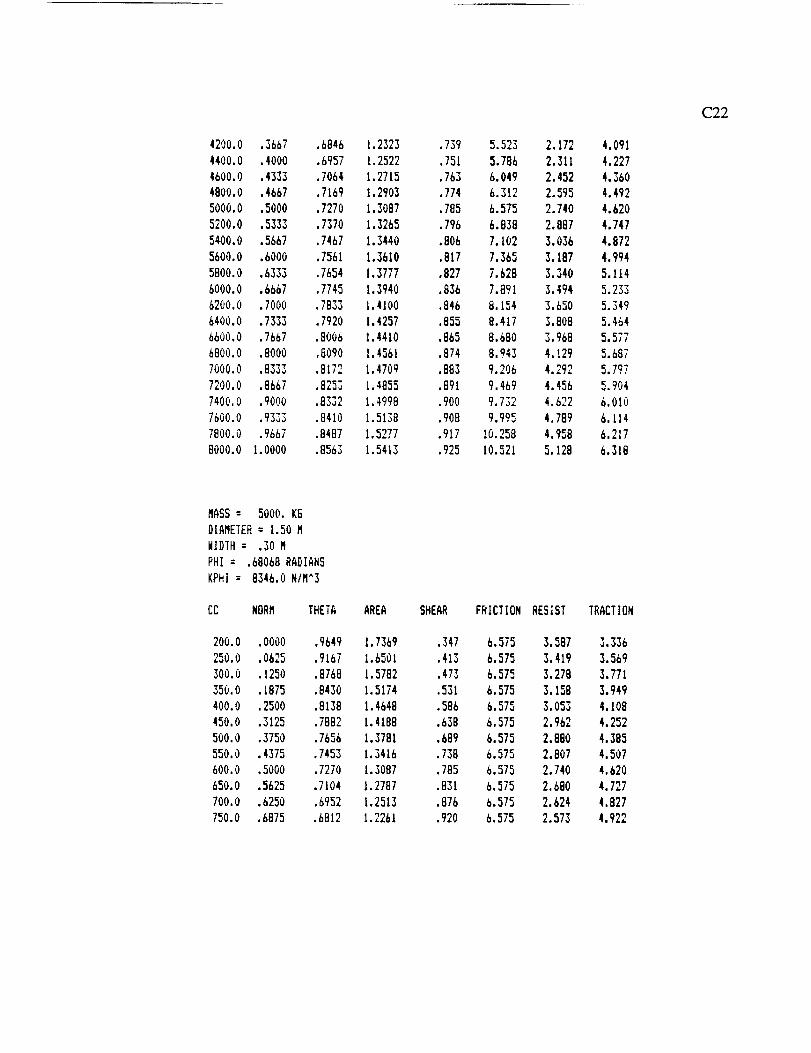
42O0.0 .3667
4400.0 .4000
4600.0 .4333
4800.0 .4667
5000.0 .5000
5200.0 .5333
5400.0 .5667
5600.0 .6000
5800.0 .6333
6000.0 .6667
6200.0 .7000
6400.0 .7333
6600.0 .7667
6800.0 .8000
7000.0 •8333
7200.0 .8667
7400.0 .9000
7500.0 .9333
7800.0 .9667
8000.0 1.0000
.6846
.6957
.7064
.7169
.7270
7370
7467
7561
7654
7745
7833
7920
.8006
.8090
.8172
.8253
.8332
.8410
.8487
.8563
1.2323
1.2522
I•2715
I•2903
1.3087
1.3265
1.3440
1.3610
1.3777
1.3940
1.4100
1.4257
1.4410
1.4561
1.4709
1.4855
1.4998
1.5138
1.5277
1.5413
.739
.751
.763
.774
.785
.796
•806
.817
827
836
846
855
865
874
883
891
.900
.908
.917
.925
5.523
5.786
6.049
5.312
6.575
6.838
7.102
7.365
7.62B
7.891
8.154
8.417
8.680
8.943
9.206
9.469
9.732
9.995
10.258
10.521
2.172
2,311
2.452
2.595
2.740
2.887
3.036
3.187
3.340
3.494
3.680
3.808
3.968
4.129
4.292
4.456
4.622
4.789
4.958
5.128
4.091
4.227
4.360
4.492
4.620
4.747
4.872
4.994
5.114
5.233
5.349
5.464
5.577
5.687
5.797
5.904
6.010
6.114
6.217
6.318
C22
MASS = 5000, KG
DIAMETER= 1.50M
WIDTH= .30 M
PHI = .68068RADIANS
KPHI = 8346.0NIM^3
CC NORM THETA AREA SHEAR
200.0 .0000 .9649 I•7369
250.0 .0625 .9167 1.6501
300.0 .1250 .8768 1.5782
350.0 .1875 .8430 1.5174
400.0 .2500 .8138 1.4648
450.0 .3125 .7882 1.4188
500.0 .3750 .7656 1.3781
550.0 .4375 .7453 1.3416
600.0 .5000 .7270 1.3087
650.0 .5625 .7104 1.2787
700.0 .6250 .6952 1.2513
750.0 .6875 .6812 1.2261
.347
.413
.473
.531
.586
.638
.689
.738
.785
.831
.876
.920
FRICTION
6.575
6.575
6.575
6.575
6.575
6.575
6.575
6.575
6.575
6.575
6.575
6.575
RESIST
3.587
3.419
3.278
3.158
3.053
2.962
2.880
2.807
2.740
2.680
2.624
2.573
TRACTION
3.336
3.569
3.771
3.949
4.108
4.252
4.385
4.507
4.620
4.727
4.827
4.922

MASS= 5000. K5
DIAMETER= 1.50M
WIDTH= .30 M
PHI = .68068RADIANS
KPHI = 8346.0N/M^3
CC NORM THETA AREA SHEAR
200.0 .0000 .9649 1.7369
250.0 .0625 .9167 1.6501
300.0 .1250 .8768 1.5782
350.0 .1875 .8430 1.5174
400.0 .2500 .8138 1.4648
450.0 .3125 .7882 1.4188
500.0 .3750 .7656 1.3781
550.0 .4375 .7453 1.3416
600.0 .5000 .7270 1.3087
650.0 .5625 .7104 1.2787
700.0 .6250 .6952 1.2513
750.0 .6875 .6812 1.2261
800.0 .7500 .6682 1.2028850.0 .8125 .6562 1.1812
900.0 .8750 .6450 1.1611
950.0 .9375 .6345 1.1422
I000.0 1.0000 .6247 1.1245
.347
.413
.473
.531
.586
638
689
738
785
831
876
920
962
1.004
1.045
1.085
1.124
FRICTION RESIST TRACTION
6.575 3.587 3.336
6.575 3.419 3.569
6.575 3.278 3.771
6.575 3.158 3.949
6.575 3.053 4.108
6.575 2.962 4.252
6.575 2.880 4.385
6.575 2.807 4.5i)7
6.575 2.740 4.620
6.575 2.680 4.727
6.575 2.624 4.827
6.575 2.573 4.922
6.575 2.526 5.012
6.575 2.482 5.098
6.575 2.440 5.180
6.575 2.402 5.259
6.575 2.36b 5.334
C23
MASS = 5000,kG
DIAMETER= 1.50M
WIDTH= .30 M
COHESION= 600.0 MIM^2
KC : 12353.0N/M^2
PHI NORM THETA AREA SHEAR
.6109
.619_
.&283
.&370
.6458
.6545
.6632
.6720
.6807
.6894
.6981
.7069
.7156
.7243
.7330
0.0000
.0714
.142B
.2143
.2857
.3571
4285
5000
5714
6428
7143
7857
8571
.9286
1.0000
FRICTION RESIST TRACTION
.7283 1.3109 .787 5.686 2.745 3.728
.7281 1.3106 .786 5.792 2.744 3.834
.7280 1.3103 .786 5.900 2.744 3.942
,7279 1,3100 .786 6,008 2.743 4,052
.7276 1.3098 .786 6.119 2.742 4.162
.7275 1.3095 .786 6.231 2.742 4.275
.7273 1.3092 .786 6.344 2.741 4.388
.7272 1.3089 .785 6.459 2.741 4.504
.7270 1.3087 .785 6.575 2.740 4.620
.7269 1.3084 .785 6.694 2.740 4.739
.7267 1.3081 .785 6.813 2.739 4.859
.7266 1.3079 .785 6.935 2.739 4.981
.7265 1.3076 .785 7.059 2.738 5.105
.7263 1.3074 .784 7.184 2.73B 5.231
• 7262 1.3071 .784 7.311 2.737 5.358

C24
L
m
JiI
o
-- o
: !i I
mm
I II I
°
I
?,?,
i'I
I
I
III
0
_m
Z©
[..T.,©
Zr.TJ
_u
.,<
.,<I:=,

C25

Conclusions and Recommendations
C26
The traction developed from the shear forces acting on the wheel contact area is a
minor factor due to the low cohesion of the lunar soil. The shear contribution to developed
traction is less than 4% for soft soil and less than 11% for firm soil.
The frictional traction force depends only on the total mass of the vehicle and soil
friction angle. This force is not affected by the size or number of wheels.
The most important factor in the net traction force is rolling resistance. The
resistance decreases with greater wheel diameter, but is affected more by increasing overall
mass:
RcCt _2/
R/3 ( C12 )
The effects of rolling resistance are greater in soft soils because of the greater
amount of wheel sinkage. As can be seen in Figure C2, as the vehicle mass increases, the
net traction reaches a maximum and then decreases as rolling resistance becomes
proportionally greater.
The parametric analysis shows the relative effects of vehicle and wheel
characteristics, which will allow optimization of traction performance. Increasing vehicle
mass results in the greatest increase in net traction. However, this also causes the greatest
increase in rolling resistance. Although the increase in traction outweighs the increase in
resistance, vehicle propulsion becomes less efficient as the mass increases. A higher
proportion of energy is used to overcome rolling resistance, and less is used to perform
useful work.
Increasing the wheel diameter increases developed traction and reduces rolling
resistance. The drive unit should use the largest wheel that is practical, considering space
for transport, turning radius, wheel mass, and other factors.

C27
Increasingthetreadwidthresultsin aslight increase in traction due to the increased
surface area and also yields a slight decrease in rolling resistance. However, as mentioned
earlier, a relatively narrow tread has several advantages which outweigh these traction and
resistance benefits.
The drive unit will have the worst traction performance in loose soil. Developed
traction will be relatively low, and rolling resistance will be high due to wheel sinkage.
This performance is typical of the lunar dust layer. However, the cutting force needed to
move the dust will also be relatively low, and the drive unit should have adequate power.
As cuts are made into deeper, firmer soil, the increase in traction and decreasing rolling
resistance will provide more than enough of an increase in net traction for the grader to
excavate the firmer soil.

APPENDIX C: REFERENCES
C28
1. M.G. Bekker, Off-the-Road Locomotion, (The University of Michigan Press, Ann
Arbor: 1960), pp. 25-28.
2. op.cit., p. 28.
3. op. cit., p. 32.
4. op. cit., p. 53.
5. op. cit., pp. 63-65.
6. op. cit., p. 68.
7. Lunar Base Launch and Landing Facility Conceptual Design, (Eagle Engineering,Webster, TX: 1988), p. 2.
8. H.T. McAdams, P.A. Reese, and G. M. Lewandowski, Trafficabilitv and Visibility
Analysis of the Lunar Surface, (Con'ell Aeronautical Laborato_, Buffalo, NY:1971), pp. 63-75.
9. N. Chandra, et al., Design of a Lunar Transportation System, (Florida A&MUniversity/FSU College of Engineering, TaUahassee: 1989), p. 7.
10. John Graf, "Construction Operations for an Early Lunar Base," in Engineering.Construction. and Ope_rations in Space. Stewart W. Johnson and John P. Wetzel,eds., (American Society of Civil Engineers, New York: 1988), pp. 196-198.
11. J.L. Merriam, Engineering Mechanics, 2nd Edition, Vol. 1, (John Wiley and Sons,New York: 1986), p. 442.

APPENDIX D
Cutting Force, Energy, and Power Calculations
D1

APPENDIX D
Cutting Force, Energy, and Power Calculations
D2
Cutting Force
Four separate equations were used to calculate the force to cut the lunar soil. These
equations are shown below, along with a definition and value for each variable.
Equation 1. From Machines for Moving the Earth, A.N. Zelenin, Russian Translation
Series 33, 1987, p.157.
Pk = 10 C h 1.35 sin3(o_b) (l+2.6L)(1+0.0075a)(l+0.03S)VI.t + _FK + gqy tan(p) + Gi
Where:
Pk = cutting force (N)
C = coefficient of soil cohesion (N/cm 2)
h = depth of cut (cm)
O_b= angle blade makes to direction of motion
L = length of grader blade (cm)
o_ = cutting angle (radians)
S = grader blade thickness (cm)
V = geometric coefficient depending on the wedge angle

(varies from 0.81 to 1.05)
_t = geometric coefficient depending on the cutting conditions
(varies from 0.42 to 4.5)
K = specific resistance to cutting, depends on geometry of cutting tool
(varies from 0.7 to 20)
F = cross-sectional area of the soil chip = hoS (cm 2)
= coefficient which accounts for the increase in K with h
(varies from 1.0 to 2.4)
g = gravitational acceleration (m/s 2)
q = volume of soil in front of blade (m 3) = 0.5 LH2cos(_)
where H=height of blade (m), _=internal angle of friction of the soil
y = soil density (kg/m 3)
p = external angle of friction of the soil (radians)
Gi = weight of the grader blade (N)
D3
The following values were assigned to each of the above variables as an initial
estimate of the grader forces: C = 0.142 N/cm 2, h = 3 cm, Orb = 35", L -- 300 cm, o_ --
27.5 °, S = 10 cm, V = 1.05, I-t = 4.5, K = 20, _ = 2.4, g = 1.635 m/s 2, H=50 cm, _ =
35", y = 2.0 kg/m 3, p = 35*. The resulting grader force was 5.96 kN.

Equation 2. From New Methods for Calculating Resistance to Cutting of Soil,
Balovnev, Rosvuzizdat Publishers, 1963, p. 35.
p
1IsinI°bl t ,4s n2ioclsin2I lIA1LhE cc°t 0 P°l
134
V.I.
Where:
P = horizontal component of the resistance to cutting (metric tons)
_b = angle blade makes to the direction of motion
5 = angle of inclination of the wall
Ctc = cutting angle
A1 = coefficient determined analytically
1- sin(p)cos(2ot c)
A1- 1- sin(p)
L = blade length (m)
h = depth of cut (m)
y = specific weight of soil (metric tons/m 3)
c = coefficient of soil cohesion (metric tons/m 2)
p = angle of internal friction
Po = external pressure on the surface (metric tons/m 2)

D5
The following values were assigned to each of the above variables as an initial
estimate of the grader forces: O_b = 35", 8 = 49", O_c= 27.5", L = 3 m, h = 3 cm, y = 2.0
metric tons/m 3, c = 0.145 metric tons/m 2, p = 35", Po = 0.0 metric tons/m 2. The
resulting grader force was 1.0 kN.

D6
Equation3. From Digging of Soils by Earthmovers with Powered Parts, V.K. Rudnev,
Russian Translation Series 32, 1985, pp. 40.
P = B sin(°0sin(y)+tan(q_)c°s2(y)+tan(¢p)sin2(_')c°s(°0
sin(o_+_l/+19)+tan(¢p)sin (T)cos(o_+_g+19)
2 cos(19)
x[0.5cos(19)cos(_)SrH + sin0,g+19)(cot(_)+cot(o0)SrhH + 0.5cosh (_) ]
Where:
P = cutting force (metric tons)
B = blade length (m)
a = cutting angle (radians)
y = angle blade makes to direction of motion
q_=extemal angle of friction of the soil (radians)
_t = angle of displacement (= _/4 - 19/2)
19= internal angle of friction of the soil (radians)
5R = density of loosened soil (metric tons/m 2)
H = blade height (m)
h = depth of cut (m)
The following values were assigned to each of the above variables as an initial
estimate of the grader forces: B = 3.0 m, c_ = 27.5 °, y = 35*, cp = 35 °, p = 35 °, 8R = 2.0
metric tons/m 2, H = 50 cm, h = 3 cm. The resulting grader force was 49.7 kN.

D7
Equation4. From Digging of Soils by Earthmovers with Powered Parts, V.K. Rudnev,
Russian Translation Series 32, 1985, pp. 38-39.
P = N[sin(o0 sin("/) + tan(_) cos2(y) + tan(_) sin2(7) cos(p0]
Where:
P = cutting force (metric tons)
ot = cutting angle (radians)
7 = angle blade makes to direction of motion
q_= external angle of friction of the soil (radians)
N = component of soil resistance normal to the grader blade
N m
sin(o_+_)
cos(p) R1 + sin('_ls+p) Gch + 0.5 cos(p)T
sin(¢x+_+p) + tan(q_) sin(y) cos(o_+_+p)
T = resistance to shear
T = CB hsin(_)
Gch = weight of the soil chip
co sin(o_+_)
Gch = Brh 8 R sin(_)
R1 = weight of the displaced prism normal to the surface of the chip

sin(_t+19) cos(p)
R1- sin(ot+_) GP r
D8
Gpr = weight of the displaced prism
Gpr= 5RB[r-h sin(Qt+19)]2I2_][.
sin(e-19) sin(e+_) sin2(co/2)
sin(p+_)
Hr=
2 sin(co/2) sin(e)
"tlt= angle of displacement (= rt/4 - 19/2)
i9 = internal angle of friction of the soil (radians)
B = blade length (m)
_R = density of loosened soil (metric tons/m 2)
H = blade height
h = depth of cut
r = blade radius of curvature (m)
e = angle between horizon and cord of the grader blade
co = 2 (e - _)
C = coefficient of soil cohesion (metric tons/m 2)
The following values were assigned to each of the above variables as an initial
estimate of the grader forces: o_ = 27.5", y = 35 °, _ = 35", 19 = 35", B = 3.0 m, 5R = 2.0
metric tons/m 2, H = 50 cm, h = 3 cm, e = 60 °, C = 0.145 metric tons/m 2. The resulting
grader force was 6.08 kN.

199
Although the results of the equations varied, they approximately agreed for shallow
depths of cut. A cutting force of 6 kN was calculated for a depth of cut of 3 cm. This
cutting force is small compared to those experienced on Earth, but is expected due to the
low cohesion of lunar soil, low lunar gravity, and shallow depth of cut. The results of the
force analysis above are summed up in Table D.1 below. The force from Equation 3 is
much larger compared to the results of the other equations because it includes the force
required to move the motor grader itself, as well as the cutting force.
Table D. 1: GRADING FORCE FOR A DEPTH OF CUT OF 3 CM
EQUATION FORCE (kN)1 5.962 0.963 49.744 6.08

D10
A parametric analysis was performed on each equation to determine how sensitive
the cutting force was to each variable. Only seven major factors were varied: the depth of
cut, angle of bite, cutting angle, angle of friction, soil density, soil cohesion, and blade
length. (See Figures D. 1-D.7). The results from Equation 3 are consistently high because
this force includes the force required to move the motor grader.
5o
40
= 30
_ 20
lO
o
0 5 10 15
Depth of Cut (cm)
Equation 1
Equation 2
Equation 3
o Equation 4
Figure D.I: CUTTING FORCE VS DEPTH OF CUT

Dll
60
_. 40
o 30
o
20
50
10
0
20 25 30 35 40 45
Angle of Bite (deg)
Equation 1
Equation 2
Equation 3
Equation 4
Figure D.2: CUTTING FORCE VS ANGLE OF BITE

D12
v
o
O
8O
6O
4O
2O
unl u u ui nu un I.I hi I..I I.I
• | • I • ! • I • l
20 25 30 35 40 45
Cutting Angle (deg)
------m--- Equation 1
---"*"-- Equation 2
Equation 3
Equation 4
Figure D.3: CUTTING FORCE VS CUTTING ANGLE

D13
6o
50
Z 40
30O
2O
10
J
• I " I " I " I " I "
20 25 30 35 40 45 50
Angle of Friction (deg)
Equation 1
"--"*--- Equation 2
Equation 3
Equation 4
Figure D.4: CUTI'ING FORCE VS ANGLE OF FRICTION

D14
6O
5O
..-. 4O
o 30L..
oL_
2O
10
| , .
1.00 1.25 1.50 1.75 2.00 2.25 2.50
Soil Density (kg/mA3)
Equation 1
Equation 2
Equation 3
Equation 4
Figure D.5: CUTTING FORCE VS SOIL DENSITY

D15
6O
50
40
_ 20
10
i i i I i --
' I " I " I ' i " I
0.00 0.25 0.50 0.75 1.00 1.25 1.50
Soil Cohesion (N/cm^2)
Equation 1
Equation 2
Equation 4
Figure D.6: CUTTING FORCE VS SOIL COHESION

D16
6o
50
'°119
o 30
lO
o2.00 2.25 2.50 2.75 3.00 3.25 3.50
Blade Length (m)
Equation 1
--'-*-- Equation 2
Equauon 3
Equation 4
Figure D.7: CUTTING FORCE VS. BLADE LENGTH

Energy Requirments
D17
The energy calculation required the cutting force, road width, blade length and
angle of bite, depth of cut per pass, and total grading depth. The design team did not have
time to perform an optimization analysis to determine how deep the grader must cut, so the
team selected 10 cm (80% of maximum density) as an estimate of the optimum depth. The
energy required to grade per kilometer of road was calculated based on the following
assumptions:
• Road is 8 m wide
• Blade length is 3 m
• Angle of bite is 35*
• Depth of cut is 3 cm
• Total grading depth is 10 cm
• Rate of grading is 2 krn/hr
• Maximum cutting force of 6 kN is constant
It was first necessary to calculate the number of passes required to grade an 8 m
road a depth of 10 cm when the blade is at an angle of 35*.
Number of Passes =Road width Total grading depth
xGrading width Depth of Cut
Number of Passes -8 m 10cm
x - 16 passes3 sin(35) m 3 cm

D18
Theenergyrequiredperkilometerof roadis equalto theforcetimesthe distance
timesthenumberof passes:
E =FdN
E = (6kN)(1,000m)(16) = 96,000kJ
Power Requirements
The power required for the grading process depends on the cutting force and
grading rate. The cutting force is 6 kN and the grading rate is 2 km/hr, so the power is:
P = Fv
P = (6,000 N)(2,000 rn/hr)(lhr/3600 sec) -- 3,333 W
Time Requirments
The time required is equal to the energy divided by the power:
t =E/P
t = 96,000 k J/3,300 W = 8.1 hrs

APPENDIX E
Stress Calculations
E1

E2
APPENDIX E
Stress Calculations
In order to determine the size of the main support beam of the grader, a preliminary
stress calculation was performed. The stress calculation resulted in a value for the section
modulus, which was then used to determine the dimensions of a box beam. A box beam
was selected because of its good torsional strength.
Assuming that the cutting force is concentrated at the center of the blade and the
main support beam is approximately 2 meters off the ground, a maximum moment will be
produced on the beam right above the blade. The moment is equal to the force times the
moment arm.
M =Fd
M = (6,000 N)(2 m) = 12,000 Nm
The allowable stress is equal to the yield stress divided by a safety factor. A safety
factor of 4.0 was assumed since human life would be jeopardized if the machinery failed.
The aluminum alloy, AI-Li 2090, has a yield strength of 496.4 MPa.
(Yall = t5 yield / SF
Gall = 496.4 MPa / 4.0 = 124.1 MPa
The required section modulus for the box beam to ensure failure will not occur is
equal to the maximum moment divided by the allowable stress.
SM = M / (Yall
SM = 12,000 Nm / 124.1 MPa = 9.68 x 10 -5 m 3 (5.91 in.3)

E3
Accordingto theManual of Steel Construction published by the American Institute
of Steel Construction, Inc., a 5" x 5", 1/4" thick box beam has a section modulus of 6.638
in. 3. This beam is sufficient to sustain the applied loading.

APPENDIX F
Grader Assembly Mass Calculations
F1

APPENDIX F
GraderAssemblyMassCalculations
F2
The massof the lunar grader assemblywas estimatedby assuming that the
dimensionsof themajorcomponentsweresimilar to thedimensionsof terrestrialgraders.
The major componentsconsideredin the massestimation are the graderblade, main
supportbeam,positioning ring, ring support,bladeconnectors,two power screws,two
wheelswith titanium rims, and the front end support. Sinceall componentswere not
consideredandthedimensionswereestimated,a25%correctionfactorwasadded.
Blade
The body of the blade is made of AI-Li 2090, which has a density of 2.56 g/cm 3.
The blade is 3 m long, 50 cm high, and 2.5 cm thick. The cutting edge of the blade is
made of Ti-6 A1-4 V, which has a density of 4.42 g/cm 3. The edge is 10 cm high and 5 cm
thick, with a groove for the body of the blade which is 3 cm wide and 5 cm deep.
Mass of blade body = (300 cm)(50 cm)(2.5 cm)(2.56 g/cm 3) = 96 kg
Mass of blade cutting edge = (300 cm)[(10 cm)(5 cm) - (3 cm)(5 cm)] (4.42 g/cm 3)
= 46.4 kg
Total mass of blade = 96 kg + 46 kg -- 142 kg

Main Support Beam
F3
The mass of the main support beam is equal to the area of the beam times the length
times the density of the material. The beam is also made of AI-Li 2090. The area of the
box beam is 29.25 cm 2. The length of the beam is 600 cm.
Mass of beam -- (29.25 cm 2 )(600 cm)(2.56 g/cm 3) = 44.9 kg
Blade Positioning Ring
The blade positioning ring has an outside diameter of 1.2 m, an inside diameter of
1.0 m, and a thickness of 5 cm. The ring is made of titanium.
Mass of ring = _ [(60 cm) 2 - (50 cm) 2] (5 cm) (4.42 g/cm 3) = 76.4 kg
Triangular Ring Support
The triangular ring support is made of aluminum. The base of the support is 1 m
long and the lengths of the two ends are both 3 m. The supports were assumed to be 3 cm
x 3 cm square.
Mass of ring support = (3 cm)(3 cm)[ 100 cm+ (2)(300 cm)](2.56 g/cm 3) = 16.3 kg

Blade Connectors
F4
The blade connectors are aluminum. They were assumed to be rectangular blocks
in order to simplify the calculation. The blocks are 75 cm high, 10 cm wide, and 5 cm
thick.
Mass of connectors = (75 cm)(5 cm)(10 cm)(2.56 g/cm 3) = 19.2 kg
Power Screws
The power screws are made of titanium, are 1.5 m long, and have a diameter of 5
cm. There are two power screws.
Mass of 2 screws = 2(r1:)(2.5 cm)2(150 cm)(4.42 g/cm 3) = 26 kg
Hemispherical Dome Wheels
The dome wheels have an outside radius of 50 cm and a thickness of 5 cm. The
body of the wheel is made of aluminum, but the tread is made of titanium. The tread is 5
cm wide and 2.5 cm thick.

Massof body-- (2)(1/2)(4/3)(/I;)[(50cm)3 - (49.5cm)3](2.56g/cm3) = 39.8kg
Massof rims = (2)(_t/4)[(102.5cm)2 - (1cm)2](5cm)(4.42g/cm3) = 17.6kg
Total massof wheels= 39.8kg + 17.6kg = 57.4kg
F5
Front End Support
The front end support is also a box beam with the same dimensions as the main
support beam, except that it is only 1 m long. It is also made of aluminum.
Mass of front tne support = (100 cm)(29.25 cm2)(2.56 g/cm 3) = 7.5 kg

F6
Total Grader Assembly Mass
The total mass of the grader assembly is 391 kg as shown in Table F.1. The
additional 25% brings this value to 490 kg.
Table F.I: MASS OF THE GRADER ASSEMBLY
COMPONENT MASS (kg)
Grader Blade
Blade Positioning Ring
Blade Connectors (2)
Triangular Ring Support
Power Screws (2)
Main Support Beam
Front End Support
Front Wheels (2)
Titanium Wheel Rims
142
76
20
16
26
45
8
40
18
TOTAL MASS 391

APPENDIX G
Compaction
G1

APPENDIX G
Compaction
G2
Compaction Theory
Soil compaction improves the mechanical properties of the soil in a number of
respects, the most important of which are [1]
1. Soil compressibility is decreased
2. Soil strength increases
3. The permeability is reduced
4. Soil volume change characteristics enhance
A compactor is a self-driven or towed machine that uses one or more methods to
increase the density of a medium. The methods of compaction are static weight, impact
force, kneading action, and vibration [2]. Heavy smooth cylindrical rollers only apply the
static weight, while tamping-foot (see Figure 21) rollers produce both static and kneading
effects. An impact type compactor uses momentum to increase the soil density. Finally, a
dynamic loading (vibration) is obtained by rapidly rotating, eccentrically-mounted weights.
The impact type mechanisms are very similar to the vibrational type. The major difference
between these two is that the impact mechanism and the ground are not in constant touch
(i.e. the mechanism contacts the surface periodically) but the vibrational type never loses
connection with the surface it is compacting. Also, the frequency of the impact systems is
usually below 10 cycles/sec while that for the vibratory systems is as high as 80 cycles/sec
or more [3].
Vibrational forces induce relative motion between the soil particles and they tend to
compact the soil to a higher depth than any other method. For example, the smooth rollers
can compact the soil effectively to a depth of 10-20 cm [4] while the vibratory systems have

G3
aneffectivecompactiondepthbetween50-100cm [5]. Furthermore,vibratorycompactors
areveryeffectivein compactingcohesionlesssoilslike sand[6].
Having too much weight on the soil, even though it results in a faster rate of
compactionandahigherdepthof effectivecompaction,it will tendto crackandloosenthe
top layer of the soil [7]. Generally, using a lightweight vibratory roller or a light to
mediumweightsmoothroller will resultin thebestcompactedsurface[8]. To achievethe
bestcompactionthe normalcontactpressureinducedon the soil must be0.9-1.0of the
elasticlimit of thesoil [9].
Compaction Equations
As mentioned earlier, the best compaction is resulted when the maximum normal
contact pressure on the soil, Omax, is within the following range
Omax-" (0.9 to 1.0) Op, (G1) [9]
where Op is the elastic limit of the soil. For less cohesive soils (sand, sandy loam, dusty),
Crp is 3-7 kgf/cm 2 and that for the medium cohesive soils is 7-12 kgf/cm 2 [10]. Both Gp
and Omax are specified in kgf/cm 2 (kilogram force per centimeter squared).
Smooth Rollcr_
For smooth rollers, Omax is found from Equation G2.
(G2) [11]

Where
C_ = the coefficient of soil deformation, kgf/cm 3,
Ro -- the radius of the roller, cm,
Gr = the total weight on the axle of the roller, kgf, and
Br = the width of the roller, cm.
G4
Cl is calculated using the following equation.
where
C1 = E1/Ds (G3) [11]
E1 "- the static modulus of soil deformation, kgf/cm 2 (for cohesive soil,
E1=150 to 200 kgf/cm 2, and for loose soil this is 100 to 150
kgf/cm2), and
Ds = the diameter of the loading plate, cm (for 5-7 compactors, Ds is 15 to
20 cm).
Vibratory_ Rollers
A rapidly rotating, eccentric-mounted weight will produce a dynamic force which is
computed from Equation G4. (See Figure G 1.)
Where
2 ()2v re0 2F=mq=m - rnrc0
r r
F = the dynamic force produced due to rotation, N,
m = mass of the eccentric weight, kg,
(G4) [121

G5
v = tangentialvelocityof thecenterof gravityof theeccentricweight,m/s,
r = theeccentricityof the rotating mass(the distancefrom the centerof
gravity), m,and
co = the angular velocity of the eccentric weight, rad/s.
The dynamic force produced, F, is added to the static weight of the roller to give us the
total dynamic loading of the vibratory roller.
F
Towing Direction
Figure G 1: VIBRATORY ROLLER
The power required to rotate the eccentric-mounted weight, P, is derived in the
following manner.
2V
P = X(O= Frca = m -- r cor
=my tO= rfJ} mr (it) (G 5)

where
x = torque transmitted by the motor, N-m.
G6
Compaction Calculations
The design team could not find any data on op for regolith and, therefore, assumed
a value of 6 kgf/cm 2 based on the ranges given earlier and soil characteristics of regolith
(for example, its noncohesive behavior). Therefore, using Equation G 1, the range of the
acceptable values for Omax is 5.4-6 kgf/cm 2. Furthermore, the design team assumed a
value of 120 kgf/cm 2 for E:. Finally, the design team assumed a linear relationship (Ds =
2.5 + 0.0025 Gr ) for Ds based on the given guidelines earlier.
Selecting a Gr and R0 and knowing Ds and E:, the design team calculated C1 from
Equation G3 and Omit from Equation G2. In using Equation G2, the design team assumed
a roller width to radius ratio of 3. The design team used the above procedure for various
weights and roller radii to plot curves of Omax versus R0. (See Figure G2). This plot
shows that for a 0.5 m radius roller with a width of 1.5 m and a weight of 5000 kgf (i.e.,
8120 N in the lunar gravitation), Omax is 5.8 kgf/cm 2 which is within the acceptable range
of 5.4-6.0 kgf/cm 2.
Appendix H shows that the mass of the compactor when filled with regolith is
9040kg (14,680 N) or 4520 kg (7340 N) per roller. Since for best compaction 8120 N is
required per roller, another 780 N is needed. Although the volume of the regolith ballast
hopper can be increased to yield an additional 780 N, the design team decided to use a
vibratory mechanism to take advantage of its beneficial features.
Knowing the vibratory force (780 N) and by varying the eccentricity and the mass
of the eccentric weight, the design team used Equation G4 to plot the curves shown in
Figure G3.

11
10 E1 = 120 kgf/cm^2
i 98 Acceptable Range
-, 7, lm 6 .....
4 Gr
Z 3
xm 2
10001 500
0
25 35 45 55 65 75 85 95 lO5 115
RO, crn
G7
Figure G2: MAXIMUM NORMAL PRESSURE VERSUS ROLLER RADIUS
Using Equation G5, the design team calculated the power requirements of the
vibrating mechanism for the same range of parameters used in Figure G3. (See Figure
G4). Figures G3-G4 show that the 780 N required force can be obtained in numerous
combinations of power, mass, eccentricity, and angular velocity. The design team selected
a 15 kg mass, an eccentricity of 0.2 m, and an angular velocity of 16.1 rad/s (154 rpm)
which will need 2.5 kW power per roller to operate. Adding a 10% power increase for
inefficiencies of the motor, the total power requirements for the vibrating system of the
compactor is 5.5 kW (7.4 hp).

G8
(II"Om
ft,
¢D_oo
_m.,n
t-
27
25
23
21
19
17
15
13
11
9
0.10
m-11kg12
15
20
0.15 0.20 0.25 0.30 0.35 0.40 0.45
r, m
Figure G3: ANGULAR VELOCITY VERSUS ECCENTRICITY FOR F=780 N
The design team used Equation C1 to calculate the Main Drive Unit power required
to push the compactor. In this equation
M = 9041 kg,
R =0.5 m,
g = 1.624 m/s 2,
kc = 2.0588 N/m 2,
b = 1.5 m, and
k $ = 8515 N/m 3.
Substituting these values in Equation C1 gives a rolling resistance of 13,200 N.
Multiplying this by the speed of MDU (2 krn/hr) yields the power which equals 7.3 kN.

G9
4.5
4.0
3.5
__ .0
O 2.5
2.0
1.50.10 0.15 0.20 0.25 0.30 0.35 0.40 0.45
r,m
Figure G4: POWER VERSUS ECCENTRICITY FOR F=780 N

APPENDIX G: REFERENCES
GIO
1. S.W. NunnaUy, Managing Construction Equipment (Prentice-Hall, Inc., EnglewoodCliffs, New Jersey: 1977) p. 126.
2. David A. Day, , S.W., ConstructionPublications, New York: 1973) p. 507.
3. Nunnally, p. 129.
4.
°
6.
7.
Equipment Guide ( Wiley-Interscience
T.V. Alekseeva, K.A. Artem'ev, A.A. Bromberg, R.I. Voitsekhovskii, and N.A.
Uryanov, Machines for Earthmoving Work: Theory and Calculations, 3rd edition,Russian Translations Series 30, (A.A Balkema, Rotterdam: 1985), p. 490.
Day, p.518.
Nunnally, p. 140.
Day, pp. 518-519.
8. Day, p.519.
9. Alekseeva, p. 487.
10. Alekseeva, p. 488.
11. Alekseeva, p. 492.
12. Alekseeva, pp. 509-510.

APPENDIX H
Compactor Mass
H1

APPENDIX H
Compactor Mass
H2
The design team estimated the mass of the compactor assembly by estimating the
dimensions of its major components and determining the materials from which these
components are made. The dimensioned drawings are shown in Appendix J. The mass
calculations are shown below for all of the major components.
ROLLERS
MATERIAL:
MASS:
Assumptions:
Ti6 AI4 V
1) the roller is a hollow cylinder with circular plates mounted
on both sides of the cylinder.
2) thickness of the roller walls = 1 cm
Abbreviations: mR = mass of both rollers,
VR = total volume of one roller,
Ro = outer radius of the roller,
Ri = inner radius of the roller,
BR = width of the roller,
t = thickness of the roller, and
p = density.
Analysis:
mR= 2pVR = 2 p [ X (R0 2- Ri 2) BR + 2 X R0 2t)

H3
= 2(4.42g/cm3){ _r[(50cm)2 - (50cm - 1cm)2](150cm)
+ 2_r(50cm)2(lcm)} (lkg/1000 g)
.'. mg = 551k_g.
FRAME
MATERIAL:
MASS:
Assumptions:
A1-Li 2090
1) the frame has a solid rectangular cross section
2) the cross section of the frame is 2 cm x 15cm
Abbreviations: mF = mass of the frame,
VF = total volume of the frame,
L = total length of the frame,
t = thickness of the frame,
w = width of the frame, and
19= density.
Analysis:
L = _(270 cm) + _/(150 cm)2+(155/2 cm) 2 ]
= 878 cm
mF = pVF = ptwL
= (2.56 g/cm3)(2 cm)(15 cm) (878 cm)(l kg/1000 g)
.'. mF = 6.7___.

ROLLER AXLES
H4
MATERIAL:
MASS:
Assumptions:
Ti6 Ah V
1) the axles are hollow cylinders
2) the outer radius of the axle is 5 cm
3) the inner radius of the axle is 3 cm
Abbreviations: mA -- mass of both miler axles,
VA = total volume of the miler axles,
Ro = outer radius of the miler axles,
Ri = inner radius of the roller axles,
L = length of the miler axles, and
p = density.
Analysis:
mA = 2 pVA = 2 p _ ( R02 - Ri 2 ) L
= 2(4.42 g/cm 3 ) (_) [(5 cm) 2 - (3 cm)Zl(150 cm)
x (lkg/1000 g)
.'. mA = 67 kg.
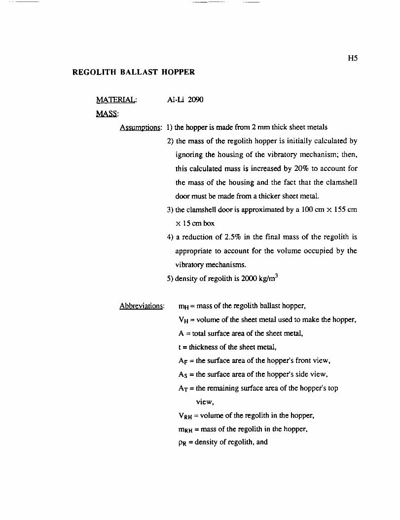
REGOLITH BALLAST HOPPER
H5
MATERIAL:
MASS:
Assumptions:
A1-Li 2090
1) the hopper is made from 2 mm thick sheet metals
2) the mass of the regolith hopper is initially calculated by
ignoring the housing of the vibratory mechanism; then,
this calculated mass is increased by 20% to account for
the mass of the housing and the fact that the clamshell
door must be made from a thicker sheet metal.
3) the clamshell door is approximated by a 100 cm x 155 cm
X 15 cm box
4) a reduction of 2.5% in the final mass of the regolith is
appropriate to account for the volume occupied by the
vibratory mechanisms.
5) density of regolith is 2000 kg/m 3
Abbreviations: mH = mass of the regolith ballast hopper,
VH = volume of the sheet metal used to make the hopper,
A = total surface area of the sheet metal,
t = thickness of the sheet metal,
AF = the surface area of the hopper's front view,
As = the surface area of the hopper's side view,
AT = the remaining surface area of the hopper's top
view,
VRH = volume of the regolith in the hopper,
mRH = mass of the regolith in the hopper,
PR = density of regolith, and

p = densityof thesheetmetal.
H6
Analysis:
At= = 70 cm(300 cm)+ 70 cm (100 cm ) + 2{(1/2)(5 cm)(50 cm)
+ (50 cm)(5 cm) + [(50 cm)(50 cm) - (1/4)(_)(50 cm)21 }
= 29,040 cm 2
As = { 15 cm + (1/4)(2g)(50 cm) + [(50 cm) 2 + (5 cm)2] °'5 + 70}
× (155 cm)
= 33,140 cm 2
AT = (100 cm)(155 cm)
= 15,500 cm 2
mH = pVH = p A t = p (2AF + 2As + AT) t
= (2.56 g/cm 3 )[2(29,040 cm 2) + 2(33,140 cm 2)
+ (15,500 cm2)](0.2 cm)(lkg/1000 g)
= 72 kg
mH = 72 kg + 0.2 (72 kg)
.'. mH=86_ _.
The design team calculated the mass of regolith contained in the hopper in the
following manner.
VRH = {3 m(0.9 m) + 2 m(0.05 m) + 0.5 m(1 m)
+ 0.15 m(1 m) + 2(1/2)(0.5 m)(0.05 m)
+ 2[(0.5 m)(0.5 m)- (1/4)(_)(0.5)21} (1.55 m)
= 5.55 m 3

mRH= pRVRH = 5.55 m 3 (2000 kg/m 3) = 11,100 kg
H7
The design team reduced the mass of the regolith by 25% to account for the voids between
the regolith particles (since, the density decreases after excavation). Then, the mass was
reduced by 2.5 % for the reasons given earlier.
TOTAL MASS
•". mRH = 8121 kg.
The total mass of the compactor is estimated as follows:
mtotal = mR + mF + mA + mH + mhopper reinforcing ribs
+ 2mvibratory mechanism + mtowing coupling, bearings, fasteners
= 551kg+67kg+67kg+86kg+9kg
+ 2(25 kg) + 10 kg
= 840 kg
To account for the oversimplification of the compactor, the design team decided to
increase the calculated mass by 10%. Therefore, the final estimated mass of the compactor
is
mcompactor = 840 kg + 0.1 (840 kg) = 924 kg
.'. mcomp_mr = 920kg.
When the compactor is filled with regolith the total mass in increased to 9041 kg (14,683 N
in the lunar gravitational field) or 4521 kg (7340 N) per roller.

APPENDIX I
Relevant Patents
Grader Control (3,786,871) ........................................................... 2
Conveyorized Motor Grader Blade With Retractable End Bits(3,777,822) .......................................................................... 5
Fine Grading Device For Rubber Tire Road Grader (3,693,722) ................. 8
Road Cutting Machine With Laterally Extensible Drum and Method(3,767,262) ......................................................................... 13
Motor Grader With Saddle Mounted to Transverse Pin on MainFrame (4,696,350) ................................................................ 17
Excavating and Grading Machine With Adjustable Rotary CuttingHead (3,841,006) .................................................................. 22
Small Sub-Grader (3,999,314) ....................................................... 24
I1

PRECEDING PAGE BLANK NOT FILM,':D
I2
United States Patent Clg_Lonl et el.
tl,! 3,786,871
1451 Jan. 22, 1974
3.30).319 211967
3.495.663 _11970
3.313.281 911967
3,G26.638 3/1962
2.961.?13 1111q60
3,434.101 ?/1969
_t.4|lK56d 1211969
3,22q,391 1/1966
J.694.426 211970
154i GRADER CONTROl.
|75| leventorl: C,_Wlpr Ir Lamg, Monroe; Denlt_ !.
Ihmm., Kirkland; Floyd C. Jolmm_
Seattle. aft of Wub.
[731 ,_ ._Pllf:.' _.r_-Llme lnc_ _,Vo_, nwlle. Wish.
[2;'1 Filed: JId_ 26, 19"71
[21 | App|. No.: 165,9'73
[S?[ U.S. CL .................................. 172/4-4. |72/793
I $ I ] lat. CI ................................................ [O?J 3/"/6
[38] Field el Sealrch.... 172/4._; 94146 AE; 230/202.
230/203; 299/I
1561 Rdm.am Cited
UNITED STATES PATENTS
RivmM ............................... 17214.$
kholl et id .......................... 172/4.$
Fiaher .................................. 172/4.$
H|yMf et I_ ........................ 172/4.$
Ik_.t e¢ 81......................... 172/4.$
Iheil_tfth el |l .................... 17214.3
Pml_ el Id ............................ 17214.3IlrlilblTCh It II .................... 1"/214.3
Sludeblkl_t .......................... | _]/d._
3,3_'4.291 111971 Rollel_ el d ........................ 17214.5
PrJmory _mmmt.r--Roben E. Pulfrey
AJ_ruMmt EJmmlne_--R. T. Radar
A.orr, z_, A/*.m. ¢v rim--Richard W. Seed et al.
1371 AI_'rRACT
A cop.tml system foe u road iFader adapted to main-
tam the workinl ,,,,tie of the Ip'udtr blade in I preset
datum plane io al to _..abli_ a unilb."m IFaded condi-
tim* of Ow surface worked by the blade, regardless of
the inclinatioa a_mu_ by the me'tot Irlder or the
relaUve anlruJar poaufmn of the _ .:tell. The system
includes grade _mor means mounted adjacent one
end of tl_ blade to follow a pre.4ude_ed grade datum,
_ll,llmll meanl iltoUnled m (]and relation with the
blade/or keep_n I the blade at I ptedeterl_ined slope
with rotar? potitioa _nmn I me.Juts mout_ted mt the
blade |ul_ontnJ runE 0r circle to detect the relative
angular pmilion of the blade, and longitudinal grade
anlle lenlln I meslu with rotary I_SitiOfl scIrtsine
maims for allCTtll I the ¢Olttro[ lil[l_aJs tO ¢0mpcnll.lle
for grade ¢hat1_ and fota_ poliuon of the blade
I _ it Dr'**tug Ir_m
,i
ORIGINAL PAGE IS
OF POOR QUALITY

]3
PATENTEO,_N22Tg74
91(_ I OF 3
3.786,871
M,
INVENTORS
_r.u_ar.-'^R_" F'. LONG - - -DENNIS L. REESEFLOYD C. JOHNSON
ATTORNfYS
OF FOOR QU/_L,_Ty

I4
PAILN1FU-'A__219r_
_I£ET 2 _ 3
3.786.871
FXG. 2 _,_- _- _2 __
FIG. 312 16
I0
FIG.
10
GEORGE E. LONGDENNIS L. REESEFLOYD G. JOHNSON
INVENTDL_
ATTORNEYS
ORIGINAL PAGE IS
OF POOR QUALITY

I5
United States Patent t,9_Stedman et ai.
till 3,777,822
[4_1 Dec. !1, 1973
I-_4) CONVEYQRIZKD MOTOR GBADEII BLADEwrlrH RETRACTABLE END BITS
(75| Inventor: It•beet N. Stmlmlm. ChilJi¢otbe, 1114lobby D. GrltSMlt, Phonnit. Artz.;il_lrt J. Snltllion, Pnonm, II!.
(131 AlaiSnee: C•l_rpmar lrnielm' Co., Paoli•. IIL
122] fihed: M•r. 31. 1972
[211 Appl. No.: 240,167
(521 U.5. CL ..................... IT2/33, 172/63. 172/'782.3714S
(511 Ill. CI ............................................... A01b 3100[5gl Field el Seuek ........................ 1"/2/'784.33.63,
172/200. ?g2: 37145. 112
( S61 |derett_ Cited
UNITED STATES PATENTS
2.64_.633 711953 Jlhm ................................... 1?2FI821.116,38qI 711931 Mober| ................................ 1721331.464_,464 1111923 neatly ................................ 1"/217121.617._38 2/1927 Mowl_ray ............................ 17213)
954.31t 411910 Gttn*_ .......................... 172/712 X
Pr/m_'y E_tamam'--Robet_ E. PuffreyA*:Lunac Faami_,--Staphen C. Pellqrmo
Arlocmty--Donltd J, gcR•e ef al.
(ST[ ABSTIIAC'Jr
A bind• usembly for • motor grader having a powerdhven endieu belt conveyor for forcibly moving mate.hal to one side of the bllKla assembly m provided withcad bits for fa¢ilitatm| operations such as ban• cut.tin|. ditching and the like in wh_h strell m•y be con-centrnh'd at one end of" the blade uscmbly. The end
hie greasy reduce the wear tad risk ofdama|e whichcllt olherBtse occur at the cotua I end of the con-veyor. While the movement of the conveyor leads toprevent _lmminl of maim'flail between the conveyorsad end bit at the c_ttting end of the assembly, tn op-poci_ sit•tartan ptevld8 8t the dischm'le end. To avoidjammtal •t the discharge end. the and biu are retract.• bin whereby o_y the bit st the cu[un| end need bemaintained in the operxUvn pole•loft.
5 Cla_L 5 DrlwlagIrl_lm
ORIG!_:_AL PAGE IS
OF POOR QUALITY

I6
P^rENTEOOzc__tgr_q:K[(T1 CF2
3.777.822
_E'.:=_ _ _f48R . _ _ _4L _.9L Trr
"a6 " ":" _':; v 7- _ _lk
"_" 33" .aa) 3t _ .,,_) "f 42J _37 "41,*4 _3 38 J "_
-==-+'"IEI I I I 11I I_-'"
ORIGINAL PAGE IS
OF pOOR QUALITY

I7
?ATFNTEDOtC_I t91_$H[ET2 Of 2
3.777.822
% ,. /,21\_7 "f _"J" )) 3z .," -_j/_77
L44. 38"_ 8L
--.-- =__ =__
_F.Z.._ ___._,_2
' 34'_
....
77 44".'
I _ '"
"Z
7,4-, __ _ -_
7_ ""7!
ORIGINAL PAGE IS
OF POOR QUALITY

I8
United States PatentBrown
(is( 3,693,722
14s( Scpt. 26, 1972
(s41 FINE GRADING DEVIC£ FOR RUBBERTIRE ROAD GRADER
1?21 (nventm': IUdlmrlL. Ilremi. Chesapeake. Va.
[731 Auql_: |l_lllL L_I. Norfolk. Va.
[221 Filed: Anql. |1, 19"70
[211 App|. No.: 62,917
IS21 U.S.C'L ..................... 172/450 1?2/72, 172/785.
371108
I _ I F Ira. CI .......... £O21 3/76. A01 b 4q/O2. EO2f 3112
ISXl Fkdd o/.'_e_r_b ........... IT2J?f¢$. 779.72. "71.4.$.
172/7R4:37/1011
L56| Rd_ Cltad
UNITED STATES PATENTS
3.490.539 1/1970 Hilm•s et M ................ 172/4.5
3.5611.775 3/1971 Swisher et ai .............. 1723785
I,EII3.404 10/1932 Ronnm| ...................... 172/71
3.423.B59 111969 Swhu'_er ct al ................ 3711011
P_mar7 EJaminer--Robert F_ Puffrey
A_uteat _rnmmtr. _tephen C, Pellegrino
Artornty--Muon, Fenw_ck x. I -m'ence
1571 4BST]IACT
A lradin I blmJe lind I_mdkl rmiry auler Ire sup-
i_rted oo an ausdiary frame transver*.r_ly ,miUI resl_cl
to a Ilrader vehicle from which I1_ f'rm_e _ mpponecl
with the auEer beret connected to the blade for un*tao
ry pivotal movement about I pive( poinl on the frame
between the front o( the blade m the rear _ the4uler in i_nend virUcld alignment with Ihe 'cutting
edge mr the bhKIn W thgl the height o( the auger can
be pavoul|ly televised by hydrauEc cylinder meen_ with
reslX_'_ tO the cumn I edl_ of _ blade for differmll
so_l conditions by pivoUng the huller end blade with
there being • ne|lilpbl4 ven_d dgpilcement of the
cutt0nll edge o( the blade; u matomaucldly operahlt
com$ot means actuates hydrauli'* c_,linden suppomnll
the auxiliary frame from the vehicle in reslmmm to
SilFnals from a |aide line extending _on| the ixl_h of
movement of the vehicle for m_-.ming the culling
edge Of the blade at a given elevntu_n With I_S_t tO
the guide lime relirdleu of the betlht o( the auger
with r_spect to the cutting edle o(, the blade u ad-
justed by the opcratoe" for diffenn| soil conditions.
14 Cl_det_ ? OrlWinll ilium
oRIGINAL PAGE IS
OF pOOR QUALITY

19
PATOfrLqis[r2s sr_SLEET% OF"4
3.693.722
0
_oe, ee'r L. E_=ZOWN
ATTORNE'_',S
OP,IGINAL PAGE IS
OF POOR QUALITY

PRECEDING PAGE BLANK NOT FILMED• • v • .
IIO
SXEET2 _ 43.693.722
i
ORIGINAL PAGE IS
OF POOR QUALITY

III
PAT[NT[Os[rz'6mzz
SX[ET3 OF43.693.722
ORIGINAL PAGE IS
OF pOOR QUALITY

I12
I_ATDIT_s(r26 tart
_43.693.722
0 o
ORIGINAL PAGE IS
OF POOR QUALITY

I13
United States Patent [i,i
PenUth
[t,I 3,767,262
{4_[ Oct. 2.3, 1973
[$4l IIOAD CUTTING MACHINIg Wlr'rH
LATERALLY [XTENSIIIL Ir DRUM AND
M ETHOD
[ 751 Inventor: Gcw_ld It. O. Pt, mlt_, She•aid.
EnsJanct
[731 Aslillnee: Gr_mmi_MeeblbmCL, Llmil_,
D ur'e.am. En_tmt
[22] Filed: Nay. l?, 1971
(21| Appl: No.: 199.677
1521 U.S. CL ...................... 19_1/t0, t72/122. 299t39
1511 Ira. CI. .......................................... £01c Die9[_|| Field el _ortk ............. _99139...tl. 10: $1/176;
371117.S; q41_O: 1721122
[ 56 | llel•r_nm Cited
UNITED STATES PATENTS
1.883.404 |QII932 Ronnm I ............... 2q¢t3i X
2.Jg"tJ4qb 511937 Hmr|rsve el •1 ............ 2¢ltq_q X
) 560,Q$0 3JIq71 I.ocg woml ............................ 2qQ/3q
Primary E.lammer--Ern•t¢ R, Purer
Attort_ry--C. Yatdley Chttttck •t al.
[ 571 AIJSTItACT
A machine for rolwovm¢ • worn rocd It•trace com-
prtte• 8 ¢hlUmLS Oft whgh It supporu_ • rotary drwm
armed with ¢uuInll picks. TO make po_tbl• • redltc-
bolt in the tnncr tad|at of It• •rcuofdt path gut out by
the rouJry drum, the drum ts tr•Verlmlale into • Ira•t*
tmn lymg ouUade the ground plat. o( the m•ct_mc u
defined by th• wheels on which the machine it stJp-
pOC_d_l for movement.
7 Cl•lm_ 4 OrswlSll glllUrtUJ
ORIGt_4AL PAGE IS
OF POOR QUALITy

I14
PAT[NT[OOCt:,3 maSIt[IT 2.r,F3
3.767:262

I15
PATENI[Ooct23 mTzSHIFT2 ff 3
3,7671262
F/G2.

I16
PATEHT[Doct23 m3SH[ET 3 OF 3
3.767.262
0 \ ......

I17
United States Patent t,,Jltuhter et M.
Pml Patent Number:. 4,696,3S0
[45] Date o( Patent:. Sep. 29. 1987
[_t]" MOTOR GilADI_I _ SADDIIrMO_ _ TIIAJqSV]D_E PIN ON MAIN
[79] InveatoN: Mm-aa L. ihdtm_, Dt_Jm ,4.Ikmq_:. Dm_ W, Sm_mL *JJm"Du_lm. low,
Amilguc_ l]tm_ • C,mqtamy, MotiM. IlL
API_ ?4o.: "tie,eta
F'fled: _ IS. 1_
Imt. ¢_.' ............................ mnZf &tie
U-$. C2, ................ 172//9_ 371101 1_172/753: 210/'7(d_, 40313117
FIll d Sem_ ..... 172/'/76. 7|L 759, 791.
172/793. 795, 796, 797, 710. 712., 7t). 714, 7|S,TIlL 7117,TEL 79Q, 792. 794. 790, ?99, 753;
4031317. 3ti; III0/I I. 23S: 2110/'/60:. 371108 P,.2.11.234. 235, 256. DIG I$
Itm_mcm Qtml
U.S. PATF.N'r _F-N'YS
_?.$l_t 411941 _ el It_ 172/711-- --l.l$I. 13]'-10/I t$1--_Mme-'-" 403/]11
J-127.4;.1 &/IN7 llmmkmm'y_,_M. _ l?2/'/9JX3.413.354 12,/|qNMI l*_lm_ __ 40,1/311X
f?31
l:*]
(_rrlp21
lSt|
[S6l
],4S4.110 ?/Iq_l I HIj'tMf ............. I?Z.eTq3• ]..$1MkJ6) 10./1974kSq_ ......... IT_LngJ
4.496.261 i/19|5 Coh_ .1 tL ............ '03/311 X
PnmmV E._num,r--Richard T, $touffet
I_ Aas'rRAcr
A tWdle a_nml_Jm_ fo_ me is • motor Ilntder Imvxnll• fot_-mKl-*.q utmdm| mare framc campmm| _a
_ poftlee lutvinll • _1¥ Iomlptudh_d _teadin¢I_ formm| • fm'wu_d f_| _ • n_ar (,m:xnll. Thefl_nlp have • learn'Idly ve_xai or_ttlttton. The marefnm_ h_m Ct..-uand *a;,m_f put, _d_y moun ,-_ rams-verst.iy m the mma frLq_ m IOnlptUclinal smr..ed apartretatma_p. TI_ fro'mini ft_a I o( the mddk upperpo_m_ _'mdlm the mma frame ud is fmably mmmtedm ol_te mda m"the tim i_a. im like mnm_. tlut _at
facia| m'add_ tlut eutm frame ted U fta,_y mmmtedm _lm_te e_tt of the mmnd m. Th_ mk_k fur_
ia¢lvdes • k)v_ portma ml(td_| dse mare frame aadfLIJ_iy motlated t_ _ f•cmi[. Tim mare fr•me hat •pltm_icy of _ (ormed ia t"_nrv, _ _ ofthe un frame m loelpmdi,md _*eed apart rehmomdupf_' I_ttably recmv_a| iawltrdly _ lamdmp
formed ea the ftcmlp.
4 Clatm_ S Dm_ F'_m_
ORIGINAL PAGE IS
OF POOR QUALITY

I18
U.S. Patent se_ 29, 19g7 sh_ ! of 4 4,696,350
\
ORIGINAL PAGE ISOF POOR QUALITY

I19
U.S. Patent se_ 29, 1987 Sheet2 of4 4,696,350
158 .158
/l_ i l /4

I20
U.S. Patent sep, 29, 1987 Sheet 3 of 4 4,696,350

I21
U.S. Patent Se_ 29,19s7 Sheet4 of 4 4,696,350

I22
United States Patent t,_
Mironov el al.
I nxl 3,841,006
f451 Oct. l.q, 1974
1541 [XCAVATIN(; AND (+'RADING MACHINE
WITH ADJUSTABLE ROTARY CU'I'I'ING
HEAD
176] Invenlu_: Ivaa Ammmvldl Mtrmmv.
Inslllutskaya ulitsa, lb. kv. 55;
VIIdbtlv lollfovkh NIItllbk
Insltlulskaya ulitla, IO, kv. I I. both
of Pushklno Moskovskoi oblallK
Vuhmtln DmlIHevk'h Khelcv. ulilsu
T_¢nlra|naya. 5, Moskov_kaya
ohtasL poseiok Mamontovskaya. allof U.S.S R.
[22l Rlcd: MIr. 1. 19"I3
1211 Appl. No.; 337.196
{521 U.S. CL ................................. 3?11011 IlL 3"7Ilxg
1511 Im. Cl ................................................ E02I 31111
15_I Fk4d el.tiem'¢h ...... 3711149, 108; 17211107. 1403,
17211404
1561 Relerences Cited
UNITED STAVES PATENTS
2.402,q76 "//I q4t_ Olson .............................. I ?21NO3 X
2Jl4?,I 34 MIIq$1_ Slate ................................... 21411311
3.3?$.M711 4119_11 Dom ............................... I ?21NU? X
3.4tKl.$)q IIIg?O Hllmes ct al ..................... _?/IOl X
3.65 I._RII 111tl72 Hanson ............................. 371111N R
3,btI].52 _. allU72 ROUlI4:IIW e! mI.................. ]TIIIl_ X
t.b*l,t,7 _-+- WILT. _ llr+m'n .................. JTIIUX X
Prlmu_ + E._uminer--Clifford D, Crowder
Attorney. ,4Rrnt. ue F+rm--Holman ,t. Stem
1571 A_TRACT
An tmprovelr_nl in an excavating and Ir'atlin| ma.
chir.c with a power-driven active culllflg head which
rotates durinll the procels of excavulton+ More spccnfi.
oilily, the, improvement relays to the tusl_nston of the
rotary cutting head in which the frame of the cuttnng
head comprises a juxtaposition of three meml_er
frame. The tint meml_r frame of the cuIIIn I head
r_lidly contacts to the fntme of a self-_opelled ch_.
sis of the machinc. Th_ mond memher frame il con.
necled It.) Ihe fir,,tl frame by an axle ptvol arran|cd co-
axially with the longitudinal axis of the frame of Ihe
chas_s and is capable of lUmln[I about this pivot h)
meam of a hytlraulic c_/linder. The third member
frame of the cutt0n| head is connected tO Ihe second
member frame by an axial pivot arranged at nlhl an-
gles to the longitudinal a_tls of the ch_.tsis frame and is
hnked up with hydraulic cyJilxJeP! 14cry|flU tO turn this
member frame about the pivOI which connectl it to
the p=eceeding second member frame. The axles of
boIh plVOll are tubular to p_l through their bores a
power Iranzmimon for Impartlnll motion Io the rotary
cuttlft| head.
I c_: 2D..._., rip..
f
<3
<0
<
4_
e, O__-/G
I "I_ i -_6 ,,/
• _. /_
>
7/
ORIGINAL PAGE IS
OF POOR QUALITY

I23
PATENIEOocTx5197q 3,841.006
E
<I
I,
o<
o<L
S
rsu
_1 _ I_r_J
>
FIG. 2I6
_,o,zJ,2_20
D N
F/G I

I24
United States Patent t,+lMiller et 81.
IIII 3,999,3 !41451 Dec. 28, 1976
1541 SMALL SUKIADtll
1751 Inven_ _ J. Miler:. CliJm P. Mtr.hods or McHear?. IlL
1731 A_lilnee: MImr Fm'lMm Cm,.,,i_. Mcl.tlenl_.IIL
1221 Filed: No_. S. 19"/5
1211 Appl. No.: 629,01J
1521 U.S. CL ................................. 37tIM Ill 172/4:37+I)1G. 20; 404/84:172/26
1511 Im, CL T ........................................... I_llr $/N
15NI IrlMM d _ ........ 371101 R, 101 A, DIll. 4,37115.2U; 17214+5.4.26. 779. 803. 104,807;
4041114
1561 _ CIVIl
UNITED S'l'A'n_ PATENTS
3.OZq.?lO 4llqNb2
._.423J$9 lll'_q3,452.461 11194W3.NJ6.1127 911971).637,1126 1119123.74q.JIRI 711Y7)J.1122.751 ?IlY?4J.914.0_4 IUIlY?S
|leI ............................... 104114Ray. Jr............................. 172110,1Sv,.dwr. Jr. el al............ 404/114 XHiu_a ......................... ]?llOl XMiler ot IJI. .................... 404184S_ ............................... 17214.5
Sm_tll ................................. 404114Wuteml .................... 1721104 XGu¢'rm ......................... MNII4
FOREIGN PATENTS OR APPLICATIONS
24,3.7o? $11_$ A_tm ............................. 1721|03
I.,lliJ|3 7,,'197 't Umf_l Itbllla_ ........... 404til4
F-_am_.r--E H. Fi,'kh,_A#;om¢7, Agenr, or Finn--_ K, "rhomm
1571 AISTRACT
T1be mtatin 8 cutlin I woId • eub-IPmc_r is adjmmblymmm.,.,4 _ the IMml ot Um fnune of _e ma-
chine vpon a Iool mp1_rt m 8 nImer which lmlawscimnIm im Fade from chili, in slope and whichmimizm me m.%ace d cl, ml_ m dope upoa theIm_ o/tl_ toot TI_ ummmm_ print uis for p'a_cNU_ of the l_ IppoN m IocIt_ at in im_rmediauIX_t on thi mare fru_. _t_le the cmUnl toot. i
amxiI_l mi,m me_ mml ImxmmI ,rare mo_.,,_ on ,m
indelNmlem pi_ --- for aol_ ,_tml tl_ _44
I_y oil one _ o( _ m.lun fnu_t. Any
_ml Immn_l Uw m _oI rapport om tl_ mmwe__ _l_Ry m _U_ e_b _dMck anm _t _ltet the dOl_
Ihll UI chlnIe in _ mid Id_ ilIil_M o( Ibe Ioo_ ilThe I I tool ii iI_ _
en_,ly independent o¢ tlx _ d_viatmm lad IM "
Iooi i nulmuW_d in | deled iMau_ it idl timelL
18
o,
,__'_-_-/. i10 "_"
(. ORIG1NAL PAGE ISOF POOR QUALITY

I25
U.S. Patent Dec. 28. 1976 Sheet I or 3 3,999,3 14
FIG. 1
27
b
ORIGINAL PAGE IS
OF POOR QUALITY

I26
U.S. Patent _ 28, t97_i sh_t 2 of 3 3,999,314
FIG. 3 4.,
114
FIG. 4 _ ,42 4o
_ ras?-'=====-_ i lll :t ""
FIG. 5 FIG. 6
70ti,6,
96 "-7'4

I27
U.S. Patent 0,,¢. 28, 1976 Sheet_ of 3 3,999,314
o

APPENDIX J
Dimensioned Drawings
J1

J2
0.3m
0.65 m
0.05 m
1.75 m
0.875 rn
III Ii II Iil
'_ 1.25 m =i _!
I
1.8 m
0.1 m
III II
_' -'1°55 ml_-o_ P o__.___l / L_=_ I.
1.2 m __
o._m-_ t0.05
e-0.85 m_ 0.1 m !3.3m
4 4.15m _--

J3
L
_ m
i
E0
c_
i!
'r i
Ft
0
_r

J4
0
_Ed
E
[_

r-
I
1.0m
1.2 m
3m
D
i-"D
Om
0.05 m
1.5 m Long

J6
I
0.5m
m
0.25 m
lm2.5m
m

$7
[20.002 m
T|o.9m IT T L ;'T',
0.05 m ¥ rI
3m
_I--1.1 m---_
!
,e----- 1.55 m ----=,-
I I
I I

.]'8
1.6m |Ii
'l||q
I° 2.1 m d
L2.7 m