Concept of Operations Florida Department of Transportation...
44
Concept of Operations Florida Department of Transportation Florida Highway Patrol Computer-aided Dispatch Data in SunGuide Software January 6, 2009 Final – Version 3.1 Prepared for: Florida Department of Transportation Traffic Engineering and Operations Office Intelligent Transportation Systems Section 605 Suwannee Street, M.S. 90 Tallahassee, Florida 32399-0450 (850) 410-5600
-
Upload
duongduong -
Category
Documents
-
view
224 -
download
0
Transcript of Concept of Operations Florida Department of Transportation...
Concept of Operations Florida Department of Transportation Florida Highway Patrol Computer-aided Dispatch Data in SunGuide Software January 6, 2009 Final – Version 3.1
Prepared for: Florida Department of Transportation Traffic Engineering and Operations Office Intelligent Transportation Systems Section 605 Suwannee Street, M.S. 90 Tallahassee, Florida 32399-0450 (850) 410-5600
Final: Version 3.1 - January 6, 2009 i
DOCUMENT CONTROL PANEL File Name: 090106 FHP CAD Interface Concept of Operations_v3_1_Final.doc
File Location: W:\C8I75\Assign 4 - SunGuide\FHP CAD Interface ConOps\090106 FHP CAD Interface Concept of Operations_v3_1_Final.doc
Deliverable Number:
Version Number: Version 3.1 - Final
Name Date Created By: Trey Tillander, FDOT 3/28/07
Reviewed By: David Chang, PBS&J 3/28/07
Trey Tillander, FDOT 8/7/08
Carlos Bonilla, Peter Vega, Steve Corbin, Michael Smith, Manuel Fontan, Terry Hensley, Trey Tillander, FDOT
8/25/08
Steve Williams, FHP 8/25/08
Walt Townsend, Siemens 8/25/08
Steve Dellenback, SwRI 8/25/08
Modified By: TJ Hapney, PBS&J 3/28/07
John Hope, PBS&J 8/7/08
John Hope, PBS&J 8/25/08
TJ Hapney, PBS&J 8/27/08
John Hope, PBS&J 12/3/08
John Hope, PBS&J 12/18/08
John Hope, PBS&J 1/5/09
TJ Hapney, PBS&J 1/6/09
Completed by: TJ Hapney, PBS&J 1/6/09

Final: Version 3.1 - January 6, 2009 ii
Table of Contents 1. Overview .................................................................................................................. 1
1.1 Identification ...................................................................................................... 1 1.2 Document Overview .......................................................................................... 1 1.3 System Overview .............................................................................................. 2
2. References ............................................................................................................... 4 3. Current System Situation ......................................................................................... 5
3.1 Background, Objectives, and Scope ................................................................. 5 3.2 Operational Constraints .................................................................................... 6 3.3 Description of the Current System or Situation ................................................. 6 3.4 User Profiles ................................................................................................... 10 3.5 Support Environment ...................................................................................... 10
4. Justification and Nature of the Changes ................................................................ 11 4.1 Justification for Changes ................................................................................. 11 4.2 Description of the Desired Changes ............................................................... 13 4.3 Change Priorities ............................................................................................ 14 4.4 Changes Considered (Not Included) ............................................................... 14 4.5 Assumptions and Constraints ......................................................................... 14
5. Concepts for the Proposed System ........................................................................ 15 5.1 Background, Objectives, and Scope ............................................................... 15 5.2 Operational Policies and Constraints .............................................................. 16 5.3 Description of the Proposed System ............................................................... 16 5.4 Modes of Operation ........................................................................................ 24 5.5 User Involvement and Interaction ................................................................... 24 5.6 Support Environment ...................................................................................... 25
6. Operational Scenarios ............................................................................................ 25 7. Summary of Impacts .............................................................................................. 25 8. Analysis of the Proposed System ........................................................................... 26 9. Notes ...................................................................................................................... 27
Final: Version 3.1 - January 6, 2009 iii
List of Figures Figure 1: SunGuide Software Release 4.x high-level architecture. ................................. 3 Figure 2: Map Comparing the FHP RCC and FDOT District Jurisdictions. ...................... 6 Figure 3: Start page of FHP Traffic Incident Web site. .................................................... 7 Figure 4: Regional (Troop) Crash Report. ....................................................................... 8 Figure 5: Incident Detail Screen displayed via Google Maps. ......................................... 8 Figure 6: FHP CAD Data Viewer. .................................................................................... 9 Figure 7: Locating the FHP CAD incident via Google Maps popup. .............................. 10 Figure 8: FDOT Incident Duration Timeline for Statewide Performance Measures. ...... 12 Figure 9: ITS WAN Statewide Deployment ................................................................... 17 Figure 10: FHP CAD Interface Implementation Concept ............................................... 18 Figure 11: Highlighting the Alert List on the right side of the Events List window .......... 19 Figure 12: Example of an FHP CAD alert window ......................................................... 20 Figure 13: Proposed concept for SunGuide Software FHP CAD Interface. ................... 23
Appendices Appendix A: FHP CAD XML Description ...................................................................... A-1 Appendix B: Parsing the FHP CAD Link Element ........................................................ B-1
Final: Version 3.1 - January 6, 2009 iv
List of Acronyms ATIS ................................................................................... Advanced Traveler Information System CAD ........................................................................................................ Computer-Aided Dispatch C2C ......................................................................................................................... Center to Center CCTV ....................................................................................................... Closed Circuit Television ConOps ......................................................................................................... Concept of Operations COTS ...................................................................................................... Commercial Off-the-Shelf CRS .................................................................................................... Conditions Reporting System DMS .............................................................................................................Dynamic Message Sign EM...................................................................................................................... Event Management FDOT .................................................................................... Florida Department of Transportation FHP .............................................................................................................. Florida Highway Patrol FTP ................................................................................................................. File Transfer Protocol GIS ................................................................................................. Geographic Information System GMT ............................................................................................................. Greenwich Mean Time GUI ............................................................................................................ Graphical User Interface IDS .....................................................................................................Incident Detection Subsystem ITS.............................................................................................. Intelligent Transportation Systems IV&V ................................................................................ Independent Verification and Validation LAN .................................................................................................................. Local Area Network QA ........................................................................................................................ Quality Assurance RCC............................................................................................. Regional Communications Center RTMC ....................................................................... Regional Transportation Management Center TERL........................................................................................... Traffic Engineering Research Lab TSS ........................................................................................................... Traffic Sensor Subsystem TMC ......................................................................................... Transportation Management Center WAN ................................................................................................................. Wide Area Network XML ................................................................................................... Extensible Markup Language
Final: Version 3.1 - January 6, 2009
Concept of Operations for Florida Highway Patrol Computer-aided Dispatch Data in SunGuide Software
1. Overview
The first section of the Concept of Operations (ConOps) provides four elements: system identification, overview of the ConOps document, high-level overview of the proposed system, and a brief description of the scope of effort required to take the system from the current state to the final state of deployment. These elements are described in the following sections.
1.1 Identification
This document serves as the ConOps for the Florida Highway Patrol (FHP) Computer-Aided Dispatch (CAD) interface to the Florida Department of Transportation’s (FDOT) SunGuide Software and describes how FHP CAD data is used in the SunGuide Software. This document is supplemental to the SunGuide Software Concept of Operations, dated January 3, 2005. In the event of a conflict between the two documents, this document takes precedence.
1.2 Document Overview
The purpose of this ConOps is to describe how the FHP CAD relates to the SunGuide Software Center-to-Center (C2C) interface and how FHP CAD data is used in SunGuide Software Incident Management, Event Management (EM), Reporting (Performance Measures), graphical user interface (GUI), and Map subsystems. This document describes software system functionality and is not intended to address the communications infrastructure needs between the FHP and the FDOT software systems.
The intended audience for this document is as follows:
• FDOT Intelligent Transportation Systems (ITS) Engineers;
• FDOT Transportation Management Center (TMC) Managers and Operators;
• FHP Dispatch Managers and Operators;
• SunGuide Software Requirements Analysts;
• SunGuide Software Designers and Developers;
• FHP CAD Software Requirements Analysts; and,
• FHP CAD Software Designers and Developers.
Concept of Operations – FHP Computer-aided Dispatch Data in SunGuide Software
Final: Version 3.1 - January 6, 2009 2
This document intends to:
• Communicate user needs and the proposed software system expectations;
• Communicate the SunGuide Software Project Team’s understanding of the user needs and how the software system will meet those needs;
• Build consensus among SunGuide Software users and partners; and,
• Serve as the basis and primary input for the development of the subsequent requirements specifications.
1.3 System Overview
This ConOps may require new functionality in the following existing SunGuide Software subsystems:
• Center-to-Center – This subsystem allows both status and command/control information to be exchanged between TMCs in a system independent fashion. TMCs participate in the C2C environment by developing “plug-ins” which are extensible markup language (XML) interfaces. Status data includes traffic conditions, incident information, and device status information. The command/control capability allows requests to change devices such as dynamic message signs (DMS), closed-circuit television (CCTV), video switch, etc. If FHP CAD data will be routed exclusively through the Incident Detection Subsystem (IDS) and its associated plug-ins, changes to this subsystem may not be required.
• Event Management – This subsystem receives indicators of traffic congestion and recommended solutions (i.e., how traffic devices should be controlled) are generated. The subsystem uses expert system technology to recommend solution scenarios to the operator. After operator approval, the requests to update the traffic devices are sent to the appropriate SunGuide subsystem for implementation. This subsystem also provides for the management, dispatch, and coordination of Road Ranger service patrols and associated data collection. If FHP CAD data will be routed exclusively through the IDS and its associated plug-ins, changes to this subsystem may not be required.
• Reporting (Performance Measures) – This subsystem provides a user-friendly GUI that allows sorting and retrieval of performance measures reports.
• GUI – This subsystem provide access to various other subsystems (e.g., DMS, CCTV, incident management, etc.) using industry standard browser techniques. The approach of a browser implementation provides users the ability to configure their view of the data while providing a flexible user interface. If FHP CAD data will be routed exclusively through the IDS and its associated plug-ins, changes to this subsystem may not be required.
• Map – This subsystem displays primary and secondary roads along with the status information available from the Data Bus. The map connects to the Data Bus and is capable of displaying traffic conditions, incidents, lane closures, and device (e.g., DMS, CCTV) status in real-time. The graphically displayed components are color coded so that trouble spots can be easily identified. The operator is able to pan and zoom the map so
Concept of Operations – FHP Computer-aided Dispatch Data in SunGuide Software
Final: Version 3.1 - January 6, 2009 2
that regions of interest can be expanded or contracted depending on the operator’s needs. Icons are displayed for field equipment locations, incidents, and lane closures; an operator can access the field equipment by selecting the icon. If FHP CAD data will be routed exclusively through the IDS and its associated plug-ins, changes to this subsystem may not be required.
• Database – An Oracle database contains configuration information as well as snapshots of the data that are produced, monitored, and controlled. The data stored includes traffic conditions data (e.g., volume, speed, occupancy, etc.), current device settings (e.g., current message displayed), incident information, etc. If FHP CAD data will be routed exclusively through the IDS and its associated plug-ins, changes to this subsystem may not be required.
• Status Logger – A logging subsystem (for errors and informational messages) within the SunGuide system. If FHP CAD data will be routed exclusively through the IDS and its associated plug-ins, changes to this subsystem may not be required.
• Data Bus – The Data Bus subsystem provides real-time exchange of data between the subsystems of the SunGuide Software System. The Data Bus provides a framework to which processes attach and exchange data with other subsystems. Depositing data to the bus must be done in a structured, common format and extracting data from the Data Bus requires an appropriate privilege level. If FHP CAD data will be routed exclusively through the IDS and its associated plug-ins, changes to this subsystem may not be required.
• Administrative Editor – Allows a system administrator to make configuration additions and changes during and after software installation.
• Incident Detection – Allows SunGuide events to be created or updated from third-party sources, such as VisioPaD1. A separate plug-in is required for different data sources.
1 Note: references to company and/or product names may be trademarks or registered trademarks of their respective owner.
Concept of Operations – FHP Computer-aided Dispatch Data in SunGuide Software
Final: Version 3.1 - January 6, 2009 3
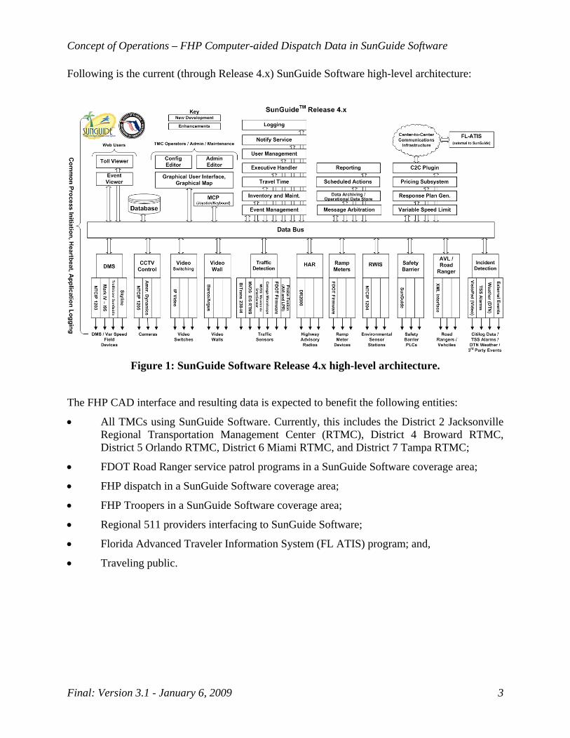
Following is the current (through Release 4.x) SunGuide Software high-level architecture:
Figure 1: SunGuide Software Release 4.x high-level architecture.
The FHP CAD interface and resulting data is expected to benefit the following entities:
• All TMCs using SunGuide Software. Currently, this includes the District 2 Jacksonville Regional Transportation Management Center (RTMC), District 4 Broward RTMC, District 5 Orlando RTMC, District 6 Miami RTMC, and District 7 Tampa RTMC;
• FDOT Road Ranger service patrol programs in a SunGuide Software coverage area;
• FHP dispatch in a SunGuide Software coverage area;
• FHP Troopers in a SunGuide Software coverage area;
• Regional 511 providers interfacing to SunGuide Software;
• Florida Advanced Traveler Information System (FL ATIS) program; and,
• Traveling public.
Concept of Operations – FHP Computer-aided Dispatch Data in SunGuide Software
Final: Version 3.1 - January 6, 2009 4
2. References
The following documents, of the exact issue shown, form a part of this document to the extent specified herein. In the event of a conflict between the documents referenced herein and the contents of this document, this document shall be considered the superseding requirement.
SunGuide Concept of Operations SunGuide-ConOps-1.0.0 January 3, 2005
Florida Department of Transportation Traffic Engineering and Operations Office Intelligent Transportation Systems Section 605 Suwannee Street M.S. 90 Tallahassee, FL 32399-0450 (850) 410-5600
SunGuide-SRS-4.0.1-Draft February 22, 2008
Florida Department of Transportation Traffic Engineering and Operations Office Intelligent Transportation Systems Section 605 Suwannee Street M.S. 90 Tallahassee, FL 32399-0450 (850) 410-5600
Data Elements for Supporting the Florida Department of Transportation CAD 511 Integration Project Version 1.0 April 4, 2005
CTS America
iFlorida CRS-CAD Interface Control Document iFlorida Condition Reporting System Version 1.0 June 24, 2004
IEEE Standard 1512-2006 IEEE Standard for Common Incident Management Message Sets for Use by Emergency Management Centers Approved
IEEE Standards Coordinating Committee 32 on Intelligent Transportation Systems
IEEE Standard 1512.1-2006 IEEE Standard for Common Traffic Incident Management Message Sets for Use by Emergency Management Centers Approved
IEEE Standards Coordinating Committee 32 on Intelligent Transportation Systems
Concept of Operations – FHP Computer-aided Dispatch Data in SunGuide Software
Final: Version 3.1 - January 6, 2009 5
FHP CAD Data Integration in SunGuide Concept of Operations November 16, 2006
SMART SunGuide TMC FDOT District 4 2300 W. Commercial Blvd. Fort Lauderdale, FL 33309
FHP CAD Data Viewer Software Design Document Version 1.0 August 9, 2007
Florida Department of Transportation District 5 719 South Woodland Boulevard DeLand, FL 32720
3. Current System Situation
3.1 Background, Objectives, and Scope
The efficient management of non-recurring incidents is a primary goal of the FDOT. The data required to perform active incident management from the RTMCs is typically gathered from roadway detection infrastructure, roadway cameras, Road Rangers, and calls to the RTMC. Currently, Road Rangers, roadway cameras, and VisioPaD are the only tools that provide the RTMCs with the level of detail in a real-time fashion required to perform active incident management. Unfortunately, these tools are often either overloaded (in high-traffic urban areas) or not available (in rural areas).
FHP works incidents on the majority of the State Roads that the FDOT RTMCs cover. FHP uses a CAD system to collect and manage incident data to and from FHP Troopers in the field.
The primary objectives for an interface between the FHP and the FDOT are to leverage the FHP’s existing infrastructure and processes to:
• Provide real-time data to the FDOT RTMCs for incident notification;
• Provide real-time data to the FDOT RTMCs for incident verification if there are no better means to verify an incident;
• Provide initial incident details in real-time to the FDOT RTMCs so that operators can proceed to verify the incident and then provide incident response, including traveler information dissemination;
• Provide updated incident details in real-time to the FDOT RTMCs for incident management, including traveler information dissemination;
• Reduce effort for the FHP CAD Dispatch to coordinate incidents with an FDOT RTMC;
• Reduce effort for FDOT RTMC Operators to manually input FHP incident details;
• Maintain a consistent FDOT RTMC level of service for incident management;
• Increase efficiency of incident detection, verification, response, and management resulting in improved incident clearance times;
• Maintain a high level of security for FHP CAD traffic incident data used by the FDOT;
• Improve accuracy of incident data; and,
Concept of Operations – FHP Computer-aided Dispatch Data in SunGuide Software
Final: Version 3.1 - January 6, 2009 6
• Improve precision of incident data.
3.2 Operational Constraints The current and near-future SunGuide Software system is hosted and operated in 24 hours-a-day / 7 days-a-week facilities. These are secure facilities with a high level of access control, both physical and computer.
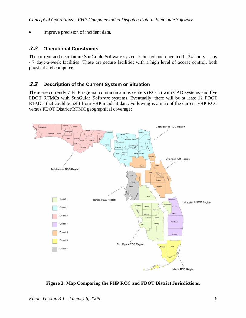
3.3 Description of the Current System or Situation There are currently 7 FHP regional communications centers (RCCs) with CAD systems and five FDOT RTMCs with SunGuide Software systems. Eventually, there will be at least 12 FDOT RTMCs that could benefit from FHP incident data. Following is a map of the current FHP RCC versus FDOT District/RTMC geographical coverage:
Figure 2: Map Comparing the FHP RCC and FDOT District Jurisdictions.
Concept of Operations – FHP Computer-aided Dispatch Data in SunGuide Software
Final: Version 3.1 - January 6, 2009 7
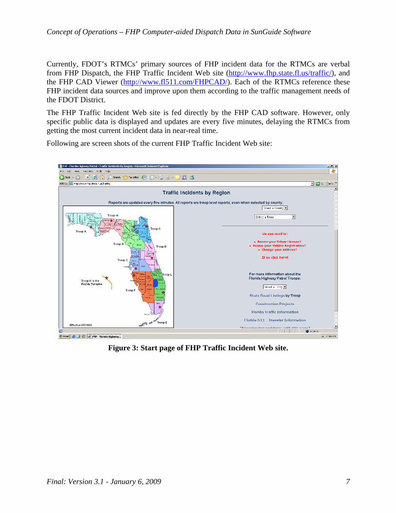
Currently, FDOT’s RTMCs’ primary sources of FHP incident data for the RTMCs are verbal from FHP Dispatch, the FHP Traffic Incident Web site (http://www.fhp.state.fl.us/traffic/), and the FHP CAD Viewer (http://www.fl511.com/FHPCAD/). Each of the RTMCs reference these FHP incident data sources and improve upon them according to the traffic management needs of the FDOT District.
The FHP Traffic Incident Web site is fed directly by the FHP CAD software. However, only specific public data is displayed and updates are every five minutes, delaying the RTMCs from getting the most current incident data in near-real time.
Following are screen shots of the current FHP Traffic Incident Web site:
Figure 3: Start page of FHP Traffic Incident Web site.

Concept of Operations – FHP Computer-aided Dispatch Data in SunGuide Software
Final: Version 3.1 - January 6, 2009 8
Figure 4: Regional (Troop) Crash Report.
Figure 5: Incident Detail Screen displayed via Google Maps.
Concept of Operations – FHP Computer-aided Dispatch Data in SunGuide Software
Final: Version 3.1 - January 6, 2009 9
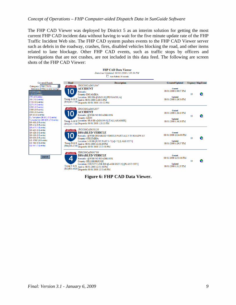
The FHP CAD Viewer was deployed by District 5 as an interim solution for getting the most current FHP CAD incident data without having to wait for the five minute update rate of the FHP Traffic Incident Web site. The FHP CAD system pushes events to the FHP CAD Viewer server such as debris in the roadway, crashes, fires, disabled vehicles blocking the road, and other items related to lane blockage. Other FHP CAD events, such as traffic stops by officers and investigations that are not crashes, are not included in this data feed. The following are screen shots of the FHP CAD Viewer:
Figure 6: FHP CAD Data Viewer.
Concept of Operations – FHP Computer-aided Dispatch Data in SunGuide Software
Final: Version 3.1 - January 6, 2009 10
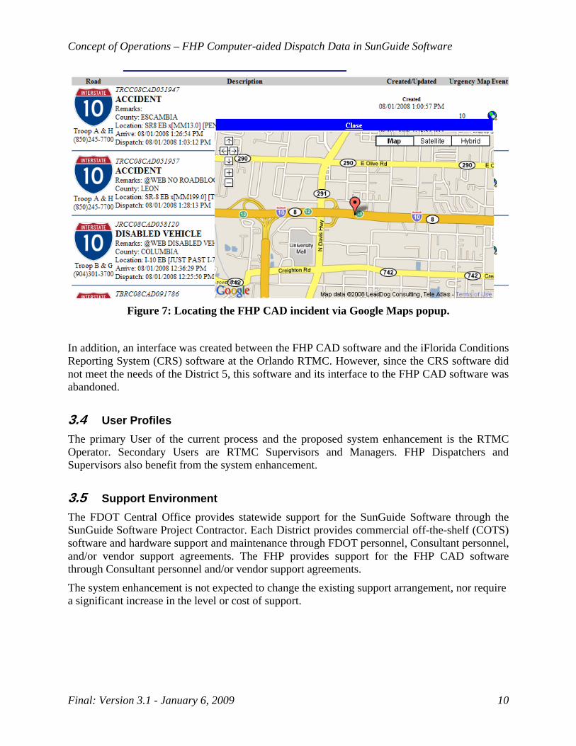
Figure 7: Locating the FHP CAD incident via Google Maps popup.
In addition, an interface was created between the FHP CAD software and the iFlorida Conditions Reporting System (CRS) software at the Orlando RTMC. However, since the CRS software did not meet the needs of the District 5, this software and its interface to the FHP CAD software was abandoned.
3.4 User Profiles The primary User of the current process and the proposed system enhancement is the RTMC Operator. Secondary Users are RTMC Supervisors and Managers. FHP Dispatchers and Supervisors also benefit from the system enhancement.
3.5 Support Environment The FDOT Central Office provides statewide support for the SunGuide Software through the SunGuide Software Project Contractor. Each District provides commercial off-the-shelf (COTS) software and hardware support and maintenance through FDOT personnel, Consultant personnel, and/or vendor support agreements. The FHP provides support for the FHP CAD software through Consultant personnel and/or vendor support agreements.
The system enhancement is not expected to change the existing support arrangement, nor require a significant increase in the level or cost of support.

Concept of Operations – FHP Computer-aided Dispatch Data in SunGuide Software
Final: Version 3.1 - January 6, 2009 11
4. Justification and Nature of the Changes
Time is of the essence during active management of non-recurring incidents. Improved efficiencies, accuracy and precision related to incident data lead to saved time and enhanced safety. A real-time interface for the provision of traffic incident data between FHP and the FDOT reduces clearance times resulting in less congestion and fewer secondary incidents. 4.1 Justification for Changes The current FDOT RTMC tools and processes do not, in all cases, meet the objectives identified in Section 3.1. This is particularly true in three cases. The first case is in a rural area where ITS infrastructure and Road Ranger coverage is not available. This first case may include an emergency recovery scenario where ITS infrastructure is damaged or degraded, but the FHP CAD system is fully operational. The second case is in high traffic, urban areas where a small number of RTMC Operators may manage a very large volume of incidents. In this second case, the ITS infrastructure and resulting data may be available, but the timeliness, accuracy, and/or precision of the incident data may need improvement. The third case is related to recent Road Ranger budget cuts. Without Road Rangers handling and reporting events, FHP CAD event information is even more important. In some cases, the incident data may be real-time, accurate, and precise, but the current tools do not enable a very busy RTMC Operator to efficiently manage the incident at the required level of service.
An automated interface between the FHP CAD system and the SunGuide Software systems in the RTMCs is expected to reduce all parts of the FDOT incident duration – notification time, verification time, response time, and clearance time. The largest percentage decrease is expected to be realized in the notification time component. Where initial notification is by the FHP, replacing the current manual processes with an automated interface reduces the notification time from minutes to seconds.
In addition, some RTMCs strive to attain a goal referred to as the “60 Second Rule”. The goal for these RTMCs is to reduce the combined notification time and verification time to less than 60 seconds on average. This goal is not attainable on a consistent basis without a high level of system automation.
Following is a graphical depiction of the FDOT Incident Duration timeline for statewide performance measures:

Concept of Operations – FHP Computer-aided Dispatch Data in SunGuide Software
Final: Version 3.1 - January 6, 2009 12
Figure 8: FDOT Incident Duration Timeline for Statewide Performance Measures.
Concept of Operations – FHP Computer-aided Dispatch Data in SunGuide Software
Final: Version 3.1 - January 6, 2009 13
4.2 Description of the Desired Changes The proposed change is to replace the existing “manual” methods of transferring FHP traffic incident data to the FDOT RTMCs with a real-time, automated interface between the FHP CAD system and the SunGuide Software system.
This may require new or modified functionality in the following existing SunGuide Software subsystems:
• Center-to-Center – A C2C plug-in may need to be developed or modified to handle the FHP CAD data. Functionality to distribute this data over the internal SunGuide Software C2C infrastructure may be developed as well.
• Event Management – The EM subsystem may be modified to be able to receive formatted FHP CAD incident data and pre-populate the incident details, including geographical fields. New functionality may be required in this subsystem to check if the incident is a new incident or an update of an existing incident; this should be consistent with other incident detection functions such as VisioPaD and traffic sensor subsystem (TSS) alerts and other alerts currently managed by operation staff.
• Reporting (Performance Measures) – The reporting subsystem must be modified to allow reports to be generated via the SunGuide GUI that describe the FHP CAD traffic incidents and the associated SunGuide events that are created, modified, and closed. Further, reports will be needed to account for FHP-originating events and alerts as well as FHP events and updates that have been discarded. The FHP CAD events must feed into the statewide Quarterly Incident Duration Performance Measures report, including the timestamps shown in Figure 8.
• GUI – Functionality may be added or modified to allow an operator to view an alert that an FHP CAD traffic incident has been transmitted. The Alert screen must allow the operator to take certain actions such as seeing additional details on the incident, similar to that used for the IDS.
• Map – Map functionality may be enhanced to associate events reported from FHP traffic incident data to a roadway that is monitored by the RTMC, though it is anticipated to reuse the existing event icons.
• Incident Detection Subsystem – Functionality may need to be added and/or modified to properly handle the incoming FHP CAD event data into SunGuide EM. A new driver will need to be developed to consolidate and redistribute the FHP CAD data. New functionality may need to be developed to geographically filter the FHP CAD events and then associate those events to the appropriate FDOT district (i.e., relate the FHP RCCs to the FDOT Districts). The subsystem must include functionality to provide an alert mechanism to the GUI, consistent with other alerts currently managed by operation staff (i.e., VisioPaD and TSS alerts). The subsystem must be able to create and modify events based on FHP CAD traffic incident data. Functionality must exist to track the mapping of FHP CAD traffic incidents to SunGuide Software events/incidents, and to allow an operator to accept updates to an incident from the FHP CAD.

Concept of Operations – FHP Computer-aided Dispatch Data in SunGuide Software
Final: Version 3.1 - January 6, 2009 14
In addition to the possible modifications to the SunGuide Software subsystems listed above, the following subsystems will be reviewed to determine if changes are necessary: Map, Database, Data bus, Status Logger, and Administrative Editor.
It is desired to reuse the current FHP CAD interface with the FHP CAD Viewer application so that no software changes would be required on the FHP CAD end of the interface. Thus, the new plug-in developed for SunGuide would need to conform to the current FHP CAD interface.
The proposed system change will impact both FDOT and FHP operations. The FDOT RTMC operators will have additional responsibility of taking action on FHP traffic incident data. However, these additional responsibilities are expected to require little additional effort on the operator’s part.
It is anticipated that FHP Dispatchers will no longer be required to call and notify the FDOT RTMCs for all FHP traffic incidents with lane blockage. Although some coordination may still be required between FHP and FDOT operators, this process is anticipated to be more automated and consequently more efficient. 4.3 Change Priorities At this time, all proposed changes are considered high priority. 4.4 Changes Considered (Not Included) A possible alternative is to install an FHP CAD workstation in the FDOT RTMCs in a secure location viewable only by the FDOT RTMC staff. This would provide more detailed and real-time information than the FHP Traffic Incident Web site.
However, this alternative does not automate the transmission of the FHP CAD traffic incident data. With this alternative, an FDOT RTMC Operator still must manually enter the incident data into SunGuide Software. In addition, while the workstation could reside in a secure FDOT facility, maintaining individual access control would be very difficult. Any FDOT staff or visitors that could physically see the workstation screen would have access to the data.
Therefore, this alternative does not meet the objectives in Section 3.1. 4.5 Assumptions and Constraints This proposed system concept assumes that the data format and interface protocol currently used from the FHP CAD system for the FHP CAD Data Viewer will not be modified other than possible configuration changes (such as having the FHP CAD system push the XML files to a different server).
The current and near-future SunGuide Software system is constrained by the C2C telecommunications infrastructure, which will utilize the statewide ITS wide area network (WAN) as depicted in Figure 9. Note that this infrastructure is not complete. This primarily affects the District 1, 2, 3, and 7 areas, associated existing RTMCs (Jacksonville and Tampa), and future RTMCs (Fort Myers, Pensacola, and Tallahassee).
There is a limitation in how successful matching FHP-provided event locations to SunGuide EM locations will be. The desired approach will be to use the latitude/longitude coordinates (if provided by FHP) and select the nearest EM location that can be reasonably determined. There
Concept of Operations – FHP Computer-aided Dispatch Data in SunGuide Software
Final: Version 3.1 - January 6, 2009 15
will be cases (unknown as to how many) when SunGuide may not be able to derive an EM location. For example, since roadway names do not come from the same location, roadway abbreviations and different naming conventions used (e.g., I-10 versus I10 versus Interstate 10) may result in the lack of EM location selection. This could be resolved if FHP used the same naming conventions used by SunGuide.
5. Concepts for the Proposed System
5.1 Background, Objectives, and Scope An interface from the FHP CAD system to the FDOT’s SunGuide Software system facilitates the following strategies to meet the objectives in Section 3.1:
• Leveraging the FHP infrastructure through its CAD system enables a real-time incident notification source that can supplement traditional SunGuide incident detection sources. This source from FHP CAD may often be more timely due to the proliferation of cell phone calls from the roadway.
• Leveraging the FHP infrastructure through its CAD system enables a real-time incident verification source for incidents that have already been detected through a traditional SunGuide incident detection source. If visual verification is not available, RTMCs typically have a verification procedure that mandates a specific number of reports before an incident is verified.
• Leveraging the FHP infrastructure through its CAD system provides incident detail information to the FDOT RTMCs for the initial incident response, which can be used as a first step toward traveler information dissemination. Often an initial incident report from traditional sources may not provide all the information necessary for the FDOT RTMC to dispatch resources to the incident and disseminate accurate information to the traveling public.
• Leveraging the FHP infrastructure through its CAD system provides incident detail information to the FDOT RTMCs for incident management, including updated traveler information. Often timely incident updates are not provided from traditional sources. Incident updates are required for the FDOT RTMC to make changes in real-time to incident management techniques and to ensure that the most accurate and timely information is provided to the traveling public.
• The effort required for a FHP CAD Dispatcher or Supervisor to contact an FDOT RTMC Operator or Supervisor to provide incident information is significantly reduced with an automated interface.
• The effort required for FDOT RTMC Operators to manually input FHP incident details is significantly reduced with an automated interface.
• Leveraging automation helps to maintain a consistent FDOT RTMC level of service during incident management. This is particularly valuable during shifts when operations staff may be minimal and during times where a heavy incident load is taxing the available operations staff.
Concept of Operations – FHP Computer-aided Dispatch Data in SunGuide Software
Final: Version 3.1 - January 6, 2009 16
• Leveraging automation introduces fewer human failure points during incident detection, verification, response, management, and clearance. The more an FDOT RTMC relies on FHP CAD incident data, the more efficiency is gained.
• Leveraging automation enhances security during incident detection, verification, response, management, and clearance activities. FDOT RTMC Operator actions can be monitored and incident data can be access controlled.
• Leveraging automation reduces human failure points leading to improved accuracy of incident data. In addition, leveraging the FHP infrastructure through its CAD system provides an additional incident data source that can be fused with other data source(s) for improved accuracy.
• Leveraging the FHP infrastructure through its CAD system provides an incident data source that may have more detail than another typical data source(s) leading to improved precision.
5.2 Operational Policies and Constraints The proposed system interface must be fed from one FHP CAD data source physically located in Orlando, at District 5’s RTMC. This implies an operational concept where incident data is fed to one SunGuide Software implementation and then distributed to other SunGuide Software systems using SunGuide C2C functionality. This requires SunGuide functionality to identify the correct RTMC that an incident is associated with (perhaps by County or Latitude/Longitude positioning of the FHP CAD event) and automatically distribute the incident data to the associated RTMC.
The proposed system enhancement must maintain the security and confidentiality of FHP traffic incident data. The FHP CAD system electronically marks the data that is appropriate for public dissemination. For example, traffic incidents that are a Disabled Vehicle type, Abandoned Vehicle type, and/or traffic incidents from motorist aid call boxes are not marked as “public”. The concept as proposed uses the existing SunGuide Software Event Management subsystem where FDOT RTMC protocols disseminate traveler information for events that impact the traveling public (i.e., events causing severe congestion, typically lane-blocking). 5.3 Description of the Proposed System The proposed interface from the FHP CAD system to the SunGuide Software system requires software design, development, integration, and testing on the SunGuide side of the interface, with only possible configuration changes and coordination on the FHP CAD side of the interface. The data format from the FHP CAD system is a standard XML format as established for the FHP CAD Data Viewer application developed by District 5. Since this interface has already been established, this proposed concept focuses on system enhancements required for the SunGuide Software system.
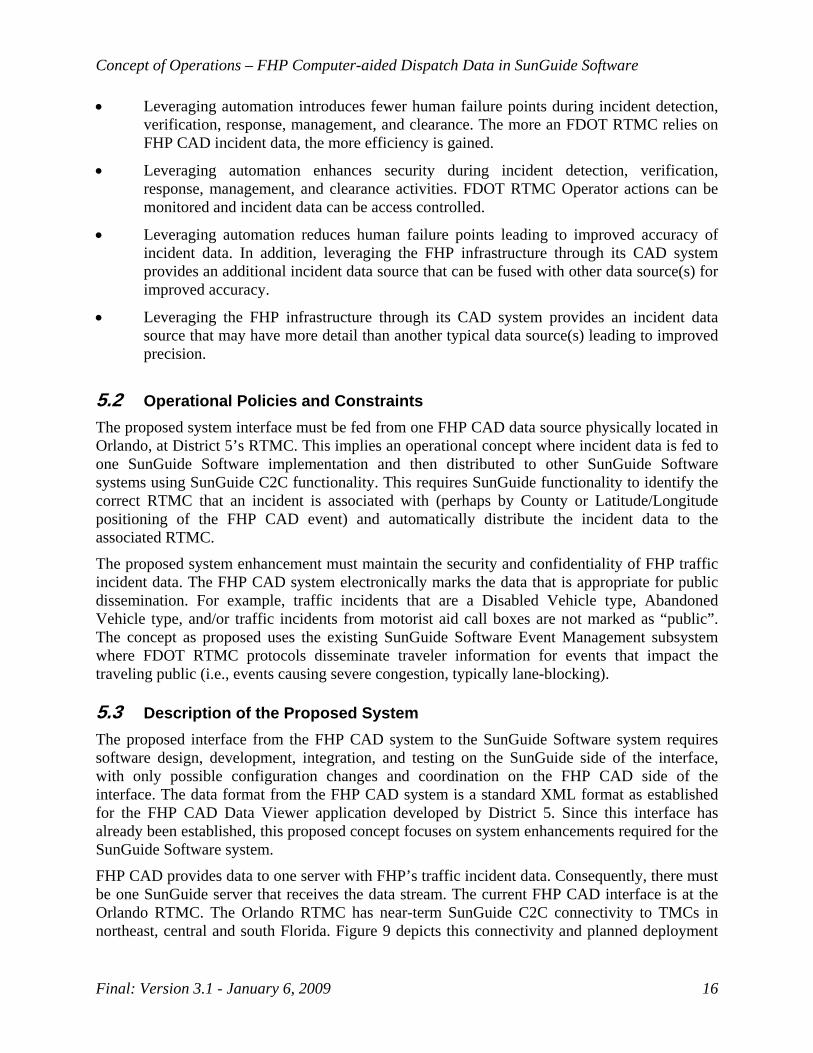
FHP CAD provides data to one server with FHP’s traffic incident data. Consequently, there must be one SunGuide server that receives the data stream. The current FHP CAD interface is at the Orlando RTMC. The Orlando RTMC has near-term SunGuide C2C connectivity to TMCs in northeast, central and south Florida. Figure 9 depicts this connectivity and planned deployment
Concept of Operations – FHP Computer-aided Dispatch Data in SunGuide Software
Final: Version 3.1 - January 6, 2009 17
of additional connectivity throughout the state. Note that the dotted lines are areal (wireless) communication links and the solid lines are hardwire links. In the near-term, the primary SunGuide FHP CAD data server is proposed to remain at the Orlando RTMC.
Leased MANs
F/O
ITS WAN Statewide
Deployment
District 1 RTMC Network
Ft. Myers
District 6 RTMC Network
Miami
Turnpike RTMC Network
Turkey Lake
F/ODistrict 7 RTMC Network
Tampa
District 2 RTMC Network
Jacksonville
ITS Test-Bed TERL NetworkTallahassee
District 3 RTMC Network
Pensacola
F/O
F/O
F/O
F/O
F/O
F/O
F/O
F/O
F/O
F/O
TurnpikeRTMC Network
Pompano
District 4 RTMC NetworkFt Lauderdale
F/O
F/O
F/O
District 5 RTMC Network
Orlando
ITS WAN connection Complete
ITS WAN connection Complete
ITS WAN connection Complete
ITS WAN connection Complete
ITS WAN connection 1st Qtr 2009
ITS WAN connection 1st Qtr 2009
ITS WAN connection 1st Qtr 2009
ITS WAN connection 4th Qtr 2009
ITS WAN connection 4th Qtr 2009
ITS WAN connection Date TBD District 3
RTMC NetworkTallahassee
ITS WAN connection Date TBD
ITS WAN Connection PhasingComplete - D4, D6, FTE Pompano, TERL1st Qtr 2009 - D2, D5, FTE Turkey Lake4th Qtr 2009 - D1, D7TBD - D3 Pensacola, D3 Tallahassee,
Note: Dates are dependent on funding, TMC completion and fiber implementation
Figure 9: ITS WAN Statewide Deployment
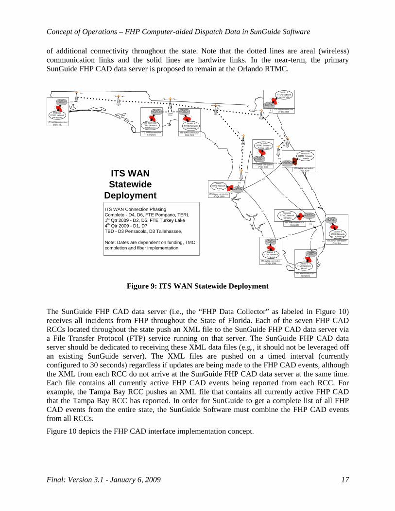
The SunGuide FHP CAD data server (i.e., the “FHP Data Collector” as labeled in Figure 10) receives all incidents from FHP throughout the State of Florida. Each of the seven FHP CAD RCCs located throughout the state push an XML file to the SunGuide FHP CAD data server via a File Transfer Protocol (FTP) service running on that server. The SunGuide FHP CAD data server should be dedicated to receiving these XML data files (e.g., it should not be leveraged off an existing SunGuide server). The XML files are pushed on a timed interval (currently configured to 30 seconds) regardless if updates are being made to the FHP CAD events, although the XML from each RCC do not arrive at the SunGuide FHP CAD data server at the same time. Each file contains all currently active FHP CAD events being reported from each RCC. For example, the Tampa Bay RCC pushes an XML file that contains all currently active FHP CAD that the Tampa Bay RCC has reported. In order for SunGuide to get a complete list of all FHP CAD events from the entire state, the SunGuide Software must combine the FHP CAD events from all RCCs.
Figure 10 depicts the FHP CAD interface implementation concept.
Concept of Operations – FHP Computer-aided Dispatch Data in SunGuide Software
Final: Version 3.1 - January 6, 2009 18
Figure 10: FHP CAD Interface Implementation Concept
In the process of consolidating data from FHP CAD, this data will have to be translated into fields used and recognized in SunGuide. This translation step may require reformatting of the data, including interpreting date formats and mapping textual descriptions to SunGuide event locations. Appendix A of this document lists the fields reported from FHP CAD. This appendix and the FHP CAD / FDOT integration document developed by CTS America (Data Elements for Supporting the Florida Department of Transportation CAD 511 Integration Project, Version 1.0, April 4, 2005) can be used as a basis for developing a translation mechanism. Appendix B of this document should also assist in interpreting and translating the FHP CAD data. The translation of the FHP CAD data is a critical step for maintaining data consistency throughout SunGuide.
The majority of the FHP CAD events are at locations not covered by FDOT RTMCs, such as local roads and parking lots. To avoid the manual filtering of these events by RTMC Operators, automated filtering is required in the SunGuide Software. FHP CAD events are provided with latitude/longitude coordinates and County information. The event location must be automatically analyzed in relation to the coordinates of FDOT RTMC-covered roadways as identified on the SunGuide Software Geographic Information System (GIS) base map to relate the event to the closest EM location. If an FHP CAD event is not associated by SunGuide to an FDOT RTMC-covered roadway, the incident data should be discarded.
If a roadway association is created, the event should be further filtered by associating the event by County which also associates the incident with an FDOT RTMC. The event should automatically be routed through the SunGuide Software C2C infrastructure, or some other mechanism, to the correct FDOT RTMC. During the design process, a decision will have to be made to perform filtering before, after, or before and after the event is routed to the correct FDOT RTMC.

Concept of Operations – FHP Computer-aided Dispatch Data in SunGuide Software
Final: Version 3.1 - January 6, 2009 19
After the event is received at the FDOT RTMC, the SunGuide IDS should generate an incident alert. The alert mechanism would provide a visual notification to the RTMC Operator through the SunGuide GUI. The incident alert approach allows the RTMC Operator to perform high-priority incident management activities, but still visually captures their attention. These alerts will use as much as possible the same alerting mechanism as used with other incident detection sources.
The IDS automatically checks if the FHP CAD event is an update of an existing FHP CAD event. It is then the RTMC operator’s responsibility to make decisions about how the FHP CAD event data is absorbed into the SunGuide Software system.
The FHP CAD event alert should be listed in the alert list on the right side of the Events List window. The following figure is an example of this alert list:
Figure 11: Highlighting the Alert List on the right side of the Events List window
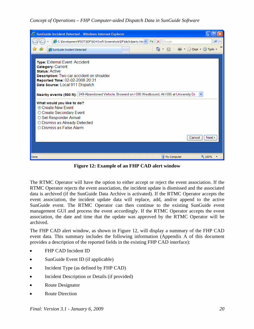
The alert should remain in the alert list until an operator determines what should be done with the FHP CAD event update using the FHP CAD alert window, consistent with other alerts currently managed by operation staff (i.e., VisioPaD and TSS alerts). Figure 12 is an example of what this FHP CAD alert window may look like (Note: the actual FHP CAD alert window will differ based on subsequent requirements). When an operator clicks the alert in the alert list, the notification window should be launched and the alert notification should be removed from the alert list to avoid multiple operators attempting to handle the same alert. After an FHP CAD event is considered handled, the alert should be removed from the alert list completely.
Alert List
Concept of Operations – FHP Computer-aided Dispatch Data in SunGuide Software
Final: Version 3.1 - January 6, 2009 20
Figure 12: Example of an FHP CAD alert window
The RTMC Operator will have the option to either accept or reject the event association. If the RTMC Operator rejects the event association, the incident update is dismissed and the associated data is archived (if the SunGuide Data Archive is activated). If the RTMC Operator accepts the event association, the incident update data will replace, add, and/or append to the active SunGuide event. The RTMC Operator can then continue to the existing SunGuide event management GUI and process the event accordingly. If the RTMC Operator accepts the event association, the date and time that the update was approved by the RTMC Operator will be archived.
The FHP CAD alert window, as shown in Figure 12, will display a summary of the FHP CAD event data. This summary includes the following information (Appendix A of this document provides a description of the reported fields in the existing FHP CAD interface):
• FHP CAD Incident ID
• SunGuide Event ID (if applicable)
• Incident Type (as defined by FHP CAD)
• Incident Description or Details (if provided)
• Route Designator
• Route Direction
Concept of Operations – FHP Computer-aided Dispatch Data in SunGuide Software
Final: Version 3.1 - January 6, 2009 21
• Linear Reference or Cross Street or Mile Marker (if provided)
• County
• Event Creation Date/Time
• Event Update Date/Time
• Trooper Dispatch Date/Time (if provided)
• Trooper Arrival Date/Time (if provided)
• RCC Originating the Event
Note that if the FHP CAD event has not yet been associated with a SunGuide event, the SunGuide Event ID would not appear in the FHP CAD alert window.
The FHP CAD alert window will provide the operator with the following options:
• Create New Event – Creates a new event with a new SunGuide event ID and automatically pre-fills in all applicable SunGuide event fields as retrieved from the FHP CAD event.
• Create Secondary Event – The operator will have the option to select the primary event. Creates a new event with a new SunGuide event ID and automatically pre-fills in all applicable SunGuide event fields as retrieved from the FHP CAD event.
• Associate Existing Event – The functionality of this option will differ depending on if the FHP CAD event has been previously associated with a SunGuide event.
o If the FHP CAD event has not been previously associated with a SunGuide event: The operator will be provided a list of active SunGuide events that the operator currently owns within a configurable geographic radius of the FHP CAD. If the closest active SunGuide event is not owned by the operator attempting to handle the FHP CAD alert, then the operator must take ownership of the SunGuide event before handling the FHP CAD alert. The selected SunGuide event will be associated with the FHP CAD event; when this occurs SunGuide will update the SunGuide event by automatically filling in the “FHP Incident #” field.
o If the FHP CAD event has been previously associated with a SunGuide event: The FHP CAD alert window will display the associated SunGuide event ID, though no updates to the SunGuide event will be made. This functionality is similar to the “Acknowledge, Take No Action” option. Highlighting modified fields may be considered as future functionality. This highlighting feature would work as follows: if the FHP CAD event has been associated with a SunGuide event, the FHP CAD-reported field values that are different than what currently exists in the associated SunGuide event should be highlighted.
• Set Responder Arrival – The functionality of this option will differ depending on if the FHP CAD event has been previously associated with a SunGuide event.
o If the FHP CAD event has not been previously associated with a SunGuide event: The operator will be provided a list of active SunGuide events that the operator currently owns within a configurable geographic radius of the FHP CAD. If the

Concept of Operations – FHP Computer-aided Dispatch Data in SunGuide Software
Final: Version 3.1 - January 6, 2009 22
closest active SunGuide event is not owned by the operator attempting to handle the FHP CAD alert, then the operator must take ownership of the SunGuide event before handling the FHP CAD alert. The selected SunGuide event will be associated and updated with the FHP CAD event; when this occurs SunGuide will update the SunGuide event by automatically filling in the “FHP Incident #” field and the FHP responder arrival time will be updated with the arrival time in the FHP CAD event.
o If the FHP CAD event has been previously associated with a SunGuide event: The FHP CAD alert window will display the associated SunGuide event ID. Upon selecting “Set Responder Arrival”, if the operator handling the alert owns the associated SunGuide event then the FHP responder arrival time will be updated with the arrival time from the FHP CAD event. Otherwise, the operator will be prompted by an alert that the event must be owned to make the responder arrival update.
• Acknowledge, Take No Action – The FHP CAD event alert will be removed from the alert list and the FHP CAD event archived as “Acknowledged” if the SunGuide Data Archive is activated. Note that after this is selected, updates to the acknowledged FHP CAD event will still continue to be reported in the FHP CAD alerts.
• Dismiss, As Already Detected – The FHP CAD event alert will be removed from the alert list and the FHP CAD event archived as “Already Detected” if the SunGuide Data Archive is activated. Note that after this is selected, updates to the dismissed FHP CAD event will not be reported in the FHP CAD alerts.
• Dismiss, As False Alarm – The FHP CAD event alert will be removed from the alert list and the FHP CAD event archived as a “False Alarm” if the SunGuide Data Archive is activated. Note that after this is selected, updates to the dismissed FHP CAD event will not be reported in the FHP CAD alerts.
After the operator selects one of the options listed above, the RTMC Operator can continue to update the existing SunGuide event management GUI and process the event accordingly. At this point, if the event was not dismissed the FHP CAD event will display on the operator map similar to other SunGuide events.
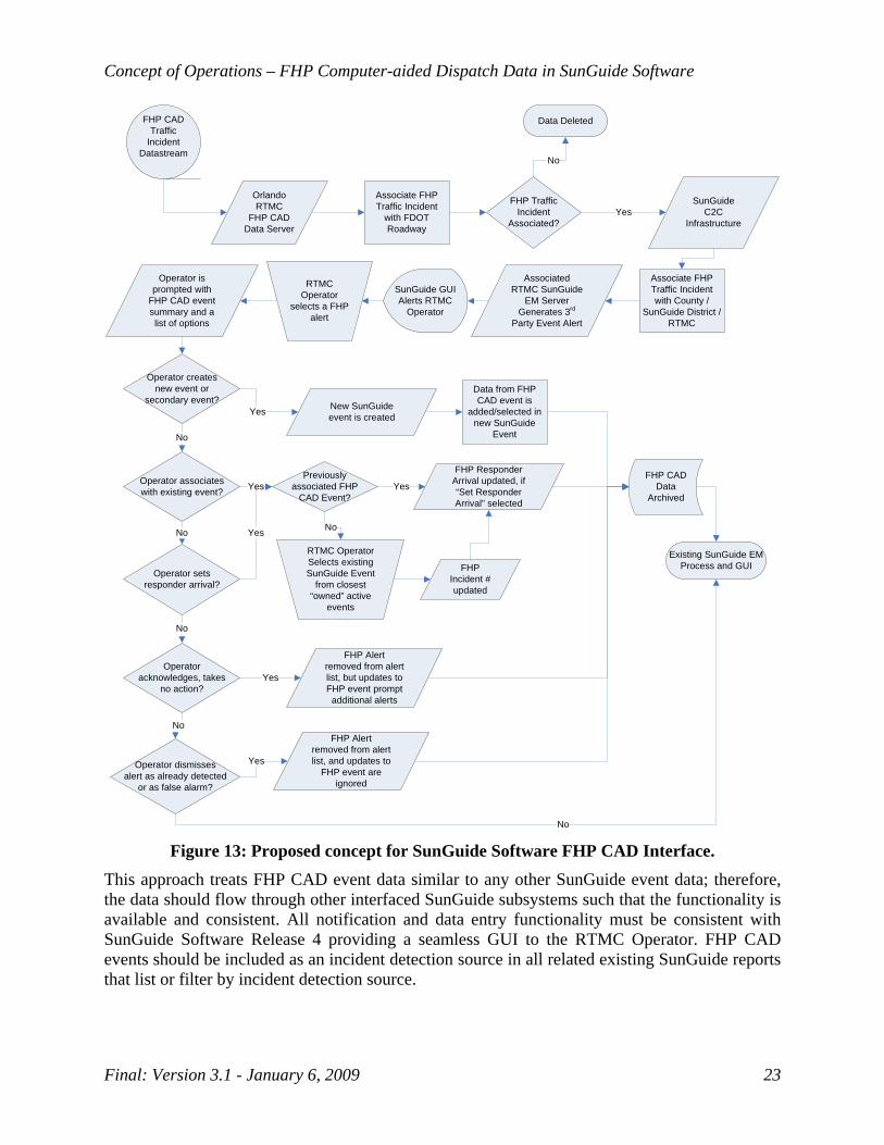
Following flow chart depicts the proposed FHP CAD interface concept in SunGuide Software:
Concept of Operations – FHP Computer-aided Dispatch Data in SunGuide Software
Final: Version 3.1 - January 6, 2009 23
Orlando RTMC
FHP CAD Data Server
FHP CAD Traffic
Incident Datastream
FHP Traffic Incident
Associated?
Data Deleted
No
Associate FHP Traffic Incident
with FDOT Roadway
Associate FHP Traffic Incident with County /
SunGuide District / RTMC
YesSunGuide
C2C Infrastructure
Associated RTMC SunGuide
EM Server Generates 3rd
Party Event Alert
Yes
Data from FHP CAD event is
added/selected in new SunGuide
Event
Previously associated FHP
CAD Event?
Existing SunGuide EM Process and GUI
SunGuide GUI Alerts RTMC
Operator
No
RTMC Operator Selects existing SunGuide Event
from closest “owned” active
events
YesFHP CAD
Data Archived
Operator createsnew event or
secondary event?
Operator associates with existing event?
Operator sets responder arrival?
Operator acknowledges, takes
no action?
Operator dismissesalert as already detected
or as false alarm?
Operator is prompted with
FHP CAD event summary and a list of options
No Yes
Yes
No
FHP Responder Arrival updated, if “Set Responder Arrival” selected
FHP Incident # updated
No
FHP Alert removed from alert list, but updates to FHP event prompt additional alerts
Yes
No
No
Yes
FHP Alert removed from alert list, and updates to
FHP event are ignored
RTMC Operator
selects a FHP alert
New SunGuide event is created
Figure 13: Proposed concept for SunGuide Software FHP CAD Interface.
This approach treats FHP CAD event data similar to any other SunGuide event data; therefore, the data should flow through other interfaced SunGuide subsystems such that the functionality is available and consistent. All notification and data entry functionality must be consistent with SunGuide Software Release 4 providing a seamless GUI to the RTMC Operator. FHP CAD events should be included as an incident detection source in all related existing SunGuide reports that list or filter by incident detection source.

Concept of Operations – FHP Computer-aided Dispatch Data in SunGuide Software
Final: Version 3.1 - January 6, 2009 24
RTMC Managers will be able to run a report to review the history of actions made by the RTMC Operator. This functionality must be consistent with the SunGuide Software Release 4 Reporting subsystem.
The availability and reliability of the proposed SunGuide system enhancement is dependent on the availability of the communications network from FHP as well as the communications Local Area Networks (LANs) and Wide Area Networks (WANs) internal to the FDOT. The proposed interface processing must not introduce latency that would significantly degrade the real-time status of the incident data. SunGuide must also provide a mechanism to monitor the interface with the FHP CAD system. This mechanism should be able to alert SunGuide operators and administrators of communication issues. These issues include alerting if one or more of the RCCs are not reporting updated FHP CAD data within a configurable amount of time. This monitoring and alerting mechanism should only alert the SunGuide deployment who is maintaining the interface with FHP CAD, which in the initial deployment will be District 5. Likewise, detailed logging of the interface with FHP CAD should only be housed at the deployment which is maintaining the interface, such as at the central server collecting the FHP CAD data.
The operational accuracy of the resulting SunGuide system enhancement is dependent on the quality of the data received from FHP.
The SunGuide Software interface enhancement is expandable to all FDOT RTMCs contributing to a high level of reusability. 5.4 Modes of Operation The proposed system interface has one mode of operation, although the operations at District 5 are more extensive than that of other SunGuide deployments. District 5’s deployment will include functionality to perform the initial collection and distribution of FHP CAD data. All deployments will include functionality to collect the consolidated FHP CAD data, possibly filter on what FHP CAD data is applicable to their District / jurisdiction, and provide the operator tools for incorporating the data into SunGuide events. The filtering of FHP CAD data may be performed at all deployments or at the deployment maintaining the FHP CAD interface; however, this will need to be determined during the design.
5.5 User Involvement and Interaction Following are the high-level, general user classes:
• FHP Dispatchers/Supervisors – are passive users (beneficiaries); typically will not interact directly with system.
• FDOT RTMC Operators – primary users; perform the manual activities as described in Section 5.3.
• FDOT RTMC Supervisors/Managers – secondary users; typically perform quality assurance (QA) and use data for performance measures reporting.
• FDOT SunGuide System Administrators – secondary users; responsible for monitoring and maintaining the interface with the FHP CAD system.
Concept of Operations – FHP Computer-aided Dispatch Data in SunGuide Software
Final: Version 3.1 - January 6, 2009 25
The added SunGuide functionality proposes to use the existing SunGuide permissions system. 5.6 Support Environment The FHP interface software and hardware is maintained by the FHP and its contractor(s).
The SunGuide Software is maintained and supported by FDOT Central Office (CO) and its SunGuide Software Support contractor. This support includes minor enhancements as required and approved by the FDOT CO and/or the Change Management Board (CMB). The required hardware and COTS software is maintained by the FDOT District (or its contractor) associated with each TMC.
The FDOT has an active CMB that provides oversight on changes to the SunGuide Software system. The proposed system enhancement falls under the existing change management process.
6. Operational Scenarios Refer to the FDOT District 4’s FHP CAD Data Integration in SunGuide for examples of an Operations storyline and a Management storyline. Note that these storylines were developed in advance of this document and do not completely and accurately portray the proposed Con Ops.
7. Summary of Impacts This section summarizes the operational impacts of the proposed system from the users’ perspective. The most significant impact on the FHP is the anticipated reduction in effort to communicate traffic incidents to the FDOT RTMCs.
The FDOT RTMCs are anticipated to receive a significant increase in incident detection data and real-time updates. This is particularly expected to impact the rural coverage areas and/or areas where ITS field infrastructure is not available. The added functionality gives the FDOT RTMCs the ability to provide the public with a higher level of service. While the automated nature of the incident data is expected to decrease the level of effort on the RTMC Operators, the concurrent increase in available data is expected to increase the level of incident management coverage and associated effort. The net increase or decrease in level of effort for the RTMC Operator will vary.
The increase in incident data is expected to result in a slight increase in the QA and reporting efforts on RTMC Supervisors and Managers. The FDOT Districts that implement this system enhancement must plan and prepare for these permanent impacts.
Training is required in advance of the system interface implementation. Operator and Administrator training and the associated training materials are available from the FDOT CO and its consultant/contractor. Each District should coordinate the required training with the FDOT CO prior to implementation. In addition, periodic follow-up training may be required as the system enhancement evolves in conjunction with the overall District RTMC and SunGuide training plans.
The most significant temporary impact will be during the deployment testing and independent verification and validation (IV&V) phases of the project. Initial deployment and IV&V on the FHP CAD to SunGuide Software interface is proposed at the Orlando RTMC. The deployment

Concept of Operations – FHP Computer-aided Dispatch Data in SunGuide Software
Final: Version 3.1 - January 6, 2009 26
and IV&V of the system enhancement using the C2C infrastructure is proposed at the Broward RTMC. Therefore, FDOT Districts 5 and 4, respectively, may experience temporary operational disruptions during the testing and IV&V phases.
During the deployment to the remainder of the TMCs, minor temporary impacts are anticipated that may include short-term operational disruptions.
8. Analysis of the Proposed System Following are the expected benefits of the proposed system enhancement:
• Reduction in incident notification time – this is quantitatively measured as a performance metric and is a key contributor to decreases in non-recurring congestion and secondary crashes.
• Reduction in incident verification time – FHP CAD traffic incident data can serve as input into incident verification, particularly where cameras and Road Rangers are not available; this is quantitatively measured as a performance metric and is a key contributor to decreases in non-recurring congestion and secondary crashes.
• Reduction in incident response time – additional incident details provided by leveraging the FHP infrastructure assists the RTMC Operator in dispatching appropriate resources and disseminating appropriate traveler information; this is quantitatively measured as a performance metric and is a key contributor to decreases in non-recurring congestion and secondary crashes.
• Reduction in incident management and clearance time – additional incident details provided by leveraging the FHP infrastructure assists the RTMC Operator in the real-time management of the incident and allows real-time adjustments in resources and traveler information; this is quantitatively measured as a performance metric and is a key contributor to decreases in non-recurring congestion and secondary crashes.
• Reduction in workload on FHP Dispatchers – this likely is a qualitative assessment.
• Reduction in workload and/or increased level of service by FDOT RTMC Operators – this likely is a qualitative assessment and the magnitude of the benefit varies from TMC to TMC.
• Improved consistency in the FDOT RTMC level of service for incident management – this likely is a qualitative assessment and the magnitude of the benefit varies from TMC to TMC; improvements in level of service consistency are most likely to be seen in RTMCs that do not have enough RTMC operations staffing on all shifts and/or the staffing levels vary greatly from shift to shift; improvements may also be seen in emergency recovery operations where all ITS infrastructure is not back on-line.
• Improved security for FHP CAD traffic incident data used by the FDOT – this likely is a qualitative assessment; increased automation of FHP incident data transfer along with the ability to electronically monitor RTMC Operator actions provides fewer security failure points.
Concept of Operations – FHP Computer-aided Dispatch Data in SunGuide Software
Final: Version 3.1 - January 6, 2009 27
• Improved accuracy and precision of FDOT incident data – this likely is a qualitative and quantitative assessment; the significant increase and automation of FHP incident data provides a wider range of data with fewer mistakes caused by verbal transfer and manual entry.
9. Notes There are no notes at this time.

Appendix A FHP CAD XML Description
Appendix A: FHP CAD XML Description
Final: Version 3.1 - January 6, 2009 A-1
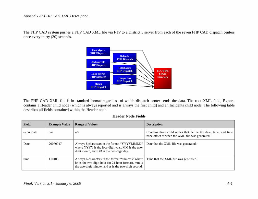
The FHP CAD system pushes a FHP CAD XML file via FTP to a District 5 server from each of the seven FHP CAD dispatch centers once every thirty (30) seconds.
Fort Myers
FHP Dispatch
Jacksonville FHP Dispatch
Lake WorthFHP Dispatch
Orlando FHP Dispatch
TallahasseeFHP Dispatch FDOT D 5
Server Directory
Miami FHP Dispatch
Tampa BayFHP Dispatch
The FHP CAD XML file is in standard format regardless of which dispatch center sends the data. The root XML field, Export, contains a Header child node (which is always reported and is always the first child) and an Incidents child node. The following table describes all fields contained within the Header node.
Header Node Fields
Field Example Value Range of Values Description
exportdate n/a n/a Contains three child nodes that define the date, time, and time zone offset of when the XML file was generated.
Date 20070917 Always 8 characters in the format “YYYYMMDD” where YYYY is the four-digit year, MM is the two-digit month, and DD is the two-digit day.
Date that the XML file was generated.
time 110105 Always 6 characters in the format “hhmmss” where hh is the two-digit hour (in 24-hour format), mm is the two-digit minute, and ss is the two-digit second.
Time that the XML file was generated.
Appendix A: FHP CAD XML Description
Final: Version 3.1 - January 6, 2009 A-2
Field Example Value Range of Values Description
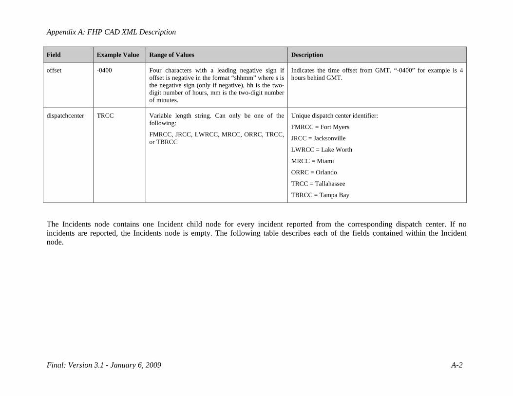
offset -0400 Four characters with a leading negative sign if offset is negative in the format “shhmm” where s is the negative sign (only if negative), hh is the two-digit number of hours, mm is the two-digit number of minutes.
Indicates the time offset from GMT. “-0400” for example is 4 hours behind GMT.
dispatchcenter TRCC Variable length string. Can only be one of the following:
FMRCC, JRCC, LWRCC, MRCC, ORRC, TRCC, or TBRCC
Unique dispatch center identifier:
FMRCC = Fort Myers
JRCC = Jacksonville
LWRCC = Lake Worth
MRCC = Miami
ORRC = Orlando
TRCC = Tallahassee
TBRCC = Tampa Bay
The Incidents node contains one Incident child node for every incident reported from the corresponding dispatch center. If no incidents are reported, the Incidents node is empty. The following table describes each of the fields contained within the Incident node.

Appendix A: FHP CAD XML Description
Final: Version 3.1 - January 6, 2009 A-3
Incident Node Fields
Field Example Value Range of Values Description
senderIncidentID TRCC07CAD068160 Alpha-numeric, 15-character A unique identifier for the incident. Identifier does not change regardless of how many updates are made to the incident.
author SST617-CAD Alpha-numeric and dash “-” characters, variable length
Identifies the FHP CAD operator who generated/updated the incident.
urgency 10 Integer values from 1 to 10 Indicates the urgency of the incident, 1 is the highest and 10 is the lowest.
updateTime n/a n/a Contains three child nodes that define the date, time, and time zone offset of when the incident report was last updated.
date 20070917 Always 8 characters in the format “YYYYMMDD” where YYYY is the four-digit year, MM is the two-digit month, and DD is the two-digit day.
Date that the incident report was last updated.
time 110105 Always 6 characters in the format “hhmmss” where hh is the two-digit hour (in 24-hour format), mm is the two-digit minute, and ss is the two-digit second.
Time that the incident report was last updated.
offset -0400 Four characters with a leading negative sign if offset is negative in the format “shhmm” where s is the negative sign (only if negative), hh is the two-digit number of hours, mm is the two-digit number of minutes.
Indicates the time offset from GMT. “-0400” for example is 4 hours behind GMT.
createdTime n/a n/a Contains three child nodes that define the date, time, and time zone offset of when the incident report was originally generated.
Appendix A: FHP CAD XML Description
Final: Version 3.1 - January 6, 2009 A-4
Field Example Value Range of Values Description
date 20070917 Always 8 characters in the format “YYYYMMDD” where YYYY is the four-digit year, MM is the two-digit month, and DD is the two-digit day.
Date that the incident report was originally generated.
time 110105 Always 6 characters in the format “hhmmss” where hh is the two-digit hour (in 24-hour format), mm is the two-digit minute, and ss is the two-digit second.
Time that the incident report was originally generated.
offset -0400 Four characters with a leading negative sign if offset is negative in the format “shhmm” where s is the negative sign (only if negative), hh is the two-digit number of hours, mm is the two-digit number of minutes.
Indicates the time offset from GMT. “-0400” for example is 4 hours behind GMT.
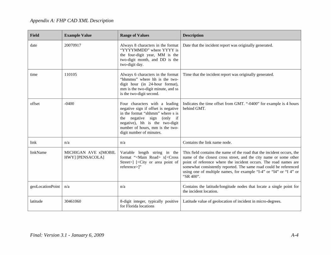
link n/a n/a Contains the link name node.
linkName MICHIGAN AVE x[MOBIL HWY] [PENSACOLA]
Variable length string in the format “<Main Road> x[<Cross Street>] [<City or area point of reference>]”
This field contains the name of the road that the incident occurs, the name of the closest cross street, and the city name or some other point of reference where the incident occurs. The road names are somewhat consistently reported. The same road could be referenced using one of multiple names, for example “I-4” or “I4” or “I 4” or “SR 400”.
geoLocationPoint n/a n/a Contains the latitude/longitude nodes that locate a single point for the incident location.
latitude 30461060 8-digit integer, typically positive for Florida locations
Latitude value of geolocation of incident in micro-degrees.
Appendix A: FHP CAD XML Description
Final: Version 3.1 - January 6, 2009 A-5
Field Example Value Range of Values Description
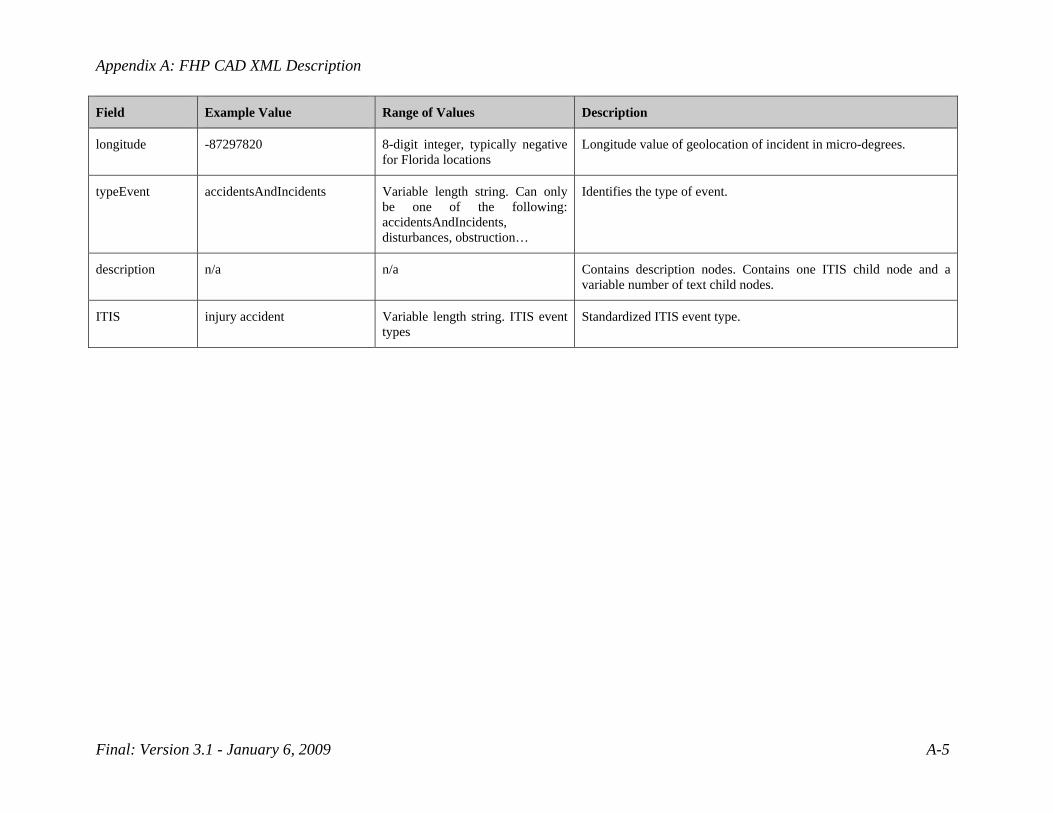
longitude -87297820 8-digit integer, typically negative for Florida locations
Longitude value of geolocation of incident in micro-degrees.
typeEvent accidentsAndIncidents Variable length string. Can only be one of the following: accidentsAndIncidents, disturbances, obstruction…
Identifies the type of event.
description n/a n/a Contains description nodes. Contains one ITIS child node and a variable number of text child nodes.
ITIS injury accident Variable length string. ITIS event types
Standardized ITIS event type.
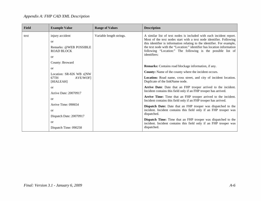
Appendix A: FHP CAD XML Description
Final: Version 3.1 - January 6, 2009 A-6
Field Example Value Range of Values Description
text injury accident
or
Remarks: @WEB POSSIBLE ROAD BLOCK
or
County: Broward
or
Location: SR-826 WB x[NW 67TH AVE/WOF] [HIALEAH]
or
Arrive Date: 20070917
or
Arrive Time: 090654
or
Dispatch Date: 20070917
or
Dispatch Time: 090258
Variable length strings. A similar list of text nodes is included with each incident report. Most of the text nodes start with a text node identifier. Following this identifier is information relating to the identifier. For example, the text node with the “Location:” identifier has location information following “Location:” The following is the possible list of identifiers:
Remarks: Contains road blockage information, if any.
County: Name of the county where the incident occurs.
Location: Road name, cross street, and city of incident location. Duplicate of the linkName node.
Arrive Date: Date that an FHP trooper arrived to the incident. Incident contains this field only if an FHP trooper has arrived.
Arrive Time: Time that an FHP trooper arrived to the incident. Incident contains this field only if an FHP trooper has arrived.
Dispatch Date: Date that an FHP trooper was dispatched to the incident. Incident contains this field only if an FHP trooper was dispatched.
Dispatch Time: Time that an FHP trooper was dispatched to the incident. Incident contains this field only if an FHP trooper was dispatched.

Appendix B Parsing the FHP CAD Link Element

Appendix B: Parsing the FHP CAD Link Element
Final: Version 3.1 - January 6, 2009 B-1
According to the FHP CAD Interface Con Ops document, the “linkName” element should be formatted as shown below:
<Main Road> x[<Cross Street>] [<City or area point of reference>]
The following list defines the current “linkName” parsing steps used by the FHP CAD Interface software:
1. Split the string into halves at the “x[“. Note that an incident without the “x[“ in the link data will generate a FHP incident alert in SunGuide without a linear reference, roadway, or direction, although latitude and longitude will be provided if present.
2. Parse the first half of the link (e.g., <Main Road>):
a. Search for text in brackets []. Everything inside the brackets is used to determine the linear reference and removed from the string. Note that this set of brackets before the “x[“ and its content is not defined in the documentation provided to SwRI; the parsing described is based solely on observations of retrieved FHP CAD data.
i. 8TH ST [EAST OF] x[…. => 8TH ST x[…. ii. Linear Reference = EAST OF
b. The remaining text in the string is split into single strings using white space as a delimiter.
c. Search for directional elements (NB, SB, WB, or EB). If found, set as the direction element and remove it from the list of strings. This step is also based on observations rather than documentation.
i. I-95 NB JSOF x[…. => I-95 JSOF x[…. (separate) ii. I-95NB JSOF x[…. => I-95 JSOF x[…. (joined to the roadway)
iii. Direction = North d. Search for the linear reference key words (JSOF, JNOF, JEOF, JWOF, SOF, NOF, WOF,
EOF, JSO, JNO, JEO, JWO, or XR). If found, the keyword and everything located after it in the string is set as the linear reference. This step is also based on observations rather than documentation.
i. 9 NOF 842 x[….. => 9 x[….. ii. Linear Reference = NOF 842
e. Everything else is set as the roadway. i. If the roadway is a single number by itself, “SR” will be added to the
beginning. 1. Roadway = 9 would become Roadway = SR9
Note: We have not seen a case where there were brackets to the left of “x[” and a linear reference keyword. If this were to happen, the linear reference outside the brackets would take precedence.
3. Parse the second half of the link (e.g., [<Cross Street>] [<City or area point of reference>]):
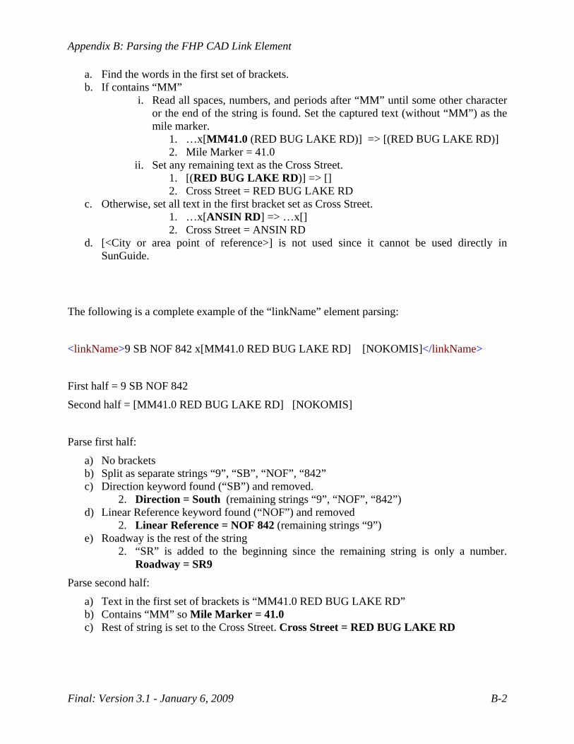
Appendix B: Parsing the FHP CAD Link Element
Final: Version 3.1 - January 6, 2009 B-2
a. Find the words in the first set of brackets. b. If contains “MM”
i. Read all spaces, numbers, and periods after “MM” until some other character or the end of the string is found. Set the captured text (without “MM”) as the mile marker.
1. …x[MM41.0 (RED BUG LAKE RD)] => [(RED BUG LAKE RD)] 2. Mile Marker = 41.0
ii. Set any remaining text as the Cross Street. 1. [(RED BUG LAKE RD)] => [] 2. Cross Street = RED BUG LAKE RD
c. Otherwise, set all text in the first bracket set as Cross Street. 1. …x[ANSIN RD] => …x[] 2. Cross Street = ANSIN RD
d. [<City or area point of reference>] is not used since it cannot be used directly in SunGuide.
The following is a complete example of the “linkName” element parsing:
<linkName>9 SB NOF 842 x[MM41.0 RED BUG LAKE RD] [NOKOMIS]</linkName>
First half = 9 SB NOF 842
Second half = [MM41.0 RED BUG LAKE RD] [NOKOMIS]
Parse first half:
a) No brackets b) Split as separate strings “9”, “SB”, “NOF”, “842” c) Direction keyword found (“SB”) and removed.
2. Direction = South (remaining strings “9”, “NOF”, “842”) d) Linear Reference keyword found (“NOF”) and removed
2. Linear Reference = NOF 842 (remaining strings “9”) e) Roadway is the rest of the string
2. “SR” is added to the beginning since the remaining string is only a number. Roadway = SR9
Parse second half:
a) Text in the first set of brackets is “MM41.0 RED BUG LAKE RD” b) Contains “MM” so Mile Marker = 41.0 c) Rest of string is set to the Cross Street. Cross Street = RED BUG LAKE RD
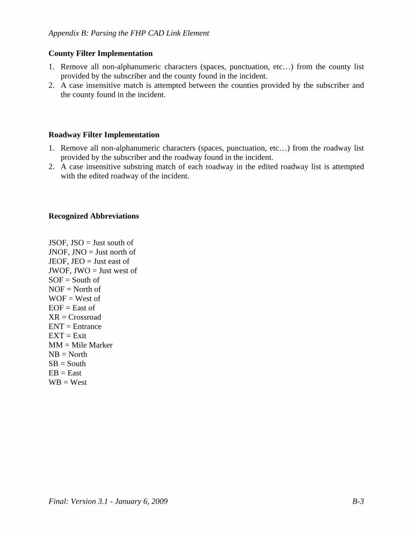
Appendix B: Parsing the FHP CAD Link Element
Final: Version 3.1 - January 6, 2009 B-3
County Filter Implementation 1. Remove all non-alphanumeric characters (spaces, punctuation, etc…) from the county list
provided by the subscriber and the county found in the incident. 2. A case insensitive match is attempted between the counties provided by the subscriber and
the county found in the incident.
Roadway Filter Implementation 1. Remove all non-alphanumeric characters (spaces, punctuation, etc…) from the roadway list
provided by the subscriber and the roadway found in the incident. 2. A case insensitive substring match of each roadway in the edited roadway list is attempted
with the edited roadway of the incident.
Recognized Abbreviations
JSOF, JSO = Just south of JNOF, JNO = Just north of JEOF, JEO = Just east of JWOF, JWO = Just west of SOF = South of NOF = North of WOF = West of EOF = East of XR = Crossroad ENT = Entrance EXT = Exit MM = Mile Marker NB = North SB = South EB = East WB = West