Concept HDL Libraries Reference - Istituto Nazionale di ...statistics.roma2.infn.it/~sabene/CADENCE...
222
Concept HDL Libraries Reference Product Version 14.2 January 2002 1997-2002 Cadence Design Systems, Inc. All rights reserved. Printed in the United States of America. Cadence Design Systems, Inc., 555 River Oaks Parkway, San Jose, CA 95134, USA Trademarks: Trademarks and service marks of Cadence Design Systems, Inc. (Cadence) contained in this document are attributed to Cadence with the appropriate symbol. For queries regarding Cadence’s trademarks, contact the corporate legal department at the address shown above or call 1-800-862-4522. All other trademarks are the property of their respective holders. Restricted Print Permission: This publication is protected by copyright and any unauthorized use of this publication may violate copyright, trademark, and other laws. Except as specified in this permission statement, this publication may not be copied, reproduced, modified, published, uploaded, posted, transmitted, or distributed in any way, without prior written permission from Cadence. This statement grants you permission to print one (1) hard copy of this publication subject to the following conditions: 1. The publication may be used solely for personal, informational, and noncommercial purposes; 2. The publication may not be modified in any way; 3. Any copy of the publication or portion thereof must include all original copyright, trademark, and other proprietary notices and this permission statement; and 4. Cadence reserves the right to revoke this authorization at any time, and any such use shall be discontinued immediately upon written notice from Cadence. Disclaimer: Information in this publication is subject to change without notice and does not represent a commitment on the part of Cadence. The information contained herein is the proprietary and confidential information of Cadence or its licensors, and is supplied subject to, and may be used only by Cadence’s customer in accordance with, a written agreement between Cadence and its customer. Except as may be explicitly set forth in such agreement, Cadence does not make, and expressly disclaims, any representations or warranties as to the completeness, accuracy or usefulness of the information contained in this document. Cadence does not warrant that use of such information will not infringe any third party rights, nor does Cadence assume any liability for damages or costs of any kind that may result from use of such information. Restricted Rights: Use, duplication, or disclosure by the Government is subject to restrictions as set forth in FAR52.227-14 and DFAR252.227-7013 et seq. or its successor.
Transcript of Concept HDL Libraries Reference - Istituto Nazionale di ...statistics.roma2.infn.it/~sabene/CADENCE...

Concept HDL Libraries Reference
Product Version 14.2January 2002
1997-2002 Cadence Design Systems, Inc. All rights reserved.Printed in the United States of America.
Cadence Design Systems, Inc., 555 River Oaks Parkway, San Jose, CA 95134, USA
Trademarks: Trademarks and service marks of Cadence Design Systems, Inc. (Cadence) contained in thisdocument are attributed to Cadence with the appropriate symbol. For queries regarding Cadence’s trademarks,contact the corporate legal department at the address shown above or call 1-800-862-4522.
All other trademarks are the property of their respective holders.
Restricted Print Permission: This publication is protected by copyright and any unauthorized use of thispublication may violate copyright, trademark, and other laws. Except as specified in this permission statement,this publication may not be copied, reproduced, modified, published, uploaded, posted, transmitted, ordistributed in any way, without prior written permission from Cadence. This statement grants you permission toprint one (1) hard copy of this publication subject to the following conditions:
1. The publication may be used solely for personal, informational, and noncommercial purposes;2. The publication may not be modified in any way;3. Any copy of the publication or portion thereof must include all original copyright, trademark, and other
proprietary notices and this permission statement; and4. Cadence reserves the right to revoke this authorization at any time, and any such use shall be
discontinued immediately upon written notice from Cadence.
Disclaimer: Information in this publication is subject to change without notice and does not represent acommitment on the part of Cadence. The information contained herein is the proprietary and confidentialinformation of Cadence or its licensors, and is supplied subject to, and may be used only by Cadence’s customerin accordance with, a written agreement between Cadence and its customer. Except as may be explicitly setforth in such agreement, Cadence does not make, and expressly disclaims, any representations or warrantiesas to the completeness, accuracy or usefulness of the information contained in this document. Cadence doesnot warrant that use of such information will not infringe any third party rights, nor does Cadence assume anyliability for damages or costs of any kind that may result from use of such information.
Restricted Rights: Use, duplication, or disclosure by the Government is subject to restrictions as set forth inFAR52.227-14 and DFAR252.227-7013 et seq. or its successor.

Concept HDL Libraries Reference
Contents
Preface . . . . . . . . . . . . . . . . . . . . . . . . . . . . . . . . . . . . . . . . . . . . . . . . . . . . . . . . . . . . . 17
About This Guide . . . . . . . . . . . . . . . . . . . . . . . . . . . . . . . . . . . . . . . . . . . . . . . . . . . . . . . 17 Brief Outline of All the Chapters . . . . . . . . . . . . . . . . . . . . . . . . . . . . . . . . . . . . . . . . . . . 17Typographical conventions . . . . . . . . . . . . . . . . . . . . . . . . . . . . . . . . . . . . . . . . . . . . . . . . 18
1Library Fundamentals . . . . . . . . . . . . . . . . . . . . . . . . . . . . . . . . . . . . . . . . . . . . 21
What is a library? . . . . . . . . . . . . . . . . . . . . . . . . . . . . . . . . . . . . . . . . . . . . . . . . . . . . . . . 21How is a library stored on the disk? . . . . . . . . . . . . . . . . . . . . . . . . . . . . . . . . . . . . . . . . . 21Lib-Cell-View Architecture . . . . . . . . . . . . . . . . . . . . . . . . . . . . . . . . . . . . . . . . . . . . . . . . 22
Symbol (sym) View . . . . . . . . . . . . . . . . . . . . . . . . . . . . . . . . . . . . . . . . . . . . . . . . . . . 23Package (chips) View . . . . . . . . . . . . . . . . . . . . . . . . . . . . . . . . . . . . . . . . . . . . . . . . . 25Entity View . . . . . . . . . . . . . . . . . . . . . . . . . . . . . . . . . . . . . . . . . . . . . . . . . . . . . . . . . 26Simulation View . . . . . . . . . . . . . . . . . . . . . . . . . . . . . . . . . . . . . . . . . . . . . . . . . . . . . 26Part Table View . . . . . . . . . . . . . . . . . . . . . . . . . . . . . . . . . . . . . . . . . . . . . . . . . . . . . . 26Map Views . . . . . . . . . . . . . . . . . . . . . . . . . . . . . . . . . . . . . . . . . . . . . . . . . . . . . . . . . 26
The Master.tag File . . . . . . . . . . . . . . . . . . . . . . . . . . . . . . . . . . . . . . . . . . . . . . . . . . . . . 28The cds.lib File . . . . . . . . . . . . . . . . . . . . . . . . . . . . . . . . . . . . . . . . . . . . . . . . . . . . . . . . . 28
cds.lib Syntax Rules . . . . . . . . . . . . . . . . . . . . . . . . . . . . . . . . . . . . . . . . . . . . . . . . . . 30Binding One Library to Multiple Directories . . . . . . . . . . . . . . . . . . . . . . . . . . . . . . . . 31
Library Level Files . . . . . . . . . . . . . . . . . . . . . . . . . . . . . . . . . . . . . . . . . . . . . . . . . . . . . . 32Category Files (.cat files) . . . . . . . . . . . . . . . . . . . . . . . . . . . . . . . . . . . . . . . . . . . . . . 32Physical Part Table File (.ptf file) . . . . . . . . . . . . . . . . . . . . . . . . . . . . . . . . . . . . . . . . 32
January 2002 3 Product Version 14.2

Concept HDL Libraries Reference
2Development Decisions and Processes . . . . . . . . . . . . . . . . . . . . . . . 33
Library Development Decisions . . . . . . . . . . . . . . . . . . . . . . . . . . . . . . . . . . . . . . . . . . . . 33Library Development Process . . . . . . . . . . . . . . . . . . . . . . . . . . . . . . . . . . . . . . . . . . . . . 33
3Cadence Digital Library Standards . . . . . . . . . . . . . . . . . . . . . . . . . . . . . 35
Overview . . . . . . . . . . . . . . . . . . . . . . . . . . . . . . . . . . . . . . . . . . . . . . . . . . . . . . . . . . . . . 35Schematic Part Symbols . . . . . . . . . . . . . . . . . . . . . . . . . . . . . . . . . . . . . . . . . . . . . . . . . 35
Symbol Size . . . . . . . . . . . . . . . . . . . . . . . . . . . . . . . . . . . . . . . . . . . . . . . . . . . . . . . . 36Symbol Versions . . . . . . . . . . . . . . . . . . . . . . . . . . . . . . . . . . . . . . . . . . . . . . . . . . . . . 36Pin Stubs . . . . . . . . . . . . . . . . . . . . . . . . . . . . . . . . . . . . . . . . . . . . . . . . . . . . . . . . . . 37Pin to Pin Spacing . . . . . . . . . . . . . . . . . . . . . . . . . . . . . . . . . . . . . . . . . . . . . . . . . . . 38Pin Bubbles . . . . . . . . . . . . . . . . . . . . . . . . . . . . . . . . . . . . . . . . . . . . . . . . . . . . . . . . 38Pin Types . . . . . . . . . . . . . . . . . . . . . . . . . . . . . . . . . . . . . . . . . . . . . . . . . . . . . . . . . . 38Pin Naming . . . . . . . . . . . . . . . . . . . . . . . . . . . . . . . . . . . . . . . . . . . . . . . . . . . . . . . . . 39Pin Notes . . . . . . . . . . . . . . . . . . . . . . . . . . . . . . . . . . . . . . . . . . . . . . . . . . . . . . . . . . 40Symbol Notes . . . . . . . . . . . . . . . . . . . . . . . . . . . . . . . . . . . . . . . . . . . . . . . . . . . . . . . 41Properties . . . . . . . . . . . . . . . . . . . . . . . . . . . . . . . . . . . . . . . . . . . . . . . . . . . . . . . . . . 41Symbol Naming . . . . . . . . . . . . . . . . . . . . . . . . . . . . . . . . . . . . . . . . . . . . . . . . . . . . . 42Bussed Pins . . . . . . . . . . . . . . . . . . . . . . . . . . . . . . . . . . . . . . . . . . . . . . . . . . . . . . . . 42
The Chips.prt File . . . . . . . . . . . . . . . . . . . . . . . . . . . . . . . . . . . . . . . . . . . . . . . . . . . . . . 43Comments in the chips.prt File . . . . . . . . . . . . . . . . . . . . . . . . . . . . . . . . . . . . . . 45Signal Property in Chips View . . . . . . . . . . . . . . . . . . . . . . . . . . . . . . . . . . . . . . . . . . 45
Part Table file . . . . . . . . . . . . . . . . . . . . . . . . . . . . . . . . . . . . . . . . . . . . . . . . . . . . . . . . . . 46Physical Part Table File Format . . . . . . . . . . . . . . . . . . . . . . . . . . . . . . . . . . . . . . . . . . . . 48
Syntax . . . . . . . . . . . . . . . . . . . . . . . . . . . . . . . . . . . . . . . . . . . . . . . . . . . . . . . . . . . . 48PART ‘part_name’ . . . . . . . . . . . . . . . . . . . . . . . . . . . . . . . . . . . . . . . . . . . . . . . . . . . 50Part_Type Property_List . . . . . . . . . . . . . . . . . . . . . . . . . . . . . . . . . . . . . . . . . . . . . . . 50table_format_definition . . . . . . . . . . . . . . . . . . . . . . . . . . . . . . . . . . . . . . . . . . . . . . . . 51Part Table Entries . . . . . . . . . . . . . . . . . . . . . . . . . . . . . . . . . . . . . . . . . . . . . . . . . . . . 53Adding Mechanical Parts to the chips.prt File . . . . . . . . . . . . . . . . . . . . . . . . . . . . . . 55Part Subtype Names . . . . . . . . . . . . . . . . . . . . . . . . . . . . . . . . . . . . . . . . . . . . . . . . . 55Sample Physical Part Table . . . . . . . . . . . . . . . . . . . . . . . . . . . . . . . . . . . . . . . . . . . . 59
January 2002 4 Product Version 14.2
Concept HDL Libraries Reference
Standards for Symbols . . . . . . . . . . . . . . . . . . . . . . . . . . . . . . . . . . . . . . . . . . . . . . . . . . . 62Standards for Physical Information . . . . . . . . . . . . . . . . . . . . . . . . . . . . . . . . . . . . . . . 64
4Simulation Views. . . . . . . . . . . . . . . . . . . . . . . . . . . . . . . . . . . . . . . . . . . . . . . . . . 67
Overview . . . . . . . . . . . . . . . . . . . . . . . . . . . . . . . . . . . . . . . . . . . . . . . . . . . . . . . . . . . . . 67Verilog Map File . . . . . . . . . . . . . . . . . . . . . . . . . . . . . . . . . . . . . . . . . . . . . . . . . . . . . . . . 67
PRIMITIVE Section . . . . . . . . . . . . . . . . . . . . . . . . . . . . . . . . . . . . . . . . . . . . . . . . . . 68PIN MAP Section . . . . . . . . . . . . . . . . . . . . . . . . . . . . . . . . . . . . . . . . . . . . . . . . . . . . 71
Examples of Verilog Map Files . . . . . . . . . . . . . . . . . . . . . . . . . . . . . . . . . . . . . . . . . . . . 74Verilog Model Without Sections . . . . . . . . . . . . . . . . . . . . . . . . . . . . . . . . . . . . . . . . . 74Verilog Model with Sections . . . . . . . . . . . . . . . . . . . . . . . . . . . . . . . . . . . . . . . . . . . . 75SWIFT Model with Sections . . . . . . . . . . . . . . . . . . . . . . . . . . . . . . . . . . . . . . . . . . . . 76Verilog Model for Asymmetrical Parts . . . . . . . . . . . . . . . . . . . . . . . . . . . . . . . . . . . . . 77
Verilog Wrappers . . . . . . . . . . . . . . . . . . . . . . . . . . . . . . . . . . . . . . . . . . . . . . . . . . . . . . . 77Examples of Verilog Wrappers . . . . . . . . . . . . . . . . . . . . . . . . . . . . . . . . . . . . . . . . . . . . . 78
Verilog Wrapper Without Sections . . . . . . . . . . . . . . . . . . . . . . . . . . . . . . . . . . . . . . . 78Verilog Wrapper for Part With Sections . . . . . . . . . . . . . . . . . . . . . . . . . . . . . . . . . . . 79Verilog Wrapper for an Asymmetrical Part . . . . . . . . . . . . . . . . . . . . . . . . . . . . . . . . . 80
VHDL Map File . . . . . . . . . . . . . . . . . . . . . . . . . . . . . . . . . . . . . . . . . . . . . . . . . . . . . . . . 81VHDL Map File Format . . . . . . . . . . . . . . . . . . . . . . . . . . . . . . . . . . . . . . . . . . . . . . . . 81PRIMITIVE Section . . . . . . . . . . . . . . . . . . . . . . . . . . . . . . . . . . . . . . . . . . . . . . . . . . 82PIN MAP Section . . . . . . . . . . . . . . . . . . . . . . . . . . . . . . . . . . . . . . . . . . . . . . . . . . . . 84
Examples of VHDL Map Files . . . . . . . . . . . . . . . . . . . . . . . . . . . . . . . . . . . . . . . . . . . . . 86VHDL Model Without Sections . . . . . . . . . . . . . . . . . . . . . . . . . . . . . . . . . . . . . . . . . . 87VHDL Model with Sections . . . . . . . . . . . . . . . . . . . . . . . . . . . . . . . . . . . . . . . . . . . . . 88VHDL Model for Asymmetrical Parts . . . . . . . . . . . . . . . . . . . . . . . . . . . . . . . . . . . . . 88
VHDL Wrappers . . . . . . . . . . . . . . . . . . . . . . . . . . . . . . . . . . . . . . . . . . . . . . . . . . . . . . . . 89Mapping Scenarios . . . . . . . . . . . . . . . . . . . . . . . . . . . . . . . . . . . . . . . . . . . . . . . . . . . . . 90
Mapping Scalar Pins With Scalar Ports . . . . . . . . . . . . . . . . . . . . . . . . . . . . . . . . . . . 90Mapping Vector Symbol Pins With Scalar Model Ports . . . . . . . . . . . . . . . . . . . . . . . 91Mapping Scalar Pins With Vector Ports . . . . . . . . . . . . . . . . . . . . . . . . . . . . . . . . . . . 92Mapping Vector Pins With Vector Ports of Equal Size . . . . . . . . . . . . . . . . . . . . . . . . 93Mapping Vector Pins With a Combination of Vector Ports: . . . . . . . . . . . . . . . . . . . . . 94Handling Sizeable Parts . . . . . . . . . . . . . . . . . . . . . . . . . . . . . . . . . . . . . . . . . . . . . . . 96
January 2002 5 Product Version 14.2

Concept HDL Libraries Reference
Case Sensitivity . . . . . . . . . . . . . . . . . . . . . . . . . . . . . . . . . . . . . . . . . . . . . . . . . . . . . . . . 99
5Testing Libraries . . . . . . . . . . . . . . . . . . . . . . . . . . . . . . . . . . . . . . . . . . . . . . . . . 101
Library Utilities . . . . . . . . . . . . . . . . . . . . . . . . . . . . . . . . . . . . . . . . . . . . . . . . . . . . . . . . 101hlibgenxmpl . . . . . . . . . . . . . . . . . . . . . . . . . . . . . . . . . . . . . . . . . . . . . . . . . . . . . . . . . . 101
Overview . . . . . . . . . . . . . . . . . . . . . . . . . . . . . . . . . . . . . . . . . . . . . . . . . . . . . . . . . 101Functional Diagram . . . . . . . . . . . . . . . . . . . . . . . . . . . . . . . . . . . . . . . . . . . . . . . . . 102Use Model . . . . . . . . . . . . . . . . . . . . . . . . . . . . . . . . . . . . . . . . . . . . . . . . . . . . . . . . 102Example . . . . . . . . . . . . . . . . . . . . . . . . . . . . . . . . . . . . . . . . . . . . . . . . . . . . . . . . . . 104
hlibsim . . . . . . . . . . . . . . . . . . . . . . . . . . . . . . . . . . . . . . . . . . . . . . . . . . . . . . . . . . . . . . 104Overview . . . . . . . . . . . . . . . . . . . . . . . . . . . . . . . . . . . . . . . . . . . . . . . . . . . . . . . . . 104Functional Diagram . . . . . . . . . . . . . . . . . . . . . . . . . . . . . . . . . . . . . . . . . . . . . . . . . 105Use Model . . . . . . . . . . . . . . . . . . . . . . . . . . . . . . . . . . . . . . . . . . . . . . . . . . . . . . . . 105Error-Handling . . . . . . . . . . . . . . . . . . . . . . . . . . . . . . . . . . . . . . . . . . . . . . . . . . . . . 107Example . . . . . . . . . . . . . . . . . . . . . . . . . . . . . . . . . . . . . . . . . . . . . . . . . . . . . . . . . . 108
hlibftb . . . . . . . . . . . . . . . . . . . . . . . . . . . . . . . . . . . . . . . . . . . . . . . . . . . . . . . . . . . . . . . 109Overview . . . . . . . . . . . . . . . . . . . . . . . . . . . . . . . . . . . . . . . . . . . . . . . . . . . . . . . . . 109Improvements in the PSD 14.0 Release . . . . . . . . . . . . . . . . . . . . . . . . . . . . . . . . . 110Use Model . . . . . . . . . . . . . . . . . . . . . . . . . . . . . . . . . . . . . . . . . . . . . . . . . . . . . . . . 110Example . . . . . . . . . . . . . . . . . . . . . . . . . . . . . . . . . . . . . . . . . . . . . . . . . . . . . . . . . . 112
hlibchk . . . . . . . . . . . . . . . . . . . . . . . . . . . . . . . . . . . . . . . . . . . . . . . . . . . . . . . . . . . . . . 113Overview . . . . . . . . . . . . . . . . . . . . . . . . . . . . . . . . . . . . . . . . . . . . . . . . . . . . . . . . . 113Functional Diagram . . . . . . . . . . . . . . . . . . . . . . . . . . . . . . . . . . . . . . . . . . . . . . . . . 114Use Model . . . . . . . . . . . . . . . . . . . . . . . . . . . . . . . . . . . . . . . . . . . . . . . . . . . . . . . . 114Example . . . . . . . . . . . . . . . . . . . . . . . . . . . . . . . . . . . . . . . . . . . . . . . . . . . . . . . . . . 116
6Technology Independent Libraries. . . . . . . . . . . . . . . . . . . . . . . . . . . . . 117
Overview . . . . . . . . . . . . . . . . . . . . . . . . . . . . . . . . . . . . . . . . . . . . . . . . . . . . . . . . . . . . 117Technology Independent Library Structure . . . . . . . . . . . . . . . . . . . . . . . . . . . . . . . . . . 117
Library Names . . . . . . . . . . . . . . . . . . . . . . . . . . . . . . . . . . . . . . . . . . . . . . . . . . . . . 117Naming of Parts . . . . . . . . . . . . . . . . . . . . . . . . . . . . . . . . . . . . . . . . . . . . . . . . . . . . 118The <library>.cat FIle . . . . . . . . . . . . . . . . . . . . . . . . . . . . . . . . . . . . . . . . . . . . . . . . 118Description of Views for Technology Independent Libraries . . . . . . . . . . . . . . . . . . . 119
January 2002 6 Product Version 14.2
Concept HDL Libraries Reference
Accessing Technology Independent Parts . . . . . . . . . . . . . . . . . . . . . . . . . . . . . . . . . . . 120Technology Independent Libraries in the FTB (PXL) Flow . . . . . . . . . . . . . . . . . . . . . . . 120
Property Annotation for PXL . . . . . . . . . . . . . . . . . . . . . . . . . . . . . . . . . . . . . . . . . . . 120chips View . . . . . . . . . . . . . . . . . . . . . . . . . . . . . . . . . . . . . . . . . . . . . . . . . . . . . . . . 121PPT View . . . . . . . . . . . . . . . . . . . . . . . . . . . . . . . . . . . . . . . . . . . . . . . . . . . . . . . . . 123Map View for Technology Independent Part . . . . . . . . . . . . . . . . . . . . . . . . . . . . . . . 124
7Reference Libraries. . . . . . . . . . . . . . . . . . . . . . . . . . . . . . . . . . . . . . . . . . . . . . 127
The Standard Library . . . . . . . . . . . . . . . . . . . . . . . . . . . . . . . . . . . . . . . . . . . . . . . . . . . 127A SIZE PAGE, B SIZE PAGE, C SIZE PAGE, D SIZE PAGE, E SIZE PAGE and F SIZEPAGE . . . . . . . . . . . . . . . . . . . . . . . . . . . . . . . . . . . . . . . . . . . . . . . . . . . . . . . . . . . . 127CADENCE A SIZE PAGE and CADENCE B SIZE PAGE . . . . . . . . . . . . . . . . . . . . . 127CONN_BRK and CONN_GEN . . . . . . . . . . . . . . . . . . . . . . . . . . . . . . . . . . . . . . . . . 127DEFINE . . . . . . . . . . . . . . . . . . . . . . . . . . . . . . . . . . . . . . . . . . . . . . . . . . . . . . . . . . 128DRAWING . . . . . . . . . . . . . . . . . . . . . . . . . . . . . . . . . . . . . . . . . . . . . . . . . . . . . . . . 128FLAG . . . . . . . . . . . . . . . . . . . . . . . . . . . . . . . . . . . . . . . . . . . . . . . . . . . . . . . . . . . . 128GND_EARTH . . . . . . . . . . . . . . . . . . . . . . . . . . . . . . . . . . . . . . . . . . . . . . . . . . . . . . 128GND_SIGNAL . . . . . . . . . . . . . . . . . . . . . . . . . . . . . . . . . . . . . . . . . . . . . . . . . . . . . 128GROUND . . . . . . . . . . . . . . . . . . . . . . . . . . . . . . . . . . . . . . . . . . . . . . . . . . . . . . . . . 128GND_FIELD . . . . . . . . . . . . . . . . . . . . . . . . . . . . . . . . . . . . . . . . . . . . . . . . . . . . . . . 128MERGE/CONCAT . . . . . . . . . . . . . . . . . . . . . . . . . . . . . . . . . . . . . . . . . . . . . . . . . . 129MSB TAP, LSB TAP, BIT TAP, and TAP . . . . . . . . . . . . . . . . . . . . . . . . . . . . . . . . . . . 129NOT . . . . . . . . . . . . . . . . . . . . . . . . . . . . . . . . . . . . . . . . . . . . . . . . . . . . . . . . . . . . . 130ORIGIN . . . . . . . . . . . . . . . . . . . . . . . . . . . . . . . . . . . . . . . . . . . . . . . . . . . . . . . . . . . 130PIN NAMES . . . . . . . . . . . . . . . . . . . . . . . . . . . . . . . . . . . . . . . . . . . . . . . . . . . . . . . 130REPLICATE . . . . . . . . . . . . . . . . . . . . . . . . . . . . . . . . . . . . . . . . . . . . . . . . . . . . . . . 130SIGN EXTEND . . . . . . . . . . . . . . . . . . . . . . . . . . . . . . . . . . . . . . . . . . . . . . . . . . . . . 131SIM_DIRECTIVES . . . . . . . . . . . . . . . . . . . . . . . . . . . . . . . . . . . . . . . . . . . . . . . . . . 131SLASH . . . . . . . . . . . . . . . . . . . . . . . . . . . . . . . . . . . . . . . . . . . . . . . . . . . . . . . . . . . 131SYNONYM . . . . . . . . . . . . . . . . . . . . . . . . . . . . . . . . . . . . . . . . . . . . . . . . . . . . . . . . 131VCC_ARROW . . . . . . . . . . . . . . . . . . . . . . . . . . . . . . . . . . . . . . . . . . . . . . . . . . . . . 132VCC_BAR . . . . . . . . . . . . . . . . . . . . . . . . . . . . . . . . . . . . . . . . . . . . . . . . . . . . . . . . 132VCC . . . . . . . . . . . . . . . . . . . . . . . . . . . . . . . . . . . . . . . . . . . . . . . . . . . . . . . . . . . . . 132VCC_CIRCLE . . . . . . . . . . . . . . . . . . . . . . . . . . . . . . . . . . . . . . . . . . . . . . . . . . . . . . 132
January 2002 7 Product Version 14.2

Concept HDL Libraries Reference
VCC_WAVE . . . . . . . . . . . . . . . . . . . . . . . . . . . . . . . . . . . . . . . . . . . . . . . . . . . . . . . 132Element Library . . . . . . . . . . . . . . . . . . . . . . . . . . . . . . . . . . . . . . . . . . . . . . . . . . . . . . . 132
Overview . . . . . . . . . . . . . . . . . . . . . . . . . . . . . . . . . . . . . . . . . . . . . . . . . . . . . . . . . 132Creating Ports . . . . . . . . . . . . . . . . . . . . . . . . . . . . . . . . . . . . . . . . . . . . . . . . . . . . . 133
Generating Entity Declarations from Symbols . . . . . . . . . . . . . . . . . . . . . . . . . . . . . . . . 134Generating an Entity Declaration from Symbols . . . . . . . . . . . . . . . . . . . . . . . . . . . . 134Declaring VHDL or Verilog Generic Parameters . . . . . . . . . . . . . . . . . . . . . . . . . . . 135Declaring Port Modes . . . . . . . . . . . . . . . . . . . . . . . . . . . . . . . . . . . . . . . . . . . . . . . . 135Declaring VHDL Logic type of Ports . . . . . . . . . . . . . . . . . . . . . . . . . . . . . . . . . . . . . 136Declaring Verilog type of ports . . . . . . . . . . . . . . . . . . . . . . . . . . . . . . . . . . . . . . . . . 136Declaring Port ranges . . . . . . . . . . . . . . . . . . . . . . . . . . . . . . . . . . . . . . . . . . . . . . . . 137Declaring Libraries . . . . . . . . . . . . . . . . . . . . . . . . . . . . . . . . . . . . . . . . . . . . . . . . . . 137Declaring Use Clauses . . . . . . . . . . . . . . . . . . . . . . . . . . . . . . . . . . . . . . . . . . . . . . . 137
AParts in Libraries . . . . . . . . . . . . . . . . . . . . . . . . . . . . . . . . . . . . . . . . . . . . . . . . . 139
100e - 100E Series Devices (ECLinPS) . . . . . . . . . . . . . . . . . . . . . . . . . . . . . . . . . . . . 139List of Parts . . . . . . . . . . . . . . . . . . . . . . . . . . . . . . . . . . . . . . . . . . . . . . . . . . . . . . . 139
100el - 100EL Series Devices . . . . . . . . . . . . . . . . . . . . . . . . . . . . . . . . . . . . . . . . . . . . 139List of Parts . . . . . . . . . . . . . . . . . . . . . . . . . . . . . . . . . . . . . . . . . . . . . . . . . . . . . . . 139
100elt - 100EL Series TTL Translator Devices . . . . . . . . . . . . . . . . . . . . . . . . . . . . . . . 140List of Parts . . . . . . . . . . . . . . . . . . . . . . . . . . . . . . . . . . . . . . . . . . . . . . . . . . . . . . . 140
100k - 100K Series Devices . . . . . . . . . . . . . . . . . . . . . . . . . . . . . . . . . . . . . . . . . . . . . 140List of Parts . . . . . . . . . . . . . . . . . . . . . . . . . . . . . . . . . . . . . . . . . . . . . . . . . . . . . . . 140
100kh - 100KH Series Devices . . . . . . . . . . . . . . . . . . . . . . . . . . . . . . . . . . . . . . . . . . . 140List of Parts . . . . . . . . . . . . . . . . . . . . . . . . . . . . . . . . . . . . . . . . . . . . . . . . . . . . . . . 140
100lvel - 100LVEL Series Devices . . . . . . . . . . . . . . . . . . . . . . . . . . . . . . . . . . . . . . . . . 141List of Parts . . . . . . . . . . . . . . . . . . . . . . . . . . . . . . . . . . . . . . . . . . . . . . . . . . . . . . . 141
10e - 10E Series Devices (ECLinPS) . . . . . . . . . . . . . . . . . . . . . . . . . . . . . . . . . . . . . . 141List of Parts . . . . . . . . . . . . . . . . . . . . . . . . . . . . . . . . . . . . . . . . . . . . . . . . . . . . . . . 141
10el - 10EL Series Devices . . . . . . . . . . . . . . . . . . . . . . . . . . . . . . . . . . . . . . . . . . . . . . 141List of Parts . . . . . . . . . . . . . . . . . . . . . . . . . . . . . . . . . . . . . . . . . . . . . . . . . . . . . . . 141
10elt - 10EL Series TTL Translator Devices . . . . . . . . . . . . . . . . . . . . . . . . . . . . . . . . . 142List of Parts . . . . . . . . . . . . . . . . . . . . . . . . . . . . . . . . . . . . . . . . . . . . . . . . . . . . . . . 142
January 2002 8 Product Version 14.2
Concept HDL Libraries Reference
10k - 10K Series Devices . . . . . . . . . . . . . . . . . . . . . . . . . . . . . . . . . . . . . . . . . . . . . . . 142List of Parts . . . . . . . . . . . . . . . . . . . . . . . . . . . . . . . . . . . . . . . . . . . . . . . . . . . . . . . 142
10kh - 10KH Series Devices . . . . . . . . . . . . . . . . . . . . . . . . . . . . . . . . . . . . . . . . . . . . . 143List of Parts . . . . . . . . . . . . . . . . . . . . . . . . . . . . . . . . . . . . . . . . . . . . . . . . . . . . . . . 143
54alsttl - 54 Advanced Low Power Schottky TTL Devices . . . . . . . . . . . . . . . . . . . . . . . 143List of Parts . . . . . . . . . . . . . . . . . . . . . . . . . . . . . . . . . . . . . . . . . . . . . . . . . . . . . . . 143
54asttl - 54 Advanced Schottky TTL Devices . . . . . . . . . . . . . . . . . . . . . . . . . . . . . . . . 144List of Parts . . . . . . . . . . . . . . . . . . . . . . . . . . . . . . . . . . . . . . . . . . . . . . . . . . . . . . . 144
54fact - 54 FAST Advanced CMOS TTL Devices . . . . . . . . . . . . . . . . . . . . . . . . . . . . . 145List of Parts . . . . . . . . . . . . . . . . . . . . . . . . . . . . . . . . . . . . . . . . . . . . . . . . . . . . . . . 145
54fast - 54 FAST TTL Devices . . . . . . . . . . . . . . . . . . . . . . . . . . . . . . . . . . . . . . . . . . . . 146List of Parts . . . . . . . . . . . . . . . . . . . . . . . . . . . . . . . . . . . . . . . . . . . . . . . . . . . . . . . 146
54fct - 54 FAST CMOS TTL Devices . . . . . . . . . . . . . . . . . . . . . . . . . . . . . . . . . . . . . . . 147List of Parts . . . . . . . . . . . . . . . . . . . . . . . . . . . . . . . . . . . . . . . . . . . . . . . . . . . . . . . 147
54hcmos - 54 High Speed CMOS Devices . . . . . . . . . . . . . . . . . . . . . . . . . . . . . . . . . . 147List of Parts . . . . . . . . . . . . . . . . . . . . . . . . . . . . . . . . . . . . . . . . . . . . . . . . . . . . . . . 147
54lsttl - 54 Low Power Schottky TTL Devices . . . . . . . . . . . . . . . . . . . . . . . . . . . . . . . . 148List of Parts . . . . . . . . . . . . . . . . . . . . . . . . . . . . . . . . . . . . . . . . . . . . . . . . . . . . . . . 148
54sttl - 54 Schottky TTL Devices . . . . . . . . . . . . . . . . . . . . . . . . . . . . . . . . . . . . . . . . . . 150List of Parts . . . . . . . . . . . . . . . . . . . . . . . . . . . . . . . . . . . . . . . . . . . . . . . . . . . . . . . 150
54tiac - 54 Advanced CMOS Devices (Texas Instruments) . . . . . . . . . . . . . . . . . . . . . . 150List of Parts . . . . . . . . . . . . . . . . . . . . . . . . . . . . . . . . . . . . . . . . . . . . . . . . . . . . . . . 150
54ttl - 54TTL Devices . . . . . . . . . . . . . . . . . . . . . . . . . . . . . . . . . . . . . . . . . . . . . . . . . . . 151List of Parts . . . . . . . . . . . . . . . . . . . . . . . . . . . . . . . . . . . . . . . . . . . . . . . . . . . . . . . 151
a100e - IEEE Symbol 100E Series Devices (ECLinPS) . . . . . . . . . . . . . . . . . . . . . . . . 152List of Parts . . . . . . . . . . . . . . . . . . . . . . . . . . . . . . . . . . . . . . . . . . . . . . . . . . . . . . . 152
a100el - IEEE Symbol 100EL Series Devices . . . . . . . . . . . . . . . . . . . . . . . . . . . . . . . . 152List of Parts . . . . . . . . . . . . . . . . . . . . . . . . . . . . . . . . . . . . . . . . . . . . . . . . . . . . . . . 152
a100elt - IEEE Symbol 100EL Series TTL Translator Devices . . . . . . . . . . . . . . . . . . . 152List of Parts . . . . . . . . . . . . . . . . . . . . . . . . . . . . . . . . . . . . . . . . . . . . . . . . . . . . . . . 152
a100k - IEEE Symbol 100K Series Devices . . . . . . . . . . . . . . . . . . . . . . . . . . . . . . . . . 153List of Parts . . . . . . . . . . . . . . . . . . . . . . . . . . . . . . . . . . . . . . . . . . . . . . . . . . . . . . . 153
a100kh - IEEE Symbol 100KH Series Devices . . . . . . . . . . . . . . . . . . . . . . . . . . . . . . . 153List of Parts . . . . . . . . . . . . . . . . . . . . . . . . . . . . . . . . . . . . . . . . . . . . . . . . . . . . . . . 153
a100lvel - IEEE Symbol 100LVEL Series Devices . . . . . . . . . . . . . . . . . . . . . . . . . . . . . 153List of Parts . . . . . . . . . . . . . . . . . . . . . . . . . . . . . . . . . . . . . . . . . . . . . . . . . . . . . . . 153
January 2002 9 Product Version 14.2
Concept HDL Libraries Reference
a10e - IEEE Symbol 10E Series Devices (ECLinPS) . . . . . . . . . . . . . . . . . . . . . . . . . . 154List of Parts . . . . . . . . . . . . . . . . . . . . . . . . . . . . . . . . . . . . . . . . . . . . . . . . . . . . . . . 154
a10el - IEEE Symbol 10EL Series Devices . . . . . . . . . . . . . . . . . . . . . . . . . . . . . . . . . . 154List of Parts . . . . . . . . . . . . . . . . . . . . . . . . . . . . . . . . . . . . . . . . . . . . . . . . . . . . . . . 154
a10elt - IEEE Symbol 10EL Series TTL Translator Devices . . . . . . . . . . . . . . . . . . . . . 154List of Parts . . . . . . . . . . . . . . . . . . . . . . . . . . . . . . . . . . . . . . . . . . . . . . . . . . . . . . . 154
a10k - IEEE Symbol 10K Series Devices . . . . . . . . . . . . . . . . . . . . . . . . . . . . . . . . . . . 155List of Parts . . . . . . . . . . . . . . . . . . . . . . . . . . . . . . . . . . . . . . . . . . . . . . . . . . . . . . . 155
a10kh - IEEE Symbol 10KH Series Devices . . . . . . . . . . . . . . . . . . . . . . . . . . . . . . . . . 155List of Parts . . . . . . . . . . . . . . . . . . . . . . . . . . . . . . . . . . . . . . . . . . . . . . . . . . . . . . . 155
a54alsttl - IEEE Symbol 54 Advanced Low Power Schottky TTL Devices . . . . . . . . . . . 156List of Parts . . . . . . . . . . . . . . . . . . . . . . . . . . . . . . . . . . . . . . . . . . . . . . . . . . . . . . . 156
a54asttl - IEEE Symbol 54 Advanced Schottky TTL Devices . . . . . . . . . . . . . . . . . . . . 157List of Parts . . . . . . . . . . . . . . . . . . . . . . . . . . . . . . . . . . . . . . . . . . . . . . . . . . . . . . . 157
a54fact - IEEE Symbol 54 FAST Advanced CMOS TTL Devices . . . . . . . . . . . . . . . . . 158List of Parts . . . . . . . . . . . . . . . . . . . . . . . . . . . . . . . . . . . . . . . . . . . . . . . . . . . . . . . 158
a54fast - IEEE Symbol 54 FAST TTL Devices . . . . . . . . . . . . . . . . . . . . . . . . . . . . . . . . 159List of Parts . . . . . . . . . . . . . . . . . . . . . . . . . . . . . . . . . . . . . . . . . . . . . . . . . . . . . . . 159
a54fct - IEEE Symbol 54 FAST CMOS TTL Devices . . . . . . . . . . . . . . . . . . . . . . . . . . . 159List of Parts . . . . . . . . . . . . . . . . . . . . . . . . . . . . . . . . . . . . . . . . . . . . . . . . . . . . . . . 159
a54hcmos - IEEE Symbol 54 High Speed CMOS Devices . . . . . . . . . . . . . . . . . . . . . . 160List of Parts . . . . . . . . . . . . . . . . . . . . . . . . . . . . . . . . . . . . . . . . . . . . . . . . . . . . . . . 160
a54lsttl - IEEE Symbol 54 Low Power Schottky TTL Devices . . . . . . . . . . . . . . . . . . . . 161List of Parts . . . . . . . . . . . . . . . . . . . . . . . . . . . . . . . . . . . . . . . . . . . . . . . . . . . . . . . 161
a54sttl - IEEE Symbol 54 Schottky TTL Devices . . . . . . . . . . . . . . . . . . . . . . . . . . . . . . 162List of Parts . . . . . . . . . . . . . . . . . . . . . . . . . . . . . . . . . . . . . . . . . . . . . . . . . . . . . . . 162
a54tiac - IEEE Symbol 54 Advanced CMOS Devices (Texas Instruments) . . . . . . . . . . 163List of Parts . . . . . . . . . . . . . . . . . . . . . . . . . . . . . . . . . . . . . . . . . . . . . . . . . . . . . . . 163
a54ttl - IEEE Symbol 54TTL Devices . . . . . . . . . . . . . . . . . . . . . . . . . . . . . . . . . . . . . . . 164List of Parts . . . . . . . . . . . . . . . . . . . . . . . . . . . . . . . . . . . . . . . . . . . . . . . . . . . . . . . 164
a74alsttl - IEEE Symbol 74 Advanced Low Power Schottky TTL Devices . . . . . . . . . . . 164List of Parts . . . . . . . . . . . . . . . . . . . . . . . . . . . . . . . . . . . . . . . . . . . . . . . . . . . . . . . 164
a74asttl - IEEE Symbol 74 Advanced Schottky TTL Devices . . . . . . . . . . . . . . . . . . . . 166List of Parts . . . . . . . . . . . . . . . . . . . . . . . . . . . . . . . . . . . . . . . . . . . . . . . . . . . . . . . 166
a74fact - IEEE Symbol 74 FAST Advanced CMOS TTL Devices . . . . . . . . . . . . . . . . . 167List of Parts . . . . . . . . . . . . . . . . . . . . . . . . . . . . . . . . . . . . . . . . . . . . . . . . . . . . . . . 167
January 2002 10 Product Version 14.2

Concept HDL Libraries Reference
a74fast - IEEE Symbol 74 FAST TTL Devices . . . . . . . . . . . . . . . . . . . . . . . . . . . . . . . . 168List of Parts . . . . . . . . . . . . . . . . . . . . . . . . . . . . . . . . . . . . . . . . . . . . . . . . . . . . . . . 168
a74fct - IEEE Symbol 74 FAST TTL Devices . . . . . . . . . . . . . . . . . . . . . . . . . . . . . . . . . 169List of Parts . . . . . . . . . . . . . . . . . . . . . . . . . . . . . . . . . . . . . . . . . . . . . . . . . . . . . . . 169
a74hcmos - IEEE Symbol 74 High Speed CMOS Devices . . . . . . . . . . . . . . . . . . . . . . 170List of Parts . . . . . . . . . . . . . . . . . . . . . . . . . . . . . . . . . . . . . . . . . . . . . . . . . . . . . . . 170
a74lcx - IEEE Symbol 74 Low Power CMOS, Multivoltage Technology Devices . . . . . . 171List of Parts . . . . . . . . . . . . . . . . . . . . . . . . . . . . . . . . . . . . . . . . . . . . . . . . . . . . . . . 171
a74lsttl - IEEE Symbol 74 Low Power Schottky TTL Devices . . . . . . . . . . . . . . . . . . . . 172List of Parts . . . . . . . . . . . . . . . . . . . . . . . . . . . . . . . . . . . . . . . . . . . . . . . . . . . . . . . 172
a74sttl - IEEE Symbol 74 Schottky TTL Devices . . . . . . . . . . . . . . . . . . . . . . . . . . . . . . 173List of Parts . . . . . . . . . . . . . . . . . . . . . . . . . . . . . . . . . . . . . . . . . . . . . . . . . . . . . . . 173
a74ttl - IEEE Symbol 74TTL Devices . . . . . . . . . . . . . . . . . . . . . . . . . . . . . . . . . . . . . . . 174List of Parts . . . . . . . . . . . . . . . . . . . . . . . . . . . . . . . . . . . . . . . . . . . . . . . . . . . . . . . 174
aclock - IEEE Symbol Clock Driver/Generator Devices . . . . . . . . . . . . . . . . . . . . . . . . . 175List of Parts . . . . . . . . . . . . . . . . . . . . . . . . . . . . . . . . . . . . . . . . . . . . . . . . . . . . . . . 175
acmos - IEEE Symbol CMOS Devices . . . . . . . . . . . . . . . . . . . . . . . . . . . . . . . . . . . . . 175List of Parts . . . . . . . . . . . . . . . . . . . . . . . . . . . . . . . . . . . . . . . . . . . . . . . . . . . . . . . 175
agaas - IEEE Symbol GaAs Devices . . . . . . . . . . . . . . . . . . . . . . . . . . . . . . . . . . . . . . . 176List of Parts . . . . . . . . . . . . . . . . . . . . . . . . . . . . . . . . . . . . . . . . . . . . . . . . . . . . . . . 176
ainterface - IEEE Symbol Interface Devices . . . . . . . . . . . . . . . . . . . . . . . . . . . . . . . . . 176List of Parts . . . . . . . . . . . . . . . . . . . . . . . . . . . . . . . . . . . . . . . . . . . . . . . . . . . . . . . 176
alsttl - 74 Advanced Low Power Schottky TTL Devices . . . . . . . . . . . . . . . . . . . . . . . . . 177List of Parts . . . . . . . . . . . . . . . . . . . . . . . . . . . . . . . . . . . . . . . . . . . . . . . . . . . . . . . 177
amemory - IEEE Symbol Memory Devices . . . . . . . . . . . . . . . . . . . . . . . . . . . . . . . . . . 179List of Parts . . . . . . . . . . . . . . . . . . . . . . . . . . . . . . . . . . . . . . . . . . . . . . . . . . . . . . . 179
asttl - 74 Advanced Schottky TTL Devices . . . . . . . . . . . . . . . . . . . . . . . . . . . . . . . . . . 182List of Parts . . . . . . . . . . . . . . . . . . . . . . . . . . . . . . . . . . . . . . . . . . . . . . . . . . . . . . . 182
clock - Clock Driver/Generator Devices . . . . . . . . . . . . . . . . . . . . . . . . . . . . . . . . . . . . . 183List of Parts . . . . . . . . . . . . . . . . . . . . . . . . . . . . . . . . . . . . . . . . . . . . . . . . . . . . . . . 183
cmos - CMOS Devices . . . . . . . . . . . . . . . . . . . . . . . . . . . . . . . . . . . . . . . . . . . . . . . . . . 183List of Parts . . . . . . . . . . . . . . . . . . . . . . . . . . . . . . . . . . . . . . . . . . . . . . . . . . . . . . . 183
element - Analog components and v-i sources . . . . . . . . . . . . . . . . . . . . . . . . . . . . . . . 184List of Parts . . . . . . . . . . . . . . . . . . . . . . . . . . . . . . . . . . . . . . . . . . . . . . . . . . . . . . . 184
fact - 74 FAST Advanced CMOS TTL Devices . . . . . . . . . . . . . . . . . . . . . . . . . . . . . . . 185List of Parts . . . . . . . . . . . . . . . . . . . . . . . . . . . . . . . . . . . . . . . . . . . . . . . . . . . . . . . 185
January 2002 11 Product Version 14.2
Concept HDL Libraries Reference
fast - 74 FAST TTL Devices . . . . . . . . . . . . . . . . . . . . . . . . . . . . . . . . . . . . . . . . . . . . . . 187List of Parts . . . . . . . . . . . . . . . . . . . . . . . . . . . . . . . . . . . . . . . . . . . . . . . . . . . . . . . 187
fct - 74 FAST CMOS TTL Devices . . . . . . . . . . . . . . . . . . . . . . . . . . . . . . . . . . . . . . . . . 188List of Parts . . . . . . . . . . . . . . . . . . . . . . . . . . . . . . . . . . . . . . . . . . . . . . . . . . . . . . . 188
gaas - GaAs Technology Devices . . . . . . . . . . . . . . . . . . . . . . . . . . . . . . . . . . . . . . . . . 188List of Parts . . . . . . . . . . . . . . . . . . . . . . . . . . . . . . . . . . . . . . . . . . . . . . . . . . . . . . . 188
hcmos - 74 High Speed CMOS Devices . . . . . . . . . . . . . . . . . . . . . . . . . . . . . . . . . . . . 189List of Parts . . . . . . . . . . . . . . . . . . . . . . . . . . . . . . . . . . . . . . . . . . . . . . . . . . . . . . . 189
interface - Interface Devices . . . . . . . . . . . . . . . . . . . . . . . . . . . . . . . . . . . . . . . . . . . . . 190List of Parts . . . . . . . . . . . . . . . . . . . . . . . . . . . . . . . . . . . . . . . . . . . . . . . . . . . . . . . 190
lcx - 74 Low Power CMOS, Multivoltage Technology Devices . . . . . . . . . . . . . . . . . . . . 192List of Parts . . . . . . . . . . . . . . . . . . . . . . . . . . . . . . . . . . . . . . . . . . . . . . . . . . . . . . . 192
lsttl - 74 Low Power Schottky TTL Devices . . . . . . . . . . . . . . . . . . . . . . . . . . . . . . . . . . 192List of Parts . . . . . . . . . . . . . . . . . . . . . . . . . . . . . . . . . . . . . . . . . . . . . . . . . . . . . . . 192
memory - Memory Devices . . . . . . . . . . . . . . . . . . . . . . . . . . . . . . . . . . . . . . . . . . . . . . 193List of Parts . . . . . . . . . . . . . . . . . . . . . . . . . . . . . . . . . . . . . . . . . . . . . . . . . . . . . . . 193
pld - Programmable Logic Devices . . . . . . . . . . . . . . . . . . . . . . . . . . . . . . . . . . . . . . . . 197List of Parts . . . . . . . . . . . . . . . . . . . . . . . . . . . . . . . . . . . . . . . . . . . . . . . . . . . . . . . 197
rcacmos - Advanced CMOS Series of RCA . . . . . . . . . . . . . . . . . . . . . . . . . . . . . . . . . 199List of Parts . . . . . . . . . . . . . . . . . . . . . . . . . . . . . . . . . . . . . . . . . . . . . . . . . . . . . . . 199
standard - Page Borders, Taps, Declarations, and other basic schematic symbols . . . 200List of Parts . . . . . . . . . . . . . . . . . . . . . . . . . . . . . . . . . . . . . . . . . . . . . . . . . . . . . . . 200
sttl - 74 Schottky TTL Devices . . . . . . . . . . . . . . . . . . . . . . . . . . . . . . . . . . . . . . . . . . . . 200List of Parts . . . . . . . . . . . . . . . . . . . . . . . . . . . . . . . . . . . . . . . . . . . . . . . . . . . . . . . 200
ttl - 74TTL Devices . . . . . . . . . . . . . . . . . . . . . . . . . . . . . . . . . . . . . . . . . . . . . . . . . . . . . 201List of Parts . . . . . . . . . . . . . . . . . . . . . . . . . . . . . . . . . . . . . . . . . . . . . . . . . . . . . . . 201
vlsi - VLSI Devices (Microprocessors, Controllers, …) . . . . . . . . . . . . . . . . . . . . . . . . . 202List of Parts . . . . . . . . . . . . . . . . . . . . . . . . . . . . . . . . . . . . . . . . . . . . . . . . . . . . . . . 202
BParts Without Map Views . . . . . . . . . . . . . . . . . . . . . . . . . . . . . . . . . . . . . . . 205
100e Series Devices . . . . . . . . . . . . . . . . . . . . . . . . . . . . . . . . . . . . . . . . . . . . . . . . . . . 205List of Parts . . . . . . . . . . . . . . . . . . . . . . . . . . . . . . . . . . . . . . . . . . . . . . . . . . . . . . . 205
100kh Series Devices . . . . . . . . . . . . . . . . . . . . . . . . . . . . . . . . . . . . . . . . . . . . . . . . . . 205List of Parts . . . . . . . . . . . . . . . . . . . . . . . . . . . . . . . . . . . . . . . . . . . . . . . . . . . . . . . 205
January 2002 12 Product Version 14.2

Concept HDL Libraries Reference
10e Series Devices . . . . . . . . . . . . . . . . . . . . . . . . . . . . . . . . . . . . . . . . . . . . . . . . . . . . 205List of Parts . . . . . . . . . . . . . . . . . . . . . . . . . . . . . . . . . . . . . . . . . . . . . . . . . . . . . . . 205
10k Series Devices . . . . . . . . . . . . . . . . . . . . . . . . . . . . . . . . . . . . . . . . . . . . . . . . . . . . 206List of Parts . . . . . . . . . . . . . . . . . . . . . . . . . . . . . . . . . . . . . . . . . . . . . . . . . . . . . . . 206
54asttl Series Devices . . . . . . . . . . . . . . . . . . . . . . . . . . . . . . . . . . . . . . . . . . . . . . . . . . 206List of Parts . . . . . . . . . . . . . . . . . . . . . . . . . . . . . . . . . . . . . . . . . . . . . . . . . . . . . . . 206
54fast Series Devices . . . . . . . . . . . . . . . . . . . . . . . . . . . . . . . . . . . . . . . . . . . . . . . . . . 206List of Parts . . . . . . . . . . . . . . . . . . . . . . . . . . . . . . . . . . . . . . . . . . . . . . . . . . . . . . . 206
54sttl Series Devices . . . . . . . . . . . . . . . . . . . . . . . . . . . . . . . . . . . . . . . . . . . . . . . . . . . 206List of Parts . . . . . . . . . . . . . . . . . . . . . . . . . . . . . . . . . . . . . . . . . . . . . . . . . . . . . . . 206
54tiac Series Devices . . . . . . . . . . . . . . . . . . . . . . . . . . . . . . . . . . . . . . . . . . . . . . . . . . 206List of Parts . . . . . . . . . . . . . . . . . . . . . . . . . . . . . . . . . . . . . . . . . . . . . . . . . . . . . . . 206
54ttl Series Devices . . . . . . . . . . . . . . . . . . . . . . . . . . . . . . . . . . . . . . . . . . . . . . . . . . . . 207List of Parts . . . . . . . . . . . . . . . . . . . . . . . . . . . . . . . . . . . . . . . . . . . . . . . . . . . . . . . 207
a100e Series Devices . . . . . . . . . . . . . . . . . . . . . . . . . . . . . . . . . . . . . . . . . . . . . . . . . . 207List of Parts . . . . . . . . . . . . . . . . . . . . . . . . . . . . . . . . . . . . . . . . . . . . . . . . . . . . . . . 207
a100kh Series Devices . . . . . . . . . . . . . . . . . . . . . . . . . . . . . . . . . . . . . . . . . . . . . . . . . 207List of Parts . . . . . . . . . . . . . . . . . . . . . . . . . . . . . . . . . . . . . . . . . . . . . . . . . . . . . . . 207
a10e Series Devices . . . . . . . . . . . . . . . . . . . . . . . . . . . . . . . . . . . . . . . . . . . . . . . . . . . 207List of Parts . . . . . . . . . . . . . . . . . . . . . . . . . . . . . . . . . . . . . . . . . . . . . . . . . . . . . . . 207
a54asttl Series Devices . . . . . . . . . . . . . . . . . . . . . . . . . . . . . . . . . . . . . . . . . . . . . . . . . 207List of Parts . . . . . . . . . . . . . . . . . . . . . . . . . . . . . . . . . . . . . . . . . . . . . . . . . . . . . . . 207
a54fast Series Devices . . . . . . . . . . . . . . . . . . . . . . . . . . . . . . . . . . . . . . . . . . . . . . . . . 208List of Parts . . . . . . . . . . . . . . . . . . . . . . . . . . . . . . . . . . . . . . . . . . . . . . . . . . . . . . . 208
a54sttl Series Devices . . . . . . . . . . . . . . . . . . . . . . . . . . . . . . . . . . . . . . . . . . . . . . . . . . 208List of Parts . . . . . . . . . . . . . . . . . . . . . . . . . . . . . . . . . . . . . . . . . . . . . . . . . . . . . . . 208
a54tiac Series Devices . . . . . . . . . . . . . . . . . . . . . . . . . . . . . . . . . . . . . . . . . . . . . . . . . 208List of Parts . . . . . . . . . . . . . . . . . . . . . . . . . . . . . . . . . . . . . . . . . . . . . . . . . . . . . . . 208
a54ttl Series Devices . . . . . . . . . . . . . . . . . . . . . . . . . . . . . . . . . . . . . . . . . . . . . . . . . . . 208List of Parts . . . . . . . . . . . . . . . . . . . . . . . . . . . . . . . . . . . . . . . . . . . . . . . . . . . . . . . 208
a74asttl Series Devices . . . . . . . . . . . . . . . . . . . . . . . . . . . . . . . . . . . . . . . . . . . . . . . . . 208List of Parts . . . . . . . . . . . . . . . . . . . . . . . . . . . . . . . . . . . . . . . . . . . . . . . . . . . . . . . 208
a74fact Series Devices . . . . . . . . . . . . . . . . . . . . . . . . . . . . . . . . . . . . . . . . . . . . . . . . . 209List of Parts . . . . . . . . . . . . . . . . . . . . . . . . . . . . . . . . . . . . . . . . . . . . . . . . . . . . . . . 209
a74fast Series Devices . . . . . . . . . . . . . . . . . . . . . . . . . . . . . . . . . . . . . . . . . . . . . . . . . 209List of Parts . . . . . . . . . . . . . . . . . . . . . . . . . . . . . . . . . . . . . . . . . . . . . . . . . . . . . . . 209
January 2002 13 Product Version 14.2
Concept HDL Libraries Reference
a74sttl Series Devices . . . . . . . . . . . . . . . . . . . . . . . . . . . . . . . . . . . . . . . . . . . . . . . . . . 209List of Parts . . . . . . . . . . . . . . . . . . . . . . . . . . . . . . . . . . . . . . . . . . . . . . . . . . . . . . . 209
a74ttl Series Devices . . . . . . . . . . . . . . . . . . . . . . . . . . . . . . . . . . . . . . . . . . . . . . . . . . . 209List of Parts . . . . . . . . . . . . . . . . . . . . . . . . . . . . . . . . . . . . . . . . . . . . . . . . . . . . . . . 209
acmos Series Devices . . . . . . . . . . . . . . . . . . . . . . . . . . . . . . . . . . . . . . . . . . . . . . . . . . 209List of Parts . . . . . . . . . . . . . . . . . . . . . . . . . . . . . . . . . . . . . . . . . . . . . . . . . . . . . . . 209
agaas Series Devices . . . . . . . . . . . . . . . . . . . . . . . . . . . . . . . . . . . . . . . . . . . . . . . . . . 210List of Parts . . . . . . . . . . . . . . . . . . . . . . . . . . . . . . . . . . . . . . . . . . . . . . . . . . . . . . . 210
ainterface Series Devices . . . . . . . . . . . . . . . . . . . . . . . . . . . . . . . . . . . . . . . . . . . . . . . 210List of Parts . . . . . . . . . . . . . . . . . . . . . . . . . . . . . . . . . . . . . . . . . . . . . . . . . . . . . . . 210
amemory Series Devices . . . . . . . . . . . . . . . . . . . . . . . . . . . . . . . . . . . . . . . . . . . . . . . . 210List of Parts . . . . . . . . . . . . . . . . . . . . . . . . . . . . . . . . . . . . . . . . . . . . . . . . . . . . . . . 210
asttl Series Devices . . . . . . . . . . . . . . . . . . . . . . . . . . . . . . . . . . . . . . . . . . . . . . . . . . . . 210List of Parts . . . . . . . . . . . . . . . . . . . . . . . . . . . . . . . . . . . . . . . . . . . . . . . . . . . . . . . 210
atidttl Series Devices . . . . . . . . . . . . . . . . . . . . . . . . . . . . . . . . . . . . . . . . . . . . . . . . . . . 211List of Parts . . . . . . . . . . . . . . . . . . . . . . . . . . . . . . . . . . . . . . . . . . . . . . . . . . . . . . . 211
cmos Series Devices . . . . . . . . . . . . . . . . . . . . . . . . . . . . . . . . . . . . . . . . . . . . . . . . . . . 211List of Parts . . . . . . . . . . . . . . . . . . . . . . . . . . . . . . . . . . . . . . . . . . . . . . . . . . . . . . . 211
fact Series Devices . . . . . . . . . . . . . . . . . . . . . . . . . . . . . . . . . . . . . . . . . . . . . . . . . . . . 211List of Parts . . . . . . . . . . . . . . . . . . . . . . . . . . . . . . . . . . . . . . . . . . . . . . . . . . . . . . . 211
fast Series Devices . . . . . . . . . . . . . . . . . . . . . . . . . . . . . . . . . . . . . . . . . . . . . . . . . . . . 211List of Parts . . . . . . . . . . . . . . . . . . . . . . . . . . . . . . . . . . . . . . . . . . . . . . . . . . . . . . . 211
gaas Series Devices . . . . . . . . . . . . . . . . . . . . . . . . . . . . . . . . . . . . . . . . . . . . . . . . . . . 212List of Parts . . . . . . . . . . . . . . . . . . . . . . . . . . . . . . . . . . . . . . . . . . . . . . . . . . . . . . . 212
interface Series Devices . . . . . . . . . . . . . . . . . . . . . . . . . . . . . . . . . . . . . . . . . . . . . . . . 212List of Parts . . . . . . . . . . . . . . . . . . . . . . . . . . . . . . . . . . . . . . . . . . . . . . . . . . . . . . . 212
memory Series Devices . . . . . . . . . . . . . . . . . . . . . . . . . . . . . . . . . . . . . . . . . . . . . . . . . 212List of Parts . . . . . . . . . . . . . . . . . . . . . . . . . . . . . . . . . . . . . . . . . . . . . . . . . . . . . . . 212
pld Series Devices . . . . . . . . . . . . . . . . . . . . . . . . . . . . . . . . . . . . . . . . . . . . . . . . . . . . . 213List of Parts . . . . . . . . . . . . . . . . . . . . . . . . . . . . . . . . . . . . . . . . . . . . . . . . . . . . . . . 213
rcamos Series Devices . . . . . . . . . . . . . . . . . . . . . . . . . . . . . . . . . . . . . . . . . . . . . . . . . 213List of Parts . . . . . . . . . . . . . . . . . . . . . . . . . . . . . . . . . . . . . . . . . . . . . . . . . . . . . . . 213
sttl Series Devices . . . . . . . . . . . . . . . . . . . . . . . . . . . . . . . . . . . . . . . . . . . . . . . . . . . . . 213List of Parts . . . . . . . . . . . . . . . . . . . . . . . . . . . . . . . . . . . . . . . . . . . . . . . . . . . . . . . 213
tidttl Series Devices . . . . . . . . . . . . . . . . . . . . . . . . . . . . . . . . . . . . . . . . . . . . . . . . . . . . 213List of Parts . . . . . . . . . . . . . . . . . . . . . . . . . . . . . . . . . . . . . . . . . . . . . . . . . . . . . . . 213
January 2002 14 Product Version 14.2
Concept HDL Libraries Reference
ttl Series Devices . . . . . . . . . . . . . . . . . . . . . . . . . . . . . . . . . . . . . . . . . . . . . . . . . . . . . . 214List of Parts . . . . . . . . . . . . . . . . . . . . . . . . . . . . . . . . . . . . . . . . . . . . . . . . . . . . . . . 214
vlsi Series Devices . . . . . . . . . . . . . . . . . . . . . . . . . . . . . . . . . . . . . . . . . . . . . . . . . . . . . 214List of Parts . . . . . . . . . . . . . . . . . . . . . . . . . . . . . . . . . . . . . . . . . . . . . . . . . . . . . . . 214
CPin Types . . . . . . . . . . . . . . . . . . . . . . . . . . . . . . . . . . . . . . . . . . . . . . . . . . . . . . . . . 215
Index.............................................................................................................................. 219
January 2002 15 Product Version 14.2

Concept HDL Libraries Reference
January 2002 16 Product Version 14.2

Concept HDL Libraries Reference
Preface
About This Guide
Cadence provides extensive digital libraries and simulation models for system designersusing the family of Electronic Design Automation (EDA) tools from Cadence. These librariessupport design entry, simulation, timing, test and physical layout - a complete front-to-backEDA solution for designing digital systems.
This guide describes how to maintain and modify the digital libraries. This manual is primarilyfor the system librarian who maintains, modifies, and creates libraries. This manual is alsouseful to system designers who use the digital libraries.
This guide assumes familiarity with a system text editor, HDL language concepts, and thefollowing Cadence tools used to create component symbols and models:
■ Concept-HDL, which lets you crete logic designs by drawing schematics using symbolsand functional blocks.
■ Packager-XL, which lets you prepare your schematic for PCB layout.
■ HDL Direct, which lets you create the netlist of your design.
■ PCB Librarian Expert, which lets you generate symbol and physical information(chips.prt) files.
Brief Outline of All the Chapters
Chapter 1, “Library Fundamentals,” covers the physical organization of libraries and the libcell view architecture in which the libraries are stored. This chapter also explains the librarylevel files and the category view of the libraries.
Chapter 2, “Development Decisions and Processes,” details the decisions that need to betaken while creating libraries and its components. This chapter also describes the processinvolved in the development of libraries.
Chapter 3, “Cadence Digital Library Standards,” covers the standards that should be followedwhile creating schematic part symbols and the standards used for symbols and physicalinformation or properties.
January 2002 17 Product Version 14.2

Concept HDL Libraries ReferencePreface
Chapter 7, “Reference Libraries,”covers the components of the reference libraries as suppliedby Cadence. These components are required by the Cadence tools to operate successfully.
Chapter 5, “Testing Libraries,” describes the tools provided by Cadence to test the librariesand components. The libraries and components need to be tested before being released toproduction to ensure that they work properly.
Chapter 4, “Simulation Views,” describes the need and use model of the Verilog wrappers.These wrappers are used for simulating the components.
Chapter 6, “Technology Independent Libraries,”covers the technology independent librariesthat are being released in the PSD 14.0 release. This chapter covers the library structure andthe method to access the components of the technology independent libraries.
Typographical conventions
This list describes the syntax conventions used for tools used in the Design Synchronizationprocess. Where applicable, exceptions to these conventions are explicitly indicated.literal (LITERAL) Nonitalic or (UPPERCASE) words indicate key words that you
must enter literally. These keywords represent command(function, routine) or option names.
argument Words in italics indicate user-defined arguments for which youmust substitute a value.
| Vertical bars (OR-bars) separate possible choices for a singleargument. They take precedence over any other character.
For example, command argument | argument
[ ] Brackets denote optional arguments. When used with OR-bars,they enclose a list of choices. You can choose one argumentfrom the list.
{ } Braces are used with OR-bars and enclose a list of choices. Youmust choose one argument from the list.
... Three dots (...) indicate that you can repeat the previousargument. If they are used with brackets, you can specify zero ormore arguments. If they are used without brackets, you mustspecify at least one argument, but you can specify more.
argument...: specify at least one argument, butmore are possible
[argument]...: you can specify zero or morearguments
January 2002 18 Product Version 14.2
Concept HDL Libraries ReferencePreface
,... A comma and three dots together indicate that if you specifymore than one argument, you must separate those arguments bycommas.
Courier font Indicates command line examples.
January 2002 19 Product Version 14.2

Concept HDL Libraries ReferencePreface
January 2002 20 Product Version 14.2

Concept HDL Libraries Reference
1Library Fundamentals
What is a library?
Libraries are a collection of parts that enable you to successfully design a schematic usingschematic editors such as Concept-HDL. The libraries consist of a collection of cells thatdescribe:
■ Components of a single design.
■ Components of the same technology or family. For example, lsttl.
■ Common components potentially used in many designs.
How is a library stored on the disk?
The libraries get installed during the time of the setup of the Cadence tools. By default, thelibraries get copied at <your_install_dir>/share/library. Each of the libraries arefurther organized into separate directories, one for each technology (for example, HCMOScomponents are in a directory called hcmos). Each library contains many subdirectories, one
January 2002 21 Product Version 14.2

Concept HDL Libraries ReferenceLibrary Fundamentals
for each of the parts (for example, hc00, hc02). Under each part, there are furthersubdirectories, such as entity, chips etc. which describes the part in a unique manner.
This structure is also know as the lib-cell-view architecture, where each of thesubdirectories, such as chips, entity etc. represent different views (schematic, symbolic andlayout) about the same part. Each of the views themselves contain files which store the actualinformation about the view. These files are fixed in both name and extension, or contain avariable portion controlled by the tools (for example, multisheet schematics). For example, thechips folder stores the chips.prt file which stores information like pin names andelectrical information for the part.
Lib-Cell-View Architecture
The libraries are based on a library-cell-view architecture. Each part (cell) has several views,each describing the part in a unique way.
January 2002 22 Product Version 14.2
Concept HDL Libraries ReferenceLibrary Fundamentals
Symbol (sym) View
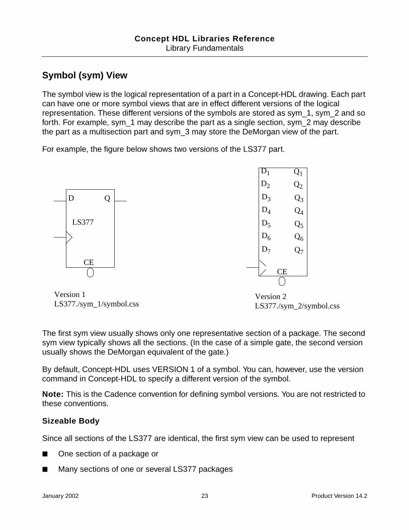
The symbol view is the logical representation of a part in a Concept-HDL drawing. Each partcan have one or more symbol views that are in effect different versions of the logicalrepresentation. These different versions of the symbols are stored as sym_1, sym_2 and soforth. For example, sym_1 may describe the part as a single section, sym_2 may describethe part as a multisection part and sym_3 may store the DeMorgan view of the part.
For example, the figure below shows two versions of the LS377 part.
The first sym view usually shows only one representative section of a package. The secondsym view typically shows all the sections. (In the case of a simple gate, the second versionusually shows the DeMorgan equivalent of the gate.)
By default, Concept-HDL uses VERSION 1 of a symbol. You can, however, use the versioncommand in Concept-HDL to specify a different version of the symbol.
Note: This is the Cadence convention for defining symbol versions. You are not restricted tothese conventions.
Sizeable Body
Since all sections of the LS377 are identical, the first sym view can be used to represent
■ One section of a package or
■ Many sections of one or several LS377 packages
D Q
LS377
CE
Version 1LS377./sym_1/symbol.css
D1
D2
D3
D4
D5
D6
D7
Q1
Q2
Q3
Q4
Q5
Q6
Q7
CE
Version 2LS377./sym_2/symbol.css
January 2002 23 Product Version 14.2

Concept HDL Libraries ReferenceLibrary Fundamentals
The VERSION 1 symbol of the LS377 is called a sizeable body. The drawing can be used torepresent multiple sections by using vectored signal names and attaching the SIZE propertyto the drawing (after it has been added to a Concept-HDL logic schematic).
Flat Symbol
The VERSION2 symbol of the LS377 shows all the logical pins of the part. This is called aflat symbol. This symbol resembles the physical package of an LS377. The LS377 packagecontains eight identical sections, and the VERSION 2 drawing shows eight input pins andeight output pins.
In most cases, the two body versions must have equivalent pin names. An exception to thisrule occurs in parts with asymmetrical sections. In this case, the versions of the part thatrepresent the different sections must have no identical pin names, so that you can distinguishthe different sections.
If a part has sections that are not interchangeable (such as the LS51), then there areadditional views that describe the additional sections. The following figure shows the differentsections of an LS51 component.
An LS51 Asymmetrical Component
January 2002 24 Product Version 14.2

Concept HDL Libraries ReferenceLibrary Fundamentals
DeMorgan Views
Some simple logic gates have versions (the DeMorgan equivalents) that represent the twodifferent logical functions performed by the gate depending on the polarity of the input signal.An LS08, for example, performs an AND operation on high-asserted signals or an ORoperation on low-asserted signals. Different versions of the LS08 allow a designer to addeither form of the gate to a drawing.
Package (chips) View
The package view or the chip view stores the package information like pin names andelectrical information for the part. This view connects the logical view of a component to itsphysical view.
The pin information like pin names, types, loading and physical numbers is stored in thechips.prt file located in chips directory.
Typical chips.prt file
FILE_TYPE=LIBRARY_PARTS;TIME=’COMPILATION ON THU JAN 10 14:52:02 1991’;primitive ‘74LS01’,’74LS01_DIP’;
pin‘B’<0>:
INPUT_LOAD=’(-0.4,0.02)’;PIN_NUMBER=’(12,9,6,3)’;PIN_GROUP=’1’;
‘A’<0>:INPUT_LOAD=’(-0.4,0.02)’;PIN_NUMBER=’(11,8,5,2)’;PIN_GROUP=’1’;
‘-Y’<0>:OUTPUT_LOAD=’(8.0,*)’;OUTPUT_TYPE=’(OC,AND)’;PIN_NUMBER=’(13,10,4,1)’;
end_pin;body
POWER_PINS=’(VCC:14;GND:7)’;FAMILY=’LSTTL’;PART_NAME=’74LS01’;BODY_NAME=’LS01’;MAX_DELAY=’10000’;DEFAULT_SIGNAL_MODEL=’SN74LS01N TI’;JEDEC_TYPE=’DIP14_3’;CLASS=’IC’;TECH=’74LS’;
end_body;end_primitive;END.
January 2002 25 Product Version 14.2
Concept HDL Libraries ReferenceLibrary Fundamentals
Entity View
This view contains the verilog.v file. This file contains the names of all the pins on thesymbol. This view is created when a symbol view is saved to the disk.
Simulation View
When a symbol view is saved to disk, an entity view is automatically created. In the entity viewis a verilog.v file that contains the names of all the pins on the symbol (known as amodule). The simulation view maps the symbol (or module) to a simulation model. The nameof the module is mapped to the name of the simulation model. The pin names in the moduleare mapped to the pin names in the simulation model. This file is sometimes called a‘wrapper’ because it contains mapping data only. The actual model is stored in an HDL modellibrary (for example, veriloglib).
During simulation, the verilog.v file in the schematic view is used as the netlist. Each partin this netlist has an entity and a simulation view.
Verilog-XL replaces the parts in the netlist with the simulation models as defined by thewrapper.
Part Table View
The part table view consists of .ptf files in the part table folder. Using this file, you cancustomize a part to fit your company needs. For example, you can add company part number,part description or any in-house or vendor information you require. A part_table view also letsyou override a property defined in the chips view. For example, you can override theJEDEC_TYPE property in the chips view with the name of another Allegro package symbolin your PCB library.
Map Views
The vlog_map, swift_map, and hw_map views have been added to the cells (whereapplicable) to support Vloglink style simulation. These views contain the verilog.map mapfile. The verilog.map file maps the signal names in the chips.prt file to the port namesin the Verilog HDL shell file (verilog.v). If you want to use Verilog-XL to simulate a design thatuses Concept symbols, you need to create a verilog.map file.
January 2002 26 Product Version 14.2
Concept HDL Libraries ReferenceLibrary Fundamentals
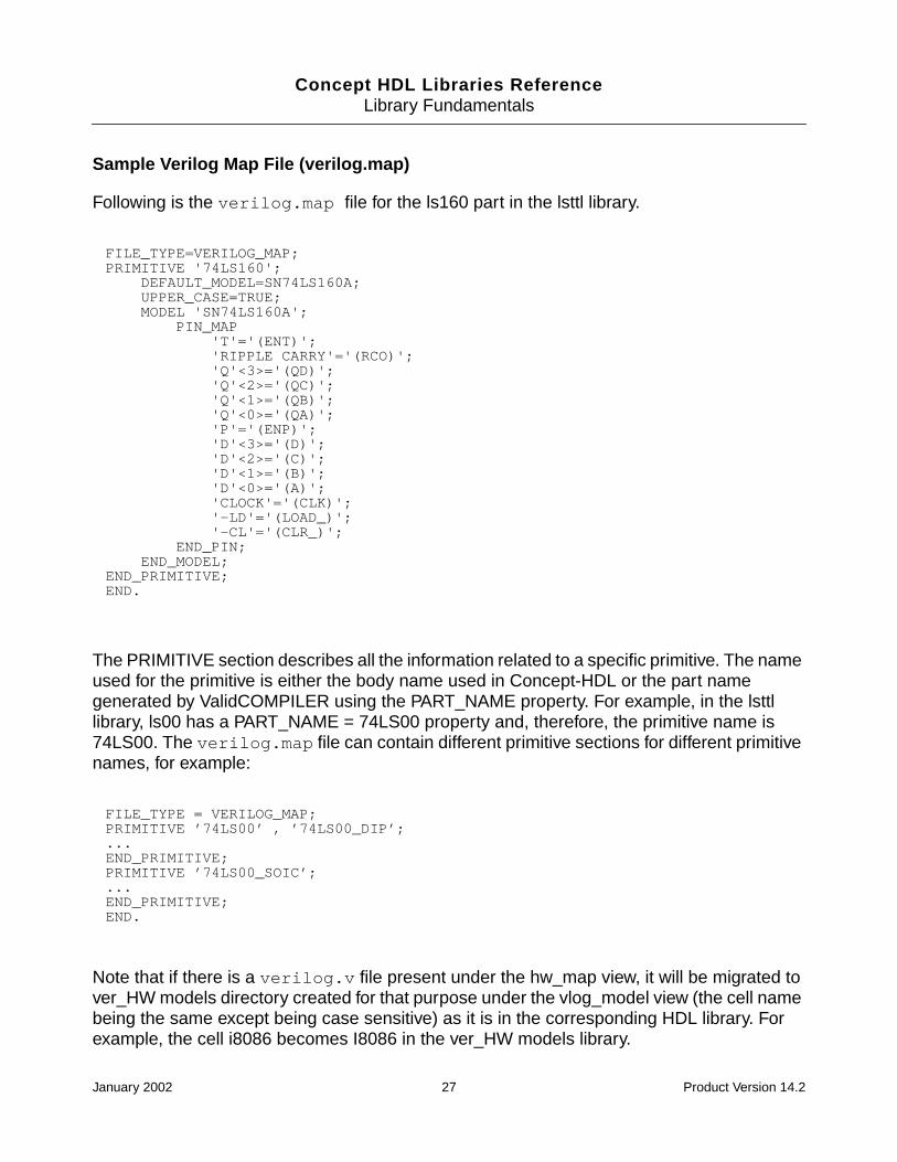
Sample Verilog Map File (verilog.map)
Following is the verilog.map file for the ls160 part in the lsttl library.
The PRIMITIVE section describes all the information related to a specific primitive. The nameused for the primitive is either the body name used in Concept-HDL or the part namegenerated by ValidCOMPILER using the PART_NAME property. For example, in the lsttllibrary, ls00 has a PART_NAME = 74LS00 property and, therefore, the primitive name is74LS00. The verilog.map file can contain different primitive sections for different primitivenames, for example:
Note that if there is a verilog.v file present under the hw_map view, it will be migrated tover_HW models directory created for that purpose under the vlog_model view (the cell namebeing the same except being case sensitive) as it is in the corresponding HDL library. Forexample, the cell i8086 becomes I8086 in the ver_HW models library.
FILE_TYPE=VERILOG_MAP;PRIMITIVE '74LS160'; DEFAULT_MODEL=SN74LS160A; UPPER_CASE=TRUE; MODEL 'SN74LS160A'; PIN_MAP 'T'='(ENT)'; 'RIPPLE CARRY'='(RCO)'; 'Q'<3>='(QD)'; 'Q'<2>='(QC)'; 'Q'<1>='(QB)'; 'Q'<0>='(QA)'; 'P'='(ENP)'; 'D'<3>='(D)'; 'D'<2>='(C)'; 'D'<1>='(B)'; 'D'<0>='(A)'; 'CLOCK'='(CLK)'; '-LD'='(LOAD_)'; '-CL'='(CLR_)'; END_PIN; END_MODEL;END_PRIMITIVE;END.
FILE_TYPE = VERILOG_MAP;PRIMITIVE ’74LS00’ , ’74LS00_DIP’;...END_PRIMITIVE;PRIMITIVE ’74LS00_SOIC’;...END_PRIMITIVE;END.
January 2002 27 Product Version 14.2
Concept HDL Libraries ReferenceLibrary Fundamentals
The Master.tag File
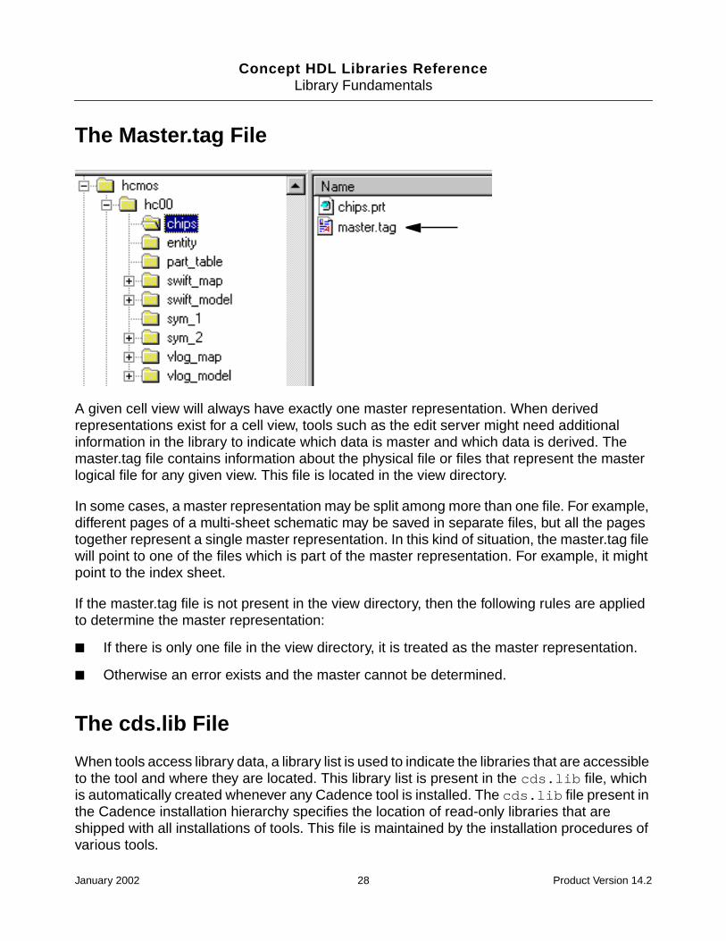
A given cell view will always have exactly one master representation. When derivedrepresentations exist for a cell view, tools such as the edit server might need additionalinformation in the library to indicate which data is master and which data is derived. Themaster.tag file contains information about the physical file or files that represent the masterlogical file for any given view. This file is located in the view directory.
In some cases, a master representation may be split among more than one file. For example,different pages of a multi-sheet schematic may be saved in separate files, but all the pagestogether represent a single master representation. In this kind of situation, the master.tag filewill point to one of the files which is part of the master representation. For example, it mightpoint to the index sheet.
If the master.tag file is not present in the view directory, then the following rules are appliedto determine the master representation:
■ If there is only one file in the view directory, it is treated as the master representation.
■ Otherwise an error exists and the master cannot be determined.
The cds.lib File
When tools access library data, a library list is used to indicate the libraries that are accessibleto the tool and where they are located. This library list is present in the cds.lib file, whichis automatically created whenever any Cadence tool is installed. The cds.lib file present inthe Cadence installation hierarchy specifies the location of read-only libraries that areshipped with all installations of tools. This file is maintained by the installation procedures ofvarious tools.
January 2002 28 Product Version 14.2

Concept HDL Libraries ReferenceLibrary Fundamentals
The cds.lib file for the Cadence supplied ConceptHDL libraries is located in the followingdirectories:
your_install_dir/share/library/
This cds.lib file contains the list of all Concept-HDL libraries that are installed on yoursystem and defines logical library names and their physical storage locations.
Sample entries in the cds.lib file located at your_install_dir/share/library/DEFINE lsttl ./lsttl
DEFINE memory ./memory
DEFINE 54alsttl ./54alsttl
DEFINE 54fact ./54fact
The verbs used in the cds.lib file to specify the library list are DEFINE, UNDEFINE, ASSIGN,UNASSIGN, INCLUDE, and SOFTINCLUDE. Verbs are case insensitive. Keywords aredistinguished from library names and paths by their position in the syntax. <lib-name> andattribute names are interpreted in the file system name space, according to the Concept-HDLname mapping specification. This means that the identifier is case sensitive and has arestricted character set.
The following commands are defined:
COMMAND EXPLANATION
DEFINE <lib-name><directory>
Causes the logical library name <lib-name> to be definedwith the ordered list of directories specified in the<directory>. Any current definition of the <lib-name> isreplaced by the new definition. It is an error if the samephysical directory is contained in multiple libraryspecifications.
UNDEFINE <lib-name> Causes the library name <lib-name> to becomeundefined. It is not an error if lib-name is not previouslydefined. This command allows you to remove unneededlibraries from browser display when the libraries aredefined in another included library list file.
INCLUDE <filename> Causes the file <filename> to be read as a cds.lib file. Thefile is interpreted immediately and, except for pathnamesrelative to the cds.lib file, the semantics are identical tothose in the contents of the file. An error is generated if thefile cannot be accessed. It is also an error if recursion isdetected in INCLUDE files.
January 2002 29 Product Version 14.2
Concept HDL Libraries ReferenceLibrary Fundamentals
cds.lib Syntax Rules
The following rules apply to the cds.lib file:
■ Only one statement per line is allowed.
■ Blank lines are allowed.
■ Use the pound sign (#) or the double hyphen ( -- ) to begin a comment. You must precedeand follow the comment character with white space, a tab, or a new line. Examples:
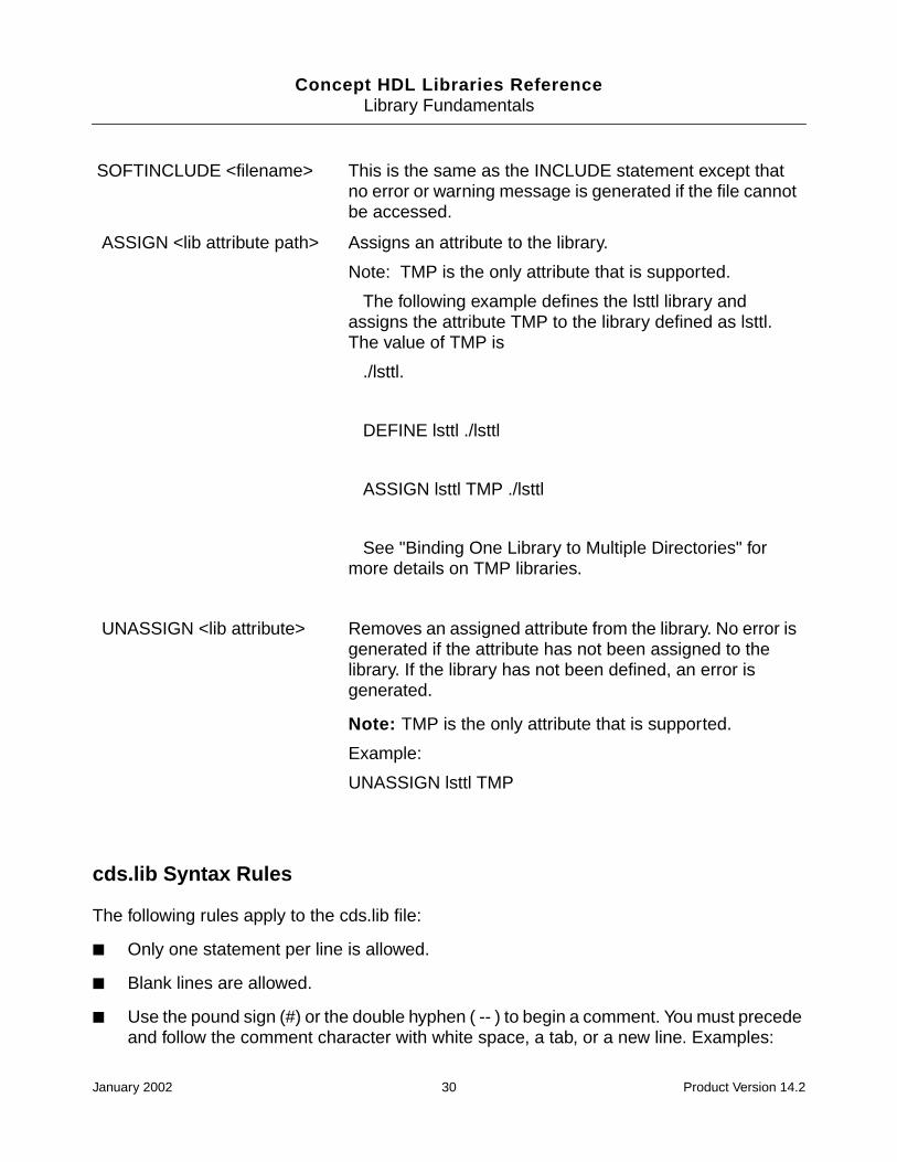
SOFTINCLUDE <filename> This is the same as the INCLUDE statement except thatno error or warning message is generated if the file cannotbe accessed.
ASSIGN <lib attribute path> Assigns an attribute to the library.
Note: TMP is the only attribute that is supported.
The following example defines the lsttl library andassigns the attribute TMP to the library defined as lsttl.The value of TMP is
./lsttl.
DEFINE lsttl ./lsttl
ASSIGN lsttl TMP ./lsttl
See "Binding One Library to Multiple Directories" formore details on TMP libraries.
UNASSIGN <lib attribute> Removes an assigned attribute from the library. No error isgenerated if the attribute has not been assigned to thelibrary. If the library has not been defined, an error isgenerated.
Note: TMP is the only attribute that is supported.
Example:
UNASSIGN lsttl TMP
January 2002 30 Product Version 14.2

Concept HDL Libraries ReferenceLibrary Fundamentals
❑ # this is a comment
❑ -- this is another comment.
■ Keywords are identified as the first non-whitespace string on a line.
■ Keywords and attributes are case insensitive.
■ You can include symbolic variables (UNIX environment variables like $HOME and CSHextensions such as ~ and ~user). Symbolic variables and library path names are in thefile system domain and are case sensitive.
■ You can enter absolute or relative file paths. Relative paths are relative to the location ofthe file in which they occur, not to the directory where the tool was invoked.
Binding One Library to Multiple Directories
You can bind a library that you have defined in the cds.lib file to a temporary storage directoryby using the ASSIGN statement to assign the TMP attribute to the library. This allows multipledesigners to reference a shared library, but store intermediate objects generated by thecompiler or by the elaborator in separate design directories. When intermediate objects areread, the tools read whatever intermediate objects they need from the original library, and, ifthe objects are not in the original library, from the TMP library.
In the following example, a library called asic_lib is defined as ${PROJECT}/asic_lib. Atemporary storage directory called work/design_lib is created, and the TMP attribute isthen assigned to asic_lib to bind this library to the temporary storage directory.
# Define the shared library
DEFINE asic_lib ${PROJECT}/asic_lib
# Assign a temp storage directory
ASSIGN asic_lib TMP ./work/design_lib
When you compile and elaborate a design that includes design units from the shared library,all new intermediate objects are stored in the TMP library instead of in the asic_lib library.Only one directory can be bound to a master library using the TMP attribute. In the cds.lib file,you must define the library before you reference it with the ASSIGN statement. If thereferenced library has not been defined before the ASSIGN statement is processed, thestatement is ignored with a warning.
Use the UNASSIGN statement to remove the TMP attribute before compiling your designunits into the master library. Many design environments include a set of shared design
January 2002 31 Product Version 14.2
Concept HDL Libraries ReferenceLibrary Fundamentals
libraries that have had their file system permissions set to read-only so that only anauthorized user can add additional design units to, or delete or move, a shared library. Whenelaborating designs that include units from these read-only libraries, the elaborator may needto produce new intermediate files for a design unit that is in a read-only library. Using anexplicit TMP library (that is, one created by assigning the TMP attribute to a library) couldsolve this problem. However, using explicit TMP libraries not only requires you to add extralines to the cds.lib file, but also opens up the possibility that design units could be accidentallyrecompiled into the TMP library, perhaps masking the contents of the shared design library.
Library Level Files
There exists two other files at the same hierarchy as the individual libraries. They are the:
■ Category Files (.cat files) on page 32
■ “Physical Part Table File (.ptf file)” on page 32
Category Files (.cat files)
There often arises a need to classify the components of a library according to some attributeof the cell, such as BUFFER, CLOCK-DISTRIBUTION etc. These sub-classifications arecalled cell categories. A cell can be in any number of categories starting from no category.Cell categories are specified in category (.cat) files.IThis is an optional file.
Physical Part Table File (.ptf file)
The Physical Parts Table (.ptf) file stores the packaging properties for a part in the library. Thisfile contains information about parts such as package types, manufacturers, part numbersand any custom properties. Each physical part must have an entry in the .ptf file in order topackage properly.
Each cell in a library containing logical parts should have a corresponding .ptf file. You canplace all of these file in a single directory which will later be read by Packager-XL duringpackaging. You should maintain packaging information such as Allegro footprint(JEDEC_TYPE), VALUE, TOLERANCE, and PWR_RATING in this file.
In some cases, you may wish to automatically generate .ptf files from an existing MRP(Material-Resource-Planning) system. Preferred parts and user part information could beextracted and used for .ptf file creation. This would ensure accurate and current information.
January 2002 32 Product Version 14.2

Concept HDL Libraries Reference
2Development Decisions and Processes
Library Development Decisions
Before you create or modify libraries, you should make some decisions that are pertinent toyour site requirements. Following are some of the issues that you should resolve:
■ Are you developing mil spec components or standard components?
■ What body standards should you follow?
■ What is the minimum size for a body or the text included within a body?
■ What tools are you currently using?
■ What tools will you be using in the future: Simulator?
■ Should you save time by creating models now for tools you might use in the future?
■ Will designers be developing their own components or will the librarian be the onlydeveloper?
■ Will the librarian test designer-developed components?
■ The standards used in this manual are for commercial components.
■ If you are building ANSI library components, you should follow the ANSI/IEEE std91-1984.
■ What are the minimum test procedures for a completed component?
Library Development Process
As a librarian, you may need to create new libraries to support your development team.Cadence provides the PCB Librarian Expert tool that enables you to successfully create andmanage libraries. However, before PCB Librarian Expert is used to create libraries and parts,it is necessary to understand the steps involved in creation of a library with new parts. Theyare:
January 2002 33 Product Version 14.2
Concept HDL Libraries ReferenceDevelopment Decisions and Processes
1. Creating the symbol view. This involves following the Cadence standards for symbolswhile specifying the schematic part symbols. For more information see:
❑ Schematic Part Symbols on page 35
❑ Standards for Symbols on page 62
2. Creating the packages, i.e creating physical models. This involves creating thechips.prt file, the part table (.ptf) file and specifying the signal property in thechips.prt file. You should follow the Cadence standards for physical information whilecreating packages. For more information see:
❑ The Chips.prt File on page 43
❑ Part Table file on page 46
❑ Signal Property in Chips View on page 45
❑ Standards for Physical Information on page 64
3. Creating the Simulation views. This involves creating the Verilog and VHDL wrappersand map views. For more information, see:
❑ Simulation Views on page 67
When designing components, the librarian must make some decisions about how to assignvalues that are not specified in the data sheets. The librarian must decide what values to useand then maintain consistency for all components in the library. Such decisions should bedocumented in a file and placed in the directory so that other users of the library can readthem.
As a general rule, permissions on component models should be set so that only the librarianor root has the permission to change the models.
January 2002 34 Product Version 14.2

Concept HDL Libraries Reference
3Cadence Digital Library Standards
Overview
As a librarian, you will need to create new libraries and parts or edit existing ones. However,before you create or edit libraries, it is important to understand the schematic part symbolsand the standards used for symbols and physical information or properties. The use of thesestandards is important for the following reasons:
■ All user-generated components will be similar to those supplied by Cadence.
■ You will gain a quicker understanding of a component, because unique symbols are usedfor multiplexers, decoders, ALUs etc.
■ You can easily migrate from one technology to another without completely redoing theschematics.
Schematic Part Symbols
The libraries supplied by Cadence should be used whenever possible. These libraries includeconsistent schematic symbols and packaging data for many commercially available parts. Allof the included underlying information is available right out of the box.
Cadence symbols consist of several elements. They include a minimum of one symbol filecalled symbol.css, which contains the graphical symbol information. Another element ofCadence schematic symbols is the chips.prt file. This file contains the logical to physical pinmapping as well as other pin and part information.
Use Part Developer whenever possible to create new parts. The default settings can be setto create usable standardized symbols and chips.prt files. These symbols can be manuallymodified to suit designers’ preferences. Since the packaging information is automaticallycreated for you, Part Developer will give you an excellent start for most symbols.
The following factors should be addressed when planning schematic symbol standards.
■ Symbol Size on page 36
January 2002 35 Product Version 14.2
Concept HDL Libraries ReferenceCadence Digital Library Standards
■ Symbol Versions on page 36
■ Pin Stubs on page 37
■ Pin to Pin Spacing on page 38
■ Pin Bubbles on page 38
■ Pin Types on page 38
■ Pin Naming on page 39
■ Pin Notes on page 40
■ Symbol Notes on page 41
■ Properties on page 41
■ Symbol Naming on page 42
■ Bussed Pins on page 42
■ The Chips.prt File on page 43
■ Signal Property in Chips View on page 45
■ Part Table file on page 46
Symbol Size
Keep the overall symbol size as small as possible while still maintaining legibility. Make theparts with size in mind. The function of the part often dictates the size of the symbol. Try andavoid making smaller logical parts too large. It is very common to end up with a two-inch tallinverter which looks out of place on the schematic.
Use the display grid in Concept-HDL to determine the symbol size. Place all pins and pinstubs on the .100 inch display grid.
Note: Be careful, the snap grid is set to .050 inch in the Concept-HDL symbol editor.
Symbol Versions
Multiple versions of parts can be built to handle a variety of situations. Here are someexamples:
■ Creating horizontal and vertical versions of parts such as resistors and capacitors allowyou to avoid getting rotated property text when the parts are rotated.
January 2002 36 Product Version 14.2
Concept HDL Libraries ReferenceCadence Digital Library Standards
Rather than rotating symbols, use alternate versions of the symbol. These alternateversions have property placeholders placed right reading and in the ideal text locations.
■ You can use multiple schematic symbols to represent a single part.
This is often the case with analog op- amps and other such parts. Each gate has aunique look and must be built separately.
■ You can functionally break out sectioned parts or parts too big to be built into one symbolinto several symbols, and package these into one device.
■ You can create different versions to enable vectored pins in one version and non-vectored pins in another.
■ You can create aesthetically different parts for functional reasons.
Test points and connector symbols can have multiple versions which represent the samepart. They can appear differently to differentiate signal direction or connector type.
■ You can create versions of DeMorgan equivalent parts to aid in part placement and toprovide correct bubbling capabilities.
Pin Stubs
Draw pin stubs .100 inch long on rectangular parts using a .100 inch visible grid. Leaving thestubs .100 inch long provides a reasonable place for the pin number annotation to appear.When the stubs are longer than .100 inch, the pin numbers appear too far away from thesymbol and look out of place.
If pin stubs utilize the ANSI standard graphic formats, longer pin stubs may be required. Keepthem as short as possible.
Draw low asserted pins with .100 inch diameter circles rather than straight-line pin stubs.When using the BUBBLE property, both graphic pin representations may be required.
Analog and odd-shaped parts should have reasonable pin stubs based on their appearance.
In most cases the default pin number locations should be adequate. The location where thepin number is to be annotated on the schematic can be preset within the symbol by placinga $PN property placeholder on each pin. The value of that property should be a questionmark (?) for a visible number or pound sign (#) for an invisible number. Verify that the text sizeof the placeholder is consistent with the design standard. Also check that the text justificationis set to right for pins on the left side of the part and left for pins on the right.
When the Concept-HDL default setup is used, vertical pin stubs result in vertical pin numbers.
January 2002 37 Product Version 14.2
Concept HDL Libraries ReferenceCadence Digital Library Standards
Pin to Pin Spacing
Establishing a minimum pin to pin space can help eliminate crowded or off-grid pins andprovides consistent readable schematics. Use the schematic wire to wire spacing minimumas the minimum pin spacing as well.
Pin spacing on bodies should be a minimum of .100 inch and should be placed on a .100 inchgrid. This spacing appears quite readable when plotted at or close to 1X scale. If theschematics get scaled in half, a .200 inch pin spacing standard should be implemented.When editing bodies in Concept-HDL, the default snap grid is .05 inch, but the visible grid is.100 inch. Pins should be placed on visible grids only. Try plotting some example sizesincluded in the supplied Cadence library parts as a baseline to see the difference clearly.
Cadence libraries are shipped with a default pin spacing of .100 inch. The client may desirea larger spacing than the one shipped in the Cadence libraries. Rather than scaling all of thesymbols in the library, you can scale the drawing formats down by a proportional amount. Youcan then plot the schematics at an increased scale to get the desired drawing size and pinspacing. You have to consider text and component size when using this approach.
Pin Bubbles
Use the BUBBLE and BUBBLE_GROUP properties for tracking and checking signal statesand circuit behavior. The pins need to be bubbled correctly while they are being designed inConcept-HDL. Symbols that are built correctly should not cause any problems and shouldsuccessfully complete the design integrity checks within Concept-HDL. These properties alsoprovide for much more readable designs when looked at logically.
Cadence libraries include the DeMorgan equivalent parts as alternate symbol versions.When placing parts, the correct symbol should be used to establish signal states and toprovide design integrity. You can use the bubble command in Concept-HDL to toggle thesignal states on pins.
Pin Types
Designate the pin types and add pin loading information in Part Developer. This informationgets stored in the chips.prt file and is crucial for some Concept-HDL integrity checks andlayout analysis with SigNoise. Signal noise analysis uses the pin type and loading informationto accurately model the behavior of components.
The information can also be input manually into the chips.prt file by using a text editor.However, this requires you to be aware of the syntax and file format.
January 2002 38 Product Version 14.2

Concept HDL Libraries ReferenceCadence Digital Library Standards
Whenever appropriate the input pins should be placed on the left side of the symbol withoutputs on the right.
Pin Naming
Pins should be designated with functional names. Each pin name must be unique to thatsymbol and must have a matching entry in the chips.prt file. Concept-HDL supports thethe following as valid pin names:
■ alphanumeric characters
■ numbers, but only for scalar pins
■ -
■ #
■ $
■ %
■ +
■ =
■ |
■ ?
■ ^
■ _
■ .
■ (
■ )
Caution
For pins that have ( or ) in their names, hlibftb reports errors if yourun verification checks from within Part Developer. However, you can usesuch pins in Concept HDL schematics by turning off themulti_format_vector option off. Because of this reason, it issuggested that you do not use ( or ) in pin names.
The following are not valid for pin names:
January 2002 39 Product Version 14.2
Concept HDL Libraries ReferenceCadence Digital Library Standards
■ All extended character sets
■ /
■ ;
■ !
■ <
■ >
■ :
■ \
■ ”
■ ,
■ *
When creating parts manually, place the SIG_NAME properties outside the symbol, next tothe pin it is attached to. Text size is not too important on these properties since they are notdisplayed on the schematic.
Follow low asserted pin names with an asterisk (*) (for example, OE*) or _N (for exampleOE_N). Do not differentiate low asserted pins with any other nomenclature. All low assertedpins should appear as bubbles and not straight pin stubs.
Pin Notes
Pin notes are used for graphical identification of pins only. In most cases, they should beplaced inside the symbol outline. The minimum text size of pin notes should be .08 inch andthey should appear next to the pin they represent. The names should accurately identify thepin functions, while remaining as short as possible. The text size should be consistent withinthe part and throughout the library.
Use the attribute command in Concept-HDL to properly set the text justification. For bestalignment, set the right side and top notes as right justified and left side and bottom notes asleft justified.
Vertical pins may be labeled with vertical text, but when possible, keep the pin note horizontaland right reading.
Low asserted pins shown with a bubbled pin stub should be labeled with a simple signal name(for example, OE). Do not use *, _L, _ or any other low asserted nomenclature in the pin note.
January 2002 40 Product Version 14.2
Concept HDL Libraries ReferenceCadence Digital Library Standards
The bubble alone differentiates this pin as low asserted. Adding another low asserted calloutcauses a double negative situation.
Note: Dual-purpose pins are the exception.
Symbol Notes
The functional part name should be placed inside the symbol when appropriate foridentification purposes. Make the text size large enough to be easily read. A recommendedtext size is .125 inches. Place any note text that aids in part identification on the part. Do notadd any unique package nomenclature such as a user internal part number or speed.
Properties
During the course of the design, several properties usually get annotated to each symbol toaid in simulation and packaging. By default, these properties get annotated in randomlocations on the part. To provide for a more readable schematic, place property placeholdersin the symbol bodies for each key property in the Physical Part Table file (.ptf). Theseplaceholders provide locations to annotate properties when placing parts in Concept-HDL inthe physical mode. Defining these placeholders in the bodies provides for much neaterschematics initially and avoids tedious property manipulation after placement.
You can control the text size and visibility by setting them properly on the placeholder. Simplyplace a property such as $PART_NUMBER on the symbol origin with a value of “?”. You canset the text location, justification and size on the “?”. The “?” will make the annotated propertyappear visible on the schematic when the part is placed. If you prefer the property to appearinvisible, make the “?” invisible in the symbol file.
Ensure that visible properties are placed outside the symbol body. This is because, when thesymbol is instantiated in the schematic, Concept-HDL aligns any instance specific propertiesthat are added with the visible properties. If a visible property is placed on the symbol body,instance specific properties that are added will overlap the symbol.
The dollar sign ($) ensures that the property is initially defined as soft. A property name withno dollar sign ($) sign differentiates it as a hard property. To avoid errors, all hard propertiesmust be defined in Concept-HDL prior to saving. Soft properties allow you to save Concept-HDL schematics without defining values for these properties. The part specifics may not beknown when entering the schematic. All part property placeholders should be defined as softproperties with a dollar sign ($).
Some properties commonly placed in symbols are
■ PART_NUMBER: Used for user or vendor part numbers
January 2002 41 Product Version 14.2

Concept HDL Libraries ReferenceCadence Digital Library Standards
■ PACK_TYPE: Used to specify package (DIP, SOIC, LCC, and so forth)
■ LOCATION: Used to specify reference designator
■ VALUE, $TOLERANCE, $PWR_RATING, $VOLTAGE etc.: Used to specify discrete partproperties
For some discrete devices such as resistors and capacitors, you may wish to make the pinnumbers appear invisible on the schematic. This is easily accomplished by placing a $PN=#property on each of the wire pin stubs in the symbol file. When the design getsbackannotated, these properties are invisible and do not clutter up the schematic.
Locate a position for each property that looks best on the schematic. Keep in mind that aminimum overall symbol size will free up room on the schematic.
Symbol Naming
When creating parts, a vendor or common (functional) part name should be used whereverpossible. Some systems require a unique part for each representation of that part. Concept-HDL has the ability to use the same logical symbol for each exact representation of a part.This eliminates having individual symbol copies available for each unique part. (For example,when you use the name LS00 as the symbol name.) Various package types and vendors canbe entered into the .ptf file along with the user internal part numbers and any other criticalpart data. Symbol names are of 0.6 Concept size or more, proportional to the size of the body(1 Concept size = 0.072 inch).
Avoid using user internal part numbers when naming symbols. Use a functional name thatwill be easier to find when scanning libraries.
Bussed Pins
Vectored pins are allowed within the Cadence libraries. These single pins represent multiplebus signals. (For example, A<7..0> represents eight bits of the A bus.) The drawback to usingthese pins is that they do not get annotated with pin numbers during packaging. The systemkeeps track of the pin numbers, but they cannot be displayed on the schematic for the finaldocumentation.
Use the option of placing schematic notes when final documentation schematics arerequired. Whenever possible, break out bussed pins into individual pins.
Always label these pins in descending bit syntax (7..0 instead of 0..7) since this is howConcept-HDL understands significant bit ordering. You could label these pins in the reverseorder as long as you are consistent with labeling. Cadence libraries are labeled in the
January 2002 42 Product Version 14.2
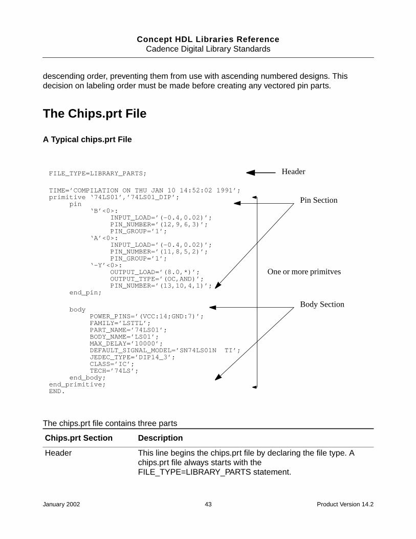
Concept HDL Libraries ReferenceCadence Digital Library Standards
descending order, preventing them from use with ascending numbered designs. Thisdecision on labeling order must be made before creating any vectored pin parts.
The Chips.prt File
A Typical chips.prt File
The chips.prt file contains three parts
Chips.prt Section Description
Header This line begins the chips.prt file by declaring the file type. Achips.prt file always starts with theFILE_TYPE=LIBRARY_PARTS statement.
FILE_TYPE=LIBRARY_PARTS;
TIME=’COMPILATION ON THU JAN 10 14:52:02 1991’;primitive ‘74LS01’,’74LS01_DIP’;
pin‘B’<0>:
INPUT_LOAD=’(-0.4,0.02)’;PIN_NUMBER=’(12,9,6,3)’;PIN_GROUP=’1’;
‘A’<0>:INPUT_LOAD=’(-0.4,0.02)’;PIN_NUMBER=’(11,8,5,2)’;PIN_GROUP=’1’;
‘-Y’<0>:OUTPUT_LOAD=’(8.0,*)’;OUTPUT_TYPE=’(OC,AND)’;PIN_NUMBER=’(13,10,4,1)’;
end_pin;
bodyPOWER_PINS=’(VCC:14;GND:7)’;FAMILY=’LSTTL’;PART_NAME=’74LS01’;BODY_NAME=’LS01’;MAX_DELAY=’10000’;DEFAULT_SIGNAL_MODEL=’SN74LS01N TI’;JEDEC_TYPE=’DIP14_3’;CLASS=’IC’;TECH=’74LS’;
end_body;end_primitive;END.
Header
One or more primitves
Pin Section
Body Section
January 2002 43 Product Version 14.2
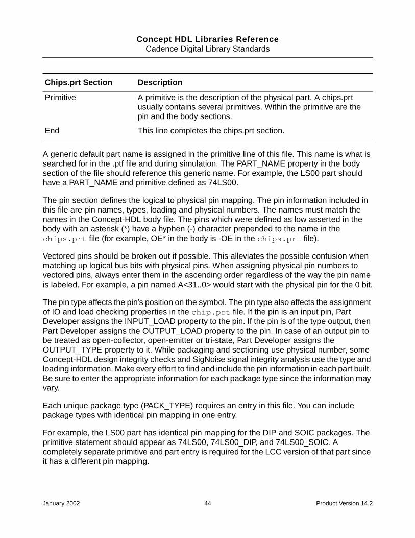
Concept HDL Libraries ReferenceCadence Digital Library Standards
A generic default part name is assigned in the primitive line of this file. This name is what issearched for in the .ptf file and during simulation. The PART_NAME property in the bodysection of the file should reference this generic name. For example, the LS00 part shouldhave a PART_NAME and primitive defined as 74LS00.
The pin section defines the logical to physical pin mapping. The pin information included inthis file are pin names, types, loading and physical numbers. The names must match thenames in the Concept-HDL body file. The pins which were defined as low asserted in thebody with an asterisk (*) have a hyphen (-) character prepended to the name in thechips.prt file (for example, OE* in the body is -OE in the chips.prt file).
Vectored pins should be broken out if possible. This alleviates the possible confusion whenmatching up logical bus bits with physical pins. When assigning physical pin numbers tovectored pins, always enter them in the ascending order regardless of the way the pin nameis labeled. For example, a pin named A<31..0> would start with the physical pin for the 0 bit.
The pin type affects the pin’s position on the symbol. The pin type also affects the assignmentof IO and load checking properties in the chip.prt file. If the pin is an input pin, PartDeveloper assigns the INPUT_LOAD property to the pin. If the pin is of the type output, thenPart Developer assigns the OUTPUT_LOAD property to the pin. In case of an output pin tobe treated as open-collector, open-emitter or tri-state, Part Developer assigns theOUTPUT_TYPE property to it. While packaging and sectioning use physical number, someConcept-HDL design integrity checks and SigNoise signal integrity analysis use the type andloading information. Make every effort to find and include the pin information in each part built.Be sure to enter the appropriate information for each package type since the information mayvary.
Each unique package type (PACK_TYPE) requires an entry in this file. You can includepackage types with identical pin mapping in one entry.
For example, the LS00 part has identical pin mapping for the DIP and SOIC packages. Theprimitive statement should appear as 74LS00, 74LS00_DIP, and 74LS00_SOIC. Acompletely separate primitive and part entry is required for the LCC version of that part sinceit has a different pin mapping.
Primitive A primitive is the description of the physical part. A chips.prtusually contains several primitives. Within the primitive are thepin and the body sections.
End This line completes the chips.prt section.
Chips.prt Section Description
January 2002 44 Product Version 14.2
Concept HDL Libraries ReferenceCadence Digital Library Standards
Use the <partname>_PACK_TYPE naming convention since Concept-HDL and Packager-XL understand this convention. The .ptf file for this part should have a key property calledPACK_TYPE with DIP, SOIC and LCC entries. For more details on the .ptf files, see Part Tablefile on page 46.
If a PART_NAME property is placed in the chips.prt file, it must have a matching primitiveentry. Failing to have this condition causes packaging errors.
The JEDEC_TYPE property maps the Concept symbol to the Allegro package symbol. Thisproperty is the link between Concept and Allegro libraries.
The BODY_NAME property has the same value as the cell name. Packager uses thisproperty to create a backannotate file (pstback.dat).Archiver reads a schematic designand copies the library files into an archive library (so it can be stored with the design). TheArchiver uses the BODY_NAME property in the chips.prt file to locate a reference cell.
When this property is not defined in the chips.prt file, Packager and Archiver will use thePART_NAME property instead.
For technology dependent libraries, cell and part names are the same. For example, the cellname is 74LVT574 and so is the part name. Therefore, the BODY_NAME property is notneeded.
For technology independent libraries, cell and part names will not be the same. For example,the cell name is 574 and the part name is 74LVT574. Therefore in these cases, theBODY_NAME property will be needed.
In summary, the chips.prt file contains physical pin numbers and pin information. Makesure you verify the completed file against the vendor specification before making the partavailable to designers. Since this involves manually inputting data from a paper specification,this is the most probable area for errors to surface. You should always double-check for errors.
Comments in the chips.prt File
You can add comments in the chips.prt file by entering the text between { and }.
Signal Property in Chips View
The chips.prt file has an additional property -- the signal model property -- which gives ita default association with the Signal Integrity device model.
January 2002 45 Product Version 14.2

Concept HDL Libraries ReferenceCadence Digital Library Standards
In the absence of any Signal Integrity device model, and an annotation with a part in theschematic, the default signal model gets associated. This would allow designers to test thedesign at the backend for signal integrity with the Analysis tool.
Each primitive section in chips.prt will have the additional property of chips.prt,provided the default signal model exists in the Signal Library (provided by Zeelan). Theproperty also indicates a default manufacturer of the device for which the Signal Integritymodel was developed.
It has to be noted that no such property would exist in the absence of a model for that part inthe Zeelan Library.
An example of the chips.prt section having the signal model property body is given below:
POWER_PINS='(VCC:14;GND:7)';
FAMILY='LSTTL';
PART_NAME='74LS00';
BODY_NAME='LS00';
DEFAULT_SIGNAL_MODEL='SN74LS00D TI';
JEDEC_TYPE='SOIC14';
CLASS='IC';
TECH='74LS';
end_body;
Part Table file
The Physical Parts Table (.ptf) file stores the packaging properties for a part in the library. Thisfile contains information about parts such as package types, manufacturers, part numbersand any custom properties. Each physical part must have an entry in the .ptf file in order topackage properly.
January 2002 46 Product Version 14.2

Concept HDL Libraries ReferenceCadence Digital Library Standards
For example, displayed below is a typical entry from a .ptf file
In the above part table file:
■ A unique part number is assigned based on package style.
■ An Allegro package symbol name is assigned based on package style.
Note: The JEDEC_TYPE property may also be defined in the chips.prt file. However, thepart_table view has the priority.
■ A part description is added
The PACK_TYPE property is a key property (its’s on the left hand side of the equal sign). Thisimplies that every 74LVT574 in the schematic must have the PACK_TYPE property assigned.However, if an 74LVT574 is found that does not have a PACK_TYPE property value of eitherDIP, SOIC or LCC, the Packager will abort. To set a default PACK_TYPE value, use the OPTstatement as follows:
:PACK_TYPE (OPT = ‘LCC’) = PART_NUMBER | JEDEC_TYPE | DESCRIPTION;
When a 74LVT574 part in the schematic fits the key property description (has a PACK_TYPEproperty value of either DIP, SOIC or LCC), then the injected properties (they are all on theright side of the equal sign) are added to the packager netlist files (specifically thepstchip.dat file).
Each cell in a library containing logical parts should have a corresponding .ptf file. You canplace all of these file in a single directory which will later be read by Packager-XL duringpackaging. You should maintain packaging information such as Allegro footprint(JEDEC_TYPE), VALUE, TOLERANCE, and PWR_RATING in this file.
FILE_TYPE = MULTI_PHYS_TABLE;
PART ‘74LVT574’
CLASS = IC
:PACK_TYPE = Part_NUMBER | JEDEC_TYPE | DESCRIPTION;
DIP = CDS123 | DIP20_3 | FLIP_FLOP
SOIC = CDS456 | SOIC20 | FLIP-FLOP
LCC = CDS789 | LCC20 | FLIP-FLOP
END_PART
END.
January 2002 47 Product Version 14.2
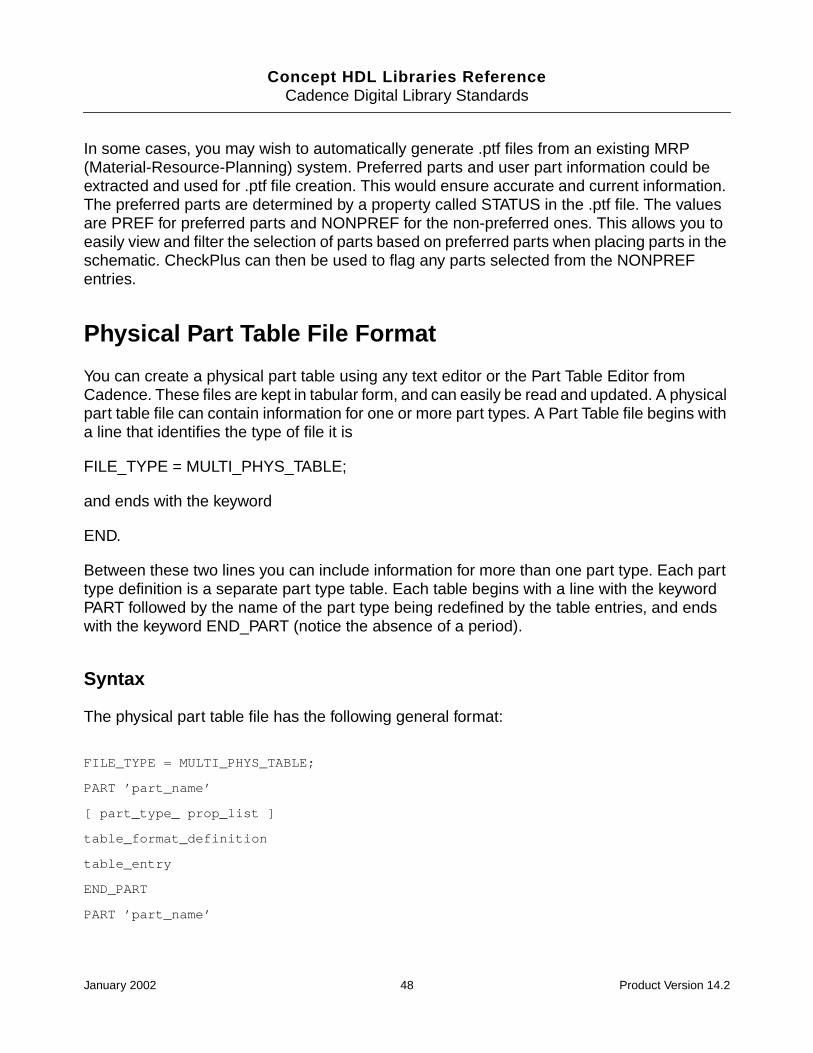
Concept HDL Libraries ReferenceCadence Digital Library Standards
In some cases, you may wish to automatically generate .ptf files from an existing MRP(Material-Resource-Planning) system. Preferred parts and user part information could beextracted and used for .ptf file creation. This would ensure accurate and current information.The preferred parts are determined by a property called STATUS in the .ptf file. The valuesare PREF for preferred parts and NONPREF for the non-preferred ones. This allows you toeasily view and filter the selection of parts based on preferred parts when placing parts in theschematic. CheckPlus can then be used to flag any parts selected from the NONPREFentries.
Physical Part Table File Format
You can create a physical part table using any text editor or the Part Table Editor fromCadence. These files are kept in tabular form, and can easily be read and updated. A physicalpart table file can contain information for one or more part types. A Part Table file begins witha line that identifies the type of file it is
FILE_TYPE = MULTI_PHYS_TABLE;
and ends with the keyword
END.
Between these two lines you can include information for more than one part type. Each parttype definition is a separate part type table. Each table begins with a line with the keywordPART followed by the name of the part type being redefined by the table entries, and endswith the keyword END_PART (notice the absence of a period).
Syntax
The physical part table file has the following general format:
FILE_TYPE = MULTI_PHYS_TABLE;
PART ’part_name’
[ part_type_ prop_list ]
table_format_definition
table_entry
END_PART
PART ’part_name’
January 2002 48 Product Version 14.2

Concept HDL Libraries ReferenceCadence Digital Library Standards
.
.
.
END_PART
END.
The figure below shows a generalized picture of a physical part table file, along with theformat of an individual part type table.
The subsections that follow provide detailed syntax information on the format of a part typetable. Each line marked with a bullet in the part type table outline below corresponds to asubsection that follows.
FILE_TYPE = MULTI_PHYS_TABLEpart type table...part type tableEND.
PART ‘part name’part type property listtable format definitiontable entriesEND_PART
PART ‘part name’part type property listtable format definitiontable entriesEND_PART
January 2002 49 Product Version 14.2

Concept HDL Libraries ReferenceCadence Digital Library Standards
PART ‘part_name’
The physical part name of the component being redefined by the table entries. Thepart_name must be enclosed in single quotes.
Part_Type Property_List
You use this section of the part tables to add new properties to all instances of a part typewithout having to modify the physical information files or library drawings.
There can be any number of property name/value entries, but there can be only one entry perline.
If a property does not fit on one line, use a tilde (~) as a continuation character. The ~ canappear between any two characters in a line but must be the last character in the line.
For example, this entry is read as if it were all on one line:
CLASS = DIS~
CRETE
Multiple spaces in a line are read as one space. Leading and trailing spaces around propertyvalues are removed. If leading or trailing spaces are required, surround the property valueswith single or double quotes:
part_type_ property_list This is useful when you want to add properties independentof any set of properties attached to a logical part. Thepart_type_ property_list follows the format:
property_name = property_value
property_name A standard HDL property. It is a string of nomore than 16 alphanumeric characters,beginning with an alphabetic character. Theunderscore (_) is considered analphanumeric character.
property_value Any string of characters, terminated by theend of the line.
January 2002 50 Product Version 14.2

Concept HDL Libraries ReferenceCadence Digital Library Standards
CLASS = ’ DISCRETE ’
You can include a quote mark in a quoted string by doubling it when used:
HOW_ARE_YOU = ’I’’m OK’
Table Format Definition
This line defines the format of each table entry that follows.
table_format_definition
The table_ format_definition uses the format:
: prop_name [(OPT=’def’ )] [separator prop_name ...] = prop_name [separatorprop_name ...] ;
The left-hand side of the table_format_definition describes the key property namesthat are attached to an instance of the part on the schematic. These properties control theselection and customization of the part. More than one property can be specified andproperty definitions can span several lines.
For example, the following definition specifies that the VALUE property is optional on the part:
: VALUE(OPT=’1K’) = PART_NUMBER;
If the VALUE property is not present on the part, the Packager assumes a default value of 1Kand does not generate any warning messages.
If more than one property is specified, all properties must match the values as specified inthe table before the part entry is selected.
The following figure shows a physical part table with two properties specified. For each partinstance, both VALUE and TOLERANCE must match the specified values before the entry is
prop_name A standard property name
OPT Defines whether a property is optional on an instance of a part.
‘def’ The default value for the property if it is not present on an instance of thepart. The default value must be enclosed in single quotes. If the defaultvalue is not included, Packager-XL uses the first entry in the table thatmatches the other key properties.
January 2002 51 Product Version 14.2

Concept HDL Libraries ReferenceCadence Digital Library Standards
selected. In this case, changing the TOLERANCE property on a 1K resistor selects a differentpart (with a corresponding change in cost).
separator
If your instance property list or part property list contains more than one entry, you mustchoose a separator character. You indicate your choice of separator character simply by usingan eligible character in your definition. Your character choice as a separator eliminates theuse of that character in expressing a property value. You may use the same separatorcharacter in the instance and part property lists or define a different character for each list.
A separator may be any keyboard character (including a space or multiple spaces) that doesnot have a conflicting definition. It cannot be a letter, a digit, or any of the following specialcharacters:
( ) Opening and closing parentheses, which delimit attributes
{ } Opening and closing braces, which delimit comments
[ ] Opening and closing square brackets, which enclose a range for an R attribute.These characters are ineligible only when the R attribute is used.
= Equal sign, which is an assignment character
: Colon, which introduces the table format definition
; Semicolon, which is a statement terminator
‘ “ Quote marks (single or double), which indicate that spaces should beinterpreted literally
_ Underscore, which is interpreted just as a letter or number
~ Tilde, which is a continuation character
File_Type = MULTI_PHYS_TABLE;
PART ‘1/4W RES’
: VALUE, TOLERANCE = PART_NUMBER COST;
1K, 5% = CB1025 $0.05
1k, 1% = CB1021 $0.50
1.2k, 5% = CB1225 $0.05
1.2K, 1% = CB1221 $0.50
END_PART
END
January 2002 52 Product Version 14.2
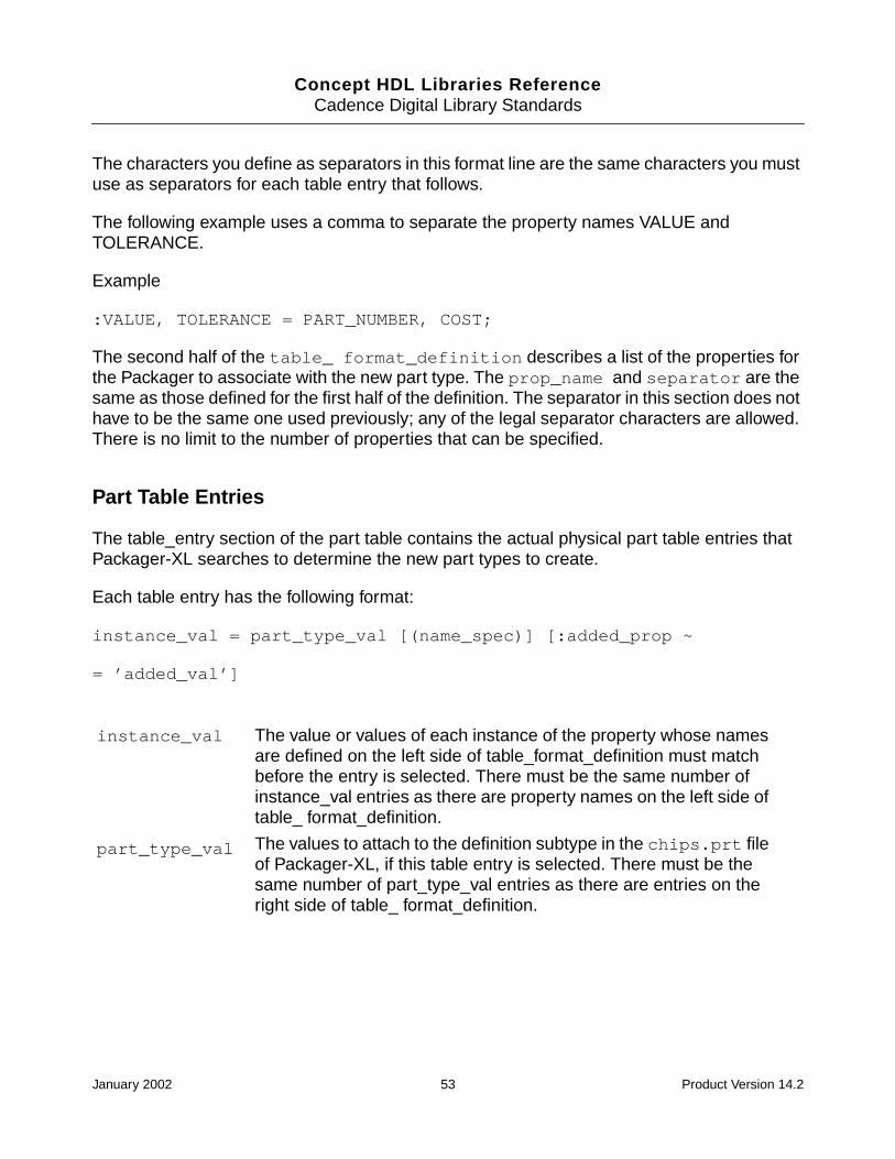
Concept HDL Libraries ReferenceCadence Digital Library Standards
The characters you define as separators in this format line are the same characters you mustuse as separators for each table entry that follows.
The following example uses a comma to separate the property names VALUE andTOLERANCE.
Example
:VALUE, TOLERANCE = PART_NUMBER, COST;
The second half of the table_ format_definition describes a list of the properties forthe Packager to associate with the new part type. The prop_name and separator are thesame as those defined for the first half of the definition. The separator in this section does nothave to be the same one used previously; any of the legal separator characters are allowed.There is no limit to the number of properties that can be specified.
Part Table Entries
The table_entry section of the part table contains the actual physical part table entries thatPackager-XL searches to determine the new part types to create.
Each table entry has the following format:
instance_val = part_type_val [(name_spec)] [:added_prop ~
= ’added_val’]
instance_val The value or values of each instance of the property whose namesare defined on the left side of table_format_definition must matchbefore the entry is selected. There must be the same number ofinstance_val entries as there are property names on the left side oftable_ format_definition.
part_type_val The values to attach to the definition subtype in the chips.prt fileof Packager-XL, if this table entry is selected. There must be thesame number of part_type_val entries as there are entries on theright side of table_ format_definition.
January 2002 53 Product Version 14.2

Concept HDL Libraries ReferenceCadence Digital Library Standards
added_ prop entries are only used when you need to add new properties for the part typecreated for this table entry.
The figure below shows a physical part table that defines a new property value. Part typescreated for resistors with a VALUE of 1K, a PART_NUMBER of CB1025, and a COST of $0.05will also have a TOLERANCE of 5%. Resistors with a VALUE of 1.2K or 1.5K will not havethe TOLERANCE property added to the new part type.
name_spec The new part subtype name specification for this table entry. This isan optional item in the table entry. name_spec can follow thesethree forms:
■ !
■ subtype_name_suffix
■ ~complete_user_subtype_name
See Part Subtype Names for an explanation of the valuesname_spec can take
added_ prop A list of properties that are added to this part. This allows you toadd properties to specific parts without having to redefine the tableformat for all parts. Each added_ prop must be a standard SCALDproperty name. Commas must separate multiple properties.
‘added_val’ The property value to match added_ prop. The value must beenclosed in single quotes.
FILE_TYPE = MULTI_PHYS_TABLE;
PART ‘1/4W RES’
:VALUE = PART_NUMBER, COST;
1K = CB1025, $0.05: TOLERANCE = ‘=5%’
1.2K = CB1225, $0.05
1.5K = CB1525, $0.05
END_PART
END.
January 2002 54 Product Version 14.2
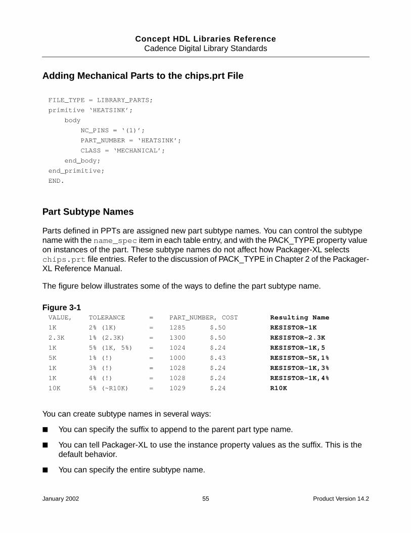
Concept HDL Libraries ReferenceCadence Digital Library Standards
Adding Mechanical Parts to the chips.prt File
Part Subtype Names
Parts defined in PPTs are assigned new part subtype names. You can control the subtypename with the name_spec item in each table entry, and with the PACK_TYPE property valueon instances of the part. These subtype names do not affect how Packager-XL selectschips.prt file entries. Refer to the discussion of PACK_TYPE in Chapter 2 of the Packager-XL Reference Manual.
The figure below illustrates some of the ways to define the part subtype name.
Figure 3-1
You can create subtype names in several ways:
■ You can specify the suffix to append to the parent part type name.
■ You can tell Packager-XL to use the instance property values as the suffix. This is thedefault behavior.
■ You can specify the entire subtype name.
FILE_TYPE = LIBRARY_PARTS;
primitive ‘HEATSINK’;
body
NC_PINS = ‘(1)’;
PART_NUMBER = ‘HEATSINK’;
CLASS = ‘MECHANICAL’;
end_body;
end_primitive;
END.
VALUE, TOLERANCE = PART_NUMBER, COST Resulting Name
1K 2% (1K) = 1285 $.50 RESISTOR-1K
2.3K 1% (2.3K) = 1300 $.50 RESISTOR-2.3K
1K 5% (1K, 5%) = 1024 $.24 RESISTOR-1K,5
5K 1% (!) = 1000 $.43 RESISTOR-5K,1%
1K 3% (!) = 1028 $.24 RESISTOR-1K,3%
1K 4% (!) = 1028 $.24 RESISTOR-1K,4%
10K 5% (~R10K) = 1029 $.24 R10K
January 2002 55 Product Version 14.2
Concept HDL Libraries ReferenceCadence Digital Library Standards
Automatic Subtype Names
If you leave name_spec out of the table entry, Packager-XL uses the instance property valuesas the suffix.
User-Defined Suffixes
If you put a string of text between the parentheses in the name_spec, Packager-XL puts adash in front of the string and appends it to the parent part type name. Lines 2-4 of Figure 3-1on page 55 use this method.
Instance Property Value Suffixes
If you use an exclamation point (!) as the name_spec, Packager-XL constructs a suffix for theparent part type from the value(s) of the instance property or properties (the property valuesthat tell Packager-XL which table entry to use for each instance). Lines 5 and 6 of Figure 3-1on page 55 use this method.
Thus, for all three of the suffixes above, the part subtype names follow the form
parent_partname[ _PACK_TYPE]-suffix
Characters Allowed in a Suffix
The characters that are allowed in a subtype suffix are all letters and digits and the followingspecial characters:
, $ % # & * + _ .
The PART_TYPE_LENGTH directive controls the subtype name length limit. The length of thepart type and the suffix together cannot exceed the value of the PART_TYPE_LENGTH option,which has a maximum value of 255. If the names are longer than this limit, these names aretruncated.
If no suffix is specified, Packager-XL uses the instance property values as the suffix.
Complete User Subtype Names
If you use a tilde (~) followed by a string of text, the packager uses that name as the name ofthe new part. The name is arbitrary, and need not contain or even resemble the parent parttype name. Line 8 of Figure 3-1 on page 55 uses this method.
January 2002 56 Product Version 14.2

Concept HDL Libraries ReferenceCadence Digital Library Standards
Names from the PACK_TYPE Property Value
Suppose your organization screens LM741 op amps by hand to select low-noise parts, andthat you use LM741s in several different packages. You might attach a propertyLONOISE=TRUE in the schematic to the instances of the part that must be the special low-noise versions. Your part table file would be as follows:
The packager would produce part subtype names like:
■ LM741_DIP-LONOISE
■ LM741_DIP-NOISY
■ LM741_SMD-LONOISE
Here is another example. Consider the part table displayed below:
If there is an instance of a 74LS00 with values of 1, 2, and 3 for the properties A, B, and Crespectively, Packager-XL creates the subtype name MODIFIED_74LS00 and gives the partthe properties PART_NUMBER=001 and COST=30, with the pinouts of the 74LS00 entry inthe chips.prt file.
If there is an instance of the 74LS00 with values of 4, 5, and 6 for A, B, and C, and theproperties PACK_TYPE=DIP and PART_NAME=74LS00, Packager-XL creates a subtype
FILE_TYPE = MULTI_PHYS_TABLE;
PART ‘LM741’
: LOWNOISE
TRUE (LONOISE) = $1.50
FALSE (NOISY) = $0.75
END_PART
END.
FILE_TYPE = MULTI_PHYS_TABLE;
PART ‘74LS00’
:A,B,C = PART_NUMBER, COST;
1, 2, 3, (~MODIFIED 74LS00) = 001, 30
4, 5, 6, (~74LS00NEW) = 002, 40
END_PART
END.
January 2002 57 Product Version 14.2
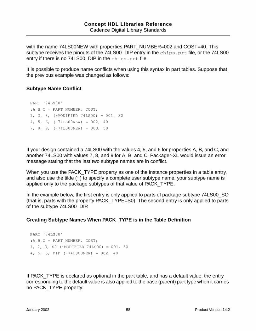
Concept HDL Libraries ReferenceCadence Digital Library Standards
with the name 74LS00NEW with properties PART_NUMBER=002 and COST=40. Thissubtype receives the pinouts of the 74LS00_DIP entry in the chips.prt file, or the 74LS00entry if there is no 74LS00_DIP in the chips.prt file.
It is possible to produce name conflicts when using this syntax in part tables. Suppose thatthe previous example was changed as follows:
Subtype Name Conflict
If your design contained a 74LS00 with the values 4, 5, and 6 for properties A, B, and C, andanother 74LS00 with values 7, 8, and 9 for A, B, and C, Packager-XL would issue an errormessage stating that the last two subtype names are in conflict.
When you use the PACK_TYPE property as one of the instance properties in a table entry,and also use the tilde (~) to specify a complete user subtype name, your subtype name isapplied only to the package subtypes of that value of PACK_TYPE.
In the example below, the first entry is only applied to parts of package subtype 74LS00_SO(that is, parts with the property PACK_TYPE=S0). The second entry is only applied to partsof the subtype 74LS00_DIP.
Creating Subtype Names When PACK_TYPE is in the Table Definition
If PACK_TYPE is declared as optional in the part table, and has a default value, the entrycorresponding to the default value is also applied to the base (parent) part type when it carriesno PACK_TYPE property:
PART ‘74LS00’
:A,B,C = PART_NUMBER, COST;
1, 2, 3, (~MODIFIED 74LS00) = 001, 30
4, 5, 6, (~74LS00NEW) = 002, 40
7, 8, 9, (~74LS00NEW) = 003, 50
PART ‘74LS00’
:A,B,C = PART_NUMBER, COST;
1, 2, 3, S0 (~MODIFIED 74LS00) = 001, 30
4, 5, 6, DIP (~74LS00NEW) = 002, 40
January 2002 58 Product Version 14.2

Concept HDL Libraries ReferenceCadence Digital Library Standards
Creating Subtype Names When PACK_TYPE is in the Table Definition
In the above figure, the first entry is applied to instances of the 74LS00 withPACK_TYPE=SO. The second entry is applied to instances with no PACK_TYPE property,and to instances with PACK_TYPE=DIP.
If the chips.prt file entries for 74LS00 and the version with PACK_TYPE=DIP are different,the packager would report an error if the design contains 74LS00s both with and without thePACK_TYPE=DIP property. The error occurs because both parts map to the same subtypename, 74LS00-NEW, but have different chips.prt file entries (different pinouts).
Sample Physical Part Table
The table below shows an example of a physical part table for 1/4-watt resistors. Commentsare enclosed in braces and precede the element they describe. The line numbers on the leftare not actually part of the file. They are used to describe the format of the table.
Line 1 Starts the physical part table file and tells Packager-XL that thefile is a multiple physical part table file. It can contain more thanone part type.
Lines 2 through 4 Separates the first line from the lines that follow. Packager-XLignores blank lines and comment lines, but these lines make thefile more easy to read. Comments are enclosed by curly braces ({ } ). Comments can cross line boundaries, but they cannot benested.
Line 5 Starts the physical part table entries for the 1/4W RES part type.The part type name must be enclosed in single quotes. Eithersingle or double quote marks are required if the part nameincludes spaces.
Lines 9 and 10 Indicate that all 1/4-watt resistors have the body propertiesCLASS and JEDEC_TYPE added to the part type, with thevalues DISCRETE and CR1/4W respectively.
PART ‘74LS00’
:A,B,C PACK_TYPE (OPT = ‘DIP’) = PART_NUMBER, COST;
1, 2, 3, S0 (~MODIFIED 74LS00) = 001, 30
4, 5, 6, DIP (~74LS00NEW) = 002, 40
January 2002 59 Product Version 14.2
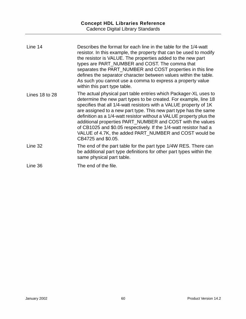
Concept HDL Libraries ReferenceCadence Digital Library Standards
Line 14 Describes the format for each line in the table for the 1/4-wattresistor. In this example, the property that can be used to modifythe resistor is VALUE. The properties added to the new parttypes are PART_NUMBER and COST. The comma thatseparates the PART_NUMBER and COST properties in this linedefines the separator character between values within the table.As such you cannot use a comma to express a property valuewithin this part type table.
Lines 18 to 28 The actual physical part table entries which Packager-XL uses todetermine the new part types to be created. For example, line 18specifies that all 1/4-watt resistors with a VALUE property of 1Kare assigned to a new part type. This new part type has the samedefinition as a 1/4-watt resistor without a VALUE property plus theadditional properties PART_NUMBER and COST with the valuesof CB1025 and $0.05 respectively. If the 1/4-watt resistor had aVALUE of 4.7K, the added PART_NUMBER and COST would beCB4725 and $0.05.
Line 32 The end of the part table for the part type 1/4W RES. There canbe additional part type definitions for other part types within thesame physical part table.
Line 36 The end of the file.
January 2002 60 Product Version 14.2

Concept HDL Libraries ReferenceCadence Digital Library Standards
Sample Physical Part Table
1 FILE_TYPE = MULTI_PHYS_TABLE;
2
3 ( 1/4-watt resistor table )
4
5 PART ‘1/4 W RES’
6
7 ( part_type_prop_list (ALLEGRO specific props )
8
9 CLASS = DISCRETE
10 JEDEC_TYPE = CR1/4W
11
12 ( table_format_definition )
13
14 : VALUE = PART_NUMBER, COST;
15
16 (table_entry section - resistors )
17
18 1K = CB1025, $0.05
19 1.2K = CB1225, $0.05
20 1.5K = CB1525, $0.05
21 2.2K = CB2225, $0.05
22 2.7K = CB2725, $0.05
23 3.3K = CB3325, $0.05
24 3.9K = CB3925, $0.05
25 4.7K = CB4725, $0.05
26 5.6K = CB5625, $0.05
27 6.8K = CB6825, $0.05
28 8.2K = CB8225, $0.05
29
30 ( end of the 1/4 W RES entries)
31
32 END_PART
33
34 ( end of the physical part table file )
35
36 END.
January 2002 61 Product Version 14.2

Concept HDL Libraries ReferenceCadence Digital Library Standards
Standards for Symbols
The symbols can be created using Concept-HDL. However, you should use the PartDeveloper tool for generating rectangular symbols that have a large number of pins (forexample, VLSI devices). The following are the standards that Cadence uses for creatingconventional symbols:
■ All bodies are drawn using a grid spacing of 0.05 2 grid (grid points are 0.05 inches apartand grid lines are at 0.1 inches interval).
■ Connections to slant or circular bodies and placement of notes are done using 0.01 10grid.
■ By keeping the origin at the center of the body, bodies are drawn symmetrically.
■ Input and output pins are placed such that the body has a balanced look.
■ Input pins are placed at the left and output and I/O pins are placed on the right.
■ Some control pins such as enable, set, and reset may be placed at the top or bottom.
■ All pins are placed on visible grid lines (0.1 inch apart).
■ In some cases, it is necessary to place an output pin between the grid lines but thesepins are still on grid points. These are connected to the body with a 0.1-inch wire (forhigh-asserted pins), a circle of 0.1-inch diameter (for low-asserted pins).
■ Pin names and notes are selected according to the data book information.
■ When names are different in different manufacturers data books, a common name isselected, which can be recognized quickly by the hardware engineers. These names arethen used consistently across all similar parts and libraries. The pin names conform tothe Cadence signal syntax.
■ Pin names are placed on the same grid nearer to the pin.
■ Bottom and top pin names are arranged without overlapping.
■ The shape of the body will generally indicate the function of the part as closely aspossible.
■ Gates have a height of 0.3 inches with a 0.6 inch spacing between input and output pins.
■ Where functions of pins are obvious, no notes are placed inside the gates.
■ All text (properties, signal names, notes, and so on) is entered in uppercase letters.
■ Body names are selected to match the part being developed with technology (LS forLSTTL), revision, speed, and manufacturer name (for unique parts).
January 2002 62 Product Version 14.2
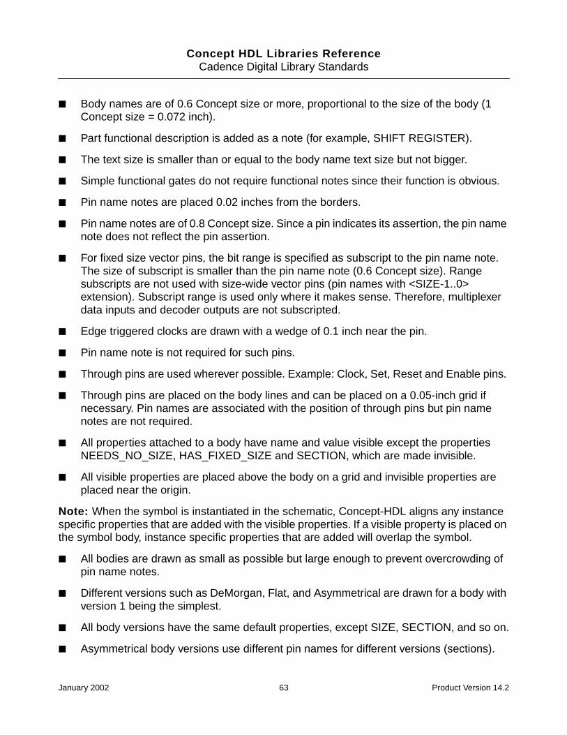
Concept HDL Libraries ReferenceCadence Digital Library Standards
■ Body names are of 0.6 Concept size or more, proportional to the size of the body (1Concept size = 0.072 inch).
■ Part functional description is added as a note (for example, SHIFT REGISTER).
■ The text size is smaller than or equal to the body name text size but not bigger.
■ Simple functional gates do not require functional notes since their function is obvious.
■ Pin name notes are placed 0.02 inches from the borders.
■ Pin name notes are of 0.8 Concept size. Since a pin indicates its assertion, the pin namenote does not reflect the pin assertion.
■ For fixed size vector pins, the bit range is specified as subscript to the pin name note.The size of subscript is smaller than the pin name note (0.6 Concept size). Rangesubscripts are not used with size-wide vector pins (pin names with <SIZE-1..0>extension). Subscript range is used only where it makes sense. Therefore, multiplexerdata inputs and decoder outputs are not subscripted.
■ Edge triggered clocks are drawn with a wedge of 0.1 inch near the pin.
■ Pin name note is not required for such pins.
■ Through pins are used wherever possible. Example: Clock, Set, Reset and Enable pins.
■ Through pins are placed on the body lines and can be placed on a 0.05-inch grid ifnecessary. Pin names are associated with the position of through pins but pin namenotes are not required.
■ All properties attached to a body have name and value visible except the propertiesNEEDS_NO_SIZE, HAS_FIXED_SIZE and SECTION, which are made invisible.
■ All visible properties are placed above the body on a grid and invisible properties areplaced near the origin.
Note: When the symbol is instantiated in the schematic, Concept-HDL aligns any instancespecific properties that are added with the visible properties. If a visible property is placed onthe symbol body, instance specific properties that are added will overlap the symbol.
■ All bodies are drawn as small as possible but large enough to prevent overcrowding ofpin name notes.
■ Different versions such as DeMorgan, Flat, and Asymmetrical are drawn for a body withversion 1 being the simplest.
■ All body versions have the same default properties, except SIZE, SECTION, and so on.
■ Asymmetrical body versions use different pin names for different versions (sections).
January 2002 63 Product Version 14.2

Concept HDL Libraries ReferenceCadence Digital Library Standards
■ Wherever possible, the bubble group property is used to avoid more versions of the body.
Standards for Physical Information
Physical information or properties is contained in the chips.prt file. For parts with a smallpin count, you can create this file using any text editor. However for complex parts that havea large number of pins, you should use the Cadence Part Developer to create the chips.prtfile. When you use the Cadence Part Developer, you do not need to know the syntax of thechips.prt file.
The standards that Cadence uses when creating the chips.prt file are as follows:
■ The primitive statement in the first section lists the default package and also the mostcommon package of the part (for example, primitive 74LS00, 74LS00_DIP).
■ Identical packages can share the same physical information by including all suchpackages in the same primitive statement. The packager needs to have the sameJEDEC_TYPE (Allegro outline for the part), for example, 54LS00, 54LS00_DIP,54LS00_CERDIP.
■ The chips.prt file can have multiple sections for different packages (for example, DIP,SOIC, LCC, and so on).
■ The pin section of the chips.prt file contains the following pin properties:
Pin Properties Description
PIN_NAME PIN_NAME is the same as the name for the corresponding pinin the Concept HDL drawing, except for low asserted pins. Forlow asserted pins, the asterisk is replaced with a - sign beforethe pin name. Also, suffix <SIZE-1..0> in a Concept-HDL bodydrawing is replaced by <0> in the chips.prt file.
PIN_NUMBER The pin number can be any alphanumeric character includingthe underscore character. The maximum length of a pinnumber is 16 characters. Also, the pin number sequence isfrom MSB to LSB.
PIN_GROUP This property is attached to all swappable pins.
INPUT_LOAD Part Developer assigns this property to an input pin. The inputlocal current is measured in milliamperes.
OUTPUT_LOAD Part Developer assigns this property to an output pin. This ismeasured in milliamperes.
January 2002 64 Product Version 14.2

Concept HDL Libraries ReferenceCadence Digital Library Standards
■ The body section of the chips.prt file contains the following properties:
OUTPUT_TYPE Part Developer assigns this property to define an output pin asopen collector, open-emitter or, tri-state. This data is used tomake sure all outputs on a net have the same output type. TheOUTPUT_TYPE property also specified the logic functioncreated by tying the outputs together.
BIDIRECTIONAL Use this property to determine a pin as bidirectional.Bidirectional pins have both input and output load properties.Bidirectional pins also have the property BIDIRECTIONAL =TRUE. In case of three-state output pins, the input loadrepresents three-state leakage current IOZL and IOZH.
NO_LOAD_CHECK This property is used to suppress a check in PackagerXL.
NO_IO_CHECK This property is used to suppress a check in PackagerXL.
ALLOW_CONNECT This property is used to suppress a check in PackagerXL.
UNKNOWN_LOADING This property is used to suppress a check in PackagerXL.
Properties Description
POWER_PINS This property defines the default power and ground requirementsfor the physical part. Power and ground pins which need to beconnected together on the board will share the same name. Thuspins will be named VCC1 and VCC2 only when they are atdifferent voltage levels across the parts. When vcc/gnd pins aredefined in a chips.prt file and have a pin_type assignment,the pinuse does not get set in Allegro.
NC_PINS NC_PINS describes the pins not connected to the logic, butwhich are present in the physical package.
FAMILY FAMILY property specifies logic family property.
PART_NAME Describes the part name
BODY_NAME Describes the body name
JEDEC_TYPE All packages of a chips.prt file have the JEDEC_TYPE property,which provides the name of Allegro physical package to be usedfor component placement on the board.If the Allegro package is not available for any component type, avalue of NONE is used.
Pin Properties Description
January 2002 65 Product Version 14.2
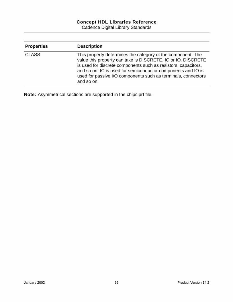
Concept HDL Libraries ReferenceCadence Digital Library Standards
Note: Asymmetrical sections are supported in the chips.prt file.
CLASS This property determines the category of the component. Thevalue this property can take is DISCRETE, IC or IO. DISCRETEis used for discrete components such as resistors, capacitors,and so on. IC is used for semiconductor components and IO isused for passive I/O components such as terminals, connectorsand so on.
Properties Description
January 2002 66 Product Version 14.2

Concept HDL Libraries Reference
4Simulation Views
Overview
In order to proceed with the simulation of parts, you need to create the simulation views. Thecreation of the views and their contents will depend on the following:
■ Whether Verilog or VHDL is used for simulation
■ Whether the simulation flow is based on map files or wrappers.
For map file based simulation using Verilog, you should create a directory and store theVerilog map files in this directory. Although the name of the directory is user-defined, it issuggested the directory be named vlog_map as that it is the convention followed for theCadence supplied libraries. The Verilog map files should be named verilog.map.
For wrapper based simulation using Verilog, create a directory and store the Verilog wrappersin this directory. The name of the directory is user-defined. However, it is suggested that thedirectory be named vlog_model to be consistent with the naming convention followed bythe Cadence supplied libraries. The Verilog wrapper file should be named verilog.v.
For map file based simulation using VHDL, you should create a directory store the VHDL mapfiles in this directory. The directory name is user-defined. The VHDL map files should benamed as vhdl.map.
For wrapper based simulation using VHDL, create a directory and store the VHDL wrappersin this directory. The VHDL wrapper file should be named vhdl.vhd.
Verilog Map File
The Verilog map file (verilog.map) specifies pin-to-port mapping information, and theparameters to be passed to the Verilog modules. Generally this file is only necessary forexternally defined libraries. This file can also be used for user-defined Verilog modules, butthis is not usually necessary.
January 2002 67 Product Version 14.2
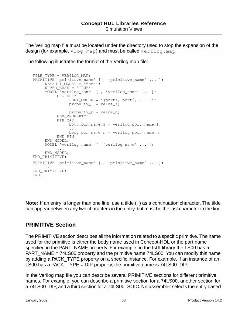
Concept HDL Libraries ReferenceSimulation Views
The Verilog map file must be located under the directory used to stop the expansion of thedesign (for example, vlog_map) and must be called verilog.map.
The following illustrates the format of the Verilog map file:
Note: If an entry is longer than one line, use a tilde (~) as a continuation character. The tildecan appear between any two characters in the entry, but must be the last character in the line.
PRIMITIVE Section
The PRIMITIVE section describes all the information related to a specific primitive. The nameused for the primitive is either the body name used in Concept-HDL or the part namespecified in the PART_NAME property. For example, in the lsttl library the LS00 has aPART_NAME = 74LS00 property and the primitive name 74LS00. You can modify this nameby adding a PACK_TYPE property on a specific instance. For example, if an instance of anLS00 has a PACK_TYPE = DIP property, the primitive name is 74LS00_DIP.
In the Verilog map file you can describe several PRIMITIVE sections for different primitivenames. For example, you can describe a primitive section for a 74LS00, another section fora 74LS00_DIP, and a third section for a 74LS00_SOIC. Netassembler selects the entry based
FILE_TYPE = VERILOG_MAP;PRIMITIVE ’primitive_name’ [ , ’primitive_name’ ... ];
DEFAULT_MODEL = ’name’;UPPER_CASE = ’TRUE’;MODEL ’verilog_name’ [ , ’verilog_name’ ... ];
PROPERTYPORT_ORDER = ’(port1, port2, ... )’;property_1 = value_1;...property_n = value_n;
END_PROPERTY;PIN_MAP
body_pin_name_1 = verilog_port_name_1;...body_pin_name_n = verilog_port_name_n;
END_PIN;END_MODEL;MODEL ’verilog_name’ [, ’verilog_name’ ... ];
...END_MODEL;
END_PRIMITIVE;
PRIMITIVE ’primitive_name’ [ , ’primitive_name’ ... ];...
END_PRIMITIVE;END.
January 2002 68 Product Version 14.2

Concept HDL Libraries ReferenceSimulation Views
on the primitive name for a specific instance. If there is no description for a primitive nameobtained with the PACK_TYPE property, Netassembler looks for an entry without thePACK_TYPE suffix.
For example, if there is no entry for a primitive called 74LS00_LCC, Netassembler looks fora 74LS00 entry; if not found, Netassembler generates an error. In most cases, thismechanism lets you describe only one primitive section as long as mapping information isindependent of the PACK_TYPE.
Two special entries can be defined in the PRIMITIVE section:
■ The DEFAULT_MODEL property is used to specify the default name of the Verilogmodel.
This default name is used by Netassembler as a default when no VERILOG_MODELproperty has been used on an instance.
■ The UPPER_CASE property is used to specify that a Verilog module name needs to bemade uppercase in the output netlist.
By default, all module names are lowercase unless changed by an UPPER_CASE=’TRUE’ property.
The following is an example of the PRIMITIVE section for an LS00:
The output in the netlist is the following:
SN74LS00I1P(net1, net2, net3);
MODEL Section
The MODEL section contains all information specific to one or several Verilog modules. Youcan specify several MODEL sections inside one PRIMITIVE section if you have severalVerilog modules available from a library that need different mapping information. At least oneMODEL section must be described in the PRIMITIVE section.
FILE_TYPE = VERILOG_MAP;PRIMITIVE ’74LS00’ , ’74LS00_DIP’;
DEFAULT_MODEL = ’SN74LS00’;UPPER_CASE = ’TRUE’;...
END_PRIMITIVE;END.
January 2002 69 Product Version 14.2

Concept HDL Libraries ReferenceSimulation Views
The following is an example of MODEL section for an LS00:
PROPERTY Section
The PROPERTY section inside the MODEL section specifies local properties that apply toonly one specific Verilog module. The PROPERTY section is optional. You can add as manyproperties as you want. Netassembler use the properties described in this section to specifywhich body properties to look for. For example, if a COMPONENT property is defined in theproperty section, Netassembler searches for the property on all instances of this part in thedesign. If found, Netassembler outputs the property as a parameter for the module usingdefparam in the Verilog netlist.
Two important properties are usually defined in this section:
■ The VERILOG_NAME property specifies the actual name of the Verilog model.
Internally, all names for modules are lowercase.
If the module you are using is either uppercase or contains a mixture of lowercase anduppercase characters, use the VERILOG_NAME property to specify the final name thatwill be output in the netlist.
■ The PORT_ORDER property specifies the order of the Verilog model ports.
This information is useful for the connection by position mode when no chips.prt file(with PIN_PROPERTY) has been defined for this module.
FILE_TYPE = VERILOG_MAP;PRIMITIVE ’74LS00’;
....MODEL ’SN74LS00’, ’SIG74LS00’ ;
...END_MODEL
END_PRIMITIVE;...END.
January 2002 70 Product Version 14.2
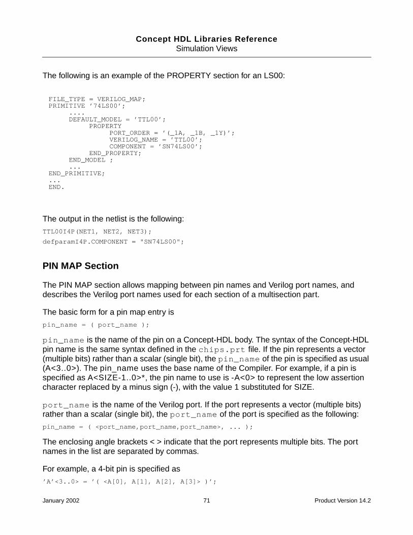
Concept HDL Libraries ReferenceSimulation Views
The following is an example of the PROPERTY section for an LS00:
The output in the netlist is the following:
TTL00I4P(NET1, NET2, NET3);
defparamI4P.COMPONENT = "SN74LS00";
PIN MAP Section
The PIN MAP section allows mapping between pin names and Verilog port names, anddescribes the Verilog port names used for each section of a multisection part.
The basic form for a pin map entry is
pin_name = ( port_name );
pin_name is the name of the pin on a Concept-HDL body. The syntax of the Concept-HDLpin name is the same syntax defined in the chips.prt file. If the pin represents a vector(multiple bits) rather than a scalar (single bit), the pin_name of the pin is specified as usual(A<3..0>). The pin_name uses the base name of the Compiler. For example, if a pin isspecified as A<SIZE-1..0>*, the pin name to use is -A<0> to represent the low assertioncharacter replaced by a minus sign (-), with the value 1 substituted for SIZE.
port_name is the name of the Verilog port. If the port represents a vector (multiple bits)rather than a scalar (single bit), the port_name of the port is specified as the following:
pin_name = ( <port_name,port_name,port_name>, ... );
The enclosing angle brackets < > indicate that the port represents multiple bits. The portnames in the list are separated by commas.
For example, a 4-bit pin is specified as
’A’<3..0> = ’( <A[0], A[1], A[2], A[3]> )’;
FILE_TYPE = VERILOG_MAP;PRIMITIVE ’74LS00’;
....DEFAULT_MODEL = ’TTL00’;
PROPERTYPORT_ORDER = ’(_1A, _1B, _1Y)’;VERILOG_NAME = ’TTL00’;COMPONENT = ’SN74LS00’;
END_PROPERTY;END_MODEL ;...
END_PRIMITIVE;...END.
January 2002 71 Product Version 14.2
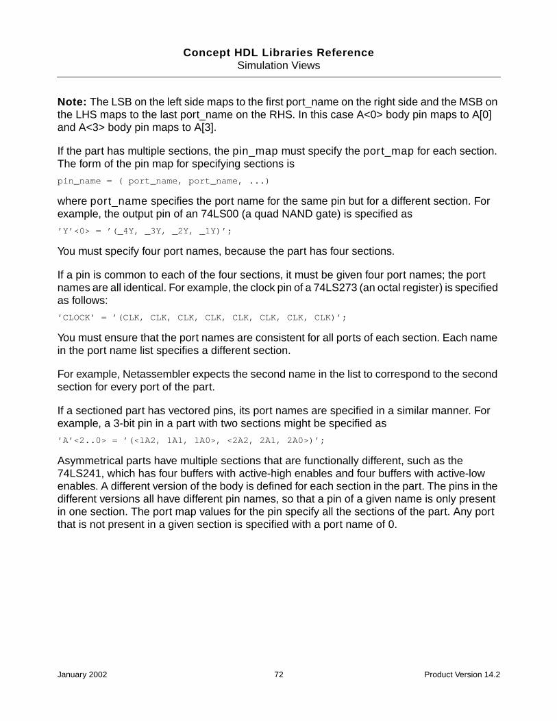
Concept HDL Libraries ReferenceSimulation Views
Note: The LSB on the left side maps to the first port_name on the right side and the MSB onthe LHS maps to the last port_name on the RHS. In this case A<0> body pin maps to A[0]and A<3> body pin maps to A[3].
If the part has multiple sections, the pin_map must specify the port_map for each section.The form of the pin map for specifying sections is
pin_name = ( port_name, port_name, ...)
where port_name specifies the port name for the same pin but for a different section. Forexample, the output pin of an 74LS00 (a quad NAND gate) is specified as
’Y’<0> = ’(_4Y, _3Y, _2Y, _1Y)’;
You must specify four port names, because the part has four sections.
If a pin is common to each of the four sections, it must be given four port names; the portnames are all identical. For example, the clock pin of a 74LS273 (an octal register) is specifiedas follows:
’CLOCK’ = ’(CLK, CLK, CLK, CLK, CLK, CLK, CLK, CLK)’;
You must ensure that the port names are consistent for all ports of each section. Each namein the port name list specifies a different section.
For example, Netassembler expects the second name in the list to correspond to the secondsection for every port of the part.
If a sectioned part has vectored pins, its port names are specified in a similar manner. Forexample, a 3-bit pin in a part with two sections might be specified as
’A’<2..0> = ’(<1A2, 1A1, 1A0>, <2A2, 2A1, 2A0>)’;
Asymmetrical parts have multiple sections that are functionally different, such as the74LS241, which has four buffers with active-high enables and four buffers with active-lowenables. A different version of the body is defined for each section in the part. The pins in thedifferent versions all have different pin names, so that a pin of a given name is only presentin one section. The port map values for the pin specify all the sections of the part. Any portthat is not present in a given section is specified with a port name of 0.
January 2002 72 Product Version 14.2

Concept HDL Libraries ReferenceSimulation Views
For example, the pin map section for an 74LS241 is the following:
The syntax for port mapping also allows for a more compact syntax. In addition to theprevious notation, the following features are also supported:
■ Subranges
Port map (Y4, Y3, Y2, Y1) is equivalent to (Y4..Y1)
■ Repeat sections
Port map (OE, OE, OE, OE) is equivalent to (OE * 4)
■ Vectored pins
Port map (<Y2..Y0> * 2) is equivalent to (<Y2, Y1, Y0>, <Y2, Y1, Y0>)
For example, the previously described 74LS241 can be described using the followingcompact syntax:
Note: Pin names in the Concept-HDL are case insensitive, but port names in Verilog arecase sensitive. Whatever is defined for the port name in the PIN_MAP section is used directlyin the output file.
PIN_MAP;’Y1’<0> = ’(_1Y4, _1Y3, _1Y2, _1Y1, 0, 0, 0, 0 )’;’B’<0> = ’(_1A4, _1A3, _1A2, _1A1, 0, 0, 0, 0)’;’-OE1’ = ’(_1G_, _1G_, _1G_, _1G_, 0, 0, 0, 0)’;’Y0’<0> = ’(0, 0, 0, 0, _2Y4, _2Y3, _2Y2, _2Y1)’;’A’<0> = ’(0, 0, 0, 0, _2A4, _2A3, _2A2, _2A1)’;’OE0’ = ’(0, 0, 0, 0, _2G, _2G, _2G, _2G)’;
END_PIN;
PIN_MAP;’Y1’<0> = ’(_1Y4 .. _1Y1, 0 * 4)’;’B’<0> = ’(_1A4, .. _1A1, 0 * 4)’;’-OE1’ = ’(_1G_ * 4, 0 * 4)’;’Y0’<0> = ’(0 * 4, _2Y4 .. _2Y1)’;’A’<0> = ’(0 * 4, _2A4 .. _2A1)’;’OE0’ = ’(0 *4, _2G * 4)’;
END_PIN;
January 2002 73 Product Version 14.2
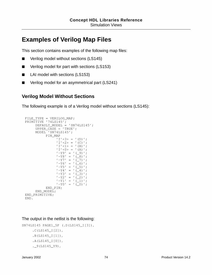
Concept HDL Libraries ReferenceSimulation Views
Examples of Verilog Map Files
This section contains examples of the following map files:
■ Verilog model without sections (LS145)
■ Verilog model for part with sections (LS153)
■ LAI model with sections (LS153)
■ Verilog model for an asymmetrical part (LS241)
Verilog Model Without Sections
The following example is of a Verilog model without sections (LS145):
The output in the netlist is the following:
SN74LS145 PAGE1_5P (.D(LS145_I[3]),
.C(LS145_I[2]),
.B(LS145_I[1]),
.A(LS145_I[0]),
._9(LS145_Y9),
FILE_TYPE = VERILOG_MAP;PRIMITIVE ’74LS145’;
DEFAULT_MODEL = ’SN74LS145’;UPPER_CASE = ’TRUE’;MODEL ’SN74LS145’;
PIN_MAP’I’<3> = ’(D)’;’I’<2> = ’(C)’;’I’<1> = ’(B)’;’I’<0> = ’(A)’;’-Y9’ = ’(_9)’;’-Y8’ = ’(_8)’;’-Y7’ = ’(_7)’;’-Y6’ = ’(_6)’;’-Y5’ = ’(_5)’;’-Y4’ = ’(_4)’;’-Y3’ = ’(_3)’;’-Y2’ = ’(_2)’;’-Y1’ = ’(_1)’;’-Y0’ = ’(_0)’;
END_PIN;END_MODEL;
END_PRIMITIVE;END.
January 2002 74 Product Version 14.2

Concept HDL Libraries ReferenceSimulation Views
._8(LS145_Y8),
.....
._0(LS145_Y0));
Verilog Model with Sections
The following example is a map file for a Verilog model for a part with sections (LS153):
The output in the netlist is the following:
SN74L3153I2P(._1Y(LS153_Y),
.B(LS153_S[1]),
.A(LS153_S[0]),
._1C3(LS153_I3),
._1C2(LS153_I2),
._1C1(LS153_I1),
._IC0(LS153_I0),
._1G_(LS153_E));
Note: To operate on a part that contains sections, Netassembler must have a chips.prtfile. The Cadence-provided standard parts library comes with a chips.prt file, so do notmodify it.
FILE_TYPE = VERILOG_MAP;PRIMITIVE ’74LS153’;
DEFAULT_MODEL = ’SN74LS153’;UPPER_CASE = ’TRUE’;MODEL ’SN74LS153’;
PIN_MAP’Y’<0> = ’(_2Y, _1Y)’;’S’<1> = ’(B, B)’;’S’<0> = ’(A, A)’;’I3’<0> = ’(_2C3, _1C3)’;’I2’<0> = ’(_2C2, _1C2)’;’I1’<0> = ’(_2C1, _1C1)’;’I0’<0> = ’(_2C0, _1C0)’;’-E’ = ’(_2G_, _1G_);
END_PIN;END_MODEL;
END_PRIMITIVE;END.
January 2002 75 Product Version 14.2
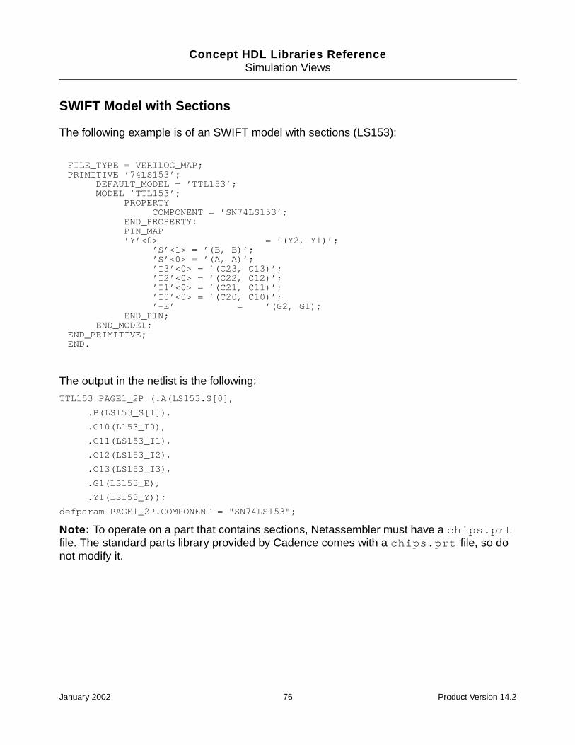
Concept HDL Libraries ReferenceSimulation Views
SWIFT Model with Sections
The following example is of an SWIFT model with sections (LS153):
The output in the netlist is the following:
TTL153 PAGE1_2P (.A(LS153.S[0],
.B(LS153_S[1]),
.C10(L153_I0),
.C11(LS153_I1),
.C12(LS153_I2),
.C13(LS153_I3),
.G1(LS153_E),
.Y1(LS153_Y));
defparam PAGE1_2P.COMPONENT = "SN74LS153";
Note: To operate on a part that contains sections, Netassembler must have a chips.prtfile. The standard parts library provided by Cadence comes with a chips.prt file, so donot modify it.
FILE_TYPE = VERILOG_MAP;PRIMITIVE ’74LS153’;
DEFAULT_MODEL = ’TTL153’;MODEL ’TTL153’;
PROPERTYCOMPONENT = ’SN74LS153’;
END_PROPERTY;PIN_MAP’Y’<0> = ’(Y2, Y1)’;
’S’<1> = ’(B, B)’;’S’<0> = ’(A, A)’;’I3’<0> = ’(C23, C13)’;’I2’<0> = ’(C22, C12)’;’I1’<0> = ’(C21, C11)’;’I0’<0> = ’(C20, C10)’;’-E’ = ’(G2, G1);
END_PIN;END_MODEL;
END_PRIMITIVE;END.
January 2002 76 Product Version 14.2

Concept HDL Libraries ReferenceSimulation Views
Verilog Model for Asymmetrical Parts
The following example is of a Verilog model for an asymmetrical part (LS241):
The output in the netlist is the following:
SN74LS241 PAGE1_1P (._2Y1(LS241_0),
._2G(LS241_E),
._2A1(LS241_I));
Note: To operate on an asymmetrical part, Netassembler must have a chips.prt file. Thestandard parts library provided by Cadence comes with a chips.prt file, so do not modifyit.
Verilog Wrappers
The Verilog wrapper (verilog.v) is a Verilog module declaration. The ports in the moduleshould match those declared in the Concept symbol. The module instantiates the originalVerilog model, with explicit port mapping to the ports declared in the Verilog model.
The following illustrates the structure of a Verilog wrapper file.
‘timescale 1ns/100ps
module als08 (a, b, y);
parameter size = 1;
input [size-1:0] a;
input [size-1:0] b;
FILE_TYPE = VERILOG_MAP;PRIMITIVE ’74LS241’;
DEFAULT_MODEL = ’SN74LS241’;UPPER_CASE = ’TRUE’;MODEL ’SN74LS241’;
PIN_MAP’Y1’<0> = ’(_1Y4, _1Y3, _1Y2, _1Y1, 0, 0, 0, 0 )’;’B’<0> = ’(_1A4, _1A3, _1A2, _1A1, 0, 0, 0, 0)’;’-OE1’ = ’(_1G_, _1G_, _1G_, _1G_, 0, 0, 0, 0)’;’Y0’<0> = ’(0, 0, 0, 0, _2Y4, _2Y3, _2Y2, _2Y1)’;’A’<0> = ’(0, 0, 0, 0, _2A4, _2A3, _2A2, _2A1)’;’OE0’ = ’(0, 0, 0, 0, _2G, _2G, _2G, _2G)’;
END_PIN;END_MODEL;
END_PRIMITIVE;END.
January 2002 77 Product Version 14.2
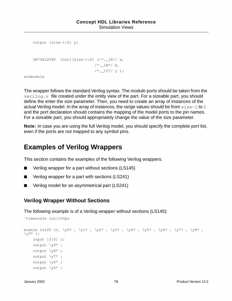
Concept HDL Libraries ReferenceSimulation Views
output [size-1:0] y;
SN74ALS08P inst1[size-1:0] (/*._1A*/ a,
/*._1B*/ b,
/*._1Y*/ y );
endmodule
The wrapper follows the standard Verilog syntax. The module ports should be taken from theverilog.v file created under the entity view of the part. For a sizeable part, you shoulddefine the enter the size parameter. Then, you need to create an array of instances of theactual Verilog model. In the array of instances, the range values should be from size-1 to 0and the port declaration should contains the mapping of the model ports to the pin names.For a sizeable part, you should appropriately change the value of the size parameter.
Note: In case you are using the full Verilog model, you should specify the complete port list,even if the ports are not mapped to any symbol pins.
Examples of Verilog Wrappers
This section contains the examples of the following Verilog wrappers:
■ Verilog wrapper for a part without sections (LS145)
■ Verilog wrapper for a part with sections (LS241)
■ Verilog model for an asymmetrical part (LS241)
Verilog Wrapper Without Sections
The following example is of a Verilog wrapper without sections (LS145):
‘timescale 1ns/100ps
module ls145 (i, \y0* , \y1* , \y2* , \y3* , \y4* , \y5* , \y6* , \y7* , \y8* ,\y9* );
input [3:0] i;
output \y9* ;
output \y8* ;
output \y7* ;
output \y6* ;
output \y5* ;
January 2002 78 Product Version 14.2
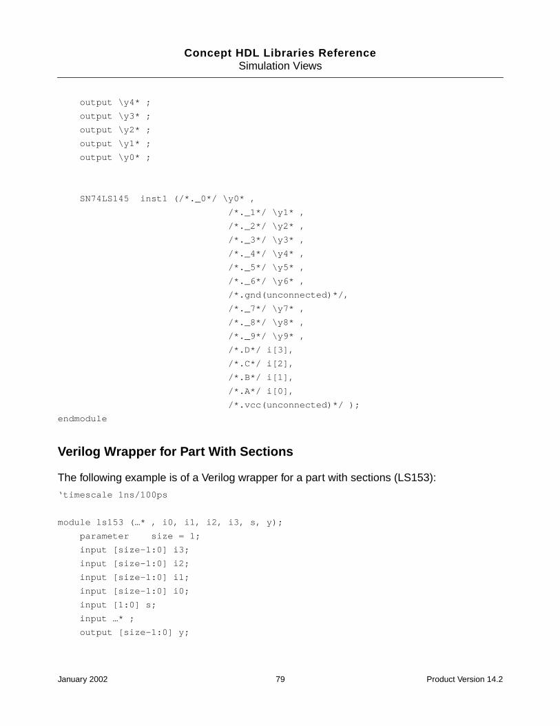
Concept HDL Libraries ReferenceSimulation Views
output \y4* ;
output \y3* ;
output \y2* ;
output \y1* ;
output \y0* ;
SN74LS145 inst1 (/*._0*/ \y0* ,
/*._1*/ \y1* ,
/*._2*/ \y2* ,
/*._3*/ \y3* ,
/*._4*/ \y4* ,
/*._5*/ \y5* ,
/*._6*/ \y6* ,
/*.gnd(unconnected)*/,
/*._7*/ \y7* ,
/*._8*/ \y8* ,
/*._9*/ \y9* ,
/*.D*/ i[3],
/*.C*/ i[2],
/*.B*/ i[1],
/*.A*/ i[0],
/*.vcc(unconnected)*/ );
endmodule
Verilog Wrapper for Part With Sections
The following example is of a Verilog wrapper for a part with sections (LS153):
‘timescale 1ns/100ps
module ls153 (…* , i0, i1, i2, i3, s, y);
parameter size = 1;
input [size-1:0] i3;
input [size-1:0] i2;
input [size-1:0] i1;
input [size-1:0] i0;
input [1:0] s;
input …* ;
output [size-1:0] y;
January 2002 79 Product Version 14.2
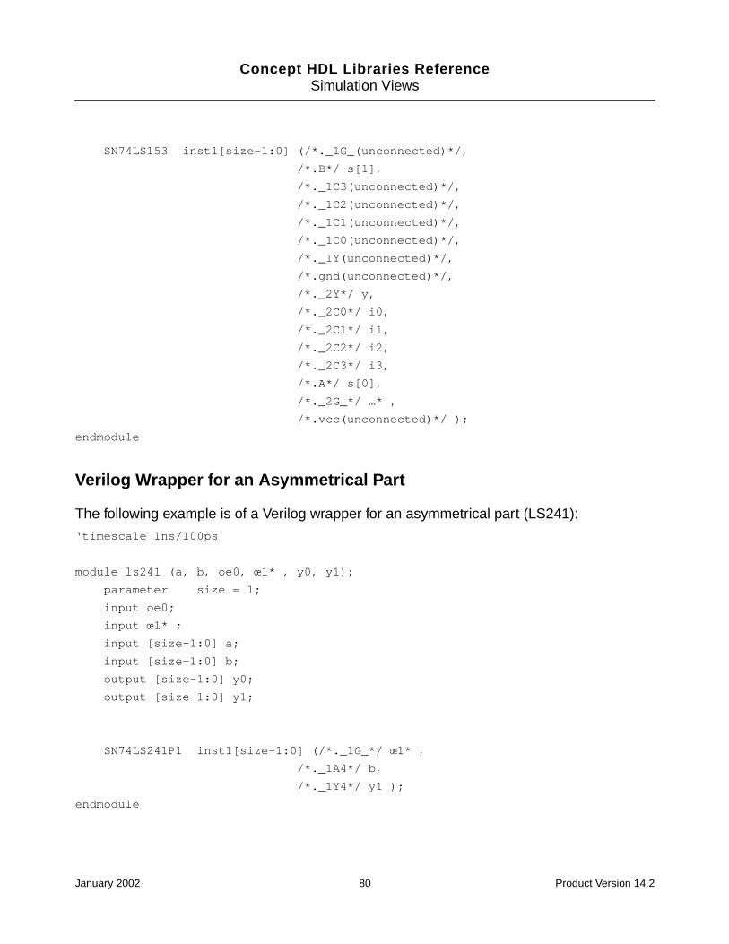
Concept HDL Libraries ReferenceSimulation Views
SN74LS153 inst1[size-1:0] (/*._1G_(unconnected)*/,
/*.B*/ s[1],
/*._1C3(unconnected)*/,
/*._1C2(unconnected)*/,
/*._1C1(unconnected)*/,
/*._1C0(unconnected)*/,
/*._1Y(unconnected)*/,
/*.gnd(unconnected)*/,
/*._2Y*/ y,
/*._2C0*/ i0,
/*._2C1*/ i1,
/*._2C2*/ i2,
/*._2C3*/ i3,
/*.A*/ s[0],
/*._2G_*/ …* ,
/*.vcc(unconnected)*/ );
endmodule
Verilog Wrapper for an Asymmetrical Part
The following example is of a Verilog wrapper for an asymmetrical part (LS241):
‘timescale 1ns/100ps
module ls241 (a, b, oe0, œ1* , y0, y1);
parameter size = 1;
input oe0;
input œ1* ;
input [size-1:0] a;
input [size-1:0] b;
output [size-1:0] y0;
output [size-1:0] y1;
SN74LS241P1 inst1[size-1:0] (/*._1G_*/ œ1* ,
/*._1A4*/ b,
/*._1Y4*/ y1 );
endmodule
January 2002 80 Product Version 14.2
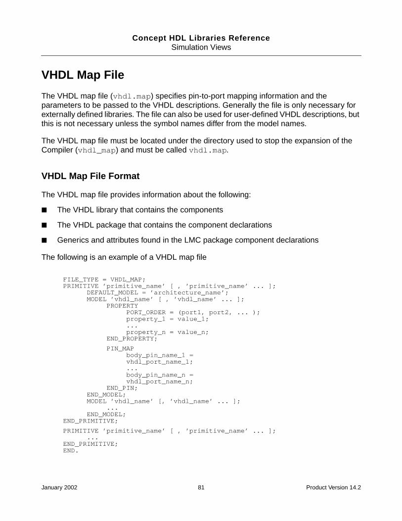
Concept HDL Libraries ReferenceSimulation Views
VHDL Map File
The VHDL map file (vhdl.map) specifies pin-to-port mapping information and theparameters to be passed to the VHDL descriptions. Generally the file is only necessary forexternally defined libraries. The file can also be used for user-defined VHDL descriptions, butthis is not necessary unless the symbol names differ from the model names.
The VHDL map file must be located under the directory used to stop the expansion of theCompiler (vhdl_map) and must be called vhdl.map.
VHDL Map File Format
The VHDL map file provides information about the following:
■ The VHDL library that contains the components
■ The VHDL package that contains the component declarations
■ Generics and attributes found in the LMC package component declarations
The following is an example of a VHDL map file
FILE_TYPE = VHDL_MAP;PRIMITIVE ’primitive_name’ [ , ’primitive_name’ ... ];
DEFAULT_MODEL = ’architecture_name’;MODEL ’vhdl_name’ [ , ’vhdl_name’ ... ];
PROPERTYPORT_ORDER = (port1, port2, ... );property_1 = value_1;...property_n = value_n;
END_PROPERTY;
PIN_MAPbody_pin_name_1 =vhdl_port_name_1;...body_pin_name_n =vhdl_port_name_n;
END_PIN;END_MODEL;MODEL ’vhdl_name’ [, ’vhdl_name’ ... ];
...END_MODEL;
END_PRIMITIVE;
PRIMITIVE ’primitive_name’ [ , ’primitive_name’ ... ];...
END_PRIMITIVE;END.
January 2002 81 Product Version 14.2

Concept HDL Libraries ReferenceSimulation Views
PRIMITIVE Section
The PRIMITIVE section describes all the information related to a specific primitive. The nameused for the primitive is either the body name used in Concept-HDL or the part namespecified in the PART_NAME property. For example, in the lsttl library the LS00 has aPART_NAME = 74LS00 property and the primitive name 74LS00. You can modify this nameby adding a PACK_TYPE property on a specific instance. For example, if an instance of anLS00 has a PACK_TYPE = DIP property, the primitive name is 74LS00_DIP.
In the VHDL map file you can describe several PRIMITIVE sections for different primitivenames. For example, you can describe a primitive section for a 74LS00, another section fora 74LS00_DIP, and a third section for a 74LS00_SOIC. Netassembler selects the entry basedon the primitive name for a specific instance. If there is no description for a primitive nameobtained with the PACK_TYPE property, Netassembler looks for an entry without thePACK_TYPE suffix.
For example, if there is no entry for a primitive called 74LS00_LCC, Netassembler looks fora 74LS00 entry; if not found, Netassembler generates an error. In most cases, Netassemblerlets you describe only one primitive section if mapping information is independent of thePACK_TYPE.
You can define two special entries in the PRIMITIVE section:
■ Use the DEFAULT_MODEL property to specify the default name of the VHDL model.
This default name is used by Netassembler as a default when no VHDL_MODELproperty has been used on an instance.
■ Use the UPPER_CASE property to specify that a VHDL description name must be madeuppercase in the output netlist.
By default, all description names are lowercase unless changed by an UPPER_CASE =’TRUE’ property.
The following is an example of the PRIMITIVE section for an LS00:
FILE_TYPE = VHDL_MAP;PRIMITIVE ’74LS00’ , ’74LS00_DIP’;
DEFAULT_MODEL = ’SN74LS00’;UPPER_CASE = ’TRUE’;...
END_PRIMITIVE;END.
January 2002 82 Product Version 14.2
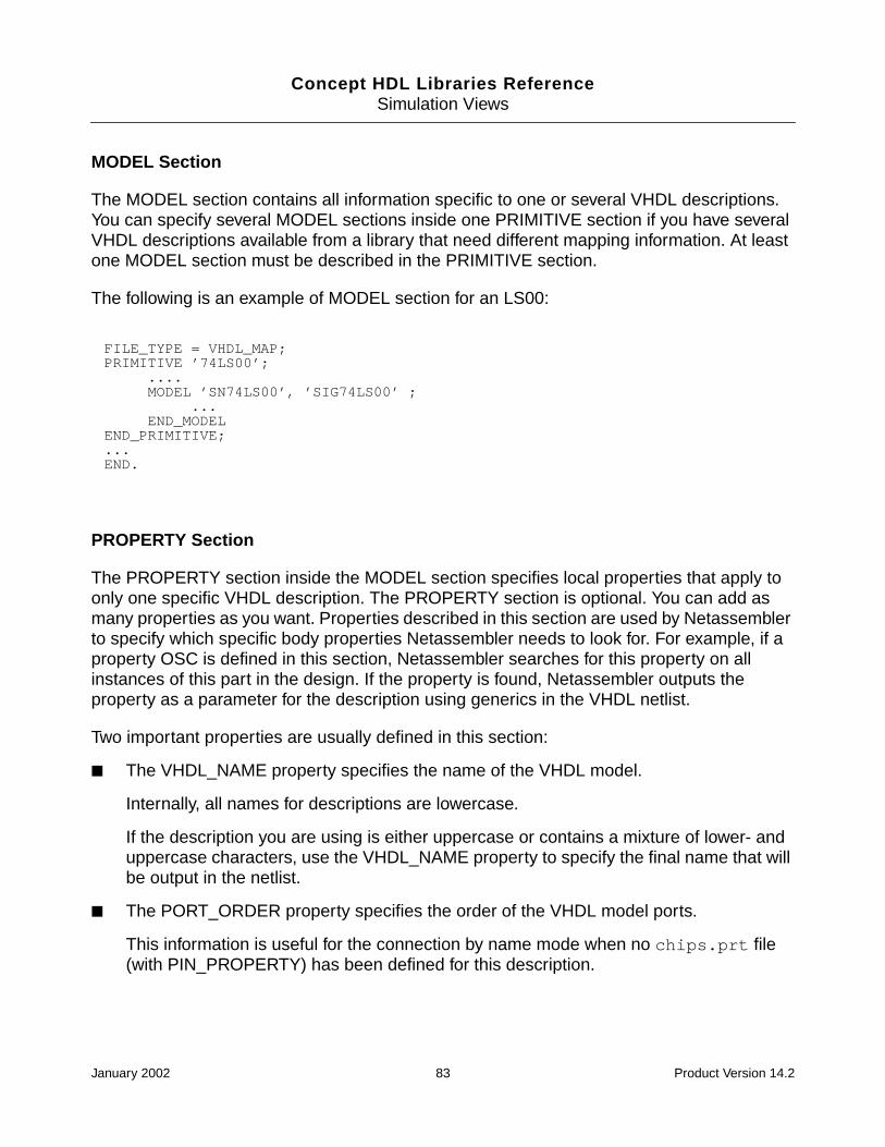
Concept HDL Libraries ReferenceSimulation Views
MODEL Section
The MODEL section contains all information specific to one or several VHDL descriptions.You can specify several MODEL sections inside one PRIMITIVE section if you have severalVHDL descriptions available from a library that need different mapping information. At leastone MODEL section must be described in the PRIMITIVE section.
The following is an example of MODEL section for an LS00:
PROPERTY Section
The PROPERTY section inside the MODEL section specifies local properties that apply toonly one specific VHDL description. The PROPERTY section is optional. You can add asmany properties as you want. Properties described in this section are used by Netassemblerto specify which specific body properties Netassembler needs to look for. For example, if aproperty OSC is defined in this section, Netassembler searches for this property on allinstances of this part in the design. If the property is found, Netassembler outputs theproperty as a parameter for the description using generics in the VHDL netlist.
Two important properties are usually defined in this section:
■ The VHDL_NAME property specifies the name of the VHDL model.
Internally, all names for descriptions are lowercase.
If the description you are using is either uppercase or contains a mixture of lower- anduppercase characters, use the VHDL_NAME property to specify the final name that willbe output in the netlist.
■ The PORT_ORDER property specifies the order of the VHDL model ports.
This information is useful for the connection by name mode when no chips.prt file(with PIN_PROPERTY) has been defined for this description.
FILE_TYPE = VHDL_MAP;PRIMITIVE ’74LS00’;
....MODEL ’SN74LS00’, ’SIG74LS00’ ;
...END_MODEL
END_PRIMITIVE;...END.
January 2002 83 Product Version 14.2

Concept HDL Libraries ReferenceSimulation Views
The following is an example of the PROPERTY section for an LS00:
PIN MAP Section
The PIN MAP section allows mapping between pin names and VHDL port names, anddescribes the VHDL port names used for each section of a part that has more than onesection.
The basic form for a pin map entry is
pin_name = “( port_name )’’<port_mode>’’<port_type>’’;
where port_mode and port_type are optional.
The pin_name is the name of the pin on a Concept-HDL body. If the pin represents a vector(multiple bits) rather than a scalar (single bit), the pin_name of the pin is specified as usual(A<3..0>). The pin_name uses the base name of the Compiler. For example, if a pin isspecified as A<SIZE-1..0>* the pin name to use is -A<0> to represent the low assertioncharacter replaced by a minus sign (-), with the value 1 substituted for SIZE.
The port_name is the name of the VHDL port. If the port represents a vector (multiple bits)rather than a scalar (single bit), specify the port name as follows:
The port_mode is one of the following:
inout
FILE_TYPE = VHDL_MAP;PRIMITIVE ’74LS00’;
....DEFAULT_MODEL = ’SN74LS00’;
PROPERTYPORT_ORDER = ’(A_1, B_1, Y_1)’;VHDL_NAME = ’SN74LS00’;
END_PROPERTY;END_MODEL...
END_PRIMITIVE;...END.
pin_name = ’’(<port_name,port_name,port_name>, ...)’’<port_mode>’’<port_type>’’;
January 2002 84 Product Version 14.2

Concept HDL Libraries ReferenceSimulation Views
inoutbuffer
The enclosing angle brackets < > indicate that the port represents multiple bits. The portnames in the list are separated by commas.
For example, a 4-bit pin is specified as
A<3..0> = “( <A3, A2, A1, A0> )“inout’’std_logic’’;
If the part has multiple sections, the pin_map must specify the port_map for each section.The form of the pin map for specifying sections is
pin_name = ’’( port_name, port_name, ...)
’’<port_mode>’’<port_type>’’;
where port_name specifies the port name for the same pin but for a different section. Forexample, the output pin of an 74LS00 (a quad NAND gate) is specified as
Y<0> = ’’(Y_4, Y_3, Y_2, Y_1)’’out’’std_ulogic’’;
There must be four port names specified because the part has four sections.
If a pin is common to each of the four sections, it must be given four port names; the portnames are all identical. For example, the clock pin of a 74LS273 (an octal register) is specifiedas follows:
CLOCK = (CLK, CLK, CLK, CLK, CLK, CLK, CLK, CLK);
You must ensure that the port names are consistent for all ports of each section. Each namein the port name list specifies a different section. Netassembler expects the second name inthe list, for example, to correspond to the second section for every port of the part.
If a sectioned part has vectored pins, its port names are specified in a similar manner. Forexample, a 3-bit pin in a part with two sections might be specified as
A<2..0> = (<A1_2, A1_1, A1_0>, <A2_2, A2_1, A2_0>);
Asymmetrical parts have multiple sections that are functionally different, such as the74LS241, which has four buffers with active-high enables and four buffers with active-lowenables. A different version of the body is defined for each section in the part. The pins in thedifferent versions all have different pin names, so that a pin of a given name is only presentin one section. The port map values for the pin specify all the sections of the part. Any portthat is not present in a given section is specified with a port name of 0.
For example, the pin map section for 74LS241 is the following:
January 2002 85 Product Version 14.2

Concept HDL Libraries ReferenceSimulation Views
PIN_MAP;’Y1’<0> = ’(Y1_4,Y1_3,Y1_2,Y1_1,open,open,open,open)’;’B’<0> = ’(A1_4,A1_3,A1_2,A1_1,open,open,open,open)’;’-OE1’ = ’(G1,G1,G1,G1,open,open,open,open)’;’Y0’<0> = ’(open,open,open,open,Y2_4,Y2_3,Y2_2,Y2_1)’;’A’<0> = ’(open,open,open,open,A2_4,A2_3,A2_2,A2_1)’;’OE0’ = ’(open,open,open,open,G2,G2,G2,G2)’;END_PIN;
The syntax for port mapping also allows for a more compact syntax. In addition to theprevious notation, the following features are also supported:
■ Subranges
Port map (Y4, Y3, Y2, Y1) is equivalent to (Y4..Y1)
■ Repeat sections
Port map (OE, OE, OE, OE) is equivalent to (OE * 4)
■ Vectored pins
Port map (<Y2..Y0> * 2) is equivalent to (<Y2, Y1, Y0>, <Y2, Y1, Y0>)
For example, the previously described 74LS241 can be described using the followingcompact syntax:
Note: Pin names in Concept-HDL are case-insensitive, but port names in VHDL are case-sensitive. Whatever is defined for the port name in the PIN_MAP section is used directly inthe output file.
Examples of VHDL Map Files
This section contains examples of the following map files:
■ VHDL model without sections (LS145)
PIN_MAP;’Y1’<0> = ’(Y1_4 .. Y1_1,open * 4)’;’B’<0> = ’(A1_4 .. A1_1,open * 4)’;’-OE1’ = ’(G1 * 4,open * 4)’;’Y0’<0> = ’(open * 4,Y2_4 .. Y2_1)’;’A’<0> = ’(open * 4,A2_4 .. A2_1)’;’OE0’ = ’(open * 4,G2 * 4)’;
END_PIN;
January 2002 86 Product Version 14.2

Concept HDL Libraries ReferenceSimulation Views
■ VHDL model for part with sections (LS153)
■ VHDL model for an asymmetrical part (LS241)
VHDL Model Without Sections
The following is an example of a VHDL model without sections (LS145):
FILE_TYPE = VHDL_MAP;PRIMITIVE ’74LS145’;
DEFAULT_MODEL = ’SN74LS145’;UPPER_CASE = ’TRUE’;MODEL ’SN74LS145’;
PIN_MAP’I’<3> = ’(C2_3, C1_3)’;’I’<2> = ’(C2_2, C1_2)’;’I’<1> = ’(C2_1, C1_1)’;’I’<0> = ’(C2_0, C1_0)’;’-Y9’ = ’(Y9)’;’-Y8’ = ’(Y8)’;’-Y6’ = ’(Y6)’;’-Y5’ = ’(Y5)’;’-Y4’ = ’(Y4)’;’-Y3’ = ’(Y3)’;’-Y2’ = ’(Y2)’;’-Y1’ = ’(Y1)’;’-Y0’ = ’(Y0)’;
END_PIN;END_MODEL;
END_PRIMITIVE;END.
January 2002 87 Product Version 14.2

Concept HDL Libraries ReferenceSimulation Views
VHDL Model with Sections
The following is an example of a map file for a VHDL model for a part with sections (LS153):
VHDL Model for Asymmetrical Parts
The following is an example of a VHDL model for an asymmetrical part (LS241):
FILE_TYPE = VHDL_MAP;PRIMITIVE ’74LS153’;
DEFAULT_MODEL = ’SN74LS153’;UPPER_CASE = ’TRUE’;MODEL ’SN74LS153’;
PIN_MAP’Y’<0> = ’(Y_2, Y_1)’;’S’<1> = ’(B, B)’;’S’<0> = ’(A, A)’;’I3’<0> = ’(C2_3, C1_3)’;’I2’<0> = ’(C2_2, C1_2)’;’I1’<0> = ’(C2_1, C1_1)’;’I0’<0> = ’(C2_0, C1_0)’;’-E’ = ’(G2, G1);
END_PIN;END_MODEL;
END_PRIMITIVE;END.
FILE_TYPE = VHDL_MAP;PRIMITIVE ’74LS241’;
DEFAULT_MODEL = ’SN74LS241’;UPPER_CASE = ’TRUE’;MODEL ’SN74LS241’;
PIN_MAP’Y1’<0> = ’(Y1_4,Y1_3,Y1_2, Y1_1,open,open,open,open)’;’B’<0> = ’(A1_4,A1_3,A1_2,A1_1,open,open,open,open)’;’-OE1’ = ’(G1,G1,G1,G1,open,open,open,open)’;’Y0’<0> = ’(open,open,open,open,Y2_4,Y2_3,Y2_2,Y2_1)’;’A’<0> = ’(open,open,open,open,A2_4,A2_3,A2_2,A1)’;’OE0’ = ’(open,open,open,open,G_2,G_2,G_2,G_2)’;
END_PIN;END_MODEL;
END_PRIMITIVE;END.
January 2002 88 Product Version 14.2
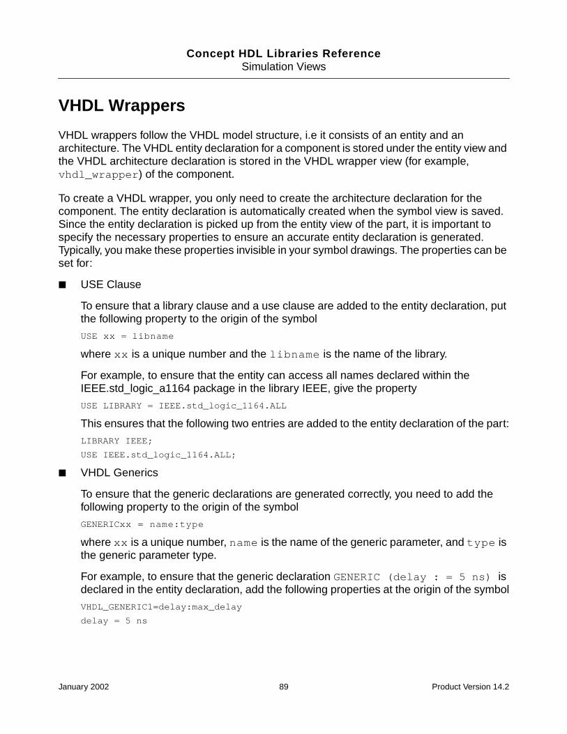
Concept HDL Libraries ReferenceSimulation Views
VHDL Wrappers
VHDL wrappers follow the VHDL model structure, i.e it consists of an entity and anarchitecture. The VHDL entity declaration for a component is stored under the entity view andthe VHDL architecture declaration is stored in the VHDL wrapper view (for example,vhdl_wrapper) of the component.
To create a VHDL wrapper, you only need to create the architecture declaration for thecomponent. The entity declaration is automatically created when the symbol view is saved.Since the entity declaration is picked up from the entity view of the part, it is important tospecify the necessary properties to ensure an accurate entity declaration is generated.Typically, you make these properties invisible in your symbol drawings. The properties can beset for:
■ USE Clause
To ensure that a library clause and a use clause are added to the entity declaration, putthe following property to the origin of the symbol
USE xx = libname
where xx is a unique number and the libname is the name of the library.
For example, to ensure that the entity can access all names declared within theIEEE.std_logic_a1164 package in the library IEEE, give the property
USE LIBRARY = IEEE.std_logic_1164.ALL
This ensures that the following two entries are added to the entity declaration of the part:
LIBRARY IEEE;
USE IEEE.std_logic_1164.ALL;
■ VHDL Generics
To ensure that the generic declarations are generated correctly, you need to add thefollowing property to the origin of the symbol
GENERICxx = name:type
where xx is a unique number, name is the name of the generic parameter, and type isthe generic parameter type.
For example, to ensure that the generic declaration GENERIC (delay : = 5 ns) isdeclared in the entity declaration, add the following properties at the origin of the symbol
VHDL_GENERIC1=delay:max_delay
delay = 5 ns
January 2002 89 Product Version 14.2

Concept HDL Libraries ReferenceSimulation Views
After the entity declaration has been taken care of, you need to create the architecturedeclaration. Following is the general syntax for writing the architecture:
architecture <wrapper_view_name> of <part_name> is
component <VHDL_component>
generic(
generic declarations
)
port (
port declarations
);
end component;
begin
L0: For I in 0 to SIZE-1 generate -- Required only for sizeable parts
L1:block
for inst1: <VHDL_component> use entity lib.vhdl_model(vhdl_arch); -- bindingstatement
begin
inst1: <VHDL_component>
generic map(
generic maps
)
port map (
port maps
)
end block;
end generate L0;
end vhdl_wrapper;
Note: In case the part is not sizeable, you do not need to put the generate statement.
Mapping Scenarios
Following is the description of the various mapping scenarios possible while creating VHDLwrappers.
Mapping Scalar Pins With Scalar Ports
Following is the description of the method by which scalar pins are to be mapped to the scalarports.
January 2002 90 Product Version 14.2
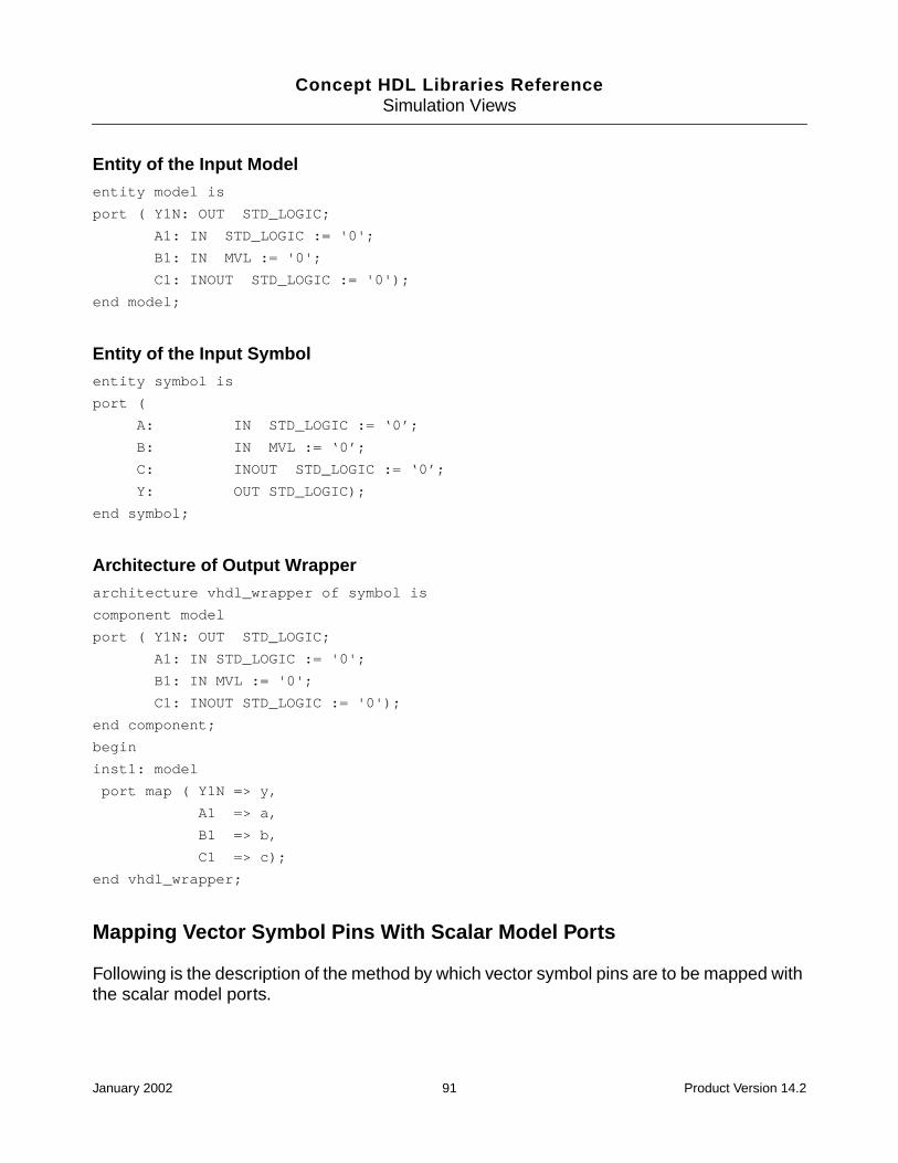
Concept HDL Libraries ReferenceSimulation Views
Entity of the Input Modelentity model is
port ( Y1N: OUT STD_LOGIC;
A1: IN STD_LOGIC := '0';
B1: IN MVL := '0';
C1: INOUT STD_LOGIC := '0');
end model;
Entity of the Input Symbolentity symbol is
port (
A: IN STD_LOGIC := ‘0’;
B: IN MVL := ‘0’;
C: INOUT STD_LOGIC := ‘0’;
Y: OUT STD_LOGIC);
end symbol;
Architecture of Output Wrapperarchitecture vhdl_wrapper of symbol is
component model
port ( Y1N: OUT STD_LOGIC;
A1: IN STD_LOGIC := '0';
B1: IN MVL := '0';
C1: INOUT STD_LOGIC := '0');
end component;
begin
inst1: model
port map ( Y1N => y,
A1 => a,
B1 => b,
C1 => c);
end vhdl_wrapper;
Mapping Vector Symbol Pins With Scalar Model Ports
Following is the description of the method by which vector symbol pins are to be mapped withthe scalar model ports.
January 2002 91 Product Version 14.2

Concept HDL Libraries ReferenceSimulation Views
Entity of the Input Modelentity model is
port (inport1: in std_logic;
inport2: in std_logic;
inport3: in std_logic;
outport: out std_logic);
end model;
Entity of the Input Symbolentity symbol is
port (pin_vector: in std_logic_vector (2 downto 0);
pin_sclar: out std_logic);
end symbol;
Architecture of the Output Wrapperarchitecture vhdl_wrapper of symbol is
component model
port (inport0: in std_logic;
inport1: in std_logic;
inport2: in std_logic;
outport: out std_logic);
end component;
begin
inst1: model
port map(
inport0 => pin_vector(0),
inport1 => pin_vector(1),
inport2 => pin_vector(2),
outport => pin_scalar);
end vhdl_wrapper;
Note: You should follow similarly with escaped port names in either the model or the symbol.
Mapping Scalar Pins With Vector Ports
Following is the description of the method by which you should map scalar pins with vectorports.
January 2002 92 Product Version 14.2
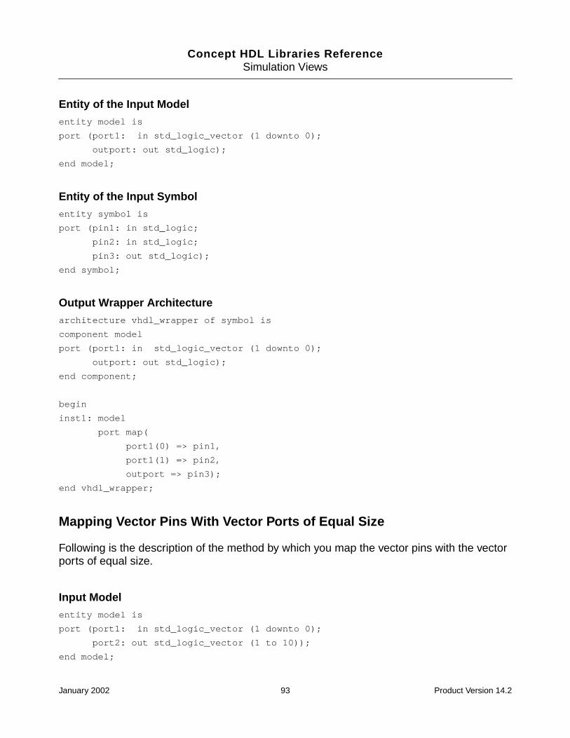
Concept HDL Libraries ReferenceSimulation Views
Entity of the Input Modelentity model is
port (port1: in std_logic_vector (1 downto 0);
outport: out std_logic);
end model;
Entity of the Input Symbolentity symbol is
port (pin1: in std_logic;
pin2: in std_logic;
pin3: out std_logic);
end symbol;
Output Wrapper Architecturearchitecture vhdl_wrapper of symbol is
component model
port (port1: in std_logic_vector (1 downto 0);
outport: out std_logic);
end component;
begin
inst1: model
port map(
port1(0) => pin1,
port1(1) => pin2,
outport => pin3);
end vhdl_wrapper;
Mapping Vector Pins With Vector Ports of Equal Size
Following is the description of the method by which you map the vector pins with the vectorports of equal size.
Input Modelentity model is
port (port1: in std_logic_vector (1 downto 0);
port2: out std_logic_vector (1 to 10));
end model;
January 2002 93 Product Version 14.2

Concept HDL Libraries ReferenceSimulation Views
Input Symbolentity symbol is
port (pin1: in std_logic_vector (1 downto 0);
pin2: out std_logic_vector (1 to 10));
end symbol;
Output Wrapper
■ When the LSB and the MSB are to be mapped in the same order.architecture vhdl_wrapper of symbol is
component model
port (port1: in std_logic_vector (1 downto 0);
port2: out std_logic_vector (1 to 10));
end component;
begin
inst1: model
port map(
port1 => pin1,
port2 => pin2);
end vhdl_wrapper;
■ When the LSB and the MSB are bit reversedarchitecture vhdl_wrapper of symbol is
component model
port (port1: in std_logic_vector (1 downto 0);
port2: out std_logic_vector (1 to 10));
end component;
begin
inst1: model
port map(
port1(0) => pin1(1),
port1(1) => pin1(0)
port2 => pin2);
end vhdl_wrapper;
Mapping Vector Pins With a Combination of Vector Ports:
Following is the description of how to map vector pins with a combination of vector ports.
January 2002 94 Product Version 14.2
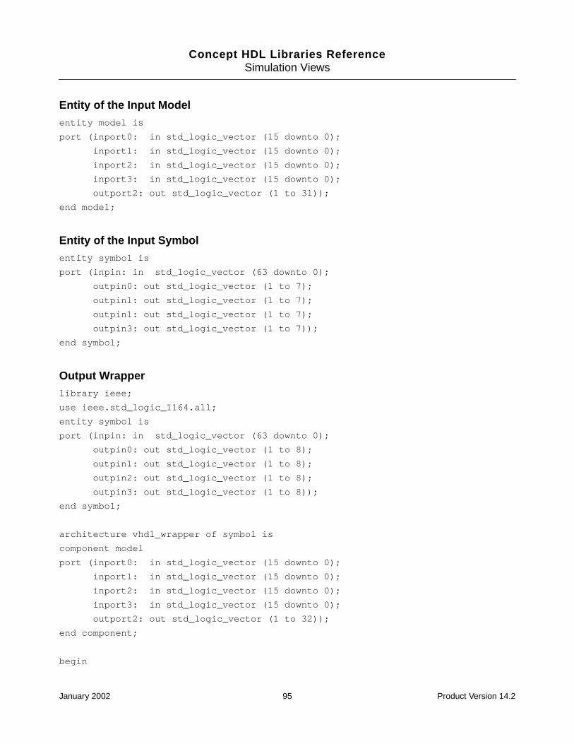
Concept HDL Libraries ReferenceSimulation Views
Entity of the Input Modelentity model is
port (inport0: in std_logic_vector (15 downto 0);
inport1: in std_logic_vector (15 downto 0);
inport2: in std_logic_vector (15 downto 0);
inport3: in std_logic_vector (15 downto 0);
outport2: out std_logic_vector (1 to 31));
end model;
Entity of the Input Symbolentity symbol is
port (inpin: in std_logic_vector (63 downto 0);
outpin0: out std_logic_vector (1 to 7);
outpin1: out std_logic_vector (1 to 7);
outpin1: out std_logic_vector (1 to 7);
outpin3: out std_logic_vector (1 to 7));
end symbol;
Output Wrapperlibrary ieee;
use ieee.std_logic_1164.all;
entity symbol is
port (inpin: in std_logic_vector (63 downto 0);
outpin0: out std_logic_vector (1 to 8);
outpin1: out std_logic_vector (1 to 8);
outpin2: out std_logic_vector (1 to 8);
outpin3: out std_logic_vector (1 to 8));
end symbol;
architecture vhdl_wrapper of symbol is
component model
port (inport0: in std_logic_vector (15 downto 0);
inport1: in std_logic_vector (15 downto 0);
inport2: in std_logic_vector (15 downto 0);
inport3: in std_logic_vector (15 downto 0);
outport2: out std_logic_vector (1 to 32));
end component;
begin
January 2002 95 Product Version 14.2
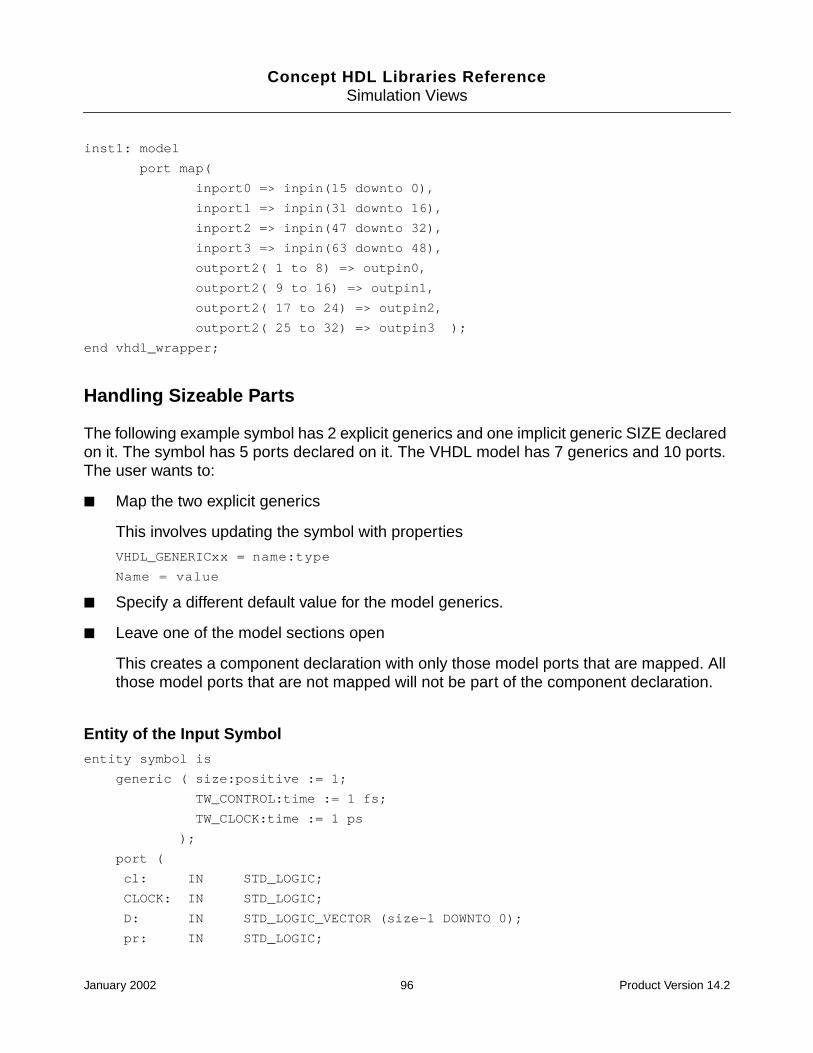
Concept HDL Libraries ReferenceSimulation Views
inst1: model
port map(
inport0 => inpin(15 downto 0),
inport1 => inpin(31 downto 16),
inport2 => inpin(47 downto 32),
inport3 => inpin(63 downto 48),
outport2( 1 to 8) => outpin0,
outport2( 9 to 16) => outpin1,
outport2( 17 to 24) => outpin2,
outport2( 25 to 32) => outpin3 );
end vhdl_wrapper;
Handling Sizeable Parts
The following example symbol has 2 explicit generics and one implicit generic SIZE declaredon it. The symbol has 5 ports declared on it. The VHDL model has 7 generics and 10 ports.The user wants to:
■ Map the two explicit generics
This involves updating the symbol with properties
VHDL_GENERICxx = name:type
Name = value
■ Specify a different default value for the model generics.
■ Leave one of the model sections open
This creates a component declaration with only those model ports that are mapped. Allthose model ports that are not mapped will not be part of the component declaration.
Entity of the Input Symbolentity symbol is
generic ( size:positive := 1;
TW_CONTROL:time := 1 fs;
TW_CLOCK:time := 1 ps
);
port (
cl: IN STD_LOGIC;
CLOCK: IN STD_LOGIC;
D: IN STD_LOGIC_VECTOR (size-1 DOWNTO 0);
pr: IN STD_LOGIC;
January 2002 96 Product Version 14.2

Concept HDL Libraries ReferenceSimulation Views
Q: OUT STD_LOGIC_VECTOR (size-1 DOWNTO 0);
qb: OUT STD_LOGIC_VECTOR (size-1 DOWNTO 0));
end symbol;
Entity of the Input modelentity model is
generic (
tw_cntl : time := 5 ns;
tw_clk : time := 5 ns;
tsu_cntl : time := 0 ns;
ts_data : time := 3 ns;
th_data : time := 0.5 ns;
tp_cntl_max : time := 10.5 ns;
tp_clk_max : time := 10.5 ns );
port (
pre1_n : in std_logic := 'U';
clr1_n : in std_logic := 'U';
d1 : in std_logic := 'U';
clk1 : in std_logic := 'U';
q1 : out std_logic;
qb1 : out std_logic;
pre2_n : in std_logic := 'U';
clr2_n : in std_logic := 'U';
d2 : in std_logic := 'U';
clk2 : in std_logic := 'U';
q2 : out std_logic;
qb2 : out std_logic
);
end model;
Output Wrapper
In this example, the symbol is sizeable and the model is a full model with two sections. So,one of the two model sections must be left unconnected. Suppose you specify the mappingonly for the second section of the model, the component declaration as shown below, mustnot have the ports:
■ pre1_n, clr1_n, d1, clk1, q1 and qb1
January 2002 97 Product Version 14.2

Concept HDL Libraries ReferenceSimulation Views
architecture vhdl_wrapper of symbol is
component model
generic(
TW_CNTL:TIME := 5 NS;
TW_CLK:TIME := 5 NS;
TSU_CNTL:TIME := 0 NS;
TS_DATA:TIME := 3 NS;
TH_DATA:TIME := 0.5 NS;
TP_CNTL_MAX:TIME := 10.5 NS;
TP_CLK_MAX:TIME := 10.5 NS);
port(
PRE2_N: in STD_LOGIC := 'U';
CLR2_N: in STD_LOGIC := 'U';
D2: in STD_LOGIC := 'U';
CLK2: in STD_LOGIC := 'U';
Q2: out STD_LOGIC;
QB2: out STD_LOGIC
);
end component;
begin
L0: For I in 0 to SIZE-1 generate
l1: block
for l2: symbol use entity lib.model(vhdl_arch);
begin l2: model
generic_map (
TW_CNTL => TW_CONTROL ;
TW_CLK => TW_CLOCK;
TSU_CNTL => 10 NS;
TS_DATA => 3.5 NS;
TP_CLK_MAX => 11.25 NS);
port map (
PRE2_N => pr,
CLR2_N => cl,
D2 => D(i),
January 2002 98 Product Version 14.2

Concept HDL Libraries ReferenceSimulation Views
CLK2 => CLOCK,
Q2 => Q(i),
QB2 => qb(i));
end block;
end generate L0;
end vhdl_wrapper;
Case Sensitivity
VHDL is case insensitive in the normal namespace. However, it is case sensitive when thenames are in the escaped namespace. Escaped names start with a \ and are delimited by \.
For example: 74ac74 in Concept-HDL namespace is \74ac74\ in VHDL namespace.
Here are more examples of case-sensitive names:
Q2 => \QB*\(i),
QB2 => \qb*\(i));
Please note that QB* and qb* are different identifiers here.
January 2002 99 Product Version 14.2

Concept HDL Libraries ReferenceSimulation Views
January 2002 100 Product Version 14.2
Concept HDL Libraries Reference
5Testing Libraries
Library Utilities
After you create libraries and parts, you should validate them before releasing them to thedesigners. The following utilities are available for validation:
■ hlibgenxml
■ hlibftb
■ hlibsim
■ hlibchk
These utilities are located at:
your_install_dir/tools/libutil
You must set the path to your_install_dir/tools/libutil before running theseutilities.
hlibgenxmpl
Overview
The hlibgenxmpl utility instantiates cell(s) of a Concept-HDL library on a design sheet andwrites it to disk. hlibgenxmpl creates one design sheet for each package type. All the cellssupporting a particular package type are instantiated on the sheet of that package type. Foreach created design sheet, hlibgenxmpl makes a .cpm file, which it saves in the workingdirectory.
January 2002 101 Product Version 14.2
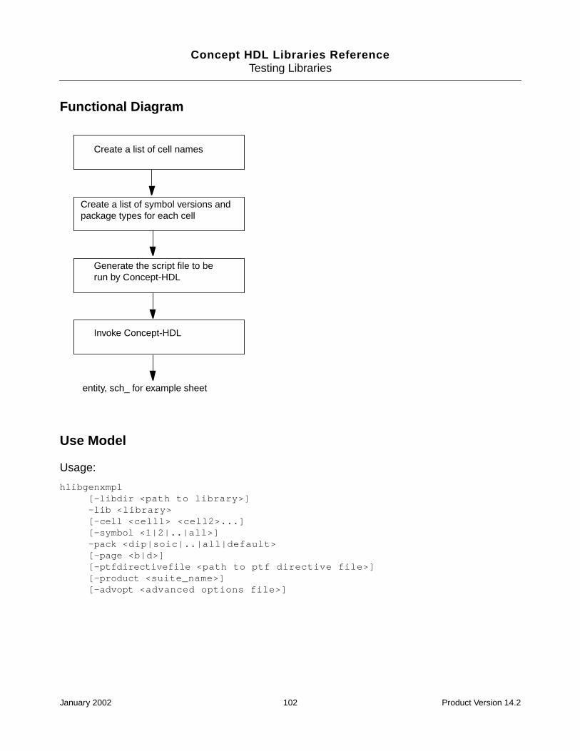
Concept HDL Libraries ReferenceTesting Libraries
Functional Diagram
Use Model
Usage:
hlibgenxmpl[-libdir <path to library>]-lib <library>[-cell <cell1> <cell2>...][-symbol <1|2|..|all>]-pack <dip|soic|..|all|default>[-page <b|d>][-ptfdirectivefile <path to ptf directive file>][-product <suite_name>][-advopt <advanced options file>]
Create a list of cell names
Create a list of symbol versions andpackage types for each cell
Generate the script file to berun by Concept-HDL
Invoke Concept-HDL
entity, sch_ for example sheet
January 2002 102 Product Version 14.2

Concept HDL Libraries ReferenceTesting Libraries
Usage Explanation
-libdir <path tolibrary>
(Optional) Specify the path to the library. If you do notspecify the path, hlibgenxmpl looks for the cds.lib file inthe working directory. If there is no cds.lib file in theworking directory, hlibgenxmpl creates a cds.lib file.
Note: If a cds.lib file exists in the working directory, thenthe -libdir option is ignored.
-lib <library> Specify the name of the Concept-HDL library to be tested.The location of the Concept-HDL library is passed eitherthrough the cds.lib file mapping or through the -libdiroption.
-cell <cell1> <cell2>..
(Optional) Specify the cells that need to be selectivelytested. If the selective cells are not specified,hlibgenxmpl tests all the cells in the specified library.
Note: The -cell option can be used only if the -liboption has been used.
-symbol <1|2|..|all> (Optional) Specify the symbol versions to be tested.Specify “1” to test only sym_1. Specify “2” to test onlysym_2. Specify “all” to test all symbols in the cell.If the-symbol option is not used, hlibgenxmpl tests all thesymbols in the specified cell(s).
-pack<dip|soic|..|all|default>
(Optional) Specify the pack types to be tested.
Note: Running hlibgenxmplwithout the -pack option onlibraries that have package types in the chips.prt filecauses hlibgenxmpl to display an error.
-page <b|d> (Optional) Specify the drawing sheet size to be used forinstantiating symbols. The default page size is “b.”
-ptfdirectivefile<path to ptfdirective file>
(Optional) Specify the path from which the ptfdirective filehas to loaded.
-product <suite_name> (Optional) Specify the product suite name, such asConcept-HDL.
January 2002 103 Product Version 14.2

Concept HDL Libraries ReferenceTesting Libraries
Example
An example of the hlibgenxmpl utility run on the SOIC package of the ls00 component inthe lsttl library is:
hlibgenxmpl -libdir ~cdsmgr/SUTTER/sun4v/share/library -lib lsttl -cell ls00 -packsoic
hlibsim
Overview
The hlibsim utility validates the map and wrapper views of the Concept-HDL libraries. Foreach part, the map views and wrapper views are located in the vlog_map and swift_mapand vlog_model and swift_model directories respectively. The vlog_map directorycontains the map files for Cadence Verilog models, and the swift_map directory containsthe map files for LMC Verilog models. Similarly, the vlog_model directory contains thewrapper files for the Verilog models, and the swift_model directory contains the wrapperfiles for the LMC Verilog models.
The hlibsim utility calls hlibgenxmpl to instantiate the cells of a library on a design sheet,write the design, and create a .cpm for the design. Next, wires are added to the cellsinstantiated earlier on the design sheet and Concept-HDL is invoked to update the Verilognetlist for the design. Then, NetAssembler is called, which creates a simulation view with anew verilog.v file after reading the map files.
By default, the vlog_map view is searched under each cell. You can specify any other mapview with the -mapview commandline option. You will be prompted about any missingmapfiles for the mapview specified. Next, the Verilog netlist generated earlier is split intonumber of parts equal to the number of cells instantiated in the Verilog netlist. Each such partgenerated is a complete Verilog design comprising of only one cell. Finally, Verilog simulationis run on netlist for each cell and a report on its success is generated.
Note: If you do not specify either the -mapview or -wrapperview commandline option,then by default only the vlog_map view is searched.
-advopt <advancedoptions file>
(Optional) The options given in the advanced options filesare added as is to the .cpm file within the Concept-HDLoptions block. Use this option to specify options that arenot added by default by the verification utilities.
Usage Explanation
January 2002 104 Product Version 14.2
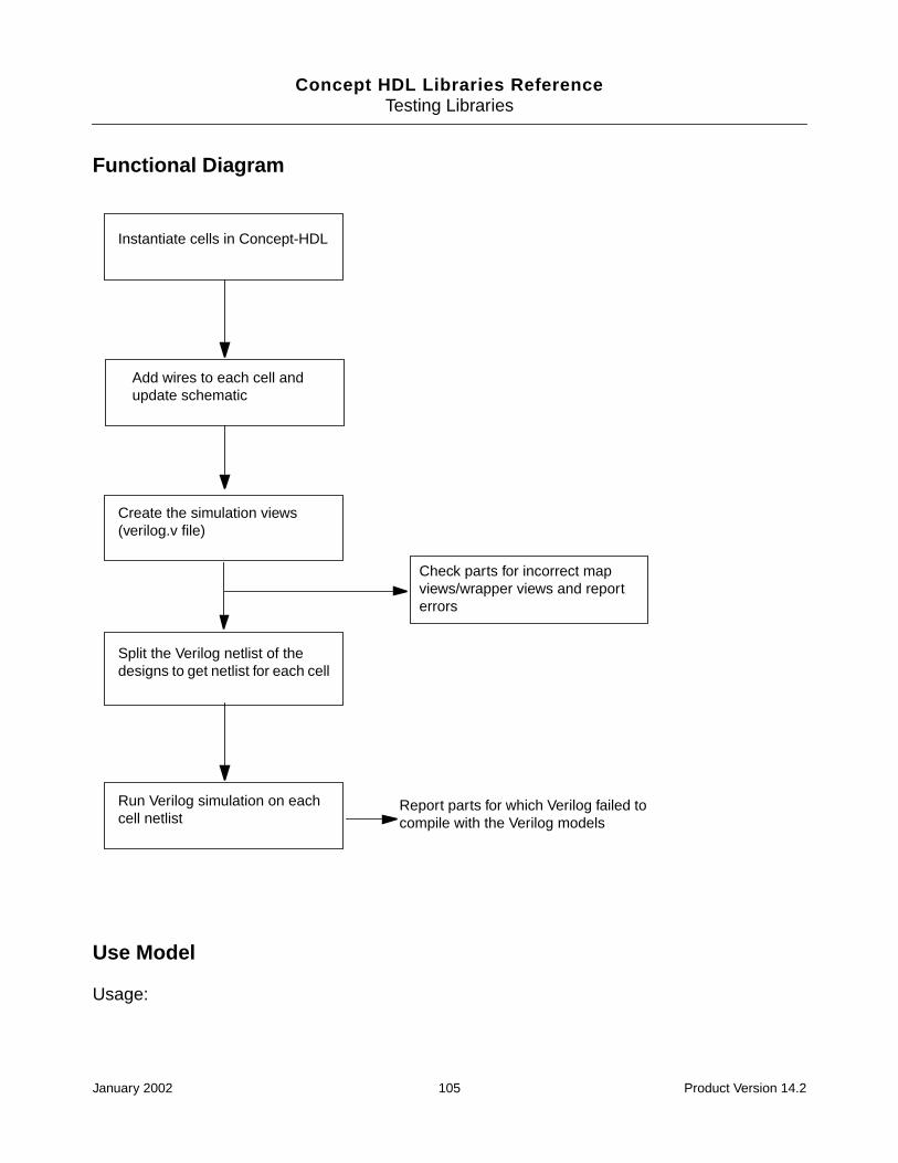
Concept HDL Libraries ReferenceTesting Libraries
Functional Diagram
Use Model
Usage:
Add wires to each cell andupdate schematic
Create the simulation views(verilog.v file)
Instantiate cells in Concept-HDL
Check parts for incorrect mapviews/wrapper views and reporterrors
Split the Verilog netlist of thedesigns to get netlist for each cell
Run Verilog simulation on eachcell netlist
Report parts for which Verilog failed tocompile with the Verilog models
January 2002 105 Product Version 14.2

Concept HDL Libraries ReferenceTesting Libraries
hlibsim-lib <Library> | -file <libList_filename>-vloptions <Verilog_model_path_filename> | -vlogmodeldir [default| <Name ofthe directory containing Verilog models>] | -sim OFF[-vlogudpdir <Name fo direcotry containing Verilog udps>][-libdir <Concept-HDL_lib_path>][-cell <cell 1> <cell 2> .....][-clean][-mapview <Names of the map view> | -wrapperview <Names of the wrapper view>]-product <Name of the product>
Usage Explanation
-lib <Library> Use this option to provide the name of theConcept-HDL library that is to be tested. Itslocation is passed through -libdir option.
-file <libList_filename> This option invokes testing in multiple librarymode. A file should contain one library per line.If this option is used, then the -lib option is notrequired.
-vloptions<Verilog_model_path_filename>
This option must be used to specify the filenamethat contains the path of respective librariescontaining the Verilog models. This option ismutually exclusive with the -sim OFF option.
-vlogmodeldir [default| <Nameof the directory containingVerilog models>
This option must be used to specify the path tothe Verilog model libraries. This option ismutually exclusive with the -sim OFF option. Ifyou do not specify the path to the directory thenhlibsim looks for a fie calledvlog_model_path.txt under the librarydirectory. This file should contain the path to theVerilog models.
-sim OFF Use this option to turn off the simulation for theselected library. This option is mutuallyexclusive with the -vloptions and -vlogmodeldir options.
If you use this switch, hlibsim proceeds onlyupto the netlisting and Verilog is not called.
-vlogudpdir <Name fo direcotrycontaining Verilog udps>
Use this option to specify the path to thedirectory containing the Verilog UDPs.
January 2002 106 Product Version 14.2
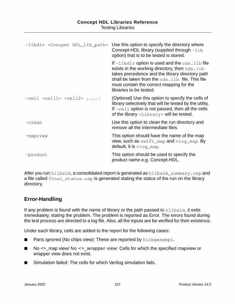
Concept HDL Libraries ReferenceTesting Libraries
After you run hlibsim, a consolidated report is generated as hlibsim_summary.rep anda file called final_status.rep is generated stating the status of the run on the librarydirectory.
Error-Handling
If any problem is found with the name of library or the path passed to hlibsim, it exitsimmediately, stating the problem. The problem is reported as Error. The errors found duringthe test process are directed to a log file. Also, all the inputs are be verified for their existence.
Under each library, cells are added to the report for the following cases:
■ Parts ignored (No chips view): These are reported by hlibgenxmpl.
■ No <>_map view/ No <>_wrapper view: Cells for which the specified mapview orwrapper view does not exist.
■ Simulation failed: The cells for which Verilog simulation fails.
-libdir <Concpet HDL_lib_path> Use this option to specify the directory whereConcept-HDL library (supplied through -liboption) that is to be tested is stored.
If -libdir option is used and the cds.lib fileexists in the working directory, then cds.libtakes precedence and the library directory pathshall be taken from the cds.lib file. This filemust contain the correct mapping for thelibraries to be tested.
-cell <cell1> <cell2> .... : (Optional) Use this option to specify the cells oflibrary selectively that will be tested by the utility.If -cell option is not passed, then all the cellsof the library <Library> will be tested.
-clean Use this option to clean the run directory andremove all the intermediate files.
-mapview This option should have the name of the mapview, such as swift_map and vlog_map. Bydefault, it is vlog_map.
-product This option should be used to specify theproduct name e.g. Concept-HDL.
January 2002 107 Product Version 14.2

Concept HDL Libraries ReferenceTesting Libraries
■ Syntax Error in Mapfile: These are the cells for which errors are reported bynewgenasym.
■ Wrapperfile Errors: These are the cells for which the errors are reported bynewgenasym.
■ Crossview Errors: These cells have crossview errors reported by newgenasym.
■ Others: These are the cells for which newgenasym did not report any errors butnetassembler did.
■ Can not test these: These are cells for which the model names are incorrect or thewrapper has errors.
Example
The hlibsim utility is run on the ls00 component of the lsttl library with the Concept-HDLproduct.
hlibsim -libdir ~cdsmgr/SUTTER/sun4v/share/library -lib lsttl -cell ls00 -sim off-product CONCEPTHDL -mapview swift_map
The output will look like:
See detailed log under:map_error_log - for any syntax or crossview errors inmapfiles.wrapper_error_log - for any syntax or crossview errors inwrapperfiles.sim_error_log - for any problems in simulation of parts with verilog models.
Library: lsttl---------------
Simulation Failed : ( )Mapfile Errors : ( )Parts Ignored (No Chips View) : ( )Mapview not found : ( )No mapfile found in view : ( )
January 2002 108 Product Version 14.2

Concept HDL Libraries ReferenceTesting Libraries
hlibftb
Overview
The hlibftb utility goes a step beyond the hlibgenxmpl utility and packages thegenerated design sheet(s).
The hlibftb utility invokes the hlibgenxmpl utility to instantiate cells of a Concept-HDLlibrary on a design sheet using Concept-HDL. The hlibgenxmpl utility creates one designsheet for each package type. All the cells supporting a particular package type areinstantiated on the sheet of that package type. For each such created design sheet,hlibgenxmpl makes a .cpm file, which it saves in the working directory.
After running hlibgenxmpl, hlibftb invokes Packager XL to package each of the designscreated by hlibgenxmpl. Then, hlibftb performs the following steps:
■ Checks the hdldir.log, pxl.log and edbconfig.log files for errors.
■ Checks whether the schematic view has non-zero verilog.v and .sir files.
■ Checks whether the packaged view has non-zero .dat files.
■ If hlibftb is used with the -netrev option, then it invokes Allegro to create an emptyboard and netrev. hlibftb then uprevs the board with the netlist, and creates a physicalview. After creating a physical view, hlibftb checks the presence of the netrev.lstand .brd files in the physical view. Then hlibftb reports the result in the ftb.repfile.
■ Reports the result of the test on the library in a report file called ftb.rep. The report fileis created in the current working directory.
■ Declares the test library as passed, if the Concept-HDL and the PXL run are successful.
■ Reports the nature of a failure in the ftb.rep file, if any errors occur in the Concept-HDL run or at the PXL run.
The hlibftb utility loads all the .ptf files specified in the ptfdirective file, and scans themfor rows corresponding to the part concerned. If the rows have the given PACK_TYPEproperty as the key property, then all the other key properties get added to the part. Thehlibftb utility checks the properties being added to ensure that the properties are notduplicated in the corresponding symbol.css file.
hlibftb then packages the design, and checks the o/ps. If the o/ps are successful, thedesign is netreved from the created .pst file.
January 2002 109 Product Version 14.2

Concept HDL Libraries ReferenceTesting Libraries
hlibftb also performs the following tasks:
■ It checks whether pack_type is present in ptf files, but not in the chips.prt file.
■ It ensures that if the pack_type property on it is conflicting, then the symbol is notinstantiated for a particular pack type. In other words, it skips the parts if the pack_typeproperty on it is in conflict.
■ It checks if pack type is a part of the primitive name in the chips.prt file.
Improvements in the PSD 14.0 Release
There are a number of enhancements in the PSD 14.0 release of hlibftb. They are:
■ Ability to handle technology-independent parts.
■ Ability to handle underscores in pack types. Previously, for a cell named as240 with aprimitive entry ‘74AS240_DIP_PWR’, hlibftb used to take PWR as the packtype.
■ Ability to handle hyphenated names in packtypes.
■ Ability to handle large pin count parts.
■ Ability to handle large parts.
■ Ability to handle partial names in pack primitives. Some chips have partial names in theirpack primitives, for example
primitive ‘74ABTH2545’,’ABTH25245’,’ABTH25245_SOIC’;
■ Ability to handle the VALID_PACK_TYPE property.
Use Model
Single Library Mode
hlibftb-lib <Library>[ -libdir <lib_dirname> ][ -cell <cell1> <cell2>... ][-pack <dip|soic|...|all|default>][-ptfdirectivefile][-advopt <opt_file_path>[-PSMPATH <‘path1’> <‘path2’>... ][-PADPATH <‘path1’><‘path2’>... ][-product <suitname>]]
January 2002 110 Product Version 14.2
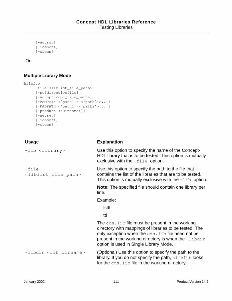
Concept HDL Libraries ReferenceTesting Libraries
[-netrev][-iconoff][-clean]
-Or-
Multiple Library Mode
hlibftb-file <liblist_file_path>[-ptfdirectivefile][-advopt <opt_file_path>][-PSMPATH <‘path1’> <‘path2’>...][-PADPATH <‘path1’><‘path2’>... ][-product <suitname>]][-netrev][-iconoff][-clean]
Usage Explanation
-lib <library> Use this option to specify the name of the Concept-HDL library that is to be tested. This option is mutuallyexclusive with the -file option.
-file<liblist_file_path>
Use this option to specify the path to the file thatcontains the list of the libraries that are to be tested.This option is mutually exclusive with the -lib option.
Note: The specified file should contain one library perline.
Example:
lsttl
ttl
The cds.lib file must be present in the workingdirectory with mappings of libraries to be tested. Theonly exception when the cds.lib file need not bepresent in the working directory is when the -libdiroption is used in Single Library Mode.
-libdir <lib_dirname> (Optional) Use this option to specify the path to thelibrary. If you do not specify the path, hlibftb looksfor the cds.lib file in the working directory.
January 2002 111 Product Version 14.2

Concept HDL Libraries ReferenceTesting Libraries
Example
Following is an example of the hlibftb being run on the ls00 component of the lsttl libraryusing the Concept-HDL product.
hlibftb -libdir ~cdsmgr/BRETON/sun4v/share/library -lib lsttl -cell ls00 -productCONCEPTHDL -PSMPATH ~cdsmgr/BRETON/sun4v/share/pcb/pcb_lib/symbols -PADPATH~cdsmgr/BRETON/sun4v/share/pcb/pcb_lib/symbols -netrev
-cell <cell1> <cell2>... (Optional) Use this option to specify the cells that needto be tested. If the cells to be tested are not specified,hlibftb tests all the cells in the specified library.
Note: This option cannot be used with the -fileoption.
-pack<dip|soic|...|all|default>
(Optional) Use this option to specify the pack types tobe tested. The default value for this option is “default”.
Note: This option cannot be used with the -fileoption.
-ptfdirectivefile (Optional) Use this option to specify the path to theptfdirective file.
-advopt (Optional) Use this option to specify the path to theoptions file.
-PSMPATH <‘path1‘><‘path2‘>...
(Optional) Use this option to specify the path to theAllegro symbols.
- PADPATH <‘path1‘><‘path2‘>...
(Optional) Use this option to specify the path to theAllegro pads.
-product <suitename> (Optional) Use this option to specify the product name,such as Concept-HDL.
-netrev (Optional) Use this option to invoke Allegro and takethe design up to the netrev stage.
-iconoff (Optional) Use this option to toggle display between theicon mode and the full screen mode of the tools as theyare executed while running hlibftb.
-clean (Optional) Use this option to clean up the designs thathave been tested.
January 2002 112 Product Version 14.2

Concept HDL Libraries ReferenceTesting Libraries
The output will look as shown below:
hlibchk
Overview
The hlibchk utility checks the presence of all parts in the .cat file, checks the existence ofall views in the parts of a library, checks the syntax of view files, and verifies that the Allegrolibraries contain the JEDEC_TYPE mentioned in the chips view. Apart from these functions,hlibchk also performs a check for "HDL"/ "Comment Body" properties for non-physicalparts.
Single Library Mode
hlibchk-lib <Library>[-libdir <Concept-HDL_lib_dirname>][-cell <cell1> <cell2> ......][-PSMPATH <Allegro_lib_path>][-simswitch]
Multiple Library Mode
hlibchk-file <Liblist_file_path>-PSMPATH <Allegro_lib_path>[-simswitch]
January 2002 113 Product Version 14.2

Concept HDL Libraries ReferenceTesting Libraries
Functional Diagram
Use Model
Following is the use model for the hlibchk utility:
Single Library Mode
hlibchk-lib <Library>[-libdir <Concept-HDL_lib_dirname>][-cell <cell1> <cell2> ......][-PSMPATH <Allegro_lib_path>][-simswitch]
Multiple Library Mode
hlibchk-file <Liblist_file_path>-PSMPATH <Allegro_lib_path>[-simswitch]
Check presence in cat
Check views
Verify chips for JEDEC_TYPE
Verify non-physical
Verify that all parts find entry in the .cat file
Verify that all views exist and have the required files
Verify chips for JEDEC_TYPE and its existence in theAllegro library
Presence of HDL property in parts without chips
Report
January 2002 114 Product Version 14.2
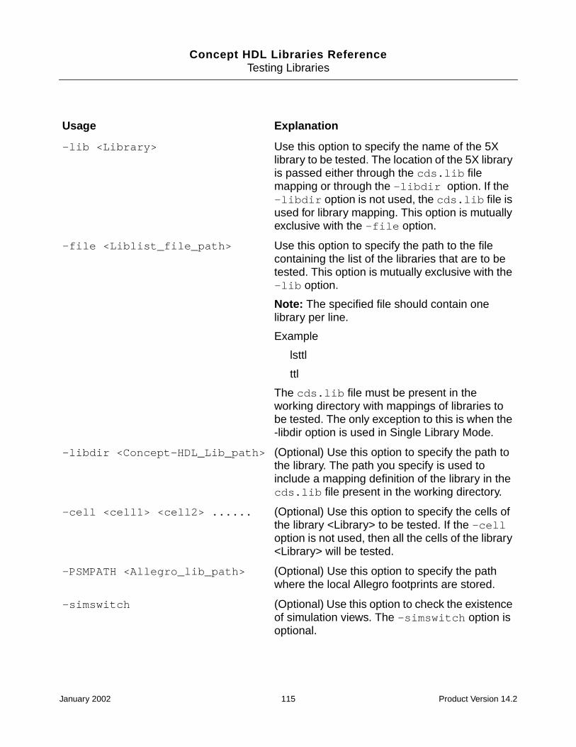
Concept HDL Libraries ReferenceTesting Libraries
Usage Explanation
-lib <Library> Use this option to specify the name of the 5Xlibrary to be tested. The location of the 5X libraryis passed either through the cds.lib filemapping or through the -libdir option. If the-libdir option is not used, the cds.lib file isused for library mapping. This option is mutuallyexclusive with the -file option.
-file <Liblist_file_path> Use this option to specify the path to the filecontaining the list of the libraries that are to betested. This option is mutually exclusive with the-lib option.
Note: The specified file should contain onelibrary per line.
Example
lsttl
ttl
The cds.lib file must be present in theworking directory with mappings of libraries tobe tested. The only exception to this is when the-libdir option is used in Single Library Mode.
-libdir <Concept-HDL_Lib_path> (Optional) Use this option to specify the path tothe library. The path you specify is used toinclude a mapping definition of the library in thecds.lib file present in the working directory.
-cell <cell1> <cell2> ...... (Optional) Use this option to specify the cells ofthe library <Library> to be tested. If the -celloption is not used, then all the cells of the library<Library> will be tested.
-PSMPATH <Allegro_lib_path> (Optional) Use this option to specify the pathwhere the local Allegro footprints are stored.
-simswitch (Optional) Use this option to check the existenceof simulation views. The -simswitch option isoptional.
January 2002 115 Product Version 14.2

Concept HDL Libraries ReferenceTesting Libraries
Example
Following is an example of the hlibchk being run on the ls00 component of the lsttl libraryusing the Concept-HDL product.
hlibchk -libdir ~cdsmgr/SUTTER/sun4v/share/library -lib lsttl -cell ls00 -PSMPATH~cdsmgr/SUTTER/sun4v/share/pcb/pcb_lib/symbols
The output is displayed below:
January 2002 116 Product Version 14.2
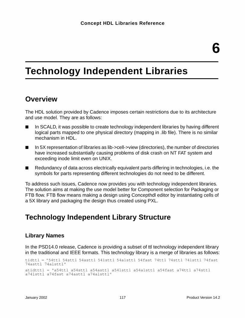
Concept HDL Libraries Reference
6Technology Independent Libraries
Overview
The HDL solution provided by Cadence imposes certain restrictions due to its architectureand use model. They are as follows:
■ In SCALD, it was possible to create technology independent libraries by having differentlogical parts mapped to one physical directory (mapping in .lib file). There is no similarmechanism in HDL.
■ In 5X representation of libraries as lib->cell->view (directories), the number of directorieshave increased substantially causing problems of disk crash on NT FAT system andexceeding inode limit even on UNIX.
■ Redundancy of data across electrically equivalent parts differing in technologies, i.e. thesymbols for parts representing different technologies do not need to be different.
To address such issues, Cadence now provides you with technology independent libraries.The solution aims at making the use model better for Component selection for Packaging orFTB flow. FTB flow means making a design using Concepthdl editor by instantiating cells ofa 5X library and packaging the design thus created using PXL.
Technology Independent Library Structure
Library Names
In the PSD14.0 release, Cadence is providing a subset of ttl technology independent libraryin the traditional and IEEE formats. This technology library is a merge of libraries as follows:
tidttl = "54ttl 54sttl 54asttl 54lsttl 54alsttl 54fast 74ttl 74sttl 74lsttl 74fast74asttl 74alsttl"
atidtttl = "a54ttl a54sttl a54asttl a54lsttl a54alsttl a54fast a74ttl a74sttla74lsttl a74fast a74asttl a74alsttl"
January 2002 117 Product Version 14.2

Concept HDL Libraries ReferenceTechnology Independent Libraries
Naming of Parts
The technology independent library tidttl is stored in the same location as the other libraries,i.,e in <your_install_dir>/share/library
The parts of technology independent library are named as
<technology_bundle_name>_<generic_part_name>
Example: ttl_00
The <library>.cat FIle
Similar to technology dependent libraries, this file contains the classification of the libraryparts by functional categories. However, the category file shall have functional categorizationindependent of technology with the names of the cells valid in Concept namespace (nmpmapping of physical cell directories to Concept namespace).
Example for ttl bundle:
"ADDER"
{
"1-BIT"
{
"TTL_183"
}
"4-BIT"
January 2002 118 Product Version 14.2
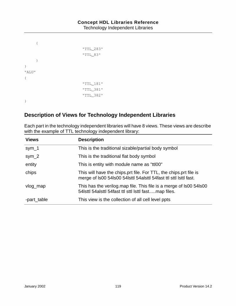
Concept HDL Libraries ReferenceTechnology Independent Libraries
{
"TTL_283"
"TTL_83"
}
}
"ALU"
{
"TTL_181"
"TTL_381"
"TTL_382"
}
Description of Views for Technology Independent Libraries
Each part in the technology independent libraries will have 8 views. These views are describewith the example of TTL technology independent library:
Views Description
sym_1 This is the traditional sizable/partial body symbol
sym_2 This is the traditional flat body symbol
entity This is entity with module name as "ttl00"
chips This will have the chips.prt file. For TTL, the chips.prt file ismerge of ls00 54ls00 54lsttl 54alsttl 54fast ttl sttl lsttl fast.
vlog_map This has the verilog.map file. This file is a merge of ls00 54ls0054lsttl 54alsttl 54fast ttl sttl lsttl fast.....map files.
-part_table This view is the collection of all cell level ppts
January 2002 119 Product Version 14.2

Concept HDL Libraries ReferenceTechnology Independent Libraries
Accessing Technology Independent Parts
Technology independent parts can be accessed through the component browser. In Concept,choose Component > Add to get the list of libraries. The technology independent tidttlappears along with the other libraries.
Note: Do not use components from tidttl and other ttl libraries in the mix.
Note: The hlibsim library testing utility will not work with the technology-independentlibraries.
Technology Independent Libraries in the FTB (PXL) Flow
Property Annotation for PXL
On selection of the primitive, the corresponding rows in ppt are shown if the ppt exists. Onselection of the ppt row for chosen primitive, the key properties should be annotated along
January 2002 120 Product Version 14.2

Concept HDL Libraries ReferenceTechnology Independent Libraries
with the PART_NAME. In the absence of ppt information, only the PART_NAME value shouldget annotated.
chips View
The example below shows how physical parts are created when the chips file contains twoPART_NAME properties with different values (in this case representative of two differenttechnologies)
FILE_TYPE=LIBRARY_PARTS;
primitive '74LS00','74LS00_DIP';
pin
'B'<0>:
INPUT_LOAD='(-0.4,0.02)';
PIN_NUMBER='(13,10,5,2)';
PIN_GROUP='1';
'A'<0>:
INPUT_LOAD='(-0.4,0.02)';
PIN_NUMBER='(12,9,4,1)';
PIN_GROUP='1';
'-Y'<0>:
OUTPUT_LOAD='(8.0,-0.4)';
PIN_NUMBER='(11,8,6,3)';
end_pin;
body
POWER_PINS='(VCC:14;GND:7)';
PART_NAME='74LS00';
BODY_NAME='ttl00';
JEDEC_TYPE='DIP14_3';
CLASS='IC';
TECH='74LS';
end_body;
end_primitive;
primitive '74LS00_SOIC';
pin
'B'<0>:
INPUT_LOAD='(-0.4,0.02)';
PIN_NUMBER='(13,10,5,2)';
PIN_GROUP='1';
'A'<0>:
INPUT_LOAD='(-0.4,0.02)';
January 2002 121 Product Version 14.2
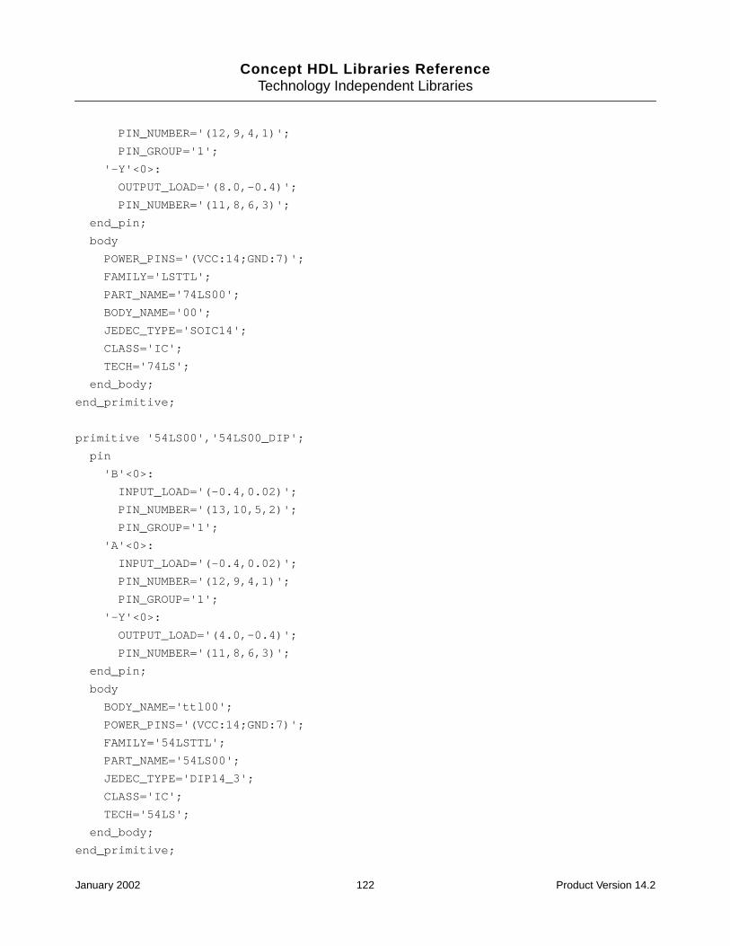
Concept HDL Libraries ReferenceTechnology Independent Libraries
PIN_NUMBER='(12,9,4,1)';
PIN_GROUP='1';
'-Y'<0>:
OUTPUT_LOAD='(8.0,-0.4)';
PIN_NUMBER='(11,8,6,3)';
end_pin;
body
POWER_PINS='(VCC:14;GND:7)';
FAMILY='LSTTL';
PART_NAME='74LS00';
BODY_NAME='00';
JEDEC_TYPE='SOIC14';
CLASS='IC';
TECH='74LS';
end_body;
end_primitive;
primitive '54LS00','54LS00_DIP';
pin
'B'<0>:
INPUT_LOAD='(-0.4,0.02)';
PIN_NUMBER='(13,10,5,2)';
PIN_GROUP='1';
'A'<0>:
INPUT_LOAD='(-0.4,0.02)';
PIN_NUMBER='(12,9,4,1)';
PIN_GROUP='1';
'-Y'<0>:
OUTPUT_LOAD='(4.0,-0.4)';
PIN_NUMBER='(11,8,6,3)';
end_pin;
body
BODY_NAME='ttl00';
POWER_PINS='(VCC:14;GND:7)';
FAMILY='54LSTTL';
PART_NAME='54LS00';
JEDEC_TYPE='DIP14_3';
CLASS='IC';
TECH='54LS';
end_body;
end_primitive;
January 2002 122 Product Version 14.2

Concept HDL Libraries ReferenceTechnology Independent Libraries
The file defines two logical parts, in this case 74LS00 and 54LS00. Three primitive entrieswhose name begin with 74LS00 cause three physical parts to be created for the logical part74LS00: 74LS00, 74LS00_DIP, 74LS00_SOIC. Two primitive entries whose name begin with54LS00 cause two physical parts to be created for logical part 54LS00: 54LS00_DIP.
In absence of the PART_NAME property, PXL takes the shortest primitive which in abovecase would be 74LS00 and 54LS00 and the two would be treated as logical parts. Otherprimitives in the corresponding same sections are compared with these logical names to findthe common base and they become the physical parts.
In this case 74LS00_DIP is physical part with logical name 74LS00, but 74LS00_SOIC wouldnot be the physical part of 74LS00 as it does not lie in the same primitive section.
This makes it mandatory for PART_NAME to exist in each of the primitives which are PACKderivatives of one logical(technology) part.
PPT View
In a PPT, if a part whose name matches the logical part name for the schematic instanceexists, then it is used with the schematic instance. Only in absence of such table, the searchis done by physical name (logical name with an underscore PACK_TYPE suffix) providedPACK_TYPE exists on the instance.
The PPT for a technology independent part shall need to have sections corresponding toeach technology (logical) part as follows:
FILE_TYPE = MULTI_PHYS_TABLE;
PART '74LS00'
CLASS = IC
{=====================================================}
:PACK_TYPE(OPT='DIP') | PART_NUMBER(OPT='123_XXXXXX') = PART_NUMBER | JEDEC_TYPE |COST | DESCRIPTION ;
{====================================================}
DIP | 123_XXXXXX(!) = 123_XXXXXX | DIP14_3 | $| PREFERRED
END_PART
PART '54LS00'
CLASS = IC
{====================================================}
:PACK_TYPE(OPT='DIP') | PART_NM(OPT='123_XXXXXX') = PART_NUMBER | JEDEC_TYPE | COST| DESCRIPTION ;
{====================================================}
January 2002 123 Product Version 14.2
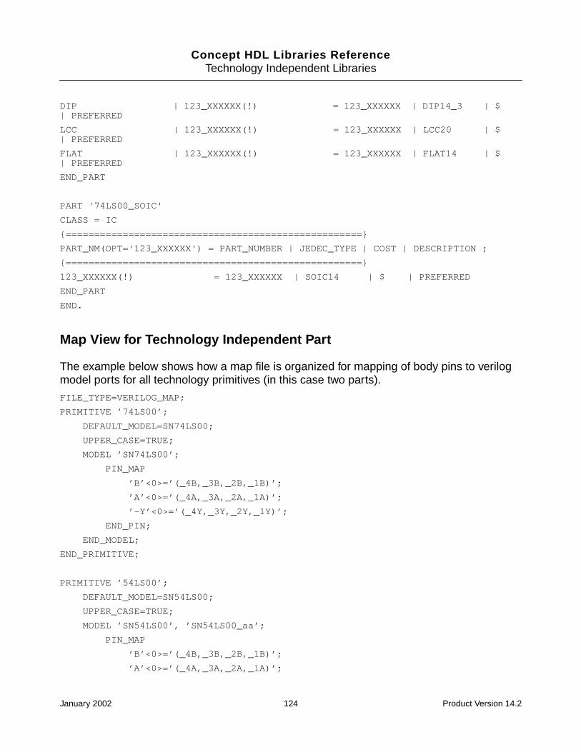
Concept HDL Libraries ReferenceTechnology Independent Libraries
DIP | 123_XXXXXX(!) = 123_XXXXXX | DIP14_3 | $| PREFERRED
LCC | 123_XXXXXX(!) = 123_XXXXXX | LCC20 | $| PREFERRED
FLAT | 123_XXXXXX(!) = 123_XXXXXX | FLAT14 | $| PREFERRED
END_PART
PART '74LS00_SOIC'
CLASS = IC
{====================================================}
PART_NM(OPT='123_XXXXXX') = PART_NUMBER | JEDEC_TYPE | COST | DESCRIPTION ;
{====================================================}
123_XXXXXX(!) = 123_XXXXXX | SOIC14 | $ | PREFERRED
END_PART
END.
Map View for Technology Independent Part
The example below shows how a map file is organized for mapping of body pins to verilogmodel ports for all technology primitives (in this case two parts).
FILE_TYPE=VERILOG_MAP;
PRIMITIVE ’74LS00’;
DEFAULT_MODEL=SN74LS00;
UPPER_CASE=TRUE;
MODEL ’SN74LS00’;
PIN_MAP
’B’<0>=’(_4B,_3B,_2B,_1B)’;
’A’<0>=’(_4A,_3A,_2A,_1A)’;
’-Y’<0>=’(_4Y,_3Y,_2Y,_1Y)’;
END_PIN;
END_MODEL;
END_PRIMITIVE;
PRIMITIVE ’54LS00’;
DEFAULT_MODEL=SN54LS00;
UPPER_CASE=TRUE;
MODEL ’SN54LS00’, ’SN54LS00_aa’;
PIN_MAP
’B’<0>=’(_4B,_3B,_2B,_1B)’;
’A’<0>=’(_4A,_3A,_2A,_1A)’;
January 2002 124 Product Version 14.2
Concept HDL Libraries ReferenceTechnology Independent Libraries
’-Y’<0>=’(_4Y,_3Y,_2Y,_1Y)’;
END_PIN;
END_MODEL;
END_PRIMITIVE;
END.
January 2002 125 Product Version 14.2

Concept HDL Libraries ReferenceTechnology Independent Libraries
January 2002 126 Product Version 14.2
Concept HDL Libraries Reference
7Reference Libraries
The Standard Library
The “standard library” contains parts that have no logic function or physical meaning. Theseparts are used either to convey design information to the Compiler, Simulator, and Packager-XL, or to make the schematic more concisely represent the design. Each part in this libraryis a body that can be added to a drawing of any type. The following parts (bodies) are in thestandard library:
A SIZE PAGE, B SIZE PAGE, C SIZE PAGE, D SIZE PAGE, E SIZE PAGE andF SIZE PAGE
A SIZE PAGE, B SIZE PAGE, C SIZE PAGE, D SIZE PAGE, E SIZE PAGE, and F SIZE PAGEare borders placed around a drawing. These borders provide a space for the engineer’sname, the date, and notes, but do not have any other significance and are not mandatory ina schematic, unless you use the CRefer, in which case a page border is required.
CADENCE A SIZE PAGE and CADENCE B SIZE PAGE
CADENCE A SIZE PAGE and CADENCE B SIZE PAGE are also borders that can be placedaround drawings. These borders include the Cadence logo and copyright statement, but donot have any other significance and are not mandatory in a schematic, unless you use theCRefer, in which case a page border is required. You can use the CADENCE A SIZE or BSIZE page borders for Cadence-supplied models and drawings.
CONN_BRK and CONN_GEN
You can use the conn_brk and conn_gen library bodies to create connectors in the schematic.Load the sizable pin (one pin sizable connector) as many times as the number of pinsrequired and assign the pin_number to the $PN property of each connector pin.
January 2002 127 Product Version 14.2
Concept HDL Libraries ReferenceReference Libraries
DEFINE
You use DEFINE to define text macros that are specified as properties of this body. Theproperty name is the text macro name with the value as its definition.
DRAWING
You use DRAWING to attach properties to the entire drawing. Examples of bodies attachedto DRAWING are “TITLE=xxx” and “ABBREV=xxx.”
FLAG
You can add FLAG symbols to interface signals to indicate the physical pins of a design. Flagsymbols are usually not required. However, they are required as Packager-XL output by somephysical design systems.
GND_EARTH
This is a chassis or frame ground. This is normally provided as protective GND for any circuitfault. This is also called protective earth.
GND_SIGNAL
For all the signal connections on a PCB, this provides the point of reference. This is keptseparate for POWER ground as the switching activity on this can copuple into other ground.In a single point grounding scheme, this is connected to POWER ground at a single point.
GROUND
In absence of a specific mention by the designer, this is used in a general design. It does notdistinguish between different types of grounds.
GND_FIELD
This is used with any circuit which generates radiated fields, such as RF transmitters.
January 2002 128 Product Version 14.2

Concept HDL Libraries ReferenceReference Libraries
MERGE/CONCAT
You use MERGE symbols to combine a number of separate signals into a signal vectoredsignal, or to separate a vectored signal into a number of signals. This allows you to draw thevectored signal (the bus) as a single wire in parts of the drawing, and to draw it as severalsignals in other parts of the drawing. For example, an address bus called ABUS<15..0> canbe made up of ABUS<8..0> connected to a memory device, and ABUS<10..9>,ABUS<12..11>, and ABUS <15..13> connected to decoders and other control devices.
You can use a 4 MERGE merge symbol to draw each of the four signals separately on onepart of the drawing, and then merge them into a bus in another part of the design. This mergefunction is performed by synonyming the single signal name with the concatenation of theother signal names. Each merge symbol has four versions-two for merges and two fordemerges. Versions 1 and 2 have inputs on 0.2-inch centers and versions 3 and 4 have inputson 0.1-inch centers. Each merge symbol accepts different number of input signals to beconcatenated together.
You can also define other merge symbols. The HDL_CONCAT property attached to the originof the symbol classifies the given symbol as MERGE.
The versions of the 2, 4, 6, 8, and 10 merge symbols having inputs on 0.1-inch centers haveoutputs off the grid. To connect a wire to these points, use the right button on the mouse.Using versions 2, 4, 6, 8, or 10 is not advisable if you are using a tool that assumes that pinsare on the grid.
MSB TAP, LSB TAP, BIT TAP, and TAP
The TAP symbols are used to extract, or break out, a single bit from a vectored signal. Thefour TAP bodies are:
■ MSB TAP, which extracts the most significant bit from the signal.
■ LSB TAP, which extracts the least significant bit from the signal.
■ BIT TAP, which uses a relative bit number to extract a single bit from a bus.
■ TAP, which uses an actual bit number to extract a single bit from a bus.
For MSB TAP and LSB TAP, the SIZE property specifies the width of the signal to extract.
For BIT TAP, you must change the body property BIT to select any single bit from bit number0 to bit number <bus size>-1.
For TAP, you must change the body property BN to select any single bit of a bus.
January 2002 129 Product Version 14.2

Concept HDL Libraries ReferenceReference Libraries
The HDL_TAP property attached to the origin of the symbol classifies the given symbol asTAP.
The TAP symbol is the easiest to use tap body. The <standard> TAP symbols have the sameversions/rotations as the <tscr>TAP. The <standard>BIT TAP has the BN property attachedto the body, and only has four versions that are graphically different than the <tscr>BIT TAP.The <tscr>BIT TAP has eight versions with the BN property attached to the PIN.
It is recommended that users should primarily use the TAP body.
NOT
The NOT symbol supports the bubble checker features of the compiler. The NOT body is seenonly by the bubble checker. It does not change the assertion of a signal. If the bubble checkeris turned off, the signals on either side of the NOT symbol are synonymed together and theNOT symbol is otherwise ignored.
The NOT symbol is used to convert a signal from one assertion to the other for the BubbleChecker without a logical inversion taking place.
The HDL_NOT property attached to the origin of symbol classifies the given symbol as NOT.
ORIGIN
Concept-HDL automatically uses this symbol to indicate the origin of any symbol. You do notadd the ORIGIN symbol manually to a drawing. When you edit a .SYMBOL drawing, an originsymbol (a small X) appears at the center of the screen.
PIN NAMES
You use the PIN NAMES symbol for hierarchical design and library development. The signalnames can be moved and reattached to the hierarchical symbol and the PIN NAMES symbolcan then be deleted. The use of the PIN NAMES symbol eliminates the need to retype thesignal names or omit the local scope (\) signal property.
REPLICATE
You use the REPLICATE symbol when making models for sizeable parts. Library developersusually add this symbol to .SIM drawings. The HDL_REPLICATE property attached to theorigin of the symbol classifies the given symbol as REPLICATE.
January 2002 130 Product Version 14.2
Concept HDL Libraries ReferenceReference Libraries
SIGN EXTEND
You use the SIGN EXTEND symbol to extend an n-bit signal to a SIZE-bit signal by replicatingthe sign bit. The SIZE property is attached to the symbol. The MSB (the most significant bit)of the signal is always extended.
SIM_DIRECTIVES
You use the SIM_DIRECTIVES symbol to pass directives to the Simulator. Propertiesattached to this symbol are Simulator directives. This symbol is used infrequently.
SLASH
You can add a SLASH symbol to a vectored signal to provide a visible note of the signal width.You also use it to check the width of the parent signal. When you attach a SLASH symbol,you change the value of the SIZE property attached to the symbol to the correct value. Thecompiler checks that the value of the SIZE property for the SLASH symbol matches the widthof the signal. If the two do not match, an error is generated. The HDL_SLASH propertyattached to the origin of the symbol classifies the given symbol as SLASH.
SYNONYM
The SYNONYM symbol is a symbol with two pins of the same name. Add the synonymsymbol in a corner of the drawing and use the SIGNAME command to attach the two signalnames to be synonymed to the two pins of the synonym symbol. The assertions of the twosignals must match and the signals must have the same width. The default propertyTERMINAL=TRUE in the synonym.logic drawing tells the Compiler that this is a terminaldrawing and does not have to be expanded.
When signals are synonymed together, they become aliases for each other. Both names referto the same physical signal (net). When a signal has a very long name, it is convenient to giveit a shorter name with a SYNONYM symbol.
Two signals are synonymed when the signal names are each connected to a pin of theSYNONYM symbol, or when the signal names are connected to the same pin of any symbol.The latter condition should be avoided. Bus-through pins are also implemented by theCompiler synonym function. Two distinct pins on the symbol are given the same name andthe signals connected to them are therefore synonymed together.
January 2002 131 Product Version 14.2

Concept HDL Libraries ReferenceReference Libraries
VCC_ARROW
This is a general power connection and is used for graphical notation. It can be any powerconnection such as power plane, a power track or any such power reference.
VCC_BAR
This is same as VCC_ARROW except for a different graphical representation.
VCC
This is a generic SUPPLY voltage indication and is used as a default by the designer.
VCC_CIRCLE
This is another variation of the basic VCC notation that used circle as the indication.
VCC_WAVE
This is a notation for applying a waveform in addition to a voltage source so that the compositewaveform is not a DC voltage.
Element Library
Overview
This library primarily contains the basic building blocks that are not part of other digitallibraries.
The type of cells can be classified into the following:
■ Resistor/Capacitor/Inductor/Transformer
■ Transistor (BJT, MOS), Diode
■ Generic Opamp, Opto-coupler
■ Voltage/current sources and other miscellaneous functions
January 2002 132 Product Version 14.2

Concept HDL Libraries ReferenceReference Libraries
Some of the parts in this library are taken from the bodies library. The chips.prt file is createdwherever needed.
Creating Ports
When creating an HDL Direct schematic, you must place port symbols on the page to indicatethe ports on the entity. Use the following symbols from the HDL Direct library:
■ INPORT
■ IOPORT
■ BUFPORT
■ OUTPORT
■ LNKPORT
■ AOUTPORT
After you place a port symbol, attach a wire to the pin on the port and then name the signal.This signal name is the port declaration in the VHDL and Verilog text. \I on a signal nameindicates that it is a port.
If the VHDL port type is not the same as the default type specified on your VHDL_DECSsymbol, you can attach one of the following properties to the wire:
■ VHDL_SCALAR_TYPE = scalar_typename
■ VHDL_VECTOR_TYPE = vector_typename
If the port is vectored, use the VHDL_VECTOR_TYPE property, otherwise use theVHDL_SCALAR_TYPE property.
If you plan to use custom port symbols instead of those supplied in the HDL Direct library,make sure to copy all the visible and invisible properties on the HDL Direct port symbols.
If a customized port symbol has additional properties attached to the pin, they are also copiedto the net attached to the port symbol when HDL Direct creates the SCALD connectivity file.
A VHDL and Verilog restriction prohibits you from wiring different ports of an entity together.HDL Direct gives a warning if different ports of an entity are wired together in your schematics.
January 2002 133 Product Version 14.2
Concept HDL Libraries ReferenceReference Libraries
VHDL Port Association Restrictions
The VHDL language has strict rules concerning the port associations allowed between portsof component instances within an architecture and the ports of the entity declaration.
Verilog port association rules are not as strict as VHDL. If you use the VHDL_USER=NOproperty on your VERILOG_DECS symbol, you do not need to follow the rules describedbelow.
A formal port is defined to be the port on an instance. An actual port is the port in the entitydescription.
For example, if a formal port is an INOUT port and that port is connected to ports higher upin the design hierarchy, the other ports must also be declared as INOUT ports. Likewise, if aBUFFER port is connected to ports higher up in the design hierarchy, the other ports mustalso be declared as BUFFER ports.
A common problem occurs when you want to read (within an architecture) the value of a portdeclared as an OUT. A port declared as an OUT can only be connected to ports on instancesthat are also declared as OUT. Therefore the value of the OUT port cannot be read by an INor INOUT port on an instance.
This restriction is made because an OUT port might have other drivers attached to it outsideof the architecture that affect the resolved signal value. By declaring an OUT port, theresolved signal value outside of the architecture cannot have any effect inside thearchitecture.
One way to read the value of an OUT port inside an architecture is by declaring the port asINOUT. Alternatively, you can use the HDL Direct AOUTPORT port to read the value of theOUT port.
Generating Entity Declarations from Symbols
Generating an Entity Declaration from Symbols
If the parts you are using do not have an entity declaration in the design library and you wantto use HDL Direct to generate entity declarations automatically, you can add properties toensure that an accurate entity declaration is generated. Typically, you make these propertiesinvisible in your symbol drawings. The properties can be set for:
■ Declaring VHDL or Verilog Generic Parameters
■ Declaring Port Modes
January 2002 134 Product Version 14.2
Concept HDL Libraries ReferenceReference Libraries
■ Declaring VHDL Logic Types of Ports
■ Declaring Verilog Logic Types of Ports
■ Declaring Port Ranges
■ Declaring Use Clauses
These properties are not mandatory. However, if the properties are missing, and the entitydeclaration is not present, HDL Direct might generate an inaccurate entity declaration.
Declaring VHDL or Verilog Generic Parameters
To define VHDL or Verilog generic parameters
Attach the following property to the origin of the symbol.
GENERICxx=name:type
Where:
xx is a unique number, name is the name of the generic parameter, and type is the genericparameter type.
Declaring Port Modes
By default, every port in a symbol drawing is assumed to be an input. For every port in yoursymbol that is not an input, place one of the following properties on one of the pins on the port.
MODE=OUT
MODE=INOUT
MODE=BUF
MODE=LINKAGE
If you have 32 pins that are part of the same port (for example, A(31), A(30), …A(0)) you needto put only one of the above properties on one of the pins of the port.
January 2002 135 Product Version 14.2

Concept HDL Libraries ReferenceReference Libraries
Declaring VHDL Logic type of Ports
To declare the VHDL logic type of a port
Attach one of the following properties to a pin on the port.
VHDL_SCALAR_TYPE = type
VHDL_VECTOR_TYPE = type
If the port is vectored, use the VHDL_VECTOR_TYPE property; otherwise use theVHDL_SCALAR_TYPE property.
To set the default VHDL logic type of all ports for a symbol
Attach one or both of the above properties to the origin of the symbol.
You might need to include both properties if the symbol has vectored and nonvectored ports.Ports that have their own VHDL_SCALAR_TYPE or VHDL_VECTOR_TYPE properties takeprecedence over the origin properties.
If no VHDL_SCALAR_TYPE or VHDL_VECTOR_TYPE properties are attached to the originof the symbol or to one of its pins, HDL Direct uses the following defaults:
VHDL_SCALAR_TYPE = STD_LOGIC
VHDL_VECTOR_TYPE = STD_LOGIC_VECTOR
Declaring Verilog type of ports
To declare the Verilog logic type of a port
Attach the VLOG_NET_TYPE property to a pin on the port. Legal values of theVLOG_NET_TYPE property include WAND and WAR.
To set the default Verilog logic type of all ports for a symbol
Attach the VLOG_NET_TYPE property to the origin of the symbol. Legal values of theVLOG_NET_TYPE property include WAND and WAR.
January 2002 136 Product Version 14.2

Concept HDL Libraries ReferenceReference Libraries
Declaring Port ranges
HDL Direct examines all the pins that make up a port to determine the range of the port. Forexample, if pins SEL(1) and SEL(0) exist, HDL Direct declares a port SEL(1 down to 0). Youmight need to define the range of a port when there is insufficient information in the pinnames. For example, if SEL is a "sizeable" port and is declared as SEL (size - 1:0), but the symbolyou are creating is a "fixed size" version that has only the pins SEL(1) and SEL(0) in it, attachthe following property to one of the SEL pins.
RANGE = size - 1:0
This specifies the correct range for the port.
Declaring Libraries
To generate library clauses from a Concept-HDL body symbol drawing
Attach the following property to the origin of the symbol:
LIBRARYxx=libname
xx is a unique number and libname is the name of the library.
Declaring Use Clauses
To generate use clauses from a Concept-HDL body symbol drawing
Attach the following property to the origin of the symbol:
USExx=libname
xx is a unique number and libname is the name of the library.
For example, to ensure that the entity can access all names declared within theIEEE.std_logic_a1164 package in the library IEEE, give the property
USE LIBRARY = IEEE.std_logic_1164.ALL
This ensures that the following two entries are added to the entity declaration of the part:
LIBRARY IEEE;
USE IEEE.std_logic_1164.ALL;
January 2002 137 Product Version 14.2
Concept HDL Libraries ReferenceReference Libraries
January 2002 138 Product Version 14.2
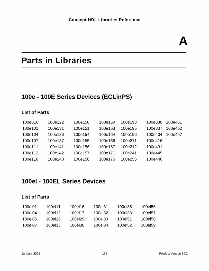
Concept HDL Libraries Reference
AParts in Libraries
100e - 100E Series Devices (ECLinPS)
List of Parts
100el - 100EL Series Devices
List of Parts
100e016 100e122 100e150 100e160 100e193 100e336 100e451
100e101 100e131 100e151 100e163 100e195 100e337 100e452
100e104 100e136 100e154 100e164 100e196 100e404 100e457
100e107 100e137 100e155 100e166 100e211 100e416
100e111 100e141 100e156 100e167 100e212 100e431
100e112 100e142 100e157 100e171 100e241 100e445
100e116 100e143 100e158 100e175 100e256 100e446
100el01 100el11 100el16 100el31 100el35 100el56
100el04 100el12 100el17 100el32 100el38 100el57
100el05 100el13 100el29 100el33 100el51 100el58
100el07 100el15 100el30 100el34 100el52 100el59
January 2002 139 Product Version 14.2
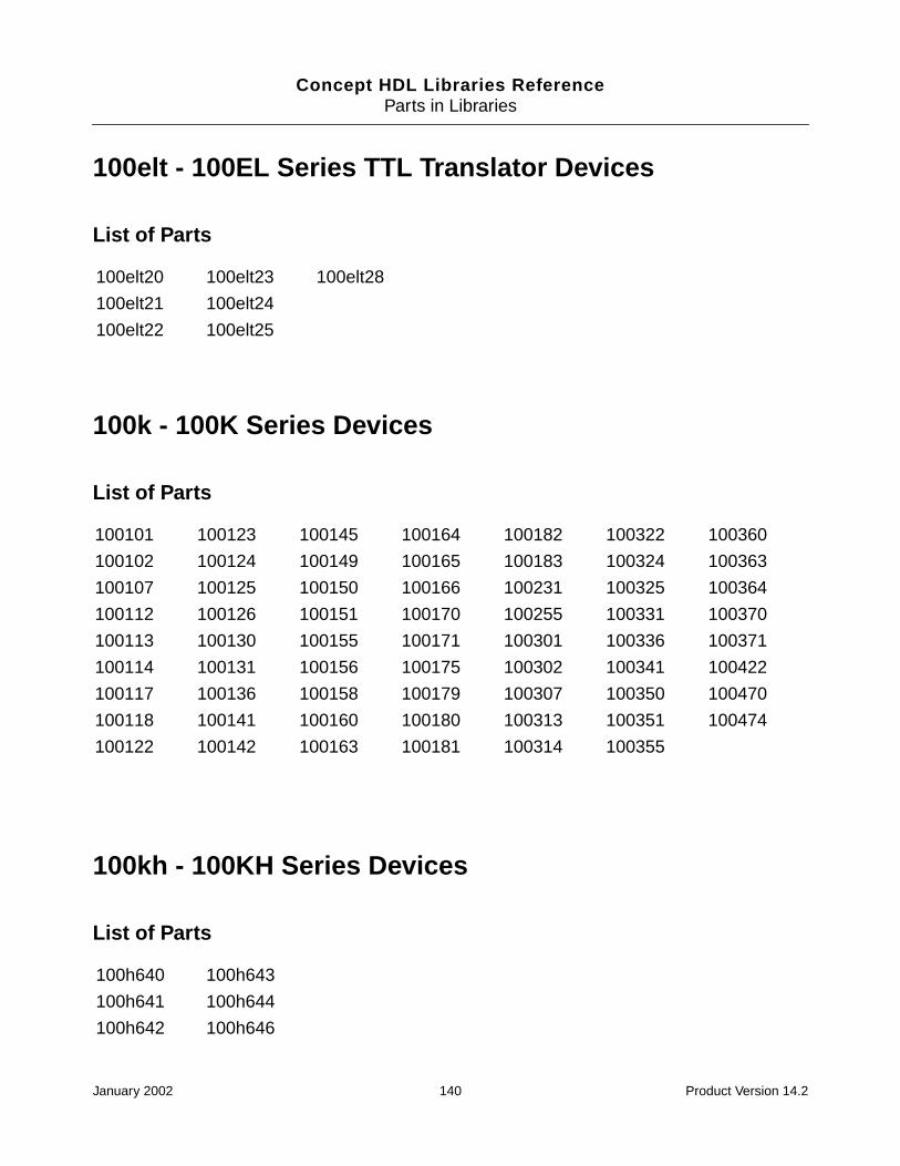
Concept HDL Libraries ReferenceParts in Libraries
100elt - 100EL Series TTL Translator Devices
List of Parts
100k - 100K Series Devices
List of Parts
100kh - 100KH Series Devices
List of Parts
100elt20 100elt23 100elt28
100elt21 100elt24
100elt22 100elt25
100101 100123 100145 100164 100182 100322 100360
100102 100124 100149 100165 100183 100324 100363
100107 100125 100150 100166 100231 100325 100364
100112 100126 100151 100170 100255 100331 100370
100113 100130 100155 100171 100301 100336 100371
100114 100131 100156 100175 100302 100341 100422
100117 100136 100158 100179 100307 100350 100470
100118 100141 100160 100180 100313 100351 100474
100122 100142 100163 100181 100314 100355
100h640 100h643
100h641 100h644
100h642 100h646
January 2002 140 Product Version 14.2
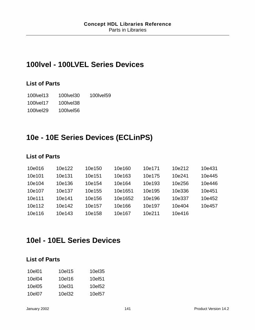
Concept HDL Libraries ReferenceParts in Libraries
100lvel - 100LVEL Series Devices
List of Parts
10e - 10E Series Devices (ECLinPS)
List of Parts
10el - 10EL Series Devices
List of Parts
100lvel13 100lvel30 100lvel59
100lvel17 100lvel38
100lvel29 100lvel56
10e016 10e122 10e150 10e160 10e171 10e212 10e431
10e101 10e131 10e151 10e163 10e175 10e241 10e445
10e104 10e136 10e154 10e164 10e193 10e256 10e446
10e107 10e137 10e155 10e1651 10e195 10e336 10e451
10e111 10e141 10e156 10e1652 10e196 10e337 10e452
10e112 10e142 10e157 10e166 10e197 10e404 10e457
10e116 10e143 10e158 10e167 10e211 10e416
10el01 10el15 10el35
10el04 10el16 10el51
10el05 10el31 10el52
10el07 10el32 10el57
January 2002 141 Product Version 14.2

Concept HDL Libraries ReferenceParts in Libraries
10elt - 10EL Series TTL Translator Devices
List of Parts
10k - 10K Series Devices
List of Parts
10el11 10el33 10el58
10el12 10el34 10el89
10elt20 10elt22 10elt25
10elt21 10elt24 10elt28
10016 10117 10138 10163 10186 10422b 10525
10100 10118 10139 10164 10188 10422c 10531
10101 10119 10141 10165 10189 10470a 10535
10102 10121 10144 10166 10190 10474a 10538
10103 10123 10145 10168 10191 10501 10562
10104 10124 10146 10170 10192 10502 10564
10105 10125 10147 10171 10193 10504 10586
10106 10128 10148 10172 10195 10505 10589
10107 10129 10149 10173 10197 10509 10598
10108 10130 10152 10174 10198 10513 10804
10109 10131 10153 10175 10210 10514 10805
10110 10132 10154 10176 10211 10515
10111 10133 10158 10178 10212 10516
10113 10134 10159 10179 10216 10517
10114 10135 10160 10180 10231 10521
10115 10136 10161 10181 10287 10523
January 2002 142 Product Version 14.2
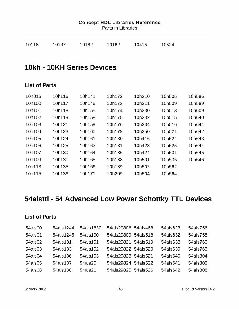
Concept HDL Libraries ReferenceParts in Libraries
10kh - 10KH Series Devices
List of Parts
54alsttl - 54 Advanced Low Power Schottky TTL Devices
List of Parts
10116 10137 10162 10182 10415 10524
10h016 10h116 10h141 10h172 10h210 10h505 10h586
10h100 10h117 10h145 10h173 10h211 10h509 10h589
10h101 10h118 10h155 10h174 10h330 10h513 10h609
10h102 10h119 10h158 10h175 10h332 10h515 10h640
10h103 10h121 10h159 10h176 10h334 10h516 10h641
10h104 10h123 10h160 10h179 10h350 10h521 10h642
10h105 10h124 10h161 10h180 10h416 10h524 10h643
10h106 10h125 10h162 10h181 10h423 10h525 10h644
10h107 10h130 10h164 10h186 10h424 10h531 10h645
10h109 10h131 10h165 10h188 10h501 10h535 10h646
10h113 10h135 10h166 10h189 10h502 10h562
10h115 10h136 10h171 10h209 10h504 10h564
54als00 54als1244 54als1832 54als29806 54als468 54als623 54als756
54als01 54als1245 54als190 54als29809 54als518 54als632 54als758
54als02 54als131 54als191 54als29821 54als519 54als638 54als760
54als03 54als133 54als192 54als29822 54als520 54als639 54als763
54als04 54als136 54als193 54als29823 54als521 54als640 54als804
54als05 54als137 54als20 54als29824 54als522 54als641 54als805
54als08 54als138 54als21 54als29825 54als526 54als642 54als808
January 2002 143 Product Version 14.2
Concept HDL Libraries ReferenceParts in Libraries
54asttl - 54 Advanced Schottky TTL Devices
List of Parts
54als09 54als139 54als22 54als29826 54als527 54als643 54als810
54als10 54als14 54als2240 54als299 54als528 54als644 54als811
54als1000 54als15 54als2242 54als30 54als533 54als645 54als832
54als1002 54als151 54als231 54als32 54als534 54als646 54als841
54als1003 54als153 54als236 54als323 54als538 54als647 54als842
54als1004 54als157 54als240 54als33 54als540 54als648 54als843
54als1005 54als158 54als241 54als34 54als541 54als649 54als844
54als1008 54als160 54als242 54als35 54als560 54als651 54als845
54als1010 54als161 54als243 54als352 54als561 54als652 54als846
54als1011 54als162 54als244 54als353 54als563 54als653 54als857
54als1020 54als163 54als245 54als365 54als564 54als654 54als86
54als1032 54als164 54als251 54als366 54als568 54als666 54als869
54als1034 54als1640 54als253 54als367 54als569 54als667 54als873
54als1035 54als1645 54als2540 54als368 54als573 54als677 54als874
54als109 54als165 54als2541 54als37 54als574 54als678 54als876
54als11 54als166 54als257 54als373 54als575 54als679 54als878
54als112 54als168 54als258 54als374 54als576 54als680 54als879
54als113 54als169 54als259 54als38 54als577 54als688 54als880a
54als114 54als174 54als27 54als40 54als580 54als689 54als963
54als12 54als175 54als273 54als465 54als620 54als74 54als964
54als1240 54als1805 54als28 54als466 54als621 54als746 54als996
54als1242 54als1808 54als280 54als467 54als622 54als747
54as00 54as153 54as231 54as30 54as638 54as808a 54as869
54as02 54as157 54as240 54as32 54as639 54as810 54as870
54as04 54as158 54as241 54as323 54as640 54as811 54as871
54as08 54as160 54as242 54as3374 54as641 54as821 54as873
54as10 54as161 54as243 54as34 54as642 54as822 54as874
January 2002 144 Product Version 14.2
Concept HDL Libraries ReferenceParts in Libraries
54fact - 54 FAST Advanced CMOS TTL Devices
List of Parts
54as1000 54as162 54as244 54as352 54as643 54as823 54as876
54as1004 54as163 54as245 54as353 54as644 54as824 54as877
54as1008 54as168 54as251 54as373 54as645 54as825 54as878
54as1032 54as169 54as253 54as374 54as646 54as826 54as879
54as1034 54as174 54as257 54as533 54as648 54as832a 54as880
54as1036 54as175 54as258 54as534 54as651 54as841 54as881
54as109 54as1804 54as2620 54as573 54as652 54as842 54as882
54as11 54as1805 54as2623 54as574 54as74 54as843 54as8838
54as112 54as1808 54as264 54as575 54as756 54as844 54as885
54as113 54as181 54as2640 54as576 54as757 54as845 54as888
54as114 54as182 54as2645 54as577 54as758 54as846 54as890
54as131 54as1832 54as27 54as580 54as759 54as852 54as897
54as136 54as194 54as280 54as620 54as760 54as856 54as95
54as137 54as195 54as282 54as621 54as762 54as857
54as138 54as20 54as286 54as622 54as763 54as86
54as139 54as21 54as298 54as623 54as804a 54as866
54as151 54as230 54as299 54as632 54as805a 54as867
54ac00 54ac175 54ac373 54ac7060 54act151 54act257 54act646
54ac02 54ac191 54ac374 54ac7061 54act153 54act258 54act647
54ac04 54ac193 54ac533 54ac74 54act157 54act273 54act648
54ac05 54ac20 54ac534 54ac7623 54act158 54act280 54act649
54ac08 54ac238 54ac540 54ac821 54act161 54act283 54act651
54ac10 54ac240 54ac541 54ac86 54act163 54act299 54act652
54ac109 54ac241 54ac563 54act00 54act164 54act32 54act653
54ac112 54ac244 54ac564 54act02 54act174 54act323 54act654
54ac138 54ac245 54ac573 54act04 54act175 54act373 54act7060
54ac139 54ac251 54ac574 54act05 54act191 54act374 54act7061
January 2002 145 Product Version 14.2
Concept HDL Libraries ReferenceParts in Libraries
54fast - 54 FAST TTL Devices
List of Parts
54ac14 54ac253 54ac623 54act08 54act193 54act533 54act74
54ac151 54ac257 54ac646 54act10 54act20 54act534 54act7623
54ac153 54ac258 54ac647 54act109 54act238 54act540 54act821
54ac157 54ac273 54ac648 54act112 54act240 54act541 54act86
54ac158 54ac280 54ac649 54act11253 54act241 54act563
54ac161 54ac283 54ac651 54act11353 54act244 54act564
54ac163 54ac299 54ac652 54act138 54act245 54act573
54ac164 54ac32 54ac653 54act139 54act251 54act574
54ac174 54ac323 54ac654 54act14 54act253 54act623
54f00 54f153 54f194 54f280 54f377 54f540 54f646
54f02 54f157 54f198 54f283 54f378 54f541 54f648
54f04 54f158 54f20 54f298 54f379 54f543 54f652
54f08 54f160 54f21 54f299 54f38 54f544 54f655
54f09 54f161 54f219 54f30 54f381 54f545 54f656a
54f10 54f162 54f240 54f3037 54f382 54f547 54f657
54f109 54f163 54f241 54f32 54f385 54f548 54f676
54f11 54f164 54f242 54f322 54f395 54f563 54f74
54f112 54f168 54f243 54f323 54f398 54f564 54f779
54f113 54f169 54f244 54f350 54f399 54f568 54f803
54f114 54f173 54f245 54f352 54f40 54f569 54f821
54f125 54f174 54f251 54f353 54f412 54f573 54f823
54f126 54f175 54f253 54f36 54f51 54f574 54f825
54f13 54f181 54f256 54f365 54f518 54f579 54f827
54f132 54f182 54f257 54f366 54f519 54f583 54f828
54f138 54f189 54f258 54f367 54f520 54f620 54f841
54f139 54f190 54f259 54f368 54f521 54f621 54f85
54f14 54f191 54f269 54f37 54f533 54f622 54f86
January 2002 146 Product Version 14.2

Concept HDL Libraries ReferenceParts in Libraries
54fct - 54 FAST CMOS TTL Devices
List of Parts
54hcmos - 54 High Speed CMOS Devices
List of Parts
54f148 54f192 54f27 54f373 54f534 54f623
54f151 54f193 54f273 54f374 54f538 54f64
54fct138 54fct191 54fct245 54fct377 54fct573 54fct821
54fct139 54fct193 54fct273 54fct521 54fct574 54fct823
54fct161 54fct240 54fct299 54fct533 54fct646 54fct827
54fct163 54fct241 54fct373 54fct534 54fct648 54fct841
54fct182 54fct244 54fct374 54fct543 54fct652 54fct864
54hc00 54hc163 54hc280 54hc4050 54hc643 54hct157 54hct30
54hc01 54hc164 54hc283 54hc4051 54hc645 54hct158 54hct32
54hc02 54hc165 54hc292 54hc4052 54hc646 54hct160 54hct356
54hc03 54hc166 54hc294 54hc4053 54hc648 54hct161 54hct373
54hc04 54hc173 54hc297 54hc4060 54hc651 54hct162 54hct374
54hc05 54hc174 54hc298 54hc4066 54hc652 54hct163 54hct377
54hc08 54hc175 54hc299 54hc4075 54hc688 54hct164 54hct393
54hc09 54hc180 54hc30 54hc4078 54hc7266 54hct165 54hct40103
54hc10 54hc181 54hc32 54hc42 54hc73 54hct166 54hct4020
54hc107 54hc182 54hc353 54hc423 54hc74 54hct174 54hct4040
54hc109 54hc190 54hc354 54hc4316 54hc75 54hct175 54hct423
54hc11 54hc191 54hc356 54hc4351 54hc76 54hct182 54hct4538
54hc112 54hc192 54hc36 54hc4352 54hc805 54hct190 54hct533
January 2002 147 Product Version 14.2
Concept HDL Libraries ReferenceParts in Libraries
54lsttl - 54 Low Power Schottky TTL Devices
List of Parts
54hc113 54hc193 54hc365 54hc4353 54hc808 54hct191 54hct534
54hc114 54hc194 54hc366 54hc4511 54hc832 54hct192 54hct540
54hc123 54hc195 54hc367 54hc4514 54hc85 54hct193 54hct541
54hc125 54hc20 54hc368 54hc4538 54hc86 54hct194 54hct563
54hc126 54hc21 54hc373 54hc4543 54hct00 54hct20 54hct564
54hc132 54hc221 54hc374 54hc490 54hct02 54hct21 54hct573
54hc133 54hc237 54hc375 54hc51 54hct03 54hct221 54hct574
54hc137 54hc238 54hc377 54hc533 54hct04 54hct238 54hct640
54hc138 54hc240 54hc378 54hc534 54hct08 54hct240 54hct643
54hc139 54hc241 54hc379 54hc540 54hct10 54hct241 54hct648
54hc14 54hc242 54hc381 54hc541 54hct109 54hct244 54hct670
54hc147 54hc243 54hc386 54hc563 54hct11 54hct245 54hct688
54hc148 54hc244 54hc390 54hc564 54hct112 54hct251 54hct74
54hc151 54hc245 54hc393 54hc573 54hct123 54hct253 54hct85
54hc152 54hc251 54hc4002 54hc574 54hct125 54hct257 54hct86
54hc153 54hc253 54hc40103 54hc58 54hct126 54hct258 54hcu04
54hc154 54hc257 54hc4016 54hc590 54hct138 54hct27
54hc157 54hc258 54hc4017 54hc595 54hct139 54hct273
54hc158 54hc259 54hc4020 54hc597 54hct14 54hct280
54hc160 54hc266 54hc4024 54hc620 54hct147 54hct283
54hc161 54hc27 54hc4040 54hc623 54hct151 54hct297
54hc162 54hc273 54hc4049 54hc640 54hct153 54hct299
54ls00 54ls154 54ls224 54ls31 54ls396 54ls598 54ls670
54ls01 54ls155 54ls227 54ls32 54ls398 54ls604 54ls671
54ls02 54ls156 54ls228 54ls321 54ls399 54ls605 54ls672
54ls03 54ls157 54ls24 54ls322 54ls40 54ls606 54ls674
54ls04 54ls158 54ls240 54ls323 54ls42 54ls607 54ls682
January 2002 148 Product Version 14.2
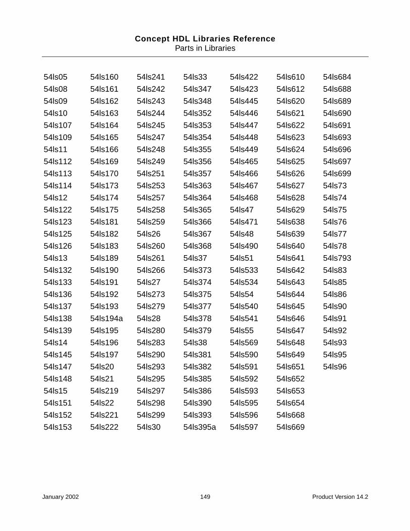
Concept HDL Libraries ReferenceParts in Libraries
54ls05 54ls160 54ls241 54ls33 54ls422 54ls610 54ls684
54ls08 54ls161 54ls242 54ls347 54ls423 54ls612 54ls688
54ls09 54ls162 54ls243 54ls348 54ls445 54ls620 54ls689
54ls10 54ls163 54ls244 54ls352 54ls446 54ls621 54ls690
54ls107 54ls164 54ls245 54ls353 54ls447 54ls622 54ls691
54ls109 54ls165 54ls247 54ls354 54ls448 54ls623 54ls693
54ls11 54ls166 54ls248 54ls355 54ls449 54ls624 54ls696
54ls112 54ls169 54ls249 54ls356 54ls465 54ls625 54ls697
54ls113 54ls170 54ls251 54ls357 54ls466 54ls626 54ls699
54ls114 54ls173 54ls253 54ls363 54ls467 54ls627 54ls73
54ls12 54ls174 54ls257 54ls364 54ls468 54ls628 54ls74
54ls122 54ls175 54ls258 54ls365 54ls47 54ls629 54ls75
54ls123 54ls181 54ls259 54ls366 54ls471 54ls638 54ls76
54ls125 54ls182 54ls26 54ls367 54ls48 54ls639 54ls77
54ls126 54ls183 54ls260 54ls368 54ls490 54ls640 54ls78
54ls13 54ls189 54ls261 54ls37 54ls51 54ls641 54ls793
54ls132 54ls190 54ls266 54ls373 54ls533 54ls642 54ls83
54ls133 54ls191 54ls27 54ls374 54ls534 54ls643 54ls85
54ls136 54ls192 54ls273 54ls375 54ls54 54ls644 54ls86
54ls137 54ls193 54ls279 54ls377 54ls540 54ls645 54ls90
54ls138 54ls194a 54ls28 54ls378 54ls541 54ls646 54ls91
54ls139 54ls195 54ls280 54ls379 54ls55 54ls647 54ls92
54ls14 54ls196 54ls283 54ls38 54ls569 54ls648 54ls93
54ls145 54ls197 54ls290 54ls381 54ls590 54ls649 54ls95
54ls147 54ls20 54ls293 54ls382 54ls591 54ls651 54ls96
54ls148 54ls21 54ls295 54ls385 54ls592 54ls652
54ls15 54ls219 54ls297 54ls386 54ls593 54ls653
54ls151 54ls22 54ls298 54ls390 54ls595 54ls654
54ls152 54ls221 54ls299 54ls393 54ls596 54ls668
54ls153 54ls222 54ls30 54ls395a 54ls597 54ls669
January 2002 149 Product Version 14.2
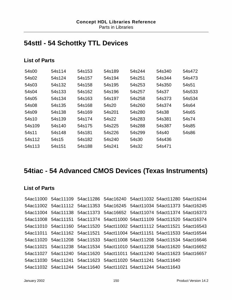
Concept HDL Libraries ReferenceParts in Libraries
54sttl - 54 Schottky TTL Devices
List of Parts
54tiac - 54 Advanced CMOS Devices (Texas Instruments)
List of Parts
54s00 54s114 54s153 54s189 54s244 54s340 54s472
54s02 54s124 54s157 54s194 54s251 54s344 54s473
54s03 54s132 54s158 54s195 54s253 54s350 54s51
54s04 54s133 54s162 54s196 54s257 54s37 54s533
54s05 54s134 54s163 54s197 54s258 54s373 54s534
54s08 54s135 54s168 54s20 54s260 54s374 54s64
54s09 54s138 54s169 54s201 54s280 54s38 54s65
54s10 54s139 54s174 54s22 54s283 54s381 54s74
54s109 54s140 54s175 54s225 54s288 54s387 54s85
54s11 54s148 54s181 54s226 54s299 54s40 54s86
54s112 54s15 54s182 54s240 54s30 54s436
54s113 54s151 54s188 54s241 54s32 54s471
54ac11000 54ac11109 54ac11286 54ac16240 54act11032 54act11280 54act16244
54ac11002 54ac11112 54ac11353 54ac16245 54act11034 54act11373 54act16245
54ac11004 54ac11138 54ac11373 54ac16652 54act11074 54act11374 54act16373
54ac11008 54ac11151 54ac11374 54act11000 54act11109 54act11520 54act16374
54ac11010 54ac11160 54ac11520 54act11002 54act11112 54act11521 54act16543
54ac11011 54ac11162 54ac11521 54act11004 54act11151 54act11533 54act16544
54ac11020 54ac11208 54ac11533 54act11008 54act11208 54act11534 54act16646
54ac11021 54ac11238 54ac11534 54act11010 54act11238 54act11620 54act16652
54ac11027 54ac11240 54ac11620 54act11011 54act11240 54act11623 54act16657
54ac11030 54ac11241 54ac11623 54act11020 54act11241 54act11640
54ac11032 54ac11244 54ac11640 54act11021 54act11244 54act11643
January 2002 150 Product Version 14.2
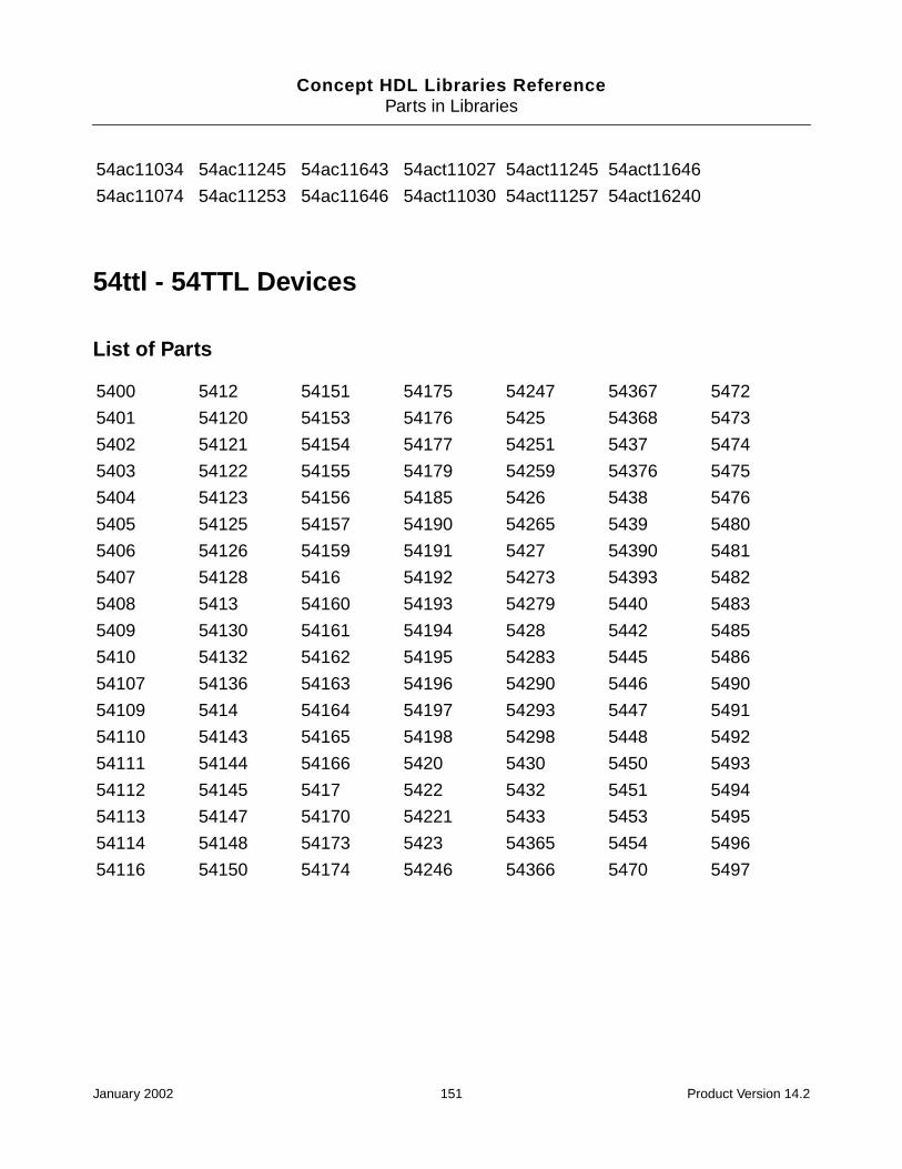
Concept HDL Libraries ReferenceParts in Libraries
54ttl - 54TTL Devices
List of Parts
54ac11034 54ac11245 54ac11643 54act11027 54act11245 54act11646
54ac11074 54ac11253 54ac11646 54act11030 54act11257 54act16240
5400 5412 54151 54175 54247 54367 5472
5401 54120 54153 54176 5425 54368 5473
5402 54121 54154 54177 54251 5437 5474
5403 54122 54155 54179 54259 54376 5475
5404 54123 54156 54185 5426 5438 5476
5405 54125 54157 54190 54265 5439 5480
5406 54126 54159 54191 5427 54390 5481
5407 54128 5416 54192 54273 54393 5482
5408 5413 54160 54193 54279 5440 5483
5409 54130 54161 54194 5428 5442 5485
5410 54132 54162 54195 54283 5445 5486
54107 54136 54163 54196 54290 5446 5490
54109 5414 54164 54197 54293 5447 5491
54110 54143 54165 54198 54298 5448 5492
54111 54144 54166 5420 5430 5450 5493
54112 54145 5417 5422 5432 5451 5494
54113 54147 54170 54221 5433 5453 5495
54114 54148 54173 5423 54365 5454 5496
54116 54150 54174 54246 54366 5470 5497
January 2002 151 Product Version 14.2
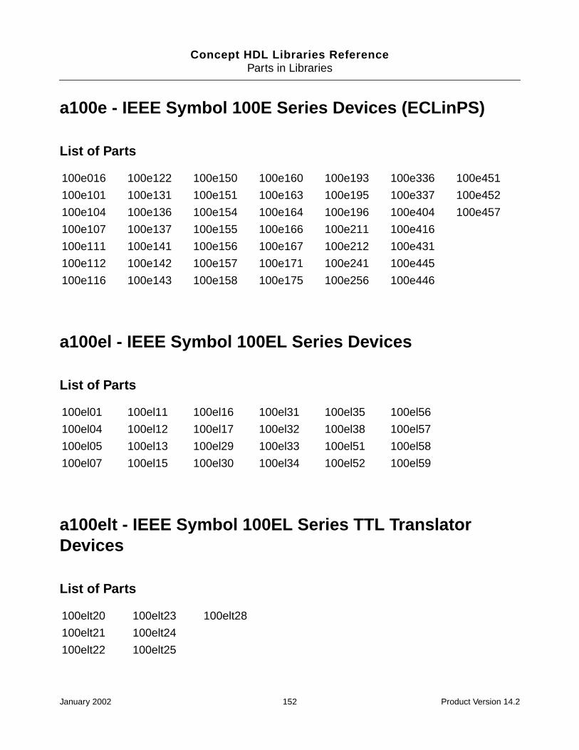
Concept HDL Libraries ReferenceParts in Libraries
a100e - IEEE Symbol 100E Series Devices (ECLinPS)
List of Parts
a100el - IEEE Symbol 100EL Series Devices
List of Parts
a100elt - IEEE Symbol 100EL Series TTL TranslatorDevices
List of Parts
100e016 100e122 100e150 100e160 100e193 100e336 100e451
100e101 100e131 100e151 100e163 100e195 100e337 100e452
100e104 100e136 100e154 100e164 100e196 100e404 100e457
100e107 100e137 100e155 100e166 100e211 100e416
100e111 100e141 100e156 100e167 100e212 100e431
100e112 100e142 100e157 100e171 100e241 100e445
100e116 100e143 100e158 100e175 100e256 100e446
100el01 100el11 100el16 100el31 100el35 100el56
100el04 100el12 100el17 100el32 100el38 100el57
100el05 100el13 100el29 100el33 100el51 100el58
100el07 100el15 100el30 100el34 100el52 100el59
100elt20 100elt23 100elt28
100elt21 100elt24
100elt22 100elt25
January 2002 152 Product Version 14.2

Concept HDL Libraries ReferenceParts in Libraries
a100k - IEEE Symbol 100K Series Devices
List of Parts
a100kh - IEEE Symbol 100KH Series Devices
List of Parts
a100lvel - IEEE Symbol 100LVEL Series Devices
List of Parts
100101 100123 100145 100164 100182 100322 100360
100102 100124 100149 100165 100183 100324 100363
100107 100125 100150 100166 100231 100325 100364
100112 100126 100151 100170 100255 100331 100370
100113 100130 100155 100171 100301 100336 100371
100114 100131 100156 100175 100302 100341 100422
100117 100136 100158 100179 100307 100350 100470
100118 100141 100160 100180 100313 100351 100474
100122 100142 100163 100181 100314 100355
100h640 100h642 100h644
100h641 100h643 100h646
100lvel13 100lvel29 100lvel38
100lvel17 100lvel30 100lvel56
January 2002 153 Product Version 14.2
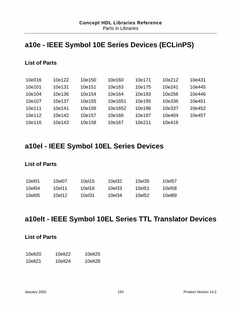
Concept HDL Libraries ReferenceParts in Libraries
a10e - IEEE Symbol 10E Series Devices (ECLinPS)
List of Parts
a10el - IEEE Symbol 10EL Series Devices
List of Parts
a10elt - IEEE Symbol 10EL Series TTL Translator Devices
List of Parts
10e016 10e122 10e150 10e160 10e171 10e212 10e431
10e101 10e131 10e151 10e163 10e175 10e241 10e445
10e104 10e136 10e154 10e164 10e193 10e256 10e446
10e107 10e137 10e155 10e1651 10e195 10e336 10e451
10e111 10e141 10e156 10e1652 10e196 10e337 10e452
10e112 10e142 10e157 10e166 10e197 10e404 10e457
10e116 10e143 10e158 10e167 10e211 10e416
10el01 10el07 10el15 10el32 10el35 10el57
10el04 10el11 10el16 10el33 10el51 10el58
10el05 10el12 10el31 10el34 10el52 10el89
10elt20 10elt22 10elt25
10elt21 10elt24 10elt28
January 2002 154 Product Version 14.2

Concept HDL Libraries ReferenceParts in Libraries
a10k - IEEE Symbol 10K Series Devices
List of Parts
a10kh - IEEE Symbol 10KH Series Devices
List of Parts
10100 10117 10137 10161 10180 10287 10521
10101 10118 10138 10162 10181 10415 10523
10102 10119 10139 10163 10182 10422b 10524
10103 10121 10141 10164 10186 10422c 10525
10104 10123 10144 10165 10188 10470a 10531
10105 10124 10145 10166 10189 10474a 10535
10106 10125 10146 10168 10190 10501 10538
10107 10128 10147 10170 10191 10502 10562
10108 10129 10148 10171 10192 10504 10564
10109 10130 10149 10172 10195 10505 10586
10110 10131 10152 10173 10197 10509 10598
10111 10132 10153 10174 10210 10513
10113 10133 10154 10175 10211 10514
10114 10134 10158 10176 10212 10515
10115 10135 10159 10178 10216 10516
10116 10136 10160 10179 10231 10517
10h016 10h116 10h141 10h172 10h210 10h505 10h586
10h100 10h117 10h145 10h173 10h211 10h509 10h589
10h101 10h118 10h155 10h174 10h330 10h513 10h609
10h102 10h119 10h158 10h175 10h332 10h515 10h640
10h103 10h121 10h159 10h176 10h334 10h516 10h641
January 2002 155 Product Version 14.2
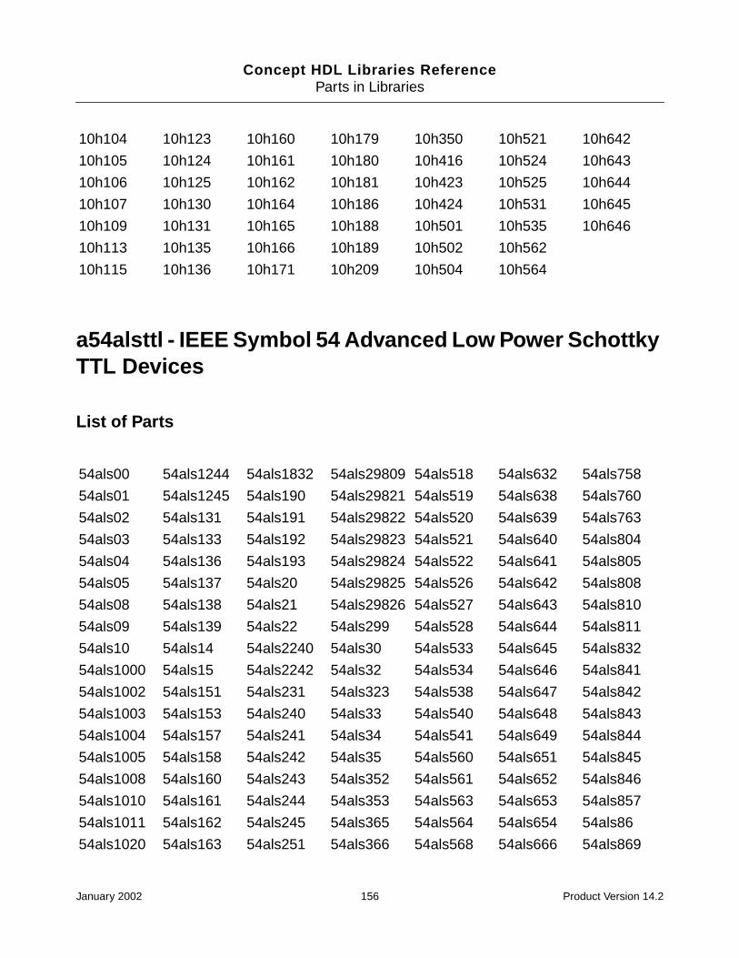
Concept HDL Libraries ReferenceParts in Libraries
a54alsttl - IEEE Symbol 54 Advanced Low Power SchottkyTTL Devices
List of Parts
10h104 10h123 10h160 10h179 10h350 10h521 10h642
10h105 10h124 10h161 10h180 10h416 10h524 10h643
10h106 10h125 10h162 10h181 10h423 10h525 10h644
10h107 10h130 10h164 10h186 10h424 10h531 10h645
10h109 10h131 10h165 10h188 10h501 10h535 10h646
10h113 10h135 10h166 10h189 10h502 10h562
10h115 10h136 10h171 10h209 10h504 10h564
54als00 54als1244 54als1832 54als29809 54als518 54als632 54als758
54als01 54als1245 54als190 54als29821 54als519 54als638 54als760
54als02 54als131 54als191 54als29822 54als520 54als639 54als763
54als03 54als133 54als192 54als29823 54als521 54als640 54als804
54als04 54als136 54als193 54als29824 54als522 54als641 54als805
54als05 54als137 54als20 54als29825 54als526 54als642 54als808
54als08 54als138 54als21 54als29826 54als527 54als643 54als810
54als09 54als139 54als22 54als299 54als528 54als644 54als811
54als10 54als14 54als2240 54als30 54als533 54als645 54als832
54als1000 54als15 54als2242 54als32 54als534 54als646 54als841
54als1002 54als151 54als231 54als323 54als538 54als647 54als842
54als1003 54als153 54als240 54als33 54als540 54als648 54als843
54als1004 54als157 54als241 54als34 54als541 54als649 54als844
54als1005 54als158 54als242 54als35 54als560 54als651 54als845
54als1008 54als160 54als243 54als352 54als561 54als652 54als846
54als1010 54als161 54als244 54als353 54als563 54als653 54als857
54als1011 54als162 54als245 54als365 54als564 54als654 54als86
54als1020 54als163 54als251 54als366 54als568 54als666 54als869
January 2002 156 Product Version 14.2
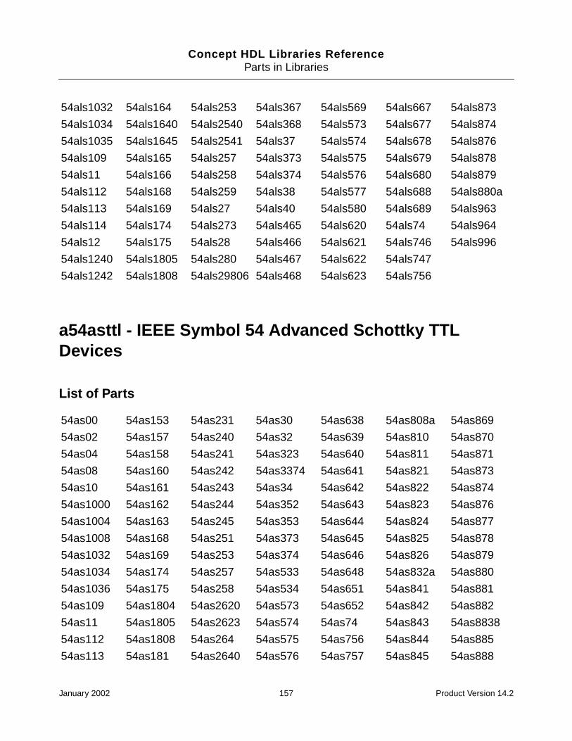
Concept HDL Libraries ReferenceParts in Libraries
a54asttl - IEEE Symbol 54 Advanced Schottky TTLDevices
List of Parts
54als1032 54als164 54als253 54als367 54als569 54als667 54als873
54als1034 54als1640 54als2540 54als368 54als573 54als677 54als874
54als1035 54als1645 54als2541 54als37 54als574 54als678 54als876
54als109 54als165 54als257 54als373 54als575 54als679 54als878
54als11 54als166 54als258 54als374 54als576 54als680 54als879
54als112 54als168 54als259 54als38 54als577 54als688 54als880a
54als113 54als169 54als27 54als40 54als580 54als689 54als963
54als114 54als174 54als273 54als465 54als620 54als74 54als964
54als12 54als175 54als28 54als466 54als621 54als746 54als996
54als1240 54als1805 54als280 54als467 54als622 54als747
54als1242 54als1808 54als29806 54als468 54als623 54als756
54as00 54as153 54as231 54as30 54as638 54as808a 54as869
54as02 54as157 54as240 54as32 54as639 54as810 54as870
54as04 54as158 54as241 54as323 54as640 54as811 54as871
54as08 54as160 54as242 54as3374 54as641 54as821 54as873
54as10 54as161 54as243 54as34 54as642 54as822 54as874
54as1000 54as162 54as244 54as352 54as643 54as823 54as876
54as1004 54as163 54as245 54as353 54as644 54as824 54as877
54as1008 54as168 54as251 54as373 54as645 54as825 54as878
54as1032 54as169 54as253 54as374 54as646 54as826 54as879
54as1034 54as174 54as257 54as533 54as648 54as832a 54as880
54as1036 54as175 54as258 54as534 54as651 54as841 54as881
54as109 54as1804 54as2620 54as573 54as652 54as842 54as882
54as11 54as1805 54as2623 54as574 54as74 54as843 54as8838
54as112 54as1808 54as264 54as575 54as756 54as844 54as885
54as113 54as181 54as2640 54as576 54as757 54as845 54as888
January 2002 157 Product Version 14.2

Concept HDL Libraries ReferenceParts in Libraries
a54fact - IEEE Symbol 54 FAST Advanced CMOS TTLDevices
List of Parts
54as114 54as182 54as2645 54as577 54as758 54as846 54as890
54as131 54as1832 54as27 54as580 54as759 54as852 54as897
54as136 54as194 54as280 54as620 54as760 54as856 54as95
54as137 54as195 54as282 54as621 54as762 54as857
54as138 54as20 54as286 54as622 54as763 54as86
54as139 54as21 54as298 54as623 54as804a 54as866
54as151 54as230 54as299 54as632 54as805a 54as867
54ac00 54ac175 54ac373 54ac7060 54act151 54act257 54act64654ac02 54ac191 54ac374 54ac7061 54act153 54act258 54act64754ac04 54ac193 54ac533 54ac74 54act157 54act273 54act64854ac05 54ac20 54ac534 54ac7623 54act158 54act280 54act64954ac08 54ac238 54ac540 54ac821 54act161 54act283 54act65154ac10 54ac240 54ac541 54ac86 54act163 54act299 54act65254ac109 54ac241 54ac563 54act00 54act164 54act32 54act65354ac112 54ac244 54ac564 54act02 54act174 54act323 54act65454ac138 54ac245 54ac573 54act04 54act175 54act373 54act706054ac139 54ac251 54ac574 54act05 54act191 54act374 54act706154ac14 54ac253 54ac623 54act08 54act193 54act533 54act7454ac151 54ac257 54ac646 54act10 54act20 54act534 54act762354ac153 54ac258 54ac647 54act109 54act238 54act540 54act82154ac157 54ac273 54ac648 54act112 54act240 54act541 54act8654ac158 54ac280 54ac649 54act11253 54act241 54act56354ac161 54ac283 54ac651 54act11353 54act244 54act56454ac163 54ac299 54ac652 54act138 54act245 54act57354ac164 54ac32 54ac653 54act139 54act251 54act57454ac174 54ac323 54ac654 54act14 54act253 54act623
January 2002 158 Product Version 14.2

Concept HDL Libraries ReferenceParts in Libraries
a54fast - IEEE Symbol 54 FAST TTL Devices
List of Parts
a54fct - IEEE Symbol 54 FAST CMOS TTL Devices
List of Parts
54f00 54f153 54f194 54f280 54f377 54f540 54f646
54f02 54f157 54f198 54f283 54f378 54f541 54f648
54f04 54f158 54f20 54f298 54f379 54f543 54f652
54f08 54f160 54f21 54f299 54f38 54f544 54f655
54f09 54f161 54f219 54f30 54f381 54f545 54f656a
54f10 54f162 54f240 54f3037 54f382 54f547 54f657
54f109 54f163 54f241 54f32 54f385 54f548 54f676
54f11 54f164 54f242 54f322 54f395 54f563 54f74
54f112 54f168 54f243 54f323 54f398 54f564 54f779
54f113 54f169 54f244 54f350 54f399 54f568 54f803
54f114 54f173 54f245 54f352 54f40 54f569 54f821
54f125 54f174 54f251 54f353 54f412 54f573 54f823
54f126 54f175 54f253 54f36 54f51 54f574 54f825
54f13 54f181 54f256 54f365 54f518 54f579 54f827
54f132 54f182 54f257 54f366 54f519 54f583 54f828
54f138 54f189 54f258 54f367 54f520 54f620 54f841
54f139 54f190 54f259 54f368 54f521 54f621 54f85
54f14 54f191 54f269 54f37 54f533 54f622 54f86
54f148 54f192 54f27 54f373 54f534 54f623
54f151 54f193 54f273 54f374 54f538 54f64
54fct138 54fct191 54fct245 54fct377 54fct573 54fct821
January 2002 159 Product Version 14.2

Concept HDL Libraries ReferenceParts in Libraries
a54hcmos - IEEE Symbol 54 High Speed CMOS Devices
List of Parts
54fct139 54fct193 54fct273 54fct521 54fct574 54fct823
54fct161 54fct240 54fct299 54fct533 54fct646 54fct827
54fct163 54fct241 54fct373 54fct534 54fct648 54fct841
54fct182 54fct244 54fct374 54fct543 54fct652 54fct864
54hc00 54hc163 54hc280 54hc4050 54hc643 54hct157 54hct30
54hc01 54hc164 54hc283 54hc4051 54hc645 54hct158 54hct32
54hc02 54hc165 54hc292 54hc4052 54hc646 54hct160 54hct356
54hc03 54hc166 54hc294 54hc4053 54hc648 54hct161 54hct373
54hc04 54hc173 54hc297 54hc4060 54hc651 54hct162 54hct374
54hc05 54hc174 54hc298 54hc4066 54hc652 54hct163 54hct377
54hc08 54hc175 54hc299 54hc4075 54hc688 54hct164 54hct393
54hc09 54hc180 54hc30 54hc4078 54hc7266 54hct165 54hct40103
54hc10 54hc181 54hc32 54hc42 54hc73 54hct166 54hct4020
54hc107 54hc182 54hc353 54hc423 54hc74 54hct174 54hct4040
54hc109 54hc190 54hc354 54hc4316 54hc75 54hct175 54hct423
54hc11 54hc191 54hc356 54hc4351 54hc76 54hct182 54hct4538
54hc112 54hc192 54hc36 54hc4352 54hc805 54hct190 54hct533
54hc113 54hc193 54hc365 54hc4353 54hc808 54hct191 54hct534
54hc114 54hc194 54hc366 54hc4511 54hc832 54hct192 54hct540
54hc123 54hc195 54hc367 54hc4514 54hc85 54hct193 54hct541
54hc125 54hc20 54hc368 54hc4538 54hc86 54hct194 54hct563
54hc126 54hc21 54hc373 54hc4543 54hct00 54hct20 54hct564
54hc132 54hc221 54hc374 54hc490 54hct02 54hct21 54hct573
54hc133 54hc237 54hc375 54hc51 54hct03 54hct221 54hct574
54hc137 54hc238 54hc377 54hc533 54hct04 54hct238 54hct640
54hc138 54hc240 54hc378 54hc534 54hct08 54hct240 54hct643
January 2002 160 Product Version 14.2
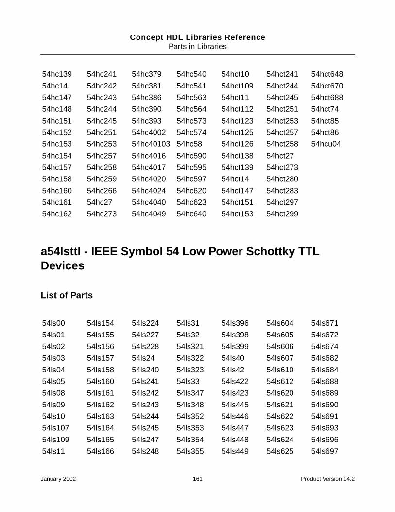
Concept HDL Libraries ReferenceParts in Libraries
a54lsttl - IEEE Symbol 54 Low Power Schottky TTLDevices
List of Parts
54hc139 54hc241 54hc379 54hc540 54hct10 54hct241 54hct648
54hc14 54hc242 54hc381 54hc541 54hct109 54hct244 54hct670
54hc147 54hc243 54hc386 54hc563 54hct11 54hct245 54hct688
54hc148 54hc244 54hc390 54hc564 54hct112 54hct251 54hct74
54hc151 54hc245 54hc393 54hc573 54hct123 54hct253 54hct85
54hc152 54hc251 54hc4002 54hc574 54hct125 54hct257 54hct86
54hc153 54hc253 54hc40103 54hc58 54hct126 54hct258 54hcu04
54hc154 54hc257 54hc4016 54hc590 54hct138 54hct27
54hc157 54hc258 54hc4017 54hc595 54hct139 54hct273
54hc158 54hc259 54hc4020 54hc597 54hct14 54hct280
54hc160 54hc266 54hc4024 54hc620 54hct147 54hct283
54hc161 54hc27 54hc4040 54hc623 54hct151 54hct297
54hc162 54hc273 54hc4049 54hc640 54hct153 54hct299
54ls00 54ls154 54ls224 54ls31 54ls396 54ls604 54ls671
54ls01 54ls155 54ls227 54ls32 54ls398 54ls605 54ls672
54ls02 54ls156 54ls228 54ls321 54ls399 54ls606 54ls674
54ls03 54ls157 54ls24 54ls322 54ls40 54ls607 54ls682
54ls04 54ls158 54ls240 54ls323 54ls42 54ls610 54ls684
54ls05 54ls160 54ls241 54ls33 54ls422 54ls612 54ls688
54ls08 54ls161 54ls242 54ls347 54ls423 54ls620 54ls689
54ls09 54ls162 54ls243 54ls348 54ls445 54ls621 54ls690
54ls10 54ls163 54ls244 54ls352 54ls446 54ls622 54ls691
54ls107 54ls164 54ls245 54ls353 54ls447 54ls623 54ls693
54ls109 54ls165 54ls247 54ls354 54ls448 54ls624 54ls696
54ls11 54ls166 54ls248 54ls355 54ls449 54ls625 54ls697
January 2002 161 Product Version 14.2
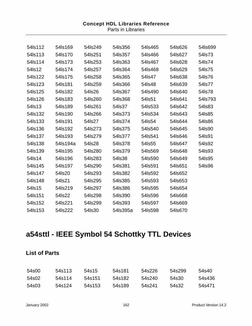
Concept HDL Libraries ReferenceParts in Libraries
a54sttl - IEEE Symbol 54 Schottky TTL Devices
List of Parts
54ls112 54ls169 54ls249 54ls356 54ls465 54ls626 54ls699
54ls113 54ls170 54ls251 54ls357 54ls466 54ls627 54ls73
54ls114 54ls173 54ls253 54ls363 54ls467 54ls628 54ls74
54ls12 54ls174 54ls257 54ls364 54ls468 54ls629 54ls75
54ls122 54ls175 54ls258 54ls365 54ls47 54ls638 54ls76
54ls123 54ls181 54ls259 54ls366 54ls48 54ls639 54ls77
54ls125 54ls182 54ls26 54ls367 54ls490 54ls640 54ls78
54ls126 54ls183 54ls260 54ls368 54ls51 54ls641 54ls793
54ls13 54ls189 54ls261 54ls37 54ls533 54ls642 54ls83
54ls132 54ls190 54ls266 54ls373 54ls534 54ls643 54ls85
54ls133 54ls191 54ls27 54ls374 54ls54 54ls644 54ls86
54ls136 54ls192 54ls273 54ls375 54ls540 54ls645 54ls90
54ls137 54ls193 54ls279 54ls377 54ls541 54ls646 54ls91
54ls138 54ls194a 54ls28 54ls378 54ls55 54ls647 54ls92
54ls139 54ls195 54ls280 54ls379 54ls569 54ls648 54ls93
54ls14 54ls196 54ls283 54ls38 54ls590 54ls649 54ls95
54ls145 54ls197 54ls290 54ls381 54ls591 54ls651 54ls96
54ls147 54ls20 54ls293 54ls382 54ls592 54ls652
54ls148 54ls21 54ls295 54ls385 54ls593 54ls653
54ls15 54ls219 54ls297 54ls386 54ls595 54ls654
54ls151 54ls22 54ls298 54ls390 54ls596 54ls668
54ls152 54ls221 54ls299 54ls393 54ls597 54ls669
54ls153 54ls222 54ls30 54ls395a 54ls598 54ls670
54s00 54s113 54s15 54s181 54s226 54s299 54s40
54s02 54s114 54s151 54s182 54s240 54s30 54s436
54s03 54s124 54s153 54s189 54s241 54s32 54s471
January 2002 162 Product Version 14.2
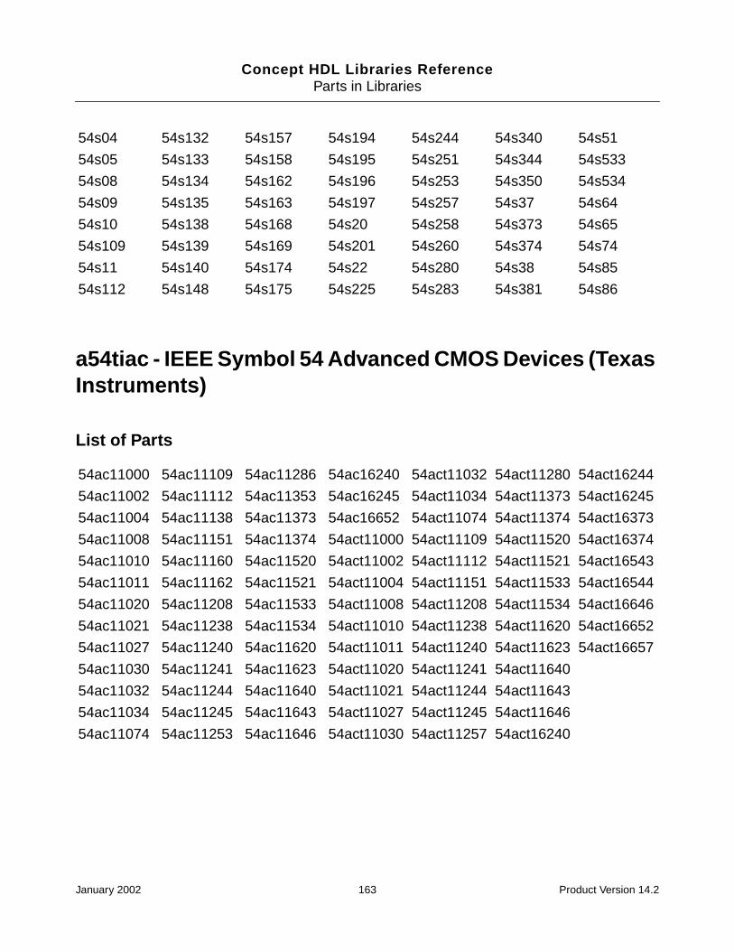
Concept HDL Libraries ReferenceParts in Libraries
a54tiac - IEEE Symbol 54 Advanced CMOS Devices (TexasInstruments)
List of Parts
54s04 54s132 54s157 54s194 54s244 54s340 54s51
54s05 54s133 54s158 54s195 54s251 54s344 54s533
54s08 54s134 54s162 54s196 54s253 54s350 54s534
54s09 54s135 54s163 54s197 54s257 54s37 54s64
54s10 54s138 54s168 54s20 54s258 54s373 54s65
54s109 54s139 54s169 54s201 54s260 54s374 54s74
54s11 54s140 54s174 54s22 54s280 54s38 54s85
54s112 54s148 54s175 54s225 54s283 54s381 54s86
54ac11000 54ac11109 54ac11286 54ac16240 54act11032 54act11280 54act16244
54ac11002 54ac11112 54ac11353 54ac16245 54act11034 54act11373 54act16245
54ac11004 54ac11138 54ac11373 54ac16652 54act11074 54act11374 54act16373
54ac11008 54ac11151 54ac11374 54act11000 54act11109 54act11520 54act16374
54ac11010 54ac11160 54ac11520 54act11002 54act11112 54act11521 54act16543
54ac11011 54ac11162 54ac11521 54act11004 54act11151 54act11533 54act16544
54ac11020 54ac11208 54ac11533 54act11008 54act11208 54act11534 54act16646
54ac11021 54ac11238 54ac11534 54act11010 54act11238 54act11620 54act16652
54ac11027 54ac11240 54ac11620 54act11011 54act11240 54act11623 54act16657
54ac11030 54ac11241 54ac11623 54act11020 54act11241 54act11640
54ac11032 54ac11244 54ac11640 54act11021 54act11244 54act11643
54ac11034 54ac11245 54ac11643 54act11027 54act11245 54act11646
54ac11074 54ac11253 54ac11646 54act11030 54act11257 54act16240
January 2002 163 Product Version 14.2
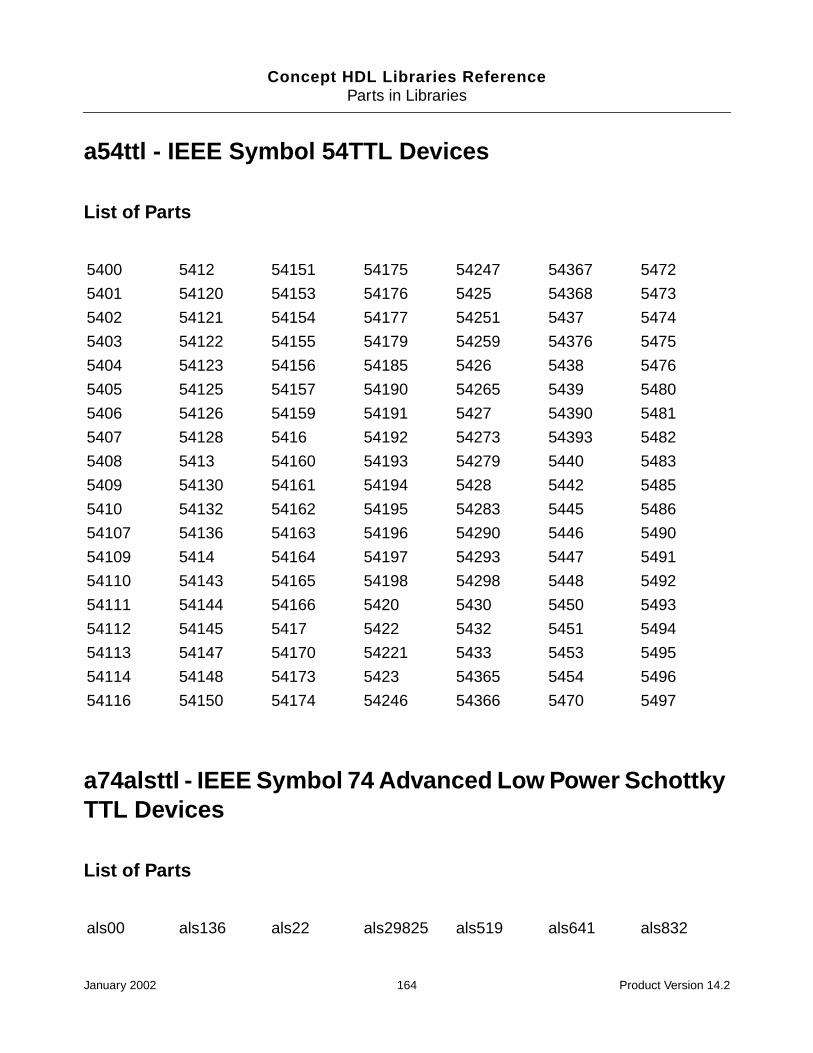
Concept HDL Libraries ReferenceParts in Libraries
a54ttl - IEEE Symbol 54TTL Devices
List of Parts
a74alsttl - IEEE Symbol 74 Advanced Low Power SchottkyTTL Devices
List of Parts
5400 5412 54151 54175 54247 54367 5472
5401 54120 54153 54176 5425 54368 5473
5402 54121 54154 54177 54251 5437 5474
5403 54122 54155 54179 54259 54376 5475
5404 54123 54156 54185 5426 5438 5476
5405 54125 54157 54190 54265 5439 5480
5406 54126 54159 54191 5427 54390 5481
5407 54128 5416 54192 54273 54393 5482
5408 5413 54160 54193 54279 5440 5483
5409 54130 54161 54194 5428 5442 5485
5410 54132 54162 54195 54283 5445 5486
54107 54136 54163 54196 54290 5446 5490
54109 5414 54164 54197 54293 5447 5491
54110 54143 54165 54198 54298 5448 5492
54111 54144 54166 5420 5430 5450 5493
54112 54145 5417 5422 5432 5451 5494
54113 54147 54170 54221 5433 5453 5495
54114 54148 54173 5423 54365 5454 5496
54116 54150 54174 54246 54366 5470 5497
als00 als136 als22 als29825 als519 als641 als832
January 2002 164 Product Version 14.2
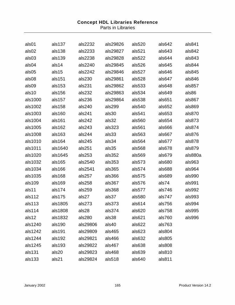
Concept HDL Libraries ReferenceParts in Libraries
als01 als137 als2232 als29826 als520 als642 als841
als02 als138 als2233 als29827 als521 als643 als842
als03 als139 als2238 als29828 als522 als644 als843
als04 als14 als2240 als29845 als526 als645 als844
als05 als15 als2242 als29846 als527 als646 als845
als08 als151 als230 als29861 als528 als647 als846
als09 als153 als231 als29862 als533 als648 als857
als10 als156 als232 als29863 als534 als649 als86
als1000 als157 als236 als29864 als538 als651 als867
als1002 als158 als240 als299 als540 als652 als869
als1003 als160 als241 als30 als541 als653 als870
als1004 als161 als242 als32 als560 als654 als873
als1005 als162 als243 als323 als561 als666 als874
als1008 als163 als244 als33 als563 als667 als876
als1010 als164 als245 als34 als564 als677 als878
als1011 als1640 als251 als35 als568 als678 als879
als1020 als1645 als253 als352 als569 als679 als880a
als1032 als165 als2540 als353 als573 als680 als963
als1034 als166 als2541 als365 als574 als688 als964
als1035 als168 als257 als366 als575 als689 als990
als109 als169 als258 als367 als576 als74 als991
als11 als174 als259 als368 als577 als746 als992
als112 als175 als27 als37 als580 als747 als993
als113 als1805 als273 als373 als614 als756 als994
als114 als1808 als28 als374 als620 als758 als995
als12 als1832 als280 als38 als621 als760 als996
als1240 als190 als29806 als40 als622 als763
als1242 als191 als29809 als465 als623 als804
als1244 als192 als29821 als466 als632 als805
als1245 als193 als29822 als467 als638 als808
als131 als20 als29823 als468 als639 als810
als133 als21 als29824 als518 als640 als811
January 2002 165 Product Version 14.2

Concept HDL Libraries ReferenceParts in Libraries
a74asttl - IEEE Symbol 74 Advanced Schottky TTLDevices
List of Parts
as00 as153 as231 as299 as632 as805a as86
as02 as157 as240 as30 as638 as808a as866
as04 as158 as241 as32 as639 as810 as867
as08 as160 as242 as323 as640 as811 as869
as10 as161 as243 as3374 as641 as821 as870
as1000 as162 as244 as34 as642 as822 as871
as1004 as163 as245 as352 as643 as823 as873
as1008 as168 as250 as353 as644 as824 as874
as1032 as169 as251 as373 as645 as825 as876
as1034 as174 as253 as374 as646 as826 as877
as1036 as175 as257 as533 as648 as832a as878
as109 as1804 as258 as534 as651 as841 as879
as11 as1805 as2620 as573 as652 as842 as880
as112 as1808 as2623 as574 as74 as843 as881
as113 as181 as264 as575 as756 as844 as882
as114 as182 as2640 as576 as757 as845 as8838
as131 as1832 as2645 as577 as758 as846 as885
as136 as194 as27 as580 as759 as850 as888
as137 as195 as280 as620 as760 as851 as890
as138 as20 as282 as621 as762 as852 as897
as139 as21 as286 as622 as763 as856 as95
as151 as230 as298 as623 as804a as857
January 2002 166 Product Version 14.2

Concept HDL Libraries ReferenceParts in Libraries
a74fact - IEEE Symbol 74 FAST Advanced CMOS TTLDevices
List of Parts
ac00 ac11521 ac257 ac654 act11240 act16646 act534
ac02 ac11533 ac258 ac7060 act11241 act16652 act540
ac04 ac11534 ac273 ac7061 act11244 act16657 act541
ac05 ac11620 ac280 ac74 act11245 act174 act563
ac08 ac11623 ac283 ac7623 act11253 act175 act564
ac10 ac11640 ac299 ac821 act11257 act190 act573
ac109 ac11643 ac32 ac825 act11258 act191 act574
ac11 ac11646 ac323 ac826 act11280 act192 act623
ac11000 ac138 ac352 ac843 act11353 act193 act640
ac11002 ac139 ac353 ac844 act11373 act20 act643
ac11004 ac14 ac373 ac845 act11374 act2151 act646
ac11008 ac151 ac374 ac846 act11520 act2152 act647
ac11010 ac153 ac377 ac86 act11521 act238 act648
ac11011 ac157 ac378 act00 act11533 act240 act649
ac11020 ac158 ac379 act02 act11534 act241 act651
ac11021 ac160 ac398 act04 act11620 act244 act652
ac11027 ac161 ac399 act05 act11623 act245 act653
ac11030 ac162 ac520 act08 act11640 act251 act654
ac11032 ac16240 ac521 act10 act11643 act253 act7060
ac11034 ac16245 ac533 act109 act11646 act257 act7061
ac11074 ac163 ac534 act11000 act138 act258 act7203a
ac11109 ac164 ac540 act11002 act139 act273 act7204a
ac11138 ac16652 ac541 act11004 act14 act280 act74
ac11151 ac168 ac563 act11008 act151 act283 act7623
ac11160 ac169 ac564 act11010 act153 act299 act7651
ac11162 ac174 ac568 act11011 act157 act32 act7813
ac112 ac175 ac569 act11020 act158 act323 act7814
ac11208 ac190 ac573 act11021 act160 act352 act821
January 2002 167 Product Version 14.2

Concept HDL Libraries ReferenceParts in Libraries
a74fast - IEEE Symbol 74 FAST TTL Devices
List of Parts
ac11240 ac191 ac574 act11027 act161 act353 act825
ac11241 ac192 ac623 act11030 act162 act373 act826
ac11244 ac193 ac640 act11032 act16240 act374 act843
ac11245 ac20 ac643 act11034 act16244 act377 act844
ac11253 ac238 ac646 act11074 act16245 act378 act845
ac11280 ac240 ac647 act11109 act163 act379 act846
ac11286 ac241 ac648 act11112 act16373 act398 act86
ac11353 ac244 ac649 act11151 act16374 act399 act8836
ac11373 ac245 ac651 act112 act164 act520 act8837
ac11374 ac251 ac652 act11208 act16543 act521
ac11520 ac253 ac653 act11238 act16544 act533
f00 f160 f21 f30640 f524 f640 f776
f02 f160a f219 f32 f533 f641 f779
f04 f161 f219a f322 f534 f642 f786
f06 f161a f240 f323 f537 f646 f803
f07 f162 f241 f350 f538 f646a f804
f08 f162a f242 f352 f539 f647 f805
f09 f163 f243 f353 f540 f648 f808
f10 f163a f244 f36 f541 f648a f821
f109 f164 f245 f365 f543 f649 f822
f11 f166 f251 f366 f544 f651 f823
f112 f168 f251a f367 f545 f651a f824
f113 f169 f253 f368 f547 f652 f825
f114 f173 f256 f37 f548 f652a f826
f1240 f174 f257 f373 f550 f653 f827
f1241 f175 f257a f374 f551 f654 f828
January 2002 168 Product Version 14.2
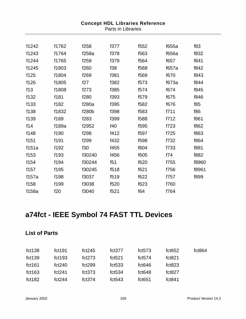
Concept HDL Libraries ReferenceParts in Libraries
a74fct - IEEE Symbol 74 FAST TTL Devices
List of Parts
f1242 f1762 f258 f377 f552 f655a f83
f1243 f1764 f258a f378 f563 f656a f832
f1244 f1765 f259 f379 f564 f657 f841
f1245 f1803 f260 f38 f568 f657a f842
f125 f1804 f269 f381 f569 f670 f843
f126 f1805 f27 f382 f573 f673a f844
f13 f1808 f273 f385 f574 f674 f845
f132 f181 f280 f393 f579 f675 f846
f133 f182 f280a f395 f582 f676 f85
f138 f1832 f280b f398 f583 f711 f86
f139 f189 f283 f399 f588 f712 f861
f14 f189a f2952 f40 f595 f723 f862
f148 f190 f298 f412 f597 f725 f863
f151 f191 f299 f432 f598 f732 f864
f151a f192 f30 f455 f604 f733 f881
f153 f193 f30240 f456 f605 f74 f882
f154 f194 f30244 f51 f620 f755 f8960
f157 f195 f30245 f518 f621 f756 f8961
f157a f198 f3037 f519 f622 f757 f899
f158 f199 f3038 f520 f623 f760
f158a f20 f3040 f521 f64 f764
fct138 fct191 fct245 fct377 fct573 fct652 fct864
fct139 fct193 fct273 fct521 fct574 fct821
fct161 fct240 fct299 fct533 fct646 fct823
fct163 fct241 fct373 fct534 fct648 fct827
fct182 fct244 fct374 fct543 fct651 fct841
January 2002 169 Product Version 14.2

Concept HDL Libraries ReferenceParts in Libraries
a74hcmos - IEEE Symbol 74 High Speed CMOS Devices
List of Parts
hc00 hc182 hc375 hc51 hct02 hct237 hct42
hc01 hc190 hc377 hc533 hct03 hct238 hct423
hc02 hc191 hc378 hc534 hct04 hct240 hct4510
hc03 hc192 hc379 hc540 hct05 hct241 hct4511
hc04 hc193 hc381 hc541 hct08 hct242 hct4514
hc05 hc194 hc386 hc563 hct10 hct243 hct4515
hc08 hc195 hc390 hc564 hct107 hct244 hct4516
hc09 hc20 hc393 hc573 hct109 hct245 hct4518
hc10 hc21 hc4002 hc574 hct11 hct251 hct4520
hc107 hc221 hc40102 hc58 hct112 hct253b hct4538
hc109 hc237 hc40103 hc583 hct123 hct257 hct4543
hc11 hc238 hc40104 hc589 hct125 hct258 hct533
hc112 hc240 hc40105 hc590 hct126 hct259 hct534
hc113 hc241 hc4015 hc595 hct132 hct27 hct540
hc114 hc242 hc4016 hc597 hct137 hct273 hct541
hc123 hc243 hc4017 hc620 hct138 hct280 hct563
hc125 hc244 hc4020 hc623 hct139 hct283 hct564
hc126 hc245 hc4024 hc640 hct14 hct299 hct573
hc132 hc251 hc4040 hc643 hct147 hct30 hct574
hc133 hc253 hc4049 hc645 hct151 hct32 hct583
hc137 hc257 hc4050 hc646 hct153 hct354 hct597
hc138 hc258 hc4051 hc648 hct154 hct356 hct620
hc139 hc259 hc4052 hc651 hct157 hct365 hct623
hc14 hc266 hc4053 hc652 hct158 hct366 hct640
hc147 hc27 hc4060 hc670 hct160 hct367 hct643
hc148 hc273 hc4066 hc688 hct161 hct368 hct646
hc151 hc280 hc4075 hc7266 hct162 hct373 hct648
hc152 hc283 hc4078 hc73 hct163 hct374 hct670
hc153 hc292 hc4094 hc74 hct164 hct377 hct688
January 2002 170 Product Version 14.2

Concept HDL Libraries ReferenceParts in Libraries
a74lcx - IEEE Symbol 74 Low Power CMOS, MultivoltageTechnology Devices
List of Parts
hc154 hc294 hc42 hc75 hct165 hct390 hct73
hc155 hc297 hc423 hc7540 hct166 hct393 hct74
hc157 hc298 hc4316 hc7541 hct173 hct4002 hct75
hc158 hc299 hc4351 hc7597 hct174 hct40102 hct7540
hc160 hc30 hc4352 hc76 hct175 hct40103 hct7541
hc161 hc32 hc4353 hc805 hct181 hct40104 hct7597
hc162 hc353 hc4510 hc808 hct182 hct40105 hct85
hc163 hc354 hc4511 hc832 hct190 hct4015 hct86
hc164 hc356 hc4514 hc85 hct191 hct4016 hct9014
hc165 hc36 hc4515 hc86 hct192 hct4017 hct9015
hc166 hc365 hc4516 hc9014 hct193 hct4020 hct9114
hc173 hc366 hc4518 hc9015 hct194 hct4024 hct9115
hc174 hc367 hc4520 hc9114 hct195 hct4040 hct93
hc175 hc368 hc4538 hc9115 hct20 hct4060 hcu04
hc180 hc373 hc4543 hc93 hct21 hct4075
hc181 hc374 hc490 hct00 hct221 hct4094
lcx00 lcx08 lcx240 lcx2952 lcx374 lcx574 lcx74
lcx02 lcx125 lcx244 lcx32 lcx543 lcx646
lcx04 lcx138 lcx245 lcx373 lcx573 lcx652
January 2002 171 Product Version 14.2

Concept HDL Libraries ReferenceParts in Libraries
a74lsttl - IEEE Symbol 74 Low Power Schottky TTLDevices
List of Parts
ls00 ls156 ls224 ls30 ls398 ls594 ls654
ls01 ls157 ls227 ls31 ls399 ls595 ls668
ls02 ls158 ls228 ls32 ls40 ls596 ls669
ls03 ls160 ls24 ls321 ls42 ls597 ls670
ls04 ls161 ls240 ls322 ls422 ls598 ls671
ls05 ls162 ls241 ls323 ls423 ls599 ls672
ls08 ls163 ls242 ls33 ls440 ls604 ls674
ls09 ls164 ls243 ls347 ls441 ls605 ls68
ls10 ls165 ls244 ls348 ls442 ls606 ls682
ls107 ls166 ls245 ls352 ls444 ls607 ls684
ls109 ls168 ls247 ls353 ls445 ls610 ls685
ls11 ls169 ls248 ls354 ls446 ls612 ls686
ls112 ls170 ls249 ls355 ls447 ls620 ls687
ls113 ls171 ls251 ls356 ls448 ls621 ls688
ls114 ls173 ls253 ls357 ls449 ls622 ls689
ls12 ls174 ls256 ls363 ls465 ls623 ls690
ls122 ls175 ls257 ls364 ls466 ls624 ls691
ls123 ls18 ls258 ls365 ls467 ls625 ls693
ls125 ls181 ls259 ls366 ls468 ls626 ls696
ls126 ls182 ls26 ls367 ls47 ls627 ls697
ls13 ls183 ls260 ls368 ls48 ls628 ls699
ls132 ls189 ls261 ls37 ls49 ls629 ls73
ls133 ls19 ls266 ls373 ls490 ls638 ls74
ls136 ls190 ls27 ls374 ls51 ls639 ls75
ls137 ls191 ls273 ls375 ls533 ls640 ls76
ls138 ls192 ls279 ls377 ls534 ls641 ls78
ls139 ls193 ls28 ls378 ls54 ls642 ls793
January 2002 172 Product Version 14.2
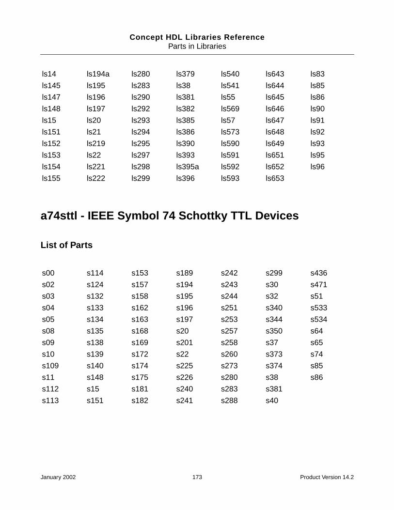
Concept HDL Libraries ReferenceParts in Libraries
a74sttl - IEEE Symbol 74 Schottky TTL Devices
List of Parts
ls14 ls194a ls280 ls379 ls540 ls643 ls83
ls145 ls195 ls283 ls38 ls541 ls644 ls85
ls147 ls196 ls290 ls381 ls55 ls645 ls86
ls148 ls197 ls292 ls382 ls569 ls646 ls90
ls15 ls20 ls293 ls385 ls57 ls647 ls91
ls151 ls21 ls294 ls386 ls573 ls648 ls92
ls152 ls219 ls295 ls390 ls590 ls649 ls93
ls153 ls22 ls297 ls393 ls591 ls651 ls95
ls154 ls221 ls298 ls395a ls592 ls652 ls96
ls155 ls222 ls299 ls396 ls593 ls653
s00 s114 s153 s189 s242 s299 s436
s02 s124 s157 s194 s243 s30 s471
s03 s132 s158 s195 s244 s32 s51
s04 s133 s162 s196 s251 s340 s533
s05 s134 s163 s197 s253 s344 s534
s08 s135 s168 s20 s257 s350 s64
s09 s138 s169 s201 s258 s37 s65
s10 s139 s172 s22 s260 s373 s74
s109 s140 s174 s225 s273 s374 s85
s11 s148 s175 s226 s280 s38 s86
s112 s15 s181 s240 s283 s381
s113 s151 s182 s241 s288 s40
January 2002 173 Product Version 14.2
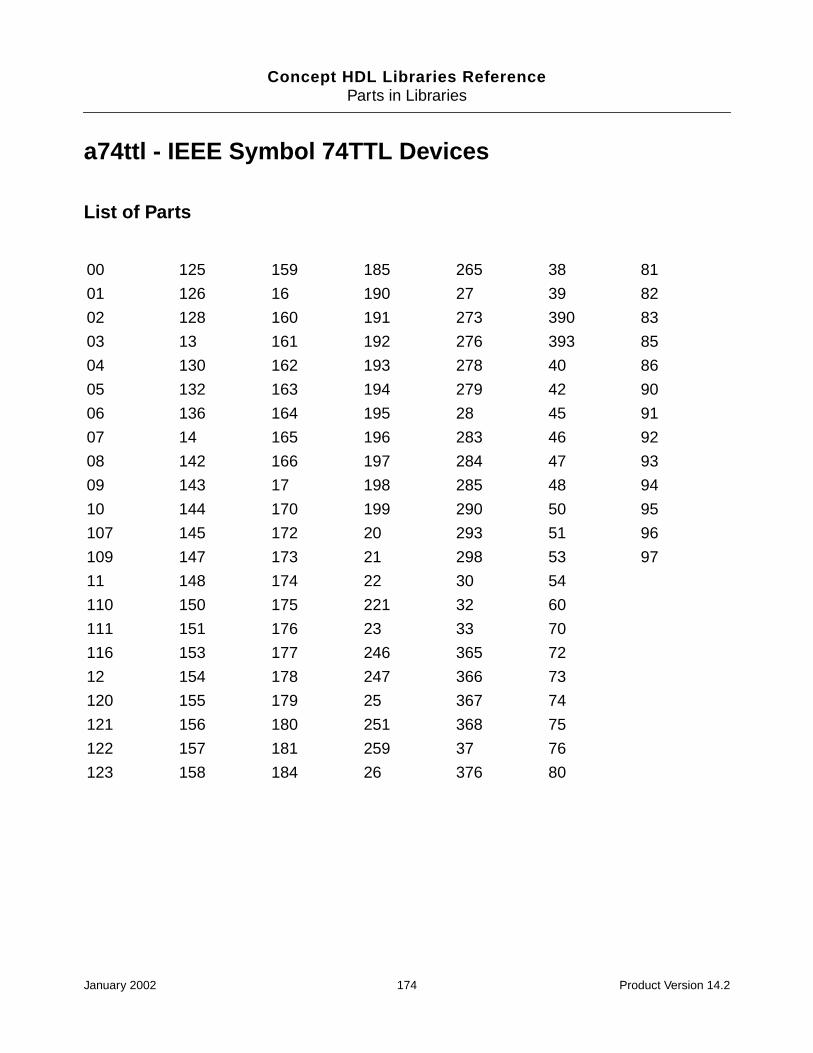
Concept HDL Libraries ReferenceParts in Libraries
a74ttl - IEEE Symbol 74TTL Devices
List of Parts
00 125 159 185 265 38 81
01 126 16 190 27 39 82
02 128 160 191 273 390 83
03 13 161 192 276 393 85
04 130 162 193 278 40 86
05 132 163 194 279 42 90
06 136 164 195 28 45 91
07 14 165 196 283 46 92
08 142 166 197 284 47 93
09 143 17 198 285 48 94
10 144 170 199 290 50 95
107 145 172 20 293 51 96
109 147 173 21 298 53 97
11 148 174 22 30 54
110 150 175 221 32 60
111 151 176 23 33 70
116 153 177 246 365 72
12 154 178 247 366 73
120 155 179 25 367 74
121 156 180 251 368 75
122 157 181 259 37 76
123 158 184 26 376 80
January 2002 174 Product Version 14.2
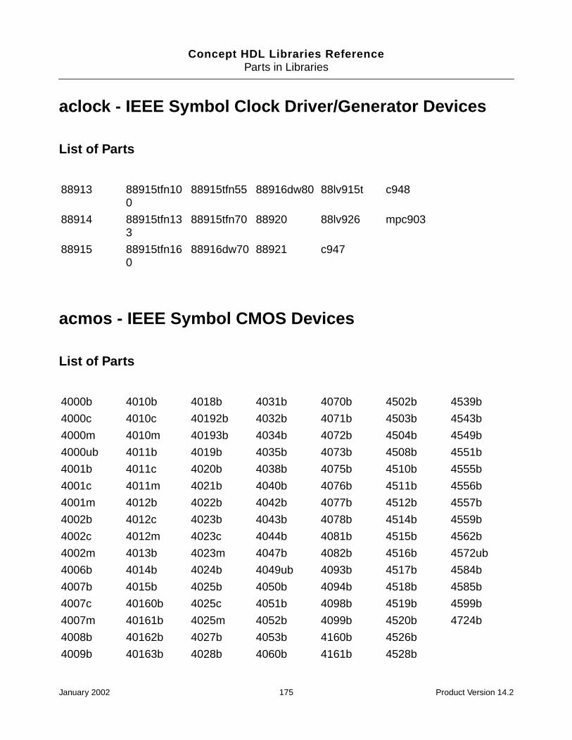
Concept HDL Libraries ReferenceParts in Libraries
aclock - IEEE Symbol Clock Driver/Generator Devices
List of Parts
acmos - IEEE Symbol CMOS Devices
List of Parts
88913 88915tfn100
88915tfn55 88916dw80 88lv915t c948
88914 88915tfn133
88915tfn70 88920 88lv926 mpc903
88915 88915tfn160
88916dw70 88921 c947
4000b 4010b 4018b 4031b 4070b 4502b 4539b
4000c 4010c 40192b 4032b 4071b 4503b 4543b
4000m 4010m 40193b 4034b 4072b 4504b 4549b
4000ub 4011b 4019b 4035b 4073b 4508b 4551b
4001b 4011c 4020b 4038b 4075b 4510b 4555b
4001c 4011m 4021b 4040b 4076b 4511b 4556b
4001m 4012b 4022b 4042b 4077b 4512b 4557b
4002b 4012c 4023b 4043b 4078b 4514b 4559b
4002c 4012m 4023c 4044b 4081b 4515b 4562b
4002m 4013b 4023m 4047b 4082b 4516b 4572ub
4006b 4014b 4024b 4049ub 4093b 4517b 4584b
4007b 4015b 4025b 4050b 4094b 4518b 4585b
4007c 40160b 4025c 4051b 4098b 4519b 4599b
4007m 40161b 4025m 4052b 4099b 4520b 4724b
4008b 40162b 4027b 4053b 4160b 4526b
4009b 40163b 4028b 4060b 4161b 4528b
January 2002 175 Product Version 14.2
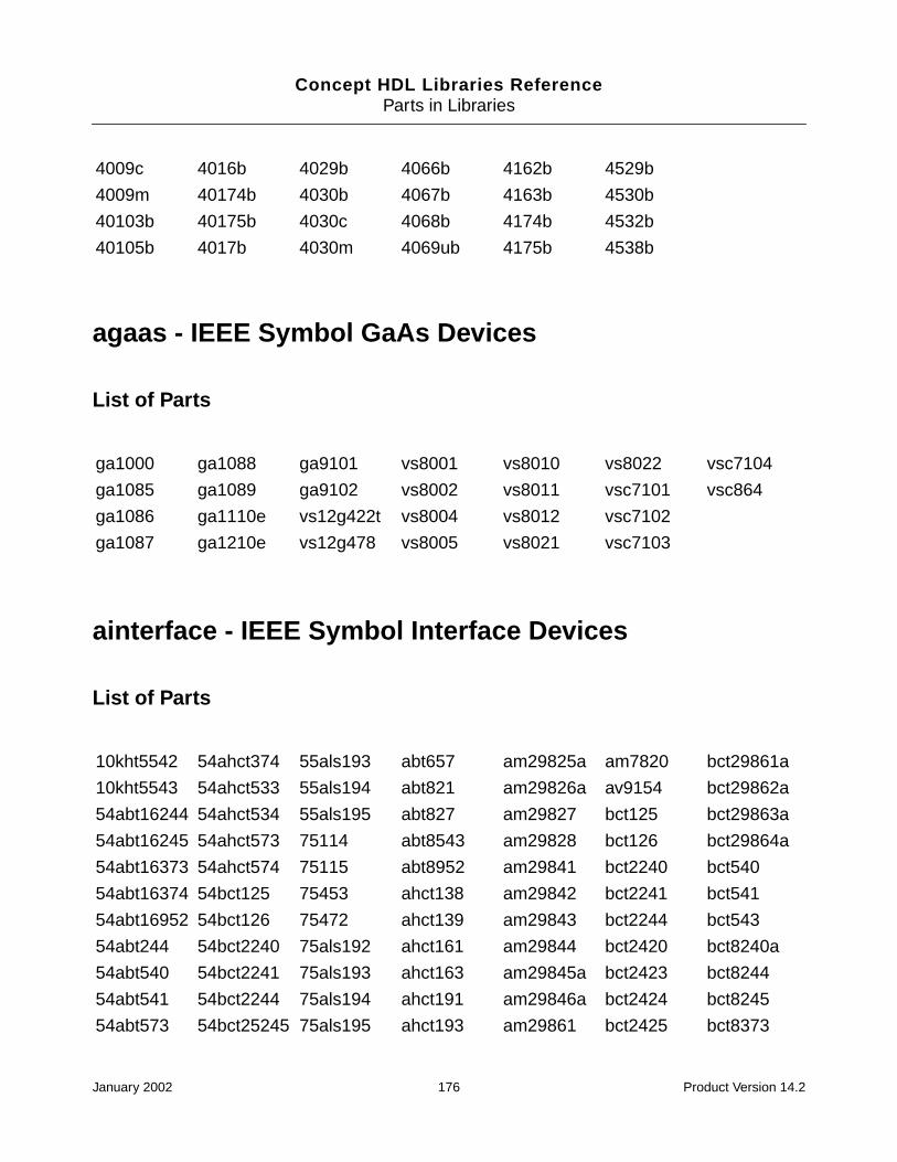
Concept HDL Libraries ReferenceParts in Libraries
agaas - IEEE Symbol GaAs Devices
List of Parts
ainterface - IEEE Symbol Interface Devices
List of Parts
4009c 4016b 4029b 4066b 4162b 4529b
4009m 40174b 4030b 4067b 4163b 4530b
40103b 40175b 4030c 4068b 4174b 4532b
40105b 4017b 4030m 4069ub 4175b 4538b
ga1000 ga1088 ga9101 vs8001 vs8010 vs8022 vsc7104
ga1085 ga1089 ga9102 vs8002 vs8011 vsc7101 vsc864
ga1086 ga1110e vs12g422t vs8004 vs8012 vsc7102
ga1087 ga1210e vs12g478 vs8005 vs8021 vsc7103
10kht5542 54ahct374 55als193 abt657 am29825a am7820 bct29861a
10kht5543 54ahct533 55als194 abt821 am29826a av9154 bct29862a
54abt16244 54ahct534 55als195 abt827 am29827 bct125 bct29863a
54abt16245 54ahct573 75114 abt8543 am29828 bct126 bct29864a
54abt16373 54ahct574 75115 abt8952 am29841 bct2240 bct540
54abt16374 54bct125 75453 ahct138 am29842 bct2241 bct541
54abt16952 54bct126 75472 ahct139 am29843 bct2244 bct543
54abt244 54bct2240 75als192 ahct161 am29844 bct2420 bct8240a
54abt540 54bct2241 75als193 ahct163 am29845a bct2423 bct8244
54abt541 54bct2244 75als194 ahct191 am29846a bct2424 bct8245
54abt573 54bct25245 75als195 ahct193 am29861 bct2425 bct8373
January 2002 176 Product Version 14.2

Concept HDL Libraries ReferenceParts in Libraries
alsttl - 74 Advanced Low Power Schottky TTL Devices
List of Parts
54abt574 54bct2827b abt16244a ahct240 am29862 bct25245 bct8374
54abt646a 54bct29827b
abt16245 ahct244 am29863 bct2827a ds1387
54abt657 54bct29862b
abt16373 ahct245 am29864 bct2828a ds3695
54abt8543 54bct29863b
abt16374 ahct299 am29945a bct29821 fb2033
54abt8952 54bct540 abt16500 ahct373 am29c821 bct29823 lvt125
54ahct138 54bct541 abt16952 ahct374 am29c823 bct29824 lvt16244a
54ahct139 54bct543 abt18245 ahct534 am29c827a bct29827a lvt16245
54ahct161 54bct8240a abt18502 ahct573 am29c828a bct29828a lvt240
54ahct163 54bct8244 abt18504 ahct574 am29c841 bct29833 lvt244a
54ahct182 54bct8245 abt240 am26ls29 am29c843 bct29834 lvt245
54ahct191 54bct8373 abt244 am26ls31 am29c861a bct29841 lvt574
54ahct193 54bct8374 abt245 am26ls32 am29c863a bct29842 mc88pl117
54ahct240 55114 abt540 am29806 am29c921 bct29843 mt8952
54ahct244 55115 abt541 am29809 am29c923 bct29844 scan18245t
54ahct245 55453 abt543 am29821a am29c927 bct29845 scanpsc100f
54ahct273 55472 abt573 am29822a am29c928 bct29846 spt7814
54ahct299 55als161 abt574 am29823a am29c961 bct29853 uc5601
54ahct373 55als192 abt646 am29824a am29c963 bct29854
als00 als136 als22 als29825 als519 als641 als832
als01 als137 als2232 als29826 als520 als642 als841
als02 als138 als2233 als29827 als521 als643 als842
als03 als139 als2238 als29828 als522 als644 als843
als04 als14 als2240 als29845 als526 als645 als844
January 2002 177 Product Version 14.2
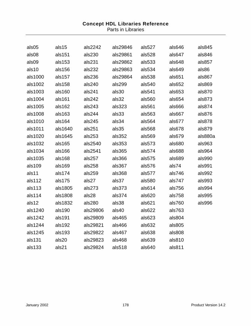
Concept HDL Libraries ReferenceParts in Libraries
als05 als15 als2242 als29846 als527 als646 als845
als08 als151 als230 als29861 als528 als647 als846
als09 als153 als231 als29862 als533 als648 als857
als10 als156 als232 als29863 als534 als649 als86
als1000 als157 als236 als29864 als538 als651 als867
als1002 als158 als240 als299 als540 als652 als869
als1003 als160 als241 als30 als541 als653 als870
als1004 als161 als242 als32 als560 als654 als873
als1005 als162 als243 als323 als561 als666 als874
als1008 als163 als244 als33 als563 als667 als876
als1010 als164 als245 als34 als564 als677 als878
als1011 als1640 als251 als35 als568 als678 als879
als1020 als1645 als253 als352 als569 als679 als880a
als1032 als165 als2540 als353 als573 als680 als963
als1034 als166 als2541 als365 als574 als688 als964
als1035 als168 als257 als366 als575 als689 als990
als109 als169 als258 als367 als576 als74 als991
als11 als174 als259 als368 als577 als746 als992
als112 als175 als27 als37 als580 als747 als993
als113 als1805 als273 als373 als614 als756 als994
als114 als1808 als28 als374 als620 als758 als995
als12 als1832 als280 als38 als621 als760 als996
als1240 als190 als29806 als40 als622 als763
als1242 als191 als29809 als465 als623 als804
als1244 als192 als29821 als466 als632 als805
als1245 als193 als29822 als467 als638 als808
als131 als20 als29823 als468 als639 als810
als133 als21 als29824 als518 als640 als811
January 2002 178 Product Version 14.2

Concept HDL Libraries ReferenceParts in Libraries
amemory - IEEE Symbol Memory Devices
List of Parts
2114al_1 am27s281 cy7c170 hm5116400 idt72225la n82s123 tmm2089c
2147h_1 am27s35 cy7c185_35 hm51256 idt72235b n82s126 tmm2089p_35
2148h_3 am27s37 cy7c186 hm514100 idt72245b n82s129 tmm2089p_45
2164a_15 am27s45 cy7c194 hm514170 idt7m134s n82s130 tmm41256
24s10 am27s47 cy7c196 hm514190 idt7m135 n82s131 tmm41464
24s41 am2864ae cy7c199 hm514260 idt7m203s n82s135 tms2149_3
24s81 am2864be cy7c225 hm514270 idt7m204 n82s137 tms2167_4
24sa10 am28c256 cy7c235_30 hm514280 ims1420_45
n82s147 tms27c010
27128 am29434 cy7c245 hm514400 ims1620 n82s181 tms27c49
2716_1 am29520 cy7c251 hm514800 lh5497 n82s183 tms27c512
27256 am29705 cy7c254 hm514900 m5m23168 n82s185 tms29f256
2732a_2 am29c334 cy7c258 hm51w4160
m5m41000 n82s191 tms29f258
27512 am29f010 cy7c259 hm51w4260
m5m44c256p_10
n82s23 tms29f259
2764_2 am29f040 cy7c261 hm5216165 m5m4c1000p_10
nmc2142a tms4164_12
27c128 am7205a cy7c263_35 hm5216805 m5m4c264 p4c187 tms416400
27c202_90 am9114 cy7c264 hm5241605 m5m5258 pdm41024s tms4256e9_15
27c210_13 am9122_25 cy7c265_15 hm5241605c
m79018 pdm41028s tms4257
27c210_15 am9124 cy7c265_40 hm5283206 mcm10474_15
pdm41096s tms44100
27c210_20 am9128_70 cy7c266 hm6116_2 mcm10474_25
s188 tms44165
27c256 am9150_20 cy7c269 hm6167 mcm1423 s2816a tms44400
January 2002 179 Product Version 14.2
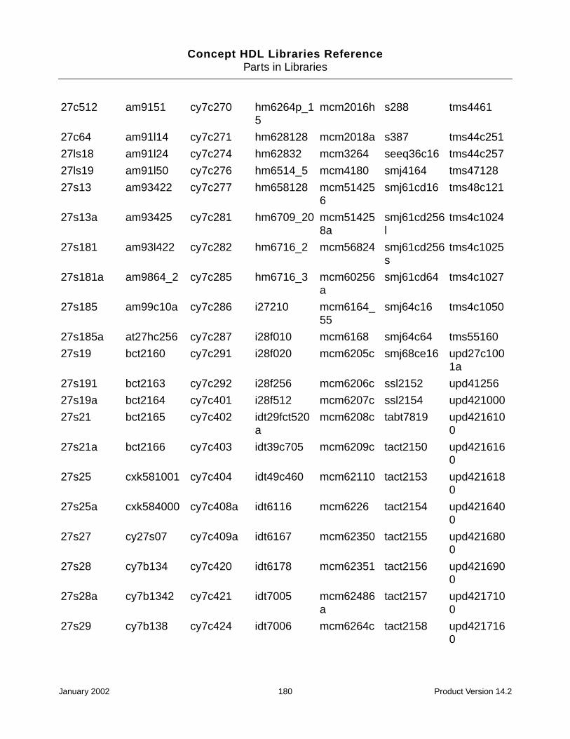
Concept HDL Libraries ReferenceParts in Libraries
27c512 am9151 cy7c270 hm6264p_15
mcm2016h s288 tms4461
27c64 am91l14 cy7c271 hm628128 mcm2018a s387 tms44c251
27ls18 am91l24 cy7c274 hm62832 mcm3264 seeq36c16 tms44c257
27ls19 am91l50 cy7c276 hm6514_5 mcm4180 smj4164 tms47128
27s13 am93422 cy7c277 hm658128 mcm514256
smj61cd16 tms48c121
27s13a am93425 cy7c281 hm6709_20 mcm514258a
smj61cd256l
tms4c1024
27s181 am93l422 cy7c282 hm6716_2 mcm56824 smj61cd256s
tms4c1025
27s181a am9864_2 cy7c285 hm6716_3 mcm60256a
smj61cd64 tms4c1027
27s185 am99c10a cy7c286 i27210 mcm6164_55
smj64c16 tms4c1050
27s185a at27hc256 cy7c287 i28f010 mcm6168 smj64c64 tms55160
27s19 bct2160 cy7c291 i28f020 mcm6205c smj68ce16 upd27c1001a
27s191 bct2163 cy7c292 i28f256 mcm6206c ssl2152 upd41256
27s19a bct2164 cy7c401 i28f512 mcm6207c ssl2154 upd421000
27s21 bct2165 cy7c402 idt29fct520a
mcm6208c tabt7819 upd4216100
27s21a bct2166 cy7c403 idt39c705 mcm6209c tact2150 upd4216160
27s25 cxk581001 cy7c404 idt49c460 mcm62110 tact2153 upd4216180
27s25a cxk584000 cy7c408a idt6116 mcm6226 tact2154 upd4216400
27s27 cy27s07 cy7c409a idt6167 mcm62350 tact2155 upd4216800
27s28 cy7b134 cy7c420 idt6178 mcm62351 tact2156 upd4216900
27s28a cy7b1342 cy7c421 idt7005 mcm62486a
tact2157 upd4217100
27s29 cy7b138 cy7c424 idt7006 mcm6264c tact2158 upd4217160
January 2002 180 Product Version 14.2
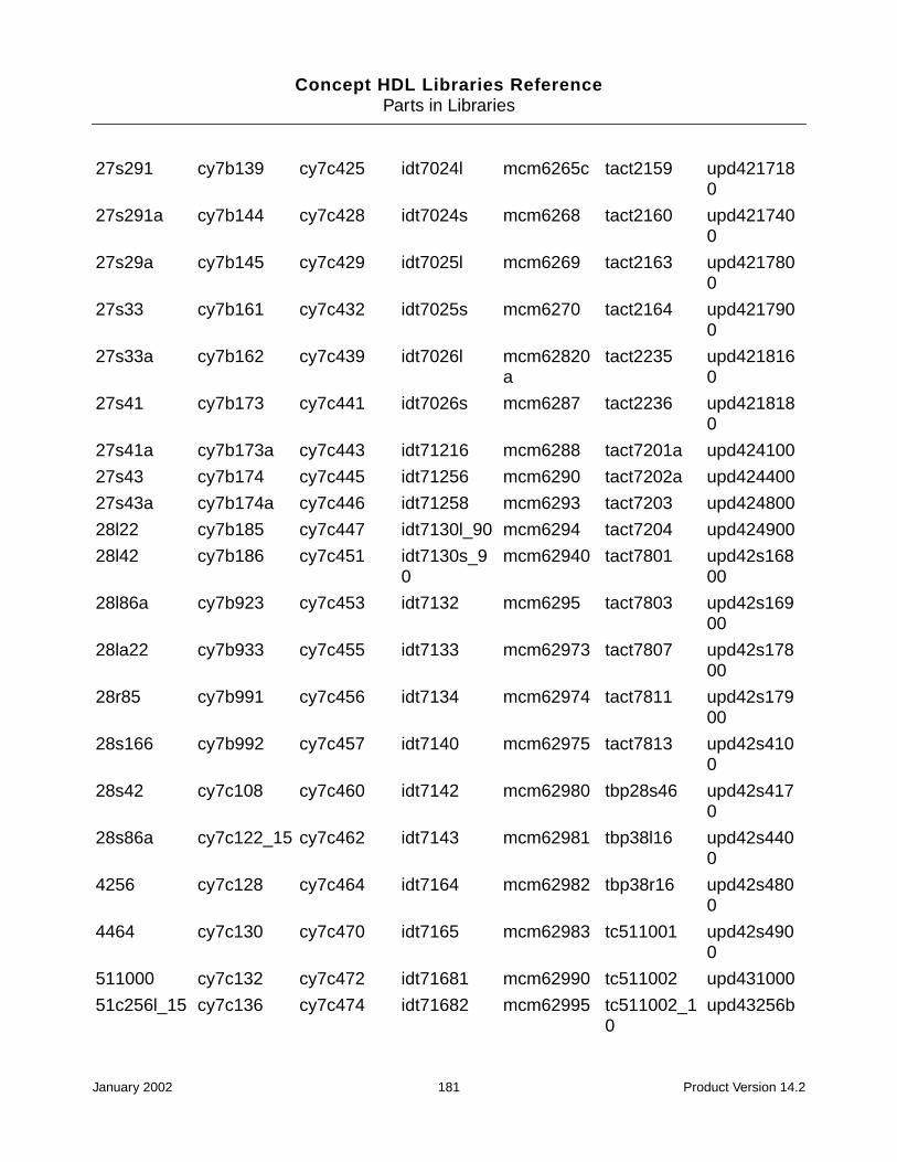
Concept HDL Libraries ReferenceParts in Libraries
27s291 cy7b139 cy7c425 idt7024l mcm6265c tact2159 upd4217180
27s291a cy7b144 cy7c428 idt7024s mcm6268 tact2160 upd4217400
27s29a cy7b145 cy7c429 idt7025l mcm6269 tact2163 upd4217800
27s33 cy7b161 cy7c432 idt7025s mcm6270 tact2164 upd4217900
27s33a cy7b162 cy7c439 idt7026l mcm62820a
tact2235 upd4218160
27s41 cy7b173 cy7c441 idt7026s mcm6287 tact2236 upd4218180
27s41a cy7b173a cy7c443 idt71216 mcm6288 tact7201a upd424100
27s43 cy7b174 cy7c445 idt71256 mcm6290 tact7202a upd424400
27s43a cy7b174a cy7c446 idt71258 mcm6293 tact7203 upd424800
28l22 cy7b185 cy7c447 idt7130l_90 mcm6294 tact7204 upd424900
28l42 cy7b186 cy7c451 idt7130s_90
mcm62940 tact7801 upd42s16800
28l86a cy7b923 cy7c453 idt7132 mcm6295 tact7803 upd42s16900
28la22 cy7b933 cy7c455 idt7133 mcm62973 tact7807 upd42s17800
28r85 cy7b991 cy7c456 idt7134 mcm62974 tact7811 upd42s17900
28s166 cy7b992 cy7c457 idt7140 mcm62975 tact7813 upd42s4100
28s42 cy7c108 cy7c460 idt7142 mcm62980 tbp28s46 upd42s4170
28s86a cy7c122_15 cy7c462 idt7143 mcm62981 tbp38l16 upd42s4400
4256 cy7c128 cy7c464 idt7164 mcm62982 tbp38r16 upd42s4800
4464 cy7c130 cy7c470 idt7165 mcm62983 tc511001 upd42s4900
511000 cy7c132 cy7c472 idt71681 mcm62990 tc511002 upd431000
51c256l_15 cy7c136 cy7c474 idt71682 mcm62995 tc511002_10
upd43256b
January 2002 181 Product Version 14.2

Concept HDL Libraries ReferenceParts in Libraries
asttl - 74 Advanced Schottky TTL Devices
List of Parts
51c64l_12 cy7c140 cy8c166_25 idt7187 mcm6664_15
tc514102 upd434000
7202 cy7c142 cy8c185_35 idt7188 mcm67b618
tc514256 upd446_5
7203 cy7c146 cy93422 idt7198 mcm8256 tc514258 upd488170
7204 cy7c147 dm74ls471 idt71982 mk45180 tc514402 ws57c256
act7202 cy7c148 dm74s472 idt7200 mt4c1024 tc528128 ws57c43
als6302 cy7c149 dm74s473 idt7201a mt4c4256 tc5517b ws57c45
am2168 cy7c150_15 dm87sr474 idt7205 mt5c2564 tc55257 ws57c49
am2169 cy7c157 dm87sr476 idt7206 mt5c2568 tc5564p_15 ws57c65
am27c1024 cy7c161 f1600_55 idt72205b n82hs187 tc5565 x2004
am27ls191 cy7c162 f410 idt72215 n82hs189 tial2232 x2210
am27ps191 cy7c166_25 hb56a19b_8a
idt72215b n82hs195 tial2233 x28256
am27ps291 cy7c167_25 hm4864_2 idt72215la n82hs321 tial2238 x2864
am27ps41 cy7c168 hm50256 idt72225 n82hs641 tial232
am27s190 cy7c169_25 hm50464 idt72225b n82s115 tial236
as00 as160 as245 as374 as652 as845 as890
as02 as161 as250 as533 as74 as846 as897
as04 as162 as251 as534 as756 as850 as95
as08 as163 as253 as573 as757 as851
as10 as168 as257 as574 as758 as852
as1000 as169 as258 as575 as759 as856
as1004 as174 as2620 as576 as760 as857
as1008 as175 as2623 as577 as762 as86
as1032 as1804 as264 as580 as763 as866
as1034 as1805 as2640 as620 as804a as867
January 2002 182 Product Version 14.2

Concept HDL Libraries ReferenceParts in Libraries
clock - Clock Driver/Generator Devices
List of Parts
cmos - CMOS Devices
List of Parts
as1036 as1808 as2645 as621 as805a as869
as109 as181 as27 as622 as808a as870
as11 as182 as280 as623 as810 as871
as112 as1832 as282 as632 as811 as873
as113 as194 as286 as638 as821 as874
as114 as195 as298 as639 as822 as876
as131 as20 as299 as640 as823 as877
as136 as21 as30 as641 as824 as878
as137 as230 as32 as642 as825 as879
as138 as231 as323 as643 as826 as880
as139 as240 as3374 as644 as832a as881
as151 as241 as34 as645 as841 as882
as153 as242 as352 as646 as842 as8838
as157 as243 as353 as648 as843 as885
as158 as244 as373 as651 as844 as888
88913 88915tfn100 88915tfn55 88921 c947
88914 88915tfn133 88915tfn70 88lv915t c948
88915 88915tfn160 88920 88lv926 mpc903
4000b 40109b 4018b 4032b 4072b 4508b 4552b
January 2002 183 Product Version 14.2
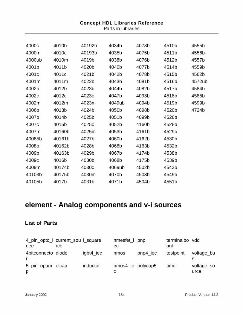
Concept HDL Libraries ReferenceParts in Libraries
element - Analog components and v-i sources
List of Parts
4000c 4010b 40192b 4034b 4073b 4510b 4555b
4000m 4010c 40193b 4035b 4075b 4511b 4556b
4000ub 4010m 4019b 4038b 4076b 4512b 4557b
4001b 4011b 4020b 4040b 4077b 4514b 4559b
4001c 4011c 4021b 4042b 4078b 4515b 4562b
4001m 4011m 4022b 4043b 4081b 4516b 4572ub
4002b 4012b 4023b 4044b 4082b 4517b 4584b
4002c 4012c 4023c 4047b 4093b 4518b 4585b
4002m 4012m 4023m 4049ub 4094b 4519b 4599b
4006b 4013b 4024b 4050b 4098b 4520b 4724b
4007b 4014b 4025b 4051b 4099b 4526b
4007c 4015b 4025c 4052b 4160b 4528b
4007m 40160b 4025m 4053b 4161b 4529b
40085b 40161b 4027b 4060b 4162b 4530b
4008b 40162b 4028b 4066b 4163b 4532b
4009b 40163b 4029b 4067b 4174b 4538b
4009c 4016b 4030b 4068b 4175b 4539b
4009m 40174b 4030c 4069ub 4502b 4543b
40103b 40175b 4030m 4070b 4503b 4549b
40105b 4017b 4031b 4071b 4504b 4551b
4_pin_opto_ieee
current_source
i_square nmesfet_iec
pnp terminalboard
vdd
4bitconnector
diode igbt4_iec nmos pnp4_iec testpoint voltage_bus
5_pin_opamp
elcap inductor nmos4_iec
polycap5 timer voltage_source
January 2002 184 Product Version 14.2

Concept HDL Libraries ReferenceParts in Libraries
fact - 74 FAST Advanced CMOS TTL Devices
List of Parts
7_pin_opamp
full_bridge interlock noiseoutput
polyind5 transformer
voltageprobe
ac fuse lamp npn pwr_nmos transmission
vss
antenna gnd led npn4_iec pwr_pmos tunneldiode
winding
attenuator gnd1 loopantenna pjfet reg_adjust v_pulse windingr
bttryd gnda mov pjfet_iec reg_fixed v_sinusoidal
zenerdiode
capacitor gndd multitaptransformer
pmesfet resistor v_square
chassis ground njfet pmesfet_iec
series_bridge
variables
connector i_pulse njfet_iec pmos simple_winding
vcc
current_probe
i_sinusoidal nmesfet pmos4_iec
tappedinductor
vdc
ac00 ac11521 ac257 ac654 act11240 act16646 act534
ac02 ac11533 ac258 ac7060 act11241 act16652 act540
ac04 ac11534 ac273 ac7061 act11244 act16657 act541
ac05 ac11620 ac280 ac74 act11245 act174 act563
ac08 ac11623 ac283 ac7623 act11253 act175 act564
ac10 ac11640 ac299 ac821 act11257 act190 act573
ac109 ac11643 ac32 ac825 act11258 act191 act574
ac11 ac11646 ac323 ac826 act11280 act192 act623
ac11000 ac138 ac352 ac843 act11353 act193 act640
ac11002 ac139 ac353 ac844 act11373 act20 act643
ac11004 ac14 ac373 ac845 act11374 act2151 act646
ac11008 ac151 ac374 ac846 act11520 act2152 act647
January 2002 185 Product Version 14.2
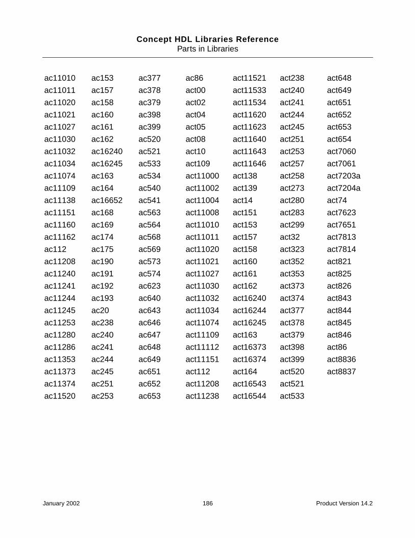
Concept HDL Libraries ReferenceParts in Libraries
ac11010 ac153 ac377 ac86 act11521 act238 act648
ac11011 ac157 ac378 act00 act11533 act240 act649
ac11020 ac158 ac379 act02 act11534 act241 act651
ac11021 ac160 ac398 act04 act11620 act244 act652
ac11027 ac161 ac399 act05 act11623 act245 act653
ac11030 ac162 ac520 act08 act11640 act251 act654
ac11032 ac16240 ac521 act10 act11643 act253 act7060
ac11034 ac16245 ac533 act109 act11646 act257 act7061
ac11074 ac163 ac534 act11000 act138 act258 act7203a
ac11109 ac164 ac540 act11002 act139 act273 act7204a
ac11138 ac16652 ac541 act11004 act14 act280 act74
ac11151 ac168 ac563 act11008 act151 act283 act7623
ac11160 ac169 ac564 act11010 act153 act299 act7651
ac11162 ac174 ac568 act11011 act157 act32 act7813
ac112 ac175 ac569 act11020 act158 act323 act7814
ac11208 ac190 ac573 act11021 act160 act352 act821
ac11240 ac191 ac574 act11027 act161 act353 act825
ac11241 ac192 ac623 act11030 act162 act373 act826
ac11244 ac193 ac640 act11032 act16240 act374 act843
ac11245 ac20 ac643 act11034 act16244 act377 act844
ac11253 ac238 ac646 act11074 act16245 act378 act845
ac11280 ac240 ac647 act11109 act163 act379 act846
ac11286 ac241 ac648 act11112 act16373 act398 act86
ac11353 ac244 ac649 act11151 act16374 act399 act8836
ac11373 ac245 ac651 act112 act164 act520 act8837
ac11374 ac251 ac652 act11208 act16543 act521
ac11520 ac253 ac653 act11238 act16544 act533
January 2002 186 Product Version 14.2
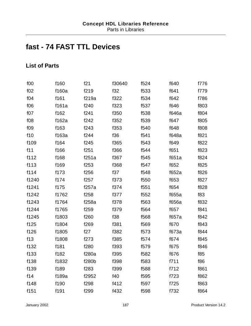
Concept HDL Libraries ReferenceParts in Libraries
fast - 74 FAST TTL Devices
List of Parts
f00 f160 f21 f30640 f524 f640 f776
f02 f160a f219 f32 f533 f641 f779
f04 f161 f219a f322 f534 f642 f786
f06 f161a f240 f323 f537 f646 f803
f07 f162 f241 f350 f538 f646a f804
f08 f162a f242 f352 f539 f647 f805
f09 f163 f243 f353 f540 f648 f808
f10 f163a f244 f36 f541 f648a f821
f109 f164 f245 f365 f543 f649 f822
f11 f166 f251 f366 f544 f651 f823
f112 f168 f251a f367 f545 f651a f824
f113 f169 f253 f368 f547 f652 f825
f114 f173 f256 f37 f548 f652a f826
f1240 f174 f257 f373 f550 f653 f827
f1241 f175 f257a f374 f551 f654 f828
f1242 f1762 f258 f377 f552 f655a f83
f1243 f1764 f258a f378 f563 f656a f832
f1244 f1765 f259 f379 f564 f657 f841
f1245 f1803 f260 f38 f568 f657a f842
f125 f1804 f269 f381 f569 f670 f843
f126 f1805 f27 f382 f573 f673a f844
f13 f1808 f273 f385 f574 f674 f845
f132 f181 f280 f393 f579 f675 f846
f133 f182 f280a f395 f582 f676 f85
f138 f1832 f280b f398 f583 f711 f86
f139 f189 f283 f399 f588 f712 f861
f14 f189a f2952 f40 f595 f723 f862
f148 f190 f298 f412 f597 f725 f863
f151 f191 f299 f432 f598 f732 f864
January 2002 187 Product Version 14.2
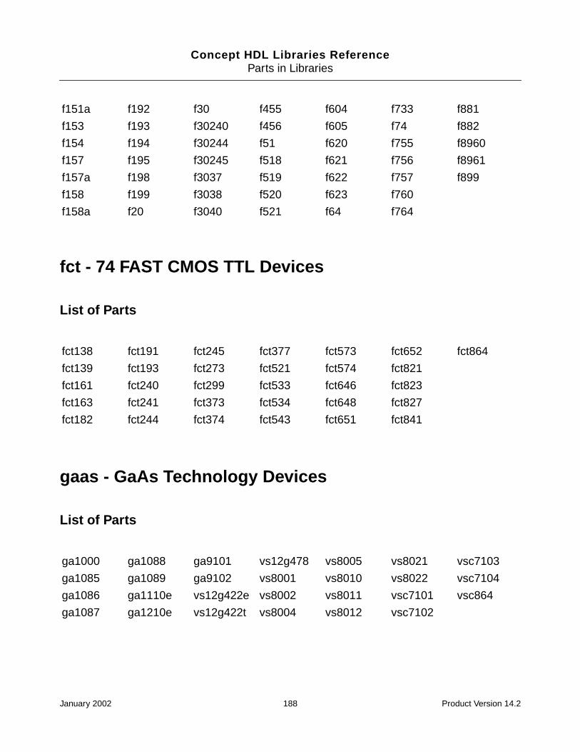
Concept HDL Libraries ReferenceParts in Libraries
fct - 74 FAST CMOS TTL Devices
List of Parts
gaas - GaAs Technology Devices
List of Parts
f151a f192 f30 f455 f604 f733 f881
f153 f193 f30240 f456 f605 f74 f882
f154 f194 f30244 f51 f620 f755 f8960
f157 f195 f30245 f518 f621 f756 f8961
f157a f198 f3037 f519 f622 f757 f899
f158 f199 f3038 f520 f623 f760
f158a f20 f3040 f521 f64 f764
fct138 fct191 fct245 fct377 fct573 fct652 fct864
fct139 fct193 fct273 fct521 fct574 fct821
fct161 fct240 fct299 fct533 fct646 fct823
fct163 fct241 fct373 fct534 fct648 fct827
fct182 fct244 fct374 fct543 fct651 fct841
ga1000 ga1088 ga9101 vs12g478 vs8005 vs8021 vsc7103
ga1085 ga1089 ga9102 vs8001 vs8010 vs8022 vsc7104
ga1086 ga1110e vs12g422e vs8002 vs8011 vsc7101 vsc864
ga1087 ga1210e vs12g422t vs8004 vs8012 vsc7102
January 2002 188 Product Version 14.2
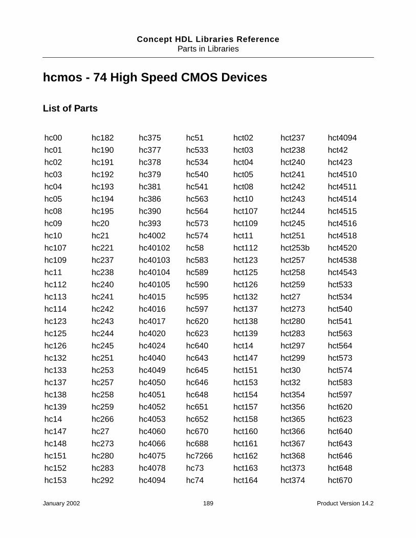
Concept HDL Libraries ReferenceParts in Libraries
hcmos - 74 High Speed CMOS Devices
List of Parts
hc00 hc182 hc375 hc51 hct02 hct237 hct4094
hc01 hc190 hc377 hc533 hct03 hct238 hct42
hc02 hc191 hc378 hc534 hct04 hct240 hct423
hc03 hc192 hc379 hc540 hct05 hct241 hct4510
hc04 hc193 hc381 hc541 hct08 hct242 hct4511
hc05 hc194 hc386 hc563 hct10 hct243 hct4514
hc08 hc195 hc390 hc564 hct107 hct244 hct4515
hc09 hc20 hc393 hc573 hct109 hct245 hct4516
hc10 hc21 hc4002 hc574 hct11 hct251 hct4518
hc107 hc221 hc40102 hc58 hct112 hct253b hct4520
hc109 hc237 hc40103 hc583 hct123 hct257 hct4538
hc11 hc238 hc40104 hc589 hct125 hct258 hct4543
hc112 hc240 hc40105 hc590 hct126 hct259 hct533
hc113 hc241 hc4015 hc595 hct132 hct27 hct534
hc114 hc242 hc4016 hc597 hct137 hct273 hct540
hc123 hc243 hc4017 hc620 hct138 hct280 hct541
hc125 hc244 hc4020 hc623 hct139 hct283 hct563
hc126 hc245 hc4024 hc640 hct14 hct297 hct564
hc132 hc251 hc4040 hc643 hct147 hct299 hct573
hc133 hc253 hc4049 hc645 hct151 hct30 hct574
hc137 hc257 hc4050 hc646 hct153 hct32 hct583
hc138 hc258 hc4051 hc648 hct154 hct354 hct597
hc139 hc259 hc4052 hc651 hct157 hct356 hct620
hc14 hc266 hc4053 hc652 hct158 hct365 hct623
hc147 hc27 hc4060 hc670 hct160 hct366 hct640
hc148 hc273 hc4066 hc688 hct161 hct367 hct643
hc151 hc280 hc4075 hc7266 hct162 hct368 hct646
hc152 hc283 hc4078 hc73 hct163 hct373 hct648
hc153 hc292 hc4094 hc74 hct164 hct374 hct670
January 2002 189 Product Version 14.2

Concept HDL Libraries ReferenceParts in Libraries
interface - Interface Devices
List of Parts
hc154 hc294 hc42 hc75 hct165 hct377 hct688
hc155 hc297 hc423 hc7540 hct166 hct390 hct73
hc157 hc298 hc4316 hc7541 hct173 hct393 hct74
hc158 hc299 hc4351 hc7597 hct174 hct4002 hct75
hc160 hc30 hc4352 hc76 hct175 hct40102 hct7540
hc161 hc32 hc4353 hc805 hct181 hct40103 hct7541
hc162 hc353 hc4510 hc808 hct182 hct40104 hct7597
hc163 hc354 hc4511 hc832 hct190 hct40105 hct85
hc164 hc356 hc4514 hc85 hct191 hct4015 hct86
hc165 hc36 hc4515 hc86 hct192 hct4016 hct9014
hc166 hc365 hc4516 hc9014 hct193 hct4017 hct9015
hc173 hc366 hc4518 hc9015 hct194 hct4020 hct9114
hc174 hc367 hc4520 hc9114 hct195 hct4024 hct9115
hc175 hc368 hc4538 hc9115 hct20 hct4040 hct93
hc180 hc373 hc4543 hc93 hct21 hct4060 hcu04
hc181 hc374 hc490 hct00 hct221 hct4075
100kt5542 54ahct574 75472 ahct193 am29862 bct2240 bct8373
100kt5543 54bct125 75als161 ahct240 am29863 bct2241 bct8374
10kht5542 54bct126 75als170 ahct244 am29864 bct2244 cgs100115
10kht5543 54bct2240 75als192 ahct245 am29941 bct2420 cgs74b2525
54abt16244 54bct2241 75als193 ahct299 am29943 bct2423 cgs74c2525
54abt16245 54bct2244 75als194 ahct373 am29945a bct2424 cgs74c2526
54abt16373 54bct25245 75als195 ahct374 am29c676 bct2425 cgs74ct2525
54abt16374 54bct2827b abt16244a ahct534 am29c818 bct25245 cgs74ct2526
January 2002 190 Product Version 14.2
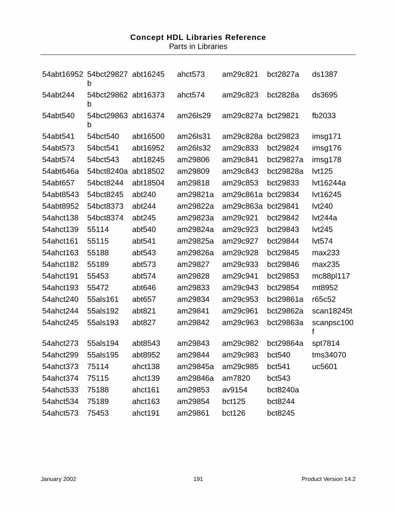
Concept HDL Libraries ReferenceParts in Libraries
54abt16952 54bct29827b
abt16245 ahct573 am29c821 bct2827a ds1387
54abt244 54bct29862b
abt16373 ahct574 am29c823 bct2828a ds3695
54abt540 54bct29863b
abt16374 am26ls29 am29c827a bct29821 fb2033
54abt541 54bct540 abt16500 am26ls31 am29c828a bct29823 imsg171
54abt573 54bct541 abt16952 am26ls32 am29c833 bct29824 imsg176
54abt574 54bct543 abt18245 am29806 am29c841 bct29827a imsg178
54abt646a 54bct8240a abt18502 am29809 am29c843 bct29828a lvt125
54abt657 54bct8244 abt18504 am29818 am29c853 bct29833 lvt16244a
54abt8543 54bct8245 abt240 am29821a am29c861a bct29834 lvt16245
54abt8952 54bct8373 abt244 am29822a am29c863a bct29841 lvt240
54ahct138 54bct8374 abt245 am29823a am29c921 bct29842 lvt244a
54ahct139 55114 abt540 am29824a am29c923 bct29843 lvt245
54ahct161 55115 abt541 am29825a am29c927 bct29844 lvt574
54ahct163 55188 abt543 am29826a am29c928 bct29845 max233
54ahct182 55189 abt573 am29827 am29c933 bct29846 max235
54ahct191 55453 abt574 am29828 am29c941 bct29853 mc88pl117
54ahct193 55472 abt646 am29833 am29c943 bct29854 mt8952
54ahct240 55als161 abt657 am29834 am29c953 bct29861a r65c52
54ahct244 55als192 abt821 am29841 am29c961 bct29862a scan18245t
54ahct245 55als193 abt827 am29842 am29c963 bct29863a scanpsc100f
54ahct273 55als194 abt8543 am29843 am29c982 bct29864a spt7814
54ahct299 55als195 abt8952 am29844 am29c983 bct540 tms34070
54ahct373 75114 ahct138 am29845a am29c985 bct541 uc5601
54ahct374 75115 ahct139 am29846a am7820 bct543
54ahct533 75188 ahct161 am29853 av9154 bct8240a
54ahct534 75189 ahct163 am29854 bct125 bct8244
54ahct573 75453 ahct191 am29861 bct126 bct8245
January 2002 191 Product Version 14.2

Concept HDL Libraries ReferenceParts in Libraries
lcx - 74 Low Power CMOS, Multivoltage TechnologyDevices
List of Parts
lsttl - 74 Low Power Schottky TTL Devices
List of Parts
lcx00 lcx08 lcx240 lcx2952 lcx374 lcx574 lcx74
lcx02 lcx125 lcx244 lcx32 lcx543 lcx646
lcx04 lcx138 lcx245 lcx373 lcx573 lcx652
ls00 ls156 ls224 ls30 ls398 ls598 ls671
ls01 ls157 ls227 ls31 ls399 ls599 ls672
ls02 ls158 ls228 ls32 ls40 ls604 ls674
ls03 ls160 ls24 ls321 ls42 ls605 ls68
ls04 ls161 ls240 ls322 ls422 ls606 ls682
ls05 ls162 ls241 ls323 ls423 ls607 ls684
ls08 ls163 ls242 ls33 ls445 ls610 ls685
ls09 ls164 ls243 ls347 ls446 ls612 ls686
ls10 ls165 ls244 ls348 ls447 ls620 ls687
ls107 ls166 ls245 ls352 ls448 ls621 ls688
ls109 ls168 ls247 ls353 ls449 ls622 ls689
ls11 ls169 ls248 ls354 ls465 ls623 ls690
ls112 ls170 ls249 ls355 ls466 ls624 ls691
ls113 ls171 ls251 ls356 ls467 ls625 ls693
ls114 ls173 ls253 ls357 ls468 ls626 ls696
ls12 ls174 ls256 ls363 ls47 ls627 ls697
ls122 ls175 ls257 ls364 ls48 ls628 ls699
ls123 ls18 ls258 ls365 ls49 ls629 ls73
January 2002 192 Product Version 14.2

Concept HDL Libraries ReferenceParts in Libraries
memory - Memory Devices
List of Parts
ls125 ls181 ls259 ls366 ls490 ls638 ls74
ls126 ls182 ls26 ls367 ls51 ls639 ls75
ls13 ls183 ls260 ls368 ls533 ls640 ls76
ls132 ls189 ls261 ls37 ls534 ls641 ls78
ls133 ls19 ls266 ls373 ls54 ls642 ls793
ls136 ls190 ls27 ls374 ls540 ls643 ls83
ls137 ls191 ls273 ls375 ls541 ls644 ls85
ls138 ls192 ls279 ls377 ls55 ls645 ls86
ls139 ls193 ls28 ls378 ls569 ls646 ls90
ls14 ls194a ls280 ls379 ls57 ls647 ls91
ls145 ls195 ls283 ls38 ls573 ls648 ls92
ls147 ls196 ls290 ls381 ls590 ls649 ls93
ls148 ls197 ls292 ls382 ls591 ls651 ls95
ls15 ls20 ls293 ls385 ls592 ls652 ls96
ls151 ls21 ls294 ls386 ls593 ls653
ls152 ls219 ls295 ls390 ls594 ls654
ls153 ls22 ls297 ls393 ls595 ls668
ls154 ls221 ls298 ls395a ls596 ls669
ls155 ls222 ls299 ls396 ls597 ls670
2114al_1 am27s45 cy7c186 hm514260 ims1420_45
n82s181 tms29f258
2147h_1 am27s47 cy7c194 hm514270 ims1620 n82s183 tms29f259
2148h_3 am2864ae cy7c196 hm514280 lh5497 n82s185 tms4164_12
2164a_15 am2864be cy7c199 hm514400 m5m23168 n82s191 tms416400
24s10 am28c256 cy7c225 hm514800 m5m41000 n82s23 tms4256e9_15
January 2002 193 Product Version 14.2

Concept HDL Libraries ReferenceParts in Libraries
24s41 am29434 cy7c235_30 hm514900 m5m44c256p_10
nmc2142a tms4257
24s81 am29520 cy7c245 hm51w4160
m5m4c1000p_10
p4c187 tms44100
24sa10 am29705 cy7c251 hm51w4260
m5m4c264 pdm41024s tms44165
27128 am29c334 cy7c254 hm5241605 m5m5258 pdm41028s tms44400
2716_1 am29f010 cy7c258 hm5283206 m79018 pdm41096s tms4461
27256 am29f040 cy7c259 hm6116_2 mcm10474_15
s188 tms44c251
2732a_2 am57402 cy7c261 hm6167 mcm10474_25
s2816a tms44c257
27512 am7205a cy7c263_35 hm6264p_15
mcm1423 s288 tms47128
2764_2 am9114 cy7c264 hm628128 mcm2016h s387 tms48c121
27c128 am9122_25 cy7c265_15 hm62832 mcm2018a seeq36c16 tms4c1024
27c202_90 am9124 cy7c265_40 hm6514_5 mcm3264 smj4164 tms4c1025
27c210_13 am9128_70 cy7c266 hm658128 mcm4180 smj61cd16 tms4c1027
27c210_15 am9150_20 cy7c269 hm6709_20 mcm514256
smj61cd256l
tms4c1050
27c210_20 am9151 cy7c270 hm6716_2 mcm514258a
smj61cd256s
tms55160
27c256 am91l14 cy7c271 hm6716_3 mcm56824 smj61cd64 upd23c16000
27c512 am91l24 cy7c274 i27011 mcm60256a
smj64c16 upd23c8000
27c64 am91l50 cy7c276 i27210 mcm6164_55
smj64c64 upd27c1001a
27ls18 am93422 cy7c277 i27960c mcm6168 smj68ce16 upd41256
27ls19 am93425 cy7c281 i27960k mcm6205c ssl2152 upd421000
27s13 am93l422 cy7c282 i28f010 mcm6206c ssl2154 upd4216100
27s13a am9864_2 cy7c285 i28f020 mcm6207c tabt7819 upd4216160
27s181 am99c10a cy7c286 i28f256 mcm6208c tact2140a upd4216180
January 2002 194 Product Version 14.2
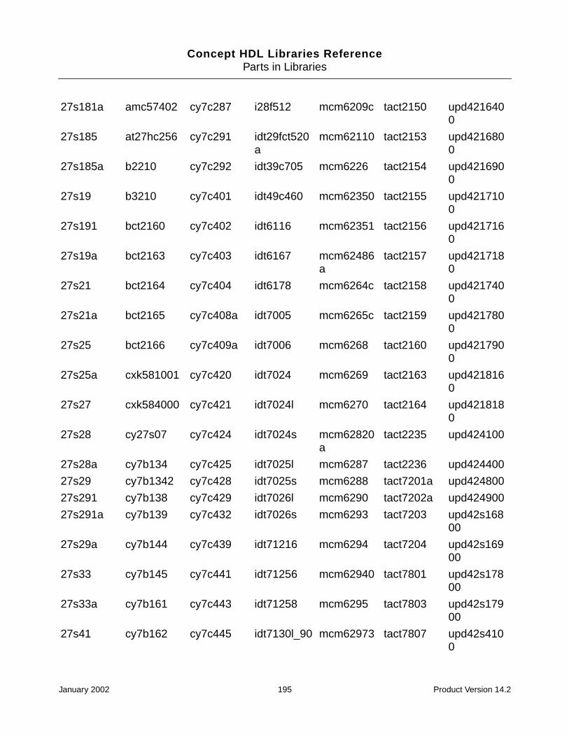
Concept HDL Libraries ReferenceParts in Libraries
27s181a amc57402 cy7c287 i28f512 mcm6209c tact2150 upd4216400
27s185 at27hc256 cy7c291 idt29fct520a
mcm62110 tact2153 upd4216800
27s185a b2210 cy7c292 idt39c705 mcm6226 tact2154 upd4216900
27s19 b3210 cy7c401 idt49c460 mcm62350 tact2155 upd4217100
27s191 bct2160 cy7c402 idt6116 mcm62351 tact2156 upd4217160
27s19a bct2163 cy7c403 idt6167 mcm62486a
tact2157 upd4217180
27s21 bct2164 cy7c404 idt6178 mcm6264c tact2158 upd4217400
27s21a bct2165 cy7c408a idt7005 mcm6265c tact2159 upd4217800
27s25 bct2166 cy7c409a idt7006 mcm6268 tact2160 upd4217900
27s25a cxk581001 cy7c420 idt7024 mcm6269 tact2163 upd4218160
27s27 cxk584000 cy7c421 idt7024l mcm6270 tact2164 upd4218180
27s28 cy27s07 cy7c424 idt7024s mcm62820a
tact2235 upd424100
27s28a cy7b134 cy7c425 idt7025l mcm6287 tact2236 upd424400
27s29 cy7b1342 cy7c428 idt7025s mcm6288 tact7201a upd424800
27s291 cy7b138 cy7c429 idt7026l mcm6290 tact7202a upd424900
27s291a cy7b139 cy7c432 idt7026s mcm6293 tact7203 upd42s16800
27s29a cy7b144 cy7c439 idt71216 mcm6294 tact7204 upd42s16900
27s33 cy7b145 cy7c441 idt71256 mcm62940 tact7801 upd42s17800
27s33a cy7b161 cy7c443 idt71258 mcm6295 tact7803 upd42s17900
27s41 cy7b162 cy7c445 idt7130l_90 mcm62973 tact7807 upd42s4100
January 2002 195 Product Version 14.2

Concept HDL Libraries ReferenceParts in Libraries
27s41a cy7b173 cy7c446 idt7130s_90
mcm62974 tact7811 upd42s4100l
27s43 cy7b173a cy7c447 idt7132 mcm62975 tact7813 upd42s4170
27s43a cy7b174 cy7c451 idt7133 mcm62980 tbp28s46 upd42s4400
28l22 cy7b174a cy7c453 idt7134 mcm62981 tbp38l16 upd42s4800
28l42 cy7b185 cy7c455 idt7140 mcm62982 tbp38r16 upd42s4900
28l86a cy7b186 cy7c456 idt7142 mcm62983 tc511001 upd431000
28la22 cy7b923 cy7c457 idt7143 mcm62990 tc511002 upd43256b
28r85 cy7b933 cy7c460 idt7164 mcm62995 tc511002_10
upd434000
28s166 cy7b991 cy7c462 idt7165 mcm6664_15
tc514102 upd446_5
28s42 cy7b992 cy7c464 idt71681 mcm67b618
tc514256 upd488170
28s86a cy7c108 cy7c470 idt71682 mcm8256 tc514258 ux28hc256
4256 cy7c122_15 cy7c472 idt7187 mk45180 tc514402 ws57c256
4464 cy7c128 cy7c474 idt7188 mk6116 tc528128 ws57c43
511000 cy7c130 cy8c166_25 idt7198 mmi57402j tc5517b ws57c45
51c256l_15 cy7c132 cy8c185_35 idt71982 mt4c1024 tc55257 ws57c49
51c64l_12 cy7c136 cy93422 idt7200 mt4c4256 tc5564p_15 ws57c65
7202 cy7c140 dm74ls471 idt7201a mt5c2564 tc5565 x2004
7203 cy7c142 dm74s472 idt7205 mt5c2568 tial2232 x2210
7204 cy7c146 dm74s473 idt7206 n82hs187 tial2233 x28256
act7202 cy7c147 dm87sr474 idt72205b n82hs189 tial2238 x2864
als6302 cy7c148 dm87sr476 idt72215 n82hs195 tial232
am2168 cy7c149 f1600_55 idt72215b n82hs321 tial236
am2169 cy7c150_15 f410 idt72215la n82hs641 tmm2089c
am27c1024 cy7c157 hb56a19b_8a
idt72225 n82s115 tmm2089p_35
am27ls191 cy7c161 hm4864_2 idt72225b n82s123 tmm2089p_45
am27ps191 cy7c162 hm50256 idt72225la n82s126 tmm41256
January 2002 196 Product Version 14.2

Concept HDL Libraries ReferenceParts in Libraries
pld - Programmable Logic Devices
List of Parts
am27ps291 cy7c166_25 hm50464 idt72235b n82s129 tmm41464
am27ps41 cy7c167_25 hm5116400 idt72245b n82s130 tms2149_3
am27s190 cy7c168 hm51256 idt7m134s n82s131 tms2167_4
am27s281 cy7c169_25 hm514100 idt7m135 n82s135 tms27c010
am27s35 cy7c170 hm514170 idt7m203s n82s137 tms27c49
am27s37 cy7c185_35 hm514190 idt7m204 n82s147 tms29f256
a1010_100
ep320 isplsi1016 pal16l8 peel20cg10 plus20r4 xc3195_160
a1010_44 ep600 isplsi1024 pal16ld8 peel22cv10 plus20r6 xc3195_175
a1010_68 ep610a isplsi1032 pal16p8a phd16n8 plus20r8 xc3195_208
a1010_84 ep630 isplsi1048 pal16r4 plc153 plus405 xc3195_84
a1020_100
ep900 mach110 pal16r6 plc16v8 plx448 xc4002a_100
a1020_44 ep910 mach120 pal16r8 plc18v8z plx464 xc4002a_120
a1020_68 epf81188_232
mach130 pal16ra8 plc20v8 ql12x16_100
xc4002a_84
a1020_84 epf81188_240
mach210 pal16rp4a plc42va12 ql12x16_68 xc4003_100
a1225_100
epf8452_160pga
mach215 pal16rp6a plc473 ql12x16_84 xc4003_120
a1225_84 epf8452_160pqfp
mach220 pal16rp8a pldc18g8 ql8x12a_100
xc4003_84
a1240_132
epf8452_84 mach230 pal18l4 pldc20g10 ql8x12a_44 xc4004a_120
a1240_144
epm5016 mach435 pal18p8 plhs153 ql8x12a_68 xc4004a_160
January 2002 197 Product Version 14.2

Concept HDL Libraries ReferenceParts in Libraries
a1240_84 epm5032 pal10016p4a
pal18v8 plhs16l8a tib82s105 xc4004a_84
a1280_160
epm5064 pal10016p8 pal20c1 plhs18p8 tib82s167b xc4005_156
a1280_172
epm5128 pal10016rd8
pal20l10a plhs473 xc1736 xc4005_160
a1280_176
epm5130 pal10020eg8
pal20l2 plhs501 xc1765 xc4005_164
a1425_133
epm5130_84 pal10020ev8
pal20l8 plhs502 xc2018_68 xc4005_84
a1425_160
epm5192 pal1016p4a pal20r4 pls100 xc2018_84 xc4005a_208
a1460_208
epm7032 pal1016p8 pal20r6 pls101 xc2064_48 xc4006_156
am29cpl154
epm7096 pal1016rd8 pal20r8 pls105 xc2064_68 xc4006_160
ampal22p10
epm7096_100
pal10h20eg8
pal20ra10 pls153 xc3020_100
xc4006_208
at22v10 epm7096_68 pal10h20ev8
pal20rs10 pls155 xc3020_68 xc4008_191
atv2500 epm7128_100
pal10h20p8 pal20rs4 pls157 xc3020_84 xc4008_208
atv750 epm7128_160
pal10h8 pal20rs8 pls159a xc3030_100
xc4010_191
cy100e301
epm7128_84 pal10l8 pal20s10 pls161 xc3030_44 xc4010_196
cy100e302
epm7160_84 pal12h6 pal20x10a pls167 xc3030_68 xc4010_208
cy10e301 epm7192 pal12l10 pal20x4a pls168 xc3030_84 xc7236_44
cy10e302 epm7256 pal12l6 pal20x8a pls173 xc3042_100
xc7272_68
cy7c330 eps464 pal14h4 pal22v10 pls179 xc3042_132
xc7272_84
cy7c331 gal16v8 pal14l4 pal22vp10 plus105 xc3042_84 xc73108_144
cy7c332 gal16v8a pal14l8 pal32vx10 plus153 xc3064_132
xc73108_84
January 2002 198 Product Version 14.2

Concept HDL Libraries ReferenceParts in Libraries
rcacmos - Advanced CMOS Series of RCA
List of Parts
cy7c335 gal18v10 pal16c1 pal6l16a plus16l8 xc3064_160
cy7c361 gal20v8 pal16h2 pal8l14a plus16r4 xc3064_84
ep1210 gal20v8a pal16h8 palce16v8 plus16r6 xc3090_160
ep1800 gal22v10 pal16hd8 palce22v10 plus16r8 xc3090_164
ep1810 gal26cv12 pal16l2 palce26v12 plus173 xc3090_175
ep310 gal6001 pal16l6 peel18cv8 plus20l8 xc3090_84
ac00 ac163 ac283 ac564 act138 act244 act378
ac02 ac174 ac32 ac573 act139 act245 act379
ac04 ac175 ac352 ac574 act151 act251 act533
ac08 ac20 ac353 ac623 act153 act253 act534
ac10 ac238 ac373 ac646 act157 act257 act540
ac109 ac240 ac374 ac74 act158 act258 act541
ac112 ac241 ac377 ac86 act161 act273 act563
ac138 ac244 ac378 act00 act163 act283 act564
ac139 ac245 ac379 act02 act174 act32 act573
ac151 ac251 ac533 act04 act175 act352 act574
ac153 ac253 ac534 act08 act20 act353 act623
ac157 ac257 ac540 act10 act238 act373 act646
ac158 ac258 ac541 act109 act240 act374 act74
ac161 ac273 ac563 act112 act241 act377 act86
January 2002 199 Product Version 14.2

Concept HDL Libraries ReferenceParts in Libraries
standard - Page Borders, Taps, Declarations, and otherbasic schematic symbols
List of Parts
sttl - 74 Schottky TTL Devices
List of Parts
10 merge 9 merge cadence asize page
f size page msb tap slash time_directives
2 merge a size page cadence bsize page
flag not slice valid a sizepage
3 merge alias ctap hdl_decs offpage supply_0 valid b sizepage
4 merge aoutport d size page inport origin supply_1 verilog_decs
5 merge b size page declarations ioport outport synonym vhdl_decs
6 merge bit tap define lnkport pin names synop_dec
7 merge bufport drawing lsb tap sign extend tap
8 merge c size page e size page menu sim_directives
tie
s00 s114 s153 s189 s242 s299 s436
s02 s124 s157 s194 s243 s30 s471
s03 s132 s158 s195 s244 s32 s51
s04 s133 s162 s196 s251 s340 s533
s05 s134 s163 s197 s253 s344 s534
s08 s135 s168 s20 s257 s350 s64
s09 s138 s169 s201 s258 s37 s65
s10 s139 s172 s22 s260 s373 s74
s109 s140 s174 s225 s273 s374 s85
January 2002 200 Product Version 14.2
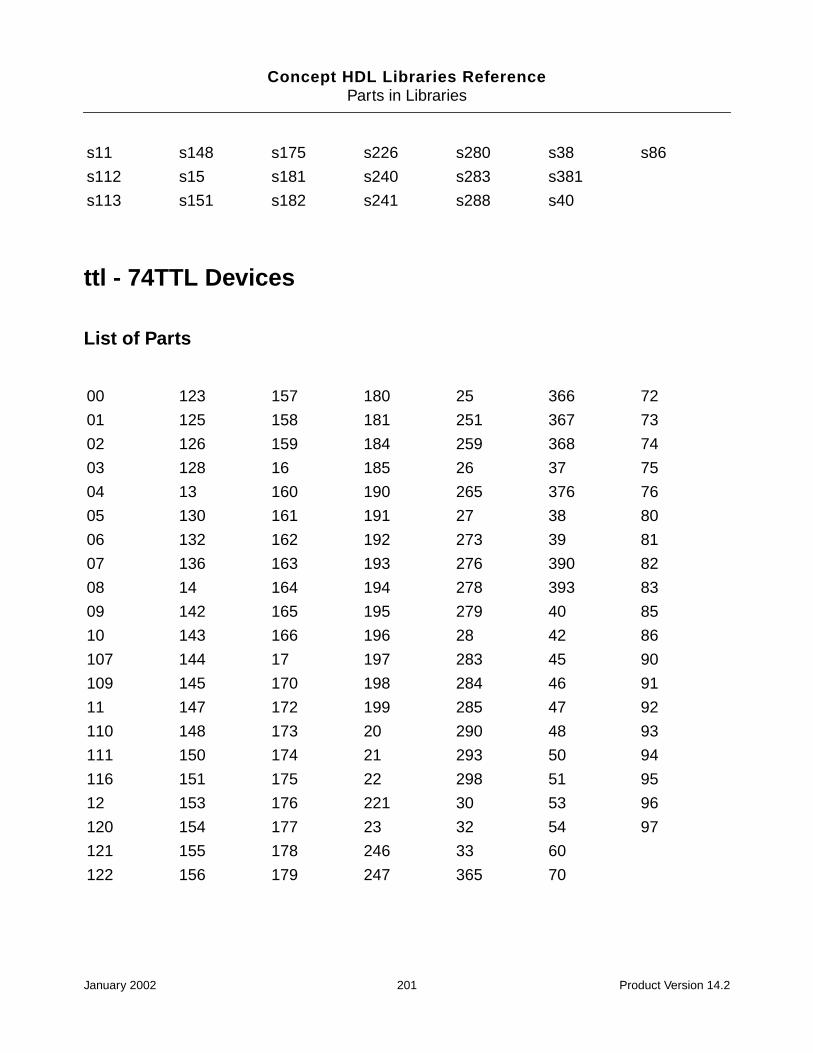
Concept HDL Libraries ReferenceParts in Libraries
ttl - 74TTL Devices
List of Parts
s11 s148 s175 s226 s280 s38 s86
s112 s15 s181 s240 s283 s381
s113 s151 s182 s241 s288 s40
00 123 157 180 25 366 72
01 125 158 181 251 367 73
02 126 159 184 259 368 74
03 128 16 185 26 37 75
04 13 160 190 265 376 76
05 130 161 191 27 38 80
06 132 162 192 273 39 81
07 136 163 193 276 390 82
08 14 164 194 278 393 83
09 142 165 195 279 40 85
10 143 166 196 28 42 86
107 144 17 197 283 45 90
109 145 170 198 284 46 91
11 147 172 199 285 47 92
110 148 173 20 290 48 93
111 150 174 21 293 50 94
116 151 175 22 298 51 95
12 153 176 221 30 53 96
120 154 177 23 32 54 97
121 155 178 246 33 60
122 156 179 247 365 70
January 2002 201 Product Version 14.2
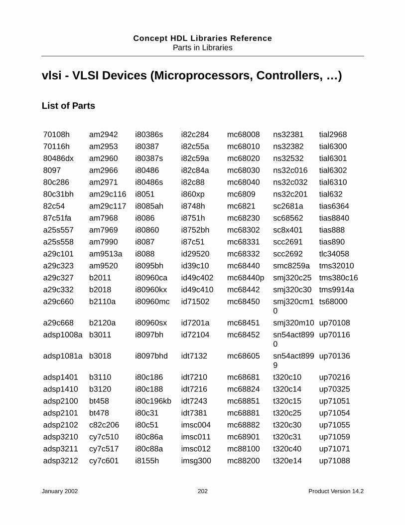
Concept HDL Libraries ReferenceParts in Libraries
vlsi - VLSI Devices (Microprocessors, Controllers, …)
List of Parts
70108h am2942 i80386s i82c284 mc68008 ns32381 tial2968
70116h am2953 i80387 i82c55a mc68010 ns32382 tial6300
80486dx am2960 i80387s i82c59a mc68020 ns32532 tial6301
8097 am2966 i80486 i82c84a mc68030 ns32c016 tial6302
80c286 am2971 i80486s i82c88 mc68040 ns32c032 tial6310
80c31bh am29c116 i8051 i860xp mc6809 ns32c201 tial632
82c54 am29c117 i8085ah i8748h mc6821 sc2681a tias6364
87c51fa am7968 i8086 i8751h mc68230 sc68562 tias8840
a25s557 am7969 i80860 i8752bh mc68302 sc8x401 tias888
a25s558 am7990 i8087 i87c51 mc68331 scc2691 tias890
a29c101 am9513a i8088 id29520 mc68332 scc2692 tlc34058
a29c323 am9520 i8095bh id39c10 mc68440 smc8259a tms32010
a29c327 b2011 i80960ca id49c402 mc68440p smj320c25 tms380c16
a29c332 b2018 i80960kx id49c410 mc68442 smj320c30 tms9914a
a29c660 b2110a i80960mc id71502 mc68450 smj320cm10
ts68000
a29c668 b2120a i80960sx id7201a mc68451 smj320m10 up70108
adsp1008a b3011 i8097bh id72104 mc68452 sn54act8990
up70116
adsp1081a b3018 i8097bhd idt7132 mc68605 sn54act8999
up70136
adsp1401 b3110 i80c186 idt7210 mc68681 t320c10 up70216
adsp1410 b3120 i80c188 idt7216 mc68824 t320c14 up70325
adsp2100 bt458 i80c196kb idt7243 mc68851 t320c15 up71051
adsp2101 bt478 i80c31 idt7381 mc68881 t320c25 up71054
adsp2102 c82c206 i80c51 imsc004 mc68882 t320c30 up71055
adsp3210 cy7c510 i80c86a imsc011 mc68901 t320c31 up71059
adsp3211 cy7c517 i80c88a imsc012 mc88100 t320c40 up71071
adsp3212 cy7c601 i8155h imsg300 mc88200 t320e14 up71088
January 2002 202 Product Version 14.2

Concept HDL Libraries ReferenceParts in Libraries
adsp3220 cy7c611 i82188 imst222 mm74c922 t370c010 upd70108
adsp3221 cy7c909 i82258 imst225 mpg68000 t370c050 upd70116
adsp3222 cy7c910 i82288 imst400 mpg68020 t370c056 vic068
adsp8018 cy7c9101 i82351 imst425 mpg68030 tact1010 w33c93a
am29000 cy7c911 i82352_0 imst800 mpg6821 tact2440 we_dsp16a
am2901 d21064 i82352_1 imst801 mpg68442 tact29116 wedsp32c_grid
am2902 dp8428 i82352_3 imst805 mpg68hc11 tact8818 wedsp32c_quad
am29027 dp8429 i82355 intc300 mpy016h tact8832 ws59032
am2903 h82c37a i82357 ipentium mpy016k tact8841 wtl1163
am29030 h82c50a i82358 l4c381 mr4000 tact8847 wtl1164
am29035 h82c54 i82359 l64901 mr4000mc tact8990 wtl1165
am29050 h82c55a i8237a lp386sx mr4000pc tact8994 wtl2264
am2910 hd15530 i82485b lpr520 n53c710 tact8997 wtl2265
am2910a hd15531 i8251a lpr521 n53c720 tact8999 wtl2516
am29114 hd6402 i8253 lr33000 n53c90b tdc1010 wtl3132
am29116 hd6406 i82530 lsh32 nc53c80 tdc1011 wtl3167
am29117 hd82c52 i8254 m146818 nc53c94 tdc1023 wtl3332
am2911a i49c465 i8255a m68c000 ns32008 thct1010 z8016
am29200 i80152b i8256ah m68hc11a8 ns32016 thct4502 z84c00
am29205 i80186 i82586 m68hc11a8p
ns32032 thct4502l z8530
am29325 i80286 i8259a m8259a ns32081 ti34010 z8536
am29331 i80287 i8274 mb86901 ns32082 ti34020 z8581
am29332 i8031ah i8284a mc56001 ns32201 ti34082 z85c30
am29334 i80376 i8288 mc56116 ns32202 tial2442
am2940 i80386 i8289 mc68000 ns32332 tial2967
January 2002 203 Product Version 14.2

Concept HDL Libraries ReferenceParts in Libraries
January 2002 204 Product Version 14.2

Concept HDL Libraries Reference
BParts Without Map Views
The following libraries and their parts do not have the log_map, swift_map, hw_map views.
100e Series Devices
List of Parts
100kh Series Devices
List of Parts
10e Series Devices
List of Parts
100e136 100e445
100h644 100h646
10e136 10e197 10e445
January 2002 205 Product Version 14.2
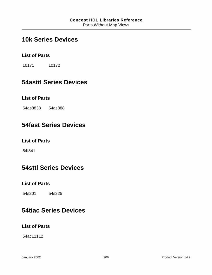
Concept HDL Libraries ReferenceParts Without Map Views
10k Series Devices
List of Parts
54asttl Series Devices
List of Parts
54fast Series Devices
List of Parts
54sttl Series Devices
List of Parts
54tiac Series Devices
List of Parts
10171 10172
54as8838 54as888
54f841
54s201 54s225
54ac11112
January 2002 206 Product Version 14.2
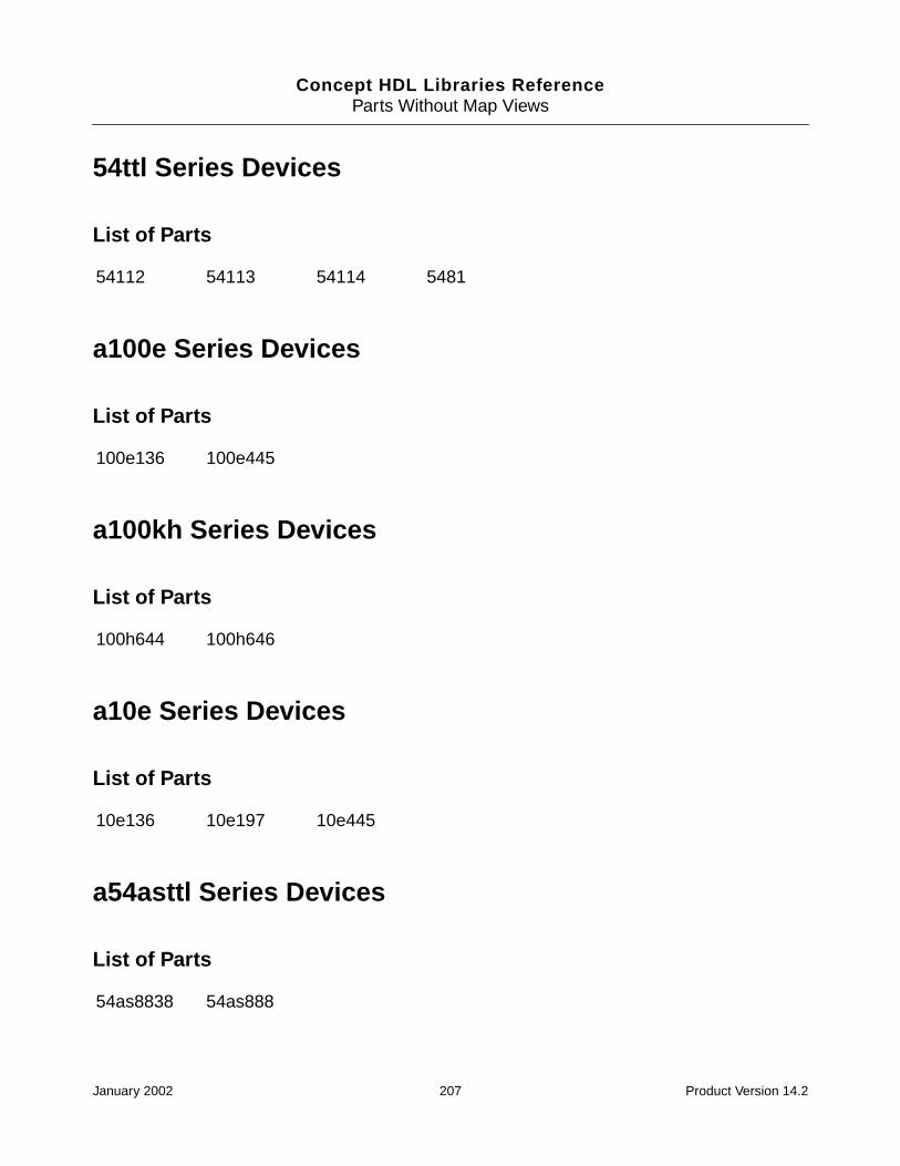
Concept HDL Libraries ReferenceParts Without Map Views
54ttl Series Devices
List of Parts
a100e Series Devices
List of Parts
a100kh Series Devices
List of Parts
a10e Series Devices
List of Parts
a54asttl Series Devices
List of Parts
54112 54113 54114 5481
100e136 100e445
100h644 100h646
10e136 10e197 10e445
54as8838 54as888
January 2002 207 Product Version 14.2
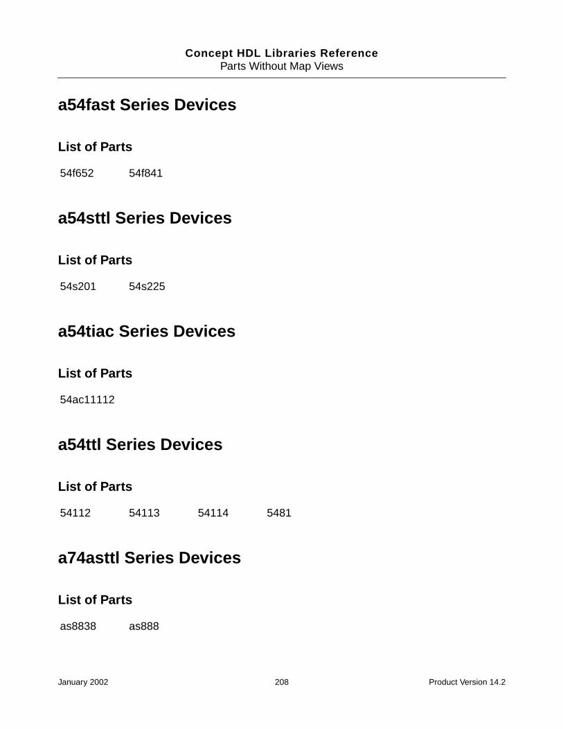
Concept HDL Libraries ReferenceParts Without Map Views
a54fast Series Devices
List of Parts
a54sttl Series Devices
List of Parts
a54tiac Series Devices
List of Parts
a54ttl Series Devices
List of Parts
a74asttl Series Devices
List of Parts
54f652 54f841
54s201 54s225
54ac11112
54112 54113 54114 5481
as8838 as888
January 2002 208 Product Version 14.2
Concept HDL Libraries ReferenceParts Without Map Views
a74fact Series Devices
List of Parts
a74fast Series Devices
List of Parts
a74sttl Series Devices
List of Parts
a74ttl Series Devices
List of Parts
acmos Series Devices
List of Parts
act190 act192 act8836 act8837
f552
s471
81
4000b 4007b 4009b 4010b
January 2002 209 Product Version 14.2
Concept HDL Libraries ReferenceParts Without Map Views
agaas Series Devices
List of Parts
ainterface Series Devices
List of Parts
amemory Series Devices
List of Parts
asttl Series Devices
List of Parts
vs8002
am7820 mt8952 scanpsc100f spt7814
27c512 am29f010 cy7c265#2d40 cy8c166#2d25
cy8c185#2d35 hm6716#2d2 hm6716#2d3 m5m23168
smj61cd16 smj61cd256l smj61cd256s smj61cd64
smj64c16 smj68ce16 tmm2089c tmm2089p#2d45
tms4461 tms44c257 upd488170
as8838 as888
January 2002 210 Product Version 14.2
Concept HDL Libraries ReferenceParts Without Map Views
atidttl Series Devices
List of Parts
cmos Series Devices
List of Parts
fact Series Devices
List of Parts
fast Series Devices
List of Parts
ttl_552 ttl_81 ttl_8838 ttl_888
4000b 4007b 4009b 4010b 4552b
act190 act192 act8836 act8837
f552
January 2002 211 Product Version 14.2
Concept HDL Libraries ReferenceParts Without Map Views
gaas Series Devices
List of Parts
interface Series Devices
List of Parts
memory Series Devices
List of Parts
vs8002
am7820 mt8952 scanpsc100f spt7814
am2169 am27ls191 am27ps191 am29705
b2210 b3210 bct2160 bct2163
bct2164 bct2165 bct2166 cy7c265#2d15
cy7c265#2d40 cy7c457 cy8c166#2d25 cy8c185#2d35
hm6716#2d2 hm6716#2d3 idt72215 idt72225
m5m23168 smj61cd16 smj61cd256l smj61cd256s
smj61cd64 smj64c16 smj68ce16 tms4461
tms44c257 upd488170
January 2002 212 Product Version 14.2

Concept HDL Libraries ReferenceParts Without Map Views
pld Series Devices
List of Parts
rcamos Series Devices
List of Parts
sttl Series Devices
List of Parts
tidttl Series Devices
List of Parts
epf81188#2d232 epf81188#2d240 epf8452#2d160pga
epf8452#2d160pqfp epf8452#2d84 epm7096#2d100
epm7096#2d68 epm7128#2d100 epm7128#2d160
ac352 ac353 ac377 ac378 ac379
act352 act353 act377 act378 act379
s471
ttl_552 ttl_81
ttl_8838 ttl_888
January 2002 213 Product Version 14.2
Concept HDL Libraries ReferenceParts Without Map Views
ttl Series Devices
List of Parts
vlsi Series Devices
List of Parts
81
70108h 70116h adsp1401 adsp1410 adsp3211
adsp3220 adsp3221 adsp8018 b2011 b3011
b3018 b3110 b3120 d21064 i82188
i82351 i82359 i8289 idt7381 intc300
mc68331 mc68440p mpg68030 nc53c80 ns32008
ns32016 ns32032 ns32081 ns32082 ns32201
ns32202 ns32332 ns32382 ns32532 ns32c016
ns32c032 ns32c201 tact1010 tact8818 tact8832
tact8841 tact8847 tdc1010 thct1010 tial6302
tias8840 tlc34058 upd70108 upd70116 wtl1164
wtl1165 wtl3332
January 2002 214 Product Version 14.2

Concept HDL Libraries Reference
CPin Types
Pin Type Function Property Value
ANALOG An analog pin is a passive pin. It istypically connected to a passivedevice. A passive device does nothave a source of energy. Forexample, a resistor lead is apassive pin.
PIN_TYPE=ANALOG
NO_LOAD_CHECK=BOTH
NO_IO_CHECK=BOTH
ALLOW_CONNECT=TRUE
BIDIR A BIDIR pin is a input/output pin. INPUT_LOAD=(-0.01, 0.01)
OUTPUT_LOAD=(1.0, -1.0)
BIDIRECTIONAL=TRUE
INPUT An input pin is one to which youapply a signal. For example, pins 1and 2 on the 74LS00 NAND gateare input pins.
INPUT_LOAD=(-0.01,0.01)
OUTPUT An output pin is one to which thepart applies a signal. For example,pin 3 on the 74LS00 NAND gate isan output.
OUTPUT_LOAD=(1.0, -1.0)
TS A tri-state pin has three possiblestates: low, high, and highimpedance. When it is in its highimpedance state, a tri-state pinlooks like an open circuit. Forexample, the 74LS373 latch has 3-state pins.
INPUT_LOAD=(-0.01, 0.01)
OUTPUT_LOAD=(1.0, -1.0)
OUTPUT_TYPE=(TS, TS)
January 2002 215 Product Version 14.2

Concept HDL Libraries ReferencePin Types
TS_BIDIR A tri-state bi-directional pin. Abidirectional pin is either an inputor an output. For example, pin 2on the 74LS245 bus transceiver isa bi-directional pin. The value atpin 1 (an input) determines theactive type of pin 2, as well asothers.
INPUT_LOAD=(-0.01, 0.01)
OUTPUT_LOAD=(1.0, -1.0)
BIDIRECTIONAL=TRUE
OUTPUT_TYPE=(TS, TS)
OC An open collector gate omits thecollector pull-up. Use an opencollector to make "wired-OR"connections between thecollectors of several gates and toconnect with a single pull-upresistor. For example, pin 1 on the74LS01 NAND gate is an opencollector gate.
OUTPUT_LOAD=(1.0, *)
OUTPUT_TYPE=(OC, AND)
OC_BIDIR An open collector bi-directionalpin.
INPUT_LOAD=(-0.01, 0.01)
OUTPUT_LOAD=(1.0, *)
BIDIRECTIONAL=TRUE
OUTPUT_TYPE=(OC, AND)
OE An open emitter gate omits theemitter pull-down. The appropriateresistance is added externally.ECL logic uses an open emittergate and is analogous to an opencollector gate. For example, theMC10100 has an open emittergate.
OUTPUT_LOAD=(1.0,*)
OUTPUT_TYPE=(OE, OR)
OE_BIDIR An open emitter bi-directional pin. INPUT_LOAD=(-0.01, 0.01)
OUTPUT_LOAD=(1.0, *)
BIDIRECTIONAL=TRUE
OUTPUT_TYPE=(OE, OR)
January 2002 216 Product Version 14.2

Concept HDL Libraries ReferencePin Types
POWER A power pin expects either asupply voltage or ground. Forexample, on the 74LS00 NANDgate, pin 14 is VCC and pin 7 isGND.
PIN_TYPE=POWER
NO_LOAD_CHECK=BOTH
NO_IO_CHECK=BOTH
ALLOW_CONNECT=TRUENot listed on POWER_PINSline of the chips.prt file.
NC A no-connect, pin-on-body pin. PIN_TYPE=NC
NO_LOAD_CHECK=BOTH
NO_IO_CHECK=BOTH
ALLOW_CONNECT=TRUENot listed on NC_PINS lineof chips.prt file
ANALOG An analog pin.
UNSPEC A pin with no specific function.This pin type is often used forconnectors.
NO_LOAD_CHECK =‘BOTH’
NO_IO_CHECK = ‘BOTH’
ALLOW_CONNECT =‘TRUE’
GROUND A ground pin. If the pin is in the bodysection
POWER_PINS =(GND:<pin number>);
GROUND_NETS = ‘<pinname>’;
If the pin is in the pin section
‘<pin name>’:
PIN_NUMBER =‘(<pin_number>)’
PINUSE = ‘GROUND’;
January 2002 217 Product Version 14.2
Concept HDL Libraries ReferencePin Types
January 2002 218 Product Version 14.2
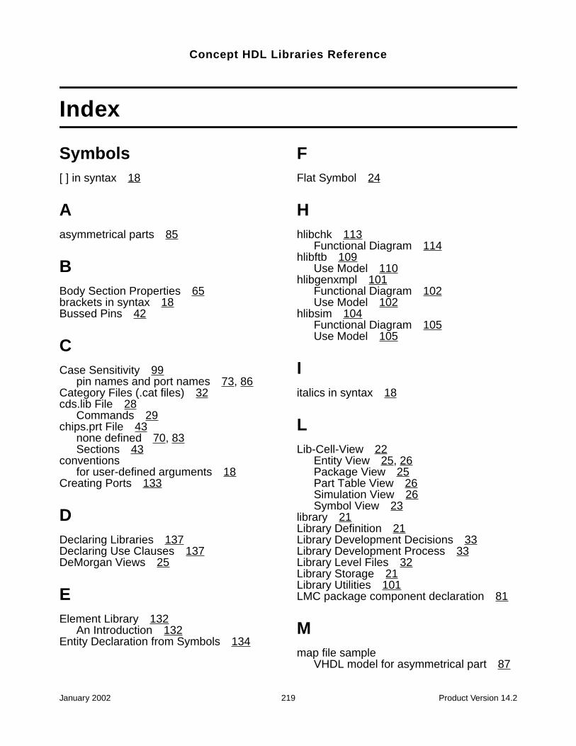
Concept HDL Libraries Reference
Index
Symbols[ ] in syntax 18
Aasymmetrical parts 85
BBody Section Properties 65brackets in syntax 18Bussed Pins 42
CCase Sensitivity 99
pin names and port names 73, 86Category Files (.cat files) 32cds.lib File 28
Commands 29chips.prt File 43
none defined 70, 83Sections 43
conventionsfor user-defined arguments 18
Creating Ports 133
DDeclaring Libraries 137Declaring Use Clauses 137DeMorgan Views 25
EElement Library 132
An Introduction 132Entity Declaration from Symbols 134
FFlat Symbol 24
Hhlibchk 113
Functional Diagram 114hlibftb 109
Use Model 110hlibgenxmpl 101
Functional Diagram 102Use Model 102
hlibsim 104Functional Diagram 105Use Model 105
Iitalics in syntax 18
LLib-Cell-View 22
Entity View 25, 26Package View 25Part Table View 26Simulation View 26Symbol View 23
library 21Library Definition 21Library Development Decisions 33Library Development Process 33Library Level Files 32Library Storage 21Library Utilities 101LMC package component declaration 81
Mmap file sample
VHDL model for asymmetrical part 87
January 2002 219 Product Version 14.2

Concept HDL Libraries Reference
VHDL model with sections 87VHDL model without sections 86
Map Views 26mapping
between pin names and port names 84Master.tag file 28multisection parts 71, 84
PPart Table File 46Physical Information Standards 64Pin Bubbles 38Pin Naming 39Pin Notes 40Pin Section Properties 64Pin Stubs 37Pin to Pin Spacing 38Pin Types 38Port Modes
Declaration 135Port Ranges
Declaration 137PORT_ORDER
property in VHDL map file 83Specifying 70
Preferred Parts 48Properties 41Properties for Generating Entity
Declarations from Symbols 134
SSchematic Part Symbols 35Signal Property in Chips View 45Sizeable Body 23Standard Library 127
CONN_BRK and CONN_GEN 127DEFINE 127, 128DRAWING 128FLAG 128GND_EARTH 128GND_SIGNAL 128GROUND 128MERGE/CONCAT 129NOT 130ORIGIN 130Pages 127PIN NAMES 130
REPLICATE 130SIGN EXTEND 131SIM_DIRECTIVES 131SLASH 131Taps 129VCC
132VCC_ARROW 132VCC_BAR 132VCC_CIRCLE 132VCC_WAVE 132
Standard Library Bodies 127Standards for Symbols (Body) 62SWIFT Models
With Sections 76Symbol Naming 42Symbol Notes 41Symbol Size 36Symbol Standards 62Symbol Versions 36syntax
port mapping 86
TTechnology Independent Libraries
FTB Flow 120Library Names 117The .cat File 118Views 119
Technology Independent PartsAccess 120
VVerilog Generic parameters
Declaration 135Verilog Map File 67
PRIMITIVE Section 68MODEL Section 69PIN MAP Section 71PROPERTY Section 69, 70
Verilog ModelAsymmetrical Parts 77
Verilog ModelsWith Sections 75
Verilog Type PortsDeclaration 136
Verilog Wrappers 77
January 2002 220 Product Version 14.2

Concept HDL Libraries Reference
Examples 78VHDL Generic parameters
Declaration 135VHDL Logic Type Ports
Declaration 136VHDL Map File 81
Examples 86Format 81LMC package component
declaration 81MODEL Section 83PIN MAP Section 84PRIMITIVE Section 82PROPERTY Section 83
VHDL ModelAsymmetrical Part 88
VHDL package 81VHDL Wrapper 89
Mapping Scenarios 90USE Clause 89VHDL Generics 89
January 2002 221 Product Version 14.2

Concept HDL Libraries Reference
January 2002 222 Product Version 14.2