Gavin McLachlan – [email protected] Randles Incorporated – randles.co.za

BPN ARCHITECTSGAVIN ORTON

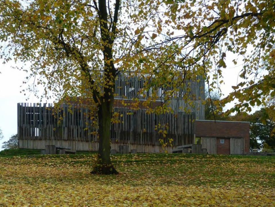
DARTMOUTH PARK PAVILIONPROJECT OVERVIEW
1. Brief development2. Concept Design3. Developed Design4. Technical Design5. Construction6. Post-construction

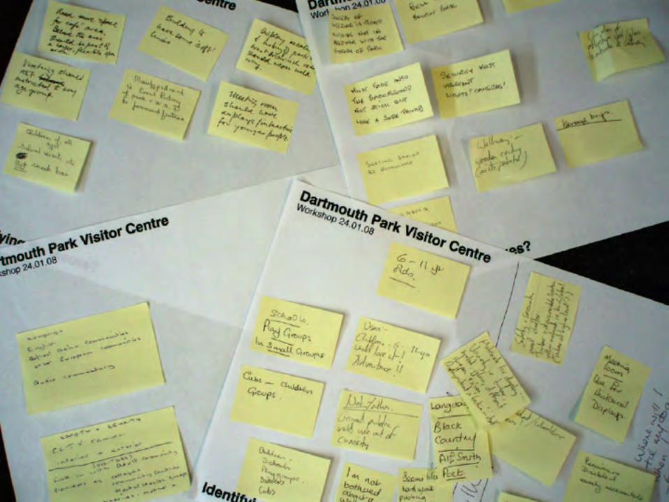
1. BRIEF DEVELOPMENT


The local community including residents, schools, groups and organisations


2. CONCEPT DESIGN

“Pythagoras of Samos was the first to fashion the letter Y into a pattern of human life. The straight portion at the bottom signifies the first, uncertain age, which at that point has been given over neither vices nor virtues. The bifurcation at the top, however, begins at adolescence. The path to the right is difficult, but it tends toward a blessed life. The path to the left is easier, but leads to ruin and destruction.”
Isidore of Serville (c.560-636 CE)

The Choice of Hercules
“…on the verge of manhood, he is contemplating his future when two women appear to him.
One, Vice, eager and seductive, shows him a path which seems to offer easy progress to a life of indolent pleasure. The other, tall and beautiful and identified as Virtue, warns Hercules that what is truly good can only be obtained through hard effort; and only then can Hercules gain supreme glory.”
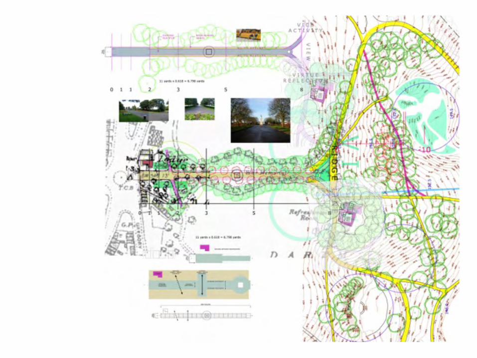


the programme


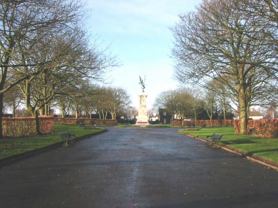
the woodland walk

the woodland walk

the woodland walk


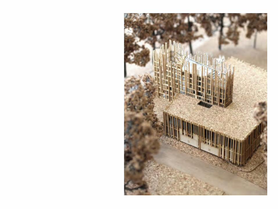
the tree house
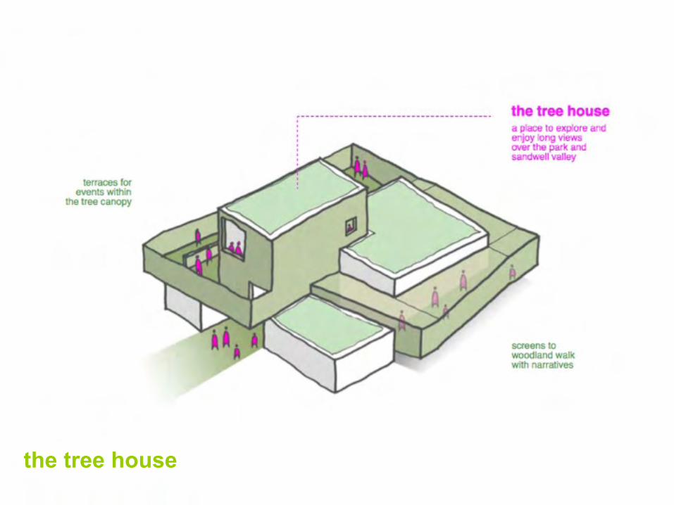
the tree house

3. DETAILED DESIGN

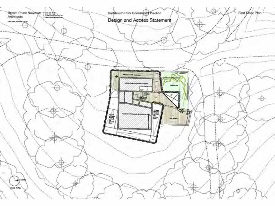
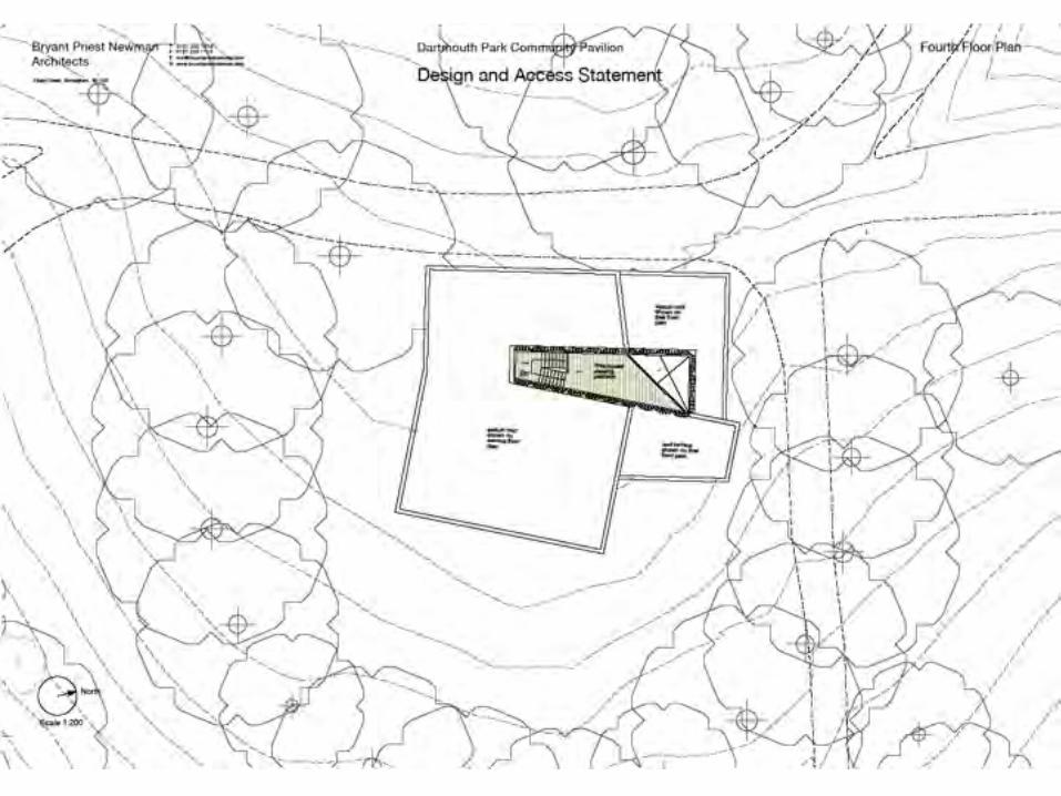


4. TECHNICAL DESIGN

04
161.200
S07
toiletsrefer to drawing 1770.2001 for details 160.200
t
fold
dow
nba
by c
hang
e
wash basinSD
Disabled W.C. (left handarrangement) / Baby
Change
Male W.C.
SD SD
light well over
communal wash area
HD
t
t
t
FemaleW.C.
100 2000 100 925
1690100 778
1000
100
100
900
100
bins / storage / plant
events roomrefer to drawing 1770.2038 for details
conc
eale
d dr
op d
own
proj
ectio
n sc
reen
disabledW.C.
(right hand arrangementN13/311)
store
store
boiler
vendingmachine
vendingmachine
power & mainsdrinking watersupply required forvending machines
roller shutterelectrical
equipment store
LANDING160.200
159.500
ramp 1 : 20500mm rise
159.520
S06
officerefer to drawing 1770.2036 for detailssnack bar
refer to drawing 1770.2035 for details
wall
mou
nted
tv
S05
foyer
additional storage above vending machines
void area underramp
ramp 1 : 20500mm rise
ramp 1 : 15330mm rise
ramp 1 : 15330mm rise
161.200159.500
159.500
160.200
160.050
161.200
projector recessed within suspended ceiling
wall mounted display cabinet
timberbench
Office a/c unitSnack Bar a/c unit Events room a/c unit
basinN13/331a
ENTRANCE LEVEL159.500
'slot
ted'
dra
inag
e ch
anne
ls in
floo
r. Ar
mte
c or
sim
ilar a
ppro
ved
beam and blockfloor construction
spaced to allow fordrainage channel
'slot
ted'
dra
inag
e ch
anne
l in fl
oor.
Arm
ocHe
x Dr
ain
or s
imila
r app
rove
d
RWP
AAV
SVP
SVP
SVP
RWP
1022.5
S04
159.500
HD
staff roomrefer to drawing 1770.2037 for details
stai
nles
s st
eel
mes
h to
clo
se o
ffvo
id a
rea
unde
rra
mp
D03(FD30s)
D04
D05(FD30s)
D06
D08(FD60s)
D09
D10
D11
D12
D13
D14(FD30s)
D15
D16
D17
D18(FD30s)
D19
W01
W03
W04
W05
W06
S01
S02S03
W02
Handrail centrallylocated on stair to
divide width
Cleaner'sstore
store
D07
RWP
W01
w.c., shower andstaff changing area
t
SVP RWP
D01(FD30s)
D02
4no. lockers
HD
high
leve
l she
lving
powe
r soc
kets
abo
ve d
esk
heig
ht
power sockets above desk height
plasterboard on timber battens with a skim coat and paint finish
stackable chair store
D20b D20a
stackable chair store
LANDING159.710
ramp 1 : 20210mm rise
ramp 1 : 20210mm rise
LANDING159.990 ramp 1 : 20
280mm rise
4 steps@170mm/rise
LANDING161.200
LANDING161.530
LANDING160.700
161.530
10 no. secure cycle spaces
refer to bpn drawing 1770.2058
dashed line indicates external trunking above
dashed line indicates external trunking above
2485 2000 2000 2000 2000 2000 2500 1700 2000 2000 2100
2100
2000
2100
1000
2000
2260
1000
2000
2000
1000
2000
2100
2100
2000
2000
2000
2000
2000
2000
2100
2100
2000
1300
2000
303
2000
1227.5
2485
3590
1585
1418
1115 1810 3497.5
5045
2300
1022.5
2915
1565 1585 2710
1902.5
4195
1810
2240
9091585
4000
10000
2000
5000
1585
2018
4715
49404397.51002.5
1115
1810
1340
3160
1564
.910
22.5
9658
7179
.5
175
3035
2270
3610
3
2
1
A CB D
826160504290
10340
1782
1810
2
10.0
0°
A
B
A
B
4
C
C
Facing brickworkF10/110, F10/110a
BlockworkF10/355
Softwood vertical timber board (100mm) lining with paint finishK21/160
FP
FP
FP
FB
FP
FP
FB
Fire point stand with 2.5kg carbon dioxide & 9 litre water and fire proceedure signage over
Fire blanket fitted to wall and fire proceedure signage over
brya
ntpr
iest
new
man
©. Do not scale off drawing. Check all dimensions on site and advise any discrepancies before commencing work. All figured dimensions are millimetres unless otherwise stated. Location plans subject to © Crown Copyright. dr = drawn by, ch = checked by
b r y a n t p r i e s t n e w m a n l t da r c h i t e c t s 3 m a r y s t r e e tb i r m i n g h a m B 3 1 U Dt : 0 1 2 1 2 3 3 1 8 1 8 f : 0 1 2 1 2 3 3 1 1 1 8w w w . b r y a n t p r i e s t n e w m a n . c o mm a i l @ b r y a n t p r i e s t n e w m a n . c o m
1:50 @A11:100@A3
C10drawing revision
scale date
revisions drawn by
checked by
Dartmouth Park Community Pavilion - West Bromwich
Ground Floor Plan
1770.1001
10.09
TD
LP
C1 - Construction issue - 110118 (dr TD/ch RS) C2 - Revisions as indicated - 110204 (dr GO/ch RS)C3 - Revisions as indicated + timber cladding profiles indicated - 110304 (dr MC/ch RS)C4 - Revisions as indicated - 110404 (dr MC/ch RS)
C5 - Revisions as indicated - 110608 (dr MC/ch RS)C6 - Revisions as indicated - 110614 (dr MC/ch RS)C7 - Revisions as indicated - 110616 (dr MC/ch RS)C8 - Revisions as indicated - 110819 (dr MC/ch RS)
C9 - Revisions as indicated - 110608 (dr MC/ch RS)C10 - FINAL CONSTRUCTION ISSUE - 111028
02
04
04
04
04
05
03
03
03
Identified construction hazard
01. Working within a park enviroment which will be partially open to the public.
Risk
Members of the public and particularly children moving in close proximity to site, and potentially attempting to enter site itself. Dangers associated with moving materials through populated park environment.
Potential construction hazards identified by Architect
02. It is understood that the remains of a former park pavilion building may be located below ground level on the site.
The full extent of this is unknown, There is a also a slight risk that there are old basements from the building and possibly services infastructure
Guidance
Risk assessment to be undertaken by contractor to establish safe strategy for securing site and transporting materials from the road to the site. Strategy to be developed and coordinated with wider park regeneration and SMBC Park's Manager.
Due care and attention to be paid whilst initial excavation works are carried out.
03. Handling and fixing of steel structure to tower, large lintels and steel beams. Risk of steel falling. Risks associated with working at height. Safe working procedures, exclsuion zones and risk assessments to be in place
04. Handling and fixing of large timber elements to ramped walkway that can not be safely carried / fixed by one indivdual. Also fixing of oversized timber elements at height.
Risk of timber falling, injuries due to carrying heavy items. Risk of falling from height.
05. Handling of large beam and block floor elements. Risk of large items falling and injuring construction workers.
06. Working in close proximity to existing trees. Restricted crane access/maneuverability due to proximity of trees, danger of collision with tree canopies.
Adequate protection of tree canopies and work to be carried out in accordance with BS 5837Debris falling from trees onto site.
07. Handling and fixing of large timber cladding elements to tower at height Risk of construction workers and/or large timbers falliing .
Risk assessments and method statement to the erectling of large timber section to ensure safe handling by operates within permissible manual handling limits
Ensure operatve have adequate PPE and appropriate working methods to protect against falling / injury
Risk assessments and method statement to the erectling of large timber section to ensure safe handling by operates within permissible manual handling limits. Timber to be designed to allow cranage where necessary
REFER TO EXTERNAL WORKS DRAWING 1770.1000 FOR DETAILS OF TERRACE AREA
REFER TO EXTERNAL WORKS DRAWING 1770.1000 FOR DETAILS OF ENTRANCE AREA
N

brya
ntpr
iest
new
man
©. Do not scale off drawing. Check all dimensions on site and advise any discrepancies before commencing work. All figured dimensions are millimetres unless otherwise stated. Location plans subject to © Crown Copyright. dr = drawn by, ch = checked by
b r y a n t p r i e s t n e w m a n l t da r c h i t e c t s 3 m a r y s t r e e tb i r m i n g h a m B 3 1 U Dt : 0 1 2 1 2 3 3 1 8 1 8 f : 0 1 2 1 2 3 3 1 1 1 8w w w . b r y a n t p r i e s t n e w m a n . c o mm a i l @ b r y a n t p r i e s t n e w m a n . c o m
1:50 @A11:100 @A3
C5drawing revision
scale date
revisions drawn by
checked by
Dartmouth Park Community Pavilion - West Bromwich
Section A-A
1770.1010
10.09
RS
LP
C1 - Construction issue - 110118 (dr TD / ch RS)C2 - General revisions throughout - 110304 (dr MC / ch RS)C3 - Revisions as indicated - 110314 (dr MC / ch RS)C4 - Revisions as indicated + detail removed from internal elevations to avoid confilcting information - 110408 (dr MC / ch RS)
C5 - FINAL CONSTRUCTION ISSUE - 111028
1st FFL 162.580(TOS 162.540)
2nd FFL 164.880(TOS 164.840)
3rd FFL 167.180 (TOS 167.140)
4th FFL 169.480(TOS 169.440)
159.500 entrance
3080
2300
2300
2300
1800
160.200 entrance landing
161.200 events space
171.280
161.200 161.200
161.950
163.460
165.325
164.805
timber cladding not shown for clarity. For timber cladding setting out see BPN drawings 1770.2021-2027
events roomfor details see BPN drawing 1770.2038
3225
159.500
160.560
161.910
163.700
162.580
2625
2625
159.500
'woodland walk'for cladding details see BPN drawing 1770.2020
snack barfor details see BPN drawing 1770.2035
officefor details see BPN drawing 1770.2036
'woodland walk'
160.1375
150
125
100
120
13
Aluminium coping
150mm minimum upstand above sedum to the underside of the aluminium coping
insulated cavity closer to the top of all cavity walls
12.5 mm plasterboard / acoustic plasterboard with taped and filled joints on metal frame system to create a 120mm service void for small power and small bore piped services and to enable linear light fittings to be recessed - refer to ceiling plan for detail of plaster finishes
concrete plank roof
plaster, skim coat and paint finish to walls
window frames - refer to separate window schedule for details
door, frame and architraves
Concrete plank roof
Cavity trays preformed cavity tray to the perimeter of the roof terrace - see adjacent specification
300
cavity insulation to overlap roof insulation by a minimum 300mm to minimise cold bridging
300
Metal deck to terrace - fixing details to be confirmed
ground bearing slab to structural engineers details
Hyload Original damp proof course at finished floor level and a minimum 150mm above adjoining ground level - DPC to inner leaf to be lapped and continuously sealed to below slab DPM
concrete cavity fill up to ground level and with 150mm of slab level
150
25mm thick perimeter insulationto the edge of the slab to minimise cold bridging
softwood vertical boarding with a painted finish on 25mm timber horizontal battens at max 400mm centres fixed to inner leaf of blockwork
Metal deck to roof terrace - fixing details to be confirmed
102 100 102
toiletsrefer to drawing 1770.2001 for details 160.200
t
fold
dow
nba
by c
hang
e
wash basin
SD
Cleaner'sstoreDisabled W.C. (left hand
arrangement) / BabyChange
Male W.C.
SD SD
light well over
communal wash area
HD
t
t
t
FemaleW.C.
100 100
100
100
100
100
basin
bins / storage / plant
events roomrefer to drawing 1770.2038 for details
conc
eale
d dr
op d
own
proj
ectio
n sc
reen
disabledW.C.
(right hand arrangementN13/311 )
store
store
boile
r
store
large vendingmachine700x920mm
large vendingmachine700x920mm
power & mainsdrinking watersupply required forvending machinesroller shutter
electricalequipment store
LANDING160.200
159.500
ramp 1 : 20500mm rise
159.520
S06
officerefer to drawing 1770.2036 for detailssnack bar
refer to drawing 1770.2035 for details
S05
foyer
timber bench
void area underramp
ramp 1 : 20500mm rise
ramp 1 : 15330mm rise
ramp 1 : 15330mm rise
161.200159.500
159.500
160.200
160.050
159.990
161.200161.200
6 steps@167mm/rise
stackable chair store
projector recessed within suspended ceiling
S07
timberbench
timberbench
Office a/c unitSnack Bar a/c unit Events room a/c unit
ENTRANCE LEVEL159.500
'slot
ted'
dra
inage
cha
nnel
s in
floo
r. Ar
mte
c or
sim
ilar a
ppro
ved
'slot
ted'
dra
inage
cha
nnel
in fl
oor.
Arm
tec
or s
imila
r app
rove
d
RWP
AAV
SVP
SVP
SVP
RWP
RWP
S04
159.500
raised section of timber bench to form back rest
HD
w.c., shower andstaff changing area
staff roomrefer to drawing 1770.2037 for details
t
SVP RWP
stai
nles
s st
eel
mes
h to
clo
se o
ffvo
id a
rea
unde
rra
mp
D01
D02
D03
D04
D05
D06
D07(FD30s)
D08
D09
D10
D11
D12
D13
D14(FD30s)
D15(FD30s)
D16
D17
D18
D19
D20
W01
W03
W04
W05
W06
S01
S02S03
W02
4no. lockers
LANDING159.710
ramp 1 : 20210mm rise
ramp 1 : 20210mm rise
LANDING159.990 ramp 1 : 20
280mm rise
4 steps@170mm/rise
LANDING161.200
LANDING161.530
LANDING160.700
161.530
2485
2000
9658
7179
.5A
B
A
BE E
C
C
D
D
Section A-A
Preformed weep holes
Beak weep by Cavity Trays of Yeovil, Somerset, BA22 8HU. (01935 474769). Build into perp joints over lintels, trays and DPCs at 450mm centres.
Installation/site work - Position in perp on DPC, in accordance with manufacturers instructions. Spacing at 450mm centres in accordance with NHBC andBRE recommendations.
Cavity Trays
Type P cavitray from Cavity Trays of Yeovil, Somerset. BA228HU (01935) 474769. Lay preformed Type P parapet cavitray lengths and angles within appropriate mortar bed as work proceeds.
Glove lap and seal adjoining lengths. Incorporate roof lead flashing to detail. Observe accompanying fitting instructions at all times.
Apron flashings
Ubiflex non-lead flashing by Ubbink (UK) Ltd. Borough Road, Brackley, Northants NN13 7TB Tel: 0845 456 3499
When installing with DPC / Cavity Tray Ubiflex should be installed at the same time, the Ubiflex should be fitted to a depth of not less than 50mm with the edge turned back into a single welt to anchor it into the mortar. Ubiflex should then be held in place with Ubiflex fixing clips, spaced not more than 450mm apart and then the joint filled with Ubiflex Gap-Seal
Ubiflex should cover the upstand by at least 75mm and be sealed to it with a continuous bead of High-Tack sealant. The height of the upstand should be at least 150mm. Overlap joints of 150mm are required in all flashings and must be sealed with Ubiflex High-Tack.
steel angle with pre-drilled holes (85mm centres) fixed back to UB to S.E. specification
steel angle with pre-drilled holes (85mm centres) fixed back to UB to S.E. specification
position of metal floor planks where appropriate
Steelwork to S.E. details
Oak cladding piece coach bolted back to steel angles
Oak cladding piece coach bolted back to steel angles
SECTION 1
steel angle with pre-drilled holes (85mm centres) fixed back to UB to S.E. specification
steel angle with pre-drilled holes (85mm centres) fixed back to UB to S.E. specification
position of metal floor planks where appropriate
Steelwork to S.E. details
Oak cladding piece coach bolted back to steel angles
Oak cladding piece coach bolted back to steel angles
SECTION 2
162.580 First floor terrace
164.880 Second floor
167.180 Third floor
169.480 Fourth floor
thick line denoting parapet / roof level of brick accomodation blocks below
Detail 2
Detail 1
thick line denoting parapet / roof level of brick accomodation blocks below
14270
6250
875
2290
3065
8260
1655
2290
2290
1990
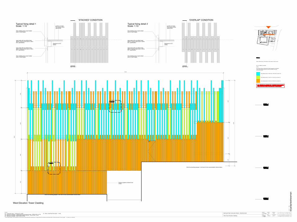
Feature graphics stained onto timber
S12
brick pavers
Timber deck laid onto brick plinth
159.500t e r r a c e ramped
d o w n to meet path
t e r r a c e level withg rass
159.500
160.315
159.650
159.800
159.950
160.150
Timber decked seating area
timber decked terrace
Brick pavers to match foyer
toilets160.200
fold
do
wn
baby
ch
ange
w a s h basin
S D
Cleaner 'ss t o r eD i s a b l e d W.C. (left hand
a r rangemen t ) / BabyC h a n g e
Male W. C.
S D S D
roof l ighto v e r
c o m m u n a l wash area HD
bin &storagea b o v e
t
t
t
Fema leW. C.
1 0 0 2 0 0 0 1 0 0 9 2 5
1 6 9 01 0 0 7 7 8
1 0 0 0
100
1 0 0
1300
1 0 0
b a s i n
bins / storage / plant
events room
conc
eale
d dr
op
dow
n pr
ojec
tion
scre
en
t i m b e r bench seating around perimeter
d isabled W. C.( r i g h t hand
a r rangemen t )
s t o r e
s t o r e
boi ler
s t o r e
l a r g e vendingmach ine7 0 0 x 9 2 0 m m
l a r g e vendingmach ine7 0 0 x 9 2 0 m m
p o w e r & ma insd r i n k i n g watersupp ly required forv e n d i n g machinesr o l l e r shutter
e lec t r ica le q u i p m e n t store
LANDING160.200
159.500
ramp 1 : 20500mm rise
159.520
p ivo ted oak doort o match timber
s c r e e n
o a k door to matcht i m b e r screen
office
snack bar hi g
h le
vel
shel
ving
ba
r co
unte
r
b in /c leaning
storage
hig
h le
vel
coun
ter
with
sh
elvi
ng wal
l /
cupb
oard
do
ors
with
m
agne
tic w
hite
bo
ard
finis
h
wal
lm
o un t
e d tv
d i s h w a s h e r
wal
l m
ount
ed
i ns e
c t k
iller
hand-w a s h
stor
age
/c o
a ts
etc
s torage
CC
TV
mon
itors
po
we
r so
cket
s ab
ove
tab l
e he
ight
s a f e withshelvesa b o v e
ga l van i sedsteel
s e c u r i t ys c r e e n
s t a b l e door
ga l van i sedsteel
s e c u r i t ys c r e e n
foyer
b e n c h &c o a t
h o o k s
b a s i na n d
m i r r o r
tea po in t
fullh e i g h tl o c k e r
fullh e i g h tl o c k e r
fullh e i g h tl o c k e r
2 x halfh e i g h tl ocke rs
fr idge
storage
storage
b i n s /c leaning
c o a th o o k sf o r wet
c l o t hes /boo t s
w . c. and staffchang ing area
staff room
b e n c h
add i t i ona l storage above vending machines
t i m b e r bench / display unit
v o i d area underr a m p
ramp 1 : 20500mm rise
ramp 1 : 1 5330mm rise
ramp 1 : 1 5330mm rise
161.200
159.500159.500
159.500
160.200
160.050 159.990
tim
ber
benc
h se
a tin
g ar
o und
pe
rimet
er
161.200161.200
6 steps @ 167mm/rise
s t a c k a b l e chair store
ed
ge
of
boxe
d ou
t be
am
ove r
head
p r o j ec to r r ecessed within suspended ce i l ing
l o w e r timber bench / step
+ 5 0 0 m m
+ 2 5 0 m m
steel security gate
fridge
hot dr inksm a k e r
ch i l ledd i s p l a ycab ine t withstorageb e l o w
storageb e l o wcounter
cash register
a c c e s s
mic
ro- w
av e
g lazed display cabinetb u i l t into wall
slid
ing
win
dow
s l id ing window
t i m b e rb e n c h
t i m b e rb e n c h
O f fi c e a/c unitS n a c k Bar a/c unit E v e n t s room a/c unit
drai
nage
ch
anne
l in
floo
r be
l ow
pivo
ted
door
d r a i n a g e channel in floor
b a s i n
t i m b e rb e n c h
t i m b e rb e n c h
ENTRANCE LEVEL159.500
LANDING159.710
ramp 1 : 20210mm rise
ramp 1 : 20210mm rise
LANDING159.990 ramp 1 : 20
280mm rise
4 steps @ 170mm/rise
LANDING161.200
LANDING161.530
LANDING160.700
161.530
brya
ntpr
iest
new
man
©. Do not scale off drawing. Check all dimensions on site and advise any discrepancies before commencing work. All figured dimensions are millimetres unless otherwise stated. Location plans subject to © Crown Copyright. dr = drawn by, ch = checked by
b r y a n t p r i e s t n e w m a n l t da r c h i t e c t s 3 m a r y s t r e e tb i r m i n g h a m B 3 1 U Dt : 0 1 2 1 2 3 3 1 8 1 8 f : 0 1 2 1 2 3 3 1 1 1 8w w w . b r y a n t p r i e s t n e w m a n . c o mm a i l @ b r y a n t p r i e s t n e w m a n . c o m
1:25 @A11:50 @A3
C5drawing revision
scale date
revisions drawn by
checked by
Dartmouth Park Community Pavilion - West Bromwich 1770.2025
07.10
TD
LPWest Tower Elevation Cladding
C1 - Construction issue - 110118 (dr TD / ch RS)C2 - Revisions as indicated + cladding quantities and spacing revised - 110304 (dr MC / ch RS)C3 - Revisions as indicated + painted feature graphics removed - 110613 (dr MC / ch RS)C4 - Revisions as indicated - 110617 (dr MC / ch RS)
C5 - FINAL CONSTRUCTION ISSUE - 111028
Typical fixing detail 1 Scale: 1:10
West Elevation Tower Cladding
Typical fixing detail 2Scale: 1:10
'STACKED' CONDITION 'OVERLAP' CONDITION
Notes:
Refer to BPN drawing 1770.2020 for further details of timber screen
KEY TO TIMBER CLADDING
NOTE:
Any treated surfaces of large section timbers exposed by unavoidable cross cutting should be liberally brushed with ENSELE end grain preservative solution.
Oak cladding element. 100mm (D) x 75mm (W) x as drawn (H).
Oak cladding element. 75mm (D) x 75mm (W) x as drawn (H).
Oak cladding element. 50mm (D) x 75mm (W) x as drawn (H).
ALL TIMBER CLADDING TO TOWER TO BE GREEN OAK WITH NO FIRE PROTECTION TREATMENT
FINAL CONSTRUCTION ISSUE

Wall Finishes
Exposed blockwork with masonry paint finish - paint colour tbc (F10/355) Exposed brickwork (F10/110) T&G, square edge, softwood lining with 'Arch Chemicals' - 'Dricon' fire retardency
and eggshell paint finish - paint colour tbc Plasterboard, skim and paint - paint colour tbc
Floor Finishes
Brick pavers (F10/110a)
Marmoleum (Product: Walton uni or cirrus range, 2m sheets with welded joints)
400
2500
boiler to mechanical engineers spec
wall mounted fold down baby change unit
brickwork beyond
blockwork beyond
Female W.C.
Disabled W.C.
Male W.C.
Store
exposed blockwork walls to be painted
Gyproc Wallboard on MF system with a clear service void above.
brickwork beyond brickwork beyondFemale W.C.
Male W.C.
Store
1960
100
D08 D10
SD SD SD
brickwork beyond brickwork beyond
blockwork beyond
Wash area
recess in suspended ceiling with feature lighting (detail tbc)
800
275
D10 D08
painted softwood lining
painted softwood lining
TP
ARPTSDHD2500
brickwork beyond
blockwork beyond
Disabled W.C.
Gyproc Wallboard on MF system with a clear service void above
painted softwood lining
brickwork beyond
blockwork beyond
Male W.C.Wash area
painted softwood lining
TP
AR PT SD HD
blockwork beyond
Female W.C.
Disabled W.C.
exposed blockwork walls to be painted
D11D12D13
100mm marmoleum upstand
2400
service void
HD HD
blockwork beyond
Male W.C. Wash area
recess in suspended ceiling with feature lighting
2135
1100
800
2500
painted softwood lining
Disabled W.C.
exposed blockwork walls to be painted
Gyproc Wallboard on MF system with 120mm clear void above to allow for services and light fittings.
light well over
communal wash area
disabledW.C.
(right hand arrangement
N13/311) store
boiler
Office a/c unitSnack Bar a/c unit Events room a/c unit
SVP
RWP
RWP
D16
Cleaner'sstore
FemaleW.C.
toilets
t
fold
dow
nba
by c
hang
e
wash basinSD
Disabled W.C. (left handarrangement) / Baby
Change
Male W.C.
SD SD
t
t
t
2000 100
925 1687 100 778100
889
100
D8
D9
D10
D11
D12
D13
410
488
HD
HD
1000
2300
100 2077 128 900
1120
1695
705103036418201000
100
753
100
753
100
753
100
322
100
753
709
359
2200
925
1285
BoilerRoom
1498
1285
2200
600x600access hatch
600x600access hatch
150
150
==
600
B
AA
B
C
C
DD
E
E
F F
GG
H
H
brya
ntpr
iest
new
man
©. Do not scale off drawing. Check all dimensions on site and advise any discrepancies before commencing work. All figured dimensions are millimetres unless otherwise stated. Location plans subject to © Crown Copyright. dr = drawn by, ch = checked by
b r y a n t p r i e s t n e w m a n l t da r c h i t e c t s 3 m a r y s t r e e tb i r m i n g h a m B 3 1 U Dt : 0 1 2 1 2 3 3 1 8 1 8 f : 0 1 2 1 2 3 3 1 1 1 8w w w . b r y a n t p r i e s t n e w m a n . c o mm a i l @ b r y a n t p r i e s t n e w m a n . c o m1:50 @A1
C6drawing revision
scale date
revisions drawn by
checked by
Dartmouth Park Community Pavilion - West Bromwich
Toilet Details - Plan / Elevation
1770.2001
07.04.10
MC
LP
C1 - Construction issue - 110118 (dr TD / ch RS)C2 - General revisions - 110404 (dr MC / ch LP)C3 - General revisions - 110613 (dr MC / ch LP)C4 - Dimensions added to toilet layout - 110803 (dr GO / ch LP)
C5 - Access hatch shown on plan - 110819 (dr MC / ch LP)C6 - FINAL CONSTRUCTION ISSUE - 111028
Elevation A Elevation B Elevation C
Elevation D Elevation E Elevation F
Elevation G Elevation H
Toilet roll dispenser:to Williams Ironmongery schedule
Coat hook:to Williams Ironmongery schedule
Room / Fitting
Male WC
Female WC
WCs Washbasins
Wall mounted urinal by Armitage Shanks from the Contour range or similarN13/315a
Urinals
N/A
Wall mounted WC by Armitage Shanks from the Braemar range or similar. Colour: WhiteN13/300b
Taps
Wall mounted WC by Armitage Shanks from the Braemar range or similar. Colour: WhiteN13/300b
N/A
Accessories
N/A
N/A
Wall mounted stainless steel wash trough.N13/346
Hand washarea
N/AN/A Contour 21 Basin mixer by Armitage Shanks.
Soap dispenser:to Williams Ironmongery schedule
Semi recesssed Velocity high speed hot air hand dryer by Dolphin - satin stainless steelN13/472a
N/A Toilet roll dispenser:to Williams Ironmongery schedule
Coat hook:to Williams Ironmongery schedule
Standard doc M packN13/311
Disabled WC N/AStandard doc M packN13/311
Standard doc M packN13/311
Standard doc M packN13/311
Baby changing unitN13/449a
Armitage Shanks 310mm Alder sinkN13/331a
Cleaners Store N/AN/A N/A N/A
IPS
Armitage Venesta Tough Wall system with solid laminate access panels
Armitage Venesta Tough Wall system with solid laminate access panels
N/A
N/A
N/A
light well over
communal wash area
disabledW.C.
(right hand arrangement
N13/311) store
boiler
Office a/c unitSnack Bar a/c unit Events room a/c unit
SVP
RWP
RWP
D16
Cleaner'sstore
FemaleW.C.
toilets
t
fold
dow
nba
by c
hang
e
wash basinSD
Disabled W.C. (left handarrangement) / Baby
Change
Male W.C.
SD SD
t
t
t
2000 100
925 1687 100 778100
889
100
D8
D9
D10
D11
D12
D13
410
488
HD
HD
1000
2300
100 2077 128 900
1120
1695
705103036418201000
100
753
100
753
100
753
100
322
100
753
709
359
2200
925
1285
BoilerRoom
1498
1285
2200
600x600access hatch
600x600access hatch
150
150
==
600
10010
10010
Timber lining details1:5
MF suspended ceiling
stud wall
T&G square edge softwood lining with paint finish
stud wall fixed through DPM
10mm shadow gap to top and bottom of lining
10mm shadow gap to top and bottom of lining

brya
ntpr
iest
new
man
©. Do not scale off drawing. Check all dimensions on site and advise any discrepancies before commencing work. All figured dimensions are millimetres unless otherwise stated. Location plans subject to © Crown Copyright. dr = drawn by, ch = checked by
C1 - Initial construction issue - 110805C2 - Revisions as indicated - 111017C3 - FINAL CONSTRUCTION ISSUE - 111028
b r y a n t p r i e s t n e w m a n l t da r c h i t e c t s 3 m a r y s t r e e tb i r m i n g h a m B 3 1 U Dt : 0 1 2 1 2 3 3 1 8 1 8 f : 0 1 2 1 2 3 3 1 1 1 8w w w . b r y a n t p r i e s t n e w m a n . c o mm a i l @ b r y a n t p r i e s t n e w m a n . c o m
DARTMOUTH PARK PAVILION | WEST BROMWICH
1:25 @ A3
1770.2058
06.2011
MC
GOFOYER STAIT BALUSTRADE DETAIL
C3drawing revision
scale date
revisions drawn by
checked by
1290300
handrail to have 300mm minimum overun
SHS post to SE specification
Galvanised steel plate
18x150 oak patress following gradient of stair
75x75 green oak sections @ 140mm centres fixed to internal face of galvanised plate
10mm galvanised string at handrail level to SE specification
Galvanised steel plate fixed concrete sub base (to SE details) before brick pavers are laid over
75x75mm timber sections
Galvanised steel plate
timber handrail fixed to 18x150mm oak patress
Steel column
Galvanised steel plate fixed concrete sub base (to SE details) before brick pavers are laid over
251150
75x75mm hollow steel section
TYPICAL ELEVATION A
TYPICAL ELEVATION B
PLAN
primary structure timber cladding
timber handrail
1150
950
EXPLODED AXONOMETRIC

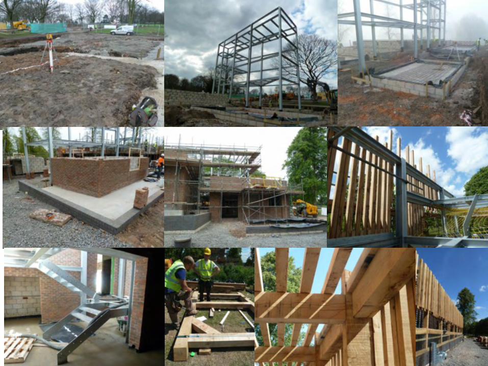
5. CONSTRUCTION


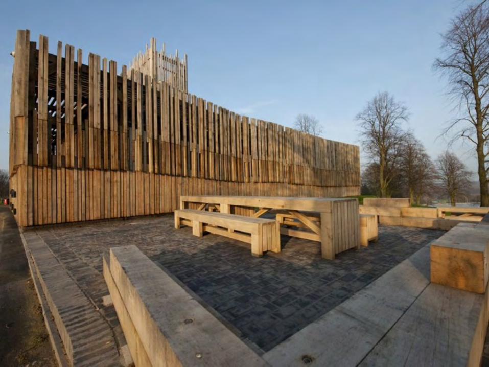


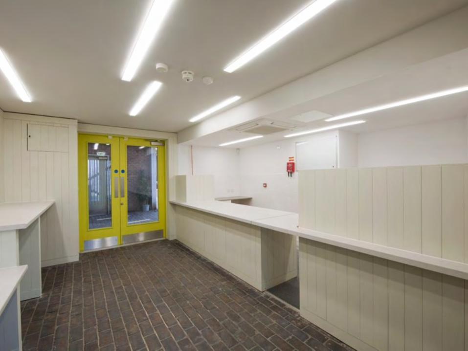


6. POST-CONSTRUCTION


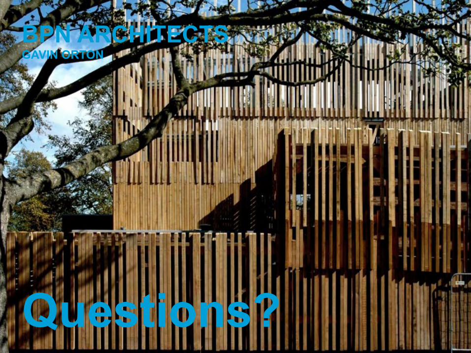
BPN ARCHITECTSGAVIN ORTON
Questions?