
CONCENTRATING SOLAR POWER PHOENIX, … · Sulfur Based Thermochemical Energy Storage for Solar...
136
APRIL 23–25, 2013 PHOENIX, ARIZONA CONCENTRATING SOLAR POWER PROGRAM REVIEW 2013
Transcript of CONCENTRATING SOLAR POWER PHOENIX, … · Sulfur Based Thermochemical Energy Storage for Solar...
APRIL 23–25, 2013 PHOENIX, ARIZONA
CONCENTRATING SOLAR POWERPROGRAM REVIEW 2013

SunShot Concentrating Solar Power Program Review 2013
WelcomeDear Colleague:
On behalf of the U.S. Department of Energy (DOE) SunShot Initiative, it is my pleasure to welcome you to the SunShot Concentrating Solar Power (CSP) Program Review 2013.
The SunShot Initiative was launched in 2011 as a national collaborative effort aimed at addressing an aggressive cost reduction goal for solar-generated electricity to achieve grid parity without subsidy by the end of the decade. Since October 2011, the SunShot CSP Program has committed over $130M to new funding initiatives for CSP technologies. Combined with the awards continuing from prior funding opportunities, the Program maintains an appropriately balanced portfolio of projects at industry, national laboratories
and universities developing technologies for the near-, mid- and long-terms.
The Program Review features presentations by DOE awardees working at the forefront of research, development, and demonstration towards reducing costs and increasing performance of CSP technologies. The Review also brings together a broad base of external stakeholders to engage in and contribute to the deployment of the CSP technologies being developed under the SunShot Initiative.
Plenary sessions on each day of the meeting include keynote talks that offer broad perspectives on topics ranging from quantifying the value of CSP and thermal energy storage, presented through grid integration analysis as well as from the vantage of a utility company, to global projects and opportunities for CSP from an international financing viewpoint. Complementing the keynote presentations are highlight talks featuring three recently graduated projects from the portfolio that have leveraged successful technology developments with DOE funding and continued the momentum towards commercialization.
It is an exciting time for CSP, with tremendous activity building up worldwide as many countries invest in CSP systems as part of their sustainable energy infrastructure. In the U.S., several large-scale commercial CSP plants are poised to be commissioned beginning in 2013 that will collectively more than triple the current capacity. As a culminating event of the Program Review, attendees will have a unique opportunity to witness a part of this growth through a tour of the Abengoa Solana Generating Station, a 280 MW parabolic trough plant with six hours of thermal energy storage—one of the brand new CSP plants revving up to contribute to the nation’s renewable energy portfolio.
Your participation greatly enhances the success of the Program Review, and I invite you to have engaging discussions with the attendees—be it for networking, seeding collaborative ventures or providing technical feedback.
With best wishes,
Ranga Pitchumani Director, Concentrating Solar Power SunShot Initiative

SunShot Concentrating Solar Power Program Review 2013
i
Schedule of EventsTuesday, April 23, 2013 . . . . . . . . . . . . . . . . . . . . . . . . . . . . . . . . . . . . . . . . . . . . . . . . . . . . . . . . . . . . . . . . . . . . . . . . . . . . . . . . .1Wednesday, April 24, 2013 . . . . . . . . . . . . . . . . . . . . . . . . . . . . . . . . . . . . . . . . . . . . . . . . . . . . . . . . . . . . . . . . . . . . . . . . . . . . . .2Thursday, April 25, 2013 . . . . . . . . . . . . . . . . . . . . . . . . . . . . . . . . . . . . . . . . . . . . . . . . . . . . . . . . . . . . . . . . . . . . . . . . . . . . . . . .3
Speaker BiographiesKeynote Speakers . . . . . . . . . . . . . . . . . . . . . . . . . . . . . . . . . . . . . . . . . . . . . . . . . . . . . . . . . . . . . . . . . . . . . . . . . . . . . . . . . . . . .4Highlight Presentation Speakers. . . . . . . . . . . . . . . . . . . . . . . . . . . . . . . . . . . . . . . . . . . . . . . . . . . . . . . . . . . . . . . . . . . . . . . . . .5
Keynote Presentation AbstractsQuantifying the Value of CSP with Thermal Energy Storage, P. Denholm and M. Mehos . . . . . . . . . . . . . . . . . . . . . . . . . . . . . . . .6Financing CSP Projects in Emerging Markets: A Perspective from the World Bank Group, D. Younger . . . . . . . . . . . . . . . . . . . . . . .7Integrating CSP with TES into a Utility System, B. Albert . . . . . . . . . . . . . . . . . . . . . . . . . . . . . . . . . . . . . . . . . . . . . . . . . . . . . . . . .8
Highlight Presentation AbstractseSolar’s Modular and Scalable Baseload Molten Salt Plant Design and Feasibility Project, C. Tyner and D. Wasyluk. . . . . . . . . . . . . . .9Polymeric Mirror Films: Durability Improvement and Implementation in New Collector Designs, R. Padiyath, E. Peterson, and D. Chen . . . . . . . . . . . . . . . . . . . . . . . . . . . . . . . . . . . . . . . . . . . . . . . . . . . . . . . . . . . . . . . . . . . . . . . . . . . . . . . . . . . . . . . . 11A New Generation of Parabolic Trough Technology, H. Price, P. Marcotte, K. Biggio, K. Manning, and D. Arias . . . . . . . . . . . 13
Thermal Receivers: Supercritical Carbon Dioxide and Molten Salt (Tuesday, 10:15 am – 12:15 pm, Kiva C)High-Efficiency Low-Cost Solar Receiver for Use in a Supercritical-CO2 Recompression Cycle, S. Sullivan, E. Vollnogle, J. Kesseli, and J. Nash . . . . . . . . . . . . . . . . . . . . . . . . . . . . . . . . . . . . . . . . . . . . . . . . . . . . . . . . . . . . . . . . . . . . . . . . . . . . . . . . . . . . . . . . . 15Direct s-CO2 Receiver Development, M. Wagner, Z. Ma, J. Martinek, T. Neises, and C. Turchi . . . . . . . . . . . . . . . . . . . . . . . . . 17High Flux Microchannel Receiver Development with Adaptive Flow Control, M. Drost, R. Wegeng, S. Apte, and V. Narayanan. . . . . 19Advanced Low-Cost Receivers for Parabolic Troughs, J. Stettenheim, T. McBride, O. Brambles, P. Magari , B. Davis, M. Iveson, W. Chen, R. Kaszeta, N. Kattamis, and C. Cheng. . . . . . . . . . . . . . . . . . . . . . . . . . . . . . . . . . . . . . . . . . . . . . . . . . . . . . . . . . 21
Thermal Storage and Heat Transfer Fluids: Thermochemical (Tuesday, 10:15 am – 12:15 pm, Pueblo)Sulfur Based Thermochemical Energy Storage for Solar Power Tower, B. Wong, L. Brown, R. Buckingham, D. Thomey, M. Roeb, and C. Sattler . . . . . . . . . . . . . . . . . . . . . . . . . . . . . . . . . . . . . . . . . . . . . . . . . . . . . . . . . . . . . . . . . . . . . . . . . . . . . . . 23Chemically Reactive Working Fluids for the Capture and Transport of Concentrated Solar Thermal Energy for Power Generation, R. Brotzman, M. Urgun-Demirtas, and J. Libera . . . . . . . . . . . . . . . . . . . . . . . . . . . . . . . . . . . . . . . . . . . . . . . . . . . . . . . . . . 25Low-Cost Metal Hydride Thermal Energy Storage System for Concentrating Solar Power Systems, R. Zidan, T. Motyka, B. Hardy, J. Teprovich, D. Knight, B. Peters, C. Corgnale, and C. Buckley . . . . . . . . . . . . . . . . . . . . . . . . . . . . . . . . . . . . . . . . . . . . . . 27Reversible Metal Hydride Thermal Energy Storage for High Temperature Power Generation Systems, E. Rönnebro, G. Whyatt, M. Powell, K. Simmons, Z. Fang, and R. White . . . . . . . . . . . . . . . . . . . . . . . . . . . . . . . . . . . . . . . . . . . . . . . . . . . . . . . . . . . 29
Power Cycles and Thermal Receivers: Hybrid and Air Brayton (Tuesday, 1:15 pm – 3:30 pm, Kiva C)Integrated Solar Thermochemical Reaction System for the High Efficiency Production of Electricity, R. Wegeng, D. Brown, R. Diver, P. Humble, J. Mankins, D. Palo, B. Paul, and W. TeGrotenhuis . . . . . . . . . . . . . . . . . . . . . . . . . . . . . . . . . . . . . . . . . . . . . . . 31Micromix Combustor for High Temperature CSP Air Brayton Cycle Systems, K. Brun and S. Coogan. . . . . . . . . . . . . . . . . . . . . . 33A Small Particle Solar Receiver for High Temperature Brayton Power Cycles, F. Miller, A. Hunt, and M. McDowell . . . . . . . . . . . 35Brayton-Cycle Baseload Power Tower CSP System, B. Treece and B. Anderson . . . . . . . . . . . . . . . . . . . . . . . . . . . . . . . . . . . . . . . 37Novel Dry Cooling Technology for Power Plants, C. Martin and J. Pavlish . . . . . . . . . . . . . . . . . . . . . . . . . . . . . . . . . . . . . . . . . . . 39
Table of Contents

SunShot Concentrating Solar Power Program Review 2013
ii
Power Cycles: Supercritical Carbon Dioxide and Solid State (Tuesday, 1:15 pm – 3:30 pm, Pueblo)10-MW Supercritical-CO2 Turbine Test, C. Turchi, T. Held, J. Pasch, and K. Gawlik . . . . . . . . . . . . . . . . . . . . . . . . . . . . . . . . 41Development of a High Efficiency Hot Gas Turbo-Expander and Low Cost Heat Exchangers for Optimized CSP Supercritical-CO2 Operation, J. Moore, K. Brun, P. Bueno, C. Kalra, D. Hofer, and J. Davis . . . . . . . . . . . . . . . . . . . . . . . . . . . . . . . . . . . . . . . . . . . 43Next-Generation Thermionic Solar Energy Conversion, N. Melosh, Z. X. Shen, and K. Littau . . . . . . . . . . . . . . . . . . . . . . . . . . 45Concentrated Solar Thermoelectric Power, G. Chen, Z. F. Ren, K. McEnaney, D. Kraemer, L. Weinstein, S. Boriskina, Q. Jie, T. Dahal, F. Cao, and W. S. Liu . . . . . . . . . . . . . . . . . . . . . . . . . . . . . . . . . . . . . . . . . . . . . . . . . . . . . . . . . . . . . . . . . . . 47High Temperature High Efficiency Solar Thermoelectric Generators (STEG), D. S. Ginley, E. S. Toberer, C. E. Kennedy, G. J. Snyder, S. A. Firdosy, B. Nesmith, A. Zakutayev, A. Goodrich, J. Netter, M. H. Gray, M. L. Olsen, P. F. Ndione, E. L. Warren, L. L. Baranowski, and P. A. Parilla . . . . . . . . . . . . . . . . . . . . . . . . . . . . . . . . . . . . . . . . . . . . . . . . . . . . . . . . . . 49
Solar Collectors: Manufacturing (Tuesday, 4:00 pm – 5:45 pm, Kiva C)Flexible Assembly Solar Technology, E. Toister and B. Koretz . . . . . . . . . . . . . . . . . . . . . . . . . . . . . . . . . . . . . . . . . . . . . . . . . . . 51Material and Labor Efficiency with Suspension Heliostat™, W. Bender, N. Hine, and D. Schneider . . . . . . . . . . . . . . . . . . . . . . . 53Advanced Reflective Films and Panels for Next Generation Solar Collectors, A. Molnar and M. B. O’Neill . . . . . . . . . . . . . . . . . . . 55Low-Cost, Light Weight, Thin Film Solar Concentrator, G. Ganapathi, A. Palisoc, B. Nesmith, G. Greschik, K. Gidanian, and A. Kindler . . . . . . . . . . . . . . . . . . . . . . . . . . . . . . . . . . . . . . . . . . . . . . . . . . . . . . . . . . . . . . . . . . . . . . . . . . . . . . . . . . . . . . 57
Solar Collectors: Optics (Tuesday, 4:00 pm – 5:45 pm, Pueblo)Advanced Manufacture of Reflectors, R. Angel . . . . . . . . . . . . . . . . . . . . . . . . . . . . . . . . . . . . . . . . . . . . . . . . . . . . . . . . . . . . . . . . 59Development of a Low Cost Ultra Specular Advanced Polymer Film Solar Reflector, G. Jorgensen, A. Harant, K. Wagner, R. Gee, and M. DiGrazia . . . . . . . . . . . . . . . . . . . . . . . . . . . . . . . . . . . . . . . . . . . . . . . . . . . . . . . . . . . . . . . . . . . . . . . . . . . . . 61Microtracking and Self-Adaptive Solar Thermal Concentration, N. C. Giebink and J. S. Price . . . . . . . . . . . . . . . . . . . . . . . . . . . . 63Planar Optical Waveguide Coupler Transformers for High-Power Solar Energy Collection and Transmission, N. P. Kobayashi, R. E. Demaray, and R. Mullapudi . . . . . . . . . . . . . . . . . . . . . . . . . . . . . . . . . . . . . . . . . . . . . . . . . . . . . . . . . . . . . . . . . . . . . . . 65
Thermal Storage: Phase Change Materials (Wednesday, 10:00 am – 12:00 pm, Kiva C)Using Encapsulated Phase Change Salts for Baseload Concentrated Solar Power Plant, A. Mathur, R. Kasetty, J. Oxley, and J. Mendez . . . . . . . . . . . . . . . . . . . . . . . . . . . . . . . . . . . . . . . . . . . . . . . . . . . . . . . . . . . . . . . . . . . . . . . . . . . . . . . . . . . . . . . 67Low Cost Encapsulated Phase Change Materials for Utility Scale Thermal Energy Storage, D. Y. Goswami, E. Stefanakos, and M. M. Rahman . . . . . . . . . . . . . . . . . . . . . . . . . . . . . . . . . . . . . . . . . . . . . . . . . . . . . . . . . . . . . . . . . . . . . . . . . . . . . . . . . . . 69High Efficiency Thermal Energy Storage System for CSP, D. Singh, T. Kim, D. France, W. Yu, E. Timofeeva, A. Gyekenyesi, and M. Singh. . . . . . . . . . . . . . . . . . . . . . . . . . . . . . . . . . . . . . . . . . . . . . . . . . . . . . . . . . . . . . . . . . . . . . . . . . . . . . . . . . . . . . . . 71Metallic Composites Phase-Change Materials for High-Temperature Thermal Energy Storage, G. Chen, Z. F. Ren, K. Esfarjani, H. Z. Wang, X. B. Li, H. Wang, and S. Kim . . . . . . . . . . . . . . . . . . . . . . . . . . . . . . . . . . . . . . . . . . . . . . . . . . . . . . . . . . . . . . 73
Thermal Receivers and Solar Collectors: Selective Coatings (Wednesday, 10:00 am – 12:00 pm, Pueblo)High Performance Nanostructured Spectrally Selective Coating, S. Jin, R. Chen, and Z. Liu . . . . . . . . . . . . . . . . . . . . . . . . . . . . . . 75High-Temperature Solar Selective Coating Development for Power Tower Receivers, A. Ambrosini, A. C. Hall, T. N. Lambert, C. E. Kennedy, M. H. Gray, C. K. Ho, and C. M. Ghanbari . . . . . . . . . . . . . . . . . . . . . . . . . . . . . . . . . . . . . . . . . . . . . . . . . 77Low-Cost Self-Cleaning Reflector Coatings for Concentrating Solar Power Collectors, S. Hunter, D. Smith, G. Polyzos, D. Schaeffer, J. Sharma, and D. Lee . . . . . . . . . . . . . . . . . . . . . . . . . . . . . . . . . . . . . . . . . . . . . . . . . . . . . . . . . . . . . . . . . . . . . . . . . . . . . . . . 79Prototype Development of Self-Cleaning Concentrated Solar Power Collectors, M. K. Mazumder, M. N. Horenstein, N. Joglekar, J. Stark, D. Erickson, F. Hao, A. Sayyah, S. Jung, J. Judelson, A. Botts, D. Powell, C. Ho, and C. Ghanbari . . . . . . . . . . . 81
Thermal Storage and Heat Transfer Fluids: Molten Salt (Wednesday, 1:00 pm – 3:00 pm, Kiva C)Novel Molten Salts Thermal Energy Storage for Concentrating Solar Power (CSP) Generation, R. G. Reddy . . . . . . . . . . . . . . . . . . . 83
Table of Contents

SunShot Concentrating Solar Power Program Review 2013
iii
Table of ContentsHalide and Oxy-Halide Eutectic Systems for High Performance High Temperature Heat Transfer Fluids, P. W. Li, C. L. Chan, Q. Hao, P. A. Deymier, K. Muralidharan, D. F. Gervasio, M. Momayez, S. Jeter, A. S. Teja, and A. M. Kannan . . . . . . . 85Corrosion in High Temperature Molten Salt CSP Systems, B. Garcia-Diaz, J. Gray, L. Olson, M. Martinez, J. Van Zee, and R. Reddy. . . . . . . . . . . . . . . . . . . . . . . . . . . . . . . . . . . . . . . . . . . . . . . . . . . . . . . . . . . . . . . . . . . . . . . . . . . . . . 87Degradation Mechanisms and Development of Protective Coatings for TES and HTF Containment Materials, J. Gomez, J. Kang, and M. Anderson. . . . . . . . . . . . . . . . . . . . . . . . . . . . . . . . . . . . . . . . . . . . . . . . . . . . . . . . . . . . . . . . . . . . . . . . . . . . . . . . . . . . 89
Thermal Receivers: Falling Media (Wednesday, 1:00 pm – 3:00 pm, Pueblo)High Temperature Falling Particle Receiver, C. Ho, J. Christian, D. Gill, S. Jeter, S. Abdel-Khalik, D. Sadowski, N. Siegel, H. Al-Ansary, L. Amsbeck, and R. Buck. . . . . . . . . . . . . . . . . . . . . . . . . . . . . . . . . . . . . . . . . . . . . . . . . . . . . . . . . . . . . . . . . . . . 91Development of a Near-Blackbody Enclosed Particle Receiver for a Concentrating Solar Power Plant Using Fluidized-Bed Technology, Z. Ma, G. Glatzmaier, M. Mehos, B. Sakadjian, L. Fan, and H. Ban . . . . . . . . . . . . . . . . . . . . . . . . . . . . . . . . . . . . . . . . . . . 93Using Solid Particles as Heat Transfer Fluid for Use in Concentrating Solar Power (CSP) Plants, C. Hrenya, A. Morris, Z. Ma, T. O’Brien, and S. Pannala . . . . . . . . . . . . . . . . . . . . . . . . . . . . . . . . . . . . . . . . . . . . . . . . . . . . . . . . . . . . . . . . . . . . . . . . . . . . 95Conversion Tower for Dispatchable Solar Power, L. Erickson and R. Webster . . . . . . . . . . . . . . . . . . . . . . . . . . . . . . . . . . . . . . . . 97
Thermal Storage and Heat Transfer Fluids: Heat Pipes and Dish-Engines (Wednesday, 3:30 pm – 5:30 pm, Kiva C)High-Temperature Thermal Array for Next Generation Solar Thermal Power Production, S. Obrey, R. Reid, T. Jankowski, and D. Devlin . . . . . . . . . . . . . . . . . . . . . . . . . . . . . . . . . . . . . . . . . . . . . . . . . . . . . . . . . . . . . . . . . . . . . . . . . . . . . . . . . . . . . . . 99Dish Stirling High Performance Thermal Storage, C. Andraka, J. Gomez, and A. Faghri . . . . . . . . . . . . . . . . . . . . . . . . . . . . . . 101Phase Change Thermal Energy Storage for Dish-Engine Solar Power Generation, S. Qiu, M. White, and R. Gailbraith . . . . . . . . 103Phase Change Salt Thermal Energy Storage with Integral Pool Boiler for Dish Stirling Solar Power, S. Qiu, M. White, and R. Galbraith. . . . . . . . . . . . . . . . . . . . . . . . . . . . . . . . . . . . . . . . . . . . . . . . . . . . . . . . . . . . . . . . . . . . . . . . . . . . . . . . . . . . 105
CSP Systems: Molten Salt (Wednesday, 3:30 pm – 5:30 pm, Pueblo)Development of Molten-Salt Heat Transfer Fluid Technology for Parabolic Trough Solar Power Plants, D. Grogan and B. Luptowski . . . . . . . . . . . . . . . . . . . . . . . . . . . . . . . . . . . . . . . . . . . . . . . . . . . . . . . . . . . . . . . . . . . . . . . . . . . . . . . . . . . 107Development of an Advanced, Low-Cost Parabolic Trough Collector for Baseload Operation, D. White, N. Schuknecht, N. Viljoen, and G. Hoste. . . . . . . . . . . . . . . . . . . . . . . . . . . . . . . . . . . . . . . . . . . . . . . . . . . . . . . . . . . . . . . . . . . . . . . . . . . . . 109Advanced Molten Salt Tower, D. Tilley and B. Kelly . . . . . . . . . . . . . . . . . . . . . . . . . . . . . . . . . . . . . . . . . . . . . . . . . . . . . . . . . 111Advanced Ceramic Materials and Packaging Technologies for Realizing Sensors for Concentrating Solar Power Systems, Y. Liu, M. Usrey, and M. Anderson . . . . . . . . . . . . . . . . . . . . . . . . . . . . . . . . . . . . . . . . . . . . . . . . . . . . . . . . . . . . . . . . . . . . . . . . . . 113
Thermal Storage and Heat Transfer Fluids: Metal, Glass, and Supercritical Fluids (Thursday, 10:00 am – 11:45 am, Kiva C)High Density Thermal Energy Storage with Supercritical Fluids, G. Ganapathi and R. Wirz . . . . . . . . . . . . . . . . . . . . . . . . . . . . 115Advanced Glass Materials for Thermal Energy Storage, T. Dyer, B. Elkin, and J. Raade . . . . . . . . . . . . . . . . . . . . . . . . . . . . . . . 117High Efficiency Solar Fuels Reactor Concept, A. Henry, K. Sandhage, Y. Kawajiri, W. Chueh, and H. Adkins . . . . . . . . . . . . 119High Operating Temperature Heat Transfer Fluids for CSP Applications, Y. S. Ju, M. Asta, P. Hosemann, J. Schroers, G. Warrier, and V. Dhir . . . . . . . . . . . . . . . . . . . . . . . . . . . . . . . . . . . . . . . . . . . . . . . . . . . . . . . . . . . . . . . . . . . . . . . . . . . . . . 121
Solar Collectors: Heliostats (Thursday, 10:00 am – 11:15 am, Pueblo)Low-Cost Heliostat for Modular Systems, C. Kutscher, A. Gray, B. Ihas, J. Netter, T. Wendelin, and G. Zhu. . . . . . . . . . . . . 123Low Cost Heliostat Development, S. Kusek and J. Blackmon. . . . . . . . . . . . . . . . . . . . . . . . . . . . . . . . . . . . . . . . . . . . . . . . . . . 125Polymer-Based Fluidic Solar Collectors, L. Madrone, S. Griffith, J. McBride, M. Carney, P. Lynn, K. Simon, and A. Slocum . . . . . . . . . . . . . . . . . . . . . . . . . . . . . . . . . . . . . . . . . . . . . . . . . . . . . . . . . . . . . . . . . . . . . . . . . . . . . . . . . . . . . 127
Hotel and VenueMap, Dining, Transportation . . . . . . . . . . . . . . . . . . . . . . . . . . . . . . . . . . . . . . . . . . . . . . . . . . . . . . . . . . . . . Inside Back Cover

1
SunShot Concentrating Solar Power Program Review 2013
Schedule—Tuesday, April 23, 20137:30 am – 8:00 am Continental Breakfast Kiva Foyer
8:00 am – 9:55 am Plenary Session Kiva A/B8:00 am – 8:30 am Opening Remarks Ranga Pitchumani, Director, CSP Program, SunShot Initiative, U.S. Department of Energy Kiva A/B8:30 am – 9:15 am Keynote Presentation Quantifying the Value of CSP with Thermal Energy Storage
Paul Denholm, Senior Energy Analyst, National Renewable Energy Laboratory Kiva A/B
9:15 am – 9:55 am Highlight Presentation eSolar’s Modular and Scalable Baseload Molten Salt Plant Design and Feasibility ProjectCraig Tyner, Fellow, eSolar
Kiva A/B
9:55 am – 10:15 am Networking Break Kiva Foyer
10:15 am – 12:15 pm Technical Sessions
Thermal Receivers: Supercritical Carbon Dioxide and Molten SaltSession Chair: Mark Lausten, SunShot CSP Program
Kiva C Thermal Storage and Heat Transfer Fluids: ThermochemicalSession Chair: Candace Pfefferkorn, SunShot CSP Program
Pueblo
10:15 am – 10:45 am Shaun Sullivan, High-Efficiency Low-Cost Solar Receiver for Use in a Supercritical-CO2 Recompression Cycle
Bunsen Wong, Sulfur Based Thermochemical Energy Storage for Solar Power Tower
10:45 am – 11:15 am Michael Wagner, Direct s-CO2 Receiver Development Richard Brotzman, Chemically Reactive Working Fluids for the Capture and Transport of Concentrated Solar Thermal Energy for Power Generation
11:15 am – 11:45 am Kevin Drost, High Flux Microchannel Receiver Development with Adaptive Flow Control
Ted Motyka, Low-Cost Metal Hydride Thermal Energy Storage System for Concentrating Solar Power Systems
11:45 am – 12:15 pm Joel Stettenheim, Advanced Low-Cost Receivers for Parabolic Troughs Ewa Ronnebro, Reversible Metal Hydride Thermal Energy Storage for High Temperature Power Generation Systems
12:15 pm – 1:15 pm Lunch Kiva A/B
1:15 pm – 3:30 pm Technical Sessions
Power Cycles and Thermal Receivers: Hybrid and Air Brayton Session Chair: Mark Lausten, SunShot CSP Program
Kiva C Power Cycles: Supercritical Carbon Dioxide and Solid StateSession Chair: Levi Irwin, SunShot CSP Program
Pueblo
1:15 pm – 1:45 pm Robert Wegeng, Integrated Solar Thermochemical Reaction System for the High Efficiency Production of Electricity
Craig Turchi, 10-MW Supercritical-CO2 Turbine Test
1:45 pm – 2:15 pm Shane Coogan, Micromix Combustor for High Temperature CSP Air Brayton Cycle Systems
Jeffrey Moore, Development of a High Efficiency Hot Gas Turbo-Expander and Low Cost Heat Exchangers for Optimized CSP Supercritical-CO2 Operation
2:15 pm – 2:45 pm Fletcher Miller, A Small Particle Solar Receiver for High Temperature Brayton Power Cycles
Karl Littau, Next-Generation Thermionic Solar Energy Conversion
2:45 pm – 3:15 pm Bruce Anderson, Brayton-Cycle Baseload Power Tower CSP System Gang Chen, Concentrated Solar Thermoelectric Power
3:15 pm – 3:30 pm Christopher Martin, Novel Dry Cooling Technology for Power Plants Emily Warren, High Temperature High Efficiency Solar Thermoelectric Generators (STEG)
3:30 pm – 4:00 pm Networking Break Kiva Foyer
4:00 pm – 5:45 pm Technical Sessions
Solar Collectors: ManufacturingSession Chair: Jesse Gary, SunShot CSP Program
Kiva C Solar Collectors: OpticsSession Chair: Andru Prescod, SunShot CSP Program
Pueblo
4:00 pm – 4:30 pm Binyamin Koretz, Flexible Assembly Solar Technology Roger Angel, Advanced Manufacture of Reflectors
4:30 pm – 5:00 pm William Bender, Material and Labor Efficiency with Suspension Heliostat™ Gary Jorgensen, Development of a Low Cost Ultra Specular Advanced Polymer Film Solar Reflector
5:00 pm – 5:30 pm Attila Molnar, Advanced Reflective Films and Panels for Next Generation Solar Collectors
Chris Giebink, Microtracking and Self-Adaptive Solar Thermal Concentration
5:30 pm – 5:45 pm Gani Ganapathi, Low-Cost, Light Weight, Thin Film Solar Concentrator Nobuhiko Kobayashi, Planar Optical Waveguide Coupler Transformers for High-Power Solar Energy Collection and Transmission

2
SunShot Concentrating Solar Power Program Review 2013
Schedule—Wednesday, April 24, 20137:30 am – 8:00 am Continental Breakfast Kiva Foyer
8:00 am – 9:40 am Plenary Session Kiva A/B8:00 am – 8:15 am Opening Remarks Ranga Pitchumani, Director, CSP Program, SunShot Initiative, U.S. Department of Energy Kiva A/B8:15 am – 9:00 am Keynote Presentation Financing CSP Projects in Emerging Markets: A Perspective from the World Bank Group
Dana Younger, Chief Renewable Energy Specialist, International Finance Corporation Kiva A/B
9:00 am – 9:40 am Highlight Presentation Polymeric Mirror Films: Durability Improvement and Implementation in New Collector DesignsDaniel Chen, Business Manager, 3M Company
Kiva A/B
9:40 am – 10:00 am Networking Break Kiva Foyer
10:00 am – 12:00 pm Technical Sessions
Thermal Storage: Phase Change MaterialsSession Chair: Joe Stekli, SunShot CSP Program
Kiva C Thermal Receivers and Solar Collectors: Selective CoatingsSession Chair: Levi Irwin, SunShot CSP Program
Pueblo
10:00 am – 10:30 am Anoop Mathur, Using Encapsulated Phase Change Salts for Baseload Concentrated Solar Power Plant
Sungho Jin, High Performance Nanostructured Spectrally Selective Coating
10:30 am – 11:00 am Yogi Goswami, Low Cost Encapsulated Phase Change Materials for Utility Scale Thermal Energy Storage
Andrea Ambrosini, High-Temperature Solar Selective Coating Development for Power Tower Receivers
11:00 am – 11:30 am Dileep Singh, High Efficiency Thermal Energy Storage System for CSP Scott Hunter, Low-Cost Self-Cleaning Reflector Coatings for Concentrating Solar Power Collectors
11:30 am – 12:00 pm Gang Chen, Metallic Composites Phase-Change Materials for High-Temperature Thermal Energy Storage
Malay Mazumder, Prototype Development of Self-Cleaning Concentrated Solar Power Collectors
12:00 pm – 1:00 pm Lunch Kiva A/B
1:00 pm – 3:00 pm Technical Sessions
Thermal Storage and Heat Transfer Fluids: Molten SaltSession Chair: Levi Irwin, SunShot CSP Program
Kiva C Thermal Receivers: Falling MediaSession Chair: Joe Stekli, SunShot CSP Program
Pueblo
1:00 pm – 1:30 pm Ramana Reddy, Novel Molten Salts Thermal Energy Storage for Concentrating Solar Power (CSP) Generation
Clifford Ho, High Temperature Falling Particle Receiver
1:30 pm – 2:00 pm Peiwen Li, Halide and Oxy-Halide Eutectic Systems for High Performance High Temperature Heat Transfer Fluids
Zhiwen Ma, Development of a Near-Blackbody Enclosed Particle Receiver for a Concentrating Solar Power Plant Using Fluidized-Bed Technology
2:00 pm – 2:30 pm Brenda Garcia-Diaz, Corrosion in High Temperature Molten Salt CSP Systems
Zhiwen Ma, Using Solid Particles as Heat Transfer Fluid for Use in Concentrating Solar Power (CSP) Plants
2:30 pm – 3:00 pm Judith Gomez, Degradation Mechanisms and Development of Protective Coatings for TES and HTF Containment Materials
Luke Erickson, Conversion Tower for Dispatchable Solar Power
3:00 pm – 3:30 pm Networking Break Kiva Foyer
3:30 pm – 5:30 pm Technical Sessions
Thermal Storage and Heat Transfer Fluids: Heat Pipes and Dish-EnginesSession Chair: Candace Pfefferkorn, SunShot CSP Program
Kiva C CSP Systems: Molten SaltSession Chair: Mark Lausten, SunShot CSP Program
Pueblo
3:30 pm – 4:00 pm Stephen Obrey, High-Temperature Thermal Array for Next Generation Solar Thermal Power Production
Dylan Grogan, Development of Molten-Salt Heat Transfer Fluid Technology for Parabolic Trough Solar Power Plants
4:00 pm – 4:30 pm Charles Andraka, Dish Stirling High Performance Thermal Storage Graeme Hoste, Development of an Advanced, Low-Cost Parabolic Trough Collector for Baseload Operation
4:30 pm – 5:00 pm Maury White, Phase Change Thermal Energy Storage for Dish-Engine Solar Power Generation
Drake Tilley, Advanced Molten Salt Tower
5:00 pm – 5:30 pm Maury White, Phase Change Salt Thermal Energy Storage with Integral Pool Boiler for Dish Stirling Solar Power
Michael Usrey, Advanced Ceramic Materials and Packaging Technologies for Realizing Sensors for Concentrating Solar Power Systems
6:30 pm – 8:30 pm Dinner Kiva A/B

3
SunShot Concentrating Solar Power Program Review 2013
Schedule—Thursday, April 25, 20137:30 am – 8:00 am Continental Breakfast Kiva Foyer
8:00 am – 9:40 am Plenary Session Kiva A/B8:00 am – 8:15 am Introduction Ranga Pitchumani, Director, CSP Program, U.S. Department of Energy Kiva A/B8:15 am – 9:00 am Keynote Presentation Integrating CSP with TES into a Utility System
Brad Albert, General Manager, Arizona Public Service Kiva A/B
9:00 am – 9:40 am Highlight Presentation A New Generation of Parabolic Trough TechnologyHenry Price, Vice President, Technology, Abengoa Solar
Kiva A/B
9:40 am – 10:00 am Networking Break Kiva A/B
10:00 am – 11:45 am Technical Sessions
Thermal Storage and Heat Transfer Fluids: Metal, Glass, and Supercritical FluidsSession Chair: Joe Stekli, SunShot CSP Program
Kiva C Solar Collectors: HeliostatsSession Chair: Jesse Gary, SunShot CSP Program
Pueblo
10:00 am – 10:30 am Gani Ganapathi, High Density Thermal Energy Storage with Supercritical Fluids
Charles Kutscher, Low-Cost Heliostat for Modular Systems
10:30 am – 11:00 am Justin Raade, Advanced Glass Materials for Thermal Energy Storage Jim Blackmon, Low Cost Heliostat Development
11:00 am – 11:15 am Asegun Henry, High Efficiency Solar Fuels Reactor Concept Leila Madrone, Polymer-Based Fluidic Solar Collectors
11:15 am – 11:45 am Sungtaek Ju, High Operating Temperature Heat Transfer Fluids for CSP Applications
11:45 am – 12:45 pm Lunch Kiva A/B
12:45 pm – 6:15 pm Abengoa Solana Plant Tour
12:45 pm – 2:30 pm Travel to Solana2:30 pm – 4:30 pm Tour of Solana4:30 pm – 6:15 pm Travel from Solana
4
SunShot Concentrating Solar Power Program Review 2013
Brad Albert, General Manager, Arizona Public Service
As General Manager of Resource Management for Arizona Public Service (APS), Brad is responsible for long-term resource acquisitions of both conventional and renewable resources, fuel procurement activities including long-term coal supply contracts and natural gas pipeline transportation contracts, and all energy commodity trading activities for APS. APS is a vertically integrated electric utility with service territory covering 11 of Arizona’s 15 counties. Brad has been with APS for 29 years and has had a variety of responsibilities within the areas of resource planning, resource acquisitions, risk management, energy trading, and nuclear power plant licensing. Brad received his Bachelor of Science in mechanical engineering from New Mexico State University. He also holds a Master of Business Administration degree from Arizona State University.
Paul Denholm, Senior Energy Analyst, National Renewable Energy Laboratory
Paul Denholm is a Senior Energy Analyst in the Strategic Energy Analysis Center at the National Renewable Energy Laboratory. His research interests include examining the technical, economic, and environmental benefits and impacts of large-scale deployment of renewable electricity generation, including the role of enabling technologies such as energy storage, plug-in hybrid electric vehicles, and long distance transmission. Paul’s analysis focuses on modeling electric power systems using grid simulation tools with an emphasis on bulk storage technologies including compressed air, pumped hydro, long duration batteries, and thermal storage. He holds a B.S. in physics from James Madison University, an M.S. in instrumentation physics from the University of Utah, and a Ph.D. in environmental studies and energy analysis from the University of Wisconsin-Madison.
Dana Younger, Chief Renewable Energy Specialist, International Finance Corporation
Dana Younger is Chief Renewable Energy Specialist of the International Finance Corporation (IFC), working in the power and renewables team in IFC’s Global Infrastructure and Natural Resources Department. IFC, the private sector lending arm of the World Bank Group based in Washington, D.C., committed $20.4 billion in financing for 560 projects in 103 countries during fiscal year 2012, including more than $1 billion in renewable energy projects and 22 separate renewable transactions totaling more than $420 million within his department. For more than 25 years, Dana has been involved in mobilizing financing for wind and solar energy projects representing several gigawatts of energy in numerous countries. He has also helped build IFC’s portfolio of clean energy private equity funds totaling more than $350 million in 17 funds and has been involved in the formation of the recently launched IFC Catalyst Fund, a $280 million “fund of funds” for climate-related investments. Dana also acts as lead business developer for large, grid-tied renewable energy transactions with a special emphasis on wind energy, solar photovoltaics (PV), Concentrating Solar Power (CSP), Concentrating PV (CPV), as well as run-of-river hydro, geothermal, and biomass power projects.
Keynote Speakers

5
SunShot Concentrating Solar Power Program Review 2013
Daniel Chen, Business Manager, 3M Company
Daniel Chen is currently a Global Business Unit Manager in the 3M Renewable Energy Division; he leads the 3M Solar Light Management Business, which includes light concentration and light collection technologies for concentrating solar and photovoltaic applications. Daniel received his B.S. and Ph.D. in Chemical Engineering at Stanford University and University of Wisconsin-Madison, respectively. He also holds an Executive MBA from INSEAD in Fountainebleau, France, and is a certified Professional Engineer in the State of Minnesota. Since 2009, he has served as a board member for Sustainable Resources Corporation, a nonprofit serving the energy needs of low income families. He was previously a National Science Foundation Fellow, a Wisconsin Alumni Research Foundation Fellow, and a two-time participant in the National Academy of Engineering Frontiers of Engineering program. Daniel is the primary or co-inventor on 14 patents and patent applications and is the author of more than 20 publications.
Henry Price, Vice President, Technology, Abengoa Solar
Henry Price is Vice President of Technology for Abengoa Solar LLC, whose mission is to develop concentrating solar power plants in the United States. Henry is responsible for Abengoa Solar’s engineering and R&D activities in the United States. He leads a team of more than 40 engineers and scientists who are responsible for the design of Abengoa’s Solana and Mojave projects, which are two 250-megawatt parabolic trough plants currently under construction in Arizona and California. The team also conducts advanced research on a number of concentrating solar power (CSP) technologies. Prior to working for Abengoa, Henry was a senior systems analyst at the National Renewable Energy Laboratory and the parabolic trough technology manager for the U.S. Department of Energy (DOE). He participated in the DOE Solar Two molten-salt power tower project and was the performance engineer for Luz Engineering Corporation during the development of the SEGS parabolic trough power plants.
Craig Tyner, Fellow, eSolar
Craig Tyner currently holds the position of Fellow at eSolar, a developer of modular, scalable solar power plants based on power tower technology. As Senior Vice President of Engineering, Craig led eSolar’s engineering and research and development efforts from 2008 through 2010. Prior to joining eSolar, he spent 31 years at Sandia National Laboratories, including nearly 20 years in leadership roles for Sandia’s Concentrating Solar Power programs. As a solar thermal researcher in the 1980s, Craig led Sandia’s programs in solar fuels and chemicals (including solar hydrogen), solar detoxification, direct absorption receivers, and molten salt development. As manager of Sandia’s CSP Program for 15 years, he led Sandia’s Solar Two efforts, the cooperative operations and maintenance cost reduction program with Kramer Junction Company, and major cooperative dish/Stirling development projects. In addition, he has served in several leadership roles for the International Energy Agency’s SolarPACES group, including Chairman of the Executive Committee and Task Manager. Craig has a B.S. in Chemical Engineering from Caltech and an M.S. and Ph.D. in the same field from the University of Illinois.
Highlight Presentation Speakers

6
SunShot Concentrating Solar Power Program Review 2013
Quantifying the Value of CSP with Thermal Energy StorageP. Denholm1 and M. Mehos2
National Renewable Energy Laboratory, Golden, CO, [email protected], [email protected]
CSP deployed with TES is a dispatchable renewable energy source. By decoupling solar insolation from electricity production, CSP can add significant benefits to grid operators and system planners. However the value of dispatchable CSP must be quantified by using traditional utility performance metrics, including its ability to provide firm capacity, operational benefits such as reduced fuel consumption, and ability to provide a variety of operating reserve services. The objectives of the work are: (1) to incorporate a CSP parabolic trough module within a commercial grid simulation tool, and perform preliminary analysis of the value of CSP dispatchability, (2) to include adding tower plants with direct storage, adding dry-cooling options to plant modules, and more detailed power-block characteristics, and (3) to analyze these plants in a variety of grid scenarios, including different levels of renewable penetration, while providing a variety of grid services, quantifying specific system and operational benefits. The key findings of the study are as follows:
1. The dispatchability of CSP adds quantifiable benefits: Simulation of CSP performance indicates three significant benefits of CSP dispatchability. First, CSP with TES provides reliable system capacity, able to meet demand during periods of greatest need and replace conventional generation equipment [1,2]. Second, the ability of CSP to time output to periods of greatest demand increases its operational value compared to plants without storage [3]. Finally CSP may obtain additional value by providing operating reserves including spinning and frequency regulation reserves [4].
2. The flexibility of CSP can aid integration of other renewable energy sources and can actually be a complement to PV as well: A key element to incorporating variable generation sources such as PV and wind is the need for a generation fleet that can rapidly ramp over a large range. Because CSP plants are designed for daily cycling, they may provide a valuable source of grid flexibility. Analysis of high renewable scenarios has found potential benefits of incorporating CSP [5]. Specifically, by adding a flexible source of generation, CSP plants replacing traditional generation can reducing minimum generation constraints and allow increased penetration of other renewable sources [6].
References
[1] Madaeni, S. H., Sioshansi, R. and Denholm, P., 2013, “Estimating the Capacity Value of Concentrating Solar Power Plants with Thermal Energy Storage: A Case Study of the Southwestern United States,” IEEE Transactions on Power Systems (in press).
[2] Madaeni, S. H., Sioshansi, R. and Denholm, P., 2012, “How Thermal Energy Storage Enhances the Economic Viability of Concentrating Solar Power,” Proceedings of the IEEE 100(2) 335-47.
[3] Denholm, P., and Hummon, M., 2012, “Simulating the Value of Concentrating Solar Power with Thermal Energy Storage in a Production Cost Model,” NREL Report No. TP-6A20-56731.
[4] Denholm, P., Wan, Y., Hummon, M., and Mehos, M., 2013, “Analysis of Concentrating Solar Power with Thermal Energy Storage in a California 33% Renewable Scenario,” NREL Report No. TP-6A20-58186.
[5] Denholm, P., Hand, M., Mai, T., Margolis, R., Brinkman, G., Drury, E., Mowers, M., and Turchi, C., 2012, “The Potential Role of Concentrating Solar Power in High Renewables Scenarios in the United States,” NREL/TP-6A20-56294.
[6] Denholm, P. and Mehos, M., 2011, “Enabling Greater Penetration of Solar Power via the Use of Thermal Energy Storage,” NREL Report No. TP-6A20-52978.

7
SunShot Concentrating Solar Power Program Review 2013
Financing CSP Projects in Emerging Markets: A Perspective from the World Bank Group
D. YoungerInternational Finance Corporation, 2121 Pennsylvania Avenue NW MS F8P-803, Washington, DC 20433, [email protected]
The World Bank Group is involved in providing technical assistance and financing to governments and long term loans and equity to support private sector CSP developers and owners/operators. The World Bank Group also administers a number of multi-donor trust funds that can be a source of concessional financing for CSP projects. At present World Bank Group supported CSP projects are being implemented in Morocco, South Africa and China. The World Bank Group is also involved in administering together with the African Development Bank a US $750 million regional program from the $6.4 billion Climate Investment Funds (CIF) to scale-up CSP technology in a number of North African and Middle Eastern countries including: Morocco, Tunisia, Algeria, Libya, Egypt and Jordan. There are other emerging market countries where CSP technology is either in the process of commercial deployment or likely to be deployed where World Bank Group financing may come into play including: Kingdom of Saudi Arabia, United Arab Emirates, Sultanate of Oman, Chile, Mexico, India, and Thailand.
This presentation will provide an overview of the World Bank Group’s involvement in the promotion, development and financing of CSP technology and projects. It will include findings of a recent study prepared by the World Bank Group on the effect of CSP development on local employment and manufacturing activity in the Middle East and North Africa region. A similar study, now underway for India, will also be discussed.

8
SunShot Concentrating Solar Power Program Review 2013
Integrating CSP with TES into a Utility SystemB. Albert
Arizona Public Service Company, 400 N 5th Street, Phoenix, AZ, 85004
The Arizona Public Service Company (APS) entered into a power purchase agreement (PPA) with Abengoa to purchase all of the output from the Solana solar CSP plant. This is the first utility-scale solar facility in the country that will incorporate a significant energy storage component. From the beginning, APS has believed that Solana’s energy storage will allow us to count on this resource for helping to meet our summer peak demand needs. As we rapidly approach the operational phase of the Solana plant, we are looking forward to integrating this resource into our energy generation portfolio and exploring the other benefits that this unique asset can provide. The Solana solar plant is an important addition to the APS resource portfolio. This is becoming increasingly apparent to APS as we see higher amounts of solar PV added to our system. APS will be in a unique position to investigate and quantify the pros and cons of the different solar technologies deployed on our system.
The presentation will provide the perspective of a southwestern utility that is experiencing many of the opportunities and challenges that come with implementing renewable resources into the utility supply portfolio. Because of our location in the desert southwest region, we are on the front-line of the deployment of solar resources into the electric system. The talk will provide background on where APS is currently situated from a resource perspective and how renewable resources fit into our supply portfolio. The second part of the presentation will discuss our involvement with the Solana CSP project. This will include how/why the decision was made to purchase from a CSP project that includes thermal energy storage and the value attributes that contributed to that decision. Our efforts to prepare for the facility entering service and how we intend to optimize the dispatch and the value that we derive from the TES aspects will also be addressed. The last part of the presentation will offer forward-looking perspectives, including an overview of the resource challenges that we expect to face in the future and our expected resource needs as well as the challenges of integrating variable energy resources into our system and how CSP can contribute to helping us manage these challenges.

9
SunShot Concentrating Solar Power Program Review 2013
eSolar’s Modular and Scalable Baseload Molten Salt Plant Design and Feasibility Project
C. Tyner1 and D. Wasyluk2
1eSolar, Inc., 3355 W. Empire Avenue, Suite 200, Burbank, CA 91504, [email protected] & Wilcox Power Generation Group, Inc., [email protected]
1. Background and Objectives
eSolar is a provider of large-scale modular solar power tower systems. While our initial systems rely on water/steam as the working fluid, we (together with our partner Babcock & Wilcox Power Generation Group, Inc., and with support from the U. S. Department of Energy’s Baseload Concentrating Solar Power FOA) have over the past three years completed conceptual and preliminary designs of a molten salt-based system that can be scaled to match a broad range of customer requirements without significant redesign. Our system is based on a 50-MWt module comprised of a tower-mounted molten salt receiver surrounded by a heliostat field utilizing eSolar’s small heliostat technology. To minimize risk, the details of the molten salt components are based directly on the lessons learned from the successful Solar Two pilot plant. The unique feature of our technology is the ability to replicate the basic thermal module, without scaling or redesign, as many times as required (typically 2 to 14) to create plant sizes from 50 to 200 MW with capacity factors ranging from 20 to 75%. For example, 5 modules could power a 50-MW plant with 50% capacity factor, while 14 modules could power a baseload 100-MW plant with a 75% capacity factor (our chosen design for the DOE project).
2. Key Findings
Our 50-MWt, B&W-designed receiver is an external, salt-in-tube design consisting of panels arranged in a box configuration, similar in shape to B&W’s steam receiver deployed at our Sierra commercial demonstration plant in Lancaster, CA. The receiver is designed to be built in a factory and shipped to the plant site, ensuring a high-quality finished product requiring minimal field assembly before being lifted by a crane to the top of a 100-m tall steel monopole tower similar in design to those used with wind turbines. As illustrated in Figure 1, the hexagonal heliostat field surrounding the receiver and tower is comprised of about 92,000 of eSolar’s 1.1-m² ST3 heliostats, calibrated and controlled by our proprietary Spectra software system. Unique to our modular design is the requirement for an extensive field piping system to deliver 285ºC “cold” salt from the centrally located storage system to the receivers, and return 565ºC “hot” salt to the storage system. The thermal storage system, comprised of large cold and hot salt tanks with associated molten salt pumps, is located at the power block, along with the molten salt steam generator system and a conventional steam turbine/generator system with reheat. The B&W-designed steam generator includes preheater, evaporator, superheater and reheater heat exchangers, all designed to accommodate rapid daily startup and assure dynamic stability in all operating conditions.
Figure 1. Molten Salt Plant Layout
10
Highlight Presentation Abstract
In addition to the full preliminary design, other activities completed as part of our DOE-supported program included surveys and assessment of several sites for construction of a single-module prototype, an assessment of needs and requirements for receiver and steam generator materials, and performance and economic projections for early commercial plants.
3. Ongoing Activities
At the conclusion of the preliminary (reference plant) design phase of our DOE work, we evaluated options for proceeding to a final phase to build and operate a single-module prototype plant. We concluded as part of a detailed risk assessment, however, that the risks of going directly to a first plant were manageable, given the modular nature of the technology. We thus concluded our project with DOE in favor of pursuing an initial commercial opportunity, while continuing technology advances in parallel.
Traditional barriers to entry for commercial deployment of first-of-a-kind molten salt plants have included significant scale-up risk associated with the solar receivers in single-tower systems and the significant project cost of commercial-scale plants. Our unique modular solution allows us to more readily manage initial risk and capital cost by entering the market in a staged manner. We can, for example, build a 4-module, 100-MW peaking plant (with full 100-MW power block and storage, but with only a 20% capacity factor), which can be subsequently expanded to 50% capacity factor (by adding 6 additional thermal modules) once successful operation has been demonstrated. Our team is currently investigating opportunities for global deployment, and our recently completed reference plant design now serves as an excellent starting point for site-specific detailed engineering.
In parallel with this project development, we continue to advance technology issues, including testing and evaluation of potential receiver and piping materials and receiver paint options, and receiver component fabrication and welding development. As parallel development of our advanced SCS5 heliostat continues, we are also advancing field designs and integration of this advanced technology into our molten salt plant design. Finally, we have developed a comprehensive risk assessment for this new technology and continue to address risk reduction for the first plant.

11
SunShot Concentrating Solar Power Program Review 2013
Polymeric Mirror Films: Durability Improvement and Implementation in New Collector Designs
R. Padiyath1, E. Peterson2, and D. Chen3
13M Renewable Energy Division, Building 235-3D-02, 3M Center, Saint Paul, MN, [email protected]@mmm.com, [email protected], [email protected]
1. Background
Work at the National Renewable Energy Laboratory (NREL), 3M and elsewhere suggests that silvered polymeric mirrors are viable candidates as alternatives to the thick glass mirrors that represent the current state of the art in CSP parabolic trough reflectors. Silvered polymeric mirrors have advantages over conventional state-of-the-art slumped glass mirrors in both manufacture and function. The primary objective of this project is to develop enabling optical coating materials that increase the abrasion resistance of silvered polymeric mirrors.
The abrasion resistance of glass is much greater than that of most polymers, so glass surfaces are more resistant to wind erosion and to mechanical cleaning (e.g. scrubbing). The harder glass surface is also more resistant to embedded soil in the front surface than a bare acrylic surface. Hardcoats can significantly improve the abrasion resistance of polymers. One of the major challenges is to have coatings durable enough through the life of the mirrors.
Implications of this work extend beyond mirror film development into new solar collector designs. The ability to form high accuracy, large format single facet mirrors can significantly improve the collection efficiency and economies of deployment. In particular, large aperture designs with high concentration factor can result in a significant reduction in the cost and performance of line focus systems.
2. Objectives
The primary objective of this project is to develop novel optical coatings, consisting of either or both a durable hardcoat and a durable or reapplicable cleanable surface, for silvered polymeric mirrors with polymethylmethacrylate (PMMA) front surfaces. The project must also demonstrate manufacturing processes for these coatings and integration into mirrors and to demonstrate performance of mirrors with these coatings in field trials.
These coatings and coating methods will contribute toward development of a mirror construction that approaches the goals outlined by the Department of Energy’s Solar Energy Technologies Program (SETP). This target mirror construction:
• Has a minimum of 10 year durability in outdoor applications under a wide range of meteorological conditions, and most preferably 15-30 yrs of durability
• Has a reflectance of 90% or better into a 4-mrad half-cone angle, and most preferably a reflectance of ~95%
• Maintains specular and hemispherical reflectance with degradation of <10% over lifetime of installation, preferably <5%
• Contributes to Department of Energy’s goal of meeting a stated cost target for CSP reflectors of $15.46/m2 ($1.44/ft2) in 2006 dollars and to contribute toward overall system cost reductions that will enable CSP systems capable of generating low cost power (under $0.07/kWh) with storage (12-17 h) by 2020.

12
Highlight Presentation Abstract
3. Key Findings
A variety of chemistries and process conditions have been explored to develop a durable hardcoating solution. We have successfully developed a hardcoated product and scaled it up to the full width (49”) at quantities in the thousands of linear yard range. This product meets the key criteria of reducing the rate of optical degradation by over 50% due to abrasion. Also, the film meets key optical performance criteria after accelerated weathering equivalent to 10 years of outdoor exposure.
During the course of the development, there have been significant learnings about failure modes, such as interlayer adhesion, UV degradation, abrasion as well as means to defeat these issues. We have also developed a robust protocol for the testing and characterization of these materials. This knowledge is being transferred to a new class of mirror films based on multi-layer technology, a platform which has the potential to significantly increase optical performance. Development of new films in this area is the subject of a new SunShot program at 3M in conjunction with Gossamer Space Frames.
Outside the direct scope of the project, we have successfully implemented large aperture film based collectors at SEGS I/II in Daggett, California. With an aperture of 7.3m and optical concentration factor of 103, this demonstration loop shows the value of mirror films in new parabolic trough collector design. We are actively implementing even larger aperture designs with an optical concentration factor above 110, with a goal of deployment in Q3 2013.

13
SunShot Concentrating Solar Power Program Review 2013
A New Generation of Parabolic Trough TechnologyH. Price1, P. Marcotte, K. Biggio, K. Manning, and D. Arias
Abengoa Solar LLC, 11500 W. 13th Ave., Lakewood, CO 80020, [email protected]
1. Introduction
Parabolic trough technology is the most commercially mature CSP technology with several gigawatts of installed capacity globally. Today’s technology owes its roots in large part to the success of the SEGS projects built in southern California during the late 1980’s and early 1990’s. These projects demonstrated the industrial nature of parabolic trough technology and proved that solar plants could operate with high availability and be a reliable source of power for utilities. In recent years, there has been a resurgence of CSP development in Spain, the U.S. and other countries around the world. A new generation of parabolic trough plants are being built that in large part are an outgrowth of the lessons learned from the SEGS projects. This is especially true of the parabolic trough collector technology. The EuroTrough collector technology is a prime example; it was developed by an international consortium of companies and was developed based initially on the lessons learned from the SEGS projects.
2. Parabolic Trough Collector Technology
Abengoa was one of the companies involved in the original EuroTrough collector development program. Abengoa went on to develop its own proprietary version, but the EuroTrough proved to be more expensive to manufacture than expected. So Abengoa embarked on several efforts to develop cheaper parabolic trough designs. The first effort developed a derivative of the EuroTrough collector that was optimized to use low cost steel profiles and improved assembly practices. The new collector is referred to as the ASTR0, and has been used at a number of Abengoa’s plants in Spain and other regions. In 2008, Abengoa Solar LLC, the U.S. subsidiary of Abengoa Solar was awarded a DOE FOA grant to develop improved parabolic trough technology.
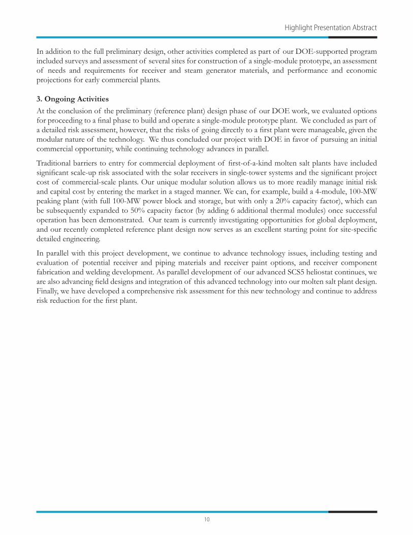
The DOE effort initially focused on a new spaceframe structure, referred to as the Phoenix. The Phoenix is an all-aluminum spaceframe design with a pinned hub structure that allows rapid assembly and low cost extruded structural members. The design offered improved torsional strength compared to torque box designs like the EuroTrough. The goal of the Phoenix was to achieve the optical tolerances required without the need of a precision assembly jig. Jig alignment is a major contributor to the labor needed for collector assembly. The Phoenix design also has substantially fewer parts and fasteners than the ASTR0. Abengoa demonstrated the aluminum Phoenix collector design at Xcel’s Cameo coal hybrid demonstration project near Grand Junction, Colorado during 2010 (see photo below). The Phoenix collectors used at Cameo demonstrated the rapid assembly potential of the collectors, but did not achieve the desired optical performance. A jig aligned steel version of the Phoenix was subsequently developed. The new Steel Phoenix represents a 10% reduction in cost from Abengoa’s ASTR0 collector technology. The Steel Phoenix is Abengoa’s current commercial collector design.
Under the DOE project, Abengoa continued to develop more advanced parabolic trough collector technology. The goal was to achieve an additional 20% reduction in solar field cost while allowing collectors to operate at temperatures up to 550 C. Abengoa has developed its new SpaceTube design which has a structurally efficient and torsionally rigid central truss structure with an optically accurate platform to support mirrors. The new
14
Highlight Presentation Abstract
design has an aperture of over 8 meters and is design to operate with direct steam generation, or molten salt at temperatures up to 550C. The SpaceTube collector will be thermally tested later this year.
3. Solana Solar Power Plant
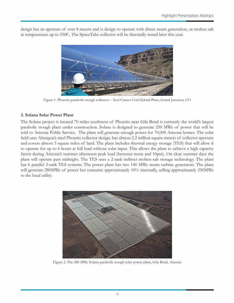
The Solana project is located 70 miles southwest of Phoenix near Gila Bend is currently the world’s largest parabolic trough plant under construction. Solana is designed to generate 250 MWe of power that will be sold to Arizona Public Service. The plant will generate enough power for 70,000 Arizona homes. The solar field uses Abengoa’s steel Phoenix collector design, has almost 2.2 million square meters of collector aperture and covers almost 3 square miles of land. The plant includes thermal energy storage (TES) that will allow it to operate for up to 6 hours at full load without solar input. This allows the plant to achieve a high capacity factor during Arizona’s summer afternoon peak load (between noon and 10pm). On clear summer days the plant will operate past midnight. The TES uses a 2-tank indirect molten-salt storage technology. The plant has 6 parallel 2-tank TES systems. The power plant has two 140 MWe steam turbine generators. The plant will generate 280MWe of power but consume approximately 10% internally, selling approximately 250MWe to the local utility.
Figure 1. Phoenix parabolic trough collector – Xcel Cameo Coal Hybrid Plant, Grand Junction, CO
Figure 2. The 280 MWe Solana parabolic trough solar power plant, Gila Bend, Arizona

15
SunShot Concentrating Solar Power Program Review 2013
High-Efficiency Low-Cost Solar Receiver for Use in a Supercritical-CO2 Recompression Cycle
S. Sullivan1, E. Vollnogle2, J. Kesseli3, and J. Nash4
1Brayton Energy, LLC, 75B Lafayette Road, Hampton, NH 03842, [email protected] 2Brayton Energy, LLC, [email protected]
3Brayton Energy, LLC, [email protected] Energy, LLC, [email protected]
1. Background
High performance supercritical carbon dioxide (s-CO2) Brayton-cycle engines are currently under development and promise to significantly reduce LCOE via high cycle efficiency. The proposed receiver uses s-CO2 as the heat transfer fluid, enabling these highly efficient engines to be used in concentrated solar power (CSP) applications. A solar receiver adapted to the s-CO2 recompression cycle, with extended heat transfer surfaces, a low-cost quartz window assembly, and the low-cost materials and straightforward manufacturing methods which these elements allow, represents a major advancement in technology over the state-of-the-art in CSP systems, and will contribute directly to the SunShot goal of 6¢/kW-hr.
2. Objectives
The fundamental goal of the proposed project is to design and demonstrate a low-cost, high efficiency solar receiver that is compatible with s-CO2 cycles for use in utility scale and distributed electrical power generation. The primary objectives of this solar receiver development include:
• Receiver working fluid (CO2) outlet temperature ≥ 750°C• Annual average receiver thermal efficiency ≥ 92% • Receiver fatigue life ≥ 10,000 thermal cycles w/o failure• Receiver creep life ≥ 90,000 hours (30-year operational life)• Cost of receiver subsystem ≤ $30/kWthermal • Receiver pressure drop ≤ 5% dP/P
To satisfy these program objectives, a combination of analytical modeling and hardware testing will be performed, and results reported.
3. Key Findings
Since the activation of the award in September 2012, work has been accomplished in each of the key development areas:
• Completion of Extended Surface Tube (EST) numerical finite-difference thermal model using non-linear s-CO2 properties (Figure 1)
• Development of manufacturing techniques critical to the implementation of wire-mesh extended heat transfer surfaces in a receiver system
• Preliminary testing of candidate wire-mesh architectures suitable for application as heat transfer enhancing surfaces in a solar receiver system
• Development of costing method, and preliminary costing of absorber elements

16
• Absorber element creep, fatigue, and corrosion testing development • Development and fabrication of two test rigs:
- High-flux rig for evaluating the thermo-mechanical stresses induced by high incident fluxes and the fatigue induced by thermal cycling (Figure 2)
- High-temperature furnace rig for evaluating the corrosion of candidate alloys in an s-CO2 environment, and the pressurized creep life of candidate structures under anticipated cycle conditions (Figure 3)
• Identification of alternative novel solar absorber cavity shapes, form factors, and heat transfer augmentation strategies (internal cavity vs. external receiver, plate fin, plate-mesh, flattened tube, localized use of static flow mixers, etc.)
• Ongoing communication with s-CO2 engine developers to - anticipate scaling requirements, - address key barriers to successful implementation, and - work towards ultimately producing a solar receiver compatible with a s-CO2 power cycle for full
system demonstration.
Figure 1. Representative finite difference elements in EST model
Figure 2. High Radiant Flux Rig
Figure 3. High Temperature Furnace
Thermal Receivers: Supercritical Carbon Dioxide and Molten Salt

17
SunShot Concentrating Solar Power Program Review 2013
Direct s-CO2 Receiver DevelopmentM. Wagner1, Z. Ma2, J. Martinek3, T. Neises4, and C. Turchi5
National Renewable Energy Laboratory, Golden, CO, [email protected], [email protected], [email protected], [email protected], [email protected]
1. Introduction
This project undertakes the task of developing a high-temperature receiver technology using that directly heats supercritical carbon dioxide (s-CO2) in the receiver and delivers it to the power cycle without intermediate heat exchange. An emerging power cycle technology that uses s-CO2 as the working fluid shows promise for exceeding 50% conversion efficiencies in a dry-cooled configuration at turbine inlet temperatures above 650°C. Compared to conventional steam plants, the prospective efficiency boost promises significant plant cost reductions for CSP technologies, though no current receiver technology can operate under the required conditions. Two classes of high-temperature, high-pressure receiver are explored in this work with the most promising technology planned for small-scale prototype demonstration. Initial work has focused on development of a novel configuration of a more conventional tubular-receiver design. Future work will continue to develop the tubular concept and investigate the viability of directly irradiated micro-channel compact heat exchangers, which are capable of high temperature/pressure operation.
2. Objectives
The project will to develop, characterize, and experimentally demonstrate the novel high-temperature s-CO2 receiver technology. To be considered successful the commercial technology must achieve the SunShot receiver targets of greater than 90% thermal efficiency while heating the fluid to 650°C. The commercial receiver will also be able to withstand 10,000 thermal cycles before mean-time-to-failure and have an expected commercial cost of less than 150 $/kWt. A prototype receiver system will be constructed and tested with a goal of demonstrating key technology capabilities and validating the performance model that will be used to develop the commercial receiver design. Outcomes from this project include the characterization of multiple novel direct receiver concepts through detailed performance modeling, the development of intellectual property from the designs, and the dissemination of design results to technology developers. This project will also produce a set of modeling tools and methodologies that can be used by other parties to deploy the direct receiver technologies for s-CO2 systems.
3. Key Findings
Power tower receiver design must be closely coupled with the solar field optical capabilities and the operation of the power cycle system, including thermal storage. An effective flux distribution maximizes delivered power while delivering an even energy profile that can be absorbed by the thermal receiver efficiently and within material strain limitations to maximize component lifetime. Receiver geometry definition must account for the capabilities of the solar field from the outset to ensure viable specifications and realistic thermal efficiency calculations. For example, an aiming strategy that assumes all heliostats reflect towards the centroid of the aperture will do not capture the limitations on receiver size and inherent optical loss associated with realistic aiming algorithms. Work under this project has augmented existing tools such as SolarPILOT and SolTrace [1] to model the interaction between the heliostat field and the receiver. Figure 1 shows the difference between a “centroid” aiming approach and the more realistic aiming strategy used for this project.

18
Thermal Receivers: Supercritical Carbon Dioxide and Molten Salt
Likewise, the receiver design depends strongly on the operation envelope of the power cycle and thermal storage system. NREL has worked with the University of Wisconsin to develop detailed power cycle and sub-component performance models that can be used to define receiver operating conditions [2].
Because this project investigates receiver geometries that have not been demonstrated experimentally – seeking high-temperature operation with high thermal efficiency – an important part of the receiver design process is thermal loss characterization using computational fluid dynamics software. Thermal losses that detract from the overall receiver efficiency include lost reflection of incident irradiation, re-emission of radiative energy from heated absorber surfaces, and convective/advective loss from the heated receiver surfaces. The thermal losses are coupled with the receiver surface temperatures, so NREL is optimizing the direct s-CO2 receiver design by integrating flux, radiation, and convection models. This capability has enabled sensitivity analysis that more thoroughly explores design options, including the effect of receiver orientation, shown in Figure 2.
4. References
[1] T. Wendelin, “SolTRACE: A New Optical Modeling Tool for Concentrating Solar Optics,” in ASME 2003 International Solar Energy Conference, 2003.
[2] C. S. Turchi, Z. Ma, T. Neises, and M. J. Wagner, “Thermodynamic Study of Advanced Supercritical Carbon Dioxide Power Cycles for High Performance Concentrating Solar Power Systems,” in Proceedings of the 2012 6th International Conference on Energy Sustainability, 2012.
Figure 2. Sensitivity of natural convection losses in a cavity receiver to aperture elevation angle.
Figure 1. Receiver flux profile aiming strategies used in the receiver design process - realistic flux profile (left) and simplistic approach (right).

19
SunShot Concentrating Solar Power Program Review 2013
High Flux Microchannel Receiver Development with Adaptive Flow ControlM. Drost1, R. Wegeng2, S. Apte3, and V. Narayanan4
1Oregon State University, Corvallis, OR 97330, [email protected] Northwest National Laboratory, [email protected]
[email protected]@oregonstate.edu
1. Background
In any diffusion limited process, such as heat transfer, the residence time required for a fluid to come into equilibrium with the walls of a channel decreases as the square of the diffusion lengthens. Generally the size of a heat transfer device is directly related to the residence time of the fluid being heated, and hence, the size and cost of a device will decrease as the square of the diffusion length. This insight has led to the use of microchannels in a range of high flux heat transfer applications. This project takes advantage of the extremely high heat transfer rates afforded by microchannels, demonstrate a microchannel-based solar receiver capable of absorbing high solar flux while using a variety of liquid and gaseous working fluids. The development of a high flux microchannel receiver has the potential to dramatically reduce the size and cost of a solar receiver while minimizing reradiation and convective losses, thereby increasing the receiver efficiency. The microchannel solar receiver concept can be applied to a wide range of solar technologies ranging from dish concentrators to solar central receivers.
The proposed concept consists of using a modular arrangement of arrayed microchannels to heat a working fluid in a concentrating solar receiver, allowing a much higher solar flux on the receiver and consequently a significant reduction in size, cost and thermal losses. As an aid in visualization of this concept, a potential configuration for a central receiver is provided Figure 1. An array of receiver panels is located on the back face of a cavity to form the central receiver. The design is inherently modular, and a large central receiver would be assembled from a number of receiver panels given a desired receiver output. Our work will focus on flat plate microchannel receiver panels such as that shown in Fig.1, which is applicable to central receiver applications.
An individual panel will be fabricated by using chemical etching to form flow features into thin laminae of substrate material. The laminae will then be stacked and bonded to produce a thin receiver panel that includes the complex set of microchannels. As part of developing microchannel steam reforming reactors, these fabrication techniques have been applied to a wide range of high temperature materials including stainless steel and refractory metals.
To further enhance microchannel receiver performance, we will investigate incorporating adaptive flow control features that use differences in thermal expansion to increase the flow to hotter sections of the receiver,
Figure 1. Microchannel solar receiver concept.

20
Thermal Receivers: Supercritical Carbon Dioxide and Molten Salt
minimizing hot spots and providing more uniform heating of the working fluid. These adaptive flow features will be designed to adjust the flow within an appropriate range based on working fluid properties and solar fluxes expected at the receiver’s surface.
2. Objectives
We plan to develop two microchannel solar receiver designs, one for liquid cooled microchannel receivers and one for gas cooling. Metrics for the supercritical-CO2 receiver will be based on “on sun” experimental results. Metrics for the other design will be based on laboratory test results and modeling and simulation.
• Liquid Working Fluid Microchannel Receiver Metrics - Our performance metrics are to: 1) Use simulation to demonstrate our ability to design a molten salt cooled microchannel receiver operating at a fluid exit temperature of 600 ºC capable absorbing an average flux of 400 W/cm2; and 2) In laboratory testing, this receiver will be experimentally demonstrated for a heat flux of 400 W/cm2 but the exit temperature of the solar salt will be limited to 550 oC due to the temperature limits of existing salts.
• Gas Working Fluid Microchannel Receiver Metrics - Our metric for gaseous coolants is to use simulation and analysis to demonstrate our ability to design a supercritical-CO2 receiver operating with a receiver exit temperature of ≥650 ºC and capable of absorbing an average flux of 100 W/cm2. We will keep pressure drop below 0.35bar. The surface temperature of the receiver will be consistent with a receiver thermal efficiency of 90%. Using supercritical-CO2 as the working fluid, this receiver design will be experimentally demonstrated in laboratory testing and also demonstrated on the PNNL solar dish.
3. Key Findings
During the first seven months of the two year project we have been primarily focused on designing and assembling test articles and test apparatus. Key accomplishments and finding include:
• Computational Fluid Dynamics (CFD) results confirm that we will be able to attain our performance objectives for the supercritical-CO2. We will simulate the molten salt receiver later in the project along with receivers designed for higher CO2 operating pressures.
• For the supercritical-CO2 receiver we have selected Haynes 214 as the fabrication material for our test article. This is due to Haynes 214 high temperature performance and vendor experience in etching and bonding.
• The internal structure of the supercritical-CO2 receiver test article has been optimized and we have selected an array of microscale pins for our heat transfer surface. We have optimized the design to insure that we have good thermal performance while maintaining sufficient bonding area to contain the very high pressure we will encounter in the CO2 receiver. The design has been reviewed and provided to the fabrication vendor.
• We have completed the design and procurement of the flux concentrator and we are currently assembling the device which will be capable of producing a flux of 400 W/cm2 on a test article with dimensions of 2 cm on a side.
• We have completed the design and we are now assembling test loops for both supercritical-CO2 and molten salt. We have also completed the assembly of a test apparatus to allow pressure testing at testing of test articles at 100 bar and 650 C.

21
SunShot Concentrating Solar Power Program Review 2013
Advanced Low-Cost Receivers for Parabolic TroughsJ. Stettenheim1, T. McBride1, O. Brambles1,
P. Magari2, B. Davis2, M. Iveson2, W. Chen2, R. Kaszeta2, N. Kattamis2, and C. Cheng3
1Norwich Technologies, 52 Bridge Street, White River Junction, VT 05001, [email protected] Inc.
3ANSYS Consulting Group
1. Background
In presently available receivers, a central liquid-carrying tube with an outer optical absorption coating is surrounded by a vacuum within a transparent concentric jacket. Numerous challenges exist with such state-of-the-art vacuum receivers: their absorption coatings are expensive and technologically intensive, vacuum degradation causes failure of 1–5% of tubes per year, the thick glass envelope is expensive, and prohibitive T4 radiation losses prevent practical operation at elevated temperatures (>500 ºC). [1,2,3] Our novel receivers will address all of these major challenges. Our receivers have the potential to (1) dramatically reduce radiation losses at higher temperatures, (2) significantly increase reliability by eliminating the vacuum, (3) decrease acquisition costs due to simpler structure and manufacture, and (4) operate at higher T with high efficiency. By exceeding the SunShot Vision Study parabolic trough receiver targets, our novel system provides a viable pathway to SunShot’s 6¢/kWh goal. [4]
2. Objectives
This project is directed at developing a novel receiver for parabolic-trough concentrating solar power (CSP) systems that will dramatically improve performance while substantially reducing acquisition and operation and maintenance costs. The objectives of this project are (1) to design an advanced receiver (heat collecting element, HCE) for concentrating solar power that incorporates novel materials and design features to achieve lower cost, higher efficiency, and higher reliability, and (2) to build and test the performance of a manufacturable, working prototype of the advanced cavity receiver. This project will deliver a novel receiver for trough applications designed and modeled to operate at ≥90% thermal efficiency with an exit heat transfer fluid temperature ≥650°C at a cost of ≤$150/kWth.
This twelve month project includes extensive design modeling work, followed by the construction and testing of a prototype advanced receiver for trough-based CSP; the developed receiver will achieve lower cost, higher efficiency, and higher reliability than current receivers.
Our technical approach includes working with modeling experts in both the optical and thermal domain – Creare, Inc. for Zemax optical modeling and ANSYS Consulting Group for ANSYS Fluent CFD thermodynamics simulation tools – to develop top level modeling capabilities. In particular our approach includes rigorous modeling of the state-of-the-art existing receiver technology, validation of those models with literature data, and parameter analyses based on selected modifications to the state-of-the-art. This extensive modeling, combined with materials research including development of a large matrix of material options and characteristics, has been used to refine and exhaustively characterize our novel receiver designs. Based on this development of an optimized design, we are building and will test a prototype receiver. All test procedures are based on established NREL testing methods.
3. Key Findings
Current results for the NT design show that through the co-optimization of thermal and optical efficiencies, even with operation in air and the complete removal of receiver vacuum, thermal performance at current operating temperatures is moderately better than current state-of-the-art (SOA) receivers and performance at

22
high temperatures is substantially superior to the SOA receiver. (Fig. 1). Economically in terms of acquisition and maintenance and operation costs, the NT design is superior over SOA because it removes the need to generate and maintain vacuum.
The NT design is optimized for maximizing solar field efficiency and is thus a compromise between optical
and thermal performance. The NT design allows for major thermal gains over SOA receivers at operating temperatures above 400ºC, while maintaining near equivalent optical efficiency. When considering the entire solar field (which operates over a range of temperature between an inlet and outlet fluid temperature), the NT design substantially outperforms the SOA receiver at all times of the day when operating at temperatures exceeding 250ºC. As shown in Fig. 2, the solar field efficiency of the NT receiver substantially exceeds the SOA receiver for a plant operating with an inlet fluid temperature of 350ºC and outlet fluid temperature of 650ºC.
4. References
[1] Burkholder F, Kutscher C. “Heat Loss Testing of Schott’s 2008 PTR70 Parabolic Trough Receiver” (NREL/TP-550-45633): NREL, 2009.
[2] Kutscher C, et al. “Line-Focus Solar Power Plant Cost Reduction Plan: NREL Milestone Report”, 2010.
[3] Mahoney R. “Trough Technology—Heat Collector Element (HCE) Solar Selective Absorbers” (Trough Workshop, ASES 2000): Sandia National Laboratories, 2000.
[4] SunShot Vision Study, US Department of Energy, 2012.
Thermal Receivers: Supercritical Carbon Dioxide and Molten Salt
Figure 1. Thermal efficiency of the NT receiver compared with SOA current receivers at different operating temperatures.
Figure 2. Simulated Solar field efficiency (product of thermal and optical efficiency over a range of insolation during a typical operating day) of current SOA receivers (PTR70) and Norwich Technologies (NT) design #1 and design #2 for a solar field fluid
exit temperature of 650°C (inlet fluid temperature of 350°C).

23
SunShot Concentrating Solar Power Program Review 2013
Sulfur Based Thermochemical Energy Storage for Solar Power TowerB. Wong1, L. Brown1, R. Buckingham1, D. Thomey2, M. Roeb2 and C. Sattler2
1General Atomics, 3483 Dunhill St., San Diego, CA 92121, [email protected] Institute of Solar Research, Linder Hoehe, 51147 Cologne, Germany
1. Introduction
The feasibility of a sulfur based thermochemical cycle (TC) to store high temperature solar heat from a concentrated solar power (CSP) tower was validated in Phase I. The TC consists of three reaction steps: (1) Concentrated sulfuric acid is decomposed on sun into water, sulfur dioxide and oxygen. The decomposed oxygen is separated and discharged; (2) Sulfur dioxide then reacts with water and undergoes disproportionation to reform sulfuric acid and elemental sulfur. The sulfuric acid produced is concentrated and returned to step one for decomposition. In essence, solar heat is converted into elemental sulfur in this thermochemical energy storage (TES) scheme. (3) The sulfur generated is directed to storage at the desired rate, and/or to a sulfur burner and combusted in the presence of air to produce heat for electricity production. This sulfur dioxide generated is returned to the disproportionation reactor. Engineering development of a CSP plant integrated with sulfur storage is currently on going in Phase II. Since sulfur combustion is a commercial process, this project focuses on developing the first two reaction steps to prepare the process for on sun engineering demonstration.
2.1. H2SO4 Decomposition
On sun testing of a two chamber solar receiver-reactor for sulfuric acid decomposition was carried out in Phase I [1]. Measurement results showed decomposition takes place down to 650°C (Figure 1) and the thermal efficiency of the receiver for SO3 decomposition was calculated to be approximately 50% at a SO3 conversion of 50%. The results were used to evaluate the decomposer and catalyst characteristics in addition to establishing a scale up concept design applicable to a CSP tower in Phase II. Suitable catalysts for operation between 600 and 850°C have been identified and are being tested. Fe-Cr based oxides are undergoing testing to gauge their long term performance (up to 1000 hours) in the laboratory (Figure 2). Vanadium based oxide and platinum catalysts will be tested for operation at 650°C and below [2]. Even though a lower decomposition temperature increases the amount of acid recycle, the solar installation cost is reduced significantly which will lead to a corresponding lower levelized cost of electricity (LCOE). Based on catalyst stability and conversion rate data, final decomposer and solar plant designs will be established.
2.2. SO2 Disproportionation
In Phase I, homogeneous iodide catalysts were shown to greatly improve the disproportionation kinetics with a disproportionation rate of 2.5%/hours. The team is continuing investigations on the effect of various process conditions such as catalyst quantity, temperature and pressure on disproportionation in Phase II. The incorporation of catalyst was found to not only enhance reaction kinetics but also extend the degree of disproportionation (Figure 3). Sulfuric acid concentration of up to 58 wt%, as opposed to around 40 wt%, was obtained in the presence of catalyst. Furthermore, we were able to increase the disproportionation rate to 20%/hr (Figure 4) by increasing the operating temperature and catalyst quantity. However, the use of catalyst requires its extraction from the resulting sulfur and sulfuric acid. Both of these processes have been successfully demonstrated. Hence, the team was able to define a complete SO2 disproportionation process cycle using laboratory results. Finally, a catalyst modified disproportionation path is proposed.

24
3. CSP Plant Efficiency and Economics
A 50MWe CSP plant flowsheet integrated with sulfur storage was established based on design and experimental data. Costs of conceptual process equipment were computed and the results were incorporated into System Advisor Model (SAM) to estimate the solar power tower system cost. The overall efficiency of converting solar heat → elemental sulfur → combustion heat → electricity was calculated to be around 26.7%. The storage cost for sulfur is very low at $1.37kW/kwht and a LCOE of $0.081/kwhe was derived based on 2009 cost data.
4. References
[1] D. Thomey, L. de Oliveira, J.-P. Säck, M. Roeb, C. Sattler (2012). International Journal of Hydrogen Energy Volume 37, Issue 21, November 2012, Pages 16615–16622.
[2] M. Machida, N.Hayashida, T.Kawada, S.Hebishima, K.Ikeue and S.Takeshima, 25th Japan-China Environmental Catalyst Work Shop at Shanghai (2011).
Thermal Storage and Heat Transfer Fluids: Thermochemical
Figure 1. SO3 conversion as a function of temperature and acid flow rate.
Figure 3. Effect of catalyst and temperature on SO2 disproportionation rate and final H2SO4 concentration.
Figure 2. Long term sulfuric acid decomposition catalysts test set up
Figure 4. Effect of iodine fraction on SO2 disproportionation rate.

25
SunShot Concentrating Solar Power Program Review 2013
Chemically Reactive Working Fluids for the Capture and Transport of Concentrated Solar Thermal Energy for Power GenerationR. Brotzman1, M. Urgun-Demirtas2, and J. Libera2
1Argonne National Laboratory, 9700 S. Cass Ave. Bldg. 362, Argonne, IL 60439, [email protected] National Laboratory, [email protected] and [email protected]
1. Introduction
This program objective is to demonstrate the feasibility of employing chemically reacting fluids (CRWFs) as heat transfer fluids for advanced CSP systems at lab-scale. CRWFs capture solar heat as chemical energy in addition to sensible heat and latent heat – enabling substantially more heat/mass to be captured and operating temperatures in the range of 650°C–1200°C. Power system computations indicate CRWFs have the potential to more than double the power output of CSP systems. This is a 2-year feasibility program.
2. Background
This work addresses the cost barrier of power produced by CSP plants. Specifically, this research addresses the primary heat transfer fluid (HTF), which transmits the collected solar power to the power cycle. Current state-of-the-art CSP has a maximum solar-to-electric efficiency of 29.4%. [1] Operational, industrial-scale plants have an efficiency of less than 15% because primary HTFs absorbs solar heat as sensible heat at near atmospheric pressure in the solar collector and are pumped through heat exchangers to transfer heat to water to produce steam for power generation. Current HTFs are limited:
• Heat is transmitted as sensible heat. The heat capacity of current HTFs is ~1/2 of water (1.5 - 2.5 vs. 4.18 kJ/kgK) necessitating larger flow-rates to transmit equivalent amounts of heat. Larger flow-rates require larger pumping equipment, more heat transfer surface area, and higher process costs.
• Current HTFs are generally limited to less than 400°C because the fluids are chemically unstable at higher temperatures and cannot then be easily regenerated. While inorganic salts can be used up to 600°C, they become solids below ~230°C and cannot be pumped; these systems are expensive and require additional process controls to maintain flow.
• The superheated steam generated by existing HTF is generally limited to ~360°C and 70 bars pressure. Because its saturation temperature is 165°C, most of the heat is available at temperatures less than 165°C.
Therefore, improvements in HTFs are required to fully realize CSP solar collection potential.
3. Objectives
• The feasibility of employing chemically reacting fluids (CRWFs) as a HTF for CSP systems will be demonstrated. Success metrics will be generated for CRWFs in order to provide a ranked-order list of each CRFW’s potential ability to capture solar heat as chemical energy in addition to sensible heat and latent heat. The efficiency and longevity of candidate systems will be demonstrated by repeated cycling in the temperature ranges of 650°C–1200°C.
• Thermodynamic and process simulations will be conducted using Aspen Plus®, and combined with published kinetic data to identify CRWF candidates and process windows that enable reversible reactions, which efficiently recover CSP heat for power generation at temperatures in the range of 650°C-1200°C.
• CRWF cycling experiments will be designed to demonstrate thermal capture, transport, and release between 650°C and 1200°C, below 160-bar. Experimental data will be compared with commercial HTF’s DOWTHERM A® and Solar Salt. The experimental data will also be compared to systems that use air

26
as the working fluid and to the models of super critical CO2 as a working fluid. The compatibility with CSP system components, material availability, cost competitiveness, safety, environmental impact, and the need for catalysts will be evaluated.
4. Key Findings
Thermodynamic and process simulations are summarized in Table 1. CRWF kW turbine power generated per kmole CRWF flow at 1000°C and 50 bar are compared with power generated for water under similar process conditions. The candidate CRWFs produce 20% to 100% more power, with the exception of NH3.
Table 1. Thermodynamic and process simulations on candidate CRWF
CRWF Candidate kW turbine power/kmole CRWF/hr flow @ 1000C - 50 bar
Normalized to Water’s Power
0.95 C2H6 and 0.05 H2 18.15 2.03SO3 16.12 1.810.5 CH4 and 0.5 CO2 12.67 1.420.33 CH4 and 0.67 H2O 10.71 1.20NH3 5.59 0.63H2O 8.92 1.00
Processes simulations of the CRWF candidates indicate regeneration equilibrium governs heat and exergy gain, and power generated from each CRWF. Catalysts only effect reaction-transition states, or enable the selection of reaction products by stabilizing specific transition states – catalysts do not shift equilibrium. Thus for the CRWFs evaluated the only effect a catalyst would have on the process is the rate at which equilibrium is achieved, or put another way, enabling equilibrium to be achieved at shorter residence time – more energy could be generated in a given system by pumping the CRWF through the system faster.
5. References
[1] Washom, B., 1984, Paper No. 849516, Proceeding of the IECEC, San Francisco, CA.
Thermal Storage and Heat Transfer Fluids: Thermochemical

27
SunShot Concentrating Solar Power Program Review 2013
Low-Cost Metal Hydride Thermal Energy Storage System for Concentrating Solar Power Systems
R. Zidan1, T. Motyka1, B. Hardy1, J. Teprovich1, D. Knight1, B. Peters1, C. Corgnale2, and C. Buckley3
1Savannah River National Laboratory, 999-2W, Aiken, SC 29808, [email protected], [email protected] The Center for Hydrogen Research, [email protected]
3 Curtin University, [email protected]
1. Background
Three of the major improvement areas for Thermal Energy Storage (TES) system are in 1) lowering their costs, 2) reducing their full charging time to less than 6 hours and 3) increasing their temperature of operation to improve the CSP overall production efficiency. Metal hydride (MH) TES systems have the ability to enable all of these improvements. In addition, many of the high and even the new lower temperature metal hydrides are fairly inexpensive. Preliminary calculations indicate that existing metal hydride TES systems can approach $15-$25/kWh. Because of their very high thermal capacity, the size of the overall TES system along with its associated BOP can be substantially reduced leading to additional capital cost savings. MH TES systems can also be made to be self-regulating, thereby simplifying their design and lowering not only their capital but their operating costs as well [1].
2. Objectives
The objectives of this research are to evaluate and demonstrate a metal hydride-based TES system for use with a CSP system. Because of their high energy capacity and reasonable kinetics many MH systems can be charged rapidly. Metal hydrides for vehicle applications have demonstrated charging rates in minutes and tens of minutes as opposed to hours. This coupled with high heats of reaction allows MH TES systems to produce very high thermal power rates (approx. 1kW per 6-8 kg of material) [1]. A major objective of this work will be to evaluate some of the new metal hydride materials that have recently become available.
A unique approach is being applied to this project that makes use of a hierarchical modeling methodology developed by the Savannah River National Laboratory (SRNL) [2]. This approach combines our modeling experience with the extensive material knowledge and expertise at both SRNL and Curtin University (CU) to screen several promising metal hydride candidate materials and then select the best candidates for more thorough evaluation through experiments and more detailed models. During the second year, material optimization, bench-scale testing and more detailed component and system models will lead to a proof-of-concept demonstration and a preliminary system design. The culmination of this proposed research will be the design, fabrication and evaluation of a prototype MH energy storage system that is aimed at meeting the SunShot cost and performance targets for TES systems.
3. Key Findings
3.1. Obtain and Generate Preliminary Material Engineering Data
SRNL and CU have collected and evaluated material property data for over 20 MH candidates. Preliminary data obtained include: enthalpy of reaction, weight and volume fraction capacities, density, equilibrium temperatures/pressures and specific cost. These material properties were used for preliminary screening of materials to arrive at those materials with the highest potential to meet TES SunShot targets. More specific material properties such as reaction rate and cycling performance are being obtained through our experimental program.

28
3.2. Refine and Apply Material Screening Tool (Preliminary System Models)
A tool has been set up with the aim of screening, comparing and verifying the behavior of MH pairs with the potential of achieving the SunShot TES targets. System cost and maximum operating temperature (which are among the most challenging targets) have been evaluated and compared against the targets. The installed cost of the system has been assessed adopting a factored method approach [3], accounting for the cost of the MH material and of the heat exchanger. The cost of the material has been assessed based on raw cost of
the MH material with additional costs included to account for preparing, handling and accommodating the material inside the tank. A shell and tube heat exchanger concept has been assumed as the baseline heat transfer system and its installed cost (i.e. tubes and vessel cost) has been assessed based on the heat transfer area, operating conditions, materials and component installation costs. Installed cost of selected high temperature systems are reported in Figure 1, showing the specific cost ($/kWhth), with the contribution of the material and the heat exchanger shown. Mg-family materials, as well as CaH2 and NaH, show a specific cost lower than the SunShot target (15 $/kWhth) and, consequently, were chosen as the baseline materials for the high temperature (HT) side of the
system. Based on these and other results, 12 MH pairs were selected with the potential of meeting SunShot targets. These pairs are reported in Table 1.
Table 1. Material Pair (High Temperature and Low Temperature MH) Candidates for MH TES System
HTMH –LTMH
MgH2 – TiCr1.8H3.5
Mg2FeH6 – TiMn1.5H2.5
CaH2 – NaAlH4
MgH2 – TiMn1.5H2.5
NaMgH3 – TiFeH2
NaH – TiFeH2
HTMH –LTMH
Mg2FeH6 – TiFeH2
NaMgH3 – TiMn1.5H2.5
NaH – TiMn1.5H2.5
Mg2FeH6 – TiCr1.8H3.5
NaMgH3 – NaAlH4
NaH – NaAlH4
3.3. Design and Fabricate a Bench-Scale MH TES System
To further evaluate the best candidate material pairs, SRNL is designing and fabricating a bench-scale MH TES system suitable for testing 10-20 g of material. The purpose of this system is to provide materials engineering data on the performance of the selected MH material pair as well as to obtain longer-term performance data for the development of future TES systems. Currently, the design of the TES system has been completed and approximately 60% of the system has been assembled. The final system assembly will commence following the receipt of the remaining system components in late April. The system is scheduled for completion and startup by the end of September.
4. References
[1] Harries D, M. Paskevicius, D, Sheppard, emt al. “Concentrating Solar Thermal Heat Storage Using Metal Hydrides” Proceedings of the IEEE, 2012, 100, 2, 539-549.
[2] Hardy BJ, DL Anton, “Hierarchical Methodology for Modeling Hydrogen Storage Systems, Part II: Detailed Models, International Journal of Hydrogen Energy, 34, 2992:3004 (2009).
[3] Guthrie KM. “Data and Techniques for Preliminary Capital Cost Estimating”, Chem. Eng. Progr. 1969: 114–42.
Thermal Storage and Heat Transfer Fluids: Thermochemical
Figure 1. HTMH material systems specific cost ($/kWhth)

29
SunShot Concentrating Solar Power Program Review 2013
Reversible Metal Hydride Thermal Energy Storage for High Temperature Power Generation Systems
E. Rönnebro1, G. Whyatt1, M. Powell1, K. Simmons1, Z. Fang2, and R. White3
1Pacific Northwest National Laboratory, Richland, WA 99353, [email protected] of Utah, [email protected]
3Heavystone Lab LLC, [email protected]
1. Background
Thermal energy storage is a key enabling technology for concentrated solar power and other renewable energy applications. There are currently no advanced materials available for high-temperature thermal energy storage. The state of the art is molten salt systems operating at mid-temperature range of 260-560°C and the energy density is only 153kJ/kg. The molten salt based TES are to a smaller extent commercially available, such as used in Abengoa’s CSP towers and with the solar power dish by Infinia Corp. Inc. Very few large demonstration sites exist worldwide, including the thermal power plant ‘Andasol 1’ in Andalucia, Spain, with a 50MW steam turbine for electricity production which has two insulated storage tanks with molten salt mixtures capable of storing 1,000MWh of heat. Recently, DOE funded projects have focused on new salt and oxide based systems among others but the main issues are low energy densities, cost and not being able to show sufficient cycle life.
Metal hydrides (MH) can store up to 3000kJ/kg in a range of ~100-1000°C, depending on choice of material, thus exceeding the gravimetric and volumetric energy density of all commercially available materials. Low-temperature MH systems up to 200°C have been demonstrated using expensive, less available rare-earth metals based on LaNi5 type alloys. Medium temperature systems of 250-500°C and 20-40 bar H2-pressures have recently been demonstrated in Germany and France based on MgH2, but this particular hydride will not likely obtain the high efficiency target when operated above 600°C, and, hydrogen pressures are impractically high. In comparison with 28,000 tons molten salt storage in Spain, only 1,100 tons of Mg would store the same amount of heat. A commercially viable metal hydride needs to operate at >650°C and 1 bar H2-pressure with long cycle life. There are no data available on using hydride materials reversibly above 600°C and by identifying such a hydride a breakthrough technology can be enabled.
The metal hydride based technology stores solar energy or waste heat in a dual bed metal hydride system for heating. This concept is based on a thermal cycle driven by gas-solid chemical reactions accompanied by heats of formation which provides maximum efficiency. The material is a metal or an alloy reversibly absorbing hydrogen to form a metal hydride. Thermal energy is stored in the chemical bond between the metal and the hydrogen. The heat of reaction absorbed in liberating the hydrogen is the same as the heat of reaction obtained when forming the hydride. No hydrogen is consumed so, theoretically, very little heat is lost. By changing composition, the metal hydride can be engineered to operate at specific temperatures and pressures with formation enthalpies of 30-140 kJ/mol H2. When the hydrogen storage material is exposed to heat, hydrogen is released. When absorbing hydrogen, heat is released. The general reactions, where M is the metal and H is hydrogen are: M + H2 → MH2 + heat (out) (exothermic reaction) and MH2 + heat (in) → M + H2 (endothermic reaction).
The approach of the PNNL-lead team that uniquely distinguishes us from other on-going efforts involves identifying a high-temperature low-cost metal hydride that can operate at >650°C and 1 bar H2-pressure based on easily available metals. The ‘complex metal hydrides’ undergoes an atom rearrangement upon reaction and is less practical for this application. Among this class of hydrides are Mg2NiH4, Mg2FeH6 and borohydrides that typically operate at <600°C at very high pressures which is impractical for large scale applications. Moreover, many of the ‘complex metal hydrides’ are known to have slow kinetics and irreversible side reactions that

30
Thermal Storage and Heat Transfer Fluids: Thermochemical
limit cycle life. To increase efficiencies at higher temperatures and to avoid issues with high pressures, the metal hydrides which simply allows for H2 diffusion without atom rearrangement is a better option for CSP applications and therefore our preferred choice. Among these hydrides only a few are known to operate at >650°C, including LiH, NaH, CaH2, TiH2, ZrH2. A breakthrough is obtained if successfully identifying a metal hydride based on a high-temperature alloy that meets all the requirements for TES for CSP and our goal is to evaluate a 3kWh prototype based on our optimized metal hydride.
2. Objective
Within an awarded ARPA-E HEATS seedling program, Pacific Northwest National Laboratory (PNNL) and the University of Utah (Utah) is exploiting high-temperature reversible metal hydride materials and system design to demonstrate proof of concept for novel hydride-based thermal storage that far exceeds the DOE’s performance and cost targets. During this 2-Years seed project, the PNNL-Utah team will transition this technology from TRL=2 to 3 to attract additional government and private sector investment by reducing technology risk in two ways: 1) By demonstrating the desired cycle life in a reversible hydride at >600°C and low pressures, and 2) through design, construction and operation of a 3 kWh prototype with energy storage densities and exergetic efficiencies that meet or exceed ARPA-E targets.
3. Key Findings
During the first year, we explored high-temperature alloys in order to increase reversible hydrogen content, thus increase thermal energy storage capacity, and to decrease operation pressure to 1 bar. We synthesized several alloys and selected the best composition to obtain reversible cycles at 650°C and 1 bar. We successfully showed feasibility for far exceeding ARPA-E targets and made a go-decision to proceed in the second year with scale-up (with Heavystone Lab) and to build a 3 kWh prototype to demonstrate ‘1 night - 1day cycles’ and feasibility to meet the 95% exergetic efficiency target.
The first year involved two tasks and the key results are summarized below.
Materials Development and Characterization of High-Temperature Metal Hydride
• Selected metal hydride with ~10x higher energy density than molten salt• Volumetric energy density ~200kWh/m3 for system, i.e.8x ARPA-E target• Established operation range of ~650°C and ~1 bar H2 pressure with rapid kinetics
• >30 cycles demonstrated: exceeded goal for 1st year
Design and Build 3kWh TES Prototype
• Two design concepts evaluated by COMSOL modeling to optimize thermal conductivity• Decided on a stainless steel cylinder with Cu-foam to contain the metal hydride powder

31
SunShot Concentrating Solar Power Program Review 2013
Integrated Solar Thermochemical Reaction System for the High Efficiency Production of Electricity
R. Wegeng1, D. Brown1, R. Diver2, P. Humble1, J. Mankins3, D. Palo4, B. Paul5, and W. TeGrotenhuis1
1Pacific Northwest National Laboratory, P.O Box 999, Richland, WA 993522Diver Solar LLC
3SolarThermoChemical LLC4Barr Engineering Company
5Oregon State University
1. Background
This project seeks to advance the Technology Readiness Level of a unique, solar reactor system that efficiently converts concentrated solar energy into chemical energy for hybrid solar/fossil power generation. The project continues work that was previously accomplished under an American Recovery and Reinvestment Act of 2009 (ARRA) project that included the proof-of-principle demonstration of a solar reforming reaction system, using concentrated solar energy to reform methane into synthesis gas (syngas), a combination of hydrogen, carbon monoxide and carbon dioxide, containing a Higher Heating Value (HHV) that is at least 20% greater than the HHV of the original methane stream.
The current effort seeks to develop the Integrated Solar Thermochemical Reaction System as the front-end of a modified, natural gas combined-cycle powerplant that operates with a power block efficiency exceeding 50%. Because the power block is already well-developed, with known performance and costs, the expected result of this project is the opportunity to use solar energy in a hybrid solar/fossil configuration, with electricity production at costs that are competitive with fossil power generation.
Figure 1. PNNL Solar Thermochemical Reaction System within Infinia Heat Drive.
Figure 2. On-Sun Testing.

32
Power Cycles and Thermal Receivers: Hybrid and Air Brayton
2. Objectives
The primary goal of this three-year project is to improve the performance of the solar thermochemical reaction system and reduce the costs of manufacturing critical system components so that the levelized cost of electricity (LCOE) of the hybrid powerplant is no more than 6 cents/kilowatt-hour (¢/kWh) by 2020.
The critical components in the system are reactors and heat exchangers which are being designed to operate with high exergetic efficiencies through the incorporation and integration of micro- and meso-channel process technology (MMPT). Because micro- and meso-channels offer low resistance to heat and mass transport, process systems based on their use can, in principle, achieve energy conversion with minimal destruction of exergy.
To accomplish the overall LCOE goal, the individual objectives of this project include 1) increasing the solar thermochemical augment from about 20% to as much as 28%; 2) increasing the solar-to-chemical energy conversion efficiency from 63% to as much as 75%; and 3) establishing and validating low-cost, mass production methods for the fabrication of the micro- and meso-channel components.
3. Key Findings and Expected Results
The key findings from the previous work come from our initial proof-of-principle demonstration that methane steam reforming can be accomplished with high efficiency using heat from a parabolic dish concentrator to provide the endothermic heat of reaction.
The chemical reaction of interest in our demonstration produces syngas from methane and water (steam), through the following reaction:
CH4 + H2O à CO + 3H2 (idealized reaction1)
In these experiments, which utilized a low-fidelity configuration of a mesochannel reactor and microchannel recuperative heat exchangers within an Infinia heat drive, we accomplished a solar-to-chemical energy conversion efficiency, based on the increase in the HHV of the reacting stream and the direct normal solar energy that was incident upon the dish, of 63±4%.
Thermodynamically, our reaction system is a chemical heat engine, the efficiency of which will be a function of the reaction temperature and effective thermal recuperation. We believe that higher solar-to-chemical energy conversion efficiencies, perhaps as high as 75%, can be obtained by operating the reaction at higher temperatures and through the development of a higher-fidelity microchannel heat exchanger network that employs improved thermal integration. If we are successful at developing this system and in advancing mass-production methods for the component micro- and meso-channel reactors and heat exchangers, we will enable cost-competitive solar thermochemical augments for hybrid power systems that operate with concentrated solar energy and natural gas and/or biogas.
1 In actuality, the steam reforming reaction is typically accomplished with an excess of water, leading to the production of some carbon dioxide, some unreacted water, and a small amount of unreacted methane.

33
SunShot Concentrating Solar Power Program Review 2013
Micromix Combustor for High Temperature CSP Air Brayton Cycle SystemsK. Brun1
and S. Coogan2
1Southwest Research Institute, PO Drawer 28510, San Antonio, TX 78228-0510, [email protected] Research Institute, [email protected]
1. Background
The European Commission has funded the Solugas 4.5 MW Concentrated Solar Power tower gas turbine demonstration project. The demonstration plant began testing in May 2012 and represents the state-of-the-art in hybrid turbine technology. It features the next generation Abengoa Solar heliostats, a high temperature air receiver designed by DLR and built by GEA, and a Mercury 50 gas turbine generator set supplied by Solar Turbines Incorporated and Turbomach. The air receiver operates at temperatures up to 800°C, while the gas turbine combustor inlet temperature is limited to 650°C. In order to meet the DOE SunShot objectives, this demo plant will need to operate at a receiver temperature of 1,000°C.
No combustor technology currently available is compatible with this temperature. The most similar technology program is the ongoing development of micromix injectors for hydrogen combustion. Most recently, European researchers have demonstrated 10 ppm NOx hydrogen combustion at the 200 kW scale using a micromix jet-in-cross-flow injector with 1,600 injection points [1]. Hydrogen exhibits short autoignition delay times and high flame speeds at standard combustor inlet temperatures; therefore, the hydrogen application shares some of the technical challenges of this project. However, combustion with air over a high temperature range requires additional solutions not provided by hydrogen combustion technology. One particular challenge uniquely addressed by this project is the efficient management of airflow, fuel input, and liner cooling needs that vary with inlet air temperature fluctuations.
2. Objectives
The objective of the project is to increase the CSP tower air receiver and gas turbine temperature capabilities to 1,000ºC by the development of a novel gas turbine combustor, which can eventually be integrated on a Mercury 50 gas turbine. This megawatt (MW)-scaled combustion system advances the state-of-the-art from a current technology readiness level (TRL) 3 (initial small scale laboratory size testing) to a full TRL6 (MW-scale prototype demonstration).
A three-phase approach has been implemented to achieve project objectives. During Phase I, the combustor, all of its components (injector, liner, and fuel management system), and a supporting combustion test facility will be fully designed. In Phase II, the test facility and all test articles will be fabricated. Phase III will be dedicated to combustor performance and endurance testing.
3. Key Findings
Modern natural gas combustion systems achieve low emissions by operating in the lean premixed regime where fuel and air are nearly homogenously mixed before entering the combustion chamber. The characteristic time scale for this mixing is much less than the autoignition delay time at normal combustor inlet temperatures. However, autoignition delay time drastically decreases at high temperatures and the delay time for natural gas at 1,000°C is as little as 0.4 ms. This is orders of magnitude less than in current systems and precludes the use of conventional premixed injector technology. The flame speed also experiences a significant increase, making flashback a potential concern. A high temperature CSP combustor design must mitigate the elevated risks of autoignition and flashback so that low emission lean premixed combustion may safely take place.

34
Additional challenges are created by the variability of the high temperature heat source. epending on solar conditions, the combustor inlet air temperature could be anywhere between 600°C and 1,000°C. Because the allowable turbine inlet temperature is fixed, the changing inlet conditions shift the amount of air required for combustion. Approximately 70% of the air is needed for combustion at 600°C, but only 40% is needed at 1,000°C. Because the inlet temperature is also the temperature of the liner cooling gas, the amount of cooling air required to maintain the liner at a target temperature increases with temperature. Therefore, a successful system must have the capability to actively redirect air from the primary zone to cooling channels depending on inlet conditions.
A multi-bank micromix jet-in-cross-flow injector is being designed to solve these challenges and is shown in Figure 1.
Simple but efficient jet-in-crossflow mixers are used in many small passages to reduce length scale and achieve premixing before autoignition. Passages are distributed in a novel multiple bank arrangement with independent fuel controls. When the combustor inlet temperature is high, fuel is delivered only to the innermost bank. Air flowing through the outermost banks does not receive fuel and instead serves as liner film cooling. This cooling air is not expected to unduly influence combustion because of the short flame length scale established by the micromix design. Additional fuel banks are activated for lower temperature operation, incrementally shifting the airflow distribution between combustion and cooling without any moving parts.
In summary, a micromix combustor design is being pursued that achieves low emissions despite autoignition and flashback hazards, efficiently redistributes air based on changing solar conditions, and uses adaptive cooling to maintain liner temperatures within metallic material limits.
4. References
[1] Boerner, S., et al., 2013 “Development and Integration of a Scalable Low NOx Combustion Chamber for a Hydrogen-fueled Aerogas Turbine,” Progress in Propulsion Physics, 4, pp. 357-372.
Power Cycles and Thermal Receivers: Hybrid and Air Brayton
Figure 1. Multi-bank micromix jet-in-cross-flow injector design
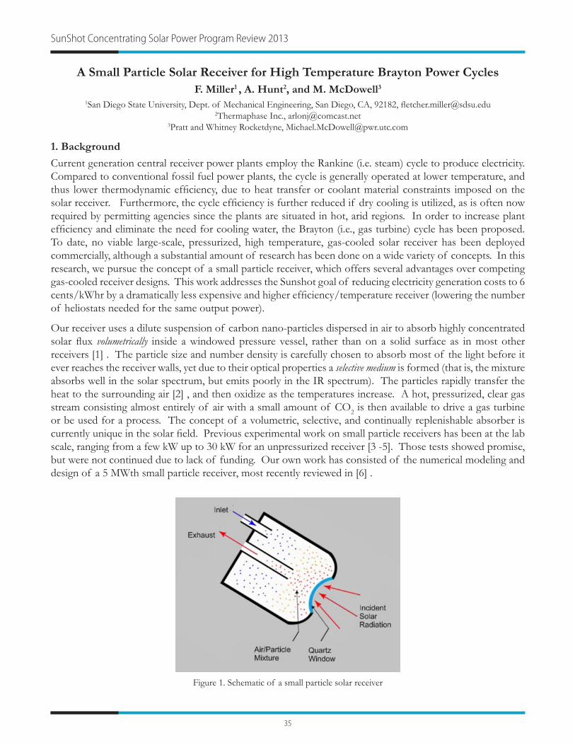
35
SunShot Concentrating Solar Power Program Review 2013
A Small Particle Solar Receiver for High Temperature Brayton Power CyclesF. Miller1 , A. Hunt2, and M. McDowell3
1San Diego State University, Dept. of Mechanical Engineering, San Diego, CA, 92182, [email protected] Inc., [email protected]
3Pratt and Whitney Rocketdyne, [email protected]
1. Background
Current generation central receiver power plants employ the Rankine (i.e. steam) cycle to produce electricity. Compared to conventional fossil fuel power plants, the cycle is generally operated at lower temperature, and thus lower thermodynamic efficiency, due to heat transfer or coolant material constraints imposed on the solar receiver. Furthermore, the cycle efficiency is further reduced if dry cooling is utilized, as is often now required by permitting agencies since the plants are situated in hot, arid regions. In order to increase plant efficiency and eliminate the need for cooling water, the Brayton (i.e., gas turbine) cycle has been proposed. To date, no viable large-scale, pressurized, high temperature, gas-cooled solar receiver has been deployed commercially, although a substantial amount of research has been done on a wide variety of concepts. In this research, we pursue the concept of a small particle receiver, which offers several advantages over competing gas-cooled receiver designs. This work addresses the Sunshot goal of reducing electricity generation costs to 6 cents/kWhr by a dramatically less expensive and higher efficiency/temperature receiver (lowering the number of heliostats needed for the same output power).
Our receiver uses a dilute suspension of carbon nano-particles dispersed in air to absorb highly concentrated solar flux volumetrically inside a windowed pressure vessel, rather than on a solid surface as in most other receivers [1] . The particle size and number density is carefully chosen to absorb most of the light before it ever reaches the receiver walls, yet due to their optical properties a selective medium is formed (that is, the mixture absorbs well in the solar spectrum, but emits poorly in the IR spectrum). The particles rapidly transfer the heat to the surrounding air [2] , and then oxidize as the temperatures increase. A hot, pressurized, clear gas stream consisting almost entirely of air with a small amount of CO2 is then available to drive a gas turbine or be used for a process. The concept of a volumetric, selective, and continually replenishable absorber is currently unique in the solar field. Previous experimental work on small particle receivers has been at the lab scale, ranging from a few kW up to 30 kW for an unpressurized receiver [3 -5]. Those tests showed promise, but were not continued due to lack of funding. Our own work has consisted of the numerical modeling and design of a 5 MWth small particle receiver, most recently reviewed in [6] .
Figure 1. Schematic of a small particle solar receiver

36
2. Objectives
The objective of this project is to design, construct, and test a revolutionary high temperature solar receiver in the multi-MW range that can be used to drive a gas turbine to generate low-cost electricity. A secondary goal is demonstrating for the first time a pressurized solar receiver with a window greater than 1 m in diameter. The proposed use for the receiver is to drive a gas turbine, but such a receiver can be used for high temperature process heat and for solar processing of fuels and chemicals. The capability of the receiver to generate pressurized (0.5 MPa), high temperature (~1000 C) air at high efficiency (~90%) will be demonstrated at the multi-megawatt level via prototype testing at the National Solar Thermal Test Facility at Sandia National Laboratory.
3. Key Findings
We have been working on the SunShot project for 6 months. In that period we have focused on further developing our receiver model, the window thermal and mechanical design, and preparing for lab-scale experiments. Our numerical model uses the commercial CFD package FLUENT to solve the mass, momentum, and energy equations for the gas flow in the receiver, combined with an in-house Monte Carlo Ray Trace FORTRAN for the radiation transfer. The previous model was 2-D axisymmetric, had an ideal (perfectly transparent) window, and used either a collimated or a diffuse (within a 45 degree cone) input. In the new model, which is currently undergoing testing, we used the legacy MIRVAL code from Sandia to determine the intensity distribution at the receiver aperture from the NSTTF heliostat field, and then trace rays in 3-D through a curved window with real quartz properties into the receiver, following them until they are absorbed or exit the receiver again. The 3-D code is coupled to a 3-D FLUENT model to predict the temperatures and velocities within the receiver. The 3-D radiation code has been successfully benchmarked against ideal solutions published in the literature (such as for gray gases in uniform temperature cylinders).
A variety of domed window shapes and thicknesses have been evaluated for mechanical stress and longevity based on Weibull statistics. The thermal loading on the glass from both the heliostat field and the re-radiation from the receiver has been calculated, and internal glass temperature and temperature gradients have been determined.
4. References
[1] A. Hunt, “Small Particle Heat Exchangers,” LBL Report 7841, 1978.
[2] W. W. Yuen, F. J. Miller and A. J. Hunt, “Heat Transfer Characteristics of a Gas-Particle Mixture Under Direct Radiant Heating,” International Communications in Heat and Mass Transfer, Vol. 13, pp. 145-154, 1986.
[3] A. Hunt and D. Evans, “The Design and Construction of a High-Temperature Gas Receiver Utilizing Small Particles as the Heat Exchanger (SPHER), Phase 1 Report, LBL-13755, 1981
[4] A.J. Hunt and C.T. Brown, Phase II Report “Solar Testing of the Small Particle Heat Exchanger Receiver,” February 1983. LBNL-15807
[5] R. Bertocchi, J. Karni, and A. Kribus, “Experimental evaluation of a non-isothermal high temperature solar particle receiver,” Energy, Vol. 29, pp. 687-700, 2004.
[6] F. Miller and A. Hunt, “Developing the Small Particle Heat Exchange Receiver for a Prototype Test,” Proceedings of the ASME 2012 6th International Conference on Energy Sustainability, Paper 91337, July 23-26, 2012, San Diego, California, USA.
Power Cycles and Thermal Receivers: Hybrid and Air Brayton

37
SunShot Concentrating Solar Power Program Review 2013
Brayton-Cycle Baseload Power Tower CSP SystemB. Treece1 and B. Anderson2
1Wilson Solarpower Corporation, 150 Lincoln St, Suite 3C, Boston, MA 02111, [email protected] Solarpower Corporation, [email protected]
1. Background
Solarized Brayton-cycle gas turbine power tower modules from 100 kWe to 5 MWe offer a CSP solution that may be able to achieve capacity factors in excess of 75% and, ultimately, LCOEs under 6 ¢/kWh in volume production. However, Brayton power towers, too, face challenges, but those challenges are technical and are achievable relatively quickly with relatively modest but adequate funding. The principal technical challenge is a breakthrough in air-heating solar receivers along with fully engineering and testing a pre-engineered, standardized, baseload power plant module. Wilson Solarpower has invented such a receiver as well as a system configuration that enables low-pressure, rather than the current small high-pressure, receivers. Also, the system’s thermal energy storage can be dry and unpressured. The result is a CSP system in which at least 80% of total system costs can benefit from cost-reductions through mass production in factories, and shipped to the site operation ready.
2. Objectives
• Phase 1: Determine whether a CSP Brayton power tower system had the potential to achieve baseload parity with coal, both LCOE and capacity factor and, if so, the ideal power size (a capacity factor of at least 75%, 85% solar, LCOEs <9 ¢/kWh adjusted for 2009$).
• Phase 2: a) Develop, build, test, and evaluate an innovative, low-pressure, air-heating solar receiver; b) Engineer a low-pressure, dry thermal storage system; and c) Cycle test Haynes 214 to be considered for a high-temperature heat exchanger.
• Phase 3: Develop, build, test, and evaluate a single power plant module.
3. Key Findings
Phase 1, completed in August 2010: A 1750-kWe power plant module in a low-pressure system configuration with a low-pressure receiver with 13 hours of dry thermal energy storage might meet or exceed DOE’s project targets for a 100 MW or greater CSP power plant (i.e., a capacity factor of at least 75%, 85% solar, LCOEs <9 ¢/kWh adjusted for 2009$). Because current Brayton power tower approaches have been limited to 100 kWe, it was determined that the best module size to develop initially in Phases 2 and 3 in order to best manage risk is 300 kWe.
Phase 2, completion in July 2013
a) Low-pressure solar receiver
The receiver was engineered in collaboration with Brayton Energy and DLR, and is based on the 100 kWe DLR high-pressure volumetric receiver. Its aperture is 1.5 m, compared with 60 cm for the DLR version. It is designed for 2200 kWth to power 300 kWe during the day and simultaneously to store 13 hours of heat to power the turbine off-sun. Inlet air is ~650C and outlet air is ~970C. Operating efficiency is expected to be greater than 85%.
The prototype is being assembled for on-sun testing at Sandia National Laboratory in mid-2013.

38
b) Thermal energy storage
The TES is being engineered in collaboration with the NorPro division of Saint-Gobain. The concept is based on an approach used by the steel refinery industry for more than 100 years in devices known as “hot stoves” or “cowper stoves”. The steel container stands vertically, is lined with insulation, and is filled with a heat storage medium such as small pieces of ceramic. The current design has a storage media bed diameter of 3.2 m and height of 7.5 m for a total volume of 61 m3. It is sized to store sufficient heat to power 300 kWe for 13 hours, i.e., a storage capacity of ~3900 kWh. During charging, a portion of the 970C air from the receiver enters the top of the storage medium and exits through the bottom at an average temperature of ~619C. During discharging, i.e., while the powering the turbine, airflow is reverse. Exhaust air from the turbine at 650C enters through the bottom and emerges from the top at an average temperature of ~936C.
c) Cycle testing of Haynes 214
Oak Ridge National Laboratory cycle-tested the Haynes 214 alloy to determine whether when used as a heat exchanger it is capable of handling the 970C exit temperatures from either the receiver or the TES. The heat exchanger transfers the heat to the turbine’s compressed air (which then powers the turbine). Metal foil thicknesses of 2 mil, 4 mil, 5 mil, 6 mil and 10 mil were tested at 950C, 1000C, and 1050C for 8000 hours: 9 hours hot, 1 hour cold, 800 cycles. The results were:
• No samples of any thickness successfully cycled at 1050C• Most foil thicknesses survive nicely at 950C• 5 mil and especially 6 mil thickness are the best performing thicknesses at 1000C
Based on initial lifetime modeling by ORNL using actual test results, the major conclusion is that 6 mil HR214 foil “optimistically can make 100,000 hours operating at 975°C.” - Bruce Pint, ORNL
Power Cycles and Thermal Receivers: Hybrid and Air Brayton
Figure 1. Air from the turbine and/or thermal storage flows around the perimeter of the receiver, enters the cavity formed by the “inlet” absorber near the front of the receiver near the quartz window, passes through the ceramic
“outlet” absorber, and exits through the rear.

39
SunShot Concentrating Solar Power Program Review 2013
Novel Dry Cooling Technology for Power PlantsC. Martin1 and J. Pavlish2
Energy and Environmental Research Center, University of North Dakota, 15 North 23rd Street, Stop 9018, Grand Forks, ND 58202, [email protected] and [email protected]
1. Background
The University of North Dakota’s Energy and Environmental Research Center (EERC) is developing a market-oriented dry cooling technology that is intended to address the key shortcomings of conventional dry cooling technologies: high capital cost and degraded cooling performance during daytime temperature peaks. The technology is applicable to all Rankine cycle-based power plants, including conventional fossil and nuclear plants as well as solar thermal systems.
Cooling the steam condenser of a solar thermal plant is a relatively more difficult design challenge compared to other power plant types. Not only are these plants sited in hot, arid locations to take advantage of the solar resource, but they are also required to run during the hottest parts of the day and are most profitable during the hottest weather, precisely when cooling system performance is taxed the most. Furthermore, solar thermal plants tend to have lower capacity factors compared to conventional baseload generation, which means that the cooling system cost must be amortized over relatively fewer operating hours each year. Finally, the most common cooling medium for power generation, water, is either limited in supply or simply not available at the locations with prime solar resources.
1.1. Conventional Dry Cooling
Dry cooling options do exist that can virtually eliminate a plant’s need for cooling water, and there are a small number of dry cooling systems in the United States, with the most common configuration being the air-cooled condenser (ACC). In these systems, steam turbine exhaust is routed directly to an ACC where the latent heat of steam condensation is dissipated to the atmosphere through the sealed walls of the condenser. The key disadvantage of conventional dry cooling is a lower return on investment; ACCs are more expensive to construct than wet recirculating cooling systems, and the performance of an ACC degrades rapidly with hot weather—often limiting plant output during times of peak demand. The cost and performance gap associated with conventional dry cooling is a costly disadvantage for plants that are required to use it because of resource limitations.
1.2. Desiccant Dry Cooling
The key aspect of the EERC’s dry cooling technology is the use of a liquid desiccant as a heat-transfer medium between a power plant’s steam condenser and the ambient air. Desiccant dry cooling (DDC) is schematically similar to a conventional wet evaporative cooling system; however, the underlying components and overall system performance are significantly different because of the hygroscopic properties of the desiccant liquid. Unlike water, the desiccant will attain a temperature and vapor pressure equilibrium with the atmosphere and can be circulated continuously without the need for makeup fluid. Direct contact exchange between the desiccant and the air enables the following key features that are beneficial for large-scale heat dissipation to the atmosphere:
• Heat transfer surface area. The surface area for heat transfer into the air with DDC is defined by the interfacial area between the air and the desiccant. Therefore, it is possible to create large heat-transfer surfaces using relatively inexpensive wetted packings or structured fill material.

40
• Integral thermal storage. Daily fluctuations in ambient temperature can cause cyclic absorption and evaporation of moisture to and from the desiccant fluid. Net heat dissipation with DDC is ultimately embodied as sensible heating of the air; however, these transient periods of moisture evaporation can be used to offset the daytime performance degradation that hinders conventional dry cooling systems. This cache of evaporative cooling is charged at night by dissipating the heat from moisture absorption in addition to the heat load from the plant.
2. Objectives
The overall objective of this Advanced Research Projects Agency – Energy-funded project is to develop and test specialized heat-exchange equipment that will transform DDC from a novel concept into a disruptive market technology. Previous development work suggests that the direct contact process between the air and the desiccant is feasible but that the success of the technology will depend on developing a heat-exchange interface between the desiccant and the power plant that can achieve specified cost and performance goals. Provided these goals can be met, Table 1 summarizes the anticipated benefits of DDC compared to state-of-the-art dry cooling for baseload plant applications.
Table 1. Anticipated performance benefits of DDC for baseload applications.
MetricState-of-the-Art,
ACCProposed,
DDCDry cooling capital cost Approximately 3 times wet
evaporative cooling1.5 times wet evaporative
coolingDay-to-night condenser temperature variation Up to 15°C 4°–7°C
Breakeven cost of water Approximately $3/1000 gallons Less than $1/1000 gallons
3. Key Findings
A preliminary analysis has been performed to evaluate possible advantages of using DDC to cool solar thermal plants in addition to baseload applications. It was hypothesized that the integral thermal storage feature of DDC could be optimized to a further extent for a solar thermal plant since there is typically no thermal load from these plants at night. The preliminary study modeled the effects of operating strategy on cooling system size. It was determined that by operating the DDC system at night to equilibrate the working fluid with cooler ambient conditions, the cooling system could be sized approximately 10%–40% smaller than an equivalent system that was operated only during power-producing periods. This reduction in system capital does come at the expense of additional fan power consumption, so a complete cost and benefit analysis is needed to determine the true value of these size reductions for the solar thermal application. However, the analysis does suggest that DDC has the potential to be a complementary cooling technology for solar thermal power plants by being able to distribute the cooling load outside power-producing periods.
Power Cycles and Thermal Receivers: Hybrid and Air Brayton

41
SunShot Concentrating Solar Power Program Review 2013
10-MW Supercritical-CO2 Turbine TestC. Turchi1, T. Held2, J. Pasch3, and K. Gawlik4
1National Renewable Energy Laboratory, 15013 Denver West Parkway, Golden, CO 80401, [email protected] Power Systems, [email protected]
3Sandia National Laboratories, [email protected] Solar, [email protected]
1. Background
The current state of the art in CSP technology is the molten salt power tower. Although power towers are capable of achieving temperatures up to 900°C, the current molten nitrate salt used as the heat transfer and thermal storage fluid is limited to temperatures less than about 600°C. An operating limit of approximately 565°C, combined with a dry-cooled steam Rankine power cycle, limits thermal-to-electric conversion efficiency to approximately 41%. Power cycle efficiency has a dramatic impact on CSP levelized cost. Higher efficiency in the power cycle reduces the size of the solar field and thermal storage system required to achieve the desired system capacity and reduces the size of the power block cooling loads. Accordingly, the US Department of Energy SunShot Initiative has set CSP power cycle goals at greater than 50% dry-cooled efficiency with a power block cost less than $1200/kW. This project will showcase the turbomachinery for a new cycle, the supercritical carbon dioxide (s-CO2) Brayton cycle, capable of achieving these objectives. This cycle has been under investigation for the past decade; researchers have modeled the basic thermodynamics of the cycle and used small test rigs to explore the behavior of s-CO2 turbomachinery and operational/control characteristics of a closed Brayton cycle. However, validation via operation of a larger-scale prototype at temperatures relevant to CSP is needed to establish the true potential of this power cycle.
2. Objectives
The goal of this project is to validate the turbomachinery and control strategies for a power cycle that has the capability to meet all of the technical targets for SunShot’s CSP power cycle and fundamentally transform the CSP industry. This project will design, fabricate, and validate an s-CO2 Brayton cycle of nominally 10 MW that is capable of operation at up to 700°C and operation under dry cooling conditions. Demonstrating turbomachinery performance at this high temperature is essential for solar applications that meet the SunShot goals, while the system scale is necessary to demonstrate the inherent efficiencies of the s-CO2 technology by using components and design features that are employed in commercial turbomachinery. The project will confirm an s-CO2 power turbine efficiency at a commercially viable level of 80% and outline the pathway to high-efficiency power cycles exceeding 50% net thermal-to-electric conversion efficiency in CSP applications.
The project is divided into three phases: (1) Design, (2) Fabrication and Installation, and (3) Operation and Simulation. Phase 1 includes the following milestones:
1.1 Alloy test matrix with recommendations for materials1.2 Test plan and draft of safe operating procedures1.3.1 Turbomachinery design package with efficiencies1.3.2 Turbomachinery design study for 100 MW scale1.4.1 Transient performance model of test loop1.5 Review commercial power cycle design1.6 Deployment roadmap to SunShot1.7 Draft NEPA assessment and timeline

42
During Phase 2 the hardware for the project will be fabricated and shipped to the test site at Sandia National Laboratories in Albuquerque, NM. The large scale of the test requires substantial infrastructure to support the operation of the commercial-design s-CO2 turbine. Following successful checks of the hardware, Phase 3 will initiate with testing of the power turbine at approximately 550°C before moving to operation with a turbine inlet temperature of approximately 700°C. No CSP source is available that can provide the required thermal input for the turbine test, and the test program will use natural gas for the heat source. Air cooling will be used, consistent with program objectives to minimize water consumption at future CSP facilities.
3. Key Findings
Corrosion testing and materials selection is underway at project partner University of Wisconsin at Madison. The initial results are consistent with prior predictions that high-nickel superalloys will be required for the high-temperature system components, but common stainless steels and lower grade carbon steel can be used for the cold portions of the cycle. Continuing analysis will better define material life and develop an understanding of corrosion mechanisms as well as a predictive model.
The piping and instrumentation framework of the test cycle is being evaluated by project partner Echogen Power Systems as part of their development of the EPS100 power system. This unit is undergoing low-temperature flow and controls tests. Concurrent with the EPS100 tests, Echogen is designing the high-temperature power turbine and the changes necessary for operation of the compressor at dry-cooled conditions. Project partner Abengoa Solar is developing specifications for the test system burner and precooler. The test unit will be gas-fired and the support infrastructure for supplying the process heat and providing cycle cooling are substantial. The analysis indicates that air cooling is a preferred option from the perspective of system cost and complexity, which is consistent and supportive of the project objective to demonstrate a cycle operating under conditions representative of dry cooling in the desert Southwest. Abengoa is also modeling CSP / s-CO2 power systems to map the deployment path of the technology into the solar industry.
Preparations continue at the test site at Sandia National Laboratories in Albuquerque. Permitting requirements have been identified and Sandia staff has determined the cost and pathway for a high-pressure gas line spur to supply the 10 MW test. Full preparations for hardware installation will commence when the project completes its Phase 1 go/no-go milestones.
Power Cycles: Supercritical Carbon Dioxide and Solid State

43
SunShot Concentrating Solar Power Program Review 2013
Development of a High Efficiency Hot Gas Turbo-Expander and Low Cost Heat Exchangers for Optimized CSP Supercritical-CO2 Operation
J. Moore1, K. Brun2, P. Bueno3, C. Kalra4, D. Hofer5, and J. Davis6
1Southwest Research Institute, 6220 Culebra Rd. San Antonio, TX 78248, [email protected] Research Institute, [email protected]
3Southwest Research Institute, [email protected] Electric Global Research Center, [email protected]
5General Electric Global Research Center, [email protected] Energy LLC, [email protected]
1. Background
In 2011, an National Renewable Energy Laboratory (NREL) report [1] completed the evaluation of a supercritical-CO2 (s-CO2) cycle for concentrated solar power (CSP) applications. The study concluded that the use of s-CO2 in a closed-loop recompression Brayton cycle offers equivalent or higher cycle efficiency when compared with supercritical- or superheated-steam cycles at temperatures relevant for CSP applications. The proposed cycle uses s-CO2 as both the heat transfer fluid in the solar receiver and the working fluid in the power block. The lower thermal mass and increased power density of the s-CO2 cycle, as compared to steam-based systems, enables the development of compact, high-efficiency power blocks that are compatible with sensible-heat thermal energy storage, and can respond quickly to transient environmental changes and frequent start-up/shut-down operations. These smaller, integrated power blocks are ideal for modular tower mounted CSP solutions in the 5-10 MW range. The study highlighted areas of uncertainty as to the high pressure required and the lack of experience with closed-loop Brayton cycles, especially with the turbo-machines required.
The team of Southwest Research Institute® (SwRI), General Electric (GE), Bechtel Marine Propulsion Corporation, and Thar Energy LLC (Thar) proposes to develop a high-efficiency s-CO2 turbo-expander for the solar power plant duty cycle profile, and to optimize novel printed circuit heat exchangers for s-CO2 applications to reduce their manufacturing costs. The scalable s-CO2 expander design and improved heat exchanger close two critical technology gaps required for an optimized CSP s-CO2 power plant and provide a major stepping stone on the pathway to achieving CSP power at $0.06/kW-hr levelized cost of electricity, increasing energy conversion efficiency to greater than 50%, and reducing total power block cost to below $1,200/kW installed.
2. Objectives
The main objective is to develop a novel, high-efficiency s-CO2 hot gas turbo-expander, optimized for the highly transient solar power plant duty cycle profile. This MW-scale s-CO2 turbo-expander design advances the state-of-the-art from a current technology readiness level (TRL) 3 (initial small-scale laboratory size testing) to a full TRL6 (MW-scale prototype demonstration). A secondary objective of this project is to optimize novel printed circuit heat exchangers for s-CO2 applications to drastically reduce their manufacturing costs. The s-CO2 turbo-expander and novel heat exchanger will be tested in a 1-MWe s-CO2 test loop, fabricated to demonstrate component performance and the performance of the optimized s-CO2 Brayton cycle over a wide range of part load conditions and during transient operations representative of a typical CSP duty cycle.

44
3. Key Findings
3.1. Heat Exchanger Design and Testing
A first prototype of the heat exchanger has been fabricated and pressure-tested successfully. Figure 1 shows pictures of this first prototype. A second prototype is currently under development and fabrication has begun using a different concept dubbed bundle leaf.
3.2. Turbo-machinery Design
Three types of turbo-machinery layouts (high-speed, geared, and low-speed) are currently being evaluated on the basis of efficiency, manufacturability, and reliability. Figure 2 shows examples of the high-speed and low-speed concepts.
3.3. Test Loop Design
Figure 3 below shows the general configuration of the test loop that will be built to test the turbo-expander and heat exchanger. To date, the operational requirements for most major components have been defined and procurement of long-lead items such as the primary heater is underway.
4. References
[1] Ma, Z., and Turchi, C., 2011, “Advanced Supercritical Carbon Dioxide Power Cycle Configurations for Use in Concentrating Solar Power Systems,” NREL/CP-5500-50787, Supercritical-CO2 Power Cycle Symposium, Boulder, CO.
Power Cycles: Supercritical Carbon Dioxide and Solid State
Figure 1. Heat exchanger prototype, as fabricated (a), and with inlet/outlet caps (b)(a) (b)
Figure 2. Examples of the Turbo-machinery Layout, (a) High-speed and (b) Low-speed
(a) (b)
Figure 3. Configuration of the Test Loop for the Turbo-expander and Heat Exchanger

45
SunShot Concentrating Solar Power Program Review 2013
Next-Generation Thermionic Solar Energy ConversionN. Melosh1 , Z.X. Shen, and K. Littau
SLAC National Accelerator Laboratory, SIMES, Stanford University, [email protected]
1. Background
Direct thermal-to-electricity conversion (TEC) via thermionic conversion has been an alluring goal for power production since the discovery of the effect by Thomas Edison in 1880. Thermionic currents are developed when there is sufficient thermal energy to overcome the electron work function and emit current across a vacuum gap. Recent advances, especially through the development of Photon Enhanced Thermionic Emission (PETE), have stimulated new interest and promise high power and efficiency as well as integration with traditional concentrated solar power. Due to their high operating temperatures, thermionic energy converters are uniquely suited for topping cycle applications and have the potential to add up to 40% to the efficiency of solar-thermal power stations (see fig. 1). Such topping cycles could almost double the electricity output of hybrid CSP systems and reduce the cost of solar-thermal electricity below that of the lowest-cost fossil fuel generated electricity.
We have demonstrated that optical illumination on a semiconductor cathode emitter can increase the emitted electron energy in a process known as photon-enhanced thermionic emission [1]. By combining this process with TEC devices, higher output voltages at lower operating temperatures can be obtained, significantly improving overall efficiency. These photon-enhanced thermionic energy converters (PTECs) have the same vacuum-gap parallel-plate architecture as a thermionic energy converter (TEC) except with a p-type semiconductor as the cathode (Figure 1). The PETE process thrives at high temperatures, and indeed improves with increasing temperature making it well suited as a topping cycle for CSP generation.
2. Objectives
This research will create a new solid-state energy conversion technology based on photon-enhanced thermionic energy converters (PTECs) which, when used as a topping cycle in concentrated solar thermal electricity generation, will enable system efficiencies in excess of 50%. The team is engaged in testing heterostructure semiconductor cathodes based on active layer absorbers such as GaAs and similar materials with the addition
Figure 1. Tandem PTEC / CSP system concept. (a) Schematic diagram showing solar illumination heating the cathode elements, creating electron emission. These electrons are harvested directly as electricity, and the ‘waste’ heat generated passed down to
a bottoming thermal cycle. (b) Diagram showing heat and electron fluxes within the system (c) Simulated efficiency of tandem system showing potential for >50% conversion efficiency.

46
of band engineered passivating layers such as GaN to demonstrate high quantum efficiency PETE emitters. The final demonstration will be an energy conversion device with a stand-alone laboratory efficiency of >15% as a significant intermediate step towards a stand-alone unit of >30% which will enable >50% combined net thermal to electric system efficiency.
3. Key Findings
PETE Model: We have constructed a PETE model which is able to calculate the stand-alone and tandem performance of a CSP PETE based system. In Fig. 2a and b, we show the optimized PETE power conversion efficiency as a function of emitter band gap and anode (collector) work function. We have further extended this model to include non-idealities such as interface recombination in the cathode and loss of heat through electrical leads, which in the future will allow us to bridge the gap between idealized theoretical efficiencies and realistic devices.
Passivated Gallium Arsenide: Trivalent metal oxides should provide excellent passivation for GaAs with aluminum oxide as a natural first choice. Coatings of Alumina on GaAs are thought to heal As-As dimers even after a single monolayer. We report the first investigations of ALD alumina passivation for GaAs PETE structures which are also likely to be able to act as a diffusion barrier for Cs migration into the GaAs.
Mixed Composition Nitrides: InGaN has been previously identified as a material suitable for high temperature operations. Experiments in our laboratory have shown surface compositional stability in vacuum of as high as 40% In content InGaN up to at least 600 C in heated XPS testing. In addition we have used GaN/InGaN/GaN single quantum well (QW) structures as a model system for InGaN PETE devices. These structures provide a means for stabilizing and passivating the high In containing absorber layers while demonstrating high quantum efficiency of electron emission.
4. References
[1] J. W. Schwede, I. Bargatin, D. C. Riley, B. E. Hardin, S. J. Rosenthal, Y. Sun, F. Schmitt, P. Pianetta, R. T. Howe, Z.-X. Shen, and N. A. Melosh, “Photon Enhanced Thermionic Emission for Solar Concentrator Systems,” Nat. Mater., 2010, 9, 762–767. DOI: 10.1038/nmat2814
Figure 2. a) Calculated PETE efficiency at anode temperature of 650C vs. cathode bandgap showing optimal power conversion at Eg of approximately 1.4 eV at 1000x solar concentration. b) Power conversion efficiency vs. anode work function for three anode temperatures showing strong dependence. Anode work function should be optimized for different local Heat Transfer
Fluid temperatures in receiver to maximize energy conversion.
Power Cycles: Supercritical Carbon Dioxide and Solid State

47
SunShot Concentrating Solar Power Program Review 2013
Concentrated Solar Thermoelectric PowerG. Chen1, Z.F. Ren2, K. McEnaney3, D. Kraemer4, L. Weinstein5, S. Boriskina6, Q. Jie7, T. Dahal8,
F. Cao9, and W.S. Liu10
1Massachusetts Institute of Technology, Cambridge, MA, [email protected] of Houston, [email protected]
3Massachusetts Institute of Technology, [email protected] Institute of Technology, [email protected] Institute of Technology, [email protected] Institute of Technology, [email protected]
7University of Houston, [email protected] of Houston, [email protected]
9University of Houston, [email protected] of Houston, [email protected]
1. Background
Thermoelectric power generation relies on the Seebeck effect in solid-state semiconductor materials to convert directly thermal energy into electricity, and has been explored for waste heat recovery, micro-power applications, and deep space missions. We have recently demonstrated solar thermoelectric generators (STEGs) which can achieve 4.6% efficiency under AM1.5G conditions without any optical concentration [1], where solar radiation is used to generate the temperature difference across the thermoelectric generator. Such STEGs have three major advantages: similar to other CSP systems, they can capture the entire solar spectrum; they can incorporate principles of thermal mass to eliminate short-term power fluctuations and to act as base load power; and they have no moving parts.
2. Objectives
This seed project aims to prove the concept of a STEG which uses concentrated solar power. Our modeling suggests that with modest optical concentration a solar thermoelectric generator should be able to reach 10% solar-to-electrical system efficiency. This is double the previous highest reported STEG efficiency. In order to prove this technology and reach this efficiency, we need to achieve the following goals:
• Develop a detailed model so that the system can be optimized• Create effective electrodes for the thermoelectric legs that are mechanically stable and have an interfacial
contact resistance below 10 μΩ•cm2
• Develop an optical system comprising a concentrator, cavity, and selective surface to reduce the effective emittance to less than 10% at 500 °C
3. Key Findings
In the first six months of our project, our team has made significant progress toward the three major goals. We have developed a detailed model to predict the performance of the thermoelectric generator at the core of the STEG. The model incorporates the temperature-dependent properties of the thermoelectrics and the electrodes. It also takes into account the parasitic radiation losses and contact resistances that degrade the device performance. The model predicts a generator efficiency of 11.6% with a two-stage device built on skutterudite and bismuth telluride thermoelectric materials that we fabricate (Fig. 1).
However, it is difficult to make electrodes for skutterudites and bismuth telluride compounds because they are low surface energy materials. The high temperatures and the thermal cycling of the application also make developing good thermal, electrical, and mechanical contact challenging. In addition, the structure of any interface usually requires a diffusion barrier to prevent detrimental doping of the thermoelectrics. We have begun by developing the contact system for our skutterudite thermoelectrics. We have identified a

48
composition suitable for the n-type skutterudite and a composition for the p-type skutterudite. Both these compounds have high electrical and thermal conductivity, have complementary Seebeck coefficients, and form a low contact resistance interface with the targeted skutterudite.
Radiation loss from the absorber of a STEG can become very large at high temperatures, thus limiting the operating regime and maximum efficiency of the system. We have designed a novel optical cavity and fabricated solar selective surfaces. Our modeling shows that by combining the cavity design with selective surfaces, low emittance can be achieved. How to measure the emittance of selective surfaces is another challenge. Typically the emittance is characterized by measuring reflectance at room temperature at one incident angle, and then extrapolating these data to predict high-temperature heat loss. This large uncertainty regarding the precise value of the surface emittance at high temperatures prevents proper system optimization. We have developed an accurate high-temperature direct measurement of the radiation loss from a surface to reduce this uncertainty. Figure 2 shows the system in use, as well as measured emittance values with error bars for a variety of surfaces.
4. References
[1] Kraemer D., Poudel B., Feng H.-P., Caylor J. C., Yu B., Yan X., Ma Y., Wang X., Wang D., Muto A., McEnaney K., Chiesa M., Ren Z., and Chen G., 2011, “High-performance flat-panel solar thermoelectric generators with high thermal concentration.,” Nature Materials, 10 (7), pp. 532–8.
Power Cycles: Supercritical Carbon Dioxide and Solid State
Figure 1. Schematic of concentrating STEG with optical cavity.
Figure 2. Emittance measurement of selective surface, and data for various surfaces.

49
SunShot Concentrating Solar Power Program Review 2013
High Temperature High Efficiency Solar Thermoelectric Generators (STEG)D.S. Ginley1, E.S. Toberer1,2, C.E. Kennedy1, G.J. Snyder3, S.A. Firdosy4, B. Nesmith4,
A. Zakutayev1, A. Goodrich1, J. Netter1, M.H. Gray1, M.L. Olsen1, P.F. Ndione1, E.L. Warren2, L.L. Baranowski2, and P.A. Parilla1
1National Renewable Energy Laboratory, Golden, CO 80401 2 Colorado School of Mines
3 California Institute of Technology 4 Jet Propulsion Laboratory, California Institute of Technology
1. Background
We report on a recently funded project with the specific goal to demonstrate a 15% efficient STEG prototype and develop economic models to confirm their commercial viability. A STEG is a solid-state heat engine that converts sunlight directly into DC electricity through the thermoelectric effect. STEGs consist of three subsystems: the solar absorber, the thermoelectric generator (TEG), and the heat management system (insulation, heat exchanger, etc.) as shown in Fig. 1a. In 2011, a laboratory-scale STEG prototype demonstrated 4.6% efficiency without optical concentration at 200ºC [1]. The reasons for low STEG efficiencies come from two sources: low Carnot efficiency due to the relatively small temperature drop across the devices and losses inherent to the then state-of-the-art thermoelectric materials. Thus, increasing temperature differences and improving materials is paramount. Thermoelectric material performance is evaluated by a figure of merit (ZT) [2]. A perfect thermoelectric material has an infinite ZT and would correspond to the thermodynamic limit (Carnot). However, the interdependent nature of the relevant material properties makes achieving high ZT challenging. To date, commercial thermoelectric materials have ZT values less than 1, but the last decade has seen tremendous advances in thermoelectric performance and ZT values are approaching 2 (Fig. 1b) and there are reports of ZT>2 [2]. With these new materials, TEG efficiencies have progressed rapidly (Fig. 1c).
The selective absorber is also critical for high efficiency and it absorbs the concentrated solar flux and creates the hot side temperature while minimizing the blackbody radiative losses at the infrared wavelengths. In an ideal selective absorber, the absorptivity takes the form of a step function, in which the step from zero to one is located between the blackbody and solar flux maxima with the location of the step-edge called the cutoff energy (Fig. 1d).
2. Objectives
Achieving low cost and higher efficiency in the conversion of solar energy to electricity is part of the overall SunShot goals. Recently new thermoelectric conversion materials have potentially made Solar Thermal Electric Generation possible at efficiencies high enough to be a viable technology. The ultimate objective of this one-year project (start date Feb., 2013) is to demonstrate the feasibility of high temperature, high efficiency STEGs by demonstrating 15% device efficiency and developing economic models for STEGs that demonstrate the potential utility, deployment strategy and commercialization potential of the technology.
Figure 1. a) STEG diagram {1-Optical concentration. 2-Thermal absorber. 3-Thermoelectric module. 4-Cooling system. 5-Vacuum encapsulation.}[3]; b) ZT vs. T for various materials [3]; c) TEG efficiency vs. year; d) ideal selective absorber with
solar and blackbody spectrums [3]

50
3. ApproachTo produce a high-efficiency STEG, several state-of-the-art technologies must be integrated and include the selective absorber, the TEG, and heat management. NREL has a concerted effort toward improving and developing selective absorber technology. NREL researchers have modeled a multi-layer solar-selective coating based on high-temperature oxidation-resistant materials that met the STEG selection criteria and predicted performance better than any commercially available product with absorptivity = 0.959 and emissivity = 0.071 at 450°C and anticipated oxidation resistance of up to 1200 °C.
The next-generation materials for TEGs, which are being developed solely at JPL and which have the potential for 15% STEG efficiency, will be optimized for use in a STEG application. These materials are already being extensively validated by NASA-JPL for performance and reliability in radioisotope thermoelectric generators (RTGs) for spacecraft applications. From these advanced materials, JPL has been constructing, testing and analyzing segmented couples for their next-generation RTGs. For the n-type leg, they are segmenting skutterudite/La3Te4 and the p-type leg is based on skutterudite/Yb14MnSb11. JPL has been able to go from new materials to mechanical and lifetime testing of segmented couples in just four years. This commitment paid off in 2011, with the highest efficiency generator ever reported: 15% efficiency across a 1000-200°C (hot side/cold side) temperature range [4].
The TEG, selective absorber and thermal management components will all be integrated together to form the STEG device. There are several issues that will need addressing within this effort: a) controlled and efficient heat flow to maximize exergy and minimize heat losses, b) materials compatibility and stability, with respect to both the high temperatures and to each other, and includes thermal expansion mismatch and chemical stability, c) component response to transient thermal conditions, and d) optimization of the electrical path to minimize electrical losses especially at the high temperatures. Developing a successful STEG device will require attention to all these issues, and this task will rely heavily on the STEG optimization modeling [3].
We will test STEGs at NREL’s high flux solar furnace (HFSF) and perform analysis of parasitic losses and lifetime analysis to optimize prototype operation. NREL’s 10-kilowatt HFSF consists of a tracking heliostat and 25 hexagonal mirrors to concentrate solar radiation and provides flux at 2,500 suns. To reduce such high concentration to required 100-1000x levels, we will use additional optics to optimize the coupling between the HFSF and the STEG device.
NREL Strategic Energy Analysis Center has world-class capabilities, in the areas of grid integration, resource assessment, and manufacturing cost analysis. We will leverage these capabilities in order to quantitatively assess the economic performance of the STEG device, and to develop appropriate technology performance, device-cost, and system design parameters, as has been done by the NREL analysis team for PV conversion technologies. The analysis team will work with the technologists and industry to determine the optimal configuration of a STEG system that minimizes LCOE by considering different possible STEG applications, such as stand-alone power generation, integration as a topping cycle in CSP, and alternative system configurations (e.g. troughs, towers, dishes etc.).
4. AcknowledgementsAdvanced Research Projects Agency-Energy, DOE, Award Number DE-AR0670-4918. NREL’s prime contract award number is DE-AC36-08GO28308.
5. References
[1] Kraemer, D. et al. Nature Materials 10, 532-538 (2011).
[2] Snyder, G.J., Toberer, E.S., Nature Mater., 7, pp. 105-114 (2008)
[3] Baranowski, L.L., Snyder, G.J., Toberer, E.S. Energy Env. Sci. 5, 9055 (2012)
[4] 15% efficiency from JPL, J.P. Fleurial et al., International Conf. on Thermoelectrics, Traverse City, MI (2011)
Power Cycles: Supercritical Carbon Dioxide and Solid State

51
SunShot Concentrating Solar Power Program Review 2013
Flexible Assembly Solar TechnologyE. Toister1 and B. Koretz2
1BrightSource Energy, Inc., 1999 Harrison St., Suite 2150, Oakland, CA 94612, [email protected] 2BrightSource Energy, Inc., [email protected]
1. Background
Construction of a solar collector field is the largest single component of the levelized cost of energy (LCOE) generated by power tower facilities. A significant portion of the solar field construction cost derives from the current method used to assemble and install heliostats. In the current process, the mirrors are assembled on-site at a temporary special-purpose facility known as the Heliostat Assembly Building (HAB). The mirror assemblies are then stored on-site until they can be transported to the collector field and mounted on steel pylons. The construction of what is in effect an assembly factory adds significant costs to the CSP project and protracts its construction phase. Also, the money and the time required for HAB construction and its permitting procedures need to be invested long BEFORE the actual CSP construction project begins.
Several approaches can be considered for reducing these construction costs:
• Modification of the heliostat design for minimizing the required infrastructure and ground preparation• Supply chain optimization for shifting, as much as possible, the heliostat assembly process to a backend
assembly facility with automated equipment and low production costs per heliostat • Optimization of the onsite assembly work and gear for minimizing man-hours needed for heliostat
assembly and installation • Minimization of onsite assembly facility for reducing the associated permitting and construction costs
The first two approaches have been tested and demonstrated successfully in the industry. These approaches, however, carry a significant penalty in terms for design constraints forcing the heliostat size down, which in turn incurs increased cost in terms of the number of drive systems required to point the mirrors to the correct position per square meter of mirror.
The approach taken by BrightSource and implemented in the FAST project requires minimal heliostat design changes for moving a significant part of the assembly work to an offsite facility while still not compromising on the heliostat size. In addition, onsite assembly processes will be optimized to enable both low equipment cost and setup time and increased assembly throughput. The equipment’s mobility will enable it to be used in multiple projects thus reducing the cost per project.
The novelty of the proposed project lies in the application of automation processes to solar project site conditions in order to drive down costs of Solar Field assembly. The novelty of this method extends to the integrated design of the heliostat itself, which is modified to facilitate FAST assembly. This project proposes a novel method of constructing low-cost collectors that “lend themselves to automated manufacturing, minimal field grading and site preparation, and rapid installation”.
2. Project Objectives
BrightSource’s research objective is to design, build, and demonstrate a Flexible Assembly Solar Technology (FAST) system that will substantially reduce the cost and time associated with construction of a solar field and will enable achieving the SunShot Initiative’s target cost of $75/m2 for installed solar field. FAST will accelerate the heliostat assembly and field installation processes by combining elements of both functions on a single platform with direct access to the solar collector field. Figure 1 is a three-dimensional perspective view of the FAST platform.

52
With FAST, preliminary assembly of mirrors with their structural support elements will take place at a centralized off-site facility capable of supplying multiple CSP projects, rather than at an on-site facility. An automated, transportable FAST platform located on-site will then perform final assembly of these partially assembled mirrors and deliver them into the solar field for final installation. By dispensing with the HAB, FAST will substantially reduce solar field construction time and cost, reduce the need for on-site storage, and avoid costs related to permitting, construction, maintenance, operation and demolition of the HAB. The FAST process will also allow flexible deployment to multiple power tower sites in accordance with project design and schedules, thus eliminating the production limits associated with the HAB assembly facility and enabling breakthrough performance improvements. In addition, FAST will be designed to support a next-generation heliostat design, thereby ensuring further cost reductions.
3. Key Findings
Following an extensive product specification process the following understandings have been reached and are being implemented in the FAST design:
• The FAST cell is both a complex multi-disciplinary machine and a manufacturing line. The virtual production floor, on which the FAST cell is located, extends backwards to the mirror assembly facility (MAF). At the MAF, the subassembly called “Mirror Assembly” is prepared and forwarded to the actual solar collector field. The mirror assembly is one of the components used in the FAST cell for creating a heliostat reflector. Heliostat reflectors are then installed on the metal pylons. As such, the production floor spans multiple locations and presents considerable challenges in terms of material flow.
• The heliostat design needs to be optimized and fine-tuned for the required production quantities and the supply chain restrictions. Subassemblies need to be defined in accordance with the capabilities and eventual design of the FAST platform.
Solar Collectors: Manufacturing
Figure 1. 3D Conceptual Layout.

53
SunShot Concentrating Solar Power Program Review 2013
Material and Labor Efficiency with Suspension Heliostat™W. Bender1, N. Hine2, and D. Schneider3
1Solaflect Energy, 1190 Turnpike Road, Norwich, VT, 05055, [email protected] Energy, [email protected]
3Solaflect Energy, [email protected]
1. Background
The Suspension HeliostatTM is a game-changing innovation that dramatically reduces the material used in a heliostat, and as a result leads to a dramatic cost reduction. Typical heliostat designs utilize a central pedestal with a two axis (azimuth and elevation) drive system located at the top of the pedestal. The drive system in turn is attached to a horizontal torque tube that is rotated to control the elevation of the heliostat. Some type of truss system is attached to the torque tube, to which the mirrors are attached and canted. This design strategy is analogous to that of a truss bridge.
In contrast, the Solaflect Energy heliostat (Figure 1) is built with a design strategy that is analogous to a suspension bridge, and we therefore call the design a Suspension HeliostatTM. The design utilizes a tension-compression system wherein the tension elements are independent and separate from the compression elements. The key feature of the design is that a compression element is perpendicular to the mirrors and penetrates through the center of the entire mirror plane. The mirrors are held in place and stabilized at each corner with tensioned steel cables attached to either end of the compression element. One set of cables extends in front of the mirrors, and the other set of cables behind the mirrors.
The standard Suspension HeliostatTM design utilizes 16 square mirror facets, arranged in a four by four matrix, although a 36 facet heliostat has also been built and tested. For the 16 facet heliostat, there are 25 corner points, one of which is centrally located. The mirrors are held in place by small connectors at the corners of the mirrors that in turn are held in place by the cables. In the 16 facet design, there are 5 sets of different cable lengths in the front of the heliostat, and 5 corresponding sets of cables in the rear of the heliostat, all of which are attached to the compression element either in the front or rear of the heliostat, respectively.
The rear compression element resists most of the forces imparted on the heliostat facets by wind and gravity. Forces on the front compression element are transmitted through the cables to the rear compression element, thus preventing it from bending. The front
compression element is thin to minimize blocking of the mirrors. There is some minimal shading of the mirrors which totals 1-2% including both the direct solar radiation and its reflection towards the receiver. This slight reflectivity performance penalty is dramatically outweighed by the reduction in material required and the performance benefits. The mirror facets do endure a modest compression load, but even 4 mm glass has sufficient structural strength in itself to support this load. Most composite or laminated panels can easily be designed to meet the structural requirements of the facets.
Figure 1. Front View of Suspension HeliostatTM
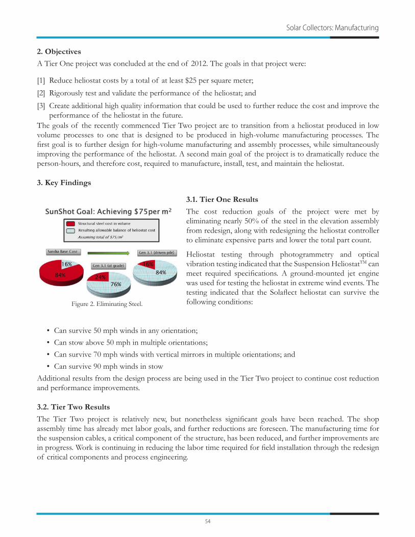
54
2. Objectives
A Tier One project was concluded at the end of 2012. The goals in that project were:
[1] Reduce heliostat costs by a total of at least $25 per square meter;
[2] Rigorously test and validate the performance of the heliostat; and
[3] Create additional high quality information that could be used to further reduce the cost and improve the performance of the heliostat in the future.
The goals of the recently commenced Tier Two project are to transition from a heliostat produced in low volume processes to one that is designed to be produced in high-volume manufacturing processes. The first goal is to further design for high-volume manufacturing and assembly processes, while simultaneously improving the performance of the heliostat. A second main goal of the project is to dramatically reduce the person-hours, and therefore cost, required to manufacture, install, test, and maintain the heliostat.
3. Key Findings
3.1. Tier One Results
The cost reduction goals of the project were met by eliminating nearly 50% of the steel in the elevation assembly from redesign, along with redesigning the heliostat controller to eliminate expensive parts and lower the total part count.
Heliostat testing through photogrammetry and optical vibration testing indicated that the Suspension HeliostatTM can meet required specifications. A ground-mounted jet engine was used for testing the heliostat in extreme wind events. The testing indicated that the Solaflect heliostat can survive the following conditions:
• Can survive 50 mph winds in any orientation;• Can stow above 50 mph in multiple orientations;• Can survive 70 mph winds with vertical mirrors in multiple orientations; and• Can survive 90 mph winds in stow
Additional results from the design process are being used in the Tier Two project to continue cost reduction and performance improvements.
3.2. Tier Two Results
The Tier Two project is relatively new, but nonetheless significant goals have been reached. The shop assembly time has already met labor goals, and further reductions are foreseen. The manufacturing time for the suspension cables, a critical component of the structure, has been reduced, and further improvements are in progress. Work is continuing in reducing the labor time required for field installation through the redesign of critical components and process engineering.
Solar Collectors: Manufacturing
Figure 2. Eliminating Steel.

55
SunShot Concentrating Solar Power Program Review 2013
Advanced Reflective Films and Panels for Next Generation Solar CollectorsA. Molnar and M.B. O’Neill
3M Company, 3M Center Building 235-2S-27, St. Paul, MN 55144
1. Introduction
The SunShot Department of Energy initiative targets a cost of $75/m2 for the installed cost of the solar collector field of a CSP (Concentrating Solar Power) system. This aggressive target is necessary in order to meet the stated objective of delivering solar energy at $0.06/kW-hr. The “Next Generation Solar Collectors for CSP” aims to achieve these targets by the development of new solar collector base technologies: advanced reflective films, optically accurate reflector panels, low cost space frames, adaptive optics and accurate tracking drives. These unique elements will be combined to build a heliostat which will be ultimately tested at the Sandia National Solar Thermal Test Facility. This presentation covers the progress on two elements: advanced reflective films and optically accurate reflector panels
2. Project Approach
Multilayer optical films, consisting of several hundred layers of alternating polymer layers, are used to increase the total solar reflectance of the reflector. Lab scale extrusion trials were used to identify compatibility of material sets and prepare samples for subsequent optical and weathering studies for polymeric solar mirror films. Successful material sets were further investigated with pilot scale trials.
Optical and weathering studies were initiated on samples.
The reflector panel, called the MTTS (Mini-Truss Thin Sheet), was used as the starting point for looking at the material cost envelope of these panels. Lower cost adhesives were evaluated and tested. Preliminary analysis of surface smoothness and scattering were taken as part of the evaluation matrix. The surface characterization tool, VSHOT (Video Scanning Hartmann Optical Test), was used to look at slope error for some MTTS panels.
3. Results
3.1. New reflective films development
Multilayer optical film (MOF) mirrors have been fabricated to enhance the solar weighted hemispherical reflectance.
Reflectance spectrum of a new MOF mirror (blue) compared to the original target (red). The new MOF mirror has a wider reflectance spectrum which will result in higher total solar reflectance when enhanced with additional material layers.

56
Solar Collectors: Manufacturing
A pilot scale extrusion experiment was completed to create wider reflectance band material (shown in blue above) and samples were produced for manufacturing trials. These samples are still being processed.
3.2. New panel configuration and materials
A preliminary cost analysis was completed for the MTTS. The heat map matrix below shows the cost reduction potential (as a % of cost as compared to the aluminum construction shown in the upper left). The squares with red borders are the areas of interest in terms of cost reduction (< 50% of cost of comparative).
We have completed the first cycle of weathering (UV chamber for 400 hrs) on the lower cost adhesives X & Y, and comparative adhesive A. The tests were done on assembled (glued) aluminum based MTTS panels. Peel testing was done to evaluate the performance of the adhesives after weathering. The weathering set included two different adhesive lay-down profiles (1 & 2). A statistical sample set was tested and it was found that in all cases the lower cost developmental adhesives (X & Y) outperformed the incumbent adhesive “A”. Box plots are shown below for the bond strength of the samples after UV weathering:
This report was prepared as an account of work sponsored by an agency of the United States Government. Neither the United States Government nor any agency thereof, nor any of their employees, makes any warranty, express or implied, or assumes any legal liability or responsibility for the accuracy, completeness, or usefulness of any information, apparatus, product, or process disclosed, or represents that its use would not infringe privately owned rights. Reference herein to any specific commercial product, process, or service by trade name, trademark, manufacturer, or otherwise does not necessarily constitute or imply its endorsement, recommendation, or favoring by the United States Government or any agency thereof. The views and opinions of authors expressed herein do not necessarily state or reflect those of the United States Government or any agency thereof.

57
SunShot Concentrating Solar Power Program Review 2013
Low-Cost, Light Weight, Thin Film Solar Concentrator G. Ganapathi1 , A. Palisoc2, B. Nesmith3, G. Greschik4, K. Gidanian5, and A. Kindler6
1Jet Propulsion Laboratory, California Institute of Technology, 4800 Oak Grove Drive, Pasadena, CA 91109, [email protected]
2L’Garde, Inc., [email protected], [email protected]
4TentGuild Eng. Co, [email protected] Corp, [email protected], [email protected]
1. Background
This research addresses a cost barrier towards achieving a solar thermal collector system with an installed cost of $75/m2 and meet the Department of Energy’s (DOE’s) performance targets for optical errors, operations during windy conditions and lifetime. Current concentrators can cost as much as 40-50% of the total installed costs for a CSP plant. In order to reduce the costs from current $200-$250/m2, it is important to focus on the overall system. The reflector surface is a key cost driver, and our film-based polymer reflector will help significantly in achieving DOE’s cost target of $75/m2. The ease of manufacturability, installation and replacement make this technology a compelling one to develop. This technology can be easily modified for a variety of CSP options including heliostats, parabolic dishes and parabolic troughs.
2. Project Objectives
The specific project objectives are: 1) design and development of a mirror module using an inexpensive reflective metalized polymer film bonded onto a light-weight structural polyurethane rigid foam support, 2) design and development of a low cost non-traditional mirror module support structure, 3) selection of low cost drive components and associated control system, 4) design, integration and testing of a low cost concentrator, and 5) cost analysis of the proposed system to demonstrate $75/m2 collector system DOE target. The project will be accomplished in a partnership between JPL and L’Garde over a period of three years.
3. Key Findings
The project start was delayed from Oct ’12 to Jan ’13 due to interagency agreement issues. Weekly meetings between JPL and L’Garde have been on-going and significant progress towards some of the key elements of Phase 1 identified earlier – facet design optimization, foam material selection, metallized film selection, concentrator performance optimization.
3.1. Facet Design Optimization
Being in the early design phase, several large and small heliostat design options are being considered independently by JPL and L’Garde keeping the core requirements for performance under winds and cost. The down selection of the final designs will be done in the next quarter. One proposed large heliostat concept is shown in Figure 1 which meets several of the requirements. Only the heliostat design is shown below.
The heliostat (100 m2) shown in Fig 1 consists of 36 sub-facets (1.67mx1.67m) which can be bowed in two directions like a kite using guy wires. This allows for control of the heliostat focal point by appropriate tensioning of the guy wires. In addition, the facet mass and costs can be significantly lowered by allowing the sub-facets which are attached along one edge to the horizontal support tubes to “give” in windy conditions with magnet latching and springs to detach and snap back.

58
Solar Collectors: Manufacturing
3.2. Structural Foam Selection
Structural foam selection has been initiated and over six potential candidates have been identified. In particular, the 3MTM’s Reinforced Polyurethane Foam and Dow’s BETAFOAMTM used as structural foam for automotive applications look promising and discussions with the vendors have been initiated. A simple model has been developed to determine required foam thickness to withstand operating winds of 35 mph and meet 1 mrad pointing error due to the between 27 mph and winds [value derived from DOE FOA]. Based on discussions with JPL material experts, ASTM standards D3574, D638 and D790 have been identified as potentially being required ones for foam testing and procurements.
3.3. Silverized Film Selection
In the proposal, ReflecTec silverized film was identified for the project. Since then, materials like 3MTM’s 1100 film were identified as alternatives. Both film samples were procured and will be tested for optical performance. The standard ASTM E903 has been obtained.
3.4. Concentrator Performance Optimization
Prior studies have indicated LCOE is best optimized when larger heliostats (~ 100 m2) are chosen. However, new designs such as eSolar seem to indicate that with rapid drops in prices in actuators, etc., it might be feasible to reduce LCOE with smaller heliostats. Our project approach is to design heliostat sub-facets that can be used for both large as well as small heliostats. In order to meet this ambitious but reasonable goal, the team is looking to optimize the sub-facet dimensions. One major driver is the error budget flow down to the sub-facet level where a smaller size heliostat may be beneficial. The error allocation for surface irregularities and stiffness of the foam itself will drive the foam thickness requirements which will impact the total cost. The team is in the process of formulating the problem and using tools like SolTrace and DELSOL 3 for heliostat level and field level studies to identify the best selection of sub-facet parameters, heliostat design and field layout.
Figure 1. Heliostat (JPL-L1) with magnetically latched spring loaded hinged facets.

59
SunShot Concentrating Solar Power Program Review 2013
Advanced Manufacture of ReflectorsR. Angel
University of Arizona, Steward Observatory, 933 N. Cherry Ave., Tucson, AZ 85721, [email protected]
1. Background
CSP reflectors most commonly use self-supporting, back-silvered glass mirror panels, proven to have 20-year field life by use in trough solar plants. Cylindrically curved panels in these plants are typically 1.65 m square and 4 mm thick glass, rigid enough so they can be simply and easily attached to a lightweight backing structure with just 4 supporting nodes for each panel. The present price for panels made by Rioglass Solar at a factory volume of 2.5 million m2/year is $35/m2. For a nominal 20% conversion efficiency, this corresponds to 500 MW/year and $0.175/W.
Our project is aimed at improved manufacturing technology for self-supporting mirrors. Our primary innovation is to shape the glass by molding rather than bending. The fundamental advance being targeted is improved optical quality and versatility, in terms of the variety of shape of the mirrors, in a method with the potential for reduced manufacturing cost. A secondary advance being targeted is higher reflectivity and resistance to soiling. Both advances will result in higher efficiency, in terms of power output per unit reflector area, and thus lower field collector costs.
2. Objectives
The major objective of the project is to demonstrate that a high-accuracy glass shaping process can be implemented in a process fast enough for high-volume commercial production. A molding method of high accuracy and versatility of shape has already been demonstrated at the University of Arizona, but its 5-hours shaping cycle is too slow for economical commercial production. A new shaping furnace is being built for rapid molding. Heating will be by thermal radiation absorbed directly into the glass, and fast cooling will be by forced convection with air at room temperature. A major milestone scheduled for the end of the first year, July 2103, is to complete a new furnace incorporating these features, and to initially demonstrate shaping of full sized mirrors (1.65 m x 1.65 m) in a 15 minute cycle. The final performance objectives include:
• Optical accuracy of 2mR RMS (slope error 1 mR rms)• Sustained reflectivity of 95%• Reduced cost in high volume (~$20/m2 vs. present cost of $35/m2)
3. Key Findings
We have completed thermal and structural analysis and design of the furnace and mold for fast shaping. The analysis method has been validated by lab tests with a subscale furnace of both the furnace components and the complete shaping process. On the basis of these successful results, construction of the full-scale mold and furnace has been started.
An important finding from the thermal analysis has been a major design change for the slump mold. It was baselined as having the same “egg crate” honeycomb structure as used previously. A new design has been devised that largely avoids the high stresses and shape instability that would be caused in a honeycomb structure by rapid thermal cycling. Residual thermal deformations are expected to be accurately reproduced when a given thermal cycle is repeated, and will be corrected by re-machining or lapping the mold.
The furnace is being built with radiant heaters in the lid, specially designed to radiate at a relatively cool 900 °C, for maximum absorption by the glass. The heater design has been prototyped and validated in a single-

60
panel test furnace. The radiant heating part of the thermal cycle has been optimized by tests in this furnace. Figure 1 shows slope measurements of 300 mm square test glass samples, shaped on a mold with 1.7 m focal length. The x and y slope maps are for two replicas made with the same thermal cycle with a heating interval lasting 200 seconds. The absolute rms errors at 0.5 – 0.6 mrad are less than half those of current commercial production. The difference in the successive replicas, which sets the lower bound, is 0.3 mrad rms. When the full size furnace is placed into operation this summer, we hope to see similarly high accuracy carried over to the full 1.65 m size.
In other aspects of the project, we have designed and are building novel equipment for rapid in-process metrology of full sized replicas. We have also studied in some depth the limits to reflectivity set by chemistry for float and drawn glass manufacturing processes, and the detailed requirements for applying and processing antisoil coatings so as to preserve anti-soiling advantages through the hot-shaping cycle. We have also set up a field reflectivity testing program to monitor the rate of soiling at the University of Arizona Tech Park Solar Zone, where Tucson Electric Power (TEP) is completing a CSP facility.
The PI and co-investigators Blain Olbert and Thomas Stalcup acknowledge valuable help in this project from RioGlass Solar, REhnu Inc. and TEP, all matching industrial partners.
Solar Collectors: Optics
Figure 1. Surface maps of test slump replicas obtained from CMM scans
Replica 1 x-slope error (0.48
mR rms)
Replica 2 x-slope error
(0.50 mR rms)
y-slope error (0.61 mR rms)
y-slope error (0.60 mR rms)

61
SunShot Concentrating Solar Power Program Review 2013
Development of a Low Cost Ultra Specular Advanced Polymer Film Solar ReflectorG. Jorgensen1, A. Harant2, K. Wagner3, R. Gee4, and M. DiGrazia5
1SkyFuel, Inc. 18300 West Highway Arvada, CO 80007, [email protected], Inc., [email protected]
3Red Spot Paint and Varnish Co., Inc., [email protected], Inc., [email protected]
5SkyFuel, Inc., [email protected]
1. Background
Low-cost reflectors are a critical prerequisite to achieve the aggressive CSP goals of the SunShot Initiative. A variety of mirror types have been developed and used for solar collector applications. These include glass, front surface aluminum, and polymer film reflectors. Advanced thin-film reflectors offer a technology pathway that demonstrates distinct advantages over other types of mirrors, including light weight, low-cost, high design flexibility, unbreakability, and ease of transportation and field installation. This project involves the development of an ultra-specular advanced (USA) polymer-based front surface reflector (FSR). The solar industry has sought a viable silver FSR for decades but has been unsuccessful because adequate protection against reflectance loss could not be provided. Building upon the development of SkyFuel’s current commercial ReflecTech®PLUS Mirror Film (RTMF+) product, we now have the expertise to develop and commercialize FSR technology. The new construction will incorporate two new innovations to improve specular reflectance. First, the reflective silver layer will be front surface, which improves reflectance because there are fewer layers to absorb or scatter sunlight. Second, a UV-curable abrasion resistant coating (ARC) positioned at the outer surface of the reflector layer will be formulated to reduce absorption and further increase reflectance.
2. Objectives
A primary objective of this project is to develop a high-performance polymer film reflector having an increased solar-weighted hemispherical reflectance (SWHR) of ~1% compared with existing state-of-the-art polymer film reflector products, improve reflector specularity with a beam spread <1 mrad, and maintain a service lifetime of 30+ years. Improved optical performance will be achieved by use of an innovative FSR construction. Reduced material content will also result in significant cost savings. A key technical challenge is the development of a suitable adhesion promoting interlayer to provide the layer-to-layer adhesion properties required within the reflector stack.
3. Key Findings
The following progress has been made on this project:
• Screening tests of candidate ARC formulations that potentially adhere directly to silver have been initiated • Standard solution deposition techniques for the formation of adhesion promoting self-assembled
monolayers (SAMs) on silver have been demonstrated• Samples of ARC formulations with optimized UV screening properties have been prepared and subjected
to accelerated exposure conditions• Additional details of the project activities are provided in the following sections.

62
3.1. ARC to Silver Adhesion
With the proposed FSR film construction, it is critical to protect the reflective silver surface from potentially deleterious environmental effects. Ideally, a polymeric ARC would be applied directly to the silver surface as a barrier. Unfortunately, the typical polymer formulations used for the ARC exhibit poor wetting and adhesion to the bare silver surface. To achieve reliable adhesion of the ARC to the silver, an intermediary adhesion promoting layer is needed. We are developing the use of self-assembled monolayers (SAMs) for this adhesion layer. Using SAMs, the silver surface can be chemically functionalized, allowing the adhesion properties of the silver to be controlled and customized. In particular, the silver surface can be designed to promote adhesion with the ARC. In addition, the SAM can highly passivate the silver surface to prevent corrosion and consequent loss in reflectance.
In experiments to date, it has been shown that standard solution deposition techniques for the formation of SAMs on silver can be successfully used with silver films deposited onto polyethylene terephthalate substrates (Ag-PET). In order to perform solution depositions on thin (2-3 mil) Ag-PET substrates, a custom reactor fixture was built, which was designed to expose only the silver surface to the reactant solution. Three SAM chemistries, each expected to have unique adhesion properties, have been deposited on multiple Ag-PET samples. In the next experimental stage, the SAM-coated substrates will be coated with ARC films. The ARC material is a UV-curable, acrylic resin that must be cured in an oxygen-free environment, so a nitrogen-purge container with a quartz window was constructed for that purpose. After the substrates have been coated with the ARC material, initial adhesion testing will begin and accelerated screening exposure experiments will be initiated.
3.2. Increased UV Reflectance
Our optical analysis of the FSR construction indicates that solar-weighted reflectance can be increased by 1-1.5%. Optimization of the ARC formulation requires development and testing of alternative ARCs that will yield increased reflectance yet still provide a weatherable and abrasion resistant reflector stack. The ARC formulation must also demonstrate adhesion to the underlying layer. A number of candidate ARC formations have been screened for optimum properties. The most promising of these have been selected and four replicate sample sets are being weathered using a solar simulator accelerated exposure chamber as shown in Figure 1. Each replicate sample set is further shielded by an external sharp cut-off filter with cut-off wavelengths of 305, 335, 360, and 395 nm. This will allow activation spectra to be analyzed to determine the relative actinic effects of individual spectral bands of the solar exposure source on the candidate ARC formulations. Exposure testing has been initiated and preliminary results are available.
Solar Collectors: Optics
Figure 1. Accelerated exposure testing of ARC coatings

63
SunShot Concentrating Solar Power Program Review 2013
Microtracking and Self-Adaptive Solar Thermal ConcentrationN. C. Giebink and J. S. Price
Department of Electrical Engineering, Penn State University, University Park, PA 16802, [email protected]
1. Background
Solar tracking is the basis for all thermal concentrating solar power (CSP) systems. To date, this requirement is met by moving large mirror surfaces to follow the diurnal and seasonal movement of the sun with high precision. This approach is simple and effective, but it suffers from tracking error due to wind loading and the high capital cost of the mirrors and tracking infrastructure, which together account for nearly half of the installed system cost.
We are exploring an alternative approach to intensify sunlight in a linear CSP configuration via ‘microtracking’ that avoids the need for mirror movement altogether by trapping sunlight in a planar waveguide.1 This approach makes use of fixed, plastic lenslet arrays and adapts to collect light at their respective foci by scattering into a planar waveguide via small coupling facets. Annual and diurnal tracking is accomplished solely with lateral translation of the guide sheet limited to a range of <2 cm, thereby eliminating exposure to wind and simplifying the overall tracking infrastructure.
Here, we will discuss initial design simulations and experimental work validating this approach based on a folded, bi-element collection optic that maintains a flat Petzval surface for a wide range of incidence angles ranging ±60° from normal incidence (see Fig. 1) that corresponds to 8 hours of collection per day. Light at the focus is subsequently coupled with high efficiency into a planar waveguide that slides between the collection optics by small, angled scattering elements as depicted in the inset of Fig. 2. Light trapped within the guide emerges at the edges where it is collected by a heat transfer element.
Simulations to date demonstrate that sunlight can be collected with total optical throughput efficiencies >82% and 62% for on (0°) and off-axis (45°) solar incidence, respectively, at geometric gain >55x using plastic collection optics and a fluoropolymer-clad glass guide sheet (see Fig. 2). As compared to conventional parabolic trough designs, this approach enables tracking to be accomplished with a fixed, flat panel undergoing small lateral translations <2 cm in any given direction. We will also discuss recent experimental efforts aimed toward achieving a ‘self-adaptive’ scattering response in which high illumination intensity at the focal point triggers a local nonlinear change in or near the guide sheet that in-couples light and avoids the need for active external control or movement. These efforts include investigation of thermally-induced wrinkling and transparent solutions with negative mixing entropy that cloud and scatter light as the local temperature increases.
2. References
[1] J. M. Hallas, K. A. Baker, J. H. Karp, E. J. Tremblay, and J. E. Ford, Appl. Optics 51, 6117 (2012).

64
Solar Collectors: Optics
Figure 1. Ray-tracing calculation of the fraction of power at the focal plane as a function of radius from the focal point centroid for full-spectrum sunlight incident at angles ranging from
0-60° as depicted in the inset. The diameter of the lens element is 2 cm.
Figure 2. Small-scale ray tracing model of a complete micro-tracking planar concentrator with pyramidal scattering elements operating under 45° oblique solar illumination. The efficiency of optical power transfer to the waveguide edges is 62.3% at 45° and 82.5% at normal incidence.

65
SunShot Concentrating Solar Power Program Review 2013
Planar Optical Waveguide Coupler Transformers for High-Power Solar Energy Collection and Transmission
N. P. Kobayashi1, R. E. Demaray2, and R. Mullapudi3
1University of California Santa Cruz, 1156 High Street, Santa Cruz, CA 95064, [email protected] 2Antropy, Inc. and Demaray, LLC
3Tango Systems, Inc.
1. Background
Light from the sun with diluted power density ~1000Wm-2 on Earth’s surface can be concentrated [1]. When concentrated, sun light can provide a large amount of energy with significant volume energy density. Such intense sun light is very useful in a wide range of applications including solar thermal power generation and solar lighting. In ways of handling light, notable progress has been made in the technology of optical fiber waveguides to transmit a large amount of “information” offering many benefits over electrons carrying information via metallic conductors. With the advancement of optical fiber waveguides that can carry upward of 10kW per fiber [2], it is logical to implement them to transmit a large amount of “energy” from intense light sources such as solar concentrators. Combining a solar concentrator with an optical fiber waveguide to collect, concentrate, transmit, and utilize high intensity sun light at a remote place has been explored in the past decades without major success. The critical missing part is a mechanism that efficiently couple two largely mismatched optics; a large-scale optic (e.g., a parabolic concentrator mirror) and a small-scale optic (i.e., an optical fiber). A concentrator (e.g., a parabolic mirror) held in air has a high (~0.7) numerical aperture (NA) while low attenuation loss optical fiber waveguides have low (<0.2-0.3) NA, therefore a coupler that converts large NA to small NA with minimum transmission loss must be used to achieve a high system efficiency. This has never been demonstrated satisfactorily because of the lack of a series of optical materials that have high refractive index (n) and low extinction coefficient (k) over the solar spectrum. This project aims at design and fabrication of a revolutionary planer optical waveguide coupler transformer (POWCT) for collection, secondary concentration, and fiber-transmission of concentrated sun light generated by various types of first-stage solar concentrators. While the POWCT is currently under development for out-coupling applications in solid-state lighting, this project is for the concentrated solar in-coupling application as the POWCT is fully and adiabatically reversible in its functions.
2. Objectives
The primary goal is to demonstrate the POWCT that efficiently collects, concentrates, and transmit concentrated sun light from a first-stage solar concentrator by adiabatically converting NA and transforming mode size in a non-imaging waveguide to match those of a high power, sunlight durable optical fiber. The critical technology to realize the POWCT is an enabling and proprietary thin film deposition technique; pulsed DC magnetron sputtering with RF substrate bias [3], for which more than 50 related intellectual properties licensed to one of the team, Antropy Inc. by Demaray LLC. This sputtering technique will be extensively utilized in the project to deposit various metal oxide thin films with a wide range n and low k, which has not been available for optical components until now. These thin films are formed systematically for the POWCT to cover the ray optics regime for a solar collector as well as the wave optic regime for the optical fiber. The most unique characteristics of the POWCT is to utilize n that spatially varies both laterally and vertically to gradually transform NA and convert mode size to compensate large mismatches in optical characteristics between a solar concentrator and an optical fiber. Milestones include; (1) design a POWCT by combining ray optics and wave optics, (2) develop thin films with a wide range of n (1.46~2.65) and low k over the solar spectrum, (3) develop thin film structures with lateral and vertical n gradients, and (4) fabricate a POWCT and test it with a parabolic concentrator mirror (f-number 1) and an optical fiber to assess its overall performance and thermal stability.

66
Solar Collectors: Optics
3. Key Findings
In this presentation, two preliminary results on thin film materials a POWCT and design of a POWCT will be discussed. In our past experiments, microscopic structural analysis of niobium oxides (NbOx) revealed that NbOx thin films sputtered with RF substrate bias were substantially amorphous and dense; as a result, they were expected to have higher n and lower k than those NbOx thin films sputtered without the substrate bias. Built on the finding of NbOx, in the current project, three key binary metal oxides; aluminum oxide (AlOx), hafnium oxide (HfOx), and titanium oxide (TiOx) and their alloys were deposited with and without the substrate bias and their optical constants were measured over 400-1000nm. Figure 1 shows n (solid lines) and k (dotted lines) of TiOx plotted as a function of wavelength clearly indicating that TiOx sputtered with the substrate bias has consistently higher n and lower k than those of TiOx sputtered without the substrate bias. In addition to optical constants of these films directly relevant to designing a POWCT, surface roughness of thin films was found to be significantly suppressed by applying the substrate
bias, which benefits the performance of a POWCT with reduced scattering loss of traveling light. Figure 2 displays a representative arrangement of a POWCT with a concentrator mirror and an optical fiber. The POWCT collects and further concentrates concentrated sun light from the concentrator mirror and efficiently transmits the concentrated sun light to the optical fiber. The inset portraits details of the POWCT with an optical fiber attached to it. Among the four plates that make up the POWCT, three plates are mirrors and one plate in pink has a planar optical waveguide structure that adiabatically converts large NA/mode size to small NA/mode size. During the conversion, original concentrated sun light from the concentrator mirror is further concentrated and squeezed into the optical fiber without significant loss.
4. References
[1] Welford, W. T., Winston, R., 1989, “High Collection Nonimaging Optics,” Academic Press.
[2] IPG Photonics Co. http://www.ipgphotonics.com.
[3] See for instance, R. E. Demaray, US Patents; US8105466, US7378356, US7544276, US7413998.
Figure 1. n and k spectra of TiOx deposited with and without the substrate bias.
Figure 2. A geometrical representation of a POWCT and an associated concentrator mirror. The inset shows details of a
representative POWCT.

67
SunShot Concentrating Solar Power Program Review 2013
Using Encapsulated Phase Change Salts for Baseload Concentrated Solar Power Plant
A. Mathur1, R. Kasetty1, J. Oxley2, and J. Mendez2
1Terrafore Inc., 100 South 5th Street, Minneapolis, MN 55402, [email protected] Research Institute
1. Background
Thermal energy storage (TES) is essential to any concentrating solar power plant (CSP). It is required for smooth and predictable power generation in a solar power plant, especially on days when there is no or intermittent sunshine and when the cost and demand for electricity is high. Currently, CSP plants use sensible energy storage in molten salt to store thermal energy which requires large volume of salt, two large tanks and cost over $30 per kWht. To economically produce electricity from CSP, SunShot set the goal at $15 per kWht for TES for a high temperature CSP.
Storing thermal energy in phase change material (PCM) such as inorganic salt mixtures, as latent heat of fusion can improve the energy density by as much as 50% and can reduce the cost by over 40%. However, to discharge stored energy from PCMs which has low thermal conductivity, requires large heat transfer area and hence a higher cost. Fortunately, salts encapsulated in small capsules can have high specific surface area which can alleviate this problem. However, a technical barrier with encapsulating salts is that a void must be created inside the shell when it is produced. This void is required for salt to expand when it melts and when it is heated above its melting point to 550oC. Under contract with Department of Energy, Terrafore Inc., is researching innovative methods to economically create this void and encapsulate the salt in shell material that can withstand high temperature thermal cycles and will last for more than thirty-year life of a solar plant.
2. Objectives
The objective of this project is to produce 5 to 15 mm size capsules containing inorganic salt mixture for storing thermal energy as combination of latent heat from solid to liquid and sensible heat. The shell used to encapsulate the salt must be compatible with a molten salt heat transfer fluid heated to temperatures upto 600oC and must be robust to withstand over 10,000 thermal cycles between 300oC and 600oC. The breakage rate, if any, must be less than 0.1% per year.
The project is conducted in three phases.
Phase-1 completed in January 2012, successfully developed a recipe to encapsulate a nitrate salt melting at 370oC in 5mm capsules in a suitable shell material that withstood temperatures to 600oC. Phase 2, currently in progress, is optimizing this recipe to make capsules up to 15mm in size and will demonstrate that these capsules can withstand over 10,000 thermal cycles between 300oC and 600oC. Designed experiments and statistical analyses will be used to estimate the breakage rate, which must be <0.1% per year) and the cost to manufacture these capsules must be less than $5 per kWht. Phase 3, expected to begin in September 2013, will make these capsules on a pilot scale, preferably at a commercial facility, and demonstrate the encapsulated PCM-TES concept in a laboratory.
3. Key Findings
3.1. Innovative Methods to Encapsulate Salt
Two methods, described below, are being researched to create the void when capsule is produced. In the first method, a sacrificial polymer material is coated on the solid salt and the resulting mixture is encapsulated in a suitable shell material using a fluid-bed coater. The capsules are heated slowly in a furnace to decompose the polymer to gases which escape from the micro-pores of the shell. The polymer is selected

68
Thermal Storage: Phase Change Materials
such that it has a decomposition temperature much below the melting point of salt and will completely decompose to gases leaving a void in the capsule.
In the second method, salt granules are compressed in a rotary tableting machine into porous tablets which are next coated with a binder and shell material in a pan coater and then heat treated to high temperature. An advantage with this method is that the heat treatment time is reduced and large quantities can be readily produced at much reduced costs with very little use of sacrificial chemicals.
3.2. Phase 1 Results In Phase 1 we conducted over hundred experiments with various sacrificial chemicals, shell materials and processing variables to design a recipe to successfully make up to 5mm capsules using a nitrate salt. The capsules with the void (Figure 1) were thermally cycled in a differential scanning calorimeter for 10 cycles between 200oC and 550oC without cracking or breaking. Even though the concept is successfully proven, the heat treatment time to remove the polymer is high requiring over five days in a furnace and the capsule sizes are small. Simulations conducted with a detailed mathematical model [1] of the encapsulated thermal storage showed the optimum size for capsules is between 10mm to 15mm. Larger capsules have less specific surface area for heat transfer and result in very little solidification and smaller capsules have high resistance to fluid flow resulting in high pressure drop through the packed bed tank. Further, we showed that using capsules containing three different salts with progressively higher melting point (example 300oC, 400oC and 500oC) can be cascaded in the same tank to utilize 90% of the phase change for thermal storage. A schematic of the cascaded thermal storage concept with three types of salt capsules is shown in Figure 2. With this system, the amount of salt required is 58% compared to a two-tank sensible heat storage system. Several low cost salt mixtures were identified. In addition to the benefits of high energy density and use of a single container, the thermal ratcheting (an issue with packed bed TES) is eliminated. This is because the expansion and contraction of the salt occurs inside the capsule and the capsules being lighter than the heat transfer fluid are buoyant.
3.3. Phase 2 Results (Ongoing) In Phase 2 we successfully made the small capsules at least three times with the same recipe and with minor modifications to the recipe. Also tablets in sizes 10mm to 15mm with 20% porosity were made and coated in a pan coater. We designed seventeen experiments with varying compositions of the chemicals, shell thicknesses, and processing time. The capsules produced using these will be used to identify the golden recipe. A test rig is constructed to automatically test the capsules and tablets to thermally cycle between the hot and cold temperatures for over 10,000 cycles. Periodically, samples are taken to measure relevant properties. A statistical and hazard function analysis will be used to predict the potential failure rate, which is required to be less than 0.1% per year. A cost analysis for making these in a large scale will be conducted to ensure that the total cost of the TES system meets the SunShot goal.
4. References
[1] Nithyanandam, K., Pitchumani, R., Mathur, A., “Analysis of a Latent Heat Thermocline Energy Storage for CSP,” in Proceedings of ASME 2012 6th International Conference on Sustainability and 10th Fuel Cell Science, ESFuelCell2012, San Diego, California, July 2012.
Figure 1. 5mm-capsules showing void in the middle
Figure 2. CSP plant with Cascaded PCM- TES

69
SunShot Concentrating Solar Power Program Review 2013
Low Cost Encapsulated Phase Change Materials for Utility Scale Thermal Energy Storage
D.Y. Goswami, E. Stefanakos, and M.M. RahmanClean Energy Research Center (CERC) University of South Florida, Tampa, FL 33620
[email protected], [email protected], [email protected]
1. Background
Currently, CSP power plants, operating and under construction, use sensible heat storage systems based on synthetic oil or molten salts, which need large amounts of materials and therefore large tanks making the systems very expensive. Use of phase change materials (PCMs) provides the advantage of much larger specific storage capacity reducing the size of the storage tank and the overall cost of the system. However, PCMs have some drawbacks, such as, low thermal conductivity, supercooling, incongruent melting, large volume changes during phase transition, and corrosive nature. Our innovative and fundamental approach to encapsulate the phase change material (PCM) and use it in a packed bed heat exchanger will resolve the issues associated with the use of PCMs for thermal energy storage (TES). Encapsulation of the PCM in this form helps in the separation of the PCM from other fluids where needed, increases the heat transfer rate by improving the surface area to volume ratio and provides a self-supporting structure for the PCM.
2. Objectives
The primary goal of our work is the development of a TES system based on the encapsulation of PCMs that can meet the utility-scale base-load concentrated solar power plant requirements at much lower system costs compared to existing TES concepts that cost about $27/kWhth. Our goal is to increase the capacity factor of present CSP technologies to 75% or greater and reduce the cost below $15/kWht to make it very competitive with fossil fuels. The current research and development will result in the manufacture of low cost industrially scalable capsules of high temperature phase change materials (PCMs) using an innovative electroless encapsulation technique and enhanced utilization of radiant heat transfer to overcome the low thermal conductivity of common PCMs. We are using very low cost single salts and eutectic mixtures of these salts that melt in the temperature range of 3000C–9000C and have high heat of fusion values.
We have developed an innovative technique to encapsulate the PCMs that melts below 4000C in a polymer material coated with metal. The key step in this coating procedure is the application of a metal coat over the polymer while allowing the air in the pellet to diffuse out. This diffusion of air alleviates the problem of pressure build up within the pellet. A different approach involving the use of ceramic materials has been followed for the encapsulation of PCMs having melting points higher than 400°C. The reason for choosing ceramics is their good corrosion resistance property under high temperature and molten-salt environment (hot corrosion). The present approach involves the fabrication of ceramic capsules by using slurry of green ceramic mixture followed by its sintering at high temperature (1100°C). Sodium chloride or its eutectic with potassium chloride is poured in the ceramic capsules and then sealed. These capsules are undergoing thermal cycling at different temperatures. In another variation, ceramic slurry is directly coated over the PCM pellet. Ceramic materials are inflexible and have a very low coefficient of thermal expansion compared to inorganic salts. The expansion of the salt at elevated temperatures can cause cracks in the ceramic coating, therefore, provisions have to be made to allow the expansion of the salt in solid state without cracking the ceramic coating. The plan to use low temperature degradable polymers did not work as all the polymers expand before decomposition which causes cracks in the ceramic coating. Therefore, it was thought to utilize a material which melts on heating and flows out of the porous ceramic layer leaving a space in-between the salt pellet and

70
Thermal Storage: Phase Change Materials
the ceramic layer. This barrier layer of low-melting material also prevents the seepage of water into the PCM pellet from the ceramic slurry. Work is continuing to optimize this process of encapsulation.
3. Key Findings
A PCM, sodium nitrate was encapsulated by using the patented technique [1] of a metal coated polymer. The capsules made by this method have been subjected to thermal cycling. These capsules have survived more than 1000 cycles and are still being tested (see Fig. 1). At various stages of thermal cycling, sodium nitrate pellets were dissected to determine the heat of fusion. No change was observed in the values after 1000 cycles as can be seen in Table 1. We have also identified and characterized other chloride based PCM materials which melt in the temperature range of 340-4000C. The current approach has also allowed easy handling of the moisture-sensitive PCM materials.
Figure 1. Capsules before and after thermal cycles Table 1: Melting point(MP) and Heat of fusion(∆H)
Before Thermal Cycles After 1000 Thermal Cycles
Thermal Cycles MP (oC) ∆H(J/g)
0 307.2 170.2
150 308.15 170.3
700 306.56 170.7
1000 307.47 170.6
One of major drawback of using inorganic salts as PCMs is the low thermal conductivity which greatly affects the heat transfer rate. We have optimized a system where the heat transfer rate of the PCMs is enhanced by the addition of additives. IR and UV-Visible spectrophotometric studies were performed on various additives and cuprous chloride (CuCl) was found to be the material of choice.
A numerical analysis of the heat transfer during the phase change process of a high melting temperature PCM in a rigid container was developed. The mathematical model includes the contributions of radiation, convection and conduction to the melting process inside a completely filled spherical container. The model results showed 20% reduction of the total melting time due to radiation.
4. References
[1] Encapsulation of Thermal Energy Storage Media- Patent applied for.

71
SunShot Concentrating Solar Power Program Review 2013
High Efficiency Thermal Energy Storage System for CSPD. Singh1, T. Kim,1 D. France,1 W. Yu,1 E. Timofeeva,1 A. Gyekenyesi2, and M. Singh2
1Argonne National Laboratory, 9700 S. Cass Avenue, Argonne, IL 60439, [email protected] Aerospace Institute
1. Introduction
This work supports the Department of Energy’s (DOE’s) (SunShot initiative) goal to reduce the cost for solar energy electricity production to about $0.06/kWh by 2020. The focus of the proposed work is on the development of a high efficiency thermal energy storage (TES) system. Current high temperature thermal energy storage fluids, such as molten salts, are relatively limited in terms of their thermal conductivity. It is proposed to impregnate ultra-high thermal conductivity, low-density graphite foams with a phase change material (PCM) salt, thereby, offering a combined system with conductivities significantly greater than the salt alone. Based on this new concept, one can achieve TES system with high storage densities and high specific thermal conductivities, while maintaining a low thermal time constant. This foam/PCM combination will allow for quick, even distribution of thermal energy into the PCM leading to rapid charge/discharge cycles (<8 h for a full-scale system). Furthermore, the potential of high storage densities allow for smaller TES volumes and lower CSP capital costs.
2. Objectives
The goal of this proof-of-concept project is to develop an efficient high temperature lab-scale TES prototype by utilizing advanced PCMs in combination with high conductivity graphite foams. The laboratory scale prototype TES will be built and tested with the purpose of gathering performance data (e.g., transport properties, system durability, and thermal cycling) for a combination of PCM mixtures, foam types and densities to predict the performance of a full-scale system. In addition, associated technologies needed for scale-up and practical implementation will also be developed. These technologies include the process to infiltrate the foams, coating the foams for strength and environmental (oxidation/corrosion) durability enhancements, and joining techniques for system integration.
3. Key Findings
3.1. Thermal Modeling
To investigate the effect of the graphite foam, a thermal analysis [1] was made of a latent heat thermal energy storage (LHTES) system for a 50 MWe concentrating solar electric power (CSP) plant with 12 h storage. The storage tank contains a phase change material (PCM) and vertical oriented pipes carrying a pumped liquid to add and remove heat (Fig. 1).
Based on this simple analysis it was determined that at the end of the 8 h discharge transient, the solidification thicknesses were 0.066 m, 0.704 m and 0.890 m, for effective PCM thermal conductivities of 0.3 W/mK, 85 W/mK and 170 W/mK, respectively. Thus, the solidification thickness increased by over a factor of 10 as the effective PCM thermal conductivity increased from 0.3 W/mK (no foam) to 85 W/mK by the addition of the graphite foam. Further, the total number of pipes required in the storage tank significantly reduced because of the enhanced effective thermal conductivities implying a significant reduction in plant capital costs. These calculations were made for MgCl2 salt PCM and FLiNaK as the heat transfer fluid.

72
Thermal Storage: Phase Change Materials
3.2. Graphite Foam
Graphite foam samples were received from a commercial vendor with three nominal densities, 0.1 g/cc, 0.2 g/cc, and 0.4 g/cc. Scanning electron microscopy (SEM) was used to investigate the pore structure of the samples and a typical microstructure is shown in Fig. 2. The typical cell sizes are 300-500 µm. Results on the detailed characterizations of the foam samples will be presented, including porosity measurements, coefficient of thermal expansion, mechanical properties and oxidation behavior. Further, use of protective coatings on the graphite foams to prevent oxidation will be discussed.
3.3. PCM Characterizations
Results on the selection of PCMs that will be used in the study will be presented. Selection of the PCM was based on various parameters, including melting temperature, storage density, under cooling, and cost. The identified PCMs have been characterized and pros and cons of each of the PCMs, based on their thermal performance, will be discussed.
4. References
[1] Zhang, Y. and Faghri, A., 1996, “Semi-analytical solution of thermal energy storage system with conjugate laminar forced convection” Int. J. Heat Mass Transfer, 1996, 39(4), pp. 717-724.
Figure 1. Schematic of PCM Solidification
Figure 2. Microstructure of highly thermal conductive graphite foam targeted for TES system.

73
SunShot Concentrating Solar Power Program Review 2013
Metallic Composites Phase-Change Materials for High-Temperature Thermal Energy Storage
G. Chen1, Z.F. Ren2, K. Esfarjani3, H.Z. Wang4, X.B. Li5, H. Wang6, and S. Kim7
1Massachusetts Institute of Technology, [email protected] of Houston, [email protected]
3Rutgers University, [email protected] College, [email protected]
5Massachusetts Institute of Technology, [email protected] of Houston, [email protected]
7Massachusetts Institute of Technology, [email protected]
1. Introduction
The most widely used phase change materials (PCMs) for thermal energy storage are organic paraffin wax and inorganic salts [1,2]. However, one major drawback of these materials is their low thermal conductivity, usually less than <1 W/m.K, which requires expensive heat exchanger systems in applications. In this work, we studied metallic composites as PCMs, which can have both high thermal conductivity and high latent heat of fusion.
2. Latent Heat of Fusion of Eutectic Alloys
From the basic thermodynamic relations, the latent heat of fusion (per mole) of eutectic alloy can be related to the entropy change, ΔHm = TeutΔs , where Teut is the eutectic temperature and ∆s is the entropy change from solid to liquid phase. The entropy change can be further expressed as,
Δs = Δsmixing + (1− xe )ΔHm,A
Tm,A+ xe
ΔHm,B
Tm,B+Δsex +Δscp
, (1)
where Δsmixing is from ideal mixing, ∆Hm,A and ∆Hm,B are the latent heat of element A and B with melting temperature at Tm,A and Tm,B, xe is the composition of B in the AB eutectic alloy, the last two terms are the excess mixing entropy and the entropy change from sensible heat. Equation (1) shows the ratio of the melting enthalpy to the melting temperature of the pure materials is an important parameter, and materials such as aluminum, boron, carbon, and silicon have high value of ∆Hm/Tm, which can be used as the base materials for the synthesis of eutectic alloys. The entropy of mixing can contribute significantly to the latent heat of fusion. Assuming an average atomic mass of 30 and a melting temperature of 800 K for the eutectic alloy, the maximum latent heat of fusion from the mixing entropy can be estimated as 155 kJ/kg for binary alloys and 247 kJ/kg for ternary alloys.
3. Material Synthesis and Characterization
Pure Al can be directly used as a phase change material with its melting temperature of 660.3 °C and latent heat of ~400 kJ/kg. The melting temperature of boron, carbon, and silicon are too high. Eutectic alloys can be used to lower the melting temperature. One examples is the 87.8Al-12.2Si (at%) eutectic alloys [3], which have melting temperature at 577 °C and an estimated latent heat of 511 kJ/kg from Eq. (1). DC hot-press method is used for the synthesis from Al and Si powders. The latent heat of the sample is then measured by the differential scanning calorimetry (DSC) method using Netzsch DSC 404 C with temperature rise of 10 °C /min as shown in Fig. 1 (a). The measured melting temperature is at 578.3 °C and the latent heat is 554.9 kJ/kg, which is about 8.5% larger than the predicted value 511 kJ/kg. The measured thermal conductivity is about 122 W/m.K at 500 oC using the lash flash method. From Eq. (1), the contributions to the total latent heat are 318 kJ/kg, 114 kJ/kg, and 79 kJ/kg from the latent heat of Al, Si and the mixing entropy, respectively. The latent heat from mixing entropy contributes 15% to the total latent heat.

74
Thermal Storage: Phase Change Materials
Some binary alloys formed from elements with cheap price have great potential as high latent heat PCMs, however they also have a high melting temperature. In order to further lower the melting temperature, a third element can be added to further lower the melting temperature. One example is a near-eutectic ternary alloy with melting temperature from 800 °C to 900 °C. The same hot-press method is used to synthesize the ternary alloy with temperature at 1000 °C and pressure at 94 - 110 MPa. Figure 1 (b) shows the DSC measurement result. The melting temperature shows a range from 830 oC to 890 oC, which agrees reasonably with the literature value. The latent heat is about 865 kJ/kg, which is higher than that of most of the organic salts. The estimated latent heat of the ternary alloy from Eq. (1) is about 964 kJ/kg (agree reasonably with measured value) with contributions of 304 kJ/kg from mixing entropy, 187 kJ/kg, 433 kJ/kg and 41 kJ/kg from the three elements, respectively. The latent heat from mixing entropy contributes 32% to the total latent heat of ternary alloy, comparing with the 15% contribution in the binary 87.8Al-12.2Si (at%) alloy.
In conclusion, metallic composites have great potential as PCMs for thermal energy storage with both high latent heat and high thermal conductivity. Eutectic alloys can be used to tune the melting temperature. The latent heat can be greatly increased from the mixing entropy using high-order alloys (i.e., ternary, quaternary alloys).
4. References
[1] Kenisarin, M. M. (2010). “High-temperature phase change materials for thermal energy storage.” Renewable and Sustainable Energy Reviews 14(3): 955-970.
[2] Farid, M. M., A. M. Khudhair, et al. (2004). “A review on phase change energy storage: materials and applications.” Energy Conversion and Management 45(9–10): 1597-1615.
[3] Wang, X., J. Liu, et al. (2006). “Experimental research on a kind of novel high temperature phase change storage heater.” Energy Conversion and Management 47(15–16): 2211-2222.
Figure 1. DSC measurement of (a) 87.8Al-12.2Si (at%) alloy and (b) near-eutectic ternary alloy.

75
SunShot Concentrating Solar Power Program Review 2013
High Performance Nanostructured Spectrally Selective CoatingS. Jin1, R. Chen2, and Z. Liu3
1University of California, San Diego, 9500 Gilman Drive, La Jolla, CA 92093, [email protected] of California, [email protected] of California, [email protected]
1. Background
Spectrally selective coating (SSC) is a critical component that enables high-temperature and high-efficiency operation of concentrated solar power (CSP) systems. SSC has a profound impact on the performance and cost of CSP systems. The optical properties of the SSC, namely, absorption in the solar spectrum range (UV/Vis) and the reflectance in the thermal IR range, directly dictate the efficiency and maximum attainable temperature of solar absorbers, which in turn determines the power conversion efficiency and system cost.
Moreover, high temperature durability is another important performance metric for SSCs. Replacement of absorbers due to SSC degradation at the high temperature in the event of vacuum failure is one of the most significant operation andmaintenance issues for existing and future parabolic trough plants. The issue is expected to be more severe in power tower systems that operate at higher optical concentration ratio and temperature.
The roadmap of the DOE Sunshot program points toward future improved CSP device, which is expected to operate with heat transfer fluids (HTFs) at 700oC, meaning the spectral selective coating (SSC) on solar absorbers will be at ~750 oC. It is desirable that the SSC maintains its structural integrity and optical properties during its entire lifetime (desirably over 20-30 years). Moreover, it is essential for the SSCs to be resistive to oxidation. While there are numerous reports in the literature showing high optical performance of SSCs made from various materials and processes, studies on durability and oxidation resistance at elevated temperatures are rare.
2. Objectives
In this program, we aim to fully develop this novel concept in SSC in order to meet the stringent demands for future high temperature CSP systems, as set by the Sunshot roadmap. Specifically, the objective is to conduct a thorough investigation to demonstrate the large-scale capability of the coating process, as well as to evaluate its optical, thermal and high temperature durability properties. We will investigate a novel design for an ultra-high performance SSC layer based on bandgap adjusted semiconductor material with multi-scaled nanostructures, so that the solar energy absorption is maximized while the undesirable black body emission loss in IR (infrared) regime is minimized (Figure 1).

76
Thermal Receivers and Solar Collectors: Selective Coatings
3. Key Findings
We have carried out the design and fabrication of a new SSC structure based on multi-scaled semiconductor nanostructures. The SSC is highly absorbent for short-wavelength photons (with energy higher than the semiconductor bandgap) and highly reflective for long-wavelength photons. The measured spectral solar reflectance (1-4%) and IR emissivity (1-5%) are significantly improved compared to the existing SSCs, and agree well with our modeling results. We also found that the multi-scale features (10 nm–10 mm) of the particles have significantly enhanced the solar absorptivity compared to uniform nanoparticles due to the more efficient light trapping.
Our SSC is made from a low-cost spark erosion and drop casting process, and is applicable for making large-scale solar absorbers. We anticipate the high solar absorptance and low IR emittance of the developed SSC will significantly benefit future high temperature CSP technologies by improving their maximum attainable temperature and thermal efficiency. In addition, the SSC shows the potential to maintain the multi-scale structure and optical properties after high temperature process.
For enhanced oxidation resistance during higher temperature CSP operations, we have employed a core-shell structure having a refractory shell around semiconductor particles. High temperature stability and oxidation resistance of the refractory-shell-protected SSC particles will also be discussed.
Figure 1. An ideal spectrally selective coating (SSC) can be based on bandgap controlled structure. (a) Schematic SSC structure, (b) High spectral absorptivity in the solar spectrum (0.3-1.5 mm) in combination with low spectral emissivity in the IR spectrum (e.g.,
from ~1.5 mm to 15 mm).

77
SunShot Concentrating Solar Power Program Review 2013
High-Temperature Solar Selective Coating Development for Power Tower ReceiversA. Ambrosini,1
A.C. Hall,2 T.N. Lambert,2 C.E. Kennedy,3 M.H. Gray,3 C.K. Ho,2 and C.M. Ghanbari2
1Sandia National Laboratories, PO Box 5800, MS0734, Albuquerque, NM, 87185, [email protected] National Laboratories
3National Renewable Energy Laboratory
1. BackgroundThe efficiency of a power tower plant can be increased if the energy absorbed by the receiver is maximized while the heat loss from the receiver to the environment is minimized. Thermal radiation losses can be significant (>7% annual energy loss) with receivers operating at next-generation power tower temperatures ≥650 °C. Black paints such as high-temperature Pyromark® have a high solar absorptance (α > 0.95), but also have high emittance (ε ~0.87) at the temperatures of interest [1]. The most commonly deployed selective coating are ceramic-metal composites (cermets) used in CSP trough heat collection elements [2-4]. These cermet coatings have excellent optical properties, but in their present form are not well-suited for power tower applications; they are sensitive to oxidation, thus requiring an evacuated environment, which is not practical for large power tower receivers, and they suffer performance degradation at temperatures above 500 °C. Improved selective absorber coatings for receivers must maintain high absorptance in the solar spectrum but lower emittance in the infrared spectrum. It must also be stable in air, easily applied at large scales, cost effective, and survive thousands of heating and cooling cycles. Recent efforts at Sandia National Laboratories (SNL) and the National Renewable Energy Laboratory (NREL) seek to address the issue of more efficient and durable solar-selective coatings for tower applications [1,5,6].
2. ObjectivesOur work focuses on materials that are intrinsically (i.e., inherent to the material) solar-selective, are stable in an air environment at temperatures ≥650 °C, and can be applied to the receiver surface in a manufacturing environment or in the field. We will also explore modifying the surface morphology by introducing pore formers in thermally sprayed coatings and deposition geometry of refractory metals to tailor the optical properties. Fundamental research in solar selective coatings at SNL involves solution-based approaches to prepare new materials. Metal oxide spinels (AB2O4) were chosen as target materials for solution-based deposition methods because of their inherent high temperature and oxidation stability [7,8]. In addition, they are amenable to doping and substitution, which should allow us to chemically tailor their optical properties [9]. Parallel efforts in thermal spray deposition technologies are underway to examine the large-scale deposition of promising materials, and also examine the use of pore formers to examine the effects surface engineering on the optical properties. Efforts at NREL focus on physical vapor deposition (PVD) methods, which allow extremely fine control of the morphology, stoichiometry, and crystal structure, thereby controlling the resulting optical and thermal properties. We will investigate the deposition of multi-layered coatings predicted by models developed at NREL using reactive co-sputtering and other PVD methods. We have already demonstrated success with this strategy and have filed a patent on the results of this work [10]. Concurrent with the new materials investigations is an effort to develop a metric, similar to the levelized cost of electricity (LCOE), that accounts for performance, costs, and reliability/durability of coating materials, and can be used to compare coatings across the board.
3. Key FindingsIn the first quarter of Year 1, new formulation research encompassed the synthesis and characterization of cobalt-based spinels via spin coating and a newly developed high-temperature electrodeposition process. High-temperature electrodeposition of Co3O4 directly onto stainless steel coupons resulted in coatings with a figure of merit competitive with Pyromark®. In addition, optical and thermal properties of Haynes alloys were examined as part of effort to characterize next-generation building materials for CSP towers, and thermal durability examination (600-800 °C) of select coatings was begun. Spin-coated and thermal-sprayed coatings remain robust, but most

78
Thermal Receivers and Solar Collectors: Selective Coatings
show a decline in optical properties. Cr2O3 coatings were deposited via thermal spray methods, and were then laser-treated to change surface morphology. Initial results show an increase in absorptance after treatment, but the mechanism of this improvement is still under investigation. Films of TiO
2 and SiO
2 were sputtered
by PVD. The deposition parameters were optimized for the TiO2 and SiO2 individual layers to maximize their transmittance and process stability. Individual layers of TiSi with a wide range of Ti:Si compositions were also cosputtered and the deposition parameters were optimized to maximize IR reflectance. The multilayer model previously designed for Parabolic Trough temperatures (550 °C) was optimized for Power Tower temperatures (700 °C) based on values from the literature and measured optical properties. The 550 °C and 700 °C multilayer stacks were deposited with the optimized single layer deposition conditions. The initial optical properties were characterized for the multilayer stacks. A levelized cost of coating (LCOC) was developed and defined as the ratio of the total annualized coating costs ($) to the annual thermal energy absorbed (kWh
th). These
parameters depend not only on the selective absorber efficiency, which impacts the thermal energy absorbed and revenue costs, but also on degradation rate, material costs, and reapplication costs. The LCOC metric will provide a more comprehensive means of comparing alternative coatings and selective absorbers for use in concentrating solar power systems.
4. AcknowledgementSandia National Laboratories is a multi-program laboratory managed and operated by Sandia Corporation, a wholly owned subsidiary of Lockheed Martin Corporation, for the U.S. Department of Energy’s National Nuclear Security Administration under contract DE-AC04-94AL85000.
5. References
[1] Ho, C.K., Mahoney, A.R., Ambrosini, A., Bencomo, M., Hall, A., and Lambert, T.N., 2012, “Characterization of Pyromark 2500 for High-Temperature Solar Receivers,” Proceedings of the ASME 2012 6th International Conference on Energy Sustainability and 10th Fuel Cell Science, Engineering and Technology Conference, ASME, eds., San Diego, CA, ASME, pp. in press.
[2] Burkholder, F., and Kutscher, C., 2009, “Heat Loss Testing of Schott’s 2008 PTR70 Parabolic Trough Receiver,” Technical Report No. TP-550-45633, NREL.
[3] Burkholder, F., and Kutscher, C., 2008, “Heat Loss Testing of Solel’s UVAC3 Parabolic Trough Receiver,” Technical Report No. TP-550-42394, NREL, Golden, CO.
[4] Siemens AG, 2010, Siemens UVAC 2010, http://www.energy.siemens.com/hq/en/power-generation/renewables/solar-power/concentrated-solar-power/products/receivers.htm#content=Description.
[5] Ambrosini, A., Lambert, T.N., Bencomo, M., Hall, A., Vanevery, K., Siegel, N.P., and Ho, C., 2011, “Improved High Temperature Solar Absorbers For Use In Concentrating Solar Power Central Receiver Applications,” eds., Washington, DC, ASME, pp. 587-594.
[6] Kennedy, C.E., and Price, H., 2005, “Progress in development of high-temperature solar-selective coating,” eds., Orlando, FL, ASME, pp. 749-755.
[7] Geng, Q.-F., Zhao, X., Gao, X.-H., and Liu, G., 2010, “Sol–Gel Combustion-Derived CoCuMnOx Spinels as Pigment for Spectrally Selective Paints,” J. Am. Ceram. Soc. , 94(3), pp. 827-832.
[8] KaluzA, L., Orel, B., Draz Ic , G., and Kohl, M., 2001, “Sol-gel derived CuCoMnOx spinel coatings for solar absorbers: Structural and optical properties,” Sol. Energ. Mat. Sol. C., 70(2), pp. 187-201.
[9] Paudel, T.R., Zakutayev, A., Lany, S., D’avezac, M., and Zunger, A., 2011, “Doping Rules and Doping Prototypes in A2BO4 Spinel Oxides,” Adv. Funct. Mater., 21(23), pp. 4493-4501.
[10] Kennedy, C.E. High-Temperature Solar Selective Coating. Patent number 200700745319, 2007.

79
SunShot Concentrating Solar Power Program Review 2013
Low-Cost Self-Cleaning Reflector Coatings for Concentrating Solar Power CollectorsS. Hunter1, D. Smith, G. Polyzos, D. Schaeffer, J. Sharma, and D. Lee
Oak Ridge National Laboratory, 1 Bethel Valley Road, Oak Ridge, TN 37830, [email protected]
1. Background
One of the most significant maintenance problems and cost associated with CSP solar collectors is the soiling of the first surface of the solar radiation reflectors by the accumulation of sand, dust and other pollutants. Typical cleaning methods still use clean de-ionized water or cleaning solutions that are applied at selected pressures and water volume levels. Since large installations consist of rows of reflectors with curved sections that can be hundred meters long, manual cleaning is labor intensive and costly. Automated cleaning systems that incorporate jet nozzles with and without brushing have been developed. In addition, other techniques that employ moving devices consisting of spraying and/or brushing components installed onto the reflector panels or on moving vehicles have been proposed.
The innovative concepts employed in the present project include the use of multifunctional transparent nanoparticulate silica surface coatings derived from the modification of the high surface-area nano-structured silica particles with self-assembled low surface energy monolayers. The combination of surface nano-roughness and low surface energy functionalization, enhances the superhydrophobicity (SH) of the coating and results in surfaces with water contact angles (WCA) up to 175° and water rolling angles < 5°. Moreover, the nano-sized particles do not scatter light at wavelengths > 250 nm because of their small dimensions (≈ 50-100 nm, i.e. much smaller than the wavelength of the incident solar radiation) and consequently, the coatings are transparent over the entire visible to near infrared range.
2. Objectives
The project objectives are to develop, test and implement low-cost durable multifunctional (self-cleaning and anti-reflecting) nanostructured collector surface coatings that will significantly enhance the reliability and efficiency of CSP collectors, while reducing collector cleaning and maintenance costs. To meet these objectives, this project will demonstrate that the anti-soiling coating system to be developed will maintain mirror reflectivity with minimal light scattering, while eliminating the need for expensive routine cleaning and maintenance of the mirror surfaces using scarce water resources in arid environments, thereby reducing mirror cleaning and maintenance costs by an estimated 90%, while providing up to 20% improvement in the average amount of reflected solar energy due to minimal down time for cleaning, and no reduced reflectivity due to dust buildup.
3. Key Findings
• A chemical procedure to covalently bond self-assembled monolayers (SAM) of fluoro-silanes to the nanosilica surface (Figure 1) was initially developed and optimized. Agglomerated silica nanoparticulates were successfully functionalized to exhibit SH properties with WCA ≈ 1700.
• Low cost techniques were subsequently developed for functionalizing the silica nanoparticles based on monolayers consisting of methylene and methyl groups (Figure 2), and imparting them with SH properties. This method resulted in significant improvements to the particle dispersion and surface coverage, as well as an approximately one order of magnitude reduction in cost compared to fluorocarbon-based silica particle functionalization.
Figure 1. Silica nanoparticles
functionalized with fluorosilanes.

80
Thermal Receivers and Solar Collectors: Selective Coatings
• Multifunctional monolayers were utilized to covalently bond the silica nanoparticles onto glass substrates (Figure 2) and obtain coatings with greatly improved improved durability.
• Statistical particle size and height analyses were performed using atomic force microscopy (AFM) to characterize the coated surfaces and correlate their length-scale features with the macroscopic water contact angle values and optical properties. Representative image analysis plots of coatings based on agglomerated nanoparticles are shown in Figure 3 and well dispersed nanoparticles are shown in Figure 4. The AFM imaging showed agglomerated nanoparticle coatings with surface roughness up to 2 µm and Rms and Ra values of 206 nm and 160 respectively, and WCA = 1460. The well dispersed nanoparticle coatings had a maximum surface roughness of 86 nm with Rms and Ra values of 7.3 nm and 5.6 nm respectively, and WCA = 1750.
• Techniques for the fabrication of colloidal solutions of monodisperse spherical nanosilica particles, with very tight particle size distributions in the 30-500 nm range, have been developed using micro-emulsion chemical synthesis. The particle sizes can be precisely controlled using variations in the process conditions. SEM images of spherical silica particles are shown in Figure 5. These precisely controlled particle size distributions will be used to create surfaces with multiscale features for optimized water repellency and optical transparency.
• Initial assessments of the specular reflectance of the SH coatings on solar mirrors were made using commercially available samples of 1st surface mirrors of aluminum coated glass substrates and 2nd surface mirrors made from silvered fused silica. Spectral and diffuse absorbance measurements of mirrors coated with agglomerated silica nanoparticle coatings are shown in Figures 6 and 7 respectively. The results shown in Figure 6 suggest that thickness and uniformity of the applied SH coating will be determining factors in obtaining the required optical transparency, while the results shown in Figure 7 suggest that surface roughness in the applied SH coating will be the determining factor in obtaining the required specular reflection. Optical diffuse and specular absorbance measurements of deagglomerated and colloidal nanosilica coated mirrors are planned.
Figure 2. Silica nanoparticles functionalized with methyl groups and
surface binding groups.
Figure 3. AFM and water contact angle measurements on agglomerated silica
nanoparticle coatings.
Figure 4. AFM and water contact angle measurements on well dispersed silica
nanoparticle coatings.
Figure 5. SEM images of monodisperse silica particles. a) 65 nm, 225 nm, and c)
425 nm.
Figure 6. Diffuse absorbance measurements of SH coatings.
Figure 7. Spectral absorbance measurements of SH coatings.

81
SunShot Concentrating Solar Power Program Review 2013
Prototype Development of Self-Cleaning Concentrated Solar Power CollectorsM. K. Mazumder1, M. N. Horenstein1, N. Joglekar1, J. Stark1, D. Erickson1, F. Hao1, A. Sayyah1,
S. Jung1, J. Judelson1, A. Botts2, D. Powell2, C. Ho3, and C. Ghanbari3
1Boston University, 8 St. Mary’s Street, Boston, MA 02215, [email protected] Solar LLC, [email protected]
3Sandia National Laboratories, [email protected]
1. Background
Environmental degradation of Concentrated Solar Power (CSP) plants caused by dust depositions on solar collectors results in loss of energy yield annually, ranging from 10 to 50% depending upon their location in semi-arid and desert lands and the frequency of cleaning [1,2] of the optical surface. Deposition of dust on the front surface of the mirrors causes loss of reflectivity due to scattering and absorption of solar radiation making two passes through the deposited dust layers. Mitigation of energy loss requires manual or robotic arm cleaning of solar mirrors with water. A brief review of the soiling related losses in energy yield of the CSP plants is presented. Cleaning of the CSP mirrors and receivers using water and detergent is an expensive and time-consuming process at best and is often impractical for large-scale installations where water is scarce. To our knowledge, there is no method available to maintain CSP optics dust free without water and manual labor.
2. Objectives
The objective of our SunShot seedling project is to maintain high sunlight-transmission efficiency of the energy conversion devices in the CSP systems by keeping the solar collectors dust free. We report here an electrodynamic dust removal technology that can be used for keeping the solar collectors clean without requiring water and manual labor [3,4]. Transparent electrodynamic screens (EDS) consist of rows of transparent parallel electrodes embedded within a transparent dielectric film.
2.1. Approach
When the electrodes are activated, over 90% of the deposited dust is removed. The transparent screen is integrated on the front surface of the mirrors for automated dust removal. Establishment of the proof-of-concept of the application of the electrodynamic screen (EDS) for self-cleaning solar concentrators and their evaluation in the laboratory using environment controlled test chambers are being performed as a collaborative team effort between Boston University (BU), Abengoa Solar Inc. (ASI), and Sandia national lab (SNL). Fig. 2 shows the dust removal and restoration of the power of an EDS integrated solar panel. Field-testing of the prototype EDS mirrors will be performed at the SNL and Abengoa facilities beginning September 2013.
3. Key Findings
3.1. EDS-integrated Solar Collectors
We developed prototype transparent Electrodynamic Screen (EDS) as a low-power automatic cleaning process to mitigate the problem of dust accumulation. Each prototype EDS consists of thin rectangular (50 to 100 mm in width, 10 - 20 mm in thickness) transparent conducting parallel electrodes, deposited on the optical surface with inter-electrode spacing of approximately 700 mm. The electrodes are insulated from each other
Figure 1. Schematic of the EDS

82
Thermal Receivers and Solar Collectors: Selective Coatings
and are embedded within a thin transparent dielectric layer (50 mm). Figure 3 shows a screen-printed prototype transparent EDS laminated on a mirror.
3.2. Analysis of Dust Adhesion and Removal Studies
An analysis of (1) dust particle charging and removal processes involved, (2) the impact of different adhesion forces applied to the dust particles deposited on the collectors’ surfaces as a function of relative humidity, and (3) a procedure for efficient operation of EDS for dust removal is presented. Methods of electrode deposition, production of prototype EDS and a cost model for production and scale up process are discussed. Prototype EDS were integrated with solar cells and solar mirrors and were tested in an environmental control chamber for dust removal efficiency and transmission and reflection measurements. Experimental results showed that EDS panel restored the power or reflectivity close to 90% in each operation. The energy consumption per cleaning cycle of the EDS is 5Wh/m2, a negligible amount compared to that of conventional cleaning process.
4. References
[1] Bethea R. M., Barriger M. T., Williams P. F. and Chin S. (1981) Environmental effects on solar concentrator mirrors. Solar Energy 27, 497–511.
[2] Pettit R. B. and Freese J. M. (1980), Wavelength dependent scattering caused by dust accumulation on solar mirrors. Solar Energy Materials 3, 1–20.
[3] Mazumder, M. K. A. S. Biris, C. E. Johnson, C. Y. Yurteri, R. A. Sims, R. Sharma, K. Pruessner, S. Trigwell and J. S. Clements (2006) “Solar panel obscuration by dust and dust mitigation in the Martian atmosphere,” in Particles on Surfaces vol. 9: Detection, Adhesion and Removal, (K. Mittal, Ed.) Brill, pp.1-29. ISBN906764 435 8
[4] Mazumder, M. K., et al. (2013) Characterization of Electrodynamic Screen Performance for Dust Removal from Solar Panels and Solar Hydrogen Generators, Accepted for publication in IEEE Transactions on Industrial Applications.
Figure 2. Restoration of power of a solar cell by EDS Figure 3. EDS-integrated Mirror

83
SunShot Concentrating Solar Power Program Review 2013
Novel Molten Salts Thermal Energy Storage for Concentrating Solar Power (CSP) Generation
R. G. ReddyThe University of Alabama, Tuscaloosa, AL 35487, [email protected]
1. BackgroundCost of concentrating solar power (CSP) plants can be reduced by the development of improved thermal energy storage (TES) fluids and improved TES geometry based on heat transfer modeling. The current molten salt, a HTF and thermal storage media, is a mixture of 60 wt% NaNO3 and 40 wt% KNO3. The liquid temperature range is 220-600°C. The main disadvantage of this salt mixture is the high melting point and low thermal stability at high temperatures. The UA program objective is to develop both low melting point (LMP) and high temperature thermal stable molten salt thermal energy storage media with high thermal energy storage density for sensible heat storage systems and also cost effective.
2. ObjectivesThe UA program objective is to develop low melting point (LMP) and high melting point (HMP) molten salt thermal energy storage media with high thermal energy storage density for sensible heat storage systems. To develop candidate low melting point and high temperature stable salt mixtures, thermodynamic calculations based on fundamental fusion principles were carried out to estimate eutectic compositions, melting points of mixtures, heat capacities and densities. Regular solution approximation, which deals with expressing the excess Gibbs energy as a function of composition, was utilized for all the systems that were studied. The calculation of melting points of higher order systems was carried out by extending regular solution approximation that was employed for binary systems. Energy storage densities of salt mixtures were calculated using the above properties. Select material properties were validated by using experimental techniques including Differential Scanning Calorimeter (DSC) for melting point and heat capacities and enthalpies of fusion of salt mixtures, Thermogravimetric/Differential Thermal Analysis (TG/DTA) for thermal stability (decomposition temperature), Densitometer for density measurement of salt mixtures, Electrochemical corrosion cell set-up for corrosion studies on SS316 samples by salt mixtures, Scanning Electron Microscopy (SEM) and X-ray Diffraction (XRD) techniques to characterize the salt mixtures and corrosion products on stainless steel samples. Six new high temperature salt mixtures were developed in Phase III of this study with properties suitable for use as TES fluids.
3. Key Findings
3.1. Melting Point The melting points of HMP molten salts have been experimentally determined and compared with the thermodynamically predicted values in Table 1. An excellent agreement between the predicted and experimental values was observed.
Table 1. Comparison of calculated and experimental melting point of all six salt mixtures
SystemMelting Point, °C
Calculated ExperimentalLi2CO3-Na2CO3-K2CO3 397 395LiF-Na2CO3-K2CO3 393 421LiF-NaF-K2CO3 414 422LiF-NaF-Li2CO3-Na2CO3 444 442LiF-Li2CO3-Na2CO3-K2CO3 381 399LiF-NaF-KF-Li2CO3-Na2CO3 419.3 417
3.2. Heat Capacity The heat capacities of HMP molten salts have been experimentally determined and are shown in Table 2. The relatively large specific heat capacities of the novel HMP molten salts suggest the better energy storage capacities as HTF.

84
Thermal Storage and Heat Transfer Fluids: Molten Salt
3.3. Thermal Conductivity The thermal conductivities of HMP molten salts have been experimentally determined using inverse method and the values are given in Table 2. The HMP molten salts only carbonates are higher thermal conductivities than the mixtures of fluoride and carbonate molten salts. Compared to the metallic alloys such as AL6061 and SS 316L, the thermal conductivities of HMP salt mixtures are still low, although the values are higher than nitrate/nitrite mixtures.
3.4. Thermal Stability The upper limits of the working temperature of the HMP salt were determined using TG/DTA under carbonate dioxide atmosphere and the values are listed in Table 2. The values indicate that the HMP salt mixtures are stable up to 900ºC. Compare to the nitrate/nitrite LMP salts, the HMP salt mixtures have much higher thermal stability. This provides larger working temperature ranges for the operation of the CSP plants.
Table 2. Experimental measured heat capacity, thermal conductivity and thermal stability of salt mixtures
System Specific Heat Capacity Thermal Conductivity Thermal
Stability J/g.K W/m.K(at melting point) (°C)
Li2CO3-Na2CO3-K2CO3 1.71 1.48 857
LiF-Na2CO3-K2CO3 1.9 1.18 920
LiF-NaF-K2CO3 In Progress 1.17 951
LiF-NaF-Li2CO3-Na2CO3 1.93 1.13 In progress
LiF- Li2CO3-Na2CO3-K2CO3 In Progress 1.21 In progress
LiF-NaF-KF-Li2CO3-Na2CO3 1.84 1.09 887
3.5. Corrosion Behavior of SS 316L in HMP SystemsThe corrosion behavior of Stainless steel in HMP molten salt systems have been determined using the electrochemical and isothermal coupon dipping tests. All electrochemical experiments were carried out using Potentiostat and Galvanistat equipment with Pt as reference electrode. Potential for corrosion (Ecorr) and the scanning rate is fixed to 10 mV/min. The polarization curves for the carbonate salt mixture at 650°C is shown in Fig. 1a. From the polarization curve the corrosion current density (Icorr) was calculated. The SS 316L coupons samples were used in isothermal dipping tests. The weight change of the samples immersed in the molten salts were measured as a function of time and temperature for several molten salt systems. The corrosion products were analyzed using XRD and SEM, The major corrosion product formed on the surface of stainless steel was LiCrO2 phase and the thickness of oxide layer formed was 8-12µm after 1440hrs at 738K in carbonate molten salts (Fig 1b).
Figure 1. (a) Electrochemical polarization plot for HMP molten salts at 650°C (b) Cross section of SS 316L after immersion in HMP molten salt for 1440hrs.
(a) (b)

85
SunShot Concentrating Solar Power Program Review 2013
Halide and Oxy-Halide Eutectic Systems for High Performance High Temperature Heat Transfer Fluids
P. W. Li1, C. L. Chan1, Q. Hao1, P. A. Deymier1, K. Muralidharan1, D. F. Gervasio1, M. Momayez1, S. Jeter2, A. S. Teja2, and A. M. Kannan3
1The University of Arizona, Tucson, AZ 85721, [email protected] Institute of Technology, [email protected]
3Arizona State University, [email protected]
1. BackgroundThe typical heat transfer fluids (synthetic oil, or eutectic nitrate salts) currently used in concentrated solar thermal power (CSP) systems have temperature limit of 400°C and 550°C, respectively. This is one of the critical restrictive factors to the thermal to electric conversion efficiency in a modern CSP plant. To develop the next generation CSP technology for a higher efficiency of greater than 50%, our research project has a goal of finding a high temperature heat transfer fluid. Several novel eutectic molten salts mixtures are proposed as future high temperature heat transfer fluids (HTF) to meet critical criteria that will advance the efficiency of concentrated solar power (CSP). The targeted final thermal and transport properties are included in the following table.
An extensive survey of literature showed that halide salts, particularly many chloride salts are promising with low cost and large reserve. Covalent-bonded salts have low melting point, and ionic bonded have high boiling point. Therefore, they are promising to compose mixture of low eutectic point and high boiling point. This report presents the team’s up-to-date results.
2. ObjectivesThe objectives of the project in budget period 1 is to screen out several eutectic salt mixtures and check that they are promising to approach basic criteria of low melting temperature, higher thermal stability with relatively low vapor pressure, low corrosion to iron and nickel-based alloys, and favorable thermal and transport properties. The team will identify and characterize one optimized ternary composition of salts and additives in budget period 1. The HTF must have low-melting temperature and vapor pressure less than 2.0 atm at 800°C. At the same time we will demonstrate the effectiveness of vapor pressure reduction using Lewis Acid-Base, oxy-halides. More comprehensive optimization and tuning of properties with additives will be carried out after the first year.
3. Key Findings and Discussion
3.1. Eutectic compositions and melting pointsThe team has conducted studies to three ternary salts systems: AlCl3-NaCl-KCl, ZnCl2-NaCl-KCl, and FeCl3-NaCl-KCl. Their eutectic compositions and eutectic melting points are listed below.
(1) NaCl-KCl-AlCl3 Two eutectic compositions are available from this system to satisfy the melting point criterion, which are Teu1=132°C, at NaCl-KCl-AlCl3 mole fractions of 36%-14%-50%, and Teu2=91°C at 26.25%-15%-58.75%. The compositions are limited to the domain near 50% AlCl3 due to high vapor pressures at high AlCl3 contents (boiling points below 400°C) and due to high liquidus temperature (>600 °C) at low AlCl3 contents. However, within a narrow domain near 50% AlCl3, stable liquid salts were identified with melting points below 150°C and boiling points anticipated

86
Thermal Storage and Heat Transfer Fluids: Molten Salt
to be above 800°C —and consequently with vapor pressures possibly below our first budget period milestone of 2 atm at 800°C. The phase diagram of this system is available [1].
(2) NaCl-KCl-ZnCl2 Two eutectic compositions can satisfy melting point criterion: Teu1=213°C at NaCl-KCl-ZnCl2 mole fraction of 18.6%-21.9%-59.5%, and Teu2=204°C with mole fractions of 13.4%-33.7%-52.9%. The phase diagram of this system is available [2].
(3) NaCl-KCl-FeCl3 Three eutectic points satisfy the melting point criterion: Teu1=139°C at NaCl-KCl-FeCl3 mole fractions of 34%-13%-53%, Teu2=141°C at mole fractions of 35%-17%-48%, and Teu3=240°C at mole fractions of 2%-51%-47%. The ternary phase diagram is available [3].
Whereas the eutectic melting points of all the three systems have been experimentally proven, our DSC test showed that at ambient pressure they all boil at temperatures around 600°C. Under pressures slightly higher than 1.0 atm, the boiling point reached 800°C. A detailed measurement of boiling temperatures at different pressures and with additives is to be conducted upon the development of a new test facility.
3.2. Thermal and transport propertiesMeasurement of the properties of the eutectic salts under ambient pressure is undergoing. Data about the major component salts of the current eutectic system indicates that the thermal conductivity is in the same range as that of the ‘solar salts’ made of nitrate salts.
3.3. Corrosion issuesPreliminary polarization (I/V) studies and stability test have been done by UA and ASU teams using advanced methods [4-6]. The corrosion rates of Stainless Steel (SS) have been estimated in aqueous NaCl solution at RT as well as in 3 molten salt systems at temperatures above 200°C, namely, 40NaCl-60ZnCl2, NaCl-KCl-ZnCl2, and NaCl-KCl-AlCl3. Based on the preliminary electrochemical studies, the corrosion rates for 316 SS are estimated to be: 245.85 µm/yr in 36NaCl-14KCl-50AlCl3 at 200°C in inert atmosphere, 45.24 μm/yr in 13.4NaCl-33.7KCl-52.9ZnCl2 at 250°C in air. The aluminum eutectic (50% AlCl3-14% KCl-36% NaCl) appears stable for use as heat transfer fluids in the currently tested range of <300°C. Further corrosion test at higher temperatures is undergoing.
4. References
[1] C.W. Bale, E. Bélisle, P. Chartrand, S.A. Decterov, G. Eriksson, K. Hack, I.-H. Jung, Y.-B. Kang,J. Melançon, A.D. Pelton, C. Robelin, S. Petersen, CALPHAD: Computer Coupling of Phase Diagrams and Thermochemistry 33 (2009) 295-311.
[2] C. Robelin, P. Chartrand, J. Chem. Thermodynamics 43 (2011) 377–391.
[3] Measurement of phase diagram of NaCl-KCl-FeCl3 (in Russian).
[4] A. C. Ciubotariu, L. Benea, M. Lakatos-Varsanyi and V. Dragan, Electrochimica Acta 53 (2008) 4557-4563.
[5] L. Wong, S. I. Martin and R. B. Rebak, in Proceedings of ASME Pressure Vessels and Piping Division Conference, July 23-27, 2006, Vancouver, British Columbia, Canada.
[6] Standard Practice for Calculation of Corrosion Rates and Related Infor. from Electrochemical Measurements, (American Soc. for Testing of Materials) G 102-89 (reapproved in 1999).

87
SunShot Concentrating Solar Power Program Review 2013
Corrosion in High Temperature Molten Salt CSP SystemsB. Garcia-Diaz1, J. Gray1, L. Olson1, M. Martinez,1 J. Van Zee2, and R. Reddy2
1Savannah River National Laboratory, [email protected] of Alabama, [email protected] and [email protected]
1. Background
CSP systems will need to improve power cycle efficiency to achieve the electricity cost target of $0.06 / kWh laid out by the DOE SunShot Program. By using higher temperatures, more efficient power cycles can be used, leading to energy conversion efficiency, and potentially a lower $/kWh ratio. The SunShot program has targeted using a super-heated Rankine cycle or a Brayton cycle to achieve these efficiency goals. The viability of advanced power cycles would be significantly benefited by the ability to operate over 800 °C. Critical to these cycles is the integrity of a molten salt heat transfer fluid (HTF) and the degree of corrosion induced by these HTFs. For example, nitrate molten salt mixtures have been proven to temperatures up to 550 °C, but they begin to decompose above this temperature. Alternatively, some molten halide salts have been shown to be stable at higher temperatures, but can exhibit significant corrosion when contacting some materials. This project seeks to identify corrosion mitigation strategies at high temperatures with molten salt heat transfer fluids (HTFs). The process for identification of the mitigation strategies is based on fundamental understanding of the interaction between the HTFs and the materials of the CSP system. The project seeks this understanding to accelerate development as materials and HTFs are developed and/or changed in the designs. This process includes identifying compatible materials and salt mixtures that resist corrosion, testing corrosion mitigation methods, and modeling corrosion rates to understand how mechanisms will affect material durability.
The project is focusing on molten fluoride and molten chloride salts due to their stability at high temperatures. Molten fluoride salts generally have superior heat transfer properties, but molten chloride salts tend to be significantly cheaper. Both molten fluorides and molten chloride can cause significant corrosion. A limited number of previous studies have shown that leaching of Cr from Fe-Ni-Cr alloys from the alloy bulk, and from grain boundaries are active high temperature corrosion mechanisms that can limit service lifetimes for components. At the same time, materials designed for corrosion resistance to molten halide salts including Hastelloy-N are not designed for continuous service at temperatures greater than ~700 °C due to low mechanical strength.
2. Objectives
The objective of this research is to improve materials durability in CSP systems in the presence of high operating temperature (HOT) heat transfer fluids (HTFs) that can be used with advanced power cycles. Improvements in materials durability will be achieved by creating an integrated experimental and numerical approach that will allow identification of optimal combinations of HOT HTFs with materials of construction and corrosion protection schemes that maintain the HTFs good heat transfer properties, achieve low corrosion rates, and indicate good performance in CSP system simulations.
3. Key Findings
SRNL has laid out a plan for testing candidate heat transfer system materials that verifies test results against literature and uses electrochemical testing to characterize corrosion rates. Corrosion testing will be carried out in cells designed for use with electrochemical or long-term tests in a tube furnace at temperatures up to 1000 °C. Figure 1 shows a schematic of the experimental setup and picture of a reactor. The reactors have quartz walls and are sealed by Conflat flanges. The crucibles for immersing the samples are made from Ni and have a gas ports and a pressure transducer for purging, evacuation, and monitoring. The temperature profile in this reactor was studied to insure that thermal gradients were minimal.

88
Thermal Storage and Heat Transfer Fluids: Molten Salt
The high temperature reactors for corrosion rate measurements can be used for long-term immersion and electrochemical testing. Electrodes are inserted through ports on the top of the reactor and pass through heat shielding designed to retain heat in the crucibles containing the molten salt and samples. The comparison of these two complementary experimental testing paradigms will allow reaction mechanisms to be hypothesized in electrochemical screening and confirmed using long-term immersion and theoretical modeling prediction.
Thermodynamic calculations are focusing on prediction of stable corrosion products by Gibbs energy minimization and corrosion product solubility. Initial modeling is focusing on assessment of corrosion involving Cr and Mo. Literature has shown that the corrosion rate of metals in molten salts is closely related to these two elements. The solubility and distribution of chromium and chromium fluorides in FLiNaK and MgCl2-KCl and alloys are also being evaluated.
The determinations of corrosion reaction kinetics at high temperatures are of significant interest for comparison with long term immersion tests. Literature studies have only studied weight change in corrosion samples and have not collected electrochemical data to provide parameters for Tafel and Butler-Volmer kinetic equations used to model electrochemical reactions. These analysis methods are being applied to electrochemical testing results to identify reaction mechanism hypotheses and are being compared with the experimental data.
Figure 1. Corrosion Cells and Testing Setup for Experiments up to 1000 °C

89
SunShot Concentrating Solar Power Program Review 2013
Degradation Mechanisms and Development of Protective Coatings for TES and HTF Containment Materials
J. Gomez1, J. Kang2, and M. Anderson3
1National Renewable Energy Laboratory (NREL), 15013 Denver West Parkway, Golden, CO 80401, [email protected], [email protected]
3University of Wisconsin; [email protected]
1. Background
Power conversion systems for next-generation concentrating solar power (CSP) systems will require advanced heat-transfer (HTF) and thermal-storage (TES) fluids in the range of 600° to 900°C. Preferred candidates are supercritical-CO2 (s-CO2), liquid aluminum alloys (LAA) and molten salts. The chemical and electrochemical interactions between these fluids and the metallic walls of vessels, heat exchangers, and piping must be evaluated and understood to determine their degradation and lifetime. In CSP plants this materials degradation is of major concern for meeting the SunShot Initiative cost goal. Therefore, the corrosion performance limits under various conditions and material systems must be established. This project will determine the mechanisms of degradation and will result in recommending suitable materials of construction or protective coatings when dictated by performance and cost limits of specialty alloys.
The novelty of the research is the development of protective coatings (ceramic and/or metallic) with low wettability by the aggressive fluids and determination of working or surface modification conditions for materials in contact with high temperature TES and HTF. Our approach is to extend the useful life and reduce the cost of containment materials. The fundamental understanding of materials degradation in the presence of selected aggressive fluids will be addressed and will help us develop a state-of-the-art approach for containment protection at high temperatures which are non-existent for CSP applications. In the past, the majority of the hot corrosion evaluations have been performed for waste incinerators, gas turbine engines, and electric power generation (steam-generating equipment) applications for different materials, molten-salt systems, and coatings [1,2].
At the end of the project, we will be able to recommend materials of construction for vessels, heat exchangers, and piping and to specify protective conditions that minimize corrosion from s-CO2, specific LAA, and molten salts. The implementation of the findings will reduce investment risk by increasing the life of the CSP plant components, and decrease revenue losses caused by downtime of a solar power plant—thus helping to achieve the SunShot target of $15/kWhth for thermal energy storage and 6¢/kWh for levelized cost of energy.
2. Objectives
The objective of the proposed work is to develop and validate material systems and protective conditions that increase the lifetime of HTF and TES containing materials at the SunShot-relevant temperatures of 600 to 900°C. For molten salts, electrochemical techniques will be employed to understand and control the corrosion mechanisms; while for liquid aluminum alloys, immersion degradation will be evaluated. For supercritical-CO2 attack, autoclave and flow tests will be used. In addition to the experimental work, the team at NREL will perform first-principles density-functional theory calculations of liquid elements–metal interfaces to investigate liquid metal-induced embrittlement. The overall objective will be to produce material systems and conditions (i.e. coatings and surface modification techniques) that result in a corrosion/degradation rate of less than 30 µm/year. The fundamental understanding of CSP components degradation will be addressed by kinetic studies along with materials characterization.

90
Thermal Storage and Heat Transfer Fluids: Molten Salt
In phase 1 there are three major milestones due in September 30, 2013 which are: i) Identify and synthesize candidate protective coatings for particular molten salts and liquid metal alloys; ii) The selection of the substrates for further evaluation using coatings or cathodic/anodic protection will be based on the 30 µm/year metric; and iii) Document corrosion data of three alloys (800H, 347SS, and AFA-OC6) exposed to different commercial CO2 gas grades and impurity concentrations. Model corrosion rate as a function of impurity concentration and time and identify conditions estimated to provide a corrosion rate of less than 30µm/year, i.e., a material lifetime of 30 years.
3. Key Findings
The selection of the fluids was completed using a Milestone Report submitted by NREL to DOE on 7/31/2012. The proposed fluids are: eutectics of K2CO3–Na2CO3, NaCl–LiCl, Na2CO3–NaCl, Al–Si, and Al–Mg. The alloys to be studied are 310SS, 347SS, Incoloy800H, Inconel625, and AFA-OC6.
The selection of the coating candidates was completed after evaluating current technologies applied to turbine blades working under hot corrosion environments (thin film molten salts) at temperatures over 700°C and containment materials protection to contain liquid aluminum. The coating design process that will be employed will be: i) bond coat with similar composition to substrate; ii) outer layer of aluminum; with iii) an aluminosilicate top coat.
For the modeling effort the relevant elements that occur as impurities in the alloys of interest were down selected for model consideration. In iron and nickel matrix alloys boron will be modeled as embrittlement preventing impurity; sulfur, and phosphorus will be evaluated as embrittlement causing impurities. It is known that tin as impurity can cause embrittlement in steel (Fe matrix) so it will be also studied. An atomistic model of impurity-induced embrittlement of metal grain boundaries was developed using known systems (Bi in Ni substrates [3]). Preliminary results show that boron is able to increase the cohesive energies at the nickel grain boundaries.
Preliminary autoclave tests using industrial and research grade CO2 gases showed that the impure grade (industrial) may be less corrosive than the pure version (research grade) due to some impurities acting as corrosion inhibitors as shown in oil and gas industry [4,5]. Longer exposure times and metallographic characterization are in process to determine which alloy is performing better overall.
4. References
[1] Gurrappa, I., 2001, “Identification of hot corrosion resistant MCrAlY based bond coatings for gas turbine engine applications,” Surface and Coatings Technology, 139, pp. 272–283.
[2] Jiang, S. M., et al., 2010, “High temperature corrosion behaviour of a gradient NiCoCrAlYSi coating. I: Microstructure evolution,” Corrosion Science, 52, pp. 1746–1752.
[3] Kang, J., Glatzmaier, G. C., and Wei, S.-H., “Origin of the bismuth-induced metal embrittlement,” under review in Physical Review Letters.
[4] Ko, M., et al., 2012, “In-situ synchrotron X-ray diffraction studies of CO2 corrosion of carbon steel with scale inhibitors ATMPA and PEI at 80°C,” Corrosion 2012, United States: National Assoc. of Corrosion Engineers. Salt Lake City, UT, March 11–15, 2012.
[5] Mustafa, A.H., Ari-Wahjoedi, B. and Ismail, M.C., 2012, “Inhibition of CO2 corrosion of X52 steel by imidazoline-based inhibitor in high pressure CO2-water environment,” Journal of Materials Engineering and Performance, Dec 2012: 1-8.

91
SunShot Concentrating Solar Power Program Review 2013
High Temperature Falling Particle ReceiverC. Ho,1 J. Christian,2 D. Gill,3 S. Jeter,4 S. Abdel-Khalik,5 D. Sadowski,6 N. Siegel,7 H. Al-Ansary,8
L. Amsbeck,9 and R. Buck10
1Sandia National Laboratories, P.O. 5800, Albuquerque, NM 87185-1127, [email protected] 2Sandia National Laboratories, [email protected]
3Sandia National Laboratories, [email protected] Institute of Technology, [email protected]
5Georgia Institute of Technology, [email protected] 6Georgia Institute of Technology, [email protected]
7Bucknell University, [email protected] 8King Saud University, [email protected]
9German Aerospace Center (DLR), [email protected] 10German Aerospace Center (DLR), [email protected]
1. Background
The falling particle receiver is an enabling technology that can increase the operating temperature of concentrating solar power (CSP) processes, improve efficiency, and lower the costs of energy storage [1]. Conventional central receiver technologies are limited to temperatures of around 600°C. At higher temperatures, nitrate salt fluids become chemically unstable. In contrast, direct absorption receivers using solid particles that fall through a beam of concentrated solar radiation for direct heat absorption and storage have the potential to increase the maximum temperature of the heat-transfer media to over 1,000°C. Once heated, the particles may be stored in an insulated tank and/or used to heat a secondary working fluid (e.g., steam, CO2, air) for the power cycle. Thermal energy storage costs can be significantly reduced by directly storing heat at higher temperatures in a relatively inexpensive medium (i.e., sand-like particles). Because the solar energy is directly absorbed in the sand-like working fluid, the flux limitations associated with tubular receivers are significantly relaxed. Although a number of analytical and laboratory studies have been performed on the falling particle receiver since its inception in the 1980’s [2,3], only one set of on-sun tests of a simple falling particle receiver has been performed [4]. Those tests only achieved 50% thermal efficiency, and the maximum particle temperature increase was only ~250°C. Kolb [5] and Tan et al. [6] discuss the use of air recirculation and aerowindows to mitigate heat loss and wind impacts in falling particle receivers, but no tests were performed.
2. Objectives
The objective of this work is to make advancements in key areas of falling particle receiver technology, including (1) advances in receiver design with consideration of particle recirculation, air recirculation, and interconnected porous structures; (2) advances in particle materials to increase the solar absorptivity and durability; and (3) advances in the balance of plant for falling particle receiver systems including thermal storage, heat exchange, and particle conveyance. Within these three subsystems are eight technical innovations that are being developed (see Table 1) to meet the technical targets set forth by DOE for development of advanced receivers: (1) temperature of HTF exiting receiver ≥ 650°C, (2) annual average receiver thermal efficiency ≥ 90%, (3) number of thermal cycles without failure ≥ 10,000, and (4) cost of receiver subsystem ≤ $150/kWth.
Table 1. Subsystems and technical innovations investigated in this work.
Subsystem 1: Receiver Subsystem 2: Particles Subsystem 3: Balance of PlantTechnical Innovations Technical Innovations Technical Innovations
1.1 Particle Recirculation 2.1 Particle Radiative Properties 3.1 Thermal Storage1.2 Air Recirculation 2.2. Particle Durability 3.2 Heat Exchanger1.3 Porous structures 3.3 Particle Tower Lift/Conveyance

92
Thermal Receivers: Falling Media
3. Key Findings
This project began in October 2012. To date (as of the 2nd quarter), some findings have been made.
3.1. ReceiverComputational fluid dynamics models have been developed to evaluate the impact of an air curtain across the aperture on the stability of different sized particles. Simulations show that ceramic particles above 100 microns result in a stable curtain, while particles on the order of 10 microns were greatly disrupted by the air flow. A prototype receiver with falling particles has been constructed to validate the models. Lab-scale evaluation of particle flow through ceramic porous structures (to increase residence time in the concentrated beam) showed that this concept is feasible without clogging. An apparatus has been built to test particle flow through the porous structures at elevated temperature for thousands of cycles.
3.2. ParticlesRadiative properties (solar absorptance and thermal emittance) of six different particle materials were measured. Tests were performed to heat the particles to 1000°C for several days, and measured radiative properties showed a decrease in the solar absorptance for some of the materials. More stable formulations are being investigated. Initial drop tests were conducted to evaluate particle durability, and findings indicated that abrasion (the primary attrition mode for the particle sizes and velocities investigated here) yielded attrition rates less than 0.01% of the mass flow rate for particle velocities up to ~7 m/s.
3.3. Balance of PlantPrototype thermal storage bins for heated particles were developed and tested. Thermal properties of different materials were measured, and a three-layer design composed of firebrick, autoclaved aerated concrete, and refractory concrete was chosen. Results show that heat loss was less than 5% per day for the prototype system, which corresponds to less than ~1% heat loss per day for the commercial system. Heat exchangers have also been fabricated to evaluate the particle-to-fluid heat-transfer coefficients for different configurations and particle materials.
4. References
[1] Kolb, G.J., R.B. Diver, and N. Siegel, 2007, Central-station solar hydrogen power plant, Journal of Solar Energy Engineering-Transactions of the Asme, 129(2), p. 179-183.
[2] Hruby, J.M., 1986, A Technical Feasibility Study of a Solid Particle Solar Central Receiver for High Temperature Applications, SAND86-8211, Sandia National Laboratories, Livermore, CA.
[3] Tan, T.D. and Y.T. Chen, 2010, Review of study on solid particle solar receivers, Renewable and Sustainable Energy Reviews, 14(1), p. 265-276.
[4] Siegel, N.P., C.K. Ho, S.S. Khalsa, and G.J. Kolb, 2010, Development and Evaluation of a Prototype Solid Particle Receiver: On-Sun Testing and Model Validation, Journal of Solar Energy Engineering-Transactions of the Asme, 132(2).
[5] Kolb, G.J., U.S. Patent# 8,109,265, Suction-Recirculation Device for Stabilizing Particle Flows Within a Solar Powered Solid Particle Receiver, Sandia National Laboratories, February 7, 2012.
[6] Tan, T.D., Y.T. Chen, Z.Q. Chen, N. Siegel, and G.J. Kolb, 2009, Wind effect on the performance of solid particle solar receivers with and without the protection of an aerowindow, Solar Energy, 83(10), p. 1815-1827.
Sandia National Laboratories is a multi-program laboratory managed and operated by Sandia Corporation, a wholly owned subsidiary of Lockheed Martin Corporation, for the U.S. Department of Energy’s National Nuclear Security Administration under contract DE-AC04-94AL85000.
93
SunShot Concentrating Solar Power Program Review 2013
Development of a Near-Blackbody Enclosed Particle Receiver for a Concentrating Solar Power Plant Using Fluidized-Bed Technology
Z. Ma1, G. Glatzmaier1, M. Mehos1, B. Sakadjian2, L. Fan3, and H. Ban4
1National Renewable Energy Laboratory, 15013 Denver West Pkwy, Golden, CO, [email protected] & Wilcox Power Generation Group, Inc. (B&W), [email protected]
3Ohio State University (OSU), [email protected] 4Utah State University (USU), [email protected]
1. Background
The National Renewable Energy Laboratory (NREL), along with its partners, is developing an innovative receiver and integrated heat exchanger system for use in high-efficiency concentrating solar power (CSP) plants. Our proposed design uses gas/solid, two-phase flow as the heat transfer fluid (HTF) and separated solid particles as storage medium, and pursues a novel approach using stable, inexpensive materials for the high-temperature receiver, thermal energy storage, structure, and storage containment, to meet the low-cost, high-performance CSP targets. Successful development of the proposed near-blackbody (NBB) receiver and fluidized-bed heat exchanger can achieve high thermal efficiency and higher operating temperatures that serve high-efficiency power cycles. Compared to the current state-of-the-art nitrate-based molten-salt systems, our design removes the limitations to satisfy the performance targets.
The solid particle receiver (SPR), initially studied in the early 1980s, was based on direct absorption of collector heat flux using stable particles suitable for high temperature [1]. Previous receiver designs used a curtain of ceramic particles dropping in an open cavity and directly radiated by concentrated sunlight. The open-cavity SPR design may incur significant thermal losses to the environment [2]. Our particle receiver design uses granular flow and a fluidization mechanism to heat particles indirectly through an array of solar absorbers [3]. The optical behavior of a solar absorber is close to that of a blackbody furnace that uses a tube to provide near-blackbody (NBB) absorption or emission at its opening. The project uses well-known theories, and can focus on design tool development, material selection, and component fabrication to validate the design. The tubular shape can significantly reduce reflection and convection thermal losses, and transform the two-dimensional (2-D) planar flux onto a three-dimensional (3-D) heat transfer surface through the absorber-tube depth. By distributing the solar flux along the tube length, a lower flux density on the absorber walls is obtained compared to a 2-D planar receiver; therefore, the receiver is capable of high solar flux while minimizing exposed area to reduce infrared-radiation and convection losses.
2. Objectives
The main objectives of this work are to design and develop a high-temperature particle receiver and heat-exchanger system, build a prototype receiver, and subject it to field testing. Many solar-receiver designs are limited by an upper operating temperature of <600°C due to the use of molten-nitrate salt as the heat-transfer fluid (HTF). However, our proposed approach aims to design and demonstrate a system that overcomes these limitations. We will develop an innovative receiver design with near-blackbody (NBB) absorptive performance, and select materials that can withstand temperatures of >1000°C. The concept uses low-cost stable materials, a ceramic solar receiver, and storage containers with refractory liners, which can accommodate temperatures much higher than oil/salt and ordinary metals or metal alloys at a fraction of the cost, thereby resulting in a low-cost, high-performance CSP system with TES capability for baseload solar power.
Figure 1 shows a sketch of the near-blackbody particle receiver and an integrated fluidized-bed heat exchanger with auxiliary components. The plant configuration is a plugin thermal system that can be integrated with any power-tower solar field and support any thermal power conversion including a solar thermochemical

94
Thermal Receivers: Falling Media
process. All components of the FB-CSP system (e.g. fluidized-bed boiler, particle material handling) are readily available, except for the particle receiver and thermal energy storage. The system development can follow a top-down approach with a well-defined system apart from the critical component—the particle receiver. Thus, the realization of the FB-CSP technology will involve minimal risk once the solid particle receiver is developed. The receiver development in this project aims at high-performance and high-temperature (800°C particle temperature) capability that can support high-efficiency power cycles and solar-chemical processes.
3. Key Findings
NREL has developed a ray-trace model to simulate flux distribution along the absorber tubes. The results show, by spreading the flux on the tube walls, the maximum flux on absorber walls is one fourth of the incoming flux; i.e., a wall only sees a maximum flux of <250 kW/m2 for a focused flux of 1,000 kW/m2, resulting in significantly lower heat load on the absorber. Due to a tapered end to form the enclosed particle space, reflection losses range from 1% to 4%, depending on the tapered angle, material reflectivity and specularity. Preliminary CFD results indicate that the natural convection loss can be within 2% for an inclined absorber tube. The absorber inclination is needed for flux penetration and particle distribution, and subsequently reduces convection loss. The analysis predicts the thermal efficiency is on track to meet >90% thermal efficiency for working-fluid exit temperatures of >650°C. A literature review shows that the heat transfer coefficient for a moving-bed process is 100–500W/m2 C, depending on flow conditions. A testing station will obtain the heat transfer coefficient of particle-to-absorber tubes. Material selection for the receiver will balance the needs of the performance requirement, mass-production opportunity, and cost goal.
4. References
[1] J. Martin and J. Vitko, Sandia Report SAND82-8203, 1982.
[2] H. Chen, Y. Chen, H. Hsieh, N. Siegel, J Sol Energy Eng 129(2): 160–170 (2007), DOI: 10.1115/1.2716418.
[3] Z. Ma, NREL PROV/13-05, U.S. Provisional Filing SN 61/715,755 filed on 10/18/12.
Figure 1. Near-blackbody enclosed particle receiver integrated in a fluidized-bed CSP plant.

95
SunShot Concentrating Solar Power Program Review 2013
Using Solid Particles as Heat Transfer Fluid for Use in Concentrating Solar Power (CSP) Plants
C. Hrenya1 , A. Morris1, Z. Ma2, T. O’Brien3, and S. Pannala4
1University of Colorado, 596 UCB, Boulder, CO, 80309, [email protected] 2National Renewable Energy Laboratory, [email protected]
3Private Consultant, [email protected] 4Oak Ridge National Laboratory, [email protected]
1. Introduction
To meet the SunShot Initiative goals of 6¢/kWh for concentrating solar power (CSP) plants, significant cost reductions are needed within the solar field, solar receiver, thermal storage, and power block. At the center of the proposed effort is the model-based design of a novel solar receiver that uses inert solids (granular media) for thermal energy storage and eventual heat transfer. Unlike the state-of-the-art, salt-based systems, granular media are stable at high temperatures (>650°C) and are compatible with high-temperature metal (>650°C). This ability to operate at high temperatures is crucial to attaining the high-efficiency power cycles needed to meet the SunShot targets, whereas the thermal conversion efficiency of existing systems is limited by the relatively low operating temperatures mandated by the salts used.
A major challenge associated with the design of this novel receiver is the complexities associated with the coupled flow and heat transfer of the granular materials. Decades of experience has shown that the use of empirical correlations for the scale-up and design of systems involving granular flows is unreliable. Furthermore, Previous work on systems involving heat transfer in flowing granular materials has revealed several surprising trends, examples of which include: (i) for rotating heated tumblers, high-heat capacity particles are heated faster for lower conductivities of the interstitial medium [1], and (ii) for shear flows along an unbounded, inclined plate, the thermal conductivity of dilute flows increases with shear rate [2] while the opposite occurs for denser flows [3]. Accordingly, design based on predictions from fundamental continuum models has continued to gain traction, particularly with recent advances in scientific computing. This in turn has driven the extension of these models to more complex systems (e.g., radiative heat transfer) and made them more widely available in open-source and commercial codes alike.
2. Objectives
As part of an ultimate goal of developing a commercially-viable, transformative method for storage of heat for use in the next generation of concentrating solar power (CSP) plants, the objective of this effort is to develop and validate a first-principles modeling tool that describes the flow of solids and heat transfer found in the solid particle receiver. Special attention will be given to the near-blackbody receiver being developed by NREL and collaborators, as illustrated in Figure 1.
This work represents a collaboration from both academe and national laboratories with diverse expertise in fundamental modeling (Hrenya and O’Brien, Colorado), CSP systems (Ma, NREL), and advanced scientific computing (Pannala, ORNL).

96
Thermal Receivers: Falling Media
3. Methods
The design of the NBB receiver will be carried out using a continuum model for the granular material. Constitutive relations based on the well-established kinetic-theory analogy will be used to close these equations in the collisional regime. The kinetic-theory approach that lies at the core of the continuum description has been successfully applied to a wide range of granular and gas-solid systems for more than two decades, though the focus has largely been on flow mechanics. The testing of coupled flow and heat transfer problems is relatively new, and will be critically vetted as part of the current project. This validation process will utilize a two-pronged approach: (i) comparison with published experimental data as well as data from NREL prototype receiver (as available), and (ii) comparison with Discrete Element Method (DEM) simulations.
Unlike the continuum model described above, DEM simulations track individual particle trajectories and temperatures as a function of time based on appropriate balances for each particle. The advantages of the DEM simulations over the continuum model include access to more detailed information (velocity and temperature of individual particles) and no need for closures to continuum quantities like stress and heat flux (these are outputs of the DEM model, rather than inputs). However, a major disadvantage of DEM simulations is their high computational requirements. For this reason, DEM simulations of smaller systems (e.g., a single horizontal heat transfer tube with particles flowing from above) will be carried out here since they play a crucial role in the validation of the continuum model.
4. References
[1] D. Shi, W. L. Watson, J. J. McCarthy, Heat transfer in rotary kilms with interstitial gases, Chem. Eng. Sci. 63 (2008) 4506-4516.
[2] D. G. Wang, C. S. Campbell, Reynolds analogy for a shearing granular material, J. Fluid Mech. 244 (1992) 527-546.
[3] J. K. Seplt, C. E. Brennen, R. H. Sabersky, Heat transfer to flowing granular material, Int. J. Heat Mass Transfer 25 (1982) 791-796.
Figure 1. Assumed particle flow pattern in the NBB particle receiver. The particle flow path and residence time can affect the particle-to-tube heat-transfer rate
and are important to the receiver design to achieve adquate, uniform exit temperature.

97
SunShot Concentrating Solar Power Program Review 2013
Conversion Tower for Dispatchable Solar PowerL. Erickson1 and R. Webster
Abengoa Solar LLC, 11500 W 13th Ave, Lakewood, CO 80215, [email protected]
1. Introduction
Abengoa Solar has been developing a power tower technology called a phase change material tower (PCMT) to enable high-efficiency, low-cost production of dispatchable electricity using concentrated solar power (CSP). This project is in its second of a three year project funded by ARPA-e’s HEATS program. This project will develop the technology from a system level model through detailed modeling, lab scale testing, and megawatt-scale prototype construction and operation.
2. Background
The phase change material tower technology derives from two other technologies long considered for CSP applications, phase change material (PCM) storage and metal heat transfer fluids. In the literature, PCM storage is typically utilizes a salt integrated into plant by storing it passively in a tank and heating and cooling it by passing the primary heat transfer fluid through embedded heat exchangers. The key challenge of this approach is the poor transient performance of the system. Metal heat transfer fluids, primarily sodium-potassium (NaK), have been studied previously because their very high thermal conductivity makes the receivers, particularly in towers, very efficient at high fluxes. The key challenge of this technology is the high melting point of many fluids, the extreme reactivity of low melting point metals, and coupling them with a cost-effective storage technology.
3. Objectives
The objective of the phase change material tower project was to enable very low cost thermal energy storage by directly integrating it as the primary heat transfer material in a solar power tower. This was achieved by using an aluminum alloy undergoing a solid-liquid phase change as the receiver and direct thermal energy storage medium. The aluminum alloy was chosen for its exceptionally high energy density over the phase change and sensible energy regions, its high thermal conductivity, and its low cost. These properties allow the thermal energy to be stored at a cost much lower than a conventional molten nitrate salt two tank system. Furthermore, the outstanding heat transfer properties of the metal allow very high receiver efficiencies at very high solar fluxes and temperatures. Since the metal alloy does not decompose like many salts at high temperature, the plant can be operated at the very high temperatures required for high thermal-to-electric conversion efficiency. Overall, this technology enables low cost dispatchable or baseload electricity production.
4. Key Findings
A diagram of the PCMT system illustrating the key components is shown in Figure 1. Following the energy, a field of heliostats concentrates solar energy to high concentration on a receiver atop a central tower. Solid aluminum billets are loaded into the receiver where they are heated by the flux and melt. The molten aluminum, heated to 750ºC, flows down to a storage tank at the base of the tower. As needed, the molten metal is extracted from the tank, passed through a heat exchanger which resolidifies the metal into billet shape by transferring the energy to a supercritical carbon dioxide (s-CO2) stream. The s-CO2 is used to run a power cycle and generate electricity. The solid aluminum billets are stored in a warehouse until they are lifted to the top of the tower to begin the cycle again.

98
Thermal Receivers: Falling Media
As part of the ARPA-e project over the past year, the entire plant has been modeled using a combination of commercial and internally-developed software tools. This model has been used to size the equipment and evaluate the feasibility of the component designs. In particular, detailed models of the receiver and PCM-CO2 heat exchanger were developed. The PCMT concept requires a substantial redesign of the receiver compared to molten salt or direct steam receivers because of the high temperatures and corrosivity of aluminum in steel. No commercial heat exchangers for casting molten metal into billets while recovering the heat at high temperature were available so one was designed and modeled. Lab scale tests of the most unproven components, the receiver and the PCM-CO2 heat exchanger, are in progress to validate the models and demonstrate the feasibility of these technologies. To date, designs for each component have been established, models indicate the proposed designs will meet the demands, and lab scale testing is underway.
The receiver design uses silicon carbide receiver tubes for their good high temperature strength, corrosion resistance to aluminum, and high thermal conductivity. The key development to enable this technology was the development of a joining process between the silicon carbide tubes and the ceramic-lined-steel headers. In collaboration with EWI, a joint with enough strength to withstand the thermal cycling has been developed and is undergoing testing.
The ceramic-metal joining process for receiver construction has been developed by EWI. The lab-scale liquid metal testing and PCM-CO2 heat exchanger development were performed by Impact Technologies. Design and analysis of the power cycle was supported by Barber-Nichols.
Compared to commercial molten salt and steam towers, the PCMT technology has a more efficient receiver, lower cost thermal energy storage, and a much more efficient power conversion cycle. This leads to a significant reduction in the cost of electricity using the PCMT technology compared to other CSP technologies.
Figure 1. Diagram of PCMT Concept
99
SunShot Concentrating Solar Power Program Review 2013
High-Temperature Thermal Array for Next Generation Solar Thermal Power Production
S. Obrey1, R. Reid, T. Jankowski, and D. DevlinLos Alamos National Laboratory, Bikini Atoll Rd, Los Alamos, NM 87545, United States; [email protected]
1. Background
High Temperature Thermal (HiTT) Array is a heat pipe-based technology designed to directly impact the Levelized Cost of Electricity for concentrated solar power (CSP) production. In the context of a CSP system, the HiTT Array acts as a dual-purpose receiver and megawatt-scale thermal transport system bridging the heliostat reflector field and the power cycle in CSP production. It is our expectation that HiTTA will be a key component in addressing SunShot LCOE challenges by not only reducing capital and operating expenses but also increasing net photon to electricity conversion efficiency. Capital costs are modified through replacement of two unit operations (high temperature fluid system and receiver) with one moderate-cost HiTTA array. In its final design the HiTT Array effectively sidesteps the consortium of technological challenges found in current CSP systems by completely eliminating all the unit operations associated with the heat transfer fluid system. Outstanding questions about system hardware, fluid expansion tanks, pressure vessels and structural alloys, seals, and pumps are mitigated or completely go away. The HiTT Array’s true impact on LCOE can be found in photon capture efficiency. The HiTT Array is designed to capture a photon’s energy isothermally effectively maximizing the thermodynamic potential of each incident photon. By capturing photons energy in the form of latent heat, the thermodynamic availability of each incident photon is maintained at the highest possible temperature. Furthermore, the use of latent heat capture and transport methods introduces new paradigms in CSP enabling new opportunities for thermal storage and the use of power cycles driven through the use of latent heat (Rankine) and isothermal heat sources (Stirling).
2. Objectives
The objective of this program is to advance the key technological gaps inhibiting the fabrication of extremely long (>300ft) heat pipes systems capable of operating in a counter-gravity orientation for direct application in CSP tower applications. This technology development program will yield a scaled heat pipe system which captures and transmits thermal energy at temperatures in excess of 1000°C, maintains continuous operation in any physical orientation, and capable of transmitting thermal energy in vertical orientation at length scales greater than traditional counter-gravity wicking limitations. In addition to this scaled demonstration, it is the intention of this program to develop the underlying technical understanding specific to the unique operating parameters specific to a Concentrated Solar Power plant. This includes the counter-gravity operations and physics, vertical priming, daily shut down and restart. Key program metrics are brought to bear utilizing a continuously developing performance model built upon programmatically defined data including photon conversion efficiency, thermal acceptance temperature, thermal rejection temperature, operating temperature profile and comparative exergy analysis.
3. Key Findings
Early technical efforts in this program have focused on the development of preliminary HiTT Array designs, development of parametric system scaling relationships, low-cost wick development methodologies and fabrication of scaling heat pipes for testing counter-gravity operations and restart methodologies. A key program result supporting the viability of the HiTT Array methodology is outlined in a baseline thermodynamic analysis.

100
Thermal Storage and Heat Transfer Fluids: Heat Pipes and Dish-Engines
Thermodynamic Analysis of HiTT Array. The technical advantages of the HiTT Array may be appreciated through a thermodynamic analysis of a simplified CSP plant, Figure 1, to quantify the overall efficiency, ƞ=Ẇ / Q
. of the power plant. The solar field collects incident solar energy at a rate, Q.* with a heat flux to the solar collector of q*″ . The medium collecting solar energy reaches a temperature Tc, while the collector loses energy to the environment at a rate (and a heat flux ). Assuming that heat loss from the collector is primarily by thermal radiation allows one to write , where e is the effective emissivity of the collector, and s is the Stefan-Boltzmann constant. Energy transfer from the collector to the power cycle (through forced convection or heat pipe) requires a temperature difference DT between the collector and the power cycle. The power cycle produces work at a rate . Applying the HiTT array power cycle, collector, and field parameters, to energy and entropy relations summarized in (Bejan, 1997) yields Equation 1.
The expression clearly shows that the efficiency of a solar thermal power plant is the product of the collector efficiency, field efficiency, and power-cycle efficiency. The photon-to-electrical conversion efficiency of the CSP
system can be increased in one of four ways: (1) by reducing the temperature difference between the collector and the power cycle, (2) by reducing the system heat loss (lower effective emissivity), (3) by increasing the total heat flux to the collector (increased solar concentration factor), and (4) by increasing the efficiency of the power cycle. The HiTT Array allows for an increase in CSP efficiency by way of all four of these methods. The use of heat pipes in place of forced convection drastically reduces the temperature difference between the collector and the power cycle. The HiTT Array reduces the collector heat loss by using solar selective coatings and optical filters. Heat pipes allow the HiTT Array to operate with a high radial heat flux from large solar concentration ratios. Finally, a HiTT Array system operating at high temperature enables the use of high efficiency power cycles.
Comparing the efficiency of the HiTT Array using a sodium Rankine cycle with a conventional low-temperature CSP system using water Rankine cycle highlights the significant improvement that is enabled by the HiTT Array, Figure 2. While the conventional CSP system converts photons to electricity with a ~20% photon-to-electrical conversion efficiency, the HiTT Array could potentially achieve efficiencies near 50%, effectively doubling net power output for a given heliostat array footprint.
4. References
[1] Bejan, A. (1997) Advanced Engineering Thermodynamics, Wiley Interscience, New York.
Figure 1. Schematic of Simplified CSP system.
Figure 2. The HiTT Array efficiency curve assumes a sodium Rankine cycle with 90% turbine efficiency and does not account for superheat. The range of
values given for the HiTT Array system are based on radial heat flux into the heat pipe. The lower curve corresponds to 40 W/cm2, while the upper curve is for 200 W/cm2. The dashed blue line represents
extrapolated performance using a steam Rankine cycle with superheat in the boiler.

101
SunShot Concentrating Solar Power Program Review 2013
Dish Stirling High Performance Thermal StorageC. Andraka1, J. Gomez2, and A. Faghri3
1Sandia National Laboratories*, P.O. 5800 MS 1127, Albuquerque, NM 87123-1127, [email protected] Renewable Energy Laboratory, [email protected]
3University of Connecticut, [email protected]
1. Background
Dish Stirling systems have been identified by several partners under DOE programs as having a strong potential of meeting SunShot cost goals of 6¢/kWh [1,2]. These systems feature high temperature (700-800°C), high optical efficiency, high power cycle efficiency, and modularity. The cost reduction from initial system costs to SunShot levels is primarily through supply chain development, design for manufacture, and large production [3]. Current dish Stirling systems do not feature thermal storage, a requirement of the CSP SunShot program.
This project will pursue the demonstration of key components of a thermal storage system for dish Stirling power generation. The proposed thermal storage system features latent heat transport and latent heat storage, an optimal combination with the isothermal input of Stirling engines. This combination minimizes first law and exergy losses [4]. The resulting subscale demonstration should be sufficient to enable partners in the manufacture of dish Stirling systems with storage.
The proposed system (Figure 1) provides up to 6 hours of storage on a 25kWe Stirling system. The storage and the engine are both moved to the rear of the dish. This placement provides more optimum balance of the dish system, reduces cantilevered weight, and allows closing of the “pedestal gap”, leading to efficient structural designs. The size and duration of the proposed embodiment will enable sufficient storage on utility-scale dish Stirling deployments.
Prior work on dish storage has focused on small quantities of storage at the focus of the dish [5-7] or smaller dish systems [8]. In order to maximize the benefit of dish storage, we have found [4] 6 hours of storage to be appropriate. This quantity, even with Phase Change Materials (PCM’s), adds prohibitive mass at the focus of the dish.
2. Objectives
The task will focus on key development areas:1. Solar heat pipe receiver performance and life design and testing2. PCM selection, characterization, and basic compatibility3. PCM compatibility with shell materials4. PCM freeze-thaw and thermal transport modeling5. PCM interface design development and optimization6. Systems-level proof-of-concept hardware testing7. Systems-level modeling and optimization
Sandia National Laboratories will perform heat pipe testing, interface development and design, hardware development and testing, and systems modeling for the receiver and storage configuration. NREL will characterize candidate high-temperature PCM’s for thermal properties and some compatibility issues, after which Sandia will perform long-term compatibility testing of the PCM and containment materials. UCONN will provide modeling support of the freeze-thaw cycling and thermal transport and storage of the candidate PCM’s, to feed the optimization of the systems design.
Figure 1. Dish storage concept schematic.
*Sandia National Laboratories is a multi-program laboratory managed and operated by Sandia Corporation, a wholly owned subsidiary of Lockheed Martin Corporation, for the U.S. Department of Energy’s National Nuclear Security Administration under contract DE-AC04-94AL85000.

102
Thermal Storage and Heat Transfer Fluids: Heat Pipes and Dish-Engines
The end product of this project will be a representative subscale test device with the selected PCM, and heat pipe input and output, as well as systems-level design guidance for integration into a high performance Stirling dish system. The test device will be used to verify model and design results.
The efforts will enable storage for the highest performing CSP technology, enhancing its ability to meet CSP SunShot goals. The dish system and heat pipe receiver experience at Sandia uniquely position us to successfully complete this program.
3. Key Findings
Sandia initial work indicates that 6 hours of storage with a solar multiple of 1.25 leads to a cost-effective solution that is technically feasible. This approach leads to a lower LCOE by about $0.01/kWh, and greater revenue by about $0.02/kWh, primarily through better utilization of the power block and fully matching the summer evening high value generating hours. Sandia has begun work with the National Technical University of the Ukraine to extend prior DOE-supported work to provide an advanced heat pipe wick structure capable of 80-100kWt throughput on a dish concentrator, required to operate at 1.25 Solar Multiple.
NREL has analytically identified two promising metallic eutectic PCM’s, as well as two candidate salts. They are fabricating samples for laboratory testing and qualification. The metallic PCM’s are expected to substantially decrease system exergy losses through improved thermal conductivity.
UCONN has begun adaptation of their 2-D advanced PCM transport codes [9] to fit the unique requirements of the proposed configuration. These primarily include separate heat pipe evaporators and condensers, and a varying gravity vector, as well as the metallic PCM. These models will provide design guidance in the systems model effort, and will lead to 3-D full system configuration models.
4. References
[1] Andraka, C. E., and Powell, M. P., “Dish Stirling Development For Utility-Scale Commercialization,” Proc. 14th Biennial CSP SolarPACES Symposium.
[2] Igo, J., and Andraka, C. E., 2007, “Solar dish field system model for spacing optimization,” Proceedings of the Energy Sustainability Conference 2007, pp. 981-987.
[3] Andraka, C. E., Stechel, E., Becker, P. H., and Messick, B., 2011, “White Paper on Dish Stirling Technology.”
[4] Andraka, C. E., 2012, “Technical Feasibility of Storage on Large Dish Stirling Systems,” No. SAND2012-4692P, Albuquerque NM.
[5] Stearns, J., 1986, “Solar Stirling receiver alternatives for the terrestrial solar application,” JPL Report, Jet Propulsion Lab., Pasadena, CA (USA).
[6] Jet Propulsion Laboratory, C. I. o. T., 1978, “Thermal Power Systems Advanced Solar Thermal Technology Project, Advanced Subsystems Development Second Semi-Annual Progress Report,” California Institute of Technology.
[7] Fujita, T., Awaya, H. I., Birur, G. C., Bowyer, J. M., and Schredder, J. M., 1982, “Comparison of advanced thermal and electrical storage for parabolic dish solar thermal power systems,” IECEC, Jet Propulsion Laboratory, California Institute of Technology, Pasadena, California, Los Angeles, CA, pp. 1481-1486.
[8] DOE Solar Energy technologies Program, “Concentrating Solar Power Industry Projects,” http://www1.eere.energy.gov/solar/csp_industry_projects.html.
[9] Cao, Y., and Faghri, A., 1990, “A Numerical-Analysis of Phase-Change Problems Including Natural-Convection,” J Heat Trans-T Asme, 112(3), pp. 812-816.

103
SunShot Concentrating Solar Power Program Review 2013
Phase Change Thermal Energy Storage for Dish-Engine Solar Power GenerationS. Qiu1, M. White2, and R. Gailbraith3
1Temple University, 1947 N. 12th St., Philadelphia, PA, [email protected] Corporation, [email protected]
3 Infinia Corporation, [email protected]
1. Background
The current state-of-the-art for the application of thermal energy storage (TES) to solar dish power systems is virtually non-existent. Solar TES is most often associated with trough and central receiver systems. Trough TES systems include several approaches with widely varying stages of development. The LUZ SEGS I trough, using the primary mineral oil heat transfer fluid (HTF) in hot and warm tanks, provided 3 hours of daily direct energy storage capacity between 1985 and 1999. The 10-MW Solar 2 central receiver system demonstrated the viability of molten salt TES in the late 1990’s. These and most other direct and indirect solar TES systems use sensible heat capacity stored in the liquid state, are relatively inefficient with typical solar-to-electric efficiencies of 15 to 20%, require complex high temperature pumping systems, and typically require large installations with plant sizes in the 10’s or 100’s of MW to be economically viable. The molten salt systems use electrical heat tracing for all salt-containing components to avoid salt freezing. The entire system may be shut down with any freezing or when a component within the TES requires maintenance or fails. Phase change materials (PCMs), which provide a large increase in energy storage density at a given temperature by utilizing the latent heat of fusion, are typically used only for low-temperature storage in space heating and water heating applications. The Infinia approach is an innovative implementation of a PCM that is closely integrated with the engine and solar receiver. As with the Infinia Free Piston Stirling Engine (FPSE), the TES module is hermetically sealed and maintenance-free. It is a passive heat transport system that requires no insulated pumps, fittings or other components to transport hot fluid, and is unaffected by ambient temperature levels or melt-freeze cycles. It is also distributed, so any problem that develops will only impact a single engine.
2. Objectives
A TES system integrated with concentrated solar power provides the benefits of extending power production after sundown, eliminating intermittency issues with cloud transients, and potentially reducing system levelized cost of energy. A key goal in Phase 2 of this DOE FOA TES project was to design and fabricate a prototype TES system and to integrate it with an Infinia 3 kWe Stirling power generator. A further goal was to test the prototype TES/CSP system in the laboratory and potentially to test it on sun.
3. Key Findings
The PCM employed for this TES system is a eutectic blend of NaF and NaCl that has a melt temperature of 680o C and energy storage capacity of 12 kWh. This PCM was selected due to its low cost and desirable melt temperature, which enables the Stirling engine to be operated near its optimal hot end temperature. The key technical challenges associated with low cost phase change salt TES systems are the low thermal conductivity of the salt and large volume change during melting. To address these challenges, an array of sodium filled heat pipes (HP), designed and fabricated by subcontractor Thermacore, was embedded in the PCM to provide the heat transfer from the solar receiver to the PCM and from the PCM to the Stirling engine. An oversized dish can provide sufficient thermal energy to operate the 3 kW Stirling engine at full power while melting the TES

104
Thermal Storage and Heat Transfer Fluids: Heat Pipes and Dish-Engines
during a normal operating day. The HP array is configured so that the solar energy is transferred primarily from the receiver to the Stirling engine heater head and secondarily to the heat pipes buried in the salt vessel. During the charge phase (salt melting), the Stirling engine absorbs and converts most of the solar energy to electricity and the excess thermal energy is directed to the PCM. The stored energy is later transferred via distributed HP from the PCM to the Stirling engine heater head during discharge phase (salt freezing). Figure 1 illustrates the engine/TES/receiver/rejecter power module at the left and the integrated dish system at the right.
The engine/TES module was tested in the lab. Heat was supplied using an induction heater with a ceramic susceptor, which in turn delivered radiant heat energy to the receiver portion of the TES module. The TES/engine module was tested with the engine axis in both vertical and horizontal orientations. Some highlights from test results are shown in Figure 2.
The tests indicated that the ability of the heat pipe wick to return sodium condensate to the receiver when the TES module is in its gravity-adverse (vertical) orientation is inadequate with the current design. The test results successfully demonstrated the basic functionality of the TES system in the laboratory, but its performance fell short of full targeted nominal power output and energy storage due to heat pipe system design or manufacturing limitations. Nevertheless, valuable data was obtained and many important lessons learned. With further testing and development, particularly in the area of the complex liquid metal heat pipe network, the technical issues appear to be resolvable.
Figure 1. Integrated TES/Stirling Engine Dish Concentrator
Figure 2. TES system test results with vertical mounting (left), and horizontal mounting (right)

105
SunShot Concentrating Solar Power Program Review 2013
Phase Change Salt Thermal Energy Storage with Integral Pool Boiler for Dish Stirling Solar Power
S. Qiu1, M. White2, and R. Galbraith3
1Temple University, 1947 N. 12th St., Philadelphia, PA, [email protected] Corporation, [email protected]
3Infinia Corporation, [email protected]. BackgroundThe ability of thermal energy storage (TES) to avoid the major intermittency issues associated with PV power generation is a key differentiator for concentrating solar power (CSP) systems. Infinia is developing a unique phase change salt TES system on a DOE FOA contract with cost-effective long-duration storage for CSP systems, initially focused on dish Stirling systems. The two key impediments to storing and retrieving thermal energy in a phase change salt are the low thermal conductivity and large volume increase on melting. These issues were addressed in earlier DOE and US Navy contracts by using heat pipe arrays distributed in the salt. That approach has a practical scale limitation of about 25 kW(e) and requires many relatively costly sodium heat pipes. The concept described herein uses a sodium pool boiler that is integral with the TES salt. This eliminates the need for heat pipes, is in principle scalable to the high MW range, and can be integrated with various power conversion systems. The current TES state-of-the-art is molten salt heated by a heat transfer fluid (HTF) that is pumped through a trough or tower solar receiver where it absorbs the concentrated solar energy. Sensible heat capacity in that salt ultimately produces steam to drive a conventional steam turbine. The most efficient approach also uses the TES salt as the HTF, such as for the 110 MW SolarReserve Crescent Dunes Solar Energy Project. Phase change salt TES offers many advantages that include 1) latent heat storage high energy density, 2) salt passively contained in a hermetically sealed vessel that avoids hot salt pumps, transport lines and heat tracing, 3) eutectic or pure salt options can provide operating temperatures up to 1300 °C, 4) TES heat delivery to the power conversion system is always close to the salt melt temperature, and 5) over 4 years of operating a small TES system using stainless steel containment demonstrated negligible corrosion.
2. ObjectivesThe Phase 1 objectives were to design, build and test a 1-hour TES proof-of-concept lab-scale demonstrator integrated with an Infinia 3-kW Stirling engine (produce 3 kWh(e) from TES), and to conduct a preliminary design of a 12-hour TES on-sun prototype. Early in Phase I a decision was made in collaboration with the DOE project monitor to build and test subscale TES units to validate the basic physics and better understand processes during operation.
3. Key Findings
The DOE Phase I contract developed and tested three generations of subscale TES modules and applied results to a lab-scale TES system with a 3-kW Stirling engine. Subscale testing validated the basic physics of the integral salt/pool boiler concept but identified a key issue of the near-instantaneous formation of a crust on the liquid salt surface that adheres to the walls and isolates the sodium pool boiler from much of the liquid salt, a NaCl/NaF eutectic that melts at 680°C. The Na pool boiler heat transport system integrated directly with the TES salt moderates the low salt conductivity and high volume change issues. Application of this concept to a 3-kW engine is conceptually illustrated at the left in Figure 1, with the lab-scale system at the right. The large component density variations ideally create stratified layers with the liquid salt between the solid salt at the bottom and thin Na layer above. Heat transfer at the liquid salt/liquid sodium interface causes the liquid Na to vaporize and the salt to refreeze and ideally settle back to the bottom of the liquid salt layer. In reality, the salt crust traps liquid Na above it, isolating some of the latent heat recovery from the salt. One approach identified to counter this effect was to incorporate a tubular vertical thermosiphon to prevent local

106
crust formation. This was incorporated into the lab-scale unit, but the vessel fabricator accidentally destroyed the thermosiphon during fabrication. Even with this compromised system, and only a week of testing the lab-scale unit in Phase 1, it demonstrated 3.9-kWh engine output from recovered heat storage, substantially more than the 3 kWh goal. However, a conservative margin of TES capacity should have enabled substantially more extracted energy.
Test results in Figure 2 (left) show the instantaneous power out of the engine and the cumulative energy extracted from the engine after the heater was turned off. About 3 kWh of the total 3.9 kWh extracted from the TES were with the engine output above 1900 W. Figure 2 (right) also covers the period after the heater was turned off, but in addition to the engine power output it includes the engine reject heat as measured by coolant flow and temperature drop across the cold heat exchanger and the calculated engine efficiency based on the engine power output relative to the heat rejected
Figure 1. DOE integral TES/pool boiler system concept (left); lab-scale demonstration hardware on test stand prior to adding the insulation (right)
Figure 2. Cumulative energy extraction and engine power after heater shut off (left); engine power, reject heat and engine efficiency after heater shut off (right)
Thermal Storage and Heat Transfer Fluids: Heat Pipes and Dish-Engines

107
SunShot Concentrating Solar Power Program Review 2013
Development of Molten-Salt Heat Transfer Fluid Technology for Parabolic Trough Solar Power Plants
D. Grogan1 and B. Luptowski Abengoa Solar LLC, 11500 W. 13th Ave, Lakewood, CO 80215, [email protected]
1. Background
Past and present commercial parabolic trough plants use an organic fluid (thermal oil) as the heat transport fluid in the solar collector field and the steam generator. The fluid has an upper temperature limit of 393°C, which effectively sets an upper Rankine cycle efficiency limit of about 0.375. The high vapor pressure of the fluid (~ 8 bar at 390°C) requires the use of a separate fluid, in conjunction with a heat exchanger, for the thermal energy storage system. In principle, the organic fluid can be replaced with an inorganic fluid, such as binary, ternary, and quaternary nitrate and nitrite salt mixtures. The molten salt mixtures have upper temperature limits in the range of 465°C to 600°C, which allows: 1) an improvement in the Rankine cycle efficiency to values in the range of 0.40 to 0.43, and 2) a direct thermal storage system, which avoids the need for intermediate heat exchangers. The principal liability to the inorganic fluids is a melting point between 115 and 220°C, and a corresponding requirement for electric heat tracing and impedance heating on all molten salt equipment.
2. Objectives
The three principal project objectives are:
1. Determine the concept feasibility and economic potential (LCOE reduction) for replacement of the current generation of organic heat transport fluids with molten salts.
2. Develop the technologies required for the use of molten salts.3. Conduct the field tests necessary for the introduction of molten salts in a commercial project.
Abengoa Solar developed computer modeling tools and used engineering, procurement, and construction quotes to analyze the performance and cost of commercial parabolic trough power plants. The model was used to analyze various HTF’s at a range of operating conditions, as well as an array of plant sizes and layout designs. Extensive lab scale testing was performed to validate the molten salt components, operating at commercial plant conditions.
3. Key Findings
3.1. Phase 1 During Phase 1 the Abengoa Solar R&D team analyzed the feasibility, cost and performance of a parabolic trough solar power plant with a molten salt heat transfer fluid (HTF). Feasible component options, detailed cost estimates and workable operating procedures were combined with hourly performance models and a DOE financial model. Preliminary results from Phase 1 showed that a molten salt plant with 6 hours of thermal energy storage (TES) was shown to reduce solar field costs by 15%, TES cost by more than 40%, and levelized cost of energy (LCOE) by 10% - 15% relative to a similar state-of-the-art baseline oil trough plant. The range of LCOE reduction potential met the project’s Go/No Go criteria of 10% LCOE reduction, which allowed the project to proceed to Phase 2.

108
CSP Systems: Molten Salt
3.2. Phase 2 Phase 2 activities allowed Abengoa Solar to make advancements in the design of molten salt components and molten salt commercial plant designs and layouts. The R&D team continued to analyse the technical and economic feasibility of a 140 MWe,gross molten-salt CSP plant with 6 hours of TES. Critical results were obtained in areas such as: binary/ternary molten salt properties and behavior, collector design improvements for molten salt, valve and collector interconnection design, freeze protection and recovery system, and developing plant operating strategies for maximized plant performance and minimized freeze risks.
The plant performance model and an extensive basic engineering, procurement, and construction (EPC) package were used to calculate a real levelized cost of energy below the project goal of 0.12¢/kWhe.
Although Phase 2 produced high confidence that the primary risk areas have been addressed and a commercial plant utilizing molten salt HTF is economically profitable, the remaining technological hurdle has been obtaining a rotating connection between the collector and the header piping. Figure 1 shows rotary joint and flexhose assembly being tested in Abengoa Solar’s test rig, which tests the components with stagnant molten salt, at commercial plant temperatures and pressures. Since the beginning of Phase 2, Abengoa Solar has tested over 15 rotary joint or ball joint designs with limited success. Designs have been tested from companies such as ATS, Blue Sky, Garlock, Sr. Flexonics, EZM, Kadant Johnson, Huhnseal, and DSTI. More recent developments have shown that a successful design of rotary joint can be obtained in the near future.
A molten salt pilot plant will be constructed during the next Phase of the project. The Phase 3 demonstration will mimic the operating conditions of a commercial molten salt trough plant and validate the performance and capital cost advancements of the next generation of parabolic trough plants.
Figure 1. Picture of test rig with a rotary joint and flexhose installed
109
SunShot Concentrating Solar Power Program Review 2013
Development of an Advanced, Low-Cost Parabolic Trough Collector for Baseload Operation
D. White, N. Schuknecht, N. Viljoen, and G. Hoste1
SkyFuel, Inc., 18300 West Highway 72, Arvada, CO, [email protected]
1. Background
The operating temperatures of today’s parabolic trough Concentrating Solar Power (CSP) plants are limited to around 400ºC. Decomposition of heat transfer fluids (HTFs), coating stability of thermal receivers, and wetted component corrosion all contribute to this limit, which in turn restricts both the plant’s power block and thermal storage efficiencies.
In response to the limitations of current technology and the ongoing developments in HTFs, SkyFuel is developing an advanced, low-cost parabolic trough collector suitable for high-temperature, baseload operation directly with molten salt.
2. Project Objectives
SkyFuel’s advanced collector will have a larger aperture than any commercial collector in operation today, and a maximum operating temperature in excess of 500ºC. This higher operating temperature will enable efficient, direct thermal storage and baseload plant operation. Cost reductions will be realized with the increased scale of the trough and from design and manufacturing innovations.
Development of the advanced baseload collector includes several key milestones: 1) improved performance, reduced maintenance, and lower installed cost of the collector’s optical surface, 2) detailed design of the advanced collector to incorporate molten salt HTF and allow high temperature operation with direct storage, 3) thorough testing of the collector, receiver, and HTF components, and 4) the installation of a fully operational demonstration loop utilizing molten salt as the HTF. Upon completion, SkyFuel will release the advanced baseload collector for commercial projects.

110
CSP Systems: Molten Salt
3. Key Findings
In Phase One of this project, SkyFuel developed detailed structural, optical, and thermal models for the advanced baseload collector. Included in this work was analysis of the optimal trough aperture and length for minimizing solar field cost. This optimization incorporated the effect of aperture and receiver selection on both structural and optical performance, and explored sensitivities to technological developments and component prices.
In parallel, SkyFuel has made significant advancements in anti-soiling technology, improved specularity, and increased reflectance of our reflective mirror film. These advancements enhance the performance of that film, and will be achieved with significant reductions in cost.
SkyFuel has completed the majority of the collector design, which is specifically engineered for high-performance with a large aperture and high operating temperature. SkyFuel has begun manufacturing and testing components for the demonstration unit, scheduled for installation later this year.

111
SunShot Concentrating Solar Power Program Review 2013
Advanced Molten Salt TowerD. Tilley1 and B. Kelly2
1Abengoa Solar LLC, 11500 W. 13th Ave Lakewood, CO, [email protected] Solar LLC, [email protected]
1. Background
The proposed technology is a solar thermal central receiver plant, which uses nitrate salt as the receiver coolant, the thermal storage medium, and the heat transport fluid in the steam generator. The use of molten salt in a central receiver plant provide for inexpensive energy storage, which allows the plant to economically operate as a baseload power plant. The concept of molten salt in a central receiver plant was demonstrated technically with the 10 MWe Solar Two in the 90s. In addition to Solar Two, Sener has developed the 17 MWe Gemasolar central receiver project in Spain with a thermal storage capacity is 17 hours of full-load turbine operation; the plant started commercial operations in 2011. SolarReserve is also currently constructing the 110 MWe Crescent Dunes central receiver project in Tonopah, Nevada with a thermal storage capacity of 10 hours of full-load turbine operation; the plant will start commercial operation late in 2013. These plants relate to the baseline plant developed in Phase 1 of this project, but advanced concepts to be developed in Phase 2 will allow a lower levelized cost of energy.
2. Objectives
The objectives of the work are to demonstrate that a 100 MWe central receiver plant, using nitrate salt as the receiver coolant, thermal storage medium, and heat transport fluid in the steam generator, can 1) operate, at full load, for 6,400 hours each year using only solar energy, and 2) satisfy the DOE levelized energy cost goal of $0.09/kWhe (real 2009 $). To meet these objectives, the plan includes:
• Develop a new higher temperature nitrate salt receiver technology, based on the experience of commercial fossil boiler and heat exchanger vendors that will be more robust and more manufacturable than current nitrate salt receiver designs.
• Develop high temperature air-stable selective coating for use on a nitrate salt receiver.• Develop a lower cost, more manufacturable heliostat design that has been optimized for the large
surround heliostat field.• Optimize heliostat size, heliostat field configuration, tower height, and receiver size, including assessment
of single vs. multiple tower configurations.• Develop an optimized nitrate salt thermal storage, steam generator and power cycle configuration
utilizing new passive dry cooling design.Phase 1 of the project, from 10/1/2010 to 3/31/2012, focused on developing and evaluating a nearterm molten salt tower as a baseline. Phase 2, from 4/1/2012 to 6/30/2014, is focused on engineering design and prototyping of advanced technologies.
3. Key Findings
3.1. Phase 1 Findings
Phase 1 analyzed the technical and economic feasibility, and developed a preliminary design, for a baseline molten salt plant that will meet near-term commercial applications. Phase 1 also created a development plan for a baseload plant to achieve the FOA cost and performance targets. A detailed baseline plant design, a

112
CSP Systems: Molten Salt
preliminary detailed cost analysis, hourly performance model and DOE financial model were used to develop LCOE cost. As a result, a molten salt tower with 6 hours of storage is shown to have an LCOE below the $0.14/kWh (real 2009$) cost goal for Phase 1. Main conclusions from the Phase 1 study are:
• Using the time of use pricing structures from the 3 principal investor owned utilities in California, the highest internal rate of return to the project developer is provided to a plant design with a solar multiple of 1.8 and a thermal storage capacity of 6 hours.
• No technical barriers have been identified regarding the design, construction, or operation of a 100 MWe baseload molten salt tower operating at full load for 6,400 hours each year.
• Although a baseload tower with 75% capacity factor is possible, the optimum size for a molten salt tower in a market without time of use pricing is closer to 72% capacity factor.
In addition to these main conclusions initial work was conducted on creating a unique heliostat that was shown to beat the $120/m2 project goal. The receiver designed by Foster Wheeler, using standard design procedures, was also shown to be below the cost target. The study in Phase 1 also verified that, in order to meet the project objective costs, plant efficiency must be improved through 1) a reduced emissivity receiver coating, and 2) an increase in the receiver outlet temperature to 600°C to power a more efficient Rankine cycle.
3.2. Phase 2 Work
Phase 2 focuses on creating detailed designs of the receiver and the advanced heliostat, development of the receiver selective coating, and analysis of the thermal stability of binary nitrate salt. This phase includes prototypes of the following: a receiver selective coating; an advanced heliostat; and a receiver panel. Phase 2 will also update the design and cost estimate developed in Phase 1 to reflect the higher capacity factor of the baseload plant in Phase 2. Details of the Phase 2 tasks:
• The advanced receiver being developed by project partner Foster Wheeler is 46% larger than the largest commercial receiver (currently being used by SolarReserve). The receiver is also being designed for higher temperature salt and improved solar selective coating to reach a high efficiency.
• The advanced heliostat was developed through an extensive down select from more than 40 promising concept ideas. Many sizes and styles were evaluated to arrive at the current concept. Through research in Phase 1 a stretched membrane heliostat was studied in detail and was shown to have significant cost benefits for very large heliostats, but ultimately was not selected due to increased risk and prototyping costs compared to a similarly priced small heliostat. A full prototype of the advanced heliostat will be built and tested.
• A high absorptivity, low emissivity vapor deposition coating developed by NREL will be tested for high temperatures and durability.
• Standard binary nitrate solar salt will be tested in a simulated receiver with a bulk temperature of 600°C at Sandia National Lab. Results from the test will guide the design of salt maintenance systems to maintain oxide levels within acceptable values.
• Full length receiver tubes will be tested for cycle fatigue failure in a large oven. Results of this test will validate the life time of the receiver design as well as various manufacturing techniques.
• At the end of the project a final cost estimate incorporating the advanced designs will validate the design relative to the cost objectives.
The advances explored in Phase 2 of this project will lead to lower cost solar power with storage to better compete with current baseload energy.

113
SunShot Concentrating Solar Power Program Review 2013
Advanced Ceramic Materials and Packaging Technologies for Realizing Sensors for Concentrating Solar Power Systems
Y. Liu1, M. Usrey1, and M. Anderson2
1Sporian Microsystems, Inc., 515 Courtney Way, Suite B, Lafayette, CO 80026, [email protected] Dept. Eng. Physics, [email protected]
1. Background
Solar power is a renewable, sustainable resource which can replace the power generated by fossil fuels, and therefore reduces greenhouse gas emissions. The U.S. Department of Energy’s SunShot Initiative has set ambitious goals to reduce the cost and increase the efficiency of concentrating solar power (CSP) systems. One SunShot effort to help CSP systems exceed 50% efficiency is the Multidisciplinary University Research Initiative (MURI): High Operating Temperature (HOT) Fluids program. A key goal of the program is to identify thermal storage and heat transfer fluids that provide stable operation up to 1300oC. Existing systems typically use water/steam, thermal oils operable to 400oC or nitrate salts that are operable to 600oC. New HOT fluids with higher Thermal Stability Boiling Point (TSBP) will require new sensor technologies for controls, condition monitoring and safety systems. Even existing systems could benefit from new sensors that resist the corrosive nature of superheated steam and nitrate salts.
In the past several years, Sporian Microsystems, Inc. has established a solid track record of successful research and development of high-temperature sensors and packaging architectures for high-temperature turbine engine and other advanced power system environments, including fossil fuel and nuclear energy generation systems. Sporian’s sensor technology is based on the combination of polymer derived silicon carbide nitride (SiCN) ceramic sensors, advanced high-temperature packaging and integrated electronics. Figure 1 shows one variation of previously developed and demonstrated temperature and pressure sensors and the associated packaging.
2. Objectives
To date, Sporian has successfully developed high-temperature operable pressure, temperature, thermal flux, strain and flow sensors, but this sensor technology has not yet been applied to CSP systems/applications due to the lack of information about the material durability in HOT fluids. For the transition of Sporian’s proven sensor technology into new CSP applications, the base material viability should be demonstrated. Thus, the objective of this SBIR Phase I effort was to experimentally evaluate suitability of SiCN material formulations as functional sensing materials and potentially structural materials in CSP HOT fluids. Based on the results, preliminary sensor and packaging concepts have been identified for future development.
3. Key Findings
For a successful sensor design and development, detailed application system requirements including various use cases and extreme scenarios should be addressed to achieve reliable performance. In Phase I, Sporian worked with stakeholders including DOE personnel, academic partners (University of Wisconsin Thermal Hydraulic Laboratory) and OEMs to establish as much of the full picture of operational, interface and usage
Figure 1. Sporian temperature/pressure sensor for turbine engines applications up to 1350oC.

114
CSP Systems: Molten Salt
requirements as could be defined. A fundamental understanding of key requirements and critical success factors for practical implementation of the proposed hardware technology was acquired. Potential high-temperature sensor types that have been identified as of interest for CSP HOT fluid applications include temperature, pressure, flow, and level sensors.
In general, sensors should have good reliability, reasonable cost and ease of replacement or repair. Sensors touching hot salts will experience temperature cycling on a daily basis and parts of the system may be drained routinely. The extreme operation scenarios include system solidification and re-melting. The major challenges of the CSP application include the molten salt corrosion and flow erosion of the sensors mounted inside. Besides this, the pump system can cause spinning and turbulence in the flow. The vibration can add mechanical force to the sensors. Successful sensor designs should take above factors into account. Generally speaking, the molten salts have good compatibility with high-temperature structural alloys such as stainless steels and nickel based super-alloys. Alumina and silicon carbide as structural ceramics have excellent performance even in fluoride molten salts. These materials were identified as the candidate sensor packaging materials.
Polymer derived SiCN is a relatively new class of high-temperature ceramic materials synthesized by thermal decomposition of polymeric precursors which can be photo-lithographically patterned to form the basic sensor structure. SiCN possesses excellent mechanical properties, tunable electric properties and superior oxidation/corrosion resistance for high-temperature sensor applications up to 1400°C. In order to use the SiCN sensors in CSP applications, Sporian has identified suitable SiCN formulations and fabricated test coupons to support Phase I experimental efforts.
The candidate solar salts fall into 4 categories: nitrate, carbonate, fluoride, and chloride with different application temperatures ranging from 550°C for trough-style systems, to 750°C-900°C for future advanced tower-type CSP systems. Working with the Thermal Hydraulic Laboratory at the University of Wisconsin (UW), three types of molten salt corrosion testing have been conducted: 1) 50%NaNO3-50% KNO3 at 550°C; 2) K2LiNa2CO3 at 650°C and 3) KCl-MgCl2 at 750°C. The SiCN samples were emerged into the hot salts and soaked for 500 hours. Material properties including weight loss, dimensional changes as well as mechanical and electrical degradation were monitored before and after the corrosion tests. The salt test results showed that the SiCN exhibited excellent corrosion resistance in the 750°C chloride but developed light to moderate corrosion in the 550°C nitrate. The SiCN samples were severely attacked by the 650°C carbonate, so the sensor should be packaged and protected from carbonate in a high-temperature application. The feasibility demonstration of SiCN ceramics in relevant HOT fluids laid the foundation for full prototype sensor and packaging demonstration in the future.
Sporian has developed a standard packaging approach for implementing SiCN based sensors in various harsh environment applications at temperatures up to 1400oC. The basic packaging architecture can be maintained but several aspects of packaging are not compatible with corrosive and electrically conductive HOT fluids. Based on the molten salt corrosion test results and discussions with stakeholders, suitable CSP sensor and packaging concepts for future development were identified. We defined and evaluated conceptual designs for pressure and flow measurements in CSP systems. Preliminary high-temperature sensors and packaging prototypes for various CSP applications are currently under development. An understanding of the pros/cons of potential sensor, packaging and electronics design approaches and a definitive development plan for potential Phase II work will be ready by the end of the Phase I.

115
SunShot Concentrating Solar Power Program Review 2013
High Density Thermal Energy Storage with Supercritical FluidsG. Ganapathi1 and R. Wirz2
1Jet Propulsion Laboratory, California Institute of Technology, Pasadena, CA 91109, [email protected] of California at Los Angeles, [email protected]
1. Background
A novel approach to storing thermal energy with supercritical fluids is being investigated, which if successful, will impact the way thermal energy is captured and utilized. The use of supercritical fluids allows cost-affordable high-density storage with a combination of latent heat and sensible heat in two-phase, as well as the supercritical state. This technology will significantly enhance penetration of several thermal power generation applications and high temperature water for commercial use if the overall cost of the technology by allowing the implementation of low-cost storage fluid options that are much cheaper than state-of-the-art molten salt. An additional attraction is that the volumetric storage density of a supercritical fluid can be higher than a two-tank molten salt system due to the high compressibilities and energy density in the supercritical state [1].
The project funded by ARPA-E’s HEATS program features a partnership between three pre-eminent Southern California entities – UCLA, JPL, and Southern California Gas.
2. Objectives
The project has three primary objectives – 1) Demonstrate the feasibility of using supercritical fluids as a thermal energy storage (TES) system, 2) Develop a modular single-tank TES design for both high temperature as well as moderate temperature applications, and 3) Demonstrate a 30 kWh TES for a micro-Concentrated Solar Power (CSP) application.
The objectives are being met in two phases:
Phase 1 (Concept Development): a) Fluid Selection, b) System Analysis and c) Development and testing at high temperatures (500 oC) with a 5 kWh TES
Phase 2 (Scale-up): a) Develop a 10 kWh system for demonstrating single tank operation, b) Performance Characterization of micro-CSP with and without TES at JPL, and c) Development of full-scale tank (30 kWh) for field integration at SoCalGas.
3. Findings
Consistent with the objectives and approach identified above, the key objectives identified in Phase 1 activities have been met and activities in Phase 2 are ongoing.
3.1. Fluid Selection
Fundamental to the project is the identification of candidate fluids that meet the following criteria – high energy densities (> 200 kJ/kg), low vapor pressure at high temperatures (<68 atm @ 500 oC), stable over multiple thermal cycles, and compatible with standard storage materials such as stainless steel. An initial selection process led to 10 candidate fluids from a potential list of over 400. Further testing narrowed the list to 4 primary candidates – naphthalene and biphenyl for high temperatures (400-475 oC), decane and para-xylene for moderate temperatures (300-350 oC). Gas chromatography and mass spectrometry were used to verify stability over multiple cycles. Additional long-term cycling studies are ongoing.
3.2. System Analyses
A thermodynamic model of the supercritical regime was developed using departure functions based on Peng-

116
Thermal Storage and Heat Transfer Fluids: Metal, Glass, and Supercritical Fluids
Robinson Equation of State. There is an optimum loading as well as maximum temperature that determines total system costs. Increasing loading or temperature beyond a certain value increases the costs due to thicker walled tubing needed for the higher pressures and derating of allowable stress at the higher temperatures. Studies for several operating conditions were analyzed and results indicate that at Thot = 461 oC, at optimal loading conditions and fixed Tcold = 290 oC, the system cost (storage fluid and container) of supercritical TES at $25.2/kWht is lower than salt (only storage fluid) at $29/kWht (assuming $2/kg for conventional thermal salts).
A single tank design with integrated internal heat exchanger was then used to compare overall costs relative to 2-tank molten tank system. A study by Worley-Parson [2] for a 100 MWe utility was used to determine the system cost for a 6-hr, 12-hr, and 18-hr storage for comparing both systems. Total cost for 6-hr storage was calculated to be $59/kWht for a molten salt 2-tank system assuming a conservatively low value of $2/kg for the salt, and $39/kWht for the supercritical TES assuming $0.33/kg for bulk naphthalene.
3.3. High Temperature 5 kWh TES Testbed
A 5 kWh testbed was developed to validate the concept at a system level using a modular single tank TES that demonstrates the feasibility of storing and extracting heat at high temperatures using supercritical fluids. Naphthalene was selected as the candidate fluid and stored in stainless steel tubes designed to handle the high temperatures (~500 oC) and pressures (~68 atm) at the supercritical conditions. A total of 19 tubes arranged in a hexagonal cross-section were enclosed within an insulated shell heat exchanger. The storage tank containing the tube bank was thermally charged by flowing heated air at > 500 oC in an open loop mode. Multiple charge/discharge cycles were performed for naphthalene temperatures between 480 oC and 290 oC. Figure 1 shows the cross section of the exposed tube ends and an IR camera image showing representative temperatures on the tank insulation exterior and heat loss at the ends. Results from the experiments demonstrated feasibility of tank design as well as the basic concept.
3.4. Ongoing Work
Work is now proceeding towards building a 10 kWh moderate temperature system to demonstrate the supercritical TES operating in a closed loop manner. A candidate fluid, R134a has been selected and the system design has been completed.
4. References
[1] Ganapathi G. B., Wirz, R. E., “High density Thermal Energy Storage with Supercritical Fluids,” ASME 6th International Conference on Energy Sustainability, Jul 23-26, 2012, San Diego, CA, USA
[2] Worley-Parsons Group, “CSP Parabolic Trough Plant Cost Assessment”, NREL Report 59002501 – NREL-0-LS-019-0001 (2009).
Figure 1. The 5 kWh tank showing exposed tubes with instrumented tubes (left) and IR output for an on-going experiment (right).

117
SunShot Concentrating Solar Power Program Review 2013
Advanced Glass Materials for Thermal Energy StorageT. Dyer, B. Elkin, and J. Raade
Halotechnics Inc, 5980 Horton St, Suite 450, Emeryville, CA
1. Background
Halotechnics, Inc. is developing an energy storage system utilizing a low melting point molten glass as the heat transfer and thermal storage material. This work is supported under a grant from ARPA-E. Advanced oxide glasses promise a potential breakthrough as a low cost, earth abundant, and stable thermal storage material. The system and new glass material will enable grid scale electricity storage at a fraction of the cost of batteries by integrating the thermal storage with a large heat pump device. Halotechnics is combining its proven expertise in combinatorial chemistry with advanced techniques for handling molten glass to design and engineer and build a two-tank thermal energy storage system. This system, operating at a high temperature of 1200 °C and a low temperature of 400 °C, will demonstrate thermal energy storage using a uniquely formulated oxide glass. Our molten glass thermal storage material has the potential to reduce thermal storage costs by a factor of ten once developed and deployed at commercial scale. Thermal storage at the target temperature can be integrated with existing high temperature gas turbines that significantly increase efficiencies over today’s steam turbine technology.
2. Objectives
This paper describes progress on the development of a novel oxide glass material and fluid system for use in a thermal electricity storage system depicted in Figure 1. Halotechnics has developed multiple advanced glass materials with sufficiently low melting point and low viscosity over a wide temperature range to enable such a system. We have identified and characterized three promising proof of concept materials with suitable viscosity for pumping and thermal properties. This paper will provide a comparison of these materials and discuss their relative feasibility for use as thermal storage materials. We will present thermal and physical properties of the materials using measurements taken in our laboratory.
3. Key Findings
Halotechnics experimental techniques, software tools, and combinatorial chemistry R&D has identified three potential oxide glasses for use as thermal storage fluid. These glasses were synthesized with the aid of a Powdernium MTM automatic powder dispensing robot, manufactured by Symyx Technologies. Key fluid attributes for thermal storage media are: 1. Low viscosity over a wide temperature range, 2. Relatively low
Figure 1. Thermal Electricity Storage System

118
Thermal Storage and Heat Transfer Fluids: Metal, Glass, and Supercritical Fluids
cost, 3. High heat capacity, 4. Thermal stability, and 5. Low toxicity. A comparison of glass viscosity from 400 to 1200 °C, measured using an Orton RSV 1600 Viscometer is presented in Figure 2, below. A glass viscosity of less than 10,000 Cp indicates that it can be pumped efficiently using specially designed viscosity and positive displacement pumping systems. Two of the three candidate glass materials developed exhibit pumpable viscosity levels above 450 °C. Halotechnics is presently developing specialized pumps to transport high temperature materials at viscosities up to 50,000 CPS.
In addition to exhibiting low viscosity over a wide temperature range, glasses must have a heat capacity greater than 1.0 J/g-K and be made out of low cost, non-toxic materials. Heat capacity of the three candidate materials and relative toxicity and cost information is presented in Table 1, below. Heat capacity was measured using aNetzsch F1 404 Pegasus DSC .
Table 1. Comparison of Novel Thermal Storage Glass Properties
GlassSystem
Viscosity at 400°C (cP)
Viscosity at 1200°C (cP)
Heat Capacity(J/g∙K)
Relative Cost
Relative Toxicity
H-G010 >500,000 53 1.8 – 1.9 $$ xxH-G020 78 <1 1.2 – 1.3 $$$ xxxH-G030 53,800 10 1.3 – 1.5 $ x
Overall, only one of the oxide glass candidate materials exhibits all of the qualities required for a viable thermal storage material. Halotechnics will be using this candidate material for demonstrating thermal energy storage for the ARPA-E project.
Figure 2. Comparison of viscosity for candidate oxide glasses for thermal storage

119
SunShot Concentrating Solar Power Program Review 2013
High Efficiency Solar Fuels Reactor ConceptA. Henry1,2, K. Sandhage2, Y. Kawajiri3, W. Chueh4, and H. Adkins5
1Georgia Institute of Technology, George W. Woodruff School of Mechanical Engineering2Georgia Institute of Technology, School of Materials Science and Engineering
3Georgia Institute of Technology, School of Chemical and Biomolecular Engineering [email protected], [email protected], [email protected]
4Stanford University, Department of Materials Science and Engineering, [email protected] Northwest National Laboratory, Fluid and Computational Engineering Group, [email protected]
1. Background
Solar thermochemical reactors use concentrated sunlight as a heat source to drive endothermic chemical reactions that ultimately produce fuel, which can then be used to produce electricity on demand. Although theoretically the efficiency of converting thermal energy to chemical energy can approach unity if the heat input is delivered ~ 1500°C for water splitting, in reality the efficiency depends very strongly on the reactor design and current designs have efficiencies on the order of 1%. Several pioneering research groups have demonstrated the feasibility of solar fuel production, and one of the most promising approaches are the two-step partial redox cycles that use metal oxides as intermediate oxygen storage materials (OSM). In step (1), the metal oxide is heated to high temperature, typically > 1000°C (~1500°C), while undergoing an endothermic release of oxygen, which either creates oxygen vacancies or leads to an oxygen releasing phase change. In step (2), the metal oxide is cooled to a lower temperature (< 800°C) and is allowed to react with an oxidizing gas such as steam, where it generates the fuel (hydrogen) and returns to its initial oxidized state/phase. For the metal oxide cycles, most of the reactor designs currently being investigated directly irradiate the oxide material. This approach has the potential benefit that the heat can be delivered quickly, enabling fast oxygen release [step (1)]. Considering the high temperatures needed for reduction, however, this approach fundamentally ties the surface area available for chemical reactions to the area available for re-radiation, leading to a major source of heat loss and inefficiency. In existing designs, massive re-radiation losses are caused by a mismatch in power density, where the sunlight must be brought in at high flux > 1 MW/m2, but the OSM reactions generally only utilize a few percent of the flux ~ 10 kW/m2. Our reactor concept attempts to solve this issue by decoupling the conversion of sunlight to heat, from the conversion of heat to chemical fuel. For the sunlight to heat conversion, the concept is to use a heliostat field with a secondary concentrator to direct light into a cavity receiver that transfers the heat to a liquid metal heat transfer fluid (LMHTF) such as tin. The high temperature liquid metal can then be used in a completely separate thermochemical reactor to provide the heat needed to split water and generate hydrogen fuel.
2. Objectives
In our project we will model design and test a liquid metal loop that uses a high flux solar simulator as heat input and will incorporate a ceramic cavity receiver with 80% efficiency at > 1350°C. The reactor concept consists of an array of sealed reaction chambers. Each chamber has a pump that circulates liquid metal through pipes that individually connect each chamber to all other chambers in the system. Internally, each chamber has pipes running through it that carry liquid metal on the inside that heats/cools the OSM, which is coated on the outer surface of the pipes. For the OSM we will use a perovskite that has greater reducibility and higher thermal conductivity than ceria, which has garnered significant attention in recent years. Each chamber also has steam ducts to control the flow of steam and product gas mixtures in and out of each chamber. In our design, instead of moving the OSM we move the LMHTF between different reaction chambers to carry the heat and allow for more efficient recuperation. For heat recuperation between reaction chambers, the appropriate valves are opened/closed and each chamber exchanges its LMHTF with another chamber in the circle to heat or cool it depending on its position in the cycle. An example of half of a cycle is given in Fig 1. This

120
Thermal Storage and Heat Transfer Fluids: Metal, Glass, and Supercritical Fluids
system only shows four reaction chambers to illustrate the concept as simply as possible. This approach can easily be generalized to any number of reactors and during the course of our project we will model a version with 8 reaction chambers, which will be validated against a system with only 2 reaction chambers. For our lab scale prototypes, we will not couple the receiver and reactor systems together. Instead each system will be tested separately. During reaction step (1), the highest temperature liquid metal exiting the solar receiver is pumped through the internal pipes of a chamber to heat the OSM by conduction through the pipe walls. During step (1), low pressure (~10-5 atm) steam is used as a purge gas to remove the oxygen being released, which lowers the partial pressure and increases the extent of reaction. During reaction step (2) higher pressure steam (~1 atm) is fed to generate hydrogen and the product stream of H2O + H2 is collected and separated by condensing out H2O. During the course of our project we will model and design an 8 reactor system that will have > 50% efficiency and we will construct a lab scale 2-reactor prototype with an efficiency > 10%.
3. Key Findings
The project is planned to start in April 2013, so minimal progress has been made. However, we have already succeeded in identifying several refractory materials that are compatible with one of the liquid metals of interest at all of the temperatures of interest. Two of the materials we’ve identified are machinable and we have begun developing test matrices for different joint designs. We have also begun designing the first generation pumps and valves.
Figure 1. Diagram of reaction and recuperation stages in the thermochemical water splitting reactor

121
SunShot Concentrating Solar Power Program Review 2013
High Operating Temperature Heat Transfer Fluids for CSP ApplicationsY. S. Ju1, M. Asta2, P. Hosemann2, J. Schroers3, G. Warrier1, and V. Dhir1
1University of California, Los Angeles, CA 90095-1597, [email protected] of California, Berkeley, [email protected], [email protected]
3Yale University, [email protected]
1. Background
Current heat transfer fluids for CSP power generation cannot be used at temperatures above 550 °C because of the degradation of the fluids at elevated temperatures and/or corrosion of structural materials. Liquid metals possess superior thermal properties and low vapor pressures, making them promising as heat transfer fluids. Significant further research efforts, however, are necessary to develop liquid metals with thermophysical and corrosion properties suitable for use at >800 °C.
2. Objectives and Approaches
This project aims to develop high-operating-temperature liquid metals tailored specifically for CSP applications. We employ combinatorial material synthesis and high-throughput characterization techniques together with advanced thermochemical modeling to efficiently identify compositions that are intrinsically less corrosive or where corrosion can be mitigated through the formation of passivation layers. Scaled flow loop tests will be performed to confirm the effective prevention or mitigation of corrosion and characterize the heat transfer performance.
3. Key Findings
3.1. Thermochemical Modeling
We have performed preliminary evaluations of candidate elements based on various factors, including cost, liquid phase stability at high temperatures, melting point, and safety. Our initial analysis has so far yielded promising binary base systems including Pb-Bi, Cd-Bi, Sn-Bi, Bi-Zn and Ca-Cu. Simulations using the framework of computational thermodynamics are being carried out for multicomponent systems based on these binary alloys to estimate liquidus surfaces and identify promising compositions. These calculations will be compared with the experimental results from our combinatorial synthesis/screening efforts and thermodynamic databases will be continually optimized to enable further iterations. This approach also provides a framework for minimizing the corrosion of pipe materials through predictions of solubility and oxidation energies.
Figure 1. Computational thermodynamics simulations (left) and experimental combinatorial synthesis/screening efforts (right) to develop liquid metals tailored for CSP applications.

122
Thermal Storage and Heat Transfer Fluids: Metal, Glass, and Supercritical Fluids
3.2. Combinatorial Synthesis and Screening
We are using a combinatorial synthesis approach to fabricate ternary and higher-order alloys and characterizing their liquidus temperatures in a massively parallel fashion using custom image analysis software. So far we have applied this approach to alloys of Bi-Sn-Cu and Mg-Al-Sn. In addition, we are characterizing potential intermetallic phases through scanning XRD. The solubility of pipe materials are also being studied by fabricating compositional libraries onto suitable substrates and quantifying the dissolution after annealing at 800 °C.
3.3. Corrosion Characterization
One method to mitigate corrosion is to provide a small but well-controlled oxygen content in the liquid metal, allowing the formation of a passivation layer. We conducted preliminary corrosion tests using candidate structure materials, 316l SS and Kantal APM (Fe-Cr-Al). Figure 2 shows the recorded temperature and EMF signal data at 600 °C where the cover gases were changed during the tests. Figure 2 also shows optical images of the samples after the tests. Initial EDS cross sectioning indicated that no oxide layers were formed at low oxygen contents (10-8 wt%) but that the liquid penetrated into the substrate materials. A second experiment is currently under way at higher oxygen contents.
3.4. Flow Loop and Heat Transfer Characterization
As a first step towards the design and construction of a high-temperature flow loop, we have constructed a flow loop (Fig. 3) to serve as a test bed. This loop will also act as an intermediate heat exchange loop (working fluid Dowtherm A, < 400 °C and <10 bar) for the final high temperature test loop. The test bed is designed such that we can perform experiments over wide operating conditions (inlet temperature: 25 – 300 °C, power supplied to test section: 500 W – 8 kW, Reynolds number: 5000 – 50,000, and Prandtl number: 4.6 – 43) with and without tangential injections for enhanced heat transfer.
Figure 2. EMF signal from the oxygen sensor as well as temperature recorded during a static corrosion test. Optical images of the samples exposed to LBE for 70 hours in LBE at 600 °C.
Figure 3. Photo of the flow loop/heat transfer test bed being constructed at UCLA.

123
SunShot Concentrating Solar Power Program Review 2013
Low-Cost Heliostat for Modular SystemsC. Kutscher1, A. Gray2, B. Ihas3, J. Netter4, T. Wendelin5, and G. Zhu6
1National Renewable Energy Laboratory, [email protected]@nrel.gov
[email protected]@nrel.gov
[email protected]@nrel.gov
1. Background
Ever since the Solar One Power Tower was built in the US in 1981, efforts have been made to reduce the cost of power tower plants. As pointed out in Kolb [1], the heliostat field represents the dominant cost of the system, typically comprising between 40 and 50% of the total system cost. A review of past and present heliostat designs is given in Kutscher, et al. [2]. Current heliostat field costs are approximately $150/m2. In FY12, the National Renewable Energy Laboratory (NREL) began pursuing a low-cost heliostat design to meet the SunShot cost target of $75/m2 while maintaining a total optical error of less than 2.5 milliradians in zero wind. The project is divided into three parallel tasks:
1) Low-cost heliostat structure and actuation development2) A wireless communication and control system3) A rapid calibration and tracking technique using optical analysis tools.
2. Objectives
The design objective for this research effort is to reduce heliostat field cost by using novel structures and component configurations, reducing hardware cost through innovative software solutions, developing a collector suitable for a variety of solar field designs capable of delivering high flux concentrations needed for SunShot receiver technologies, minimizing site impacts, and demonstrating successful operation while exhibiting performance that at least matches the current state of the art. Specific goals are: (1) a structure that maintains no greater than 4.0 mrad total image error at wind speeds up to 12 m/s (26.8 mph); (2) a wireless, locally-powered communication and control system that decreases these cost aspects by at least 20%, and (3) an autonomous, optical calibration and tracking strategy that provides greater accuracy through increased calibration frequency.
3. Key Findings
3.1. Task 1
To reduce costs compared to other conventional designs it was decided that flat, rather than focusing, facets would be used. Smaller apertures were determined to be more advantageous because they can provide consistent high flux distributions and may minimize or negate the need for canting, thus removing a significant step from the manufacturing process. This approach resulted in an aperture size of slightly greater than 6 m2. Additionally, a simple, material-efficient back structure was designed to avoid complex manufacturing and field assembly processes. The back structure and facet assembly has been analyzed numerically showing slope errors of less than 3 mrad when experiencing 35 mph wind loads (mean loading). Additionally, a simple yet novel cable drive approach has been explored that reduces material while increasing mechanical advantage. This strategy requires lower torque, and therefore lower-cost actuators compared to traditional azimuth/elevation drive systems. With all of these strategies integrated into the proposed heliostat design, the cost model shows promise of reaching $72/m2 at a production rate of 50,000 units/year.

124
Solar Collectors: Heliostats
3.2. Task 2
NREL proposes to develop a wireless network solution for power tower applications using locally powered (photovoltaic) control stations that use an RF transceiver for communication. Wireless mesh networks are an increasingly common tool for communication among large groups of devices. A mesh network functions by having a transceiver at each node/station, where centrally distributed information is passed on to adjacent nodes. Mesh networks are secure (if properly designed) and naturally redundant so that if a single node fails, other neighboring nodes are still able to relay information. The scope of work in this subtask involves the conceptual design of the transceiver node station, including preliminary cost analysis, a mesh layout optimization study, and device communications modeling. Given a promising outlook on the technology, we will proceed to develop custom control hardware and software, consisting of the RF communication device, a microprocessor control unit with data acquisition and signal output capabilities, signal amplification, and a local PV/battery power supply.
3.3. Task 3
The greatest opportunity for cost savings related to the tracking system is to eliminate or reduce the number of heliostat-mounted components. It is estimated that roughly 20% of the heliostat cost is consumed by control and tracking hardware [1]. To meet the SunShot installed cost goal of $75/m2, this hardware burden is limited to about $15/m2. For this reason, priority is placed on a raw signal detection approach. This approach employs a centralized, tower-mounted sensor array that provides feedback by detecting positional offsets of the raw heliostat reflection signals. To provide robustness and reliability, an additional heliostat-mounted sensor is included resulting in a hybrid tracking strategy that includes both closed- and open-loop control. The centralized sensors are used to continuously align the heliostats when on-sun, while the local sensor will aid in gross alignment when the raw signal is not available. This strategy limits the number of high-priced sensors while deploying inexpensive sensors in the field.
Current literature suggests that this approach is feasible, yet requires much innovation and development to be applied successfully. The primary challenges include robust heliostat spatial recognition, adequate sensor dynamic range, sensor layout optimization, transient handling, and drive mechanics compatibility. Through a combination of systems modeling, image processing and experimental work, these challenges, along with others, are being investigated.
4. References
[1] Kolb, G.J., et al. “Heliostat Cost Reduction Study.” SAND2007-3293. June 2007.
[2] Kutscher, et al., “A Review of the State-of-the-Art of Heliostat Technology, submitted September 2012 to the journal Solar Energy, under review.

125
SunShot Concentrating Solar Power Program Review 2013
Low Cost Heliostat DevelopmentS. Kusek1 and J. Blackmon2
1HiTek Services, Inc.,7234 Hwy. 431 South, Owens Cross Roads, AL 35763, [email protected] University of Alabama, [email protected]
1. Background
In a typical central receiver power plant, the single most important cost of total system is the heliostat field, which comprises about 50% of the overall plant cost. The majority of these designs are pedestal-mounted, elevation/azimuth, glass-steel heliostats with field wiring for power and control. Alternative designs include other reflector materials, various gear drives and actuators, and other configurations, such as the carousel, but in general, the majority of these have been of the order of at least 100 m2. Over the last several decades, there was a general tendency to increase the heliostat area to achieve cost reductions; conversely, analysis performed in Phase I showed that much smaller heliostats, of the order of 15 m2, and without field wiring, resulted in substantially lower costs. Power plants installed in the last five years or so have used both relatively large heliostats and relatively small heliostats, but very little information is available as to how these sizes were determined and if they were selected in a comprehensive manner that produced the optimum cost per unit area. The Phase I heliostat sizing analysis showed that heliostat mirror area has a profound influence on the heliostat’s cost per unit area. The minimum cost per unit area was determined for the well-documented Department of Energy (DOE) [1] baseline heliostat using four cost categories: (1) constant cost per unit area, (2) costs dependent on imposed loads, (3) costs that were constant irrespective of size, and (4) a more complex cost relationships vs. size (e.g., field wiring). Results differed from past studies in that the much smaller size reduced cost per unit area by about 40% or more. Additional analysis also showed that the autonomous heliostat offered significant cost reductions relative to field wiring and a demonstration control unit was developed and tested with its own photovoltaic (PV) array, radio frequency (RF) communications, and control logic. Development continued on the staged chain azimuth drive. The cost analysis showed it was lower than a conventional gear drive. A next-step is to add hardware that allows critically damped load-modulation, reducing the effects of wind-induced dynamic loads. This resolves the severe coupled dynamic response that occurs with typical heliostats having relatively low damping coefficients. The load-modulation design avoids both severe cumulative fatigue damage and severe impulse loads and thus increases heliostat life and reliability. The end product of this development effort is a prototype heliostat with demonstrated optical and tracking performance and low cost when mass produced.
2. Objectives
The project objectives are to develop a low cost, pre-commercialization prototype heliostat that offers lower cost per unit area and to initiate commercialization efforts. We will build and test an autonomous small heliostat (10-15 m2) with a PV array for power and wireless communication for control. The azimuth drive unit will have a damper integrated into the improved staged chain drive; this design eliminates wind-induced transient dynamic loads prevalent with conventional heliostats. Most heliostats have low to modest damping coefficients (<0.1) and thus have about six times the static load at resonance; since these loads occur at moderate wind speeds (30 to 45 mph), the effect can be severe. This design approach offers a combination of optimum size and novel concepts that are projected to reduce heliostat cost per unit area by at least 40%, reduce the effect of severe impulse loads, decrease cumulative fatigue damage and thus increase life.

126
Solar Collectors: Heliostats
3. Key Findings
A number of initial key findings have been concluded.
1. The cost optimal heliostat size is much smaller than usually developed. Based upon a typical single pedestal, azimuth/elevation design, the cost data presented in DOE’s heliostat cost study, and using an autonomous control scheme, the cost-optimized heliostat size is approximately 10-15 m2.
2. The drop in photovoltaic prices and proliferation of modern RF communications have enabled the development of a cost-effective autonomous heliostat (one that requires no field wiring) which has a cost advantage over a conventionally wired heliostat field for a “small” heliostat. If the autonomous controller has a low enough cost, the cost-optimal heliostat size is reduced even further.
3. Wind-induced loads can have a large impact on the cumulative fatigue damage to the heliostat drive system. This coupled with the typical on-off cycling of the drive motors will play a large role in reducing the lifetime of typical heliostat drive systems with relatively low damping coefficients and low factors of safety. Increasing the damping of the drive systems will reduce these effects and lead to longer drive life.
4. The staged azimuth chain drive has inherent damping that can be further enhanced to reduce the cumulative fatigue damage from the many transient loads associated with a heliostat control, wind gusts, and aerodynamic effects.
4. References
[1] Kolb, G.J., et al, 2007, “Heliostat Cost Reduction Study”, Sandia Report SAND2007-3293.

127
SunShot Concentrating Solar Power Program Review 2013
Polymer-Based Fluidic Solar CollectorsL. Madrone1, S. Griffith2, J. McBride3, M. Carney4, P. Lynn5, K. Simon6, and A. Slocum7
1Otherlab, 3101 20th St, San Francisco, CA 94110, [email protected], [email protected], [email protected]
4Otherlab, [email protected], [email protected]
6Otherlab, [email protected], [email protected]
1. Background
For CSP (concentrated solar power), the traditional heliostat is a large pan-tilt structure for directing a mirror so that the incident light is focused on a central tower. These structures are generally heavy duty motor-driven steel structures carrying on the order of a 150m2 [1] mirror while maintaining degree or sub-degree precision. Half of the cost of CSP is attributed to the heliostat field, and reductions to heliostat cost by over 50% are required if CSP is to be a competitive energy strategy [2]. At this size scale, the structures are under substantial structural and windloads. If the structures could be made substantially smaller, these loads would be dramatically reduced. However, the cost of electromechanical drive systems don’t scale comparably, leading to prohibitive drive and control costs per m2. Pursuing this idea, we have developed new actuator designs that have the potential to drastically reduce control and drive costs, and in the course of our research we have verified these actuators through component level prototypes (Figure 1) and data analysis.
We utilize commodity manufacturing to build many smaller, low-cost plastic heliostats. The required mass of our low-profile heliostat is reduced by over 90% due to reduced forces (such as wind and structural loads) [3]. As mentioned above, this approach requires more drive systems per field; each drive therefore must be much lower cost than its conventional equivalent. A fundamental breakthrough makes this topology viable and potentially significantly more cost effective than the industry’s current approach: replace the electromechanical standard with a new kind of pressure controlled, polymer-based mechanism.
These lower cost mechanisms are based on standard flexural hinges and precision geometries. By combining flexural elements with rigid elements a repeatable and accurate structure can be achieved [4] without the use of high-risk sliding seals as are used in traditional hydraulics or pneumatics. Further, this class of flexure-based structures can be manufactured efficiently and inexpensively using mass manufacturing methods such as extrusion, blow molding, or injection molding.
In order to achieve high precision in the presence of high external loads, the mechanisms are based on a concept known as antagonistic actuation: two or more drives oppose each other, yielding precise control even under large changing loads. This exceptional response to rapidly changing external conditions has led to the increasing adoption of antagonistic mechanisms in novel hydraulic and pneumatic robotics and is ideally suited for the solar environment of unpredictable wind loads.
Figure 1: Polymer based, pressure controlled actuator prototype

128
Solar Collectors: Heliostats
2. Objectives
In this project we continue the pursuit of integrated design and testing of these actuators into a complete heliostat array with mass manufacturing methods and appropriate control.
2.1. Primary Goals
• Develop a new class of actuators and drive systems based on deterministic geometries and pressurized fluids.
• Determine viable mass manufacturing and automated assembly approaches to building our actuators based on existing low-cost scaleable methods such as injection-molding, extrusion, blow molding, and other mass manufacturing techniques.
• Rigorously test new actuator designs built with viable manufacturing methods from candidate polymers to de-risk the environmental and aging effects on materials not yet utilized in the solar industry.
• Validate a low-cost, scaleable control system by deploying centralized multiplexed fluidics and differential pressure control to enable lower costs of control systems per m2.
2.2. Key Milestones
3. Key Findings
Our initial findings through our early stage research and prototype testing indicate that through leveraging specific geometries and pressurized fluids a highly accurate polymer actuator may be designed for CSP applications. This class of polymer actuator combined with new control methods enables low-profile heliostat architectures. Such architectures are desirable for reduced wind and structural loads, leading to vastly decreased system costs.
4. References
[1] Gregory J. Kolb, Scott A. Jones, Matthew W. Donnelly, David Gorman, Robert Thomas, Roger Davenport, and Ron Lumia, Heliostat Cost Reduction Study, Sandia National Laboratories, 2007.
[2] NREL. Assessment of Parabolic Trough and Power Tower Solar Technology Cost and Performance Forecasts, Sargent & Lundy LLC Consulting Group Chicago, Illinois, NREL Technical Monitor: H. Price, October 2003.
[3] Peterson, E.W. and J.P. Hennessey, Jr., 1978, On the use of power laws for estimates of wind power potential, J. Appl. Meteorology,
[4] L.L. Howell, Compliant Mechanisms, Wiley, New York 2001.
Milestone Delivery DateActuator downselect and validation of viable manufacturing methods atrequired cost targets
Q2 2013
Subsystem prototype with integrated control system Q4 2013Successful relevant environmental and cycle testing of mass-manufacturedactuators and high-risk components
Q2 2014
Full-scale integrated heliostat prototype Q4 2014

SunShot Concentrating Solar Power Program Review 2013
Notes

SunShot Concentrating Solar Power Program Review 2013
KIVA KIVA
ENTRANCE
PARKING LOBBYATRIUMLOUNGE
ATRIUM
KIVA FOYER
REST
ROO
MS
RESTROOMS
ZUNI GRILL
ELEV
ATO
R
ELEV
ATO
R
PUEBLO
C A/B
Hotel and VenueHilton Phoenix East/Mesa1011 West Holmes AvenueMesa, Arizona 85210-4923Phone: 480-833-5555
Room EventKiva A/B Plenary SessionsKiva C Technical SessionsPueblo Technical SessionsKiva Foyer Networking Breaks
Complimentary Transportation
The Hilton Phoenix East-Mesa provides complimentary transportation to the nearest METRO Light Rail, which services downtown Phoenix.
On-site Dining Options
Zuni Bar and Grill, M – F, 6:30 am – 8:00 pm Atrium Lounge, M – F, 4:00 pm – 11:00 pmRoom Service, M – F, 6:00 am – 12:00 am

DOE/GO-102013-3924 • Revised June 2013Printed with a renewable-source ink on paper containing at least 50% wastepaper, including 10% post consumer waste.
Photos:Front Cover (left to right): eSolar, Inc., Acciona Energy S.A., Novatec Solar GmbH, Infinia Corporation; Large Photo: Jamey Stillings
SunShot is a DOE partnership among EERE, ARPA-E, and the Office of Science. We also strategically partner on projects with the National Science Foundation, the U.S. Department of Defense, and other federal agencies and organizations.
For more information, visit:www.solar.energy.gov/sunshot/csp.html