CONCENTRATED WINDING MULTIPHASE PERMANENT MAGNET · PDF fileConcentrated Winding Multiphase...
121
Lappeenrannan teknillinen yliopisto Lappeenranta University of Technology Hanne Jussila CONCENTRATED WINDING MULTIPHASE PERMANENT MAGNET MACHINE DESIGN AND ELECTROMAGNETIC PROPERTIES – CASE AXIAL FLUX MACHINE Thesis for the degree of Doctor of Science (Technology) to be presented with due permission for public examination and criticism in the Auditorium 1382 at Lappeenranta University of Technology, Lappeenranta, Finland on the 21st of December, 2009, at noon. Acta Universitatis Lappeenrantaensis 374
Transcript of CONCENTRATED WINDING MULTIPHASE PERMANENT MAGNET · PDF fileConcentrated Winding Multiphase...

Lappeenrannan teknillinen yliopistoLappeenranta University of Technology
Hanne Jussila
CONCENTRATED WINDING MULTIPHASE PERMANENTMAGNET MACHINE DESIGN AND ELECTROMAGNETICPROPERTIES – CASE AXIAL FLUX MACHINE
Thesis for the degree of Doctor of Science(Technology) to be presented with duepermission for public examination andcriticism in the Auditorium 1382 atLappeenranta University of Technology,Lappeenranta, Finland on the 21st ofDecember, 2009, at noon.
Acta UniversitatisLappeenrantaensis374

Supervisor Professor Juha PyrhönenLappeenranta University of TechnologyFinland
Reviewers Professor Emeritus Tapani JokinenHelsinki University of TechnologyFinland
D.Sc. Jussi HuppunenKONE OyjFinland
Opponent Professor Pavol RafajdusUniversity of ŽilinaSlovak Republic
ISBN 978-952-214-882-7ISBN 978-952-214-883-4 (PDF)
ISSN 1456-4491
Lappeenrannan teknillinen yliopistoDigipaino 2009

ABSTRACT
Hanne Jussila
Concentrated Winding Multiphase Permanent Magnet Machine Designand Electromagnetic Properties – Case Axial Flux MachineLappeenranta 2009119 p.Acta Universitatis Lappeenrantaensis 374Diss. Lappeenranta University of TechnologyISBN 978-952-214-882-7, ISBN 978-952-214-883-4 (PDF), ISSN 1456-4491
Concentrated winding permanent magnet machines and their electromagneticproperties are studied in this doctoral thesis. The thesis includes a number ofmain tasks related to the application of permanent magnets in concentratedwinding open slot machines. Suitable analytical methods are required for thefirst design calculations of a new machine. Concentrated winding machinesdiffer from conventional integral slot winding machines in such a way thatadapted analytical calculation methods are needed.
A simple analytical model for calculating the concentrated winding axial fluxmachines is provided. The next three main design tasks are discussed in moredetail in the thesis. The magnetic length of the rotor surface magnet machines isstudied, and it is shown that the traditional methods have to be modified also inthis respect. An important topic in this study has been to evaluate and minimizethe rotor permanent magnet Joule losses by using segmented magnets in thecalculations and experiments. Determination of the magnetizing and leakageinductances for a concentrated winding machine and the torque productioncapability of concentrated winding machines with different pole pair numbersare studied, and the results are compared with the corresponding properties ofintegral slot winding machines.
The thesis introduces a new practical permanent magnet motor type forindustrial use. The special features of the machine are based on the option ofusing concentrated winding open slot constructions of permanent magnetsynchronous machines in the normal speed ranges of industrial motors, forinstance up to 3000 min-1, without excessive rotor losses.
By applying the analytical equations and methods introduced in the thesis,a 37 kW 2400 min-1 12-slot 10-pole axial flux machine with rotor-surface-mounted magnets is designed. The performance of the designed motor isdetermined by experimental measurements and finite element calculations.

Keywords: axial flux machine, concentrated winding, Joule loss, inductance,magnetic length, segmented magnet, open slot
UDC 621.313.82 : 621.3.013.1 -026.32
ACKNOWLEDGEMENTS
This research work for this thesis has been carried out during the years 2006–2009 at Lappeenranta University of Technology. The research was partlyfunded by AXCO-motors Oy.
I would like to thank all the people involved in the preparation of this thesis.Especially I express my gratitude to Professor Juha Pyrhönen, the supervisor ofthis thesis, for his valuable guidance and encouragement. I would like to thankDr. Asko Parviainen and Dr. Mikko Valtonen from AXCO-motors Oy, for theirguidance during this thesis. I wish also thank Dr. Pia Lindh, Dr. Janne Nerg andDr. Markku Niemelä for the collaboration and encouragement during the years.
Special thanks are reserved for Dr. Hanna Niemelä for her professional help toreview and improve the language of this work. I also thank the laboratorypersonnel for the assistance during the construction of the prototype machinesas well as practical arrangements in the laboratory.
I am grateful to the preliminary examiners of the thesis, Professor EmeritusTapani Jokinen and Dr. Jussi Huppunen for their valuable comments andimprovements to the manuscript.
The financial support by the Lappeenranta University of TechnologyFoundation, Lahja and Lauri Hotinen Fund, the Finnish Foundation forTechnology Promotion, Walter Ahlström Foundation, Ulla TuominenFoundation and the Finnish Cultural Foundation (South Karelia Regional Fund)is gratefully appreciated.
I also express my gratitude to my colleagues, friends and especially my familyfor their help and support during this process.
Lappeenranta, December, 2009
Hanne Jussila


CONTENTS
ABSTRACT.....................................................................................................3
ACKNOWLEDGEMENTS..............................................................................5CONTENTS.....................................................................................................7
ABBREVIATIONS AND SYMBOLS..............................................................91 INTRODUCTION .....................................................................................15
1.1 Harmonics of concentrated windings ....................................................221.2 Scope of the work and outline of the thesis ...........................................261.3 Scientific contributions of the work ......................................................291.4 Most relevant scientific publications.....................................................29
2 ANALYTICAL METHODS FOR CALCULATION OF AXIAL FLUXCONCENTRATED WINDING PM MACHINES......................................332.1 Modelling of concentrated winding axial flux machines .......................342.2 Analytical calculation of the magnetic flux density in the air gap..........45
2.2.1 Slotting effect.................................................................................482.3 Torque and inductances ........................................................................522.4 Joule losses of permanent magnets........................................................61
2.4.1 Joule losses caused by winding harmonics .....................................622.4.2 Joule losses caused by permeance harmonics .................................69
2.5 Other losses ..........................................................................................732.6 Summary..............................................................................................76
3 TORQUE CAPBILITIES OF DIFFERENT WINDING CONSTRUCTIONS..................................................................................................................77
3.1 Machine parameters..............................................................................783.2 Inductances and torques of concentrated winding machines and integral
slot winding machines in the case of semi-closed slot openings ............793.3 Inductances and torques of concentrated winding machines in the cases
of a semi-closed slot opening and a totally open slot .............................873.4 Summary..............................................................................................88
4 PROTOTYPE MACHINE AND TEST RESULTS ....................................904.1 Stator resistance....................................................................................964.2 Load measurements ............................................................................1004.3 Maximum pull-out torques .................................................................1054.4 Cogging torque with the 2D and 3D FEA ...........................................1064.5 Summary............................................................................................107

5 CONCLUSION........................................................................................1085.1 Future Work .......................................................................................109
REFERENCES.............................................................................................111
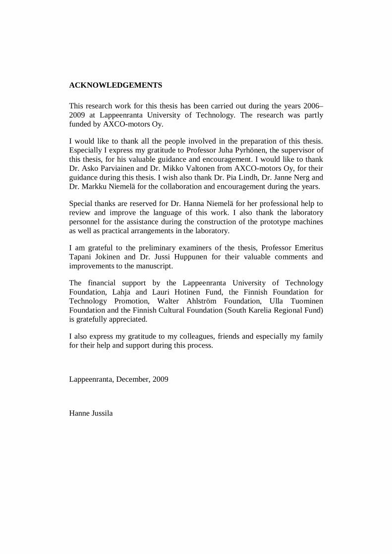
ABBREVIATIONS AND SYMBOLS
Roman letters
A, linear current density [A/m]Awh, linear current density of the working harmonic [A/m]B, magnetic flux density [Vs/m2], [T]Bn, normal component of magnetic flux density [T]Bn,wh, normal component of magnetic flux density of the working
harmonic [T]BPM, magnetic flux density [T]Br, remanent flux density [T]b, width [m]b4, stator slot width [m]b1, slot opening width [m]bPM, permanent magnet width [m]bPM,segment, permanent magnet segment width [m]D, diameter [m]Dr, outer diameter of the rotor [m]Di, inner diameter of the stator [m]Di, axial, inner diameter of the axial flux machine [m]Do, outer diameter of the stator [m]Do, axial, outer diameter of the axial flux machine [m]D , air gap diameter [m]d, thickness [m]EPM, electromotive force (emf) [V], RMSe, electromotive force (emf) [V]F, force [N]Ftan, tangential force [N]f, frequency [Hz]g, coefficient, constantH, magnetic field strength [A/m]h, height [m]hPM, height of magnet [m]hys, height of stator yoke [m]Is, current [A], RMSis, current [A], instantaneous value i(t)iu, slot current [A], instantaneous value i(t)J, current density [A/m2], magnetic polarizationJPM, current density in permanent magnet [A/m2]Kn, coefficientk, constant

kad, additional loss coefficientkC, Carter factorkd, distribution factorke, keh, kexe, kh, constantkFeys, kFets, constantkp, pitch factorksq, skewing factorkw, winding factorkw1, winding factor for the fundamental wavekw,wh, winding factor for the working harmonick , coefficientLd, direct-axis inductance [H]Lmd, magnetizing inductance of an m-phase synchronous machine, in
d-axis [H]Lmq, magnetizing inductance of an m-phase synchronous machine, in
q-axis [H]Lq, quadrature-axis inductance [H]L , stator leakage inductance [H]Lu, slot leakage inductance [H]Lw, end winding leakage inductance [H]Lz, tooth tip leakage inductance [H]L , air gap leakage inductance [H]l, length [m], effective core length [m]
lew, average conductor length of winding overhang [m]lFe, stator stack core length [m]lmf, main flux path length [m]lr, rotor core length [m]lw, length of coil ends [m]m, number of phases, mass [kg]NPM, number of permanent magnet segmentsNs, number of turns in series per stator windingn, exponentns, rotation speed (rotation frequency) [1/s]P, power, losses [W]PCu, copper losses [W]PFe,ec, iron Joule losses [W]Phy, hysteresis loss [W]Pin, input power [W]Pout, output power [W]Pad, additional loss [W]PPM, ec, permanent magnet Joule loss [W]P , mechanical loss [W]

p, number of pole pairs, ordinalQ, number of slotsq, number of slots per pole and phase,Rs, resistance [Ω]r, radius [m]rPM, radius of permanent magnet [m]rr, outer radius of the rotor [m]ri, inner radius of the stator [m]ri, axial, inner radius of the axial flux machine [m]ro, outer radius of the stator [m]ro, axial, outer radius of the axial flux machine [m]r , air gap radius [m]S, cross-sectional area [m2]ssq, skewing pitchT, torque [Nm], periodTN, rated torque [Nm]Tmax, maximum pull-out torque, peak torque [Nm]t, time [s]U, voltage [V], RMSUs, voltage [V], RMSV, volume [m3]VPM, volume of permanent magnet [m3]v, speed, velocity [m/s]vr, rotor speed, velocity [m/s]W, coil span (width), [m]w, width [m]x, coordinate, lengthy, coordinate, length, winding stepyQ, full step
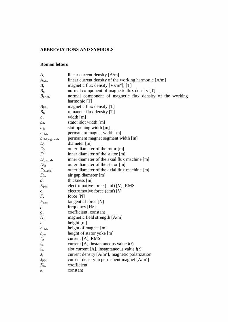
Greek letters
α, angle [rad], [°], coefficient, temperature coefficientα PM, relative permanent magnet widthβ, angle [rad], [°]γn, angle [rad], [°]δ, air gap (length) [m], skin depth [m], load angle [rad], [°]
PMδ , magnetic air gap (influence of physical air gap and permanentmagnet taken into account) [m]
PMδ ′ , equivalent air gap (influence of physical air gap and permanentmagnet and Carter factor taken into account) [m]
δef, effective air gap (in addition to previous, influence of iron takeninto account) [m]
η, efficiency, constantθ, angle [rad], [°], factor for reduction of slot opening
λ, permeance factor, inductance factor, relative permeance factorλlew, λW, λw, end winding leakage factorλu, slot leakage factorλz, tooth tip leakage factorµ, permeability [Vs/Am, H/m]µr, relative permeabilityµr, PM, relative permeability of PMµ0, permeability of vacuum, 4·π·10-7 [Vs/Am, H/m]ν, ordinal of harmonicρ, resistivity [Ωm], density [kg/m3]ρFe, iron resistivity [Ωm]ρPM, permanent magnet resistivity [Ωm]σ, specific conductivity [S/m], leakage factorσPM, permanent magnet conductivityσtan, tangential stress [Pa]σFe, iron conductivity [S/m]σ , air gap leakage factorτp, pole pitch [m]τu, slot pitch [m]Φ, magnetic flux [Vs, Wb]ϕ, phase shift angle [rad], [°]
, magnetic flux linkage [Vs]Ω, mechanical angular speed [rad/s]ω, electric angular velocity [rad/s], angular frequency [rad/s]ωs, stator electric angular velocity [rad/s], stator angular frequency
[rad/s]
Subscripts
ar, mean, arithmetic meanaxial, parameter of the axial flux machineCu, copperFe, irongeom, mean, geometric meani, innero, outer
PM, permanent magnetr, rotors, statort, toothu, sloty, yokewh, working harmonic
Superscripts
^, peak/maximum value, amplitude', imaginary, apparent, referred, virtual
,σ bar above the symbol denotes average value
Acronyms
AC, alternating currentAFPM, axial flux permanent magnetBH, energy productBHmax, maximum energy productDC, direct currentDTC, direct torque controlEC, eddy currentemf, electromagnetic forceFEA, Finite Element AnalysisNdFeB , neodymium-iron-boronPM, permanent magnetPMSM, permanent magnet synchronous motor (or machine)p.u., per unitRMS, root mean square


15
1 INTRODUCTION
The progress in the field of permanent magnet material technology has resultedin very powerful permanent magnet materials at a relatively competitive price,and as a result of that, the era of large industrial permanent magnet machineshas started. For example, with neodymium-iron-boron (NdFeB) magnets, whichhave been commercially available since the mid 1980s, a maximum energyproduct (BHmax) of 400 kJ/m3 and a remanent flux density Br of 1.4 T can beachieved with a proper manufacturing process (Neorem 2009, InternationalMagnetics Association 2000). Nowadays, NdFeB magnets are available withshapes, sizes and grades of great variety.
Permanent magnet synchronous machines (PMSM) provide significantadvantages in terms of electrical efficiency compared with the traditionalelectrically excited synchronous machines. This is because the Joule losses ofthe field winding are eliminated by applying permanent magnets (PM) insteadof rotor windings. Because permanent magnets are part of the magnetic circuitof the machine, they significantly affect the total reluctance of the machine. Therelative permeability µr of modern PM materials such as NdFeB is about equalto 1.05, leading to the fact that the equivalent air gap length in rotor surfacemagnet PMSMs in the direct-axis direction is considerable, thus resulting insmall magnetizing inductance values, which is beneficial from the viewpoint ofhigh pull-out torque production. The main drawback of the application ofpermanent magnets is that the rotor magnetization cannot be controlled. Forexample, in order to gain field weakening, demagnetizing stator current isrequired, which is not very efficient. However, the progress in the PM machinedesign, power electronics and particularly in different motor control schemessuch as direct torque control (DTC) and sensorless vector control have resultedin a wide variety of industrial applications of electric drive systems wherePMSMs are applied.
PM motor technology is also penetrating into the field of network-drivenmachines (Polinder et al. 2006, El-Rafaie and Jahns 2007, Kinnunen 2007), inwhich a mechanical gearbox is eliminated and thus the efficiency, performanceand reliability of the drive system are enhanced. Of course, the same benefitshold true also for frequency-converter-driven speed-controlled applications. Aspecially designed direct drive PMSM may, in some applications, efficientlycompete with a traditional induction motor drive with a gear both with respectto the space needed and the overall efficiency of the drive.
Compared with induction motors, clear benefits in terms of energy efficiency,power factor and speed control accuracy without speed encoders can beobtained by utilizing permanent magnet motor technology. Efficiency and

16
power factor benefits are, however, achieved best in drives applying multiplepole motors. For example, the designer of PMSMs has more freedom inselecting machine layout features and parameters such as the number of polepairs, which in turn provides benefits in integrated machine systems.Furthermore, the power factor of an induction machine decreases rapidly as thenumber of poles is increased, which can be indirectly seen in the followingequation describing the direct axis magnetizing inductance of an integral slotwinding machine (Pyrhönen, Jokinen, Hrabovcová 2008)
( ) ,'2 2
sw1ef
p0md Nkl
pL
δτ
= (1.1)
where m is the number of the phase, µ0 is the permeability of air, τp is the polepitch, is the effective length of the stator core, p the number of pole pairs, efthe effective air gap length taking also the effect of iron into account, kw1 thewinding factor for the fundamental wave and Ns number of turns in series perstator winding. Distributed fractional slot windings are outside the scope of thiswork, and hence, the discussion and references on distributed windings concernintegral slot windings only.
The magnetizing current of an induction motor is about inversely proportionalto the magnetizing inductance. As the pole pitch τp is inversely proportional tothe number of pole pairs p, the magnetizing inductance is thereby inverselyproportional to the square of the number of pole pairs ,/1 2
md pL ≅ and hence,the induction machine power factor rapidly decreases as the number of polesincreases.
An interesting field where PMSMs are applied is axial flux machines, which areoften called disc-type machines because of their pancake shape. Axial fluxpermanent magnet (AFPM) machines are, because of their short axial length, anattractive alternative to traditional radial flux PMSMs in electric vehicles,pumps, fans, valve control, centrifuges, machine tools, robots, industrialequipment and in small- to medium-scale power generators (Gieras et al. 2008).
Integrating an electric motor with a pump, a fan or a compressor or using anelectric motor integrated into the propulsion of an electric vehicle, a windmill, alift or the like seem to be future trends in the applications of electrical machinesto different drives (Reichert 2004). Axial flux machines are, in principle, easilyintegrated into the above-mentioned applications. Also the high efficiency ofpermanent magnet machines in different applications makes the applicationattractive.
17
In pump and fan applications, an axial flux permanent magnet machine is a veryinteresting machine type because of its high power factor and high efficiencycompared with the axial flux induction motor introduced by Valtonen (2007). Insome cases it seems to be easier to integrate such a motor type into a workingmachine construction. Valtonen used an induction rotor where a mechanicallystrong aluminium winding also acts as the rotor mechanical core. The magneticflux carriers inserted in the strong winding are made of solid steel that fastdeteriorates the power factor of the machine despite its high efficiency. Thepower factor in axial flux induction machines having solid steel active partsvaries usually between 0.6 and 0.8 while permanent magnet machines providepower factors in the range of 0.90–0.95. A high power factor is beneficial as itresults in a lowest possible stator current. Consequently, a low currentcapability frequency converter may be selected. The highest power factors closeto unity, however, consume extra permanent magnet material, and often the bestpower factor is in the range of 0.9–0.95 in PMSM drives.
The manufacturing process of AFPM machines can be simplified considerablycompared with traditional radial flux machines: The stator may bemanufactured from narrow electrical steel bands, and hence, the waste of thelamination material is kept to minimum. Only the punching waste from thestator slots is recycled. However, the manufacturing process of an axial fluxstator core is technically demanding and calls for high accuracy; nevertheless,the process can be automated. In radial flux machines with both the stator andthe rotor made of laminations, the amount of wasted lamination material isrelatively small but substantially larger than in an axial flux machine, asbetween the stator roundels there always remains some unused material. Thebest benefit, however, may be the easiness of the winding manufacturingprocess, which can be performed in a plane compared with working inside acylinder, which is the case in inner rotor radial flux machines. With the two-stator-single-rotor construction, where the magnetic flux travels through thepermanent magnets from one stator to another the rotor of the machine can bekept totally ironless. This makes the manufacturing of the permanent magnetrotor very simple and inexpensive. The adverse effect is, of course, that twostators are needed.
Concentrated windings together with the axial flux technology provide a furthermanufacturing benefit. When open stator slots and concentrated windings areused, prefabricated coils can just be inserted around the stator teeth, and thewinding process becomes very low-cost compared for example with double-layer short-pitched normal integral slot windings. Furthermore, the spaceneeded by the end-windings is minimized. Hence, concentrated winding axialflux permanent magnet motors are very cost effective from the manufacturingpoint of view. The shortening of the end windings and a high power factor
18
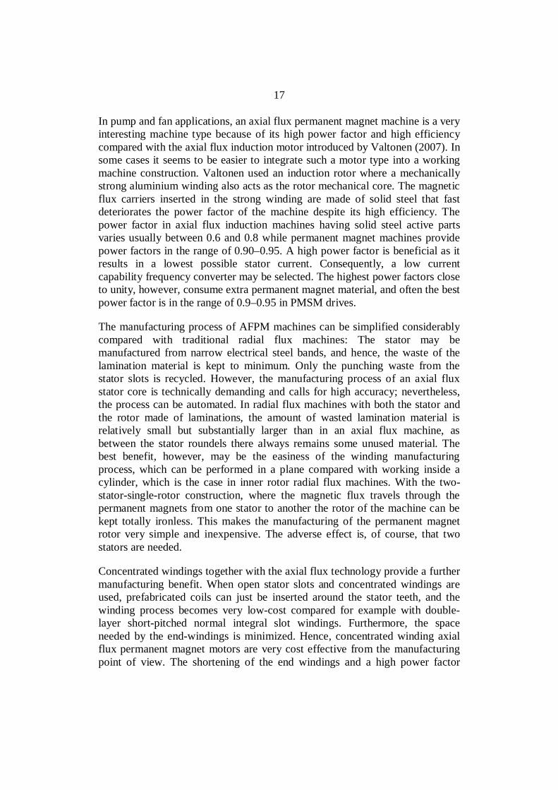
make it possible to minimize the stator Joule losses. The end-windings of anaxial flux concentrated winding machine and a traditional integral slot windingmachine are presented as an example in Fig. 1.1. In this work, concentratedwinding refers to a fractional slot winding with concentrated coils, e.g. thenumber of slots per pole and phase q ≤ 0.5. Even when using open slots, theconcentrated winding machine may provide very low cogging torque values,and hence, the torque quality of the motor can be good. Cogging torque is thetorque resulting from the interaction between the permanent magnets of therotor and the stator slots. Cogging occurs even when there is no current in thestator (Baracat et al. 2001, Hanselmann 2003, Gieras et al. 2006).
a) b)
Fig. 1.1. a) End winding of a concentrated winding machine and b) an integral slot windingmachine
The cogging of the motor as a function of the relative magnet width, that is, themagnet width divided by the pole pitch, was analyzed in (Salminen 2004,2006). We may conclude that for a certain number of slots per pole and phase q,the amount of cogging torque decreases as the number of slots increases. Theminimum cogging values seem to be found when q is close to 0.33. On thecontrary, the largest cogging torque may be expected when q equals to 0.25 or0.5 (Salminen 2004, Salminen et al. 2006).
When the motor is running, there occur also additional oscillatory torquecomponents because of the interaction of the magnets with the stator spaceharmonics and with the magnetic flux waves created by the current harmonics.These oscillatory components are generally referred to as torque ripple (Crosand Viarouge 2002, Magnussen and Sadarangani 2003, Ishak et al. 2004,

19
Salminen et al. 2005, Gieras 2006). The lowest peak-to-peak torque ripplevalues were obtained for machines with q close to 0.33. The torque ripple tendsto have more than one local minima. For example, local minima can be foundfor two or three different permanent magnet widths, depending on the numberof slots per pole and phase. Thereby it may be concluded that the minimumcogging torque and the minimum torque ripple are found when q is close to thevalue of 0.33 (Salminen 2004, Salminen et al. 2006).
Many examples of PMSMs with concentrated windings can be found in theliterature, most of these being radial flux machines: a 20 kW 2000 min-1 for ahybrid electric propulsion system (Magnussen and Sadarangani 2003,Magnussen et al. 2003, Magnussen et al. 2004), a 5 kW 50 min-1 machine for anindustrial application (Libert and Soulard 2004), a 45 kW 1000 min-1 machine(Deak et al. 2006, 2008) and a 18.5 kW 1700 min-1 machine for automotiveapplications (Wang et al. 2005). Salminen (2004) focused on 45 kW 400 min-1
concentrated winding machines, for example paper mill applications.
The latest development and applications are found in 0.26 kW–10 kW radialflux permanent magnet machines with concentrated windings: a 6 kW 600 min-1
machine for traction purpose (El-Refaie et al. 2006, El-Refaie and Jahns 2006),a 10 kW 370–440 min-1 machine for an in-wheel drive application (Rix et al.2007), a 5–10 kW 200-240 min-1 machine for wind turbines (Cistelecan et al.2007) and a 0.26 kW 250 min-1 for a bicycle application (Wrobel and Mellor2005).
Some examples of concentrated winding axial flux machines can also be foundin the literature: a 1.6 kW 250 min-1 axial flux permanent magnet machine,designed to operate as a generator in a small-scale wind power application(Parviainen et al. 2005), 1 kW and 200 min-1 laboratory prototype concentratedwinding AFPM machines with air-cored stators (Kamper et al. 2007, 2008) anda nine-phase axial flux PM generator with concentrated windings for a directdrive turbine (Vizireanu et al. 2006).
In the above-mentioned work, a comparison of the PMSMs equipped with openstator slots and semi-closed stator slots with different pole pair – slotcombinations was carried out in terms of pull-out torque production capabilityand electrical efficiency. Using semi-closed slots, the stator winding losses andthe eddy-current losses in the permanent magnets were lower than with similarmotors having open slots (Parviainen 2005, Salminen 2004, Lindh et al.“Concentrated Wound PM Motors with Semiclosed Slots and with Open Slots”IEEE Energy Conversion (forthcoming)). The flux travelling from thepermanent magnet rotor to the stator is higher with semi-closed slots, and thusin open slot structures with the same main dimensions, a higher number of

20
winding turns are needed to induce an appropriate voltage. The semi-closed slotstructures had slightly higher stator iron losses than the corresponding open slotstructures because of the higher amount of flux in the stator teeth and yoke. Thepermanent magnet flux density pulsation is, of course, larger in open slotconstructions than in semi-closed slot structures. The open slot structures gaveslightly higher pull-out torques (because of low inductances), but theefficiencies of open slot structures remained somewhat lower than those ofcorresponding semi-closed structures, mainly because of high stator windinglosses. Figure 1.2 clearly indicates the effect of wide teeth tips on the flux of themachine.
2.0 T
0.8 T0.9 T
1.7 T
0.4 T0.7 T
(a) (b)
Fig. 1.2. Effect of wide and narrow tooth tips on the flux of otherwise similar machines. Theflux paths and flux densities of a 24-slot 16-pole machine a) with semi-closed slots and b) withopen slots are shown (Lindh et al. “Concentrated Wound PM Motors with Semiclosed Slots andwith Open Slots.”IEEE Energy Conversion (forthcoming).
The only significant problem related to the design of open slot concentratedwinding machines is that there can be large eddy current losses produced by theflux variations in the permanent magnets (Polinder and Hoeijmakers 1999,Toda et al. 2004). This is a problem especially when using sintered magnets. If,however, sintered NdFeB magnets are divided into several insulated sections(Polinder and Hoeijmakers 1999, Toda et al. 2004, Zhu et al. 2004, Deak et al.2006, Ede et al. 2007, Deak et al. 2008), acceptable loss levels may be found,but the magnet configuration must be carefully analyzed to attain an acceptableeddy current loss level in the magnets. Plastic-bonded magnets, with a
21
maximum energy product of 100 kJ/m3 and a remanent flux density Br of 0.78 T(Neorem Magnets, 2009), typically have very low eddy current losses (Kume etal. 2005, El-Rafaie and Jahns 2007, El-Rafaie and Jahns 2008), but othermagnetic properties of such magnet materials available on the market are notsatisfactory at the moment.
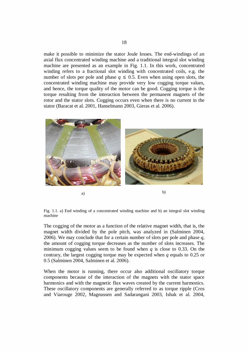
If eddy current losses in permanent magnets can be minimized thereby keepingthe magnets at as low temperature as possible during machine operation, theopen slot concentrated winding design can be very competitive and provide anew energy saving choice for industrial and many other purposes. The effect oftemperature on the demagnetization characteristics of a typical NdFeB magnetmade by NEOREM 495a / NEOREM 595a is shown in Fig. 1.3. When theoperating temperature of the magnet is increased above a critical temperatureand the demagnetizing field strength is large enough, it will result in irreversibledemagnetization of the magnet. Such a situation may take place for instanceduring a sudden short circuit of the machine stator terminal. As industrialmachines must tolerate such a situation, selection of the magnet material andmotor design have to be carried out carefully taking this issue into account.NEOREM 495a tolerates a negative flux density at 100 degrees Celsius andabout zero flux density at 150 degrees Celsius. Axial flux single stator designshave a large rotor yoke surface against cooling air, which usually results in aconsiderably cooler rotor than in a corresponding radial flux machine with aninner rotor. This makes the selection of the magnet material in a single-sidedaxial flux machine somewhat easier.
Fig. 1.3. Demagnetization characteristics of NEOREM 495a/NEOREM 595a NdFeB permanentmagnet material at different temperatures (Neorem Magnets, 2009).
22
1.1 Harmonics of concentrated windings
In integral slot winding machines, the energy conversion process is related tothe fundamental component of the flux density, which is produced by theinteraction of the stator and rotor fundamental current linkages (Pyrhönen,Jokinen, Hrabovcová 2008). The concentrated winding machines, however,operate at some of the stator current linkage harmonics (Jokinen 1973, Atallah2000). For instance in this case, we study the behaviour of a 12-slot 10-polethree-phase machine with the number of slots per pole and phase q = 0.4. Sucha machine operates at the fifth harmonic, not the fundamental component of theflux density. The fundamental has a low winding factor and the flux related tothe fundamental is, hence, low. In the theory of concentrated machines thereseem to be two alternative approaches: Either the machine is really consideredto operate at the fifth harmonic when all the harmonics of the machine are 1,−5, +7, −11, +13 and so on, or the fifth harmonic of the machine is denominatedthe fundamental when the real first harmonic is regarded as a sub-harmonic ofthe order −1/5 (Zhu et al. 1991, Atallah et al. 2000, Ede et al. 2007). All theother harmonics of the machine are then treated accordingly.
As the 12-10-machine happens to produce harmonics of the same order asintegral slot winding machines, it is easy to apply the traditional way of treatingthe harmonics similarly as in an integral slot winding machine. The 12-10machine is regarded as a base machine having a base winding embedded in 12stator slots and a rotor consisting of 10 permanent magnet poles with p = 5.When in a 12-stator slot concentrated winding three-phase machine p of thebase winding is odd (in practice p = 5 or p = 7), the harmonics ν of a three-phase machine (m = 3) are according to the equation
km21±=ν , (1.2)
where k ∈ N0. Eq. (1.2) produces the harmonics [ ]...13,11,7,5,1 +−+−=ν for thewinding current linkage ordinals. In this case (12-slot 10-pole), the machineoperates at the fifth harmonic 5−=ν . As a result, the fundamental 1+=νrotates at a speed five times the speed of the fifth harmonic and in an oppositedirection thus resulting in a rotor surface speed six times the rated electricalspeed of the rotor. As the fundamental has a considerable amplitude, it iscapable of inducing large rotor losses if the rotor has some conductivity. It is, ofcourse, possible to build machines carrying multiple 12-10 base machines. Forexample 24-20 and 36-30 machines are possible, the former consisting of twobase machines and the latter of three base machines. Each of these works,however, with the fifth harmonic of the base machine.
23
According to a more general approach the ordinals ν of an m-phaseconcentrated winding base machine can be calculated by equation (Ede et al.2002, Amara et al. 2005, Nakano et al. 2006)
km±= 1ν , (1.3)
where k ∈ N0. Equation (1.3) produces the harmonics [ ]...7,5,4,2,1 +−+−=ν forthe winding current linkage ordinals of the three-phase machine. The machinealways operates at the pth harmonic of the base machine. For example in 12-10or 12-14 machines, however, the even harmonics are cancelled because both thestator and rotor of the base machine can be symmetrically divided into two 180-degree sectors.
The winding factors will be observed next. The working harmonic windingfactor kwh of the machine has to be high and other harmonics should have lowwinding factors. The winding factor can be defined by a voltage vector graph(Pyrhönen, Jokinen, Hrabovcova 2008), or in simple cases, it can be solvedfrom analytical equations. In general, the winding factor can be solved from
νννν sqdpw kkkk ⋅⋅= , (1.4)
where kpν is the pitch factor, kdν is the distribution factor and ksqν is the skewingfactor for the harmonic ν. In concentrated windings, obviously, the distributionfactor kdν cannot be simply defined for fractional slot windings withconcentrated coils. The pitch factor kpν, however, is defined in general as(Pyrhönen, Jokinen, Hrabovcova 2008)
=
=
2sin
2sin
Qpp y
yWk ντ
ν (1.5)
where W is the coil width, y the winding step and yQ the full step. For aconcentrated base winding y = 1 and 2yQ = Q. Hence, in such a case
=
Qk sin ν . (1.6)
This pitch factor is enough for single layer 12-10-machines and gives thewinding factor for the working harmonic kwh = 0.966. In double layer 12-10machines, also the distribution factor is needed.

24
The skewing factor can be solved from the equation (Pyrhönen, JokinenHrabovcova 2008)
2
2sin
p
sq
p
sq
sq
τν
τν
s
s
k
= , (1.7)
where ssq/τp is the skewing pitch ratio to the pole pitch. Skewing is used tominimize torque ripple.
As the definition of the distribution factor is not clear, we use the voltage phasorgraph in solving the winding factors for the 12-10 two layer machine, Fig.1.4.As we now assume that – despite the five-pole-pair rotor – the winding producesa two pole fundamental wave, the machine has to be originally treated as a p = 1machine. The angle between the voltage phasors in the adjacent slots is given byexpression
Qp°
=360
uνα . (1.8)
For the fundamental ν = 1 (p = 1) the slot angle is
°=⋅°⋅
= 3012
13601uα (1.9)

25
12
3
4
5
67
8
9
10
11
12
+U
-U+U-U +W
-W-W
+W -V
+V+V
-V-U-U
+W+W
-V-V
+V
+V -W
-W+U
+U
a)
11-2
-12
11211
10
9
87 6
5
4
3
2
1
-2
1
-12
1
-2
1
-12o
u 30=α
1=ν 5−=ν 7=ν
11-2
-12
11−=ν
11-2
-12
13=νo
u1 30=αo
11-u 330−=α ou13 30=α o
5-u 150−=α ou7 210=α
b)
Fig. 1.4. a) Winding arrangement of a 12-10-machine. b) Voltage phasor graph for thefundamental and sum phasors for different harmonics of the 12-10-two-layer winding for phaseU located in slots 12–1 and 1–2.

26
The winding factors of the 12-10-machine are now found with the sum phasorgraps kw1 = (1 + 1 – cos30° – cos30°)/4 = 0.067, kw-5 = 0.933, kw7 = 0.933, kw-11= 0.069, kw13 = 0.067, kw-17 = 0.933 etc. In this machine kw-5 = kwh, which is theworking harmonic of the machine.
As the pitch factors are in this case kp1 = 0.259, kp-5 = – 0.966, kp7 = 0.966, kw-11= 0.259, kw13 = 0.067, kw-17 = 0.933 and so on, the distribution factors shouldhave the same values to produce the winding factor of the double-layer 12/10machine windings.
Both forward- and backward-rotating harmonic current linkages that do notrotate in synchronism with the rotor may induce significant rotor eddy currentlosses. This is especially important in concentrated winding machines. To avoidthe negative effects caused by the harmonics, the rotor should, in principle,have no conductivity at all – the rotor materials should be perfect insulators.The present-day sintered permanent magnets are far from insulators. NdFeBmagnets have a resistivity varying between 100–200×10−8 m (Neorem 2009).Such resistivity values, being only from four to eight times the resistivity ofnormal construction steel, let large eddy currents run in bulky magnets, andhence, significant eddy current losses may take place in the magnets if nospecial efforts are made to prohibit the eddy currents from running.
The stator current linkage harmonics and the spatial harmonics caused by thestator slotting (permeance variations) cause variations of the magnetic field inthe magnets. The permeance-harmonics-caused components of the rotor eddy-current losses depend on the width of the slot openings (Toda et al. 2004).
As in all normal three-phase motors, the multiples of the third harmonic field donot induce any back electromotive force (emf) harmonics in the line-to-linevoltages of a three-phase machine, and hence, the third harmonic may bepresent in the phase voltage of the machine without causing adverse effects.
1.2 Scope of the work and outline of the thesis
This work done in Lappeenranta University of Technology is a follow-up to theresearch series concentrating on permanent magnet machines. Tanja Heikkilä(2002) studied multiple-pole buried V-magnets in radial flux machines andnoticed that the torque density calculated with the machine outer dimensionscan be considerably increased compared with a four-pole induction machine inthe same frame. Panu Kurronen (2003) investigated torque quality andminimization of torque ripple in axial flux machines. Pia Salminen’s work(2004) provided new information about the behaviour and characteristics offractional slot radial flux machines. Asko Parviainen (2005) made a similar

27
study on different axial flux machines concentrating also on the thermal designof axial flux single rotor double stator machine. Janne Kinnunen (2007)examined damping properties and realization of damper windings in axial fluxmachines.
This work includes a number of main tasks related to the application ofpermanent magnets concentrated winding open slot machines. Suitableanalytical methods are required for the first design calculations for a newmachine. Concentrated winding machines differ from normal integral slotwinding machines in such a way that adapted calculation methods are needed.To this end, a simple analytical model for calculating the concentrated windingaxial flux machines is provided in this work. Determination of the magnetizingand leakage inductances for a concentrated winding machine differs slightlyfrom traditional calculation methods. Torque production capability ofconcentrated winding machines with different pole pair numbers and comparedwith integral slot winding machines is studied in detail to show the potential ofthe machine type for different applications. The magnetic length of rotorsurface magnet machines is studied and it is shown that the traditional methodshave to be modified also in this respect. The results of this study are valid for allrotor surface permanent magnet machines without cooling ducts. An importanttopic in this study has been evaluating and minimizing the rotor permanentmagnet Joule losses using segmented magnets in the calculations andexperiments. On the other hand, a concentrated winding produces a largeamount of harmonics – even sub-harmonics depending on the determination ofthe harmonic system. Such a winding is, in practice, suitable only for thepermanent magnet synchronous machines because the rotor conductivity shouldbe as low as possible – preferably zero (Magnussen and Lendenmann 2007,Pyrhönen, Jokinen, Hrabovcova 2008).
In this work, a prototype AFPM machine with concentrated windings, twostators and a single rotor is designed and measured. Four different prototypeversions were used in the measurements: 1) a rotor with no magnets, 2) a rotorwith bulky magnets, 3) a rotor with radially segmented magnets and 4) a rotorwith tangentially segmented magnets (Figure 1.5). The two-stator-one-rotordesign balances, in principle, the axial magnetic forces acting between thestators and the rotor.

28
Fig. 1.5. Magnet versions, slicing directions.
Chapter 2 The chapter introduces the equations to analytically calculate thecorrect mean radius and magnetic length of the axial fluxconcentrated winding machine. This is done to solve theinherently 3D axial flux machine problem as a two-dimensionalflux problem. Air gap flux density, back-emf, magnetizing andleakage inductances, especially air gap leakage inductance, androtor Joule losses are analyzed. 2D and 3D Finite ElementAnalysis (FEA) results are compared with each other and theiranalytical counterparts are verified.
Chapter 3 The torque production capability of a concentrated windingmachine with different slot-pole combinations is analyzed. Acomparison between the pull-out torques of concentratedwinding and integral slot winding machines is made and reportedin detail.

29
Chapter 4 The results determined by a 2D analytical approximation arecompared with the 2D and 3D Finite Element Analysis (FEA)and measurements on different rotor topologies.
Chapter 5 The final chapter summarizes the contributions of the work.
1.3 Scientific contributions of the work
The thesis has the following objectives:
1. Introduction of analytic equations and methods to design a 12-slot 10-pole axial-flux machine (or its multiple) with rotor-surface-mountedmagnets.
2. Determination of the correct magnetic length of a PMSM with rotorsurface magnets.
3. Determination of the stator leakage inductance, in particular the air gapleakage inductance in concentrated winding machines.
4. Comparison of the torque production capabilities of concentratedwinding and integral slot winding machines.
5. Evaluation of the permanent magnet Joule losses in an axial flux PMSMwith open slots.
6. Introduction of a new practical permanent magnet motor type forindustrial use. The special features of the machine are due to thepossibility of using concentrated winding and open slot windingconstructions of PMSM at the normal speed range of industrial motors,for instance up to 3000 min-1, without excessive rotor losses.
1.4 Most relevant scientific publications
The rated rotational speeds for the analyzed motors vary from 400 min-1 to 3000min-1. Concentrated winding radial and axial flux machines are used incalculations. Different slot-pole combinations are analyzed, the emphasis beingon 12-slot 10-pole machines, which are investigated in detail. The most relevantpublications are listed below.
Various low-speed high-torque permanent magnet synchronous motors withconcentrated windings and with different slot and pole combinations werecalculated analytically and by applying the finite element method (Flux2D™ byCedrat) in publications P1–P6. All the calculated motors were radial fluxmachines with the same frame size of 225, air gap diameter, air gap length andthe same amount of permanent magnet material. A speed of 400 min-1 and anoutput power of 45 kW were used. Comparisons of the torque ripple and thecogging torque, losses and pull-out torques were carried out. In publications

30
P4–P5, also the motor losses and torque capabilities in either open or semi-closed stator slots were compared. The differences of rotor surface magnets andembedded magnets were analyzed in publication P6. Publications P1 and P3have been written by the author of this doctoral dissertation. In publication P1,Hanne Jussila essentially contributed to determination of the iron losses andstator inductances. In publication P3, Hanne Jussila played a key role inpresenting the requirements that are usually set for desirable machineconstructions and determination of the stator inductances of the machines.Publication P2 has been written by Pia Lindh (formerly Salminen). In thispublication, Hanne Jussila contributed to the determination of the coggingtorque values by analytical cogging torque equations. Publication P4 has beenwritten by Pia Lindh. In this publication, Hanne Jussila contributed in particularto the analysis of Joule losses of permanent magnets. The publication P5 and P6has also been written by Pia Lindh. In these publications, Hanne Jussilaessentially contributed to determination of the losses.
P1 Jussila, H., Salminen, P., Niemelä, M. and Pyrhönen, J. 2006.“Comparing Different Slot-Pole Combinations of a Concentrated-Winding Fractional-Slot Permanent-Magnet Machine.” InProceedings of the Nordic Workshop on Power and IndustrialElectronics, NORPIE 2006. Lund, Sweden. CD.
P2 Salminen, P., Jussila, H., Niemelä, M. and Pyrhönen, J. 2006.“Torque Ripple and Cogging Torque of Surface Mounted PMMachines with Concentrated Windings.” In Proceedings of theXVII International Conference on Electrical Machines, ICEM2006. Chania, Crete Island, Greece. CD.
P3 Jussila, H., Salminen, P., Niemelä, M. and Pyrhönen, J. 2007.“Guidelines for Designing Concentrated Winding Fractional SlotPermanent Magnet Machines.” International Conference onPower Engineering, Energy and Electrical Drives, POWERENG2007. Setúbal, Portugal. CD.
P4 Salminen, P., Jussila, H., Niemelä, M. and Pyrhönen, J. 2008.“Concentrated Wound Permanent Magnet Motors with DifferentPole Pair Numbers.” IOS Press – Studies in AppliedElectromagnetics and Mechanics, Vol. 30, 2008, pp. 253–258.
P5 Lindh, P., Pyrhönen, J., Parviainen, A., Jussila, H. andNiemelä, M. “Concentrated Wound PM Motors with SemiclosedSlots and with Open Slots.” IEEE Energy Conversion.Forthcoming.
31
P6 Lindh, P., Jussila, H., Niemelä, M., Parviainen, A. andPyrhönen, J. 2009. “Comparison of Concentrated WindingPermanent Magnet Motors with Embedded Magnets and Surface-Mounted Magnets.” IEEE Transactions on Magnetics. Vol. 45,Issue 5, May 2009, pp. 2085–2089.
Publication P7 addresses concentrated winding permanent magnet motors andtheir ability to produce torque. Further, torque comparisons for integral slotwinding machines were made. The inductances and the maximum availabletorque of a concentrated winding PM machine were examined as the pole pairnumber and the number of slots per pole and phase q were varied withincompatible constraints. The machines under study had a 45 kW output powerand a speed of 400 min-1. The results show that as q increases from 0.25 to 0.5,the pull-out torque of the concentrated winding machine increases, obtainingthe highest values when q equals to 0.5. However, as q increases further andintegral slot windings (q = 1, q = 2) are used, the torque development will behigher when the same rotor main dimensions are maintained. This indicates thatthe selection of a concentrated winding construction must have other relevantreasons than maximizing the rotor torque per volume ratio. Finite elementanalysis (Flux2D/3D™ by Cedrat) and analytical equations were used incalculations. The author of this doctoral dissertation has been the first author inthis publication. Hanne Jussila contributed in particular to determination of thestator inductances and the maximum available torques of the machines.
P7 Jussila, H., Salminen, P., Niemelä, M., Parviainen, A. andPyrhönen, J. 2007. “Torque and Inductances of ConcentratedWound Permanent Magnet Machines.” International Review ofElectrical Engineering (I.R.E.E.). Vol. 2, No. 5, September–October 2007, pp. 704–710.
Publications P8–P10 focus on the iron losses and the eddy-current losses of themagnets in concentrated winding PM machines. Publication P8 deals with losscalculations of low-speed, 400 min-1, 45 kW permanent magnet synchronousmotors with concentrated windings. The eddy-current losses in permanentmagnets of 3000 min-1, 18.5 kW radial flux permanent magnet synchronousmotors with concentrated windings are reported in publication P9. Differentgeometries and materials, such as open and semi-closed slots, different air gaplengths, sintered and plastic-bonded Neo-magnets were evaluated. In addition,the effects of a semi-magnetic slot wedge on the losses were analyzed. Theeddy-current losses in the magnets of a 2500 min-1 / 3000 min-1, 37 kW axialflux permanent magnet synchronous motor with concentrated windings arereported in publication P10. Different magnet materials, such as plastic-bondedNeo-magnets and sintered segmented NdFeB-magnets were evaluated.

32
Analytical Matlab™ and finite-element-method-based (Flux2D/3D™ byCedrat) programs were used in the calculations. The author of this doctoraldissertation has been the first author in all the publications below. Hanne Jussilahas essentially contributed to determination the eddy-current losses inpermanent magnets.
P8 Jussila, H., Salminen, P. and Pyrhönen, J. 2006. “Losses of aPermanent Magnet Synchronous Motor with ConcentratedWindings.” In Proceedings of the 3rd International Conference onPower Electronics, Machines and Drives, PEMD 2006. Dublin,Ireland, pp. 207–211.
P9 Jussila, H., Salminen, P., Pyrhönen J. and Parviainen, A. 2007.“Permanent Magnet Eddy-current losses in concentrated winding12-slot-10-pole machines.” In Proceedings of InternationalSymposium on Electromagnetic Fields in Mechatronics, Electricaland Electronic Engineering, ISEF 2007. Prague, Czech Republic.CD.
P10 Jussila, H., Salminen, P., Parviainen, P., Nerg, J. andPyrhönen, J. 2008. “Concentrated Winding Axial Flux PermanentMagnet Motor with Plastic Bonded Magnets and SinteredSegmented Magnets.” In Proceedings of the XVIII InternationalConference on Electrical Machines, ICEM 2008. Vilamoura,Portugal. CD.
33
2 ANALYTICAL METHODS FOR CALCULATION OF AXIAL FLUXCONCENTRATED WINDING PM MACHINES
This chapter addresses the analytical design method of concentrated windingaxial flux permanent magnet machines. First, the air gap flux density, with aspecial emphasis on slot effects, is analyzed. Secondly, the torque productioncapability of the machine as a part of the synchronous inductance Ld calculationis addressed. The last main object is to analyze some calculation methods forlosses of the concentrated winding multiphase PM machine, with a specialreference to Joule losses of PMs.
Analytical methods are used in everyday basic machine design because they arefast and easily produce the first practical dimensions of the desired machine.Each design type, however, has its special features, and hence, new analyticalmachine design tools are frequently needed. For example, in this case, the targetis to analyze concentrated winding multiphase machines, which call for adifferent approach compared with traditional machine design. Numericalmethods are used together with analytical ones to refine the design.
In the calculations and measurements, a 37 kW, 2400 min-1, 12-slot 10-poleprototype axial flux motor is used as a base reference (Machine 1). Theprototype machine has two stator stacks with one internal, ironless rotor disc,two-layer concentrated windings (two coil sides share each slot vertically) androtor surface magnets. In the two-layer winding, the slots are divided verticallybecause it minimizes the length of the end windings (Salminen 2004). Otherreference machines for calculation are concentrated winding radial fluxmachines with an output power of 45 kW and a speed of 400 min-1 (Machine 2;Salminen 2004). In order to verify the analytical results obtained by thecalculation, 2D and 3D FEA are performed. The finite element analysisprogram used in the computations is a Flux2D/3D version 10.2.4 by Cedrat.Finally, a comparison of the experimental results for a prototype machine ispresented in Chapter 4. The main parameters of the machines are presented inTable 2.1.

34
Table 2.1. Main parameters.
Parameter Machine 1 Machine 2
Machine type axial flux;two stator, one rotor
radial flux;inner rotor
Output power Pout 37 kW 45 kWRotational speed ns 2400 min-1 400 min-1
Stator outer diameter Do 274 mm 364 mmStator inner diameter Di 154 mm 254 mmLength of stator stack lFe 75 mm 270 mmAir gap length 2 mm 1.2 mmNumber of stator slots Q 12 12, 18, 24, 36Number of rotor poles 2p 10 8–84
2.1 Modelling of concentrated winding axial flux machines
Analytical methods are needed for the base calculations of the machines, while2D or 3D FEA are required for more accurate calculation. In particular, inconcentrated winding axial flux machines, the base calculation should beaccurate, because concentrated winding machines do not necessarily have asimilar magnetic symmetry as integral slot winding machines, and therefore, 2Dor 3D finite element modelling and calculation are time consuming. Because ofthe magnetic similarity of every pole, it is possible to model integral slotwinding machines by modelling only one pole or one pole pair. In concentratedwinding machines, the possible symmetrical parts depend on slot and polecombinations as it is shown in Table 2.2.
35
Table 2.2. Some slot-pole combination and symmetries for concentrated winding machines.
Slots/Poles Smallest slots/polescombination
Symmetry parts
9/8 - 112/8 3/2 4
12/10 6/5 212/14 6/7 212/16 3/4 421/20 - 124/16 3/2 824/20 6/5 424/22 12/11 224/26 12/13 224/28 6/7 8
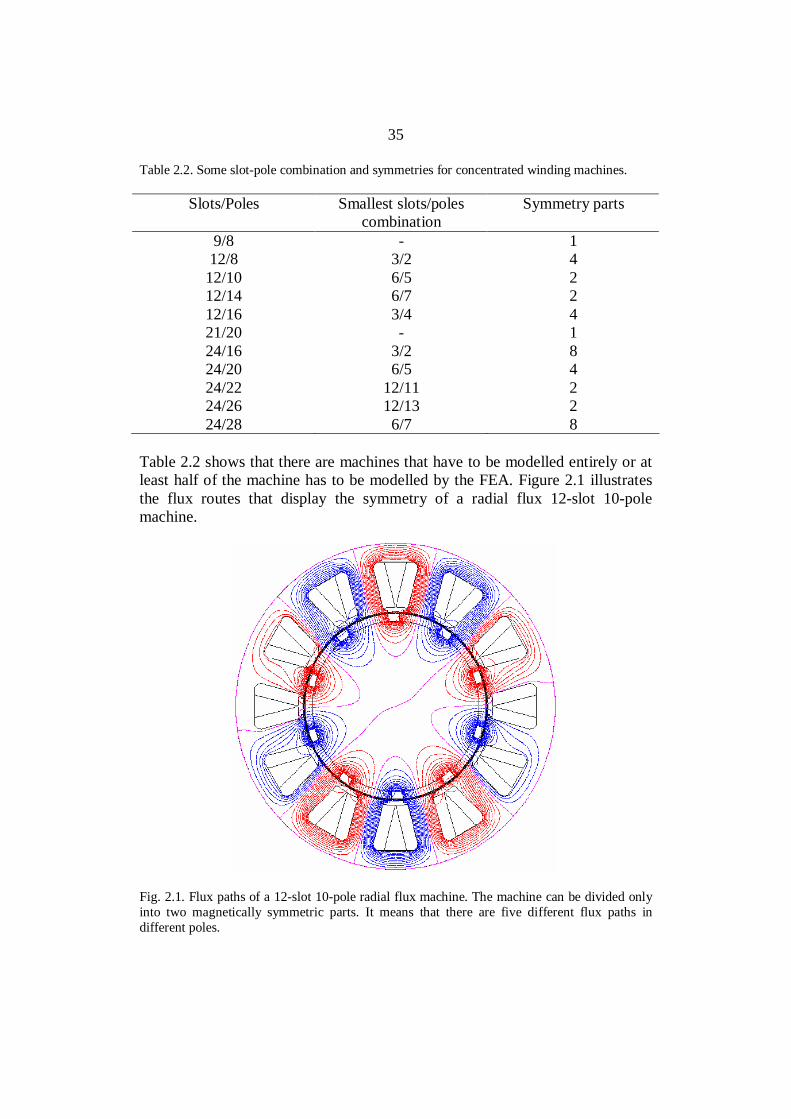
Table 2.2 shows that there are machines that have to be modelled entirely or atleast half of the machine has to be modelled by the FEA. Figure 2.1 illustratesthe flux routes that display the symmetry of a radial flux 12-slot 10-polemachine.
Fig. 2.1. Flux paths of a 12-slot 10-pole radial flux machine. The machine can be divided onlyinto two magnetically symmetric parts. It means that there are five different flux paths indifferent poles.
36
The axial flux machine can be calculated analytically or by 2D FEA tools usingthe geometric mean radius (Valtonen 2007) or the arithmetic mean radius(Gieras et al. 2008) as a design plane. The 2D modelling of the machine can becarried out by introducing a radial cutting plane at the geometric or arithmeticmean radius, which is then developed into a 2D radial flux machine (or linearmachine) model. Either a geometric or arithmetic mean radius is used indifferent references (Valtonen 2007, Gieras et al. 2008). The geometric meanradius rgeom, mean can be calculated as
axiali,axialo,meangeom, rrr = , (2.1)
where ro,axial is the outer radius and ri,axial the inner radius of the axial fluxmachine. In the literature, the arithmetic mean of the air gap radius is also usedas a design plane. For example Gieras et al. (2008) recommend the use ofarithmetic mean rav,mean
2axiali,axialo,
meanav,
rrr
+= (2.2)
in the calculation. If the geometric or arithmetic mean radius is used, themagnet width to pole pitch ratio in an axial flux machine should be constant atdifferent radii and the stator should not be skewed. These methods are suitablefor power, voltage and cogging torque calculation, but they are not accurateenough for iron losses calculation, and at least Quasi-3D is required (Parviainen2005).
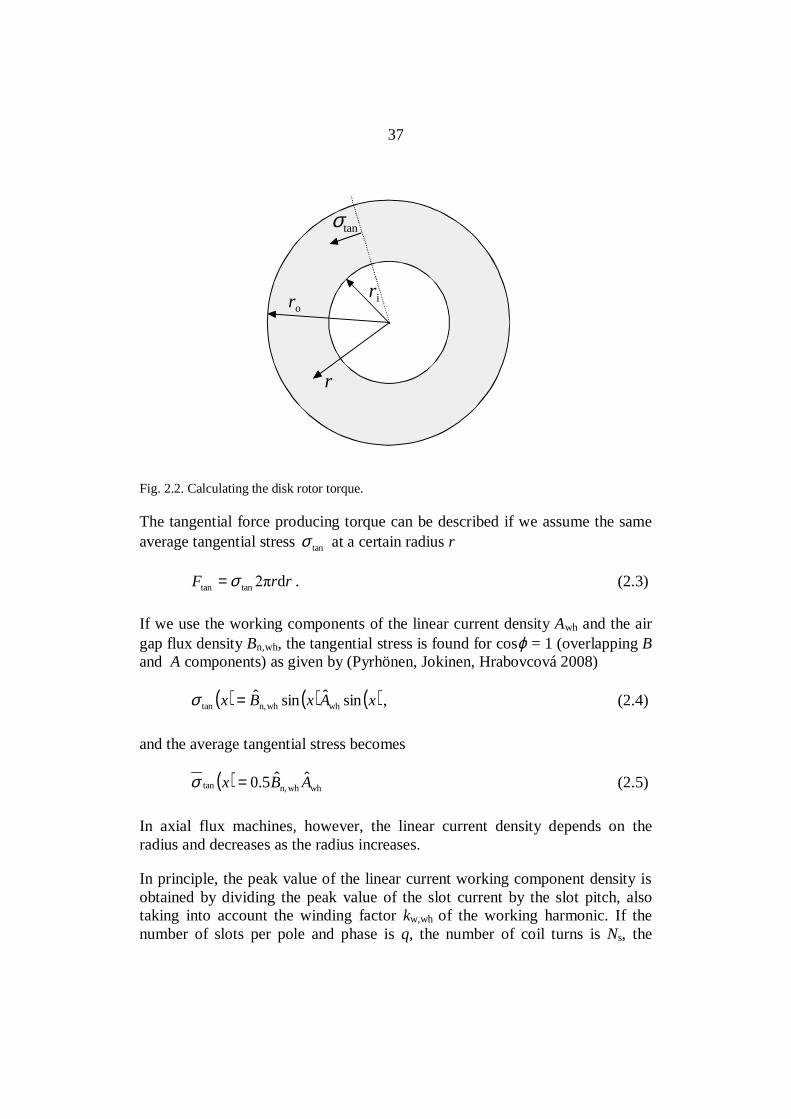
In principle, the rotor torque could be calculated using Fig. 2.2.
37
ri
σtan
ro
r
Fig. 2.2. Calculating the disk rotor torque.
The tangential force producing torque can be described if we assume the sameaverage tangential stress tanσ at a certain radius r
rrF dtantan σ= . (2.3)
If we use the working components of the linear current density Awh and the airgap flux density Bn,wh, the tangential stress is found for cosϕ = 1 (overlapping Band A components) as given by (Pyrhönen, Jokinen, Hrabovcová 2008)
( ) ( ) ( )xAxBx sinˆsinˆwhwhn,tan =σ , (2.4)
and the average tangential stress becomes
( ) whwhn,tan ˆˆ5.0 ABx =σ (2.5)
In axial flux machines, however, the linear current density depends on theradius and decreases as the radius increases.
In principle, the peak value of the linear current working component density isobtained by dividing the peak value of the slot current by the slot pitch, alsotaking into account the winding factor kw,wh of the working harmonic. If thenumber of slots per pole and phase is q, the number of coil turns is Ns, the
38
number of phases is m = 3, and the number of slots is Q, we obtain the effectivepeak current of the slot from the equation
qiNk
i sswh,wu
ˆˆ= , (2.6)
where is is stator current. The slot pitch is
ττ
up=
2Q p/
. (2.7)
Since in a three-phase machine, there is a connection between the number ofslots per pole and phase q and the number of slots Q
Q m pq pq= =2 6 , (2.8)
based on the dimensions of the winding, we obtain for the linear current density
p
sswhw,wh
ˆ3ˆτp
iNkA = . (2.9)
As the pole pitch is
pr
22
p =τ , (2.10)
we see that the linear current density is inversely proportional to the radius r.
riNk
Aˆ3ˆ sswhw,
wh = . (2.11)
If we assume the working component of the flux density to be independent ofthe radius, we can write for the torque producing tangential stress
( ) whwhn,tan ˆˆ5.0 ABx =σ =r
iNkB
ˆ3ˆ5.0 sswhw,whn, (2.12)
We now get for the torque
dT = tanF r= rr d2tanσ =

39
= rrr
iNkB d2
ˆ3ˆ5.0 2sswhw,whn, = rriNkB dˆ3ˆ
sswhw,whn, (2.13)
The total torque of the disk side is
∫=o
i
dˆ3ˆsswhw,whn,
r
r
rriNkBT = ( )2axiali,
2axialo,sswhw,whn,
ˆ23ˆ rriNkB − (2.14)
In the case of two stators, the torque found by Eq. (2.14) must be multipliedby 2.
The linear current density at the arithmetic mean radius is
2
ˆ3ˆaxialo,axiali,
sswhw,meanar,,wh rr
iNkA
+= , (2.15)
and at the geometric mean radius, the linear current density is
axialo,axiali,
sswhw,meangeom,,wh
ˆ3ˆrr
iNkA = . (2.16)
Now we get for the average stresses
2
ˆ3ˆ5.0ˆˆ5.0axialo,axiali,
sswhw,whn,meanar,,whwhn,meanar,tan, rr
iNkBAB
+==σ (2.17)
axialo,axiali,
sswhw,whn,meangeom,,whwhn,meangeom,tan,
ˆ3ˆ5.0ˆˆ5.0rr
iNkBAB ==σ (2.18)
The corresponding torque values, if S is used for the disk surface, become
meanar,tan,meanar,meanar, σSrT = (2.19)
or
40
meangeom,tan,meangeom,meangeom, σSrT = . (2.20)
Equations (2.19) and (2.20), however, give the same results because the radiiare cancelled from the sentences. It is important to see which are the correctinner and outer radii of the machine to be used in the calculations. This seemsto depend not only on the physical radii of the stator but also on the permanentmagnet length as it will be shown in the next consideration.
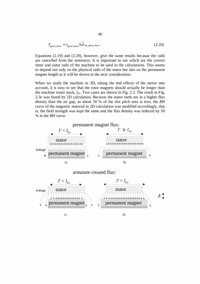
When we study the machine in 3D, taking the end effects of the motor intoaccount, it is easy to see that the rotor magnets should actually be longer thanthe machine stator stack, lFe. Two cases are shown in Fig. 2.3. The result in Fig.2.3e was found by 2D calculation. Because the stator teeth are in a higher fluxdensity than the air gap, as about 50 % of the slot pitch area is iron, the BHcurve of the magnetic material in 2D calculation was modified accordingly, thatis, the field strength was kept the same and the flux density was reduced by 50% in the BH curve.
permanent magnet
stator stator
permanent magnet
permanent magnet flux:
permanent magnet
stator stator
permanent magnet
armature created flux:
a) b)
c) d)
leakage
leakage
δ
l' < lFe
l' < lFe l' > lFe
Fell' ≥
41
00.10.20.30.40.50.60.70.80.9
1
0 10 20 30 40 50 60 70Distance (mm)
Mag
netic
flux
den
sity
(T)
Rotor length 60 mmRotor length 64 mm
e)
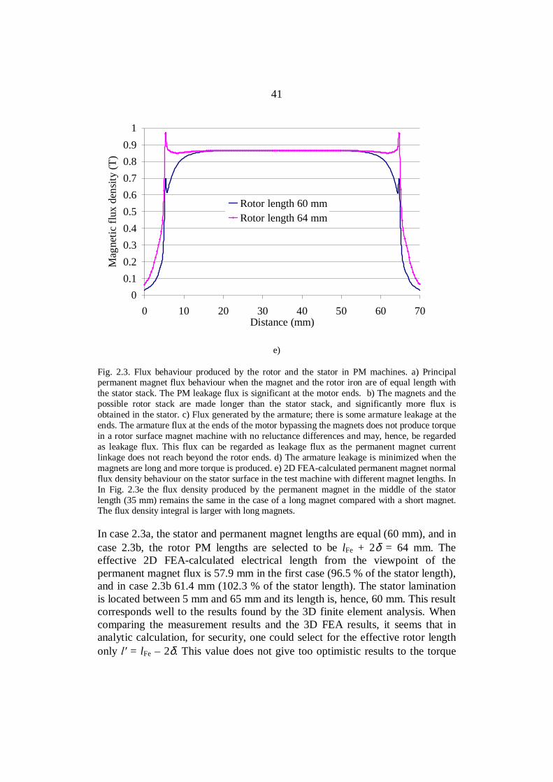
Fig. 2.3. Flux behaviour produced by the rotor and the stator in PM machines. a) Principalpermanent magnet flux behaviour when the magnet and the rotor iron are of equal length withthe stator stack. The PM leakage flux is significant at the motor ends. b) The magnets and thepossible rotor stack are made longer than the stator stack, and significantly more flux isobtained in the stator. c) Flux generated by the armature; there is some armature leakage at theends. The armature flux at the ends of the motor bypassing the magnets does not produce torquein a rotor surface magnet machine with no reluctance differences and may, hence, be regardedas leakage flux. This flux can be regarded as leakage flux as the permanent magnet currentlinkage does not reach beyond the rotor ends. d) The armature leakage is minimized when themagnets are long and more torque is produced. e) 2D FEA-calculated permanent magnet normalflux density behaviour on the stator surface in the test machine with different magnet lengths. InIn Fig. 2.3e the flux density produced by the permanent magnet in the middle of the statorlength (35 mm) remains the same in the case of a long magnet compared with a short magnet.The flux density integral is larger with long magnets.
In case 2.3a, the stator and permanent magnet lengths are equal (60 mm), and incase 2.3b, the rotor PM lengths are selected to be lFe + 2δ = 64 mm. Theeffective 2D FEA-calculated electrical length from the viewpoint of thepermanent magnet flux is 57.9 mm in the first case (96.5 % of the stator length),and in case 2.3b 61.4 mm (102.3 % of the stator length). The stator laminationis located between 5 mm and 65 mm and its length is, hence, 60 mm. This resultcorresponds well to the results found by the 3D finite element analysis. Whencomparing the measurement results and the 3D FEA results, it seems that inanalytic calculation, for security, one could select for the effective rotor lengthonly = lFe – 2δ. This value does not give too optimistic results to the torque

42
and back-emf. The practical measurements in this case confirm that the analyticcalculations give the best results when = lFe – 2δ = 56 mm is selected for therotor length.
The traditional advice of calculating the effective length = lFe + 2δ is given forinstance in (Pyrhönen, Jokinen, Hrabovcová 2008). This equation is valid formachines having stator and rotor current linkages longer than the laminationstacks. It is, however, not valid for rotor surface permanent magnet machinesunless the permanent magnets are considerably longer than the stator stack.This can be easily understood as in traditional machines the stator and rotorcurrent linkages reach beyond the stator and rotor stacks as the windings haveto travel straight towards the end windings. In the case of permanent magnetexcitation and equally long PM and lFe, the PM and armature leakages make themachine rotor current linkage look shorter as it was shown above. In the case ofthe test machine studied in this thesis, the traditional equation l = lFe + 2δcould be used if the rotor and permanent magnet lengths were lFe + 4δ, which inthis case would mean that the rotor should be 68 mm long while the statorlamination is 60 mm long and the air gap is 2 mm. The observation of the PMmachine rotor length is important as it gives practical guidelines for motordesigners in selecting the permanent magnet dimensions.
The above observation also shows a new source for the stator leakage. Whencalculating the stator magnetizing inductance, = lFe + 2δ can be used, but theflux in the end areas of the stator does not effectively participate in the energyconversion, and should hence be regarded as leakage flux, Fig. 2.3c. Thus, thelength of the magnets affects the leakage of the machine at least in principle,because lengths of about 1.5δ (Fig. 2.3e) at both ends of the stator (subtractedfrom the traditional effective length = lFe + 2δ) do not take part in the torqueproduction but carry flux, which is traditionally considered the main flux butchanges here to leakage. Hence, the magnetizing inductance should becalculated by = lFe – 2δ.
When both the stator lamination stack and the rotor permanent magnets have anequal length of 60 mm, the rotor magnets are seen as 56 mm long. Thus, whencalculating the stator magnetizing inductance, the value of 56 mm should beused. By applying = lFe + 2δ in the calculation of the stator magnetizinginductance, the proportion lFe + 2δ – (lFe – 2δ) = 4δ of the magnetic length ofthe traditional stator length produces leakage instead of magnetizinginductance.
In analytical calculation, it seems that when calculating with the geometricmean radius, the errors made in the calculation of the length when using lFe
43
compensate each other and a good result for the torque is found. This, however,is somewhat an erroneous method as the above study has shown. The correctway of performing the analytical calculation could be to use the arithmeticmean radius and take the PM leakage into account by shortening the effectivestack length in the case of magnets of equal length. If the magnets are madelonger than the stator stack, it is possible to directly apply the arithmetic meanradius and the real length of the stack in the calculation or to increase theeffective lamination length even further if the magnets are long compared withthe stator stack.
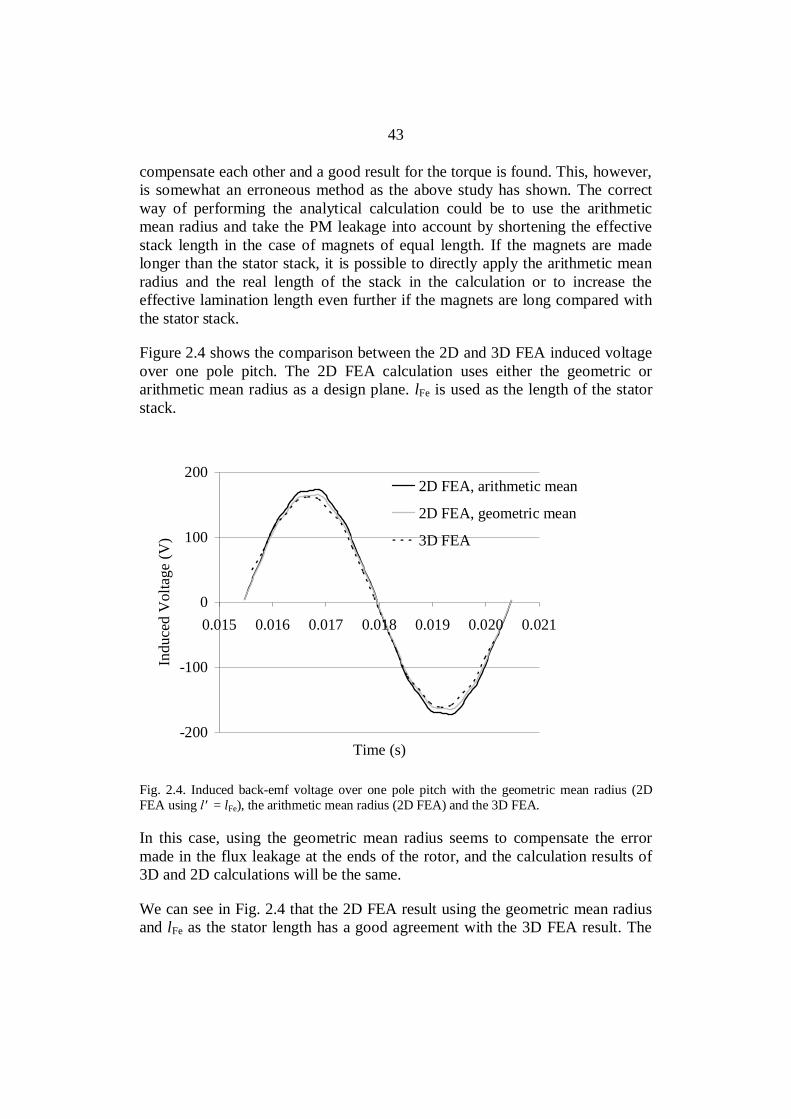
Figure 2.4 shows the comparison between the 2D and 3D FEA induced voltageover one pole pitch. The 2D FEA calculation uses either the geometric orarithmetic mean radius as a design plane. lFe is used as the length of the statorstack.
-200
-100
0
100
200
0.015 0.016 0.017 0.018 0.019 0.020 0.021
Time (s)
Indu
ced
Vol
tage
(V)
2D FEA, arithmetic mean
2D FEA, geometric mean
3D FEA
Fig. 2.4. Induced back-emf voltage over one pole pitch with the geometric mean radius (2DFEA using = lFe), the arithmetic mean radius (2D FEA) and the 3D FEA.
In this case, using the geometric mean radius seems to compensate the errormade in the flux leakage at the ends of the rotor, and the calculation results of3D and 2D calculations will be the same.
We can see in Fig. 2.4 that the 2D FEA result using the geometric mean radiusand lFe as the stator length has a good agreement with the 3D FEA result. The

44
arithmetic mean radius with the 2D FEA and = lFe results in a greater fluxthan the geometric radius with 2D or 3D. In this study, the arithmetic meanradius is used as a design plane from now on, and the effective length of thestator stack seen from the rotor is reduced according to the previous study =lFe – 2δ. The arithmetic mean radius can be used, because the magnet width tothe pole pitch ratio in the axial flux machine studied is kept constant at differentradii. The induced back electromagnetic forces seem to be in good agreementwith radial and axial flux machines when using the arithmetic mean radius as adesign plane in 2D and the reduced effective stack length (Fig. 2.5).
-200
-100
0
100
200
0.015 0.016 0.017 0.018 0.019 0.020 0.021
Time (s)
Indu
ced
Vol
tage
(V)
2D FEA, arithmetic mean
2D FEA, arithmetic mean,shorter stator stack3D FEA
Fig. 2.5. Induced back-emf voltage over one pole pitch with the arithmetic mean radius (2DFEA using = lFe), the arithmetic mean radius (2D FEA using = lFe – 2δ) and the 3D FEA.
Axial flux machines could also be calculated applying analytical or 2D tools byreplacing the actual 3D analysis by a number of 2D analyses as Parviainen(2005) and Kurronen (2003) did. From the quasi-3D modelling point of view,the axial flux PM machine can be considered to be composed of several linearmachines (without end effects) connected in parallel. The overall performanceof the axial flux machine is obtained by summing the performance of individuallinear machines. The approach allows taking into account different magnetshapes and variation of tooth width in the direction of the machine radius(Parviainen 2005).
45
2.2 Analytical calculation of the magnetic flux density in the air gap
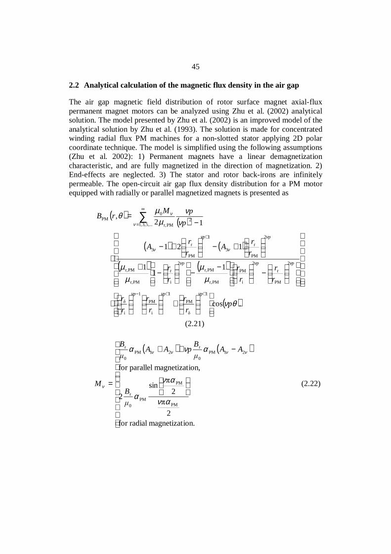
The air gap magnetic field distribution of rotor surface magnet axial-fluxpermanent magnet motors can be analyzed using Zhu et al. (2002) analyticalsolution. The model presented by Zhu et al. (2002) is an improved model of theanalytical solution by Zhu et al. (1993). The solution is made for concentratedwinding radial flux PM machines for a non-slotted stator applying 2D polarcoordinate technique. The model is simplified using the following assumptions(Zhu et al. 2002): 1) Permanent magnets have a linear demagnetizationcharacteristic, and are fully magnetized in the direction of magnetization. 2)End-effects are neglected. 3) The stator and rotor back-irons are infinitelypermeable. The open-circuit air gap flux density distribution for a PM motorequipped with radially or parallel magnetized magnets is presented as
( )( )
( ) ( )
( ) ( )
( ).cos
11
1
121
12,
1
PM
1
i
PM
1
i
2
PM
r
2
i
PM
PMr,
PMr,2
i
r
PMr,
PMr,
2
PM
r3
1
PM
r3
,...5,3,12
PMr,
0PM
θν
µµ
µµ
νν
µµ
θ
ννν
ννν
ν
ν
ν
ν
ν
ν
pr
rr
rrr
rr
rr
rr
rrA
rrA
ppMrB
ppp
ppp
pp
+
⋅
−
−−
−
+
+−
+−
⋅
−=
++−
+
∞
=∑
(2.21)
( ) ( )
−++
=
ion.magnetizatradialfor2
2sin
2
ion,magnetizatparallelfor
PM
PM
PM0
r
21PM0
r21PM
0
r
αν
αν
α
ανα νννν
νB
AABpAAB
M (2.22)
46
( )
( )p
p
pp
A
21
21sin
PM
PM
1
αν
αν
ν
+
+
= , (2.23)
( )
( )p
p
pp
A
21
21sin
PM
PM
2
αν
αν
ν
−
−
= , (2.24)
+
−
=
radial,for
parallel,for11 r
3
ppM
Mp
pA
ννν
νν
ν
ν (2.25)
( )
+
=
radial,for
2
2sin
2
parallel,for
PM
PM
PM0
r
21PM0
r
r
αν
αν
α
α νν
νB
AAB
M (2.26)
p
PMPM τ
αb
= , (2.27)
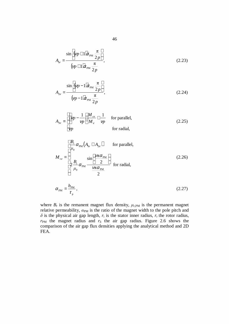
where Br is the remanent magnet flux density, r,PM is the permanent magnetrelative permeability, PM is the ratio of the magnet width to the pole pitch and is the physical air gap length, ri is the stator inner radius, rr the rotor radius,
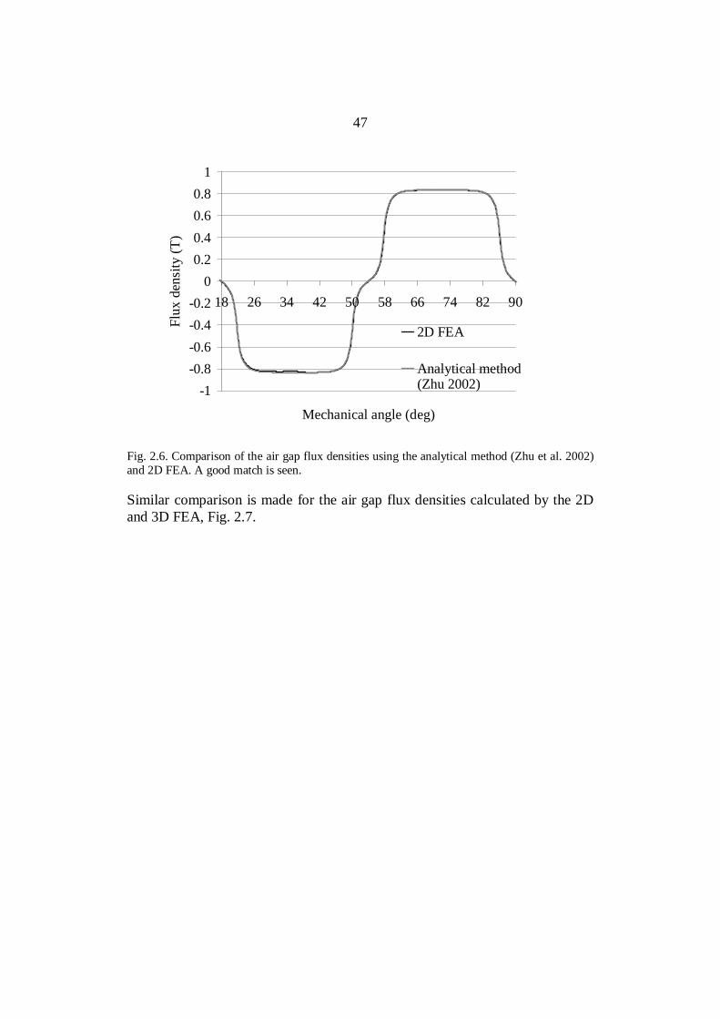
rPM the magnet radius and r the air gap radius. Figure 2.6 shows thecomparison of the air gap flux densities applying the analytical method and 2DFEA.
47
-1-0.8-0.6-0.4-0.2
00.20.40.60.8
1
18 26 34 42 50 58 66 74 82 90
Mechanical angle (deg)
Flux
den
sity
(T)
2D FEA
Analytical method(Zhu 2002)
Fig. 2.6. Comparison of the air gap flux densities using the analytical method (Zhu et al. 2002)and 2D FEA. A good match is seen.
Similar comparison is made for the air gap flux densities calculated by the 2Dand 3D FEA, Fig. 2.7.

48
-1-0.8-0.6-0.4-0.2
00.20.40.60.8
1
18 26 34 42 50 58 66 74 82 90
Mechanical angle (deg)
Flux
den
sity
(T)
2D FEA
3D FEA
Fig. 2.7. Comparison of the air gap flux densities by the 2D and 3D FEA. The coarse form ofthe 3D result is a consequence of sparse elements.
Figures 2.6 and 2.7 show that the presented analytical estimation and the 2DFEA give quite a good estimation for the air gap flux density of a concentratedwinding axial flux machine with a smooth air gap.
2.2.1 Slotting effect
The effect of the stator slots on no-load magnetic field distribution isinvestigated. The air gap flux density always drops at stator slot openings, andthis effect has a significant influence on the values of the flux and the inducedvoltage in the analytical calculation. For this reason, it is important toaccurately model the air gap flux density. Accurate calculation of the statorslotting effect is also needed for calculating the possible cogging torque, Joulelosses in PMs, vibration, noise and forces affecting the windings, teeth and theyoke.
In 1993, Zhu and Howe introduced two-dimensional relative permeancefunctions, which take into account the effects of stator slotting in the air gapflux density. The equation is based on the relative permeance functionpresented by Heller and Hamata (1977). The specific slot permeance variationdue to the stator slots and a smooth rotor is written according to Zhu and Howe(1993) as
49
( )
( ) ( )
≤≤≤≤
−−
=/20.8for
0.80for
8.0cos1
,
t00
0
00
ααααα
αα
ββ
αλ
rr
r (2.28)
where the air gap flux density is assumed to vary with the circumferentialcoordinate , PM00 /δµ= , 0 = b1/ri, t = u/ri, where b1 is slot opening width.The air gap is defined here as
PMr,
PMPM µ
δδ h+= , (2.29)
where hPM is the height of permanent magnet. The function (r) is defined at theaxis of a stator slot, and it depends on the radial position. The function (r)using the Schwarz–Christoffel (SC) conformal mapping technique is defined as
( )
+
+
−=2
2
PM
1 12
1
1121)(
vbr
δ
β . (2.30)
The coefficient v is iterated from
122
1
PM
1
PM22
22 2arctan
2ln
21
by
vav
bbvvavva
=+
+−+
++ δδ, (2.31)
where
2
1
PM2 21
+=
ba δ (2.32)
and y is given as
PMi δ+−= rry (2.33)
50
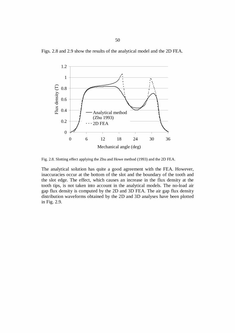
Figs. 2.8 and 2.9 show the results of the analytical model and the 2D FEA.
0
0.2
0.4
0.6
0.8
1
1.2
0 6 12 18 24 30 36
Mechanical angle (deg)
Flux
den
sity
(T)
Analytical method(Zhu 1993)2D FEA
Fig. 2.8. Slotting effect applying the Zhu and Howe method (1993) and the 2D FEA.
The analytical solution has quite a good agreement with the FEA. However,inaccuracies occur at the bottom of the slot and the boundary of the tooth andthe slot edge. The effect, which causes an increase in the flux density at thetooth tips, is not taken into account in the analytical models. The no-load airgap flux density is computed by the 2D and 3D FEA. The air gap flux densitydistribution waveforms obtained by the 2D and 3D analyses have been plottedin Fig. 2.9.
51
0.0
0.2
0.4
0.6
0.8
1.0
1.2
1.4
0 6 12 18 24 30 36
Mechanical angle (deg)
Flux
den
sity
(T)
2D FEA3D FEA
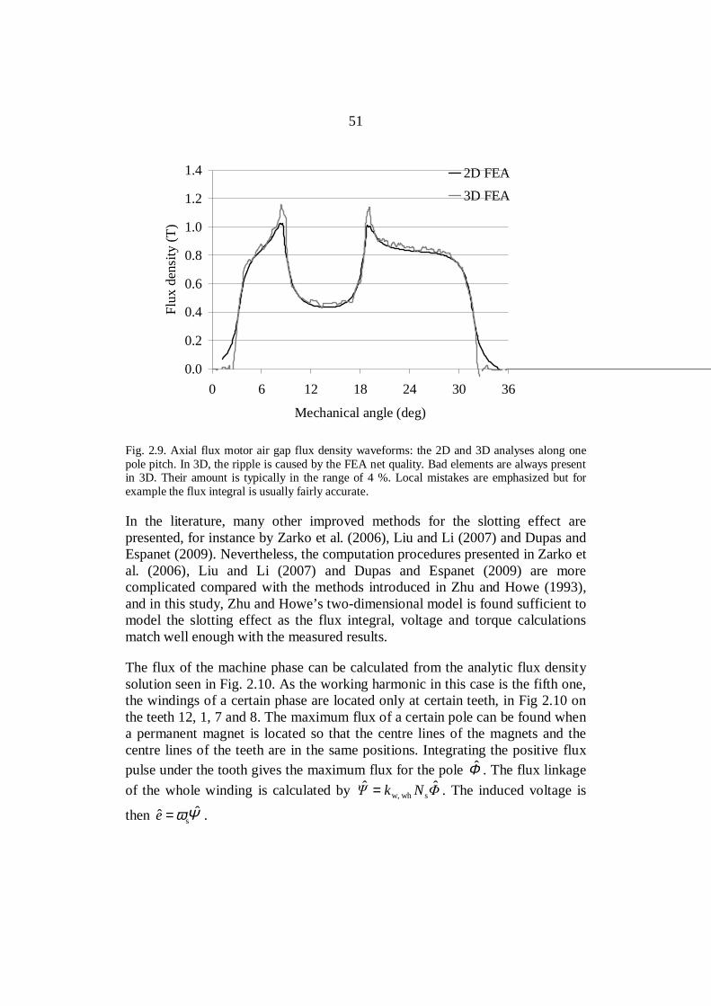
Fig. 2.9. Axial flux motor air gap flux density waveforms: the 2D and 3D analyses along onepole pitch. In 3D, the ripple is caused by the FEA net quality. Bad elements are always presentin 3D. Their amount is typically in the range of 4 %. Local mistakes are emphasized but forexample the flux integral is usually fairly accurate.
In the literature, many other improved methods for the slotting effect arepresented, for instance by Zarko et al. (2006), Liu and Li (2007) and Dupas andEspanet (2009). Nevertheless, the computation procedures presented in Zarko etal. (2006), Liu and Li (2007) and Dupas and Espanet (2009) are morecomplicated compared with the methods introduced in Zhu and Howe (1993),and in this study, Zhu and Howe’s two-dimensional model is found sufficient tomodel the slotting effect as the flux integral, voltage and torque calculationsmatch well enough with the measured results.
The flux of the machine phase can be calculated from the analytic flux densitysolution seen in Fig. 2.10. As the working harmonic in this case is the fifth one,the windings of a certain phase are located only at certain teeth, in Fig 2.10 onthe teeth 12, 1, 7 and 8. The maximum flux of a certain pole can be found whena permanent magnet is located so that the centre lines of the magnets and thecentre lines of the teeth are in the same positions. Integrating the positive fluxpulse under the tooth gives the maximum flux for the pole Φ . The flux linkageof the whole winding is calculated by Nk ˆˆ
s whw,= . The induced voltage is
then Ψω ˆˆ s=e .

52
-1.5
-1.0
-0.5
0.0
0.5
1.0
1.5
0 100 200 300 400 500 600 700
Flux
den
sity
(T)
1 2 3 4 5 6 7 8 9 10 11 12 1
U -U-U U U -UU -U
Fig 2.10 Air gap flux density and the permanent magnet positions of a radial flux machine or anaxial flux machine at a certain radius. The x-axis co-ordinate is given in mm for the machineobserved. Calculating the maximum flux of a pole can be done in such a pole where the magnetand the tooth observed are aligned (in this case between 200 mm and 300 mm).
In radial flux machines the width of the skewed magnets and in axial fluxmachines the flux linkage and the voltage are calculated from the flux densitydistribution and the winding arrangements are solved slice-wise (Kurronen2003). In radial flux machines with no skewing the flux can be calculatedsimply in one plane.
2.3 Torque and inductances
In a rotor surface magnet machine, the direct- and quadrature-axis magnetizinginductances (Lmd, Lmq) and the stator leakage inductance L form together thesynchronous inductances Ld and Lq, which can be used in the evaluation of themachine torque production capabilities in analytical calculations (Gieras andWing 1997, Hendershot and Miller 1994). The torque capability is inverselyproportional to the inductances
( )
−+= δδ
ω2sin11
2)sin(
dq
2s
d
sPM2
s LLU
LUEmpT , (2.34)
53
where s is the stator angular frequency, is the load angle, EPMelectromagnetic force and Us the supply line phase voltage. The torque isdivided into two parts: excitation torque and reluctance torque. The excitationtorque (the first term in 2.34) developed is generated by the interaction betweenthe magnets and the current, and represents usually most of the total steady-state torque available. The reluctance torque is additional torque and resultsfrom the saliency (the second term in 2.34 – inductance difference). Despite theslight permeability deviation of the permanent magnet from the permeability ofvacuum (µPM ≈ 1.05µ0) for rotor-surface-mounted magnets, the direct- andquadrature axis inductances (Ld, Lq) can, in practice, be supposed to be equalwithout making a major mistake, and hence, no saliency is assumed. In practice,there may be inductance differences caused by the saturation of iron parts(Parviainen 2005). It is assumed also in this study that the two series-connectedstators are equal measured by the magnetic parameters. In practice, there couldbe differences caused by the construction, assembly problems and so on(Parviainen 2005).
For small machines, where the per unit stator resistance is larger than 0.01, thestator resistance should be taken into account in the torque equation (Gieras andWing (1997)).
The equivalent air gap is defined as (Pyrhönen, Jokinen, Hrabovcová 2008)
+=′
PMr,
PMCPM µ
δδhk , (2.35)
and the effective air gap length taking also the average effects of iron of themagnetic circuit into account
aveFe,r,
mf
PMr,
PMCef µµ
δδlhk +
+= (2.36)
where kC is the Carter factor and lmf main flux path length.
+−=
21
1
1
21ln2
2arctan2
δδ
δκ
bb
b (2.37)
1u
uC b
kκτ
τ−
= , (2.38)
54
where is the factor for reduction of slot opening.
Magnetizing inductance
Magnetizing inductance for an integral slot winding multiphase machineaccording to (Pyrhönen, Jokinen, Hrabovcová 2008) is solved as
( )2sw1
ef
p0md '2 Nkl
pL
δτ
= , (2.39)
where µ0 is the permeability of air, τp is the pole pitch and is the effectivelength of the stator core depending on the rotor construction as discussed above.In a 12-10-machine, the mutual coupling is established in a different waycompared with an integral slot winding machine, but the coupling still exists.However, using the pole pitch width τp in the calculation of the magnetizinginductance of a concentrated winding machine may lead to too large aninductance value. Equation (2.39) assumes sinusoidal flux distribution along thewhole pole pitch. This, however, is not the case in concentrated windingmachines, where the flux is concentrated mainly on the tooth area in the air gap.We may here refer to Fig. 1.2 in Chapter 1; it helps to understand the main fluxbehaviour of concentrated winding machines, even though the figure showsmainly the PM flux. In concentrated winding machines, the air gap area throughwhich the flux travels to produce flux linkage is the area spanned by the coilsQ/m through the areaτu , as illustrated in Fig. 3.5. By taking such an approach,the magnetizing inductance for a three-phase machine can be solved as(Hanselmann (2003) and Salminen (2004))
( )2swhw,
ef
u0md '2 Nkl
mQL
δ
τ= , (2.40)
which is proposed for concentrated winding machines instead of Eq. (2.39). Theeffective air gap is defined by (2.36).
Leakage inductances
In this work, modified leakage inductance equations are given for aconcentrated winding machine based on Vogt (1996) and Richter (1954, 1963,1967). The leakage inductance L can be divided into five components, whichare according to Richter (1954) air gap leakage inductance, slot leakageinductance, end winding leakage inductance, tooth tip leakage inductance and
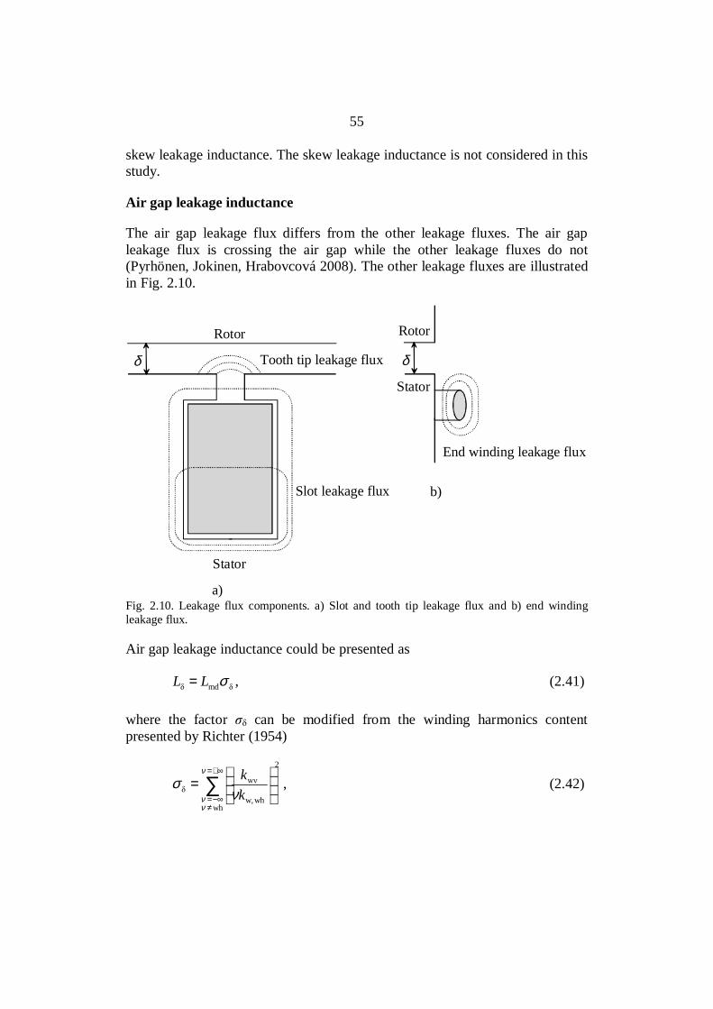
55
skew leakage inductance. The skew leakage inductance is not considered in thisstudy.
Air gap leakage inductance
The air gap leakage flux differs from the other leakage fluxes. The air gapleakage flux is crossing the air gap while the other leakage fluxes do not(Pyrhönen, Jokinen, Hrabovcová 2008). The other leakage fluxes are illustratedin Fig. 2.10.
δ
Rotor
Stator
Tooth tip leakage flux
Slot leakage flux
End winding leakage flux
Rotor
Stator
a)
b)
δ
Fig. 2.10. Leakage flux components. a) Slot and tooth tip leakage flux and b) end windingleakage flux.
Air gap leakage inductance could be presented as
mdσLL = , (2.41)
where the factor can be modified from the winding harmonics contentpresented by Richter (1954)
∑+∞=
≠−∞=
=
ν
νν ν
σwh
2
whw,kk , (2.42)
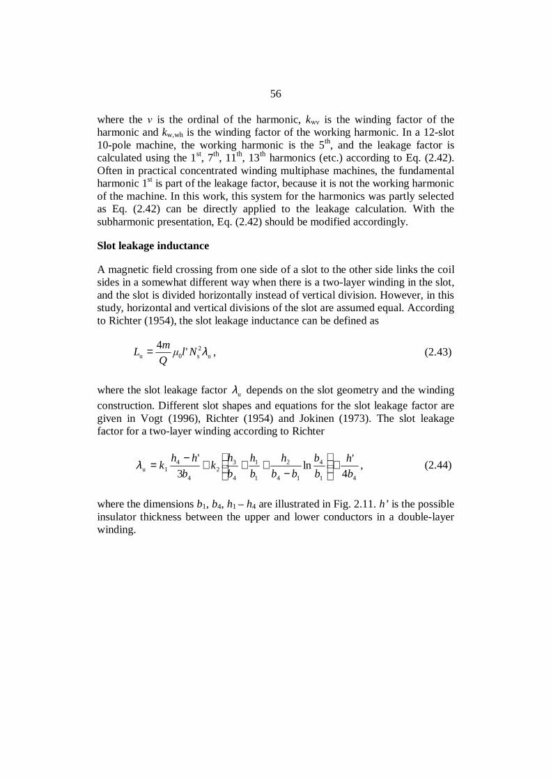
56
where the is the ordinal of the harmonic, k is the winding factor of theharmonic and kw,wh is the winding factor of the working harmonic. In a 12-slot10-pole machine, the working harmonic is the 5th, and the leakage factor iscalculated using the 1st, 7th, 11th, 13th harmonics (etc.) according to Eq. (2.42).Often in practical concentrated winding multiphase machines, the fundamentalharmonic 1st is part of the leakage factor, because it is not the working harmonicof the machine. In this work, this system for the harmonics was partly selectedas Eq. (2.42) can be directly applied to the leakage calculation. With thesubharmonic presentation, Eq. (2.42) should be modified accordingly.
Slot leakage inductance
A magnetic field crossing from one side of a slot to the other side links the coilsides in a somewhat different way when there is a two-layer winding in the slot,and the slot is divided horizontally instead of vertical division. However, in thisstudy, horizontal and vertical divisions of the slot are assumed equal. Accordingto Richter (1954), the slot leakage inductance can be defined as
u2s0u '4 λNl
QmL = , (2.43)
where the slot leakage factor uλ depends on the slot geometry and the windingconstruction. Different slot shapes and equations for the slot leakage factor aregiven in Vogt (1996), Richter (1954) and Jokinen (1973). The slot leakagefactor for a two-layer winding according to Richter
41
4
14
2
1
1
4
32
4
41u 4
'ln3
'bh
bb
bbh
bh
bh
kb
hhk +
−
+++−
=λ , (2.44)
where the dimensions b1, b4, h1 –h4 are illustrated in Fig. 2.11. h’ is the possibleinsulator thickness between the upper and lower conductors in a double-layerwinding.
57
b4
h4
h2
b1
h1
h3
Fig. 2.11. Slot dimensions.
The factors k1 and k2 can be calculated as
835
1gk +
= (2.45)
21
2gk +
= . (2.46)
According to Richter (1967), a “two-layer” factor, which multiplies thepermeance between the coils in the slot, to take into account the difference ofthe phase shift of two coils in the same slot, can be found as
∑=
=q
nqg2
1ncos2
1 γ . (2.47)
The angle n is the temporal phase shift between the currents of the coil sides.The summation includes all coil sides of one phase. The slot leakage inductanceis calculated independently for each slot connected in the winding section underobservation. Equation (2.47) has to be modified so that it suits a concentratedwinding. This can be done by comparing the winding construction of the 12-slot10-pole machine with an integral slot winding with q = 2 with short-pitching

58
W/τp = 5/6, where W is the coil width. Figure 2.12 illustrates the phase (A)winding constructions of these two machines (q = 0.4 and q = 2 W= 5/6).
… …
a)
… …
b)
Fig. 2.12. a) All coils in one phase (U) for a concentrated winding q = 0.4 and b) All coils inone phase (U) for an integral slot winding q = 2, W/τp = 5/6.
We modify Eq. (2.47) into
∑=
=mQ
n
mQg
1ncos1
γ (2.48)
If semi-magnetic slot wedges of a width bwedge = b1 are used, the slot openingwidth b1 can be calculated as b1 = bwedge/µr, wedge.
End winding leakage inductance
The end winding leakage flux is created by the magnetic field that surrounds acoil after it leaves one slot and before it enters another slot. The end winding ofthe prototype machine is illustrated in Fig. 2.13.
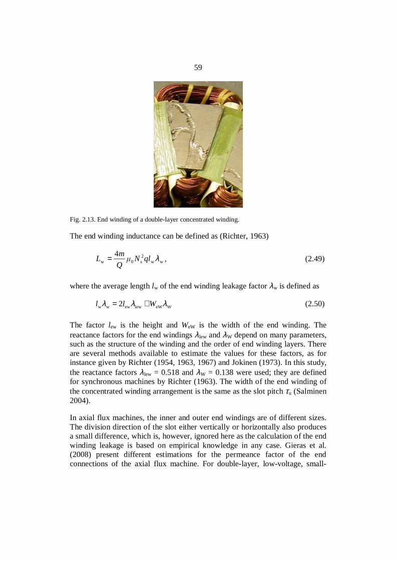
59
Fig. 2.13. End winding of a double-layer concentrated winding.
The end winding inductance can be defined as (Richter, 1963)
ww2s0w
4 λqlNQmL = , (2.49)
where the average length lw of the end winding leakage factor λw is defined as
WeWlewewww 2 λλλ Wll += (2.50)
The factor lew is the height and WeW is the width of the end winding. Thereactance factors for the end windings λlew and λW depend on many parameters,such as the structure of the winding and the order of end winding layers. Thereare several methods available to estimate the values for these factors, as forinstance given by Richter (1954, 1963, 1967) and Jokinen (1973). In this study,the reactance factors λlew = 0.518 and λW = 0.138 were used; they are definedfor synchronous machines by Richter (1963). The width of the end winding ofthe concentrated winding arrangement is the same as the slot pitch τu (Salminen2004).
In axial flux machines, the inner and outer end windings are of different sizes.The division direction of the slot either vertically or horizontally also producesa small difference, which is, however, ignored here as the calculation of the endwinding leakage is based on empirical knowledge in any case. Gieras et al.(2008) present different estimations for the permeance factor of the endconnections of the axial flux machine. For double-layer, low-voltage, small-

60
and medium-power machines, the permeance factors of the inner and outerconnections according to Gieras et al. (2008) are
−≈
inew,
inc,inw,
2117.0lw
λ (2.51)
−≈
outew,
outc,outw,
2117.0lw
λ (2.52)
where lew,in is the length of the inner end connection and lew,out the length of theouter end connection, wc,in the inner coil span and wc,out the outer coil span. Thetotal permeance factor is the sum of Eqs. (2.51) and (2.52)
outw,inw,w λλλ += (2.53)
Both Eqs. (2.50) and (2.53) lead to quite similar results in the prototypemachine.
Tooth-tip leakage inductance
Tooth-tip leakage inductance is produced by the leakage flux penetrating via theair gap to the next tooth. The tooth tip inductance of the phase coil is by Richter(1967)
z2s0z '4 λNl
QmL = . (2.54)
According to Richter, the leakage inductance factor can be defined by
′+
′
=
1
PM
1
PM
2z
45
5
b
bk
δ
δ
λ , (2.55)
where PMδ ′ is defined according to Eq. (2.35). In a two-layer winding, some coilsides in a slot belong to two different phases, and thus, there occur differentcurrents in the same slot. The factor k2,, which takes this into account, iscalculated as presented in the slot leakage inductance section of this work.
61
2.4 Joule losses of permanent magnets
Eddy current losses in the rotor permanent magnets are caused by threedifferent reasons (Sahin et al. 2001, Arrilaga and Watson 2003, Nerg et al.2002). First, a concentrated winding stator produces a large amount of currentlinkage harmonics generated flux densities travelling across the permanentmagnets, thereby causing eddy currents. These are called winding harmonics.Secondly, the large slot openings cause flux density variations that induce eddycurrents in the permanent magnets. These are called permeance harmonics.Finally, frequency-converter-caused time harmonics in the stator currentwaveform cause extra losses in the rotor. In this study, however, frequency-converter-caused time harmonics are not analyzed. In general, present dayindustrial frequency converters use switching frequencies in the range of 3–4kHz. Such a switching frequency often produces an overall efficiencymaximum to an industrial variable speed drive as the sum of losses in theconverter and the motor is minimized (Slaets et al. 2000). In industrialinduction motors the frequency-converter-caused losses are concentrated,especially, on the rotor surface. Some increase in the stator copper and ironlosses can also be observed.
In a permanent magnet machine with no damper winding and with segmentedmagnets, the transient inductance is quite large – in the range of synchronousinductance – and hence, the motor current remains fairly sinusoidal.
Significant eddy-current losses in the PMs will not only affect the machineefficiency, but may also result in excessive heating, which could lead toirreversible deterioration in the machine performance, for instancedemagnetization of the magnets. Eddy current losses may occur also in the rotorunder the magnets. In this study, this is not considered, and non-conductingrotor material is used in the calculations. This is justified because in theprototype machine there is no iron in the rotor at all.
For practical reasons, in the following, the winding-harmonics-caused andpermeance-harmonics-caused losses will be studied separately even thoughsuch an approach may lead to a somewhat erroneous result because thewinding-harmonic-caused and the permeance-harmonic-caused fluxcomponents can either strengthen or cancel each other in the air gap, which,because of the nonlinearity of materials, can prevent the superposition of theloss components (Jokinen 1973).
Figure 2.14 illustrates permeance-harmonic-caused (no load, Br = 1.03) andwinding-harmonic-caused (rated load, Br = 0) PM Joule losses calculated by the
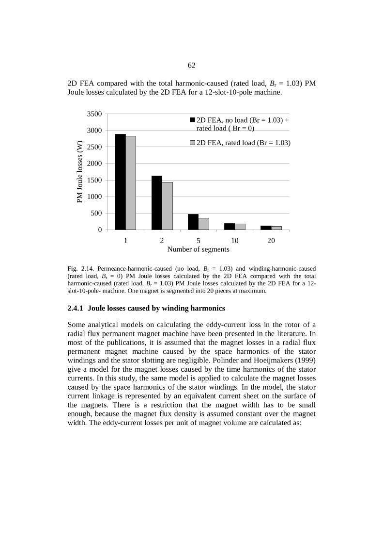
62
2D FEA compared with the total harmonic-caused (rated load, Br = 1.03) PMJoule losses calculated by the 2D FEA for a 12-slot-10-pole machine.
0
500
1000
1500
2000
2500
3000
3500
1 2 5 10 20Number of segments
PM Jo
ule
loss
es (W
)
2D FEA, no load (Br = 1.03) +rated load ( Br = 0)
2D FEA, rated load (Br = 1.03)
Fig. 2.14. Permeance-harmonic-caused (no load, Br = 1.03) and winding-harmonic-caused(rated load, Br = 0) PM Joule losses calculated by the 2D FEA compared with the totalharmonic-caused (rated load, Br = 1.03) PM Joule losses calculated by the 2D FEA for a 12-slot-10-pole- machine. One magnet is segmented into 20 pieces at maximum.
2.4.1 Joule losses caused by winding harmonics
Some analytical models on calculating the eddy-current loss in the rotor of aradial flux permanent magnet machine have been presented in the literature. Inmost of the publications, it is assumed that the magnet losses in a radial fluxpermanent magnet machine caused by the space harmonics of the statorwindings and the stator slotting are negligible. Polinder and Hoeijmakers (1999)give a model for the magnet losses caused by the time harmonics of the statorcurrents. In this study, the same model is applied to calculate the magnet lossescaused by the space harmonics of the stator windings. In the model, the statorcurrent linkage is represented by an equivalent current sheet on the surface ofthe magnets. There is a restriction that the magnet width has to be smallenough, because the magnet flux density is assumed constant over the magnetwidth. The eddy-current losses per unit of magnet volume are calculated as:

63
( )2
PM
2PM
2
2
2PMPM
PMPM d
d12
d1PM
PM
== ∫
−tBbxxJ
bk
b
b ρρ , (2.56)
where bPM is the magnet width, PM the permanent magnet resistivity and JPMthe current density. Equation (2.56) is comparable with the eddy-current lossesin laminated iron.
The analytical model for Joule loss prediction in permanent magnets inCartesian co-ordinates is based on a cross-section of a two-pole PM machine(Polinder and Hoeijmakers 1997, 1999, 2000) shown in Figure 2.15. Themagnets are numbered from 1 to NPM.
hPM
bPM
1
2
NPM
αPM
αs
αr
θαPM,1
Fig. 2.15. Cross-section of the two-pole PM machine (Polinder and Hoeijmakers 1999).

64
The total magnet losses are defined as
( )( )( )
( )( ) ( )( )
( )( ) ( )( )
−+
+
=
−≈ ∫
−
2
PMPM
2
PMPM
PM
2PMPMFe
r
2
2
2
rPM
2PM
PMFeecPM,
sinˆddsin
cosˆddsin
12
dcosˆdd
122
PM
PM
βαα
βαα
ρ
αβαρ
α
α
pBt
pp
pBt
ppbhlr
pBt
bhlprP
, (2.57)
where NPM is the number of magnet segments per pole and is the spatial anglebetween the stator and magnet field.
Further, at least the eddy-current losses in the magnets can be estimatedsimilarly as the eddy current losses in the iron if the depth of penetration ishigher than the magnet segment height hPM. The length of the magnet issubstantially larger than the magnet width bPM. Also the end effects arenegligible.
PM
222PMPM
ecPM, 12
ˆ
ρωBbVP ≈ , (2.58)
where VPM is the magnet volume. The angular frequency , is calculated for thephenomenon under study, and it is different for each harmonic, PM is theresistivity of the magnet material, and the magnetic flux density B is found bythe flux analysis.
The method introduced by Atallah et al. (2000) is also based on representing thestator current linkage distribution by an equivalent current sheet. Only thelosses caused by the stator current linkage space harmonics are analyzed.Analytical models also assume that in an actual machine the skin depthsassociated with most of the dominant stator space harmonics are usually greaterthan the magnet dimensions, and therefore the induced eddy currents areresistance limited so that their influence on the inducing magnetic fielddistribution is negligible. The eddy current loss per unit axial length in onemagnet is given by
)W/m(ddd2
2PMPM
2/
2/
/2
0ecPM,
PM
PM
PM
r
trrJP r
r
r
θρα
α∫∫∫
−
Ω
= (2.59)

65
( ) )W/m(1
acecPM, ∑∞
=
+=ν
νν PPP (2.60)
where
( )
( )
( )22
i
r
2r
2PM
2i
2
i
r2r
2i
2
i
r
22
PM
r
s
2PM
2i
2
i
PM
22rs2
s2
2PM
PM
PM20
2
c
s
ss
ss
1
-122
8
−
−
+
+
+
⋅
=
+
p
pp
pp
rr
rrrrrFrr
rr
rr
prr
rr
ppp
JmP
ν
ν
ν
ν
νν
νν
ν
ννρ
αµm
(2.61)
and
( )
=
≠+−
−
=
+−
1forln
1for22
1
sr
PM
ss
22
r
PMs
pr
r
pp
rr
F
p
ν
νν
ν
ν (2.62)
and

66
( )
( )
( )22
i
r2r
2PM
PMs
22
2ri
i
r
2
PM
r
s
2PMi
i
PM
22rs4
s4
2PM
PMPM
20
2
a
s
s
ss
1
2sin
-12
−−
⋅
+
+
⋅
−=
+
p
p
pp
rrrr
pGrr
rr
rr
prr
rr
ppp
JmP
νν
ν
νν
νν
αν
ν
ννρα
µm
(2.63)
and
( )
=
≠+−
−
=
+−
2forln
2for2
1
sr
PM
ss
2
r
PMs
pr
r
pp
rr
G
p
ν
νν
ν
ν . (2.64)
Here, the - sign applies to = 3k + m and + sign to = 3k –m. The value for m= ± 1 is dependent on the winding configuration (Toda et al. 2004). For the 12-slot-10-pole machine m = -1. The space harmonic order is , ps and pr are thefundamental numbers of pole pairs associated with the stator winding and therotor, is the rotor angular velocity and
νν wi
ssPM
ˆ2k
riN
J = . (2.65)
In a 12/10 machine ps = 1. Because the machine produces the harmonics +1, -5,+7 (and so on) and works with the fifth harmonic, Eqs. (2.61) and (2.63)contain the relative speeds of the harmonics bypassing the magnet. The fifthharmonic does not produce travelling stator harmonics in the magnets.
Ede et al. (2002) present a computationally efficient 3D technique to determinethe influence of the axial segmenting of the permanent magnets on the rotoreddy-current loss in concentrated winding PM machines. Axial segmentation ofthe permanent magnets of a surface-mounted magnet rotor has been shown to
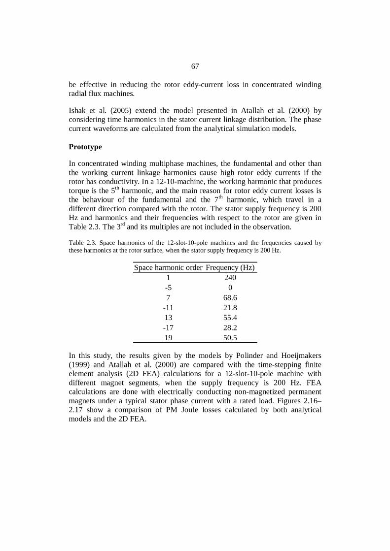
67
be effective in reducing the rotor eddy-current loss in concentrated windingradial flux machines.
Ishak et al. (2005) extend the model presented in Atallah et al. (2000) byconsidering time harmonics in the stator current linkage distribution. The phasecurrent waveforms are calculated from the analytical simulation models.
Prototype
In concentrated winding multiphase machines, the fundamental and other thanthe working current linkage harmonics cause high rotor eddy currents if therotor has conductivity. In a 12-10-machine, the working harmonic that producestorque is the 5th harmonic, and the main reason for rotor eddy current losses isthe behaviour of the fundamental and the 7th harmonic, which travel in adifferent direction compared with the rotor. The stator supply frequency is 200Hz and harmonics and their frequencies with respect to the rotor are given inTable 2.3. The 3rd and its multiples are not included in the observation.
Table 2.3. Space harmonics of the 12-slot-10-pole machines and the frequencies caused bythese harmonics at the rotor surface, when the stator supply frequency is 200 Hz.
Space harmonic order Frequency (Hz)1 240-5 07 68.6
-11 21.813 55.4-17 28.219 50.5
In this study, the results given by the models by Polinder and Hoeijmakers(1999) and Atallah et al. (2000) are compared with the time-stepping finiteelement analysis (2D FEA) calculations for a 12-slot-10-pole machine withdifferent magnet segments, when the supply frequency is 200 Hz. FEAcalculations are done with electrically conducting non-magnetized permanentmagnets under a typical stator phase current with a rated load. Figures 2.16–2.17 show a comparison of PM Joule losses calculated by both analyticalmodels and the 2D FEA.

68
0
500
1000
1500
2000
1 2 5 10 20Number of segments
PM Jo
ule
loss
es (W
)
2D FEAAtallah (2000)
Fig. 2.16. Stator-harmonic-caused PM Joule losses calculated analytically by the Atallah et al.(2000) method and the 2D FEA for a 12-slot-10-pole machine. One magnet is segmented into20 pieces at maximum.
0
50
100
150
200
5 10 20Number of segments
PM Jo
ule
loss
es (W
)
2D FEAAtallah (2000)Polinder (1999)
Fig. 2.17. Same results as in the previous figure calculated analytically by the methods byAtallah et al. (2000) and Polinder and Hoeijmakers (1999) and the 2D FEA for a 12-slot-10-pole machine. One magnet is segmented into 20 pieces at maximum.

69
Figures 2.16 and 2.17 show that the model by Atallah et al. (2000) isappropriate to analyze the PM Joule losses caused by space harmonics for alldifferent size segments. The model by Polinder and Hoeijmakers (1999) isappropriate when the magnet segments are so small that the magnetic fluxdensity can be considered constant over the magnet width, which is mentionedas a restriction in their publication (Polinder and Hoeijmakers 1999). Radialsegmentation of the permanent magnets of a surface-mounted magnet rotor hasbeen shown to be effective in reducing the rotor eddy-current loss as Atallah etal. (2000) and Polinder and Hoeijmakers (1999) have presented. In this work,the influence of the segmentation direction was also studied; tangentially andradially segmented magnets were investigated by practical measurements.
2.4.2 Joule losses caused by permeance harmonics
Joule losses generated in PMs because of stator slotting have been studied insome publications. Especially in concentrated winding machines with openslots, the air gap flux density pulsations owing to the slot openings are high, andthe Joule losses in the magnets caused by permeance harmonics have to betaken into account (Ishak et al. 2005, Reichert 2004, Deak et al. 2006, Deak etal. 2008). An analytical calculation model is presented by Markovic andPerriard (2008). In the Markovic and Perriard model it is assumed that only theslot opening influences the air gap magnetic field regardless of whether theteeth have crowns or not, in other words, the rest of the slot has no influence.Therefore, the slots can be treated as infinitely deep. The influence of slottingmay be taken into account by introducing a 2D permeance function thatmodulates the air gap flux density calculated by Zhu’s and Howe’s method(1993) in the analytical calculation. The permeance function is based on aFourier series presentation of the flux density under the slot opening. The meanloss of one magnet is obtained from a simple form:
∑
−=
nn
nbnb
KbvBhlP2
u
PM
PM
u2
PM
PM2r
2PMFe
ecPM, sin12
ˆ
ττ
ρ(2.66)
which includes
∑
−=
nn
nbnb
KMOD2
u
PM
PM
u2 sin1τ
τ (2.67)
where vr is the rotor surface speed and Kn the coefficients obtained from the 2Dmodulation function. MOD describes the proportion of losses caused by the
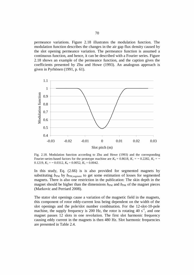
70
permeance variations. Figure 2.18 illustrates the modulation function. Themodulation function describes the changes in the air gap flux density caused bythe slot opening permeance variation. The permeance function is assumed acontinuous function, and hence, it can be described with a Fourier series. Figure2.18 shows an example of the permeance function, and the caption gives thecoefficients presented by Zhu and Howe (1993). An analogous approach isgiven in Pyrhönen (1991, p. 61).
0.4
0.5
0.6
0.7
0.8
0.9
1
1.1
-0.03 -0.02 -0.01 0 0.01 0.02 0.03
Slot pitch (m)
Mod
ulat
ion
func
tion
Fig. 2.18. Modulation function according to Zhu and Howe (1993) and the correspondingFourier-series-based factors for the prototype machine are K0 = 0.8618, K1 = − 0.2282, K2 = −0.1219, K3 = − 0.0312, K4 = 0.0052, K5 = 0.0042.
In this study, Eq. (2.66) is is also provided for segmented magnets bysubstituting bPM by bPM,segment to get some estimation of losses for segmentedmagnets. There is also one restriction in the publication: The skin depth in themagnet should be higher than the dimensions hPM and bPM of the magnet pieces(Markovic and Perriard 2008).
The stator slot openings cause a variation of the magnetic field in the magnets,this component of rotor eddy-current loss being dependent on the width of theslot openings and the pole/slot number combination. For the 12-slot-10-polemachine, the supply frequency is 200 Hz, the rotor is rotating 40 s-1, and onemagnet passes 12 slots in one revolution. The first slot harmonic frequencycausing eddy current in the magnets is then 480 Hz. Slot harmonic frequenciesare presented in Table 2.4.
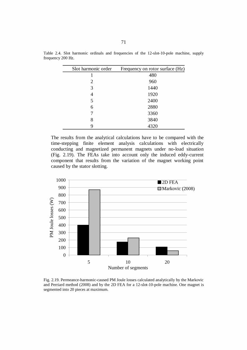
71
Table 2.4. Slot harmonic ordinals and frequencies of the 12-slot-10-pole machine, supplyfrequency 200 Hz.
Slot harmonic order Frequency on rotor surface (Hz)1 4802 9603 14404 19205 24006 28807 33608 38409 4320
The results from the analytical calculations have to be compared with thetime-stepping finite element analysis calculations with electricallyconducting and magnetized permanent magnets under no-load situation(Fig. 2.19). The FEAs take into account only the induced eddy-currentcomponent that results from the variation of the magnet working pointcaused by the stator slotting.
0100200300400500600700800900
1000
5 10 20Number of segments
PM Jo
ule
loss
es (W
)
2D FEAMarkovic (2008)
Fig. 2.19. Permeance-harmonic-caused PM Joule losses calculated analytically by the Markovicand Perriard method (2008) and by the 2D FEA for a 12-slot-10-pole machine. One magnet issegmented into 20 pieces at maximum.
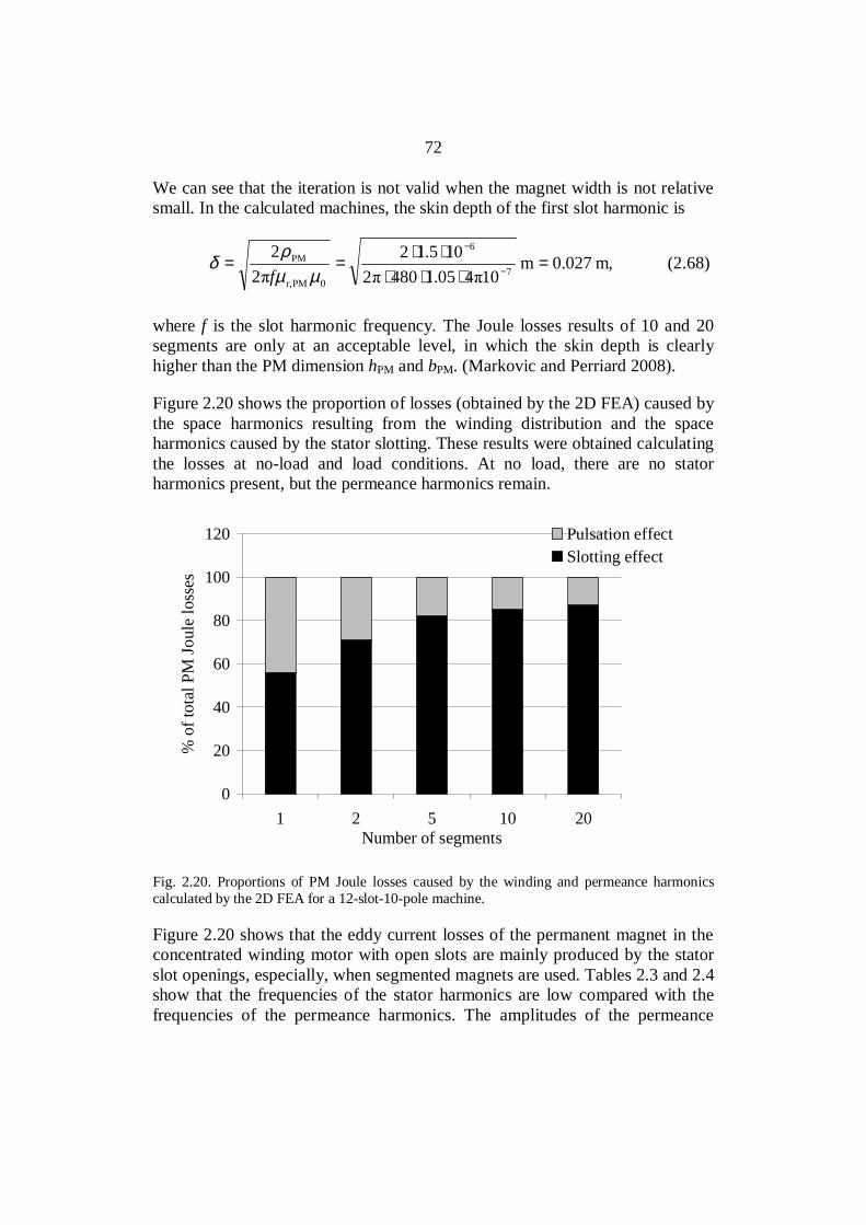
72
We can see that the iteration is not valid when the magnet width is not relativesmall. In the calculated machines, the skin depth of the first slot harmonic is
m,0.027m10405.14802
105.122
27
6
0PMr,
PM =⋅⋅⋅
⋅⋅==
−
−
µµρ
δf
(2.68)
where f is the slot harmonic frequency. The Joule losses results of 10 and 20segments are only at an acceptable level, in which the skin depth is clearlyhigher than the PM dimension hPM and bPM. (Markovic and Perriard 2008).
Figure 2.20 shows the proportion of losses (obtained by the 2D FEA) caused bythe space harmonics resulting from the winding distribution and the spaceharmonics caused by the stator slotting. These results were obtained calculatingthe losses at no-load and load conditions. At no load, there are no statorharmonics present, but the permeance harmonics remain.
0
20
40
60
80
100
120
1 2 5 10 20Number of segments
% o
f tot
al P
M Jo
ule
loss
es
Pulsation effectSlotting effect
Fig. 2.20. Proportions of PM Joule losses caused by the winding and permeance harmonicscalculated by the 2D FEA for a 12-slot-10-pole machine.
Figure 2.20 shows that the eddy current losses of the permanent magnet in theconcentrated winding motor with open slots are mainly produced by the statorslot openings, especially, when segmented magnets are used. Tables 2.3 and 2.4show that the frequencies of the stator harmonics are low compared with thefrequencies of the permeance harmonics. The amplitudes of the permeance

73
harmonics are also large compared with the stator harmonics. These factsexplain why the proportion of the slotting effect increases as the amount ofslices is increasing.
The amplitude of the permeance-harmonic-caused flux pulsation is largecompared with the amplitudes of the stator harmonics because the magnetizinginductance is low. Even the working harmonic armature reaction (Lmd,p.u. = 0.3)is small and, especially, other armature-harmonics-caused flux densities areconsiderably weaker than the permanent magnet density changes caused by theslot openings above the magnets, because the winding factors of the harmonicsare usually low.
2.5 Other losses
Winding losses
,3 2ssCu IRP = (2.69)
where Rs is the alternating current (AC) resistance for one phase winding and Isis the phase current (RMS). When the current frequency is high and theconductor cross-section is large enough, eddy-current losses are induced in thecopper as a result of skin and proximity effects.
Stator core losses
The losses include the hysteresis losses, the Joule losses and the excess losses.The iron losses are defined in the periodic state (time stepping magneticapplications over one complete period); Cedrat’s Flux2D is employed in finiteelement computations (Bertotti et al. 1991, Cedrat 2009). The iron losses arecalculated in a magnetic region during the analysis.
tttBk
ttBdk
TkfBkttP
T
TT
dd
)(dd
)(d12
1ˆd)(1
0
5.1
e
22
Feff2
h0
Fe ∫∫
+
+= σ
, (2.70)
where B is the maximum flux density in the element concerned, f thefrequency, Fe the conductivity, d the lamination sheet thickness, kh thecoefficient of hysteresis loss, ke the coefficient of excess loss and kf is the fillingfactor. The factors depend on the steel material applied.
The analytical equation for iron losses presented by Deng (1999) includes theharmonic effect of the flux densities

74
( )
5.1
RMS43
2
exe2
RMS2
ehehFe d
d
2dd
2ˆ
+
+=
tBk
tBkBfkkP α , (2.71)
where f and B are the frequency and peak value of the flux density, kh, ke, kexeand are constants determined by the loss data provided by the manufacturer.An empirical correction factor keh is applied to take into account the effect of
minor hysteresis loops on the hysteresis loss.RMSd
d
tB is the RMS value of the
rate of change of the flux density with respect to time in an AC cycle.
A different analytical equation for iron losses is presented by Pyrhönen,Jokinen, Hrabovcová (2008). Hysteresis losses can be written as
HyHy bfVP = . (2.72)
Empirical equations yield an approximation for the hysteresis loss
nBVfP ˆHy η= . (2.73)
where the exponent n varies typically between [1.5, 2.5], η being an empiricalconstant.
Joule losses
Fe
2222
Fe
2322
ecFe, 6
ˆ
6
ˆ
ρρBdfVBdfbh
P⋅
== . (2.74)
or
nn mBPP Fe,
2
n15Fe, T5.1
ˆ
= . (2.75)
Further, hysteresis and Joule losses together in the stator yoke and teeth
23
ys
2ys
15FeysFeys 505.1
=
fmB
PkP (2.76)

75
23
ts
2ts
15FetsFets 505.1
=
fmB
PkP (2.77)
The hysteresis losses are roughly proportional to the square of the fluxdensity, and the Joule losses are proportional to the square of the flux density.It is determined that both losses are proportional to the square of the fluxdensity. Further, a compromise is made with the power of the frequency. Thehysteresis losses are, in principle, directly proportional to the frequency, andJoule losses are proportional to the square of the frequency; thus, together thelosses are about proportional to f3/2. The iron coefficients are found by acurve-fitting approach of the material data from the manufacturer.
The iron losses calculated by Eq. (2.77) give the following values for the testmachine, Table 2.5. The remanent flux density of the PM at 20 ºC is Br20C =1.1 T in the no load situation and at 80 ºC, Br80C = 1.03 T in the rated loadsituation.
Table 2.5. Analytically calculated iron losses of the 12-slot-10-pole machines in no-load andrated load situations, the coefficients kFeys=1.5 and kFets=1.7 for yokes and teeth were selectedaccording to Müller et al. (2008). One magnet is segmented into 1 or 20 pieces.
Rotor equipped with PFeys/W PFets/W Single statoriron losses/W
Double statoriron losses/W
No load; bulkymagnets 80 230 310 630
No load; radiallysegmented magnets 80 220 290 580
Rated load; bulkymagnets 70 200 280 550
Rated load; radiallysegmented magnets 70 190 250 510
Additional losses
Additional losses are usually losses caused by the flux harmonics and other corelosses except stator eddy and hysteresis losses of the working harmonic. Theselosses vary significantly for different machines and various operatingconditions. The additional losses can be calculated by (Gieras and Wing 1997)
outadad PkP = , (2.78)
76
where the additional loss coefficient for PM machines kad = 0.03… 0.05 forsmall machines up to 10 kW, kad = 0.005… 0.01 for medium-speed machines upto 100 000 kW and kad = 0.003… 0.005 for large-power machines. The PMmachine type also has an effect on the coefficient.
Mechanical losses can be calculated by the equation
P = k Dr (lr + 0.6 τp)vr2 (2.79)
found for instance in (Pyrhönen, Jokinen, Hrabovcová 2008). k = 15 Ws2/m4
for totally enclosed fan-cooled small machines.
When the average diameter is used for Dro and the length 0.06 m, we obtain 220W.
2.6 Summary
Basic guidelines for the analytical calculation of axial flux concentratedwinding PM machines were introduced. It was shown that an axial flux PMmachine can be modelled as a radial flux PM machine by applying thearithmetic mean radius as a design plane. The analytical calculation of the airgap magnetic flux density for a non-slotted and slotted stator was presented.Equations for magnetizing inductance and different leakage inductancecomponents were presented. Special attention was paid to the evaluation ofpermanent magnet Joule losses. It was shown that a major part of the permanentmagnet Joule losses are due to the stator slotting when the motor is supplied bysinusoidal current. The frequency-converter-caused time harmonics are notanalyzed in this study. The analytical calculation results were verified bycomparing them with the numerical results obtained from the 2D and 3D FEA.
77
3 TORQUE CAPABILITIES OF DIFFERENT WINDINGCONSTRUCTIONS
There is discussion whether concentrated winding or integral slot winding PMmachines should be used for a certain application; this question is discussed inthis chapter with examples of machines having the number of slots per pole andphase varying from q = 0.25 to q = 2 and fixed motor outer dimensions. In thefollowing study, the mass of PM material, back emf and the stator outerdimensions are kept constant.
The end windings in a concentrated winding with q ≤ 0.5 are notably smallerthan in integral slot winding machines, which provides an opportunity of usinga large rotor and producing large torque in predetermined machine overalldimensions. The short end windings also guarantee low copper losses. Withcareful design, a very good torque quality of a concentrated winding machinecan be achieved.
This study, however, indicates that the torque production capability of integralslot windings is good compared with concentrated winding machines. Theremay also be problems with the rotor losses in concentrated winding machines asthe permanent magnet material flux density pulsates heavily in concentratedwinding machines, especially in open slot machines. Hence, the machinedesigner must be aware of all the factors and find a good design compromise. Itseems that because of high rotor magnet losses, concentrated machines suit bestfor low-speed high-torque applications if permanent magnet losses cannot belimited to a tolerable level at higher speeds.
This chapter addresses the behaviour of inductances and the maximumavailable pull-out torques of concentrated winding machines with q ≤ 0.5compared with integral slot winding machines. All the motors studied haverotor-surface-mounted magnets. Inductances and pull-out torques are calculatedfor concentrated winding machines q = 0.25, q = 0.29, q = 0.4 and q = 0.5 andintegral slot winding machines q = 1 and q = 2. The equations applied ininductance calculation were given in Chapter 2. The pull-out torques of somemachines are also verified by FEA calculations using Flux2D by CEDRAT(Salminen 2004). Tables 3.1 and 3.2 summarize the machines under study.
78
Table 3.1. Slot numbers Q of concentrated winding machines studied in the work.
q/p 4 5 6 7 8 10 11 12 13 14 15 16 21 240.25 12 18 24 360.29 12 24 360.4 12 24 360.5 12 18 24 36
Table 3.2. Slot numbers Q of integral slot winding machines studied in the work.
q/p 2 3 4 5 6 7 8 9 10 11 121 12 18 24 30 36 42 48 54 60 66 722 24 36 48 60 72 84 96 108 120 132 144
3.1 Machine parameters
All analyzed machines have the same frame size 225. This frame size is usuallyused in 50 Hz network-driven industrial induction machines with the ratedoutput torque of 150–400 Nm (ABB 2007) depending on the number of poles.With a higher amount of poles, the rotor in the same frame size, andcorrespondingly the torque, can be larger than in machines with two magneticpoles. The frame size specifies the outer diameter and overall length of themotor. The machine magnetic length and the air gap diameter were selected tobe constant parameters to keep the rotor volume equal for all the machines.Such an approach will indicate the torque capability differences betweendifferent constructions. The torque and volume dependence is presented as(Pyrhönen, Jokinen, Hrabovcová 2008)
r2r lkDT = (3.1)
where k is a machine type dependent constant, Dr is the rotor diameter and lr isthe rotor length. The equation shows that the torque is proportional to the rotordiameter squared and directly proportional to the rotor length, that is, thevolume of the rotor. The constant values used in the comparison are given inTable 3.3.

79
Table 3.3. Machine constant parameters.
Stator stack length, lFe 270 mmStator stack outer diameter, Do 364 mmStator stack inner diameter, Di 254 mmAir gap length, 1.2 mmThe amount of the permanentmagnet material, mPM
10.3 kg
Rated output power, Pout 45 kWRated speed, ns 400 min-1
Also the back-emf is used as a fixed parameter. It is set equal to or higher than0.9 of the supply voltage. To achieve the same back-emf for all the machines, inmachines with q = 0.5 and 0.25, more winding turns are required than inmachines with q = 0.4 and 0.29 because of the lower winding factor. Whenusing such fixed parameters, all the machines do not have an optimal design asfor instance the stator yoke flux density can be low in some designs;nevertheless, indication of the torque producing capability is found. The fluxdensities in the stator teeth and yoke were selected to be about 1.8 T and 1.6 T,respectively.
3.2 Inductances and torques of concentrated winding machines andintegral slot winding machines in the case of semi-closed slot openings
Inductances and the maximum pull-out torque developed by concentratedwinding machines equipped with different number of slots and poles areanalyzed. Semi-closed slots are used; the relative slot opening width (b1/ u)varies between 0.08 and 0.09. The magnetizing inductance equation forconcentrated winding machines was given in Chapter 2. The per-unit (p.u.)magnetizing inductance value trends with different numbers of slots per poleand phase are shown in Fig.3.1.

80
q = 0.25q = 0.29q = 0.40q = 0.50
0.0
0.2
0.4
0.6
0.8
1.0
1.2
0 5 10 15 20 25
Pole pair number
Mag
netiz
ing
indu
ctan
ce (p
.u.)
Fig. 3.1. Per unit magnetizing inductances of concentrated winding machines with numbers ofslots per pole and phase q = 0.25, 0.29, 0.4 and 0.5 (Jussila et al. 2007).
Figure 3.1 shows that for a constant value of q, the magnetizing inductance(p.u.) decreases as the number of pole pairs increases. This may be expected,because the magnetizing inductance is inversely proportional to the square ofthe pole pair number p, Eq. (2.40), where Q = 2pqm. Also the slot pitch udecreases when p decreases with a certain q value.
The equations for the leakage inductances for concentrated winding PMmachines are described in Chapter 2. By reorganizing the leakage inductance
components applying Q = 2pqm andQDδτ u = , the leakage inductance can be
written as
′++
+
′=
llq
pmq
mQ
kD
lNL
w
wwzu
ef
2
2
2s0
2
...2
λλλ
σδ
ν
(3.2)
Figure 3.2 presents the leakage inductances of concentrated winding machines.
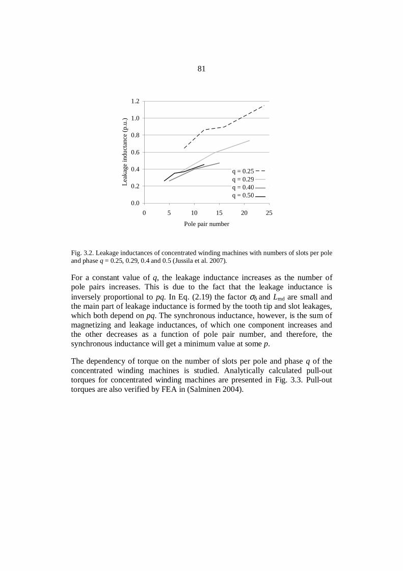
81
q = 0.25q = 0.29q = 0.40q = 0.50
0.0
0.2
0.4
0.6
0.8
1.0
1.2
0 5 10 15 20 25
Pole pair number
Leak
age
indu
ctan
ce (p
.u.)
Fig. 3.2. Leakage inductances of concentrated winding machines with numbers of slots per poleand phase q = 0.25, 0.29, 0.4 and 0.5 (Jussila et al. 2007).
For a constant value of q, the leakage inductance increases as the number ofpole pairs increases. This is due to the fact that the leakage inductance isinversely proportional to pq. In Eq. (2.19) the factor σδ and Lmd are small andthe main part of leakage inductance is formed by the tooth tip and slot leakages,which both depend on pq. The synchronous inductance, however, is the sum ofmagnetizing and leakage inductances, of which one component increases andthe other decreases as a function of pole pair number, and therefore, thesynchronous inductance will get a minimum value at some p.
The dependency of torque on the number of slots per pole and phase q of theconcentrated winding machines is studied. Analytically calculated pull-outtorques for concentrated winding machines are presented in Fig. 3.3. Pull-outtorques are also verified by FEA in (Salminen 2004).

82
q = 0.25q = 0.29q = 0.40q = 0.50
0.0
0.5
1.0
1.5
2.0
2.5
0 5 10 15 20 25
Pole pair number
Pull
out t
orqu
e (p
.u.)
Fig. 3.3. Pull-out torques of concentrated winding machines with q = 0.25, 0.29, 0.4 and 0.5(Jussila et al. 2007).
It can be seen that machines having q = 0.25 give the smallest pull-out torques.A higher torque was produced when q was increased (Salminen 2004, Salminenet al. 2005, Salminen et al. 2006, Jussila et al. 2007).
The inductances and torques of the integral slot winding machines werecompared with the values of concentrated winding machines. Semi-closed slotopenings are used. In Fig. 3.4, the magnetizing inductance Lmd and the leakageinductance L are calculated analytically for a concentrated winding (q = 0.5)and an integral slot winding machine (q = 2).

83
0.0
0.1
0.2
0.3
0.4
0.5
0.6
0.7
0.8
0.9
1.0
0 2 4 6 8 10 12 14
pole pair number
Indu
ctan
ce (p
.u.)
Synchronous inductanceMagnetizing inductanceLeakage inductance
a)
0.0
0.1
0.2
0.3
0.4
0.5
0.6
0.7
0.8
0.9
1.0
0 2 4 6 8 10 12 14
pole pair number
Indu
ctan
ce (p
.u.)
Synchronous inductanceMagnetizing inductanceLeakage inductance
b)
Fig. 3.4. a) Synchronous inductance Ld, magnetizing inductance Lmd and leakage inductance Lof a concentrated winding (q = 0.5) machine as a function of pole pair number. b)Corresponding values of integral slot winding (q = 2) machines as a function of pole pairnumber (Jussila et al. 2007)
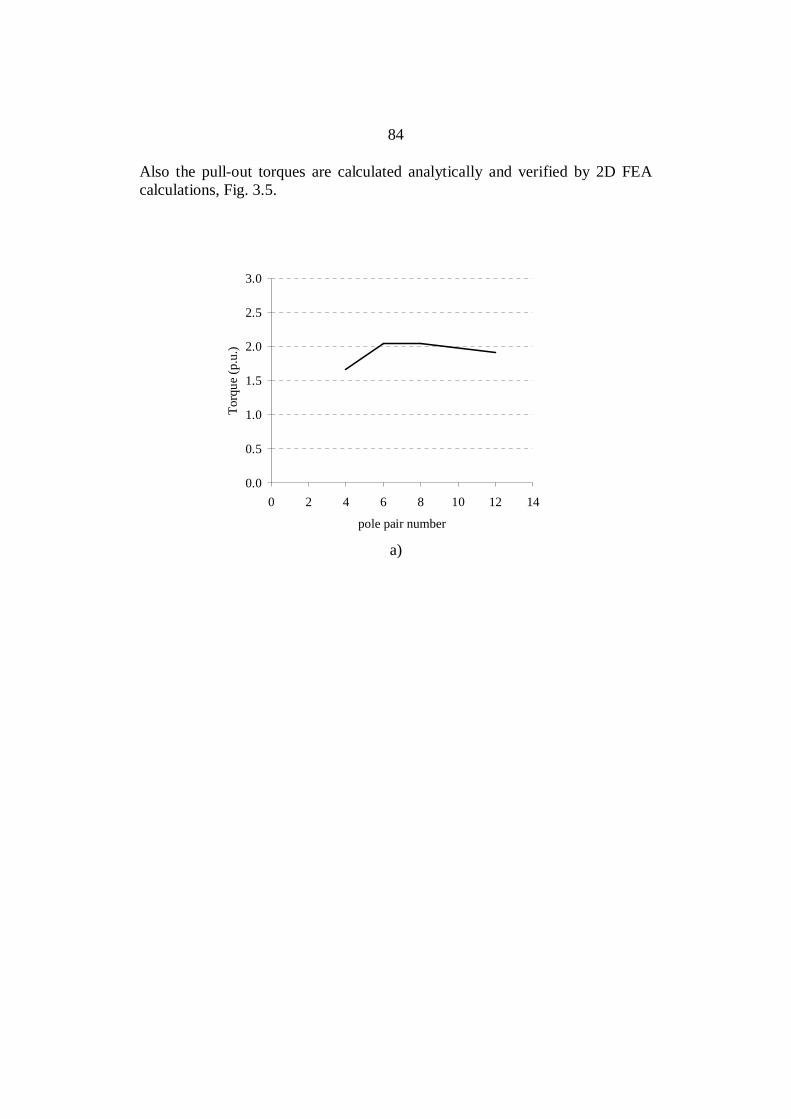
84
Also the pull-out torques are calculated analytically and verified by 2D FEAcalculations, Fig. 3.5.
0.0
0.5
1.0
1.5
2.0
2.5
3.0
0 2 4 6 8 10 12 14
pole pair number
Torq
ue (p
.u.)
a)
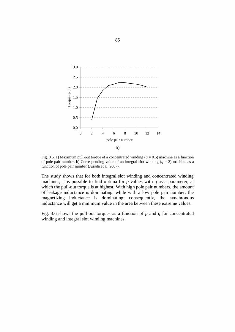
85
0.0
0.5
1.0
1.5
2.0
2.5
3.0
0 2 4 6 8 10 12 14
pole pair number
Torq
ue (p
.u.)
b)
Fig. 3.5. a) Maximum pull-out torque of a concentrated winding (q = 0.5) machine as a functionof pole pair number. b) Corresponding value of an integral slot winding (q = 2) machine as afunction of pole pair number (Jussila et al. 2007).
The study shows that for both integral slot winding and concentrated windingmachines, it is possible to find optima for p values with q as a parameter, atwhich the pull-out torque is at highest. With high pole pair numbers, the amountof leakage inductance is dominating, while with a low pole pair number, themagnetizing inductance is dominating; consequently, the synchronousinductance will get a minimum value in the area between these extreme values.
Fig. 3.6 shows the pull-out torques as a function of p and q for concentratedwinding and integral slot winding machines.

86
18 16 14 12 10 8 64
0.25 0.29 0.
4 0.5 1 2
0.0
0.5
1.0
1.5
2.0
2.5
Pull-out torque(p.u.)
Number of polepairs Number of slots per pole
and phase
0.25 0.29 0.4
0.5 1 2
Fig. 3.6. Pull-out torque as a function of p and q for concentrated winding and integral slotwinding PM machines.
When comparing integral slot winding machines and concentrated windingmachines, it is noticeable that the per unit inductances and pull-out torquesbehave quite similarly as a function of pole pair number. The minima andmaxima are located at about the same pole pair numbers. However, integral slotwinding machines produce more torque with the same rotor size.
A small synchronous inductance is necessary to obtain a high torque from thepermanent magnet motor. The maximum torque is inversely proportional to thesynchronous inductance (Tmax ≅ Ld
-1). The results show that as q increases from0.25 to 0.5, the pull-out torque of the concentrated winding machine increases.However, as q increases further and integral slot windings (q = 1, q = 2) areused, the torque development will be higher when the same rotor maindimensions are maintained. This indicates that selecting a concentrated windingconstruction must have other relevant reasons than maximizing the rotor torqueper rotor volume ratio.
It is possible to take an advantage of the short end windings of concentratedwindings by inserting a longer stator stack compared with the stack of integerslot wound machines in the same frame size. Consequently, longer active partswill give more torque (Cros and Viarouge 2004, Salminen 2004, Libert andSoulard 2004). Concentrated winding machines also provide an opportunity ofusing a large number of poles, which leads to a low stator yoke thickness, hence
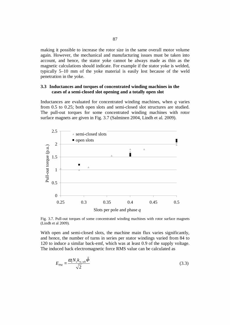
87
making it possible to increase the rotor size in the same overall motor volumeagain. However, the mechanical and manufacturing issues must be taken intoaccount, and hence, the stator yoke cannot be always made as thin as themagnetic calculations should indicate. For example if the stator yoke is welded,typically 5–10 mm of the yoke material is easily lost because of the weldpenetration in the yoke.
3.3 Inductances and torques of concentrated winding machines in thecases of a semi-closed slot opening and a totally open slot
Inductances are evaluated for concentrated winding machines, when q variesfrom 0.5 to 0.25; both open slots and semi-closed slot structures are studied.The pull-out torques for some concentrated winding machines with rotorsurface magnets are given in Fig. 3.7 (Salminen 2004, Lindh et al. 2009).
0
0.5
1
1.5
2
2.5
0.25 0.3 0.35 0.4 0.45 0.5
Slots per pole and phase q
Pull-
out t
orqu
e (p
.u.)
semi-closed slotsopen slots
Fig. 3.7. Pull-out torques of some concentrated winding machines with rotor surface magnets(Lindh et al 2009).
With open and semi-closed slots, the machine main flux varies significantly,and hence, the number of turns in series per stator windings varied from 84 to120 to induce a similar back-emf, which was at least 0.9 of the supply voltage.The induced back electromagnetic force RMS value can be calculated as
2
ˆwh,wss
PMkN
Eω
= (3.3)

88
where ω is the electric angular frequency, Ns the number of turns in series perstator winding, kw,wh the fundamental or working harmonic winding factor andΦ the peak value of the flux passing through the magnetic pole.
Machines with open slot structures must have more winding turns comparedwith machines with semi-closed slot structures to produce the same back-emf.This is because the amount of flux that can flow through the air gap to the statorteeth is higher in the semi-closed structure. In an open slot structure there arenarrow teeth facing the air gap, and therefore, the area through which the fluxcan flow is smaller. Figure 3.8 illustrates the effect of semi-closed and openslots.
a) b)
Fig. 3.8. 36-slot-24-pole motor, which has a) semi-closed slot openings with the relative slotopening width of 0.09 of the slot pitch and b) open slots with relative slot opening width of 0.6of the slot pitch (Lindh et al. “Concentrated Wound PM Motors with Semiclosed Slots and withOpen Slots.”IEEE Energy Conversion (forthcoming)).
In (Lindh et al. 2009) it was observed that with semi-closed slots theefficiencies of different machines were slightly better. This is, of course a resultof the main flux variation and the change of the number of turns.
3.4 Summary
Concentrated winding permanent magnet machines with rotor surface magnetsgive a high torque, when the number of slots per pole and phase q is chosen tobe either 0.4 or 0.5. The concentrated winding machines with q = 0.5 producethe highest pull-out torque values. However, using this number of slots per poleand phase (q = 0.5) leads to high sensitivity in selecting the machinedimensions because the torque quality of the machine is strongly dependent oncorrect mechanical dimensions (Salminen 2004, Salminen et al. 2006).Furthermore, very high torque ripples and cogging torques easily occur in a q =

89
0.5 machine (Salminen 2004, Salminen et al. 2006). In most studied cases, theconcentrated winding machines give a lower pull-out torque than integral slotwinding machines with the same rotor dimensions. However, concentratedwinding machines provide some benefits such as small copper losses and smallend windings in certain applications.
Rotor surface magnet motors with open slot structures give slightly higher pull-out torques, but the efficiencies of the open slot structures remain somewhatlower than in motors with semi-closed slots. This is mainly due the higher statorJoule losses. An attractive solution would be to manufacture machines withtotally open slots to have the simplest possible stator structure, which of coursealso provides a means to reduce production costs. Open slot machines can bewound automatically.
According to the previous study, the 12-slot-10-pole concentrated windingmachine is one of the best alternatives when concentrated winding machines, ingeneral, are desired. Its torque producing capability is almost as good as with q= 0.5 machines (Salminen 2004) and not very much lower than in integral slotwinding machines. As the winding arrangement provides an opportunity toincrease the rotor size in a certain overall size compared with integral slotwinding machine rotors, it seems that the 12-10-machine is a good compromiseamong concentrated winding machines with q ≤ 0.5.
In the following chapter, a new 12-10-axial-flux PMSM construction isintroduced for normal industrial speeds. The basic construction was selectedbecause its manufacturing costs are low compared with integral slot windingmachines and because it is easy to integrate such a short machine into aworking machine construction such as a fan or a compressor. Such machinesoperate at normal industrial speeds from 1500 to 6000 min-1. In this speedrange, a special problem with concentrated winding and open slot machines isthe heavy permeance-harmonics-caused eddy current loss in the permanentmagnets, and therefore special effort has been put to find a solution to solve themagnet heating problem in the design.
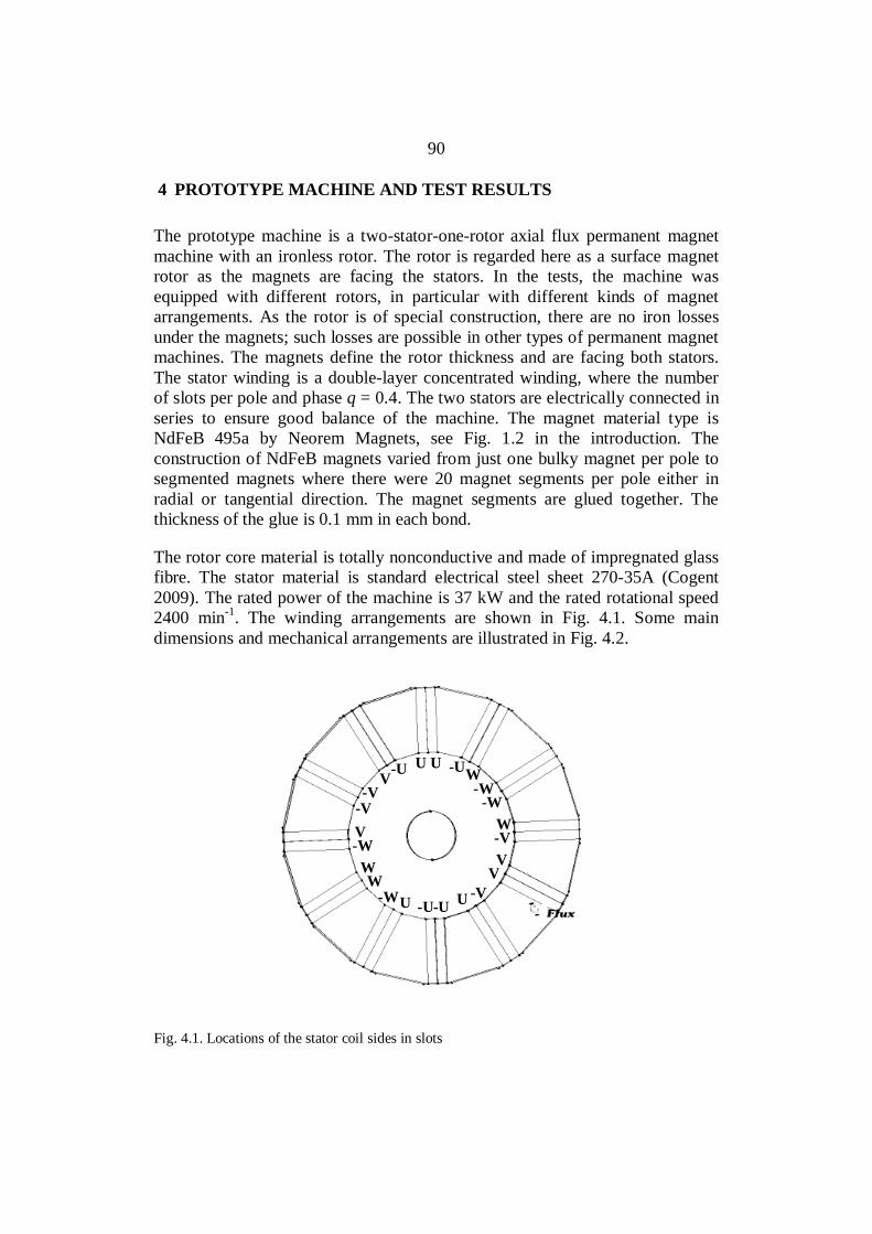
90
4 PROTOTYPE MACHINE AND TEST RESULTS
The prototype machine is a two-stator-one-rotor axial flux permanent magnetmachine with an ironless rotor. The rotor is regarded here as a surface magnetrotor as the magnets are facing the stators. In the tests, the machine wasequipped with different rotors, in particular with different kinds of magnetarrangements. As the rotor is of special construction, there are no iron lossesunder the magnets; such losses are possible in other types of permanent magnetmachines. The magnets define the rotor thickness and are facing both stators.The stator winding is a double-layer concentrated winding, where the numberof slots per pole and phase q = 0.4. The two stators are electrically connected inseries to ensure good balance of the machine. The magnet material type isNdFeB 495a by Neorem Magnets, see Fig. 1.2 in the introduction. Theconstruction of NdFeB magnets varied from just one bulky magnet per pole tosegmented magnets where there were 20 magnet segments per pole either inradial or tangential direction. The magnet segments are glued together. Thethickness of the glue is 0.1 mm in each bond.
The rotor core material is totally nonconductive and made of impregnated glassfibre. The stator material is standard electrical steel sheet 270-35A (Cogent2009). The rated power of the machine is 37 kW and the rated rotational speed2400 min-1. The winding arrangements are shown in Fig. 4.1. Some maindimensions and mechanical arrangements are illustrated in Fig. 4.2.
U
U U-U -U
-U
V
-W
-WV
V
W
W
WW
-V
-V
-V-UU
V-V -W
-W
Fig. 4.1. Locations of the stator coil sides in slots

91
a) Rotor arrangement b) 3D sketch of one motor half
c) Magnet versions, slicing directions
26 mm
18 mm
54 mm
5.5 mm
2 mm2 mm
d) Stator slot dimensions
Fig. 4.2. Main dimensions and mechanical arrangements.
Figure 4.3 illustrates the mesh used in the FEA calculations and the time stepsapplied in the 2D and 3D FEA; 6.94 s in 2D and 34.7 s in 3D.
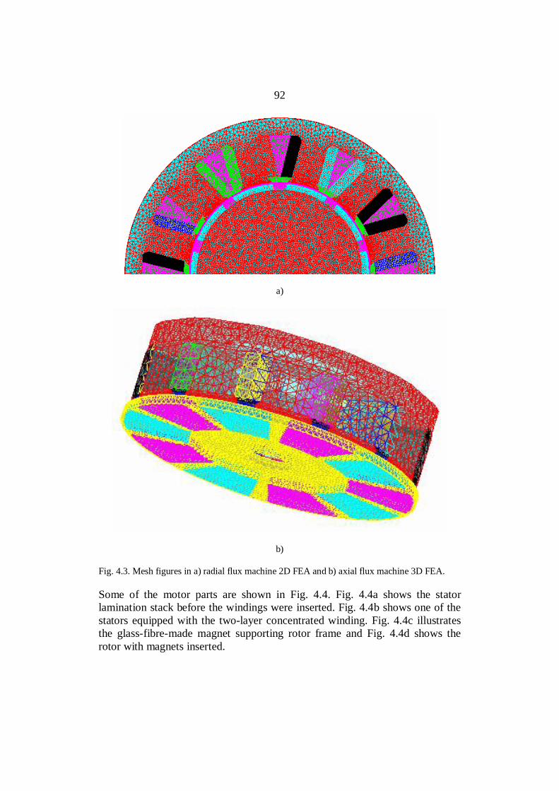
92
a)
b)
Fig. 4.3. Mesh figures in a) radial flux machine 2D FEA and b) axial flux machine 3D FEA.
Some of the motor parts are shown in Fig. 4.4. Fig. 4.4a shows the statorlamination stack before the windings were inserted. Fig. 4.4b shows one of thestators equipped with the two-layer concentrated winding. Fig. 4.4c illustratesthe glass-fibre-made magnet supporting rotor frame and Fig. 4.4d shows therotor with magnets inserted.

93
a) b)
c) d)
Fig. 4.4. a) Stator lamination stack, b) one stator equipped with windings, c) rotor frame, d)rotor with magnets assembled
As it can be seen in Fig. 4.4a, the stator lamination is not ideal as the teeth donot bend but all the bending takes place in the stator yoke adjacent to the slotarea. This causes a radius variation to the stator lamination, which may causeslight extra losses in the motor.

94
The main parameters of the machine are listed in Table 4.1.
Table 4.1. Main parameters of the prototype machines.
Number of stator slots, Q 12
Number of rotor poles, 2p 10Winding factor of the fifth harmonic of the stator(the machine operates with the fifth harmonic), kw5
0.933
Output power, Pout 37 kW
Speed, ns 2400 min-1
Line-to-line terminal voltage in star connection, U 400 V
Winding turns in series per stator winding, Ns 64
Rated torque, TN 147 Nm
Rated current, Is 59–61 A
Length of air gap (on both sides of the rotor) 2.0 mm
External diameter of the stator stack, Do, axial 274 mm
Internal diameter of the stator stack, Di, axial 154 mmStator yoke height, hys 21 mm
Thickness of PM, hPM 16 mm
PM remanent flux density, 20 ºC, Br20C 1.1 T
PM remanent flux density, 80 ºC, Br80C 1.03T
Mass of magnets (NdFeB), mPM 3.9 kg
PM resistivity ρPM 150 µ cm
The machine is totally enclosed and fan cooled. Fig. 4.5 illustrates the motorwithout and with a fan. The fan motor input power is 350 W.

95
a) b)
Fig. 4.5. Motor without a fan and with an externally operated fan.
In the measurements, the prototype motor was fed by a variable-speedfrequency converter (ABB M1 DTC converter) and rotated or loaded with adirect current (DC) machine drive. The torque of the motor was measured withtwo different torque transducers; in the load tests, the rated torque of the torquetransducer was 200 Nm, and when the rotor mechanical loss and the permanentmagnet losses were measured in the DC motor drive, the torque transducer ratedtorque was selected to be 50 Nm in order to obtain more accurate results for therotor mechanical loss. The electrical values of the PM machine drive weremeasured with a Yogokawa PZ4000 power analyzer. Table 4.2 shows themeasurement devices and their uncertainties, and Fig. 4.6 illustrates the testsetup.
Table 4.2. Measurement devices and their accuracies.
Measurement device
Measurementuncertainty (%of the ratedvalue)
Torque transducer: Vibrometer, Torquemaster TM-214 0.2Torque transducer: Vibrometer, Torquemaster TM-204 0.2Reading unit for torque transducer: Vibrometer, DCU 280 0.1Power analyzer: Yokogawa PZ4000 0.1Current transducers 0.2Reading unit for the temperature values: Fluke Hydra2620A 0.1
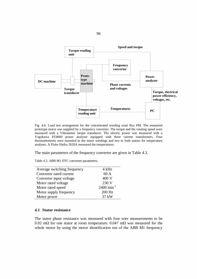
96
Torque readingunit
Frequencyconverter
Poweranalyzer
PCTemperaturereading unit
DC machine
Torquetransducer
Proto-typemachine
Speed and torque
Phase currentsand voltages
Temperatures
Torque, electricalpower efficiency,voltages, etc.
Fig. 4.6. Load test arrangement for the concentrated winding axial flux PM. The measuredprototype motor was supplied by a frequency converter. The torque and the rotating speed weremeasured with a Vibrometer torque transducer. The electric power was measured with aYogokawa PZ4000 power analyzer equipped with three current transformers. Fourthermoelements were mounted in the stator windings and two in both stators for temperatureanalyses. A Fluke Hydra 2620A measured the temperatures.
The main parameters of the frequency converter are given in Table 4.3.
Table 4.3. ABB M1 DTC converter parameters.
Average switching frequency 4 kHzConverter rated current 60 AConverter input voltage 400 VMotor rated voltage 230 VMotor rated speed 2400 min-1
Motor supply frequency 200 HzMotor power 37 kW
4.1 Stator resistance
The stator phase resistance was measured with four wire measurements to be0.02 m for one stator at room temperature. 0.047 m was measured for thewhole motor by using the motor identification run of the ABB M1 frequency

97
converter. The motor cabling was taken into account in the measurement resultsby the frequency converter.
No-load measurements
The no-load tests were performed in the generator mode using the DC machinedrive as a prime mover. The no-load test was performed to evaluate the inducedback-emf, stator iron losses, the Joule losses of the permanent magnets and themechanical loss in no-load conditions. The measured no-load voltages of themachine are given in Table 4.4.
Table 4.4. Measured and calculated FEA 2D/3D voltages at no load at 2400 min-1 in thegenerator mode.
Rotor equipped with MeasuredEPM (V)
2D FEAEPM (V)
3D FEAEPM (V)
radially segmented magnets 220 222 -tangentially segmented magnets 227 - -bulky magnets 220 229 225
The analysis of the voltages given in Table 4.4 is presented in Figs. 4.7 and 4.8.A comparison of no-load voltage waveform between the measurements and thecomputation results are given in Fig. 4.7, whereas Fig. 4.8 illustrates the effectof segmentation. The figure shows a slight voltage drop, which is proportionalto reduction in the magnet volume caused by the glue bonds between thesegments.

98
-400
-300
-200
-100
0
100
200
300
400
0.000 0.001 0.002 0.003 0.004 0.005
Time (s)
Indu
ced
volta
ge (V
)3D FEAMeasurement
Fig. 4.7. Voltage with the 3D FEA and the measurement. The no-load voltage waveform wasmeasured for the motor equipped with bulky magnets, and it corresponded well with the voltagecomputed by the 3D FEA.
-200
-150
-100
-50
0
50
100
150
200
0.0150 0.0170 0.0190 0.0210
Time (s)
Indu
ced
Vol
tage
(V)
2D FEA, bulky magnets
2D FEA, segmented magnets
Fig. 4.8. Effect of segmentation. The voltage drop is proportional to the change in volume of themagnet mass when segmented magnets (20) are used. Half of the axial flux machine (one stator)is modelled to the radial flux machine.

99
One of the most important and interesting results is related to the losses of thepermanent magnets. To find the permanent magnet losses, the no-loadmechanical loss of the rotor was first measured without magnets. Thepermanent magnet slot openings were covered during the test to ensure asmooth rotor surface. The loss was measured by using a 50 Nm torque gauge,and the result may be considered reliable. The no-load mechanical loss of themachine was measured to be 170 W. The measured no-load losses of themachine are given in Table 4.5.
Table 4.5. Measured losses at no load at 2400 min-1 in the generator mode compared with the2D FEA results.
Rotor equipped with Measured losses (W)2D FEA losses (W) +measured mechanical
losses (170 W)
radially segmented magnets 630 630
tangentially segmented magnets 680 - (not possible tocalculate with 2 D)
bulky magnets 2000 2400Rotor frame (no magnets) 170 -
There are also some differences in the measurements of the motor equippedwith rotors having either radially or tangentially segmented magnets. This ismainly because there were some difficulties in achieving exactly the same airgap lengths in all cases. There was also a voltage drop in the actualmeasurement, which may partly explain the smaller loss in the case of bulkymagnets. The measured loss was smaller than the loss evaluated by the 2DFEA.
To find out the losses in the permanent magnets, the stator no-load iron lossesshould be known. As the motor flux cannot be varied, definition of the ironlosses is difficult. Hence, FEA calculations are used to facilitate the definitionof the iron losses at no load. According to the finite element analysis, the ironlosses in the stator should be 370 W at EPM = 229 V. With segmented magnets,the iron losses in the stator were calculated to be 350 W at EPM = 222 V. Thecorresponding losses in the bulky magnets were calculated to be 1900 W, and inthe segmented magnets 110 W. Table 4.6 gives an estimation of the lossdivision at no load.
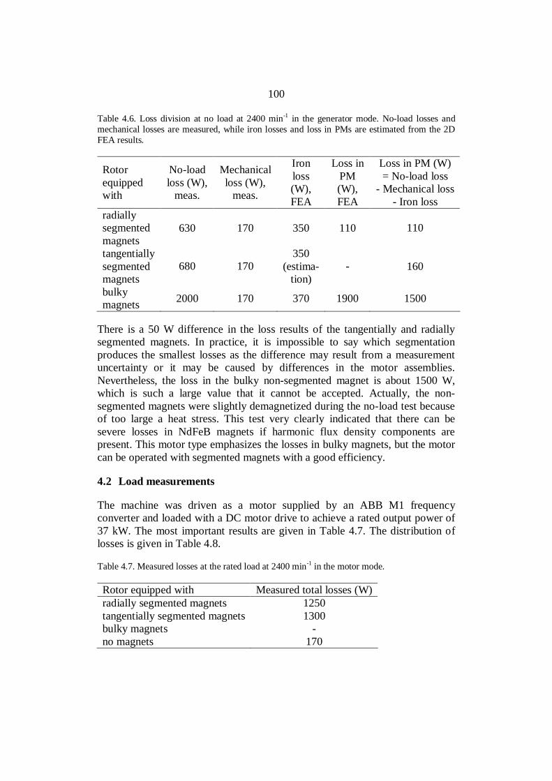
100
Table 4.6. Loss division at no load at 2400 min-1 in the generator mode. No-load losses andmechanical losses are measured, while iron losses and loss in PMs are estimated from the 2DFEA results.
Rotorequippedwith
No-loadloss (W),
meas.
Mechanicalloss (W),
meas.
Ironloss(W),FEA
Loss inPM(W),FEA
Loss in PM (W)= No-load loss
- Mechanical loss- Iron loss
radiallysegmentedmagnets
630 170 350 110 110
tangentiallysegmentedmagnets
680 170350
(estima-tion)
- 160
bulkymagnets 2000 170 370 1900 1500
There is a 50 W difference in the loss results of the tangentially and radiallysegmented magnets. In practice, it is impossible to say which segmentationproduces the smallest losses as the difference may result from a measurementuncertainty or it may be caused by differences in the motor assemblies.Nevertheless, the loss in the bulky non-segmented magnet is about 1500 W,which is such a large value that it cannot be accepted. Actually, the non-segmented magnets were slightly demagnetized during the no-load test becauseof too large a heat stress. This test very clearly indicated that there can besevere losses in NdFeB magnets if harmonic flux density components arepresent. This motor type emphasizes the losses in bulky magnets, but the motorcan be operated with segmented magnets with a good efficiency.
4.2 Load measurements
The machine was driven as a motor supplied by an ABB M1 frequencyconverter and loaded with a DC motor drive to achieve a rated output power of37 kW. The most important results are given in Table 4.7. The distribution oflosses is given in Table 4.8.
Table 4.7. Measured losses at the rated load at 2400 min-1 in the motor mode.
Rotor equipped with Measured total losses (W)radially segmented magnets 1250tangentially segmented magnets 1300bulky magnets -no magnets 170

101
Table 4.8. Loss distribution at load at 2400 min-1 in the motor mode. The load losses andmechanical losses are measured, while the iron losses, copper losses and loss in the PMs areestimated from the 2D FEA results.
Rotorequippedwith
Loadloss(W),meas.
Mecha-nicalloss(W),meas.
Iron loss(W),FEA
Copperloss(W),calc.
Lossin
PM(W),FEA
Loss in PM(W) (+
additional loss(W))
= Load loss- Mechanical
loss- Iron loss
- Copper lossradiallysegmentedmagnets
1250 170 330 560 100 190
tangentiallysegmentedmagnets
1300 170 330(estimation) 560 - 240
The efficiency of the prototype motor with both segmented magnets at the ratedload was measured to be between 0.96–0.97. The measured efficiencies withtwo different rotational speeds are shown in Fig. 4.9.
0.900.910.920.930.940.950.960.970.98
0 10 20 30 40
Output power (kW)
Effic
ienc
y
radially segmented,2400 rpm
a)

102
0.900.910.920.930.940.950.960.970.98
0 10 20 30 40
Output power (kW)
Effic
ienc
y
radially segmented,2000 rpm
b)
0.900.910.920.930.940.950.960.970.98
0 10 20 30 40
Output power (kW)
Effic
ienc
y
tangentially segmented,2400 rpm
c)
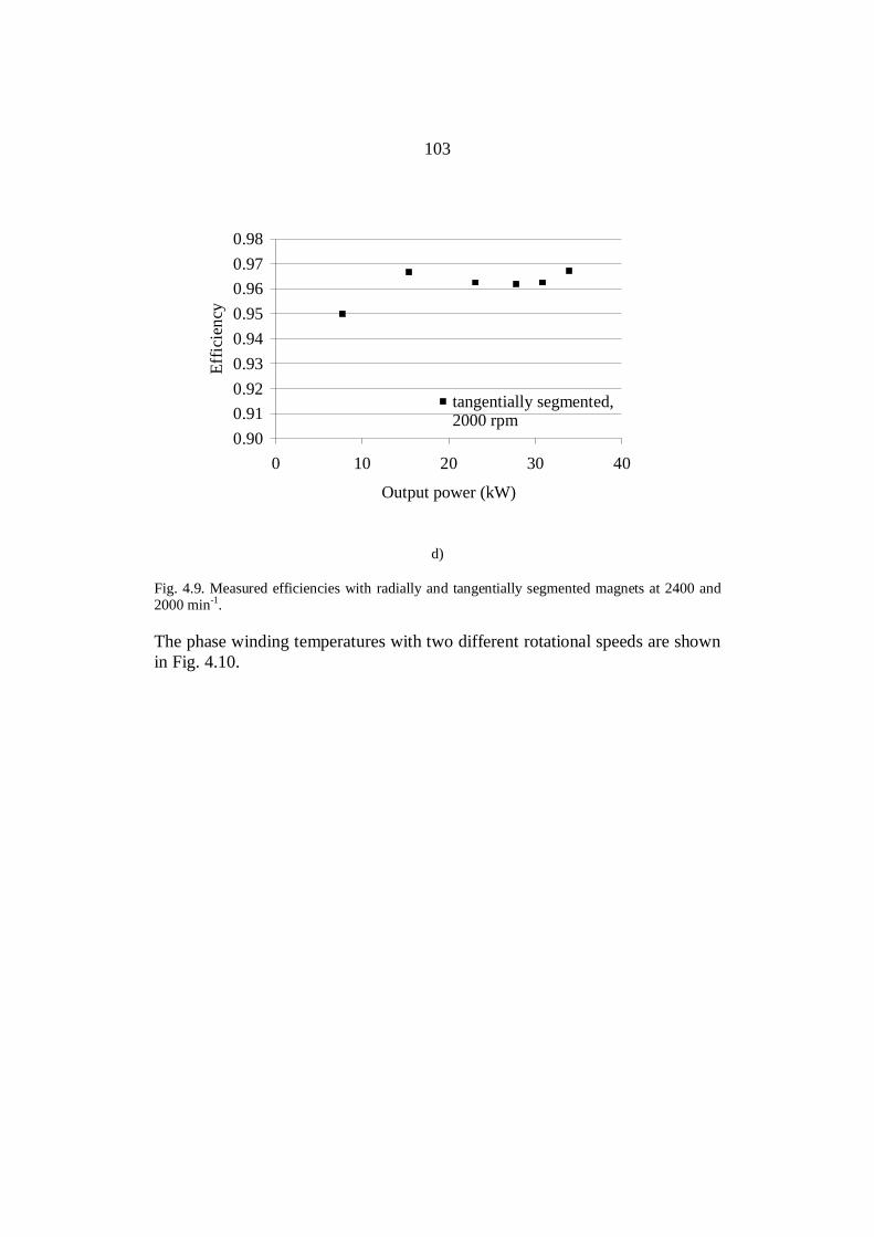
103
0.900.910.920.930.940.950.960.970.98
0 10 20 30 40
Output power (kW)
Effic
ienc
y
tangentially segmented,2000 rpm
d)
Fig. 4.9. Measured efficiencies with radially and tangentially segmented magnets at 2400 and2000 min-1.
The phase winding temperatures with two different rotational speeds are shownin Fig. 4.10.

104
0
20
40
60
80
100
120
0 20 40 60 80 100Time (min)
T (o C
)
Outer end-winding at N-endInner end-winding at D-endSlot centreSlot centreFull load
a)
0
20
40
60
80
100
120
0 20 40 60 80 100Time (min)
T (o C
)
Outer end-winding at N-endInner end-winding at D-endSlot centreSlot centreFull load
b)
Fig. 4.10. Temperatures at rated loads. a) Radially segmented and b) tangentially segmentedmagnets at 2400 min-1.
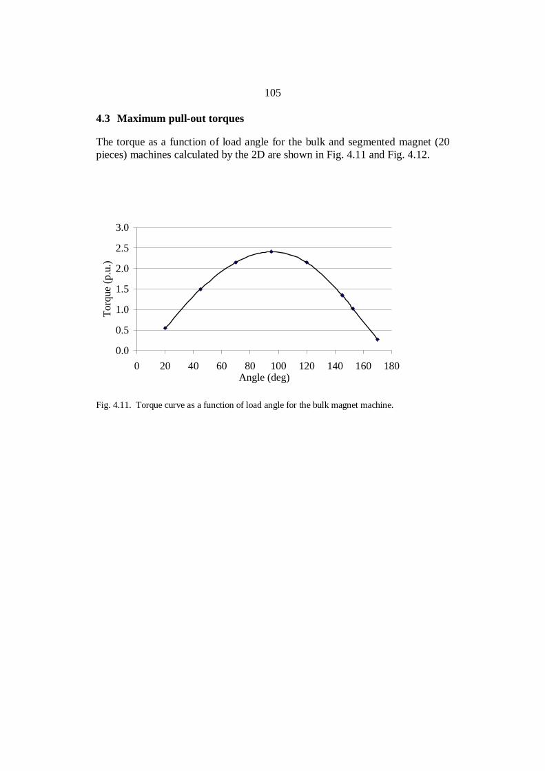
105
4.3 Maximum pull-out torques
The torque as a function of load angle for the bulk and segmented magnet (20pieces) machines calculated by the 2D are shown in Fig. 4.11 and Fig. 4.12.
0.0
0.5
1.0
1.5
2.0
2.5
3.0
0 20 40 60 80 100 120 140 160 180Angle (deg)
Torq
ue (p
.u.)
Fig. 4.11. Torque curve as a function of load angle for the bulk magnet machine.
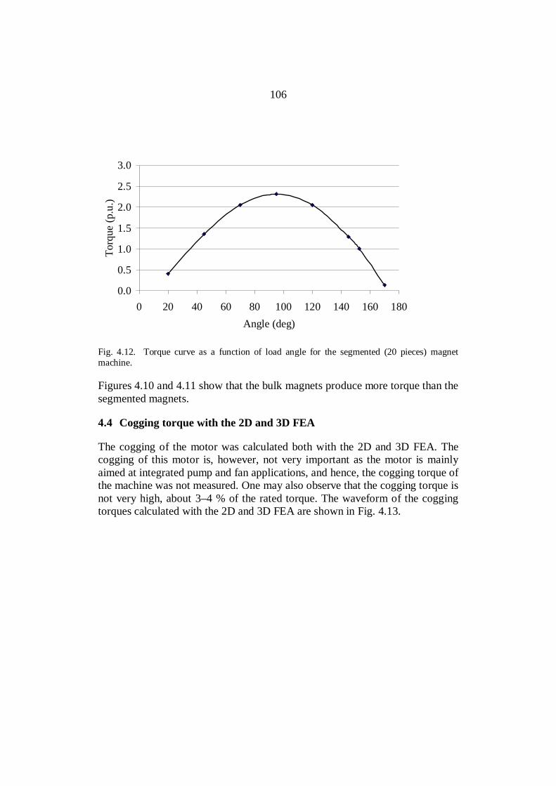
106
0.0
0.5
1.0
1.5
2.0
2.5
3.0
0 20 40 60 80 100 120 140 160 180Angle (deg)
Torq
ue (p
.u.)
Fig. 4.12. Torque curve as a function of load angle for the segmented (20 pieces) magnetmachine.
Figures 4.10 and 4.11 show that the bulk magnets produce more torque than thesegmented magnets.
4.4 Cogging torque with the 2D and 3D FEA
The cogging of the motor was calculated both with the 2D and 3D FEA. Thecogging of this motor is, however, not very important as the motor is mainlyaimed at integrated pump and fan applications, and hence, the cogging torque ofthe machine was not measured. One may also observe that the cogging torque isnot very high, about 3–4 % of the rated torque. The waveform of the coggingtorques calculated with the 2D and 3D FEA are shown in Fig. 4.13.

107
-5
-4
-3
-2
-1
0
1
2
3
4
5
10 20 30 40 50 60
Mechanical angle (deg)
Cog
ging
torq
ue %
of r
ated
torq
ue
3D FEA2D FEA
Fig. 4.13. Peak-to-peak values of the cogging torque in (%) of the rated torque with the 2D and3D FEA.
4.5 Summary
A 37 kW axial flux machine was designed and constructed. A comparisonbetween the theoretical and experimental results with the prototype machinewas presented. The analytical, 2D and 3D FEA values together with themeasured values show a good agreement.

108
5 CONCLUSION
The work focused on the properties of concentrated winding multiphasepermanent magnet machines. Such machines have their benefits and drawbacks;however, their analytical calculation and also the 2D FEA-based analysis willpose some challenges. The 3D FEA is a good design tool, yet too timeconsuming for practical applications at the moment.
The benefits of the machine type may be regarded as:
• Extremely compact design.
• Low amount of copper needed as the end windings are very shortcompared with traditional integral slot winding machines.
• Small stator and rotor yokes needed as pole numbers are high.
• Large rotor volume, and hence, large torque per predetermined outerdimensions.
• Suitable construction for, especially, large-torque low-speedapplications.
• Good torque quality when properly designed.
• Low manufacturing costs because prefabricated windings can be used,especially, in open slot constructions.
The main drawbacks of the machine type are:
• Difficult to design applying traditional analytical methods.
• High permanent magnet losses as the flux density in the permanentmagnets fluctuates heavily because there is no smooth stator surface, butbetween each tooth there can be large spaces of air that make thepermanent magnet material flux density vary considerably causing highlosses in sintered materials.
• At higher speeds, more expensive segmented permanent magnets areneeded to avoid large Joule losses in the magnets.
In the work, concentrated winding multiphase machines were analyzednumerically by Cedrat’s Flux2D/3D version 10.2.4. and by measurements. One
109
of the objectives of this study was to study the effect of permanent magnetsegmentation in a concentrated winding multiphase axial flux machine. Also theeffect of the segmentation directions on the motor performance and the PMJoule losses were studied experimentally.
The scientific contributions of this thesis can be listed as:
1. A set of analytic equations and methods were found to design a 12-slot10-pole axial-flux machine with rotor-surface-mounted magnets.
2. The correct effective length of a PMSM with rotor surface magnets wasdetermined.
3. Stator leakage inductance, especially air gap leakage inductancecalculation was clarified.
4. The torque production capabilities of concentrated winding and integralslot winding machines were compared.
5. The permanent magnet Joule losses in an axial flux PMSM with openslots operating at a typical industrial machine speed were evaluated.
6. A new practical permanent magnet motor type for industrial use wasintroduced.
After having built a prototype with several different rotor constructions, theinduced back-emfs of the three different rotor constructions were measured atno load. The analytical results, Cedrat’s Flux2D/3D results and the measuredresults of the no-load voltage were compared. There was quite a goodcorrespondence between the measured, 2D and analytical results of thesegmented magnets.
One of the rotors was equipped with bulky permanent magnets. It becameobvious already in the no-load tests that bulky magnets cannot be used in thesekinds of machines because of excessive Joule losses in the magnets.
The efficiencies of the three different rotor constructions were measured in no-load and load tests. The permanent magnet losses at no load were separated bymeasuring the friction losses without permanent magnets in the rotor andcalculating the stator Joule losses by Cedrat’s Flux2D/3D. At load also thestator copper losses are taken into account. Of course, there occurred also someinverter-caused time-harmonic-based losses in the measurements; however,these losses were not studied in detail in the thesis.
5.1 Future Work
In the analytic calculation of Joule losses, a considerable uncertainty stillremains, and hence, the calculation methods should be further developed.Optimization of the magnet width and the slot opening width to reduce cogging

110
in the proposed motor design should be carried out. The Joule losses in themagnets could maybe be further reduced by suitable means, for instance, byusing semi-magnetic slot wedges. Moreover, the mechanical construction of theironless rotor should be further developed to reach higher speeds and a morerigid rotor construction as a whole.
111
REFERENCES
ABB, 2007. Product catalogue : IEC Low Voltage Induction Motors 400 V 50Hz. [Online]. Available from http://www.abb.com/ [Accessed 5 October 2009].
Amara, Y., Jiabin W. and Howe, D. 2005. “Analytical Prediction of Eddy-Current Loss in Modular Tubular Permanent-Magnet Machines.” IEEETransactions on Energy Conversion. Vol. 20, Issue 4, pp. 761–770.
Arrillaga, J. and Watson, N.R. 2003. Power System Harmonics. Chichester:John Wiley & Sons, Ltd.
Atallah, K., Howe, D., Mellor, P.H. and Stone, D.A. 2000. “Rotor Loss inPermanent Magnet Brushless AC Machines.” IEEE Transactions on IndustryApplications. Vol. 36, Issue 6, pp. 1612–1618.
Baracat, G., El-Meslouhi, T. and Dakyo, B. 2001. “Analysis of the CoggingTorque Behavior of a Two-Phase Axial-flux Permanent Magnet SynchronousMachine.”IEEE Transactions on Magnetics. Vol. 37, Issue 4, pp. 2803–2805.
Bertotti, G., Boglietti, A., Chiampi, M., Chiarabaglio, D., Fiorillo F. andLazzari, M. 1991. “An Improved estimation of Iron Losses in ElectricalMachines.”IEEE Transactions on Magnetics. Vol. 27, Issue 6, pp. 5007–5009.
Cedrat, 2009. Software solutions: Flux®. [Online]. Available fromhttp://www.cedrat.com/ [Accessed 2 April 2009].
Cistelecan, M.V. and Popescu, M. 2007. “Study of the Number of Slots/PoleCombinations for Low Speed Permanent Magnet Synchronous Generators.” InProceedings Electric Machines & Drives Conference, IEMDC 2007. Vol. 2, pp.1616–1620.
Cogent, 2009. Product catalogue: Non-oriented Fully Processed ElectricalSteels. [Online]. Available from http://www.sura.se/ [Accessed 5 October2009].
Cros, J., Viarouge, P. 2002. “Synthesis of High Performance PM Motors WithConcentrated Windings.”IEEE Transactions on Energy Conversion. Vol. 17,Issue 2, pp. 248–253.
Cros J., Viarouge, P., Carlson, R. and Dokonal, L.V. 2004. “Comparison ofbrushless DC motors with concentrated windings and segmented stator.” InProceedings of the International Conference on Electrical Machines, ICEM2004. Krakow, Poland. CD.

112
Deak, C., Binder, A. and Magyari, K. 2006. “Magnet Loss Analysis ofPermanent Magnet Synchronous Motors with Concentrated Windings.” InProceedings of the XVII International Conference on Electrical Machines,ICEM 2006. Chania, Crete Island, Greece. CD.
Deak, C., Petrovic, L., Binder, A., Mirzaei, M., Irimie, D. and Funieru, B. 2008.“Calculation of Eddy Current Losses in Permanent Magnets of SynchronousMachines.” In Proceedings of the International Symposium on PowerElectronics, Electrical Drives, Automation and Motion, SPEEDAM 2008.Ischia, Italy.
Deng, F. 1999. “An Improved Iron Loss estimation for Permanent MagnetBrushless Machines.” IEEE Transactions on Energy Conversion. Vol. 14, Issue4, pp. 1391–1395.
Dupas, F. and Espanet, C. 2009. “Analytical Solution of the Magnetic Field inPermanent-Magnet Motors Taking Into Account Slotting Effect: No-LoadVector Potential and Flux Density Calculation.” IEEE Transactions onMagnetics. Vol. 45, Issue 5, pp. 2097–2109.
Ede, J.D., Atallah K. and Jewell, G.W. 2007. “Effect of axial segmentation ofpermanent magnets on rotor loss in modular permanent-magnet brushlessmachines.”IEEE Transactions on Industry Applications. Vol. 43, Issue 5, pp.1207–1213.
Ede J.D., Atallah, K., Jewell G.W., Wang J. and Howe, D. 2002. “Effect ofAxial Segmentation of Permanent Magnets on Rotor Loss in ModularPermanent-Magnet Brushless Machines.” In Proceedings of the IEEInternational Conference on Power Electronics, Machines and Drives, PEMD2002. University of Bath, the UK, pp. 445–420.
El-Refaie, A.M. and Jahns, T.M. 2006. “Scalability of surface PM Machineswith concentrated windings designed to achieve wide speed ranges of constantpower operation.”IEEE Transactions on Energy Conversion. Vol. 21, Issue 2,pp. 362–369.
El-Refaie, A.M. and Jahns, T.M. 2007. “Comparison of synchronous PMmachine types for wide constant-power speed operation: converterperformance.” IET Electric Power Applications. Vol. 1, Issue 2, pp. 217–222.
El-Rafaie, A.M. and Jahns, T.M. 2008. “Impact of Winding Layer Number andMagnet Type on Synchronous Surface PM Machines Designed for WideConstant-Power Speed Range Operation.” IEEE Transactions on EnergyConversion. Vol. 23, Issue 1, pp. 53–60.

113
El-Refaie, A.M., Jahns, T.M., McCleer, P.J. and McKeever, J.W. 2006.“Experimental verification of optimal flux weakening in surface PM Machinesusing concentrated windings.” IEEE Transactions on Industry Applications.Vol. 42, Issue 2, pp. 443–453.
Gieras, F., Wang, R. and Kamper, M. 2008. Axial Flux Permanent MagnetMachines. Second edition. Dordrecht: Springer Science + Business Media B.V.
Gieras, J.F., Wang, C. and Lai, J.C. 2006. Noise of Polyphase Electric Motors.Taylor & Francis Group, LLC.
Gieras, F. and Wing, M. 1997. Permanent Magnet Motor Technology – Designand Applications. New York: Marcel Dekker, Inc.
Hanselman, D. 2003. Brushless Permanent Magnet Design. Second edition.Cranston, Rhode Island: The Writers’ collective.
Heikkilä, Tanja. 2002. Permanent magnet synchronous motor for industrialinverter applications - analysis and design. D.Sc. (Tech) dissertation. ActaUniversitatis Lappeenrantaensis 134. Lappeenranta, Finland.
Heller, B. and Hamata, V. 1977. Harmonic Field Effects in Induction Machines.Amsterdam: Elsevier Scientific Publishing Company.
Hendershot, J.R. Jr and Miller, T.J.E. 1994. Design of Brushless Permanent-Magnet Motors. Oxford: Magna physics publishing and Clarendon press.
International Magnetics Association, 2000. MMPA standard No 0100-00.[Online]. Available from: 5Hhttp://www.intl-magnetics.org/pdfs/0100-00.pdf[Accessed 27 June 2009].
Ishak, D., Zhu, Z.Q. and Howe, D. 2004. “Permanent Magnet BrushlessMachines with Unequal Tooth Widths and Similar Slot and Pole Numbers.” InProceedings of the Industry Applications Conference. Vol. 2, pp. 1055–1061.
Ishak, D., Zhu, Z.Q. and Howe D. 2005. “Eddy-current Loss in the RotorMagnets of Permanent-Magnet Brushless Machines having a FractionalNumber of Slots per Pole.”IEEE Transactions on Magnetics. Vol. 41, Issue 9,pp. 2462–2469.
Jokinen, T. 1973. Utilization of Harmonics for Self-excitation of a SynchronousGenerator by Placing an Auxiliary Winding in the Rotor. D.Sc. (Tech)dissertation. Acta Polytechnica Scandinavica Electrical Engineering series, No.32. Helsinki, Finland.

114
115
Jussila, H., Salminen, P., Niemelä, M., Parviainen, A. and Pyrhönen, J. 2007.“Torque and Inductances of Concentrated Wound Permanent MagnetMachines.”International Review of Electrical Engineering (I.R.E.E.). Vol. 2,No. 5, September–October 2007, pp. 704–710.
Kamper, M.J., Wang, R.-J. and Rossouw, F.G. 2007. ”Analysis andPerformance Evaluation of Axial Flux Air-Cored Stator Permanent MagnetMachine with Concentrated Coils.”In Proseedings Electric Machines & DrivesConference, IEMDC 2007. Vol. 1, pp. 13–20.
Kamper, M.J., Wang, R.-J. and Rossouw, F.G. 2008. “Analysis andPerformance of Axial Flux Permanent-Magnet Machine With Air-CoredNonoverlapping Concentrated Stator Windings.” IEEE Transactions onindustry Applications. Vol. 44, Issue 5, pp. 1495–1504.
Kinnunen, Janne. 2007. Direct-On-Line Axial Flux Permanent MagnetSynchronous Generator Static and Dynamic Performance. D.Sc. (Tech)dissertation. Acta Universitatis Lappeenrantaensis 284. Lappeenranta, Finland.
Kume, M., Hayashi, M., Yamamoto, M., Kawamura, K. and Ihara, K. 2005.“Heat Resistant Plastic Magnets.”IEEE Transactions on Magnetics. Vol. 41,Issue 10, pp. 3895–3897.
Kurronen, P. 2003. Torque vibration model of axial-flux surface-mountedpermanent magnet synchronous machine. D.Sc. (Tech) dissertation. ActaUniversitatis Lappeenrantaensis 154. Lappeenranta, Finland.
Libert, F. and Soulard, J. 2004. ”Design Study of Different Direct-DrivenPermanent-Magnet Motors for a Low Speed Application.”Proceedings of theNordic Workshop on Power and Industrial Electronics, NORPIE 2004.Trondheim, Norway. CD.
Libert, F. and Soulard, J. 2004. “Investigation on Pole-Combinations forPermanent-Magnet Machines with Concentrated Windings.” In Proceedings ofthe International Conference on Electrical Machines, ICEM 2004. Krakow,Poland. CD.
Lindh, P., Jussila, H., Niemelä, M., Parviainen, A. and Pyrhönen, J. 2009.“Comparison of Concentrated Winding Permanent Magnet Motors withEmbedded Magnets and Surface-Mounted Magnets.” IEEE Transactions onMagnetics. Vol. 45, Issue 5, May 2009, pp. 2085–2089
116
Lindh, P., Pyrhönen, J., Parviainen, A., Jussila, H. and Niemelä, M.“Concentrated Wound PM Motors with Semiclosed Slots and with Open Slots.”IEEE Energy Conversion. (Forthcoming).
Liu, Z.J., Li, J.T. 2007. “Analytical Solution of Air-Gap Field in Permanent-Magnet Motors Taking Into Account the Effect of Pole Transition Over Slots.”IEEE Transactions on Magnetics. Vol. 43, Issue 10, pp. 3872–3883.
Magnussen, F. and Lendenmann, H. 2007. “Parasitic Effects in PM MachinesWith Concentrated Windings.” IEEE Transactions on industry Applications.Vol. 43, Issue 5, pp. 1223–1232.
Magnussen, F. and Sadarangani, C. 2003. “Winding Factors and Joule Lossesof Permanent Magnet Machines with Concentrated Windings.” In Proceedingsof the IEEE International Electric Machines and Drives Conference, IEMDC2003. Madison, Wisconsin, USA.
Magnussen, F., Svechkarenko, D., Thelin, P. and Sadarangani, C., 2004.”Analysis of a PM Machine with Concentrated Fractional Pitch Windings.” InProceedings of the Nordic Workshop on Power and Industrial Electronics,NORPIE 2004. Trondheim, Norway. CD.
Magnussen, F, Thelin, P. and Sadarangani, C., 2003. ”Design of CompactPermanent Magnet Machines for a Novel HEV Propulsion System.” InProceedings of Electric Vehicle Symposium, EVS-20. Long Beach, USA. CD.
Markovic, M. and Perriard, Y. 2008. ”A Simplified Determination of thePermanent Magnet (PM) Eddy Current Losses due to Slotting in a PM RotatingMotor.” In Proceedings of the IEEE International Conference on ElectricalMachines and Systems, ICEMS 2008. Wuhan, China.
Müller, G., Vogt, K. and Ponick, B. 2008. Berechnung elektrischer Maschinen,Sechste, völlig neu bearbeitete Auflage. Weinheim: VCH Verlag. (In German).
Nakano, M., Kometani, H., Kawamura, M. 2006. “A Study on Eddy-CurrentLosses in Rotors of Surface Permanent-Magnet Synchronous Machines.”IEEETransactions on industry Applications. Vol. 42, Issue 2, pp. 429–435.
Neorem, 2009. Neorem Magnets. [Online]. Available fromhttp://www.neorem.fi / [Accessed 27 June 2009].
117
Nerg, J., Niemelä, M., Pyrhönen, J. and Partanen, J. 2002. ” FEM Calculationof Rotor Losses in a Medium Speed Direct Torque Controlled PM SynchronousMotor at Different Load Conditions.”IEEE Transactions on Magnetics. vol. 38,Issue 5, pp. 3255–3257.
Parviainen, A. 2005. Design of axial-flux permanent-magnet low-speedmachines and performance comparison between radial and axial-fluxmachines. D.Sc. (Tech) dissertation. Acta Universitatis Lappeenrantaensis 208.Lappeenranta, Finland.
Parviainen, A., Pyrhonen, J. and Kontkanen, P. 2005. ”Axial Flux PermanentMagnet Generator with Concentrated Winding for Small Wind PowerApplications.” In Proseedings Electric Machines & Drives Conference, IEMDC2005. Vol. 1, pp. 1187–1191.
Polinder, H. and Hoeijmakers, M.J. 1997. ”Eddy-current losses in permanentmagnets of a PM machine.” In Proceedings of the IEE InternationalConference on Electrical Machines and Drives, EMD97. Cambridge, the UK,pp. 138–142.
Polinder, H. and Hoeijmakers, M.J. 1999. ”Eddy-current losses in thesegmented surface-mounted magnets of a PM machine.”IET Electric PowerApplications. Vol. 146, Issue 3, pp. 261–266.
Polinder, H. and Hoeijmakers, M.J. 2000. “Effect of a shielding cylinder on therotor losses in a rectifier-loaded PM machine.” In Proceedings of the IEEEConference on Industry Application. Vol. 1, pp. 163–170.
Polinder, H., van der Pijl, F.F.A., de Vilder, G.-J. and Tavner, P.J. 2006.“Comparison of Direct-Drive and Geared Generator Concepts for WindTurbines.” IEEE Transactions on Energy Conversion. Vol. 21, Issue 3, pp.725–733.
Pyrhönen, J. 1991. The High Speed Induction Motor: calculating the effects ofsolid-rotor material on machine characteristics. Dissertation. ActaPolytechnica Scandinavica, Electrical Engineering Series 68. Helsinki: TheFinnish Academy of Technology. Available at http://urn.fi/URN:ISBN:978-952-214-538-3 .
Pyrhönen, J., Jokinen, T. and Hrabovcová, V. 2008. Design of RotatingElectrical Machines. Chichester: John Wiley & Sons, Ltd.

118
Reichert, K. 2004. “PM-Motors with concentrated, non overlapping Windings,Some Characteristics.” In Proceedings of the International Conference onElectrical Machines. ICEM 2004. Krakow, Poland. CD.
Richter, R. 1954. Elektrische Maschinen, Band IV, Die Induktionsmaschinen.Zweite Auflage. Basel and Stuttgart: Birkhäuser Verlag. (In German).
Richter, R. 1963. Elektrische Maschinen, Band II, Synchronmaschinen undEinankerumformer. Dritte Auflage. Birkhäuser Verlag, Basel und Stuttgart,German. (In German).
Richter, R. 1967. Elektrische Maschinen, Band I, AllgemeineBerechnungselemente die Gleichstrommaschinen. Dritte Auflage. Basel andStuttgart: Birkhäuser Verlag. (In German).
Rix, A.J., Kamper, M.J. and Wang, R-J. 2007. “Design and PerformanceEvaluation of Concentrated Coil Permanent Magnet Machines for In-WheelDrives.” In Proceedings of the International Conference on Electric Machines& Drives, IEMDC 2007. Vol. 1, pp. 770–775.
Sahin, F., Tuckey, A.M. and Vandenput, A.J.A. 2001. “Design, developmentand testing of a high-speed axial-flux permanent-magnet machine.” InProceedings of the IEEE Conference on Industry Applications. Vol. 3, pp.1640–1647.
Salminen, P. 2004. Fractional slot permanent magnet synchronous motor forlow speed applications. D.Sc. (Tech) dissertation. Acta UniversitatisLappeenrantaensis 198. Lappeenranta, Finland.
Salminen, P., Jokinen, T. and Pyrhönen, J. 2005. ”The Pull-Out Torque ofFractional-slot PM-Motors with Concentrated Winding.” IET Electric PowerApplications. Vol. 152, Issue 6, pp. 1440–1444.
Salminen, P., Jussila H., Niemelä, M. and Pyrhönen, J. 2006. “Torque Rippleand Cogging Torque of Surface Mounted PM Machines with ConcentratedWindings.” In Proceedings of the XVII International Conference on ElectricalMachines, ICEM 2006. Chania, Crete Island, Greece. CD.
Salminen P., Pyrhönen J., Libert F. and Soulard J. 2005. “Torque Ripple ofPermanent Magnet Machines with Concentrated Windings.” In Proceedings ofthe International Symposium on Electromagnetic Fields in Mechatronics, ISEF2005. Baiona, Spain.
119
Slaets B., Van Roy P., Belmans R. 2000. “Determining the efficiency ofinduction machines, converters and softstarters.”Electromotion. Vol. 7, Issue 2,pp. 73–80.
Toda, H., Xia Z.P., Wang J., Atallah K. and Howe D. 2004. “Rotor eddy-current loss in permanent magnet brushless machines.”IEEE Transactions onMagnetics. Vol. 40, Issue 4, pp. 2104–2106.
Valtonen, M. 2007. Performance Characteristics of an Axial-Flux Solid-Rotor-Core Induction Motor. D.Sc. (Tech) dissertation. Acta UniversitatisLappeenrantaensis 285. Lappeenranta, Finland.
Vizircanu, D., Brisset, S. and Brochet, P. 2006. “Design and Optimizationof a 9-phase Axial-Flux PM Synchronous Generator with ConcentratedWinding for Direct-Drive Wind Turbine.” In Proceedings of the IndustryApplications Conference. Vol. 4, pp. 1912–1918.
Vogt, K. 1996. Berechnung elektrischer Maschinen. Weinheim: VCH Verlag.
Wang, J., Xia, Z. P. and Howe, D. 2005. “Three-Phase Modular PermanentMagnet Brushless Machine for Torque Boosting on a Downsized ICE Vehicle.”IEEE Transactions on Vehicular Technology. Vol. 54, Issue 3, pp. 809–816.
Wrobel, R. and Mellor, P.H. 2005. “Design considerations of a direct drivebrushless PM machine with concentrated windings.” In Proseedings ElectricMachines & Drives Conference, IEMDC 2005. Vol. 1, pp. 655–658.
Zarko, D., Ban, D. and Lipo, T.A. 2006. “Analytical calculation of magneticfield distribution in the slotted air gap of a surface permanent-magnet motorusing complex relative air-gap permeance.” IEEE Transactions on Magnetics.Vol. 42, Issue 7, pp. 1828–1837.
Zhu, Z.Q. and Howe, D. 1991. ”Analytical prediction of the air-gap fielddistribution in permanent magnet motors accounting for the effect of slotting.“In Proceedings of the International Symposium on Electromagnetic Fields inMechatronics, Electrical and Electronic Engineering, ISEF 1991.Southampton, UK. pp. 181–184.
Zhu, Z.Q. and Howe D. 1993. “Instantaneous Magnetic Field Distribution inBrushless Permanent Magnet dc Motors, Part 111: Effect of Stator Slotting.”IEEE Transactions on Magnetics. Vol. 29, Issue 1, pp.143–151.

120
Zhu, Z.Q., Howe, D., Bolte, E. and Ackermann, B. 1993. “InstantaneousMagnetic Field Distribution in Brushless Permanent Magnet dc Motors, Part I:Open-circuit Field.” IEEE Transactions on Magnetics. Vol. 29, Issue 1, pp.124–135.
Zhu, Z.Q., Howe, D. and Chan, C.C. 2002. “Improved Analytical Model forPredicting the Magnetic Field Distribution in Brushless Permanent-MagnetMachines.”IEEE Transactions on Magnetics. Vol. 38, Issue 1, pp. 229–238.
Zhu, Z.Q., Ng, K., Schofield, N. and Howe, D. 2004. “Improved analyticalmodelling of rotor eddy current loss in brushless machines equipped withsurface-mounted permanent magnets.”IEE Electric Power Applications. Vol.151, Issue 6, pp. 641–650.

ACTA UNIVERSITATIS LAPPEENRANTAENSIS