

Concealed Ceiling Type FCU
78
Concealed Ceiling Type FCU
Transcript of Concealed Ceiling Type FCU

Concealed Ceiling Type FCU

Contents
Engineering Data ........................................................................................................................................ 1
1. Product Introduction ............................................................................................................................... 2
1.1 Product Lineup .............................................................................................................................. 2
1.2 Nomenclature .............................................................................................................................. 10
1.3 Product Features......................................................................................................................... 11
1.3.1 Features ............................................................................................................................ 11
1.4 Working Principle ........................................................................................................................ 12
1.5 Technical Data ............................................................................................................................ 13
1.5.1 Data at Nominal Conditions .............................................................................................. 13
1.5.2 Temperature at Nominal Conditions ................................................................................. 26
1.5.3 Operation Range .............................................................................................................. 26
1.5.4 Electric Data ..................................................................................................................... 27
1.5.5 Capacity Correction .......................................................................................................... 27
2. Dimensions of the Unit ......................................................................................................................... 28
3. Explosive Views and Part Lists ............................................................................................................ 29
4. Scope of Supply ................................................................................................................................... 54
Design & Selection ................................................................................................................................... 55
1. Selection Principle ................................................................................................................................ 56
1.1 Selection Steps ........................................................................................................................... 56
1.2 Allowable Noise Level for Buildings ............................................................................................ 56
1.3 Example for Selection ................................................................................................................. 56
Unit Control ............................................................................................................................................... 59
1. Control logic.......................................................................................................................................... 60
2. AC connected with PC (long distance monitoring) .............................................................................. 60
3. AC control principle sketch ................................................................................................................... 60
Unit Installation ......................................................................................................................................... 61
1. Preparation before Installation ............................................................................................................. 62
1.1 Tools ............................................................................................................................................ 62
1.2 Materials ...................................................................................................................................... 64
1.3 Drain Hose .................................................................................................................................. 65
1.4 Insulation ..................................................................................................................................... 66
2. Installation ............................................................................................................................................ 67
2.1 Precautions for Installation.......................................................................................................... 67
2.2 Installation Steps ......................................................................................................................... 70
Test Operation & Troubleshooting & Maintenance .................................................................................. 71
1. Error List ............................................................................................................................................... 72
2. Electric Diagrams ................................................................................................................................. 72
3. Replacement of Key Parts ................................................................................................................... 73
3.1 Replacement of the Motor........................................................................................................... 73
3.2 Replacement of the Cooler ......................................................................................................... 74
4. Explosive Views and Part List .............................................................................................................. 75

Enginnering Data
1
Engineering Data
Enginnering Data
2
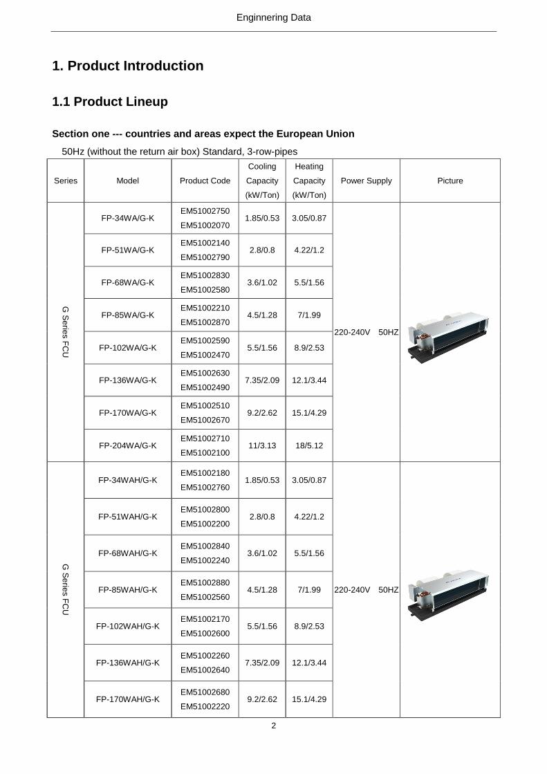
1. Product Introduction
1.1 Product Lineup
Section one --- countries and areas expect the European Union
50Hz (without the return air box) Standard, 3-row-pipes
Series Model Product Code
Cooling
Capacity
(kW/Ton)
Heating
Capacity
(kW/Ton)
Power Supply Picture
G S
erie
s F
CU
FP-34WA/G-K EM51002750
EM51002070 1.85/0.53 3.05/0.87
220-240V 50HZ
FP-51WA/G-K EM51002140
EM51002790 2.8/0.8 4.22/1.2
FP-68WA/G-K EM51002830
EM51002580 3.6/1.02 5.5/1.56
FP-85WA/G-K EM51002210
EM51002870 4.5/1.28 7/1.99
FP-102WA/G-K EM51002590
EM51002470 5.5/1.56 8.9/2.53
FP-136WA/G-K EM51002630
EM51002490 7.35/2.09 12.1/3.44
FP-170WA/G-K EM51002510
EM51002670 9.2/2.62 15.1/4.29
FP-204WA/G-K EM51002710
EM51002100 11/3.13 18/5.12
G S
erie
s F
CU
FP-34WAH/G-K
EM51002180
EM51002760 1.85/0.53 3.05/0.87
220-240V 50HZ
FP-51WAH/G-K EM51002800
EM51002200 2.8/0.8 4.22/1.2
FP-68WAH/G-K EM51002840
EM51002240 3.6/1.02 5.5/1.56
FP-85WAH/G-K EM51002880
EM51002560 4.5/1.28 7/1.99
FP-102WAH/G-K EM51002170
EM51002600 5.5/1.56 8.9/2.53
FP-136WAH/G-K EM51002260
EM51002640 7.35/2.09 12.1/3.44
FP-170WAH/G-K EM51002680
EM51002220 9.2/2.62 15.1/4.29
Enginnering Data
3
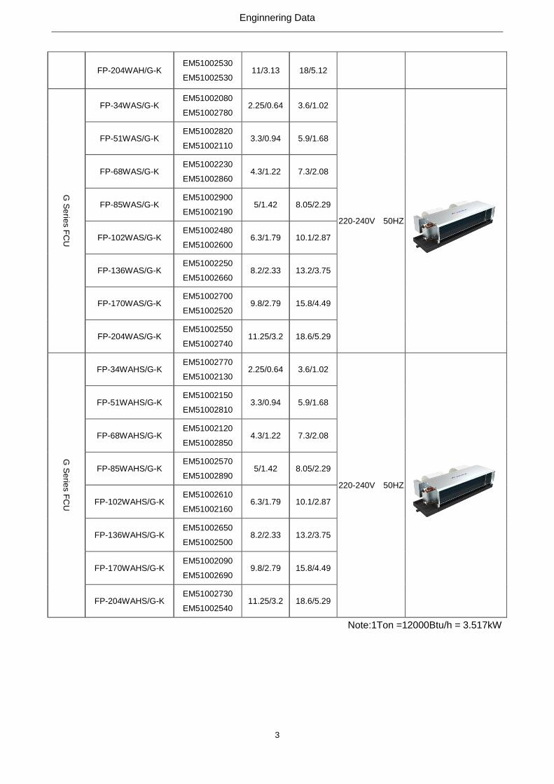
FP-204WAH/G-K EM51002530
EM51002530 11/3.13 18/5.12
G S
erie
s F
CU
FP-34WAS/G-K EM51002080
EM51002780 2.25/0.64 3.6/1.02
220-240V 50HZ
FP-51WAS/G-K EM51002820
EM51002110 3.3/0.94 5.9/1.68
FP-68WAS/G-K EM51002230
EM51002860 4.3/1.22 7.3/2.08
FP-85WAS/G-K EM51002900
EM51002190 5/1.42 8.05/2.29
FP-102WAS/G-K EM51002480
EM51002600 6.3/1.79 10.1/2.87
FP-136WAS/G-K EM51002250
EM51002660 8.2/2.33 13.2/3.75
FP-170WAS/G-K EM51002700
EM51002520 9.8/2.79 15.8/4.49
FP-204WAS/G-K EM51002550
EM51002740 11.25/3.2 18.6/5.29
G S
erie
s F
CU
FP-34WAHS/G-K EM51002770
EM51002130 2.25/0.64 3.6/1.02
220-240V 50HZ
FP-51WAHS/G-K EM51002150
EM51002810 3.3/0.94 5.9/1.68
FP-68WAHS/G-K EM51002120
EM51002850 4.3/1.22 7.3/2.08
FP-85WAHS/G-K EM51002570
EM51002890 5/1.42 8.05/2.29
FP-102WAHS/G-K EM51002610
EM51002160 6.3/1.79 10.1/2.87
FP-136WAHS/G-K EM51002650
EM51002500 8.2/2.33 13.2/3.75
FP-170WAHS/G-K EM51002090
EM51002690 9.8/2.79 15.8/4.49
FP-204WAHS/G-K EM51002730
EM51002540 11.25/3.2 18.6/5.29
Note:1Ton =12000Btu/h = 3.517kW
Enginnering Data
4
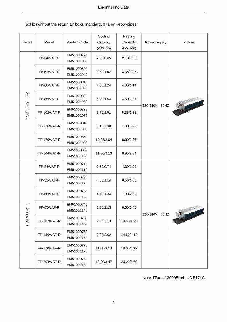
50Hz (without the return air box), standard, 3+1 or 4-row-pipes
Series Model Product Code
Cooling
Capacity
(kW/Ton)
Heating
Capacity
(kW/Ton)
Power Supply Picture
3+
1 S
erie
s F
CU
FP-34WAT-R EM51000790
EM51001030 2.30/0.65 2.10/0.60
220-240V 50HZ
FP-51WAT-R EM51000800
EM51001040 3.60/1.02 3.35/0.95
FP-68WAT-R EM51000810
EM51001050 4.35/1.24 4.00/1.14
FP-85WAT-R EM51000820
EM51001060 5.40/1.54 4.60/1.31
FP-102WAT-R EM51000830
EM51001070 6.70/1.91 5.35/1.52
FP-136WAT-R EM51000840
EM51001080 8.10/2.30 7.00/1.99
FP-170WAT-R EM51000850
EM51001090 10.35/2.94 8.30/2.36
FP-204WAT-R EM51000860
EM51001100 11.00/3.13 8.95/2.54
4 S
erie
s F
CU
FP-34WAF-R EM51000710
EM51001110 2.60/0.74 4.30/1.22
220-240V 50HZ
FP-51WAF-R EM51000720
EM51001120 4.00/1.14 6.50/1.85
FP-68WAF-R EM51000730
EM51001130 4.70/1.34 7.30/2.08
FP-85WAF-R EM51000740
EM51001140 5.60/2.13 8.60/2.45
FP-102WAF-R EM51000750
EM51001150 7.50/2.13 10.50/2.99
FP-136WAF-R EM51000760
EM51001160 9.20/2.62 14.50/4.12
FP-170WAF-R EM51000770
EM51001170 11.00/3.13 18.00/5.12
FP-204WAF-R EM51000780
EM51001180 12.20/3.47 20.00/5.69
Note:1Ton =12000Btu/h = 3.517kW

Enginnering Data
5
60HZ (without the return air box), standard
Series Model Product Code Cooling capacity
(kW/Ton)
Heating capacity
(kW/Ton) Power supply Pictures
G
FP-34WA/G-D EM51002350
EM51003310 1.9/0.54 3.05/0.87
208-230V
60HZ
FP-51WA/G-D EM51002390
EM51003390 3/0.85 5/1.42
FP-68WA/G-D EM51003430
EM51003440 3.6/1.02 5.9/1.68
FP-85WA/G-D EM51003530
EM51002450 4.7/1.34 7.7/2.19
FP-102WA/G-D EM51002920
EM51002910 5.7/1.62 9.35/2.66
FP-136WA/G-D EM51003020
EM51003010 7.35/2.09 12.1/3.44
FP-170WA/G-D EM51003120
EM51002300 9.5/2.7 15.8/4.49
FP-204WA/G-D EM51002340
EM51003200 11.5/3.27 18.8/5.35
G
FP-34WAH/G-D EM51003340
EM51002360 1.9/0.54 3.05/0.87
208-230V
60HZ
FP-51WAH/G-D EM51002400
EM51003400 3/0.85 5/1.42
FP-68WAH/G-D EM51003480
EM51003470 3.6/1.02 5.9/1.68
FP-85WAH/G-D EM51002460
EM51003560 4.7/1.34 7.7/2.19
FP-102WAH/G-D EM51002960
EM51002950 5.7/1.62 9.35/2.66
FP-136WAH/G-D EM51003050
EM51002290 7.35/2.09 12.1/3.44
FP-170WAH/G-D EM51002310
EM51003150 9.5/2.7 15.8/4.49
FP-204WAH/G-D EM51003240
EM51003230 11.5/3.27 18.8/5.35

Enginnering Data
6
60HZ (without the return air box), 3-row-pipes
Series Model Product Code
Cooling
capacity
(kW/Ton)
Heating
capacity
(kW/Ton)
Power
supply Pictures
G
FP-34WAS/G-D EM51003380
EM51002380 2.25/0.64 3.7/1.05
208-230V
60HZ
FP-51WAS/G-D EM51002420
EM51003420 3.3/0.94 5.4/1.54
FP-68WAS/G-D EM51003520
EM51002440 4.4/1.25 7.35/2.09
FP-85WAS/G-D EM51003620
EM51003610 5.2/1.48 8.5/2.42
FP-102WAS/G-D EM51003000
EM51002280 6.6/1.88 10.65/3.03
FP-136WAS/G-D EM51003110
EM51003100 8.3/2.36 13.5/3.84
FP-170WAS/G-D EM51002330
EM51003190 10.2/2.9 17/4.83
FP-204WAS/G-D EM51003300
EM51003290 12.2/3.47 20/5.69
G
FP-34WAHS/G-D EM51002370
EM51003370 2.25/0.64 3.7/1.05
208-230V
60HZ
FP-51WAHS/G-D EM51003410
EM51002410 3.3/0.94 5.4/1.54
FP-68WAHS/G-D EM51002430
EM51003510 4.4/1.25 7.35/2.09
FP-85WAHS/G-D EM51003600
EM51003590 5.2/1.48 8.5/2.42
FP-102WAHS/G-D EM51002270
EM51002990 6.6/1.88 10.65/3.03
FP-136WAHS/G-D EM51003090
EM51003080 8.3/2.35 13.5/3.84
FP-170WAHS/G-D EM51003180
EM51002320 10.2/2. 9 17/4.83
FP-204WAHS/G-D EM51003280
EM51003270 12.2/3.47 20/5.69

Enginnering Data
7
60Hz (without the return air box), 3+1 or 4-row-pipes
Series Model Product Code
Cooling
Capacity
(kW/Ton)
Heating
Capacity
(kW/Ton)
Power Supply Picture
3+
1 S
erie
s F
CU
FP-34WAT-R EM51000790
EM51001030 2.35/0.67 2.15/0.61
208~230V
60HZ
FP-51WAT-R EM51000800
EM51001040 3.80/1.08 3.40/0.97
FP-68WAT-R EM51000810
EM51001050 4.40/1.25 4.10/1.17
FP-85WAT-R EM51000820
EM51001060 5.60/1.59 4.70/1.34
FP-102WAT-R EM51000830
EM51001070 6.80/1.93 5.60/1.59
FP-136WAT-R EM51000840
EM51001080 8.20/2.33 7.20/2.05
FP-170WAT-R EM51000850
EM51001090 10.50/2.99 8.40/2.39
FP-204WAT-R EM51000860
EM51001100 11.20/3.18 9.10/2.59
4 S
erie
s F
CU
FP-34WAF-R EM51000710
EM51001110 2.65/0.75 4.35/1.24
208~230V
60HZ
FP-51WAF-R EM51000720
EM51001120 4.08/1.16 6.55/1.86
FP-68WAF-R EM51000730
EM51001130 4.80/1.36 7.40/2.10
FP-85WAF-R EM51000740
EM51001140 5.80/ 1.65 8.80/2.50
FP-102WAF-R EM51000750
EM51001150 7.60/2.16 11.50/3.27
FP-136WAF-R EM51000760
EM51001160 9.30/2.64 14.70/4.18
FP-170WAF-R EM51000770
EM51001170 11.20/3.18 18.20/5.17
FP-204WAF-R EM51000780
EM51001180 12.50/3.55 20.80/5.91
Note:1Ton =12000Btu/h = 3.517kW

Enginnering Data
8
Section two --- countries and areas within the European Union
50HZ (with the return air box), standard, 3-row pipes
Series Model Product Code
Cooling
capacity
(kW/Ton)
Heating
capacity
(kW/Ton)
Power
supply Pictures
G
FP-34WA/GHL-K EM51003330
EM51003320 1.75/0.5 2.2/0.63
220-240V
50HZ
FP-51WA/GHL-K EM51003980
EM51003970 2.9/0.82 3.4/0.97
FP-68WA/GHL-K EM51003460
EM51003450 3.4/0.97 4.2/1.19
FP-85WA/GHL-K EM51003550
EM51003540 4.3/1.22 4.7/1.34
FP-102WA/GHL-K EM51002940
EM51002930 4.9/1.39 6/1.71
FP-136WA/GHL-K EM51003040
EM51003030 6.7/1.91 8/2.27
FP-170WA/GHL-K EM51003140
EM51003130 7/1.99 9/2.56
FP-204WA/GHL-K EM51003220
EM51003210 10/2.84 11.9/3.38
G
FP-34WAH/GHL-K EM51003360
EM51003350 2/0.57 2.3/0.65
220-240V
50HZ
FP-51WAH/GHL-K EM51003950
EM51003960 3.1/0.88 3.5/1
FP-68WAH/GHL-K EM51003500
EM51003490 3.55/1.01 4.5/1.28
FP-85WAH/GHL-K EM51003580
EM51003570 4.5/1.28 4.9/1.39
FP-102WAH/GHL-K EM51002980
EM51002970 5.2/1.48 6.3/1.79
FP-136WAH/GHL-K EM51003070
EM51003060 6.9/1.96 8.2/2.33
FP-170WAH/GHL-K EM51003170
EM51003160 7.2/2.04 9.2/2.61
FP-204WAH/GHL-K EM51003260
EM51003250 10.2/2.9 12/3.4
G
FP-34WAS/GHL-K EM51003820
EM51003810 2.1/0.6 2.4/0.68
220-240V
50HZ
FP-51WAS/GHL-K EM51003930
EM51003940 3.2/0.91 3.7/1.05
FP-68WAS/GHL-K EM51003860
EM51003850 4.1/1.17 4.8/1.36
FP-85WAS/GHL-K EM51003900
EM51003890 4.8/1.36 5.5/1.56
Enginnering Data
9
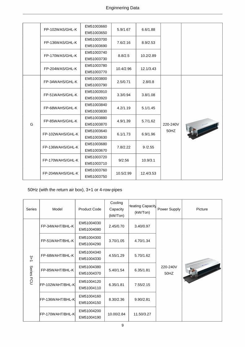
FP-102WAS/GHL-K EM51003660
EM51003650 5.9/1.67 6.6/1.88
FP-136WAS/GHL-K EM51003700
EM51003690 7.6/2.16 8.9/2.53
FP-170WAS/GHL-K EM51003740
EM51003730 8.8/2.5 10.2/2.89
FP-204WAS/GHL-K EM51003780
EM51003770 10.4/2.96 12.1/3.43
G
FP-34WAHS/GHL-K EM51003800
EM51003790 2.5/0.71 2.8/0.8
220-240V
50HZ
FP-51WAHS/GHL-K EM51003910
EM51003920 3.3/0.94 3.8/1.08
FP-68WAHS/GHL-K EM51003840
EM51003830 4.2/1.19 5.1/1.45
FP-85WAHS/GHL-K EM51003880
EM51003870 4.9/1.39 5.7/1.62
FP-102WAHS/GHL-K EM51003640
EM51003630 6.1/1.73 6.9/1.96
FP-136WAHS/GHL-K EM51003680
EM51003670 7.8/2.22 9 /2.55
FP-170WAHS/GHL-K EM51003720
EM51003710 9/2.56 10.9/3.1
FP-204WAHS/GHL-K EM51003760
EM51003750 10.5/2.99 12.4/3.53
50Hz (with the return air box), 3+1 or 4-row-pipes
Series Model Product Code
Cooling
Capacity
(kW/Ton)
Heating Capacity
(kW/Ton) Power Supply Picture
3+
1 S
erie
s F
CU
FP-34WAHT/BHL-K EM51004030
EM51004080 2.45/0.70 3.40/0.97
220-240V
50HZ
FP-51WAHT/BHL-K EM51004300
EM51004290 3.70/1.05 4.70/1.34
FP-68WAHT/BHL-K EM51004340
EM51004330 4.55/1.29 5.70/1.62
FP-85WAHT/BHL-K EM51004380
EM51004370 5.40/1.54 6.35/1.81
FP-102WAHT/BHL-K EM51004120
EM51004110 6.35/1.81 7.55/2.15
FP-136WAHT/BHL-K EM51004160
EM51004150 8.30/2.36 9.90/2.81
FP-170WAHT/BHL-K EM51004200
EM51004190 10.00/2.84 11.50/3.27

Enginnering Data
10
FP-204WAHT/BHL-K EM51004240
EM51004230 10.2/2.90 11.90/3.38
4 S
erie
s F
CU
FP-34WAHF/BHL-K EM51004260
EM51004250 2.65/0.75 3.15/0.90
220-240V
50HZ
FP-51WAHF/BHL-K EM51004280
EM51004270 3.80/1.08 4.40/1.25
FP-68WAHF/BHL-K EM51004320
EM51004310 5.00/1.42 5.45/1.55
FP-85WAHF/BHL-K EM51004360
EM51004350 5.70/1.62 6.15/1.75
FP-102WAHF/BHL-K EM51004100
EM51004090 7.10/2.02 7.30/2.08
FP-136WAHF/BHL-K EM51004140
EM51004130 8.90/2.53 9.50/2.70
FP-170WAHF/BHL-K EM51004180
EM51004170 11.00/3.13 12.30/3.50
FP-204WAHF/BHL-K EM51004220
EM51004210 11.20/3.18 13.00/3.70
Note:1Ton =12000Btu/h = 3.517kW
1.2 Nomenclature

Enginnering Data
11
1.3 Product Features
1.3.1 Features
FCU is the most widely used terminal unit of the air conditioning system, used fo supplying cooling
(hot) water, with the air flow below 2500m3/h and the external static pressure less than 100Pa. For
cooling, enthalpy loss of the air generally is 15.9kJ/kg. For hot water under 60℃, the cheating capacity is
1.5 times of the cooling capacity.
As the terminal unit of the central air conditioning system, it is widely used in public areas with the
following main features:
a. Three speeds are selectable for the air flow. According to the set point of the room temperature,
the water system can be controlled by the hot/cool water automatic regulating valve so that
temperature for each room can be controlled separately for meeting different requirements.
Where no one is inside the room, it can be turned off manually or by the timing function, which
will lower the operation cost of the whole system.
b. The zone control is available based on direction, height, utilization and service time, which can
avoid unreasonable conceptualized control of the large-sized duct system.
c. Compact structure, flexible arrangement, and easy installation will save installation space and
facilitate indoor decoration.
There are various structures with the same air flow and cooling capacity for different room structure,
different decoration and duct arrangement.
(1) Plastic Fan
a. Light-weighted, which will lead to increased air flow driven by the same motor.
b. Good compatibility of the angle of the blades and the cavity of the volute, which will lead to silent
operation.
c. CFD designed flow and angle of fan blades, for high operation efficiency
d. The volute is divided into the upper and lower parts, which will facilitate disassembly.
(2) CFD Designed Fan
a. Optimized flow structure
b. Evenly distributed air flow and low flow noise
c. less eddy flow
d. Novel style and advanced structure
e. Decreased height , saving installation space
f. Low noise and three fan speeds
g. High-quality material and strict processing control for guaranteeing quality and service life of
the whole unit.
h. Die formed drain pan with the entirely pressured and pasted insulation, generating no
Enginnering Data
12
condensate
i. Optimized location of the exhaust and drain valves, for better heat exchanging effect and
preventing from frost cracks in winter.
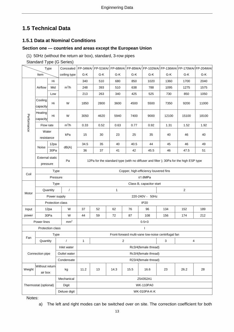
(3) High-efficiency copper tubes
The copper tubes are made of pure red copper with female threads on the inner wall. There are also
raised teeth at the inner wall, used for increasing turbulent flows and damaging the boundary layer of
water for better heat exchanging capacity.
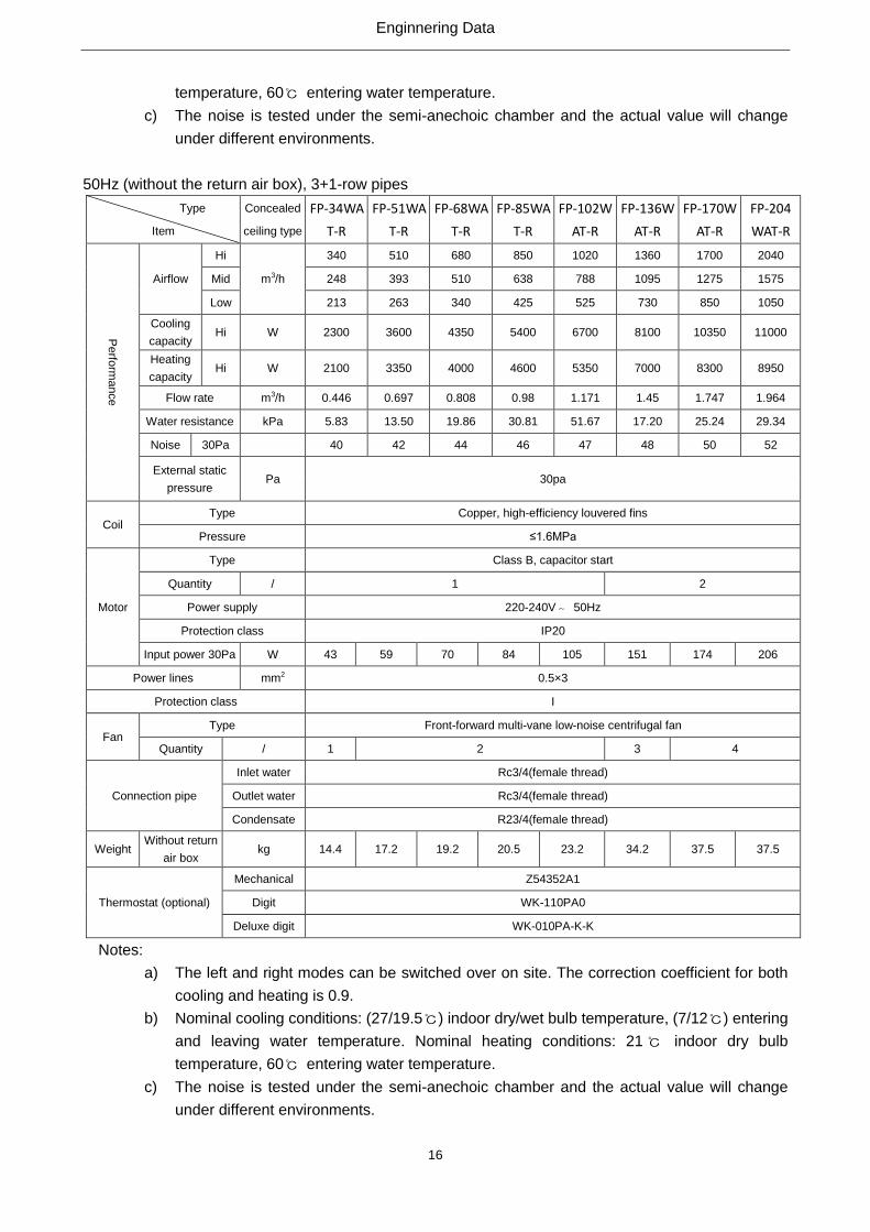
(4) The Cooler with the Interchangeable Left/Right Structure
During installation, the left-type and right-type structure can be selected flexibly as steps stated below:
Step 1: Remove the centrifugal fan, cover plate and screws of the electric box.
Step 2: Move the side plate at the air outlet to the other side.
Step 3: Rotate the fan assembly and the cover plate for 180°and then fix them.
Step 4: Remove the electric box to the other side and then fix it..
1.: Cover plate; 2. Centrifugal fan; 3. Side plate at the air outlet
Left-type Unit Right-type Unit
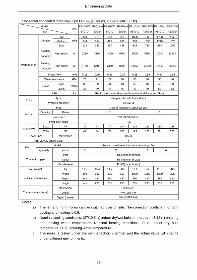
1.4 Working Principle
The cool (hot) water goes in the fan coil and makes heat exchanging with the indoor circulated air
(outdoor air), to realize cooling(heating), dehumidifying, filtrating or purifying. The processed air will be
supplied to indoor directly or by air duct.
Enginnering Data
13
1.5 Technical Data
1.5.1 Data at Nominal Conditions
Section one --- countries and areas except the European Union
(1) 50Hz (without the return air box), standard, 3-row pipes
Standard Type (G Series)
Type
Item
Concealed
ceiling type
FP-34WA/
G-K
FP-51WA/
G-K
FP-68WA/
G-K
FP-85WA/
G-K
FP-102WA/
G-K
FP-136WA/
G-K
FP-170WA/
G-K
FP-204WA/
G-K
Perfo
rma
nce
Airflow
Hi
m3/h
340 510 680 850 1020 1360 1700 2040
Mid 248 393 510 638 788 1095 1275 1575
Low 213 263 340 425 525 730 850 1050
Cooling
capacity Hi W 1850 2800 3600 4500 5500 7350 9200 11000
Heating
capacity Hi W 3050 4620 5940 7400 9000 12100 15100 18100
Flow rate m3/h 0.33 0.52 0.63 0.77 0.92 1.31 1.52 1.92
Water
resistance kPa 15 30 23 25 35 40 46 40
Noise 12pa
dB(A) 34.5 35 40 40.5 44 45 46 49
30Pa 36 37 41 42 45.5 46 47.5 51
External static
pressure Pa 12Pa for the standard type (with no diffuser and filter ); 30Pa for the high ESP type
Coil Type Copper, high-efficiency louvered fins
Pressure ≤1.6MPa
Motor
Type Class B, capacitor start
Quantity / 1 2
Power supply 220-240V~ 50Hz
Protection class IP20
Input
power
12pa W 37 52 62 76 96 134 152 189
30Pa W 44 59 72 87 108 156 174 212
Power lines mm2 0.5×3
Protection class I
Fan Type Front-forward multi-vane low-noise centrifugal fan
Quantity / 1 2 3 4
Connection pipe
Inlet water Rc3/4(female thread)
Outlet water Rc3/4(female thread)
Condensate R23/4(female thread)
Weight Without return
air box kg 11.2 13 14.3 15.5 16.6 23 26.2 28
Thermostat (optional)
Mechanical Z54352A1
Digit WK-110PA0
Deluxe digit WK-010PA-K-K
Notes:
a) The left and right modes can be switched over on site. The correction coefficient for both

Enginnering Data
14
cooling and heating is 0.9.
b) Nominal cooling conditions: (27/19.5℃) indoor dry/wet bulb temperature, (7/12℃) entering
and leaving water temperature. Nominal heating conditions: 21℃ indoor dry bulb
temperature, 60℃ entering water temperature.
c) The noise is tested under the semi-anechoic chamber and the actual value will change
under different environments.
Three-row type
Model
Item
Concealed
ceiling type
FP-34W
AS/G-K
FP-51W
AS/G-K
FP-68W
AS/G-K
FP-85W
AS/G-K
FP-102
WAS/G-
K
FP-136
WAS/G-
K
FP-170
WAS/G-
K
FP-204
WAS/G-
K
Perfo
rma
nce
Air flow
Hi
m3/h
340 510 680 850 1020 1360 1700 2040
Mid 248 394 495 638 788 1095 1275 1575
Low 173 263 330 425 525 730 850 1050
Cooling
capacity Hi W 2250 3300 4300 5000 6300 8200 9800 11250
Heating
capacity Hi W 3600 5300 6930 8050 10100 13200 15800 18600
Water flow m3/h 0.4 0.57 0.76 0.88 0.99 1.41 1.68 1.95
Water resistance kPa 20 21 22 30 35 40 33 40
Noise 12pa
dB(A) 34.5 37 38.5 41 44 45 46.5 50
30Pa 36 38 41 43 46 47 47.5 51.5
External static
pressure Pa 12Pa for the standard type (with no diffuser and filter ); 30Pa for the high ESP type
Coil Type Copper, high-efficiency louvered fins
Pressure ≤1.6MPa
Motor
Type Class B, capacitor start
Quantity / 1 2
Power supply 220V~ 50Hz
Protection class IP20
Input
power
12pa W 37 52 62 76 96 134 152 189
30Pa W 44 59 72 87 108 156 174 212
Power lines mm2 0.5×3
Protection class I
Fan Type Front-forward multi-vane low-noise centrifugal fan
Quantity / 1 2 3 4
Connection pipe
Inlet water Rc3/4(female thread)
Outlet water Rc3/4(female thread)
Condensate R2c3/4(female thread)
Weight
Without the
return air box kg 11.6 13.4 14.7 16 17.4 24 26.6 28.5
With the return
air box kg
Thermostat (optional)
Mechanical Z54352A1
Digit WK-110PA0
Deluxe digit WK-010PA-K-K
Notes:
a) The left and right modes can be switched over on site. The correction coefficient for both

Enginnering Data
15
cooling and heating is 0.9.
b) Nominal cooling conditions: (27/19.5℃) indoor dry/wet bulb temperature, (7/12℃) entering
and leaving water temperature. Nominal heating conditions: 21℃ indoor dry bulb
temperature, 60℃ entering water temperature.
c) The noise is tested under the semi-anechoic chamber and the actual value will change
under different environments.
50Hz (without the return air box), 4-row pipes
Type
Item
Concealed
ceiling type
FP-34WA
F-R
FP-51WA
F-R
FP-68WA
F-R
FP-85WA
F-R
FP-102W
AF-R
FP-136W
AF-R
FP-170W
AF-R
FP-204W
AF-R
Perfo
rma
nce
Airflow
Hi
m3/h
340 510 680 850 1020 1360 1700 2040
Mid 248 393 510 638 788 1095 1275 1575
Low 213 263 340 425 525 730 850 1050
Cooling
capacity Hi W 2600 4000 4700 5600 7500 9200 11000 12200
Heating
capacity Hi W 4300 6500 7300 8600 10500 14500 18000 20000
Flow rate m3/h 0.464 0.729 0.893 0.981 1.318 1.615 2.042 2.229
Water resistance kPa 3.713 8.943 14.54 18.79 35.75 19.06 29.01 35.41
Noise 30Pa
40 42 44 46 47 48 50 52
External static
pressure Pa 30pa
Coil Type Copper, high-efficiency louvered fins
Pressure ≤1.6MPa
Motor
Type Class B, capacitor start
Quantity / 1 2
Power supply 220-240V~ 50Hz
Protection class IP20
Input power
30Pa W 43 59 70 84 105 151 174 206
Power lines mm2 0.5×3
Protection class I
Fan Type Front-forward multi-vane low-noise centrifugal fan
Quantity / 1 2 3 4
Connection pipe
Inlet water Rc3/4(female thread)
Outlet water Rc3/4(female thread)
Condensate R23/4(female thread)
Weight Without return
air box kg 14.4 17.2 19.2 20.5 23.2 34.2 37.5 37.5
Thermostat (optional)
Mechanical Z54352A1
Digit WK-110PA0
Digital (deluxe) WK-010PA-K-K
Notes:
a) The left and right modes can be switched over on site. The correction coefficient for both
cooling and heating is 0.9.
b) Nominal cooling conditions: (27/19.5℃) indoor dry/wet bulb temperature, (7/12℃) entering
and leaving water temperature. Nominal heating conditions: 21℃ indoor dry bulb
Enginnering Data
16
temperature, 60℃ entering water temperature.
c) The noise is tested under the semi-anechoic chamber and the actual value will change
under different environments.
50Hz (without the return air box), 3+1-row pipes
Type
Item
Concealed
ceiling type
FP-34WA
T-R
FP-51WA
T-R
FP-68WA
T-R
FP-85WA
T-R
FP-102W
AT-R
FP-136W
AT-R
FP-170W
AT-R
FP-204
WAT-R
Perfo
rma
nce
Airflow
Hi
m3/h
340 510 680 850 1020 1360 1700 2040
Mid 248 393 510 638 788 1095 1275 1575
Low 213 263 340 425 525 730 850 1050
Cooling
capacity Hi W 2300 3600 4350 5400 6700 8100 10350 11000
Heating
capacity Hi W 2100 3350 4000 4600 5350 7000 8300 8950
Flow rate m3/h 0.446 0.697 0.808 0.98 1.171 1.45 1.747 1.964
Water resistance kPa 5.83 13.50 19.86 30.81 51.67 17.20 25.24 29.34
Noise 30Pa
40 42 44 46 47 48 50 52
External static
pressure Pa 30pa
Coil Type Copper, high-efficiency louvered fins
Pressure ≤1.6MPa
Motor
Type Class B, capacitor start
Quantity / 1 2
Power supply 220-240V~ 50Hz
Protection class IP20
Input power 30Pa W 43 59 70 84 105 151 174 206
Power lines mm2 0.5×3
Protection class I
Fan Type Front-forward multi-vane low-noise centrifugal fan
Quantity / 1 2 3 4
Connection pipe
Inlet water Rc3/4(female thread)
Outlet water Rc3/4(female thread)
Condensate R23/4(female thread)
Weight Without return
air box kg 14.4 17.2 19.2 20.5 23.2 34.2 37.5 37.5
Thermostat (optional)
Mechanical Z54352A1
Digit WK-110PA0
Deluxe digit WK-010PA-K-K
Notes:
a) The left and right modes can be switched over on site. The correction coefficient for both
cooling and heating is 0.9.
b) Nominal cooling conditions: (27/19.5℃) indoor dry/wet bulb temperature, (7/12℃) entering
and leaving water temperature. Nominal heating conditions: 21℃ indoor dry bulb
temperature, 60℃ entering water temperature.
c) The noise is tested under the semi-anechoic chamber and the actual value will change
under different environments.

Enginnering Data
17
(2) 60Hz (without the return air box), standard, 3-row pipes
Horizontal concealed FCU— (G series, 208-230VAC 60Hz)
Model
Item Unit
FP-34WA/
G-D
FP-51WA/
G-D
FP-68WA/
G-D
FP-85WA/
G-D
FP-102WA/
G-D
FP-136WA/
G-D
FP-170WA/
G-D
FP-204WA/
G-D
Perfo
rma
nce
Air flow
High
m³/h
340 510 680 850 1020 1360 1700 2040
Medium 248 394 495 638 788 1095 1275 1575
Low 173 263 330 425 525 730 850 1050
Cooling
capacity High W 1900 3000 3600 4700 5700 7350 9500 11500
Heating
capacity High W 3050 5000 5900 7700 9350 12100 15800 18800
Water flow m³/h 0.10 0.14 0.18 0.21 0.26 0.36 0.42 0.53
Water resistance kPa 15 30 23 25 35 40 36 40
Noise 12pa
dB(A) 34.5 38 40 43 45 46 48 50
30Pa 36 39 42 46 47.5 48 50 52
ESP Pa 12Pa for the standard type (without the air diffuser and filter)
30Pa for the high static pressure type
Coils Type Copper tube with lourved fins
Working pressure ≤1.6MPa
Motor
Type Class B insulation, capacitor start
Quantity Piece 1 2
Power supply 208-230VAC 60Hz
Protection class IP20
Input
power
12pa W 36 57 70 104 105 164 180 228
30Pa W 49 58 74 105 123 165 221 273
Power lines mm2×piece 0.5×3
Anti electric shock class I
Fan Type Forward multi-vane low-noise centrifugal fan
Quantity piece 1 2 3 4
Connection pipe
Inlet Rc3/4(inner thread)
Outlet Rc3/4(inner thread)
Condensate Rc3/4(outer thread)
Net weight kg 11.2 13 14.3 15.5 16.6 23 26.2 28
Outline
dimensions
Width mm 680 800 900 1000 1080 1380 1520 1620
Depth mm 490 460 490 490 490 490 490 490
Height mm 235 235 235 235 235 235 235 235
Thermostat (optional)
Mechanical Z54352A1
Digital WK-110PA0
Digital (deluxe) WK-010PA-K-K
Notes:
a) The left and right modes can be switched over on site. The correction coefficient for both
cooling and heating is 0.9.
b) Nominal cooling conditions: (27/19.5℃) indoor dry/wet bulb temperature, (7/12℃) entering
and leaving water temperature. Nominal heating conditions: 21℃ indoor dry bulb
temperature, 60℃ entering water temperature.
c) The noise is tested under the semi-anechoic chamber and the actual value will change
under different environments.
Enginnering Data
18
Horizontal concealed three-row-pipe FCU— (G series, 208-230VAC 60Hz)
Model
Item Unit
FP-34WA
S/G-D
FP-51WA
S/G-D
FP-68WA
S/G-D
FP-85WA
S/G-D
FP-102W
AS/G-D
FP-136W
AS/G-D
FP-170W
AS/G-D
FP-204W
AS/G-D
Performance
Air flow
High
m³/h
340 510 680 850 1020 1360 1700 2040
Medium 248 394 495 638 788 1095 1275 1575
Low 173 263 330 425 525 730 850 1050
Cooling
capacity High-speed W 2250 3300 4400 5200 6600 8300 10200 12200
Heating
capacity High-speed W 3700 5400 7350 8500 10650 13500 17000 20000
Water flow m³/h 0.11 0.16 0.21 0.24 0.28 0.39 0.47 0.54
Water resistance kPa 20 21 22 30 35 40 33 40
Noise 12pa
dB(A) 35 39 41 43 46 46 48 50
30Pa 38 40 44 46 48 49 50 52
ESP Pa 12Pa for the standard type (without the air diffuser and filter)
30Pa for the high static pressure type Coils
Type Copper tube with lourved fins
Working pressure ≤1.6MPa
Motor
Type Class B insulation, capacitor start
Quantity Piece 1 2
Power lines 208-230VAC 60Hz
Protection class IP20
Input power 12pa W 36 63 70 104 114 182 180 228
30Pa W 49 64 74 105 123 183 221 273
Power lines mm2×piece 0.5×3
Anti electric shock class I
Fan Model Forward multi-vane low-noise centrifugal fan
Quantity piece 1 2 3 4
Connection pipe
Inlet Rc3/4(inner thread)
Outlet Rc3/4(inner thread)
Condensate Rc3/4(outer thread)
Net weight kg 11.6 13.4 14.7 16 17.4 24 26.6 28.5
Outline dimensions
Width mm 680 800 900 1000 1080 1380 1520
Depth mm 490 460 490 490 490 490 490
Height mm 235 235 235 235 235 235 235
Thermostat (optional)
Mechanical Z54352A1
Digital WK-110PA0
Digital (deluxe) WK-010PA-K-K
Notes:
a) The left and right modes can be switched over on site. The correction coefficient for both
cooling and heating is 0.9.
b) Nominal cooling conditions: (27/19.5℃) indoor dry/wet bulb temperature, (7/12℃) entering
and leaving water temperature. Nominal heating conditions: 21℃ indoor dry bulb
temperature, 60℃ entering water temperature.
c) The noise is tested under the semi-anechoic chamber and the actual value will change
under different environments.

Enginnering Data
19
(3) 60 Hz (Without the return air box), 4-row pipes
Type
Item
Concealed
ceiling type
FP-34WAF
-R
FP-51WAF
-R
FP-68WAF
-R
FP-85WAF
-R
FP-102WA
F-R
FP-136WA
F-R
FP-170WA
F-R
FP-204W
AF-R
Perfo
rma
nce
Airflow
Hi
m3/h
340 590 690 820 1040 1490 1850 2160
Mid 248 393 510 638 788 1095 1275 1575
Low 213 263 340 425 525 730 850 1050
Cooling
capacity Hi W 2650 4080 4800 5800 7600 9300 11200 12500
Heating
capacity Hi W 4350 6550 7400 8800 11500 14700 18200 20800
Flow rate m3/h 0.464 0.729 0.893 0.981 1.318 1.615 2.042 2.229
Water resistance kPa 8 9 18 21 41 21 32 34
Noise 30Pa
40 42 44 46 47 48 50 52
External static
pressure Pa 30pa
Coil Type Copper, high-efficiency louvered fins
Pressure ≤1.6MPa
Motor
Type Class B, capacitor start
Quantity / 1 2
Power supply 220-240V~ 50Hz
Protection class IP20
Input power 30Pa W 49 80 82 103 140 192 217 277
Power lines mm2 0.5×3
Protection class I
Fan Type Front-forward multi-vane low-noise centrifugal fan
Quantity / 1 2 3 4
Connection pipe
Inlet water Rc3/4(female thread)
Outlet water Rc3/4(female thread)
Condensate R23/4(female thread)
Weight Without return
air box kg 14.4 17.2 19.2 20.5 23.2 34.2 37.5 37.5
Thermostat (optional)
Mechanical Z54352A1
Digit WK-110PA0
Deluxe digit WK-010PA-K-K
Enginnering Data
20
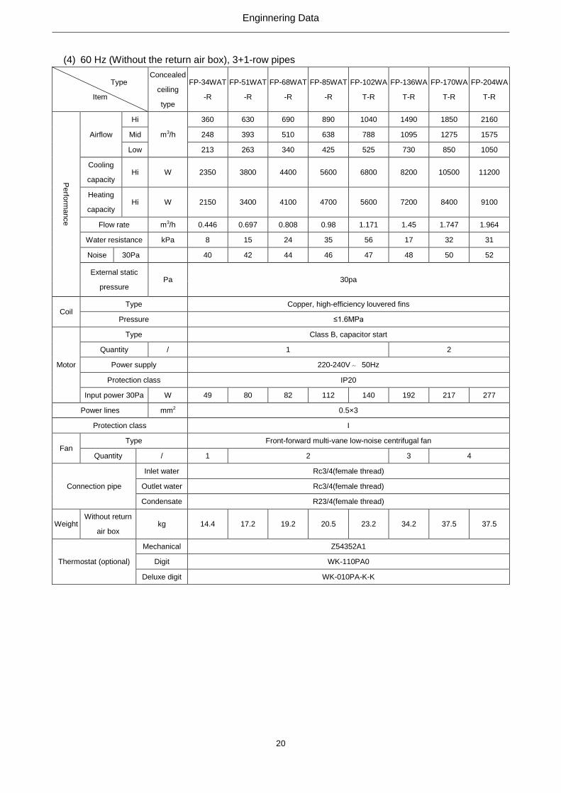
(4) 60 Hz (Without the return air box), 3+1-row pipes
Type
Item
Concealed
ceiling
type
FP-34WAT
-R
FP-51WAT
-R
FP-68WAT
-R
FP-85WAT
-R
FP-102WA
T-R
FP-136WA
T-R
FP-170WA
T-R
FP-204WA
T-R
Perfo
rma
nce
Airflow
Hi
m3/h
360 630 690 890 1040 1490 1850 2160
Mid 248 393 510 638 788 1095 1275 1575
Low 213 263 340 425 525 730 850 1050
Cooling
capacity Hi W 2350 3800 4400 5600 6800 8200 10500 11200
Heating
capacity Hi W 2150 3400 4100 4700 5600 7200 8400 9100
Flow rate m3/h 0.446 0.697 0.808 0.98 1.171 1.45 1.747 1.964
Water resistance kPa 8 15 24 35 56 17 32 31
Noise 30Pa
40 42 44 46 47 48 50 52
External static
pressure Pa 30pa
Coil Type Copper, high-efficiency louvered fins
Pressure ≤1.6MPa
Motor
Type Class B, capacitor start
Quantity / 1 2
Power supply 220-240V~ 50Hz
Protection class IP20
Input power 30Pa W 49 80 82 112 140 192 217 277
Power lines mm2 0.5×3
Protection class I
Fan Type Front-forward multi-vane low-noise centrifugal fan
Quantity / 1 2 3 4
Connection pipe
Inlet water Rc3/4(female thread)
Outlet water Rc3/4(female thread)
Condensate R23/4(female thread)
Weight Without return
air box kg 14.4 17.2 19.2 20.5 23.2 34.2 37.5 37.5
Thermostat (optional)
Mechanical Z54352A1
Digit WK-110PA0
Deluxe digit WK-010PA-K-K

Enginnering Data
21
Section two --- countries and areas within the European Union
Horizontal concealed FCU, standard (G series, 220~240VAC, 50Hz, EU)
Model
Item
Unit
FP-34WA
/GHL-K
FP-51WA
/GHL-K
FP-68WA
/GHL-K
FP-85WA
/GHL-K
FP-102W
A/GHL-K
FP-136W
A/GHL-K
FP-170W
A/GHL-K
FP-204W
A/GHL-K
Pe
rform
an
ce
Air flow
High
m³/h
370 570 720 870 1020 1360 1600 1900
Medium 260 400 504 610 788 1095 1120 1330
Low 180 280 353 426 525 730 784 931
Cooling
capacity
High W 1750
2900
3400
4300
4900
6700
7000
10000
Heating
capacity
High W 2200
3400
4200
4700
6000
8000
9000
18900
Water flow m³/h 0.10 0.14 0.18 0.21 0.26 0.36 0.42 0.53
Water resistance kPa 15 30 23 25 35 40 36 40
Noise dB(A) 37 38 40.5 44 46 46 47 50.5
External static
pressure Pa 0Pa
Coils Type Copper tube and lourved fins
Working pressure ≤1.6MPa
Motor
Type Class B insulation, capacitor start
Quantity piece 1 2
Power lines 220-240V~ 50Hz
Protection class IP20
Input power W 35 54 66 84 101 150 154 198
Power lines mm2×piece 0.5×3
Anti electric shock class I
Fan Type Forward multiple-vane low-noise centrifugal fan
Quantity piece 1 2 3 4
Connection pipe
inlet Rc3/4(inner thread)
outlet Rc3/4(inner thread)
condensate Rc3/4(external thread)
Net weight kg 14.5 17 18.9 20.8 21.9 31.5 34.1 38
Outline
dimensions
Width mm 680 800 900 1000 1080 1380 1520 1620
Depth mm 500 500 500 500 500 500 500 500
Height mm 235 235 235 235 235 235 235 235
Thermostat (optional)
Mechanical Z54352A1
Digital WK-110PA0
Digital
(deluxe) WK-010PA-K-K
Notes:
a) The left and right modes can be switched over on site. The correction coefficient for both
cooling and heating is 0.9.
b) Nominal cooling conditions: (27/19.5℃) indoor dry/wet bulb temperature, (7/12℃) entering
and leaving water temperature. Nominal heating conditions: 20℃ indoor dry bulb
temperature, 45℃ entering water temperature and 40℃ leaving water temperature.
c) The noise is tested under the semi-anechoic chamber and the actual value will change
under different environments.
Enginnering Data
22
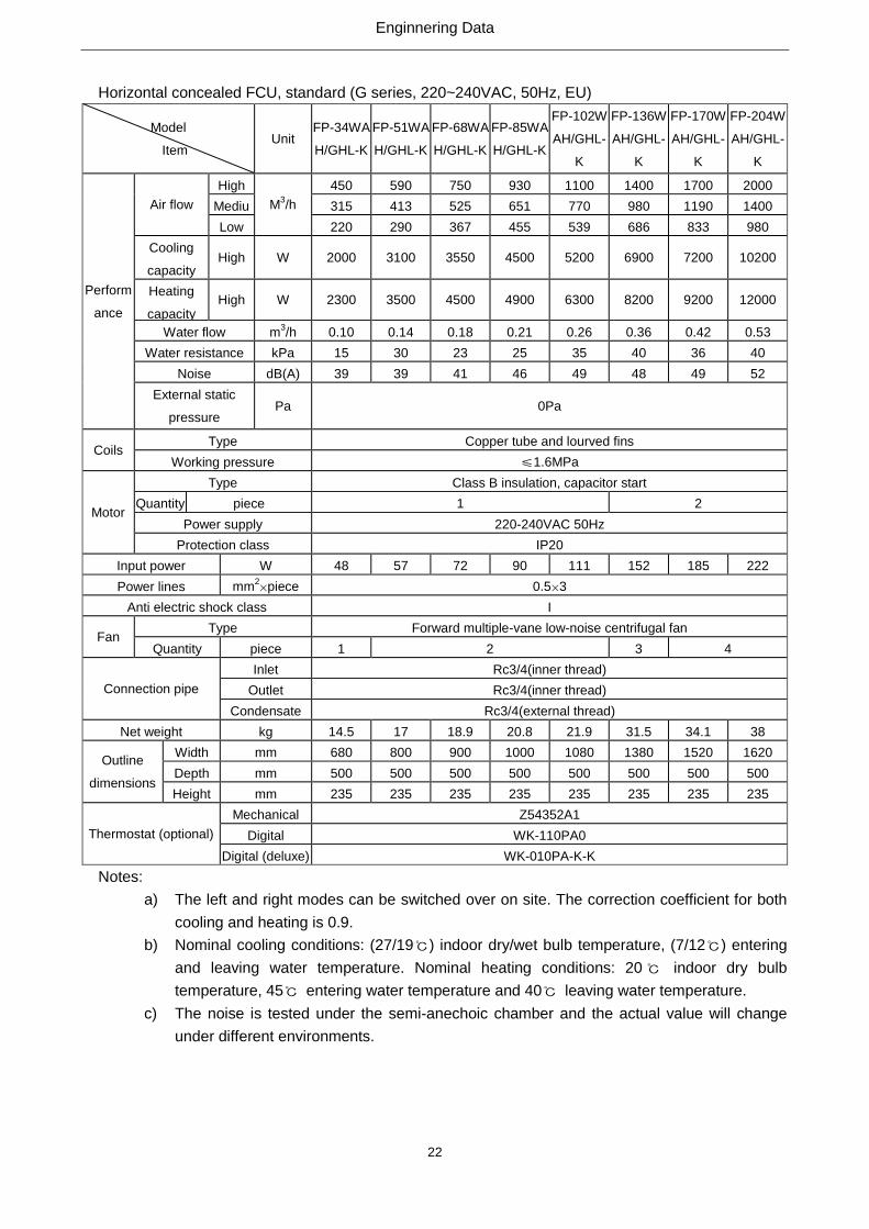
Horizontal concealed FCU, standard (G series, 220~240VAC, 50Hz, EU)
Model
Item Unit
FP-34WA
H/GHL-K
FP-51WA
H/GHL-K
FP-68WA
H/GHL-K
FP-85WA
H/GHL-K
FP-102W
AH/GHL-
K
FP-136W
AH/GHL-
K
FP-170W
AH/GHL-
K
FP-204W
AH/GHL-
K
Perform
ance
Air flow
High
M3/h
450 590 750 930 1100 1400 1700 2000
Mediu
m
315 413 525 651 770 980 1190 1400
Low 220 290 367 455 539 686 833 980
Cooling
capacity High W 2000 3100 3550 4500 5200 6900 7200 10200
Heating
capacity High W 2300 3500 4500 4900 6300 8200 9200 12000
Water flow m3/h 0.10 0.14 0.18 0.21 0.26 0.36 0.42 0.53
Water resistance kPa 15 30 23 25 35 40 36 40
Noise dB(A) 39 39 41 46 49 48 49 52
External static
pressure Pa 0Pa
Coils Type Copper tube and lourved fins
Working pressure ≤1.6MPa
Motor
Type Class B insulation, capacitor start
Quantity piece 1 2
Power supply 220-240VAC 50Hz
Protection class IP20
Input power W 48 57 72 90 111 152 185 222
Power lines mm2×piece 0.5×3
Anti electric shock class I
Fan Type Forward multiple-vane low-noise centrifugal fan
Quantity piece 1 2 3 4
Connection pipe
Inlet Rc3/4(inner thread)
Outlet Rc3/4(inner thread)
Condensate Rc3/4(external thread)
Net weight kg 14.5 17 18.9 20.8 21.9 31.5 34.1 38
Outline
dimensions
Width mm 680 800 900 1000 1080 1380 1520 1620
Depth mm 500 500 500 500 500 500 500 500
Height mm 235 235 235 235 235 235 235 235
Thermostat (optional)
Mechanical Z54352A1
Digital WK-110PA0
Digital (deluxe) WK-010PA-K-K
Notes:
a) The left and right modes can be switched over on site. The correction coefficient for both
cooling and heating is 0.9.
b) Nominal cooling conditions: (27/19℃) indoor dry/wet bulb temperature, (7/12℃) entering
and leaving water temperature. Nominal heating conditions: 20℃ indoor dry bulb
temperature, 45℃ entering water temperature and 40℃ leaving water temperature.
c) The noise is tested under the semi-anechoic chamber and the actual value will change
under different environments.

Enginnering Data
23
Horizontal concealed FCU, 3-row-pipes (G series, 220~240VAC, 50Hz, EU)
Model
Item Unit
FP-34WA
S/GHL-K
FP-51WA
S/GHL-K
FP-68WA
S/GHL-K
FP-85WA
S/GHL-K
FP-102W
AS/GHL-K
FP-136W
AS/GHL-K
FP-170W
AS/GHL-K
FP-204W
AS/GHL-K
Pe
rform
an
ce
Air flow
High
m3/h
370 570 720 870 1020 1360 1600 1900
Mediu
m
260 400 504 610 788 1095 1120 1330
Low 180 280 353 426 525 730 784 931
Cooling
capacity High W 2100 3200 4100 4800 5900 7600 8800 10400
Heating
capacity High W 2400 3700 4800 5500 6600 8900 10200 12100
Water flow M3/h 0.11 0.16 0.21 0.24 0.28 0.39 0.47 0.54
Water resistance kPa 20 21 22 30 35 40 33 40
Noise dB(A) 37 39 40.5 44 48 47 48 50.5
External static
pressure Pa 0Pa
Coils Type Copper tube and lourved fins
Working pressure ≤1.6MPa
Motor
Type Class B insulation, capacitor start
Quantity piece 1 2
Power supply 220-240V~ 50Hz
Protection class IP20
Input power W 35 58 66 78 102 161 150 192
Power lines mm2×piece 0.5×3
Anti-electric shock class I
Fan Type Forward multiple-vane low noise centrifugal fan
Quantity Piece 1 2 3 4
Connection pipe
Inlet Rc3/4(inner thread)
Outlet Rc3/4(inner thread)
Condensate Rc3/4(external thread)
Net weight kg 14.9 17.4 19.3 21.3 22.7 30.9 34.5 38
Outline
dimensions
Width mm 680 800 900 1000 1080 1380 1520
Depth mm 500 500 500 500 500 500 500
Height mm 235 235 235 235 235 235 235
Thermostat
(optional)
Mechanical Z54352A1
Digital WK-110PA0
Digital (Deluxe) WK-010PA-K-K
Notes:
a) The left and right modes can be switched over on site. The correction coefficient for both
cooling and heating is 0.9.
b) Nominal cooling conditions: (27/19℃) indoor dry/wet bulb temperature, (7/12℃) entering
and leaving water temperature. Nominal heating conditions: 20℃ indoor dry bulb
temperature, 45℃ entering water temperature and 40℃ leaving water temperature.
c) The noise is tested under the semi-anechoic chamber and the actual value will change
under different environments.

Enginnering Data
24
Horizontal concealed FCU, 3-row-pipe (G series, 220~240VAC, 50Hz, EU)
Model
Item Unit
FP-34WA
HS/GHL-
K
FP-51WA
HS/GHL-
K
FP-68WA
HS/GHL-
K
FP-85WA
HS/GHL-
K
FP-102WA
HS/GHL-K
FP-136WA
HS/GHL-K
FP-170WA
HS/GHL-K
FP-204WA
HS/GHL-K
Pe
rform
an
ce
Air flow
High
m3/h
450 590 750 930 1100 1400 1700 2000
Mediu
m
315 413 525 651 770 980 1190 1400
Low 220 290 367 455 539 686 833 980
Cooling
capacity High W 250 3300 4200 4900 6100 7800 9000 10500
Heating
capacity High W 2800 3800 5100 5700 6900 9000 10900 12400
Water flow M3/h 0.11 0.16 0.21 0.24 0.28 0.39 0.47 0.54
Water resistance kPa 20 21 22 30 35 40 33 40
Noise dB(A) 39 40 42 46 49 49 49 52
External static
pressure Pa 0Pa
Coils Type Copper tube with lourved fins
Working pressure ≤1.6MPa
Motor
Type Class B insulation, capacitor start
Quantity piece 1 2
Power supply 220-240VAC 50Hz
Protection class IP20
Input power W 46 57 72 83 108 164 185 221
Power lines mm2×piece
s
0.5×3
Anti electric shock class I
Fan Type Forward multi-vane low-noise centrifugal fan
Quantity 个 1 2 3 4
Connection pipe
Inlet Rc3/4(inner thread)
Outlet Rc3/4(inner thread)
Condensat
e
Rc3/4(external thread)
Net weiht kg 14.9 17.4 19.3 21.3 22.7 30.9 34.5 38
Outline dimensions
Width mm 680 800 900 1000 1080 1380 1520
Depth mm 500 500 500 500 500 500 500
Height mm 235 235 235 235 235 235 235
Thermostat (optional)
Mechanical Z54352A1
Digital WK-110PA0
Digital
(Deluxe) WK-010PA-K-K
Notes:
a) The left and right modes can be switched over on site. The correction coefficient for both
cooling and heating is 0.9.
b) Nominal cooling conditions: (27/19℃) indoor dry/wet bulb temperature, (7/12℃) entering
and leaving water temperature. Nominal heating conditions: 20℃ indoor dry bulb
temperature, 45℃ entering water temperature and 40℃ leaving water temperature.
c) The noise is tested under the semi-anechoic chamber and the actual value will change
under different environments.
Enginnering Data
25
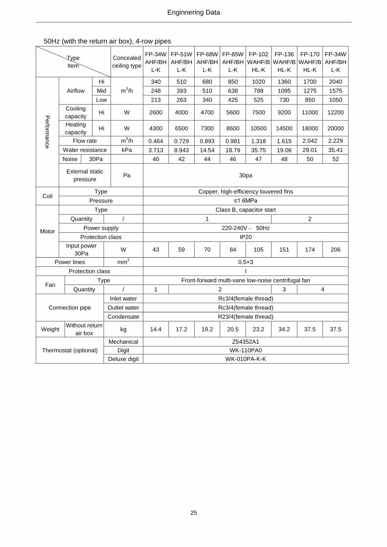
50Hz (with the return air box), 4-row pipes
Type
Item
Concealed
ceiling type
FP-34W
AHF/BH
L-K
FP-51W
AHF/BH
L-K
FP-68W
AHF/BH
L-K
FP-85W
AHF/BH
L-K
FP-102
WAHF/B
HL-K
FP-136
WAHF/B
HL-K
FP-170
WAHF/B
HL-K
FP-34W
AHF/BH
L-K
Pe
rform
an
ce
Airflow
Hi
m3/h
340 510 680 850 1020 1360 1700 2040
Mid 248 393 510 638 788 1095 1275 1575
Low 213 263 340 425 525 730 850 1050
Cooling
capacity Hi W 2600 4000 4700 5600 7500 9200 11000 12200
Heating
capacity Hi W 4300 6500 7300 8600 10500 14500 18000 20000
Flow rate m3/h 0.464 0.729 0.893 0.981 1.318 1.615 2.042 2.229
Water resistance kPa 3.713 8.943 14.54 18.79 35.75 19.06 29.01 35.41
Noise 30Pa
40 42 44 46 47 48 50 52
External static
pressure Pa 30pa
Coil Type Copper, high-efficiency louvered fins
Pressure ≤1.6MPa
Motor
Type Class B, capacitor start
Quantity / 1 2
Power supply 220-240V~ 50Hz
Protection class IP20
Input power
30Pa W 43 59 70 84 105 151 174 206
Power lines mm2 0.5×3
Protection class I
Fan Type Front-forward multi-vane low-noise centrifugal fan
Quantity / 1 2 3 4
Connection pipe
Inlet water Rc3/4(female thread)
Outlet water Rc3/4(female thread)
Condensate R23/4(female thread)
Weight Without return
air box kg 14.4 17.2 19.2 20.5 23.2 34.2 37.5 37.5
Thermostat (optional)
Mechanical Z54352A1
Digit WK-110PA0
Deluxe digit WK-010PA-K-K

Enginnering Data
26
50Hz (with the return air box), 3+1-row pipes
Type
Item
Concealed
ceiling type
FP-34W
AHT/BH
L-K
FP-51W
AHT/BH
L-K
FP-68W
AHT/BH
L-K
FP-85W
AHT/BH
L-K
FP-102
WAHT/B
HL-K
FP-136
WAHT/B
HL-K
FP-170
WAHT/B
HL-K
FP-204
WAHT/B
HL-K
Pe
rform
an
ce
Airflow
Hi
m3/h
340 510 680 850 1020 1360 1700 2040
Mid 248 393 510 638 788 1095 1275 1575
Low 213 263 340 425 525 730 850 1050
Cooling
capacity Hi W 2300 3600 4350 5400 6700 8100 10350 11000
Heating
capacity Hi W 2100 3350 4000 4600 5350 7000 8300 8950
Flow rate m3/h 0.446 0.697 0.808 0.98 1.171 1.45 1.747 1.964
Water resistance kPa 5.83 13.50 19.86 30.81 51.67 17.20 25.24 29.34
Noise 30Pa
40 42 44 46 47 48 50 52
External static
pressure Pa 30pa
Coil Type Copper, high-efficiency louvered fins
Pressure ≤1.6MPa
Motor
Type Class B, capacitor start
Quantity / 1 2
Power supply 220-240V~ 50Hz
Protection class IP20
Input power
30Pa W 43 59 70 84 105 151 174 206
Power lines mm2 0.5×3
Protection class I
Fan Type Front-forward multi-vane low-noise centrifugal fan
Quantity / 1 2 3 4
Connection pipe
Inlet water Rc3/4(female thread)
Outlet water Rc3/4(female thread)
Condensate R23/4(female thread)
Weight Without return
air box kg 14.4 17.2 19.2 20.5 23.2 34.2 37.5 37.5
Thermostat (optional)
Mechanical Z54352A1
Digit WK-110PA0
Deluxe digit WK-010PA-K-K
1.5.2 Temperature at Nominal Conditions
Item
Water Side Air Side
Entering water
temperature (℃)
Leaving water
temperature (℃)
DB Temperature
(℃) WB Temperature (℃)
Cooling 7
45
12 27 19.5
Heating 60 - 21 -
1.5.3 Operation Range
Item Water Side Air Side
Leaving water temperature (℃)
进出水温差(℃)
Environment DB Temperature (℃)
Cooling >5
2.5~6
16~40
Heating <80
2.5~6
10~35
Note: when conditions are out of the range, please contact GREE.
Enginnering Data
27
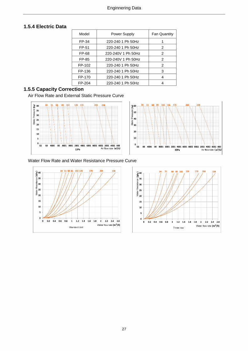
1.5.4 Electric Data
Model Power Supply Fan Quantity
FP-34 220-240 1 Ph 50Hz 1
FP-51 220-240 1 Ph 50Hz 2
FP-68 220-240V 1 Ph 50Hz 2
FP-85 220-240V 1 Ph 50Hz 2
FP-102 220-240 1 Ph 50Hz 2
FP-136 220-240 1 Ph 50Hz 3
FP-170 220-240 1 Ph 50Hz 4
FP-204 220-240 1 Ph 50Hz 4
1.5.5 Capacity Correction
Air Flow Rate and External Static Pressure Curve
Water Flow Rate and Water Resistance Pressure Curve

Enginnering Data
28
2. Dimensions of the Unit
Standard, 3-row pipes
Model
Legend FP-34 FP-51 FP-68 FP-85 FP-102 FP-136 FP-170 FP-204 FP-238
A 680 800 900 1000 1080 1380 1520 1620 1820
B 490 460 490 490 490 490 490 490 485
C 235 235 235 235 235 235 235 235 276
D 512 632 732 832 912 1212 1352 1452 1652
E 132 132 132 132 132 132 132 132 194
F 512 682 782 882 962 1262 1402 1502 1652
G 235 235 235 235 235 235 235 235 276
H 486 606 706 806 886 1186 1326 1426 1626
I 512 632 732 832 912 1212 1352 1452 1652
J 214 214 214 214 214 214 214 214 255
K 57 57 57 57 57 57 57 57 57
K for the extended drain tray is 300mm.

Enginnering Data
29
Standard, 3+1 or 4-row-pipes
F-T Series L a b F-T Series L a b
FP-34WAF(T)-R 490 45 310 FP-102WAF(T)-R 980 45 310
FP-51WAF(T)-R 620 45 310 FP-136WAF(T)-R 1400 75 250
FP-68WAF(T)-R 740 45 310 FP-170WAF(T)-R 1500 75 310
FP-85WAF(T)-R 820 45 310 FP-204WAF(T)-R 1500 75 310
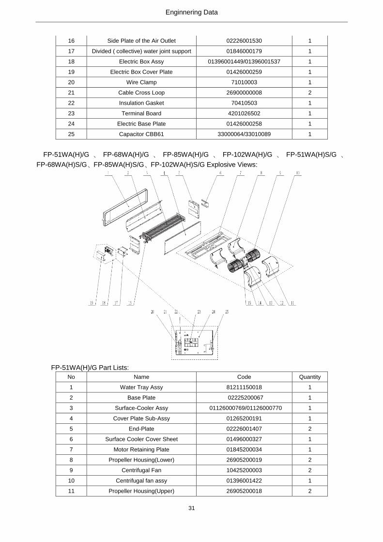
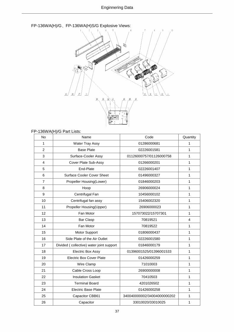
3. Explosive Views and Part Lists
FP-34WA(H)/G、FP-34WA(H)S/G Explosive Views:

Enginnering Data
30
FP-34WA(H)/G Part Lists:
No Name Code Quantity
1 Water Tray Assy 81211150017 1
2 Base Plate 02225200066 1
3 Surface-Cooler Assy 01126000766/01126000767 1
4 Cover Plate Sub-Assy 01265200190 1
5 End-Plate 02226001407 2
6 Surface Cooler Cover Sheet 01496000327 1
7 Motor Retaining Plate 01845200033 1
8 Propeller Housing(Lower) 26906000024 1
9 Centrifugal Fan 10456000102 1
10 Centrifugal fan assy 01396001421 1
11 Propeller Housing(Upper) 26906000023 1
12 Fan Motor 150195264/15707301 1
13 Hoop 70819521 4
14 Bar Clasp 70819522 1
15 Motor Support 01806000437 1
16 Side Plate of the Air Outlet 02226001530 1
17 Divided ( collective) water joint support 01846000179 1
18 Electric Box Assy 01396001537 1
19 Electric Box Cover Plate 01426000259 1
20 Wire Clamp 71010003 1
21 Cable Cross Loop 26900000008 2
22 Insulation Gasket 70410503 1
23 Terminal Board 4201026502 1
24 Electric Base Plate 01426000258 1
25 Capacitor CBB61 33010089 1
FP-34WA(H)S/G Part Lists:
No Name Code Quantity
1 Water Tray Assy 81211150017 1
2 Base Plate 02225200066 1
3 Surface-Cooler Assy 01126000741/01126000768 1
4 Cover Plate Sub-Assy 01265200190 1
5 End-Plate 02226001407 2
6 Surface Cooler Cover Sheet 01496000327 1
7 Motor Retaining Plate 01845200033 1
8 Propeller Housing(Lower) 26906000024 1
9 Centrifugal Fan 10456000102 1
10 Centrifugal fan assy 01396001421 1
11 Propeller Housing(Upper) 26906000023 1
12 Fan Motor 150195264/15707301 1
13 Hoop 70819521 4
14 Bar Clasp 70819522 1
15 Motor Support 01806000437 1
Enginnering Data
31
16 Side Plate of the Air Outlet 02226001530 1
17 Divided ( collective) water joint support 01846000179 1
18 Electric Box Assy 01396001449/01396001537 1
19 Electric Box Cover Plate 01426000259 1
20 Wire Clamp 71010003 1
21 Cable Cross Loop 26900000008 2
22 Insulation Gasket 70410503 1
23 Terminal Board 4201026502 1
24 Electric Base Plate 01426000258 1
25 Capacitor CBB61 33000064/33010089 1
FP-51WA(H)/G 、 FP-68WA(H)/G 、 FP-85WA(H)/G 、 FP-102WA(H)/G 、 FP-51WA(H)S/G 、
FP-68WA(H)S/G、FP-85WA(H)S/G、FP-102WA(H)S/G Explosive Views:
FP-51WA(H)/G Part Lists:
No Name Code Quantity
1 Water Tray Assy 81211150018 1
2 Base Plate 02225200067 1
3 Surface-Cooler Assy 01126000769/01126000770 1
4 Cover Plate Sub-Assy 01265200191 1
5 End-Plate 02226001407 2
6 Surface Cooler Cover Sheet 01496000327 1
7 Motor Retaining Plate 01845200034 1
8 Propeller Housing(Lower) 26905200019 2
9 Centrifugal Fan 10425200003 2
10 Centrifugal fan assy 01396001422 1
11 Propeller Housing(Upper) 26905200018 2
Enginnering Data
32
12 Fan Motor 15707302/157073021 1
13 Hoop 70819521 1
14 Bar Clasp 70818025 4
15 Motor Support 01805200144 1
16 Side Plate of the Air Outlet 02225200064 1
17 Divided ( collective) water joint support 01846000179 1
18 Electric Box Assy 01396001540 /01396001541 1
19 Electric Box Cover Plate 01426000259 1
20 Wire Clamp 71010003 1
21 Cable Cross Loop 26900000008 2
22 Insulation Gasket 70410503 1
23 Terminal Board 4201026502 1
24 Electric Base Plate 01426000258 1
25 Capacitor CBB61 33010089 /33010089 1
FP-68WA(H)/G Part Lists:
No Name Code Quantity
1 Water Tray Assy 81211150010 1
2 Base Plate 02226001409 1
3 Surface-Cooler Assy 01126000754/01126000775 1
4 Cover Plate Sub-Assy 02226001410 1
5 End-Plate 02226001407 2
6 Surface Cooler Cover Sheet 01496000327 1
7 Motor Retaining Plate 01846000180 1
8 Propeller Housing(Lower) 26906000024 1
9 Centrifugal Fan 10456000102 1
10 Centrifugal fan assy 15406002335 1
11 Propeller Housing(Upper) 26906000023 1
12 Fan Motor 15019523/15019523 1
13 Hoop 70819521 4
14 Bar Clasp 70819522 1
15 Motor Support 01806000437 1
16 Side Plate of the Air Outlet 01376000082 1
17 Divided ( collective) water joint support 01846000179 1
18 Electric Box Assy 01396001546/01396001547 1
19 Electric Box Cover Plate 01426000259 1
20 Wire Clamp 71010003 1
21 Cable Cross Loop 26900000008 1
22 Insulation Gasket 70410503 1
23 Terminal Board 4201026502 1
24 Electric Base Plate 01426000258 1
25 Capacitor CBB61 33010025/33010026 1
Enginnering Data
33
FP-85WA(H)/G Part Lists:
No Name Code Quantity
1 Water Tray Assy 81211150010 1
2 Base Plate 02226001409 1
3 Surface-Cooler Assy 01126000754/01126000775 1
4 Cover Plate Sub-Assy 02226001410 1
5 End-Plate 02226001407 1
6 Surface Cooler Cover Sheet 01496000327 1
7 Motor Retaining Plate 01846000180 1
8 Propeller Housing(Lower) 26906000024 1
9 Centrifugal Fan 10456000102 1
10 Centrifugal fan assy 15406002335 1
11 Propeller Housing(Upper) 26906000023 1
12 Fan Motor 15019523/15019523 1
13 Hoop 70819521 4
14 Bar Clasp 70819522 1
15 Motor Support 1806000437 1
16 Side Plate of the Air Outlet 01376000082 1
17 Divided ( collective) water joint support 1846000179 1
18 Electric Box Assy 01396001546/01396001547 1
19 Electric Box Cover Plate 1426000259 1
20 Wire Clamp 71010003 1
21 Cable Cross Loop 26900000008 1
22 Insulation Gasket 70410503 1
23 Terminal Board 4201026502 1
24 Electric Base Plate 1426000258 1
25 Capacitor CBB61 33010025/33010026 1
FP-102WA(H)/G Part Lists:
No Name Code Quantity
1 Water Tray Assy 81211150011 1
2 Base Plate 02226001420 1
3 Surface-Cooler Assy 01126000753/01126000755 1
4 Cover Plate Sub-Assy 01266000151 1
5 End-Plate 02226001407 2
6 Surface Cooler Cover Sheet 01496000327 1
7 Motor Retaining Plate 01846000186 1
8 Propeller Housing(Lower) 26906000024 2
9 Centrifugal Fan 10456000102 2
10 Centrifugal fan assy 15406002260 1
11 Propeller Housing(Upper) 26906000023 2
12 Fan Motor 157073024 1
13 Hoop 70819521 4
14 Bar Clasp 70819522 1
Enginnering Data
34
15 Motor Support 01806000437 1
16 Side Plate of the Air Outlet 02226001483 1
17 Divided ( collective) water joint support 01846000179 1
18 Electric Box Assy 01396001522/01396001523 1
19 Electric Box Cover Plate 01426000259 1
20 Wire Clamp 71010003 1
21 Cable Cross Loop 26900000008 1
22 Insulation Gasket 70410503 1
23 Terminal Board 4201026502 1
24 Electric Base Plate 01426000258 1
25 Capacitor CBB61 34004000000201/33010027 1
FP-51WA(H)S/G Part Lists:
No Name Code Quantity
1 Water Tray Assy 81211150018 1
2 Base Plate 02225200067 1
3 Surface-Cooler Assy 01126000748/01126000771 1
4 Cover Plate Sub-Assy 01265200191 1
5 End-Plate 02226001407 2
6 Surface Cooler Cover Sheet 01496000327 1
7 Motor Retaining Plate 01845200034 1
8 Propeller Housing(Lower) 26905200019 2
9 Centrifugal Fan 10425200003 2
10 Centrifugal fan assy 01396001422 1
11 Propeller Housing(Upper) 26905200018 2
12 Fan Motor 15707302/157073021 1
13 Hoop 70819521 1
14 Bar Clasp 70818025 4
15 Motor Support 01805200144 1
16 Side Plate of the Air Outlet 02225200064 1
17 Divided ( collective) water joint support 01846000179 1
18 Electric Box Assy 01396001481/01396001542 1
19 Electric Box Cover Plate 01426000259 1
20 Wire Clamp 71010003 1
21 Cable Cross Loop 26900000008 2
22 Insulation Gasket 70410503 1
23 Terminal Board 4201026502 1
24 Electric Base Plate 01426000258 1
25 Capacitor CBB61 340040000002/33000064 1

Enginnering Data
35
FP-68WA(H)S/G Part Lists:
No Name Code Quantity
1 Water Tray Assy 81211150010 1
2 Base Plate 02226001409 1
3 Surface-Cooler Assy 01126000656/01126000776 1
4 Cover Plate Sub-Assy 02226001410 1
5 End-Plate 02226001407 1
6 Surface Cooler Cover Sheet 01496000327 1
7 Motor Retaining Plate 01846000180 1
8 Propeller Housing(Lower) 26906000024 1
9 Centrifugal Fan 10456000102 1
10 Centrifugal fan assy 15406002254/15406002336 1
11 Propeller Housing(Upper) 26906000023 1
12 Fan Motor 157073022/15019523 1
13 Hoop 70819521 4
14 Bar Clasp 70819522 1
15 Motor Support 01806000437 1
16 Side Plate of the Air Outlet 01376000082 1
17 Divided ( collective) water joint support 01846000179 1
18 Electric Box Assy 01396001329/01396001548 1
19 Electric Box Cover Plate 01426000259 1
20 Wire Clamp 71010003 1
21 Cable Cross Loop 26900000008 1
22 Insulation Gasket 70410503 1
23 Terminal Board 4201026502 1
24 Electric Base Plate 01426000258 1
25 Capacitor CBB61 33010026/33010027 1
FP-85WA(H)S/G Part Lists:
No Name Code Quantity
1 Water Tray Assy 81211150010 1
2 Base Plate 02226001409 1
3 Surface-Cooler Assy 01126000656/01126000776 1
4 Cover Plate Sub-Assy 02226001410 1
5 End-Plate 02226001407 1
6 Surface Cooler Cover Sheet 01496000327 1
7 Motor Retaining Plate 01846000180 1
8 Propeller Housing(Lower) 26906000024 1
9 Centrifugal Fan 10456000102 1
10 Centrifugal fan assy 15406002254/15406002336 1
11 Propeller Housing(Upper) 26906000023 1
12 Fan Motor 157073022/15019523 1
13 Hoop 70819521 4
14 Bar Clasp 70819522 1

Enginnering Data
36
15 Motor Support 1806000437 1
16 Side Plate of the Air Outlet 1376000082 1
17 Divided ( collective) water joint support 1846000179 1
18 Electric Box Assy 01396001329/01396001548 1
19 Electric Box Cover Plate 1426000259 1
20 Wire Clamp 71010003 1
21 Cable Cross Loop 26900000008 1
22 Insulation Gasket 70410503 1
23 Terminal Board 4201026502 1
24 Electric Base Plate 1426000258 1
25 Capacitor CBB61 33010026/33010027 1
FP-102WA(H)S/G Part Lists:
No Name Code Quantity
1 Water Tray Assy 81211150011 1
2 Base Plate 02226001420 1
3 Surface-Cooler Assy 01126000657/01126000756 1
4 Cover Plate Sub-Assy 01266000151 1
5 End-Plate 02226001407 2
6 Surface Cooler Cover Sheet 01496000327 1
7 Motor Retaining Plate 01846000186 1
8 Propeller Housing(Lower) 26906000024 2
9 Centrifugal Fan 10456000102 2
10 Centrifugal fan assy 15406002260 1
11 Propeller Housing(Upper) 26906000023 2
12 Fan Motor 157073024 1
13 Hoop 70819521 4
14 Bar Clasp 70819522 1
15 Motor Support 01806000437 1
16 Side Plate of the Air Outlet 02226001483 1
17 Divided ( collective) water joint support 01846000179 1
18 Electric Box Assy 01396001329/01396001524 1
19 Electric Box Cover Plate 01426000259 1
20 Wire Clamp 71010003 1
21 Cable Cross Loop 26900000008 1
22 Insulation Gasket 70410503 1
23 Terminal Board 4201026502 1
24 Electric Base Plate 01426000258 1
25 Capacitor CBB61 33010026/33010027 1
Enginnering Data
37
FP-136WA(H)/G、FP-136WA(H)S/G Explosive Views:
FP-136WA(H)/G Part Lists:
No Name Code Quantity
1 Water Tray Assy 01286000681 1
2 Base Plate 02226001581 1
3 Surface-Cooler Assy 01126000757/01126000758 1
4 Cover Plate Sub-Assy 01266000201 1
5 End-Plate 02226001407 1
6 Surface Cooler Cover Sheet 01496000327 1
7 Propeller Housing(Lower) 01846000203 1
8 Hoop 26906000024 1
9 Centrifugal Fan 10456000102 1
10 Centrifugal fan assy 15406002320 1
11 Propeller Housing(Upper) 26906000023 1
12 Fan Motor 157073022/15707301 1
13 Bar Clasp 70819521 4
14 Fan Motor 70819522 1
15 Motor Support 01806000437 1
16 Side Plate of the Air Outlet 02226001580 1
17 Divided ( collective) water joint support 01846000179 1
18 Electric Box Assy 01396001525/01396001533 1
19 Electric Box Cover Plate 01426000259 1
20 Wire Clamp 71010003 1
21 Cable Cross Loop 26900000008 1
22 Insulation Gasket 70410503 1
23 Terminal Board 4201026502 1
24 Electric Base Plate 01426000258 1
25 Capacitor CBB61 340040000002/34004000000202 1
26 Capacitor 33010020/33010025 1

Enginnering Data
38
FP-136WA(H)S/G Part Lists:
No Name Code Quantity
1 Water Tray Assy 1286000681 1
2 Base Plate 02226001581 1
3 Surface-Cooler Assy 01126000747/01126000759 1
4 Cover Plate Sub-Assy 01266000201 1
5 End-Plate 02226001407 1
6 Surface Cooler Cover Sheet 01496000327 1
7 Propeller Housing(Lower) 01846000203 1
8 Hoop 26906000024 1
9 Centrifugal Fan 10456000102 1
10 Centrifugal fan assy 15406002320 1
11 Propeller Housing(Upper) 26906000023 1
12 Fan Motor 157073022/15707301 1
13 Bar Clasp 70819521 4
14 Fan Motor 70819522 1
15 Motor Support 01806000437 1
16 Side Plate of the Air Outlet 02226001580 1
17 Divided ( collective) water joint support 01846000179 1
18 Electric Box Assy 01396001480/01396001526 1
19 Electric Box Cover Plate 01426000259 1
20 Wire Clamp 71010003 1
21 Cable Cross Loop 26900000008 1
22 Insulation Gasket 70410503 1
23 Terminal Board 4201026502 1
24 Electric Base Plate 01426000258 1
25 Capacitor CBB61 33010025/33010027 1
26 Capacitor 340040000002/33010025 1

Enginnering Data
39
FP-170WA(H)/G、FP-204WA(H)/G、FP-238WA(H)/G、FP-170WA(H)S/G、FP-204WA(H)S/G、
FP-238WA(H)S/G Explosive Views:
FP-170WA(H)/G Part Lists:
No Name Code Quantity
1 Water Tray Assy 81211150021 1
2 Base Plate 02226001479 1
3 Surface-Cooler Assy 01126000760/01126000761 1
4 Cover Plate Sub-Assy 01266000176 1
5 End-Plate 02226001407 2
6 Surface Cooler Cover Sheet 01496000327 1
7 Motor Retaining Plate 01846000191 1
8 Propeller Housing(Lower) 26906000024 4
9 Centrifugal Fan 10456000102 4
10 Centrifugal fan assy 15406002345 1
11 Propeller Housing(Upper) 26906000023 4
12 Fan Motor 157073022/15019523 2
13 Hoop 70819521 2
14 Bar Clasp 70819522 8
15 Motor Support 01806000437 2
16 Side Plate of the Air Outlet 01376000091 1
17 Divided ( collective) water joint support 01846000179 1
18 Electric Box Assy 01396001528 1
19 Electric Box Cover Plate 01426000259 1
20 Wire Clamp 71010003 1
21 Cable Cross Loop 26900000008 2
22 Insulation Gasket 70410503 1

Enginnering Data
40
23 Terminal Board 4201026502 1
24 Electric Base Plate 01426000258 1
25 Capacitor CBB61 33010026/33010027 2
FP-204WA(H)/G Part Lists:
No Name Code Quantity
1 Water Tray Assy 81211150030 1
2 Base Plate 02226001590 1
3 Surface-Cooler Assy 01155200024/01126000765 1
4 Cover Plate Sub-Assy 01265200194 1
5 End-Plate 02226001407 2
6 Surface Cooler Cover Sheet 01496000327 1
7 Motor Retaining Plate 01265200194 1
8 Propeller Housing(Lower) 26906000024 4
9 Centrifugal Fan 10456000102 4
10 Centrifugal fan assy 15406002329 1
11 Propeller Housing(Upper) 26906000023 4
12 Fan Motor 157073024 2
13 Hoop 70819521 2
14 Bar Clasp 70819522 8
15 Motor Support 01806000437 2
16 Side Plate of the Air Outlet 02226001589 1
17 Divided ( collective) water joint support 01846000179 1
18 Electric Box Assy 01396001531/01396001532 1
19 Electric Box Cover Plate 01426000259 1
20 Wire Clamp 71010003 1
21 Cable Cross Loop 26900000008 2
22 Insulation Gasket 70410503 1
23 Terminal Board 4201026502 1
24 Electric Base Plate 01426000258 1
25 Capacitor CBB61 33010026/33010010 2
FP-170WA(H)S/G Part Lists:
No Name Code Quantity
1 Water Tray Assy 81211150021 1
2 Base Plate 02226001479 1
3 Surface-Cooler Assy 01126000750/01126000762 1
4 Cover Plate Sub-Assy 01266000176 1
5 End-Plate 02226001407 2
6 Surface Cooler Cover Sheet 01496000327 1
7 Motor Retaining Plate 01846000191 1
8 Propeller Housing(Lower) 26906000024 4
9 Centrifugal Fan 10456000102 4
10 Centrifugal fan assy 15406002345 1
11 Propeller Housing(Upper) 26906000023 4
Enginnering Data
41
12 Fan Motor 157073022/15019523 2
13 Hoop 70819521 2
14 Bar Clasp 70819522 8
15 Motor Support 01806000437 2
16 Side Plate of the Air Outlet 01376000091 1
17 Divided ( collective) water joint support 01846000179 1
18 Electric Box Assy 01396001528 1
19 Electric Box Cover Plate 01426000259 1
20 Wire Clamp 71010003 1
21 Cable Cross Loop 26900000008 2
22 Insulation Gasket 70410503 1
23 Terminal Board 4201026502 1
24 Electric Base Plate 01426000258 1
25 Capacitor CBB61 33010026/33010027 2
FP-204WA(H)S/G Part Lists:
No Name Code Quantity
1 Water Tray Assy 81211150030 1
2 Base Plate 02226001590 1
3 Surface-Cooler Assy 01155200024/01126000765 1
4 Cover Plate Sub-Assy 01265200194 1
5 End-Plate 02226001407 2
6 Surface Cooler Cover Sheet 01496000327 1
7 Motor Retaining Plate 01265200194 1
8 Propeller Housing(Lower) 26906000024 4
9 Centrifugal Fan 10456000102 4
10 Centrifugal fan assy 15406002329 1
11 Propeller Housing(Upper) 26906000023 4
12 Fan Motor 157073024 2
13 Hoop 70819521 2
14 Bar Clasp 70819522 8
15 Motor Support 01806000437 2
16 Side Plate of the Air Outlet 02226001589 1
17 Divided ( collective) water joint support 01846000179 1
18 Electric Box Assy 01396001531/01396001532 1
19 Electric Box Cover Plate 01426000259 1
20 Wire Clamp 71010003 1
21 Cable Cross Loop 26900000008 2
22 Insulation Gasket 70410503 1
23 Terminal Board 4201026502 1
24 Electric Base Plate 01426000258 1
25 Capacitor CBB61 33010026/33010010 2
Enginnering Data
42
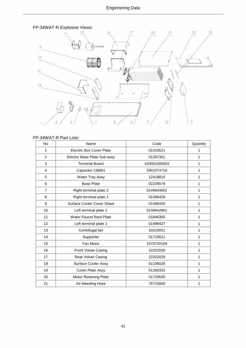
FP-34WAT-R Explosive Views:
FP-34WAT-R Part Lists:
No Name Code Quantity
1 Electric Box Cover Plate 01419521 1
2 Electric Base Plate Sub-assy 01287301 1
3 Terminal Board 420001000003 1
4 Capacitor CBB61 3301074716 1
5 Water Tray Assy 12418810 1
6 Base Plate 02226579 1
7 Right terminal plate 2 0149643001 1
8 Right terminal plate 1 01496429 1
9 Surface Cooler Cover Sheet 01496426 1
10 Left terminal plate 2 0149642801 1
11 Water Faucet fixed Plate 01846365 1
12 Left terminal plate 1 01496427 1
13 Centrifugal fan 10319051 1
14 Supporter 01719521 1
15 Fan Motor 1570730104 1
16 Front Volute Casing 22202030 1
17 Rear Volute Casing 22202029 1
18 Surface-Cooler Assy 01106026 1
19 Cover Plate Assy 01266332 1
20 Motor Retaining Plate 01729530 1
21 Air-bleeding Hose 76710060 1

Enginnering Data
43
FP-51WAT-R、FP-68WAT-R、FP-85WAT-R、FP-102WAT-R Explosive Views:
FP-51WAT-R Part Lists:
No Name Code Quantity
1 Electric Box Cover Plate 01419521 1
2 Electric Base Plate Sub-assy 01287301 1
3 Terminal Board 420001000003 1
4 Capacitor CBB61S 3301074702 1
5 Water Tray Assy 12418811 1
6 Base Plate 02226589 1
7 Right terminal plate 2 0149643001 1
8 Right terminal plate 1 01496429 1
9 Surface Cooler Cover Sheet 01496426 1
10 Left terminal plate 2 0149642801 1
11 Water Faucet fixed Plate 01846365 1
12 Left terminal plate 1 01496427 1
13 Centrifugal fan 10319051 2
14 Supporter 01719521 1
15 Fan Motor 1570730216 1
16 Front Volute Casing 22202030 2
17 Rear Volute Casing 22202029 2
18 Surface-Cooler Assy 0110602601 1
19 Cover Plate Assy 0126633201 1
20 Motor Retaining Plate 01729529 1
21 Air-bleeding Hose 76710060 1
FP-68WAT-R Part Lists:
No Name Code Quantity
1 Electric Box Cover Plate 01419521 1
2 Electric Base Plate Sub-assy 01287301 1
3 Terminal Board 420001000003 1
4 Capacitor CBB61S 3301074702 1

Enginnering Data
44
5 Water Tray Assy 12418813 1
6 Base Plate 02226588 1
7 Right terminal plate 2 0149643001 1
8 Right terminal plate 1 01496429 1
9 Surface Cooler Cover Sheet 01496426 1
10 Left terminal plate 2 0149642801 1
11 Water Faucet fixed Plate 01846365 1
12 Left terminal plate 1 01496427 1
13 Centrifugal fan 10319051 2
14 Supporter 01719521 1
15 Fan Motor 1570730216 1
16 Front Volute Casing 22202030 2
17 Rear Volute Casing 22202029 2
18 Surface-Cooler Assy 0110602602 1
19 Cover Plate Assy 0126633202 1
20 Motor Retaining Plate 01729527 1
21 Air-bleeding Hose 76710060 1
FP-85WAT-R Part Lists:
No Name Code Quantity
1 Electric Box Cover Plate 01419521 1
2 Electric Base Plate Sub-assy 01287301 1
3 Terminal Board 420001000003 1
4 Capacitor CBB61 3301074710 1
5 Water Tray Assy 12418814 1
6 Base Plate 02226587 1
7 Right terminal plate 2 0149643001 1
8 Right terminal plate 1 01496429 1
9 Surface Cooler Cover Sheet 01496426 1
10 Left terminal plate 2 0149642801 1
11 Water Faucet fixed Plate 01846365 1
12 Left terminal plate 1 01496427 1
13 Centrifugal fan 10319051 2
14 Supporter 01719521 1
15 Fan Motor 1570730220 1
16 Front Volute Casing 22202030 2
17 Rear Volute Casing 22202029 2
18 Surface-Cooler Assy 0110602603 1
19 Cover Plate Assy 0126633203 1
20 Motor Retaining Plate 01729526 1
21 Air-bleeding Hose 76710060 1

Enginnering Data
45
FP-102WAT-R Part Lists:
No Name Code Quantity
1 Electric Box Cover Plate 01419521 1
2 Electric Base Plate Sub-assy 01287301 1
3 Terminal Board 420001000003 1
4 Capacitor CBB61S 3301074705 1
5 Water Tray Assy 12418815 1
6 Base Plate 02226597 1
7 Right terminal plate 2 0149643001 1
8 Right terminal plate 1 01496429 1
9 Surface Cooler Cover Sheet 01496426 1
10 Left terminal plate 2 0149642801 1
11 Water Faucet fixed Plate 01846365 1
12 Left terminal plate 1 01496427 1
13 Centrifugal fan 10319051 2
14 Supporter 01719521 1
15 Fan Motor 1570730220 1
16 Front Volute Casing 22202030 2
17 Rear Volute Casing 22202029 2
18 Surface-Cooler Assy 0110602604 1
19 Cover Plate Assy 0126633204 1
20 Motor Retaining Plate 01729525 1
21 Air-bleeding Hose 76710060 1
FP-136WAT-R Explosive Views:

Enginnering Data
46
FP-136WAT-R Part Lists:
No Name Code Quantity
1 Surface Cooler Cover Sheet 0149642601 1
2 Right End-Plate Sub-Assy 1 01496440 1
3 Right End-Plate Sub-Assy 2 0149643901 1
4 Water Tray Assy 12418817 1
5 Base Plate 02226586 1
6 Surface-Cooler Assy 01106025 1
7 Cover Plate Assy 0126633205 1
8 Electric Base Plate Sub-assy 01287301 1
9 Terminal Board 420001000003 1
10 Capacitor CBB61S 3301074704 1
11 Air-bleeding Hose 76710060 2
12 Electric Box Cover Plate 01419521 1
13 Capacitor CBB61S 3301074701 1
14 Water Faucet fixed Plate 01846365 1
15 Left End-Plate Sub-Assy 2 0149644101 1
16 Left End-Plate Sub-Assy 1 01496442 1
17 Motor Retaining Plate 01749521 1
18 Rear Volute Casing 22202029 3
19 Centrifugal fan 10319051 3
20 Front Volute Casing 22202030 3
21 Fan Motor 1570730105 1
22 Supporter 01719521 2
23 Fan Motor 1570730220 1
FP-170WAT-R、FP-204WAT-R Explosive Views:
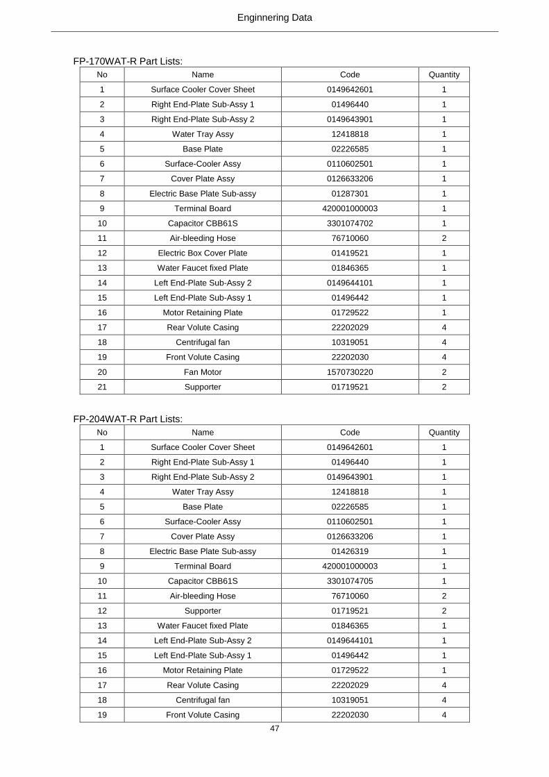
Enginnering Data
47
FP-170WAT-R Part Lists:
No Name Code Quantity
1 Surface Cooler Cover Sheet 0149642601 1
2 Right End-Plate Sub-Assy 1 01496440 1
3 Right End-Plate Sub-Assy 2 0149643901 1
4 Water Tray Assy 12418818 1
5 Base Plate 02226585 1
6 Surface-Cooler Assy 0110602501 1
7 Cover Plate Assy 0126633206 1
8 Electric Base Plate Sub-assy 01287301 1
9 Terminal Board 420001000003 1
10 Capacitor CBB61S 3301074702 1
11 Air-bleeding Hose 76710060 2
12 Electric Box Cover Plate 01419521 1
13 Water Faucet fixed Plate 01846365 1
14 Left End-Plate Sub-Assy 2 0149644101 1
15 Left End-Plate Sub-Assy 1 01496442 1
16 Motor Retaining Plate 01729522 1
17 Rear Volute Casing 22202029 4
18 Centrifugal fan 10319051 4
19 Front Volute Casing 22202030 4
20 Fan Motor 1570730220 2
21 Supporter 01719521 2
FP-204WAT-R Part Lists:
No Name Code Quantity
1 Surface Cooler Cover Sheet 0149642601 1
2 Right End-Plate Sub-Assy 1 01496440 1
3 Right End-Plate Sub-Assy 2 0149643901 1
4 Water Tray Assy 12418818 1
5 Base Plate 02226585 1
6 Surface-Cooler Assy 0110602501 1
7 Cover Plate Assy 0126633206 1
8 Electric Base Plate Sub-assy 01426319 1
9 Terminal Board 420001000003 1
10 Capacitor CBB61S 3301074705 1
11 Air-bleeding Hose 76710060 2
12 Supporter 01719521 2
13 Water Faucet fixed Plate 01846365 1
14 Left End-Plate Sub-Assy 2 0149644101 1
15 Left End-Plate Sub-Assy 1 01496442 1
16 Motor Retaining Plate 01729522 1
17 Rear Volute Casing 22202029 4
18 Centrifugal fan 10319051 4
19 Front Volute Casing 22202030 4

Enginnering Data
48
20 Fan Motor 1570730220 2
21 / / /
FP-34WAF-R Explosive Views:
FP-34WAF-R Part Lists:
No Name Code Quantity
1 Supporter 01719521 1
2 Fan Motor 1570730104 1
3 Rear Volute Casing 22202029 1
4 Front Volute Casing 22202030 1
5 Surface-Cooler Assy 01126395 1
6 Cover Plate Assy 01266332 1
7 Motor Retaining Plate 01729530 1
8 Air-bleeding Hose 76710060 1
9 Surface Cooler Cover Sheet 01496426 1
10 Right terminal plate 2 01496430 1
11 Right terminal plate 1 01496429 1
12 Base Plate 02226579 1
13 Water Tray Assy 12418810 1
14 Capacitor CBB61 3301074716 1
15 Terminal Board 420001000003 1
16 Electric Base Plate Sub-assy 01287301 1
17 Electric Box Cover Plate 01419521 1
18 Left terminal plate 2 01496428 1
19 Water Faucet fixed Plate 01847703 1
20 Left terminal plate 1 01496427 1
21 Centrifugal fan 10319051 1

Enginnering Data
49
FP-51WAF-R、FP-68WAF-R、FP-85WAF-R、FP-102WAF-R Explosive Views:
FP-51WAF-R Part Lists:
No Name Code Quantity
1 Supporter 01719521 1
2 Fan Motor 1570730216 1
3 Rear Volute Casing 22202029 2
4 Front Volute Casing 22202030 2
5 Surface-Cooler Assy 01126395 1
6 Cover Plate Assy 01266332 1
7 Motor Retaining Plate 01729529 1
8 Air-bleeding Hose 76710060 1
9 Surface Cooler Cover Sheet 01496426 1
10 Right terminal plate 2 01496430 1
11 Right terminal plate 1 01496429 1
12 Base Plate 02226589 1
13 Water Tray Assy 12418811 1
14 Capacitor CBB61S 3301074702 1
15 Terminal Board 420001000003 1
16 Electric Base Plate Sub-assy 01287301 1
17 Electric Box Cover Plate 01419521 1
18 Left terminal plate 2 01496428 1
19 Water Faucet fixed Plate 01847703 1
20 Left terminal plate 1 01496427 1
21 Centrifugal fan 10319051 2
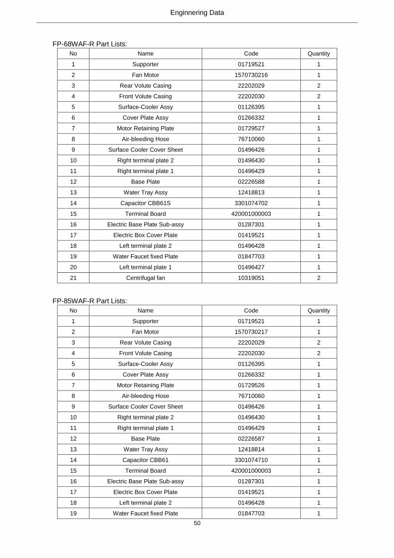
Enginnering Data
50
FP-68WAF-R Part Lists:
No Name Code Quantity
1 Supporter 01719521 1
2 Fan Motor 1570730216 1
3 Rear Volute Casing 22202029 2
4 Front Volute Casing 22202030 2
5 Surface-Cooler Assy 01126395 1
6 Cover Plate Assy 01266332 1
7 Motor Retaining Plate 01729527 1
8 Air-bleeding Hose 76710060 1
9 Surface Cooler Cover Sheet 01496426 1
10 Right terminal plate 2 01496430 1
11 Right terminal plate 1 01496429 1
12 Base Plate 02226588 1
13 Water Tray Assy 12418813 1
14 Capacitor CBB61S 3301074702 1
15 Terminal Board 420001000003 1
16 Electric Base Plate Sub-assy 01287301 1
17 Electric Box Cover Plate 01419521 1
18 Left terminal plate 2 01496428 1
19 Water Faucet fixed Plate 01847703 1
20 Left terminal plate 1 01496427 1
21 Centrifugal fan 10319051 2
FP-85WAF-R Part Lists:
No Name Code Quantity
1 Supporter 01719521 1
2 Fan Motor 1570730217 1
3 Rear Volute Casing 22202029 2
4 Front Volute Casing 22202030 2
5 Surface-Cooler Assy 01126395 1
6 Cover Plate Assy 01266332 1
7 Motor Retaining Plate 01729526 1
8 Air-bleeding Hose 76710060 1
9 Surface Cooler Cover Sheet 01496426 1
10 Right terminal plate 2 01496430 1
11 Right terminal plate 1 01496429 1
12 Base Plate 02226587 1
13 Water Tray Assy 12418814 1
14 Capacitor CBB61 3301074710 1
15 Terminal Board 420001000003 1
16 Electric Base Plate Sub-assy 01287301 1
17 Electric Box Cover Plate 01419521 1
18 Left terminal plate 2 01496428 1
19 Water Faucet fixed Plate 01847703 1

Enginnering Data
51
20 Left terminal plate 1 01496427 1
21 Centrifugal fan 10319051 2
FP-102WAF-R Part Lists:
No Name Code Quantity
1 Supporter 01719521 1
2 Fan Motor 1570730220 1
3 Rear Volute Casing 22202029 2
4 Front Volute Casing 22202030 2
5 Surface-Cooler Assy 01126395 1
6 Cover Plate Assy 01266332 1
7 Motor Retaining Plate 01729525 1
8 Air-bleeding Hose 76710060 1
9 Surface Cooler Cover Sheet 01496426 1
10 Right terminal plate 2 01496430 1
11 Right terminal plate 1 01496429 1
12 Base Plate 02226597 1
13 Water Tray Assy 12418815 1
14 Capacitor CBB61S 3301074705 1
15 Terminal Board 420001000003 1
16 Electric Base Plate Sub-assy 01287301 1
17 Electric Box Cover Plate 01419521 1
18 Left terminal plate 2 01496428 1
19 Water Faucet fixed Plate 01847703 1
20 Left terminal plate 1 01496427 1
21 Centrifugal fan 10319051 2
FP-136 WAF-R Explosive Views:

Enginnering Data
52
FP-136WAF-R Part Lists:
No Name Code Quantity
1 Surface Cooler Cover Sheet 0149642601 1
2 Right End-Plate Sub-Assy 1 01496440 1
3 Right End-Plate Sub-Assy 2 01496439 1
4 Base Plate 02226586 1
5 Surface-Cooler Assy 01126140 1
6 Water Tray Assy 12418817 1
7 Motor Retaining Plate 01749521 1
8 Left End-Plate Sub-Assy 1 01496442 1
9 Left End-Plate Sub-Assy 2 01496441 1
10 Water Faucet fixed Plate 0184770301 1
11 Capacitor CBB61S 3301074704 1
12 Terminal Board 420001000003 1
13 Electric Box Cover Plate 01419521 1
14 Capacitor CBB61S 3301074701 1
15 Electric Base Plate Sub-assy 01287301 1
16 Rear Volute Casing 22202029 3
17 Front Volute Casing 22202030 3
18 Cover Plate Assy 0126633205 1
19 Centrifugal fan 10319051 3
20 Fan Motor 1570730105 1
21 Fan Motor 1570730220 2
22 Supporter 01719521 2
23 Air-bleeding Hose 76710060 1
FP-170 WAF-R Explosive Views:

Enginnering Data
53
FP-170 WAF-R Part Lists:
No Name Code Quantity
1 Surface Cooler Cover Sheet 0149642601 1
2 Right End-Plate Sub-Assy 1 01496440 1
3 Right End-Plate Sub-Assy 2 01496439 1
4 Base Plate 02226585 1
5 Surface-Cooler Assy 01126140 1
6 Water Tray Assy 12418818 1
7 Motor Retaining Plate 01729522 1
8 Left End-Plate Sub-Assy 1 01496442 1
9 Left End-Plate Sub-Assy 2 01496441 1
10 Water Faucet fixed Plate 0184770301 1
11 Capacitor CBB61S 3301074702 1
12 Terminal Board 420001000003 1
13 Electric Box Cover Plate 01419521 1
14 Electric Base Plate Sub-assy 01287301 1
13 Rear Volute Casing 22202029 4
16 Front Volute Casing 22202030 4
17 Cover Plate Assy 0126633206 1
18 Centrifugal fan 10319051 4
29 Fan Motor 1570730220 4
20 Supporter 01719521 2
21 Air-bleeding Hose 76710060 1
FP-204 WAF-R Explosive Views:
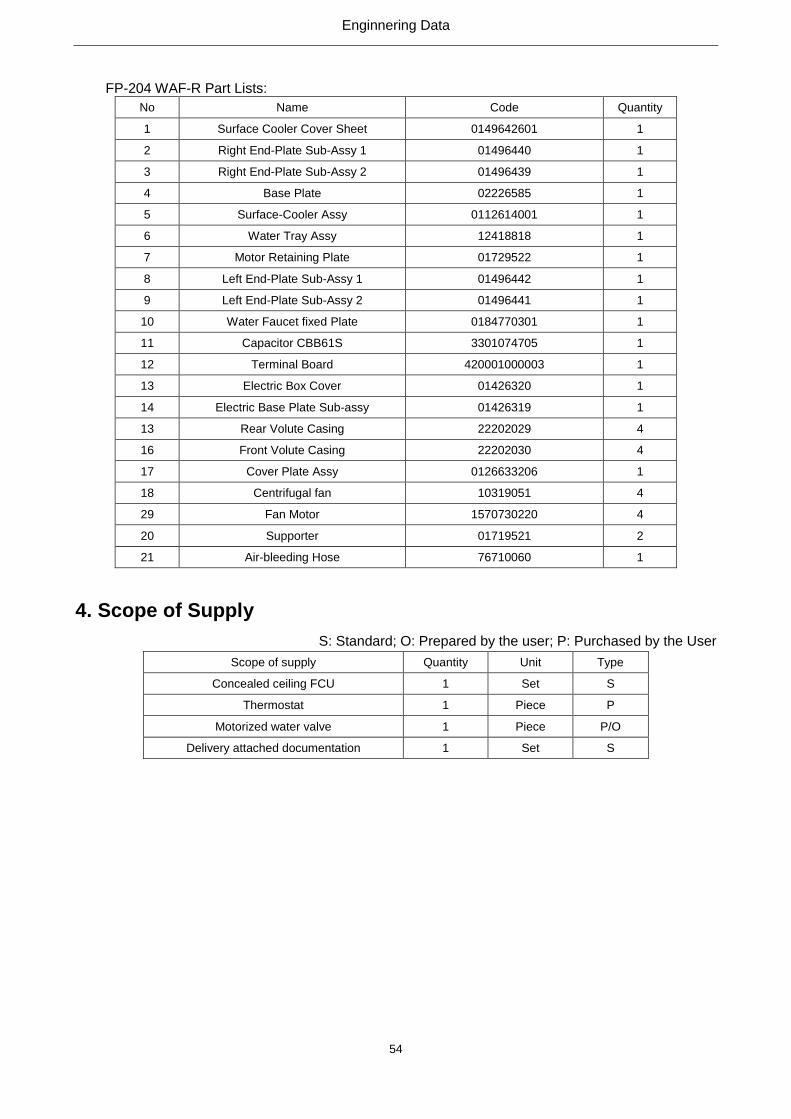
Enginnering Data
54
FP-204 WAF-R Part Lists:
No Name Code Quantity
1 Surface Cooler Cover Sheet 0149642601 1
2 Right End-Plate Sub-Assy 1 01496440 1
3 Right End-Plate Sub-Assy 2 01496439 1
4 Base Plate 02226585 1
5 Surface-Cooler Assy 0112614001 1
6 Water Tray Assy 12418818 1
7 Motor Retaining Plate 01729522 1
8 Left End-Plate Sub-Assy 1 01496442 1
9 Left End-Plate Sub-Assy 2 01496441 1
10 Water Faucet fixed Plate 0184770301 1
11 Capacitor CBB61S 3301074705 1
12 Terminal Board 420001000003 1
13 Electric Box Cover 01426320 1
14 Electric Base Plate Sub-assy 01426319 1
13 Rear Volute Casing 22202029 4
16 Front Volute Casing 22202030 4
17 Cover Plate Assy 0126633206 1
18 Centrifugal fan 10319051 4
29 Fan Motor 1570730220 4
20 Supporter 01719521 2
21 Air-bleeding Hose 76710060 1
4. Scope of Supply
S: Standard; O: Prepared by the user; P: Purchased by the User
Scope of supply Quantity Unit Type
Concealed ceiling FCU 1 Set S
Thermostat 1 Piece P
Motorized water valve 1 Piece P/O
Delivery attached documentation 1 Set S

Design & Selection
55
Design & Selection

Design & Selection
56
1. Selection Principle
1.1 Selection Steps
(1) Select the unit type based on the air flow, cooling capacity and heating capacity.
(2) Select the unit model based on the indoor cold/heat load, inlet air temperature, entering water
temperature and related data sheet. The cooling/heating capacity of the selected unit should be
or larger than the indoor cold/heat load.
(3) Take consideration of noise of the building.
(4) According to the allowable noise level of the corresponding building (see the next page for more
details), check if the selected unit can meet the noise requirement)
(5) Take hydraulic calculation to the duct system and then select the proper static pressure
1.2 Allowable Noise Level for Buildings
Type of Buildings A-weighted Sound Level (dBA)
Recording studio, broadcast studio, dubbing room 20~25
Concert hall, theatre, television studio 25~30
Cinema, lecture theatre, meeting room 30~35
Office room, design office, reading room, 35~40
Restaurant, banquet hall, gym, hotel 40~50
Waiting room, shopping center 45~55
Cleaning room, office room with mechanical
appliance 55~65
It is cited from Practical Design Manual of Heating Air Conditioning. If undesirable; reselect the unit
with lower noise.
1.3 Example for Selection
For a room of some hotel, the sensible heat cooling load is 3180W, and all heat cooling load is 4090W,
the inlet air dry bulb temperature is 27℃,the inlet air wet bulb temperature is 19.5℃, the air flow is
600m3/h, and the entering water temperature is 7℃. Based on these conditions, select a proper FCU.
See the following figure for the connection diagram of the FCU.

Design & Selection
57
Figure 1 Connection Diagram of the FCU
Step 1: select the unit type based on the air flow, cooling capacity and heating capacity.
a. Select the unit model based on the average cooling load.
b. Select the cooling capacity at the high air flow to meet the average cooling load.
c. Based on the inlet air 27℃/DB and 19.5℃ and entering water temperature 7℃, select from the
data sheet get a cooling capacity equal to larger than the cooling load.
d. When the cooling capacity is selected based on the medium or low speed air flow, then at
specific or load peak, use the high-speed for meeting the load demand.
e. For the model selected based on the cooling capacity, when the entering water temperature is
60℃, the water flow is the same as that for cooling and the heating capacity can meet the heat
load demand.
f. For the selected FP-85 based on the cooling capacity, the data sheet shows that its sensible
heat cooling capacity is 4160W, the water flow is 0.21L/s, water resistance is 30kPa, and the air
flow is 850m3/h.
g. When the entering water temperature is 60℃, the heating capacity is 700W, which meets the
load demand.
Step 2: Check the building noise
a. According to the table in Section 1.2, the allowable noise for the hotel is 40~50dB (A). The
design noise of the FP-85 is 42dBA and 44dBA for the FP-102, both of which can meet the
noise requirement.
Step 3: Select the external static pressure
a. Distribute the air flow for each duct and number them as shown in the figure below
b. Based on the air flow and size of the duct in the figure above, calculate the duct resistance in
accordance with the table below.
No.
Air
flow
(m3/h)
Duct
width
(mm)
Duct height
(mm)
Duct
length
(m) ν(m/s) △ Py(Pa) ξ △ Pj(Pa) △ Py+△ Pj(Pa) Remarks
1 1020 800 200 0 2.83 0 3 5.64 5.64 Diffuser
2 1020 600 150 1 3.15 0.52 0.21 1.25 1.77
Supply
air duct
3 510 600 150 2 1.57 0.3 0.1 0.15 0.45
4 510 600 150 2 1.57 0.3 0 0 0.3
5 510 250 250 0 2.27 0 1.28 3.95 3.95 Dissufer
Total 5 1.12 10.99 12.11

Design & Selection
58
According to the calculation results, the sum of the on-way resistance and the local resistance is:
The dynamic pressure of the diffuser is:
For FP-102WA, based on the air flow of 1020m3/h and the outlet side of 820mm*130mm, the air
speed at the air outlet is 4.95m/s.
The dynamic pressure is:
The required total external pressure is:
The required external static pressure is:
The designed external static pressure is 12Pa, which is approach to the required external static
pressure 13.2Pa. Therefore, the selection result is satisfactory.
When selecting units, the practice is to match the design sensible heat load with the required
sensible load. In most cases, there is enough latent heat for the coils to meet the design requirement.
(1) Power Lines
Model Power Supply Sectional Area (mm2)
FP-*WA/G-K
FP-*WAH/G-K
FP-*WAS/G-K
FP-*WAHS/G-K
220-240VAC 1Ph 50Hz 1
FP-*WA/G-D
FP-*WAH/G-D
FP-*WAS/G-D
FP-*WAHS/G-D
208-230VAC 1Ph 60Hz 1
FP-*WA/GHL-K
FP-*WAH/GHL-K
FP-*WAS/GHL-K
FP-*WAHS/GHL-K
220-240VAC 1Ph 50Hz 1
Note: “*” indicates the air flow between 34~204.
PaPP JL 11.12
PavPd 09.327.22.12
1
2
1 22
PavPdy 24.466.22.12
1
2
1 22
PaPPPP dJLYY 24.18)09.311.12(2.1)(2.1
PaPPPPP dydJLJY 2.13)24.409.311.12(2.1)(2.1
Unit Control
59
Unit Control
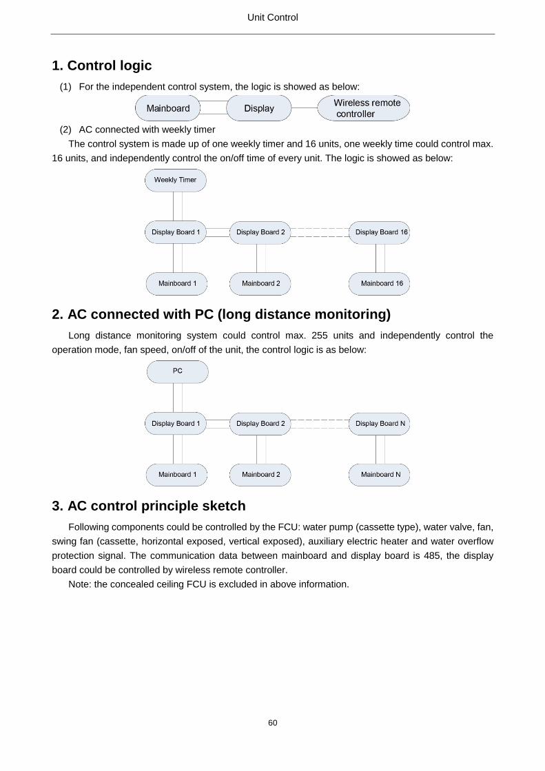
Unit Control
60
1. Control logic
(1) For the independent control system, the logic is showed as below:
(2) AC connected with weekly timer
The control system is made up of one weekly timer and 16 units, one weekly time could control max.
16 units, and independently control the on/off time of every unit. The logic is showed as below:
2. AC connected with PC (long distance monitoring)
Long distance monitoring system could control max. 255 units and independently control the
operation mode, fan speed, on/off of the unit, the control logic is as below:
3. AC control principle sketch
Following components could be controlled by the FCU: water pump (cassette type), water valve, fan,
swing fan (cassette, horizontal exposed, vertical exposed), auxiliary electric heater and water overflow
protection signal. The communication data between mainboard and display board is 485, the display
board could be controlled by wireless remote controller.
Note: the concealed ceiling FCU is excluded in above information.

Unit Installation
61
Unit Installation

Unit Installation
62
1. Preparation before Installation
1.1 Tools
(1) General electric tools
Hand-held electric drill
Usage: it is used for drilling holes at metals, wood or plastics etc.
Cutter
Usage: the fiber-reinforced sheet wheel can cut the round or special shaped steel pipes, cast iron
pipes, channel steel, and flat steel etc.
Grinding machine
Usage: the fiber-reinforced line-shaped wheel can grind metal pieces and cut sectional materials.
Before welding, a groove should be made, and fins and burrs of the work piece should be removed.
Equipped with the diamond cut sheet, it can cut the non-metallic materials, like ceramic tiles, stones etc.
Equipped with the special wheel, it can be used for cutting glass. Equipped with the wire brush, it can be
used for de-rusting. Equipped with the rubber pad and sand paper, it can be used for polishing.
Electric Hammer
Usage: equipped with the rigid alloy drilling bit, it is used for holes and grooves drilling and dabbing
at the concrete, the stone, bricks etc.
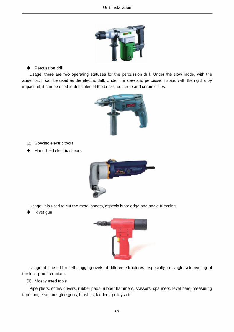
Unit Installation
63
Percussion drill
Usage: there are two operating statuses for the percussion drill. Under the slow mode, with the
auger bit, it can be used as the electric drill. Under the slew and percussion state, with the rigid alloy
impact bit, it can be used to drill holes at the bricks, concrete and ceramic tiles.
(2) Specific electric tools
Hand-held electric shears
Usage: it is used to cut the metal sheets, especially for edge and angle trimming.
Rivet gun
Usage: it is used for self-plugging rivets at different structures, especially for single-side riveting of
the leak-proof structure.
(3) Mostly used tools
Pipe pliers, screw drivers, rubber pads, rubber hammers, scissors, spanners, level bars, measuring
tape, angle square, glue guns, brushes, ladders, pulleys etc.

Unit Installation
64
1.2 Materials
Pipes
The condensate pipe is generally the U-PVC pipe, connected with the special glue. Besides, PP-R
pipes, PP-C pipes and galvanized steel pipes also are selectable, which all are with thread connectors.
Sheets
Sheets are main materials for ducts, including the galvanized steel sheets, mild steel sheets, and
aluminum sheets etc.
Galvanized sheets
The galvanized sheet steel is made the general steel sheet Q195 or Q235A coated with zinc.
Generally it is 0.5~1.5mm thick. No paint is required as its coating is corrosion-proof. It is widely used for
the duct system under the moisture environment without acid mist.
See the table for the thickness of the galvanized steel sheets, unless there is special requirement
on the thickness.
Diameter of the round duct or the larger side of the
rectangular duct(mm)
Thickness(mm)
General duct Return/exhaust duct
δ≤320
320<δ≤450
450<δ≤630
630<δ≤1000
1000<δ≤1250
1250<δ≤2000
2000<δ≤4000
0.5
0.6
0.6
0.75
1.0
1.0
1.2
0.6
0.75
0.75
1.0
1.2
As designed
As designed

Unit Installation
65
Mild steel sheets
It is the cold or hot rolled Q235-B(GB700-1988) steel sheet. It is of excellent plasticity and
processability. It can be easily welded, but it is likely to rust. Therefore, paint is required for corrosion
protection.
Stainless steel plate
The stainless steel sheet contains chlorine, nickel, and copper. It is high-temperature resistant and
corrosion-proof. Its surface is white. As alloying elements contained in the stainless steel sheet are
different, so corrosion resistance to different mediums varies. It can be widely used for the duct
system under the corrosive chemical environment.
Aluminum plate
It is classified into the pure aluminum plate and the aluminum alloy. Its specific weight is small.
There is an aluminum oxide film covered at the surface. It is of excellent plasticity and acid resistance,
but it is vulnerable to be corroded by alkalis and salts. It is generally used for the ventilation ducts
under the acid environment. As the aluminum plate is quite soft, it would generate sparks upon
collision. Therefore, it is mostly used for the ventilation duct with explosion-proof requirements.
1.3 Drain Hose

Unit Installation
66
Transparent drain hose should be selected so that it is able to clearly see the flow status. Length of
the drain hose is generally about 150mm. The hose should be connected to the unit and the drain pipe
by the pipe clamps for further maintenance but not by glue. Besides, the drain house should be
anti-shock.
1.4 Insulation
The insulation is used for thermal insulation. The mostly used insulation is loose fiber and porous
material. For FCU, the mostly used insulation is PEF and foam rubber.
PEF foam plastic
Using the advanced foaming technology, it is soft, light-weighted, fire-proof, and corrosion-proof. It
can be widely applicable to insulation for buildings, cold storages, air conditionings and low-temperature
pipes. Its operation is easy and simple.
Foam Rubber
It is mainly made of buna-n rubber and PVC. It is a high-foaming closed-cell elastic body, with small
density, low thermal conductivity coefficient, good weatherability, shock-absorbed, noise-absorbing,
flame-retardant and water-proof. Besides, its temperature range is wide, and no pollutant would be
generated during production and use. It is an environment friendly product.
Condensate pipe Insulation thickness Materials
Various diameter sizes ≥15 B1 or above nonflammable rubber foam
pipe The thickness should be enlarged when it is used under moisture
environment.
(1) Hangers and Supporters
a. Hanger: M8 or M10
b. Channel steel: #14 or above
c. Angle steel: 30mm×30mm×3mm or above
d. Round steel: above Φ10mm

Unit Installation
67
(2) Power lines
Type and size of the power lines should meet relative design regulations. When there is no specific
regulation, the minimal sectional area of the conduct cores under different laying mode should refer to
the user’s manual of the FCU.
(3) Anti-corrosion materials
The commonly used anti-corrosion materials include paint, resin and asphalt etc.
2. Installation
2.1 Precautions for Installation
(1) The unit should be installed in accordance with instructions covered in the user’s manual and
make sure enough maintenance space is reserved around the unit. The air inlet and outlet should
be far away from obstacles, so that air flow can go through everywhere of the room. When the
heat exchanging room is too small, it would lead to decreased capacity.
(2) The unit should be installed where there is smog, corrosive and inflammable gases, otherwise the
unit would fail to run normally or its service life would be shortened.
(3) The supply air outlets, return air inlets, ducts and diffusers should be arranged properly so that
the supply air flow will be even and smooth. For where there is high requirement on noise, back
return air should be adopted rather than downward return air, like offices, guest rooms of the
hotels, wards of hospitals. Insulation can be used for ducts to reduce noise.
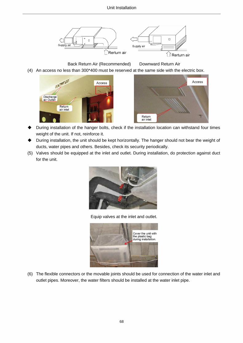
Unit Installation
68
Back Return Air (Recommended) Downward Return Air
(4) An access no less than 300*400 must be reserved at the same side with the electric box.
During installation of the hanger bolts, check if the installation location can withstand four times
weight of the unit. If not, reinforce it.
During installation, the unit should be kept horizontally. The hanger should not bear the weight of
ducts, water pipes and others. Besides, check its security periodically.
(5) Valves should be equipped at the inlet and outlet. During installation, do protection against duct
for the unit.
Equip valves at the inlet and outlet.
(6) The flexible connectors or the movable joints should be used for connection of the water inlet and
outlet pipes. Moreover, the water filters should be installed at the water inlet pipe.

Unit Installation
69
(7) Teflon tape should be used for connection of the inlet and outlet pipes. No leak is allowed.
(8) Pipes should be insulated to prevent from generating condensate.
(9) The condensate pipe should not be blocked with a grade of slope no less than 5%.
(10) A filter should be installed at the return air inlet and cleaned periodically so as to not affect the
heat exchanging efficiency.
(11) For initial operation, open the exhaust valve at the return water pipe to expel air inside coils. Then,
close it until water flows out.
(12) Temperature of the cold water should not be lower than 5℃ and not higher than 70℃ for hot
water. Water should be clean. The unit should be entirely maintained every 2~3 years. Water
scale inside coils should be removed by chemical method so as to guarantee the heat exchanging
performance.
(13) The air outlet and the duct should be connected with the flexible connector and shall not bear the
weight of valves, pipes and other devices.
(14) Wiring arrangement should be performed in accordance with the safety standards for electric
devices and local relative regulations. Special electric circuits should be used. When capacity of
the electric circuits is poor or electric operation is improper, it would lead to electric shocks or fire
hazards etc.
(15) The earth leakage circuit breaker should be installed for each installation location. The unit should
be grounded; otherwise it would lead to electric shocks.

Unit Installation
70
2.2 Installation Steps

Test Operation & Troubleshooting & Maintenance
71
Test Operation & Troubleshooting &
Maintenance

Test Operation & Troubleshooting & Maintenance
72
1. Error List
No. Error Possible Causes Solutions
1 Air leak There is a joint seam between metal sheets.
There is deformation caused by poor installation.
Seal the joint seam.
Adjust the installation location.
2 Water leak
Too large air flow leads to water splashing.
Insulation under the drain pan is poor and
condensate is generated.
Adjust the air flow.
Install the drain pipe.
Improve the insulation.
3 Dewing Insulation of the metal sheets poor and cold
bridges exist. Improve the insulation.
4 Poor drainage The drain pan is deformed.
There is no slope degree.
Correct the drain pan.
Adjust the hanger to incline the drain
outlet.
5 Abnormal
operation
The fan blades contact the housing.
There are foreign matters.
Adjust the fan blades.
Remove them.
6 Too large air flow Resistance of the duct is too small (the duct is
too short) Adjust the air flow.
7 Too small air flow
Coils or the filter screens are too dirty.
Resistance of the duct is too large (the duct is
too long)
Clean or replace them.
Adjust the air flow.
8 Poor cooling
capacity
Air is trapped inside the system.
Coils or the filter screens are too dirty.
Open the exhaust valve to expel air
Clean or replace them
9 Burnt motor The motor is overloaded
The motor
Adjust the air flow and replace the
motor
Replace the motor
Replace the motor
2. Electric Diagrams
FP-34WA(H)/G; FP-51WA(H)/G; FP-68WA(H)/G; FP-85WA(H)/G; FP102WA(H)/G;FP-136WA(H)/G;
FP- 170WA(H)/G; FP-204WA(H)/G; FP-238WA(H)/G; FP-34WA(H)S/G; FP-51WA(H)S/G;
FP-68WA(H)S/G; FP- 85WA(H)S/G; FP102WA(H)S/G
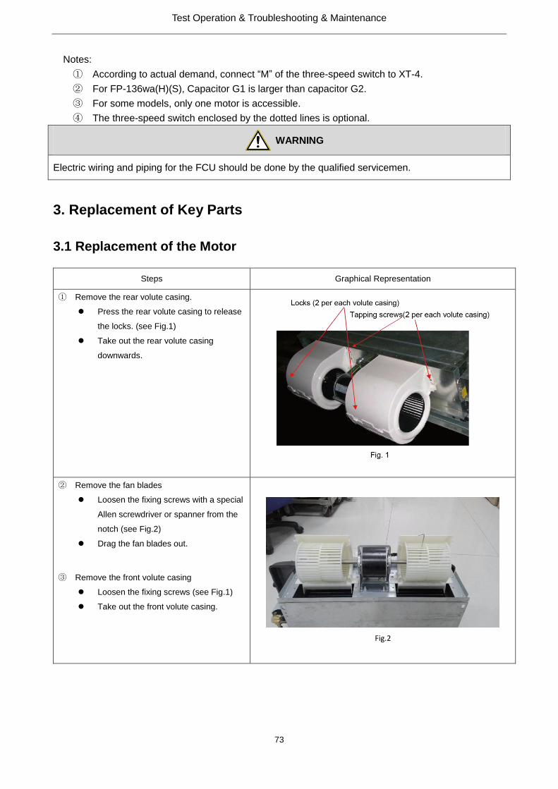
Test Operation & Troubleshooting & Maintenance
73
Notes:
① According to actual demand, connect “M” of the three-speed switch to XT-4.
② For FP-136wa(H)(S), Capacitor G1 is larger than capacitor G2.
③ For some models, only one motor is accessible.
④ The three-speed switch enclosed by the dotted lines is optional.
WARNING
Electric wiring and piping for the FCU should be done by the qualified servicemen.
3. Replacement of Key Parts
3.1 Replacement of the Motor
Steps Graphical Representation
① Remove the rear volute casing.
Press the rear volute casing to release
the locks. (see Fig.1)
Take out the rear volute casing
downwards.
② Remove the fan blades
Loosen the fixing screws with a special
Allen screwdriver or spanner from the
notch (see Fig.2)
Drag the fan blades out.
③ Remove the front volute casing
Loosen the fixing screws (see Fig.1)
Take out the front volute casing.
Fig.2

Test Operation & Troubleshooting & Maintenance
74
④ Remove the motor
Loosen the fixing screws on the motor
and remove the clamping band and the
hoop (see Fig.3)
Loosen the grounding screws and
disconnect the ground wire.
Loosen the screws on the electric box
and remove the cover plate of it.
Remove the connecting inserter of
motor from the terminal board of the
electric box and the capacitor.
Cut the tie wire, disconnect the
connection wire, and take out the
motor.
3.2 Replacement of the Cooler
Steps Graphical Representation
① Remove the mounted plate of the liquid
distributor
Take out the cove plate of the electric
box (see Fig 3)
Loosen one fixing screw on the
soleplate of the electric box (see
Fig.4)
Turn the soleplate of the electric box.
Loosen fixing screws on the mounted
plate.
Loosen tapping screws on the
mounted plate
Take out the mounted plate
Fig.4

Test Operation & Troubleshooting & Maintenance
75
② Remove the cover plate
Loosen the tapping screws on the
cover plate and other relative
components (see Fig.5).
Take out the cover plate.
Fig 5
③ Remove the cooler.
Loosen the taping screws on the side
plate (see Fig.6)
Loosen the taping screws on the end
sides
Take out the end plates
Take out the cooler upwards.
Tapping screws (total 14 pieces)
Fig.6
4. Explosive Views and Part List
◆ FP-34WA(H)/G, FP-34WA(H)S/G
◆ FP-51WA(H)/G, FP-68WA(H)/G, FP-85WA(H)/G, FP-102WA(H)/G, FP-51WA(H)S/G 、
FP-68WA(H)S/G, P-85WA(H)S/G, FP-102WA(H)S/G
◆ FP-136WA(H)/G, FP-136WA(H)S/G
◆ FP-170WA(H)/G, FP-204WA(H)/G, FP-238WA(H)/G, FP-170WA(H)S/G, FP-204WA(H)S/G、
FP-238WA(H) S/G