
Computer Simulation on Injection Molding Process of ...
6
Computer Simulation on Injection Molding Process of Automotive Engine Air intake Manifold Based on Moldflow Hanwu Liu a , Jiao Zhang b , Yang Wang c , Junming Liu School of Mechanical and Electrical Engineering, North China Institute of Science and Technology, Sanhe, Hebei, 065201, China a [email protected], b [email protected], c [email protected] Keywords: Intake Manifold; Injection Molding Process; Flow Analysis; Quality Defects; Temperature Distribution Abstract. Engineering plastics with its unique performance advantages in automobile manufacture is becoming more widespread. Plastic intake manifold of the engine intake system as the most critical components of its design and manufacture great difficulty, its injection molding process is crucial to the design of their molding mold. In this paper, the use of Pro/E three-dimensional modeling software for the intake manifold parts diagram of the three-dimensional design, in this format stl Import part drawings into finite element analysis software Moldflow, Moldflow software reuse plastic intake manifold injection molding when the gating system, product temperature, volume contraction, solidification sequence and time and products deformation were analyzed and designed to optimize the forming process parameters, gating system and cooling system, it predicted that may occur during the injection molding process, each kinds of defects and deficiencies. The results can be extended to other similar components design, which has a strong engineering application. Introduction In order to meet the automotive industry, "high-speed, energy saving, high comfort level" of development, automotive parts materials must have a greater change, wherein the polymeric material (such as plastic, plastic, rubber, thermoplastic elastomers, fibers) and its composite material with its unique advantages will be more widely used in the automotive industry. Automotive engine air intake manifold of the engine intake system is the most important part, provide a sufficiently uniform mixture to each cylinder of the engine, the intake efficiency of the engine determines the uniformity and various pneumatic cylinders, but also for the main engine electronic injection system sensors and actuators to provide structural support. Due to the complex structure of the intake manifold, most current intake manifold is made of aluminum alloy by sand casting mold manufacturing process. Since the process conditions by aluminum intake manifold and an inner wall surface roughness, large inflatable resistance, high quality, and even left sand holes, pores, resistance to air when using noise are large, resulting enter combustion air swirl, affecting volumetric efficiency and combustion quality, combustion is not sufficient, more emissions. Further, since the high thermal conductivity of aluminum alloy, aluminum intake manifold of the engine by heat transfer, so that the intake manifold to reduce the density of the air expansion, reduce the amount of air required for combustion of a direct impact on engine efficiency, it has seriously affected the car energy saving and environmental effects. In order to achieve weight reduction, reduce fuel consumption, improve engine performance and reduce emissions, etc. We must study and develop a new type of engine intake manifold. Pultrusion is a typical process for manufacturing GFRP continuously and economically with maPlastic intake manifold for its light weight and inexpensive, high-performance advantages are gradually replacing metal intake manifold, its performance in the future development must continue to improve in order to meet the increasingly demanding engine environments. Development and production of China's national conditions needed to shorten new product development cycles, reduce costs, energy saving, beautiful and durable automotive intake manifold injection mold 2nd International Conference on Electronics, Network and Computer Engineering (ICENCE 2016) © 2016. The authors - Published by Atlantis Press 359
Transcript of Computer Simulation on Injection Molding Process of ...

Computer Simulation on Injection Molding Process of Automotive Engine Air intake Manifold Based on Moldflow
Hanwu Liua, Jiao Zhangb, Yang Wangc, Junming Liu School of Mechanical and Electrical Engineering, North China Institute of Science and Technology,
Sanhe, Hebei, 065201, China [email protected], [email protected], [email protected]
Keywords: Intake Manifold; Injection Molding Process; Flow Analysis; Quality Defects; Temperature Distribution
Abstract. Engineering plastics with its unique performance advantages in automobile manufacture is becoming more widespread. Plastic intake manifold of the engine intake system as the most critical components of its design and manufacture great difficulty, its injection molding process is crucial to the design of their molding mold. In this paper, the use of Pro/E three-dimensional modeling software for the intake manifold parts diagram of the three-dimensional design, in this format stl Import part drawings into finite element analysis software Moldflow, Moldflow software reuse plastic intake manifold injection molding when the gating system, product temperature, volume contraction, solidification sequence and time and products deformation were analyzed and designed to optimize the forming process parameters, gating system and cooling system, it predicted that may occur during the injection molding process, each kinds of defects and deficiencies. The results can be extended to other similar components design, which has a strong engineering application.
Introduction In order to meet the automotive industry, "high-speed, energy saving, high comfort level" of
development, automotive parts materials must have a greater change, wherein the polymeric material (such as plastic, plastic, rubber, thermoplastic elastomers, fibers) and its composite material with its unique advantages will be more widely used in the automotive industry. Automotive engine air intake manifold of the engine intake system is the most important part, provide a sufficiently uniform mixture to each cylinder of the engine, the intake efficiency of the engine determines the uniformity and various pneumatic cylinders, but also for the main engine electronic injection system sensors and actuators to provide structural support.
Due to the complex structure of the intake manifold, most current intake manifold is made of aluminum alloy by sand casting mold manufacturing process. Since the process conditions by aluminum intake manifold and an inner wall surface roughness, large inflatable resistance, high quality, and even left sand holes, pores, resistance to air when using noise are large, resulting enter combustion air swirl, affecting volumetric efficiency and combustion quality, combustion is not sufficient, more emissions. Further, since the high thermal conductivity of aluminum alloy, aluminum intake manifold of the engine by heat transfer, so that the intake manifold to reduce the density of the air expansion, reduce the amount of air required for combustion of a direct impact on engine efficiency, it has seriously affected the car energy saving and environmental effects. In order to achieve weight reduction, reduce fuel consumption, improve engine performance and reduce emissions, etc. We must study and develop a new type of engine intake manifold.
Pultrusion is a typical process for manufacturing GFRP continuously and economically with maPlastic intake manifold for its light weight and inexpensive, high-performance advantages are gradually replacing metal intake manifold, its performance in the future development must continue to improve in order to meet the increasingly demanding engine environments. Development and production of China's national conditions needed to shorten new product development cycles, reduce costs, energy saving, beautiful and durable automotive intake manifold injection mold
2nd International Conference on Electronics, Network and Computer Engineering (ICENCE 2016)
© 2016. The authors - Published by Atlantis Press 359

tooling, molding process, get rid of foreign companies on the domestic market of technical monopoly, the development of China's automobile intake manifold injection molding of independent innovation, improve the core competitiveness of products has important strategic significance. In this paper, finite element analysis software Moldflow plastic automobile engine intake manifold to simulate the injection molding process, the injection molding process to predict product defects, in order to suggest improvements as soon as possible.
Analysis and Simulation of Intake Manifold Injection Molding Process Currently plastic intake manifold materials mainly nylon (PA)/glass fiber (GF) composites. This
material not only has good mechanical properties, self-lubricating, wear resistance, chemical resistance, oil resistance and gas barrier properties, but also non-toxic, easy to color and so on. This paper uses a Generic PA66 (Leona), namely PA66 + 30% Glass Fiber. Three-dimensional model and style divided view of the plastic intake manifold shown in Fig. 1 and Fig. 2 respectively.
Gating system design and determine the best gate location. Gate location directly affects the gate filling model determines the melt flow direction and balance. When the flow imbalance is likely to cause uneven shrinkage and warpage, weld marks and bubbles and affect the quality of the internal stress and orientation of parts. Inappropriate gate location is often caused by the gas can not escape the cavity during the injection molding process, resulting in a short shot, cavitation, scorch defects such as injection molding, and therefore a reasonable choice of gate location is very important in the mold design. The use of software in the module gate location analysis to identify reasonable gate location shown in Fig. 3. Because this product is bent tube, using a little when poured into the injection pressure is high, likely to cause excessive plastic molecular orientation and
Fig. 1 3-D model of the intake manifold Fig. 2 Finite Element model of the Intake
Fig. 3 Best Gate Location Analysis Chart Fig. 4 Gating System Diagram
360

residual stress and thus exacerbate the warpage of products, therefore, the product is poured into two. Gating system shown in Fig. 4. After creating the gating system, you should check the connectivity of the cavity and gating system. By looking at the cavity connectivity analysis module, the communication part found all in blue, indicating that connectivity is very good system.
Velocity pressure/pressure switch. Pressure case article velocity / pressure when switching to 28.36MPa, speed control is to control the maximum pressure injection pressure value conversion. As can be seen from Fig. 5, the molten plastic to fill the V / P conversion occurs when the junction of dark blue area and the gray area. All currently charging portion, which is the colored part, are completed filling in speed control. Multi-pressure can be set according to the pressure output V / P point conversion to injection molding machines provide valuable reference.
Volume shrinkage. Uniform volumetric shrinkage products to avoid excessive warping occurs; when the article overall shrinkage difference is small, the article mold cavity to substantially shrink the size of shrinkage, warpage amount is very small. Article volumetric shrinkage and sink marks corresponding to the index, a large part of the value of shrinkage volume shrinkage prone, as shown in Fig. 6. In order to obtain comparative average shrinkage value, should pay attention to the filling of the gate balance and uniformity of the article as a whole is cooled, if allowed to modify the products at the local flesh is too thick.
Frozen layer factor. Frozen layer factor for viewing articles and gate freeze sequence and set time, it is possible according to the results set packing. Gate solidification rate is not too fast, so that products can be fully dwell. Plenty of time to eliminate feeding products shrink, improve warpage. The gate can not clotting too late, otherwise after cutting packing pressure, will produce plastic cavity reflux, the article will also shrink, so packing useless. More can not be solidified gate too early, when the molten plastic will begin to set the volume shrinks, the gate if the time has been solidified, then fill the cavity can not get enough of shrink plastic, the article has not been
Fig. 5 Pressure Change in Speed / Pressure Switch
Fig. 6 Volume Shrinkage Variation Diagram
361
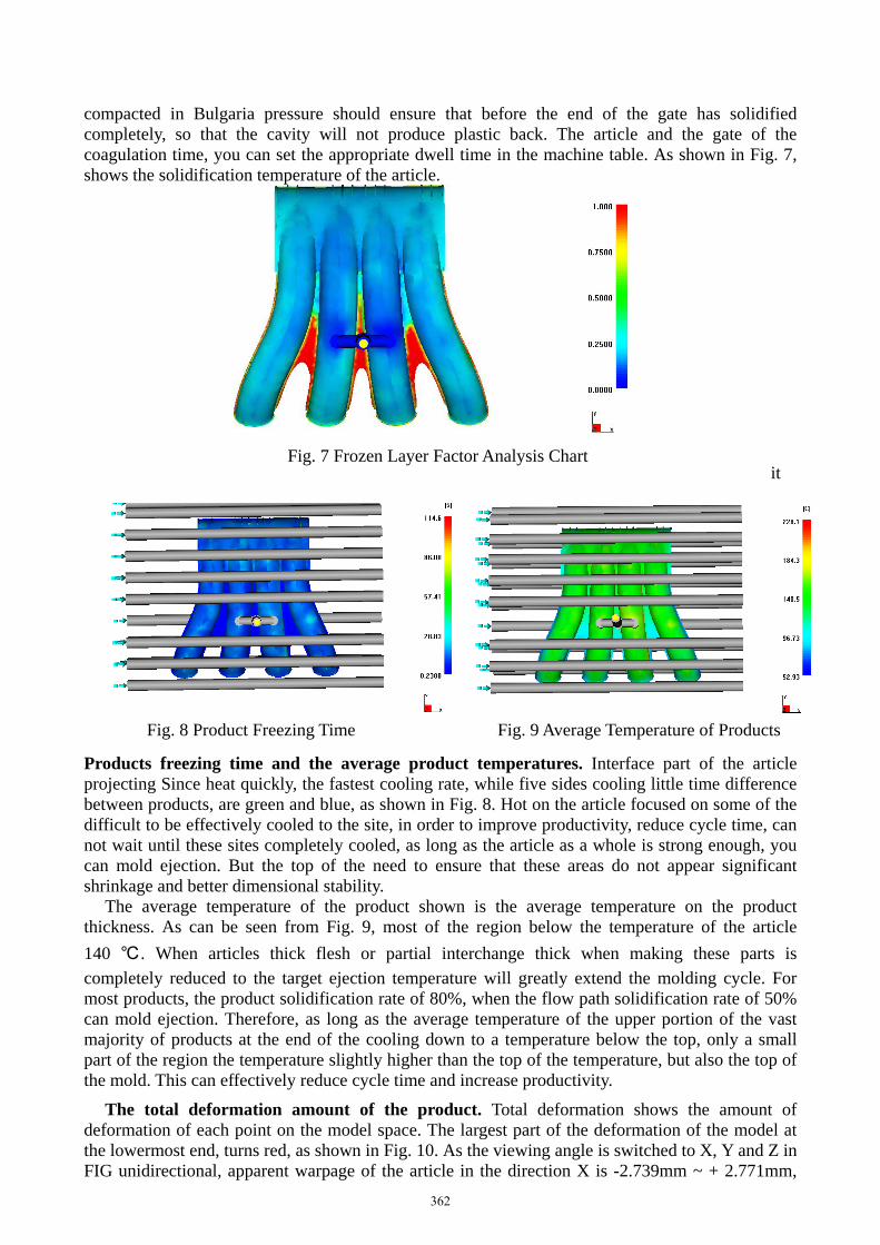
compacted in Bulgaria pressure should ensure that before the end of the gate has solidified completely, so that the cavity will not produce plastic back. The article and the gate of the coagulation time, you can set the appropriate dwell time in the machine table. As shown in Fig. 7, shows the solidification temperature of the article.
it
Products freezing time and the average product temperatures. Interface part of the article projecting Since heat quickly, the fastest cooling rate, while five sides cooling little time difference between products, are green and blue, as shown in Fig. 8. Hot on the article focused on some of the difficult to be effectively cooled to the site, in order to improve productivity, reduce cycle time, can not wait until these sites completely cooled, as long as the article as a whole is strong enough, you can mold ejection. But the top of the need to ensure that these areas do not appear significant shrinkage and better dimensional stability.
The average temperature of the product shown is the average temperature on the product thickness. As can be seen from Fig. 9, most of the region below the temperature of the article 140 ℃ . When articles thick flesh or partial interchange thick when making these parts is completely reduced to the target ejection temperature will greatly extend the molding cycle. For most products, the product solidification rate of 80%, when the flow path solidification rate of 50% can mold ejection. Therefore, as long as the average temperature of the upper portion of the vast majority of products at the end of the cooling down to a temperature below the top, only a small part of the region the temperature slightly higher than the top of the temperature, but also the top of the mold. This can effectively reduce cycle time and increase productivity.
The total deformation amount of the product. Total deformation shows the amount of deformation of each point on the model space. The largest part of the deformation of the model at the lowermost end, turns red, as shown in Fig. 10. As the viewing angle is switched to X, Y and Z in FIG unidirectional, apparent warpage of the article in the direction X is -2.739mm ~ + 2.771mm,
Fig. 7 Frozen Layer Factor Analysis Chart
Fig. 8 Product Freezing Time Fig. 9 Average Temperature of Products
362

the amount of warpage Y is -3.256mm ~ + 2.631mm, Z direction the amount of warpage -2.570mm ~ + 5.936mm, are within the allowable tolerance range.
Conclusion In this paper, automotive engine intake manifold as specific examples of injection molding
process analysis and die design, after the completion of the process analysis and calculation, application Moldflow analysis software gate location, the product temperature distribution, volume contraction, solidification sequence and time were analysis and design. The following conclusions are gained:
(1) Mature injection mold CAE analysis software used in injection molding processes in automotive products, which can effectively guide the design and manufacture of plastic injection mold, improve yields and product development efficiency.
(2) Research on how to Pro / E models into Moldflow software data format to achieve an effective conversion of CAD / CAE, and summed up several effective grid approach. These methods are equally applicable to other modules Moldflow.
(3) For the engine intake manifold injection-molding process analysis and design, filling liquidity forecast insufficient and warpage problems that may occur, which is further improved injection molding process and die structure of the kinds of products providing technical solutions.
(4) Through these analysis, such as the intake manifold of pouring water into a two-point mode, switching, volume shrinkage, warpage amount of clotting time and speed of its products average temperature / pressure are within reasonable limits, Description this injection molding process is feasible to produce qualified injection-molded articles. But it must be noted that, for a large area of thin wall plastic parts, when the cooling circuit is arranged, should be a focus of plastic parts in the middle of cooling, in order to avoid a larger injection products after leaving the warpage tolerance products dimensional accuracy.
These results indicate that by using Moldflow software analysis for automotive engine intake manifold plastic injection molding process, it is possible to predict the injection molded articles of various defects and deficiencies that may arise during, which the design and manufacture of similar products, has an important guiding significance.
References
[1] Shojaei A, Ghaffarian S R, Karimian S M H. Simulation of the three-dimensional non isothermal mold filling process in resin transfer molding. Composites science and technology, 2003, 63: 1931-1948.
[2] Liu Shib Jung. Effects of Processing Parameters on Formation of Sink Marks on Injection
Fig. 10 Deformation Distribution of the Product
363

Molded Parts. Plastics, Rubber and Composites, 2002.22:229-248.
[3] Yu Weidong. Injection molding CAE technology. Computer-aided design and manufacturing, 2002,3: 60-62 (In Chinese).
[4] Shepel Sergey V., Samuel Paolucci. Numerical simulation of filling and solidification of permanent model casting. Applied Thermal Engineering, 2002.22:229-248.
[5] WANG Shu-xun. Sheet based on Moldflow injection molding filling process. Manufacturing Automation Research, 2010,6 (32): 50-54 (In Chinese).
[6] Wang Gang. A single rock analysis based Moldflow. Mold Beijing: Tsinghua University Press, 2004 (In Chinese).
[7] Kun Li. Die Optimization Design of Center Cover Kinds of Injection Mold Based on Moldflow. Light Industry Machinery, 2012(4): 18-21 (In Chinese).
[8] Zheng Zijun, Fu Xialong. Moldflow-based optimization of feeding system for cup shell of soy.
Milk Preparation Machine, 2013(2): 15-18 (In Chinese).
364


![INTEGRATED NUMERICAL SIMULATION OF INJECTION MOLDING … · injection molding filling simulation [8]. Numerical experiments confirm the reliability and efficiency of the solver. Integrated](https://static.fdocuments.in/doc/165x107/5d0d0f7388c993ed388b4830/integrated-numerical-simulation-of-injection-molding-injection-molding-filling.jpg)
