Computer Organization - Vidya Jyothi Institute of...
83
Computer Organization It describes the function and design of the various units of digital computers that store and process information. It also deals with the units of computer that receive information from external sources and send computed results to external destinations
Transcript of Computer Organization - Vidya Jyothi Institute of...
Computer Organization
It describes the function and design of the various units of
digital computers that store and process information.
It also deals with the units of computer that receive
information from external sources and send computed
results to external destinations
“Computer Organization” & “Computer Architecture”
“Computer Organization” and “Computer Architecture” are the terms used in describing digital computer systems.
Computer architecture deals with the instruction sets, address fields, operation codes, addressing modes, effective utilization of I/O mechanisms and such other aspects which would interest the users of computers.
Computer organization include hardware details such as generation of control signals, interface between the computer and peripherals, memory technologies used, modular design, flow of data, control mechanisms and so on.
In brief, a programmer is generally more concerned about the architectural features and a designer of computer systems is more concerned about the organizational aspects.

Computer types
Digital computer :
It is a fast electronic calculating machine that accepts digitized input information, processes it according to a list of internally stored instructions, and produces the resulting output information.
(1) Personal computer :
It is the most common form of desktop computers.
Desk top computers have processing and storage units, visual display and audio output units, and a keyboard that can all be located easily on a home or office desk. The storage media include hard disks, CD-ROMs and diskettes.
Portable notebook computers are a compact version of the personal computers with all of these components packaged into single unit the size of a thin briefcase
Computer types (contd.,)
(2) Workstations:
Work stations with high resolution graphics input/output capability,
although still retaining the dimensions of desktop computers, have
significantly more computational power than personal computers.
Workstations are often used in engineering applications, especially
for interactive design works.
(3) Enterprise systems or mainframes:
These are used for business data processing in medium to large
corporations that require much more computing power and storage
capacity than workstations can provide.
Computer types (contd.,)
4) Servers :
Servers contain sizable database storage units and are capable of
handling large volumes of requests to access the data.
The Internet and its associated servers have become a dominant world
wide source of all types of information.
5) Super Computers :
Super Computers are used for the large scale numerical calculations
required in applications such as weather forecasting, aircraft design
and simulation.
Functional units
A computer consists of five functionally independent main parts:
Input unit
Memory unit
Arithmetic and logic unit (ALU)
Output unit
Control unit
The structure of a digital computer is shown below
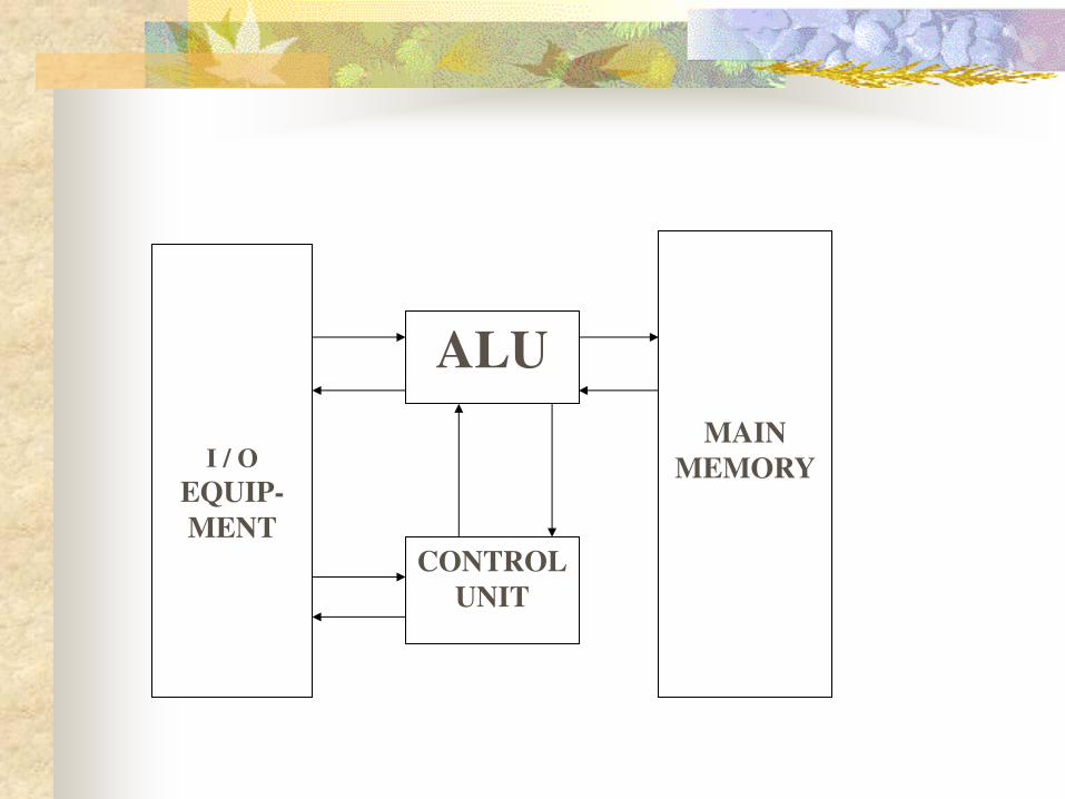
I / O
EQUIP-
MENT
MAIN
MEMORY
ALU
CONTROL
UNIT
Operation of a computer
The computer accepts information in the form of programs and data
through an input unit and stores it in the memory.
Information stored in the memory is fetched, under program control,
into an arithmetic and logic unit, where it is processed.
Processed information leaves through an output.
All activities inside the machine are directed by the control unit.
Input unit
Computers accept coded information through input units.
The most well known input device is key board.
Whenever a key is pressed, the corresponding letter or digit is
automatically translated into its corresponding binary code and
transmitted over a cable to either the memory or the processor.
Memory unit
The function of the memory is to store programs and data.
There are two classes of storage, called primary and secondary.
Primary storage is a fast memory that operates at electronic speeds.
Programs must stay in memory while they are being executed.
The memory contains a large number of semiconductor storage cells,
each capable of storing one bit of information.
Random access memory: Memory in which any location can be
reached in a short and fixed amount of time after specifying its
address is called random access memory (RAM).
Memory unit (Contd.,)
The time required to access one word is called the memory access
time.
Cache memory: The small, fast, Ram units are called caches.
They are tightly coupled with the processor and are often contained
on the same integrated circuit chip to achieve high performance.
Main memory: The largest and slowest unit is referred to as the main
memory.
Memory unit (Contd.,)
Secondary storage:
Although primary storage is essential, it tends to be expensive.
Thus additional, cheaper, secondary storage is used when large
amounts of data and many programs have to be stored, particularly
for information that is accessed infrequently.
A wide selection of secondary storage devices is available, including
magnetic disks,tapes and optical disks (CD-ROMs)
Arithmetic and logic unit (ALU)
Most computer operations are executed in in the arithmetic and logic unit (ALU) of the processor.
For example, Suppose two numbers are to be added.
They are brought into the processor, and the actual addition is carried out by the ALU.
The sum may then be stored in the memory or retained in the processor for immediate use.
When operands are brought into the processor, they are stored in high-speed storage elements called registers.
Output unit
The output unit is the counterpart of input unit.
Its function is to send processed results to the outside world.
The most familiar example of such a device is a printer.
Some units, such as graphic displays, provide an input function and
an output function. The dual role of such units is the reason for using
the single name I/O unit in many cases.
Control unit
The memory, arithmetic and logic, and I/O units store and process
information and perform input and output operations.
The operations of these units are coordinated by control unit.
The control unit is effectively the nerve center that sends control
signals to other units and senses their states.
Basic operational concepts
To perform a given task, an appropriate program consisting of a list of
instructions is stored in the memory.
Individual instructions are brought from the memory into the
processor, which execute the specified operations.
Data to be used as operands are also stored in the memory

Basic operational concepts (Contd.,)
Consider, the two instruction sequence
Load LOCA, R1
Add R1, R0
The first of these instructions transfers the contents of memory
location LOCA into processor register R1, and second instruction
adds the contents of register R1 as well as those of R0 and places the
sum into R0.
Note that this destroys the former contents of R1 as well as R0, where
as the original contents of memory location LOCA are preserved.
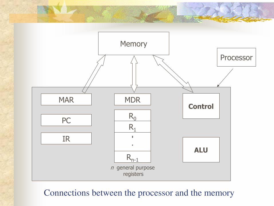
Connections between the processor and the memory
MAR
PC
IR
MDR
R0
R1 . . .
Rn-1
Control
ALU
n general purpose registers
Memory
Processor
Instruction register (IR)
The instruction register holds the instruction that is currently being
executed.
Its output is available to the control circuits, which generate the
timing signals that control the various processing elements involved
in executing the instruction
Program counter (PC)
The program counter is another specialized register.
It keeps track of the execution of a program.
It contains the memory address of the next instruction to be fetched
and executed.
During the execution of an instruction, the contents of of the PC are
updated to correspond to the address of the next instruction to be
executed.
It is customary to say that PC points to the next instruction that is to
be fetched from the memory.
Memory address register (MAR) & Memory data register (MDR)
These two registers facilitate communication with the memory.
The MAR holds the address of the location to be accessed.
The MDR contains the data to be written into or read out of the
addressed location.
Operating steps for Program execution
Programs are stored in the memory through the input unit.
Execution of the program starts when the PC is set to point to the first
instruction of the program.
The contents of the PC are transferred to the MAR and a Read control
signal is sent to the memory.
After the time required to access the memory elapses, the addressed
word (in this case, the first instruction of the program) is read out of
the memory and loaded into the MDR.
Operating steps for Program execution (Contd.,)
Next, the contents of the MDR are transferred to the IR .
At this point, the instruction is ready to be decoded and executed.
If the instruction involves an operation to be performed by the ALU,
it is necessary to obtain the required operands.
If an operand resides in memory ( it could also be in a general-
purpose register in the processor), it has to be fetched by sending its
address to the MAR and initiating a Read cycle.
Operating steps for Program execution (Contd.,)
When the operand has been read from the memory into the MDR, it is
is transferred from the MDR to the ALU.
After one or more operands are fetched in this way, the ALU can
perform the desired operation.
If the result of the operation is to be stored in the memory, then the
result is sent to the MDR.
The address of the location where the result is to be stored is sent to
the MAR, and a write cycle is initiated.

Operating steps for Program execution (Contd.,)
At some point during the execution of the current instruction, the
contents of the PC are incremented so that the PC points to the next
instruction to be executed.
Thus, as soon as the execution of the current instruction is completed,
a new instruction fetch may be started.
In addition to transferring data between the memory and the
processor, the computer accepts data from input devices and sends
data to output devices. Thus, some machine instructions with the
ability to handle I/O transfers are provided.
Interrupt service routine
Normal execution of a programs may be preempted if some device requires urgent servicing.
For example, a monitoring device in a computer-controlled industrial process may detect a dangerous condition.
In order to deal with the situation immediately, the normal execution of the current program must be interrupted.
To do this, the device raises an interrupt signal.
An interrupt is a request from an I/O device for service by the processor.
The processor provides the requested service by executing an appropriate interrupt-service routine.
Interrupt service routine (contd.,)
Because such diversions may alter the internal state of the processor,
its state must be saved in the memory locations before servicing the
interrupt.
Normally, the contents of the PC, the general registers, and some
control information are stored in memory.
When the interrupt service routine is completed, the state of the
processor is restored so that the interrupted program may continue.
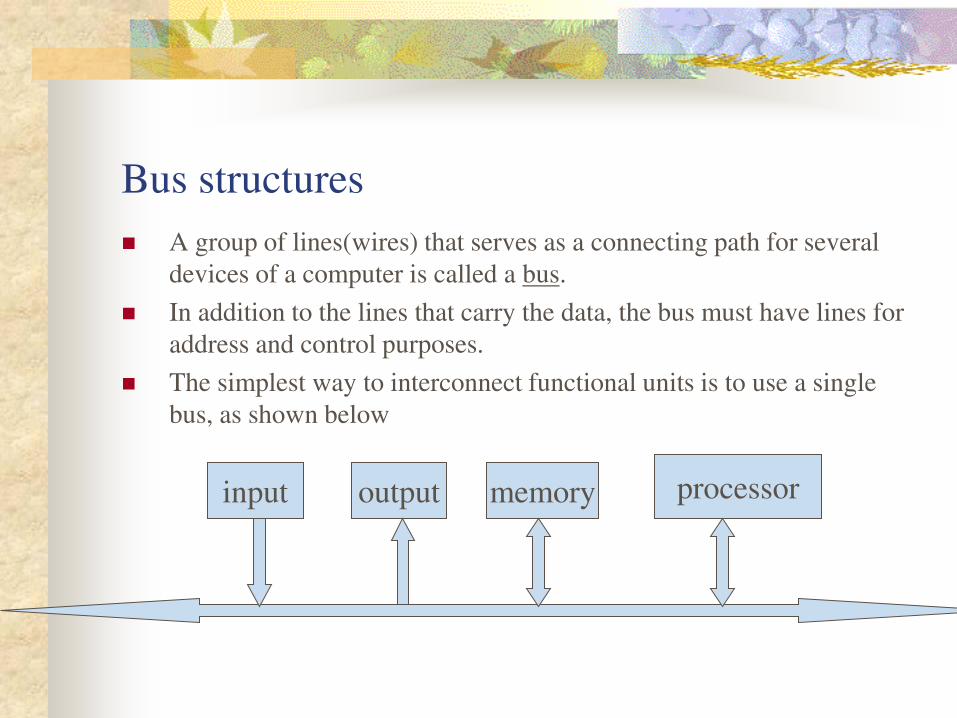
Bus structures
A group of lines(wires) that serves as a connecting path for several
devices of a computer is called a bus.
In addition to the lines that carry the data, the bus must have lines for
address and control purposes.
The simplest way to interconnect functional units is to use a single
bus, as shown below
input output memory processor
Bus structures (contd.,)
All units are connected to this bus. Because the bus can be used for
only one transfer at a time, only two units can actively use the bus at
any given time.
Bus control lines are used to arbitrate multiple requests for use of the
bus.
The main virtue of the single-bus structure is its low cost and its
flexibility for attaching peripheral devices.
Systems that contain multiple buses achieve more concurrency in
operations by allowing two or more transfers to be carried out at the
same time.This leads to better performance but at an increased cost.
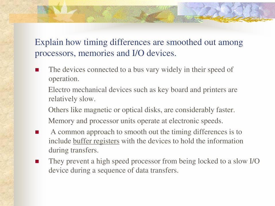
Explain how timing differences are smoothed out among
processors, memories and I/O devices.
The devices connected to a bus vary widely in their speed of
operation.
Electro mechanical devices such as key board and printers are
relatively slow.
Others like magnetic or optical disks, are considerably faster.
Memory and processor units operate at electronic speeds.
A common approach to smooth out the timing differences is to
include buffer registers with the devices to hold the information
during transfers.
They prevent a high speed processor from being locked to a slow I/O
device during a sequence of data transfers.
Contd.,
This allows the processor to switch rapidly from one device to
another, interweaving its process activity with data transfers involving
several I/O devices.
Thus, buffer registers smooth out timing differences among
processors, memories and I/O devices.
Software Explain the role of system software in a computer.
System software is responsible for the coordination of all activities in a computing system.
System software is a collection of programs that are executed as needed to perform functions such as
1) Receiving and interpreting user commands.
2) Entering and editing application programs and storing them as files in secondary storage devices.
3) Managing the storage and retrieval of files in secondary storage devices.
Contd.,
4) Running standard application programs such as word processors,
spread sheets, or games, with data supplied by the user.
5) Controlling I/O units to receive input information and produce output
results.
6) Translating programs from high level language to low level language.
7) Linking and running user-written application programs with existing
standard library routines, such as numerical computation packages.
Explain various components of system software.
Compiler : A system software program which translates the high-
level language program into a suitable machine language program.
Text editor: Another important system program that all
programmers use is a text editor.
It is used for entering and editing application programs.
The user of this program interactively execute commands that allow
statements of a source program entered at a keyboard to be
accumulated in a file.
Contd.,
Operating system (OS)
It is a key system software component.
This is a large program, or actually a collection of routines , that is
used to control the sharing of and interaction among various computer
units as they execute application programs.
The OS routines perform the tasks required to assign computer
resources to individual application programs.
These tasks include assigning memory to program and data files,
moving data between memory and disk units, and handling I/O
operations.

Performance
Discuss various parameters for improving the performance of a
computer.
The most important measure of the performance of a computer is how
quickly it can execute a programs.
The speed with which a computer executes programs is affected by
the design of its hardware and its machine language instructions.
Elapsed time: The total time required to execute a program .
This elapsed time is a measure of the performance of the entire
computer system.
It is affected by the speed of the processor, the disk and the printer.
Contd.,
Processor time:
Here we have to consider only those periods of the elapsed time, during which the processor is active.
The sum of these periods is called processor time.
The processor time depends on the hardware involved in the execution of individual machine instructions.
Cache memory:
The processor and a relatively small cache memory can be fabricated on a single IC chip.
The internal speed of performing the basic steps of instruction processing on such chips is very high and considerably faster than the speed at which instructions and data can be fetched from the main memory.

Contd.,
A program will be executed faster if the movement of instructions and
data between the main memory and processor is minimized, which is
achieved by using the cache.
Main
memory Processor Cache
memory
Bus
Processor clock
Processor circuits are controlled by a timing signal called a clock .
The clock defines regular time intervals, called clock cycles.
To execute a machine instruction, the processor divides the action to
be performed into a sequence of basic steps, such that each step can
be completed in one clock cycle.
The length P of one clock cycle is an important parameter that affects
processor performance.
Its inverse is the clock rate, R = 1/P , which is measured in cycles per
second .
If the clock rate is 500 million cycles per second, then the
corresponding clock period is 2 nanoseconds.
Basic performance equation
Let ‘T’ be the processor time required to execute a program that has been prepared in some high level language.
Assume that the complete execution of the program requires the
execution of ‘N’ machine language instructions. Suppose that the average number of basic steps needed to execute one
machine instruction is ‘S’. If the clock rate is ‘R’ cycles per second, the program execution time
is given by
T = N . S
R
This is often referred to as the basic performance equation.
Pipelining and Super scalar operation
A substantial improvement in performance can be achieved by
overlapping the execution of successive instructions, using a
technique called pipelining .
Consider the instruction
Add R1, R2, R3
Which adds the contents of registers R1 and R2, and places the sum
into R3.
The contents of R1 and R2 are first transferred to the inputs of the
ALU.
After the add operation is performed, the sum is transferred to R3.
Processor can read the next instruction from the memory while the
addition operation is being performed.
Pipelining (contd.,)
Then, if that instruction also uses the ALU, its operands can be
transferred to the ALU inputs at the same time that the result of Add
instruction is being transferred to R3.
Thus, pipelining increases the rate of executing instructions
significantly and cause the effective value of S to approach 1.
Super scalar operation
A higher degree of concurrency can be achieved if multiple
instruction pipelines are implemented in the processor.
This means that multiple function units are used, creating parallel
paths through which different instructions can be executed in parallel.
With such an arrangement, it becomes possible to start the execution
of several instructions in every clock cycle.
This mode of execution is called Super scalar operation
Clock rate
There are two possibilities for increasing the clock rate, R.
First, improving the IC technology makes logic circuit faster, which
reduces the the needed to complete a basic step. This allows the clock
period, P, to be reduced and the clock rate, R, to be increased.
Second, reducing the amount of processing done in one basic step
also makes it possible to reduce the clock period , P.
Instruction set : CISC and RISC
The terms CISC and RISC refer to design principles and techniques.
RISC : Reduced instruction set computers
Simple instructions require a small number of basic steps to execute.
For a processor that has only simple instructions, a large number of
instructions may be needed to perform a given programming task.
This could lead to a large value of N and a small value for S.
It is much easier to implement efficient pipelining in processors with
simple instruction sets.
Instruction set : CISC and RISC (contd.,)
CISC: Complex instruction set computers.
Complex instructions involve a large number of steps.
If individual instructions perform more complex operations, fewer
instructions will be needed, leading to a lower value of N and a larger
value of S.
Complex instructions combined with pipelining would achieve good
performance.
Compiler
A compiler translates a high-level language program into a sequence
of machine instructions
To reduce N, we need to have a suitable machine instruction set and a
compiler that makes good use of it.
An optimizing compiler takes advantage of various features of the
target processor to reduce the product N.S .
The compiler may rearrange program instructions to achieve better
performance.
Performance measurement
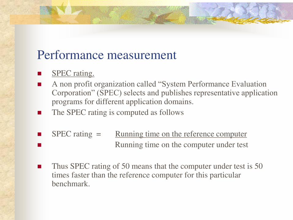
SPEC rating.
A non profit organization called “System Performance Evaluation Corporation” (SPEC) selects and publishes representative application programs for different application domains.
The SPEC rating is computed as follows
SPEC rating = Running time on the reference computer
Running time on the computer under test
Thus SPEC rating of 50 means that the computer under test is 50 times faster than the reference computer for this particular benchmark.
Contd.,
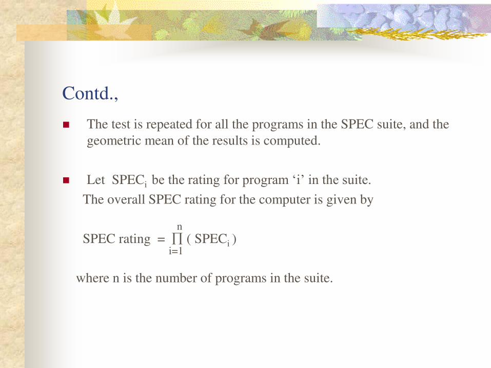
The test is repeated for all the programs in the SPEC suite, and the
geometric mean of the results is computed.
Let SPECi be the rating for program ‘i’ in the suite. The overall SPEC rating for the computer is given by
SPEC rating = ( SPECi )
where n is the number of programs in the suite.
i=1
n
Multiprocessors
Large computer systems may contain a number of processor units, in
which case they are called multiprocessor systems.
These systems either execute a number of different application tasks
in parallel, or they execute subtasks of a single large task in parallel.
All processors usually have access to all of the memory in such
systems, and the term shared-memory multiprocessor systems is often
used to make this clear.
Multiprocessors (contd.,)
The high performance of these systems comes with much increased
complexity and cost.
In addition to multiple processors and memory units, cost is increased
because of the need for more complex interconnection networks.
Multi-computers
In contrast to multiprocessor systems, it is possible to use an
interconnected group of complete computers to achieve high total
computational power.
The computers normally have access only to their own memory units.
When the tasks they are executing need to communicate data, they do
so by exchanging messages over a communication network.
This property distinguishes them from shared-memory
multiprocessors, leading to the name message-passing multi-
computers.
Data Representation
Data types :
The data types found in the registers of digital computers are classified
into three categories.
1) Numbers used in arithmetic computations.
2) Letters used in data processing.
3) Other symbols used for specific purpose.
All types of data, except binary numbers, are represented in computer
registers in binary-coded form.
Number systems
A number system of base (or radix) r, uses r distinct symbols for its digits.
Base 10 uses 10 symbols (Decimal system).
0 1 2 3 4 5 6 7 8 9
The number 892.5 is
8 (10)2 + 9(10)1 + 2 (10)0 + 5 (10)-1
Common base values
Binary : 0 , 1
Octal : 0 , 1 , 2 , 3 4 , 5 , 6 , 7
Hexadecimal : 0 , 1 , 2 , 3 , 4 , 5 , 6 , 7 , 8 , 9 , A , B , C , D , E , F
A,B,C,D,E,F correspond to the decimal numbers 10,11,12,13,14,15 respectively.
Convert to decimal
(101101)2 = 1(25) + 0(24) + 1(23) + 1(22) + 0(21) + 1(20) = (45)10
(672.4)8
= 6(82)+7 (81)+ 2 (80) + 7(80) + 4.(8-1)
= 6(64) + 7(8) + 2(1) + 4 (1/8) = (442.5)10
(FADE)16 = 15.(16)3+10.(16)2+13.(16)1+14.(16)0
= 15.(4096)+10.(256)+13.(16) + 14 = (64222)10
(DEAF)16= (57007)10
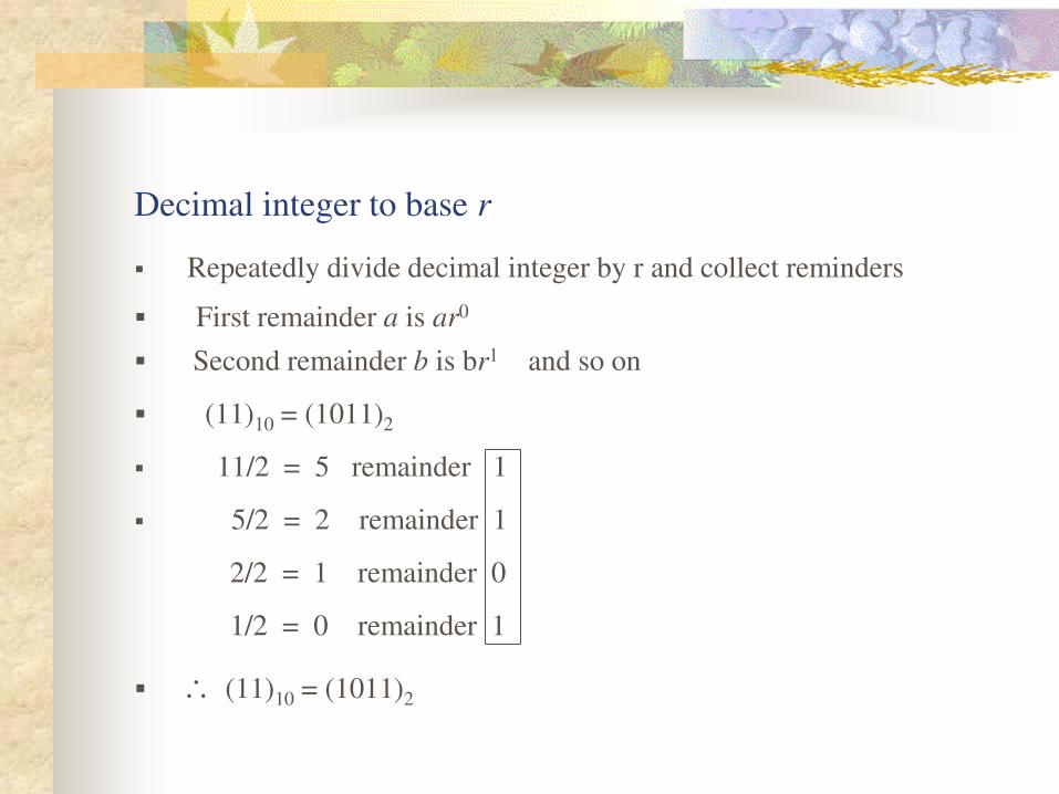
Decimal integer to base r
Repeatedly divide decimal integer by r and collect reminders
First remainder a is ar0
Second remainder b is br1 and so on
(11)10 = (1011)2
11/2 = 5 remainder 1
5/2 = 2 remainder 1
2/2 = 1 remainder 0
1/2 = 0 remainder 1
(11)10 = (1011)2
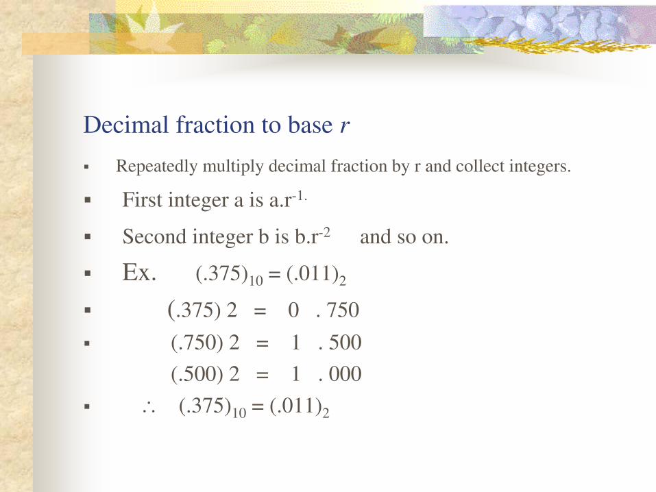
Decimal fraction to base r
Repeatedly multiply decimal fraction by r and collect integers.
First integer a is a.r-1.
Second integer b is b.r-2 and so on.
Ex. (.375)10 = (.011)2
(.375) 2 = 0 . 750
(.750) 2 = 1 . 500
(.500) 2 = 1 . 000
(.375)10 = (.011)2
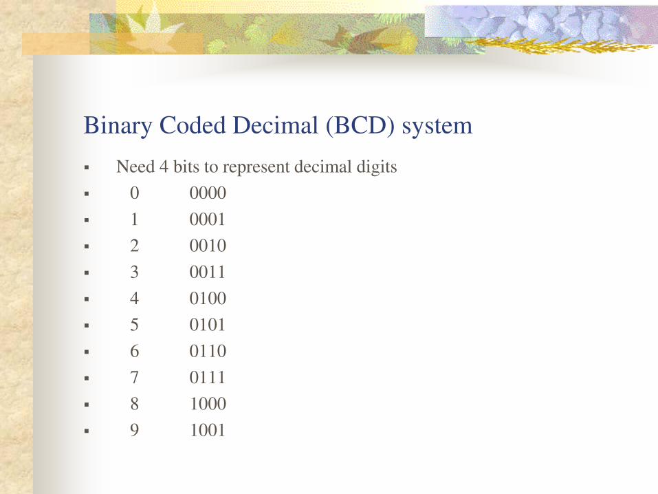
Binary Coded Decimal (BCD) system
Need 4 bits to represent decimal digits
0 0000
1 0001
2 0010
3 0011
4 0100
5 0101
6 0110
7 0111
8 1000
9 1001
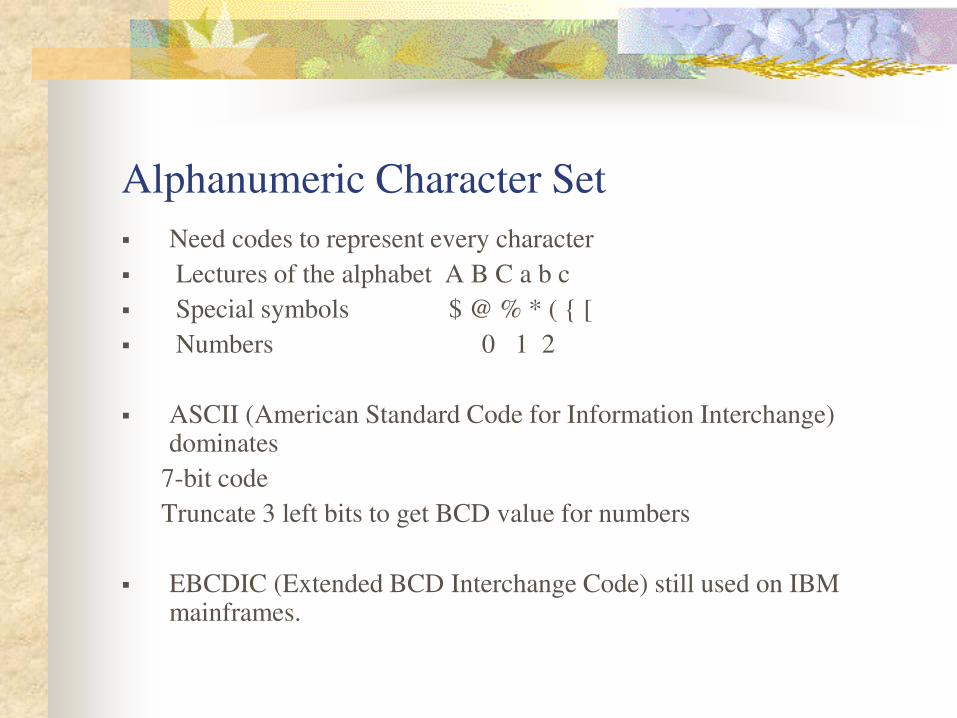
Alphanumeric Character Set
Need codes to represent every character
Lectures of the alphabet A B C a b c
Special symbols $ @ % * ( { [
Numbers 0 1 2
ASCII (American Standard Code for Information Interchange) dominates
7-bit code
Truncate 3 left bits to get BCD value for numbers
EBCDIC (Extended BCD Interchange Code) still used on IBM mainframes.
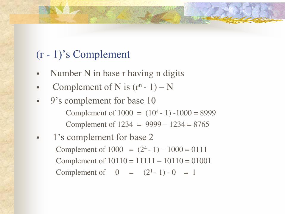
(r - 1)’s Complement
Number N in base r having n digits
Complement of N is (rn - 1) – N
9’s complement for base 10
Complement of 1000 = (104 - 1) -1000 = 8999
Complement of 1234 = 9999 – 1234 = 8765
1’s complement for base 2
Complement of 1000 = (24 - 1) – 1000 = 0111
Complement of 10110 = 11111 – 10110 = 01001
Complement of 0 = (21 - 1) - 0 = 1
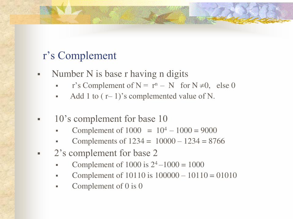
r’s Complement Number N is base r having n digits
r’s Complement of N = rn – N for N 0, else 0
Add 1 to ( r– 1)’s complemented value of N.
10’s complement for base 10 Complement of 1000 = 104 – 1000 = 9000
Complements of 1234 = 10000 – 1234 = 8766
2’s complement for base 2 Complement of 1000 is 24 –1000 = 1000
Complement of 10110 is 100000 – 10110 = 01010
Complement of 0 is 0
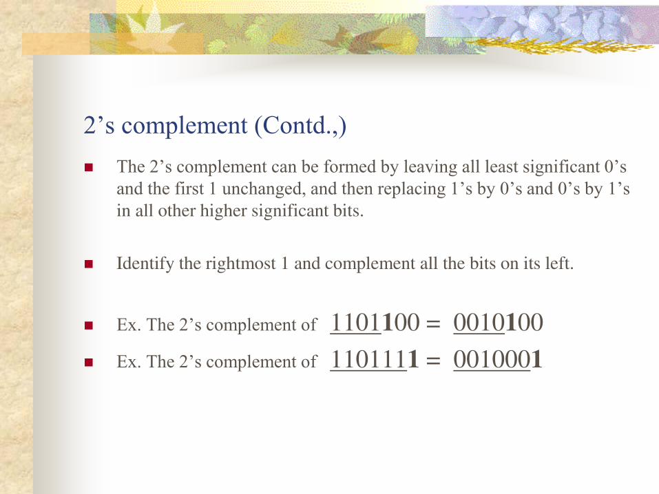
2’s complement (Contd.,) The 2’s complement can be formed by leaving all least significant 0’s
and the first 1 unchanged, and then replacing 1’s by 0’s and 0’s by 1’s in all other higher significant bits.
Identify the rightmost 1 and complement all the bits on its left.
Ex. The 2’s complement of 1101100 = 0010100
Ex. The 2’s complement of 1101111 = 0010001
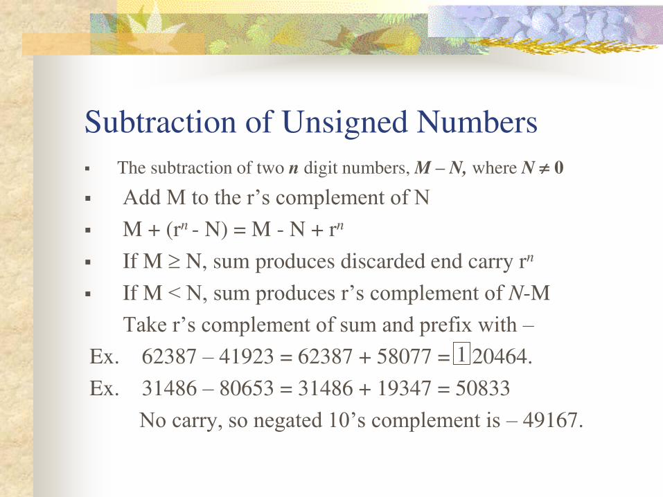
Subtraction of Unsigned Numbers
The subtraction of two n digit numbers, M – N, where N 0
Add M to the r’s complement of N
M + (rn - N) = M - N + rn
If M N, sum produces discarded end carry rn
If M< N, sum produces r’s complement of N-M
Take r’s complement of sum and prefix with –
Ex. 62387 – 41923 = 62387 + 58077 = 20464.
Ex. 31486 – 80653 = 31486 + 19347 = 50833
No carry, so negated 10’s complement is – 49167.
1
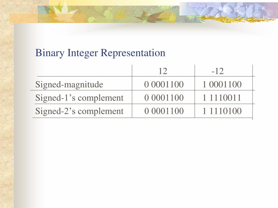
Binary Integer Representation
12 -12
Signed-magnitude 0 0001100 1 0001100
Signed-1’s complement 0 0001100 1 1110011
Signed-2’s complement 0 0001100 1 1110100
Computer Arithmetic
Signed-magnitude awkward.
Signed-1’s complement has two representations for zero: -0 and +0.
Therefore, signed -2’s complement is used.

Arithmetic Addition
Simply add the two numbers and discard any leftmost
carry out bit.
Negative numbers are in 2’s complement Including the result!
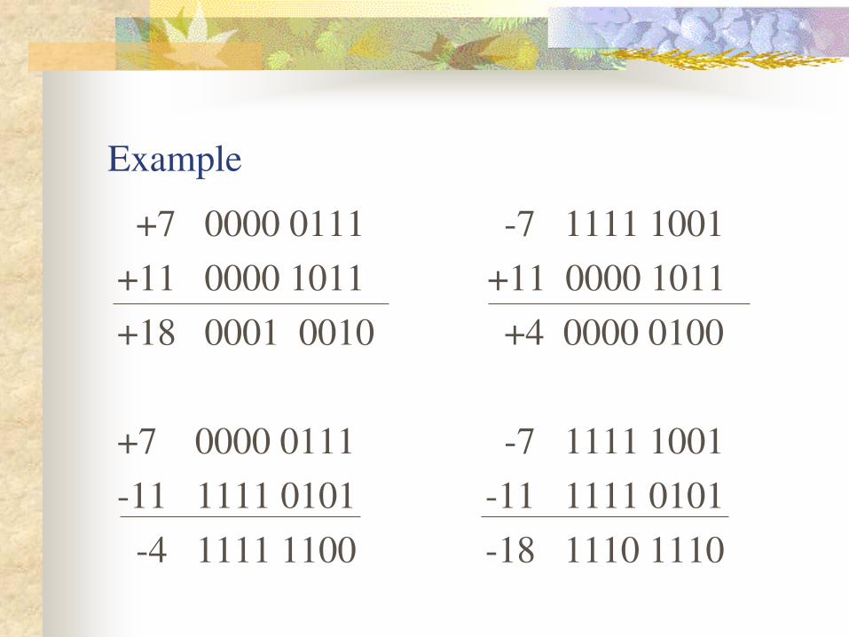
Example
+7 0000 0111 -7 1111 1001
+11 0000 1011 +11 0000 1011
+18 0001 0010 +4 0000 0100
+7 0000 0111 -7 1111 1001
-11 1111 0101 -11 1111 0101
-4 1111 1100 -18 1110 1110
Arithmetic Subtraction
Minuend – subtrahend = result
Minuend + subtrahend’s r’s complement = result Simply add the two numbers and discard any leftmost
carry out bit
Negative numbers are in 2’s complement Including the result!
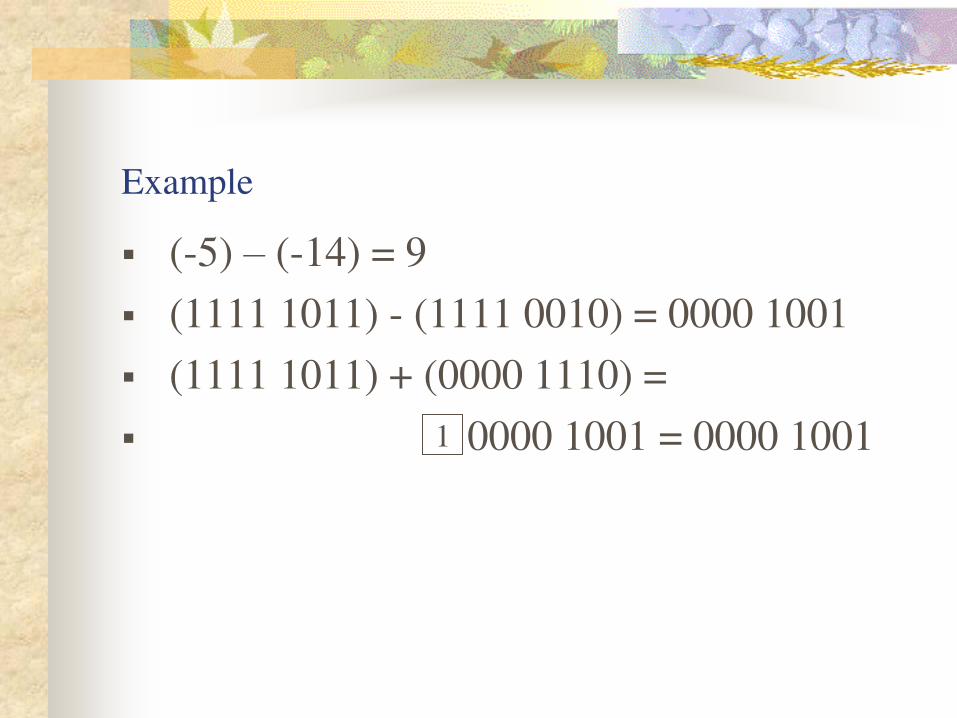
Example
(-5) – (-14) = 9
(1111 1011) - (1111 0010) = 0000 1001
(1111 1011) + (0000 1110) =
0000 1001 = 0000 1001
1
Overflow
When two numbers of n digits are added and the sum occupies
‘n+1’ digits, we say that an overflow occurred.
An overflow is a problem in digital computers because the
width of the registers is finite.
A result that contains ‘n+1’ bits cannot be accommodated in a register with a standard length of n bits.
Overflow Detection
An overflow condition can be detected by observing the carry into the
sign bit position and the carry out of the sign bit position.
If these two carries are not equal, an overflow condition is produced.
If the two carries are applied to an exclusive –OR gate, an overflow
will be detected when the output of the gate is equal to1.
carry in = carry out in high-order digit
No overflow
Carry in carry out in high-order digit
Overflow
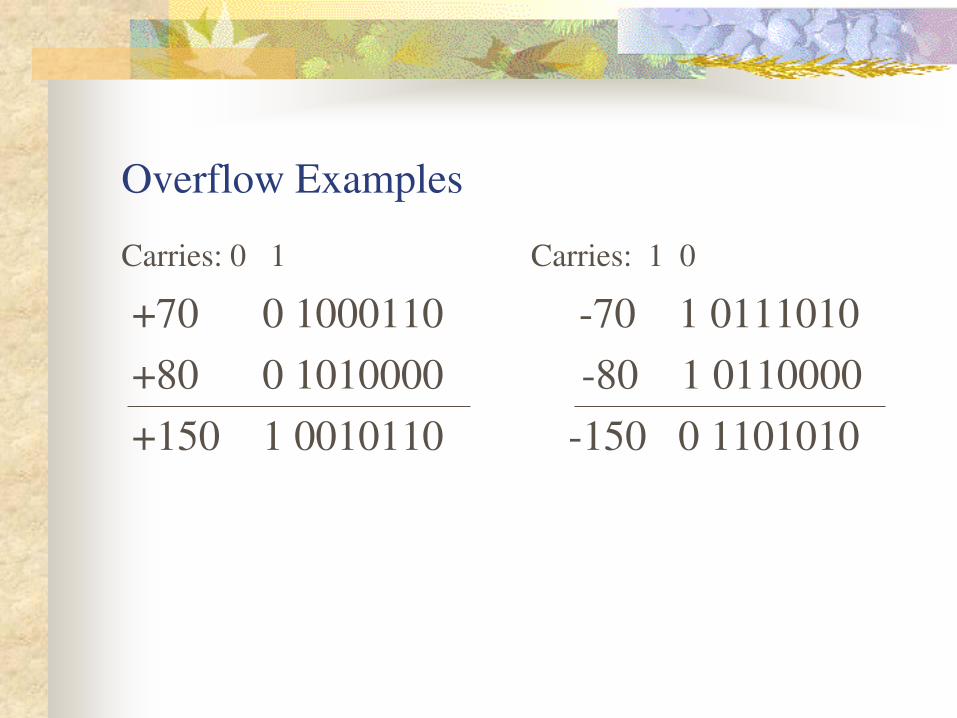
Overflow Examples
Carries: 0 1 Carries: 1 0
+70 0 1000110 -70 1 0111010
+80 0 1010000 -80 1 0110000
+150 1 0010110 -150 0 1101010
Floating Point Representation
A floating point is always interpreted to represent a
number in the following form:
m.re
r is base (radix)
e is exponent
Only the mantissa ‘m’ and the exponent ‘e’ are physically represented in the register(including their sign)
A floating-point binary number is said to be normalized if
the most significant digit of the mantissa ‘m’ is nonzero.
Floating Point Representation (Contd.,)
Normalized numbers provide the maximum possible precision for the
floating-point number.
A zero cannot be normalized because it does not have a nonzero digit.
It is usually represented in the floating point by all 0’s in the mantissa and exponent.
Decimal number +6132.789 is represented in floating point with a
fraction and an exponent as follows:
Mantissa: +.6132789 Exponent:+04
Floating Point Representation (Contd.,)
Binary number +1001.11 is represented with an 8-bit fraction and a
six bit exponent as follows:
Mantissa: 01001110 Exponent: 0000100
The fraction has a zero in the leftmost position to denote positive.
The binary point of the fraction follows the sign bit but is not shown
in the register.
The floating point number is equivalent to
m 2e = + (.10001110)2 2+4.
Floating Point Representation (Contd.,)
Arithmetic operations with floating-point numbers are more
complicated than arithmetic with fixed point numbers and their
execution takes longer and requires more complex hardware.
However, floating point representation is a must for scientific
computations because of the scaling problems involved with
fixed-point computations.
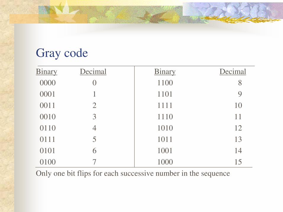
Gray code
Binary Decimal Binary Decimal
0000 0 1100 8
0001 1 1101 9
0011 2 1111 10
0010 3 1110 11
0110 4 1010 12
0111 5 1011 13
0101 6 1001 14
0100 7 1000 15
Only one bit flips for each successive number in the sequence
Gray code (contd.,)
The advantage of Gray code over straight binary numbers is that the
Gray code changes by only one bit as it sequences from one number
to the next.
In other words, the change from any number to the next in sequence
is recognized by a change of only one bit from 0to1 or from 1 to 0.
A typical application of the Gray code occurs when the analog data is
represented by the continuous change of a shaft position.
The shaft is partitioned in to segments with each segment is assigned
a number.
If adjacent segments are made to correspond to adjacent gray code
numbers, ambiguity is reduced when the shaft position is in the line
that separates any two segments.
Error detection codes
Binary information transmitted through some form of communication
medium is subject to external noise that could change bits from 1 to 0,
and vice versa.
An error detection code is a binary code that detects digital errors
during transmission.
The most common error detection code used is the parity bit.
A parity bit is an extra bit included with a binary message to make
the total number of 1’s either odd or even.
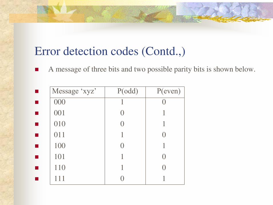
Error detection codes (Contd.,)
A message of three bits and two possible parity bits is shown below.
Message ‘xyz’ P(odd) P(even) 000 1 0
001 0 1
010 0 1
011 1 0
100 0 1
101 1 0
110 1 0
111 0 1
Error detection codes (Contd.,)
The P(odd) bit is chosen in such a way as to make sum of 1’s (all four bits) odd.
The P(even) bit is chosen to make sum of all 1’s even.
In either case the sum is taken over the message and the P bit.
At the sending end, the message is applied to a parity generator,
where the required parity bit is generated.
The message, including the parity bit, is transmitted to its destination.
Error detection codes (Contd.,)
At the receiving end, all the incoming bits are applied to a parity checker that checks the proper parity adopted (odd or even).
An error is detected if the checked parity does not conform to the adopted parity.
The parity method detects the presence of one, three, or any odd number of errors.An even number of errors is not detected.
The even- parity scheme has disadvantage of having a bit combination of all 0’s, while in the odd parity there is always one bit that is 1.
Note that P(odd) is the complement of P(even)


![COMPUTER ORGANIZATION Subject Code: 10CS46 - VTU Solutionvtusolution.in/.../cse-iii-computer__organization_[15cs34]-notes.pdf · COMPUTER ORGANIZATION 10CS46 . COMPUTER ORGANIZATION](https://static.fdocuments.in/doc/165x107/5b7970717f8b9a331e8dcaf3/computer-organization-subject-code-10cs46-vtu-15cs34-notespdf-computer.jpg)